Embed Size (px)
Citation preview

Operator’s Manual
Model 9843
Pulse Oximeter andCarbon Dioxide Detector
0123 English
Caution: Federal law (USA) restricts this device to sale by or on the order of a physician.
Caution: Read this manual carefully before using the Model 9843.
The information in this manual has been carefully checked and is believed to be accurate. In the interest of continued product development, NONIN reserves the right to make changes and improvements to this manual and the products it describes at any time, without notice or obligation.
Nonin Medical, Inc.13700 1st Avenue North
Plymouth, MN 55441-5443 USA
(763) 553-9968 (800) 356-8874 (USA and Canada)
Fax (763) [email protected] www.nonin.com
References to “NONIN” in this manual shall imply Nonin Medical, Inc. Nonin is a registered trademarks of Nonin Medical, Inc.
©2005 Nonin Medical, Inc.
Authorized EC Representative:MPS, Medical Product Service GmbH
Borngasse 20D-35619 Braunfels, Germany
0123
G
1
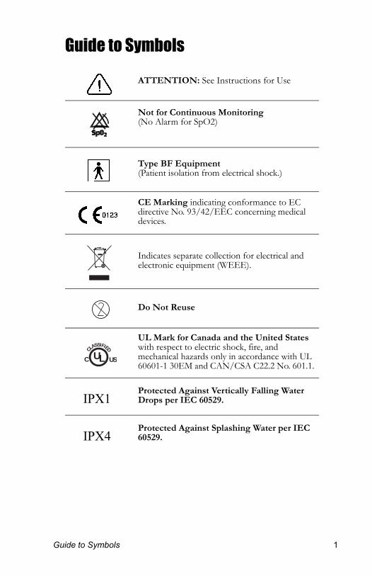
Guide to Symbols
ATTENTION: See Instructions for Use
Not for Continuous Monitoring (No Alarm for SpO2)
Type BF Equipment (Patient isolation from electrical shock.)
CE Marking indicating conformance to EC directive No. 93/42/EEC concerning medical devices.
Indicates separate collection for electrical and electronic equipment (WEEE).
Do Not Reuse
UL Mark for Canada and the United States with respect to electric shock, fire, and mechanical hazards only in accordance with UL 60601-1 30EM and CAN/CSA C22.2 No. 601.1.
Protected Against Vertically Falling Water Drops per IEC 60529.
Protected Against Splashing Water per IEC 60529.
CLASSIFIED
USC UL
IPX1
IPX4
uide to Symbols 1
2
1
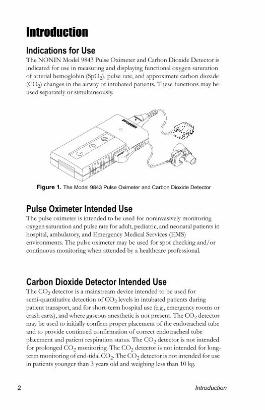
IntroductionIndications for UseThe NONIN Model 9843 Pulse Oximeter and Carbon Dioxide Detector is indicated for use in measuring and displaying functional oxygen saturation of arterial hemoglobin (SpO2), pulse rate, and approximate carbon dioxide (CO2) changes in the airway of intubated patients. These functions may be used separately or simultaneously.
Figure 1. The Model 9843 Pulse Oximeter and Carbon Dioxide Detector
Pulse Oximeter Intended UseThe pulse oximeter is intended to be used for noninvasively monitoring oxygen saturation and pulse rate for adult, pediatric, and neonatal patients in hospital, ambulatory, and Emergency Medical Services (EMS) environments. The pulse oximeter may be used for spot checking and/or continuous monitoring when attended by a healthcare professional.
Carbon Dioxide Detector Intended UseThe CO2 detector is a mainstream device intended to be used for semi-quantitative detection of CO2 levels in intubated patients during patient transport, and for short-term hospital use (e.g., emergency rooms or crash carts), and where gaseous anesthetic is not present. The CO2 detector may be used to initially confirm proper placement of the endotracheal tube and to provide continued confirmation of correct endotracheal tube placement and patient respiration status. The CO2 detector is not intended for prolonged CO2 monitoring. The CO2 detector is not intended for long-term monitoring of end-tidal CO2. The CO2 detector is not intended for use in patients younger than 3 years old and weighing less than 10 kg.
Introduction
P
1
Precautions for UseContraindications• Do not operate the Model 9843 in an MRI environment.• Do not use the Model 9843 in a situation where alarms are required.
The Model 9843 has no audible alarms.• Do not use the Model 9843 CO2 detector for patients less than 3
years old and under 10 kg due to the dead space introduced by the airway adapter tube.
• Do not use the Model 9843 CO2 detector during mouth-to-tube ventilation. The presence of CO2 in the exhaled breath from the person performing resuscitation will cause inaccurate readings.
• The Model 9843 CO2 detector cannot distinguish between oropharyngeal tube placement and endotracheal tube placement if the airway is patent. Standard clinical assessment must be used.
Warnings• Explosion hazard. Do not use the Model 9843 in the presence of
flammable anesthetics.• The Model 9843 is intended only as an adjunct in patient assessment.
It must be used in conjunction with other methods of assessing clinical signs and symptoms.
• As with all medical equipment, carefully route patient cabling to reduce the possibility of patient entanglement or strangulation.
• General operation of the Model 9843 may be affected by the use of an electrosurgical unit (ESU).
• Do not use a damaged sensor.• This device should not be used adjacent to or stacked with other
equipment. If adjacent or stacked use is necessary, the device should be observed carefully to verify normal operation.
• The use of accessories, sensors, and cables other than those specified in this manual may result in increased emission and/or decreased immunity of this device.
• Use only NONIN manufactured pulse oximeter sensors. These sensors are manufactured to meet the accuracy specifications for NONIN Pulse Oximeters. Using other manufacturer's sensors may cause improper pulse oximeter performance.
recautions for Use 3
4
1
• Check the pulse oximeter sensor application site frequently to determine the circulation, positioning, and skin sensitivity of the patient. Each patient's sensitivity to NONIN sensors may vary depending on their medical status or the condition of their skin.
• Discontinue use of the NONIN double-backed adhesive tape strips or the Hydrogel tape strips if the patient exhibits allergic reactions to the adhesive material.
• Do not stretch the adhesive tape while applying the pulse oximeter sensor. This may cause inaccurate readings or skin blisters.
• Do not reuse the Model 9840AAT Airway Adapter Tube.• If the airway adapter tube becomes contaminated or damaged, discard
it and replace it with a new one. Cleaning the interior will damage the anti-fog coating and cause inaccurate readings.
• The Model 9840AAT Airway Adapter Tube will increase dead space by approximately 6 cubic centimeters; this may adversely affect ventilation for patients with small tidal volumes.
• Do not use the airway adapter tube if the airway adapter tube is below 5 °C. An airway adapter tube that is below 5 °C may frost, causing a false reading. Warm the airway adapter tube to above 5 °C by putting it in a warm place (for example in your hands or in a vehicle) before use.
• If the Model 9843 CO2 detector results are inconclusive, the correct anatomic location of the endotracheal tube must be confirmed by other methods.
• Do not use the Model 9843 CO2 detector with a humidifier or nebulizer in the breathing circuit, as the fine mist may cause erroneous readings.
Cautions• Federal law (USA) restricts this device to sale by or on the order of a
physician.• Read this manual carefully before using the Model 9843.• Before use, carefully read the package insert provided with the sensors.• Model 9843 Pulse Oximeter and Carbon Dioxide Detectors are
sensitive electronic instruments and must be repaired by knowledgeable and specially trained personnel only.
• Ensure that the Model 9843, the airway adapter tube, and the sensors have stabilized at the specified environmental operating conditions before use.
• Verify that all audible and visible indications are operating properly during the power on self-test. If any self-test event does not occur or functions incorrectly, do not use the Model 9843. Consult the troubleshooting guide or contact NONIN Customer Support.
Precautions for Use
P
1
• Do not immerse the Model 9843 or NONIN sensors in liquid.• Do not use caustic or abrasive cleaning agents on the Model 9843 or
the sensors.• Do not use different types of batteries at the same time. Do not mix
fully charged and partially charged batteries at the same time. These actions may cause the batteries to leak.
• Do not remove any covers other than the battery cover when replacing batteries. There are no user serviceable parts inside other than the replaceable batteries.
• Follow local governing ordinances and recycling instructions regarding disposal or recycling of device components, including batteries.
• Alkaline batteries may leak or explode if used or disposed of improperly.
• Do not block the audible indicator speaker holes. Blocking the speakers will significantly reduce the sound volume.
• This equipment complies with International Standard EN 60601-1-2:2001 for electromagnetic compatibility for medical electrical equipment and/or systems. This standard is designed to provide reasonable protection against harmful interference in a typical medical installation. However, because of the proliferation of radio-frequency transmitting equipment and other sources of electrical noise in healthcare and other environments, it is possible that high levels of such interference due to close proximity or strength of a source might disrupt the performance of this device. Medical electrical equipment needs special precautions regarding EMC, and all equipment must be installed and put into service according to the EMC information specified in this manual.
• Portable and mobile RF communications equipment can affect medical electrical equipment.
• The Model 9843 pulse oximeter is intended for spot checking or monitoring by an attending healthcare professional. Because the Model 9843 has no audible alarms, international labeling requirements (EN 865) dictate it be labeled “Not for Continuous Monitoring.”
• The Model 9843 pulse oximeter must be able to measure the pulse properly to obtain an accurate SpO2 measurement. Verify that nothing is hindering the pulse measurement before relying on the SpO2 measurement.
• The Model 9843 pulse oximeter may not work on all patients. If you are unable to achieve stable readings, discontinue use.
recautions for Use 5
6
1
• The Model 9843 pulse oximeter may interpret motion artifact as good pulse quality.
• The Model 9843 pulse oximeter is designed to determine the percentage of arterial oxygen saturation of functional hemoglobin. Significant levels of dysfunctional hemoglobin such as carboxyhemoglobin or methemoglobin may affect the accuracy of the measurement.
• Cardiogreen and other intravascular dyes, depending on the concentration, may affect the accuracy of the SpO2 measurement.
• Some fingernail polish colors (particularly blues and blacks) may reduce light transmission and thereby affect SpO2 accuracy.
• Ear Clip and Reflectance pulse oximeter sensors are not recommended for pediatric or neonatal use. The accuracy of these sensors has not been established for pediatric or neonatal use.
• Remove earrings from the patient’s ear before applying the Ear Clip Sensor.
• Water or other liquid between the airway adapter tube and the CO2sensor may cause erroneous readings.
• Ensure that all connections to the airway adapter tube are tight and leak-free, and that the airway adapter tube is properly attached to the CO2 sensor.
• An airway adapter tube that is between 5 °C and 10 °C may cause inaccurate readings due to fogging of optical surfaces. It is recommended that the airway adapter tube be warmed to above 10°C before use.
• Gastric distention with air prior to intubation may introduce CO2 into the stomach and esophagus and yield false results. Observe six breaths before interpreting results.
• This device has not been tested for immunity to electromagnetic disturbances.
• The Model 9843 CO2 detector should not be used with gaseous anesthetics.
• In compliance with the European Directive on Waste Electrical and Electronic Equipment (WEEE) 2002/96/EC, do not dispose of this product as unsorted municipal waste. This device contains WEEE materials; please contact your distributor regarding take-back or recycling of the device. If you are unsure how to reach your distributor, please call Nonin for your distributor’s contact information.
Precautions for Use
P
1
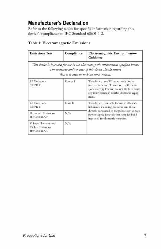
Manufacturer’s DeclarationRefer to the following tables for specific information regarding this device’s compliance to IEC Standard 60601-1-2.
Table 1: Electromagnetic Emissions
Emissions Test Compliance Electromagnetic Environment—Guidance
This device is intended for use in the electromagnetic environment specified below. The customer and/or user of this device should ensure
that it is used in such an environment.
RF EmissionsCISPR 11
Group 1 This device uses RF energy only for its internal function. Therefore, its RF emis-sions are very low and are not likely to cause any interference in nearby electronic equip-ment.
RF EmissionsCISPR 11
Class B This device is suitable for use in all estab-lishments, including domestic and those directly connected to the public low-voltage power supply network that supplies build-ings used for domestic purposes.
Harmonic EmissionsIEC 61000-3-2
N/A
Voltage Fluctuations/Flicker EmissionsIEC 61000-3-3
N/A
recautions for Use 7
8
1
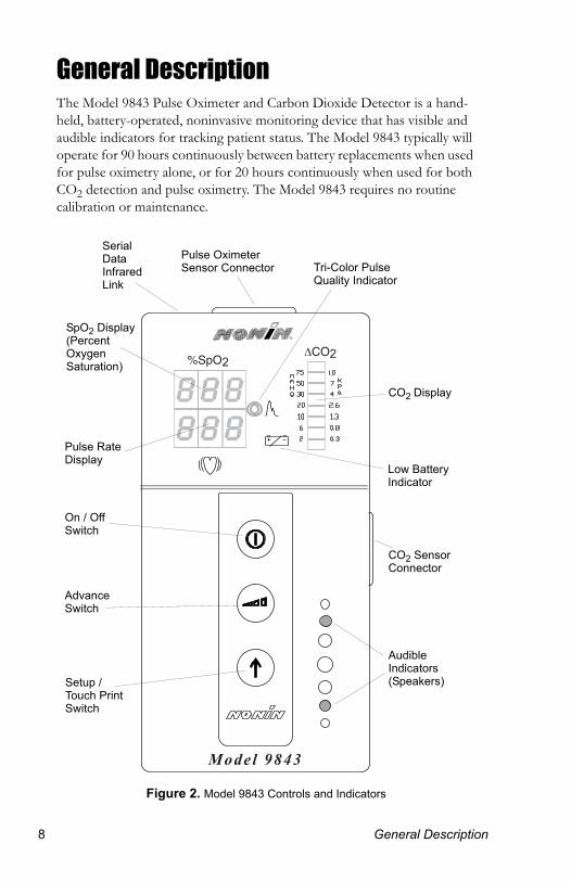
General DescriptionThe Model 9843 Pulse Oximeter and Carbon Dioxide Detector is a hand-held, battery-operated, noninvasive monitoring device that has visible and audible indicators for tracking patient status. The Model 9843 typically will operate for 90 hours continuously between battery replacements when used for pulse oximetry alone, or for 20 hours continuously when used for both CO2 detection and pulse oximetry. The Model 9843 requires no routine calibration or maintenance.
Figure 2. Model 9843 Controls and Indicators
CO%SpO
SpO2 Display (Percent Oxygen Saturation)
CO2 Sensor Connector
Audible Indicators (Speakers)
On / Off Switch
Advance Switch
Setup / Touch Print Switch
Tri-Color Pulse Quality Indicator
CO2 Display
Pulse Rate Display
Low Battery Indicator
Serial Data Infrared Link
Pulse Oximeter Sensor Connector
General Description
G
1
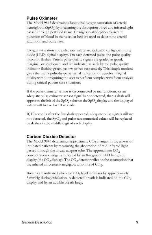
Pulse OximeterThe Model 9843 determines functional oxygen saturation of arterial hemoglobin (SpO2) by measuring the absorption of red and infrared light passed through perfused tissue. Changes in absorption caused by pulsation of blood in the vascular bed are used to determine arterial saturation and pulse rate.
Oxygen saturation and pulse rate values are indicated on light-emitting diode (LED) digital displays. On each detected pulse, the pulse quality indicator flashes. Patient pulse quality signals are graded as good, marginal, or inadequate and are indicated as such by the pulse quality indicator flashing green, yellow, or red respectively. This simple method gives the user a pulse-by-pulse visual indication of waveform signal quality without requiring the user to perform complex waveform analysis during critical patient care situations.
If the pulse oximeter sensor is disconnected or malfunctions, or an adequate pulse oximeter sensor signal is not detected, then a dash will appear to the left of the SpO2 value on the SpO2 display and the displayed values will freeze for 10 seconds.
If, 10 seconds after the first dash appeared, adequate pulse signals still are not detected, the SpO2 and pulse rate numerical values will be replaced by dashes in the middle digit of each display.
Carbon Dioxide DetectorThe Model 9843 determines approximate CO2 changes in the airway of intubated patients by measuring the absorption of mid-infrared light passed through the airway adapter tube. The approximate CO2 concentration change is indicated by an 8-segment LED bar graph display (the CO2 display). The CO2 detector relies on the assumption that the inhaled air contains negligible amounts of CO2.
Breaths are indicated when the CO2 level increases by approximately 5 mmHg during exhalation. A detected breath is indicated on the CO2 display and by an audible breath beep.
eneral Description 9

1
1
If the CO2 sensor is initially connected and operating and then:
• the CO2 sensor is unplugged, or• the airway adapter tube is removed from the CO2 sensor, or• the light path is blocked, or• a CO2 sensor failure occurs,
then the third and sixth bars on the CO2 display will be steadily illuminated. This visible indication is defined as a CO2 sensor fault.
Unpacking Your Model 9843Contact the carrier immediately if the shipping carton for the Model 9843 is damaged. Carefully unpack the instrument and its accessories. Confirm that the items listed below are packed with the Model 9843 Pulse Oximeter and Carbon Dioxide Detector.
The Model 9843 complete system includes:
n 1 Model 9843 Pulse Oximeter and Carbon Dioxide Detector n 1 Operator’s Manual for the Model 9843n 1 Model 8000AA-1 Adult Articulated Finger Clip Sensorn 1 Model 9840SA Carbon Dioxide Sensorn 3 Model 9840AAT Airway Adapter Tubesn 6 AA Size Alkaline Batteries
If any item on this list is missing or damaged, contact your local distributor.
0 General Description
B
1
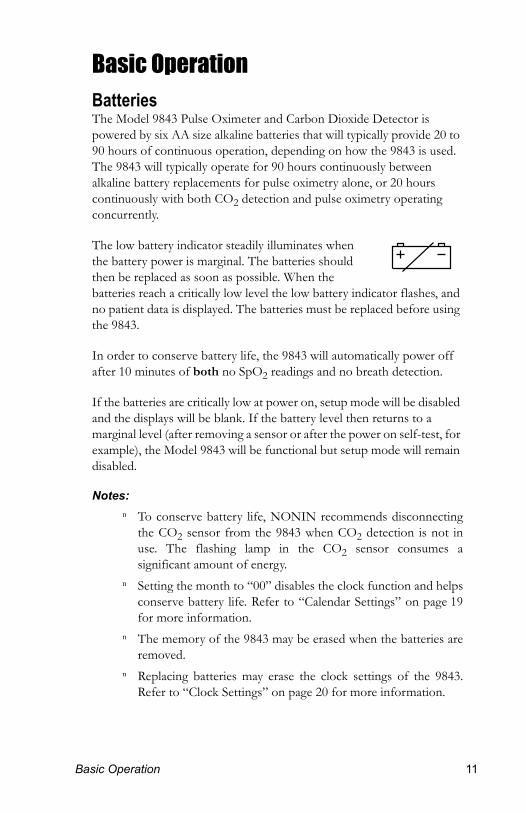
Basic OperationBatteriesThe Model 9843 Pulse Oximeter and Carbon Dioxide Detector is powered by six AA size alkaline batteries that will typically provide 20 to 90 hours of continuous operation, depending on how the 9843 is used. The 9843 will typically operate for 90 hours continuously between alkaline battery replacements for pulse oximetry alone, or 20 hours continuously with both CO2 detection and pulse oximetry operating concurrently.
The low battery indicator steadily illuminates when the battery power is marginal. The batteries should then be replaced as soon as possible. When the batteries reach a critically low level the low battery indicator flashes, and no patient data is displayed. The batteries must be replaced before using the 9843.
In order to conserve battery life, the 9843 will automatically power off after 10 minutes of both no SpO2 readings and no breath detection.
If the batteries are critically low at power on, setup mode will be disabled and the displays will be blank. If the battery level then returns to a marginal level (after removing a sensor or after the power on self-test, for example), the Model 9843 will be functional but setup mode will remain disabled.
Notes: n To conserve battery life, NONIN recommends disconnecting
the CO2 sensor from the 9843 when CO2 detection is not in use. The flashing lamp in the CO2 sensor consumes a significant amount of energy.
n Setting the month to “00” disables the clock function and helps conserve battery life. Refer to “Calendar Settings” on page 19for more information.
n The memory of the 9843 may be erased when the batteries are removed.
n Replacing batteries may erase the clock settings of the 9843. Refer to “Clock Settings” on page 20 for more information.
asic Operation 11
1
1
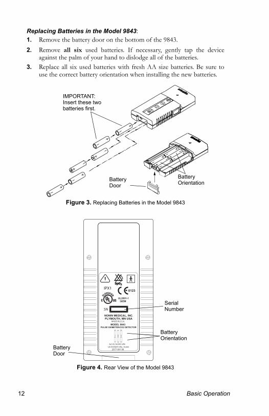
Replacing Batteries in the Model 9843:1. Remove the battery door on the bottom of the 9843.2. Remove all six used batteries. If necessary, gently tap the device
against the palm of your hand to dislodge all of the batteries.3. Replace all six used batteries with fresh AA size batteries. Be sure to
use the correct battery orientation when installing the new batteries.
Figure 3. Replacing Batteries in the Model 9843
Figure 4. Rear View of the Model 9843
IMPORTANT: Insert these two batteries first.
Battery OrientationBattery
Door
Serial Number
Battery Door
Battery Orientation
SN
2577-001 06US PATENT # Re. 33,643
6x1.5V AA IEC LR6
UL2601-130EM
PULSE OXIMETER/CO2 DETECTOR
MODEL 9843
PLYMOUTH, MN USANONIN MEDICAL, INC.
0123IPX1
MADE IN U.S.A.
2 Basic Operation
B
1
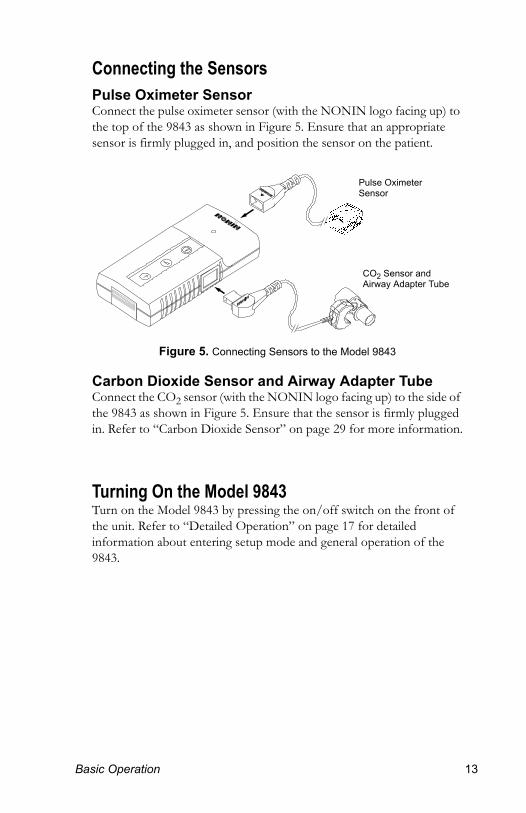
Connecting the SensorsPulse Oximeter SensorConnect the pulse oximeter sensor (with the NONIN logo facing up) to the top of the 9843 as shown in Figure 5. Ensure that an appropriate sensor is firmly plugged in, and position the sensor on the patient.
Figure 5. Connecting Sensors to the Model 9843
Carbon Dioxide Sensor and Airway Adapter TubeConnect the CO2 sensor (with the NONIN logo facing up) to the side of the 9843 as shown in Figure 5. Ensure that the sensor is firmly plugged in. Refer to “Carbon Dioxide Sensor” on page 29 for more information.
Turning On the Model 9843Turn on the Model 9843 by pressing the on/off switch on the front of the unit. Refer to “Detailed Operation” on page 17 for detailed information about entering setup mode and general operation of the 9843.
Pulse Oximeter Sensor
CO2 Sensor and Airway Adapter Tube
asic Operation 13
1
1
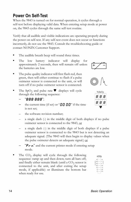
Power On Self-TestWhen the 9843 is turned on for normal operation, it cycles through a self-test before displaying valid data. When entering setup mode at power on, the 9843 cycles through the same self-test routine.
Verify that all audible and visible indications are operating properly during the power on self-test. If any self-test event does not occur or functions incorrectly, do not use the 9843. Consult the troubleshooting guide or contact NONIN Customer Support.
• The audible breath beep will sound three times.
• The low battery indicator will display for approximately 2 seconds, then will remain off unless the batteries are low.
• The pulse quality indicator will first flash red, then green, then will either continue to flash if a pulse oximeter sensor is connected to the unit, or will turn off if no pulse oximeter sensor is connected.
• The SpO2 and pulse rate ♥ displays will cycle through the following sequence:– “888 888”;– the current time (if set) or “00 00” if the time
is not set;– the software revision number;– a single dash (-) in the middle digit of both displays if no pulse
oximeter sensor is connected to the 9843, or– a single dash (-) in the middle digit of both displays if a pulse
oximeter sensor is connected to the 9843 but is not detecting an adequate signal. (The 9843 will then begin to display values when the pulse oximeter detects an adequate signal.) or
– “Prn” and the current printer mode if entering setup mode.
• The CO2 display will cycle through the following sequence: ramp up and then down; turn all bars off; and finally either remain blank (until a CO2 sensor is connected to the unit, and after exiting the setup mode, if applicable) or illuminate the bottom bar when ready for use.
mmHg
kPa
75
30
50
2
6
10
20
10
4
7
0.3
0.8
1.3
2.6
4 Basic Operation

B
1
Overview of MonitoringPulse OximeterVerify that the sensor is properly positioned, and ensure that the pulse oximeter is sensing adequate pulse quality by:
• verifying that the pulse quality indicator ( ) is flashing green and• verifying that the pulse rate (♥) and SpO2 (%SpO2) displays are
showing readings and• verifying that the pulse quality indicator flashing is correlated to the
pulse rate for at least 10 seconds
If the pulse quality indicator light is flashing red or yellow or is flashing erratically, reposition the pulse oximeter sensor or try a different sensor.
If no pulse oximeter sensor is attached to the pulse oximeter after system initialization (a few seconds after powering on), only a dash ( - ) will be displayed in the middle segment of both the SpO2 and pulse rate ♥ displays.
Carbon Dioxide DetectorVerify that the airway adapter tube is properly attached to the CO2 sensor and that the CO2 sensor is properly connected to the 9843. Next, verify that the lower bar of the CO2 display is illuminated and the lamp inside the CO2 sensor is flashing on and off. (When CO2 is detected, the illuminated bars on the CO2 display will indicate the approximate change in CO2 level.)
Attach the CO2 sensor/airway adapter tube assembly to the patient’s endotracheal tube. The CO2 detector will reflect appropriate values and breath beeps for each breath (if the breath beep sound volume is not set to “off ”).
If the CO2 sensor is initially connected and operating and then the CO2 sensor is unplugged, the airway adapter tube is removed from the CO2 sensor, the light path is blocked, or a CO2 sensor failure occurs, then the third and sixth bars of the CO2 display will be illuminated indicating a CO2 sensor fault.
asic Operation 15
1
1
Cleaning the Model 9843CAUTION! Do not immerse the 9843 or sensors in liquid.
CAUTION! Do not use caustic or abrasive cleaning agents.
Clean the 9843 unit separately from the sensors. Refer to the appropriate cleaning instructions for each sensor type.
Notes:
• For instructions on cleaning pulse oximeter sensors, refer to the respective pulse oximeter sensor instruction inserts.
• For instructions on cleaning the CO2 sensor refer to “Cleaning the Carbon Dioxide Sensor” on page 30.
Cleaning the 9843
ä Clean the 9843 (device only) with a soft cloth dampened with isopropyl alcohol. Do not pour or spray any liquids onto the 9843, and do not allow any liquid to enter any openings in the device. Allow the 9843 to dry thoroughly before reusing.
6 Basic Operation
D
1
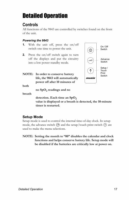
Detailed OperationControlsAll functions of the 9843 are controlled by switches found on the front of the unit.
Powering the 98431. With the unit off, press the on/off
switch one time to power the unit.
2. Press the on/off switch again to turn off the displays and put the circuitry into a low power standby mode.
NOTE: In order to conserve battery life, the 9843 will automatically power off after 10 minutes of
both no SpO2 readings and no
breath detection. Each time an SpO2 value is displayed or a breath is detected, the 10-minute timer is restarted.
Setup ModeSetup mode is used to control the internal time-of-day clock. In setup mode, the advance switch and the setup/touch print switch are used to make the menu selections.
NOTE: Setting the month to “00” disables the calendar and clock functions and helps conserve battery life. Setup mode will be disabled if the batteries are critically low at power on.
On / Off Switch
Advance Switch
Setup / Touch Print Switch
etailed Operation 17
1
1
Entering Setup Mode1. With the unit off, press and hold the setup/touch print switch while
pressing and then releasing the on/off switch.
2. Release the setup/touch print switch when “888 888” is displayed on the SpO2 and pulse rate ♥ displays. Three brief beeps will sound, and “Prn” will appear in the SpO2 display.
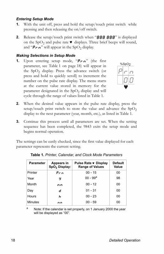
Making Selections in Setup Mode1. Upon entering setup mode, “Prn” (the first
parameter, see Table 1 on page 18) will appear in the SpO2 display. Press the advance switch (or press and hold to quickly scroll) to increment the number on the pulse rate display. The menu starts at the current value stored in memory for the parameter designated in the SpO2 display and will cycle through the range of values listed in Table 1.
2. When the desired value appears in the pulse rate display, press the setup/touch print switch to store the value and advance the SpO2display to the next parameter (year, month, etc.), as listed in Table 1.
3. Continue this process until all parameters are set. When the setting sequence has been completed, the 9843 exits the setup mode and begins normal operation.
The settings can be easily checked, since the first value displayed for each parameter represents the current setting.
Table 1. Printer, Calendar, and Clock Mode Parameters
Parameter Appears in SpO2 Display:
Pulse Rate ♥ DisplayRange of Values
Default Value
Printer Prn 00 - 15 00
Year y 00 - 99a
a Note: If the calendar is set properly, on 1 January 2000 the year will be displayed as “00”.
98
Month nn 00 - 12 00
Day d 01 - 31 00
Hours h 00 - 23 00
Minutes nn 00 - 59 00
8 Detailed Operation
D
1
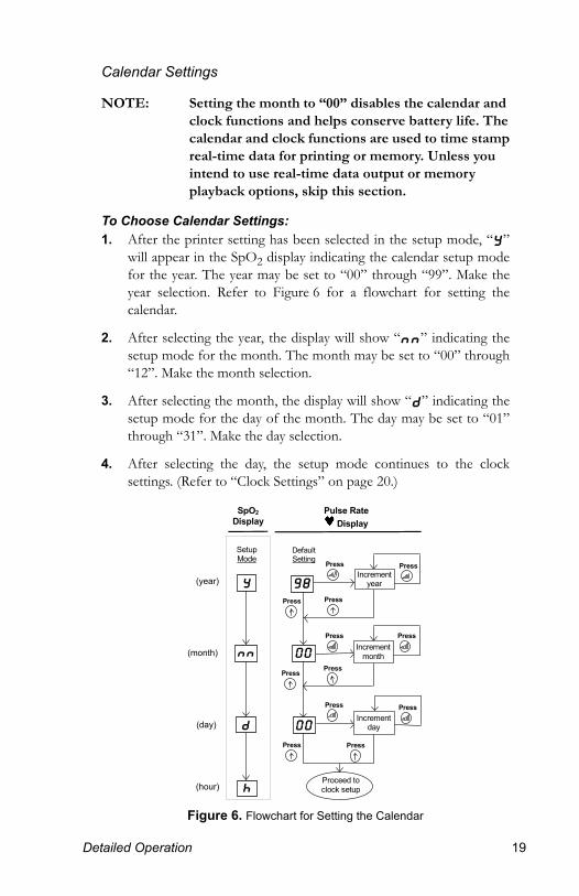
Calendar Settings
NOTE: Setting the month to “00” disables the calendar and clock functions and helps conserve battery life. The calendar and clock functions are used to time stamp real-time data for printing or memory. Unless you intend to use real-time data output or memory playback options, skip this section.
To Choose Calendar Settings:1. After the printer setting has been selected in the setup mode, “y”
will appear in the SpO2 display indicating the calendar setup mode for the year. The year may be set to “00” through “99”. Make the year selection. Refer to Figure 6 for a flowchart for setting the calendar.
2. After selecting the year, the display will show “nn” indicating the setup mode for the month. The month may be set to “00” through “12”. Make the month selection.
3. After selecting the month, the display will show “d” indicating the setup mode for the day of the month. The day may be set to “01” through “31”. Make the day selection.
4. After selecting the day, the setup mode continues to the clock settings. (Refer to “Clock Settings” on page 20.)
Figure 6. Flowchart for Setting the Calendar
Pulse Rate Display
DefaultSetting
SpO2Display
SetupMode
Incrementyear
Incrementmonth
Incrementday
Proceed toclock setup
Press Press
Press Press
Press Press
Press Press
Press Press
Press Press
98
00
00
y
nn
d
h
(year)
(month)
(day)
(hour)
etailed Operation 19
2
1
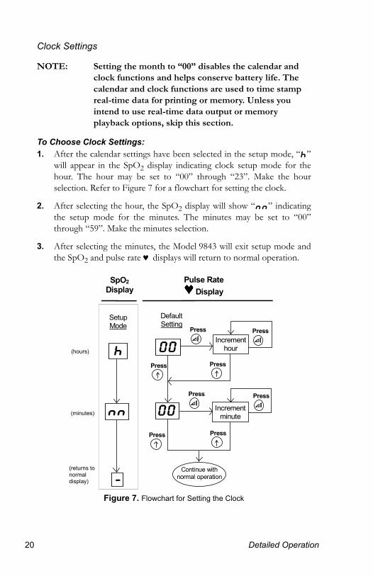
Clock Settings
NOTE: Setting the month to “00” disables the calendar and clock functions and helps conserve battery life. The calendar and clock functions are used to time stamp real-time data for printing or memory. Unless you intend to use real-time data output or memory playback options, skip this section.
To Choose Clock Settings:1. After the calendar settings have been selected in the setup mode, “h”
will appear in the SpO2 display indicating clock setup mode for the hour. The hour may be set to “00” through “23”. Make the hour selection. Refer to Figure 7 for a flowchart for setting the clock.
2. After selecting the hour, the SpO2 display will show “nn” indicating the setup mode for the minutes. The minutes may be set to “00” through “59”. Make the minutes selection.
3. After selecting the minutes, the Model 9843 will exit setup mode and the SpO2 and pulse rate ♥ displays will return to normal operation.
Figure 7. Flowchart for Setting the Clock
Pulse Rate Display
DefaultSetting
SpO2Display
SetupMode
Incrementhour
Incrementminute
Press Press
Press Press
Press
Continue withnormal operation
00
00
h
nn
-
Press
Press Press
(hours)
(returns to normal display)
(minutes)
0 Detailed Operation
D
1
IndicatorsRefer to Figure 2 on page 8 for a detailed illustration of the Model 9843 controls and indicators.
Visible Indicators
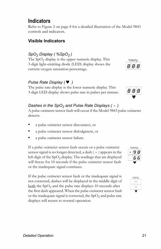
SpO2 Display ( %SpO2 )The SpO2 display is the upper numeric display. This 3-digit light-emitting diode (LED) display shows the current oxygen saturation percentage.
Pulse Rate Display ( ♥ )The pulse rate display is the lower numeric display. This 3-digit LED display shows pulse rate in pulses per minute.
Dashes in the SpO2 and Pulse Rate Displays ( - )A pulse oximeter sensor fault will occur if the Model 9843 pulse oximeter detects:
• a pulse oximeter sensor disconnect, or• a pulse oximeter sensor dislodgment, or• a pulse oximeter sensor failure.
If a pulse oximeter sensor fault occurs or a pulse oximeter sensor signal is no longer detected, a dash ( - ) appears in the left digit of the SpO2 display. The readings that are displayed will freeze for 10 seconds if the pulse oximeter sensor fault or the inadequate signal continues.
If the pulse oximeter sensor fault or the inadequate signal is not corrected, dashes will be displayed in the middle digit of both the SpO2 and the pulse rate displays 10 seconds after the first dash appeared. When the pulse oximeter sensor fault or the inadequate signal is corrected, the SpO2 and pulse rate displays will return to normal operation.
etailed Operation 21
2
1
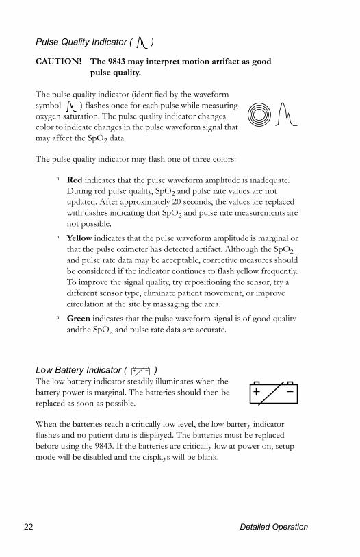
Pulse Quality Indicator ( )
CAUTION! The 9843 may interpret motion artifact as good pulse quality.
The pulse quality indicator (identified by the waveform symbol ) flashes once for each pulse while measuring oxygen saturation. The pulse quality indicator changes color to indicate changes in the pulse waveform signal that may affect the SpO2 data.
The pulse quality indicator may flash one of three colors:
n Red indicates that the pulse waveform amplitude is inadequate. During red pulse quality, SpO2 and pulse rate values are not updated. After approximately 20 seconds, the values are replaced with dashes indicating that SpO2 and pulse rate measurements are not possible.
n Yellow indicates that the pulse waveform amplitude is marginal or that the pulse oximeter has detected artifact. Although the SpO2 and pulse rate data may be acceptable, corrective measures should be considered if the indicator continues to flash yellow frequently. To improve the signal quality, try repositioning the sensor, try a different sensor type, eliminate patient movement, or improve circulation at the site by massaging the area.
n Green indicates that the pulse waveform signal is of good quality andthe SpO2 and pulse rate data are accurate.
Low Battery Indicator ( )The low battery indicator steadily illuminates when the battery power is marginal. The batteries should then be replaced as soon as possible.
When the batteries reach a critically low level, the low battery indicator flashes and no patient data is displayed. The batteries must be replaced before using the 9843. If the batteries are critically low at power on, setup mode will be disabled and the displays will be blank.
2 Detailed Operation

D
1
CO2 Display ( Δ CO2 )The CO2 display will remain blank until the CO2 sensor is plugged in. When an airway adapter tube is connected to the CO2 sensor and an adequate signal is detected, the bottom bar is initially illuminated. Additional bars will be illuminated to indicate an increase in CO2 level as the patient exhales through the airway adapter tube.
If, after an adequate signal has been detected:
• the CO2 sensor is unplugged, or• the airway adapter tube is removed from
the CO2 sensor, or• the light path is blocked, or• a CO2 sensor failure occurs,
then a CO2 sensor fault exists. The third and sixth bars of the CO2 display will be illuminated. When the sensor fault is corrected, the CO2 display will return to normal operation.
CO2 values are displayed as a range between two threshold values. The threshold values are located between each CO2 display bar. The values (displayed in both mmHg and kPa) are an approximate (semi-quantitative) measurement of the change in CO2 level (Δ CO2) in the airway adapter tube.
For example, if four bars are illuminated, the detected CO2 level change lies within the range ≥10 mmHg and <20 mmHg (the threshold values).
CAUTION! Because the CO2 detector is a semi-quantitative device, the rising and falling CO2 display (the bar graph) should NOT be interpreted as a CO2 waveform.
mmHg
kPa
75
30
50
2
6
10
20
10
4
7
0.3
0.8
1.3
2.6
Bottom Bar
mmHg
kPa
75
30
50
2
6
10
20
10
4
7
0.3
0.8
1.3
2.6
Sixth Bar
Third Bar
mmHg
kPa
75
30
50
2
6
10
20
10
4
7
0.3
0.8
1.3
2.6
Threshold Values
etailed Operation 23
2
1
Audible Indicators
CAUTION! Do not use the 9843 in situations where alarms are required. The 9843 has no audible alarms.
CAUTION! Do not block the audible indicator speaker holes. Blocking the speakers will significantly reduce the sound volume.
Audible Breath BeepWhen the detected CO2 increases (during exhalation) by approximately 5 mmHg, a breath is detected and the audible breath beep will sound. One beep is sounded for each breath detected.
Each time the 9843 is turned on, the audible breath beep will default to the medium sound volume setting. During normal operation, pressing the advance switch cycles the audible breath beep sound volume between low, medium, high, and off. A “volume” beep will sound each time the advance switch is pressed to indicate the current setting.
4 Detailed Operation
D
1
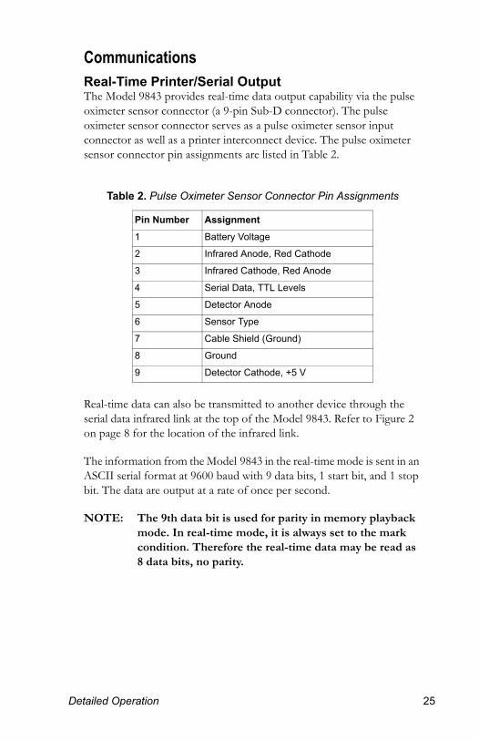
CommunicationsReal-Time Printer/Serial OutputThe Model 9843 provides real-time data output capability via the pulse oximeter sensor connector (a 9-pin Sub-D connector). The pulse oximeter sensor connector serves as a pulse oximeter sensor input connector as well as a printer interconnect device. The pulse oximeter sensor connector pin assignments are listed in Table 2.
Real-time data can also be transmitted to another device through the serial data infrared link at the top of the Model 9843. Refer to Figure 2 on page 8 for the location of the infrared link.
The information from the Model 9843 in the real-time mode is sent in an ASCII serial format at 9600 baud with 9 data bits, 1 start bit, and 1 stop bit. The data are output at a rate of once per second.
NOTE: The 9th data bit is used for parity in memory playback mode. In real-time mode, it is always set to the mark condition. Therefore the real-time data may be read as 8 data bits, no parity.
Table 2. Pulse Oximeter Sensor Connector Pin Assignments
Pin Number Assignment
1 Battery Voltage
2 Infrared Anode, Red Cathode
3 Infrared Cathode, Red Anode
4 Serial Data, TTL Levels
5 Detector Anode
6 Sensor Type
7 Cable Shield (Ground)
8 Ground
9 Detector Cathode, +5 V
etailed Operation 25
2
1
Real-time data may be printed or displayed. On power up a header is sent identifying the format and the time and date. Thereafter, the data are sent once per second by the Model 9843 in the following format:
HH:MM:SS SPO2=XXX HR=YYY
where “HH” represents the hour the real-time clock is set to, “MM” represents the minutes, “SS” represents the seconds, “XXX” represents the SpO2 value, and “YYY” represents the pulse rate. The SpO2 and pulse rate will be displayed as “---” if there are no data available for the data reading.
If a breath was detected in the previous interval a “B” will be appended to the data line and will be printed by some devices.
6 Detailed Operation
D
1
MemoryThe Model 9843 can collect and store up to 18 hours of SpO2 and pulse rate information.
Nonin offers nVISION® Data Management Software for Oximetry Screening, for use with a personal computer. nVISION is an easy to use Windows®-based program for pulse oximetry data retrieval, analysis, report generation, and data storage. Refer to “Accessories” on page 38.
The solid-state memory in the Model 9843 functions much like an endless loop. When the memory fills up, the unit begins overwriting the oldest locations with the latest data.
Each time the Model 9843 is turned on, the current time/date information (if the clock is set properly) is stored in memory to allow quick differentiation of recording sessions. Patient SpO2 and pulse rate are sampled and stored every four seconds. The oxygen saturation values are stored in 1% increments in the range of 0 to 100%. The stored pulse rate ranges from 18 to 300 pulses per minute. The stored values have increments of 1 pulse per minute from 18 to 200 pulses per minute, and increments of 2 pulses per minute from 201 to 300 pulses per minute.
NOTE: CO2 detector data are not stored in memory.
During printing of the data, the last data recorded are the first data printed. For example, the last four minutes of data recorded would be the first four minutes of printout.
Recording SessionsEach time the Model 9843 is turned on (except while setting the clock) data are automatically collected.
NOTE: Only recording sessions greater than one minute in length are kept in memory for later printing.
etailed Operation 27

2
1
Memory Playback Mode
Playing Back Data Stored in Memory1. With the unit off, press and hold the setup/touch print switch while
pressing and then releasing the on/off switch.
2. Release the setup/touch print switch when “888 888” is displayed on the SpO2 and pulse rate displays. Three brief beeps will sound and “Prn” will appear in the SpO2 display.
3. Data will automatically be played back from the memory.
NOTE: The keypad sequence for starting memory playback is identical to the sequence used for entering setup mode.
Data are played back at a rate of 20 minutes of collected data per second. An 18-hour recording session (the maximum memory saved) is played back in approximately 1 minute. After all data are played back, the 9843 should be shut off before collecting new patient data. The patient information is held in memory as long as the batteries are good, so if the memory must be cleared, remove the batteries for a period of 60 seconds or longer. Playing back the data in memory does not clear any data from the memory.
The size of this file will depend on the amount of data saved in the memory. The most recent data are played back first. The memory data format is in binary. Bad data is represented by FF (hexadecimal) or 255 (decimal). If the memory “wrapped around” (the recording time exceeded 18 hours) and the final (i.e., the oldest) file of data has been truncated, the final start time will be represented by zeroes and the start times for that file will then not match up.
8 Detailed Operation
C
1
Carbon Dioxide Sensor and Airway Adapter TubeWARNING! The Model 9840AAT Airway Adapter Tube will
increase dead space by approximately 6 cubic centimeters, which may adversely affect ventilation for patients with small tidal volumes.
WARNING! Do not use a damaged sensor.
CAUTION! Before use, carefully read the instruction insert provided with the sensors.
CAUTION! Water or other liquid between the airway adapter tube and the CO2 sensor may cause erroneous readings.
CAUTION! Ensure that all connections to the airway adapter tube are tight and leak-free, and that the airway adapter tube is properly attached to the CO2 sensor.
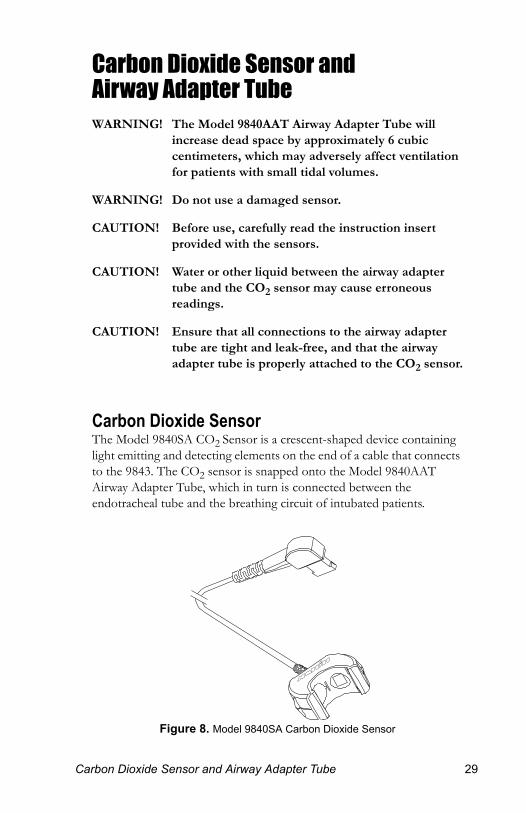
Carbon Dioxide SensorThe Model 9840SA CO2 Sensor is a crescent-shaped device containing light emitting and detecting elements on the end of a cable that connects to the 9843. The CO2 sensor is snapped onto the Model 9840AAT Airway Adapter Tube, which in turn is connected between the endotracheal tube and the breathing circuit of intubated patients.
Figure 8. Model 9840SA Carbon Dioxide Sensor
arbon Dioxide Sensor and Airway Adapter Tube 29

3
1
Cleaning the Carbon Dioxide SensorCAUTION! Do not immerse the CO2 sensor in liquid, and do not
use caustic or abrasive cleaning agents on the CO2 sensor.
The CO2 sensor is protected against splashing water.
Cleaning the CO2 Sensor
ä Clean the Model 9840SA CO2 Sensor with a soft cloth dampened with isopropyl alcohol or a commonly used disinfectant. Do not pour or spray any liquids onto the Model 9840SA CO2 Sensor. Allow the Model 9840SA CO2 Sensor to dry thoroughly before reusing.
Returning the CO2 Sensor for ServiceIf the Model 9840SA CO2 Sensor must be returned to NONIN for service, the product should be free of any contaminants, and sterilization may be required. Contact NONIN’s Customer Support department for shipping instructions.
0 Carbon Dioxide Sensor and Airway Adapter Tube
C
1
Airway Adapter TubeWARNING! Do not reuse the Model 9840AAT Airway Adapter
Tube.
WARNING! If the airway adapter tube becomes contaminated or damaged, discard it and replace it with a new one. Cleaning the interior will damage the anti-fog coating and cause inaccurate readings.
WARNING! Do not use the airway adapter tube if it is below 5°C. An airway adapter tube that is below 5°C may frost, causing a false reading. Warm the airway adapter tube to above 5°C by warming it before use.
CAUTION! An airway adapter tube that is between 5°C and 10°C may cause inaccurate readings due to fogging of optical surfaces. Warm the airway adapter tube to above 10°C before use.
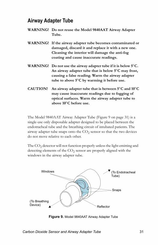
The Model 9840AAT Airway Adapter Tube (Figure 9 on page 31) is a single-use only disposable adapter designed to be placed between the endotracheal tube and the breathing circuit of intubated patients. The airway adapter tube snaps onto the CO2 sensor so that the two devices do not move relative to each other.
The CO2 detector will not function properly unless the light emitting and detecting elements of the CO2 sensor are properly aligned with the windows in the airway adapter tube.
Figure 9. Model 9840AAT Airway Adapter Tube
Windows
Snaps
(To Breathing Device)
(To Endotracheal Tube)
Reflector
arbon Dioxide Sensor and Airway Adapter Tube 31
3
1
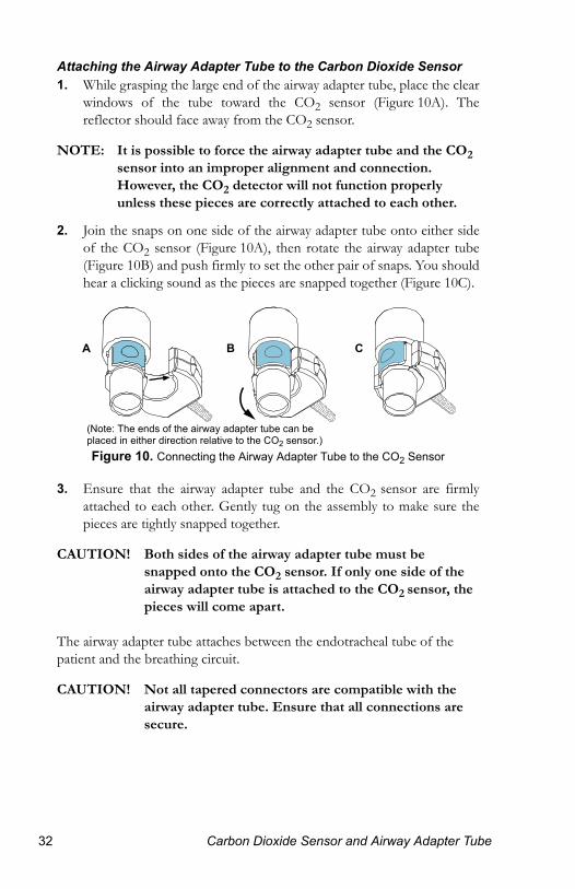
Attaching the Airway Adapter Tube to the Carbon Dioxide Sensor1. While grasping the large end of the airway adapter tube, place the clear
windows of the tube toward the CO2 sensor (Figure 10A). The reflector should face away from the CO2 sensor.
NOTE: It is possible to force the airway adapter tube and the CO2 sensor into an improper alignment and connection. However, the CO2 detector will not function properly unless these pieces are correctly attached to each other.
2. Join the snaps on one side of the airway adapter tube onto either side of the CO2 sensor (Figure 10A), then rotate the airway adapter tube (Figure 10B) and push firmly to set the other pair of snaps. You should hear a clicking sound as the pieces are snapped together (Figure 10C).
Figure 10. Connecting the Airway Adapter Tube to the CO2 Sensor
3. Ensure that the airway adapter tube and the CO2 sensor are firmly attached to each other. Gently tug on the assembly to make sure the pieces are tightly snapped together.
CAUTION! Both sides of the airway adapter tube must be snapped onto the CO2 sensor. If only one side of the airway adapter tube is attached to the CO2 sensor, the pieces will come apart.
The airway adapter tube attaches between the endotracheal tube of the patient and the breathing circuit.
CAUTION! Not all tapered connectors are compatible with the airway adapter tube. Ensure that all connections are secure.
(Note: The ends of the airway adapter tube can be placed in either direction relative to the CO2 sensor.)
BA C
2 Carbon Dioxide Sensor and Airway Adapter Tube
C
1
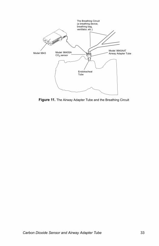
Figure 11. The Airway Adapter Tube and the Breathing Circuit
The Breathing Circuit (a breathing device, breathing bag, ventilator, etc.)
Model 9840AAT Airway Adapter TubeModel 9843
Endotracheal Tube
Model 9840SA CO2 sensor
arbon Dioxide Sensor and Airway Adapter Tube 33
3
1
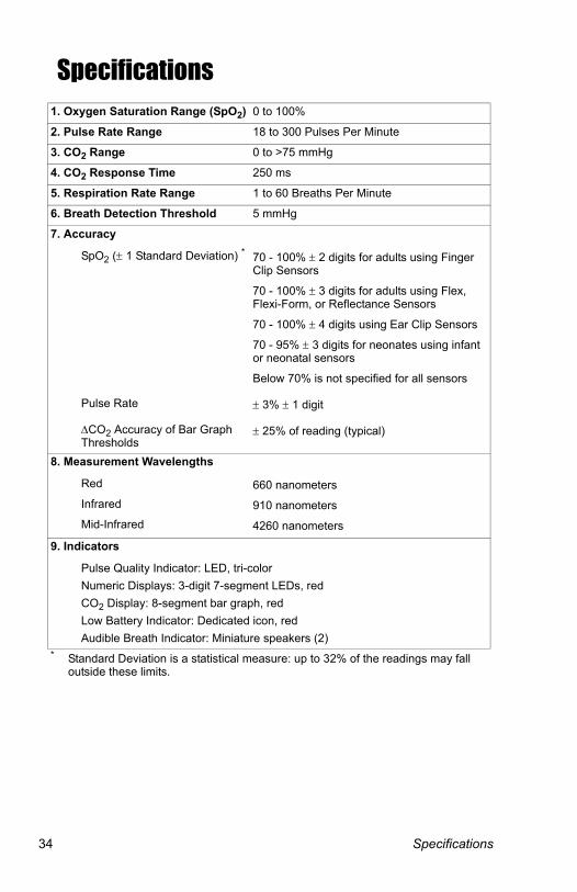
Specifications1. Oxygen Saturation Range (SpO2) 0 to 100%
2. Pulse Rate Range 18 to 300 Pulses Per Minute
3. CO2 Range 0 to >75 mmHg
4. CO2 Response Time 250 ms
5. Respiration Rate Range 1 to 60 Breaths Per Minute
6. Breath Detection Threshold 5 mmHg
7. Accuracy
SpO2 (± 1 Standard Deviation) * 70 - 100% ± 2 digits for adults using Finger Clip Sensors
70 - 100% ± 3 digits for adults using Flex, Flexi-Form, or Reflectance Sensors
70 - 100% ± 4 digits using Ear Clip Sensors
70 - 95% ± 3 digits for neonates using infant or neonatal sensors
Below 70% is not specified for all sensors
Pulse Rate ± 3% ± 1 digit
ΔCO2 Accuracy of Bar Graph Thresholds
± 25% of reading (typical)
8. Measurement Wavelengths
Red 660 nanometersInfrared 910 nanometersMid-Infrared 4260 nanometers
9. Indicators
Pulse Quality Indicator: LED, tri-colorNumeric Displays: 3-digit 7-segment LEDs, redCO2 Display: 8-segment bar graph, redLow Battery Indicator: Dedicated icon, redAudible Breath Indicator: Miniature speakers (2)
* Standard Deviation is a statistical measure: up to 32% of the readings may fall outside these limits.
4 Specifications
S
1
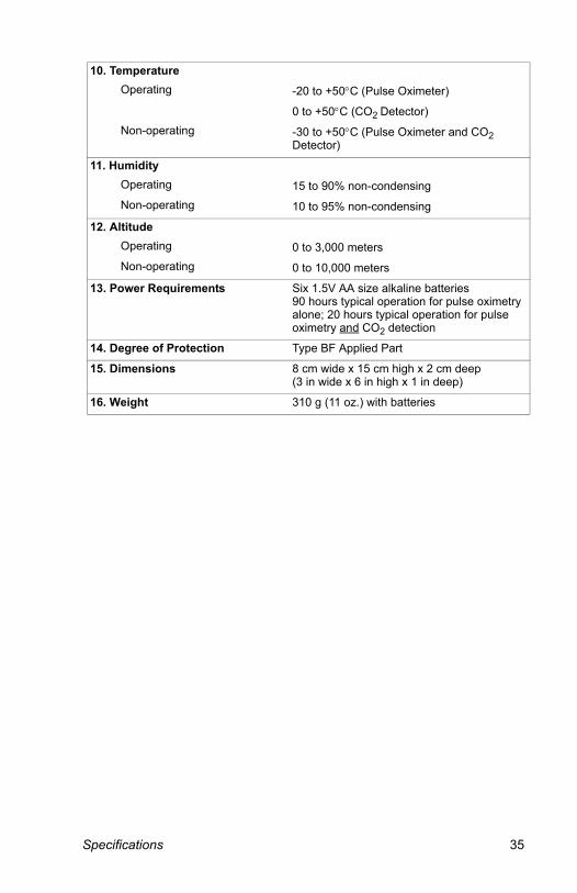
10. TemperatureOperating -20 to +50°C (Pulse Oximeter)
0 to +50°C (CO2 Detector)Non-operating -30 to +50°C (Pulse Oximeter and CO2
Detector)
11. HumidityOperating 15 to 90% non-condensingNon-operating 10 to 95% non-condensing
12. AltitudeOperating 0 to 3,000 metersNon-operating 0 to 10,000 meters
13. Power Requirements Six 1.5V AA size alkaline batteries 90 hours typical operation for pulse oximetry alone; 20 hours typical operation for pulse oximetry and CO2 detection
14. Degree of Protection Type BF Applied Part
15. Dimensions 8 cm wide x 15 cm high x 2 cm deep (3 in wide x 6 in high x 1 in deep)
16. Weight 310 g (11 oz.) with batteries
pecifications 35
3
1
ServiceCAUTION! Model 9843 Pulse Oximeter and Carbon Dioxide
Detectors are sensitive electronic instruments and must be repaired by knowledgeable and specially trained personnel only.
Any sign or evidence of opening the system, field service by non-NONIN personnel, tampering, or any kind of misuse or abuse of the system, shall void the warranty in its entirety.The solid state circuitry within the Model 9843 requires no periodic maintenance or calibration.
NONIN does not recommend field repair of the Model 9843. The circuit board in the Model 9843 is a multi-layer board using very narrow traces. Due to the very small trace size, extreme care must be used when replacing components to prevent permanent non-repairable damage to the circuit board. Most components are surface-mounted and require special hot air jet soldering and desoldering equipment. After any repairs are made, the Model 9843 must be tested to ensure correct operation.
All repair work on the Model 9843 should be done by trained NONIN personnel. For additional technical information contact NONIN’s Customer Support department at:
Nonin Medical, Inc.13700 1st Avenue North
Plymouth, Minnesota 55441-5443 USA
(763) 553-9968(800) 356-8874 (USA and Canada)
FAX: (763) 553-7807
All non-warranty work shall be done according to NONIN standard rates and charges in effect at the time of delivery to NONIN. All repairs include an 18-hour minimum burn-in and a complete retest of the Model 9843 using factory test fixtures.
6 Service

W
1
WarrantyNONIN MEDICAL, INCORPORATED, (NONIN) warrants to the purchaser, for a period of three years from the date of delivery, each system exclusive of sensors, cables, airway adapter tubes, and batteries. (Refer to the individual package inserts for specific warranty information for sensors, cables, and accessories.) NONIN shall repair all systems found to be defective in accordance with this warranty, free of charge, for which NONIN has been notified by the purchaser by serial number that there is a defect, provided said notification occurs within the applicable warranty period. This warranty shall be the sole and exclusive remedy by the purchaser hereunder for any systems delivered to the purchaser which are found to be defective in any manner whether such remedies be in contract, tort or by law.
This warranty excludes cost of delivery to and from NONIN. All repaired units shall be received by the purchaser at NONIN's place of business. For any system sent to NONIN for warranty repair which is found to be within specification, the purchaser agrees to pay $100.00 (US dollars).
These systems are sensitive and must be repaired by knowledgeable and specially trained personnel only. Accordingly, any sign or evidence of opening the system, field service by non-NONIN personnel, tampering, or any kind of misuse or abuse of the system, shall void the warranty in its entirety.
All non-warranty work shall be done according to NONIN standard rates and charges in effect at the time of delivery to NONIN.
DISCLAIMER/EXCLUSIVITY OF WARRANTY
THE EXPRESS WARRANTIES SET FORTH IN THIS MANUAL ARE EXCLUSIVE AND NO OTHER WARRANTIES OF ANY KIND, WHETHER STATUTORY, WRITTEN, ORAL, OR IMPLIED INCLUDING WARRANTIES OF FITNESS FOR A PARTICULAR PURPOSE OR MERCHANTABILITY SHALL APPLY.
arranty 37

3
1
AccessoriesThe following NONIN accessories function with the Model 9843:
For more information about NONIN parts and accessories contact your distributor, or contact NONIN at (800) 356-8874 (USA and Canada) or (763) 553-9968.
Carbon Dioxide Sensor Assembly9840AAT Airway Adapter Tube, 12 per box9840SA Carbon Dioxide Sensor
Pulse Oximeter Reusable Sensors8000AA-1 Adult Articulated Finger Clip Sensor (1 meter)8000AA-3 Adult Articulated Finger Clip Sensor (3 meter)8000AP Pediatric Finger Clip Sensor8000J Adult Flex Sensor8008J Infant Flex Sensor8001J Neonatal Flex Sensor8000Q Ear Clip Sensor8000R Reflectance Sensor
Pulse Oximeter Disposable Sensors7000A Adult Finger Flexi-Form® II Sensor, 10 per box7000P Pediatric Finger Flexi-Form® II Sensor, 10 per box7000I Infant Toe Flexi-Form® II Sensor, 10 per box7000N Neonatal Foot Flexi-Form® II Sensor, 10 per box7000D Flexi-Form Sensor Assortment Pack, 10 per box
Accessories8000H Reflectance Sensor Holder System8000S Patient Simulator8500I Patient Extension Cable (1 meter)9840CC Carrying Case8500MB Mounting Bracket (Wall or Pole Mount System)8500RB Rubber BumpernVISION® Data Management Software for Oximetry Screening1000MC Memory Cable (for use with nVISION software)
8 Accessories
T
Sy
Thenot
.
Theindillu
.
A dleftdis
d t
Thedistherate
Therateto tdismo
e e
s
to
Andispulduruseequ
d
1
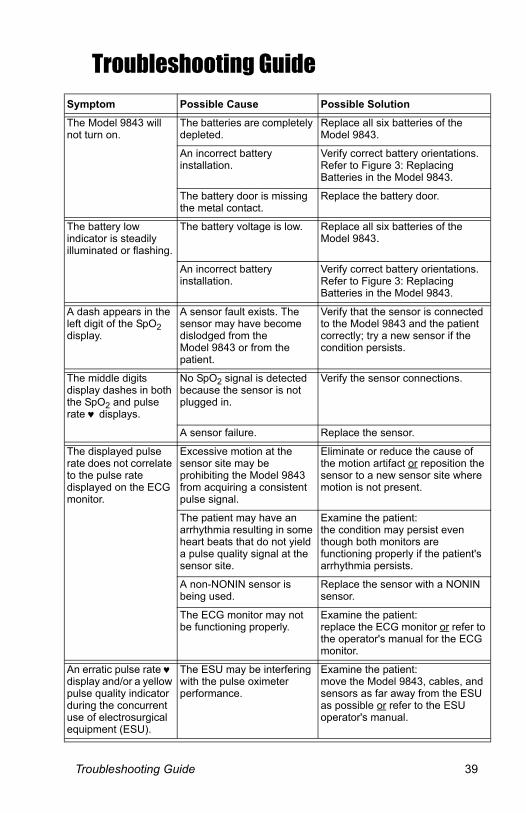
Troubleshooting Guide
mptom Possible Cause Possible Solution
Model 9843 will turn on.
The batteries are completely depleted.
Replace all six batteries of the Model 9843.
An incorrect battery installation.
Verify correct battery orientationsRefer to Figure 3: Replacing Batteries in the Model 9843.
The battery door is missing the metal contact.
Replace the battery door.
battery low icator is steadily minated or flashing.
The battery voltage is low. Replace all six batteries of the Model 9843.
An incorrect battery installation.
Verify correct battery orientationsRefer to Figure 3: Replacing Batteries in the Model 9843.
ash appears in the digit of the SpO2 play.
A sensor fault exists. The sensor may have become dislodged from the Model 9843 or from the patient.
Verify that the sensor is connecteto the Model 9843 and the patiencorrectly; try a new sensor if the condition persists.
middle digits play dashes in both SpO2 and pulse ♥ displays.
No SpO2 signal is detected because the sensor is not plugged in.
Verify the sensor connections.
A sensor failure. Replace the sensor.
displayed pulse does not correlate
he pulse rate played on the ECG nitor.
Excessive motion at the sensor site may be prohibiting the Model 9843 from acquiring a consistent pulse signal.
Eliminate or reduce the cause of the motion artifact or reposition thsensor to a new sensor site whermotion is not present.
The patient may have an arrhythmia resulting in some heart beats that do not yield a pulse quality signal at the sensor site.
Examine the patient: the condition may persist even though both monitors are functioning properly if the patient'arrhythmia persists.
A non-NONIN sensor is being used.
Replace the sensor with a NONINsensor.
The ECG monitor may not be functioning properly.
Examine the patient: replace the ECG monitor or refer the operator's manual for the ECGmonitor.
erratic pulse rate ♥ play and/or a yellow se quality indicator ing the concurrent of electrosurgical ipment (ESU).
The ESU may be interfering with the pulse oximeter performance.
Examine the patient: move the Model 9843, cables, ansensors as far away from the ESUas possible or refer to the ESU operator's manual.
roubleshooting Guide 39
4
Tinyp
Ugp
Tinreps
Sod
Tpcm
S
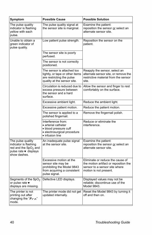
1
he pulse quality dicator is flashing
ellow with each ulse.
The pulse quality signal at the sensor site is marginal.
Examine the patient: reposition the sensor or select an alternate sensor site.
nable to obtain a reen indicator of ulse quality.
Low patient pulse strength. Reposition the sensor on the patient.
The sensor site is poorly perfused.
The sensor is not correctly positioned.
The sensor is attached too tightly, or tape or other items are restricting the pulse quality at the sensor site.
Reapply the sensor, select an alternate sensor site, or remove therestrictive material from the sensorsite.
Circulation is reduced due to excess pressure between the sensor and a hard surface.
Allow the sensor and finger to rest comfortably on the surface.
Excessive ambient light. Reduce the ambient light.
Excessive patient motion. Reduce the patient motion.
The sensor is applied to a polished fingernail.
Remove the fingernail polish.
Interference from: • arterial catheter • blood pressure cuff • electrosurgical procedure • infusion line
Reduce or eliminate the interference.
he pulse quality dicator is flashing d and the SpO2 and
ulse rate ♥ displays how dashes.
An inadequate pulse signal at the sensor site.
Examine the patient: reposition the sensor or select an alternate sensor site.
Excessive motion at the sensor site may be prohibiting the Model 9843 from acquiring a consistent pulse signal.
Eliminate or reduce the cause of the motion artifact or reposition thesensor to a sensor site where motion is not present.
egments of the SpO2 r pulse rate ♥ isplays are missing.
Defective LED displays. Displayed values may not be reliable; discontinue use of the Model 9843.
he printer is not rinting out after hanging the “Prn” ode.
The printer mode did not get updated internally.
Reset the Model 9843 by turning it off and then on.
ymptom Possible Cause Possible Solution
0 Troubleshooting Guide
T
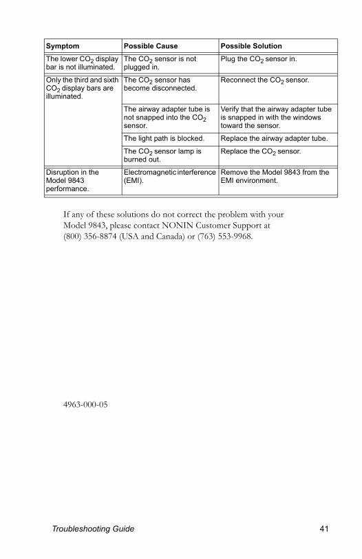
Thebar
OnCOillu
e
DisMoper
Sy
1
If any of these solutions do not correct the problem with your Model 9843, please contact NONIN Customer Support at (800) 356-8874 (USA and Canada) or (763) 553-9968.
4963-000-05
lower CO2 display is not illuminated.
The CO2 sensor is not plugged in.
Plug the CO2 sensor in.
ly the third and sixth 2 display bars are
minated.
The CO2 sensor has become disconnected.
Reconnect the CO2 sensor.
The airway adapter tube is not snapped into the CO2 sensor.
Verify that the airway adapter tubis snapped in with the windows toward the sensor.
The light path is blocked. Replace the airway adapter tube.
The CO2 sensor lamp is burned out.
Replace the CO2 sensor.
ruption in the del 9843 formance.
Electromagnetic interference (EMI).
Remove the Model 9843 from theEMI environment.
mptom Possible Cause Possible Solution
roubleshooting Guide 41