Embed Size (px)
Citation preview
GE Healthcare
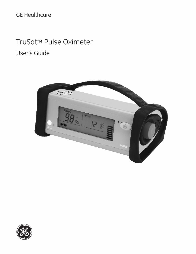
TruSat™ Pulse OximeterUser’s Guide


GE Healthcare
TruSat™ Pulse OximeterUser’s Guide
6050-0006-815March 2005

ImportantRx Only (USA)
Attention! Consult the accompanying instructions, including all safetyprecautions, before using this device.
Responsibility of the manufacturerThe safety, reliability, and performance of this device can be assured by themanufacturer only under the following conditions:
• Assembly, extensions, readjustments, modifications, and repairs are carried out byauthorized personnel.
• The electrical installation complies with relevant standards and regulations.
• The device is used in accordance with this manual and is serviced and maintained inaccordance with the TruSat Technical Reference Manual.
Service and repairService and repair procedures must be performed by authorized service personnel.Repair this device or its parts only in accordance with instructions provided by themanufacturer. To order replacement parts or for assistance, contact an authorizedservice office. When shipping the monitor for repair, clean the monitor, allow it to drycompletely, and pack it for shipment in the original shipping container, if possible.
TrademarksDatex®, Ohmeda®, TruSat™ and other trademarks (ComWheel™, OxyTip®, PIr®,TruSignal™, TruTrak®) are the property of GE Healthcare Finland Oy. All other productand company names are the property of their respective owners.
0537
GE Healthcare Finland OyHelsinki, Finland+358 10 394 11www.gehealthcare.com
© 2005 General Electric Company. All rights reserved.
Contents
i
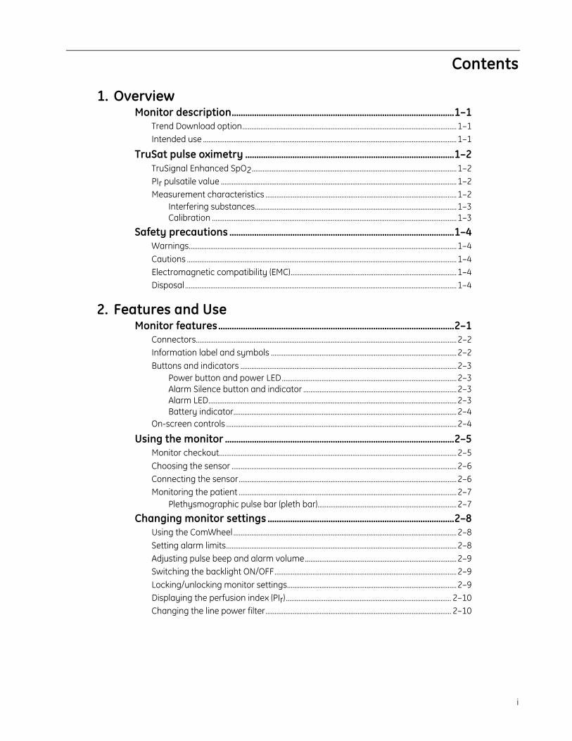
1. OverviewMonitor description...................................................................................................1–1
Trend Download option.......................................................................................................................1–1Intended use .............................................................................................................................................1–1
TruSat pulse oximetry .............................................................................................1–2TruSignal Enhanced SpO2..................................................................................................................1–2PIr pulsatile value ...................................................................................................................................1–2Measurement characteristics ..........................................................................................................1–2
Interfering substances................................................................................................................1–3Calibration ........................................................................................................................................1–3
Safety precautions ....................................................................................................1–4Warnings.....................................................................................................................................................1–4Cautions ......................................................................................................................................................1–4Electromagnetic compatibility (EMC)............................................................................................1–4Disposal .......................................................................................................................................................1–4
2. Features and UseMonitor features.........................................................................................................2–1
Connectors.................................................................................................................................................2–2Information label and symbols .......................................................................................................2–2Buttons and indicators ........................................................................................................................2–3
Power button and power LED.................................................................................................2–3Alarm Silence button and indicator .....................................................................................2–3Alarm LED..........................................................................................................................................2–3Battery indicator............................................................................................................................2–4
On-screen controls ................................................................................................................................2–4
Using the monitor ......................................................................................................2–5Monitor checkout....................................................................................................................................2–5Choosing the sensor .............................................................................................................................2–6Connecting the sensor.........................................................................................................................2–6Monitoring the patient .........................................................................................................................2–7
Plethysmographic pulse bar (pleth bar).............................................................................2–7
Changing monitor settings ...................................................................................2–8Using the ComWheel ............................................................................................................................2–8Setting alarm limits................................................................................................................................2–8Adjusting pulse beep and alarm volume....................................................................................2–9Switching the backlight ON/OFF.....................................................................................................2–9Locking/unlocking monitor settings..............................................................................................2–9Displaying the perfusion index (PIr) ............................................................................................ 2–10Changing the line power filter....................................................................................................... 2–10
Contents
ii
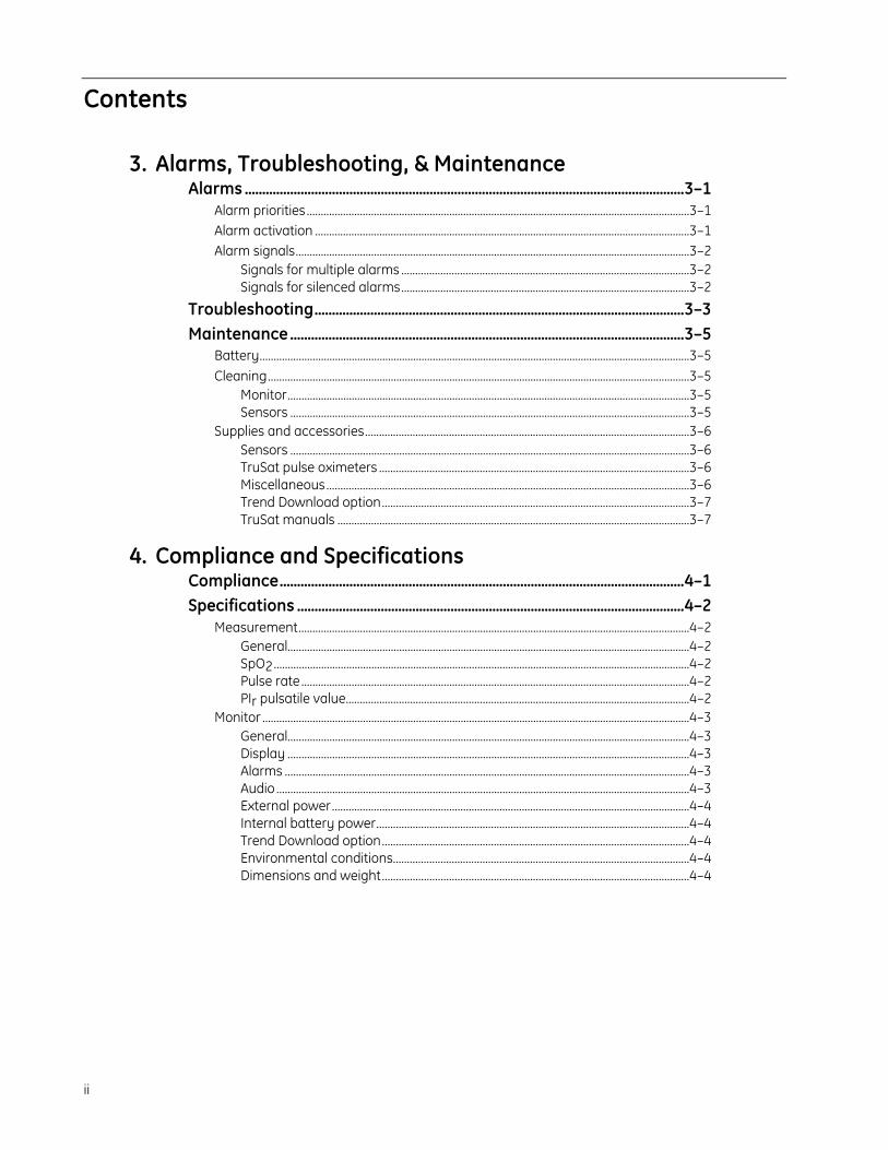
3. Alarms, Troubleshooting, & MaintenanceAlarms ..............................................................................................................................3–1
Alarm priorities .........................................................................................................................................3–1Alarm activation ......................................................................................................................................3–1Alarm signals.............................................................................................................................................3–2
Signals for multiple alarms .......................................................................................................3–2Signals for silenced alarms.......................................................................................................3–2
Troubleshooting..........................................................................................................3–3Maintenance.................................................................................................................3–5
Battery..........................................................................................................................................................3–5Cleaning.......................................................................................................................................................3–5
Monitor................................................................................................................................................3–5Sensors ...............................................................................................................................................3–5
Supplies and accessories....................................................................................................................3–6Sensors ...............................................................................................................................................3–6TruSat pulse oximeters ...............................................................................................................3–6Miscellaneous..................................................................................................................................3–6Trend Download option..............................................................................................................3–7TruSat manuals ..............................................................................................................................3–7
4. Compliance and SpecificationsCompliance....................................................................................................................4–1Specifications ...............................................................................................................4–2
Measurement............................................................................................................................................4–2General................................................................................................................................................4–2SpO2.....................................................................................................................................................4–2Pulse rate...........................................................................................................................................4–2PIr pulsatile value...........................................................................................................................4–2
Monitor .........................................................................................................................................................4–3General................................................................................................................................................4–3Display ................................................................................................................................................4–3Alarms .................................................................................................................................................4–3Audio ....................................................................................................................................................4–3External power................................................................................................................................4–4Internal battery power................................................................................................................4–4Trend Download option..............................................................................................................4–4Environmental conditions..........................................................................................................4–4Dimensions and weight..............................................................................................................4–4
Contents
iii
A. Trend Download OptionTrend data collection .............................................................................................. A–1
Patient identification number...........................................................................................................A–1
Alarm annunciation capability .......................................................................... A–2Setting the clock ........................................................................................................ A–2Printing to the portable printer ......................................................................... A–3
Connecting the printer.........................................................................................................................A–3Printing summary statistics for one or more patients.........................................................A–4
Sample printout: Summary statistics ................................................................................A–4Printing real-time data.........................................................................................................................A–5
Sample printout: Real-time data..........................................................................................A–5
Trend Download PC software ............................................................................. A–6PC requirements......................................................................................................................................A–6Software installation.............................................................................................................................A–6Setup.............................................................................................................................................................A–7Starting the Trend Download program .......................................................................................A–7
Trend Download program options .......................................................................................A–7
B. WarrantyWarranty ........................................................................................................................B-1

1–1
1. OVERVIEWThis chapter contains:
• A preview of the pulse oximetry features and measurement.
• General safety precautions to consider when using the monitor.
• A brief description of the monitor.
Monitor descriptionThe TruSat™ pulse oximeter is a durable, reliable, and portable monitor. It featuresTruSignal™ Enhanced SpO2 and PIr®, a relative perfusion index. The monitor is poweredby an internal battery, which is charged through an external power supply.
Important: When using the monitor for the first time or after removing it fromextended storage, charge the battery for three hours BEFORE you power ON.
The monitor contains an easy-to-read display with a backlight for low-light conditions.Information that appears on the display includes the following:
• SpO2, pulse rate, and PIr measurements.
• All alarm limit settings.
• Indicators for plethysmographic pulse, battery capacity, and silenced alarms.
The monitor also contains on-screen controls for changing monitor settings, such asalarm limits, volume, and the backlight. A lock function, when activated, protects againstunintended changes to settings.
The alarm system generates audible and visual signals that vary according to thepriority of the alarm.
Trend Download optionThe Trend Download option allows you to set the monitor clock, print, and downloadtrends to a computer. Monitors can be factory-configured with this option. An upgradekit is also available.
NOTE: If your monitor is configured with the Trend Download option, be sure to set themonitor clock before monitoring patients.
Intended useThe TruSat pulse oximeter is indicated for spot-checking and continuous monitoring offunctional oxygen saturation and pulse rate, including monitoring during conditions ofclinical patient motion1 or low perfusion. This device is intended for use with adult,pediatric, and neonatal patients in both hospital and non-hospital environments.
Important: Only OxyTip®+ sensors can be used with this monitor.
1 Anesthesia & Analgesia. 2002;94,1S, S54-S60
TruSat User’s Guide
1–2
TruSat pulse oximetryTruSignal Enhanced SpO2
TruSignal Enhanced SpO2 offers improved performance, especially during challengingconditions of clinical motion and low perfusion. With ultra-low-noise technology,TruSignal selects the appropriate clinically-developed algorithm to compensate forweak or motion-induced signals and generate reliable saturation readings.
PIr pulsatile valueThe perfusion index measurement—the PIr pulsatile value—is a quick and easy-to-useclinical tool that provides a dynamic numeric reflection of perfusion at the sensor site.PIr is a relative value that varies from patient to patient.
The PIr pulsatile value indicates the strength of the pulse signal at the sensor site—thehigher the PIr value, the stronger the pulse signal. A strong pulse signal increases thevalidity of SpO2 and pulse rate data. Clinicians can use the PIr value to compare thestrength of the pulse signal at different sites on a patient in order to locate the best sitefor the sensor—the site with the strongest pulse signal.
Measurement characteristicsThe pulse oximetry measurement uses a two-wavelength pulsatile system—red andinfrared light—to distinguish between oxyhemoglobin (O2Hb) and reduced hemoglobin(HHb). The light is emitted from the oximeter sensor, which contains the light source anda photodetector.
• The light source consists of red and infrared light-emitting diodes (LEDs).
• The photodetector is an electronic device that produces an electrical currentproportional to incident light intensity.
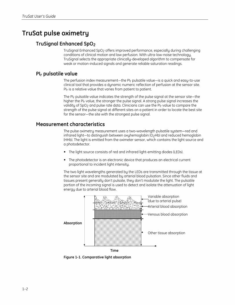
The two light wavelengths generated by the LEDs are transmitted through the tissue atthe sensor site and are modulated by arterial blood pulsation. Since other fluids andtissues present generally don’t pulsate, they don’t modulate the light. The pulsatileportion of the incoming signal is used to detect and isolate the attenuation of lightenergy due to arterial blood flow.
Absorption
Time
Figure 1-1. Comparative light absorption
Variable absorption(due to arterial pulse)
Arterial blood absorption
Venous blood absorption
Other tissue absorption
Overview
1–3
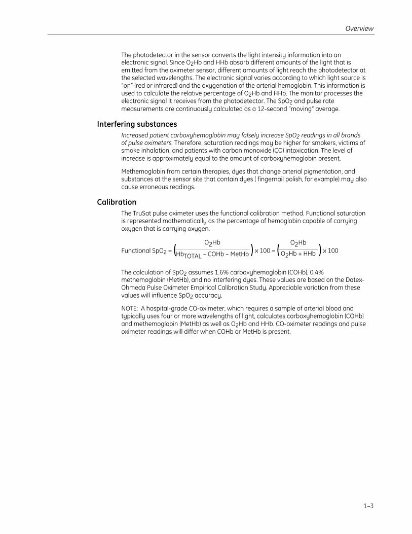
The photodetector in the sensor converts the light intensity information into anelectronic signal. Since O2Hb and HHb absorb different amounts of the light that isemitted from the oximeter sensor, different amounts of light reach the photodetector atthe selected wavelengths. The electronic signal varies according to which light source is“on” (red or infrared) and the oxygenation of the arterial hemoglobin. This information isused to calculate the relative percentage of O2Hb and HHb. The monitor processes theelectronic signal it receives from the photodetector. The SpO2 and pulse ratemeasurements are continuously calculated as a 12-second “moving” average.
Interfering substancesIncreased patient carboxyhemoglobin may falsely increase SpO2 readings in all brandsof pulse oximeters. Therefore, saturation readings may be higher for smokers, victims ofsmoke inhalation, and patients with carbon monoxide (CO) intoxication. The level ofincrease is approximately equal to the amount of carboxyhemoglobin present.
Methemoglobin from certain therapies, dyes that change arterial pigmentation, andsubstances at the sensor site that contain dyes ( fingernail polish, for example) may alsocause erroneous readings.
CalibrationThe TruSat pulse oximeter uses the functional calibration method. Functional saturationis represented mathematically as the percentage of hemoglobin capable of carryingoxygen that is carrying oxygen.
Functional SpO2 = ( ) x 100 = ( ) x 100
The calculation of SpO2 assumes 1.6% carboxyhemoglobin (COHb), 0.4%methemoglobin (MetHb), and no interfering dyes. These values are based on the Datex-Ohmeda Pulse Oximeter Empirical Calibration Study. Appreciable variation from thesevalues will influence SpO2 accuracy.
NOTE: A hospital-grade CO-oximeter, which requires a sample of arterial blood andtypically uses four or more wavelengths of light, calculates carboxyhemoglobin (COHb)and methemoglobin (MetHb) as well as O2Hb and HHb. CO-oximeter readings and pulseoximeter readings will differ when COHb or MetHb is present.
O2Hb
O2Hb + HHb
O2Hb
HbTOTAL – COHb – MetHb

TruSat User’s Guide
1–4
Safety precautionsPrecautions associated with following safe practices while using the monitor appearthroughout this manual. General precautions are listed below. Carefully read allprecautions in this manual before using the monitor.
NOTE: For complete information about the safe and appropriate use of a sensor,consult the instructions for that sensor.
WarningsWARNINGS indicate potentially harmful situations that may cause injury toa patient or operator.
• It is possible for any device to malfunction. Always verify unusual data byperforming a formal patient assessment.
• Do not use the monitor in the presence of any flammable anesthetic mixture.
• Use only hospital-grade, grounded power outlets.
• Use only sensors and cables specified for use with this monitor. Failure to do so maycause interference with the measurement or result in increased emissions,decreased immunity, or damage to the equipment or system.
• This monitor does not measure respiration and should never be used as a substitutefor an apnea monitor.
• This monitor is not intended for use in a magnetic resonance imaging (MRI)environment.
CautionsCAUTIONS indicate conditions that may lead to equipment damage ormalfunction.
• Do not store or use the monitor outside the temperature and humidity ranges statedin the Specifications section of this manual.
Electromagnetic compatibility (EMC)Electromagnetic interference, including interference from portable and mobile radiofrequency (RF) communications equipment, can affect this monitor.
When using this monitor, take precautions to ensure electromagnetic compatibility. Formore information, refer to the Technical Reference Manual.
DisposalRecycle or dispose of this medical device, its components, and its packing materials inaccordance with local environmental and waste disposal regulations.

2–1
2. FEATURES AND USEThis chapter contains:
• Descriptions of the monitor’s features and controls.
• Instructions for using the monitor.
• Instructions for changing monitor settings.
Monitor featuresNOTE: The monitor is shown without the handle.
Figure 2-1. Monitor features
1 Oxygen saturation (SpO2) measurement value
2 SpO2 high and low alarm limit settings, adjustable
3 Pulse rate measurement value
4 Pulse rate high and low alarm limit settings, adjustable
5 Plethysmographic pulse bar (pleth bar)
6 Alarm LED
7 Alarm Silence button
8 ComWheel navigation and selection knob for changing monitor settings
9 Display area for on-screen control symbols
10 Battery indicator
11 Power button and external power LED
TruSat User’s Guide
2–2
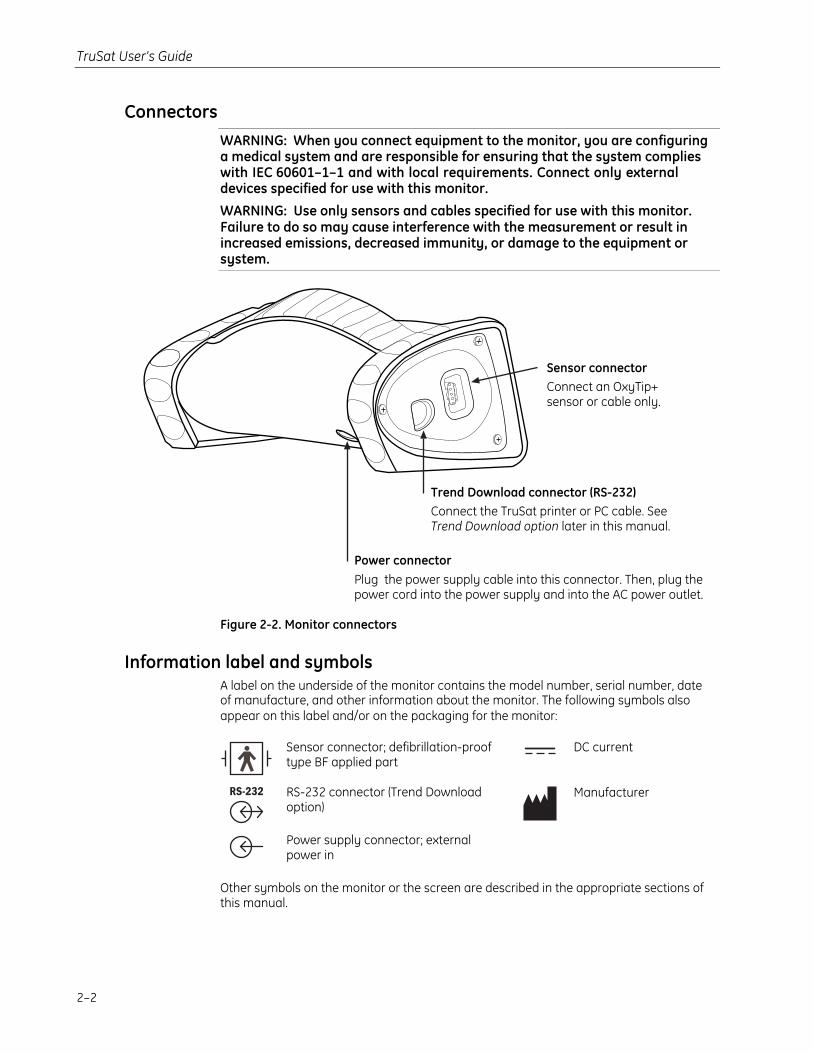
ConnectorsWARNING: When you connect equipment to the monitor, you are configuringa medical system and are responsible for ensuring that the system complieswith IEC 60601–1–1 and with local requirements. Connect only externaldevices specified for use with this monitor.
WARNING: Use only sensors and cables specified for use with this monitor.Failure to do so may cause interference with the measurement or result inincreased emissions, decreased immunity, or damage to the equipment orsystem.
Figure 2-2. Monitor connectors
Information label and symbolsA label on the underside of the monitor contains the model number, serial number, dateof manufacture, and other information about the monitor. The following symbols alsoappear on this label and/or on the packaging for the monitor:
Sensor connector; defibrillation-prooftype BF applied part
DC current
RS-232 connector (Trend Downloadoption)
Manufacturer
Power supply connector; externalpower in
Other symbols on the monitor or the screen are described in the appropriate sections ofthis manual.
Sensor connectorConnect an OxyTip+sensor or cable only.
Trend Download connector (RS-232)Connect the TruSat printer or PC cable. SeeTrend Download option later in this manual.
Power connectorPlug the power supply cable into this connector. Then, plug thepower cord into the power supply and into the AC power outlet.
Features and Use
2–3
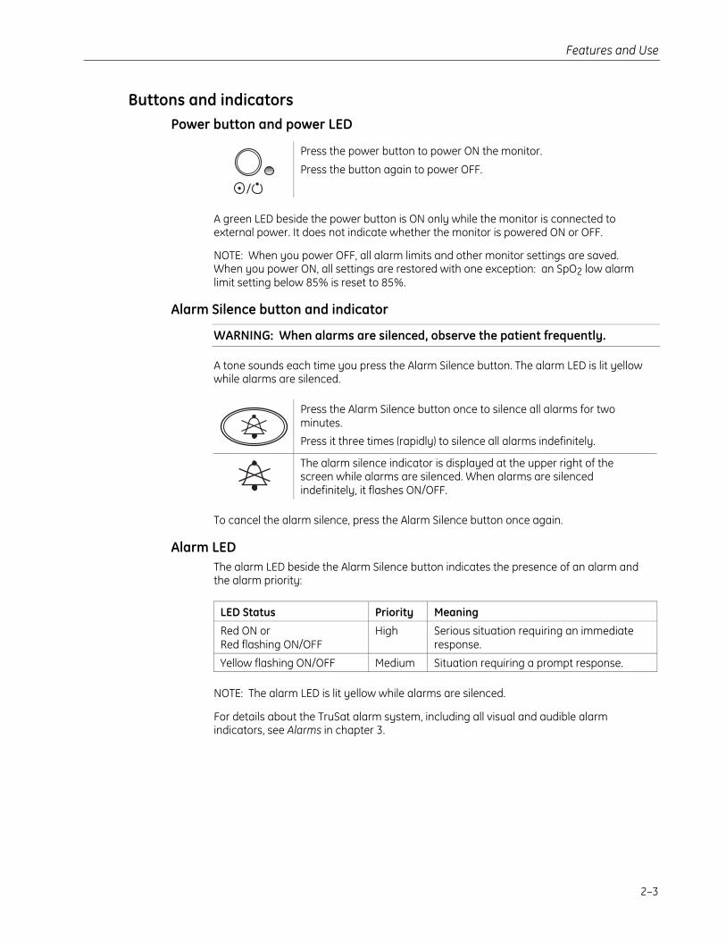
Buttons and indicatorsPower button and power LED
Press the power button to power ON the monitor.
Press the button again to power OFF.
A green LED beside the power button is ON only while the monitor is connected toexternal power. It does not indicate whether the monitor is powered ON or OFF.
NOTE: When you power OFF, all alarm limits and other monitor settings are saved.When you power ON, all settings are restored with one exception: an SpO2 low alarmlimit setting below 85% is reset to 85%.
Alarm Silence button and indicator
WARNING: When alarms are silenced, observe the patient frequently.
A tone sounds each time you press the Alarm Silence button. The alarm LED is lit yellowwhile alarms are silenced.
Press the Alarm Silence button once to silence all alarms for twominutes.
Press it three times (rapidly) to silence all alarms indefinitely.
The alarm silence indicator is displayed at the upper right of thescreen while alarms are silenced. When alarms are silencedindefinitely, it flashes ON/OFF.
To cancel the alarm silence, press the Alarm Silence button once again.
Alarm LEDThe alarm LED beside the Alarm Silence button indicates the presence of an alarm andthe alarm priority:
LED Status Priority Meaning
Red ON orRed flashing ON/OFF
High Serious situation requiring an immediateresponse.
Yellow flashing ON/OFF Medium Situation requiring a prompt response.
NOTE: The alarm LED is lit yellow while alarms are silenced.
For details about the TruSat alarm system, including all visual and audible alarmindicators, see Alarms in chapter 3.
TruSat User’s Guide
2–4
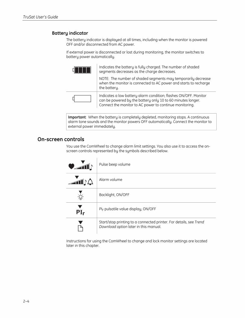
Battery indicatorThe battery indicator is displayed at all times, including when the monitor is poweredOFF and/or disconnected from AC power.
If external power is disconnected or lost during monitoring, the monitor switches tobattery power automatically.
Indicates the battery is fully charged. The number of shadedsegments decreases as the charge decreases.
NOTE: The number of shaded segments may temporarily decreasewhen the monitor is connected to AC power and starts to rechargethe battery.
Indicates a low battery alarm condition; flashes ON/OFF. Monitorcan be powered by the battery only 10 to 60 minutes longer.Connect the monitor to AC power to continue monitoring.
Important: When the battery is completely depleted, monitoring stops. A continuousalarm tone sounds and the monitor powers OFF automatically. Connect the monitor toexternal power immediately.
On-screen controlsYou use the ComWheel to change alarm limit settings. You also use it to access the on-screen controls represented by the symbols described below.
Pulse beep volume
Alarm volume
Backlight, ON/OFF
PIr pulsatile value display, ON/OFF
Start/stop printing to a connected printer. For details, see TrendDownload option later in this manual.
Instructions for using the ComWheel to change and lock monitor settings are locatedlater in this chapter.
Features and Use
2–5
Using the monitorMonitor checkout
Always check the operation of the monitor before using it to monitor a patient.
WARNING: Do not use the monitor if the startup tones do not sound, thevalidity of data is questionable, or if the monitor fails to function asdescribed. Refer to the appropriate sections of this manual to identify andcorrect the malfunction.
1. Plug the power supply cable into the power connector on the monitor. Then, connectthe power supply to the power outlet.
Important: When using the monitor for the first time or after removing it fromextended storage, charge the battery for three hours BEFORE you power ON.
2. Press the power button to power ON. Verify the following during startup:
• The power-on tones sound.
• All display elements, including on-screen symbols, illuminate briefly.
• The alarm LED is lit red, then yellow.
• The backlight is ON until dashes are displayed for the SpO2 and pulse rate. Thebacklight remains ON if it is set to ON.
• (Trend Download option only) A patient number (P01, P02, etc.) is displayed.
3. Power OFF and check the line power filter setting shown in the high pulse rate alarmarea: 50 (Hz) or 60 (Hz). If the setting matches your local line power frequency, go tothe next step. If it is different, go to Changing the line power filter later in this chapter.
4. Choose a sensor designed for use on a finger, place it on your finger, and connect itto the monitor. Power ON the monitor.
NOTE: All pleth bar segments pulsate until the measured values are displayed.
5. When the SpO2 and pulse rate values are displayed, verify that the lowest pleth barsegment remains visible while one or more of the other segments pulsate.
6. Remove the sensor from your finger. Verify that the alarm LED flashes red, an alarmtone sounds, and dashes replace the SpO2 and pulse rate values.
7. Place the sensor on your finger again. After the SpO2 and pulse rate values aredisplayed, unplug the sensor from the monitor. Verify that the alarm LED flashes red,an alarm tone sounds, and dashes replace the values.
8. Check the battery indicator. If the battery is low, recharge the battery before usingthe monitor.
Important: If the startup tones do not sound or if the monitor fails to function asdescribed, DO NOT use the monitor until the malfunction has been corrected. Refer toTroubleshooting later in this manual.
TruSat User’s Guide
2–6
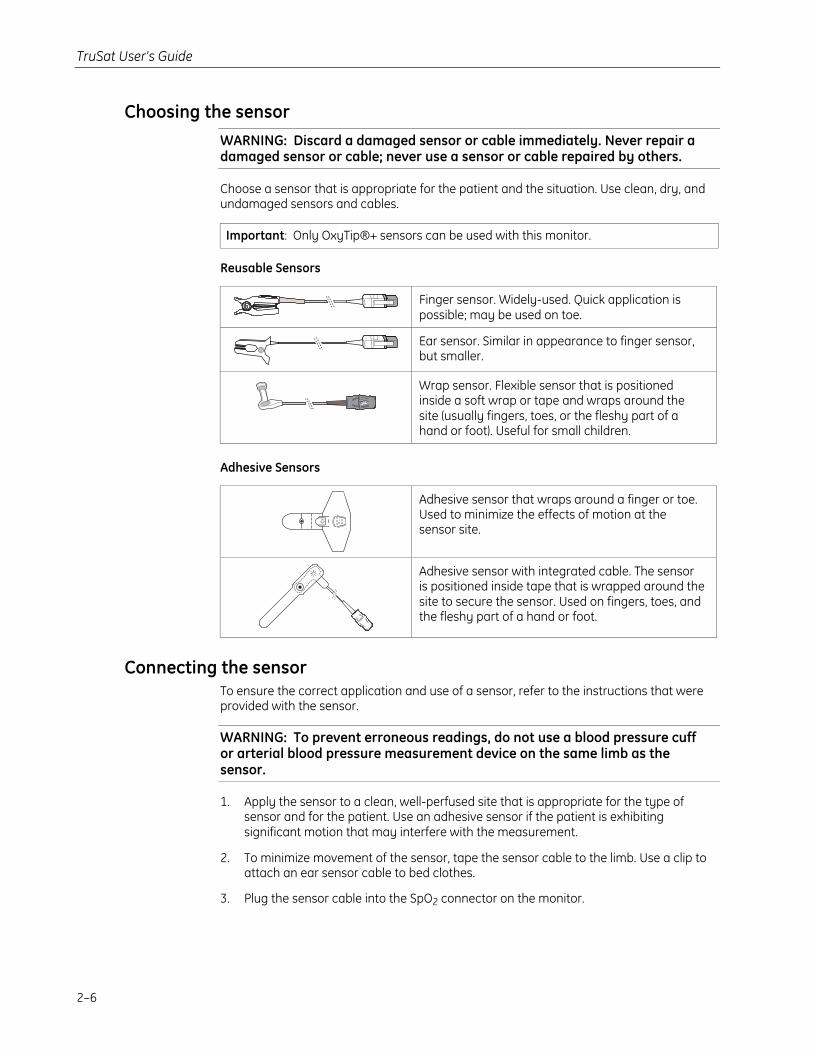
Choosing the sensorWARNING: Discard a damaged sensor or cable immediately. Never repair adamaged sensor or cable; never use a sensor or cable repaired by others.
Choose a sensor that is appropriate for the patient and the situation. Use clean, dry, andundamaged sensors and cables.
Important: Only OxyTip®+ sensors can be used with this monitor.
Reusable Sensors
Finger sensor. Widely-used. Quick application ispossible; may be used on toe.
Ear sensor. Similar in appearance to finger sensor,but smaller.
Wrap sensor. Flexible sensor that is positionedinside a soft wrap or tape and wraps around thesite (usually fingers, toes, or the fleshy part of ahand or foot). Useful for small children.
Adhesive Sensors
Adhesive sensor that wraps around a finger or toe.Used to minimize the effects of motion at thesensor site.
Adhesive sensor with integrated cable. The sensoris positioned inside tape that is wrapped around thesite to secure the sensor. Used on fingers, toes, andthe fleshy part of a hand or foot.
Connecting the sensorTo ensure the correct application and use of a sensor, refer to the instructions that wereprovided with the sensor.
WARNING: To prevent erroneous readings, do not use a blood pressure cuffor arterial blood pressure measurement device on the same limb as thesensor.
1. Apply the sensor to a clean, well-perfused site that is appropriate for the type ofsensor and for the patient. Use an adhesive sensor if the patient is exhibitingsignificant motion that may interfere with the measurement.
2. To minimize movement of the sensor, tape the sensor cable to the limb. Use a clip toattach an ear sensor cable to bed clothes.
3. Plug the sensor cable into the SpO2 connector on the monitor.
Features and Use
2–7
Monitoring the patientIf your monitor is configured with the Trend Download option, be sure to set the clockbefore you begin monitoring. For instructions, see Trend Download option later in thismanual.
WARNING: Conditions that may cause inaccurate readings and impactalarms include interfering substances, excessive ambient light, electricalinterference, excessive motion, low perfusion, low signal strength, incorrectsensor placement, poor sensor fit, and movement of the sensor on thepatient.
WARNING: Patient conditions (such as reddening, blistering, skindiscoloration, ischemic skin necrosis, and skin erosion) may warrantchanging the sensor site frequently or using a different style of sensor.
WARNING: The power supply may reach a temperature that can causepatient discomfort. Position the power supply so that it will not come intocontact with the patient.
Each time you monitor a patient:
• Verify that the signal strength is adequate and that the displayed values agree withyour clinical evaluation of the patient.
• Routinely check skin integrity and circulatory status at the sensor site.
• Adjust alarm limits according to the clinical condition of the patient.
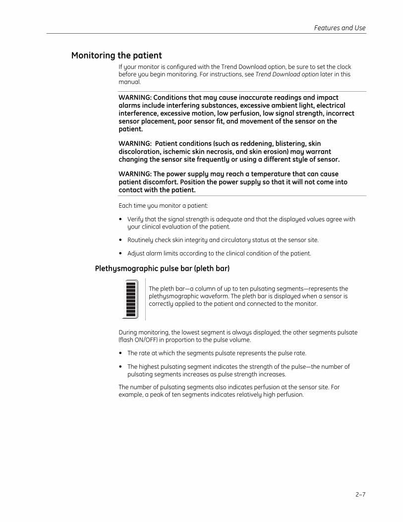
Plethysmographic pulse bar (pleth bar)
The pleth bar—a column of up to ten pulsating segments—represents theplethysmographic waveform. The pleth bar is displayed when a sensor iscorrectly applied to the patient and connected to the monitor.
During monitoring, the lowest segment is always displayed; the other segments pulsate(flash ON/OFF) in proportion to the pulse volume.
• The rate at which the segments pulsate represents the pulse rate.
• The highest pulsating segment indicates the strength of the pulse—the number ofpulsating segments increases as pulse strength increases.
The number of pulsating segments also indicates perfusion at the sensor site. Forexample, a peak of ten segments indicates relatively high perfusion.
TruSat User’s Guide
2–8
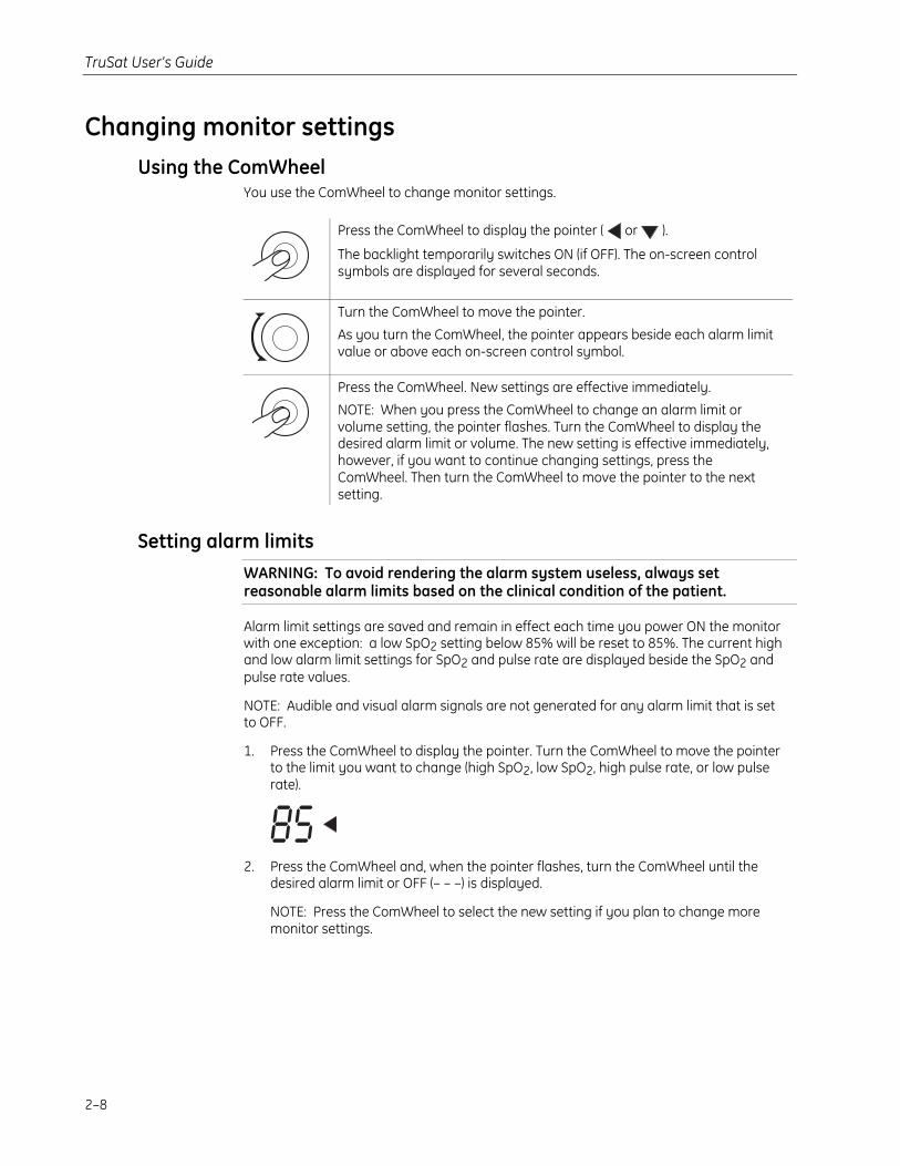
Changing monitor settingsUsing the ComWheel
You use the ComWheel to change monitor settings.
Press the ComWheel to display the pointer ( or ).
The backlight temporarily switches ON (if OFF). The on-screen controlsymbols are displayed for several seconds.
Turn the ComWheel to move the pointer.
As you turn the ComWheel, the pointer appears beside each alarm limitvalue or above each on-screen control symbol.
Press the ComWheel. New settings are effective immediately.
NOTE: When you press the ComWheel to change an alarm limit orvolume setting, the pointer flashes. Turn the ComWheel to display thedesired alarm limit or volume. The new setting is effective immediately,however, if you want to continue changing settings, press theComWheel. Then turn the ComWheel to move the pointer to the nextsetting.
Setting alarm limitsWARNING: To avoid rendering the alarm system useless, always setreasonable alarm limits based on the clinical condition of the patient.
Alarm limit settings are saved and remain in effect each time you power ON the monitorwith one exception: a low SpO2 setting below 85% will be reset to 85%. The current highand low alarm limit settings for SpO2 and pulse rate are displayed beside the SpO2 andpulse rate values.
NOTE: Audible and visual alarm signals are not generated for any alarm limit that is setto OFF.
1. Press the ComWheel to display the pointer. Turn the ComWheel to move the pointerto the limit you want to change (high SpO2, low SpO2, high pulse rate, or low pulserate).
2. Press the ComWheel and, when the pointer flashes, turn the ComWheel until thedesired alarm limit or OFF (– – –) is displayed.
NOTE: Press the ComWheel to select the new setting if you plan to change moremonitor settings.
Features and Use
2–9
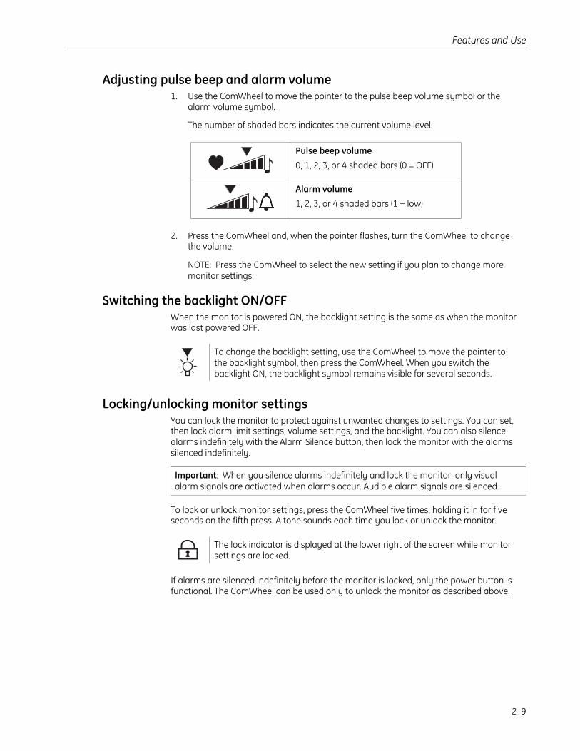
Adjusting pulse beep and alarm volume1. Use the ComWheel to move the pointer to the pulse beep volume symbol or the
alarm volume symbol.
The number of shaded bars indicates the current volume level.
Pulse beep volume
0, 1, 2, 3, or 4 shaded bars (0 = OFF)
Alarm volume
1, 2, 3, or 4 shaded bars (1 = low)
2. Press the ComWheel and, when the pointer flashes, turn the ComWheel to changethe volume.
NOTE: Press the ComWheel to select the new setting if you plan to change moremonitor settings.
Switching the backlight ON/OFFWhen the monitor is powered ON, the backlight setting is the same as when the monitorwas last powered OFF.
To change the backlight setting, use the ComWheel to move the pointer tothe backlight symbol, then press the ComWheel. When you switch thebacklight ON, the backlight symbol remains visible for several seconds.
Locking/unlocking monitor settingsYou can lock the monitor to protect against unwanted changes to settings. You can set,then lock alarm limit settings, volume settings, and the backlight. You can also silencealarms indefinitely with the Alarm Silence button, then lock the monitor with the alarmssilenced indefinitely.
Important: When you silence alarms indefinitely and lock the monitor, only visualalarm signals are activated when alarms occur. Audible alarm signals are silenced.
To lock or unlock monitor settings, press the ComWheel five times, holding it in for fiveseconds on the fifth press. A tone sounds each time you lock or unlock the monitor.
The lock indicator is displayed at the lower right of the screen while monitorsettings are locked.
If alarms are silenced indefinitely before the monitor is locked, only the power button isfunctional. The ComWheel can be used only to unlock the monitor as described above.
TruSat User’s Guide
2–10
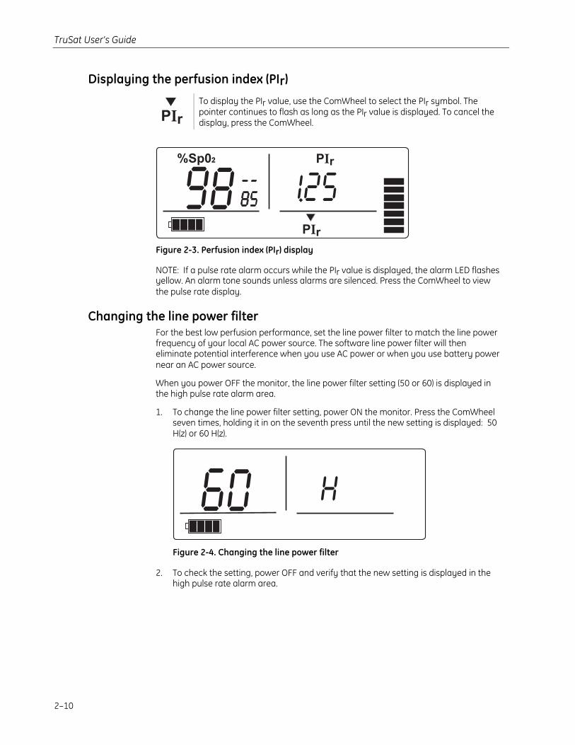
Displaying the perfusion index (PIr)
To display the PIr value, use the ComWheel to select the PIr symbol. Thepointer continues to flash as long as the PIr value is displayed. To cancel thedisplay, press the ComWheel.
Figure 2-3. Perfusion index (PIr) display
NOTE: If a pulse rate alarm occurs while the PIr value is displayed, the alarm LED flashesyellow. An alarm tone sounds unless alarms are silenced. Press the ComWheel to viewthe pulse rate display.
Changing the line power filterFor the best low perfusion performance, set the line power filter to match the line powerfrequency of your local AC power source. The software line power filter will theneliminate potential interference when you use AC power or when you use battery powernear an AC power source.
When you power OFF the monitor, the line power filter setting (50 or 60) is displayed inthe high pulse rate alarm area.
1. To change the line power filter setting, power ON the monitor. Press the ComWheelseven times, holding it in on the seventh press until the new setting is displayed: 50H(z) or 60 H(z).
Figure 2-4. Changing the line power filter
2. To check the setting, power OFF and verify that the new setting is displayed in thehigh pulse rate alarm area.
3–1
3. ALARMS, TROUBLESHOOTING, & MAINTENANCEThis chapter contains:
• Information about the alarm system.
• A chart for troubleshooting situations that may occur while using the monitor.
• Maintenance information, including a list of supplies and accessories that areapproved for use with the monitor.
AlarmsAlarms are visual or audible signals that alert you to a physiological or technical alarmcondition.
• Physiological alarm conditions occur when an SpO2 or pulse rate measurementmatches or exceeds the alarm limit setting.
• Technical alarm conditions occur when the monitor detects an equipment-relatedcondition, such as a depleted battery, a faulty sensor, or an internal malfunction.
Alarm prioritiesAlarms are prioritized according to the severity and urgency of the alarm condition. Thisallows you to identify and respond immediately to the highest priority alarms. The alarmpriorities are high and medium.
• High priority alarms indicate a serious situation that requires an immediate response.
• Medium priority alarms indicate a situation requiring a prompt response.
Alarm activationVisual alarm signals are activated when a measured value matches or exceeds its alarmlimit. The audible alarm signal is activated within ten seconds. However, the alarm tonesounds immediately when the SpO2 value is more than two digits beyond its alarm limitsetting, or when the pulse rate value is more than five digits beyond its alarm limitsetting.
TruSat User’s Guide
3–2
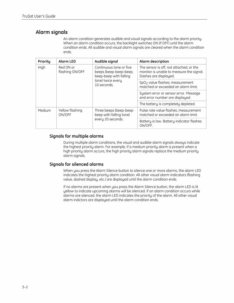
Alarm signalsAn alarm condition generates audible and visual signals according to the alarm priority.When an alarm condition occurs, the backlight switches ON (if OFF) until the alarmcondition ends. All audible and visual alarm signals are cleared when the alarm conditionends.
Priority Alarm LED Audible signal Alarm description
The sensor is off, not attached, or themonitor is unable to measure the signal.Dashes are displayed.
SpO2 value flashes; measurementmatched or exceeded an alarm limit.
System error or sensor error. Messageand error number are displayed.
High Red ON orflashing ON/OFF
Continuous tone or fivebeeps (beep-beep-beep,beep-beep with fallingtone) twice every10 seconds.
The battery is completely depleted.
Pulse rate value flashes; measurementmatched or exceeded an alarm limit.
Medium Yellow flashingON/OFF
Three beeps (beep-beep-beep with falling tone)every 20 seconds. Battery is low. Battery indicator flashes
ON/OFF.
Signals for multiple alarmsDuring multiple alarm conditions, the visual and audible alarm signals always indicatethe highest priority alarm. For example, if a medium priority alarm is present when ahigh priority alarm occurs, the high priority alarm signals replace the medium priorityalarm signals.
Signals for silenced alarmsWhen you press the Alarm Silence button to silence one or more alarms, the alarm LEDindicates the highest priority alarm condition. All other visual alarm indicators (flashingvalue, dashed display, etc.) are displayed until the alarm condition ends.
If no alarms are present when you press the Alarm Silence button, the alarm LED is lityellow to indicate upcoming alarms will be silenced. If an alarm condition occurs whilealarms are silenced, the alarm LED indicates the priority of the alarm. All other visualalarm indictors are displayed until the alarm condition ends.
Alarms, Troubleshooting, & Maintenance
3–3
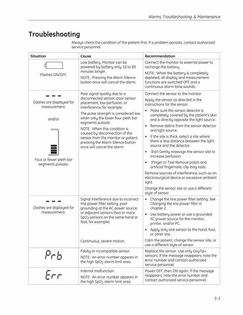
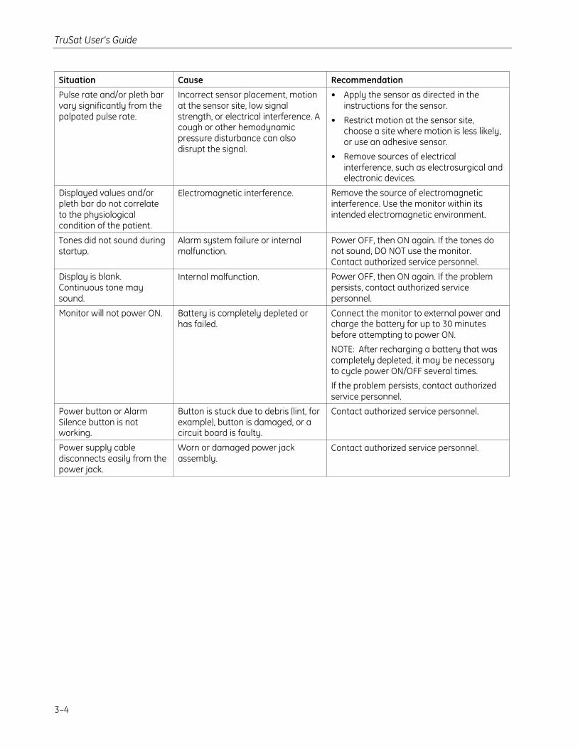
TroubleshootingAlways check the condition of the patient first. If a problem persists, contact authorizedservice personnel.
Situation Cause Recommendation
Flashes ON/OFF.
Low battery. Monitor can bepowered by battery only 10 to 60minutes longer.
NOTE: Pressing the Alarm Silencebutton once will cancel the alarm.
Connect the monitor to external power torecharge the battery.
NOTE: When the battery is completelydepleted, all display and measurementfunctions are switched OFF and acontinuous alarm tone sounds.
Dashes are displayed formeasurement.
and/or
Four or fewer pleth barsegments pulsate.
Poor signal quality due to adisconnected sensor, poor sensorplacement, low perfusion, orinterference, for example.
The pulse strength is considered lowwhen only the lower four pleth barsegments pulsate.
NOTE: When this condition iscaused by disconnection of thesensor from the monitor or patient,pressing the Alarm Silence buttononce will cancel the alarm.
Connect the sensor to the monitor.
Apply the sensor as directed in theinstructions for the sensor.
• Make sure the sensor detector iscompletely covered by the patient’s skinand is directly opposite the light source.
• Remove debris from the sensor detectorand light source.
• If the site is thick, select a site wherethere is less distance between the lightsource and the detector.
• (Ear) Gently massage the sensor site toincrease perfusion.
• (Finger or Toe) Remove polish andartificial fingernails; clip long nails.
Remove sources of interference, such as anelectrosurgical device or excessive ambientlight.
Change the sensor site or use a differentstyle of sensor.
Dashes are displayed formeasurement.
Signal interference due to incorrectline power filter setting, poorgrounding at the AC power source,or adjacent sensors (two or moreSpO2 sensors on the same hand orfoot, for example).
Continuous, severe motion.
• Change the line power filter setting. SeeChanging the line power filter inchapter 2.
• Use battery power or use a groundedAC power source for the monitor,printer, and/or PC.
• Apply only one sensor to the hand, foot,or other site.
Calm the patient, change the sensor site, oruse a different style of sensor.
Faulty or incompatible sensor.
NOTE: An error number appears inthe high SpO2 alarm limit area.
Replace the sensor. Use only OxyTip+sensors. If the message reappears, note theerror number and contact authorizedservice personnel.
Internal malfunction.
NOTE: An error number appears inthe high SpO2 alarm limit area.
Power OFF, then ON again. If the messagereappears, note the error number andcontact authorized service personnel.
TruSat User’s Guide
3–4
Situation Cause Recommendation
Pulse rate and/or pleth barvary significantly from thepalpated pulse rate.
Incorrect sensor placement, motionat the sensor site, low signalstrength, or electrical interference. Acough or other hemodynamicpressure disturbance can alsodisrupt the signal.
• Apply the sensor as directed in theinstructions for the sensor.
• Restrict motion at the sensor site,choose a site where motion is less likely,or use an adhesive sensor.
• Remove sources of electricalinterference, such as electrosurgical andelectronic devices.
Displayed values and/orpleth bar do not correlateto the physiologicalcondition of the patient.
Electromagnetic interference. Remove the source of electromagneticinterference. Use the monitor within itsintended electromagnetic environment.
Tones did not sound duringstartup.
Alarm system failure or internalmalfunction.
Power OFF, then ON again. If the tones donot sound, DO NOT use the monitor.Contact authorized service personnel.
Display is blank.Continuous tone maysound.
Internal malfunction. Power OFF, then ON again. If the problempersists, contact authorized servicepersonnel.
Monitor will not power ON. Battery is completely depleted orhas failed.
Connect the monitor to external power andcharge the battery for up to 30 minutesbefore attempting to power ON.
NOTE: After recharging a battery that wascompletely depleted, it may be necessaryto cycle power ON/OFF several times.
If the problem persists, contact authorizedservice personnel.
Power button or AlarmSilence button is notworking.
Button is stuck due to debris (lint, forexample), button is damaged, or acircuit board is faulty.
Contact authorized service personnel.
Power supply cabledisconnects easily from thepower jack.
Worn or damaged power jackassembly.
Contact authorized service personnel.
Alarms, Troubleshooting, & Maintenance
3–5
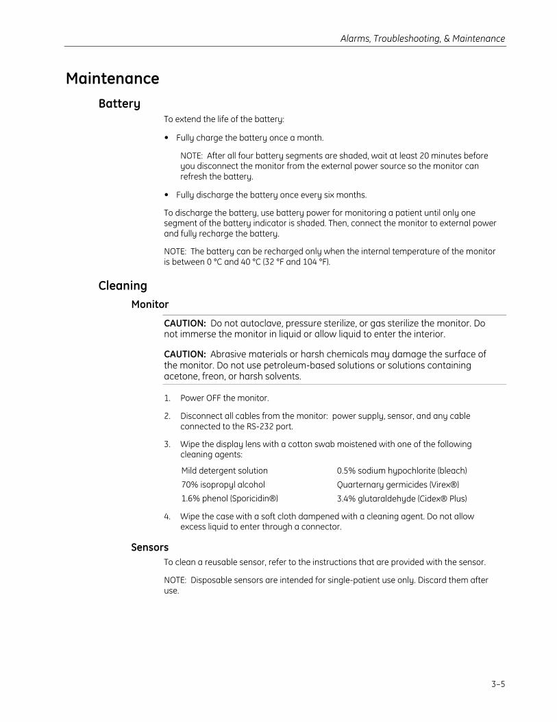
MaintenanceBattery
To extend the life of the battery:
• Fully charge the battery once a month.
NOTE: After all four battery segments are shaded, wait at least 20 minutes beforeyou disconnect the monitor from the external power source so the monitor canrefresh the battery.
• Fully discharge the battery once every six months.
To discharge the battery, use battery power for monitoring a patient until only onesegment of the battery indicator is shaded. Then, connect the monitor to external powerand fully recharge the battery.
NOTE: The battery can be recharged only when the internal temperature of the monitoris between 0 °C and 40 °C (32 °F and 104 °F).
CleaningMonitor
CAUTION: Do not autoclave, pressure sterilize, or gas sterilize the monitor. Donot immerse the monitor in liquid or allow liquid to enter the interior.
CAUTION: Abrasive materials or harsh chemicals may damage the surface ofthe monitor. Do not use petroleum-based solutions or solutions containingacetone, freon, or harsh solvents.
1. Power OFF the monitor.
2. Disconnect all cables from the monitor: power supply, sensor, and any cableconnected to the RS-232 port.
3. Wipe the display lens with a cotton swab moistened with one of the followingcleaning agents:
Mild detergent solution 0.5% sodium hypochlorite (bleach)
70% isopropyl alcohol Quarternary germicides (Virex®)
1.6% phenol (Sporicidin®) 3.4% glutaraldehyde (Cidex® Plus)
4. Wipe the case with a soft cloth dampened with a cleaning agent. Do not allowexcess liquid to enter through a connector.
SensorsTo clean a reusable sensor, refer to the instructions that are provided with the sensor.
NOTE: Disposable sensors are intended for single-patient use only. Discard them afteruse.
TruSat User’s Guide
3–6
Supplies and accessoriesAll monitor configurations include a power supply and a power cord. Monitorsconfigured with the Trend Download option also include the Trend Downloadsoftware CD and the TruSat/PC RS-232 cable.
Service kits and replacement parts are also available. They are listed in the TruSatTechnical Reference Manual.
SensorsRefer to the sensor chart that accompanies this manual for a list of the sensorsand sensor-related accessories approved for use with this monitor. Only OxyTip+sensors can be used with this monitor.
TruSat pulse oximetersTruSat, yellow ........................................................................................................6051-0000-190
TruSat, white ..........................................................................................................6051-0000-192
TruSat with Trend Download option, yellow..........................................6051-0000-191
TruSat with Trend Download option, white ............................................6051-0000-193
MiscellaneousPole mount..............................................................................................................6050-0007-197
Carrying case, nylon..........................................................................................6050-0006-585
Battery pack...........................................................................................................6050-0006-578
For installation by authorized service personnel only.
Power supply (AC to DC converter).............................................................6050-0006-579
Power supply (optional)for use with 12 VDC vehicle cigarette lighter ...............................6021-0000-042
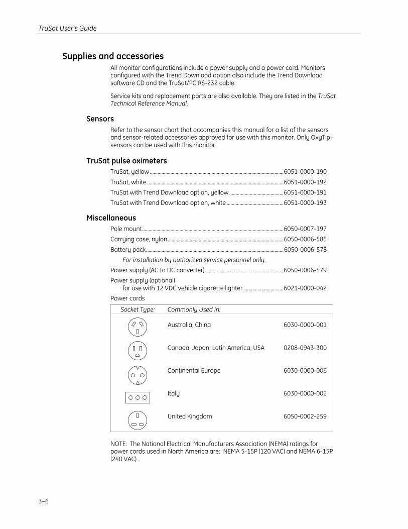
Power cords
Socket Type: Commonly Used In:
Australia, China
Canada, Japan, Latin America, USA
Continental Europe
Italy
United Kingdom
6030-0000-001
0208-0943-300
6030-0000-006
6030-0000-002
6050-0002-259
NOTE: The National Electrical Manufacturers Association (NEMA) ratings forpower cords used in North America are: NEMA 5-15P (120 VAC) and NEMA 6-15P(240 VAC).
Alarms, Troubleshooting, & Maintenance
3–7
Trend Download optionTrend Download option, upgrade kit......................................................... 6050-0007-164
For installation by authorized service personnel only.
Includes Trend Download software CD, TruSat/PC RS-232 cable,circuit board with RS-232 connector, and installation hardware
Trend Download software CD....................................................................... 6050-0006-586
Cable, TruSat/PC RS-232 ................................................................................. 6050-0006-924
Cable, TruSat/serial printer............................................................................. 6050-0006-925
Printer assemblyUS....................................................................................................................... 6050-0007-165Europe ............................................................................................................. 6050-0007-167Japan............................................................................................................... 6050-0007-166
NOTE: Each printer assembly includes:Serial printer and instructionsCable, TruSat/serial printerPrinter paper, 1 rollPrinter battery packPrinter power supply (US, Europe, or Japan)
Printer paper, 5 rolls........................................................................................... 6002-0000-200
Printer battery pack........................................................................................... 6002-0000-203
Printer power supplyUS....................................................................................................................... 6002-0000-199Europe ............................................................................................................. 6002-0000-201Japan............................................................................................................... 6002-0000-202
TruSat manualsTechnical Reference Manual, English......................................................... 6050-0006-813
User’s Guide
Czech................................................................................................................ 6050-0007-242Danish.............................................................................................................. 6050-0006-817Dutch................................................................................................................ 6050-0006-819English ............................................................................................................. 6050-0006-815Finnish ............................................................................................................. 6050-0006-821French.............................................................................................................. 6050-0006-823German........................................................................................................... 6050-0006-825Hungarian...................................................................................................... 6050-0007-244Italian ............................................................................................................... 6050-0006-827Japanese........................................................................................................ 6050-0006-829Norwegian..................................................................................................... 6050-0007-332Polish................................................................................................................ 6050-0006-831Portuguese.................................................................................................... 6050-0006-833Russian............................................................................................................ 6050-0007-246Spanish ........................................................................................................... 6050-0006-835Swedish........................................................................................................... 6050-0006-837


4–1
4. COMPLIANCE AND SPECIFICATIONSThis chapter contains:
• Medical electrical equipment standards and compliance information for the monitor.
• Specifications.
ComplianceEuropean Union Medical Device Directive 93/42/EEC: Class IIb
EN 60601-1 Medical electrical equipment – Part 1: General requirements for safety(including Amendments 1 and 2)
• Type of protection against electric shock: Class I equipment/Internal electrical powersource
• Degree of protection against electric shock: Defibrillation-proof type BF applied part
• Degree of protection against ingress of water (EN 60529): IPX2
• Not suitable for use in the presence of flammable anesthetic mixtures
• Mode of operation: Continuous
EN 60601-1-2 (2nd Edition) Electromagnetic compatibility – Requirements and tests
CISPR 11/EN 55011 (Protection against emissions): Group I, Class B
IEC 60601-1-8 Alarm systems – General requirements, tests and guidance for alarmsystems in medical electrical equipment and systems
Medical electrical equipment classified in the US and Canada with respect toelectric shock, fire, and mechanical hazards only, in accordance with theCanadian Standards Association CAN/CSA C22.2 No. 601.1 and UnderwritersLaboratories Inc. UL 2601–1.
TruSat User’s Guide
4–2
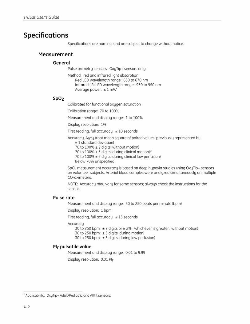
SpecificationsSpecifications are nominal and are subject to change without notice.
MeasurementGeneral
Pulse oximetry sensors: OxyTip+ sensors only
Method: red and infrared light absorptionRed LED wavelength range: 650 to 670 nmInfrared (IR) LED wavelength range: 930 to 950 nmAverage power: ≤ 1 mW
SpO2Calibrated for functional oxygen saturation
Calibration range: 70 to 100%
Measurement and display range: 1 to 100%
Display resolution: 1%
First reading, full accuracy: ≤ 10 seconds
Accuracy, Arms (root mean square of paired values; previously represented by± 1 standard deviation)70 to 100% ± 2 digits (without motion)70 to 100% ± 3 digits (during clinical motion) 2
70 to 100% ± 2 digits (during clinical low perfusion)Below 70% unspecified
SpO2 measurement accuracy is based on deep hypoxia studies using OxyTip+ sensorson volunteer subjects. Arterial blood samples were analyzed simultaneously on multipleCO-oximeters.
NOTE: Accuracy may vary for some sensors; always check the instructions for thesensor.
Pulse rateMeasurement and display range: 30 to 250 beats per minute (bpm)
Display resolution: 1 bpm
First reading, full accuracy: ≤ 15 seconds
Accuracy30 to 250 bpm: ± 2 digits or ± 2%, whichever is greater, (without motion)30 to 250 bpm: ± 5 digits (during motion)30 to 250 bpm: ± 3 digits (during low perfusion)
PIr pulsatile valueMeasurement and display range: 0.01 to 9.99
Display resolution: 0.01 PIr
2 Applicability: OxyTip+ Adult/Pediatric and AllFit sensors.
Compliance and Specifications
4–3
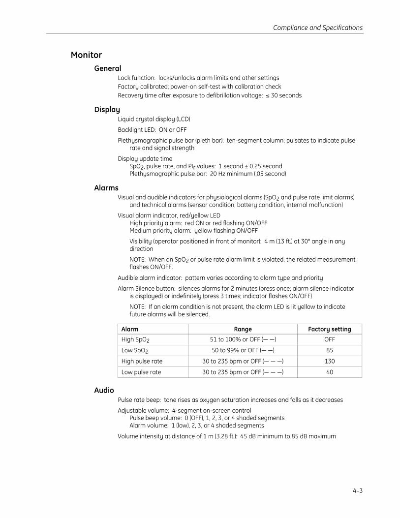
MonitorGeneral
Lock function: locks/unlocks alarm limits and other settingsFactory calibrated; power-on self-test with calibration checkRecovery time after exposure to defibrillation voltage: ≤ 30 seconds
DisplayLiquid crystal display (LCD)
Backlight LED: ON or OFF
Plethysmographic pulse bar (pleth bar): ten-segment column; pulsates to indicate pulserate and signal strength
Display update timeSpO2, pulse rate, and PIr values: 1 second ± 0.25 secondPlethysmographic pulse bar: 20 Hz minimum (.05 second)
AlarmsVisual and audible indicators for physiological alarms (SpO2 and pulse rate limit alarms)
and technical alarms (sensor condition, battery condition, internal malfunction)
Visual alarm indicator, red/yellow LEDHigh priority alarm: red ON or red flashing ON/OFFMedium priority alarm: yellow flashing ON/OFF
Visibility (operator positioned in front of monitor): 4 m (13 ft.) at 30° angle in anydirection
NOTE: When an SpO2 or pulse rate alarm limit is violated, the related measurementflashes ON/OFF.
Audible alarm indicator: pattern varies according to alarm type and priority
Alarm Silence button: silences alarms for 2 minutes (press once; alarm silence indicatoris displayed) or indefinitely (press 3 times; indicator flashes ON/OFF)
NOTE: If an alarm condition is not present, the alarm LED is lit yellow to indicatefuture alarms will be silenced.
Alarm Range Factory setting
High SpO2 51 to 100% or OFF (— —) OFF
Low SpO2 50 to 99% or OFF (— —) 85
High pulse rate 30 to 235 bpm or OFF (— — —) 130
Low pulse rate 30 to 235 bpm or OFF (— — —) 40
AudioPulse rate beep: tone rises as oxygen saturation increases and falls as it decreases
Adjustable volume: 4-segment on-screen controlPulse beep volume: 0 (OFF), 1, 2, 3, or 4 shaded segmentsAlarm volume: 1 (low), 2, 3, or 4 shaded segments
Volume intensity at distance of 1 m (3.28 ft.): 45 dB minimum to 85 dB maximum
TruSat User’s Guide
4–4
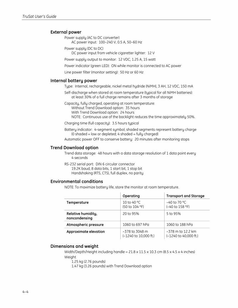
External powerPower supply (AC to DC converter)
AC power input: 100–240 V, 0.5 A, 50–60 Hz
Power supply (DC to DC)DC power input from vehicle cigaretter lighter: 12 V
Power supply output to monitor: 12 VDC, 1.25 A, 15 watt
Power indicator (green LED): ON while monitor is connected to AC power
Line power filter (monitor setting): 50 Hz or 60 Hz
Internal battery powerType: Internal, rechargeable, nickel metal hydride (NiMH), 3 AH, 12 VDC, 150 mA
Self-discharge when stored at room temperature (typical for all NiMH batteries):at least 30% of a full charge remains after 3 months of storage
Capacity, fully charged, operating at room temperature:Without Trend Download option: 35 hoursWith Trend Download option: 24 hoursNOTE: Continuous use of the backlight reduces the time approximately 50%.
Charging time (full capacity): 3.5 hours typical
Battery indicator: 4-segment symbol; shaded segments represent battery charge(0 shaded = low or depleted; 4 shaded = fully charged)
Automatic power OFF to conserve battery: 20 minutes after monitoring stops
Trend Download optionTrend data storage: 48 hours with a data storage resolution of 1 data point every
4 seconds
RS-232 serial port: DIN 6 circular connector19.2K baud, 8 data bits, 1 start bit, 1 stop bitHandshaking (RTS, CTS), full duplex, no parity
Environmental conditionsNOTE: To maximize battery life, store the monitor at room temperature.
Operating Transport and Storage
Temperature 10 to 40 ºC(50 to 104 ºF)
–40 to 70 ºC(–40 to 158 ºF)
Relative humidity,noncondensing
20 to 95% 5 to 95%
Atmospheric pressure 1060 to 697 hPa 1060 to 188 hPa
Approximate elevation –378 to 3048 m(–1240 to 10,000 ft.)
–378 m to 12.2 km(–1240 to 40,000 ft.)
Dimensions and weightWidth/Depth/Height including handle = 21.8 x 11.5 x 10.3 cm (8.5 x 4.5 x 4 inches)Weight
1.25 kg (2.76 pounds)1.47 kg (3.26 pounds) with Trend Download option
A–1
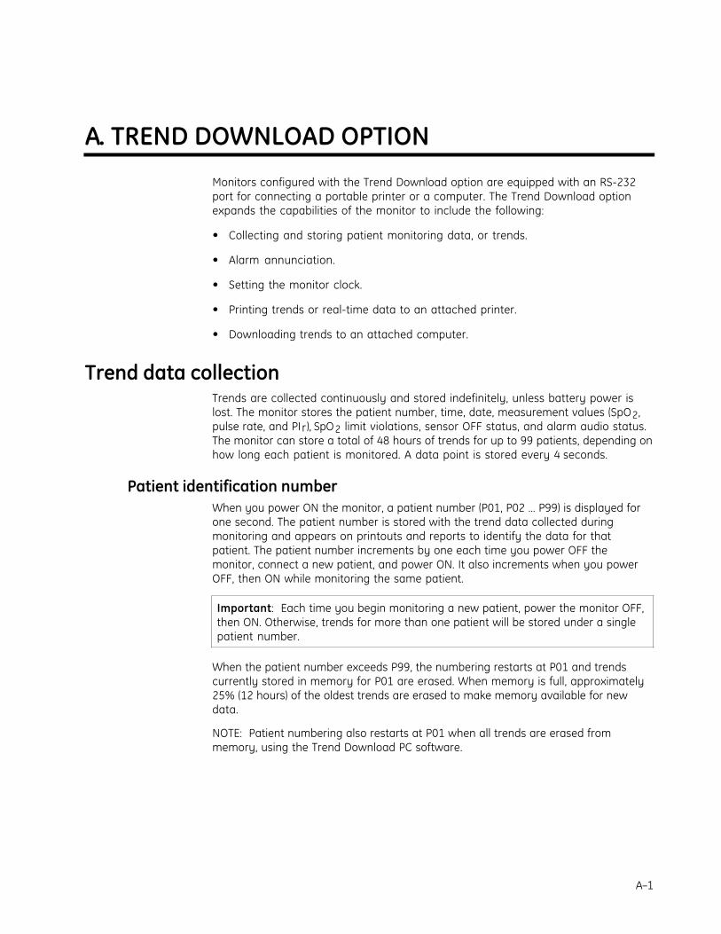
A. TREND DOWNLOAD OPTION
Monitors configured with the Trend Download option are equipped with an RS-232port for connecting a portable printer or a computer. The Trend Download optionexpands the capabilities of the monitor to include the following:
• Collecting and storing patient monitoring data, or trends.
• Alarm annunciation.
• Setting the monitor clock.
• Printing trends or real-time data to an attached printer.
• Downloading trends to an attached computer.
Trend data collectionTrends are collected continuously and stored indefinitely, unless battery power islost. The monitor stores the patient number, time, date, measurement values (SpO2,pulse rate, and PIr), SpO2 limit violations, sensor OFF status, and alarm audio status.The monitor can store a total of 48 hours of trends for up to 99 patients, depending onhow long each patient is monitored. A data point is stored every 4 seconds.
Patient identification numberWhen you power ON the monitor, a patient number (P01, P02 … P99) is displayed forone second. The patient number is stored with the trend data collected duringmonitoring and appears on printouts and reports to identify the data for thatpatient. The patient number increments by one each time you power OFF themonitor, connect a new patient, and power ON. It also increments when you powerOFF, then ON while monitoring the same patient.
Important: Each time you begin monitoring a new patient, power the monitor OFF,then ON. Otherwise, trends for more than one patient will be stored under a singlepatient number.
When the patient number exceeds P99, the numbering restarts at P01 and trendscurrently stored in memory for P01 are erased. When memory is full, approximately25% (12 hours) of the oldest trends are erased to make memory available for newdata.
NOTE: Patient numbering also restarts at P01 when all trends are erased frommemory, using the Trend Download PC software.
TruSat User’s Guide
A–2
Alarm annunciation capabilityThe Trend Download option lets you connect the TruSat to your local “nurse call”system for automatic transmission of signals when alarms occur. To enable thisfeature, authorized service personnel must do the following:
• Customize a cable for connecting your system to the TruSat.
• Change the position of a switch on the Trend Download board.
Instructions are located in the TruSat Technical Reference Manual.
WARNING: Alarm annunciation is not functional while alarms are silencedand should never be used as the main notification of an alarm condition. Analarm condition can be determined only by evaluating the clinical conditionof the patient together with audible and visual alarm signals.
Setting the clockThe date and time are included on printouts and with data downloaded to a PC.Clock settings are stored indefinitely unless battery power is lost.
Important: Set the clock before you begin monitoring to ensure that all patientrecords contain the correct time and date.
NOTE: You can also use the Trend Download PC software to set the clock.
1. Unplug the sensor from the monitor and power ON.
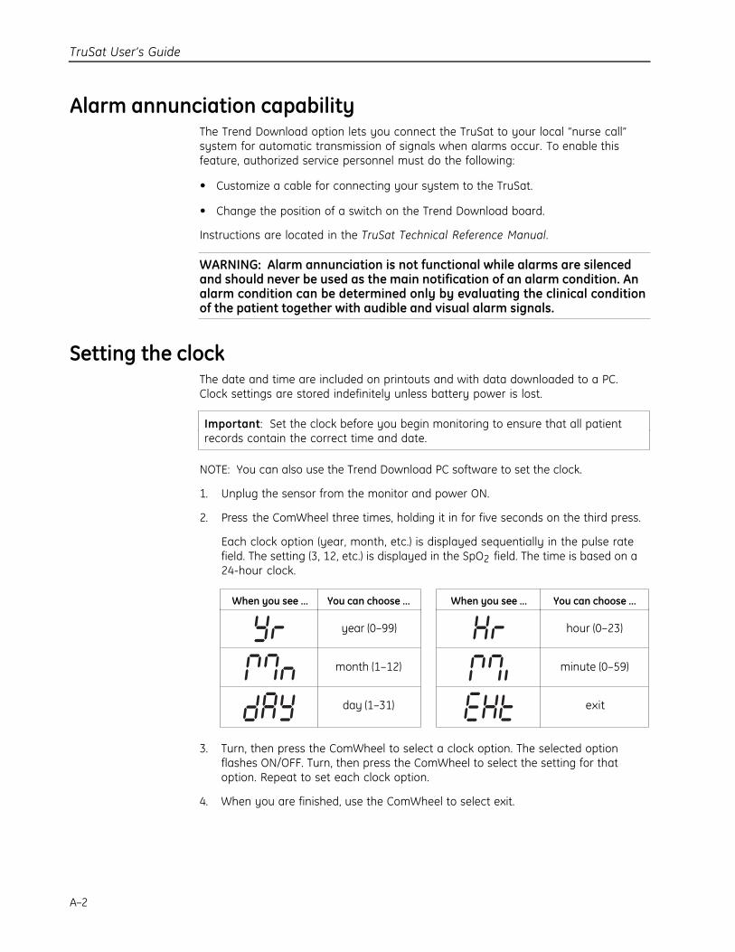
2. Press the ComWheel three times, holding it in for five seconds on the third press.
Each clock option (year, month, etc.) is displayed sequentially in the pulse ratefield. The setting (3, 12, etc.) is displayed in the SpO2 field. The time is based on a24-hour clock.
When you see … You can choose … When you see … You can choose …
year (0–99) hour (0–23)
month (1–12) minute (0–59)
day (1–31) exit
3. Turn, then press the ComWheel to select a clock option. The selected optionflashes ON/OFF. Turn, then press the ComWheel to select the setting for thatoption. Repeat to set each clock option.
4. When you are finished, use the ComWheel to select exit.

Trend Download Option
A–3
Printing to the portable printerThe portable printer is optional. See Supplies and accessories for orderinginformation. Refer to the instructions that came with the printer for details regardingchanging the paper, clearing paper jams, DIP switch settings, etc.
NOTE: If you are unable to print, check the printer DIP switch settings in theinstructions for the printer.
Connecting the printerThe TruSat/serial printer cable, a roll of paper, a battery pack, and a power supply forthe printer are included with the printer.
WARNING: When you connect equipment to the monitor, you areconfiguring a medical system and are responsible for ensuring that thesystem complies with IEC 60601–1–1 and with local requirements. Connectonly external devices specified for use with this monitor.
1. Connect the TruSat/serial printer cable to the monitor and to the printer.
2. Connect the printer power supply to the printer and to the AC power outlet.
3. Power ON the printer.
Important: Make sure a sufficient amount of paper is installed in the printer beforeyou begin printing. After printing, photocopy the printout for your records.Exposure to heat or light can destroy thermal paper printouts.
Paper coverPaper cover window
Power lamp
Power switch
TruSat User’s Guide
A–4
Printing summary statistics for one or more patientsYou can print a statistical summary of each record stored in the monitor. Trends forthe most recent patient are printed first.
1. After monitoring one or more patients, unplug the sensor from the monitor.NOTE: Press the Alarm Silence button to silence alarms.
2. Connect the printer.
3. To start printing, use the ComWheel to move the pointer to the printsymbol, then press the ComWheel. Repeat to stop printing.The print symbol is displayed during printing.
Important: The monitor calculates the data before printing begins. When printinga long record for a single patient, printing will be delayed approximately1 minute for every 24 hours of data. The monitor may appear to be inactive,however, printing will begin when the calculation is completed.
Sample printout: Summary statistics
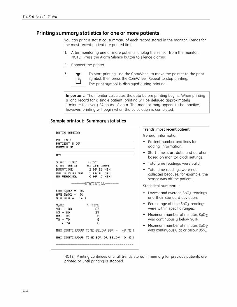
Trends, most recent patient
General information:
• Patient number and lines foradding information.
• Start time, start date, and duration,based on monitor clock settings.
• Total time readings were valid.
• Total time readings were notcollected because, for example, thesensor was off the patient.
Statistical summary:
• Lowest and average SpO2 readingsand their standard deviation.
• Percentage of time SpO2 readingswere within specific ranges.
• Maximum number of minutes SpO2was continuously below 90%.
• Maximum number of minutes SpO2was continuously at or below 85%.
NOTE: Printing continues until all trends stored in memory for previous patients areprinted or until printing is stopped.
Trend Download Option
A–5
Printing real-time dataReal-time printouts are intended for archival or record-keeping purposes only. Thepatient record is also stored in trend memory.
1. Connect the printer and begin to monitor the patient.
2. To start printing, use the ComWheel to move the pointer to the printsymbol, then press the ComWheel. Repeat to stop printing.The print symbol is displayed during printing.
Sample printout: Real-time data
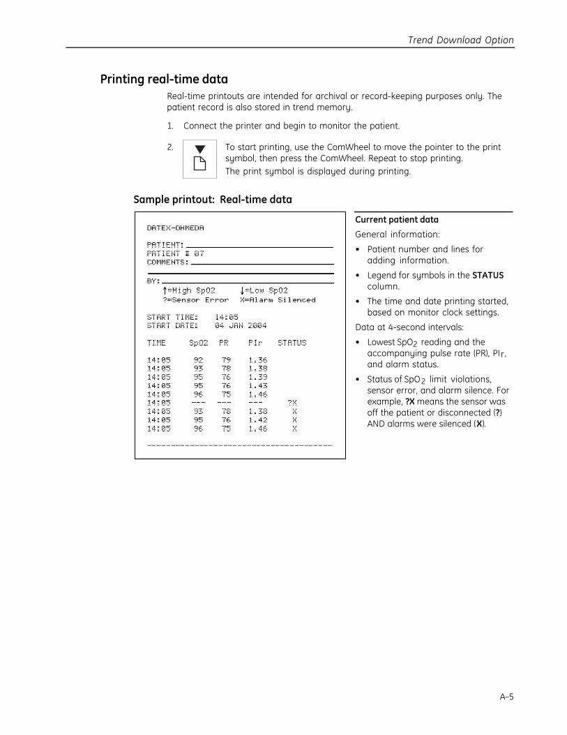
Current patient data
General information:
• Patient number and lines foradding information.
• Legend for symbols in the STATUScolumn.
• The time and date printing started,based on monitor clock settings.
Data at 4-second intervals:
• Lowest SpO2 reading and theaccompanying pulse rate (PR), PIr,and alarm status.
• Status of SpO2 limit violations,sensor error, and alarm silence. Forexample, ?X means the sensor wasoff the patient or disconnected (?)AND alarms were silenced (X).
TruSat User’s Guide
A–6
Trend Download PC softwareThe Trend Download (TD) software lets you access data stored on themonitor and download that data to a connected personal computer.You can create detailed, easy-to-read reports containing trends forindividual patients.
The Trend Download option includes the following equipment for connecting a PC tothe TruSat and downloading trends:
• Compact disc (CD) containing the Trend Download PC software and instructions(pdf).
• TruSat/PC RS-232 cable.
NOTE: The Trend Download PC program interface (menus, messages, etc.) is inEnglish.
PC requirements• Microsoft® Windows® 2000 and XP
• Intel® Pentium® 90 MHz processor (minimum)
• 32 MB RAM and at least 4 MB available on the hard drive
• CD-ROM drive
Software installation1. Power ON the PC and insert the Trend Download CD into the CD drive.
A start-up screen is displayed. If the start-up screen is not displayed, select theCD drive and open the CD. Then, double-click Setup.exe to display the screen.
2. Follow the prompts to install the software:
C:\Program Files\Datex-Ohmeda\Trend Download
You may select a different location, if desired.
Trend Download Option
A–7
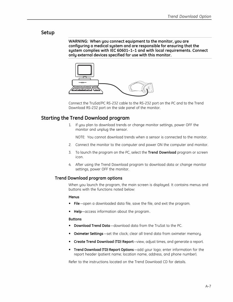
Setup
WARNING: When you connect equipment to the monitor, you areconfiguring a medical system and are responsible for ensuring that thesystem complies with IEC 60601–1–1 and with local requirements. Connectonly external devices specified for use with this monitor.
Connect the TruSat/PC RS-232 cable to the RS-232 port on the PC and to the TrendDownload RS-232 port on the side panel of the monitor.
Starting the Trend Download program1. If you plan to download trends or change monitor settings, power OFF the
monitor and unplug the sensor.
NOTE: You cannot download trends when a sensor is connected to the monitor.
2. Connect the monitor to the computer and power ON the computer and monitor.
3. To launch the program on the PC, select the Trend Download program or screenicon.
4. After using the Trend Download program to download data or change monitorsettings, power OFF the monitor.
Trend Download program optionsWhen you launch the program, the main screen is displayed. It contains menus andbuttons with the functions noted below:
Menus
• File—open a downloaded data file, save the file, and exit the program.
• Help—access information about the program .
Buttons
• Download Trend Data—download data from the TruSat to the PC.
• Oximeter Settings—set the clock; clear all trend data from oximeter memory.
• Create Trend Download (TD) Report—view, adjust times, and generate a report.
• Trend Download (TD) Report Options—add your logo; enter information for thereport header (patient name; location name, address, and phone number).
Refer to the instructions located on the Trend Download CD for details.


B–1
B. WARRANTY
The TruSat pulse oximeter (the Product) is sold by GE Healthcare (the Company) only underthe warranties set forth in the following paragraphs. Such warranties are extended onlywith respect to the purchase of the Product directly from the Company’s Authorized Dealersas new merchandise and are extended to the first buyer thereof, other than for resale. TheCompany warrants that the Product meets the published specifications at the time ofshipment from the factory.
Products not under warrantyThe following items are not covered under this warranty: disposable items, accessories,service kits, and replacement parts. These items may be covered under a separate warranty.Consult the Company for details.
DurationThe Product is warranted against defects in materials and workmanship for a period ofthree (3) years from the date of delivery to the user (in no event for a period of more than four[4] years from the date of original delivery by the Company to an Authorized Dealer). Theinternal battery is warranted against defects in materials and workmanship for a period ofone (1) year from the date of delivery to the user.
If any part of the Product proves defective under proper and normal use within the warrantyperiod, as the purchaser's exclusive remedy, the Company will repair or replace, at its solediscretion, the Product or any defective part provided it is returned to an authorized ServiceCenter within 30 days of the failure.
LimitationThe Company may at any time discharge its warranty obligation by repairing andreturning the Product to original factory performance. This may be accomplished byinstalling new or remanufactured assemblies or by other repairs deemed appropriate by theCompany. The choice of repair or replacement by the Company shall be the sole remedy ofthe buyer or user.
This warranty is valid only when qualified personnel have performed installation andservice on the Product and when all recommended planned maintenance procedures havebeen completed during the warranty period. Damage caused by the abuse or misuse of theProduct is not covered by this warranty. The Company shall not be liable for damageresulting from the improper installation or the misuse of the Product.
Exclusion of warrantiesOral statements about the Product do not constitute warranties, shall not be relied on bythe buyer or user, and are not part of any warranty extended by the Company.
Except as set forth in this limited warranty, the Company makes no warranties, expressed orimplied, including the implied warranty of merchantability and the implied warranty offitness for a particular purpose. Except for the obligations under this limited warranty, theCompany shall not have any obligation or liability for any incidental or consequentialdamages (including those from commercial loss) or other loss, damage, or injury resultingdirectly or indirectly from the Product.