Embed Size (px)
Citation preview

MG 334DB 230 (GB) 02.97Printed in Germany
GB
Operator's manual
PRECISON AIR SEEDER
ED 01ED 01ED 01ED 01ED 01

Copyright © 1996 by AMAZONEN-WERKEH. DREYER GmbH & Co. KGD-49202 Hasbergen-Gaste
All rights reserved

1
The AMAZONE ED is a seed drill from the extensiverange of agricultural machinery offered by AMAZONE.
Its sophisticated technology combined with proper usageoffers the most efficient application and design protection.
Please read the entire operator's manual carefully asany claims for damages due to misuse must be refused.
Enter the serial number of your seed drill in the spaceprovided. The number is located to the right of the fanhopper facing the machine.
Follow-up orders and any complaints should always beaccompanied by the machine type and serial number:
AMAZONE ED
with fertilizer drill
without fertilizer drill
Serial no:
Introduction:
This operator's manual should help you familiarizeyourself with the machine and its prescribed applications.
The operator's manual contains importantrecommendations for the safe, proper and economicoperation of the machine. Compliance with theserecommendations helps to prevent risks, reduce repaircosts and breakdown times and increase the service lifeof the machine.
The operator's manual is intended for use in conjunctionwith existing national accident prevention laws. Itshould be made available at all times at work locations.
Before starting work, the operator's manual must beread and practised by every person entrusted with theoperation of the machine. Only trained or instructedworkers may be employed to operate the machine andthe minimum age for workers must be observed.
Together with the operator's manual and mandatoryaccident prevention laws in the user country, anyrecognized special engineering regulations must beobserved (ie, to ensure safe and proper operation).
2
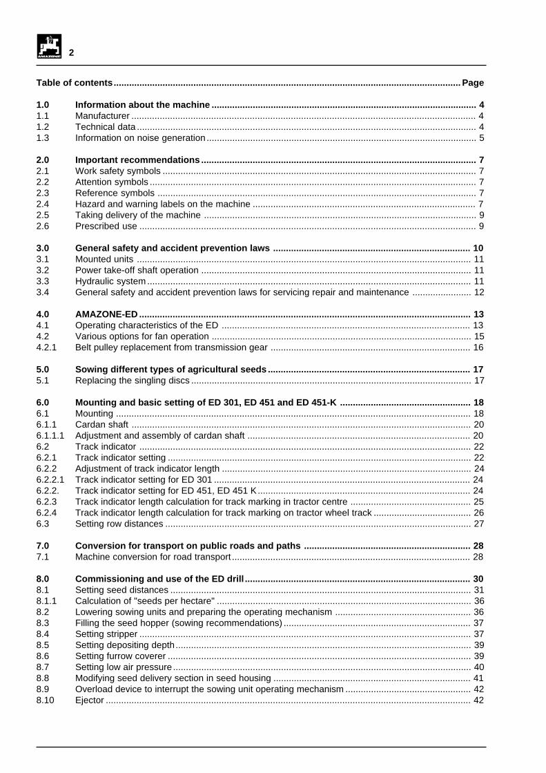
Table of contents....................................................................................................................................... Page
1.0 Information about the machine ....................................................................................................... 41.1 Manufacturer ...................................................................................................................................... 41.2 Technical data .................................................................................................................................... 41.3 Information on noise generation ......................................................................................................... 5
2.0 Important recommendations ........................................................................................................... 72.1 Work safety symbols .......................................................................................................................... 72.2 Attention symbols ............................................................................................................................... 72.3 Reference symbols ............................................................................................................................ 72.4 Hazard and warning labels on the machine ....................................................................................... 72.5 Taking delivery of the machine .......................................................................................................... 92.6 Prescribed use ................................................................................................................................... 9
3.0 General safety and accident prevention laws ............................................................................. 103.1 Mounted units .................................................................................................................................. 113.2 Power take-off shaft operation ......................................................................................................... 113.3 Hydraulic system .............................................................................................................................. 113.4 General safety and accident prevention laws for servicing repair and maintenance ....................... 12
4.0 AMAZONE-ED ................................................................................................................................. 134.1 Operating characteristics of the ED ................................................................................................. 134.2 Various options for fan operation ..................................................................................................... 154.2.1 Belt pulley replacement from transmission gear .............................................................................. 16
5.0 Sowing different types of agricultural seeds ............................................................................... 175.1 Replacing the singling discs ............................................................................................................. 17
6.0 Mounting and basic setting of ED 301, ED 451 and ED 451-K ................................................... 186.1 Mounting .......................................................................................................................................... 186.1.1 Cardan shaft .................................................................................................................................... 206.1.1.1 Adjustment and assembly of cardan shaft ....................................................................................... 206.2 Track indicator ................................................................................................................................. 226.2.1 Track indicator setting ...................................................................................................................... 226.2.2 Adjustment of track indicator length ................................................................................................. 246.2.2.1 Track indicator setting for ED 301 .................................................................................................... 246.2.2. Track indicator setting for ED 451, ED 451 K................................................................................... 246.2.3 Track indicator length calculation for track marking in tractor centre ............................................... 256.2.4 Track indicator length calculation for track marking on tractor wheel track ...................................... 266.3 Setting row distances ....................................................................................................................... 27
7.0 Conversion for transport on public roads and paths ................................................................. 287.1 Machine conversion for road transport ............................................................................................. 28
8.0 Commissioning and use of the ED drill ........................................................................................ 308.1 Setting seed distances ..................................................................................................................... 318.1.1 Calculation of "seeds per hectare" ................................................................................................... 368.2 Lowering sowing units and preparing the operating mechanism ..................................................... 368.3 Filling the seed hopper (sowing recommendations) ......................................................................... 378.4 Setting stripper ................................................................................................................................. 378.5 Setting depositing depth................................................................................................................... 398.6 Setting furrow coverer ...................................................................................................................... 398.7 Setting low air pressure .................................................................................................................... 408.8 Modifying seed delivery section in seed housing ............................................................................. 418.9 Overload device to interrupt the sowing unit operating mechanism ................................................. 428.10 Ejector .............................................................................................................................................. 42
3
Table of contents....................................................................................................................................... Page
9.0 After use ......................................................................................................................................... 439.1 Raising sowing units and interrupting power transmission............................................................... 439.2 Emptying seed hoppers ................................................................................................................... 439.3 Cleaning the machine ...................................................................................................................... 43
10.0 Commissioning fertiliser drill ........................................................................................................ 4410.1 Filling fertiliser hopper ...................................................................................................................... 4410.2 Raise fertilizer screen....................................................................................................................... 4410.3 Metering wheel drive ........................................................................................................................ 4410.4 Setting fertilizer delivery output ........................................................................................................ 4410.4.1 Setting gear lever ............................................................................................................................. 4510.4.2 Setting stop valves ........................................................................................................................... 4510.4.3 Setting bottom flaps ......................................................................................................................... 4510.5 Truing test to check fertilizer delivery output .................................................................................... 4610.6 Setting fertilizer coulters ................................................................................................................... 4710.7 Fertilizer delivery to outer fertilizer coulters in ED 451 and ED 451-K.............................................. 4710.8 Reduced working width by lifting outer sowing units on ED 451-K with fertilizer drill ....................... 4710.9 After use - emptying fertilizer hopper (for rapid fertilizer evacuation see special fitting) .................. 48
11.0 Servicing, repair and maintenance ............................................................................................... 4911.1 Threaded joints ................................................................................................................................ 4911.2 Cardan shaft .................................................................................................................................... 4911.3 Multiple ribbed belt for fan drive unit ................................................................................................ 4911.4 Tyre pressure ................................................................................................................................... 5011.5 Chain drive ....................................................................................................................................... 5011.6 Singling discs and vacuuming .......................................................................................................... 5211.7 Oil level in infinitely variable change-speed gear for fertilizer delivery ............................................. 5211.8 Replacing coulter points in sowing and fertilizer coulters ................................................................. 5211.9 Cleaning suction fan impeller ........................................................................................................... 5311.10 Servicing table ................................................................................................................................. 53
12.0 Special fittings ................................................................................................................................ 5412.1 Singling discs ................................................................................................................................... 5412.2 Hydraulic switch unit for track indicator with connector .................................................................... 5412.2.1 Setting switch unit for track indicator ................................................................................................ 5512.2.2 Resetting hydraulic switch unit ......................................................................................................... 5512.3 Vertical, hydraulically activated raising of track indicator ................................................................. 5612.4 Drive for power take-off 700 rpm...................................................................................................... 5612.5 Drive for power take-off 540 rpm...................................................................................................... 5612.6 Drive for power take-off 1000 rpm.................................................................................................... 5612.7 Drill coulter for beans ....................................................................................................................... 5712.8 Free-running cardan shaft ................................................................................................................ 5712.9 4 spring-mounted track looseners .................................................................................................... 5712.10 Terra tyres 31 x 15.5/15 ................................................................................................................... 5712.11 Spring pressure adjustment of sowing units (per coulter) ................................................................ 5812.12 Loading platform .............................................................................................................................. 5812.13 Wheel stripper (set) .......................................................................................................................... 5812.14 Rear lighting ..................................................................................................................................... 5912.15 Front side lights ................................................................................................................................ 5912.16 Mulch seed fittings (per coulter) ....................................................................................................... 5912.17 Fertilizer coulter for mulch seed ....................................................................................................... 5912.18 Rapid fertilizer evacuation ................................................................................................................ 6012.19 ED fertilizer filling tube ..................................................................................................................... 61
4
1.0 Information about the machine
1.1 Manufacturer
AMAZONEN-WERKE, H. Dreyer GmbH & Co. KG, Postfach 51, D-49202 Hasbergen-Gaste
1.2 Technical data
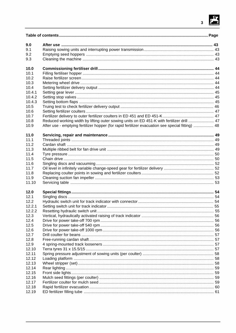
TYPE ED 301 ED 451-K ED 451
Tyres 6.00 -16 10.0/75-15 10.0/75-15 10.0/75-15
Transport width [m] 3 3 3 4
Length [m](pressure roller ø 370 mm)
2.1 2.1 2.1 2.1
Number of sowing units (standard) 4 4 6 6
Number of sowing units (max)without underfoot fertilizationwith underfoot fertilization
106
106
126
126
Row distance (standard) [cm] 75 75 75 75
Seed distance [cm]
36 stages
4.1 - 26.9
36 stages
4.1 - 26.9
36 stages
4.1 - 26.9
36 stages
4.1 - 26.9
Seed hopper contents [l] 32 32 32 32
Fan Suction fan cardan shaft speed 540 rpm, 700 rpm or1000 rpm (standard)
Singling element Plastic singling discs for corn, beans, peas, soya beans,sunflower seeds, cotton
Fertilizer hopper contents [l]
Fertilizer hopper cap + 200 l
450
650
450
650
450
650
450
650
Filling height (fertilizer) [m]with cap
1.431.59
1.431.59
1.431.59
1.431.59
Empty weightwithout fertilizerdrill [kg] from
Pressure rollerø 370 mmPressure rollerø500 mm
630
670
662
702
903
963
824
884
Empty weightwith fertilizerdrill [kg] from
Pressure rollerø 370 mmPressure rollerø500 mm
854
894
886
926
1177
1237
1098
1158

5
1.3 Information on noise generation
The emission level for work locations is 76 dB (A) whenmeasured with an OPTAC SLM 5 at the tractor driver'sear during machine operation with a closed cab.

6
Fig. 2.1
Fig. 2.2
D Vor Inbetriebnahme die Be-triebsanleitung und Sicher-heitshinweise lesen und be-achten.
F Lire le livret d'entretien etles conseils de sécuritéavant la mise en marche eten tenir compte pendant lefonction- nement.
GB Carefully read Operator'sManual before handling themachine. Observe instruct-ions and safety rules whenoperating.
NL Voor ingebruikname debedieningshandleiding ende veiligheidsvoorschriftenlezen en in acht nemen.

7
• Warnbildzeichen und Hinweisschilder immer sau-ber und in gut lesbarem Zustand halten! Beschädig-te oder fehlende Warnbildzeichen und Hinweisschil-der beim Händler anfordern und an der dafür vorge-sehenen Stelle anbringen! (Bild-Nr.: = Bestell-Nr.:)
• Fig. 2.1 und Fig. 2.2 zeigen die Befestigungsstellender Warnbildzeichen und Hinweisschilder. Die ent-sprechenden Erläuterungen finden Sie auf den fol-genden Seiten.
2.0 Important recommendations
2.1 Work safety symbols
This symbol is used in all work safetylabels to represent danger to life and limb.Observe the safety recommendations atall times and exercise particular caution inthese circumstances. Pass on any safetyrecommendations to other operators.Together with the recommendations in thisoperator's manual, general safety andaccident prevention regulations must beobserved.
2.2 Attention symbols
This symbol is found in locations whichrequire special care and attention to ensurecompliance with guidelines, regulations,recommendations and the correct workingprocedure and to prevent any damage tothe machine.
2.3 Reference symbols
This symbol identifies mechanicalcharacteristics which must be followed toensure proper operation.
2.4 Hazard and warning labels on themachine
• The hazard labels are found on danger points on themachine. Compliance with these hazard labelsensures the safety of all persons who operate themachine. Hazard labels are always accompaniedby work safety symbols.
• The reference symbols identify mechanicalcharacteristics which must be observed to ensurecorrect operation.
• All hazard signs and reference signs must be followedto the letter!
• Pass on all safety recommendations to other users!
I
F

8
MD 083
MD 084
MD 089
MD 093
D Vor Inbetriebnahme die Be-triebsanleitung und Sicher-heitshinweise lesen und be-achten.
F Lire le livret d'entretien et lesconseils de sécurité avant lamise en marche et en tenircompte pendant le fonction-nement.
GB Carefully read Operator'sManual before handling themachine. Observe instruct-ions and safety rules whenoperating.
NL Voor ingebruikname debedieningshandleiding en deveiligheidsvoorschriftenlezen en in acht nemen.
ME 489
MD 078
Sign no: MD 078
Explanation:
Keep away from nip and squeeze points if these includemoving parts!
Sign no: MD 082
Explanation:
Do not stand on the ladder or platform when vehicle isin motion!
MD 082
Sign no: MD 086
Explanation:
Before uncoupling remove locking devices!
MD 086
Sign no: ME 489
Explanation:
Read the operator's manual carefully before handlingthe machine and observe the safety recommendations!
Sign no: MD 093
Explanation:
Danger from rotating machine components (eg, cardanshaft)!
Never touch rotating shafts!
Sign no: MD 089
Explanation:
Do not stand below a raised unit (unsecured load)!
Sign no: MD 084
Explanation:
Do not stand near pivoted operating components!
Sign no: MD 083
Explanation:
Keep hands away from seed or fertilizer hopper andfilling tube. There is a risk of injury from the rotatingagitator shaft or filling tube!

9
Any arbitrary intervention carried out on the machineexcludes the manufacturer's liability for any damagecaused as a result.
Despite the care taken in the manufacture of the machine,the possibility of deviations in planting or total failurecannot be excluded even during prescribed use. Thismay be caused by:
- Variable composition of seed (seed size distribution,specific density, geometric shapes, dressing,sealing).
- Drift.- Blockages or bonding (eg, through foreign matter,
sack residues).- Unevenness on site.- Wear and tear of working parts (eg, singling discs).- Damage caused by external factors.- Incorrect drive speeds and engine running speed.- Incorrect setting of the machine (incorrect mounting).
Check the machine before and during use for correctoperation and seed planting accuracy.
Any claim for damages which is not directly related tothe seed drill is excluded. Liability for consequentialdamages from seed delivery errors is also excluded.Arbitrary modifications carried out on the drill may leadto consequential damages and excludes any liability onthe part of the supplier for such damages.
In the event of premeditation or gross negligence on thepart of the owner or a manager, and in such caseswhere a claim is made based on the Product Liability Actfor defects in the drill affecting persons or causingmaterial damage to privately used objects, the supplier'snon-liability is not applicable. Nor is it applicable for inthe absence of qualities which are expressly guaranteedif the guarantee's specific aim is to secure the purchaseragainst damage which is not caused directly by the drill.
2.5 Taking delivery of the machine
On delivery of the machine please check for any damageduring transit or missing parts! Compensation fordamages is awarded only if complaints are lodgedimmediately with the carrier. Check that all thecomponents listed in the consignment note are available.
Remove packaging and wires completely beforecommissioning and check lubrication (cardan shaft)!
When the machine is moved, the singlingdiscs of the sowing units and, in the caseof the fertilizer drill the agitator shaft of thefertilizer hopper, will start to rotate even in"0" gear position.
Therefore do not place any parts in theseed hopper or in the fertilizer hopper asthis may damage the singling discs andthe agitator shaft.
Do not place your hands in the seed orfertilizer hoppers. There is a risk of injuryfrom the rotating singling discs and agitatorshaft!
2.6 Prescribed use
The seed drills AMAZONE ED 301, ED 451 andED 451-K are designed exclusively for conventionalagricultural work. The seed machines are suitable forplanting corn, beans, peas, soya beans, sunflowers andcotton.
Any other application of the drill is unprescribed and themanufacturer is not liable for any damage resulting fromsuch use. The user bears full responsibility for suchrisks.
Prescribed use of the drill also incorporates compliancewith the manufacturer's operating, servicing and repairconditions together with the exclusive use of originalAMAZONE replacement parts .
The seed drills AMAZONE ED 301, ED 451 andED 451-K may only be used by, serviced and repairedby persons who are familiar with, and have beeninstructed in the operating dangers.
The relevant accident prevention laws together with anyother generally recognized safety, first aid and roadsafety regulations must be meticulously observed inconjunction with any safety instruction labels fixed to themachine.
I
I

10
16. Do not leave the driving position at any time whilstdriving!
17. Driving, steering and braking abilities are influencedby mounted or suspended equipment and ballastweights. Exercise care when steering and braking!
18. When lifting a three-point device the front axle ofthe tractor is differently balanced according to thesize. Observe the required front axle load (20% ofempty weight of tractor)!
19. When driving around corners take into account theclear radius and/or the rotating mass of themachine!
20. Operate the units only after all the safety deviceshave been mounted in position!
21. Standing in the operating area is prohibited!
22. Do not stand near rotating and swivelling parts ofthe machine!
23. Hydraulic folding frames must only be activated aftermaking sure no-one is standing near the machine!
24. Squeeze and shear points are found on externallyactivated components (eg, hydraulics)!
25. Before leaving the tractor leave the unit on theground, turn off the engine and remove the ignitionkey!
26. Standing between the tractor and the unit is notpermissible without ensuring that the parking brakeand/or tyre blocks have been applied to preventthe vehicle from rolling forward!
27. Lock the track indicators in the transport position!
28. Observe permissible filling quantities!
29. Do not place any foreign elements in the storagehoppers!
30. Watch out for hazard points from rotating machineparts during truing test!
31. Use the loading platform for filling operations only.Passengers are not permitted to travel on theplatform during operation!
3.0 General safety and accidentprevention laws
Basic rule:Before handling the drill and the tractor,check for road and operating safety!
1. In conjunction with the recommendations in theoperator's manual, observe any general safety andaccident prevention laws in force!
2. The hazard and warning signs provide importantinformation to ensure safe operation. They areintended for your safety!
3. Follow traffic regulations when using public roads!
4. Before starting work familiarize yourself with all theoperating elements and their uses. It will be toolate to do this whilst you are operating the machine!
5. The operator should wear close-fitting clothes.Avoid wearing loose-fitting clothes!
6. To avoid the risk of fire, keep the machine clean!
7. Before starting up and handling the machine checkthe immediate vicinity for clearance (children)!Make sure you have a clear view!
8. Carrying passengers whilst driving or operating themachine is not permitted!
9. Connect the units correctly and secure them onlyto the proper mounting devices!
10. Exercise special care when coupling anduncoupling units to or from the tractor!
11. Ensure that the landing gear is in the correct positionwhen mounting and dismounting (stability)!
12. Always attach weights correctly to the mountingpoints provided!
13. Observe the permissible axle loads, total weightsand transport dimensions!
14. Check and install any transport equipment such aslighting, warning devices and any safety devices!
15. Release cables for quick hitches should hang freelyand must not work loose from their housings!

11
8. When using the path-dependent power take-offshaft make sure that its speed is dependent on therunning speed and that the sense of direction isreversed when the vehicle is reversed!
9. Before switching on the power take-off shaft makesure that no-one is standing near the hazardousarea of the unit!
10. Never switch on the power take-off shaft when theengine is switched off!
11. When operating the power take-off shaft make sureno-one is standing near the rotating power take-offshaft or cardan shaft!
12. Always turn off the power take-off shaft for wideangles where it is not required!
13. Attention! There is a danger from the subsequentrotating force of the power take-off shaft afterswitching off!
Do not step too near the unit at this time! Startwork only when it has come to a standstill!
14. Clean, lubricate and adjust the power take-off drivenunit and the cardan shaft only after the power take-off shaft and the engine have been switched off andthe ignition key removed!
15. Attach the uncoupled cardan shaft to the bracketprovided!
16. After removing the cardan shaft place protectivecover on power take-off shaft end!
17. Rectify any damage immediately before operatingthe unit!
3.3 Hydraulic system
1. The hydraulic system is under high pressure!
2. When connecting hydraulic cylinders and motorsmake sure hydraulic hoses are connected asprescribed!
3. When connecting the hydraulic hoses to the tractorhydraulic system ensure that the hydraulics and thetractor is at zero pressure!
4. When carrying out hydraulic operations betweenthe tractor and the unit coupling sleeves andconnectors should be identified to prevent anyoperating errors.
If connections are mixed up reversed operations,eg, lifting instead of lowering, may cause accidents!
3.1 Mounted units
1. Before the mounting and dismounting of units tothe three-point linkage, position operating deviceto exclude any possibility of accidental lifting orlowering!
2. For the three-point linkage the mounting sectionsmust be correctly aligned between tractor and unit!
3. There is a danger from squeeze and shear pointsnear the three-point linkage!
4. Do not step between the tractor and the unit whenthe three-point linkage is activated externally!
5. Ensure that the tractor three-point linkage isadequately secured to the side when the unit is inthe transport position!
6. When the unit is raised for transport on public roads,the operating lever must be locked to prevent anyaccidental lowering!
7. Suspend/mount the units as specified. Check thetrailer brake system and observe the manufacturer'sinstructions!
3.2 Power take-off shaft operation
1. Only a cardan shaft prescribed by the manufacturerand fitted with the proper safety devices must beused!
2. A protective tube and hopper for the cardan shaftand protection for the power take-off shaft must beprovided and maintained in proper condition!
3. Apply coverings specified for transport and workpositions of cardan shaft (follow operator's manualof cardan shaft manufacturer!)
4. Mount and dismount the cardan shaft only whenthe power take-off shaft and the engine are switchedoff and the ignition key has been removed!
5. Always ensure that the cardan shaft has beencorrectly assembled and secured!
6. Prevent the cardan shaft rotating by suspendingchains!
7. Before switching on the power take-off shaft, makesure that the power take-off shaft speed of thetractor matches the permissible power take-off speed of the unit!

12
5. Check hydraulic hoses regularly and replace whendamaged or worn! Replacement hoses mustcomply with the manufacturer's requirements!
6. Use suitable tools when searching for leaks toprevent injury!
7. Under high pressure any fluids (such as hydraulicoil) may penetrate the skin and cause serious injury!In the event of injury call for a doctor immediately!There is a danger of infection!
8. Before starting work on the hydraulic system, lowerthe units, turn the system to zero pressure andswitch off the engine!
9. The service life of the hose assemblies should notexceed six years including a possible storage timeof 2 years at most. Even during proper storageand permissible stress, hoses and hoseconnections are subject to natural ageing whichlimits their storage and service life. By way ofexception, the service life may be determinedaccording to empirical values taking into accountthe risk of danger. Other standard values may beapplied to hoses and hose connections made ofthermoplastic material.
3.4 General safety and accidentprevention laws for servicing, repairand maintenance
1. Servicing, repair and cleaning operations togetherwith rectification of operating defects should onlybe carried out when the drive and the engine havebeen disconnected! Remove the ignition key!
2. Check nuts and bolts regularly for tightness andre-tighten if necessary!
3. When servicing a raised unit always ensure it issecured by suitable supports!
4. When replacing work tools by means of cuttingoperations, use a suitable implement and gloves!
5. Remove oil, grease and filter correctly!
6. Always disconnect power before starting work onthe electrical system!
7. Disconnect cable to the tractor generator andbattery when carrying out electric welding work onthe tractor and the mounted units!
8. When working on the tyres, make sure that themachine is stable and cannot roll away (tyre block)!
9. Repairs to the tyres may only be carried out byexperts using suitable tools!
10. Tyre assembly requires expert knowledge andspecific tools!
11. There is a danger of explosion if air pressure intyres is too high!
12. Check air pressure regularly!
13. Replacement parts must comply with themanufacturer's technical requirements! Thereforeoriginal replacement parts must be used!

13
4.0 AMAZONE-ED
The basic AMAZONE seed drill is the 4 row ED 301 witha three-point mounting frame. Attaching a fertilizer drill(Fig 4.1) is possible by simply mounting the fertilizer drillon the existing framework.
The basic machine includes up to 10 sowing units forplanting beans and peas. The seeds are deposited atequal intervals of 3 m. (see Chapter 6.4).
Seed drill models ED 451 and ED 451-K offer greatercapacity. The ED 451-K is characterised by an integralfolding mechanism for the outer sowing units, whilst theED 451 offers a working width of 4.5 m thanks to its 4 mwide frame. The fertilizer drill can also be easily mountedon both models.
If a fertilizer drill is retrofitted to the ED 451 or ED 451-K, an additional compressed air fan must be fitted to theexisting suction air fan to supply the outer fertilizercoulter with fertilizer.
4.1 Operating characteristics of the ED
The AMAZONE ED is a seed drill used for planting corn,soya beans, field beans, peas, dwarf beans, sunflowersand cotton. The singling discs of a sowing unit aredriven by a chain (4.2/1), a mechanical variable speedgear (4.2/2), cardan shaft (4.2/3) and secondarytransmission (4.2/4) via drive wheels (4.2/5). Thepower transmission from the drive shaft (4.2/6) to thesowing units and the singling discs (4.3/1) is carried outvia toothed wheels and a roller chain installed in thelower link (4.2/7) of the parallelogram wheel suspension.
Fig. 4.1
Fig. 4.2
3
2
8
4
6
7
1
5
1
2
3
Fig. 4.3

14
The seed is fed into the singling disc (4.3/1) via theopening (4.4/1) leading from the seed hopper. Thesingling assembly operates on an air suction principle.The low air pressure produced by the suction fan (4.2/8)draws the seeds from the seed hopper into the holes inthe singling discs.
The long filling section in the seed housing ensures thatall the holes in the singling disc are filled. The stripper(4.4/2), which can be adjusted to five different positions,singles the seeds drawn into the holes. Excess seedsfall back into the seed hopper. The singled seeds arethen fed through the seed housing to the ejector opening.If the seed reaches the lowest point the low air pressureis interrupted. The seed falls from the holes in thesingling discs directly into the furrow made by the drillcoulter (Fig 4.5). Any seeds which remain in the holesare carefully removed by the ejector for redistribution.
Easily replaceable plastic singling discs are availablefor the various types of seeds. The careful sealingbetween the singling disc and the suction cover (4.3/2)and the sealing between the singling disc and seedhousing (4.3/3) in the form of two different high-qualityplastics and foam material guarantee trouble-freeoperation and long life.
Fig. 4.3
Fig. 4.4
Fig. 4.5
1
2
3
3
2
1
10 c
m

15
4.2 Various options for fan operation
The fan (4.6/1) is fitted with a transmission gear (4.6/3)including a belt drive (4.6/2) and is driven by a cardanshaft from the tractor power take-off shaft. Through theuse of belt pulleys (4.6/4) of variable diameters "D", it ispossible to drive the input shaft (4.6/5) of the transmissiongear with various tractor power take-off speeds withoutchanging the speed of the fan drive. The gear case(4.7/1) of the transmission gear was removed fordemonstration purposes.
Operate machine only after the gear casehas been properly assembled!
Possible power take-off speeds and appropriatebelt pulley diameters:
a) Drive for power take-off shaft at 1000 rpm (standard)belt pulley diameter D = 178 mm, belt length 1105mm.
b) Drive for power take-off shaft at 700 rpm (reducedtractor engine speed)belt pulley diameter D = 255 mm, belt length 1244mm.
If the fan is driven at a reduced tractor engine speed
- connect the cardan shaft to the 1000 power take-off shaft of the tractor and
- install the belt pulley with a diameter of D = 255mm (special fitting).
c) Drive for power take-off shaft at 540 rpmbelt pulley diameter D = 330 mm, belt length 1397mm.
If the fan is driven at 540 rpm
- connect the cardan shaft to the 540 power take-off shaft of the tractor and
- install the belt pulley with a diameter of D = 330mm (special fitting).
Fig. 4.7
1
1
2
6
54
3
7
8
Fig. 4.6

16
4.2.1 Belt pulley replacement fromtransmission gear
The belt pulley (4.6/4) is attached to the input shaft(4.6/5) of the transmission gear with four bolts (4.6/6).The multiple ribbed belt (4.6/2) links the belt pulley to thefan drive shaft (4.6/7). The belt is tensioned with the aidof a spring-loaded roller (4.6/8).
The correct belt pretensioning is achievedwhen the tension spring is 260-5 mm long.
The replacement of the belt pulley is carried out asdescribed below:
• ED with suction fan:
- Remove the gear case after unscrewing the threebolts.
- Release belt pretensioning and remove multipleribbed belt.
- Unscrew bolts (4.6/6) and replace belt pulley.
• ED with compressed air fan and suction fan:
- Unscrew the 4 bolts in the retaining plate (4.9/1) ofthe compressed air fan and remove the retainingplate.
- Remove 3 sectioned case (4.9/2) after removingthreaded connections.
- Release belt pretensioning and remove multipleribbed belt.
- Unscrew bolts (4.6/6) and replace belt pulley.
Assembly is carried out in reverse.
The belt pulley replacement requires amultiple ribbed belt of a different length.
Pretension spring to length of 260 -5 mmonce again. Attach case!
Operate the machine only after all the safetydevices are in place !
1
1
1
Fig. 4.8
Fig. 4.9
1
2
1
2
6
54
3
7
8
Fig. 4.6
I
II

17
5.0 Sowing different types ofagricultural seeds
The AMAZONE ED is suitable for sowing corn seed,soya beans, field beans, peas, dwarf beans, sunflowersand cotton. Easily interchangeable singling discs (specialfittings) are available for singling these various types ofseeds.
5.1 Replacing singling discs
- Raise the sowing unit (see Chapter 9.1) or lift theentire seed drill.
When raising the machine, guard againstaccidental lowering!
- Unscrew rear bolt (5.1/1) from coulter bracket andswivel coulter downwards.
- Unscrew upper bolt (5.1/3) and rotate transparentplastic flap (5.1/4) to the right.
- Unscrew front bolt (5.1/5) and rear bolt (5.1/6) andremove suction cover (5.2/1).
- Remove suction cover together with the singling disc(5.2/2).
- Replace singling disc.
Examine the foam seal (5.2/3) for anydamage and replace if necessary.
The holes (5.2/4) should face the housing(5.2/5) not the suction cover (5.2/1).
- Assemble the singling disc and the suction coverand screw on the cover.
- Check workability of stripper (5.3/1) by tilting thelever (5.3/2) lightly several times (where the springis suspended)so that it is deflected from its resting position.
The spring should consistently return thestripper to its original position.
- Replace with a new stripper if required according totype of seed (see Chapter 8.4).
- Raise the coulter and secure it.
Fig. 5.1
1
2
3
4
5
6
2
Fig. 5.2
3
145
Fig. 5.3
1
2
II
F

18
6.0 Mounting and basic setting ofED 301, ED 451 and ED 451-K
6.1 Mounting
- Mount the AMAZONE ED to the rear three-pointhydraulic system of the tractor (see Chapter 3.1).Secure the lower link of the tractor with the aid of theED lower link bolts (category II).
- Secure the top link with the aid of insert bolts (categoryII).
Adjust the upper link length so that theseed hopper lids of the sowing units arehorizontal when the machine is in thelowered position and the drill coulters diginto the soil. Only if this setting is obtainedwill the drill coulter be positioned correctlyin the soil to produce trouble-free, uniformseeding.
The lower links of the tractor three-point hydrauliclinkage should be equipped with stabiliser bars orchains . When raised, the lower links of the tractorshould have a little slack to the side only to ensure thatthe machine remains in the centre behind the tractorduring sowing operations. This will guarantee uniformrow distances even on slopes and, during turningoperations on headlands, prevent the drill gettingknocked back and forth when raised.
As a rule additional front ballast must beprovided to obtain a sufficiently high frontaxle load (minimum of 20% of empty tractorweight).
The tractor should have sufficient reservesfor additional rear axle loading which isalready very high when the vehicle isempty! For this reason the vehicle mayonly be driven on public road unladen.
I

19
1
1
Fig. 6.1
I Tighten and secure locking devices (6.1/1)on mounted machine!
Before uncoupling the machine, releaselocking devices (6.2/1) and secure withspring-loaded bolts (6.2/2).
1
Fig. 6.2
2

20
6.1.1 Cardan shaft
The fan's transmission gear is driven via the cardanshaft from the tractor power take-off shaft.
The following cardan shafts are available:
a) standard cardan shaft
b) free-running cardan shaft (special fitting).
The latter is required if the seed drill is used in combinationwith an agricultural implement (eg, vibrating harrow,circular spike harrow or rotary cultivator) and a furrowpress since the fan drive is operated via the agriculturalimplement which, when the brake is applied, causes thefan impeller to stop abruptly due to its high speed whenthe power take-off shaft is switched off. A free-wheelingcardan shaft prevents damage to the cardan shaft andto the drive unit of the suction fan.
A free-wheeling cardan shaft is also required for tractorswith a hydraulically activated power take-off clutchsince the fan impeller is also subject to sudden braking.
6.1.1.1 Adjustment and assembly of cardan shaft
Insert the cardan shaft halves into the tractor powertake-off shaft connection and the power take-off end ofthe AMAZONE ED as indicated (see symbol on cardanshaft).
Clean the power take-off end on themachine in advance!
Use the cardan shafts specified by themanufacturer only!
Assemble the cardan shaft to the tractoras indicated in Fig 6.3. Since this procedureapplies to this type of tractor only, checkthe adjustment of the cardan shaft fordifferent tractor types.
During the initial assembly insert the cardan shafthalves into the power take-off shaft on the tractorwithout inserting the cardan shaft pipes into each other.
1. Whilst holding the cardan shaft pipes next to eachother, check to ensure that the transverse contactratio of the cardan shaft pipes is guaranteed whenthe machine is both raised and lowered at a minimumof 40% of LO (LO = length when pushed in).
III

21
2. When pushed together the cardan shaft pipes mustnot push against the forks of the universal joint. Asafety distance of 10 mm minimum must bemaintained.
3. To set the correct length hold the shaft halvestogether at the shortest working position and markout.
4. Cut off inner and outer pipe evenly.
5. Cut off inner and outer profile to the length of the pipeabove.
6. Round off cut edges and carefully remove swarf.
7. Grease profiles and insert into each other.
8. Hang the retaining chain to the lug on the top link toallow the cardan shaft sufficient play to work in alloperatingpositions and to ensure that the cardanshaft protector does not rotate during operation.
9. Operate the machine only after the drive is fullyprotected.
Only operate the cardan shaft after it hasbeen properly and safely mounted to thetractor and unit. Safety devices should bereplaced as soon as they become damaged.
The maximum angle of a universal joint inthe cardan shaft should not exceed 25°.
Observe the manufacturer's assembly and servicinginstructions indicated on the cardan shaft!
If the seed drill is used in combination withan agricultural implement and a furrowpress and the drill is raised above thefurrow press by a power lifting frame, alifting guard should be fitted to theagricultural implement so that the angle ofthe universal joint of the cardan shaft doesnot exceed 30°.
To prevent any damage to the cardan shaftand fan, the power take-off shaft should beengaged slowly at low tractor speeds only.
Fig. 6.3
I
F
I

22
6.2 Track indicator
The AMAZONE ED seed spacing drill is fitted with trackindicator discs (6.4/1) as standard.
When unfolded (Fig 6.4) the track indicator discs (6.4/2)dig into the soil continuously if the sowing unit is notfitted with an automatic switch unit (special fitting).
When the track indicator meets a solid obstacle theshearing bolt shears off thereby protecting the trackindicator from any damage.
Use bolts with a resistance of 8.8 onlywhen replacing the shearing bolt.
6.2.1 Track indicator setting
Set the track indicator discs so that they
- run parallel to the running direction on light soils
- work more aggressively on heavier soils to producea clearly visible track.
After loosening the locking screw (6.4/3) adjust theposition of the track indicator discs by turning the disc.
Fig. 6.4
Fig. 6.5
1
3
1
2
4
I

23
I Make sure that the track indicators do notdig too deeply into the soil. If the trackindicators are set too deeply there is adanger of damage from the rough, stonyseedbed.
The working depth of the track indicator discs shouldbe limited to 60 to 80 mm . For this purpose
- hang the chain (6.4/4 or 6.6/1) on the radial arm sothat it remains a little slack as soon as the trackindicator discs lie on the contact surface of the drivewheels.
- Secure the chain with the aid of the spring cotter onradial arm.
Various chain lengths can be obtained bysetting the chain at different chain links.
Lock the track indicators in their transportposition when travelling on public roads.
Secure the track indicators (6.7/1) in thistransport position with the aid of a split pin(6.7/2).
When raising and lowering the trackindicators, squeeze and shear points canbe found between the track indicator andthe machine frame. Do not touch theseareas as long as they contain potentiallymoving parts!
Never stand below a raised, unsecuredtrack indicator!
1
Fig. 6.6
2
1
Fig. 6.7
FII

24
6.2.2 Adjustment of track indicator length
To adjust their length, lower both track indicators.
The track indicator dimensions vary according to theworking width, row distance and number of rows of thedrill, ie, the distances from the contact surface of thetrack indicator disc on the soil to the centre of themachine or to the outer sowing unit.
6.2.2.1 Track indicator setting for ED 301
Length adjustment can only be carried outfrom tractor centre!
- Remove locking screws (6.8/1).- Extend radial arm (6.8/2) to required length.- Remove locking screw (6.8/3).- Extend track indicator disc (6.8/4) to precise length
required and rotate if necessary.- After adjustment tighten all locking screws.
6.2.2.2 Track indicator setting for ED 451, ED 451 K
Length adjustment can only be carried outfrom tractor track or tractor centre!
- Pull spring-loaded retainer and pull out radial arm(6.9/2) until the retainer (6.9/1) is again locked intoplace(adjustment for tractor track).
- For adjustment from the tractor centre pull the retainer(6.9/1) once again and pull out the radial arm furtheruntil the retainer (6.9/1) locks into place.
- To adjust precisely, loosen the locking screw (6.9/3),pull out the track indicator disc and rotate is necessary.
- Replace locking screw (6.9/3).
By activating the retainer (6.9/1) the radialarm (6.9/2) may be moved telescopically inand out of the radial arm (6.9/4) withoutchanging the length of the track indicators.The length of the track indicator extensionarm can be easily reduced for transportpurposes.
1
2
3 4
F
Fig. 6.8
Fig. 6.9
1
4
2
3
I
F
25
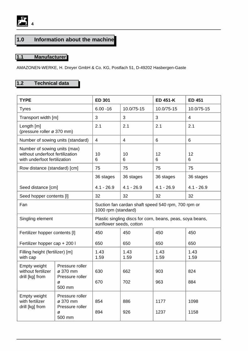
6.2.3 Track indicator length calculation fortrack marking in tractor centre (Fig 6.10)
The track indicator distance A measured from thecentre of the machine to the contact surface of the trackindicator disc on the soil represents the working width.
Track indicator distance A = R x n
R: row distancen: number of sowing units
Example :
Row distance R: 75 cmNumber of sowing units n: 4
Track indicator distance A = 75 cm x 4 = 300 cm
When the machine is raised and the trackindicators (ED 451) are folded up the heightof the machine is more than 4 m high.Reduce the length of the track indicatorsfor travelling on public roads (see Chapter6.2.2.2).
AR
Fig. 6.10 I

26
6.2.4 Track indicator length calculation fortrack marking on tractor wheel track
6.2.4.1 Measured from the centre of the machine(Fig 6.11)
Use the formulae below to calculate the correct trackindicator distances for symmetrical configuration of thecoulters from the centre of the machine:
Track indicator distance A
Working width B = number of rows n x row distance R
Track indicator distance A = R x n -
R: row distancen: number of sowing unitsS: tractor track
Example:
Row distance R : 75 cmNumber of sowing units n: 4tractor track S: 150 cm
= 4 x 75 cm - = 225 cm
6.2.4.2 Measured from outer coulter(Fig. 6.12)
Use the formulae below to calculate the correct trackindicator distances for symmetrical configuration of thecoulters:
Track indicator distance A =
R: row distancen: number of sowing unitsS: tractor track
Example:
Row distance R: 75 cmNumber of sowing units n: 4Tractor track S: 150 cm
= = 112,5 cm
A
S
R
Fig. 6.11
A
S
R
Fig. 6.12
tractor track S
2
150 cm2
2
R (n+1) - S
75 cm (4+1) - 150 cm 2
= working width B -
S2
Track indicatordistance A
Track indicatordistance A

27
6.3 Setting row distances
The row distances on the sowing units of the AMAZONEED may be progressively adjusted greater than 27 cmas follows:
- Remove grub screws from dust guard (6.13/1) onsowing units (6.13/2) and remove secondarytransmission(6.13/3).
- Remove the collar (6.13/4) on both outer sowingunits (on ED 301 and ED 451 only).
- Pull out hexagon shaft (6.13/5) if necessary.
- Loosen nuts (6.13/6) on retaining brackets (6.13/7).
- Push sowing units on to rail (6.13/8) as required.
- If the transmission gear (6.14/1), locking device(6.14/2) or track loosener (6.14/3) need displacing,releaseretaining brackets and move them.
- Tighten the nuts on the retaining brackets.
- Assemble the hexagon shaft where applicable.
- Push the collars (6.13/4) against the outer sowingunits and secure with grub screws (for ED 310 andED 451only).
- Tilt the grub screws of the dust guard against thesowing units and secondary transmission and tighten.
After operating the machine for 2 hourscheck screws for tightness.
.
1
6
84
5
2
3
7
Fig. 6.14
Fig. 6.13
1
2
3
I

28
7.0 Conversion for transport onpublic roads and paths
Please observe the following recommendationswhich are intended to prevent accidents on publicroads and paths.
As a rule, additional front ballast must beprovided to obtain a sufficiently high frontaxle load (minimum of 20% of empty tractorweight).
The tractor should have sufficient reservesfor additional rear axle loading which isalready very high when the vehicle isempty! For this reason the vehicle mayonly be driven on public road unladen.
If you use public roads and paths to reach seed fieldsboth the tractor and the machines must comply withStVZO regulations:
- Do not exceed the transport width of 3 m.
- Lighting and identification:
Lighting equipment and licence plate lamps(Fig. 7.1):
• Full rear lighting with rear reflectors and licenceplate lamps where applicable, additional frontside lamps at night.
Labelling:
• Warning labels to comply with DIN 11 030 orparking warning labels front and back, right andleft.
Parking warning labels, front side lamps, rear lights,rear reflectors and licence plate lamp hoppers areavailable as special fittings in a complete set.
The currently valid version of StVZO is authoritative.The equipment owner is responsible for the lightingand labelling of the equipment.
- Check the lighting system for reliability.
7.1 Machine conversion for roadtransport
- Lift the individual sowing units to their transportposition and secure.
Fig. 7.1
29
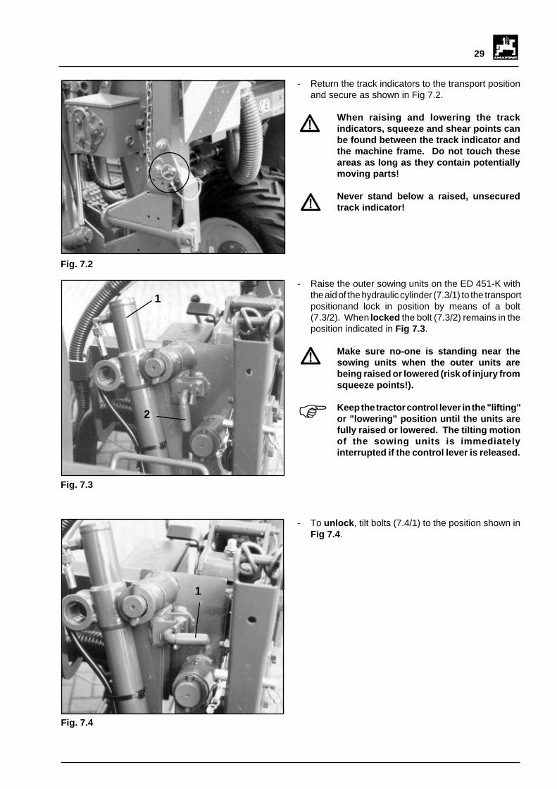
- Return the track indicators to the transport positionand secure as shown in Fig 7.2.
When raising and lowering the trackindicators, squeeze and shear points canbe found between the track indicator andthe machine frame. Do not touch theseareas as long as they contain potentiallymoving parts!
Never stand below a raised, unsecuredtrack indicator!
Fig. 7.2
Fig. 7.3
1
2
- To unlock , tilt bolts (7.4/1) to the position shown inFig 7.4 .
Fig. 7.4
1
F
- Raise the outer sowing units on the ED 451-K withthe aid of the hydraulic cylinder (7.3/1) to the transportpositionand lock in position by means of a bolt(7.3/2). When locked the bolt (7.3/2) remains in theposition indicated in Fig 7.3 .
Make sure no-one is standing near thesowing units when the outer units arebeing raised or lowered (risk of injury fromsqueeze points!).
Keep the tractor control lever in the "lifting"or "lowering" position until the units arefully raised or lowered. The tilting motionof the sowing units is immediatelyinterrupted if the control lever is released.

30
8.0 Commissioning and use of theED drill
For ED 301 and ED 451:
- Lower track indicator (Fig 8.1).- Check working depth of track indicator (see Chapter
6.2.1).
When lowered both track indicator discsare in the working position.
For the ED 451-K
- Release transport lock for outer sowing units andlower units hydraulically. When lowered the outersowing units are automatically hydraulically locked.
To lower the outer sowing units the tractormust be fitted with a dual-acting controlvalve.
Keep the tractor control lever in the "lifting"or "lowering" position until the units arefully raised or lowered. The tilting motionof the sowing units is immediatelyinterrupted if the control lever is released.
Fig. 8.1
Fig. 8.2
1
F
FF

31
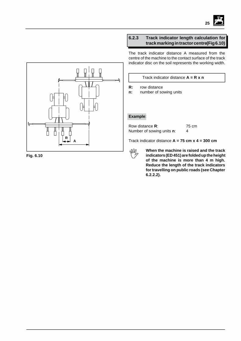
8.1 Setting seed distances
The seed distances in the row may be adjusted via thevariable speed gearbox (8.3/1) and secondarytransmission (8.3/2) by means of 36 fine graduationsfrom 4.1 to 26.9 cm and with the aid of the setting table(8.3/3).
Setting seed distances:
1. Select the area of the seed distance roughly byarranging the cardan shaft (8.3/4) in the "X" or "Y"inputs of thesecondary transmission (8.3/2).
2. Set the required seed distance by changing thetransmission in the gearbox (8.3/1).
To set the depositing depth the following informationmust be known:
1. Number of plants or seeds required per m2 (seedsper ha/10 000).
2. Row distance.
3. Number of holes in singling disc.
From the given number of seeds (plants) per m 2,obtain the seed distance "a" for the required rowdistance "R":
Taking into account the number of holes in the singlingdisc as shown in the setting table (8.4) (attached togearbox cover), look for the seed distance which comesnearest this amount and observe the relevant sprocketpairings.
1
23
4
Fig. 8.4
Fig. 8.3
ED / RP - ED 01Getriebeeinstelltabelle fürGearbox setting table forInsteltabel voor schakelkastTableau de réglage du boitier pour
VereinzelungsscheibeSingling discPrecisie-zaaischijfDisque sélecteur
12,99,97,0
13,910,7
7,5
14,911,48,1
15,912,2
8,6
16,912,9
9,1
17,913,79,7
7,65,74,1
8,26,24,4
9,37,15,0
8,76,64,7
9,97,65,3
10,48,05,6
ABC
ABC
grün, green,groen, vert
natur, natural,naturel, neutre
braun, brown,bruin, marron
schwarz, black,zwart, noir
orange, oranje
dunkel grau, dark-grey,donkergrijs,gris foncé
rot, red, rood, rouge
30 / 5
30 / 5,8
30 / 2,5 45 / 4
45 / 2,5
45 / 5
45 / 6
D
GB
NL
F
X
Y
30 45
45
XY
6 5 3 2 14
a
913 227
1 2 3 4 5 6
X
Y
BA
C
22,417,112,1
23,918,312,9
25,419,413,7
26,920,514,5
ABC
ABC
15,712,0
8,5
14,811,3
8,0
13,910,7
7,5
13,110,07,1
12,29,36,6
11,38,76,1
20,916,011,3
19,414,810,5
X
Y
30
XY
6 5 3 2 14
a
Seed distancea [cm] seeds per m² x row distance R [m]
1= x 100

32
22,417,112,1
23,918,312,9
25,419,413,7
26,920,514,5
ABC
ABC
15,712,08,5
14,811,38,0
13,910,7
7,5
13,110,07,1
12,29,36,6
11,38,76,1
20,916,011,3
19,414,810,5
X
Y
30
XY
6 5 3 2 14
a
2
4
5
6
7
3
Fig. 8.6
Fig. 8.5
1
1
Example:
Required: 95 000 seeds per haRow distance R: 0.75 mSingling disc: 30 holes
90 000 seeds per hectare: 10 000 = 9.5 seeds per m²
= 14,04 cm
Seed distance a: 14,04 cmSingling disc: 30 holes
Since this seed distance cannot be found in the table,select the nearest distance to it listed in the table.
Table: 13,9 cm
For a seed distance of 13.9 cm, the seed table (Fig8.5) indicates the following example:
Secondary transmission: YSprocket pairing: A - 3
Set the required seed distance as follows:
- Raise gearbox cover and secure it (8.6/1).- Remove crank (8.6/2) from the bracket (8.6/3), insert
in square tube (8.6/4) and release the chain (8.6/5)by turning the crank in an anti-clockwise directionuntil the spacer shaft (8.6/6) of the wire cable (8.6/7)is locked in position (Fig 8.7).
Seed distancea [cm] = x 100 cm
9,5 seeds pro m² x 0,75 m
Seed distancea [cm]

33
Fig. 8.8
Fig. 8.7
- Unlock the catch manually (8.8/1). Turn the tensionmechanism with the crank until you reach the endposition.
1
Spacer shaft locked in position.
1C
AB
Fig. 8.9
- Move drive-mounted lifter (8.9/1) and position thechain (8.9/2) on the required sprocket (A, B, C) withthe aid of the hook (8.9/3). After use replace hook inbracket on the gearbox.
2
3

34
Fig. 8.10
- Position the chain on the required sprocket (1 - 6) onthe power take-off side. Move the spacer shaft(8.10/7) to thecorrect position so that the chain is in alignment withthe sprockets and the guide rollers.
- Position the tip of the lifter (8.10/8) in the correct slot(8.10/9) of the axial safety plate (8.10/10).
1
3
2 4
5
6
78
109
- Use the crank to turn the tension mechanism back,guide the catch (8.11/1) back under the spacer shaft(8.11/2) and keep loosely locked in position.
Fig. 8.11
1
2
XY
1
Fig. 8.12
- Check the secondary transmission X/Y and changethe cardan shaft (8.12/1) if applicable.

35
- Pull the spacer shaft (Fig 8.13/1) slightly out of theslot (8.12/2) with the aid of the crank, then lift it out ofthe slot by pressing the catch (8.12/3) down.
Keep a firm hold on the crank. After lifting,the full spring resistance acts on the entiretension mechanism.
- Close the gearbox cover..
1
3
2
Fig. 8.13
Fig. 8.14
If the guide rollers (8.14/1) of the chain unitare disassembled, when reassemblingmake sure that the guides (8.14/2) on theguide rollers are flush with the sprocketsof the intermediate shaft (8.14/3). Thewashers on the chain unit ensure that theguide rollers can be moved to becomeperfectly flush with the sprockets on theintermediate shaft.
I
1
2
3

36
8.1.1 Calculation of "seeds per hectare"
If the seed distance a and the row distance R are knownthe number of "seeds per hectare" can be calculatedas follows:
Seeds per ha =
Example:
Seed distance a: 14,8 cm = 0,148 mRow distance R: 75 cm = 0,75 m
Seeds per ha = = 90090 K/ha
8.2 Lowering sowing units andpreparing the operating mechanism
- Release leg spring (8.15/1).
- Lift the sowing unit up until the bolt (8.15/2)automatically falls out of the slot (8.15/3).
- Lower the sowing unit slowly.
- To prepare the operating mechanism, remove thehand lever (8.15/4) from the lower slot (8.15/5) andpush down until the screw (8.15/6) locks into theupper slot.
Fig. 8.15
1
2
3
45
6
10.000
a [m] x R [m]
10.000
0,148 m x 0,75 m

37
8.3 Filling the seed hopper (sowingrequirements)
Do not sow damp or adhering seed.
Experience has shown that any seedincrustation, eg, with "Mesorol", must becarried out with great care.
To prevent bonding, ensure that the non-sticking characteristics of the seed aremaintained as far as possible.
Carry out incrustation of the seed inadvance (1 day before sowing) to ensurethat it is dry when sown.
The flowability of the incrusted seed isimproved if around 200 g of talc is addedper 100 kg of seed.
The mixing ratios recommended by themanufacturer in any instructions for plantprotection agents must be observed.
When filling the seed hopper make surethere are no foreign bodies in the seed(wire, stones, pieces of wood).
8.4 Setting stripper
The stripper (8.16/1) consists of a three-part serratedplastic component. Set the stripper with the aid of thesetting plate (8.16/2) opposite the holes in the singlingdisc. The setting plate can be hooked into 5 positionswith the adjusting screw (8.16/3).
If the stripper is too far from the holes in the singling disc,this may lead to double seed settings. If the stripper istoo close to the holes in the singling disc, faulty settingsmay occur.
The correct setting is generally dependent on a thousandseed weight of the relevant seed and may be found inthe table below.
The table below shows recommendedvalues only which may vary according tothe type of seed.
1
3
2
Fig. 8.16
FFFFFI
I
I

38
Example:
Seed type: Corn type FelixThousand seed weight: 210 g
Singling disc green with 30 holesPosition of stripper (8.17/1): position "1"
For seed singling purposes, check thenew stripper position for double or faultysettings on the field. Someone may eitherfollow the machine to observe the singlingoperation through the inspection window(8.17/2) of the seed housing, or a section ofthe field may be set aside to check seeddistances.
If double or faulty settings are observed,change the stripper position.
Table for setting stripper and singling disc
Position
Corn: Singling disc green 30/5TKG less than 220 g (11 kg / 50000 k) 1TKG 220 g to 250 g (11 kg - 12,5 kg / 50000 k) 2TKG 250 g to 280 g ( 12,5 kg - 14 kg / 50000 k) 3TKG 280 g to 320 g (14 kg - 16 kg / 50000 k) 4TKG more than 320 g 5
Singling disc naturalTKG more than 340 g 3
Beans: Singling disc red 45/6TKG less than 400 g 5Singling disc grey 45/5TKG more than 400 g 5
Sunflowers: Singling disc brown 30/25 1
Soya beans: Singling disc orange 45/4 3
Cotton: Singling disc light blue 45/3,2 3
8.17
2
1Pos. 5
Pos. 1I
I

39
8.5 Setting depositing depth
The depositing depth on the standard drill coulter isprogressively adjustable from 0 - 8 cm and from0 - 12 cm for the beans coulter (special fitting). Thefigures from 0 - 100 on the scale indicate a specificdepositing depth as shown on the reading strip (8.18/2).
Set the depositing depth for the pressure roller(8.18/3) with the aid of the spindle (8.18/4) as shownbelow:
- Release locking screw (8.18/5).
- Turn the spindle by means of the handcrank (8.18/6)and set the required depositing depth.
- Secure the spindle by tightening the locking screwand wing nut.
Check the depositing depth of the seedsince the pressure rollers dig into the earthat various depths according to the soiltype. Deposit a few seeds in the earth at adistance of a few metres and check thedepositing depth by carefully exposingthe seed.
- Change depositing depth if necessary.
8.6 Setting furrow coverer
The furrow coverers (8.19/1) should operate flat on theground. Their purpose is to cover the seed furrow withloose earth.
The contact pressure of the coverer can be changed bymoving the tension point (8.19/2) of the spring (8.19/3)on the coverer (the position indicated in Fig 8.19 showsthe lowest contact pressure). If the contact pressure isstill insufficient it may be increased by attaching thespring eyelet (8.19/4) instead of the ring (8.19/5) to thehook (8.19/6).
1
Fig. 8.18
5Fig. 8.19
3
6
5
43
2
6
4
12
5
3
F

40
a) Standard model for connection to the 1000 rpmtractor power take-off shaft (see Chapter 4.2).
The required low air pressure of 65 to 80 mbar isobtained within the power take-off speed rangeof 950 to 1050 rpm.
Maximum permissible power take-offspeed 1100 rpm.
Minimum power take-off speed onheadlands 690 to 722 rpm.
b) Model with connection to 700 rpm tractor powertake-off shaft (reduced tractor power take-off speed)(see Chapter 4.2).
The required low air pressure of 65 to 80 mbar isobtained within the power take-off speed rangeof 660 to 740 rpm.
Maximum permissible power take-offspeed 800 rpm.
Minimum power take-off speed onheadlands 485 to 505 rpm.
c) Model with connection to 540 rpm tractor powertake-off shaft (see Chapter 4.2).
The required low air pressure of 65 to 80 mbar isobtained within the power take-off speed rangeof 510 to 570 rpm.
Maximum permissible power take-offspeed 600 rpm.
Minimum power take-off speed onheadlands 375 to 390 rpm.
8.7 Setting low air pressure
The low air pressure created by the suction fan isdependent on the output speed of the tractor powertake-off shaft. The tractor power take-off speed, on theother hand, is dependent on the model type.
Set the tractor power take-off speed to thepoint where the indicator (8.20/1) of themanometer (8.20/2) remains within thegreen area (8.20/3) (65 - 80 mbar) duringthe sowing operation.
I
Fig. 8.20
3
1
2
Exceeding the maximum permissiblepower take-off speed leads to increasedwear on the suction fan. At the same timethis may lead to undesired double seeding.
Falling below the power take-off rangeindicated may lead to inaccurate seeding.However when turning on a headland thepower take-off speed may be reduced tothe minimum power take-off speed withoutspilling the singled seeds from the singlingdisc. At this speed the suction pressurefalls from 35 to 40 mbar.
When using the red singling disc (specialfitting for field beans), set the power take-off speed to the point where the indicator(8.20/1) stands just in front of the red area.
I
I
I
II
II
II

41
8.8 Modifying seed delivery cross-section for seed housing filled withexcess seed
The seed delivery opening cross-section (8.12/1) leadingfrom the seed hopper to the seed housing is factory-setto the largest opening possible. All the required seed isfed from the seed hopper to the singling discs throughthis opening.
If the seed is visible at the inspection window (8.21/2)excess seed is being fed into the seed housing. Thismay occur if:
• the seed has particularly good free flowing properties(very smooth, even surface)
• the ED is used in combination with a vibratingharrow.
In these circumstances the seed housing is filled withexcess seed so that it overflows spilling the seed outuncontrollably.
In this case reduce the size of the seed deliverycross-section from the seed housing with the aid ofa reducing flap (8.21/3) as follows:
- Remove the suction cover and singling disc (seeChapter 5.1).
- Loosen the screws (8.21/4) in the reducing flap.
- Reduce the size of the seed delivery cross-sectionwith the aid of the reducing flap.
- Tighten the screws on the reducing flap.
- Assemble the singling disc and the suction cover asdescribed in Chapter 5.1.
Fig. 8.21
1
2
34

42
8.9 Overload device to interrupt thesowing unit operating mechanism
During overload the shearing bolt (8.22/1) on the shearingbolt carrier (8.22/1) shears off and interrupts the powertransmission from the central operating mechanism tothe singling disc. The retaining plate (8.22/2) of theshearing bolt is now in the upper position. The gearwheels which are normally linked are separated as aresult of one toothed wheel being pivoted on rocker.
Restore the operating mechanism as follows:
- Raise the sowing unit and turn the singling disc frombelow by means of the drill coulter. The singling discshould rotate by hand.
If the singling disc does not rotate:
- Empty the seed hopper (see Chapter 9.2).
- Remove the suction cover and singling disc to openthe seed housing (see Chapter 5.1).
- Rectify the fault causing the singling disc to jam.
- Assemble the singling disc and suction cover.
- Remove the remains of the shearing bolt.
- Release the shearing bolt carrier (8.22/1) from theretaining plate (8.22/2) and insert a new shearingbolt to that the retaining plate is locked in positionagain (Fig 8.22).
Do not use any other type of shearing bolt(eg, nails or similar items). The shearingbolts are designed for a specific overload,therefore use original AMAZONEreplacement shearing bolts only!
If the sowing units are not fitted with anelectrical watchdog timer (special fitting),check the operating mechanism of thesingling discs regularly.
8.10 Ejector
The spring-loaded ejector (8.23/1) is connected to thelow air pressure flow interruption in the seed housing.Its purpose is to release any seeds lodged in the holesof the singling disc for re-sowing.
If the ejector shows heavy signs of wear tothe extent that the body of the ejector itselfis worn, replace with a new one.
1
2
Fig. 8.22
Fig. 8.23
1
I
F
F
43
Fig. 9.1
1
3
5
4
2
6
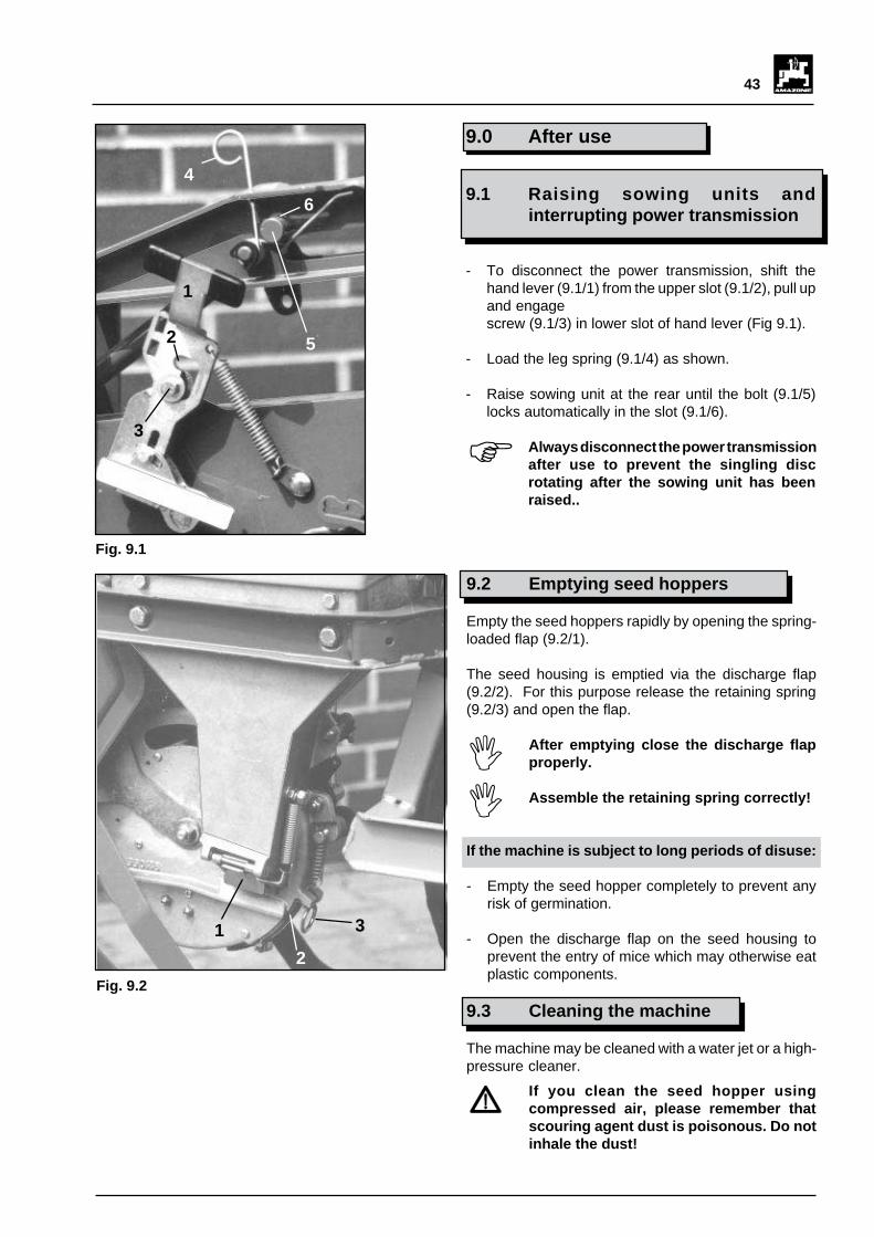
9.2 Emptying seed hoppers
Empty the seed hoppers rapidly by opening the spring-loaded flap (9.2/1).
The seed housing is emptied via the discharge flap(9.2/2). For this purpose release the retaining spring(9.2/3) and open the flap.
After emptying close the discharge flapproperly.
Assemble the retaining spring correctly!
If the machine is subject to long periods of disuse:
- Empty the seed hopper completely to prevent anyrisk of germination.
- Open the discharge flap on the seed housing toprevent the entry of mice which may otherwise eatplastic components.
9.3 Cleaning the machine
The machine may be cleaned with a water jet or a high-pressure cleaner.
If you clean the seed hopper usingcompressed air, please remember thatscouring agent dust is poisonous. Do notinhale the dust!
Fig. 9.2
1 3
2
9.0 After use
9.1 Raising sowing units andinterrupting power transmission
- To disconnect the power transmission, shift thehand lever (9.1/1) from the upper slot (9.1/2), pull upand engagescrew (9.1/3) in lower slot of hand lever (Fig 9.1).
- Load the leg spring (9.1/4) as shown.
- Raise sowing unit at the rear until the bolt (9.1/5)locks automatically in the slot (9.1/6).
Always disconnect the power transmissionafter use to prevent the singling discrotating after the sowing unit has beenraised..
F
II
44
10.0 Commissioning fertilizer drill
10.1 Filling fertilizer hopper
Before filling the fertilizer hopper connectthe seed spacing drill to the tractor.
- Open the fertilizer hopper lid (10.1/1). The cover isautomatically locked when open to prevent itslamming shut during high winds or under otherinfluences.
- Fill the fertilizer hopper from the rear.To close thefertilizer hopper lid lift the lock (10.1/2) with one handand close the lid with your free hand.
Fig. 10.1
2
1
10.2 Raise fertilizer screen
- Raise the fertilizer screen (10.2/1) with the aid of thehandles and lock in place with the locking bracket(10.2/2).
If required, when raised the fertilizer screenmay be removed from the rear.
Keep hands away from the fertilizer hopper.There is a risk of injury from the rotatingagitator shaft! Fig. 10.2
12
Fig. 10.3
21
5
4
3
67
F
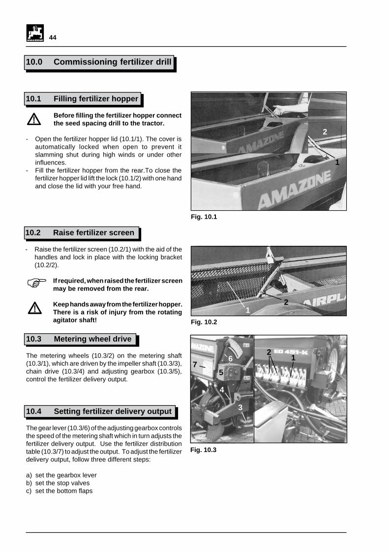
10.3 Metering wheel drive
The metering wheels (10.3/2) on the metering shaft(10.3/1), which are driven by the impeller shaft (10.3/3),chain drive (10.3/4) and adjusting gearbox (10.3/5),control the fertilizer delivery output.
10.4 Setting fertilizer delivery output
The gear lever (10.3/6) of the adjusting gearbox controlsthe speed of the metering shaft which in turn adjusts thefertilizer delivery output. Use the fertilizer distributiontable (10.3/7) to adjust the output. To adjust the fertilizerdelivery output, follow three different steps:
a) set the gearbox leverb) set the stop valvesc) set the bottom flaps

45
10.4.1 Setting gear lever
The fertilizer delivery output can be changed by adjustingthe gear lever (10.4/1). The higher the figure on thescale (10.4/2), the greater the output.
Adjust the gearbox as follows:
- Loosen the knob (10.4/3) by turning it to the left.
- Move the gear lever down (towards the highestfigure on the scale) and shift from below to therequired position as indicated in the fertilizerdistribution table.
- Tighten the knob.
The figures indicated in the fertilizerdistribution table are intended as a guideonly. Deviations may occur as a result ofseed size, type and specific weight. A truingtest is advisable in each case.
Fig. 10.4
3
1
4
2
10.4.2 Setting stop valves
The stop valves (10.5/1) may be locked in threedifferent positions:
"closed" "3/4 open" "open"
The stop valves should all occupy the "3/4 open" position.
10.4.3 Setting bottom flaps
When metering the fertilizer, the lever (10.5/2) is lockedon to the bolt (10.5/3).
To clean the machine open the bottom flaps with thelever (10.5/2).
1
Fig. 10.5
2
3
I
I

46
10.5 Truing test to check fertilizerdelivery output
During the truing test the impeller shaft (10.6/1) isrotated clockwise with the aid of the crank (10.6/2) andthe test run on the field is checked. The fertilizercollected from the individual coulters is checked againstthe required amount of fertilizer. The collected fertilizershould equate to 1/10 or 1/40 of the fertilizer delivered.
Carry out the truing test as follows:
- Set stop valve to "3/4 open".- Check whether both bottom flaps are engaged.- Set the gear lever with the aid of the fertilizer
distribution table (see Chapter 10.4).
The figures indicated in the fertilizerdistribution table apply to a seed drillworking width of 3 m and 4.5 m respectively.
- Insert the truing crank (10.6/1) and carry out aspecified number of crank turns according to thetable below taking into account the working widthand tyres.
a) Fertilizer collected from all the coulters:
- Weigh the fertilizer [kg] and multiply by factor"10" (1/10 ha) or factor "40" (1/40). The figureobtained equates to the fertilizer delivery output in[kg/ha].
b) Fertilizer collected from one coulter only:
- Close stop valves of other metering housing.- Weigh the collected fertilizer [kg] and multiply by the
number of coulters and by the factor "10" (1/10 ha)or "40" (1/40). The figure obtained equates to thefertilizer delivery output in [kg/ha].
BereifungTyresbandenpneumatiques
Kurbelumdrehungen am Rad - ArbeitsbreiteCrank turns at the wheel - working widthomwentelingen aan het wiel - werkbreedtenembre de tours de manivelle à la roue - largeur de travail
3,0 m 4,5 m 6,0 m
6.00-161/10 ha 159 -- --
1/40 ha 39,8 -- --
10.07/75-1531x15,5/15
1/10 ha 147 98 74
1/40 ha 37,8 24,5 18,5
Fig. 10.6
1
2
F

47
10.6 Setting fertilizer coulters
The fertilizer coulters (10.7/1) are mounted to thesectional bar (10.7/3) with the aid of support clamps(10.7/2). The fertilizer coulters are factory-set at adistance of 6 cm to the drill coulter of the sowing unit. Asfor the sowing units, this distance may be adjustedprogressively (see Chapter 6.4).
The depositing depth of the fertilizer may be changed bymoving the depth adjuster (10.7/4) on the fertilizercoulter. Secure the setting for the fertilizer coulter withthe aid of a socket pin (10.7/5).
Setting the depositing depth of the fertilizercoulter involves working below andbetween the raised machine. There is adanger from squeeze points for all bodyparts. Make sure that the raised machineis safely secured against accidentallowering!
If the fertilizer coulter meets any obstacles (10.7/6) inthe soil it avoids the obstacle by moving behind, aboveor around it.
Two fertilizer hoses lead to each fertilizer coulter.
Make sure that the hoses do not sag andthat the hoses do not get blocked up withfertilizer. Shorten hoses if necessary.
Only one hose leads to each outer fertilizer coulter onthe ED 451 and ED 451-K.
10.7 Fertilizer delivery to outer fertilizercoulters in ED 451 and ED 451-K
Fertilizer is delivered to the outer fertilizer coulters bymeans of compressed air. Metered fertilizer enters theinjector (10.8/1) where it is fed to the outer fertilizercoulters by the compressed air produced by thecompressed air fan (10.8/2).
6
2 1
5
4
3
Fig. 10.7
Fig. 10.8
1
2 3
I

48
10.8 Reduced working width by liftingouter sowing units on ED 451-Kwith fertilizer drill
- Lift outer sowing units. The operating mechanismfor the singling discs is switched off automatically.
- Close the stop valves (10.8/3) of the outer fertilizercoulters.
If the stop valves of the metering wheelsfor the outer fertilizer coulters are notclosed, fertilizer is spilled on to the soilsurface.
10.9 After use - emptying fertilizer hopper(for rapid fertilizer evacuation seespecial fitting)
- Place a suitable container beneath the fertilizercoulters to empty the fertilizer hopper.
- Open all the stop valves (10.9/1), release the bottomflap lever (10.9/2) and move it back and forth until thebottomflaps are fully open.
- After complete evacuation of fertilizer hopper onED 451 and ED 451-K:
- Turn on the fan briefly thereby emptying thehoses leading to the outer fertilizer coulterscompletely.
- Clean the fertilizer hopper and coulter thoroughlywith water.
Make absolutely sure that the machine isentirely free of any fertilizer or water andfertilizer mixture. If any damp fertilizer isleft behind, when it dries it may form lumpsor lead to a complete blockage next timethe machine is used causing damage torotating parts.
1
Fig. 10.9
Fig. 10.8
1
2 3
I
I

49
11.0 Servicing, repair andmaintenance
See Chapter 3.4 for servicing, repair andmaintenance.
11.1 Threaded joints
Check all threaded joints after the first 2operating hours and every 100 operatinghours subsequently. Tighten if necessary.
11.2 Cardan shaft
Lubricate with brand-name grease before handling themachine and every 8 operating hours subsequently(Fig. 11.1). After long periods of disuse, clean andlubricate the cardan shaft.
Grease the pipes in winter to preventfreezing.
11.3 Multiple ribbed belt for fan driveunit
Proper tensioning of the multiple ribbed belt (11.2/1) isessential for its service life. The elongation of the beltis determined by the performance of the tractor powertake-off shaft.
Slow coupling of the tractor power take-offshaft increases the service life of the belt.
The prescribed belt tensioning is obtainedwhen the tension spring (11.2/2) measures260-5 mm in length.
Correct belt tensioning reduces prematurewear and tear.
Tension the multiple ribbed belt as follows:
- Loosen the locknuts (11.2/3) on the tensioning bolt(11.2/4).
- Set the tension spring length to 260 mm and re-tighten locknuts.
Check the belt after the first 10 hours andat intervals of 50 operating hourssubsequently. Tighten if necessary.
Fig. 11.1
1
2
3 4
Fig. 11.2
I
F
IFI
I

50
To check multiple ribbed belt:
- Remove case (11.3/1) and check belt for any signsof wear.
Re-assemble case correctly!
11.4 Tyre pressure
Check the tyre air pressure at regularintervals.
The tyres are factory-set at the following air pressurelevels:
Tyres 6.00 - 16 1.2 bar
Tyres 10.0/75 - 15 0.8 bar
Terra tyres (special fitting) 2.5 bar
11.5 Chain drive
The chain drives on the ED 301, ED 451 and ED 451-K are fitted with roller chains.
After long periods of disuse remove rollerchains, wash in kerosene and then dip intopreheated grease or oil. Do not lubricatethe chain during operation!
Check chain drive after 10 hours ofoperation and thereafter at intervals of 100operating hours. Regulate the tension ifnecessary. If the chain cannot be tensionedany more, reduce to size.
The machines are fitted with the following threedrive chains:
1. The drive chain (11.4/1) is connected from theimpeller shaft to the gearbox input shaft on thevariable speedgear.
The chain is tensioned with the aid of a spring-loaded chain adjuster. Remove the case to checkthe chain tension.
The reinforced design of the chain and itsclosing link provide increased breakingforce. When eplacing the closing link orthe complete chain use original AMAZO-NE replacement parts only.
Fig. 11.3
1
1
1
Fig. 11.4
1
I
F
I
I

51
2. Shifting chain (11.5/1) from variable speed gear.
This chain is tensioned with the aid of the spring-loaded chain tensioning unit (11.5/2).
The reinforced design of the shifting chainand its closing link provide increasedbreaking force. When replacing the closinglink or the complete chain use originalAMAZONE replacement partsonly.
3. Drive chain (11.6/1) of the sowing unit connectingthe shaft on the gear output of the secondarytransmission (11.6/2) to the sowing shaft(hexagon shaft).
This chain is tensioned with the aid of the spring-loaded chain tensioning unit.
The reinforced design of this chain and itsclosing link provide increased breakingforce. When replacing the closing link orthe complete chain use original AMAZO-NE replacement parts only.
The AMAZONE ED 301, 451 or 451-K equipped withan additional drive chain for the fertilizer drill:
4. The drive chain (11.7/1) connects the drive wheelshaft (11.7/2) to the adjusting gear which controlsthe fertilizer delivery output.
This chain is fitted with a spring-loaded chain adjuster.To adjust the tension remove the chain case. If thechain adjuster is no longer effective, reduce thelength of the chain.
Fig. 11.5
1
2
I
Fig. 11.7
1
2
Fig. 11.6
1
2
I

52
11.6 Singling discs and vacuuming
The singling disc and the vacuum (11.8/2) in the seedhousing are produced from two differenthigh-quality plastics. The seed housing seal (11.8/3)consists of foam material.
The vacuum acts as a seal between the singling discand the suction cover (11.8/4) whilst the seed housingseal closes the singling disc securely to the seedhousing.
The singling discs, vacuum and seed housing aresubject to natural wear and tear.
According to the degree of use and operating conditions,wearing-in grooves form in the singling discs.
If the wearing-in grooves show a depth of1.5 - 2 mm, replace the singling discs as aproper seal can no longer be guaranteed.
Similarly, replace the seed housing seal (11.8/3) ifdamaged.
To ensure proper operation of the singlingcomponents, check the singling unit afterevery 50 hours of operation. See Chapter5.1.
11.7 Oil level in adjusting gear forfertilizer delivery output
Check the oil level at the oil inspection window on theadjusting gear (11.9/1). An oil change is not required.To refill, unscrew cover and use hydraulic oil WTL 16.5cSt/50°C or engine oil SAE 10 W.
Filling capacity is 1.8 l.
11.8 Replacing coulter points in sowingand fertilizer coulters
The coulter points (11.10/1 or 11.10/2) of the sowingand fertilizer coulters (11.10/3 or 11.10/4) are made ofinterchangeable chilled cast iron points.
If any signs of wear and tear appear, replace withnew chilled cast iron points:
Sowing drill coulter:
- Remove riveted joints.- Replace old points with new chilled cast iron points.- Rivet the points back on.
156
23 4
Fig. 11.10
Fig. 11.9
Fig. 11.8
1
1
2
4
3
I
I

53
Fertilizer drill coulter:
- After removing the riveted joints, turn the points backto front before replacing with new chilled cast ironpoints.
- Rivet the chilled cast iron points back on.
Check the sowing and fertilizer coulterevery 50 operating hours for wear and tear.If the points show any signs of wear andtear, either replace or turn back to front.
Replace or turn the chilled cast iron pointsback to front before the side plates (11.10/5or 11.10/6) on the sowing and fertilizercoulters show any sign of ageing.
11.9 Cleaning suction fan impeller
In certain circumstances the drawing in of scouringagents can lead to deposits on the suction fan impeller.This imbalance can lead to uneven running of the fanimpeller.
If the fan impeller starts running unevenly, switch on thefan and direct a jet of water into the suction area of thefan. This will remove any deposits from the impeller.
The water is extracted from the fan bycentrifugal force.
11.10 Servicing table
Fig. 11.10
156
23 4
I
F
Component
Servicing interval [hrs]
Firstservicing
after
Additionalservicing after
2 10 50 8 25 50 100
Threaded joints x x
Cardan shaft x
Multiple ribbed belt x x
Chain drives x x
Singling discs and foamseal
x x
Vacuum x x
Coulter points onsowing and fertilizercoulters
x x
Grease bearings ondrive shafts
x

54
12.0 Special fittings
All the parts and equipment listed under this title are notincluded as standard fittings. However they can besupplied by or ordered from AMAZONE ED and fittedsubsequently. All the assembly holes have alreadybeen provided in the basic machine.
12.1 Singling discs
30/5 green (for corn (standard)), order no 910 777
30/5.8 natural (for corn with high TKG and high speeds),order no 910 790
45/6 red (for field beans), order no 910 792
45/5 dark grey (for beans and peas), order no 910 793
45/4 orange (for soya beans), order no 910 791
45/2.5 black (for small beans), order no 910 795
30/2.5 brown (for sunflowers), order no 910 794
45/3.2 light blue (for cotton), order no 913 687
12.2 Hydraulic switch unit for trackindicator with connector, order no913 175
(in 4.50 m machines used for marking tractor wheeltrack only not tractor centre)
To activate the hydraulic switch unit (12.1/1), connectthe hydraulic cylinder (12.1/2) to the single-acting controlvalve of the tractor.
To switch the track indicator over, turn the tractor controlvalve to the "raise" position. During turning manoeuvresboth track indicators are then lifted up. After turningmanoeuvres return the control valve back to the "lower"position and the formally inactive track indicator disc willautomatically be lowered.
Squeeze point!Standing near switch unit and the trackindicators is prohibited when operatingthe switch unit. There is a risk of injuryfrom moving parts.
1
2
Fig. 12.1
44
35
6
7

55
12.2.1 Setting switch unit for track indicator
Mount the AMAZONE ED to the tractor. When themachine is disconnected, and the left track indicator islowered with the aid of the left plugboard (12.1/3).Secure the wire cable (12.1/4) with the aid of the chainon the radial arm of the track indicator so that the cableis suspended slightly as soon as the track indicator discis positioned on the wheel tread. This limits the workingdepth of the track indicator from between 60 to 80 mm.
When the automatic switch unit is activated the leftplugboard (12.1/3) swings inwards and the rightplugboard swings outwards. Fasten the right end of thechain to the right track indicator as described above.See Chapter 6.3.3.
When the seed spacing drill is raised, check to ensurethat both track indicators are lifted sufficiently high. Ifthis is not the case, adjust the chain length on the radialarm of the track indicator.
Secure the wire cable (12.1/4) to the bolt (12.1/5) on theED 451 and ED 451-K. If the track indicator discs digtoo deeply into the soil the indicators may becomedamaged.
12.2.2 Resetting hydraulic switch unit
The switch unit is factory-set to ensure trouble-freeoperation. After new machines have been run in, undercertain circumstances it may be necessary to adjust theswitch unit slightly if the switching is no longer regular orinaccurate.
Adjust the unit as follows:
- Apply pressure oil to the hydraulic cylinder (12.1/2).
- Remove locknut (12.1/6) from U-bolt.
- Turn the piston of the hydraulic cylinder with anopen-ended spanner until the leaf spring on theswitch unit audibly locks into place and there is aclearance of 1 to 2 mm between the spring and thetooth.
- Carry out a trial operation to check whether theswitch unit is properly adjusted.
- Tighten the locknut on the U-bolt of the hydrauliccylinder.
1
2
Fig. 12.1
44
35
6
7

56
12.3 Vertical, hydraulically activatedraising of track indicator,order no 913 177
To raise the track indicator connect it to two single-acting or one double-acting control valve on thetractor.
The actuator (12.2/1) has a dual purpose: to switch thetrack indicator over on the soil and to raise the trackindicator. By raising the track indicator, the largemachine width of the seed spacing drill which is causedby the wide projection of the track indicator, is reducedin size in a few moments. In this way obstacles can beeasily avoided without the need for the tractor operatorto leave the cab.
After unlocking the track indicator from its transportposition, turn the control valve on the tractor to "unload"and a track indicator will be lowered to the operatingposition. If the track indicator is on the "wrong side", turnthe control valve on the tractor to the "pressure" positionand change the track indicator position. The loweredtrack indicator is then raised and the remaining trackindicator is lowered by turning the control valve to"unload". During turning manoeuvres both trackindicators are raised. After turning, set the control valveto "unload" so that the correct track indicator isautomatically lowered.
When raised, the position of the track indicators can beadjusted with a threaded device on the hydraulic cylinder.
When lowered, the track indicator position can beadjusted with the aid of the chain on the radial arm.
12.4 Drive for power take-off 700 rpm,order no 425 400
See Chapters 4.2 and 8.7.
12.5 Drive for power take-off 540 rpm,order no 914 260
See Chapters 4.2 and 8.7.
12.6 Drive for power take-off 1000 rpm,order no 914 261 (standard)
See Chapters 4.2 and 8.7.
1
Fig. 12.2

57
Fig. 12.3
1
3
5
4
2
12.7 Drill coulter for beans,order no 401 800
(Recommended minimum depositing depth: 7 cm)
With the beans coulter seeds may be deposited at agreater depth in the seedbed. The depositing depth canbe set anywhere between 0 to 12 cm. See Chapter 8.5.
12.8 Free-running cardan shaft, orderno 135 301
See Chapter 6.2.
12.9 4 spring-mounted track looseners,order no 913 134
In addition to loosening the soil, the main purpose of thetrack looseners (12.3/1) is to cover the tractor tracks.Mount the track looseners as shown in Fig 12.3 so thatthey are positioned approximately 5 cm right and left ofthe tractor track in the loose earth to "plough" the tractortrack "closed". This is the best means of levelling thetrack.
Mount the track looseners to the frame (12.3/2) of theseed spacing drill.
The track looseners can be moved along the entirelength of the frame. The locking screw (12.3/3) preventsthe track loosener from falling off if the fastening screws(12.3/4) become loose. The latter cannot fall throughthe retaining bracket (12.3/5) which is held in place bythe locking screw.
12.10 Terra tyres 31 x 15.5/15,order no 366 800(profile XT II 792 mm Æ, 368 mm wide)
Terra tyres are particularly suitable for light soils as themachine weight is distributed over a large contact area.Recommended tyre pressure: 0.5 bar.

58
12.11 Spring pressure adjustment ofsowing units (per coulter),order no 911 546
The spring pressure adjustment of the sowing unitsproduces an additional loading or unloading effect onthe sowing units. This is specially recommended formulch seed and for deep depositing depths.
The detent lever (12.4/1) and the tension spring (12.4/2) are used for loading and unloading the sowing unitsin 2 positions.
If the detent lever is locked in position I or II (neutral), thecoulter is pressed into the soil with the dead weight ofthe sowing unit. If the dead weight of the sowing unitis insufficient to press the coulter into the soil to therequired depth, eg, in heavy soils, move the detentlever (12.4/1) to provide an additional coulter loadso that it locks into positions III or IV.
If the coulter digs too deep into the soil through thedead weight , move the spring to the bottom lug tounload the weight and lock the detent lever in positionsI or II. Use positions III and IV to make the spring neutral.
12.12 Loading platform, order no 913 408
A loading platform (12.5/1) can be mounted to the rearof the ED seed spacing drill to make filling the fertilizerhopper simpler.
The loading platform should to used to fillthe machine only. Standing on the platformwhilst the vehicle is in motion is prohibited!
12.13 Wheel stripper (set),order no 913553
1
2 IIIII
IV
I
3
Fig. 12.4
Fig. 12.5
1

59
12.14 Rear lighting, order no 431 400
The lighting system (12.6/1) can be retrofitted andconsists of a right and left lighting set, a socket outletwith flex, parking lights to DIN 11030, licence platebracket and connecting cable.
12.15 Front side lights, order no 158 301
The front side lights (12.6/2) can be retrofitted andconsist of 2 lights, right and left, parking lights to DIN11030 and a plug.
1
2
Fig. 12.6
12.16 Mulch seed fittings (per coulter),order no 913 404
For a 4 row machine, 2 right and 2 left fittings arerequired. When retrofitting, the standard coulter isexchanged for a unit consisting of a coulter, cleaningdisc (12.7/1) and coverer.
12.17 Fertilizer coulter for mulch seed
For a 4 row machine, 2 right and 2 left fittings arerequired. When retrofitting, the standard fertilizer coulteris exchanged for a unit consisting of a fertilizer coulterand cleaning disc (12.7/2).
Fertilizer coulter for mulch seed, right, order no 913 405.
Fertilizer coulter for mulch seed, right, order no 913 406.
Fig. 12.7
1
2

60
12.18 Rapid fertilizer evacuation,order no 913 535
The rapid evacuation of the fertilizer hopper is facilitatedby two hoses which are attached right and left to thebottom of the fertilizer hopper. With the aid of thesehoses any fertilizer remaining in the hopper can beeasily evacuated into a collecting basin below.
Operating procedure for evacuating fertilizer hopperfrom right and left:
- Place a sufficiently large collecting basin below theED.
- Remove the locking bolt (12.8/1) from the hoseretaining plate.
- Pull the hose out sideways out of the retaining plateand hold it directly over the collecting basin until thehopper is empty.
- To empty the fertilizer hopper completely, seeChapter 10.9.
- Push the hose back sideways onto the retainingplate.
- Insert locking bolt in retaining plate.
Fig. 12.8
1

61
12.19 ED fertilizer filling tube,order no 913 407
The filling tube is operated by means of the hydraulicmotor (12.9/1). For this purpose a double-acting controlvalve is required on the tractor. The maximum volumeof oil of 25 l/min is obtained when the power controlvalve (12.9/2) is fully open. At a volume of oil of 25 l/minthe speed of the tube is 500 rpm. The hydraulic motorspeed (tube speed) may be adjusted with the aid of thepower control valve.
The hydraulic system is fitted with non-return valves in the hydraulic lines or asingle-acting hydraulic connector (zinccoloured) for protection.
For tractors with one oil circuit only, thehydraulic motor and the three-pointhydraulic system cannot be run in parallel.Switch off the hydraulic motor to removefrom AMAZONE ED.
Tractors fitted with a constant pressurehydraulic system (eg, John Deere) are notdesigned to operate on engine oil. Followthe manufacturer's recommendations andcontact AMAZONEN-WERKE for furtherinformation.
The filling height of the hopper can beadjusted by changing the filling tubebracket near the punch profile.
The hydraulic tilting mechanism for the filling tubelowers the tube to the filling position (filling height 50 cm)and raises it into the transport position to obtain maximumground clearance during sowing operations. Thehydraulic motor and the hydraulic tilting mechanism arecoupled together.
Operating the filling tube:
- Connect the hydraulic lines to the tractor.- Open the stop valve.- Turn the control valve to "lift" - this engages the filling
tube which is lowered down to the ground.- Move backwards, eg, towards a coupling, and lower
the ED.- Fill the tube via the hopper and the in-built screen.- To ensure even distribution of the fertilizer in the
hopper move the swivel head (12.9/3) with the aid ofthe bar(12.9/4).
- Empty filling tube completely.- Move control valve to "lower" and raise the filling
tube to the transport position with the hydrauliccylinder.
- Close stop valve thereby locking the tiltingmechanism.
1
2
34
Fig. 12.9
F
F
F
F

62
H. DREYER GmbH & Co.KGPostbox 51D-49202 Hasbergen-Gaste
Tel.: (05405) 501-0Telefax: (05405) 50 11 [email protected]://www.amazone.de
Branch factories at D-27794 Hude • F 57602 ForbachSubsidiaries in Great Britain and France
Factories for: Mineral fertilzer-spreaders, field sprayers, seed drills, soil tillage machinery, storage-hallsand amenity equipment