Embed Size (px)
Citation preview

Operator's Manual
®
10 in. TABLE SAW WiTH STAND
Model No. 137.248850
CAUTION:
Before using this Table Saw,read this manual and follow
all its Safety Rules and
Operating instructions
Customer Help Line
For Technical Support
1-800,.843-1682
e Safety Instructions• Installation
o Operatione Maintenance
• Parts List
Sears Parts &
Repair Center
1-800-488-1222
Sears, Roebuck and Co., Hoffman Estates, IL 60179 USAVisit our Craftsman website: www.sears.com/craftsman
Part No. 137248850001
SECTION PAGEWarranty ................................................................ 2
Product Specifications ........................................... 2
Power Tool Safety ................................................. 3
Table Saw Safety .................................................. 4
Electrical Requirements and Safety ...................... 5
Accessories and Attachments ............................... 6
Tools Needed For Assembly ................................. 6Carton Contents .................................................... 6
SECTION PAGE
Know Your Table Saw ................................... 8
Glossary of Terms ......................................... 9
Assembly and Adjustments ........................... 10
Operation ...................................................... 17
Maintenance ................................................. 22
Troubleshooting Guide .................................. 23Parts List ....................................................... 24
Push Stick Plan............................................. 28
ONE=YEAR FULL WARRANTY ON CRAFTSMAN TOOL
if this Craftsman tool fails due to a defect in material or workmanship within one year from the date of purchase,CALL 1=800=4-MY-HOME® TO ARRANGE FOR FREE REPAIR (or replacement if repair proves impossible).tf this tool is used for commercial or rental purposes, this warranty will apply for only ninety days from the date of
purchase. This warranty applies only while this tool is in the United States.This warranty gives you specific legal rights, and you may also have other rights, which vary, from state to state.
Sears, Roebuck and Co., Hoffman Estates, IL 60179
WARNINGISome dust created by power sanding, sawing, grinding, drilling and other construction activities containschemicals known to cause cancer, birth defects or other reproductive harm. Some examples of thesechemicals are:
• Lead from lead-based paints• Crystalline silica from bricks, cement and other masonry products• Arsenic and chromium from chemically treated lumber
Your risk from these exposures varies, depending on how often you do this type of work. To reduce your
exposure to these chemicals, work in a well ventilated area and work with approved safety equipment such asdust masks that are specially designed to filter out microscopic particles.
MOTOR
Type .......................................................... Universal
Amps ......................................................... 15Voltage ...................................................... 120Hz .............................................................. 60
RPM (no load) ........................................... 5000
[A WARNINGI
SAW
Rip Capacity With Extension ........ 30 in. Right & 18 in. LeftBlade Size ................................... 10 in.Blade Arbor Size ......................... 5/8 in.
Maximum Cut Depth @ 90° ......... 3 in.Maximum Cut Depth @ 45° ......... 2-1/2 in.Maximum Diameter Dado ........... 6 in. (Stackable only)Maximum Dado Cut Width .......... 1/2 in.
To avoid electrical hazards, fire hazards or damage to the tool, use proper circuit protection.This tool is wired at the factory for 110=120 Volt operation. It must be connected to a 110=120 Volt / 15 Amperetime delay fuse or circuit breaker. To avoid shock or fire, replace power cord immediately if it is worn, cut ordamaged in any way.Before using your tool, it is critical that you read and understand these safety rules. Failure to follow theserules could result in serious injury to you or damage to the tool.

GENERAL SAFETY iNSTRUCTiONSRead and understand all the instructions below before using the power tool. These safety instructions are notmeant to cover every possible condition that could occur. As with any power tool, common sense, vigilanceand due care must be used.
1. READ and become familiar with the entire Operator' 17.s Manual. LEARN the tool's application, limitationsand possible hazards.
2. [ _k WARNING ]Look for this symbol that 18.identifies important safety precautions, it meansCAUTION! Become alert, your safety is involvedif you do notfollow the safety instructions. 19.
3. [ _' DANG ER _Look for this symbol that 20.identifies important safety precautions, it meansCAUTION! Become alert, your safety is involvedif you do not follow the safety instructions.
4. NEVER OPERATE THiS MACHINE WITHOUTTHE SAFETY GUARD iN PLACE FOR ALLTHROUGHSAWING OPERATIONS.
5. DO NOT USE iN A DANGEROUS ENVIRONMENTsuch as damp or wet locations or exposure to rain.Keep work area well lighted.
DO NOT use power tools in the presence offlammable liquids or gases.
KEEP WORK AREA CLEAN. Cluttered areas andbenches invite accidents.
6.
7.
8.
9.
KEEP CHILDREN AWAY. All visitors should bekept at a safe distance from the work area.
DO NOT FORCE THE TOOL. It will do the jobbetter and safer at the rate for which it wasdesigned.
10 USE THE RIGHT TOOL. Do not force the tool orattachment to do a job for which it is not designed.
11. WEAR PROPER APPAREL. DO NOT wear looseclothing, gloves, neckties, rings, bracelets or otherjewelry that may get caught in moving parts.Nonslip footwear is recommended. Wear protectivehair covering to contain long hair.
12. WEAR A FACE MASK OR DUST MASK. Sawing,cutting and sanding operations produce dust.
13. DISCONNECT TOOLS before servicing and whenchanging accessories such as blades, cutters, etc.
14. REDUCE THE RiSK OF UNiNTENTiONALSTARTING. Make sure the switch is in the OFFposition before plugging into the power supply.
15. USE ONLY RECOMMENDED ACCESSORIES.Consult the Operator's Manual for recommendedaccessories. The use of improper accessories maycause injury to you or damage to the tool. adjustingwrenches are removed from the tool before turningON.
16. REMOVE ADJUSTING KEYS AND WRENCHES.Form the habit of checking to see that keys andadjusting wrenches are removed from the toolbefore turning ON.
NEVER LEAVE TOOL RUNNING UNATTENDED.TURN THE POWER "OFF". Do not leave the toolbefore it comes to a complete stop.
NEVER STAND ON TOOL. Serious injury couldoccur if the tool is tipped or if the cutting tool isunintentionally contacted.
DO NOT OVERREACH. Keep proper footing andbalance at all times.
MAiNTAiN TOOLS WiTH CARE. Keep tools sharpand clean for most efficient and safest performance.Follow instructions for lubricating and changingaccessories.
21. CHECK FOR DAMAGED OR LOOSE PARTS.Before further use of the tool, a guard or otherpart that is damaged should be carefully checkedto ensure it will operate properly and perform itsintended function. Check for alignment of movingparts, binding of moving parts, loose mountingand any other conditions that may affect its safeoperation. A guard or other part that is loose ordamaged should be properly adjusted repaired orreplaced.
22. MAKE WORKSHOP CHILD PROOF with padlocks,master switches or by removing starter keys.
23. DO NOT operate the tool if you are under theinfluence of any drugs, alcohol or medication thatcould impair your ability to use the tool safely.
24. USE A DUST COLLECTION SYSTEM whereverpossible. Dust generated from certain materials canbe hazardous to your health and in some cases, afire hazard. Always operate the power tool in a wellventilated area with adequate dust removal.
25. ALWAYS WEAR EYE PROTECTION. Any powertool can throw foreign objects into your eyes whichcould cause permanent eye damage. ALWAYSwear safety goggles (not glasses) that comply withANSI safety standard Z87.1. Everyday glasseshave only impact resistant lenses. They ARE NOTsafety glasses. NOTE: Glasses or goggles not incompliance with ANSI Z87.1 could cause seriousinjury when they break.
26. DiRECTiON OF FEED. Feed work into a blade orcutter against the direction of rotation of the blade orcutter only.
27. DO NOT AUTHORZE ADDiTiONAL USERS tooperate this power tool without the accompanyingoperators manual for which the user must read andunderstand.
2.
3.
4.
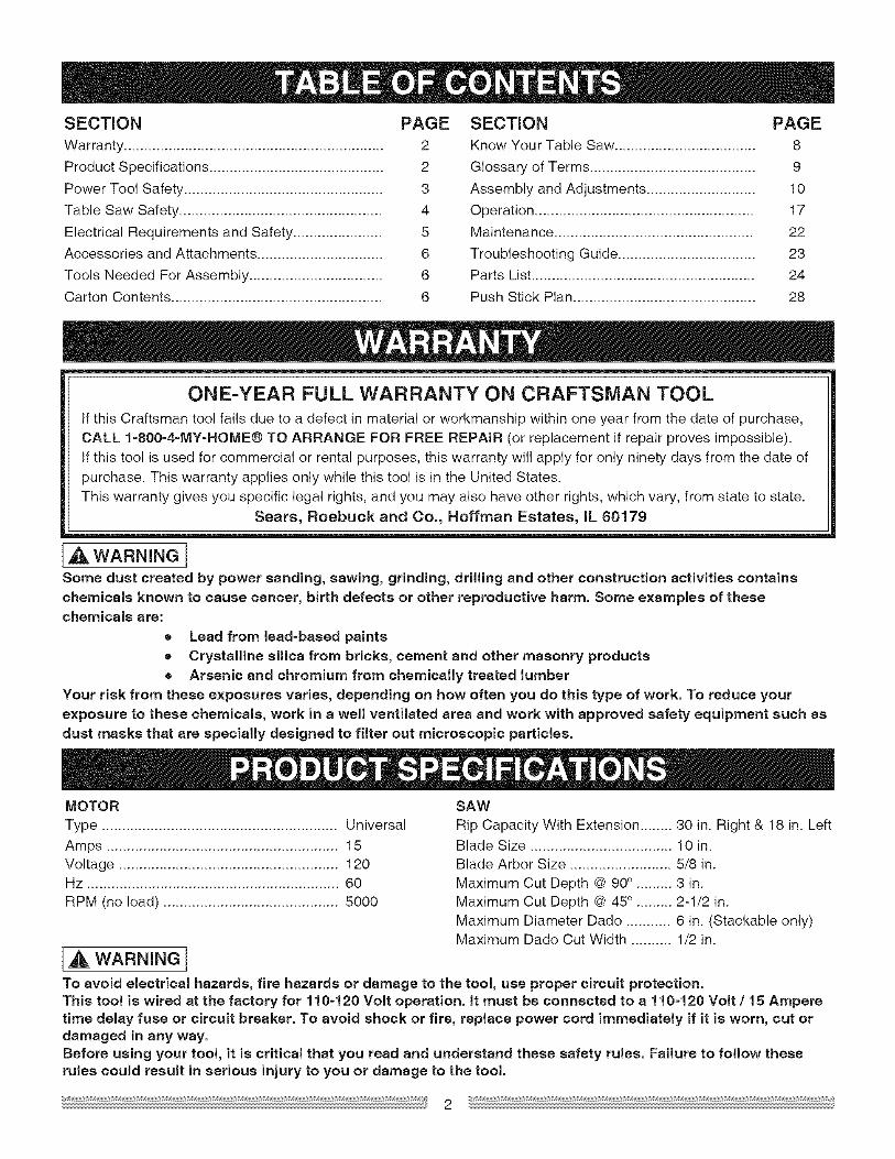
ALWAYS USE SAW BLADE GUARD, splitterand anti-kickback pawls for every through-sawingoperation. Through-sawing operations are thosein which the blade cuts completely through theworkpiece when ripping or crosscutting. Always besure blade guard is tightened securely.
ALWAYS HOLD WORK FIRMLY against the mitergauge or rip fence.
ALWAYS USE a push stick, especially when rippingnarrow stock. Refer to ripping instructions in thisOperator's Manual where the push stick is coveredin detail. A pattern for making your own push stick isincluded on page 28.
NEVER PERFORM ANY OPERATION
FREEHAND, which means using only your handsto support or guide the workpiece. Always useeither the fence or the miter gauge to positionand guide the work,
I,_k DANGER]FREEHAND CUTTING iS THE MAJOR CAUSE OFKICKBACK AND FINGER/HAND AMPUTATIONS,NEVER USE THE MITER GAUGE AND FENCESIMULTANEOUSLY,
12. PROVIDE ADEQUATE SUPPORT to the rear
and the sides of the saw table for long or wideworkpieces.
13. AVOID KICKBACKS (work thrown back towardsyou) by keeping the blade sharp, the rip fenceparallel to the saw blade and by keeping the splitter,
anti-kickback pawls and guards in place, alignedand functioning. Do not release work before passingit completely beyond the saw blade. Do not rip work
that is twisted, warped or does not have a straightedge to guide it along the fence. Do not attempt toreverse out of a cut with the blade running.
14. AVOID AWKWARD OPERATIONS and hand
positions where a sudden slip could cause yourhand to move into the saw blade.
15. NEVER USE SOLVENTS to clean plastic parts.Solvents could possibly dissolve or otherwisedamage the material. Only a soft damp cloth should
be used to clean plastic parts.
16. MOUNT your table saw on a bench or stand
before performing any cutting operations. Refer toASSEMBLY on page 10.
5. NEVER STAND or have any part of your body in 17.line with the path of the saw blade. Keep your handsout of the saw blade path.
18.
6. NEVER REACH behind or over the cutting tool for
any reason.
7. REMOVE the rip fence when crosscutting.19.
8. DO NOT USE a molding head with this saw.
9. FEED WORK INTO THE BLADE against thedirection of rotation only. 20.
10. NEVER use the rip fence as a cut-off gauge whencrosscutting.
11. NEVER ATTEMPT TO FREE A STALLED SAW
BLADE without first turning the saw OFF. Turnpower switch OFF immediately to prevent motordamage.
NEVER CUT METALS or materials that may makehazardous dust.
ALWAYS USE IN A WELL=VENTILATED AREA.
Remove sawdust frequently. Clean out sawdustfrom the interior of the saw to prevent a potential firehazard.
NEVER LEAVE THE SAW RUNNINGUNATTENDED. Do not leave the saw until the
blade comes to a complete stop.
FOR PROPER OPERATION follow the instructions
in this Operator's Manual entitled OPERATION(Page 17).
NOTE: On machines with no stand or if stand is not
being used, a hole approximately 11 in. square mustbe cut under saw to allow sawdust to fall through.Failure to cut this hole will allow sawdust to build
up in the motor area, resulting in a fire hazard andpotential motor damage.
GROUNDING iNSTRUCTiONS
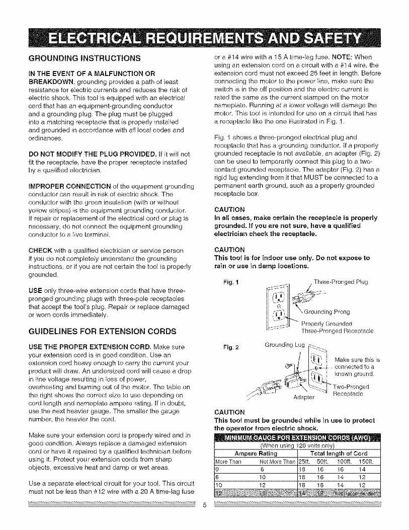
IN THE EVENT OF A MALFUNCTION ORBREAKDOWN, grounding provides a path of leastresistance for electric currents and reduces the risk ofelectric shock. This tool is equipped with an electricalcord that has an equipment-grounding conductorand a grounding plug. The plug must be pluggedinto a matching receptacle that is properly installedand grounded in accordance with all local codes andordinances.
DO NOT MODIFY THE PLUG PROVIDED. tf it will notfit the receptacle, have the proper receptacle installedby a qualified electrician.
IMPROPER CONNECTION of the equipment groundingconductor can result in risk of electric shock. Theconductor with the green insulation (with or withoutyellow stripes) is the equipment grounding conductor.tf repair or replacement of the electrical cord or plug isnecessary, do not connect the equipment groundingconductor to a live terminal.
or a #14 wire with a 15 A time-lag fuse. NOTE: Whenusing an extension cord on a circuit with a #14 wire, theextension cord must not exceed 25 feet in length. Beforeconnecting the motor to the power line, make sure theswitch is in the off position and the electric current israted the same as the current stamped on the motornameplate. Running at a lower voltage will damage themotor. This tool is intended for use on a circuit that hasa receptacle like the one illustrated in Fig. 1.
Fig. 1 shows a three-pronged electrical plug andreceptacle that has a grounding conductor. If a properlygrounded receptacle is not available, an adapter (Fig. 2)can be used to temporarily connect this plug to a two-contact grounded receptacle. The adapter (Fig. 2) has arigid lug extending from it that MUST be connected to apermanent earth ground, such as a properly groundedreceptacle box.
CAUTIONIn all cases, make certain the receptacle is properlygrounded, if you are not sure, have a qualifiedelectrician check the receptacle.
CHECK with a qualified electrician or service personif you do not completely understand the groundinginstructions, or if you are not certain the tool is properlygrounded.
USE only three-wire extension cords that have three-pronged grounding plugs with three-pole receptaclesthat accept the tool's plug. Repair or replace damagedor worn cords immediately.
GUIDELINES FOR EXTENSION CORDS
CAUTION
This tool is for indoor use only. Do not expose torain or use in damp locations.
Fig. 1 Three-Pronged Plug
q7
{__.. g Prong_1_1) Properly Grounded
Three-Pronged Receptacle
USE THE PROPER EXTENSION CORD. Make sureyour extension cord is in good condition. Use anextension cord heavy enough to carry the current yourproduct will draw. An undersized cord will cause a dropin line voltage resulting in loss of power,overheating and burning out of the motor. The table onthe right shows the correct size to use depending oncord length and nameplate ampere rating, tf in doubt,use the next heavier gauge. The smaller the gaugenumber, the heavier the cord.
Make sure your extension cord is properly wired and ingood condition. Always replace a damaged extensioncord or have it repaired by a qualified technician beforeusing it. Protect your extension cords from sharpobjects, excessive heat and damp or wet areas.
Use a separate electrical circuit for your tool. This circuitmust not be less than #12 wire with a 20 A time-lag fuse
Fig. 2 Grounding Lug _-#......
/ I_! Make sure this isI_ ._-_ connected to a
_- [ _.._,_I known ground.- _,_.L_ _ _ Two-Pronged
_}4_ J Adapter -'-_ Receptacle
CAUTION
This tool must be grounded while in use to protectthe operator from electric shock.
' O" • O'm '
(When using 120volts only)Ampere Rating Total length of Cord
MoreThan NotMoreThan 25ft. 50ft. 100ft. 150ft.0 6 8 16 16 14
6 10 8 I6 14 1210 12 6 16 14 12
RECOMMENDED ACCESSORIES
WARNINGIVisit your Sears Hardware Department or see theCraftsman Power and Hand Tools Catalog to purchaserecommended accessories for this power tool.
[A WARNINGITo avoid the risk of personal injury:• Do not use adjustable (wobble) type dadoes or
carbide tipped dado blades.= Only use atackable dadoes.• Maximum dado width is 1/2".
• Do not use a dado with a diameter larger than 6".• Do not use molding head set with this saw.• Do not modify this power tool or use accessories
not recommended by Sears.
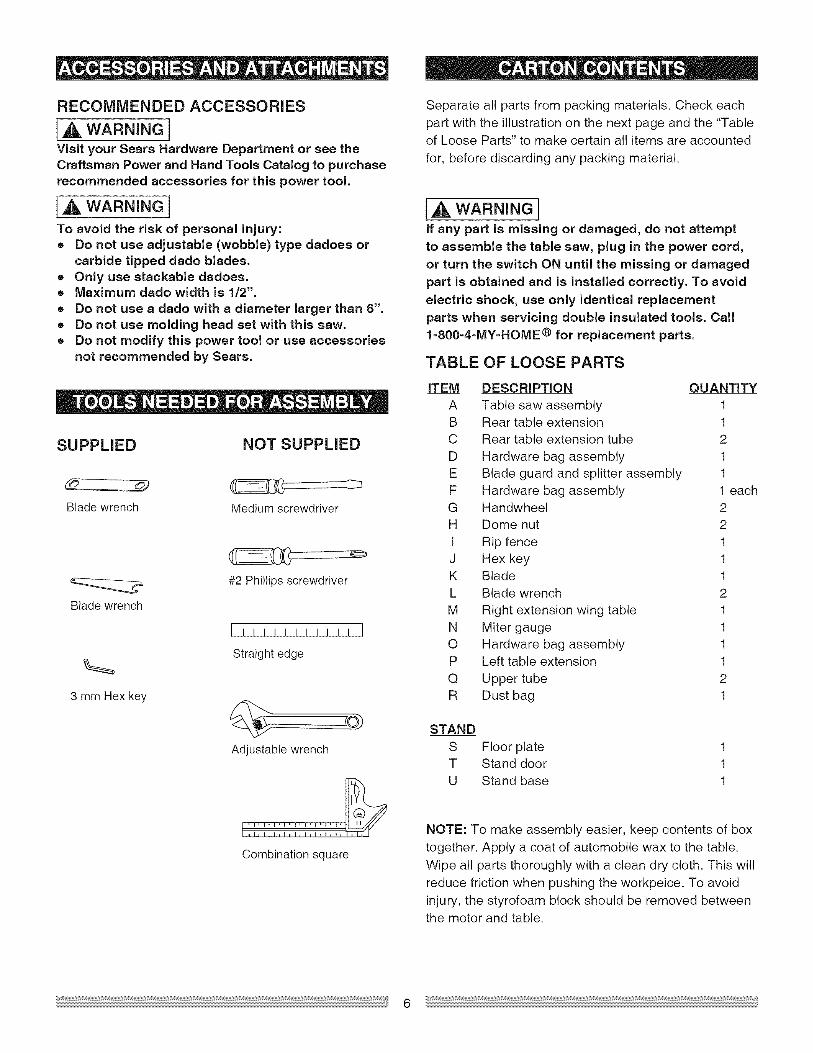
SUPPLIED NOT SUPPLIED
Blade wrench Medium screwdriver
Blade wrench
3 mm Hex key
#2 Phillips screwdriver
[ II II II III II I
Straight edge
Adjustable wrench
Combination square
Separate all parts from packing materials. Check eachpart with the illustration on the next page and the "Tableof Loose Parts" to make certain all items are accounted
for, before discarding any packing material.
IA WARNINGIif any part is missing or damaged, do not attemptto assemble the table saw, plug in the power cord,or turn the switch ON until the missing or damaged
pert is obtained and is installed correctly. To avoidelectric shock, use only identical replacementparts when servicing double insulated tools. Call1=800=4-MY=HOME® for replacement parts.
TABLE OF LOOSE PARTS
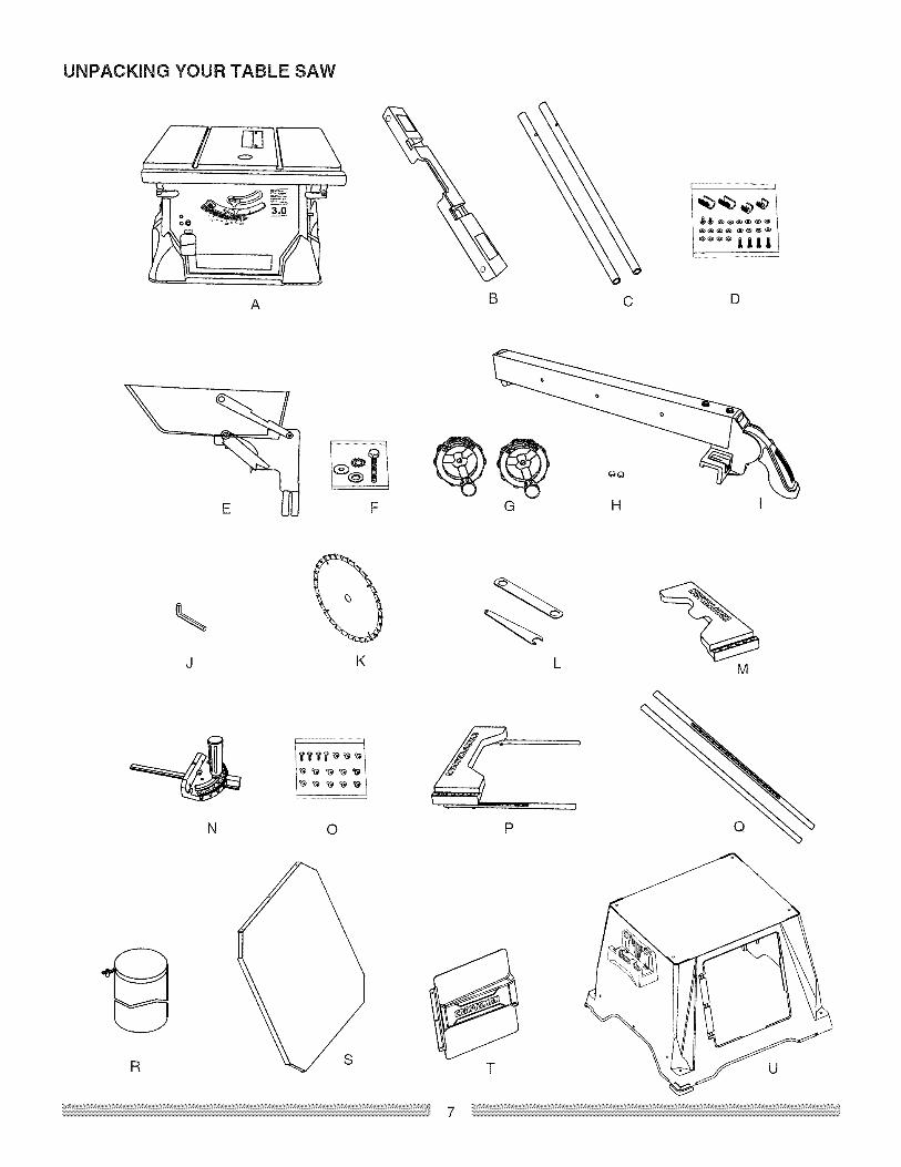
ITEM DESCRIPTION QUANTITYA Table saw assembly 1B Rear table extension 1C Rear table extension tube 2
D Hardware bag assembly 1E Blade guard and splitter assembly 1F Hardware bag assembly 1 eachG Handwheel 2H Dome nut 2
t Rip fence 1J Hex key 1K Blade 1L Blade wrench 2
M Right extension wing table 1N Miter gauge 1O Hardware bag assembly 1P Left table extension 1
Q Upper tube 2R Dust bag 1
STAND
S Floor plateT Stand doorU Stand base
111
NOTE: To make assembly easier, keep contents of box
together. Apply a coat of automobile wax to the table.Wipe all parts thoroughly with a clean dry cloth. This will
reduce friction when pushing the workpeice. To avoidinjury, the styrofoam block should be removed betweenthe motor and table.
UNPACKING YOUR TABLE SAW
A CB
l .... J,Jl_ 1
D
\J K L M
N 0 P
R T
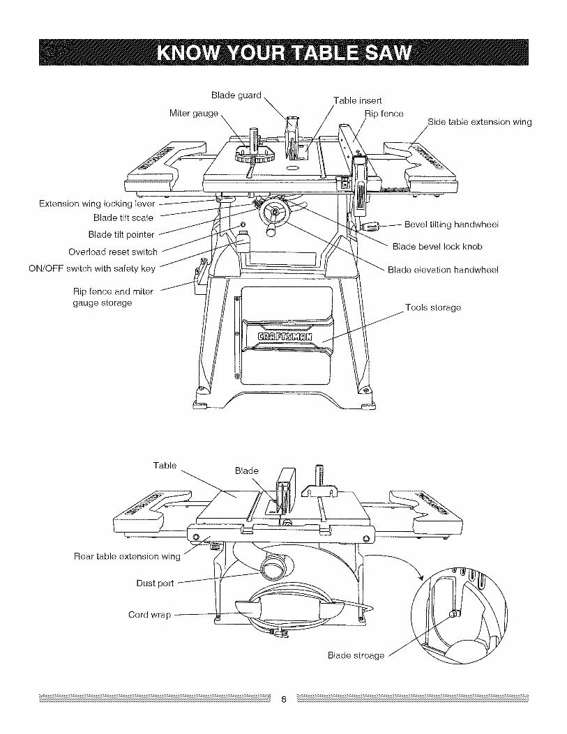
Bladeguard Tableinsert
MitergaugeX fence Sidetableextensionwing
ExtensionwinglockingleverBladetiltscale
BladetiltpointerOverloadresetswitch
ON/OFFswitchwithsafetykey
Ripfenceandmitergaugestorage
Beveltiltinghandwheel
Bladebevellockknob
Bladeelevationhandwheel
Toolsstorage
ANTFKICKBACKPAWLS- Preventstheworkpiecefrombeingkickedupwardorbacktowardthefrontof thetablesawbythespinningblade.
OVERLOADRESETSWITCH- Resetsthethermocoupleandprovidesa wayto restartthesawmotorif it overloadsoroverheats.
ARBOR- Theshaftonwhichthebladeordadoismounted.
PUSHSTICK- Usedtopushworkpieceswhenperformingrippingoperations.
BEVELCUT- Ananglecutmadethroughthefaceoftheworkpiece.
BLADEBEVELSCALE- Measurestheanglethebladeis tiltedwhensetfora bevelcut.
BLADEELEVATIONHANDWHEEL- Raisesandlowerstheblade.
BLADEGUARD- Clearplasticcoverthatpositionsitselfoverthebladewhilecutting.
COMPOUNDCUT- Asimultaneousbevelandmitercut.
RESIN- A stickysapthathashardened.
REVOLUTIONSPERMINUTE(RPM)- Thenumberofturnscompletedbyaspinningobjectinoneminute.
RiPFENCE- A guideusedforripcuttingwhichallowstheworkpiecetocutstraight.
RiPPiNG- Cutting with the grain of the wood or alongthe length of the workpiece.
SAW BLADE PATH - The area of the workpiece ortable top directly in line with the travel of the blade or thepart of the workpiece that will be cut.
CROSSCUT - A cut made across the width of the
workpiece.
DADO - Special cutting blades that are used to cutgrooves in a workpiece.
FREEHAND - Performing a cut without using a ripfence, miter gauge, hold down or other proper device toprevent the workpiece from twisting during the cuttingoperation.
SET - The distance between two saw blade tips, bentoutward in opposite directions to each other. The furtherapart the tips are, the greater the set.
SPLITTER - Keeps the workpiece split apart after beingcut to prevent binding on the blade and workpiece.
TABLE iNSERT - Insert that is removed from the tableto install / remove blades, tt is also removed for dadocutting. When dado cutting, a dado insert plate must beused.
GUM - A sticky sap from wood products.
HEEL - Misalignment of the blade.
JAMB NUT - Nut used to lock another nut in place on athreaded rod or bolt.
KERF - The amount of material removed by the bladecut.
THROUGH SAWING - Making a cut completelythrough the length or width of a workpiece.
WORKPIECE - Material to be cut.
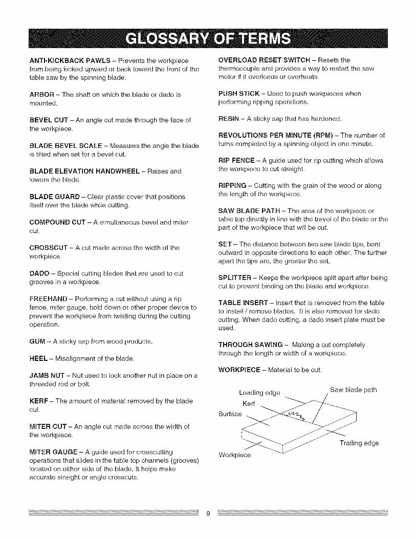
Leading edge
Kerf
Surface
Saw blade path
MITER CUT - An angle cut made across the width ofthe workpiece.
MITER GAUGE - A guide used for crosscuttingoperations that slides in the table top channels (grooves)located on either side of the blade, it helps makeaccurate straight or angle crosscuts.
Workpiece
Trailing edge
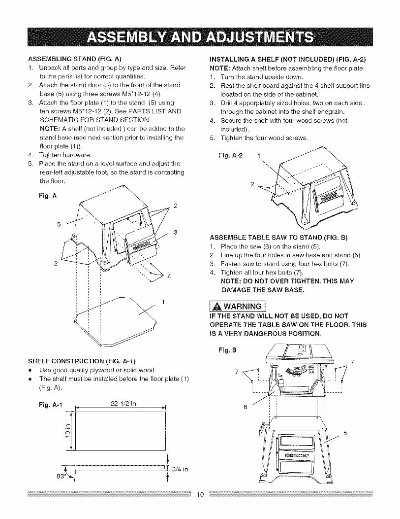
ASSEMBUNGSTAND(FIG.A)1. Unpackallpartsandgroupbytypeandsize.Refer
tothepartslistforcorrectquantities.2. Attachthestanddoor(3)tothefrontofthestand
base(5)usingthreescrewsM5"12-12(4).3. Attachthefloorplate(1)tothestand(5)using
tenscrewsM5"12-12(2).SeePARTSLISTANDSCHEMATICFORSTANDSECTION.NOTE:Ashelf(notincluded) canbeaddedtothestandbase(seenextsectionpriorto installingthefloorplate(1)).
4. Tightenhardware.5. Placethestandona levelsurfaceandadjustthe
rear-leftadjustablefoot,sothestandiscontactingthefloor.
Fig.A
INSTALUNG A SHELF (NOT iNCLUDED) (FIG. A-2)
NOTE: Attach shelf before assembling the floor plate.1. Turn the stand upside down.2. Rest the shelf board against the 4 shelf support fins
located on the side of the cabinet.
3. Drill 4 apporpiately sized holes, two on each side,through the cabinet into the shelf endgrain.
4. Secure the shelf with four wood screws (notincluded).
5. Tighten the four wood screws.
Fig. A-2 1
SHELF CONSTRUCTION (FIG. A-l)• Use good quality plywood or solid wood
• The shelf must be installed before the floor plate (1)(Fig. A).
Fig. A-1 p, 22-1/2 in ,_J
83" / ,I3/4t
ASSEMBLE TABLE SAW TO STAND (FIG. B)
1. Place the saw (6) on the stand (5).2. Line up the four holes in saw base and stand (5).3. Fasten saw to stand using four hex bolts (7).
4. Tighten all four hex bolts (7).NOTE: DO NOT OVER TIGHTEN. THiS MAY
DAMAGE THE SAW BASE.
I ,WARNINGIIF THE STAND WILL NOT BE USED, DO NOTOPERATE THE TABLE SAW ON THE FLOOR. THiSIS A VERY DANGEROUS POSiTiON.
Fig. B
MOUNTSAWONWORKSURFACE1. tf thestandwillnotbeused,thesawmustbe
properlysecuredtoasturdyworkbenchusingthefourmountingholesat thebaseofthesaw.
2. Squarethesawonthemountingsurfaceandmarkthelocationofthefour3/8in.mountingholes.
3. Drillthefour3/8in.holesintothemountingsurface.4. Placethesawontheworksurface,andalignthe
mountingholesofthesawwiththosedrilledthroughthesurface.
5. Fastenthesawtotheworksurface.Usinghardwaresuchas1/2in.lugboltswithwasher.
[A WAR"ING1Do not operate this machine on the floor. This isvery dangerous and may cause serious injury.
[A WARNINGIAlways keep your work area clean, uncluttered andwell lit.
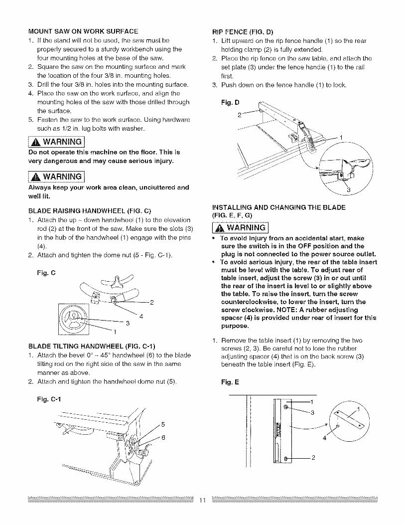
BLADE RAISING HANDWHEEL (FIG. C)1. Attach the up - down handwheel (1) to the elevation
rod (2) at the front of the saw. Make sure the slots (3)in the hub of the handwheel (1) engage with the pins(4).
2. Attach and tighten the dome nut (5 - Fig. C-1).
Fig. C
1
BLADE TILTING HANDWHEEL (FIG. C=f)1. Attach the bevel 0° - 45° handwheel (6) to the blade
tilting rod on the right side of the saw in the samemanner as above.
2. Attach and tighten the handwheel dome nut (5).
Fig. C=1
{
//
RIP FENCE (FIG. D)1. Lift upward on the rip fence handle (1) so the rear
holding clamp (2) is fully extended.2. Place the rip fence on the saw table, and attach the
set plate (3) under the fence handle (1) to the railfirst.
3. Push down on the fence handle (1) to lock.
Fig. D
INSTALLING AND CHANGING THE BLADE
(FIG. E, F, G)
I,_ WARNING I* To avoid injury from an accidental start, make
sure the switch is in the OFF position and theplug is not connected to the power source outlet.
,, To avoid serious injury, the rear of the table insertmust be level with the table. To adjust rear oftable insert, adjust the screw (3) in or out untilthe rear of the insert is level to or slightly abovethe table. To raise the insert, turn the screwcounterclockwise, to lower the insert, turn thescrew clockwise. NOTE: A rubber adjustingspacer (4) is provided under rear of insert for thispurpose.
1. Remove the table insert (1) by removing the twoscrews (2, 3). Be careful not to lose the rubberadjusting spacer (4) that is on the back screw (3)beneath the table insert (Fig. E).
Fig. E
_ _======t
_3
8---2
11
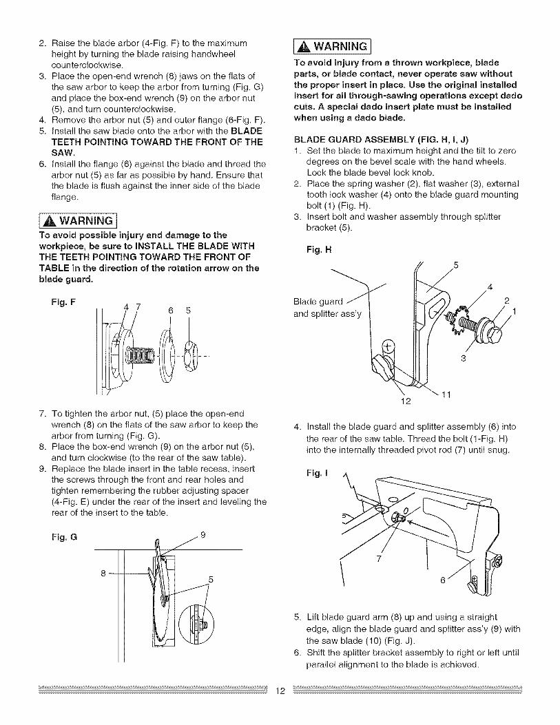
2. Raisethebladearbor(4-Fig.F)tothemaximumheightbyturningthebladeraisinghandwheelcounterclockwise.
3. Placetheopen-endwrench(8)jawsontheflatsofthesawarborto keepthearborfromturning(Fig.G)andplacethebox-endwrench(9)on thearbornut(5),andturncounterclockwise.
4. Removethearbornut(5)andouterflange(6-Fig.F).5. InstallthesawbladeontothearborwiththeBLADE
TEETHPOINTINGTOWARDTHEFRONTOFTHESAW.
6. Installtheflange(6)againstthebladeandthreadthearbornut(5)asfaraspossiblebyhand.Ensurethatthebladeis flushagainsttheinnersideof thebladeflange.
[A WARNINGITo avoid possible injury and damage to theworkpiece, be sure to iNSTALL THE BLADE WiTHTHE TEETH POiNTiNG TOWARD THE FRONT OFTABLE in the direction of the rotation arrow on the
blade guard.
Fig. F 4 7 6 5
7. To tighten the arbor nut, (5) place the open-endwrench (8) on the flats of the saw arbor to keep thearbor from turning (Fig. G).
8. Place the box-end wrench (9) on the arbor nut (5),and turn clockwise (to the rear of the saw table).
9. Replace the blade insert in the table recess, insertthe screws through the front and rear holes andtighten remembering the rubber adjusting spacer(4-Fig. E) under the rear of the insert and leveling therear of the insert to the table.
Fig. G
8 --
IA WARNING!To avoid injury from a thrown workpiece, bladeparts, or blade contact, never operate saw withoutthe proper insert in place. Use the original installedinsert for all through=sawing operations except dadocuts. A special dado insert plate must be installedwhen using a dado blade.
BLADE GUARD ASSEMBLY (FIG. H, I, J)1. Set the blade to maximum height and the tilt to zero
degrees on the bevel scale with the hand wheels.Lock the blade bevel lock knob.
2. Place the spring washer (2), flat washer (3), externaltooth lock washer (4) onto the blade guard mountingbolt (1) (Fig. H).
3. Insert bolt and washer assembly through splitterbracket (5).
Fig. H
Blade guard _
and splitter ass'y
J
12
5 4
1
4. Install the blade guard and splitter assembly (6) intothe rear of the saw table. Thread the bolt (1-Fig. H)into the internally threaded pivot rod (7) until snug.
Fig. I
5. Lift blade guard arm (8) up and using a straightedge, align the blade guard and splitter ass'y (9) withthe saw blade (10) (Fig. J).
6. Shift the splitter bracket assembly to right or left untilparallel alignment to the blade is achieved.
12
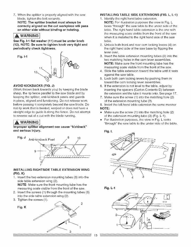
7. Whenthesplitterisproperlyalignedwiththesawblade,tightentheboltsecurely.NOTE:The splitter bracket must always becorrectly aligned so the cut workpiece will passon either side without binding or twisting,
[A WARNINaISee Fig. I-1 flat washer (11) must be under knob(12). NOTE: Be sure to tighten knob very tight andperiodically check tightness.
Fig, I-1
AVOID KICKBACKS (FIG. J)(Work thrown back towards you) by keeping the bladesharp, the rip fence parallel to the saw blade and bykeeping the splitter, anti-kickback pawls and guardsin place, aligned and functioning. Do not release workbefore passing it completely beyond the saw blade. Donot rip work that is twisted, warped or does not have astraight edge to guide it along the fence. Do not attemptto reverse out of a cut with the blade running.
[,A WARNING IImproper splitter alignment can cause "kickback"and serious injury.
Fig, J 8 10Anti-kickback Pawl
INSTALLING RIGHTSIDE TABLE EXTENSION WING(FIG. K)1. Insert the two extension mounting tubes (3) into the
side table extension wing (2).NOTE: Make sure the front mounting tube has themeasuring scale visible from the front of the saw.
2. Insert the screws (1) through the mounting tubes (3)into the side table extension wing (2).
3. Tighten the screws (1).
Fig. K z_ 2
313
INSTALLING TABLE SIDE EXTENSIONS (FIG. L, L=I)1. Identify the right hand table extension.
NOTE: For illustration purposes the view in Fig. Llooks "through" the saw table to the under side of thetable. The right hand table extension is the one withthe measuring scale visible from the front of the sawwhen it is installed to the right hand side of the sawtable.
2. Unlock both front and rear cam locking levers (4) onthe right hand side of the saw base by flipping thelever over.
3. Insert the table extension mounting tubes (2) into thetwo matching holes in the cam lever assemblies.NOTE: Make sure the front mounting tube has themeasuring scale visible from the front of the saw.
4. Slide the table extension toward the table until it restsagainst the saw table.
5. Lock both cam locking levers by pushing them intoward the cam locking lever assemblies.
6. tf the extension is not level to the table, adjust byinserting the spacers (Carton Contents D) betweenthe extension and the tube it mounts onto. See page 17.
7. Make sure the screw (1) into the matching hole (2)of the extension mounting tube (3).
8. Install the left hand table extension the same mannerNOTE:• Make sure the screw (1) into the matching hole (2)
of the extension mounting tube (3) (Fig. L-1).• For illustration purposes, the view in Fig. L looks
"through" the saw table to the under side of the table.
Fig, L
2 \1 4 3
Fig. L=I
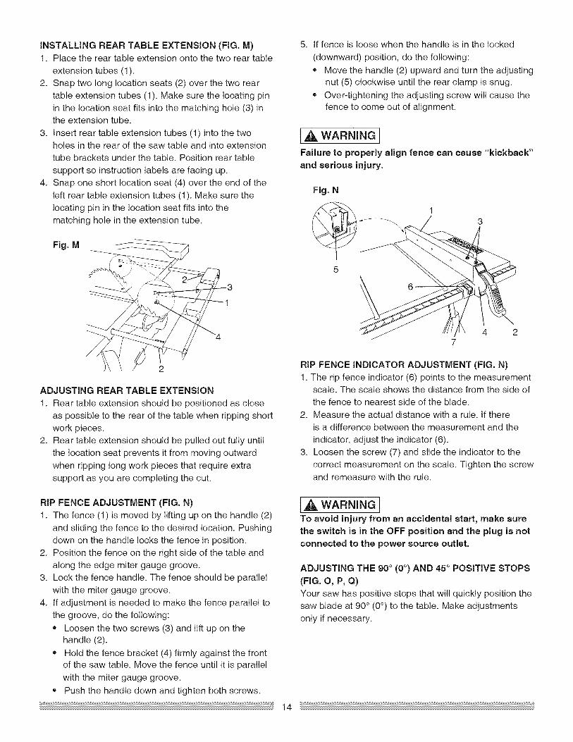
INSTALLING REAR TABLE EXTENSION (FIG, M)1. Place the rear table extension onto the two rear table
extension tubes (1).2. Snap two long location seats (2) over the two rear
table extension tubes (1). Make sure the locating pinin the location seat fits into the matching hole (3) inthe extension tube.
3. Insert rear table extension tubes (1) into the twoholes in the rear of the saw table and into extension
tube brackets under the table. Position rear table
support so instruction labels are facing up.
4. Snap one short location seat (4) over the end of theleft rear table extension tubes (1). Make sure thelocating pin in the location seat fits into the
matching hole in the extension tube.
Fig. M
ADJUSTING REAR TABLE EXTENSION
1. Rear table extension should be positioned as closeas possible to the rear of the table when ripping shortwork pieces.
2. Rear table extension should be pulled out fully untilthe location seat prevents it from moving outwardwhen ripping long work pieces that require extra
support as you are completing the cut.
RIP FENCE ADJUSTMENT (FIG. N)1. The fence (1) is moved by lifting up on the handle (2)
and sliding the fence to the desired location. Pushingdown on the handle locks the fence in position.
2. Position the fence on the right side of the table and
along the edge miter gauge groove.3. Lock the fence handle. The fence should be parallel
with the miter gauge groove.
4. tf adjustment is needed to make the fence parallel tothe groove, do the following:
= Loosen the two screws (3) and lift up on thehandle (2).
= Hold the fence bracket (4) firmly against the frontof the saw table. Move the fence until it is parallel
with the miter gauge groove.
• Push the handle down and tighten both screws.
5. tf fence is loose when the handle is in the locked
(downward) position, do the following:
= Move the handle (2) upward and turn the adjustingnut (5) clockwise until the rear clamp is snug.
= Over-tightening the adjusting screw will cause thefence to come out of alignment.
],_ WARNING I
Failure to properly align fence can cause "kickback"and serious injury.
Fig, N
5
4 27
RIP FENCE INDICATOR ADJUSTMENT (FIG. N)1. The rip fence indicator (6) points to the measurement
scale. The scale shows the distance from the side ofthe fence to nearest side of the blade.
2. Measure the actual distance with a rule. tf thereis a difference between the measurement and the
indicator, adjust the indicator (6).3. Loosen the screw (7) and slide the indicator to the
correct measurement on the scale. Tighten the screwand remeasure with the rule.
]A WARNING!To avoid injury from an accidental start, make surethe switch is in the OFF position and the plug is not
connected to the power source outlet.
ADJUSTING THE 90 ° (0°) AND 45° POSITIVE STOPS
(FIG. O, P, Q)Your saw has positive stops that will quickly position thesaw blade at 90° (0°) to the table. Make adjustmentsonly if necessary.
14
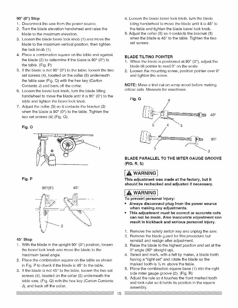
90°(0°) Stop1. Disconnectthesawfromthepowersource.2. Turnthebladeelevationhandwheelandraisethe
bladetothemaximumelevation.3. Loosenthebladebevellockknob(1)andmovethe
bladetothemaximumverticalposition,thentightenthelockknob(1).
4. Placeacombinationsquareonthetableandagainsttheblade(2)todetermineif thebladeis90° (0°) tothetable.(Fig.P)
5. tf thebladeisnot90°(0°) tothetable,loosenthetwosetscrews(4),locatedon thecollar(5)underneaththetablesaw(Fig.Q)withthehexkey(CartonContentsJ)andbackoffthecollar.
6. Loosenthebevellockknob,turnthebladetiltinghandwheelto movethebladeuntilit is90° (0°) tothetableandtightenthebevellockknob.
7. Adjustthecollar(5)so itcontactsthebracket(3)whenthebladeis90° (0°) tothetable.Tightenthetwosetscrews(4)(Fig.Q).
Fig.O
Fig.P
900(00) 450
45° Stop1. Withthebladeintheupright90° (0°)position,loosen
thebevellockknobandmovethebladetothemaximumbevelangle.
2. PlacethecombinationsquareonthetableasshowninFig.Ptocheckif thebladeis45° tothetable.
3. tf thebladeisnot45°tothetable,loosenthetwosetscrews(4),locatedonthecollar(5)underneaththetablesaw,(Fig.Q)withthehexkey(CartonContentsJ),andbackoffthecollar.
15
4. Loosenthebladebevellockknob,turnthebladetiltinghandwheeltomovethebladeuntilit is45° tothetableandtightenthebladebevellockknob.
5.Adjustthecollar(5)so itcontactsthebracket(3)whenthebladeis45° tothetable.Tightenthetwosetscrews.
BLADETiLTiNGPOINTER1. Whenthebladeispositionedat90°(0°),adjustthe
bladetiltpointerto read0° onthescale.2. Loosenthemountingscrew,positionpointerover0°
andtightenthescrew.
NOTE:Makeatrialcutonscrapwoodbeforemakingcriticalcuts.Measureforexactness.
Fig.Q 4
450
90o
3
BLADEPARALLELTOTHEMITERGAUGEGROOVE(FIG.R,S)
IA WARNING!This adjustment was made at the factory, but itshould be rechecked and adjusted if necessary.
],A WARNING]To prevent personal injury:= Always disconnect plug from the power source
when making any adjustments.• This adjustment must be correct or accurate cuts
can not be made. Also inaccurate adjustment canresult in kickback and serious personal injury.
1. Remove the safety switch key and unplug the saw.2. Remove the blade guard for this procedure but
reinstall and realign after adjustment.3. Raise the blade to the highest position and set at the
0° angle (90 ° straight up).4. Select and mark, with a felt tip maker, a blade tooth
having a "right set" and rotate the blade so themarked tooth is Y2in. above the table.
5. Place the combination square base (1) into the rightside miter gauge groove (2). (Fig. R)
6. Adjust the rule so it touches the front marked toothand lock ruler so it holds its position in the squareassembly.
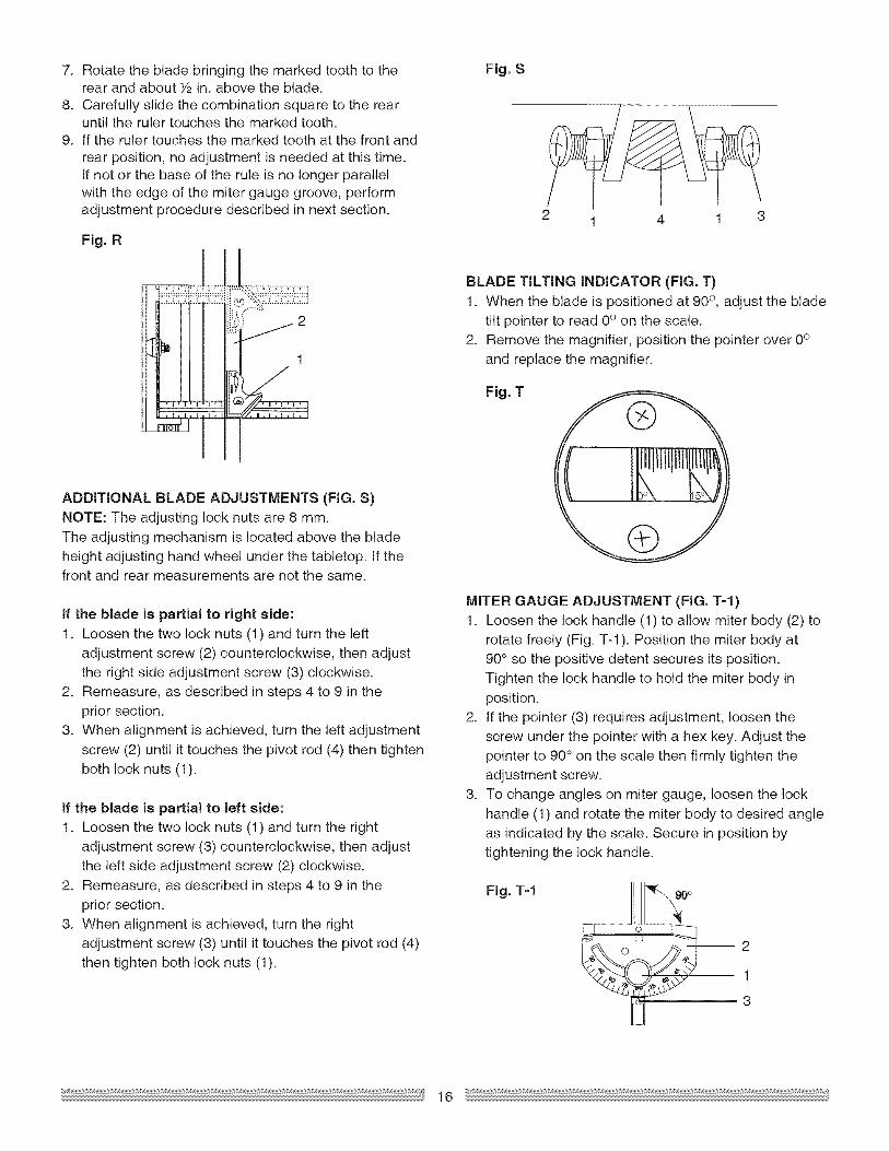
7. RotatethebladebringingthemarkedtoothtotherearandaboutYzin. above the blade.
8. Carefully slide the combination square to the rearuntil the ruler touches the marked tooth.
9. tf the ruler touches the marked tooth at the front andrear position, no adjustment is needed at this time.tf not or the base of the rule is no longer parallelwith the edge of the miter gauge groove, performadjustment procedure described in next section.
Fig. R
Fig. S
2 1 4 3
,,_,============================
j21
BLADE TILTING INDICATOR (FIG. T)
1. When the blade is positioned at 90° , adjust the bladetilt pointer to read 0° on the scale.
2. Remove the magnifier, position the pointer over 0°and replace the magnifier.
Fig. T
ADDITIONAL BLADE ADJUSTMENTS (FIG. S)
NOTE: The adjusting lock nuts are 8 ram.The adjusting mechanism is located above the bladeheight adjusting hand wheel under the tabletop, tf thefront and rear measurements are not the same.
If the blade is partial to right aide:
1. Loosen the two lock nuts (1) and turn the leftadjustment screw (2) counterclockwise, then adjustthe right side adjustment screw (3) clockwise.
2. Remeasure, as described in steps 4 to 9 in the
prior section.3. When alignment is achieved, turn the left adjustment
screw (2) until it touches the pivot rod (4) then tighten
both lock nuts (1).
if the blade is partial to left aide:1. Loosen the two lock nuts (1) and turn the right
adjustment screw (3) counterclockwise, then adjustthe left side adjustment screw (2) clockwise.
2. Remeasure, as described in steps 4 to 9 in theprior section.
3. When alignment is achieved, turn the right
adjustment screw (3) until it touches the pivot rod (4)then tighten both lock nuts (1).
MITER GAUGE ADJUSTMENT (FIG. T=I)1. Loosen the lock handle (1) to allow miter body (2) to
rotate freely (Fig. T-1 ). Position the miter body at90° so the positive detent secures its position.Tighten the lock handle to hold the miter body in
position.2. tf the pointer (3) requires adjustment, loosen the
screw under the pointer with a hex key. Adjust the
pointer to 90° on the scale then firmly tighten theadjustment screw.
3. To change angles on miter gauge, loosen the lock
handle (1) and rotate the miter body to desired angleas indicated by the scale. Secure in position bytightening the lock handle.
Fig. T-1
2
1
3
16
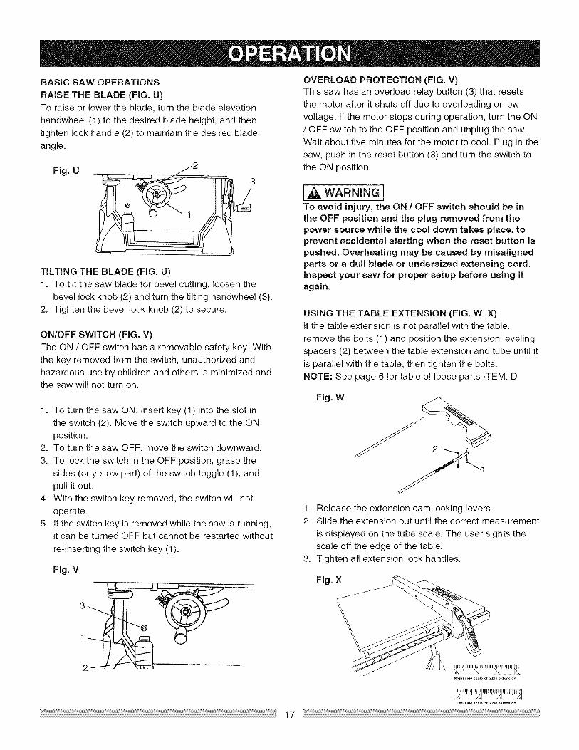
BASICSAWOPERATIONSRAISETHEBLADE (FIG. U)To raise or lower the blade, turn the blade elevation
handwheel (1) to the desired blade height, and thentighten lock handle (2) to maintain the desired bladeangle.
Fig. U
TiLTiNG THE BLADE (FIG. U)1. To tilt the saw blade for bevel cutting, loosen the
bevel lock knob (2) and turn the tilting handwheel (3).2. Tighten the bevel lock knob (2) to secure.
ON/OFF SWITCH (FIG. V)The ON / OFF switch has a removable safety key. With
the key removed from the switch, unauthorized andhazardous use by children and others is minimized andthe saw will not turn on.
1. To turn the saw ON, insert key (1) into the slot inthe switch (2). Move the switch upward to the ON
position.2. To turn the saw OFF, move the switch downward.
3. To lock the switch in the OFF position, grasp thesides (or yellow part) of the switch toggle (1), and
pull it out.4. With the switch key removed, the switch will not
operate.5. tf the switch key is removed while the saw is running,
it can be turned OFF but cannot be restarted without
re-inserting the switch key (1).
Fig. V
OVERLOAD PROTECTION (FIG. V)This saw has an overload relay button (3) that resets
the motor after it shuts off due to overloading or lowvoltage, tf the motor stops during operation, turn the ON/ OFF switch to the OFF position and unplug the saw.
Wait about five minutes for the motor to cool. Plug in thesaw, push in the reset button (3) and turn the switch tothe ON position.
IA WARNINGITo avoid injury, the ON / OFF switch should be inthe OFF position and the plug removed from thepower source while the cool down takes place, toprevent accidental starting when the reset button ispushed. Overheating may be caused by misalignedparts or a dull blade or undersized extensing cord.inspect your saw for proper setup before using itagain.
USING THE TABLE EXTENSION (FIG. W, X)tf the table extension is not parallel with the table,remove the bolts (1) and position the extension levelingspacers (2) between the table extension and tube until it
is parallel with the table, then tighten the bolts.NOTE: See page 6 for table of loose parts ITEM: D
Fig. W
1. Release the extension cam locking levers.2. Slide the extension out until the correct measurement
is displayed on the tube scale. The user sights thescale off the edge of the table.
3. Tighten all extension lock handles.
Fig. X
Right sidesca_e of table e×tens_on
Left side scale of table extension
17
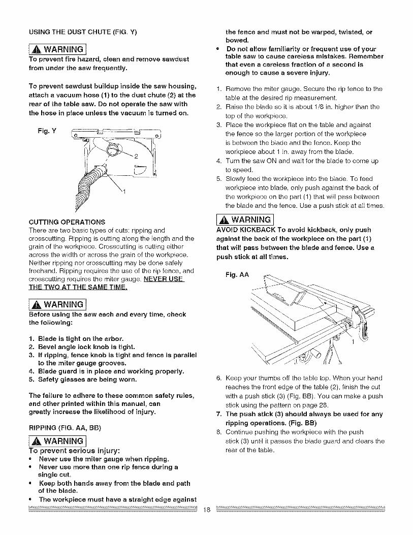
USINGTHE DUST CHUTE (FIG. Y)
IA WARNINGITo prevent fire hazard, clean and remove sawdustfrom under the saw frequently.
To prevent sawdust buildup inside the saw housing,attach a vacuum hose (1) to the dust chute (2) at the
rear of the table saw. Do not operate the saw withthe hose in place unless the vacuum is turned on.
Fig. Y
CUTTING OPERATIONS
There are two basic types of cuts: ripping andcrosscutting. Ripping is cutting along the length and thegrain of the workpiece. Crosscutting is cutting eitheracross the width or across the grain of the workpiece.Neither ripping nor crosscutting may be done safelyfreehand. Ripping requires the use of the rip fence, andcrosscutting requires the miter gauge. NEVER USETHE TWO AT THE SAME TIME.
the fence and must not be warped, twisted, orbowed.
Do not allow familiarity or frequent use of yourtable saw to cause careless mistakes. Rememberthat even a careless fraction of a second isenough to cause a severe injury.
1. Remove the miter gauge. Secure the rip fence to the
table at the desired rip measurement.2. Raise the blade so it is about 1/8 in. higher than the
top of the workpiece.
3. Place the workpiece fiat on the table and againstthe fence so the larger portion of the workpieceis between the blade and the fence. Keep theworkpiece about 1 in. away from the blade.
4. Turn the saw ON and wait for the blade to come upto speed.
5. Slowly feed the workpiece into the blade. To feed
workpiece into blade, only push against the back ofthe workpiece on the part (1) that will pass betweenthe blade and the fence. Use a push stick at all times.
la,WARNINGIAVOID KICKBACK To avoid kickback, only pushagainst the back of the workpiece on the part (1)that will pass between the blade and fence. Use a
push stick at all times.
Fig. AA
[A WARNI"GIBefore using the saw each and every time, checkthe following:
1. Blade is tight on the arbor.2. Bevel angle lock knob is tight.3. if ripping, fence knob is tight and fence is parallel
to the miter gauge grooves.4. Blade guard is in place and working properly.5. Safety glasses are being worn.
The failure to adhere to these common safety rules,and other printed within this manual, cangreatly increase the likelihood of injury.
RIPPING (FIG. AA, BB)
[A WARNINGITo prevent serious injury:• Never use the miter gauge when ripping.= Never use more than one rip fence during a
single cut.= Keep both hands away from the blade and path
of the blade.
• The workpiece must have a straight edge against
6. Keep your thumbs off the table top. When your hand
reaches the front edge of the table (2), finish the cutwith a push stick (3) (Fig. BB). You can make a pushstick using the pattern on page 28.
7. The push stick (3) should always be used for anyripping operations. (Fig. BB)
8. Continue pushing the workpiece with the push
stick (3) until it passes the blade guard and clears therear of the table.
18
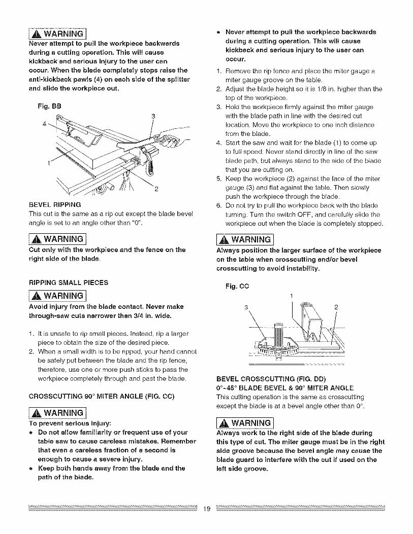
[_, WARNING INever attempt to pull the workpiece backwardsduring a cutting operation, This will cause
kickback and serious injury to the user canoccur, When the blade completely stops raise theanti-kickback pawls (4) on each side of the splitter
and slide the workpiece out,
Fig, BB
4
1
BEVEL RIPPING
This cut is the same as a rip cut except the blade bevelangle is set to an angle other than "0".
[_, WARNING i
Cut only with the workpiece and the fence on theright side of the blade.
RiPPiNG SMALL PIECES
[A WARNINGIAvoid injury from the blade contact. Never make
through=saw cuts narrower than 3/4 in. wide.
1. it is unsafe to rip small pieces, instead, rip a larger
piece to obtain the size of the desired piece.2. When a small width is to be ripped, your hand cannot
be safely put between the blade and the rip fence,
therefore, use one or more push sticks to pass theworkpiece completely through and past the blade.
CROSSCUTTING 90 ° MITER ANGLE (FIG. CC)
[_, WARNING I
To prevent serious injury:= Do not allow familiarity or frequent use of your
table saw to cause careless mistakes, Rememberthat even a careless fraction of a second is
enough to cause a severe injury,• Keep both hands away from the blade and the
path of the blade.
Never attempt to pull the workpiece backwards
during a cutting operation. This will causekickback and serious injury to the user canOccur,
1. Remove the rip fence and place the miter gauge amiter gauge groove on the table.
2. Adjust the blade height so it is 1/8 in. higher than thetop of the workpiece.
3. Hold the workpiece firmly against the miter gauge
with the blade path in line with the desired cutlocation. Move the workpiece to one inch distancefrom the blade.
4. Start the saw and wait for the blade (1) to come up
to full speed. Never stand directly in line of the sawblade path, but always stand to the side of the bladethat you are cutting on.
5. Keep the workpiece (2) against the face of the mitergauge (3) and flat against the table. Then slowlypush the workpiece through the blade.
6. Do not try to pull the workpiece back with the blade
turning. Turn the switch OFF, and carefully slide theworkpiece out when the blade is completely stopped.
I A, WARNING !Always position the larger surface of the workpieceon the table when crosscutting and/or bevel
crosscutting to avoid instability.
Fig, CC1
u
BEVEL CROSSCUTTING (FIG. DD)0o~45 ° BLADE BEVEL & 90° MITER ANGLE
This cutting operation is the same as crosscutting
except the blade is at a bevel angle other than 0°
I,A WARNING IAlways work to the right side of the blade duringthis type of cut. The miter gauge must be in the rightside groove because the bevel angle may cause theblade guard to interfere with the cut if used on the
left side groove.
19
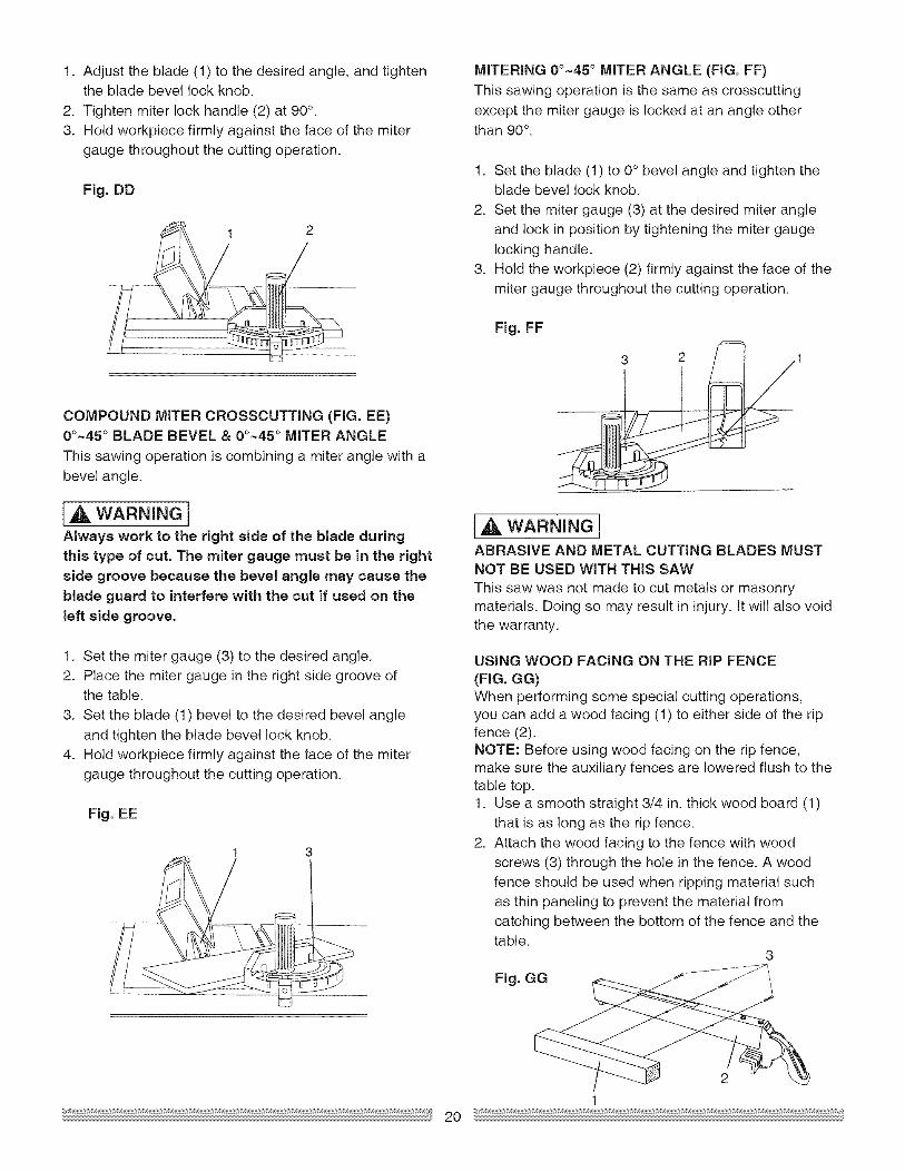
1. Adjusttheblade(1)tothedesiredangle,andtightenthebladebevellockknob.
2. Tightenmiterlockhandle(2)at 90°.3. Hold workpiece firmly against the face of the miter
gauge throughout the cutting operation.
Fig, DD
COMPOUND MITER CROSSCUTTING (FIG. EL)0o-45 ° BLADE BEVEL & 0o-45 ° MITER ANGLE
This sawing operation is combining a miter angle with abevel angle.
[4 WARNINGIAlways work to the right side of the blade duringthis type of cut. The miter gauge must be in the right
side groove because the bevel angle may cause theblade guard to interfere with the cut if used on the
left side groove.
1. Set the miter gauge (3) to the desired angle.2. Place the miter gauge in the right side groove of
the table.
3. Set the blade (1) bevel to the desired bevel angleand tighten the blade bevel lock knob.
4. Hold workpiece firmly against the face of the miter
gauge throughout the cutting operation.
Fig. EE
I 3
MiTERiNG 0o-45 ° MITER ANGLE (FIG. FF)
This sawing operation is the same as crosscuttingexcept the miter gauge is locked at an angle otherthan 90°.
1. Set the blade (1) to 0° bevel angle and tighten theblade bevel lock knob.
2. Set the miter gauge (3) at the desired miter angle
and lock in position by tightening the miter gaugelocking handle.
3. Hold the workpiece (2) firmly against the face of the
miter gauge throughout the cutting operation.
Fig. FF
14 WARNINe!ABRASIVE AND METAL CUTTING BLADES MUSTNOT BE USED WiTH THiS SAW
This saw was not made to cut metals or masonrymaterials. Doing so may result in injury, tt will also voidthe warranty.
USING WOOD FACING ON THE RiP FENCE(FIG. GG)When performing some special cutting operations,you can add a wood facing (1) to either side of the ripfence (2).NOTE: Before using wood facing on the rip fence,make sure the auxiliary fences are lowered flush to thetable top.1. Use a smooth straight 3/4 in. thick wood board (1)
that is as long as the rip fence.2. Attach the wood facing to the fence with wood
screws (3) through the hole in the fence. A wood
fence should be used when ripping material suchas thin paneling to prevent the material fromcatching between the bottom of the fence and thetable.
3
Fig. GG
2
12O
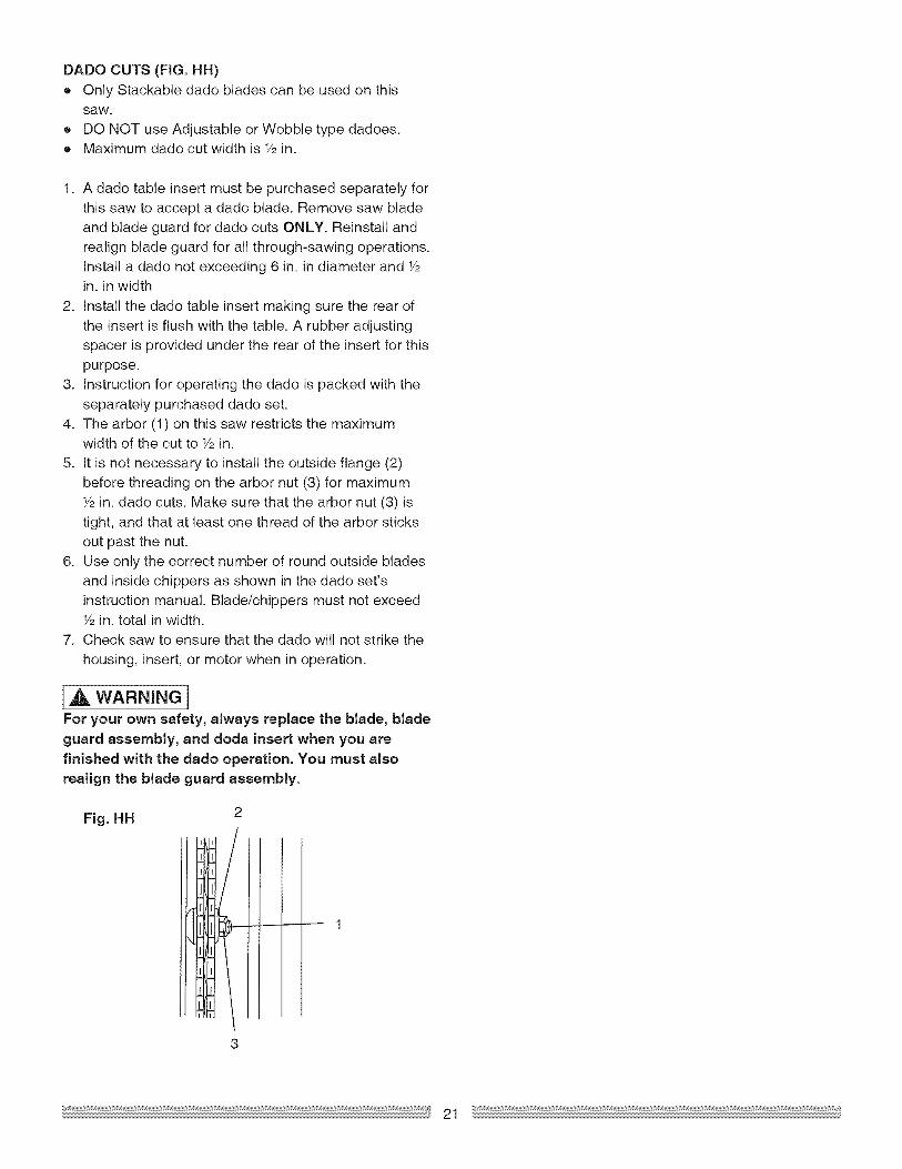
DADOCUTS(FIG. HH)
• Only Stackable dado blades can be used on thissaw.
• DO NOT use Adjustable or Wobble type dadoes.• Maximum dado cut width is Y2in.
1. A dado table insert must be purchased separately forthis saw to accept a dado blade. Remove saw blade
and blade guard for dado cuts ONLY. Reinstall andrealign blade guard for all through-sawing operations.Install a dado not exceeding 6 in. in diameter and Y2in. in width
2. Install the dado table insert making sure the rear ofthe insert is flush with the table. A rubber adjusting
spacer is provided under the rear of the insert for thispurpose.
3. Instruction for operating the dado is packed with the
separately purchased dado set.4. The arbor (1) on this saw restricts the maximum
width of the cut to Y2in.
5. tt is not necessary to install the outside flange (2)
before threading on the arbor nut (3) for maximumY2in. dado cuts. Make sure that the arbor nut (3) istight, and that at least one thread of the arbor sticks
out past the nut.6. Use only the correct number of round outside blades
and inside chippers as shown in the dado set'sinstruction manual. Blade/chippers must not exceedF2in. total in width.
7. Check saw to ensure that the dado will not strike the
housing, insert, or motor when in operation.
[_ WARNINGIFor your own safety, always replace the blade, bladeguard assembly, and doda insert when you are
finished with the dado operation. You must alsorealign the blade guard assembly.
Fig. HH
I|111
---- 1
MAiNTAiNING YOUR TABLE SAW
GENERAL MAINTENANCE
[A WARNINGIBefore maintaining or lubricating the saw, turnswitch off, remove the switch key, and unplug theSaW.
1. Clean out all sawdust that has accumulated insidethe saw cabinet and the motor.
2. Polish the saw table with an automotive wax to keepit clean and to make it easier to slide the workpiece.
3. Clean cutting blades with pitch and gum remover.
4. Immediately replace a worn, cut, or damaged powercord.
WARNINGIAll electrical or mechanical repairs should beattempted only by a trained repair technician.Contact the nearest Sears Service Center for
service. Use only identical replacement parts. Anyother parts may create a hazard.
5. Use liquid dish washing detergent and water to cleanall plastic parts.NOTE: Certain cleaning chemicals can damage
plastic parts.6. Avoid use of the following cleaning chemicals or
solvents: ammonia and household detergents
containing ammonia.
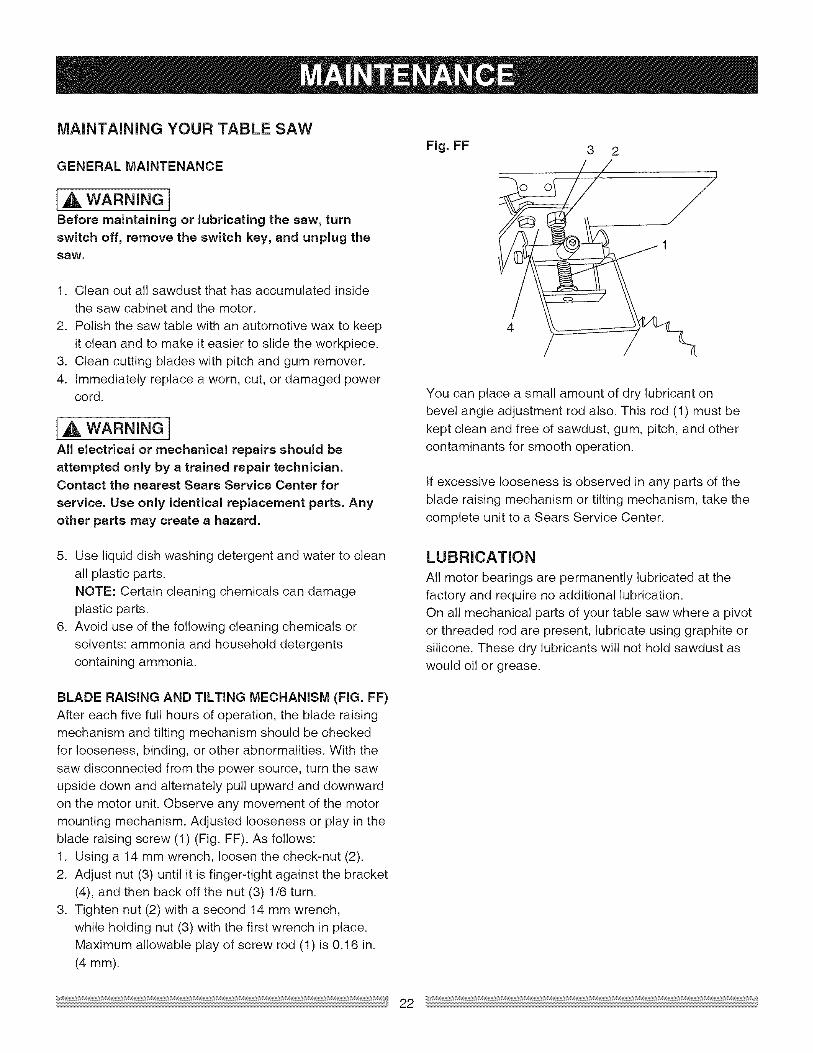
BLADE RAiSiNG AND TiLTiNG MECHANISM (FIG. FF)After each five full hours of operation, the blade raising
mechanism and tilting mechanism should be checkedfor looseness, binding, or other abnormalities. With thesaw disconnected from the power source, turn the saw
upside down and alternately pull upward and downwardon the motor unit. Observe any movement of the motormounting mechanism. Adjusted looseness or play in theblade raising screw (1) (Fig. FF). As follows:
1. Using a 14 mm wrench, loosen the check-nut (2).2. Adjust nut (3) until it is finger-tight against the bracket
(4), and then back off the nut (3) 1/6 turn.
3. Tighten nut (2) with a second 14 mm wrench,while holding nut (3) with the first wrench in place.Maximum allowable play of screw rod (1) is 0.16 in.
(4 ram).
Fig. FF
1
You can place a small amount of dry lubricant on
bevel angle adjustment rod also. This rod (1) must bekept clean and free of sawdust, gum, pitch, and othercontaminants for smooth operation.
tf excessive looseness is observed in any parts of theblade raising mechanism or tilting mechanism, take the
complete unit to a Sears Service Center.
LUBRICATION
All motor bearings are permanently lubricated at thefactory and require no additional lubrication.On all mechanical parts of your table saw where a pivot
or threaded rod are present, lubricate using graphite orsilicone. These dry lubricants will not hold sawdust aswould oil or grease.
22

[A WARNINOITo avoid injury from an accidental start, turn the switch OFF remove the switch key and always remove theplug from the power source before making any adjustments,
= If for any reason the motor will not run, contact Sears Service Center at f =800=4-MY=HOME®,
SYMPTOM POSSIBLE CAUSES CORRECTIVE ACTION
Saw will not start. 1. Saw not plugged in. 1. Plug in saw.
Does not make accurate 45°
and 90 ° rip cuts.
2. Fuse blown or circuit breaker tripped.
3. Cord damaged.4. Debris in on/off switch
1. Positive stop not adjusted correctly.
2. Tilt angle pointer not set accurately. 2.
Material pinched blade when 1. 1.ripping. 2.
Material binds on splitter.
Saw makes unsatisfactorycuts.
Material kicked back fromblade.
Rip fence not aligned with blade.Warped wood, edge against fence isnot straight.
1. Splitter not aligned correctly with blade.1. Dull blade.2. Blade mounted backwards.
3. Gum or pitch on blade.
4. Incorrect blade for work being done.5. Gum or pitch on blade causing erratic
feed.
1. Rip fence out of adjustment.2. Splitter not aligned with blade.
3. Feeding stock without rip fence.4. Splitter not in place.5. Dull blade.
6. The operator letting go of materialbefore it is past saw blade.
7. Miter angle lock knob is not tight.
2. Replace fuse or reset circuit breaker.
3. Replace power cord.4. Unplug and remove switch from saw.
Separate switch in half and clean anydebris within.
1. Check blade with square and adjustpositive stop.Check blade with square and adjustto zero.Check and align rip fence and blade
to miter gauge groove.2. Select another piece of wood.
1. Check and align splitter with blade.
1. Replace blade.2. Turn the blade around.3. Remove blade and clean with
turpentine and coarse steel wool.4. Change the blade.5. Remove blade and clean table with
turpentine and steel wool.
1. Align rip fence with miter gauge
groove.2. Align splitter with blade.3. Install and use rip fence.4. Install and use splitter. (with guard)
5. Replace blade.6. Push material all the way past saw
blade before releasing work.
7. Tighten knob.Blade does not raise or tilt 1. Sawdust and dirt in elevation/tilting 1. Brush or blow out loose dust and dirt.freely, mechanisms.Blade does not come up to 1. Extension cord too light or too long. 1. Replace with adequate size cord.speed. Reset trips too easily. 2. Low house voltage. 2. Contact your electric company.
Machine vibrates excessively. 1. Saw not mounted securely to 1. Tighten all mounting hardware.workbench. 2. Reposition on flat level surface.
2. Bench on uneven floor. 3. Replace blade.
3. Damaged saw blade.
Does not make accurate 45° 1. Miter gauge out of adjustment. 1. Adjust miter gauge.and 90 ° crosscuts.

10 in. TABLE SAW MODEL NO. 137.248850
[A WARNINGIWhen servicing use only CRAFTSMAN replacement parts, Use of any other parts many create a HAZARDor cause product damage, Any attempt to repair or replace electrical parts on this Table Saw may create aHAZARD unless repair is done by a qualified service technician. Repair service is available at your nearestSears Service Center,
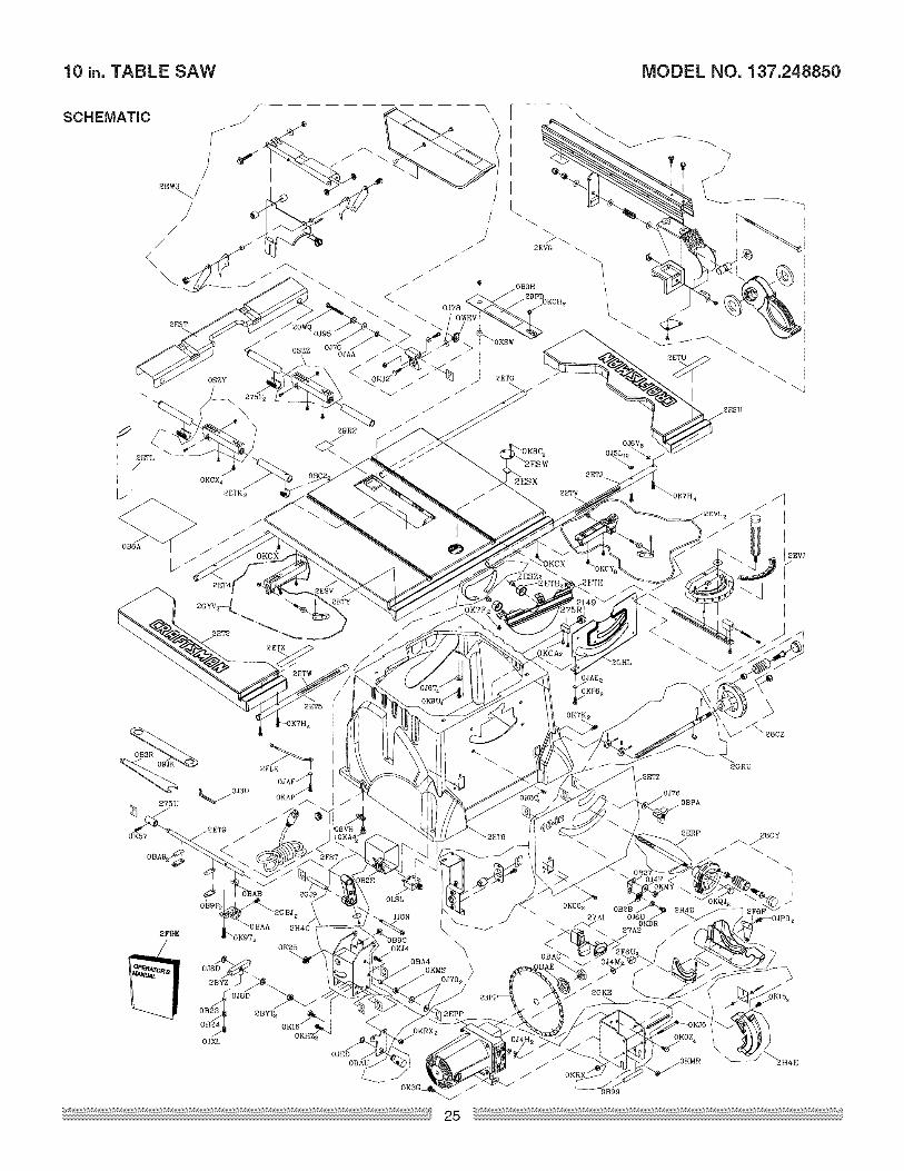
PARTS LiST FOR TABLE SAW SCHEIV1ATIC
I.D. Description Size QTY
08VH CORD CLAMP
09JK WRENCH
0B23 SADDLE
0B24 SPRING
0B27 POINTER BRACKET
0B2B NEEDLE POINTER
0B2E SWFCH BOX
0B3H INSERT #23
0B3R WRENCH
0BBA WARNING STICK LABE
0B99 SPACER
0B9C PLUNGFR HOUSING
0B9P CLAMP
0BA4 SPACER
0BA9 SPACER
0BAA CLAMP
0BAB SHIM
0BAC S_T NUT
0BAF ARBOR COLLAR
0BAU SUPPORTING PLATE
0BC2 LOCATION SPAT
0BPA LOCK KNOB
0J3U HEX WRENCH
0J4F FLAT WASHER @8"16 25
0J4H FLAT WASHER @030 02
0J4M FLAT WASHER (p 2_21 I
0J5L FLAT WASHER (p5"10 03 10
0J6T FLAT WASHER 3/163/4 1/16 4
0J6U FLAT WASHER 3/161/2 3/64 1
0J6V FLAT WASHER 3/163/8 0022 8
0J70 FLAT WASHER 1/4"3/4 7/64 2
0J76 FLAT WASHER 1/4"3/4 1/1B 2
0J78 FLAT WASHER 1/4"1/2 3/32 1
0J8D FLAT WASHER 3/83/4 5/64 2
0J95 SPRING WASHER (p6 1
0JAA WASHFR 98 1
0JAE EXTERNAL TOOTH LOCK WASHER @4 2
0JAF EXTERNAL TOOTH LOCK WASHER @5 1
0JED C RING 1
0JP9 HEX HD BOLT M5*0B 12 2
0JXL HEX SOC SET SCREW M10"1 5 12 1
0KOZ HEX HD SCREW AND WASHER M8"1 25 1B 4
0K15 HEX HD SCREW AND WASHER M6_1 0 20 3
0K16 HEX HD SCREW AND WASHER M8"1 25 1B 1
0K25 HEX SOCKET HDCAP SCREW M5"08 20 1
0K3G CR RE PAN HD SCRFW & WASHER M5"08 12 1
0K57 CR RE COUNT HD SCRFW M5"08 1B 1
0K7F CR RE ROUND WASHER HD SCREW M5"08 8 2
0K7H CR RE ROUND WASHER HD SCREW M5"08 25 8
0K7K CR RE ROUND WASHER HD SCREW M6_1 0 12 2
0K8C CR RECOUNT HD TAPPING SCREW M4"18 10 6
0K9T HEX HD TAPP NG SCREW M5"1B 1B 6
0K9U HEX HD TAPPNG SCRFW M5"1B 25 4
0KA4 CR RE PAN HD TAPPING SCREW M4"1B 1B 2
0KAP CR RE PAN HD TAPPING SCREW M5"08 10 1
0KC8 CR RE TRUSS HD TAPPING SCREW M41B 1B 2
0KCA CR RE TRUSS HD TAPPING SCREW M5"12 12 2
0KCH CR RE PAN HFAD TAPPING & WASHER SCRFW M5"08 12 2
0KCX CR RE PAN HD PLAIN WASHER TAPPING SCREW M5"08 10 6
0KCY CR RE PAN HD PLAIN WASHER TAPPING SCREW M5"08 12 8
0KDR CR RE PAN HD SCRFW M5"08 10 1
0KFB CR RE PAN HD SCRFW M4"07 8 2
0KHZ CAP HD SQ NECK BOLT M6"1 0 12 2
0K J2 CAP HD SQ NECK BOLT M6"1 0 25 1
0K J4 CAP HD SQ NECK BOLT M6"1 0 35 1
0K J5 CAP HD. SQ NECK BOLT M6_1 0 80 1
0KMR HEX NUT M5_08 F 4 1
LD, Description Size
0KMS HEX NUT M6 0T 5
0KMY HEX. NUT M8 25T 65
0KQJ CROWN NUT M8 25T 125
0KRX HEXAGON NUT AND FLAT WASHER M6 _ 0
0KSW STRAIN RELIFF
0LS CIRCUIT BREAKER SWITCH
0SZY SLID NG BASE ASS'Y
0SZZ SLID NG BASE ASS'Y
0WFV KNOB
118N CR RE PAN HD SCREW M6 0 55
20WQ HEX HD BOLT M6* 0 50
2149 KNOB
23PP BLAD F
275F LOCAT ON SEAT
275R LOCAF ON SEAT
275U SPACER
27A ROCKER SWITCH
27A2 SWITCH KEY
28CY HAND WHEE ASSY
28CZ HAND WHEEL ASSY
29PD WARNING LABEL
29R2 WARNING LABEL
2BYT HEX NUT
2BYZ BRACKET
2EPP MOTOR
2ERP HEIGHT REGULATING BOLT ASS'Y
2EST EXTENTION WING
2ESU EXTENTION WING #AW
2ESV TABLE #AW
2ESW COVER
2ESX NEEDL E POINTER
2ESZ SPECIAL BOLT
2ET2 EXTENTION WING #AW
2ET4 UPPER TUBE
2ET5 UPPER TUBE
2ET6 BODY SHEL
2ET9 ANGLE ROD
2ETB ROLLING WHEE
2ETE PLASTIC GUARD
2ETG UPPER TUBE
2ETJ UPPER TUBE
2ETK UPPER TUBE
2ETL DUST BAG
2ETU SCALE
2ETV SCALE
2ETW SCALE
2ETX SCALE
2ETY SCALE
2ETZ LABEL
2EVG RIP FENCE ASS'Y
2EVJ MITER GAUG E ASS'Y
2EV SLID NG BASE ASS'Y
2EW3 BLADF GUARD ASS'Y
2F6F RETA NING CLIP
2F6U COLLAR
2F9E INSTRUCTIONS MANUAL
2FLK LEAD WiRE ASSY
2FST POWER CABLE ASS'Y
2GBJ CR RE PAN HD SCREW M5"08 2
2GHL RETA NING CLIP
2G J9 SPACER
2GK F BRACKET GROUP ASS'Y
2GRU BEVEL ANGL E ADJUSTMENT ASS'Y
2GYV SLID NG BASE ASS'Y
2H4C PULEY ASS'Y
2H4D MOVAB E COVER ASS'Y
2H4E FRONT COVER ASS'Y
QTY
10 in. TABLE SAW MODEL NO. 137.248850
/
SCHEMATIC
/
2EST
2ET4
2ET2
2ETJ
2ETV
//
,0J76
/ ODPA
2GRU
<
/ZGKE
0JED _KOZ4
0BAU / _0KMR \--/ OKRX
OKSG
10 in. TABLE SAW MODEL NO. 137.248850
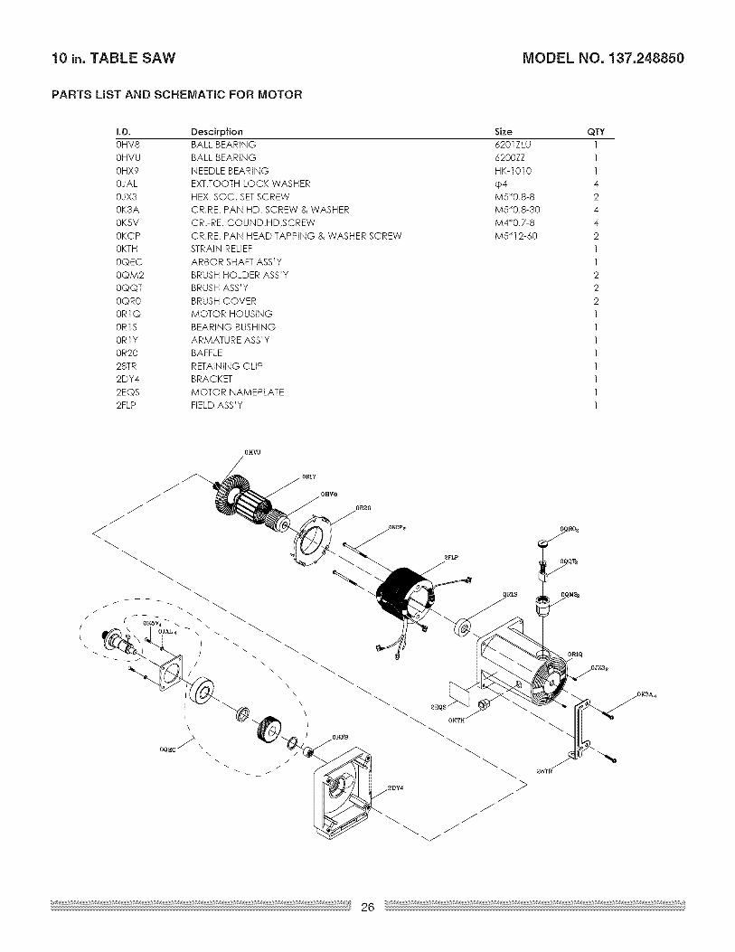
PARTS LiST AND SCHEMATIC FOR MOTOR
I.D. Descirpfion0HV8 BALL BEARING
0HVU BALL BEARING
0HX9 NEEDLE BEARING
0JAL EXT.TOOTH LOCK WASHER
0JX3 HEX. SOC. SETSCREW0K3A CR.RE. PAN HD. SCREW & WASHER
0K5V CR.-RE. COUND.HD.SCREW
0KCP CR.RE. PAN HEAD TAPPING & WASHER SCREW
0KTH STRAIN RELIEF
0QEC ARBOR SHAFT ASS'Y
0QM2 BRUSH HOLDER ASS'Y
0QQT BRUSH ASS'Y
0QR0 BRUSH COVER0R1Q MOTOR HOUSING
0R1S BEARING BUSHING
0R1Y ARMATURE ASS'Y
0R20 BAFFLE
28TR RETAINING CLIP2DY4 BRACKET
2EQS MOTOR NAMEPLATE2FLP FIELD ASS 'Y
Size6201Z LU
6200ZZ
HK-1010
cp4M5"0.8-8M5"0.8-30
M4"0.7-8
M5 .12-60
QTY1
1
1
4
24
4
2
1
1
2
22
1
1
1
1
11
1
1
0HgV
/
!
\
OqEC/_ \\
OHV8
\
\
\
OH_
OR20
2FLP
ORIS
ORIQ
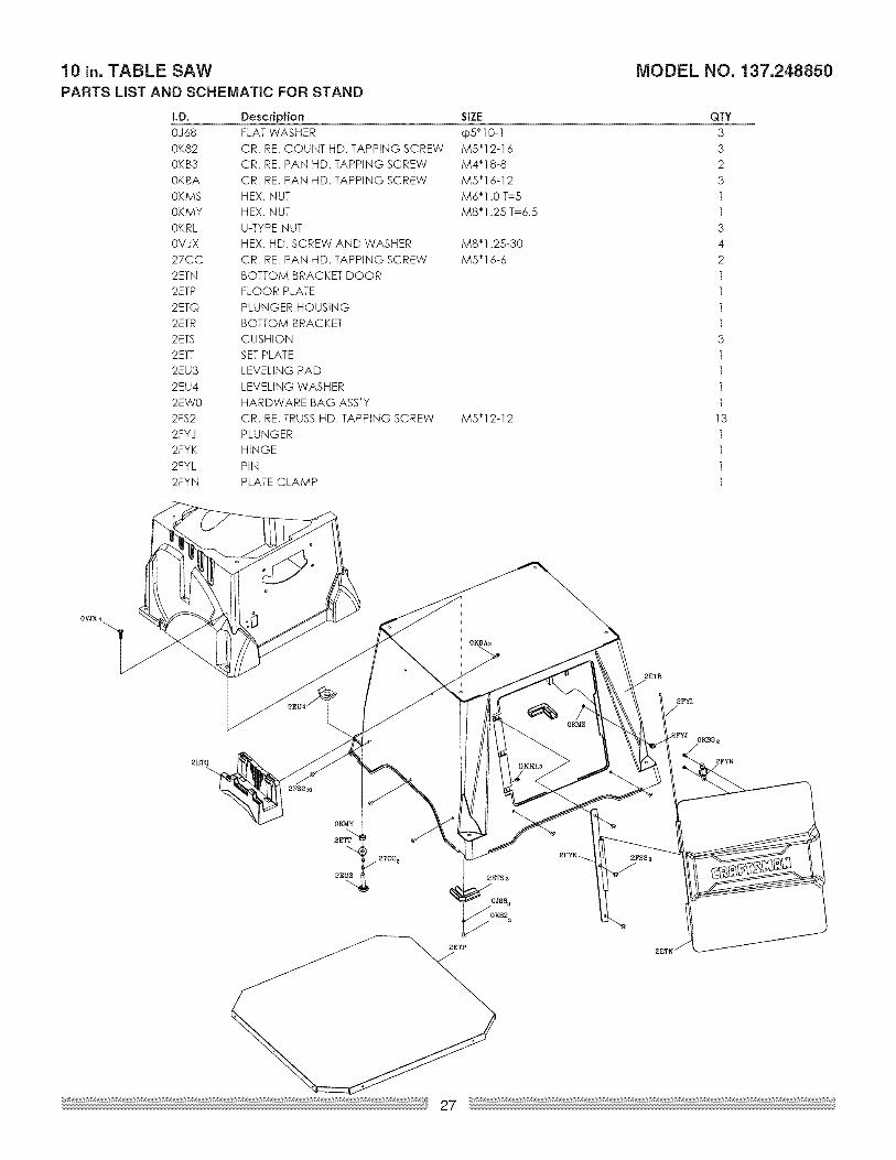
10 in. TABLE SAW MODEL NO. 137.248850PARTS LiST AND SCHEMATIC FOR STAND
LB.
0J68
0K820KB3
0KBA
0KMS
0KMY
0KRL0VJX
27CC
2ETN
2ETP
2ETQ
2ETR2ETS
2ETT
2EU3
2EU4
2EW0
2FS2
2FYJ2FYK
2FYL
2FYN
Description SIZE
FLAT WASHER cp5_10-1CR. RE. COUNT HD. TAPPING SCREW M5"12-16CR. RE. PAN HD. TAPPING SCREW M4"18-8
CR. RE. PAN HD. TAPPING SCREW M5"16-12
HEX. NUT M6"1.0 T=5
HEX. NUT M8"1.25 T=6.5
U-TYPE NUTHEX. HD. SCREW AND WASHER M8"1.25-30
CR. RE. PAN HD. TAPPING SCREW M5"16-6
BOTTOM BRACKET DOOR
FLOOR PLATE
PLUNGER HOUSING
BOTTOM BRACKETCUSHION
SETPLATE
LEVELING PAD
LEVELING WASHER
HARDWARE BAG ASS'Y
CR. RE. TRUSS HD. TAPPING SCREW M5"12-12
PLUNGERHINGE
PiN
PLATE CLAMP
QTY
3
32
3
1
1
34
2
1
1
1
13
1
1
1
1
13
11
1
1
OVJX 4
OKMS
2ETR
_FYL
2FYN
OKMY
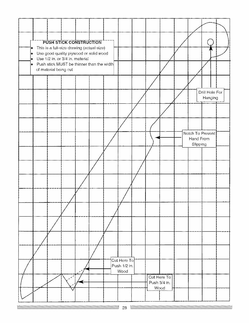
PUSH STICK CONSTRUCTION
This is a full-size drawing (actual size)
Use good quality plywood or solid woodUse 1/2 in. or 3/4 in. materialPush stick MUST be thinner than the width
of material being cut/
Z
//
Drill Hole For
Hanging
/
/
Notch To Prevent
Hand From
Slipping
Cut Here ToPush 1/2 in.
Wood
Cut Here ToPush 3/4 in.
Wood
r


Your Home
For repair - in your home - of all major brand appliances,
lawn and garden equipment, or heating and cooling systems,
no matter who made it, no matter who sold itt
For the replacement parts, accessories and
owner's manuals that you need to do-it-yourself.
For Sears professional installation of home appliances
and items like garage door openers and water heaters.
1-800-4-1VlY-HOIVlE ® (1=800=469=4663)Call anytime, day or night (U.S.A. and Canada)
www.sesrs.oorn www.sesrs.c8
Our Home
For repair of carry-in items like vacuums, lawn equipment,
and electronics, call or go on-line for the location of your nearest
Sears Parts & Repair Center.
1-800=488-1222
Call anytime, day or night (U.S.A. only)
www.sears.oorn
To purchase a protection agreement (U.S.A.)
or maintenance agreement (Canada) on a product serviced by Sears:
1-800-827-6655 (U.S.A.) 1-800-361-6665 (Canada)
Para pedir servicio de reparaci6n
a domicilio, y para ordenar piezas:
l=888-SU=HOGAR _'(1-888-784-6427)
Au Canada pour service en frangais:
I=800=LE=FOYER "°
(1-800-533-6937)www.sears.ca
TM M® Registered Trademark / Trademark / s Service Mark of Sears Brands, LLC
TM M® Marca Registrada / Marca de Fb.brica / s Marca de Servicio de Sears Brands, LLC
MDMcMarque de commerce / Marque deposee de Sears Brands, LLC © Sears Brands, LLC