Embed Size (px)
Citation preview
Page 1
Manual No. 161703 (rev 02/09)©2009, Printed in USA
DITEQ Corporation1250 NW Main Street
Lee’s Summit, MO 64086 USAPhone: 816-246-5515
Fax: 816-246-1530www.DITEQ.com
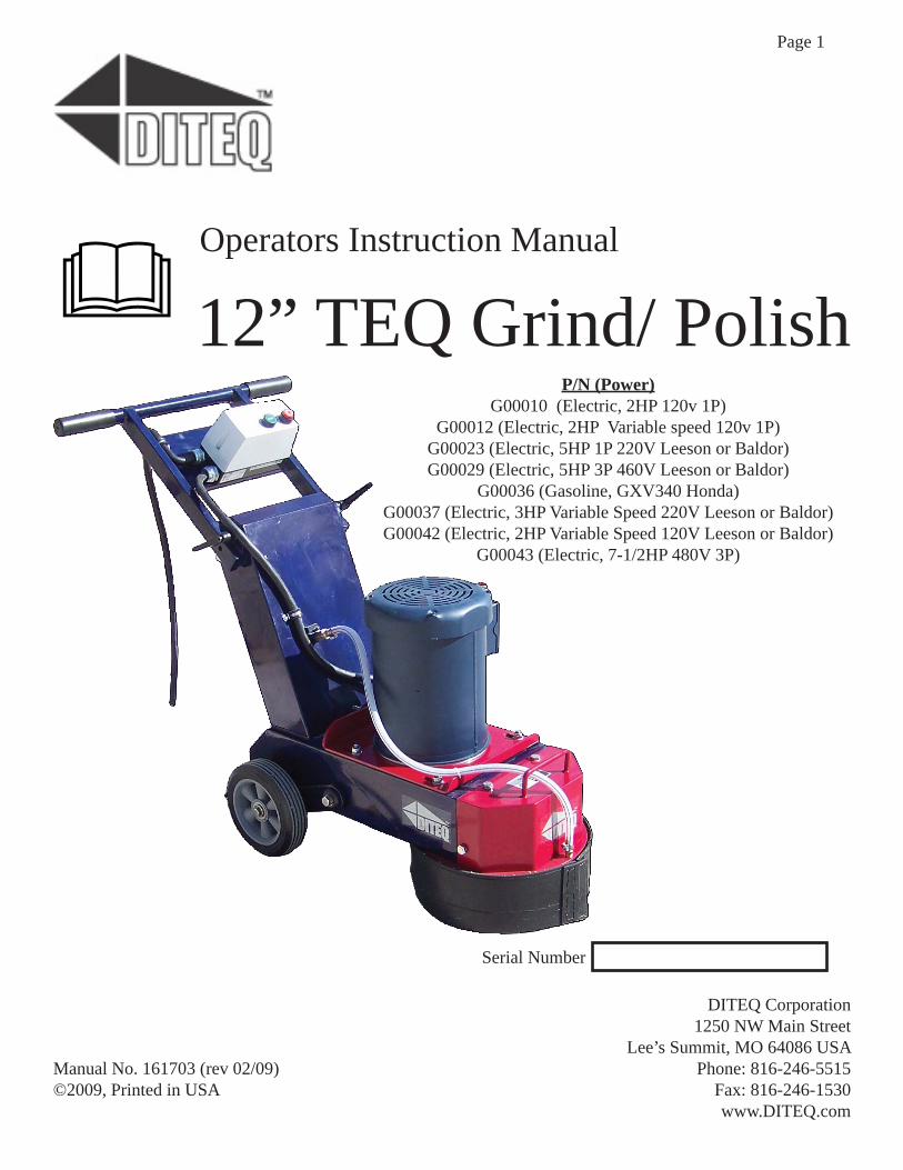
12” TEQ Grind/ PolishP/N (Power)
G00010 (Electric, 2HP 120v 1P)G00012 (Electric, 2HP Variable speed 120v 1P)
G00023 (Electric, 5HP 1P 220V Leeson or Baldor)G00029 (Electric, 5HP 3P 460V Leeson or Baldor)
G00036 (Gasoline, GXV340 Honda)G00037 (Electric, 3HP Variable Speed 220V Leeson or Baldor)G00042 (Electric, 2HP Variable Speed 120V Leeson or Baldor)
G00043 (Electric, 7-1/2HP 480V 3P)
Operators Instruction Manual
Serial Number
Page 2
©2009
Completely read and fully understand the contents of this Operators Instruction Manual before attempting to operate this equipment. Death or serious injury could result from the improper use of this equipment.
Some of the safety message in the manual are em-phasized with a graphic safety message alert symbol of DANGER, WARNING or CAUTION.
Indicates an imminent hazard which, if not avoided, will result in death or serious injury
Indicates an imminent hazard which, if not avoided, can result in death or serious injury
Indicates hazards which, if not avoided, could result in serious injury and or damage to the equip-ment
Safety Message Alert Symbols
Table of ContentsSection Page(s)Safety Symbols 2
Unpacking and Assembling 4-5
Ginding and Polishing 6
Tips to increase Performance 6-7
Power Options 8
Changing Accessories 9
SMI Silica Dust Warning 10
Hoisting / Lifting 11
Maintenance Instructions 11-12
Trouble shooting 13
Parts List/ Wiring Diagrms 14-17
Warranty BC
Hazard SymbolsAdditional information as to the nature of the hazard is provided by the following hazards symbols which ap-pear throughout the manual in conjunction with safety message alert symbols
Read the Operators Instruction Manual
Wear boots with non-slip soles to prevent slipping
Keep Guards in place during operation
Safety Glasses are re-quired to protect eyes from fl ying debris.
Use the appropriate Respirator for the dust exposure.
Wear the appropriate Hearing protection for the sound pressure levels generated
Wear the appropriate head protection
Properly lockout machine power source during maintenance and cleaning.
Burn Hazard and hot surface.
Pinch Point from belt and pulley.
Properly dispose of the dust generated by the operation of this machine.
Operation of this machine produces lethal gasses, dust and fumes.
Explosion Hazard
ALERT
Electrical shock and electrocution hazard
Page 3
For your safety and the safety of others around you, you must only operate this machine in the way it was intended.
Before operation the machine must be inspected by the operator for damaged components or loose hardware to be certain the machine is in good working order.
Before operation the job site must be inspected by the operator to identify and resolve potential hazards. The work area needs to be defi ned and appropriately marked.
The operator must be physically able to handle the bulk weight and power of the equipment. The opera-tor must not be in an impaired mental state so they can exercise good judgement to maintain a safe working environment.
This Grinder/Polisher is a ‘one person’ machine. All others must keep a safe distance from the machine during operation to protect them from fl ying debris, noise and dust.
This Grinder/Polisher must be used with the appropri-ate dust control methods for the job at hand. It can be used with water and a slurry/wet vacuum or dry with a fi ne dust vacuum with a minimum of 150CFM.
The work team must be appropriately instructed to be certain they can shut off the machine in an emergency and provide help to the operator.
Be certain the guards are in place and properly secured before the machine is deemed operational.
The Grinder/Polisher must be properly maintained fol-lowing (at a minimum) the recommended maintenance schedule in this manual and the Engine/Motor manual also supplied with the machine.
Use only genuine DITEQ parts and accessories with this equipment.
Never leave the machine running unattended.
Wear appropriate Personal Protective Equipment (PPE) including safety glasses, boots, head protection and respiratory protection.
The engine exhaust from this product contains chemicals known to the State of California to cause cancer, birth defects or other reproductive harm.
Do not operate gasoline pow-ered equipment without adequate ventilation. Carbon monoxide is an invisible, odorless gas that can cause death if inhaled.
Be certain the equipment is prop-erly grounded and a Ground-Fault Circuit Interrupter (GFCI) is used to protect the operator from Elec-trical Shock or Electrocution.
Gasoline Powered Equipment
Electrical Powered Equipment
Be certain all electrical cables and connectors are in good condition and correctly sized for both the operating current and the voltage of this equipment.
General Instructions
Gasoline is extremely fl ammable and its vapors can explode if ignited. Store gasoline only in approved containers, in well-ventilated, unoccupied areas, away from sparks, fl ames or direct sunlight. Do not use gasoline as a cleaning agent. Do not fi ll the fuel tank while the engine is hot or running, since spilled fuel could ignite if it comes in contact with engine sparks or hot parts.
Adhere to all applicable electrical codes.
Parts of the engine can become extremely hot during use. To prevent severe burns, do not touch the engine until after it has cooled.
Never tamper with the governor components or settings on the engine to increase the maximum speed. Engine RPM speeds greater than the engine rating can be dan-gerous and damage the equipment.
Page 4
©2009
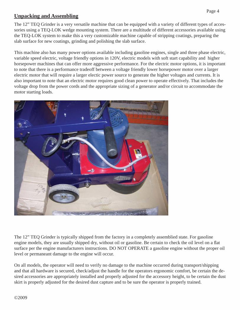
Unpacking and AssemblingThe 12” TEQ Grinder is a very versatile machine that can be equipped with a variety of different types of acces-sories using a TEQ-LOK wedge mounting system. There are a multitude of different accessories available using the TEQ-LOK system to make this a very customizable machine capable of stripping coatings, preparing the slab surface for new coatings, grinding and polishing the slab surface.
This machine also has many power options available including gasoline engines, single and three phase electric, variable speed electric, voltage friendly options in 120V, electric models with soft start capability and higher horsepower machines that can offer more aggressive performance. For the electric motor options, it is important to note that there is a performance tradeoff between a voltage friendly lower horsepower motor over a larger electric motor that will require a larger electic power source to generate the higher voltages and currents. It is also important to note that an electric motor requires good clean power to operate effectively. That includes the voltage drop from the power cords and the appropriate sizing of a generator and/or circuit to accommodate the motor starting loads.
The 12” TEQ Grinder is typically shipped from the factory in a completely assemblied state. For gasoline engine models, they are usually shipped dry, without oil or gasoline. Be certain to check the oil level on a fl at surface per the engine manufacturers instructions. DO NOT OPERATE a gasoline engine without the proper oil level or permaneant damage to the engine will occur.
On all models, the operator will need to verify no damage to the machine occurred during transport/shipping and that all hardware is secured, check/adjust the handle for the operators ergonomic comfort, be certain the de-sired accessories are appropriately installed and properly adjusted for the accessory height, to be certain the dust skirt is properly adjusted for the desired dust capture and to be sure the operator is properly trained.
Page 5
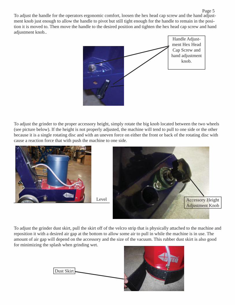
Handle Adjust-ment Hex Head Cap Screw and
hand adjustment knob.
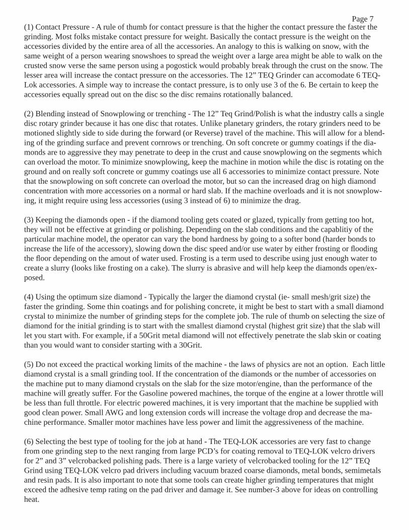
Dust Skirt
To adjust the handle for the operators ergonomic comfort, loosen the hex head cap screw and the hand adjust-ment knob just enough to allow the handle to pivot but still tight enough for the handle to remain in the posi-tion it is moved to. Then move the handle to the desired position and tighten the hex head cap screw and hand adjustment knob..
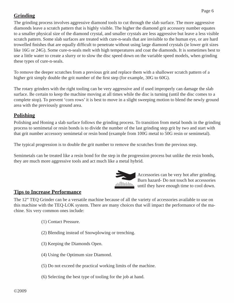
To adjust the grinder to the proper accessory height, simply rotate the big knob located between the two wheels (see picture below). If the height is not properly adjusted, the machine will tend to pull to one side or the other because it is a single rotating disc and with an uneven force on either the front or back of the rotating disc with cause a reaction force that with push the machine to one side.
To adjust the grinder dust skirt, pull the skirt off of the velcro strip that is physically attached to the machine and reposition it with a desired air gap at the bottom to allow some air to pull in while the machine is in use. The amount of air gap will depend on the accessory and the size of the vacuum. This rubber dust skirt is also good for minimizing the splash when grinding wet.
Level Accessory Height Adjustment Knob
Page 6
©2009
Accessories can be very hot after grinding. Burn hazard- Do not touch hot accessories until they have enough time to cool down.
GrindingThe grinding process involves aggressive diamond tools to cut through the slab surface. The more aggressive diamonds leave a scratch pattern that is highly visible. The higher the diamond grit accessory number equates to a smaller physical size of the diamond crystal, and smaller crystals are less aggressive but leave a less visible scratch pattern. Some slab surfaces are treated with cure-n-seals that are invisible to the human eye, or are hard trowelled fi nishes that are equally diffi cult to penetrate without using large diamond crystals (ie lower grit sizes like 16G or 24G). Some cure-n-seals melt with high temperatures and coat the diamonds. It is sometimes best to use a little water to create a slurry or to slow the disc speed down on the variable speed models, when grinding these types of cure-n-seals.
To remove the deeper scratches from a previous grit and replace them with a shallower scratch pattern of a higher grit simply double the grit number of the fi rst step (for example, 30G to 60G).
The rotary grinders with the right tooling can be very aggressive and if used improperly can damage the slab surface. Be certain to keep the machine moving at all times while the disc is turning (until the disc comes to a complete stop). To prevent ‘corn rows’ it is best to move in a slight sweeping motion to blend the newly ground area with the previously ground area.
Polishing and Honing a slab surface follows the grinding process. To transition from metal bonds in the grinding process to semimetal or resin bonds is to divide the number of the last grinding step grit by two and start with that grit number accessory semimetal or resin bond (example from 100G metal to 50G resin or semimetal).
The typical progression is to double the grit number to remove the scratches from the previous step.
Semimetals can be treated like a resin bond for the step in the progression process but unlike the resin bonds, they are much more aggressive tools and act much like a metal hybrid.
Polishing
Tips to Increase PerformanceThe 12” TEQ Grinder can be a versatile machine because of all the variety of accessories available to use on this machine with the TEQ-LOK system. There are many choices that will impact the performance of the ma-chine. Six very common ones include: (1) Contact Pressure.
(2) Blending instead of Snowplowing or trenching.
(3) Keeping the Diamonds Open.
(4) Using the Optimum size Diamond.
(5) Do not exceed the practical working limits of the machine.
(6) Selecting the best type of tooling for the job at hand.
Page 7(1) Contact Pressure - A rule of thumb for contact pressure is that the higher the contact pressure the faster the grinding. Most folks mistake contact pressure for weight. Basically the contact pressure is the weight on the accessories divided by the entire area of all the accessories. An analogy to this is walking on snow, with the same weight of a person wearing snowshoes to spread the weight over a large area might be able to walk on the crusted snow verse the same person using a pogostick would probably break through the crust on the snow. The lesser area will increase the contact pressure on the accessories. The 12” TEQ Grinder can accomodate 6 TEQ-Lok accessories. A simple way to increase the contact pressure, is to only use 3 of the 6. Be certain to keep the accessories equally spread out on the disc so the disc remains rotationally balanced.
(2) Blending instead of Snowplowing or trenching - The 12” Teq Grind/Polish is what the industry calls a single disc rotary grinder because it has one disc that rotates. Unlike planetary grinders, the rotary grinders need to be motioned slightly side to side during the forward (or Reverse) travel of the machine. This will allow for a blend-ing of the grinding surface and prevent cornrows or trenching. On soft concrete or gummy coatings if the dia-monds are to aggressive they may penetrate to deep in the crust and cause snowplowing on the segments which can overload the motor. To minimize snowplowing, keep the machine in motion while the disc is rotating on the ground and on really soft concrete or gummy coatings use all 6 accessories to minimize contact pressure. Note that the snowplowing on soft concrete can overload the motor, but so can the increased drag on high diamond concentration with more accessories on a normal or hard slab. If the machine overloads and it is not snowplow-ing, it might require using less accessories (using 3 instead of 6) to minimize the drag.
(3) Keeping the diamonds open - if the diamond tooling gets coated or glazed, typically from getting too hot, they will not be effective at grinding or polishing. Depending on the slab conditions and the capablitiy of the particular machine model, the operator can vary the bond hardness by going to a softer bond (harder bonds to increase the life of the accessory), slowing down the disc speed and/or use water by either frosting or fl ooding the fl oor depending on the amout of water used. Frosting is a term used to describe using just enough water to create a slurry (looks like frosting on a cake). The slurry is abrasive and will help keep the diamonds open/ex-posed.
(4) Using the optimum size diamond - Typically the larger the diamond crystal (ie- small mesh/grit size) the faster the grinding. Some thin coatings and for polishing concrete, it might be best to start with a small diamond crystal to minimize the number of grinding steps for the complete job. The rule of thumb on selecting the size of diamond for the initial grinding is to start with the smallest diamond crystal (highest grit size) that the slab will let you start with. For example, if a 50Grit metal diamond will not effectively penetrate the slab skin or coating than you would want to consider starting with a 30Grit.
(5) Do not exceed the practical working limits of the machine - the laws of physics are not an option. Each little diamond crystal is a small grinding tool. If the concentration of the diamonds or the number of accessories on the machine put to many diamond crystals on the slab for the size motor/engine, than the performance of the machine will greatly suffer. For the Gasoline powered machines, the torque of the engine at a lower throttle will be less than full throttle. For electric powered machines, it is very important that the machine be supplied with good clean power. Small AWG and long extension cords will increase the voltage drop and decrease the ma-chine performance. Smaller motor machines have less power and limit the aggressiveness of the machine.
(6) Selecting the best type of tooling for the job at hand - The TEQ-LOK accessories are very fast to change from one grinding step to the next ranging from large PCD’s for coating removal to TEQ-LOK velcro drivers for 2” and 3” velcrobacked polishing pads. There is a large variety of velcrobacked tooling for the 12” TEQ Grind using TEQ-LOK velcro pad drivers including vacuum brazed coarse diamonds, metal bonds, semimetals and resin pads. It is also important to note that some tools can create higher grinding temperatures that might exceed the adhesive temp rating on the pad driver and damage it. See number-3 above for ideas on controlling heat.
Page 8
©2009
Gasoline EngineModelsDo not operate gasoline powered equipment without adequate ventilation. Carbon monoxide is an invisible, odorless gas that can cause death if inhaled.
Never leave the engine running unattended.
Electric Motor ModelsThe single phase electric motor models include a 2 HP induction motor (model G00010) that is standard fac-tory wired for 120V service and can be wired at the factory by request for 220V service using the appropriate NEMA plug for the correct voltage. Consult the factory for the details to match the connector the the plug pro-vided by the machine. The model G00023 is a 5 HP single phase induction motor wired for 220V, Both of these machines require a dedicated 20A outlet that is properly grounded. They are supplied with an extension cord at-tached to the machine and additional cords should not be used unless they are properly sized for the application by a qualifi ed electrical service technician or electrician to be certain the machine is supplied with an adequate power to prevent damage to the motor and/or switch.
If using a generator power source, be certain it is properly sized for the motor with enough startup capacity to prevent damage to the motor.
The Variable Speed models, G00037 and G00042 use a motor speed controller that has a forward and reverse switch (some accessories like PCD’s are directional) with a neutral between the settings. Do not change direc-tions while the disc is spinning. To start the machine, select the rotation direction (forward/Reverse), turn the speed control to desired disc speed and toggle the start/stop switch to start (the start is a momentary action switch to start the disc and settles to the on position). To stop the machine, simply toggle the start/stop switch to stop.
Read the Engine Operators Manual to familiarize yourself with the Engine controls.
Be certain the electrical service to the machine is properly grounded.
The branch circuit must have overcurrent protection appropriately sized to prevent the branch circuit from over-heating and causing an electrical fi re.
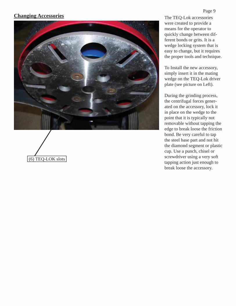
Page 9Changing Accessories The TEQ-Lok accessories
were created to provide a means for the operator to quickly change between dif-ferent bonds or grits. It is a wedge locking system that is easy to change, but it requires the proper tools and technique.
To Install the new accessory, simply insert it in the mating wedge on the TEQ-Lok driver plate (see picture on Left).
During the grinding process, the centrifugal forces gener-ated on the accessory, lock it in place on the wedge to the point that it is typically not removable without tapping the edge to break loose the friction bond. Be very careful to tap the steel base part and not hit the diamond segment or plastic cup. Use a punch, chisel or screwdriver using a very soft tapping action just enough to break loose the accessory.
(6) TEQ-LOK slots
Page 10
©2009
Grinding/cutting/drilling of masonry, concrete, metal and other materials can gen-erate dust, mists and fumes containing chemicals known to cause serious or fatal injury or illness, such as respiratory disease, cancer, birth defects or other repro-ductive harm. If you are unfamiliar with the risks associated with the particular process and/or material being cut or the composition of the tool being used, review the material safety data sheets and/or consult your employer, the manufacturers/suppliers, governmental agencies such as OSHA and NIOSH and other sources on hazardous materials. California and some other authorities, for instance, have published lists of substances known to cause cancer, reproductive toxicity, or other harmful effects.
Control dust, mist and fumes at the source where possible. In this regard, use good work practices and follow the recommendations of the manufacturers/suppliers, OSHA/NIOSH, and occupational and trade associations. Water should be used for dust suppression when wet cutting is feasible. When the hazards from inhalation of dust, mists and fumes cannot be eliminated, the operator and any bystanders should always wear a respirator approved by NIOSH/MSHA for the materials be-ing used.
Grinding/cutting/drilling of masonry, concrete and other materials with silica in their composition may give off dust or mists containing crystalline silica. Silica is a basic component of sand, quartz, brick clay, granite and numerous other minerals and rocks. Repeated and/or substantial inhalation of airborne crystalline silica can cause serious or fatal respiratory diseases, including silicosis. In addition, Califor-nia and some other authorities have listed respirable crystalline silica as a substance known to cause cancer. When cutting such materials, always follow the respiratory precautions mentioned above.
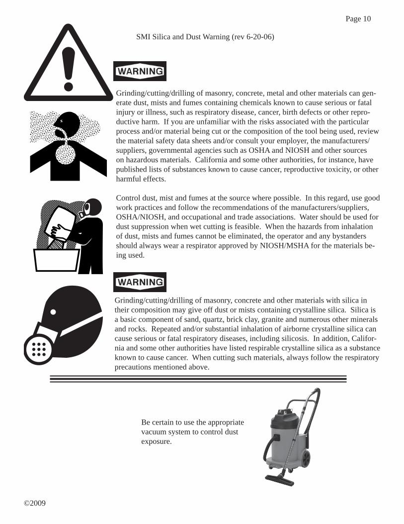
SMI Silica and Dust Warning (rev 6-20-06)
Be certain to use the appropriate vacuum system to control dust exposure.
Page 11
All machine adjustments and maintenance must be performed only when the machine is turned off and the powercord completely disconnected following the LOTO (Lockout-Tagout) procedures.
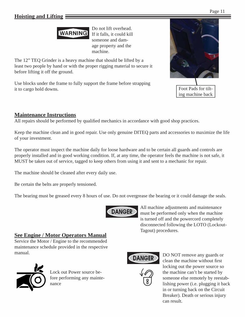
Hoisting and Lifting
Do not lift overhead. If it falls, it could kill someone and dam-age property and the machine.
The 12” TEQ Grinder is a heavy machine that should be lifted by a least two people by hand or with the proper rigging material to secure it before lifting it off the ground.
Use blocks under the frame to fully support the frame before strapping it to cargo hold downs.
Maintenance InstructionsAll repairs should be performed by qualifi ed mechanics in accordance with good shop practices.
Keep the machine clean and in good repair. Use only genuine DITEQ parts and accessories to maximize the life of your investment.
The operator must inspect the machine daily for loose hardware and to be certain all guards and controls are properly installed and in good working condition. If, at any time, the operator feels the machine is not safe, it MUST be taken out of service, tagged to keep others from using it and sent to a mechanic for repair.
The machine should be cleaned after every daily use.
Be certain the belts are properly tensioned.
The bearing must be greased every 8 hours of use. Do not overgrease the bearing or it could damage the seals.
DO NOT remove any guards or clean the machine without fi rst locking out the power source so the machine can’t be started by someone else remotely by reestab-lishing power (i.e. plugging it back in or turning back on the Circuit Breaker). Death or serious injury can result.
See Engine / Motor Operators ManualService the Motor / Engine to the recommended maintenance schedule provided in the respective manual.
Lock out Power source be-fore performing any mainte-nance
Foot Pads for tilt-ing machine back
Page 12
©2009
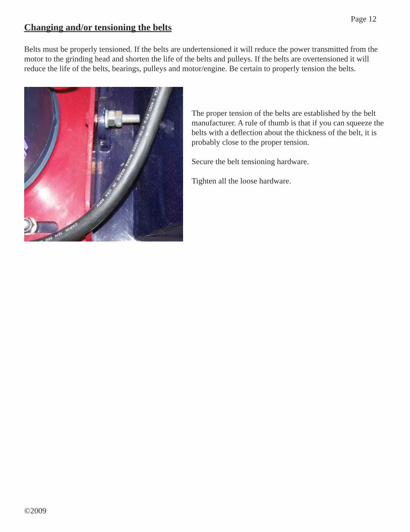
Changing and/or tensioning the belts
Belts must be properly tensioned. If the belts are undertensioned it will reduce the power transmitted from the motor to the grinding head and shorten the life of the belts and pulleys. If the belts are overtensioned it will reduce the life of the belts, bearings, pulleys and motor/engine. Be certain to properly tension the belts.
The proper tension of the belts are established by the belt manufacturer. A rule of thumb is that if you can squeeze the belts with a defl ection about the thickness of the belt, it is probably close to the proper tension.
Secure the belt tensioning hardware.
Tighten all the loose hardware.
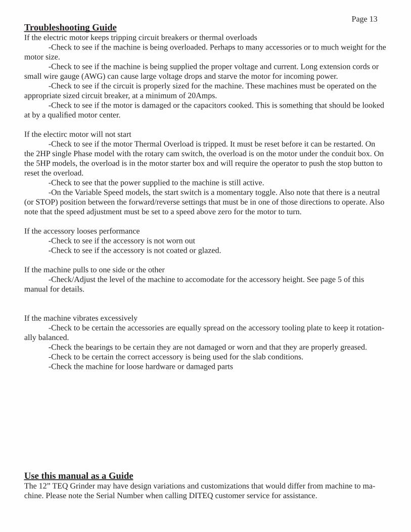
Page 13Troubleshooting GuideIf the electric motor keeps tripping circuit breakers or thermal overloads -Check to see if the machine is being overloaded. Perhaps to many accessories or to much weight for the motor size. -Check to see if the machine is being supplied the proper voltage and current. Long extension cords or small wire gauge (AWG) can cause large voltage drops and starve the motor for incoming power. -Check to see if the circuit is properly sized for the machine. These machines must be operated on the appropriate sized circuit breaker, at a minimum of 20Amps. -Check to see if the motor is damaged or the capacitors cooked. This is something that should be looked at by a qualifi ed motor center.
If the electirc motor will not start -Check to see if the motor Thermal Overload is tripped. It must be reset before it can be restarted. On the 2HP single Phase model with the rotary cam switch, the overload is on the motor under the conduit box. On the 5HP models, the overload is in the motor starter box and will require the operator to push the stop button to reset the overload. -Check to see that the power supplied to the machine is still active. -On the Variable Speed models, the start switch is a momentary toggle. Also note that there is a neutral (or STOP) position between the forward/reverse settings that must be in one of those directions to operate. Also note that the speed adjustment must be set to a speed above zero for the motor to turn.
If the accessory looses performance -Check to see if the accessory is not worn out -Check to see if the accessory is not coated or glazed.
If the machine pulls to one side or the other -Check/Adjust the level of the machine to accomodate for the accessory height. See page 5 of this manual for details.
If the machine vibrates excessively -Check to be certain the accessories are equally spread on the accessory tooling plate to keep it rotation-ally balanced. -Check the bearings to be certain they are not damaged or worn and that they are properly greased. -Check to be certain the correct accessory is being used for the slab conditions. -Check the machine for loose hardware or damaged parts
Use this manual as a GuideThe 12” TEQ Grinder may have design variations and customizations that would differ from machine to ma-chine. Please note the Serial Number when calling DITEQ customer service for assistance.
Page 14
©2009
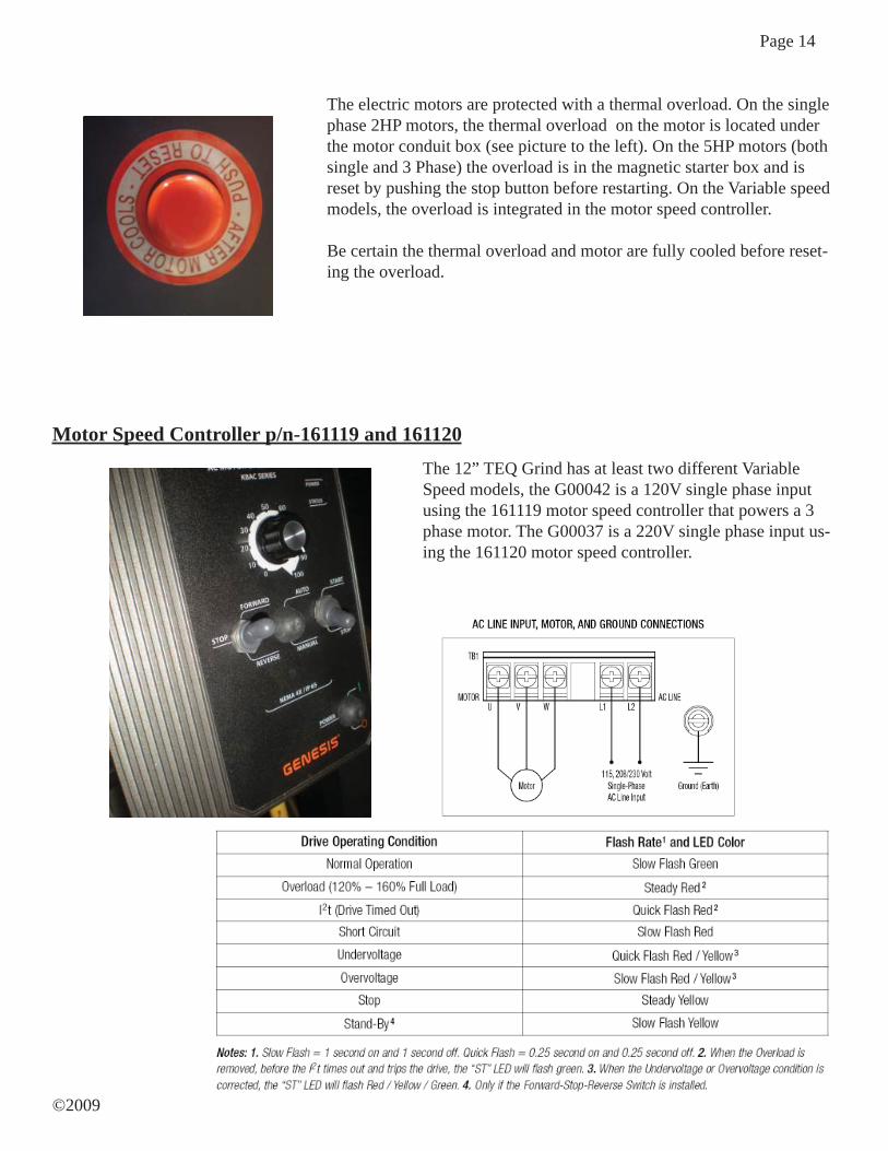
Motor Speed Controller p/n-161119 and 161120The 12” TEQ Grind has at least two different Variable Speed models, the G00042 is a 120V single phase input using the 161119 motor speed controller that powers a 3 phase motor. The G00037 is a 220V single phase input us-ing the 161120 motor speed controller.
The electric motors are protected with a thermal overload. On the single phase 2HP motors, the thermal overload on the motor is located under the motor conduit box (see picture to the left). On the 5HP motors (both single and 3 Phase) the overload is in the magnetic starter box and is reset by pushing the stop button before restarting. On the Variable speed models, the overload is integrated in the motor speed controller.
Be certain the thermal overload and motor are fully cooled before reset-ing the overload.
Page 15
6/8/2009 12:40:57 PM
6/28/2007 5:11:39 PM -
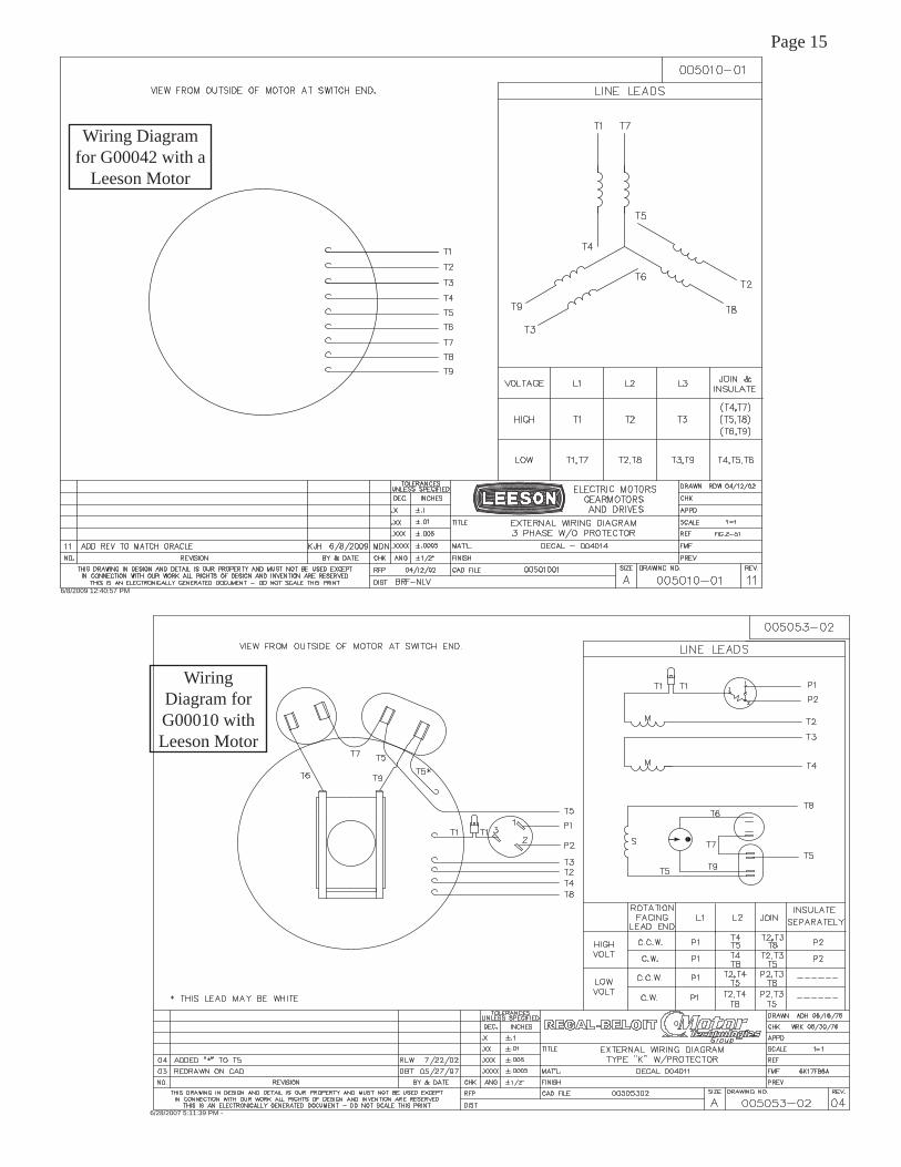
Wiring Diagram for G00010 with Leeson Motor
Wiring Diagram for G00042 with a
Leeson Motor
Page 16
©2009

Page 17

Page 18
©2009
GENERAL PROVISIONS – The warranties de-scribed below are provided by DITEQ Corporation (“DITEQ”) to the original purchasers of new DITEQ Equipment from DITEQ or authorized DITEQ deal-ers. Under these warranties, DITEQ will repair or replace, at its option, any covered part which is found to be defective in material or workmanship during the applicable warranty term. Warranty service must be performed by DITEQ or a dealer or service center authorized by DITEQ to sell and/or service the type of product involved, which will use only new or remanu-factured parts or components furnished by DITEQ. Warranty service will be performed without charge to the purchaser for parts or labor. The purchaser will be responsible, however for any service call and/or transportation and/or freight of product to and from DITEQ’s, the dealer’s or service center’s place of business, for any premium charged for overtime labor requested by the purchaser, and for any service and/ormaintenance not directly related to any defect covered under the warranties below.
WHAT IS WARRANTED – All parts of any new DITEQ Equipment are warranted for the number ofmonths specifi ed below. Component manufacturers offer separate warranties and warranty terms as stated below. Warranty statements required by law cover-ing engine emission-related parts and components are found in the engine operating manual delivered with the machine. Each warranty term begins on the date of product delivery to the purchaser.
TEQ Grind 12 MonthsBaldor Motors 12 MonthsLeeson Motors 12 MonthsSubaru Robin Engines 24 MonthsHonda Engines 12 Months
WHAT IS NOT WARRANTED – DITEQ IS NOT RESPONSIBLE FOR THE FOLLOWING:(1) Used products; (2) Any product that has been modifi ed in ways not approved by DITEQ; (3) De-preciation or damage caused by normal wear, lack of reasonable and proper maintenance, failure to follow operating instructions, misuse, lack of proper pro-tection during storage, transporting or accident; (4) Normal maintenance parts and service.
SECURING WARRANTY SERVICE – To secure warranty service, the purchaser must (1) report theProduct defect to DITEQ, an authorized dealer or an authorized service center and request repair within the applicable warranty term, (2) present evidence of the warranty start date, and (3) make the product available to DITEQ, the dealer or service center within a rea-sonable period of time.
LIMITATIONS OF IMPLIED WARRANTIES AND OTHER REMEDIES – To the extent permitted by law, neither DITEQ nor any company affi liated with it makes any warranties, representations or promisesas to the quality, performance or freedom from defect of the equipment covered by this warranty.
IMPLIED WARRANTIES OF MERCHANTABIL-ITY AND FITNESS FOR A PARTICULAR PUR-POSE, TO THE EXTENT APPLICABLE, SHALL BE LIMITED IN DURATION TO THE APPLI-CABLE PERIOD OF WARRANTY SET FORTH ON THIS PAGE. THE PURCHASER’S ONLY REM-EDIES IN CONNECTION WITH THE BREACH OR PERFORMANCE OF ANY WARRANTY ON THE DITEQ EQUIPMENT ARE THOSE SET FORTH ON THIS PAGE. IN NO EVENT WILL THE DEALER, DITEQ OR ANY COMPANY AFFILIATED WITH DITEQ BE LIABLE FOR INCIDENTAL OR CON-SEQUENTIAL DAMAGES. (Note: Some states do not allow limitations on how long an implied warranty lasts or the exclusion or limitation of incidental or consequential damages so the above limitations and exclusions may not apply to you.) This warranty gives you specifi c legal rights, and you may also have other rights which vary from state to state.
NO DEALER WARRANTY- THE SELLING DEAL-ER MAKES NO WARRANTY OF ITS OWN AND THE DEALER HAS NO AUTHORITY TO MAKE ANY REPRESENTATION OR PROMISE ON BE-HALF OF DITEQ, OR TO MODIFY THE TERMS OR LIMITATIONS OF THIS WARRANTY IN ANY WAY.
If further information is desired, contact DITEQ.
DITEQ Corporation1250 NW Main Street, Lee’s Summit MO 64086
LIMITED WARRANTY FOR NEW DITEQ EQUIPMENT