Embed Size (px)
Citation preview

OPERATOR’S & PARTS MANUAL
MODEL 780 Piler
PART # 290239

Mission Statement Our mission is to consistently provide high quality, reliable, safe, and well-designed
products and services to meet and exceed the needs of our customers.
Service Centers
Phone: (208) 785-0480
E-Mail: [email protected]
Web Site: www.spudnik.com
BLACKFOOT 584 West 100 North P.O. Box 1045 Blackfoot, ID 83221 Phone (208) 785-0480
HEYBURN 300 Centennial Dr. Heyburn, ID 83336 Phone (208) 436-8052 Fax (208) 495-9170
GRAFTON 1410 12th St. West Grafton, ND 58273 Phone (701) 352-9603 Fax (701) 352-9610
PRESQUE ISLE 80B Airport Drive Presque Isle, ME 04769 Phone (207) 764-4686 Fax (207) 764-4674
Table Of Contents
Description Page #
Introduction ………………………………………………………………………... Forward to Operating Manual …………………………………………………… Warranty …………………………………………………………………………... General ……………………….…………………………………………….……... Product Characteristics ………………………………………………………….. Dangers, operating errors and exemption from liability .……………………… Safety ….…………………………………………………………………….…….. General safety and accident prevention regulations …………………………. Special safety instructions .……………………………………………………… Towed machines …………………………………………………………………. Electrical system, electronics …………………………………………………… Hydraulic system .…………………………………………..……………………. Warning symbols and other instruction notices on the machine ..………….. Configuration and functions of the machine ……………………………….….. Remote ……………………………………………………………………………. Remote Troubleshooting ………………………………………………………... Maintenance ……………………………………………………………………… General Safety ……………………………………………………………………. Special Safety Instructions ……………………………………………………… Spare Parts Procurement ……………………………………………………….. Disposing of Spare Parts ………………………………………………………... Cleaning After …………………………………………………………………….. Parts to Be Cleaned ……………………………………………………………… Storage ……………………………………………………………………………. Shortening/Repairing the Main Webs ………………………………………….. Screwed Connections …………………………………………………………… Main Web Connecting Pieces …………………………………………………... Drawbar Eye for Hitch and Piton Fix Couplings ………………………………. Chassis…………………………………………………………………………….. Tires ……………………………………………………………………………….. Mechanical Drives ……………………………………………………………….. Chain Drives ……………………………………………………………………… Belt Drives ………………………………………………………………………... Lubrication ………………………………………………………………………... Hydraulic System ………………………………………………………………… Electrical System ………………………………………………………………… Braking System ………………………………………………………………….. Machine Parts Breakdown ……………………………………………………...
3 4 5 6 7 8 9
10 11-13
11 12 13
14-15 16
17-20 21-27 28-47 28-29
30 31 31 32 33 34
35-37 38 39 39 40 40 41 42 43 44 45 46 47 48
Operator's Manual Model 780
Page 2
Introduction
Welcome to the SPUDNIK line of potato handling equipment. We appreciate your decision to make our equipment a part of your operation, and look forward to a long term partnership. We strive to put the best quality and workmanship into each of our machines, and hope as you use you’re MODEL 780 Piler, that you will find this to be true. This owner’s/operator’s manual has been prepared to aid you in the safe operation and service of your Piler.
Read this manual carefully to learn how to operate your machine safely and within the designed limits of this machine. Failure to do so could result in personal injury and/or damage to the machine
This manual is considered to be an important part of this machine and should accompany it when moved from location to location
Warranty is provided as, part of the SPUDNIK EQUIPMENT COMPANY LLC service program, for cus-tomers who operate and maintain their equipment as outlined in this manual.
OWNER REGISTRATION
Name
Address
City
State / Province
Country
Model Number Serial Number
Purchase Date
Operator's Manual Model 780
Page 3
Foreword to the Operating Manual
This operating manual is intended to familiarize the user with the 780 Piler and its designated use.
This operating manual contains important information on how to operate the machine safely, properly and efficiently. Observing the instructions in this manual will help to avoid dangers, reduce repair costs and down-times, and to increase the reliability and service life of the machine. Please also take note of the section “Dangers, operating errors and exceptions form liability.”
This manual is to be supplemented by the respective national rules and regulations concerning accident prevention and environmental protection.
The operating manual must always be available whenever the machine is in use.
This operating manual must be read and applied by all persons involved with the machine, such as:
Operation, including setting up, troubleshooting during operations, care, disposal of fuels and consumables
Maintenance (servicing, inspection, repair), and/or
Transport
In addition to this operating manual and the relevant mandatory rules and regulations concerning accident prevention and environmental protection of the country or region in which the machine is being used, the generally recognized technical rules for safe and proper working must also be observed.
Operator's Manual Model 780
Page 4
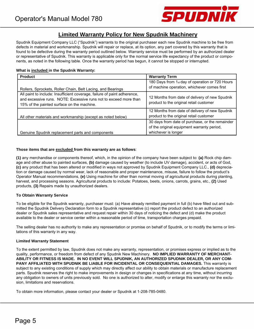
Limited Warranty Policy for New Spudnik Machinery Spudnik Equipment Company LLC (“Spudnik”) warrants to the original purchaser each new Spudnik machine to be free from defects in material and workmanship. Spudnik will repair or replace, at its option, any part covered by this warranty that is found to be defective during the warranty period outlined below. Warranty service must be performed by an authorized dealer or representative of Spudnik. This warranty is applicable only for the normal service life expectancy of the product or compo-nents, as noted in the following table. Once the warranty period has begun, it cannot be stopped or interrupted.
What is included in the Spudnik Warranty:
Those items that are excluded from this warranty are as follows:
(1) any merchandise or components thereof, which, in the opinion of the company have been subject to: (a) Rock chip dam-age and other abuse to painted surfaces, (b) damage caused by weather (to include UV damage), accident, or acts of God, (c) any product that has been altered or modified in ways not approved by Spudnik Equipment Company LLC., (d) deprecia-tion or damage caused by normal wear, lack of reasonable and proper maintenance, misuse, failure to follow the product’s Operator Manual recommendations, (e) Using machine for other than normal moving of agricultural products during planting, harvest, and processing seasons. Agricultural products to include: Potatoes, beets, onions, carrots, grains, etc., (2) Used products, (3) Repairs made by unauthorized dealers.
To Obtain Warranty Service
To be eligible for the Spudnik warranty, purchaser must: (a) Have already remitted payment in full (b) have filled out and sub-mitted the Spudnik Delivery Declaration form to a Spudnik representative (c) report the product defect to an authorized dealer or Spudnik sales representative and request repair within 30 days of noticing the defect and (d) make the product available to the dealer or service center within a reasonable period of time, transportation charges prepaid.
The selling dealer has no authority to make any representation or promise on behalf of Spudnik, or to modify the terms or limi-tations of this warranty in any way.
Limited Warranty Statement
To the extent permitted by law, Spudnik does not make any warranty, representation, or promises express or implied as to the quality, performance, or freedom from defect of any Spudnik New Machinery. NO IMPLIED WARRANTY OF MERCHANT-ABILITY OR FITNESS IS MADE. IN NO EVENT WILL SPUDNIK, AN AUTHORIZED SPUDNIK DEALER, OR ANY COM-PANY AFFILIATED WITH SPUDNIK BE LIABLE FOR INCIDENTAL OR CONSEQUENTIAL DAMAGES. This warranty is subject to any existing conditions of supply which may directly affect our ability to obtain materials or manufacture replacement parts. Spudnik reserves the right to make improvements in design or changes in specifications at any time, without incurring any obligation to owners of units previously sold. No one is authorized to alter, modify or enlarge this warranty nor the exclu-sion, limitations and reservations.
To obtain more information, please contact your dealer or Spudnik at 1-208-785-0480.
Product Warranty Term
Rollers, Sprockets, Roller Chain, Belt Lacing, and Bearings 180 Days from 1st day of operation or 720 Hours of machine operation, whichever comes first
All paint to include: Insufficient coverage, failure of paint adherence, and excessive runs. NOTE: Excessive runs not to exceed more than 15% of the painted surface on the machine.
12 Months from date of delivery of new Spudnik product to the original retail customer
All other materials and workmanship (except as noted below) 12 Months from date of delivery of new Spudnik product to the original retail customer
Genuine Spudnik replacement parts and components
30 days from date of purchase, or the remainder of the original equipment warranty period, whichever is longer
Operator's Manual Model 780
Page 5

General
Designated use of the machine:
The 780 piler is designed exclusively for normal agricultural operations (designated use).
Using the machine for other purposes or exceeding its designated limits shall be considered as being contrary to the designated use. The manufacturer shall not be liable for any damages caused as a result of such use. The user shall be solely responsible for such risks.
Operating the machine in accordance with its designated use also includes observing the instructions specified in the operating manual and complying with the inspection and maintenance directives.
The piler may only be operated, serviced and repaired by persons who are familiar with the piler and have been informed of the possible dangers.
In order to prevent dangerous situations. The information contained in this operating manual must be read and observed by all persons who operate, service or check this machine. Particular attention should be paid to the section entitled “Safety”. Any instructions which are not understood must be clari-fied before initial operation of the machine. In such cases, please consult your SPUDNIK agent or con-tact us directly.
The relevant accident prevention directives as well as other, generally applicable safety, health and road traffic regulations are to be observed.
Unauthorized modifications and the use of spare parts, accessories and ancillary equipment not sup-plied and/or not approved by SPUDNIK, as manufacturer, can have detrimental effects on the construc-tion of the machine or on its functions and hence impair the machine’s active and/or passive driving and operations safety (accident prevention). The manufacturer does not accept liability for any damage re-sulting from this.
Technical data, dimensions and weights are not binding, we reserve the right to make modification in the course of further engineering developments; errors excepted.
In the direction of product flow.
Operator's Manual Model 780
Page 6
Product Characteristics
Manufacturer’s address
SPUDNIK EQUIPMENT COMPANY LLC
584 W 100 N
PO Box 1045
Blackfoot, ID 83221
Phone: (208) 785-0480
Fax: (208) 785-1497
www.spudnik.com
E-mail: [email protected]
Advice concerning inquiries and orders
Please quote the type designation and the machine number when ordering accessories and spare parts.
The use of spare parts supplied by third parties shall only be permitted after consultation with the manufacture. Original spare parts and accessories approved by the manufacturer are a contribution to safety. The use of other parts may invalidate the liability of the manufacturer for any conse-quences arising out of such use.
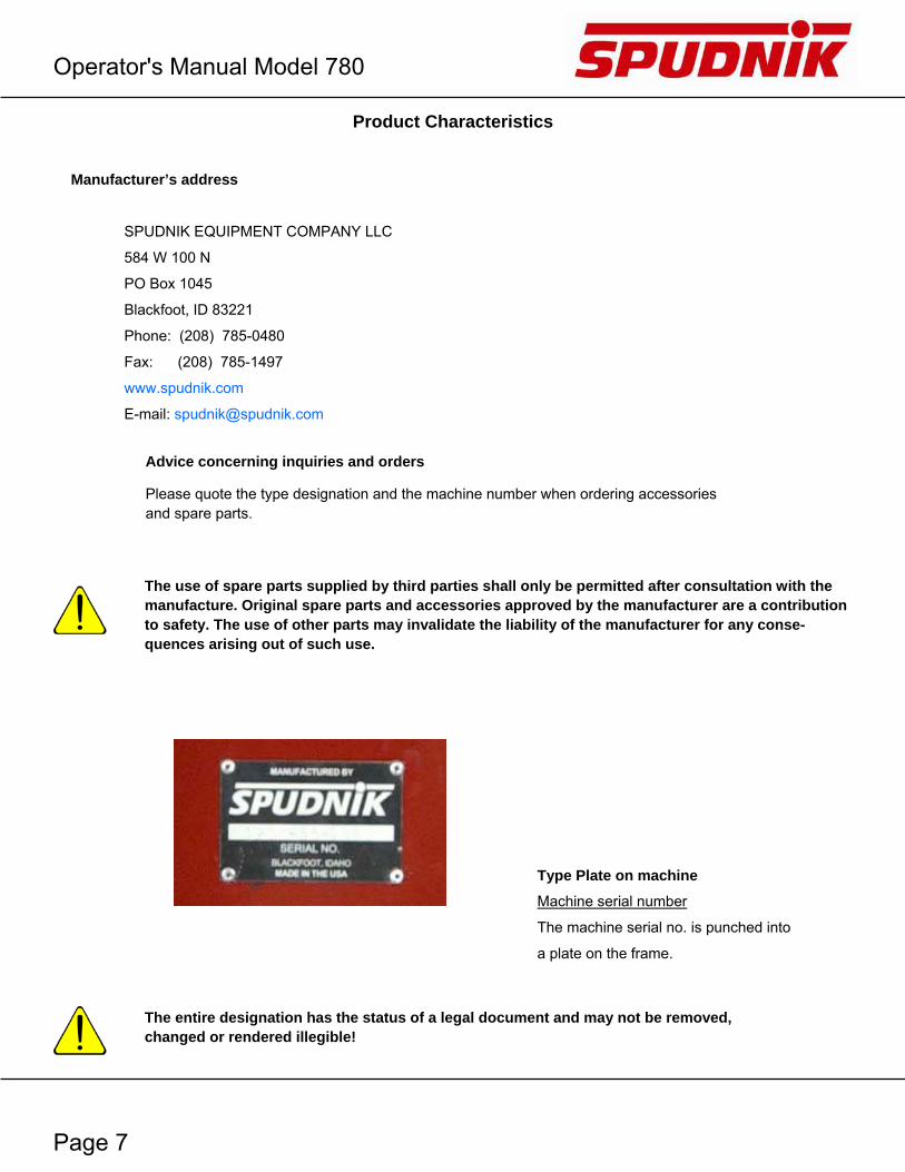
Type Plate on machine
Machine serial number
The machine serial no. is punched into
a plate on the frame.
The entire designation has the status of a legal document and may not be removed, changed or rendered illegible!
Operator's Manual Model 780
Page 7
Dangers, operating errors and exemption from liability
1. No responsibility will be accepted for possible dangers arising from operating the machine in a way which does not comply with its designated use.
2. Damage to agricultural produce particularly vulnerable to damage during processing cannot be en-tirely ruled out. Weather conditions, the quality of the produce and many other circumstance beyond our or the operators control have an influence on the vulnerability to damage the produce being processed. For example, when processing the submerged weight, the manuring (nitrogen content), the degree of maturity (firmness of the skin), the temperatures during processing and many other circumstances can have an influence on the vulnerability to damage. The examples do not claim to be exhaustive.
3. To avoid damage to agricultural produce the user must adapt the machine to the respective operat-ing conditions. The results produced by the machine must be constantly monitored and checked.
4. SPUDNIK shall not be liable for any damage to agricultural produce and other items which occurs as a result of operating and adjustment errors or others incorrect usage.
5. SPUDNIK accepts no liability for any damage caused as a result of operators not complying with the designate use of the machine. This also applies to damage to agricultural produce which, because of certain external influences, cannot be avoided with the current state of the art.
Operator's Manual Model 780
Page 8

Text marked with this symbol alerts you to possible accident and injury hazards; hazards to machinery; practical applications, settings or functions; or environmental protection measures.
Qualification and training of personnel
Any work on or with the machine may only be performed by reliable personnel. Statutory minimum age limits must be ob-served.
Employ only trained or instructed staff; the individual responsibilities of the personnel for operation setting-up, maintenance and repair must be clearly established.
Make sure that only authorized personnel work on or with the machine.
Define the machine operator’s responsibilities — also with regard to observing traffic regulation. The operator must have the authority to refuse any instructions issued by third parties which contravene safety!
Persons requiring training or instruction and those in a general training course, should not be allowed to work on with the machine unless they are under the constant supervision of an experienced person.
Work on the machine’s electrical system may only be carried out by an electrician or by persons working under the super-vision and guidance of an electrician; all such work must be carried out in accordance with electrical engineering regula-tions.
Work on the wheels, braking and steering systems may only be performed by specially trained personnel.
Work on the hydraulic system may only be carried out by personnel with special knowledge and experience of hydraulics.
The use of spare parts, accessories and auxiliary equipment not supplied and/or not approved by SPUDNIK can have det-rimental effect on the construction of the SPUDNIK machine or on its functions and hence impair the active and/or passive driven and/or operational safety (accident prevention).
SPUDNIK shall not be liable for any damage cause by the use of parts, accessories and ancillary equipment not supplied and/or approved by SPUDNIK.
Conversions of or modifications to the machine may only be carried out after consultation with SPUDNIK.
Safety
This operating manual contains basic directions which should be observed during setting-up, operation and maintenance. Therefore, this operating manual absolutely must be read by the personnel concerned prior to starting up and using the machine, and must be available for them at all times. Any instructions which are not understood must be clarified before initial operation of the machine, for clarification, please consult your SUPDNIK agent or contact us directly.
All safety instructions must be observed, both the general safety instructions given here and the specific safety instructions given elsewhere in this manual.
Observe the advice contained in the operating manual as well as the generally applicable safety and accident prevention regulations!
If safety instructions are not complied with, you risk injury to yourself and others as well as damage to the environment or the machine. Non-compliance with safety instructions can also void claims for damages.
Identification of important instructions in the operating manual
Operator's Manual Model 780
Page 9

General safety and accident prevention regulations
The safety advice and information given in this operating manual, the valid nation regulations concerning accident prevention and any applicable internal employment, operational and safety regulations of the operator are to be observed.
1. Warning signs and other notices on the machine provide important information for safe operation. Observing them will serve your safety.
2. Before starting work, make yourself familiar with all the equipment and controls as well as their functions. To do so when you have already started work is too late!
3. The user should wear close-fitting clothing. Avoid loose-fitting clothing!
4. Keep the machine clean to avoid the risk of fire!
5. Check around the machine before moving off or starting up (watch out for children)! Make sure you have adequate all-around visibility.
6. Always match your speed to the local conditions! Avoid sudden turning maneuvers when driving uphill or downhill or when traveling across a slope!
7. Observe the respective regulations when using public roads!
8. Take into account the wide overhand and/or the sideways force acting on the machine when turning or negotiation curves!
9. Only start up the machine when all guards are attached and in their correct (protective) position!
10. Stay clear of the turning and pivoting areas of the machine!
11. The primary responsibility for safe operation of the Spudnik machine lies with the owner/operator.
12. OSHA (Occupational Safety and Health Administration) requires that all operators be trained at the time of initial assignment, and annually thereafter by the employer, in the safe operation of the machine.
13. Keep hands, feet, long hair, and clothing away from moving and/or rotating parts.
14. Do not attempt to service, lubricate, clean or adjust machine while it is running.
15. Inspect all mechanisms before staring the machine and replace all worn or damaged parts.
16. Replace all worn or missing bolts with SAE Grade 5 or better unless specifically stated otherwise.
Non-observance of the safety and accident prevention regulations entails the following risks:
-Endangering the operator or other nearby persons as a result of safety devices not being fitted or being in their correct (protective) position!
-Damaging important machine functions!
-Errors when carrying out maintenance or repair work!
-Endangering the operator or other nearby persons through certain mechanical or chemical peculiarities!
-Risk of pollution due to leak in the hydraulic system, fuel tank, pipes, as well as in the engine and gearbox!
Operator's Manual Model 780
Page 10
Special safety instructions
Towed machines
1. Risk of injury when hitching up or unhitching machine to/from the towing vehicle!
2. Never allow persons to stand between the tractor and the machine unless the tractor is secured against rolling away by means of the parking brake and/or wheel chocks!
3. Hitch up the machine only in accordance with the instructions and only to the prescribed compo-nents! Follow the instruction in the tractor’s manual.
4. Beware of dangerous points (risk of injury through crushing and shearing) when operating the sup-port foot!
5. Never exceed the permissible nose weight of the machine coupling!
6. Never exceed the permissible axle loads and total weight of the tractor (see vehicle documents)!
7. During transport, secure all moving parts with the retainers provided to prevent movement and hence possible accidents!
8. It is forbidden to allow persons to ride on the machine while traveling on roads!
9. Driving, steering and braking ability!
10. Before leaving the tractor, switch off the engine, remove the ignition key and secure the machine against rolling away. Use wheel chocks!
11. The design and function of intake and discharge mechanisms, e.g.webs, sifting units, chutes, means that they cannot be fully protected. Therefore, keep a safe distance from such moving parts when in operation! This advice applies to all other similar auxiliary equipment!
12. Keep clear of the discharge area!
13. Never stand or work beneath suspended loads! persons are only allowed to stand or work under suspended machines or machine parts (e.g. car elevator, discharge conveyor belt) when safety sup-ports are fitted (e.g. trestle, crane). This particularly applies to maintenance and repair work.
14. Dangerous implements are located behind safety covers. These do not necessarily come to a stand-still as soon as the drive is switched off. Therefore, keep well clear until such parts have come to a standstill! Never open safety devices such as covers, flaps, etc. while the machine is in operation! Never reach under safety devices!
15. Only carry out maintenance, repair and cleaning work on the machine when the drive is switched off and the engine is stationary! Remove the ignition key from the tractor.
16. Wear suitable protective clothing, gloves, footwear, etc. when handling sharp machines, e.g. cutting knives.
17. Keep clear of opening/hinged covers and guards!
18. Only start up the machine when all safety devices are attached and in the correct (protective) posi-tion! It is forbidden to open or remove safety devices (e.g. covers, flaps, etc.) on the machine while it is in operation!
19. Persons are not allowed to be on the machine while it is operation!
Operator's Manual Model 780
Page 11
Special safety instructions
Electrical system, electronics
Use only original fuses with the specified current rating! Switch off the machine immediately if a fault occurs in the electrical power supply.
Work on the electrical system or equipment may only be carried out by an electrician, or by specially instructed personnel under the control and supervision of an electrician, and in accordance with the ap-plicable electrical engineering regulations.
The machine’s electrical equipment is to be inspected and tested at regular intervals. Defects such as loose connection or scorched cables must be rectified immediately.
The machine is fitted with electronic components and modules, the function of which may be influenced by the electromagnetic fields of other equipment. Such interference can lead to potentially dangerous situations if the following safety advice is not observed.
If electrical or electronic devices and/or components are retrofitted to the machine then it is the responsi-bility of the user to check whether such installations interfere with the vehicle’s electronics or other com-ponents.
This particularly applies to:
-Mobile telephones,
-Radio equipment.
In particular, the following conditions must also be satisfied if mobile communications systems (e.g. ra-dio, telephone are to be installed subsequently:
-Only approved devices complying with the relevant national regulations may be installed.
-The device(s) must form a permanents installation.
-the operation of portable or mobile devices in the tractor or on the machine is only permitted via a con-nection a permanent external aerial.
-The transmitter part must be installed separately from the vehicle electronics.
-A properly installed aerial is to be fitted with a good earth connection between aerial and vehicle chas-sis.
The installation instructions of the machine manufacturer are also to be observed for the wiring and fit-ting as well as the maximum current consumption.
Operator's Manual Model 780
Page 12
Special safety instructions
Hydraulic system
1. The Hydraulic system is under high pressure!
2. Make sure that the hydraulic system is depressurized (tractor and machine) when connecting the hydraulic hoses to the tractor’s hydraulic system.
3. Hydraulic hose lines should be inspected at regular intervals and replace if damaged or worn! New hose lines must comply with the technical specification of the machine manufacturer! Hoses and hose couplings undergo a natural ageing process, even if stored and used correctly; therefore, their period of storage an use is limited. The service life of a hose may deviate from these figures if ex-perience has shown this to be the case, in particular taking account the potential danger.
4. Fluids escaping under high pressure (hydraulic oil) can penetrate the skin and cause serious inju-ries! If such injuries occur, call a doctor immediately! Risk of infection!
5. Lower the machine, depressurize the system and switch off the engine before working on the hy-draulic system!
6. Take care when working on the hydraulic system. Hot hydraulic oil can cause serious burns! Let the hydraulic system cool down beforehand and wear gloves! Collect and dispose of oild oil in accor-dance with the regulations!
Operator's Manual Model 780
Page 13
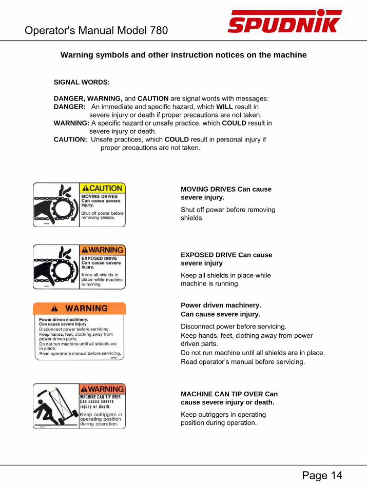
SIGNAL WORDS:
DANGER, WARNING, and CAUTION are signal words with messages:DANGER: An immediate and specific hazard, which WILL result in
severe injury or death if proper precautions are not taken.WARNING: A specific hazard or unsafe practice, which COULD result in
severe injury or death.CAUTION: Unsafe practices, which COULD result in personal injury if
proper precautions are not taken.
Warning symbols and other instruction notices on the machine
MOVING DRIVES Can cause severe injury.
Shut off power before removing shields.
EXPOSED DRIVE Can cause severe injury
Keep all shields in place while machine is running.
Power driven machinery.Can cause severe injury.
Disconnect power before servicing.Keep hands, feet, clothing away from power driven parts.Do not run machine until all shields are in place.Read operator’s manual before servicing.
MACHINE CAN TIP OVER Can cause severe injury or death.
Keep outriggers in operating position during operation.
Operator's Manual Model 780
Page 14

Warning symbols and other instruction notices on the machine
BOOM MAY MOVE WITHOUT WARNING Can cause serious injury.
Stay clear of boom at all times.Disconnect power before servicing.
Damage to machinery can occur and control of machinery and towing vehicle can be lost.Can cause severe injury or death.
Both hopper and boom braces must be in place and properly secured before towing.
UNGROUNDED MACHINE Can cause severe injury or death.
Connect to external ground per national electrical code.
MACHINE STARTS WITHOUT NOTICE Can cause severe injury.
Disconnect main power before mounting.
HIGH VOLTAGE Will cause severe injury or death.
Disconnect main power before servicing.
Operator's Manual Model 780
Page 15
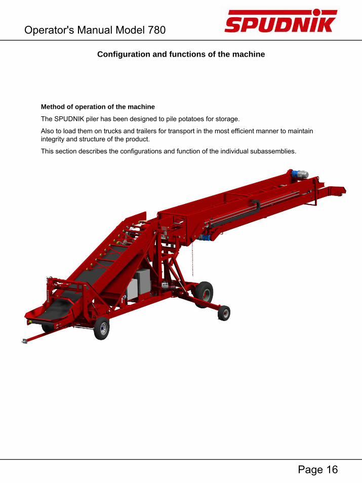
Configuration and functions of the machine
Method of operation of the machine
The SPUDNIK piler has been designed to pile potatoes for storage.
Also to load them on trucks and trailers for transport in the most efficient manner to maintain integrity and structure of the product.
This section describes the configurations and function of the individual subassemblies.
Operator's Manual Model 780
Page 16
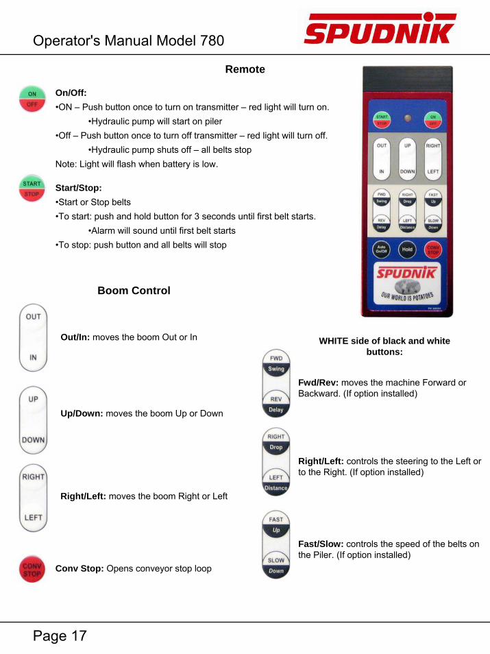
On/Off:
•ON – Push button once to turn on transmitter – red light will turn on.•Hydraulic pump will start on piler
•Off – Push button once to turn off transmitter – red light will turn off.•Hydraulic pump shuts off – all belts stop
Note: Light will flash when battery is low.
Start/Stop:
•Start or Stop belts•To start: push and hold button for 3 seconds until first belt starts.
•Alarm will sound until first belt starts•To stop: push button and all belts will stop
Out/In: moves the boom Out or In
Up/Down: moves the boom Up or Down
Right/Left: moves the boom Right or Left
Fwd/Rev: moves the machine Forward or Backward. (If option installed)
Right/Left: controls the steering to the Left or to the Right. (If option installed)
Fast/Slow: controls the speed of the belts on the Piler. (If option installed)
Conv Stop: Opens conveyor stop loop
Boom Control
WHITE side of black and white buttons:
Remote
Operator's Manual Model 780
Page 17

Swing: Sets swing speed of boom.
•Push and hold swing button
•Push the up or down black button to increase or decrease the swing speed.
•Release button and new setting is saved.
Drop: Sets space from end of boom to top of potato pile
•Push and hold drop button
•Push the up or down black button to increase or decrease the drop distance.
•Release button and new setting is saved.
Up: Used with above swing/delay and drop/distance buttons to change distance or speed.
Auto On/Off: Option – turns fill assist function on or off.
Hold: while in auto mode – swing motion of boom may be stopped when this button is pushed. Swing starts again when button is released.
Remote Options
Delay: Sets how long boom stops when side sensor sees a wall.
•Push and hold delay button
•Push the up or down black button to increase or decrease the delay time.
•Release button and now setting is saved.
Distance: Sets space from boom side sensor and the wall.
•Push and hold distance button
•Push the up or down black button to increase or decrease the space.
•Release button and now setting is saved.
Down: Used with above swing/delay and drop/distance buttons to change distance or speed.
BLACK side of black and white buttons:
Operator's Manual Model 780
Page 18

Programming Button Sequence:
•Push the Select button – the number on the left of the display will light up
•Push the Up or Down button – numbers range from 0-9 (see chart below)
After the desired number is selected:
•Push the Select button again – now the number on the right side of the display will light up
•Push the Up or Down button – to select the desired number (see chart below)
•Hit Select once more to program.
To exit without a change to program, push up and down buttons at the same time.
0 1 2 3 4 5 6 7 8 9
0
1
2
3
4
5
6
7
8
Ch 8
9
Ch 7Ch 6Ch 5Ch 4
AllOn
Ch 3
OnSmooth
Ch 2
On Swing
Ch 1
On
On
Off
Off
Frequency
Signal Strength
Not in use
Not in use
Not in use
Not in use
Not in use
Not in use
Not in use
Fill Assist
Up
Select
Down
Lef
t D
igit
Right Digit
Note: Fault light on door will flash for low battery
Fault light will be on steady for sensor problem on machines with assist option.
Operator's Manual Model 780
Page 19

1 2 3
4 5 6
7 8 9
0
Note: The remote system has eight channels
To set channel:
1) Push and hold the red Conv Stop button and the black Hold button.
2) Push the On/Off button.
3) Release all buttons
4) Push the button that matches the channel to set. (1-8)
5) Channel selection is now complete
• If you need to exit without setting a new channel, push the “0” (Left/Distance) button.
Remote Channel Selection
Operator's Manual Model 780
Page 20
Remote Control Operation Troubleshooting
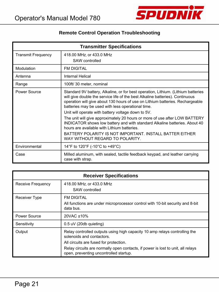
Transmitter Specifications
Transmit Frequency 418.00 MHz, or 433.0 MHzSAW controlled
Modulation FM DIGITAL
Antenna Internal Helical
Range 100ft/ 30 meter, nominal
Power Source Standard 9V battery, Alkaline, or for best operation, Lithium. (Lithium batteries will give double the service life of the best Alkaline batteries). Continuous operation will give about 130 hours of use on Lithium batteries. Rechargeable batteries may be used with less operational time.Unit will operate with battery voltage down to 5V.The unit will give approximately 20 hours or more of use after LOW BATTERY INDICATOR shows low battery and with standard Alkaline batteries. About 40 hours are available with Lithium batteries.BATTERY POLARITY IS NOT IMPORTANT. INSTALL BATTER EITHER WAY WITHOUT REGARD TO POLARITY.
Environmental 14°F to 120°F (-10°C to +49°C)
Case Milled aluminum, with sealed, tactile feedback keypad, and leather carrying case with strap.
Relay controlled outputs using high capacity 10 amp relays controlling the solenoids and contactors.All circuits are fused for protection.Relay circuits are normally open contacts, if power is lost to unit, all relays open, preventing uncontrolled startup.
Output
0.5 uV (20db quieting)Sensitivity
20VAC ±10%Power Source
FM DIGITALAll functions are under microprocessor control with 10-bit security and 8-bit data bus.
Receiver Type
418.00 MHz, or 433.0 MHzSAW controlled
Receive Frequency
Receiver Specifications
Operator's Manual Model 780
Page 21
Remote Control Operation Troubleshooting
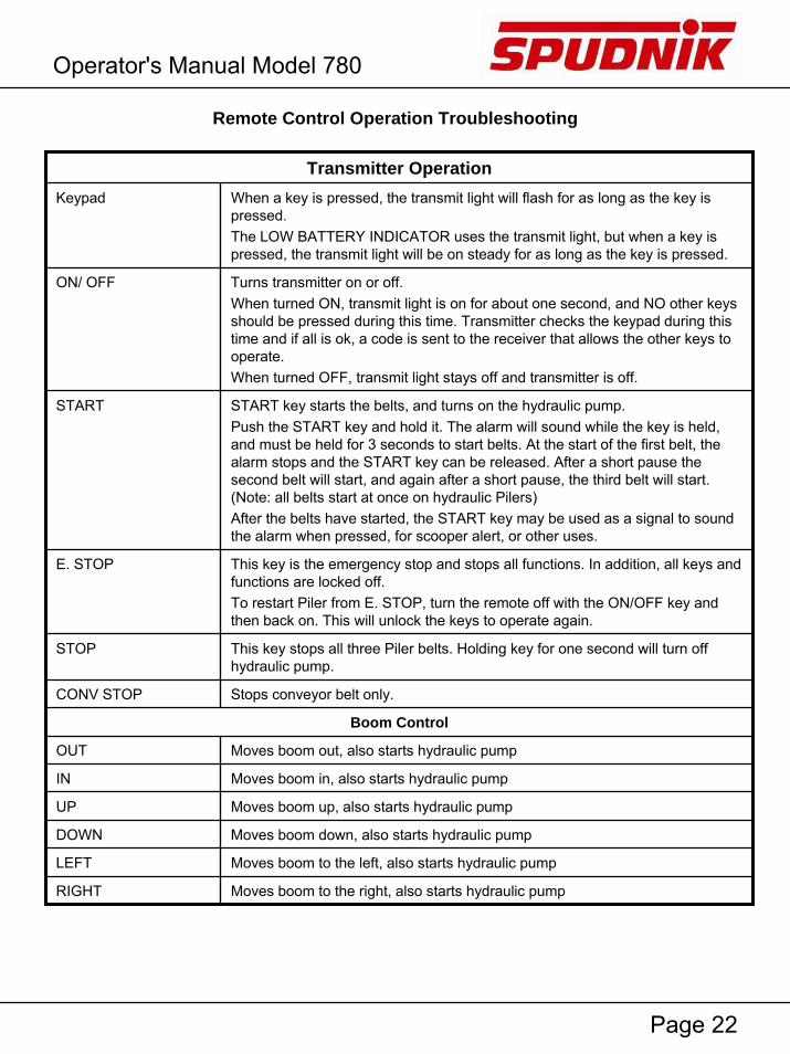
Transmitter Operation
Keypad When a key is pressed, the transmit light will flash for as long as the key is pressed.The LOW BATTERY INDICATOR uses the transmit light, but when a key is pressed, the transmit light will be on steady for as long as the key is pressed.
ON/ OFF Turns transmitter on or off. When turned ON, transmit light is on for about one second, and NO other keys should be pressed during this time. Transmitter checks the keypad during this time and if all is ok, a code is sent to the receiver that allows the other keys to operate.When turned OFF, transmit light stays off and transmitter is off.
START START key starts the belts, and turns on the hydraulic pump.Push the START key and hold it. The alarm will sound while the key is held, and must be held for 3 seconds to start belts. At the start of the first belt, the alarm stops and the START key can be released. After a short pause the second belt will start, and again after a short pause, the third belt will start. (Note: all belts start at once on hydraulic Pilers)After the belts have started, the START key may be used as a signal to sound the alarm when pressed, for scooper alert, or other uses.
E. STOP This key is the emergency stop and stops all functions. In addition, all keys and functions are locked off.To restart Piler from E. STOP, turn the remote off with the ON/OFF key and then back on. This will unlock the keys to operate again.
STOP This key stops all three Piler belts. Holding key for one second will turn off hydraulic pump.
CONV STOP Stops conveyor belt only.
Boom Control
OUT Moves boom out, also starts hydraulic pump
IN Moves boom in, also starts hydraulic pump
UP Moves boom up, also starts hydraulic pump
DOWN Moves boom down, also starts hydraulic pump
LEFT Moves boom to the left, also starts hydraulic pump
RIGHT Moves boom to the right, also starts hydraulic pump
Operator's Manual Model 780
Page 22
Remote Control Operation Troubleshooting
Transmitter Operation
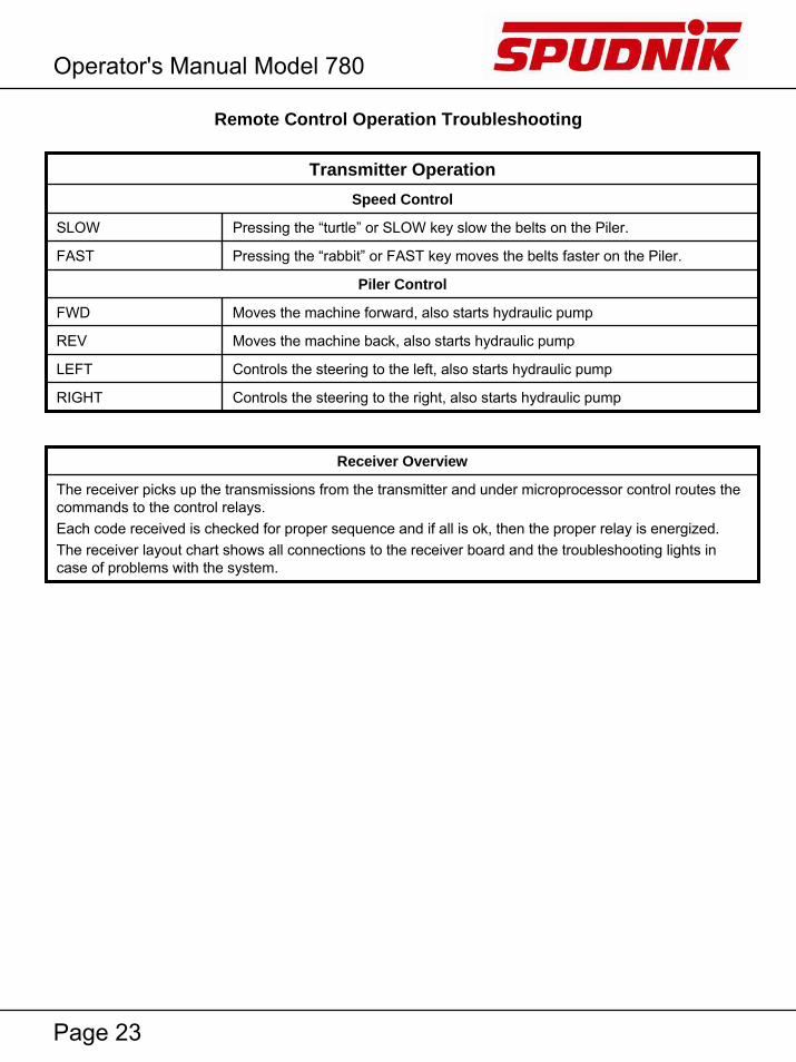
Speed Control
SLOW Pressing the “turtle” or SLOW key slow the belts on the Piler.
FAST Pressing the “rabbit” or FAST key moves the belts faster on the Piler.
FWD Moves the machine forward, also starts hydraulic pump
REV Moves the machine back, also starts hydraulic pump
LEFT Controls the steering to the left, also starts hydraulic pump
RIGHT Controls the steering to the right, also starts hydraulic pump
Piler Control
The receiver picks up the transmissions from the transmitter and under microprocessor control routes the commands to the control relays.Each code received is checked for proper sequence and if all is ok, then the proper relay is energized.The receiver layout chart shows all connections to the receiver board and the troubleshooting lights in case of problems with the system.
Receiver Overview
Operator's Manual Model 780
Page 23
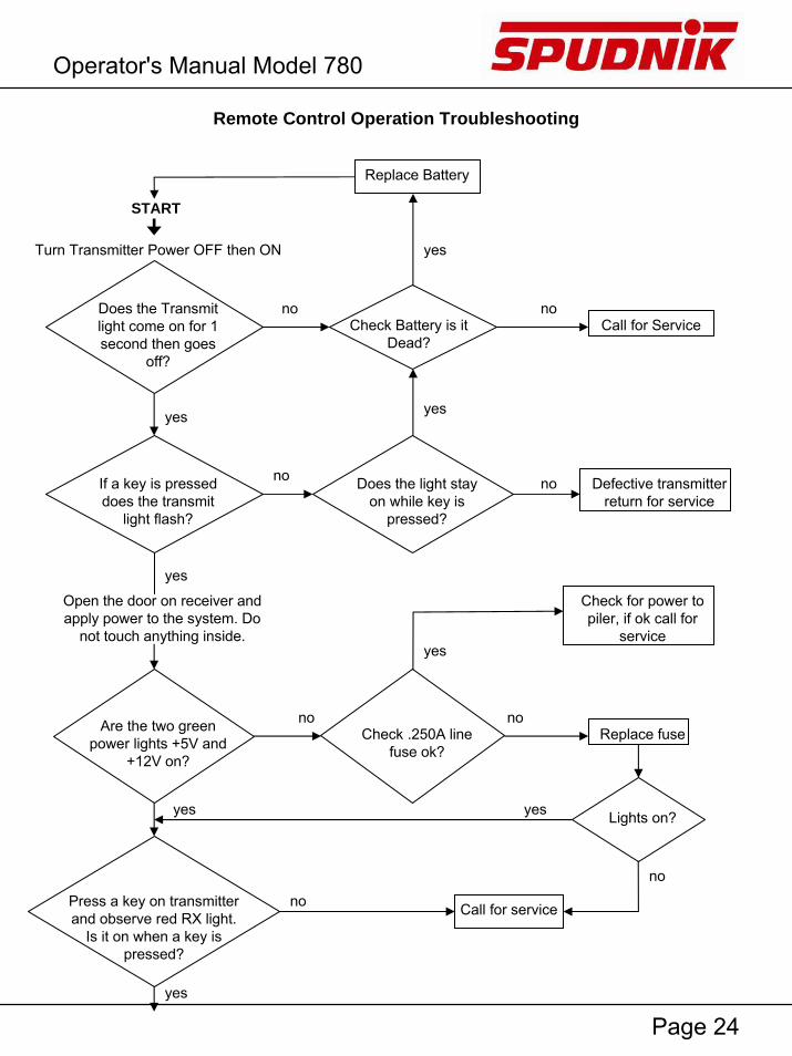
Remote Control Operation Troubleshooting
Does the Transmit light come on for 1 second then goes
off?
Check Battery is it Dead?
Call for Service
Replace Battery
START
Turn Transmitter Power OFF then ON
If a key is pressed does the transmit
light flash?
Does the light stay on while key is
pressed?
Defective transmitter return for service
Open the door on receiver and apply power to the system. Do
not touch anything inside.
Are the two green power lights +5V and
+12V on?
Press a key on transmitter and observe red RX light.
Is it on when a key is pressed?
Check .250A line fuse ok?
Call for service
Lights on?
Replace fuse
Check for power to piler, if ok call for
service
yes
yes
yes
yes
yes
yes
yes
yes
no no
nono
nono
no
no
Operator's Manual Model 780
Page 24
yes
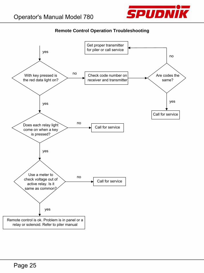
Remote Control Operation Troubleshooting
With key pressed is the red data light on?
Check code number on receiver and transmitter
Are codes the same?
Get proper transmitter for piler or call service
Does each relay light come on when a key
is pressed?
Call for service
Use a meter to check voltage out of
active relay. Is it same as common?
Remote control is ok. Problem is in panel or a relay or solenoid. Refer to piler manual
Call for service
yes
yes
no
no
no
Call for serviceno
yes
yes
Operator's Manual Model 780
Page 25
Remote Control Operation Troubleshooting
Refer to the receiver function chart to aid in locating the specific test lights.
1. First check the battery in the transmitter to verify if it is indeed a good battery. To do this, turn on the transmitter with the ON/OFF key and push a key. (The STOP is good to use as it will not activate the Piler). Check to see that the transmit light is blinking while the key is pressed. If it is on all the time the key is pressed or not on at all, then the battery is low and should be replaced.
Reread transmitter operation section of this manual to be sure that proper sequence is used to turn on, off and use the transmitter.
2. Open the door on the receiver and with power applied to the receiver, check the two green lights labeled +5V and +12V. Both lights should be on. If only one is on, call for service. If both lights are off, first check that there is power to the Piler. If yes, turn off the power to the Piler, and check the fuse labeled MAIN .250A. If it is bad, use the spare one labeled (SPARE .250A MAIN FUSE). Turn on power to unit. This should restore the two green lights to ON. If not, call for service.
3. Locate the red RX light. Push a key on the transmitter and observe the RX light.
When a key is pressed the light should be ON, and when released it should be OFF, if not call for service. If the RX light comes ON< then check the DATA red light and verify that it comes ON when a key is press4ed. It will come ON slightly after the RX light, and if not the transmitter code may be set for a different receiver. Transmitter and receiver must have the same code. Code is set at the factory and should not be changed. Each Piler has it’s own unique code and will not operate another Piler. Check the front of this manual for proper code, and check serial number of transmitter and receiver to see that the first four numbers are the same. If not, call for service.
4. Next, check that each relay light comes on as a key is pressed and that the corresponding relay activates at the same time.
5. Use a meter to verify voltage out of the activated relay terminal. It should be the same voltage as on the COMMON of the corresponding terminal block. If not, check the fuse associated with the affected relay. A spare fuse is available at the location labeled (SPARE RELAY FUSE). After replacing the fuse, verify that voltage is available out of the activated relay terminal.
6. If the fuse does not repair the problem, a contactor or solenoid may be defective or the relay may be at fault. Call for service.
Operator's Manual Model 780
Page 26
Remote Control Operation TroubleshootingTransmitter Quick Operation
1. Install battery in battery compartment. Battery may be installed either way without regard to battery polarity.
2. Turn on remote with ON/OFF green key
3. Unit checks keyboard at this time so push only the ON/OFF key.
4. Push start key and hold it for 3 seconds to start belts. The alarm will sound during this time and stops when the belts start. After this time pressing START key will sound the alarm while key is pressed for alerting personnel in the area.
5. When Start key is pressed, the hydraulic pump will start.
6. Push STOP key to stop belts. May be restarted as in #4 above. Hold STOP key for one second to shutoff hydraulic pump.
7. E. STOP stops all functions and requires turning off the remote with the ON/OFF key and then back on as in step #2 to start again.
8. All other keys work as shown on the operational diagram and are momentary keys.
Operator's Manual Model 780
Page 27
MaintenanceGeneral safety instructions
Regular maintenance is a prerequisite for operational reliability. The following safety advice is to be observed during any maintenance, cleaning or repair work.
To prevent accidents, all relevant rules and regulations concerning safe and competent working must be observed!
•Observe the adjustment, maintenance and inspection activities and intervals specified in this operating manual, including details concerning the replacement of parts, subassemblies and equipment. These activities may only be executed by trained personnel.
•Instruct operating personnel before beginning special operations and maintenance work! Delegate a supervisor!
•Always observe the relevant safety measures and instructions specified in the operating manual when carrying out work related to the operation, adaptation, conversion or adjustment of the machine as well as maintenance, inspection and repair activities.
•Ensure the working area is adequately secured during the maintenance work!
•Use suitable, tested tools when working on the machine. Wear gloves!
•Switch off the machine completely before maintenance and repair work and ensure that it is secured against inadvertent starting. The machine must not be switched on again while the work is being carried out!
-Switch off operating facilities.
-In the case of tractors, self-propelled harvesting machines and engine-driven machines, switch off the engine, remove the ignition key and, if necessary, lock the cabin. Nobody is allowed to be within reach of the controls so that functions cannot be switched on again by accident.
-Switch off the main switch and attach a warning sign, if necessary.
-Disconnect the machine from the power supply. Depressurize the hydraulic system and compressed air lines and disconnect them from the supply.
•Carry out maintenance and repair work only when the machine is positioned on firm and level ground and has been secured against inadvertent movement and toppling.
•When replacing individual parts and larger subassemblies, they should be carefully attached to lifting gear and secured against falling down. To avoid the risk of accidents, sharp edges, corners and dangerous projections must be covered and a warning sign attached. Use only suitable hoisting and lifting gear with adequate load capacity which is in a proper working condition. Never work or stand under suspended loads!
•The securing of loads and the instruction of crane operators should only be entrusted to experienced persons. A signaler giving instructions must be within sight of the crane operator and must be provided with a radio link.
•Only carry out overhead assembly work using suitable ladders and platforms. Never climb on the machine itself! Wear a safety harness when carrying out maintenance work at greater heights.
•Keep all handles, steps, handrails, platforms, landings and ladders free from dirt, snow and ice.
Operator's Manual Model 780
Page 28

Maintenance
•Clean the machine, especially connections and threaded unions of any traces of oil, fuel or preservatives before carrying out maintenance/repairs. Never use aggressive detergents. Use lint-free cleaning cloths.
•Before cleaning the machine with water or steam jets (high-pressure cleaners) or other cleaning agents, cover or tape all openings which – for safety and operational reasons - must be protected against ingress of water, steam or leaning agents. Special care must be taken with electric motors and switching cabinets, as well as all additional electrical or electronic components. After cleaning, remove all covers and tape completely.
•After cleaning, examine all fuel, lubricant and hydraulic oil lines for leaks, loose connections, scuffing marks and damage,. Any defects found must be rectified without delay.
•Immediately retighten any screwed connections that have been unscrewed during maintenance and repairs.
•Any safety devices removed for setting-up, maintenance or repair purposes must be refitted and checked immediately upon completion of the maintenance and repair work.
•Ensure that all fuels, consumables and replaced parts are disposed of safely and with minimum environmental impact.
Operator's Manual Model 780
Page 29
Maintenance
Special safety instructions
Safety devices
Never stand beneath suspended loads!
Never stand or work beneath suspended loads!Engage safety catches!
Never stand or work beneath suspended loads.
Adjustment and maintenance work on these parts of the machine may only be carried out with the safety devices engaged.
Operator's Manual Model 780
Page 30
Maintenance
Spare parts procurement
Please quote the details on the type plate(s) as well as the machine’s serial no. on every order for spare parts or accessories, or inquires of a technical nature.
The use of spare parts supplied by third parties Is prohibited. Original spare parts and accessories approved by the manufacturer are a contribution to safety and guarantee proper functioning. No liability can be taken for consequences resulting from the use of other parts.
When replacing electrical or hydraulic parts, ensure that only original SPUDNIK spare parts are used. The use of non-SPUDNIK parts can cause malfunctioning of the machine.
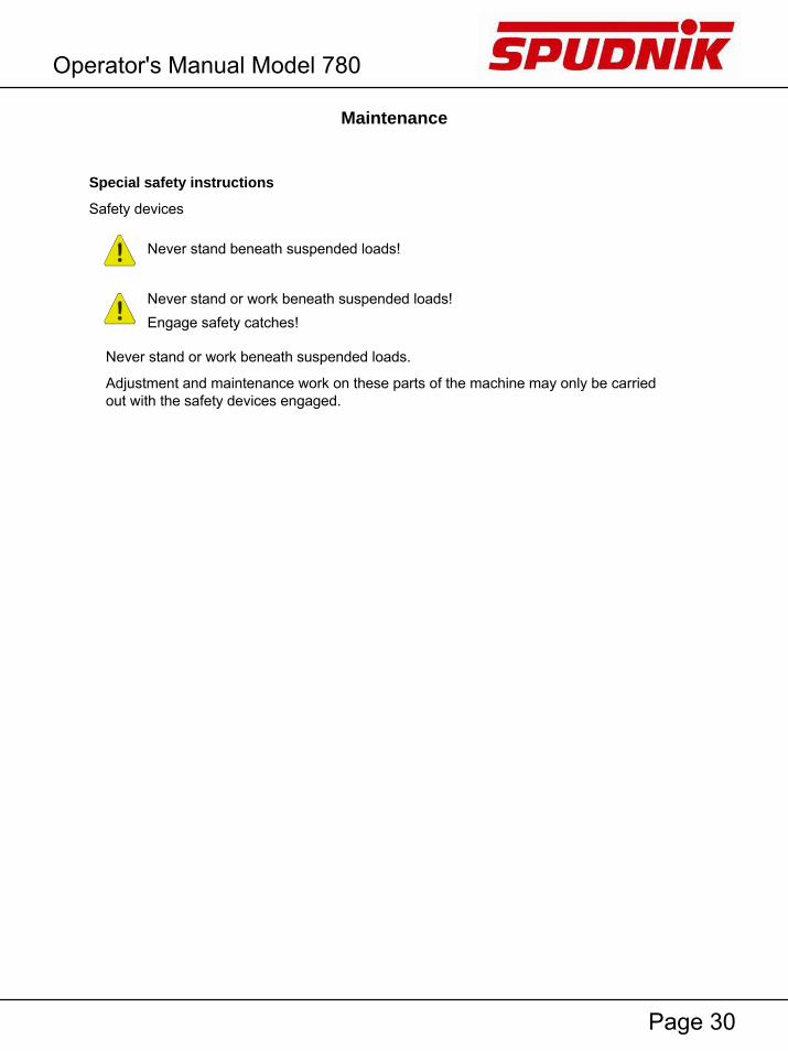
Type plate on machine
Machine serial numberThe machine serial no. is punched intoa plate on the frame.
The entire designation has the status of a legal document and may not be removed, changed or rendered illegible!
Disposing of replaced parts
The following points should be observed before replacing or disposing of parts.
-Replaced parts which still function should be cleaned and stored in an orderly manner.
-Machine parts which cannot be repaired should only be disposed of at appropriate collecting points or be collected by a scrap metal dealer.
So called “valuable” materials should be deposed of in a proper way, i.e. plastics, rubber, scrap metal, etc. should be recycled.
Collect and dispose of old oil in accordance with the regulations.
Operator's Manual Model 780
Page 31
Repairs to the electrical system may only be carried out by authorized dealers.
Exercise extreme care when working on engine or hydraulics – risk of serious burns!
In order to keep wear down to a minimum, clean the machine thoroughly inside and outside. Non-observance of the instructions can lead to malfunctions or premature wear. In this case the user carries sole responsibility for any damage which occurs.
To ensure the operational reliability of the machine, prevent accidents and avoid, damage, remove dirt, deposits and inflammable materials from the machine on a daily basis!
Only carry out cleaning work when the engine is switched off!
Remove the ignition key!
Secure the machine against rolling away!
Protect the electrical system from moisture and dirt. This particularly applies when cleaning high pressure cleaning equipment.
Maintenance
Cleaning after every operation
In order to keep wear down to a minimum, follow the instructions given below:
-Remove dirt, deposits and flammable material from the machine on a daily basis.
-Inspect the machine for damage once a week and replace defective parts immediately
-Take note of and comply with the information regarding cleaning with high-pressure cleaning equipment.
The following figure show the parts of the machine, which must be cleaned after each use:
Operator's Manual Model 780
Page 32
Maintenance
Parts to be cleaned
Cleaning with high-pressure cleaning equipment
Clean the machine thoroughly, inside and outside. Dirt attracts moisture and leads to corrosion. The following advice should be adhered to when using high-pressure cleaning equipment to wash down the machine:
Cleaning instructions:
During the first six weeks do not wash down the machine with high-pressure cleaning equipment.
Thereafter:
-Do not direct the jet of water at bearings.
-Do not direct the cleaning jet towards electrical/electronic components.
-Only use a wide-jet nozzle; machine nozzle clearance to be min. 2ft (600 mm).
-Always keep the wide-jet nozzle moving from side to side.
-Nozzle spraying angle min. 25degrees.
-Spraying pressure max. 1450 psi.
-Water temperature max. 68 degrees Fahrenheit.
-Do not use any cleaning additives.
Operator's Manual Model 780
Page 33
Maintenance
Storage
Only carry out adjustments and maintenance work when the engine is switched off!Remove ignition key!Secure the machine against rolling away!
Secure machine against rolling away!Engage parking brake and use wheel chocks!
Careful storage of the machine or the spare parts avoids repair costs and downtimes. At the same time, reliability and service life are improved
Make a note of all maintenance work to be carried out before the next season and arrange for this to be carried out in good time.
Your SPUDNIK dealer is in a better position to perform maintenance work and any repairs that may be necessary outside the season.
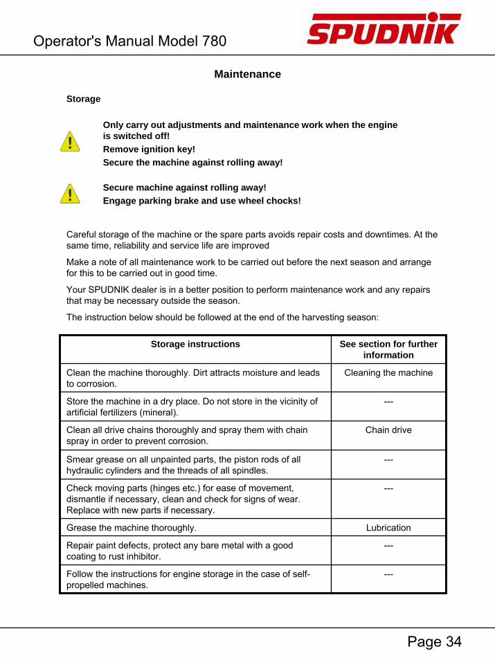
The instruction below should be followed at the end of the harvesting season:
Storage instructions See section for further information
Clean the machine thoroughly. Dirt attracts moisture and leads to corrosion.
Cleaning the machine
Store the machine in a dry place. Do not store in the vicinity of artificial fertilizers (mineral).
---
Clean all drive chains thoroughly and spray them with chain spray in order to prevent corrosion.
Chain drive
Smear grease on all unpainted parts, the piston rods of all hydraulic cylinders and the threads of all spindles.
---
Check moving parts (hinges etc.) for ease of movement, dismantle if necessary, clean and check for signs of wear. Replace with new parts if necessary.
---
Grease the machine thoroughly. Lubrication
Repair paint defects, protect any bare metal with a good coating to rust inhibitor.
---
Follow the instructions for engine storage in the case of self-propelled machines.
---
Operator's Manual Model 780
Page 34
Maintenance
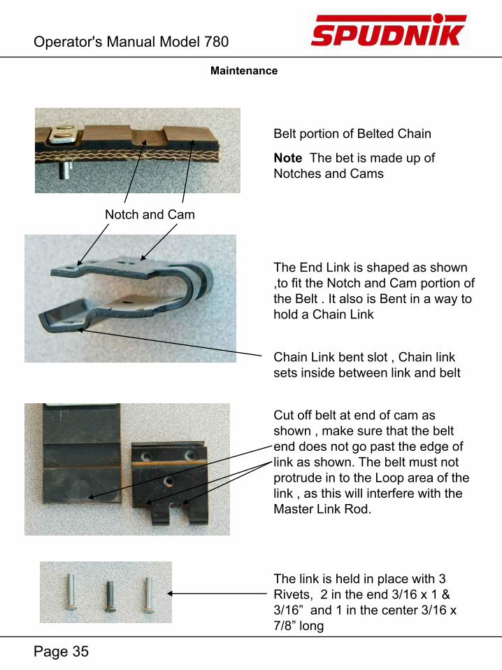
Belt portion of Belted Chain
Note The bet is made up of Notches and Cams
The End Link is shaped as shown ,to fit the Notch and Cam portion of the Belt . It also is Bent in a way to hold a Chain Link
Notch and Cam
Chain Link bent slot , Chain link sets inside between link and belt
Cut off belt at end of cam as shown , make sure that the belt end does not go past the edge of link as shown. The belt must not protrude in to the Loop area of the link , as this will interfere with the Master Link Rod.
The link is held in place with 3 Rivets, 2 in the end 3/16 x 1 & 3/16” and 1 in the center 3/16 x 7/8” long
Operator's Manual Model 780
Page 35
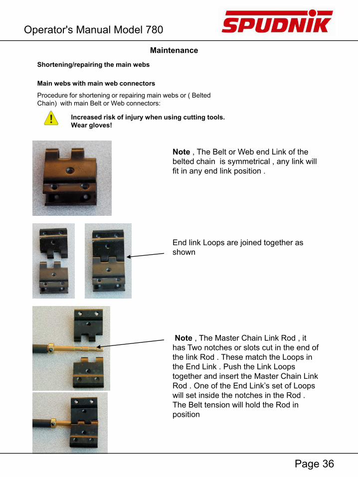
MaintenanceShortening/repairing the main webs
Main webs with main web connectors
Procedure for shortening or repairing main webs or ( Belted Chain) with main Belt or Web connectors:
Increased risk of injury when using cutting tools. Wear gloves!
Note , The Belt or Web end Link of the belted chain is symmetrical , any link will fit in any end link position .
End link Loops are joined together as shown
Note , The Master Chain Link Rod , it has Two notches or slots cut in the end of the link Rod . These match the Loops in the End Link . Push the Link Loops together and insert the Master Chain Link Rod . One of the End Link’s set of Loops will set inside the notches in the Rod . The Belt tension will hold the Rod in position
Operator's Manual Model 780
Page 36
Maintenance
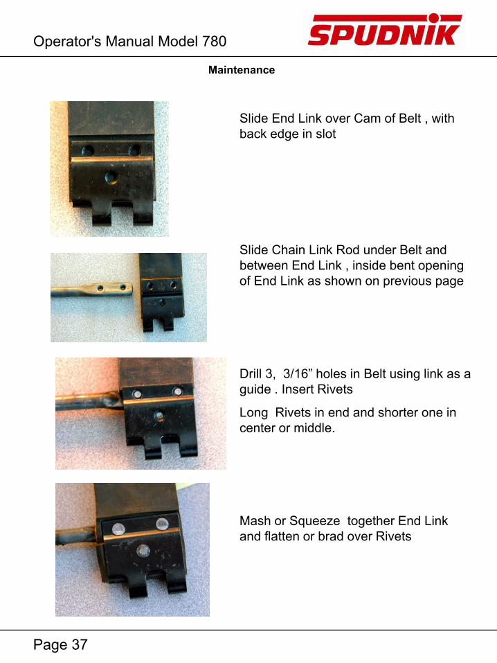
Slide End Link over Cam of Belt , with back edge in slot
Slide Chain Link Rod under Belt and between End Link , inside bent opening of End Link as shown on previous page
Drill 3, 3/16” holes in Belt using link as a guide . Insert Rivets
Long Rivets in end and shorter one in center or middle.
Mash or Squeeze together End Link and flatten or brad over Rivets
Operator's Manual Model 780
Page 37
Maintenance
Screwed connections
Screwed connections in general
Only carry out adjustments and maintenance work when the engine is switched off!
Remove ignition key!
Secure the machine against rolling away!
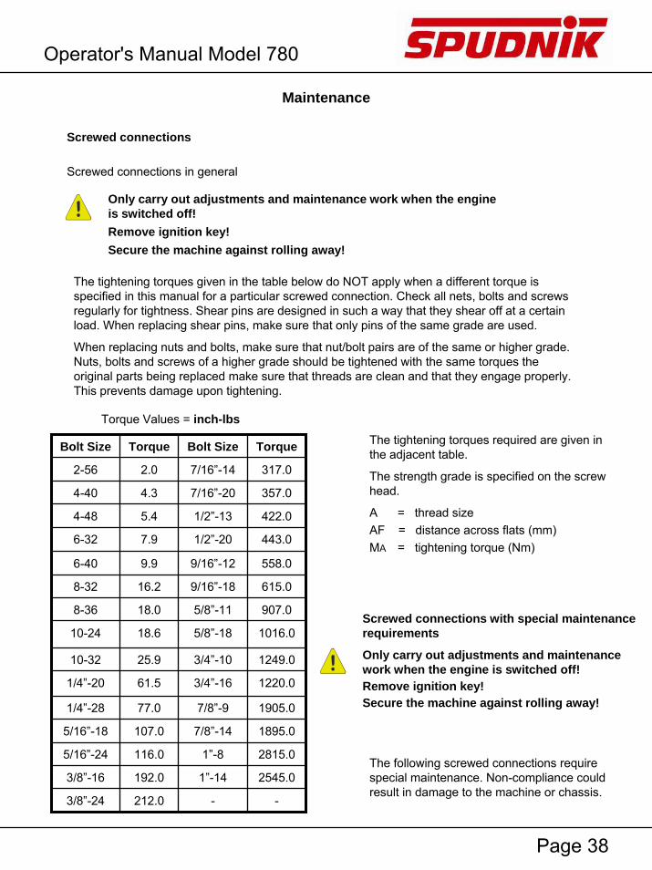
The tightening torques given in the table below do NOT apply when a different torque is specified in this manual for a particular screwed connection. Check all nets, bolts and screws regularly for tightness. Shear pins are designed in such a way that they shear off at a certain load. When replacing shear pins, make sure that only pins of the same grade are used.
When replacing nuts and bolts, make sure that nut/bolt pairs are of the same or higher grade. Nuts, bolts and screws of a higher grade should be tightened with the same torques the original parts being replaced make sure that threads are clean and that they engage properly. This prevents damage upon tightening.
The tightening torques required are given in the adjacent table.
The strength grade is specified on the screw head.
A = thread sizeAF = distance across flats (mm)MA = tightening torque (Nm)
Screwed connections with special maintenance requirements
Only carry out adjustments and maintenance work when the engine is switched off!Remove ignition key!Secure the machine against rolling away!
The following screwed connections require special maintenance. Non-compliance could result in damage to the machine or chassis.
Bolt Size Torque Bolt Size Torque
7/16”-14 317.0
4-40 4.3 7/16”-20 357.0
4-48 5.4 1/2”-13 422.0
6-32 7.9 1/2”-20 443.0
6-40 9.9 9/16”-12 558.0
8-32 16.2 9/16”-18 615.0
8-36 18.0 5/8”-11 907.0
10-24 18.6 5/8”-18 1016.0
10-32 25.9 3/4”-10 1249.0
1/4”-20 61.5 3/4”-16 1220.0
1/4”-28 77.0 7/8”-9 1905.0
5/16”-18 107.0 7/8”-14 1895.0
5/16”-24 116.0 1”-8 2815.0
3/8”-16 192.0 1”-14 2545.0
3/8”-24 212.0 - -
2-56 2.0
Torque Values = inch-lbs
Operator's Manual Model 780
Page 38
Maintenance
Main web connecting pieces
All main webs and discharge conveyor belts are fitted with a connecting piece so that each web can be easily changed.
The screws of the connecting pieces are to be checked for tightness at the following intervals:
-After the first digging operation,-After 50 operating hours,-Thereafter, every 200 operating hours.
Drawbar eye for hitch and Piton-Fix couplings
The screwed connection shown must be checked for tightness at the following intervals:
-Prior to the first use under load,-After the first use under load,-After 50 operating hours,-After 100 operating hours, -Thereafter, every 200 operating hours.Type of bolt: 1” UNCNo. of bolt: 2Tightening torque: 250 ft lb
Operator's Manual Model 780
Page 39
Maintenance
Chassis
Any adjustments or repairs to the chassis which are not shown here may only be carried out by an authorized dealer.
Non-compliance with this rule invalidated the warranty.
The adjustments shown here may only be carried out when the engine is switched off!
Remove ignition key!
Secure machine against rolling away!
Never overload axles, brakes or chassis.
Note: Use a torque wrench to tighten the wheel nuts!
Tires
Repair work to the wheels may only be carried out by an authorized dealer.
Only work on the wheels when the engine is switched off!
Remove ignition key!
Secure the machine against rolling away!
Maintain the prescribed tire pressures and measure once a week (see technical specifications)
There is a risk of bursting if the tire pressures are too high!
Stand clear of the tires when pumping them up.
Check tire pressures regularly.
Tires with divided rim: Release tire pressure before attempting repairs!
When working on the wheels, secure the machine against rolling away (wheel chocks)!
Never work on machine which is supported only by a jack.
Make sure that the jack has adequate load-carrying capacity.
Operator's Manual Model 780
Page 40
Maintenance
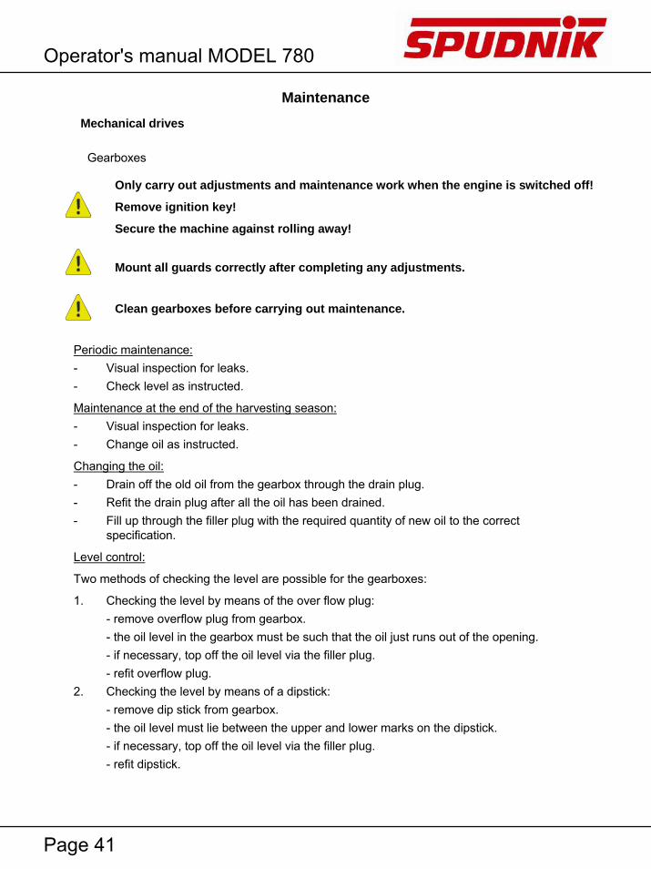
Mechanical drives
Gearboxes
Only carry out adjustments and maintenance work when the engine is switched off!
Remove ignition key!
Secure the machine against rolling away!
Mount all guards correctly after completing any adjustments.
Clean gearboxes before carrying out maintenance.
Periodic maintenance:- Visual inspection for leaks.- Check level as instructed.
Maintenance at the end of the harvesting season:- Visual inspection for leaks.- Change oil as instructed.
Changing the oil:- Drain off the old oil from the gearbox through the drain plug.- Refit the drain plug after all the oil has been drained.- Fill up through the filler plug with the required quantity of new oil to the correct
specification.
Level control:
Two methods of checking the level are possible for the gearboxes:
1. Checking the level by means of the over flow plug:- remove overflow plug from gearbox.- the oil level in the gearbox must be such that the oil just runs out of the opening.- if necessary, top off the oil level via the filler plug.- refit overflow plug.
2. Checking the level by means of a dipstick:- remove dip stick from gearbox.- the oil level must lie between the upper and lower marks on the dipstick.- if necessary, top off the oil level via the filler plug.- refit dipstick.
Operator's manual MODEL 780
Page 41
Maintenance
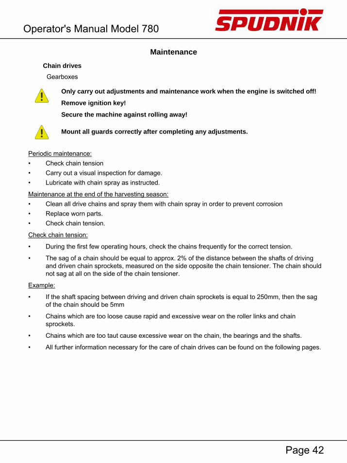
Chain drives
Gearboxes
Only carry out adjustments and maintenance work when the engine is switched off!
Remove ignition key!
Secure the machine against rolling away!
Mount all guards correctly after completing any adjustments.
Periodic maintenance:• Check chain tension• Carry out a visual inspection for damage.• Lubricate with chain spray as instructed.
Maintenance at the end of the harvesting season:• Clean all drive chains and spray them with chain spray in order to prevent corrosion• Replace worn parts.• Check chain tension.
Check chain tension:
• During the first few operating hours, check the chains frequently for the correct tension.
• The sag of a chain should be equal to approx. 2% of the distance between the shafts of driving and driven chain sprockets, measured on the side opposite the chain tensioner. The chain should not sag at all on the side of the chain tensioner.
Example:
• If the shaft spacing between driving and driven chain sprockets is equal to 250mm, then the sag of the chain should be 5mm
• Chains which are too loose cause rapid and excessive wear on the roller links and chain sprockets.
• Chains which are too taut cause excessive wear on the chain, the bearings and the shafts.
• All further information necessary for the care of chain drives can be found on the following pages.
Operator's Manual Model 780
Page 42

Maintenance
Belt drives
Only carry out adjustments and maintenance work when the engine is switched off!
Remove ignition key!
Secure the machine against rolling away!
Mount all guards correctly after completing any adjustments.
Periodic maintenance:• Check belt tension.• Carry out a visual inspection for damage.
Maintenance at the end of the harvesting season:• Detension all drive belts.• Replace worn parts.
Check belt tension:
• Loosen the pulleys when fitting a new belt. Never force a belt over a pulley as this will damage the
• integral fibers and hence weaken the belt. • New belts stretch initially. Therefore, retension frequently during the first few days. More belts are
ruined through inadequate tension than through excessive tension!
Operator's manual MODEL 780
Page 43

Maintenance
Lubrication
Only carry out adjustments and maintenance work when the engine is switched off!
Remove ignition key!
Secure the machine against rolling away!
Mount all guards correctly after completing any adjustments.
Only use a good quality brand-name grease, e.g. Shell Retinaz A EP2 multipurpose grease.
Remove dirt from lubrication nipples prior to applying grease. Wipe away any excess grease escaping from bearings.
Operator's Manual Model 780
Page 44

Maintenance
Hydraulic system
Only carry out adjustments and maintenance work when the engine is switched off!Remove ignition key!Secure the machine against rolling away!
The hydraulic system is under high pressure!Fluids escaping under high pressure can penetrate the skin and cause serious injuries! If such injuries occur, call a doctor immediately as otherwise there is a risk of serious infection!
Repair work to the hydraulic system may only be carried out by an authorized dealer.
Hydraulic oil and used oil filters are to be stored in suitable containers and disposed of in accordance with the regulations.
Caution! Hot oil can cause serious burns!
Only work on the hydraulic system when the engine is switched off!Remove ignition key!Secure the machine against rolling away!
Hydraulic cylinders
Prior to storing the machine (e.g. for winter period), all hydraulic cylinders must be cleaned and completely retracted to protect them against contamination and corrosion. If a complete retraction is not possible, lubricate the cylinders and cover them by means of a blanket. Contaminated and corroded cylinder rods my damage the seals of the hydraulic cylinders when being retracted/extended the first time after the winter storage!
Periodic maintenance:
-Visual inspection for leads.-Check contamination indicator on filter (only with optional separate hydraulics)
Maintenance at the end of the harvesting season:
-Change filter as instructed
Changing the filter:
-Cleanliness is important when changing a filter.-Insert the new filter immediately after removing the old one.-Release filter, unscrew and replace with an original SPUDNIK filter.
Insert the new filter as follows:
-Moisten the sealing face with oil.-After the filter seal has made contact with the sealing face of the filter housing, tighten the filter approximately one more turn.-Check the filter for leads after a test run; retighten if necessary.-Check the hydraulic fluid level and top up if necessary.
Operator's manual MODEL 780
Page 45
Maintenance
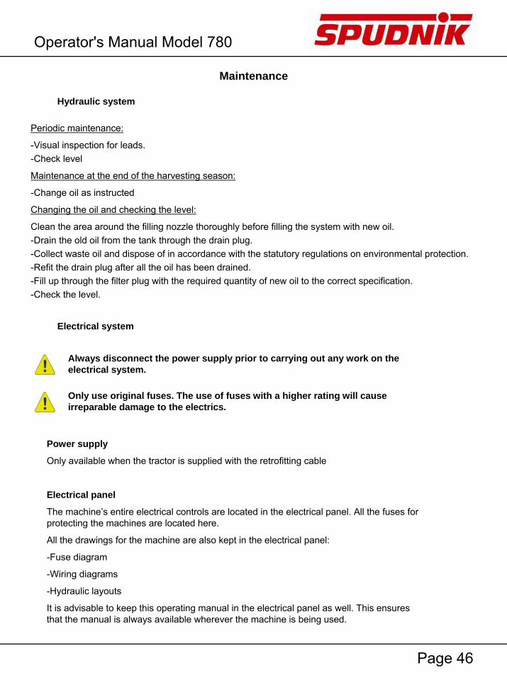
Hydraulic system
Periodic maintenance:
-Visual inspection for leads.-Check level
Maintenance at the end of the harvesting season:
-Change oil as instructed
Changing the oil and checking the level:
Clean the area around the filling nozzle thoroughly before filling the system with new oil.-Drain the old oil from the tank through the drain plug.-Collect waste oil and dispose of in accordance with the statutory regulations on environmental protection.-Refit the drain plug after all the oil has been drained.-Fill up through the filter plug with the required quantity of new oil to the correct specification.-Check the level.
Electrical system
Always disconnect the power supply prior to carrying out any work on the electrical system.
Only use original fuses. The use of fuses with a higher rating will cause irreparable damage to the electrics.
Power supply
Only available when the tractor is supplied with the retrofitting cable
Electrical panel
The machine’s entire electrical controls are located in the electrical panel. All the fuses for protecting the machines are located here.
All the drawings for the machine are also kept in the electrical panel:
-Fuse diagram
-Wiring diagrams
-Hydraulic layouts
It is advisable to keep this operating manual in the electrical panel as well. This ensures that the manual is always available wherever the machine is being used.
Operator's Manual Model 780
Page 46
Maintenance
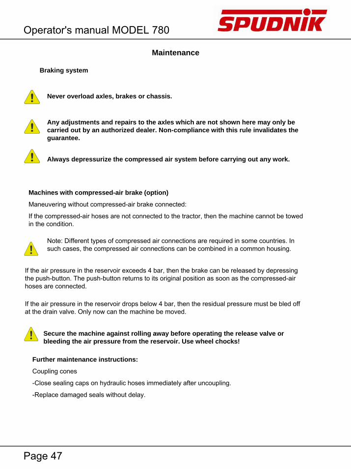
Braking system
Never overload axles, brakes or chassis.
Any adjustments and repairs to the axles which are not shown here may only be carried out by an authorized dealer. Non-compliance with this rule invalidates the guarantee.
Always depressurize the compressed air system before carrying out any work.
Machines with compressed-air brake (option)
Maneuvering without compressed-air brake connected:
If the compressed-air hoses are not connected to the tractor, then the machine cannot be towed in the condition.
Note: Different types of compressed air connections are required in some countries. In such cases, the compressed air connections can be combined in a common housing.
If the air pressure in the reservoir exceeds 4 bar, then the brake can be released by depressing the push-button. The push-button returns to its original position as soon as the compressed-air hoses are connected.
If the air pressure in the reservoir drops below 4 bar, then the residual pressure must be bled off at the drain valve. Only now can the machine be moved.
Secure the machine against rolling away before operating the release valve or bleeding the air pressure from the reservoir. Use wheel chocks!
Further maintenance instructions:
Coupling cones
-Close sealing caps on hydraulic hoses immediately after uncoupling.
-Replace damaged seals without delay.
Operator's manual MODEL 780
Page 47

Notes !!
Operator's Manual Model 780
Page 48
Machine Parts Breakdown
Description_______________________________________________________
Belt And Belted Chain Information…………………..………...……………
Front Axle ………….....................……………………..……….……………
Rear Axle ………….........………………………………..…….……………
Crab Steering Rear Axle ..………………….............……..…..……………
Outrigger Assembly ………………............…………………………………
Standard Hitch ……..……...………………..…………………..……………
Hydraulic Hitch …....………………………..………………….……………
Post Assembly ……………………………….………………....……………
Frame Assembly ……………...………………..……………….……………
Dirt Cross Conveyor ..……........……………………………………………
Upright Light RH Assembly …..………………………………..……………
37" Elevator ……………………..……………………...............……………
43" Elevator …………................……………………………………………
Elevator and Boom Hyd Lifts ………………………………….……………
Two Belt Boom Assembly ……….……………………………..……………
Continuous Belt Boom Assembly ……………………...……...……………
Boom Assist …..…………………….…………………………..……………
Towing Braces ………………………………………………………………
Schematics ……..………………………………………………....………….
Page #
50
52
53
54
56
57
58
60
62-64
65
66
68
70
72
74-82
84-92
94
96
97
Operator's Manual Model 780
Page 49
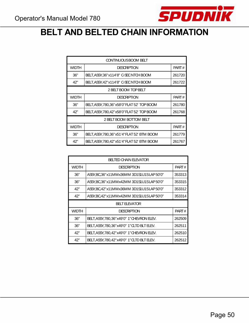
BELT AND BELTED CHAIN INFORMATION
BELTED CHAIN ELEVATOR
WIDTH DESCRIPTION PART #
36" ASSY,BC,36"x11MMx36MM 3D1S1U1S LAP 50'0" 353313
36" ASSY,BC,36"x11MMx42MM 3D1S1U1S LAP 50'0" 353315
42" ASSY,BC,42"x11MMx36MM 3D1S1U1S LAP 50'0" 353312
42" ASSY,BC,42"x11MMx42MM 3D1S1U1S LAP 50'0" 353314
BELT ELEVATOR
WIDTH DESCRIPTION PART #
36" BELT,ASSY,780,36"x49'0" 1"CHEVRON ELEV. 262509
36" BELT,ASSY,780,36"x49'0" 1"CLTD BLT ELEV. 262511
42" BELT,ASSY,780,42"x49'0" 1"CHEVRON ELEV. 262510
42" BELT,ASSY,780,42"x49'0" 1"CLTD BLT ELEV. 262512
CONTINUOUS BOOM BELT
WIDTH DESCRIPTION PART #
36" BELT,ASSY,36"x114'8" C-SEC NTCH BOOM 261720
42" BELT,ASSY,42"x114'8" C-SEC NTCH BOOM 261722
2 BELT BOOM TOP BELT
WIDTH DESCRIPTION PART #
36" BELT,ASSY,780,36"x58'0"FLAT 52' TOP BOOM 261780
42" BELT,ASSY,780,42"x58'0"FLAT 52' TOP BOOM 261768
2 BELT BOOM BOTTOM BELT
WIDTH DESCRIPTION PART #
36" BELT,ASSY,780,36"x51'4"FLAT 52' BTM BOOM 261779
42" BELT,ASSY,780,42"x51'4"FLAT 52' BTM BOOM 261767
Operator's Manual Model 780
Page 50
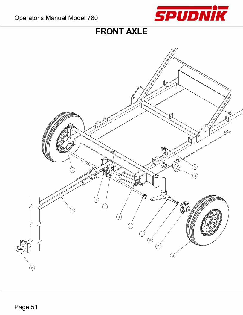
FRONT AXLE
2
3
12
7
8
10
11
4
6
113
5
9
Operator's Manual Model 780
Page 51
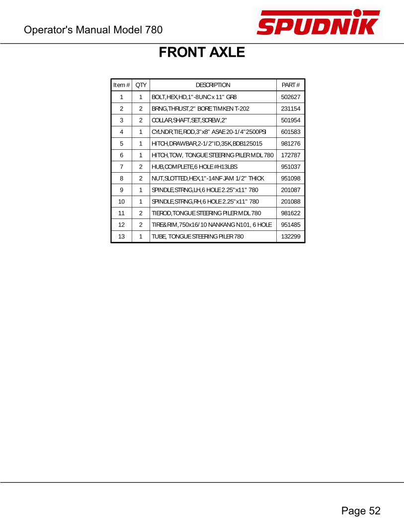
FRONT AXLE
Item # QTY DESCRIPTION PART #
1 1 BOLT,HEX,HD,1"-8UNC x 11" GR8 502627
2 2 BRNG,THRUST,2" BORE TIMKEN T-202 231154
3 2 COLLAR,SHAFT,SET,SCREW,2" 501954
4 1 CYLNDR,TIE,ROD,3"x8" ASAE 20-1/4"2500PSI 601583
5 1 HITCH,DRAWBAR,2-1/2"ID,35K,BDB125015 981276
6 1 HITCH,TOW, TONGUE STEERING PILER MDL 780 172787
7 2 HUB,COMPLETE,6 HOLE #H13LBS 951037
8 2 NUT,SLOTTED,HEX,1"-14NF JAM 1/2" THICK 951098
9 1 SPINDLE,STRNG,LH,6 HOLE 2.25"x11" 780 201087
10 1 SPINDLE,STRNG,RH,6 HOLE 2.25"x11" 780 201088
11 2 TIEROD,TONGUE STEERING PILER MDL 780 981622
12 2 TIRE&RIM,750x16/10 NANKANG N101, 6 HOLE 951485
13 1 TUBE, TONGUE STEERING PILER 780 132299
Operator's Manual Model 780
Page 52
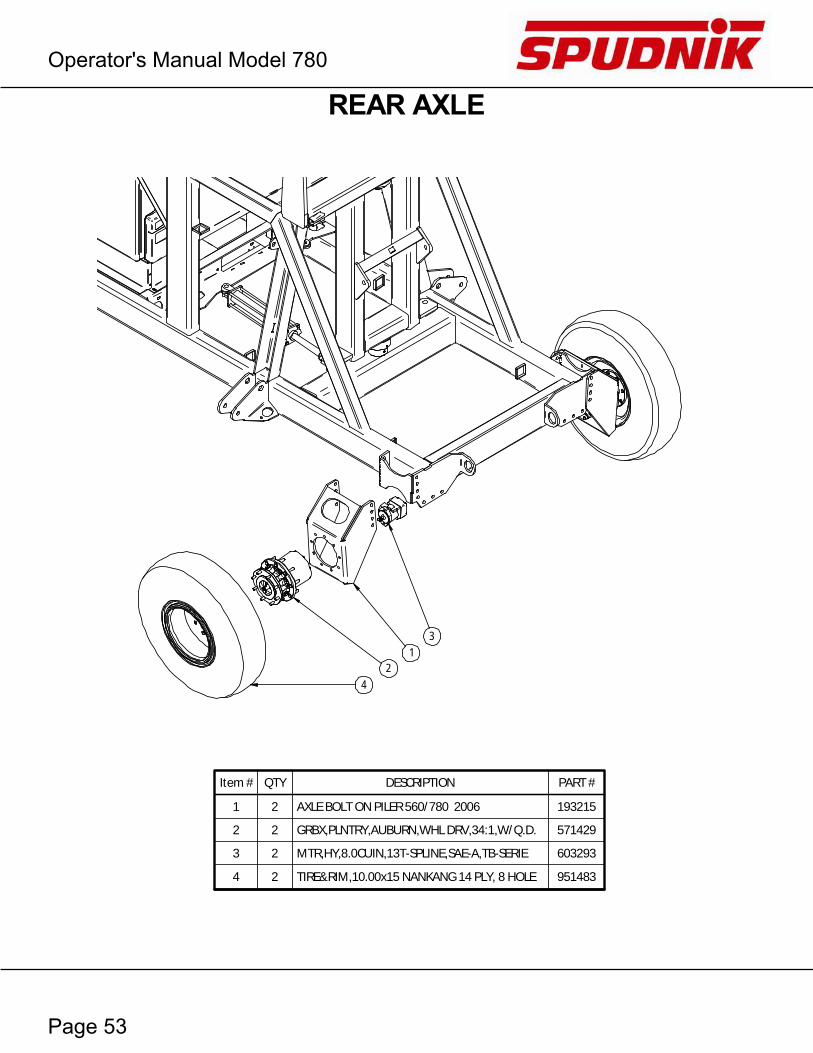
REAR AXLE
4
2
1
3
Item # QTY DESCRIPTION PART #
1 2 AXLE BOLT ON PILER 560/780 2006 193215
2 2 GRBX,PLNTRY,AUBURN,WHL DRV,34:1,W/Q.D. 571429
3 2 MTR,HY,8.0CUIN,13T-SPLINE,SAE-A,TB-SERIE 603293
4 2 TIRE&RIM,10.00x15 NANKANG 14 PLY, 8 HOLE 951483
Operator's Manual Model 780
Page 53
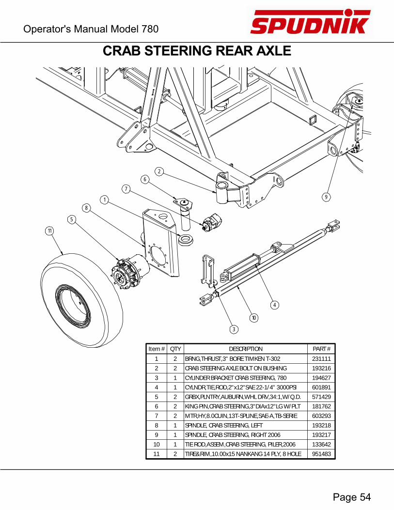
CRAB STEERING REAR AXLE
11
5
8
1
6
7
2
3
10
4
9
Item # QTY DESCRIPTION PART #
1 2 BRNG,THRUST,3" BORE TIMKEN T-302 2311112 2 CRAB STEERING AXLE BOLT ON BUSHING 1932163 1 CYLINDER BRACKET CRAB STEERING, 780 1946274 1 CYLNDR,TIE,ROD,2"x12"SAE 22-1/4" 3000PSI 6018915 2 GRBX,PLNTRY,AUBURN,WHL DRV,34:1,W/Q.D. 5714296 2 KING PIN,CRAB STEERING,3"DIAx12"LG W/PLT 1817627 2 MTR,HY,8.0CUIN,13T-SPLINE,SAE-A,TB-SERIE 6032938 1 SPINDLE, CRAB STEERING, LEFT 1932189 1 SPINDLE, CRAB STEERING, RIGHT 2006 193217
10 1 TIE ROD,ASSEM,CRAB STEERING, PILER,2006 13364211 2 TIRE&RIM,10.00x15 NANKANG 14 PLY, 8 HOLE 951483
Operator's Manual Model 780
Page 54
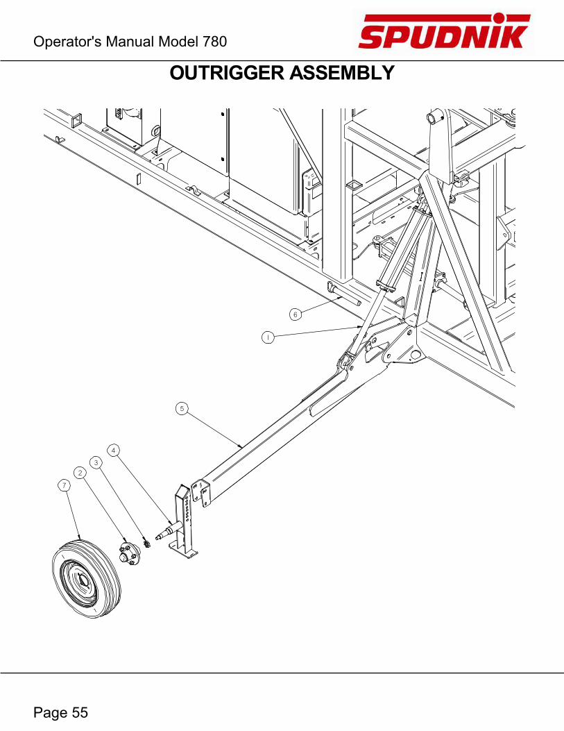
OUTRIGGER ASSEMBLY
7
2
3
4
5
1
6
Operator's Manual Model 780
Page 55
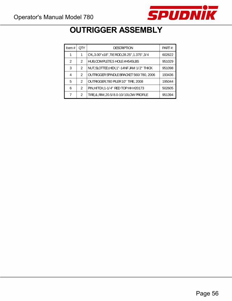
OUTRIGGER ASSEMBLY
Item # QTY DESCRIPTION PART #:
1 1 CYL,3.00"x18",TIE ROD,28.25",1.375",3/4 602622
2 2 HUB,COMPLETE,5 HOLE #H545LBS 951029
3 2 NUT,SLOTTED,HEX,1"-14NF JAM 1/2" THICK 951098
4 2 OUTRIGGER SPINDLE BRACKET 560/780, 2006 193436
5 2 OUTRIGGER,780 PILER 10" TIRE, 2008 195044
6 2 PIN,HITCH,1-1/4" RED TOP HH #20173 502605
7 2 TIRE,&,RIM,20.5/8.0-10/10LOW PROFILE 951394
Operator's Manual Model 780
Page 56
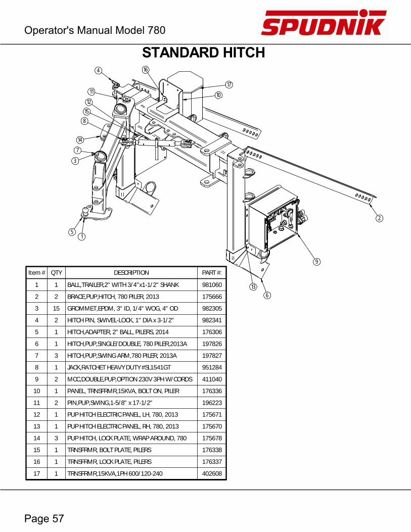
STANDARD HITCH
2
13
12
14
5
16
15
11
6
7
9
1
3
4
8
Item # QTY DESCRIPTION PART #:
1 1 BALL,TRAILER,2" WITH 3/4"x1-1/2" SHANK 981060
2 2 BRACE,PUP,HITCH, 780 PILER, 2013 175666
3 15 GROMMET,EPDM, 3" ID, 1/4" WOG, 4" OD 982305
4 2 HITCH PIN, SWIVEL-LOCK, 1" DIA x 3-1/2" 982341
5 1 HITCH,ADAPTER, 2" BALL, PILERS, 2014 176306
6 1 HITCH,PUP,SINGLE/DOUBLE, 780 PILER,2013A 197826
7 3 HITCH,PUP,SWING ARM,780 PILER, 2013A 197827
8 1 JACK,RATCHET HEAVY DUTY #SL1541GT 951284
9 2 MCC,DOUBLE,PUP,OPTION 230V 3PH W/CORDS 411040
10 1 PANEL, TRNSFRMR,15KVA, BOLT ON, PILER 176336
11 2 PIN,PUP,SWING,1-5/8" x 17-1/2" 196223
12 1 PUP HITCH ELECTRIC PANEL, LH, 780, 2013 175671
13 1 PUP HITCH ELECTRIC PANEL, RH, 780, 2013 175670
14 3 PUP HITCH, LOCK PLATE, WRAP AROUND, 780 175678
15 1 TRNSFRMR, BOLT PLATE, PILERS 176338
16 1 TRNSFRMR, LOCK PLATE, PILERS 176337
17 1 TRNSFRMR,15KVA,1PH 600/120-240 402608
17
10
Operator's Manual Model 780
Page 57
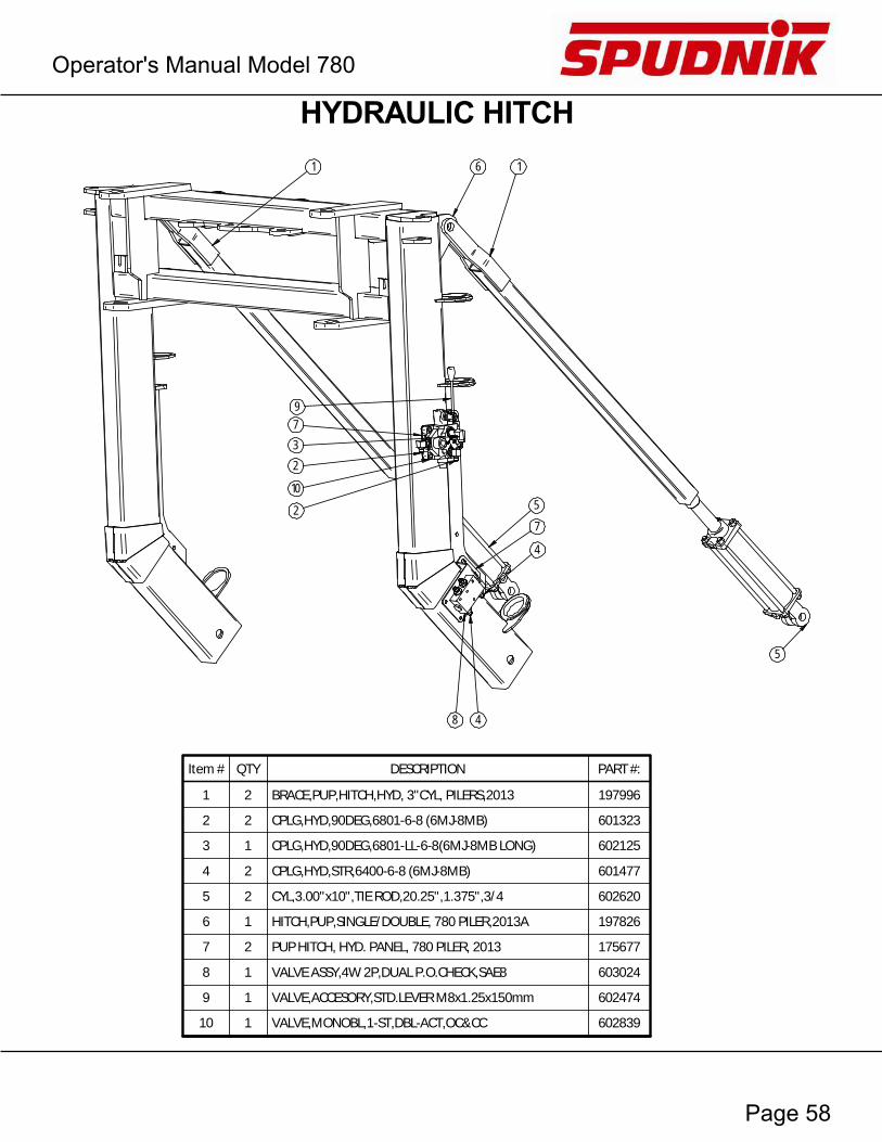
HYDRAULIC HITCH6 1
48
5
9
3
2
10
Item # QTY DESCRIPTION PART #:
1 2 BRACE,PUP,HITCH,HYD, 3"CYL, PILERS,2013 197996
2 2 CPLG,HYD,90DEG,6801-6-8 (6MJ-8MB) 601323
3 1 CPLG,HYD,90DEG,6801-LL-6-8(6MJ-8MB LONG) 602125
4 2 CPLG,HYD,STR,6400-6-8 (6MJ-8MB) 601477
5 2 CYL,3.00"x10",TIE ROD,20.25",1.375",3/4 602620
6 1 HITCH,PUP,SINGLE/DOUBLE, 780 PILER,2013A 197826
7 2 PUP HITCH, HYD. PANEL, 780 PILER, 2013 175677
8 1 VALVE ASSY,4W 2P,DUAL P.O.CHECK,SAE8 603024
9 1 VALVE,ACCESORY,STD.LEVER M8x1.25x150mm 602474
10 1 VALVE,MONOBL,1-ST,DBL-ACT,OC&CC 602839
5
1
2
7
4
7
Operator's Manual Model 780
Page 58
POST ASSEMBLY
7
1
3
9
2
2
10
8
6
5
4
Operator's Manual Model 780
Page 59
POST ASSEMBLY
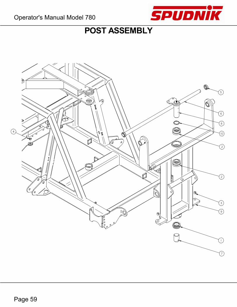
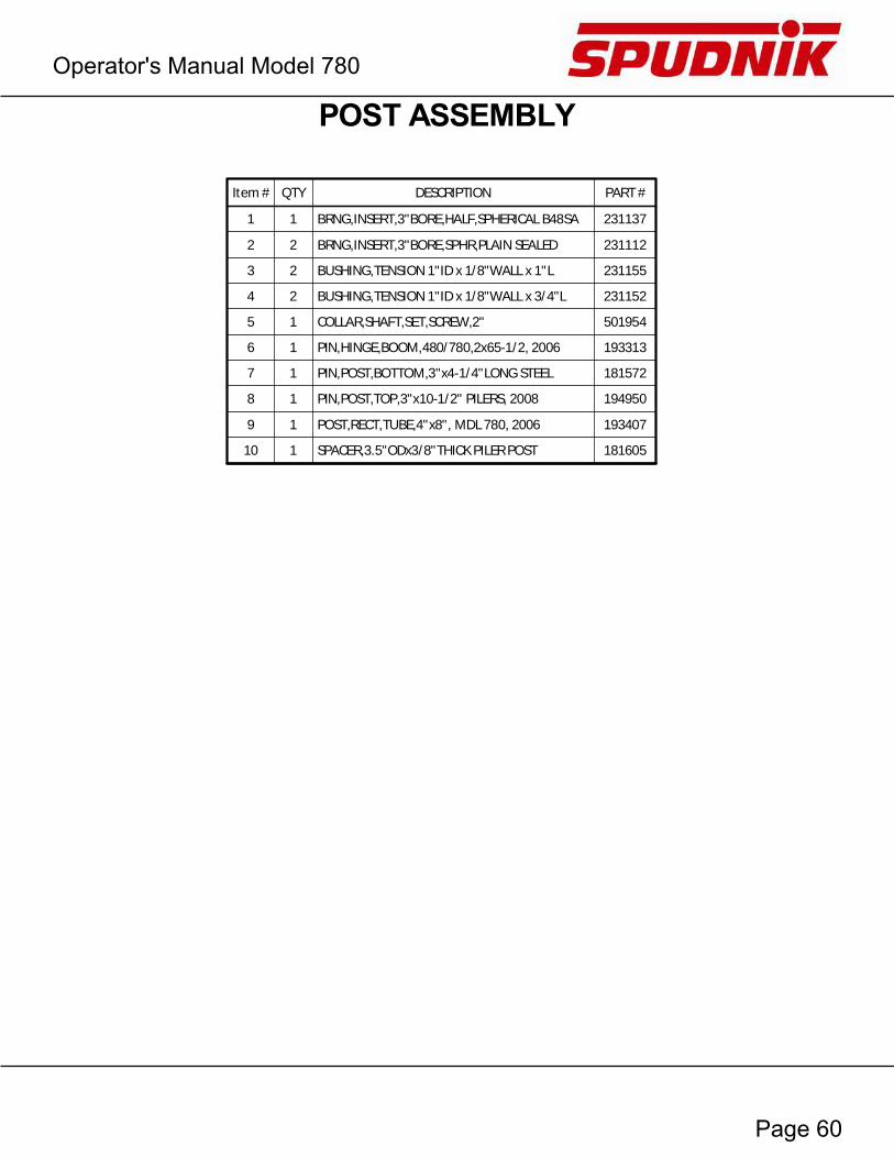
Item # QTY DESCRIPTION PART #
1 1 BRNG,INSERT,3"BORE,HALF,SPHERICAL B48SA 231137
2 2 BRNG,INSERT,3"BORE,SPHR,PLAIN SEALED 231112
3 2 BUSHING,TENSION 1"ID x 1/8"WALL x 1"L 231155
4 2 BUSHING,TENSION 1"ID x 1/8"WALL x 3/4"L 231152
5 1 COLLAR,SHAFT,SET,SCREW,2" 501954
6 1 PIN,HINGE,BOOM,480/780,2x65-1/2, 2006 193313
7 1 PIN,POST,BOTTOM,3"x4-1/4"LONG STEEL 181572
8 1 PIN,POST,TOP,3"x10-1/2" PILERS, 2008 194950
9 1 POST,RECT,TUBE,4"x8", MDL 780, 2006 193407
10 1 SPACER,3.5"ODx3/8"THICK PILER POST 181605
Operator's Manual Model 780
Page 60
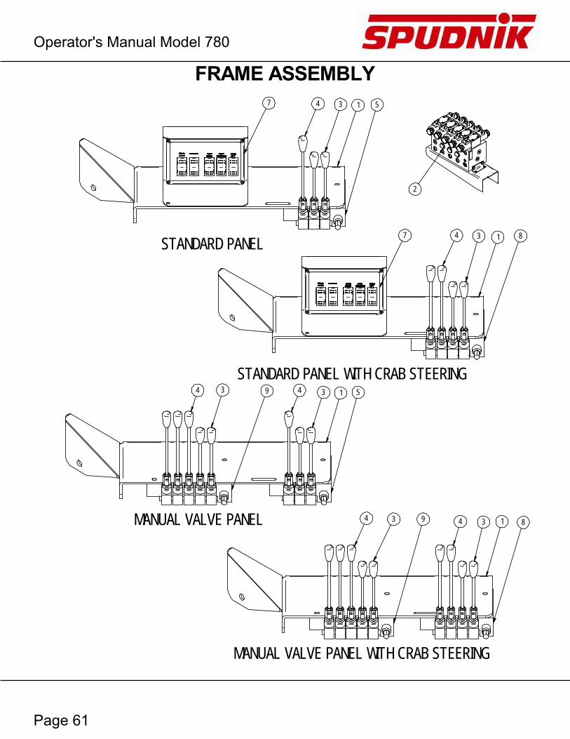
FRAME ASSEMBLY
STANDARD PANEL
1347 5
STANDARD PANEL WITH CRAB STEERING
1347 8
MANUAL VALVE PANEL
5134934
MANUAL VALVE PANEL WITH CRAB STEERING
8134934
2
Operator's Manual Model 780
Page 61
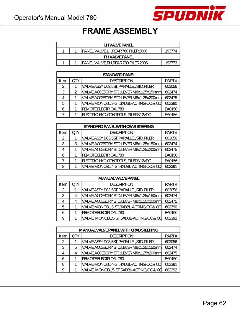
FRAME ASSEMBLY
1 1 PANEL,VALVE,LH,REAR 780 PILER 2006 193774
1 1 PANEL,VALVE,RH,REAR 780 PILER 2006 193773
Item QTY DESCRIPTION PART #2 1 VALVE ASSY,D03,5ST,PARALLEL,STD.PILER 6030563 2 VALVE,ACCESORY,STD.LEVER M8x1.25x150mm 6024744 1 VALVE,ACCESORY,STD.LEVER M8x1.25x200mm 6024755 1 VALVE,MONOBL,3-ST,3XDBL-ACTING,OC & CC 6023906 1 REMOTE ELECTRICAL 780 EA01507 1 ELECTRIC-HYD.CONTROLS, PILERS 12vDC EA0156
Item QTY DESCRIPTION PART #2 1 VALVE ASSY,D03,5ST,PARALLEL,STD.PILER 6030563 3 VALVE,ACCESORY,STD.LEVER M8x1.25x150mm 6024744 1 VALVE,ACCESORY,STD.LEVER M8x1.25x200mm 6024756 1 REMOTE ELECTRICAL 780 EA01507 1 ELECTRIC-HYD.CONTROLS, PILERS 12vDC EA01568 1 VALVE,MONOBL,4-ST,4XDBL-ACTING,OC & CC 602391
Item QTY DESCRIPTION PART #2 1 VALVE ASSY,D03,5ST,PARALLEL,STD.PILER 6030563 4 VALVE,ACCESORY,STD.LEVER M8x1.25x150mm 6024744 4 VALVE,ACCESORY,STD.LEVER M8x1.25x200mm 6024755 1 VALVE,MONOBL,3-ST,3XDBL-ACTING,OC & CC 6023906 1 REMOTE ELECTRICAL 780 EA01509 1 VALVE, MONOBL,5-ST,5XDBL-ACTING,OC & CC 602392
Item QTY DESCRIPTION PART #2 1 VALVE ASSY,D03,5ST,PARALLEL,STD.PILER 6030563 5 VALVE,ACCESORY,STD.LEVER M8x1.25x150mm 6024744 4 VALVE,ACCESORY,STD.LEVER M8x1.25x200mm 6024756 1 REMOTE ELECTRICAL 780 EA01508 1 VALVE,MONOBL,4-ST,4XDBL-ACTING,OC & CC 6023919 1 VALVE, MONOBL,5-ST,5XDBL-ACTING,OC & CC 602392
LH VALVE PANEL
RH VALVE PANEL
STANDARD PANEL
STANDARD PANEL WITH CRAB STEERING
MANUAL VALVE PANEL
MANUAL VALVE PANEL WITH CRAB STEERING
Operator's Manual Model 780
Page 62
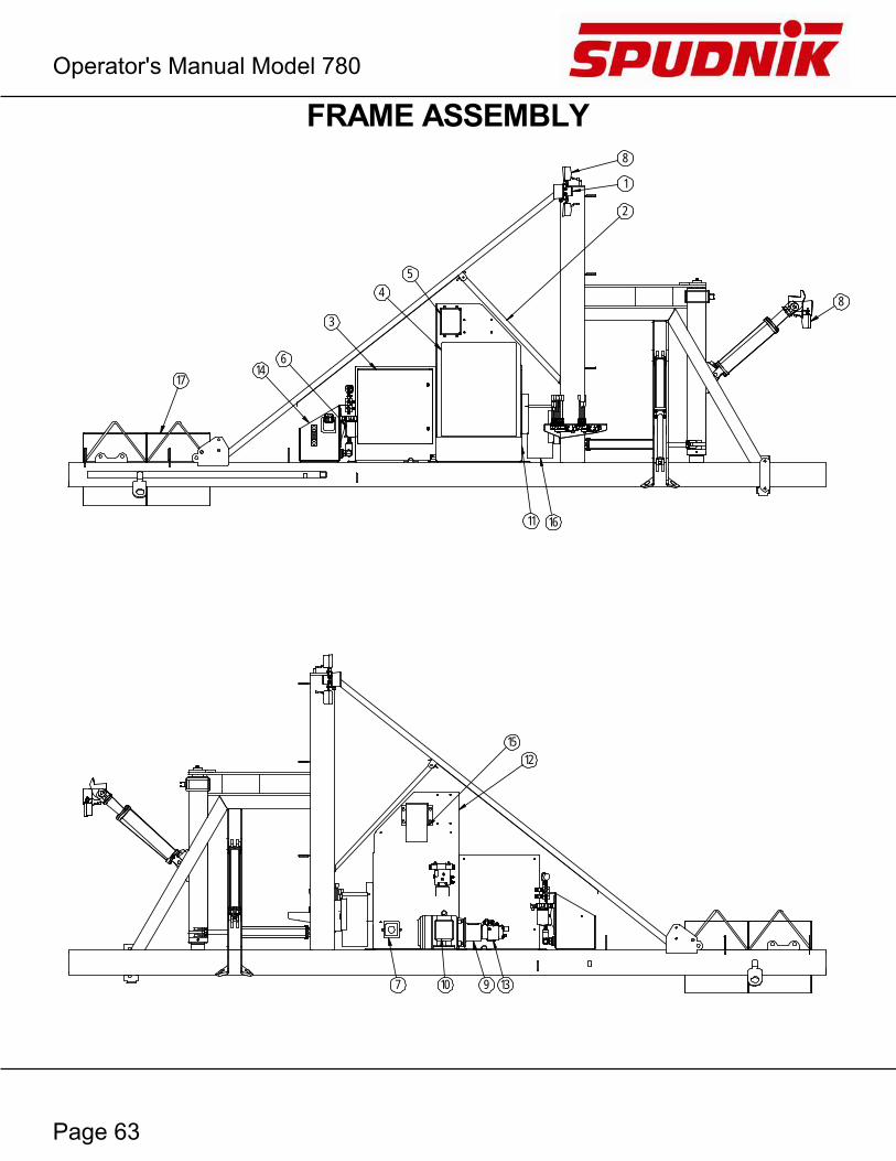
FRAME ASSEMBLY
1714
6
3
4
5
1
8
2
11 16
8
139107
15
12
Operator's Manual Model 780
Page 63
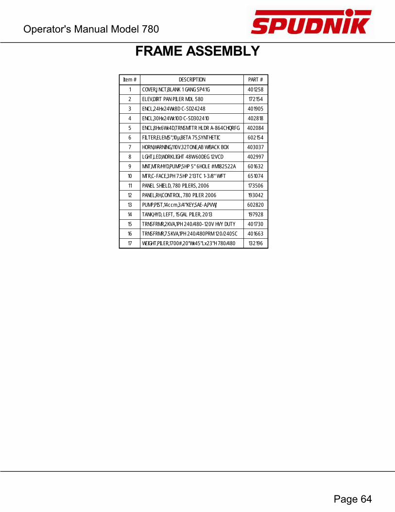
FRAME ASSEMBLY
Item # DESCRIPTION PART #
1 COVER,JNCT,BLANK 1 GANG SP41G 401258
2 ELEV,DIRT PAN PILER MDL 580 172154
3 ENCL,24Hx24Wx8D C-SD24248 401905
4 ENCL,30Hx24Wx10D C-SD302410 402818
5 ENCL,8Hx6Wx4D,TRNSMTTR HLDR A-864CHQRFG 402084
6 FILTER,ELEM,5",10µ,BETA 75,SYNTHETIC 602154
7 HORN,WARNING,110V.32TONE,AB W/BACK BOX 403037
8 LGHT,LED,WORKLIGHT 48W 60DEG 12VCD 402997
9 MNT,MTR/HYD,PUMP,5HP 5" 6HOLE #M182522A 601632
10 MTR,C-FACE,3PH 7.5HP 213TC 1-3/8" W/FT 651074
11 PANEL SHIELD, 780 PILERS, 2006 173506
12 PANEL,RH,CONTROL, 780 PILER 2006 193042
13 PUMP,PIST,14ccm,3/4"KEY,SAE-A,PVWJ 602820
14 TANK,HYD, LEFT, 15GAL PILER, 2013 197928
15 TRNSFRMR,2KVA,1PH 240/480-120V HVY DUTY 401730
16 TRNSFRMR,7.5KVA,1PH 240/480PRM 120/240SC 401663
17 WEIGHT,PILER,1700#,20"Wx45"Lx23"H 780/480 132196
Operator's Manual Model 780
Page 64
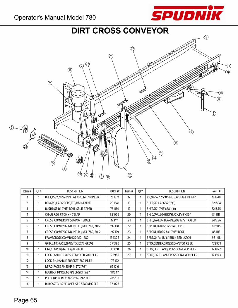
DIRT CROSS CONVEYOR
11
12
5
25
26
27
14
17
8
6
7
2
1
16
10
9
13
3
15
18
19 20
21
22 23
24
4
Item # QTY DESCRIPTION PART #:
1 1 BELT,ASSY,20"x20'3"FLAT X-CONV 780PILER 261871
2 1 BRNG,PB,1-7/16"BORE,TTB,1/7/16,FAFNIR 231241
3 1 BUSHING,P1x1-7/16" BORE SPLIT TAPER 781184
4 1 CHN,RLR,60 PITCH x 4.75LNF 351005
5 1 CROSS CONV,MOUNT,SUPPORT BRACE 173111
6 1 CROSS CONVEYOR MOUNT, LH, MDL 780, 2012 197108
7 1 CROSS CONVEYOR MOUNT, RH, MDL 780, 2012 197109
8 1 FRAME,CROSS,CONV,RH 20"x10' 780 194326
9 1 GRBX,L/F,C-FACE,26AKV 15:1 2.77 GROVE 571380
10 1 LINK,CHN,RLR,MASTER,60 PITCH 351010
11 1 LOCK HANDLE CROSS CONVEYOR 780 PILER 172986
12 1 LOCK, RH, HANDLE BRACKET 780 PILER 173102
13 1 MTR,C-FACE,3PH 1.5HP 145TC 7/8" 651016
14 1 NUBBIN,1-1/4"ODx1-3/8"LONG DT 5/8" 181047
15 1 PSC,1-1/4" BORE x 19-1/2",6-3/16" OD 781232
16 1 RLR,CAST,3-1/2" FLANGE STD STACKING RLR 321023
Item # QTY DESCRIPTION PART #:
17 1 RP,20-1/2" 2"x18"PIPE 3/4"SHAFT DT3/8" 181340
18 1 SHFT,SK 1-7/16"x26" (6) 821854
19 1 SHFT,SK,1-7/16"x28" (10) 821855
20 1 SHLD,OVAL,HINGED,W/BACK,3"x9"x30" 841112
21 1 SHLD,TAKEUP BEARING,#981572 TAKEUP 841286
22 1 SPRCKT,H60BS13x1-1/4" BORE 881105
23 1 SPRCKT,H60BS18x1-7/16" BORE 881112
24 1 SPRING,4" x 13/16" BULK BED LATCH 981148
25 1 STOP,CENTER,CROSSCONVEYOR PILER 173971
26 1 STOP,LEFT HAND,CROSSCONVEYOR PILER 173972
27 1 STOP,RIGHT HAND,CROSSCONVEYOR PILER 173973
Operator's Manual Model 780
Page 65
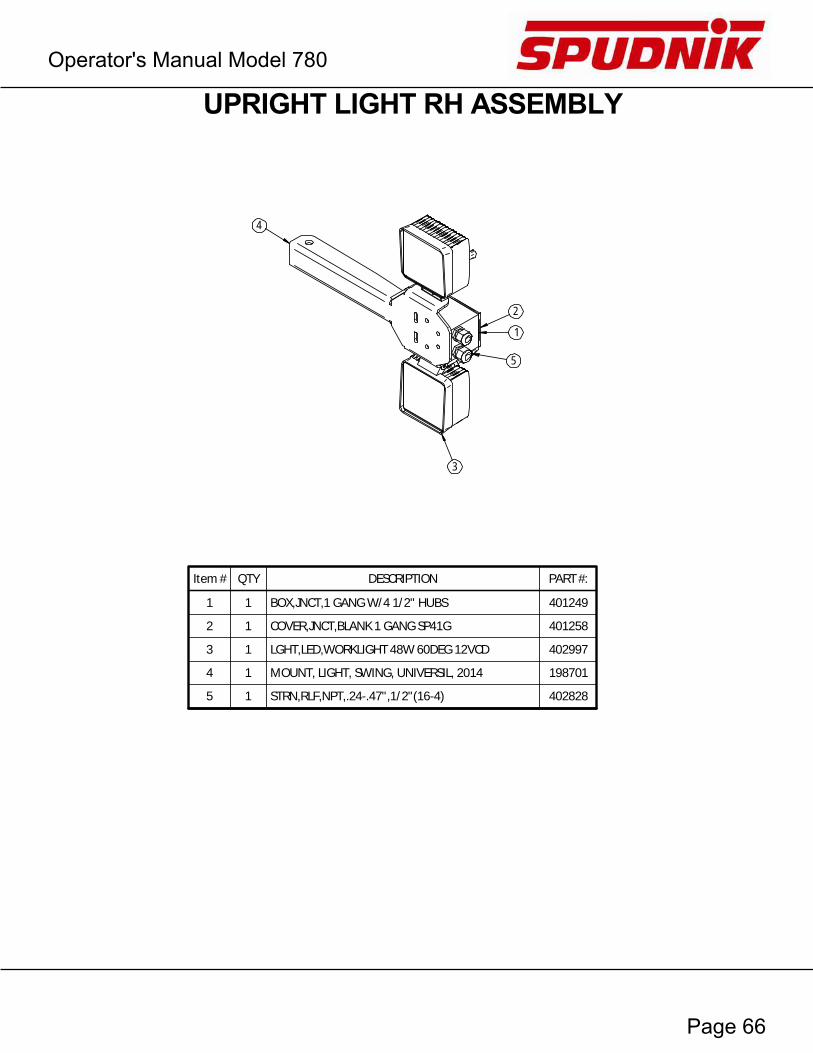
UPRIGHT LIGHT RH ASSEMBLY
4
1
2
5
3
Item # QTY DESCRIPTION PART #:
1 1 BOX,JNCT,1 GANG W/4 1/2" HUBS 401249
2 1 COVER,JNCT,BLANK 1 GANG SP41G 401258
3 1 LGHT,LED,WORKLIGHT 48W 60DEG 12VCD 402997
4 1 MOUNT, LIGHT, SWING, UNIVERSIL, 2014 198701
5 1 STRN,RLF,NPT,.24-.47",1/2"(16-4) 402828
Operator's Manual Model 780
Page 66
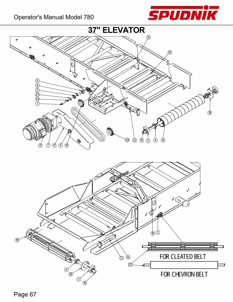
37" ELEVATOR12
18
4
18
316
21
10 2
14
711 17 9 19
15 3 4 13
18
14
22
6
8
5
23
24
1
20
FOR CHEVRON BELT
FOR CLEATED BELT25
Operator's Manual Model 780
Page 67

37" ELEVATOR
Item # DESCRIPTION PART #
1 BOLT,HEX,HD,5/8"-11UNC x 3-1/2" GR 5 501131
2 BRNG,2BOLT,FLNG,1"BORE VF2S116 BROWING 231042
3 BRNG,PB,1-7/16"BORE,TTB,1/7/16,FAFNIR 231241
4 BUSHING,P1x1-7/16" BORE SPLIT TAPER 781184
5 COLLAR,SHAFT,SET,SCREW,1-5/16" 502821
6 ELEV,HINGE,BUSH,1-1/4"BOREx.75"L 1/2"W 181888
7 GRBX,PAR,13.9:1 5HP 184TC DAVID BROWN 571130
8 HINGE PIN,1-1/4"ODx2-1/8" LG D 5/8", 780 051070
9 KNOB,CONTROL,DIE CAST DT 5/8"-11UNC 981255
10 LIFT PLATE,PILERS,ELEVATOR,2010 174697
11 MTR,C-FACE,3PH 5HP 184TC 1-1/8" W/FT 651073
12 RBO,37" 3"x35"PIPE 1-1/4" SHAFT DT 5/8" 181609
13 RLR, LDG 5" OD X 35-1/2" TL, HVY WALL, P1 781259
14 RP,37" 2"x30" PIPE 3/4" SHAFT DT 3/8" 133669
15 SHFT,DK,1-7/16"x44-1/2" (12) & (6 BLIND) 051071
16 SHFT,SK 1-7/16"x42-1/2" (6) BLIND 821849
17 SHIELD, END DRIVE,PILER,5-7HP, 780, 2013 198202
18 SHLD,TAKEUP BEARING,#981572 TAKEUP 841286
19 SPRCKT,H80BS14x1-1/4" BORE 1/4" KEYWAY 881397
20 SPRCKT,H80BS15x1-7/16"BORE 3/8" KEYWAY 881398
21 TAKE UP,LG,TUBE TYPE,1-7/16" BOT. TAP BRNG 981678
22 TAKE UP,TUBE TYPE,1-7/16" BOTTOM TAP BRNG 981572
23 WASHER,FLAT,5/8" USS ZINC PLT (13/LB) 501907
24 WASHER,LOCK,SPLIT,5/8" 501935
37" CLEATED
25 RCB,36"HD,34"RD1"x40-1/2"SHFT1"CLEAT 199563
37" CHEVRON
25 RLR,STEEL,PIPE,33",CBR 1"x40-1/2" SOLID 199561
Operator's Manual Model 780
Page 68
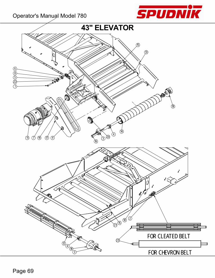
43" ELEVATOR
1
3
4
16
14
20
18
11 7 1719
6
8
5
418
3
21
102
15
22
9
15
13
12
FOR CHEVRON BELT
FOR CLEATED BELT23
Operator's Manual Model 780
Page 69

43" ELEVATOR
Item # DESCRIPTION PART #
1 BOLT,HEX,HD,5/8"-11UNC x 3-1/2" GR 5 501131
2 BRNG,2BOLT,FLNG,1"BORE VF2S116 BROWING 231042
3 BRNG,PB,1-7/16"BORE,TTB,1/7/16,FAFNIR 231241
4 BUSHING,P1x1-7/16" BORE SPLIT TAPER 781184
5 COLLAR,SHAFT,SET,SCREW,1-5/16" 502821
6 ELEV,HINGE,BUSH,1-1/4"BOREx.75"L 1/2"W 181888
7 GRBX,PAR,13.9:1 5HP 184TC DAVID BROWN 571130
8 HINGE PIN,1-1/4"ODx2-1/8" LG D 5/8", 780 051070
9 KNOB,CONTROL,DIE CAST DT 5/8"-11UNC 981255
10 LIFT PLATE,PILERS,ELEVATOR,2010 174697
11 MTR,C-FACE,3PH 5HP 184TC 1-1/8" W/FT 651073
12 PSC,TL,41-1/2" 6-3/16" O.D. 781251
13 RBO,43" 3"x41"PIPE 1-1/4"SHFT DT5/8" 133672
14 RLR,LGD,5-5/8"ODx41-1/2" TL HEAVY WALL 781250
15 RP,43" 2"x36" PIPE 3/4" SHAFT DT3/8" 133668
16 SHFT,DK,1-7/16"x50-1/2" (12) & (6 BLIND) 051067
17 SHIELD, END DRIVE,PILER,5-7HP, 780, 2013 198202
18 SHLD,TAKEUP BEARING,#981572 TAKEUP 841286
19 SPRCKT,H80BS14x1-1/4" BORE 1/4" KEYWAY 881397
20 SPRCKT,H80BS15x1-7/16"BORE 3/8" KEYWAY 881398
21 TAKE UP,LG,TUBE TYPE,1-7/16" BOT. TAP BRNG 981678
22 WASHER,FLAT,5/8" USS ZINC PLT (13/LB) 501907
43" CLEATED
23 RCB,42",HD,40"RD 1"x46/1/2" SHFT 1" CLT 199562
43" CHEVRON
23 RLR,STEEL,PIPE,39",CBR 1"x46-1/2" SOLID 199560
Operator's Manual Model 780
Page 70
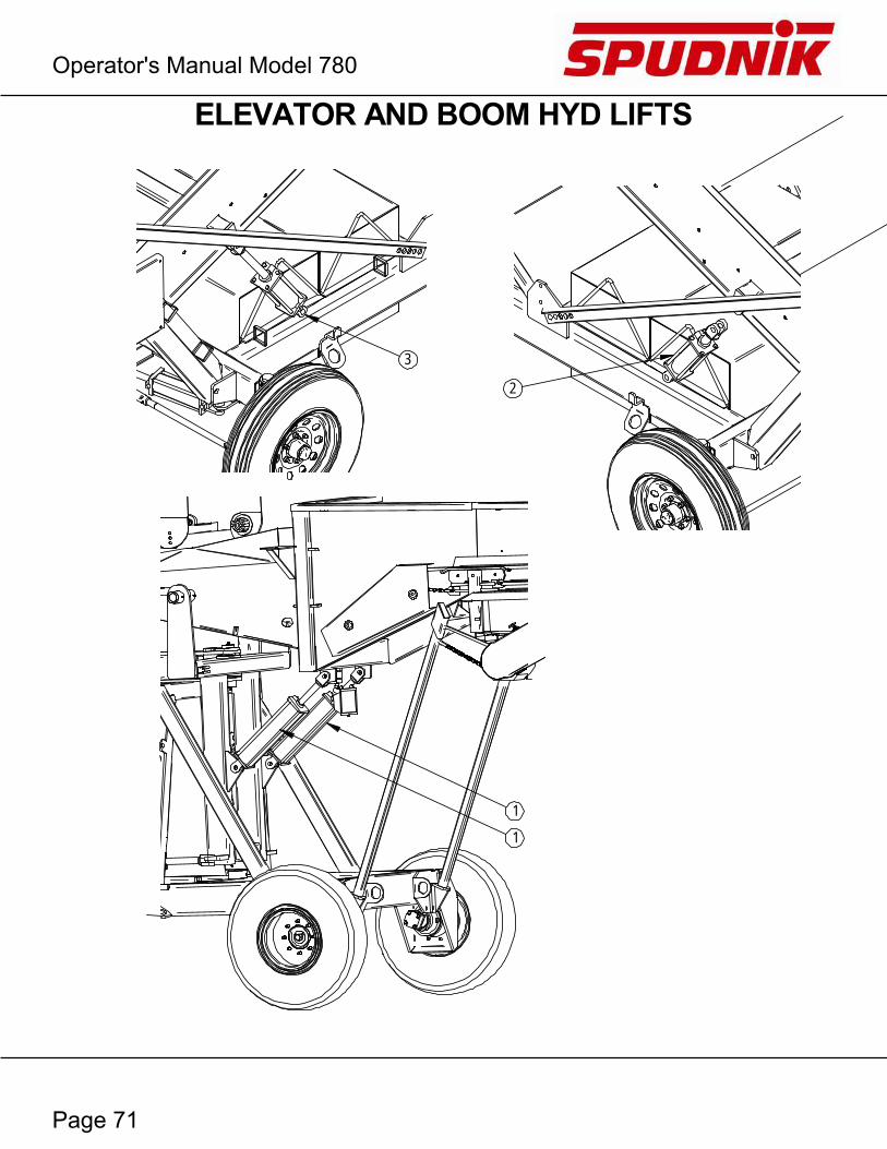
ELEVATOR AND BOOM HYD LIFTS
1
1
3
2
Operator's Manual Model 780
Page 71
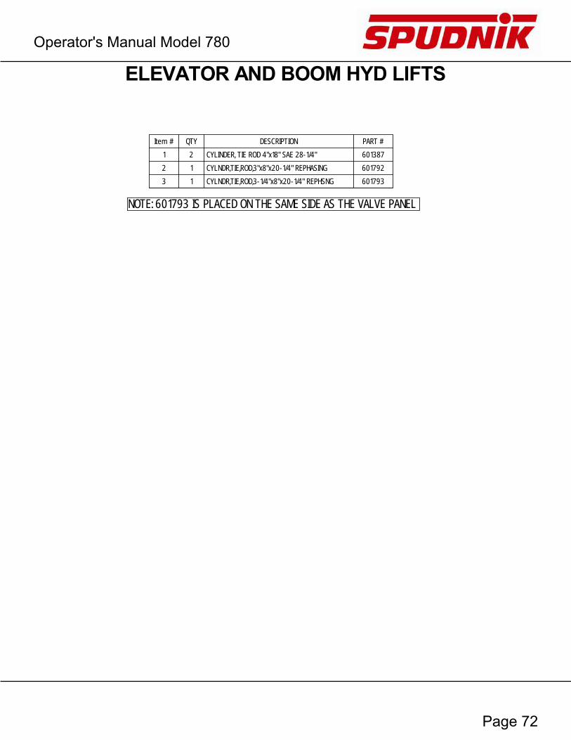
ELEVATOR AND BOOM HYD LIFTS
Item # QTY DESCRIPTION PART #
1 2 CYLINDER, TIE ROD 4"x18" SAE 28-1/4" 601387
2 1 CYLNDR,TIE,ROD,3"x8"x20-1/4" REPHASING 601792
3 1 CYLNDR,TIE,ROD,3-1/4"x8"x20-1/4" REPHSNG 601793
NOTE: 601793 IS PLACED ON THE SAME SIDE AS THE VALVE PANEL
Operator's Manual Model 780
Page 72
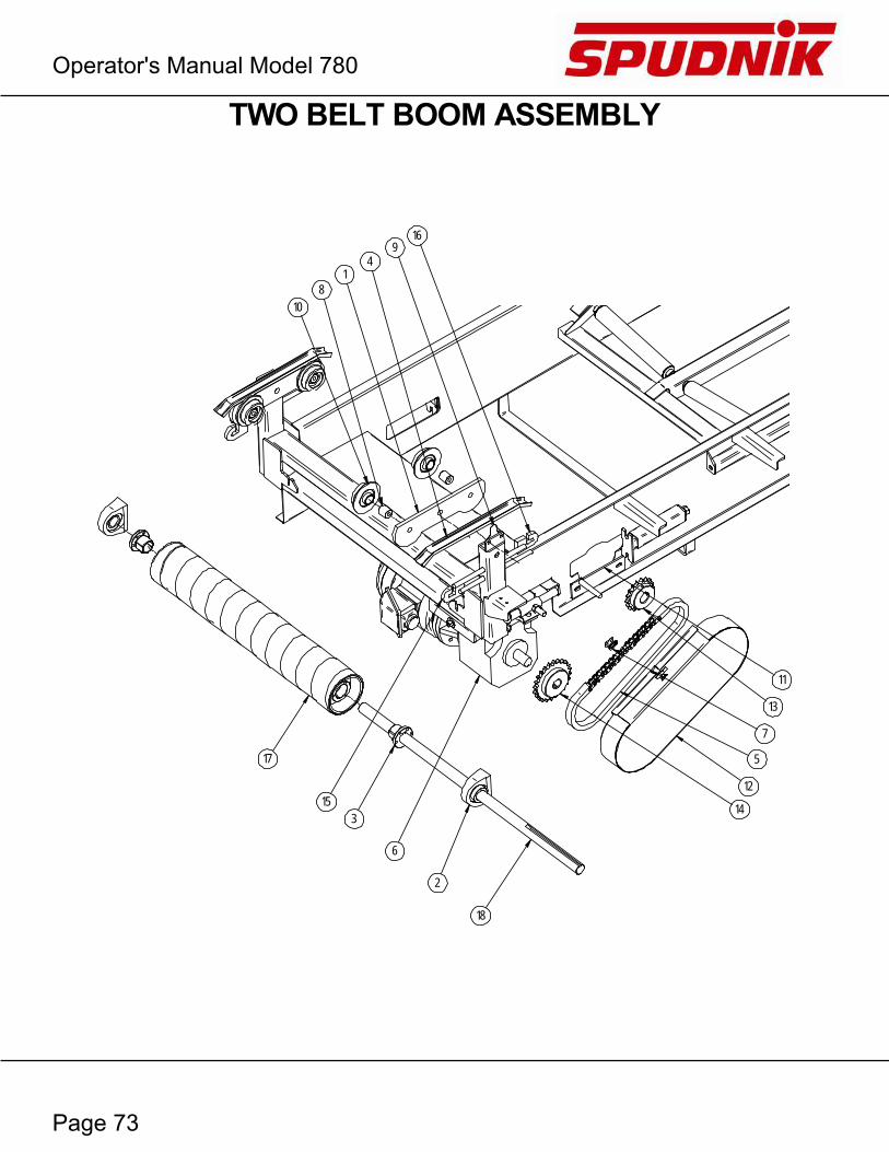
TWO BELT BOOM ASSEMBLY
12
5
7
13
14
2
3
6
15
10
81
49
16
17
18
11
Operator's Manual Model 780
Page 73
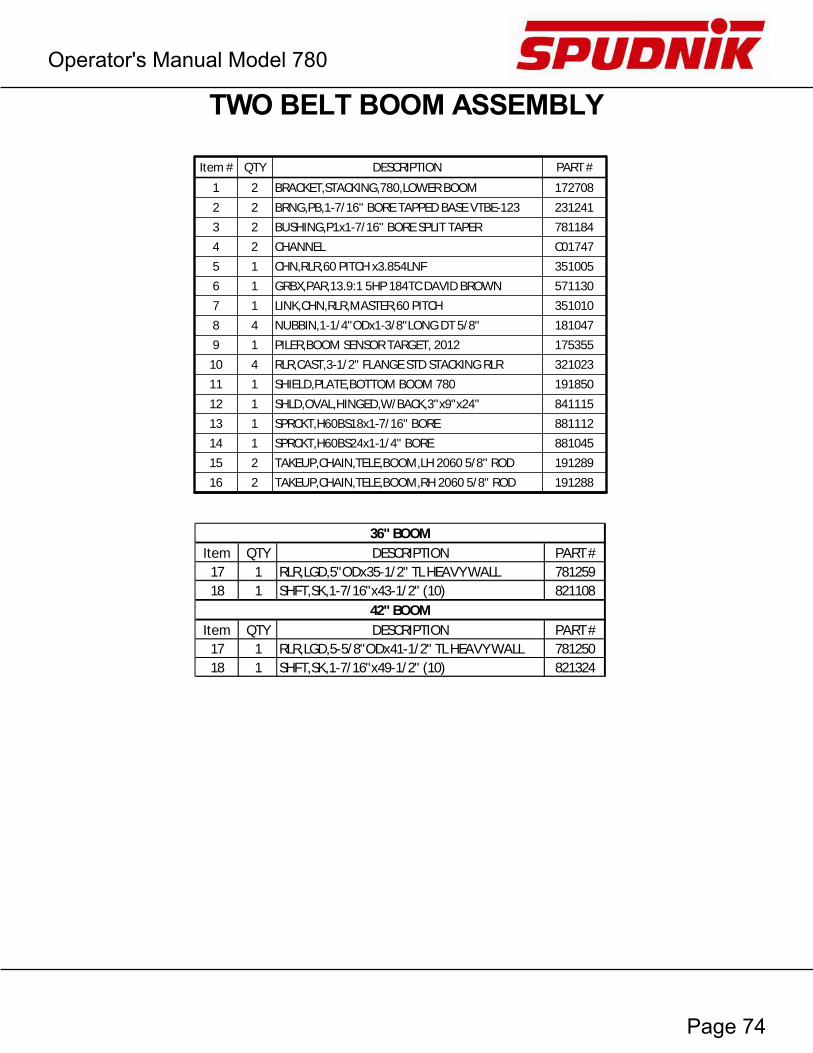
TWO BELT BOOM ASSEMBLY
Item # QTY DESCRIPTION PART #
1 2 BRACKET,STACKING,780,LOWER BOOM 1727082 2 BRNG,PB,1-7/16" BORE TAPPED BASE VTBE-123 2312413 2 BUSHING,P1x1-7/16" BORE SPLIT TAPER 7811844 2 CHANNEL C017475 1 CHN,RLR,60 PITCH x3.854LNF 3510056 1 GRBX,PAR,13.9:1 5HP 184TC DAVID BROWN 5711307 1 LINK,CHN,RLR,MASTER,60 PITCH 3510108 4 NUBBIN,1-1/4"ODx1-3/8"LONG DT 5/8" 1810479 1 PILER,BOOM SENSOR TARGET, 2012 175355
10 4 RLR,CAST,3-1/2" FLANGE STD STACKING RLR 32102311 1 SHIELD,PLATE,BOTTOM BOOM 780 19185012 1 SHLD,OVAL,HINGED,W/BACK,3"x9"x24" 84111513 1 SPRCKT,H60BS18x1-7/16" BORE 88111214 1 SPRCKT,H60BS24x1-1/4" BORE 88104515 2 TAKEUP,CHAIN,TELE,BOOM,LH 2060 5/8" ROD 19128916 2 TAKEUP,CHAIN,TELE,BOOM,RH 2060 5/8" ROD 191288
Item QTY DESCRIPTION PART #17 1 RLR,LGD,5"ODx35-1/2" TL HEAVY WALL 78125918 1 SHFT,SK,1-7/16"x43-1/2" (10) 821108
Item QTY DESCRIPTION PART #17 1 RLR,LGD,5-5/8"ODx41-1/2" TL HEAVY WALL 78125018 1 SHFT,SK,1-7/16"x49-1/2" (10) 821324
42" BOOM
36" BOOM
Operator's Manual Model 780
Page 74
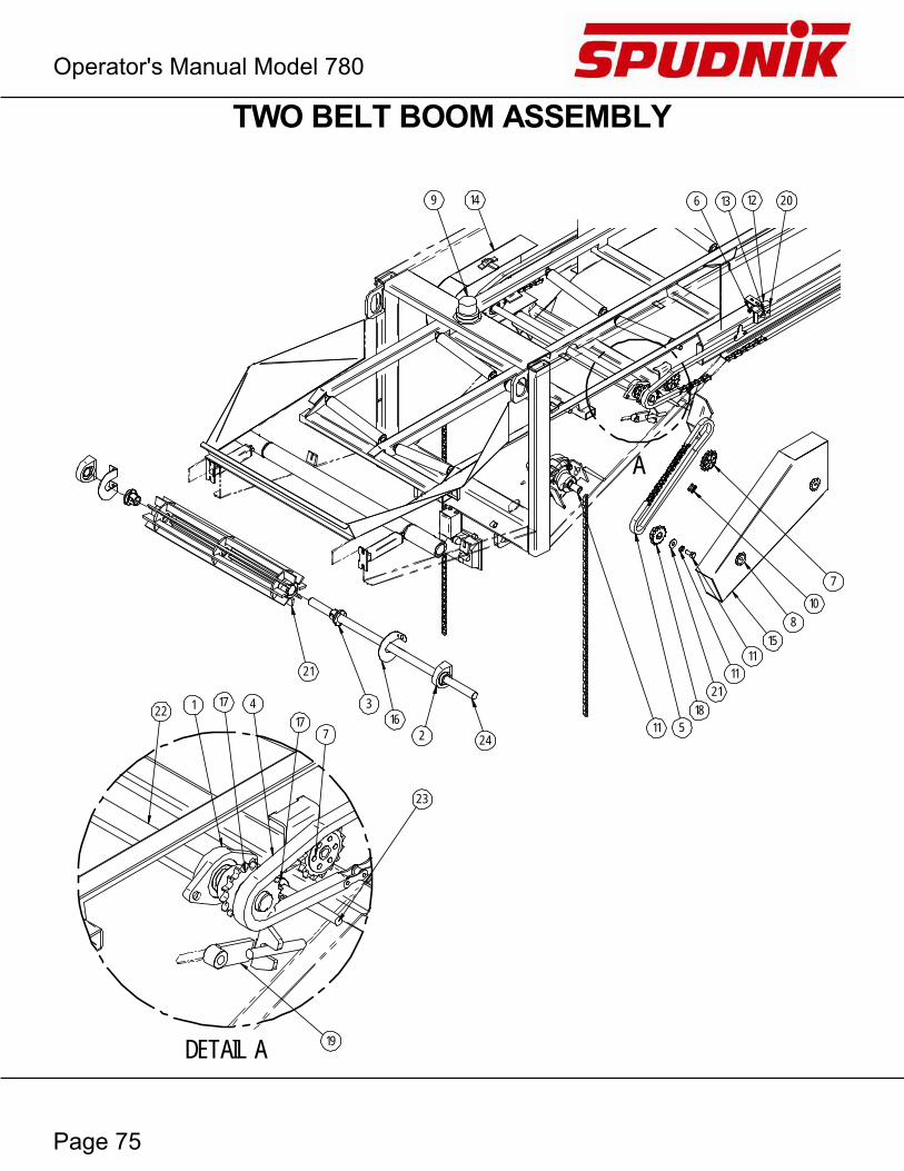
TWO BELT BOOM ASSEMBLY
15
8
11
10
7
11
21
18
5
6 1213 20
112
163
21
A
DETAIL A 19
12217 4
717
149
24
23
Operator's Manual Model 780
Page 75
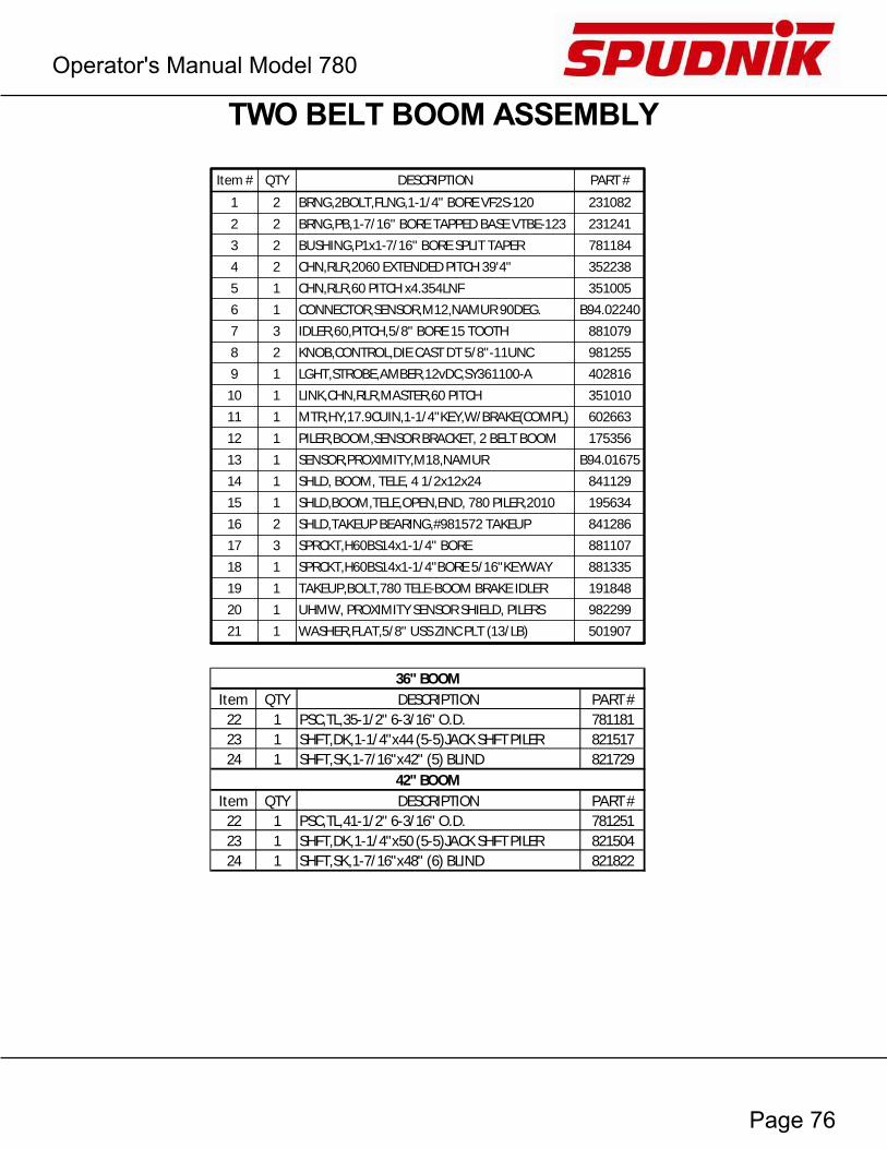
TWO BELT BOOM ASSEMBLY
Item # QTY DESCRIPTION PART #
1 2 BRNG,2BOLT,FLNG,1-1/4" BORE VF2S-120 2310822 2 BRNG,PB,1-7/16" BORE TAPPED BASE VTBE-123 2312413 2 BUSHING,P1x1-7/16" BORE SPLIT TAPER 7811844 2 CHN,RLR,2060 EXTENDED PITCH 39'4" 3522385 1 CHN,RLR,60 PITCH x4.354LNF 3510056 1 CONNECTOR,SENSOR,M12,NAMUR 90DEG. B94.022407 3 IDLER,60,PITCH,5/8" BORE 15 TOOTH 8810798 2 KNOB,CONTROL,DIE CAST DT 5/8"-11UNC 9812559 1 LGHT,STROBE,AMBER,12vDC,SY361100-A 402816
10 1 LINK,CHN,RLR,MASTER,60 PITCH 35101011 1 MTR,HY,17.9CUIN,1-1/4"KEY,W/BRAKE(COMPL) 60266312 1 PILER,BOOM,SENSOR BRACKET, 2 BELT BOOM 17535613 1 SENSOR,PROXIMITY,M18,NAMUR B94.0167514 1 SHLD, BOOM, TELE, 4 1/2x12x24 84112915 1 SHLD,BOOM,TELE,OPEN,END, 780 PILER,2010 19563416 2 SHLD,TAKEUP BEARING,#981572 TAKEUP 84128617 3 SPRCKT,H60BS14x1-1/4" BORE 88110718 1 SPRCKT,H60BS14x1-1/4"BORE 5/16"KEYWAY 88133519 1 TAKEUP,BOLT,780 TELE-BOOM BRAKE IDLER 19184820 1 UHMW, PROXIMITY SENSOR SHIELD, PILERS 98229921 1 WASHER,FLAT,5/8" USS ZINC PLT (13/LB) 501907
Item QTY DESCRIPTION PART #22 1 PSC,TL,35-1/2" 6-3/16" O.D. 78118123 1 SHFT,DK,1-1/4"x44 (5-5)JACK SHFT PILER 82151724 1 SHFT,SK,1-7/16"x42" (5) BLIND 821729
Item QTY DESCRIPTION PART #22 1 PSC,TL,41-1/2" 6-3/16" O.D. 78125123 1 SHFT,DK,1-1/4"x50 (5-5)JACK SHFT PILER 82150424 1 SHFT,SK,1-7/16"x48" (6) BLIND 821822
36" BOOM
42" BOOM
Operator's Manual Model 780
Page 76
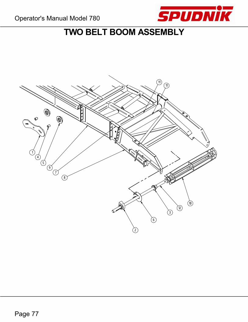
TWO BELT BOOM ASSEMBLY
1
4
5
9
7
1111
8
10
12
3
6
2
Operator's Manual Model 780
Page 77
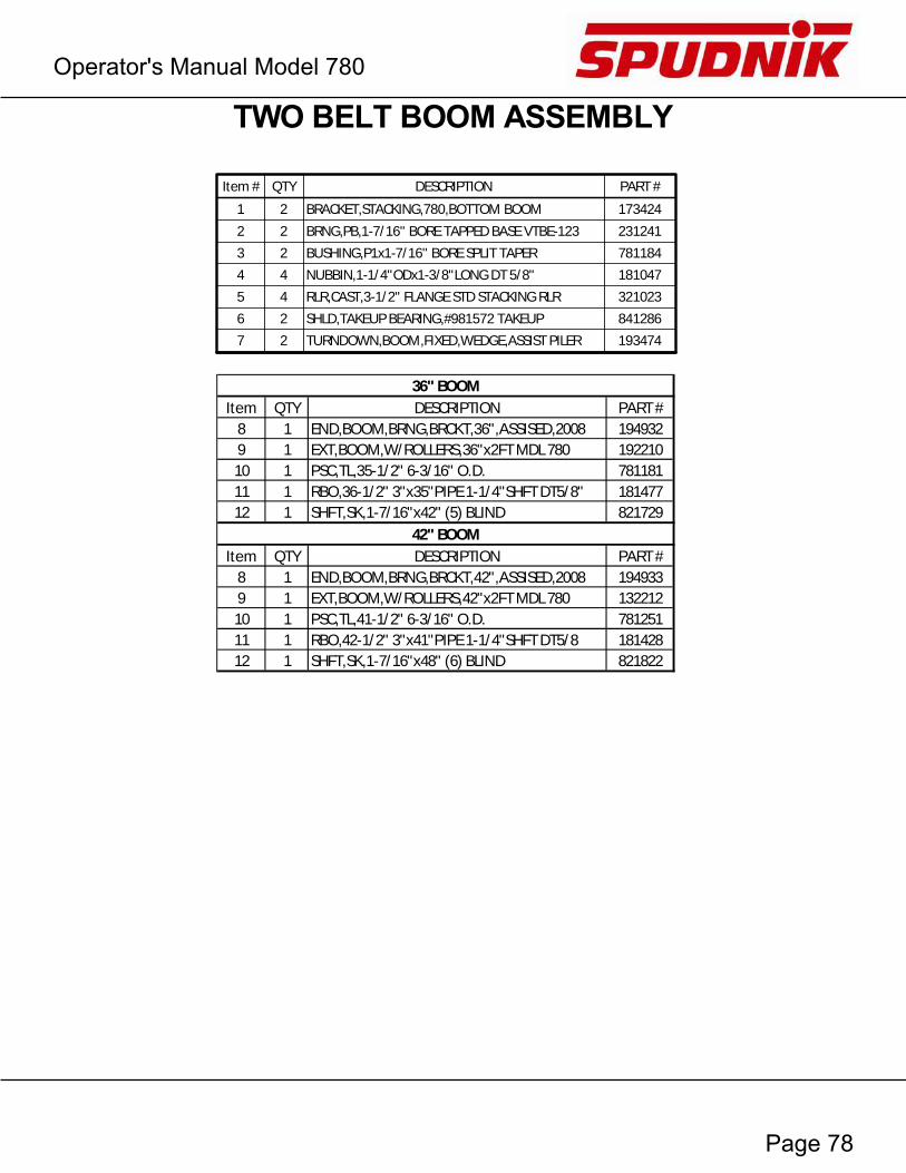
TWO BELT BOOM ASSEMBLY
Item # QTY DESCRIPTION PART #
1 2 BRACKET,STACKING,780,BOTTOM BOOM 1734242 2 BRNG,PB,1-7/16" BORE TAPPED BASE VTBE-123 2312413 2 BUSHING,P1x1-7/16" BORE SPLIT TAPER 7811844 4 NUBBIN,1-1/4"ODx1-3/8"LONG DT 5/8" 1810475 4 RLR,CAST,3-1/2" FLANGE STD STACKING RLR 3210236 2 SHLD,TAKEUP BEARING,#981572 TAKEUP 8412867 2 TURNDOWN,BOOM,FIXED,WEDGE,ASSIST PILER 193474
Item QTY DESCRIPTION PART #8 1 END,BOOM,BRNG,BRCKT,36",ASSISED,2008 1949329 1 EXT,BOOM,W/ROLLERS,36"x2FT MDL 780 19221010 1 PSC,TL,35-1/2" 6-3/16" O.D. 78118111 1 RBO,36-1/2" 3"x35"PIPE 1-1/4"SHFT DT5/8" 18147712 1 SHFT,SK,1-7/16"x42" (5) BLIND 821729
Item QTY DESCRIPTION PART #8 1 END,BOOM,BRNG,BRCKT,42",ASSISED,2008 1949339 1 EXT,BOOM,W/ROLLERS,42"x2FT MDL 780 13221210 1 PSC,TL,41-1/2" 6-3/16" O.D. 78125111 1 RBO,42-1/2" 3"x41"PIPE 1-1/4"SHFT DT5/8 18142812 1 SHFT,SK,1-7/16"x48" (6) BLIND 821822
36" BOOM
42" BOOM
Operator's Manual Model 780
Page 78
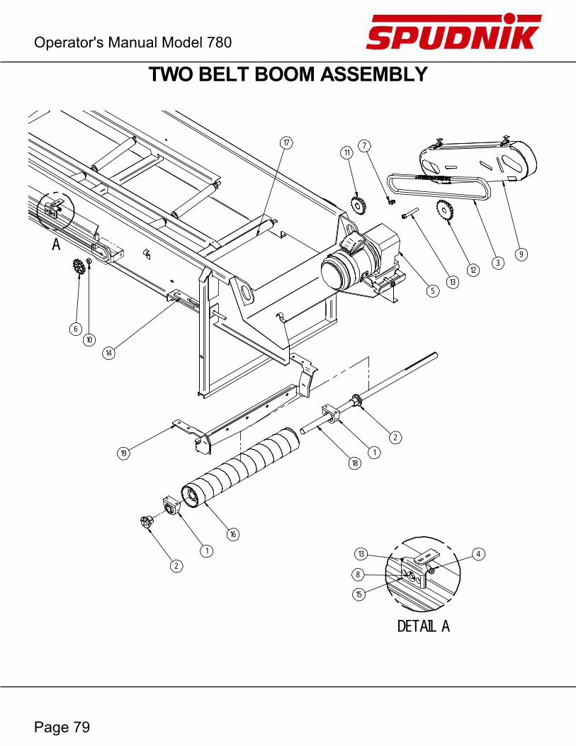
TWO BELT BOOM ASSEMBLY
2
1
16
18
1
2
19
123
9
11
5
7
15
A
DETAIL A
8
13 4
6
10
13
14
17
Operator's Manual Model 780
Page 79
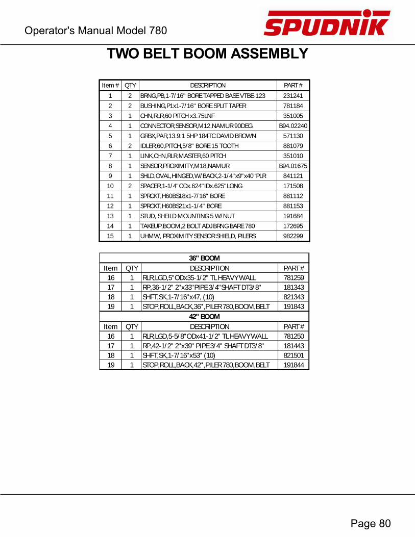
TWO BELT BOOM ASSEMBLY
Item # QTY DESCRIPTION PART #
1 2 BRNG,PB,1-7/16" BORE TAPPED BASE VTBE-123 2312412 2 BUSHING,P1x1-7/16" BORE SPLIT TAPER 7811843 1 CHN,RLR,60 PITCH x3.75LNF 3510054 1 CONNECTOR,SENSOR,M12,NAMUR 90DEG. B94.022405 1 GRBX,PAR,13.9:1 5HP 184TC DAVID BROWN 5711306 2 IDLER,60,PITCH,5/8" BORE 15 TOOTH 8810797 1 LINK,CHN,RLR,MASTER,60 PITCH 3510108 1 SENSOR,PROXIMITY,M18,NAMUR B94.016759 1 SHLD,OVAL,HINGED,W/BACK,2-1/4"x9"x40"PLR 841121
10 2 SPACER,1-1/4"ODx.624"IDx.625"LONG 17150811 1 SPRCKT,H60BS18x1-7/16" BORE 88111212 1 SPRCKT,H60BS21x1-1/4" BORE 88115313 1 STUD, SHEILD MOUNTING 5 W/NUT 19168414 1 TAKEUP,BOOM,2 BOLT ADJ BRNG BARE 780 17269515 1 UHMW, PROXIMITY SENSOR SHIELD, PILERS 982299
Item QTY DESCRIPTION PART #16 1 RLR,LGD,5"ODx35-1/2" TL HEAVY WALL 78125917 1 RP,36-1/2" 2"x33"PIPE 3/4"SHAFT DT3/8" 18134318 1 SHFT,SK,1-7/16"x47, (10) 82134319 1 STOP,ROLL,BACK,36",PILER 780,BOOM,BELT 191843
Item QTY DESCRIPTION PART #16 1 RLR,LGD,5-5/8"ODx41-1/2" TL HEAVY WALL 78125017 1 RP,42-1/2" 2"x39" PIPE 3/4" SHAFT DT3/8" 18144318 1 SHFT,SK,1-7/16"x53" (10) 82150119 1 STOP,ROLL,BACK,42",PILER 780,BOOM,BELT 191844
36" BOOM
42" BOOM
Operator's Manual Model 780
Page 80
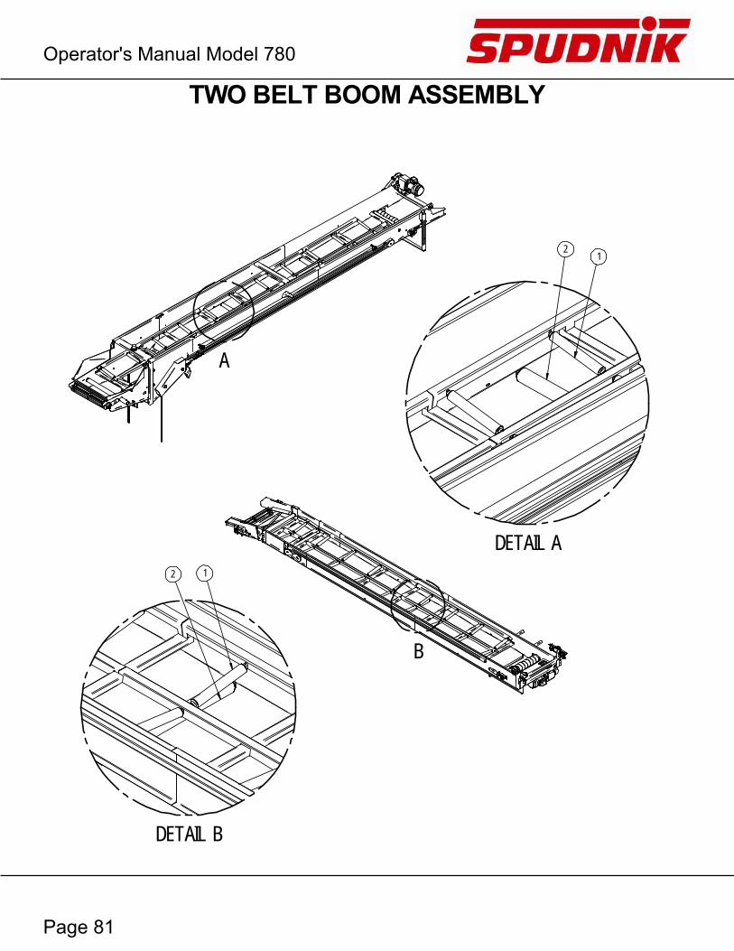
TWO BELT BOOM ASSEMBLY
A
DETAIL A
21
B
DETAIL B
12
Operator's Manual Model 780
Page 81
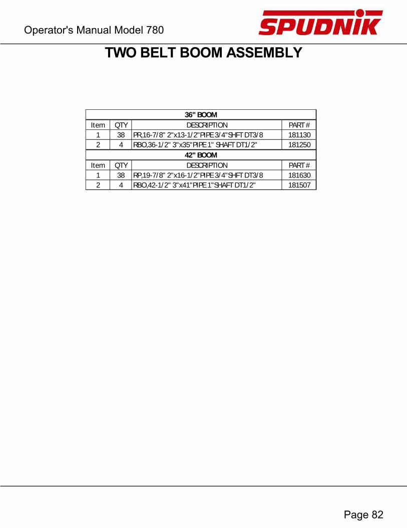
TWO BELT BOOM ASSEMBLY
Item QTY DESCRIPTION PART #1 38 PR,16-7/8" 2"x13-1/2"PIPE 3/4"SHFT DT3/8 1811302 4 RBO,36-1/2" 3"x35"PIPE 1" SHAFT DT1/2" 181250
Item QTY DESCRIPTION PART #1 38 RP,19-7/8" 2"x16-1/2"PIPE 3/4"SHFT DT3/8 1816302 4 RBO,42-1/2" 3"x41"PIPE 1"SHAFT DT1/2" 181507
36" BOOM
42" BOOM
Operator's Manual Model 780
Page 82
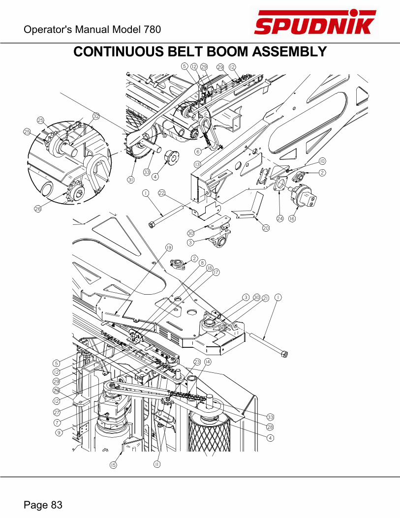
CONTINUOUS BELT BOOM ASSEMBLY
25
25
26
32
334
13
6
1 22
30
3
20
2
1624
10
12 295 29 12
2
130
19
3
5
12
29
29
12
27
7
9
14
15
23
11
4
28
33
21
31
1817
8
Operator's Manual Model 780
Page 83
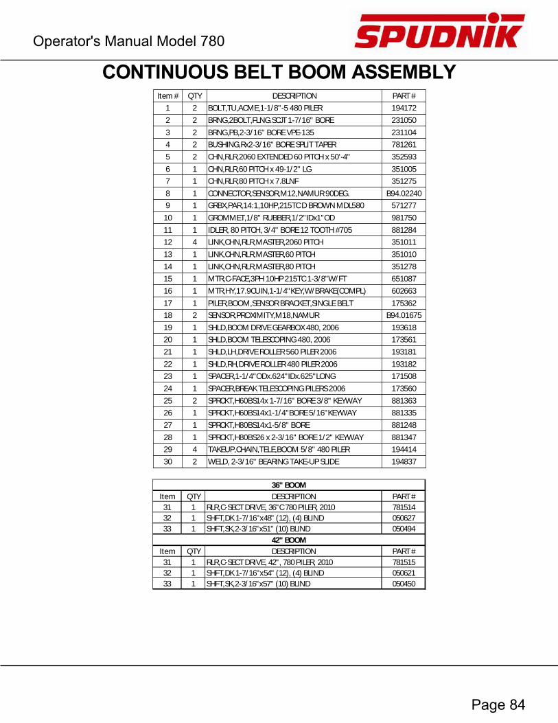
CONTINUOUS BELT BOOM ASSEMBLYItem # QTY DESCRIPTION PART #
1 2 BOLT,TU,ACME,1-1/8"-5 480 PILER 1941722 2 BRNG,2BOLT,FLNG.SCJT 1-7/16" BORE 2310503 2 BRNG,PB,2-3/16" BORE VPE-135 2311044 2 BUSHING,Rx2-3/16" BORE SPLIT TAPER 7812615 2 CHN,RLR,2060 EXTENDED 60 PITCH x 50'-4" 3525936 1 CHN,RLR,60 PITCH x 49-1/2" LG 3510057 1 CHN,RLR,80 PITCH x 7.8LNF 3512758 1 CONNECTOR,SENSOR,M12,NAMUR 90DEG. B94.022409 1 GRBX,PAR,14:1,10HP,215TC D BROWN MDL580 571277
10 1 GROMMET,1/8" RUBBER,1/2"IDx1"OD 98175011 1 IDLER, 80 PITCH, 3/4" BORE 12 TOOTH #705 88128412 4 LINK,CHN,RLR,MASTER,2060 PITCH 35101113 1 LINK,CHN,RLR,MASTER,60 PITCH 35101014 1 LINK,CHN,RLR,MASTER,80 PITCH 35127815 1 MTR,C-FACE,3PH 10HP 215TC 1-3/8"W/FT 65108716 1 MTR,HY,17.9CUIN,1-1/4"KEY,W/BRAKE(COMPL) 60266317 1 PILER,BOOM,SENSOR BRACKET,SINGLE BELT 17536218 2 SENSOR,PROXIMITY,M18,NAMUR B94.0167519 1 SHLD,BOOM DRIVE GEARBOX 480, 2006 19361820 1 SHLD,BOOM TELESCOPING 480, 2006 17356121 1 SHLD,LH,DRIVE ROLLER 560 PILER 2006 19318122 1 SHLD,RH,DRIVE ROLLER 480 PILER 2006 19318223 1 SPACER,1-1/4"ODx.624"IDx.625"LONG 17150824 1 SPACER,BREAK TELESCOPING PILERS 2006 17356025 2 SPRCKT,H60BS14x 1-7/16" BORE 3/8" KEYWAY 88136326 1 SPRCKT,H60BS14x1-1/4"BORE 5/16"KEYWAY 88133527 1 SPRCKT,H80BS14x1-5/8" BORE 88124828 1 SPRCKT,H80BS26 x 2-3/16" BORE 1/2" KEYWAY 88134729 4 TAKEUP,CHAIN,TELE,BOOM 5/8" 480 PILER 19441430 2 WELD, 2-3/16" BEARING TAKE-UP SLIDE 194837
Item QTY DESCRIPTION PART #31 1 RLR,C-SECT DRIVE, 36"C 780 PILER, 2010 78151432 1 SHFT,DK 1-7/16"x48" (12), (4) BLIND 05062733 1 SHFT,SK,2-3/16"x51" (10) BLIND 050494
Item QTY DESCRIPTION PART #31 1 RLR,C-SECT DRIVE, 42", 780 PILER, 2010 78151532 1 SHFT,DK 1-7/16"x54" (12), (4) BLIND 05062133 1 SHFT,SK,2-3/16"x57" (10) BLIND 050450
42" BOOM
36" BOOM
Operator's Manual Model 780
Page 84
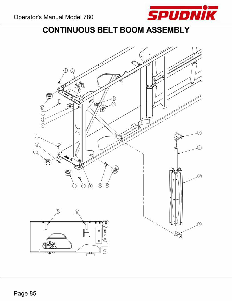
CONTINUOUS BELT BOOM ASSEMBLY
7
11
10
7
692 48
8
3
1
9
6
1
8
4
8
3 2
5 5
Operator's Manual Model 780
Page 85
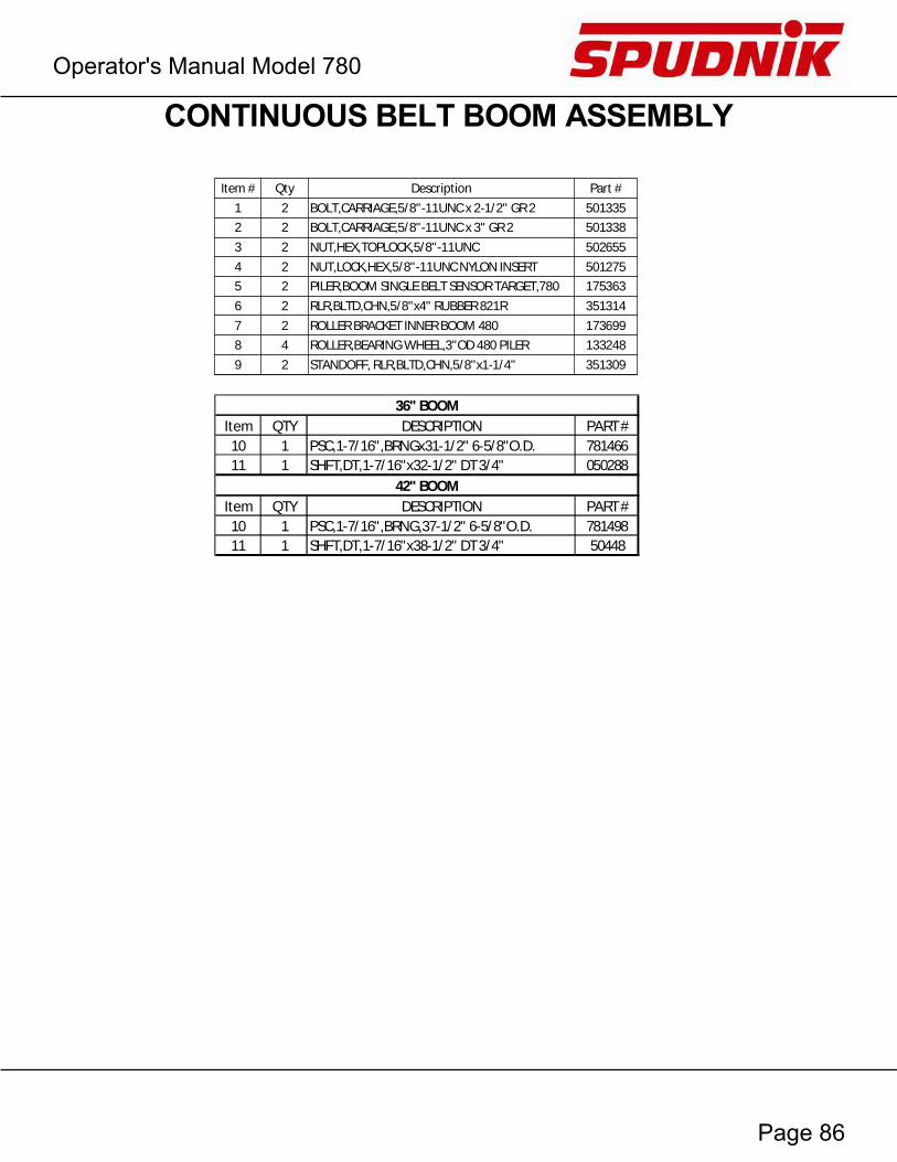
CONTINUOUS BELT BOOM ASSEMBLY
Item # Qty Description Part #1 2 BOLT,CARRIAGE,5/8"-11UNC x 2-1/2" GR 2 5013352 2 BOLT,CARRIAGE,5/8"-11UNC x 3" GR 2 5013383 2 NUT,HEX,TOPLOCK,5/8"-11UNC 5026554 2 NUT,LOCK,HEX,5/8"-11UNC NYLON INSERT 5012755 2 PILER,BOOM SINGLE BELT SENSOR TARGET,780 1753636 2 RLR,BLTD,CHN,5/8"x4" RUBBER 821R 3513147 2 ROLLER BRACKET INNER BOOM 480 1736998 4 ROLLER,BEARING WHEEL,3"OD 480 PILER 1332489 2 STANDOFF, RLR,BLTD,CHN,5/8"x1-1/4" 351309
Item QTY DESCRIPTION PART #10 1 PSC,1-7/16",BRNGx31-1/2" 6-5/8"O.D. 78146611 1 SHFT,DT,1-7/16"x32-1/2" DT 3/4" 050288
Item QTY DESCRIPTION PART #10 1 PSC,1-7/16",BRNG,37-1/2" 6-5/8"O.D. 78149811 1 SHFT,DT,1-7/16"x38-1/2" DT 3/4" 50448
42" BOOM
36" BOOM
Operator's Manual Model 780
Page 86
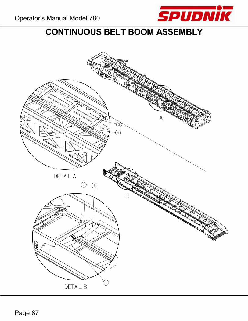
CONTINUOUS BELT BOOM ASSEMBLY
A
DETAIL A
B
DETAIL B1
2 1
3
4
Operator's Manual Model 780
Page 87
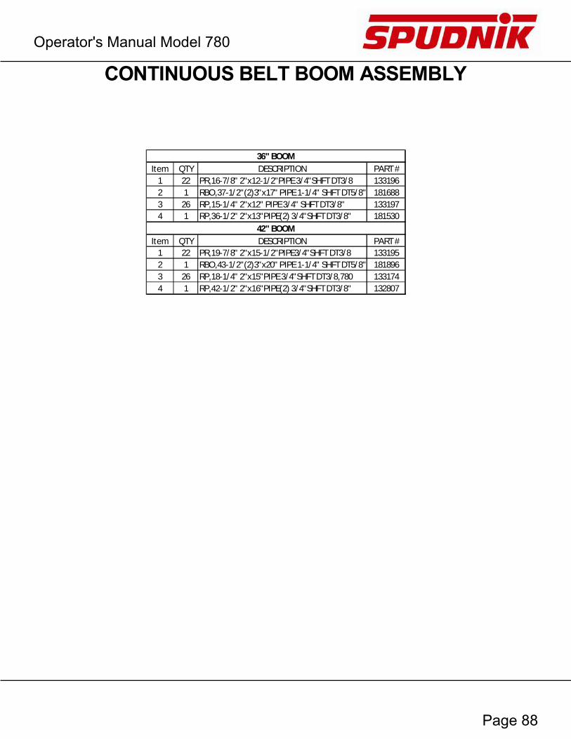
CONTINUOUS BELT BOOM ASSEMBLY
Item QTY DESCRIPTION PART #1 22 PR,16-7/8" 2"x12-1/2"PIPE 3/4"SHFT DT3/8 1331962 1 RBO,37-1/2"(2)3"x17" PIPE 1-1/4" SHFT DT5/8" 1816883 26 RP,15-1/4" 2"x12" PIPE 3/4" SHFT DT3/8" 1331974 1 RP,36-1/2" 2"x13"PIPE(2) 3/4"SHFT DT3/8" 181530
Item QTY DESCRIPTION PART #1 22 PR,19-7/8" 2"x15-1/2"PIPE3/4"SHFT DT3/8 1331952 1 RBO,43-1/2"(2)3"x20" PIPE 1-1/4" SHFT DT5/8" 1818963 26 RP,18-1/4" 2"x15"PIPE 3/4"SHFT DT3/8,780 1331744 1 RP,42-1/2" 2"x16"PIPE(2) 3/4"SHFT DT3/8" 132807
36" BOOM
42" BOOM
Operator's Manual Model 780
Page 88
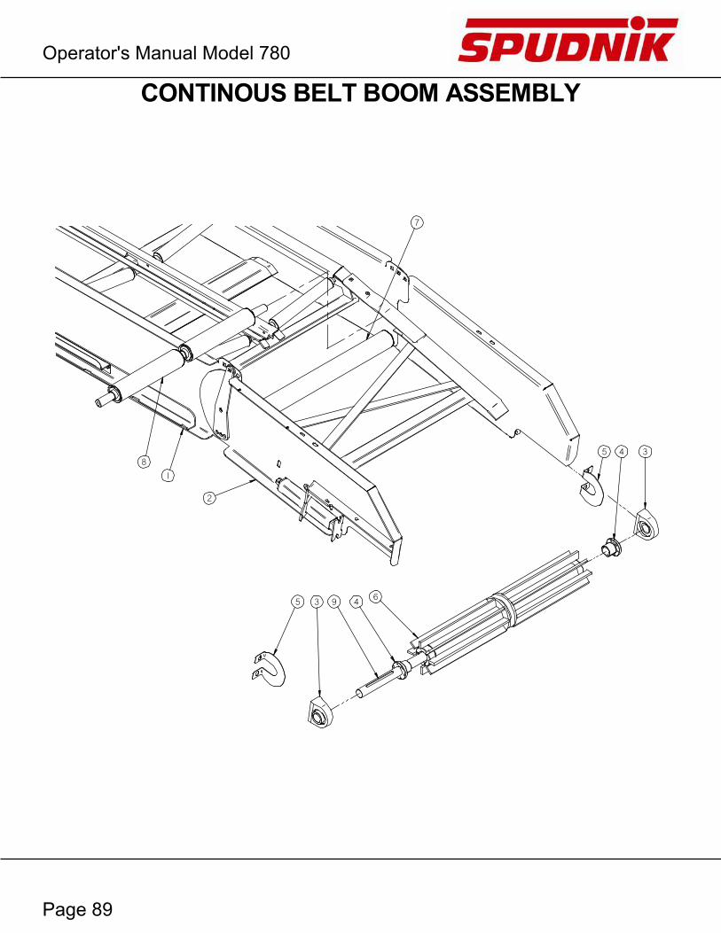
CONTINOUS BELT BOOM ASSEMBLY
8
7
1
2
5 3 9 4 6
45 3
Operator's Manual Model 780
Page 89
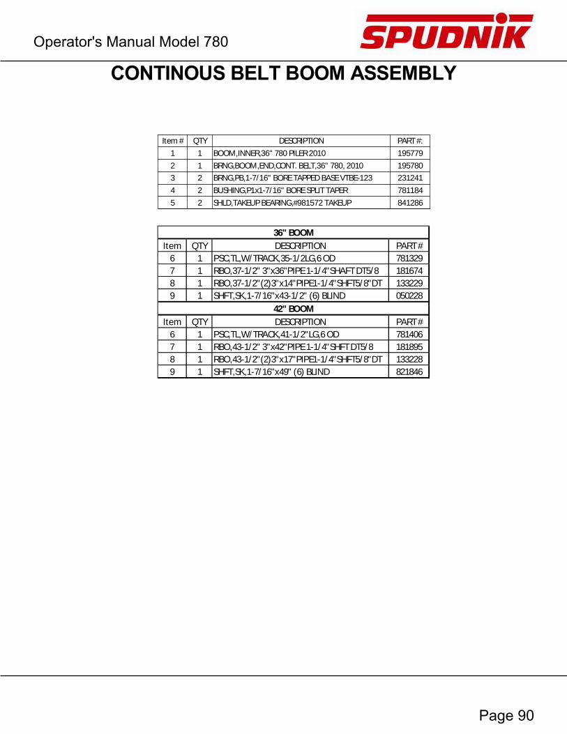
CONTINOUS BELT BOOM ASSEMBLY
Item # QTY DESCRIPTION PART #:1 1 BOOM,INNER,36" 780 PILER 2010 1957792 1 BRNG,BOOM,END,CONT. BELT,36" 780, 2010 1957803 2 BRNG,PB,1-7/16" BORE TAPPED BASE VTBE-123 2312414 2 BUSHING,P1x1-7/16" BORE SPLIT TAPER 7811845 2 SHLD,TAKEUP BEARING,#981572 TAKEUP 841286
Item QTY DESCRIPTION PART #6 1 PSC,TL,W/TRACK,35-1/2LG,6 OD 7813297 1 RBO,37-1/2" 3"x36"PIPE 1-1/4"SHAFT DT5/8 1816748 1 RBO,37-1/2"(2)3"x14"PIPE1-1/4"SHFT5/8"DT 1332299 1 SHFT,SK,1-7/16"x43-1/2" (6) BLIND 050228
Item QTY DESCRIPTION PART #6 1 PSC,TL,W/TRACK,41-1/2"LG,6 OD 7814067 1 RBO,43-1/2" 3"x42"PIPE 1-1/4"SHFT DT5/8 1818958 1 RBO,43-1/2"(2)3"x17"PIPE1-1/4"SHFT5/8"DT 1332289 1 SHFT,SK,1-7/16"x49" (6) BLIND 821846
36" BOOM
42" BOOM
Operator's Manual Model 780
Page 90
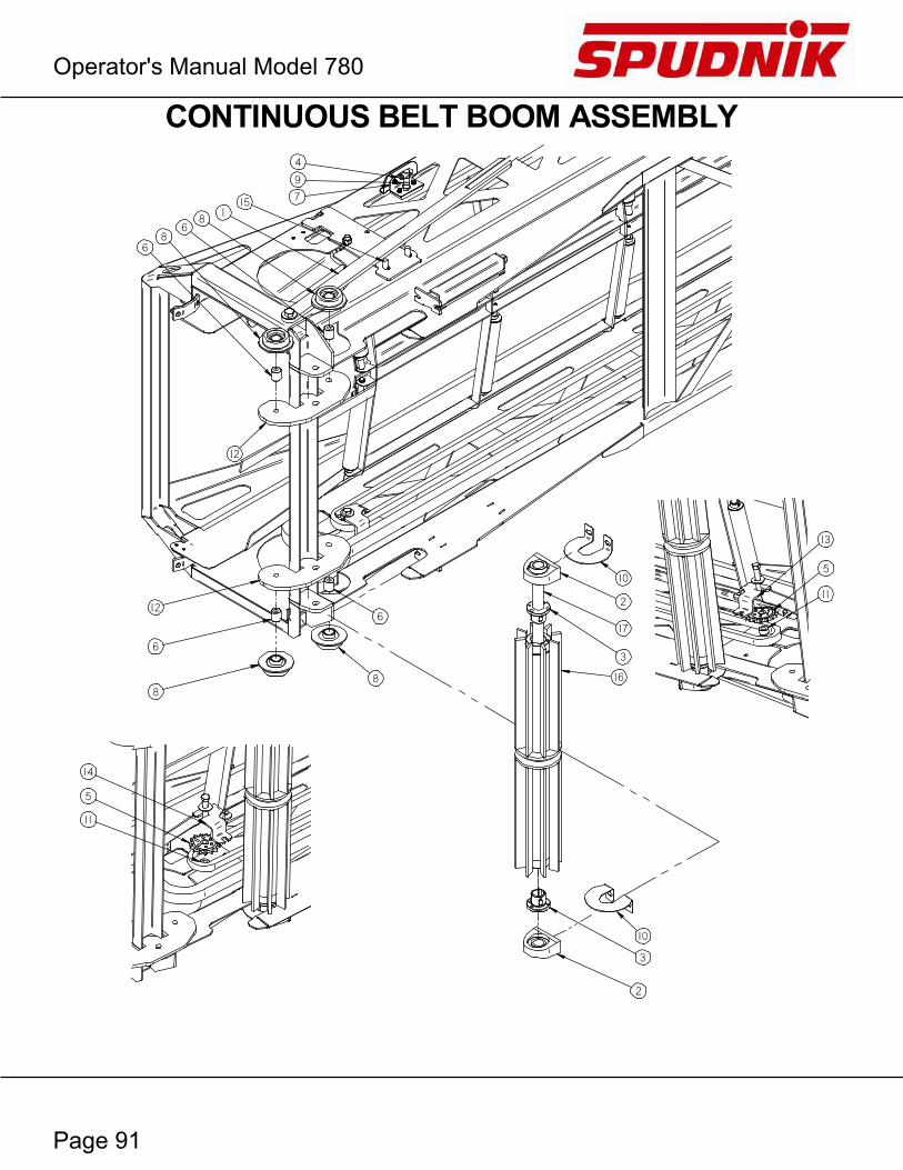
CONTINUOUS BELT BOOM ASSEMBLY
12
8
2
3
10
11
5
14
3
17
2
10
68
86
12
6
8
6
11
5
13
16
17
9
4
15
Operator's Manual Model 780
Page 91
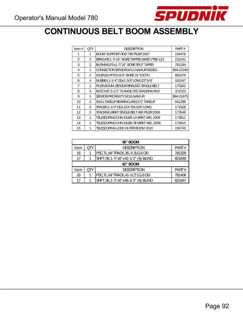
CONTINUOUS BELT BOOM ASSEMBLY
Item # QTY DESCRIPTION PART #1 1 BOOM SUPPORT ROD 780 PILER 2007 1944782 2 BRNG,PB,1-7/16" BORE TAPPED BASE VTBE-123 2312413 2 BUSHING,P1x1-7/16" BORE SPLIT TAPER 7811844 1 CONNECTOR,SENSOR,M12,NAMUR 90DEG. B94.022405 2 IDLER,60,PITCH,5/8" BORE 15 TOOTH 8810796 4 NUBBIN,1-1/4"ODx1-3/8"LONG DT 5/8" 1810477 1 PILER,BOOM,SENSOR BRACKET,SINGLE BELT 1753628 4 RLR,CAST,3-1/2" FLANGE STD STACKING RLR 3210239 1 SENSOR,PROXIMITY,M18,NAMUR B94.01675
10 2 SHLD,TAKEUP BEARING,#981572 TAKEUP 84128611 2 SPACER,1-1/4"ODx.624"IDx.625"LONG 17150812 2 STACKING BRKT SINGLE BELT 480 PILER 2006 17354813 1 TELESCOPING CHN IDLER, LH BRKT 480, 2006 17381114 1 TELESCOPING CHN IDLER, RH BRKT 480, 2006 17381015 1 TELESCOPING LOCK OUTER BOOM 2010 195743
Item QTY DESCRIPTION PART #16 1 PSC,TL,W/TRACK,35-1/2LG,6 OD 78132917 1 SHFT,SK,1-7/16"x42-1/2" (6) BLIND 821849
Item QTY DESCRIPTION PART #16 1 PSC,TL,W/TRACK,41-1/2"LG,6 OD 78140617 1 SHFT,SK,1-7/16"x48-1/2" (6) BLIND 821847
36" BOOM
42" BOOM
Operator's Manual Model 780
Page 92
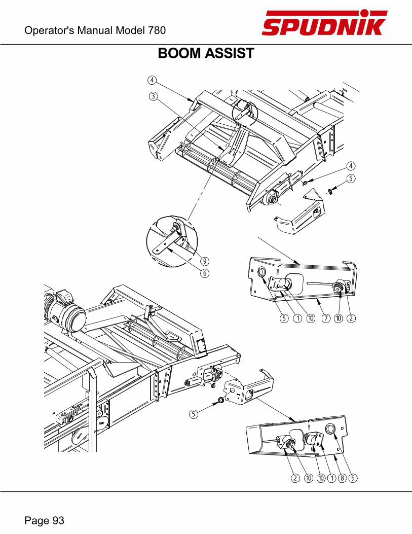
BOOM ASSIST
1015 7 10 2
5
4
58110102
3
9
6
5
4
Operator's Manual Model 780
Page 93
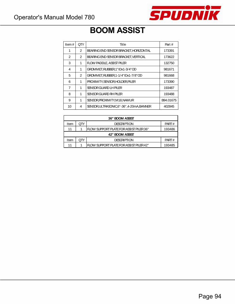
BOOM ASSISTItem # QTY Title Part #
1 2 BEARING END SENSOR BRACKET,HORIZONTAL 173391
2 2 BEARING END SENSOR BRACKET,VERTICAL 173622
3 1 FLOW PADDLE, ASSIST PILER 132750
4 1 GROMMET,RUBBER,1"IDx1-3/4"OD 981671
5 2 GROMMET,RUBBER,1-1/4"IDx1-7/8"OD 981668
6 1 PROXIMITY,SENSOR,HOLDER,PILER 173390
7 1 SENSOR GUARD LH PILER 193487
8 1 SENSOR GUARD RH PILER 193488
9 1 SENSOR,PROXIMITY,M18,NAMUR B94.01675
10 4 SENSOR,ULTRASONIC,6"-36",4-20mA,BANNER 402845
Item QTY DESCRIPTION PART #11 1 FLOW SUPPORT PLATE FOR ASSIST PILER 36" 193486
Item QTY DESCRIPTION PART #11 1 FLOW SUPPORT PLATE FOR ASSIST PILER 42" 193485
36" BOOM ASSIST
42" BOOM ASSIST
Operator's Manual Model 780
Page 94
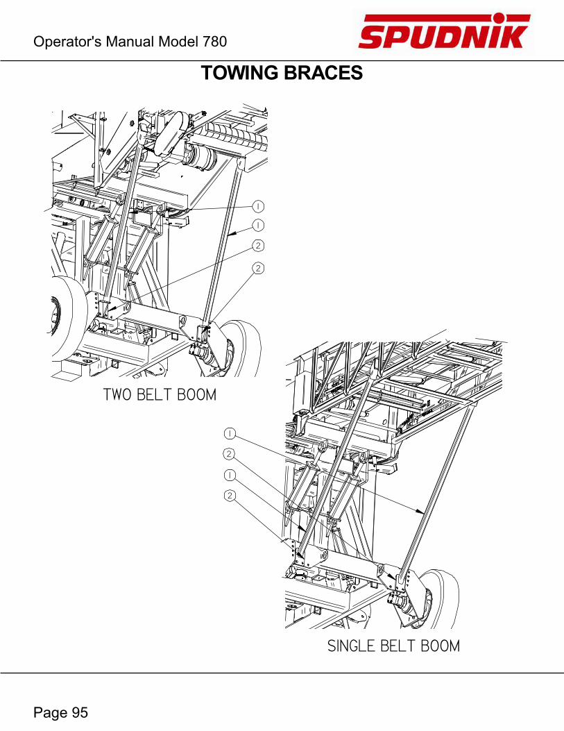
TOWING BRACES
TWO BELT BOOM
SINGLE BELT BOOM
2
1
1
2
2
1
2
1
Operator's Manual Model 780
Page 95
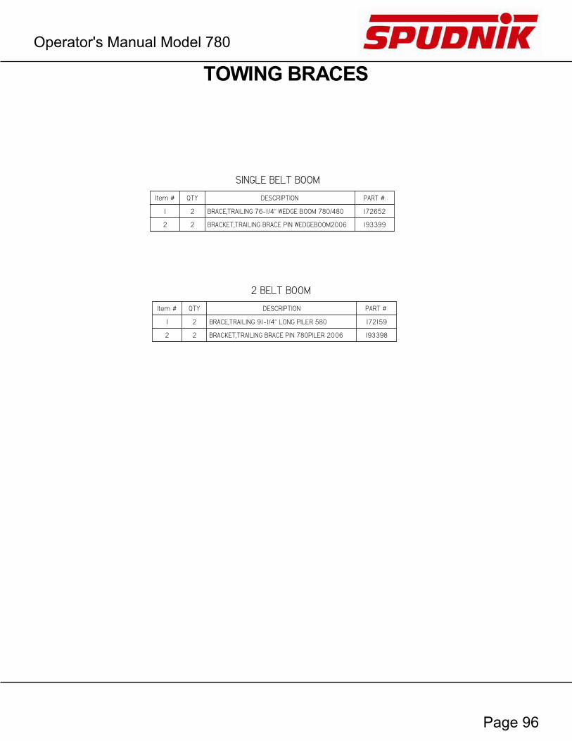
TOWING BRACES
Item # QTY DESCRIPTION PART #:
1 2 BRACE,TRAILING 76-1/4" WEDGE BOOM 780/480 172652
2 2 BRACKET,TRAILING BRACE PIN WEDGEBOOM2006 193399
Item # QTY DESCRIPTION PART #:
1 2 BRACE,TRAILING 91-1/4" LONG PILER 580 172159
2 2 BRACKET,TRAILING BRACE PIN 780PILER 2006 193398
SINGLE BELT BOOM
2 BELT BOOM
Operator's Manual Model 780
Page 96
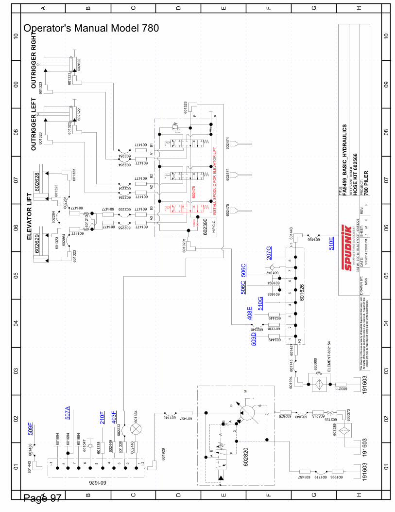
01 01
02 02
03 03
04 04
05 05
06 06
07 07
08 08
09 09
10 10
AA
BB
CC
DD
EE
FF
GG
HH
584
W. 1
00 N
. BLA
CKFO
OT,
ID 8
3221
DR
AW
N B
Y:
DA
TE
:S
HE
ET
:R
EV
:
TIT
LE
RE
LE
VA
NT
BO
M #
PR
OJE
CT
:M
SS
5/19
/201
4 3:
18:0
8 PM
1o
f0
0
FA
545
9_B
AS
IC_H
YD
RA
UL
ICS
HO
SE
KIT
60
2566
780
PIL
ER
Th
is d
raw
ing
in
th
e s
ole
pro
pe
rty
of
Sp
ud
nik
Eq
uim
en
t C
om
pa
ny
, L
LC
.A
ll ri
gh
ts o
f th
e d
esi
gn
an
d/o
f in
ve
nti
on
are
re
se
rve
d.
No
par
t o
f th
isd
ocu
me
nt
may
be
re
pro
du
ce
d w
ith
ou
t p
rio
r w
ritt
en
pe
rmis
sio
n.
191
603
601993601719601457
602875 601043 603213602155
603
373
603
289
191
603
601457601745
601
928
4 1235678I-1
I-2
601626
602
446
601
864
601
338
602
449
601
338
601
047601
694
601
443
601
694
601
694
601
486
403
F
191
603
603211
603
000
EL
EM
EN
T-6
02
154
601
994
601
457
41
23
56
78
I-1
I-2
601
626
601
745
601
443
601486
602449
602449
601338
601694
601694
601047
207
G601
323
602240
601477
601477
601477
601477
601477
601477
601
323
602
232
602255
602255
601477
601477
601
213
601477
601477602
281
602
629
602
628
601
323
601
323
601
323
601
323
602
864
602
284
210
F
602254
602
622
602
622
601
323 6
013
23
601
323 6
013
23
OU
TR
IGG
ER
LE
FT
OU
TR
IGG
ER
RIG
HT
EL
EV
AT
OR
LIF
T
408
E
510
E
509
F
509
D5
10G
506
C5
06C
A
P
B
AA
AB
SBX
L
M6
028
20
507
A
602254
602284
602284
602
475
602
474
602
474
602
246
T
B3
A3
B2
A2
B1
A1
P
H.P
.C.O
.P
INS
TA
LL
SP
OO
L C
FO
R E
LE
VA
TO
R L
IFT
602
476
602
390
Operator's Manual Model 780
Page 97
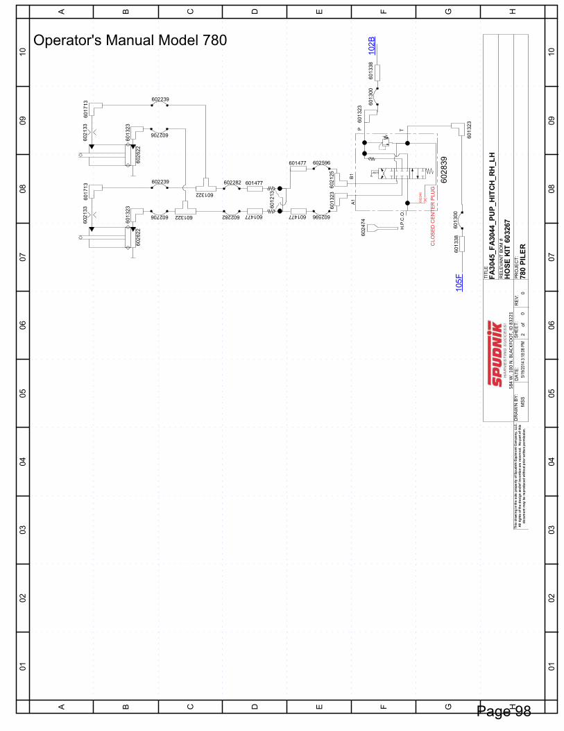
01 01
02 02
03 03
04 04
05 05
06 06
07 07
08 08
09 09
10 10
AA
BB
CC
DD
EE
FF
GG
HH
584
W. 1
00 N
. BLA
CKFO
OT,
ID 8
3221
DR
AW
N B
Y:
DA
TE
:S
HE
ET
:R
EV
:
TIT
LE
RE
LE
VA
NT
BO
M #
PR
OJE
CT
:M
SS
5/19
/201
4 3:
18:0
8 PM
2o
f0
0
FA
304
5_F
A30
44_P
UP
_HIT
CH
_R
H_L
H
HO
SE
KIT
60
3267
780
PIL
ER
Th
is d
raw
ing
in
th
e s
ole
pro
pe
rty
of
Sp
ud
nik
Eq
uim
en
t C
om
pa
ny
, L
LC
.A
ll ri
gh
ts o
f th
e d
esi
gn
an
d/o
f in
ve
nti
on
are
re
se
rve
d.
No
par
t o
f th
isd
ocu
me
nt
may
be
re
pro
du
ce
d w
ith
ou
t p
rio
r w
ritt
en
pe
rmis
sio
n.
601
338
601
323
601
323
602
125
602596
602596
601
213
601477
601477
601477601477
602282
602282
601322
601322
602
622
601
323
602
133
601
713
602706
602239
602
622
601
323
602
133
601
713
602706
602239
105
F6
013
00
602
474
H.P
.C.O
.
P T
B1
A1
602
839
CL
OS
ED
CE
NT
ER
PL
UG
602
246
601
323
601
338
102
B6
013
00
Operator's Manual Model 780
Page 98
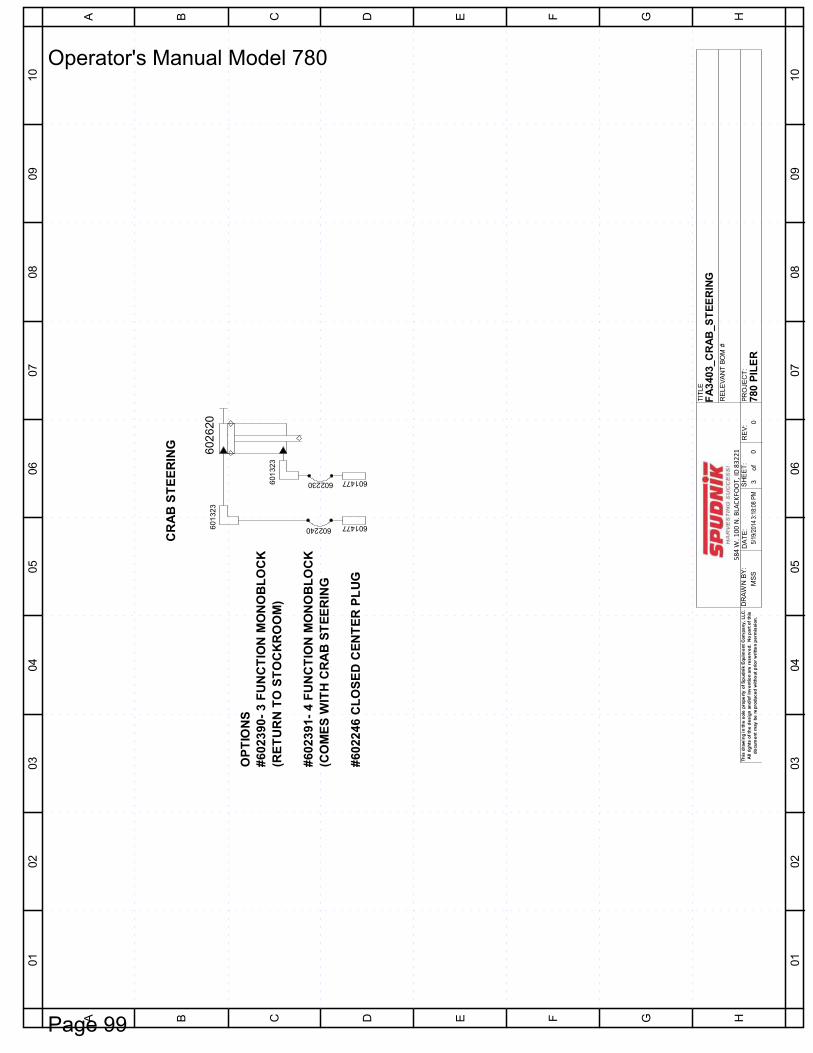
01 01
02 02
03 03
04 04
05 05
06 06
07 07
08 08
09 09
10 10
AA
BB
CC
DD
EE
FF
GG
HH
584
W. 1
00 N
. BLA
CKFO
OT,
ID 8
3221
DR
AW
N B
Y:
DA
TE
:S
HE
ET
:R
EV
:
TIT
LE
RE
LE
VA
NT
BO
M #
PR
OJE
CT
:M
SS
5/19
/201
4 3:
18:0
8 PM
3o
f0
0
FA
340
3_C
RA
B_S
TE
ER
ING
780
PIL
ER
Th
is d
raw
ing
in
th
e s
ole
pro
pe
rty
of
Sp
ud
nik
Eq
uim
en
t C
om
pa
ny
, L
LC
.A
ll ri
gh
ts o
f th
e d
esi
gn
an
d/o
f in
ve
nti
on
are
re
se
rve
d.
No
par
t o
f th
isd
ocu
me
nt
may
be
re
pro
du
ce
d w
ith
ou
t p
rio
r w
ritt
en
pe
rmis
sio
n.
602
620
601
323
601
323
602240
602230 601477
601477
CR
AB
ST
EE
RIN
G
OP
TIO
NS
#6
02
390
- 3
FU
NC
TIO
N M
ON
OB
LO
CK
(R
ET
UR
N T
O S
TO
CK
RO
OM
)
#6
02
391
- 4
FU
NC
TIO
N M
ON
OB
LO
CK
(C
OM
ES
WIT
H C
RA
B S
TE
ER
ING
#6
02
246
CL
OS
ED
CE
NT
ER
PL
UG
Operator's Manual Model 780
Page 99
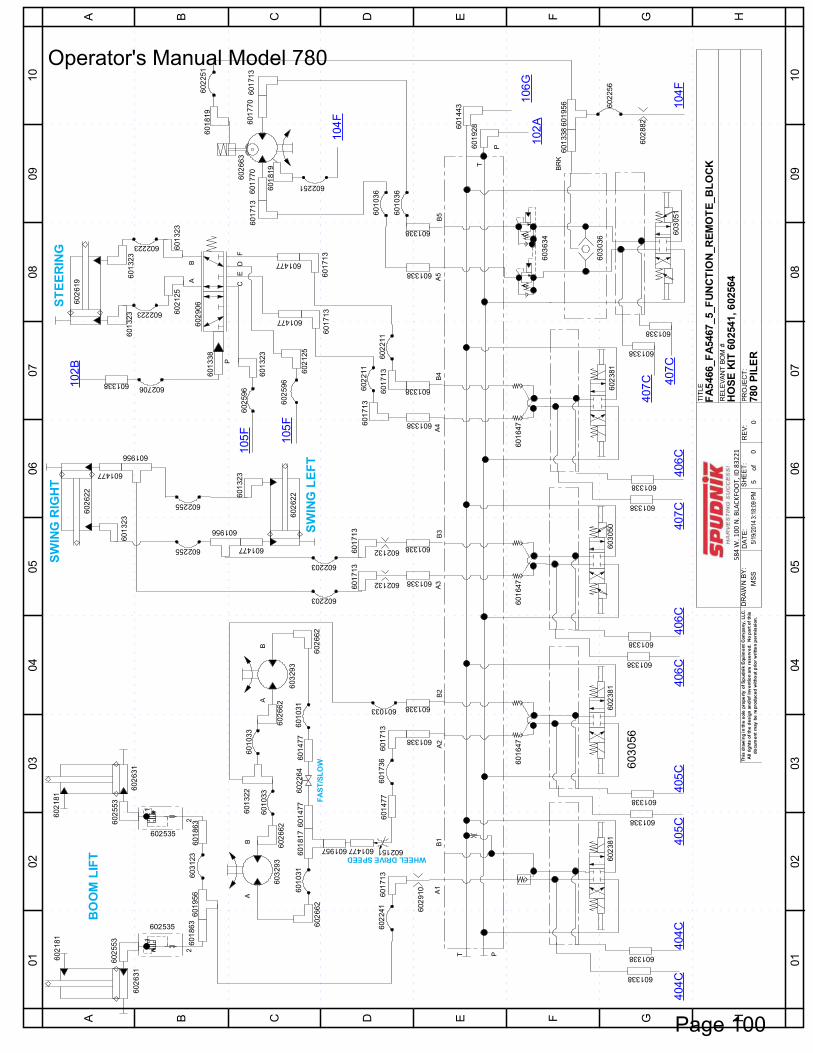
01 01
02 02
03 03
04 04
05 05
06 06
07 07
08 08
09 09
10 10
AA
BB
CC
DD
EE
FF
GG
HH
584
W. 1
00 N
. BLA
CKFO
OT,
ID 8
3221
DR
AW
N B
Y:
DA
TE
:S
HE
ET
:R
EV
:
TIT
LE
RE
LE
VA
NT
BO
M #
PR
OJE
CT
:M
SS
5/19
/201
4 3:
18:0
9 PM
5o
f0
0
FA
546
6_F
A54
67_5
_FU
NC
TIO
N_R
EM
OT
E_
BL
OC
K
HO
SE
KIT
60
2541
, 602
564
780
PIL
ER
Th
is d
raw
ing
in
th
e s
ole
pro
pe
rty
of
Sp
ud
nik
Eq
uim
en
t C
om
pa
ny
, L
LC
.A
ll ri
gh
ts o
f th
e d
esi
gn
an
d/o
f in
ve
nti
on
are
re
se
rve
d.
No
par
t o
f th
isd
ocu
me
nt
may
be
re
pro
du
ce
d w
ith
ou
t p
rio
r w
ritt
en
pe
rmis
sio
n.
601
9286
014
43
102
A1
06G
601
338
601
956 6
022
56
602
882
104
F
601338
601338
601338
601338
601338
601338
601338
601338
602
910601
713
602
241
602
631
602
553
602
181
2
1
602535
601
863
601
956
603
123
BO
OM
LIF
T
601
713
601
736
601
477
602151601477601957
601
817
601
477
602
264
601
477
601
031
602
662
601
031
602
662
603
293
BA
602
662
601
033
601
322
601
033
603
293
BA
602
662 601033
WHEEL DRIVE SPEED
FA
ST
/SL
OW
602132
601
713
602132601
713
602203
602203
602
622
602
622
601
323
601
323
601477
601477
601956
601956
602255
602255
602
631
602
553
602
181
2
1
602535
601
863
SW
ING
RIG
HT
SW
ING
LE
FT
601
036
601
036
602
663
601
770
601
770
601
819
601
819
602251
601
713
601
713
104
F
602
251
601
323
602
125
602
596
602
596
105
F
105
F
601477
601477
601
338
602706601338102
B
601
713
601
713
601
713
601
713
602
211
602
211
601338
601338
407
C 407
C
601338
601338
406
C4
07C
601338
601338
406
C4
06C
601338
601338
405
C4
05C
601338
601338
404
C4
04C
BR
K
601
647
601
647
601
647
603
036
603
634
602
381
603
051
602
381
603
050
602
381
PT
A1
B1
B2
A2
B3
A3
B4
A4
B5
A5
P
T
603
056
P
602
906
B
F
A
EC
D
602
619
601
323
601
323
602223
602223 601
323
602
125
ST
EE
RIN
GOperator's Manual Model 780
Page 100
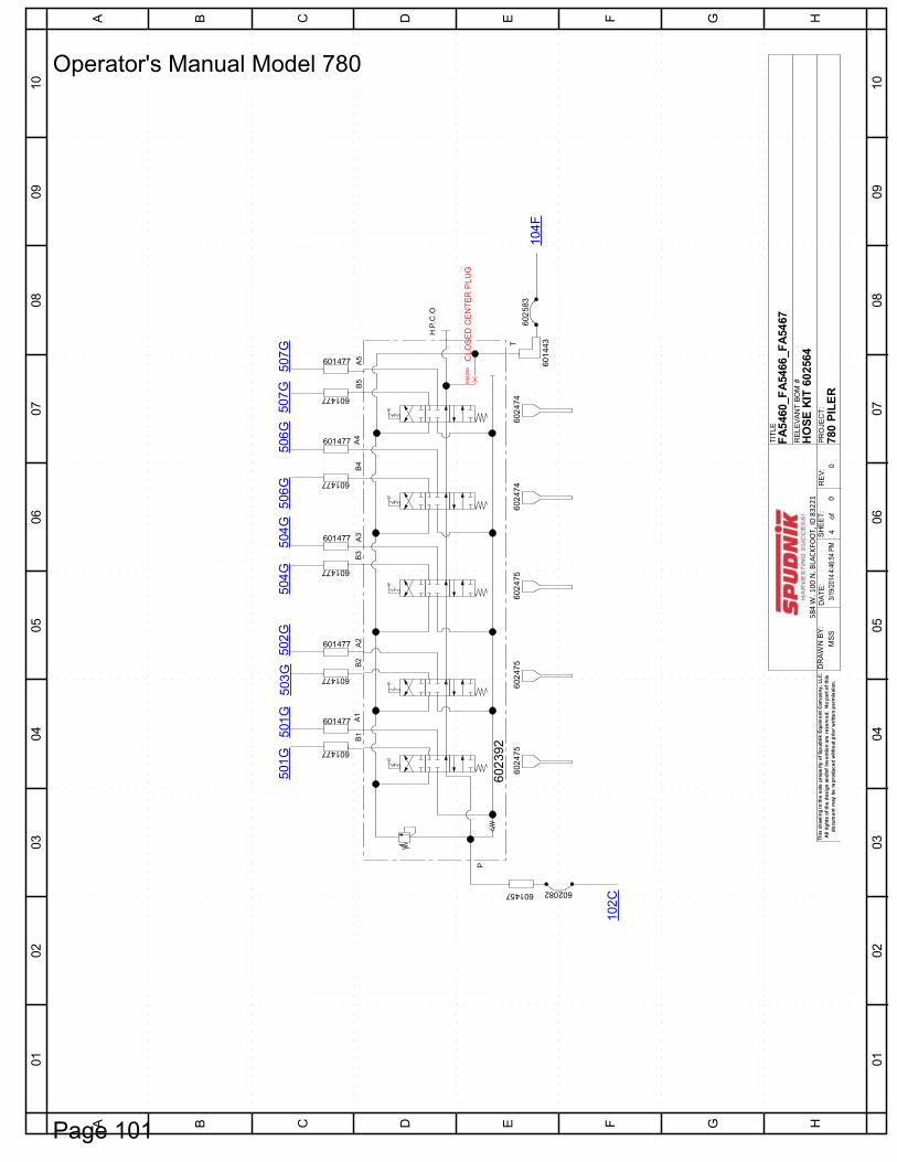
01 01
02 02
03 03
04 04
05 05
06 06
07 07
08 08
09 09
10 10
AA
BB
CC
DD
EE
FF
GG
HH
584
W. 1
00 N
. BLA
CKFO
OT,
ID 8
3221
DR
AW
N B
Y:
DA
TE
:S
HE
ET
:R
EV
:
TIT
LE
RE
LE
VA
NT
BO
M #
PR
OJE
CT
:M
SS
3/19
/201
4 4:
46:5
4 PM
4o
f0
0
FA
546
0_F
A54
66_F
A54
67
HO
SE
KIT
60
2564
780
PIL
ER
Th
is d
raw
ing
in
th
e s
ole
pro
pe
rty
of
Sp
ud
nik
Eq
uim
en
t C
om
pa
ny
, L
LC
.A
ll ri
gh
ts o
f th
e d
esi
gn
an
d/o
f in
ve
nti
on
are
re
se
rve
d.
No
par
t o
f th
isd
ocu
me
nt
may
be
re
pro
du
ce
d w
ith
ou
t p
rio
r w
ritt
en
pe
rmis
sio
n.
601457 602082
102
C
601
443
602
583
104
F
601477
601477
601477
601477
601477
601477
601477
601477
601477
601477
507
G5
07G
506
G5
06G
504
G5
04G
503
G5
02G
501
G5
01G
602
475
602
475
602
475
602
474
602
474
CL
OS
ED
CE
NT
ER
PL
UG
602
246
P
T
A4
B4
B5
A5
H.P
.C.O
B3
A3
B2
A2
B1
A1
602
392
Operator's Manual Model 780
Page 101
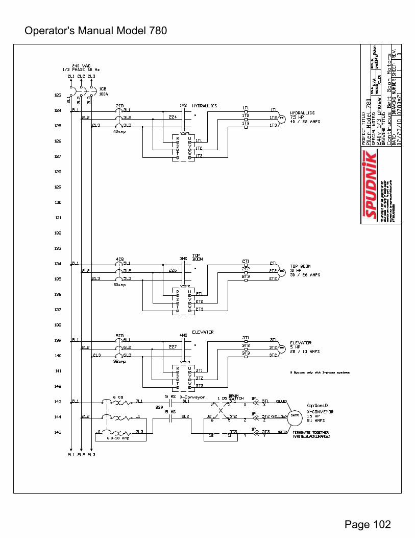
Operator's Manual Model 780
Page 102
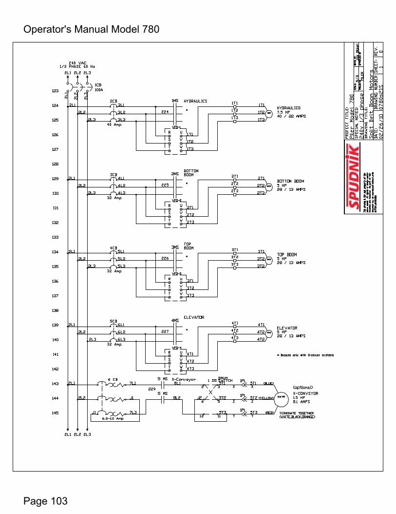
Operator's Manual Model 780
Page 103
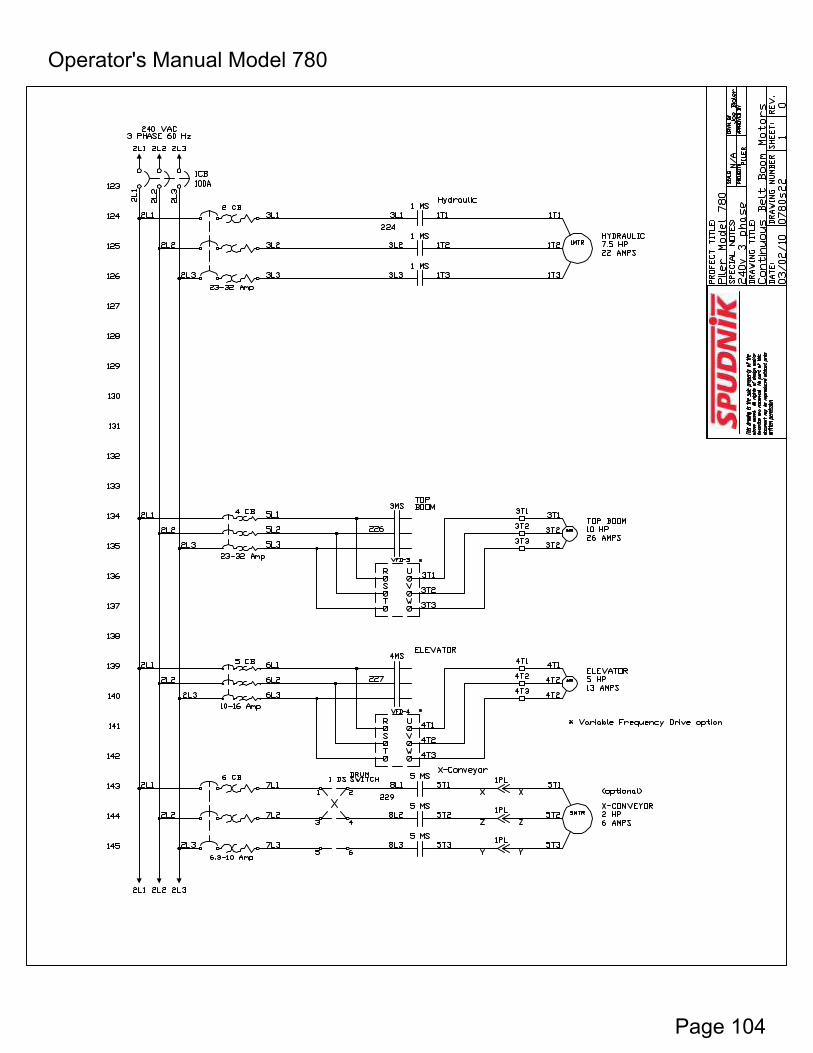
Operator's Manual Model 780
Page 104

Operator's Manual Model 780
Page 105

Operator's Manual Model 780
Page 106
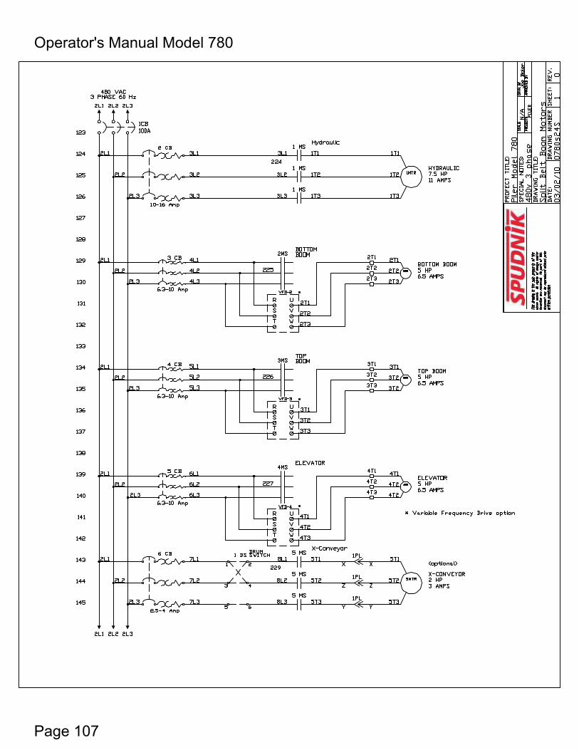
Operator's Manual Model 780
Page 107
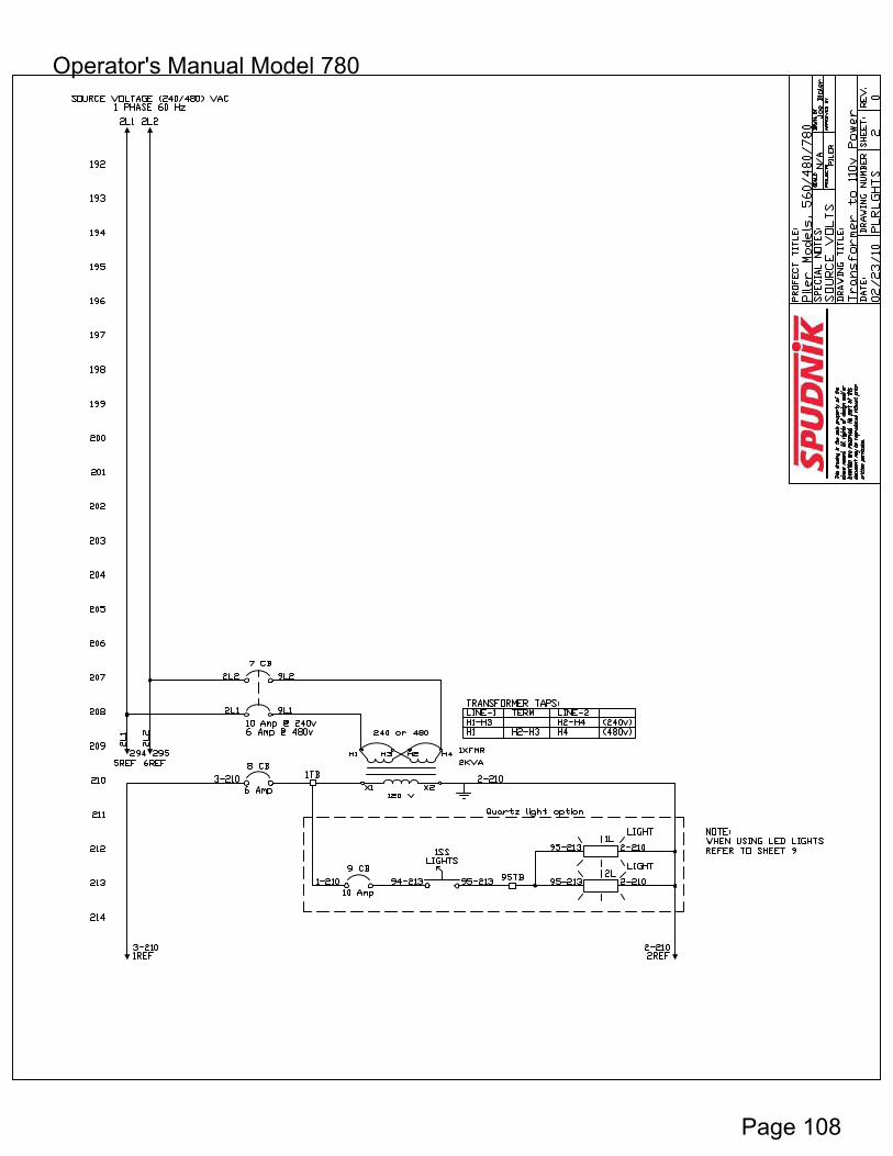
Operator's Manual Model 780
Page 108
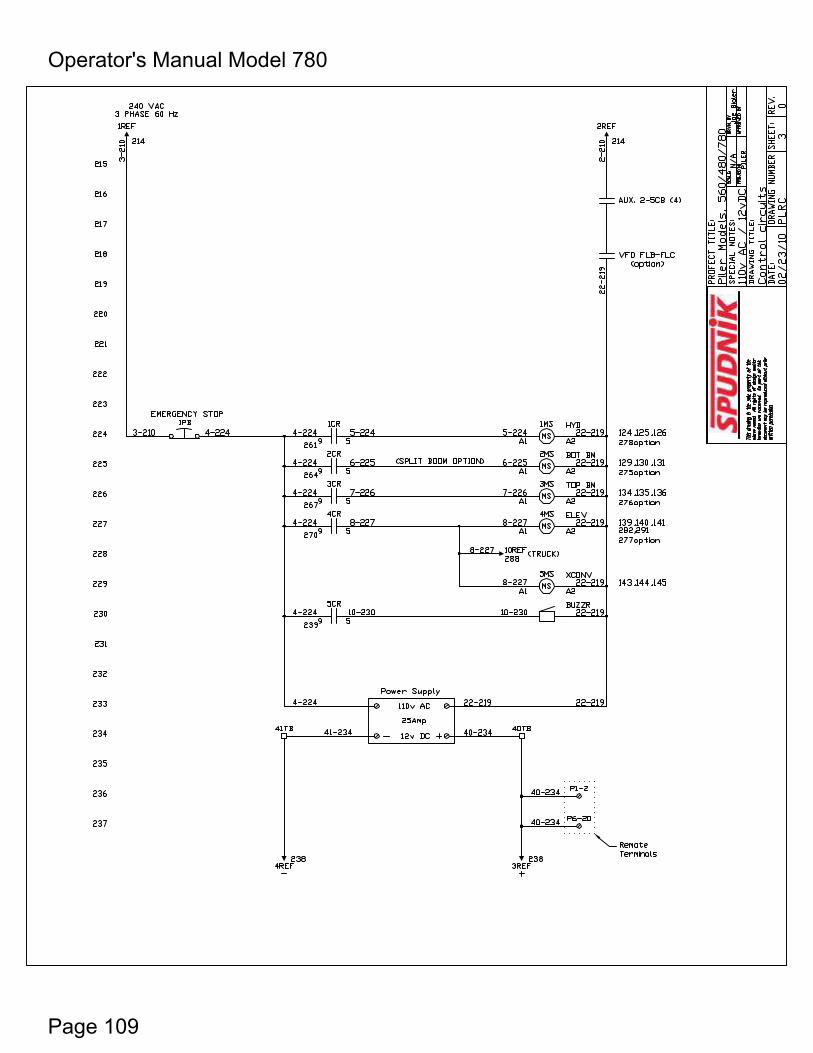
Operator's Manual Model 780
Page 109
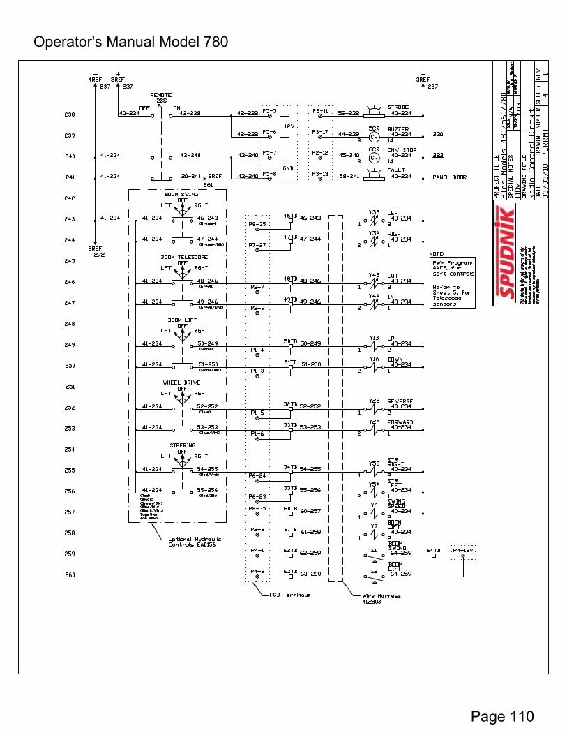
Operator's Manual Model 780
Page 110
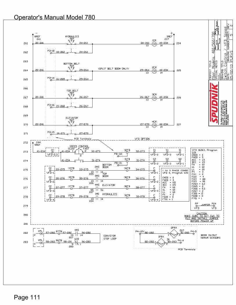
Operator's Manual Model 780
Page 111
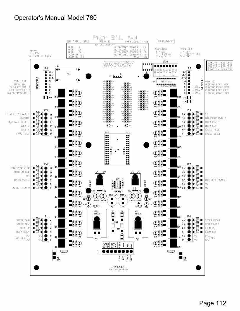
Operator's Manual Model 780
Page 112
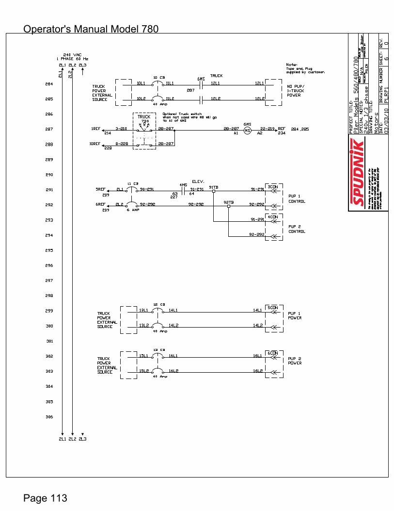
Operator's Manual Model 780
Page 113
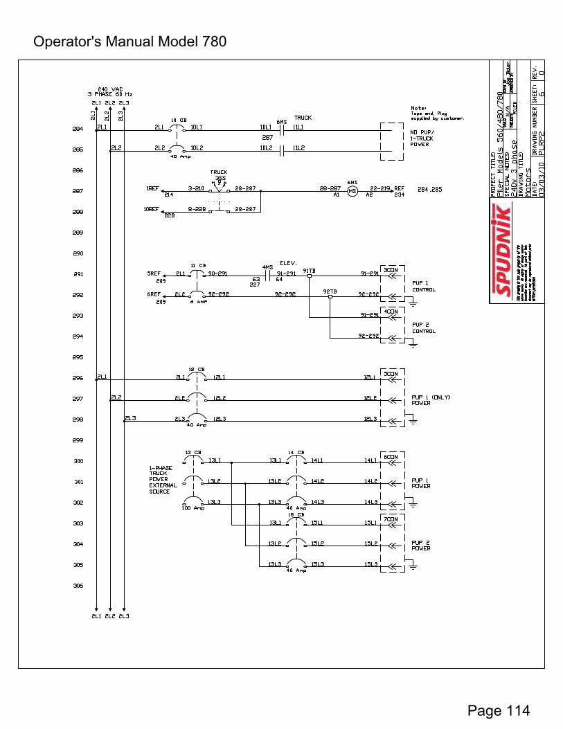
Operator's Manual Model 780
Page 114
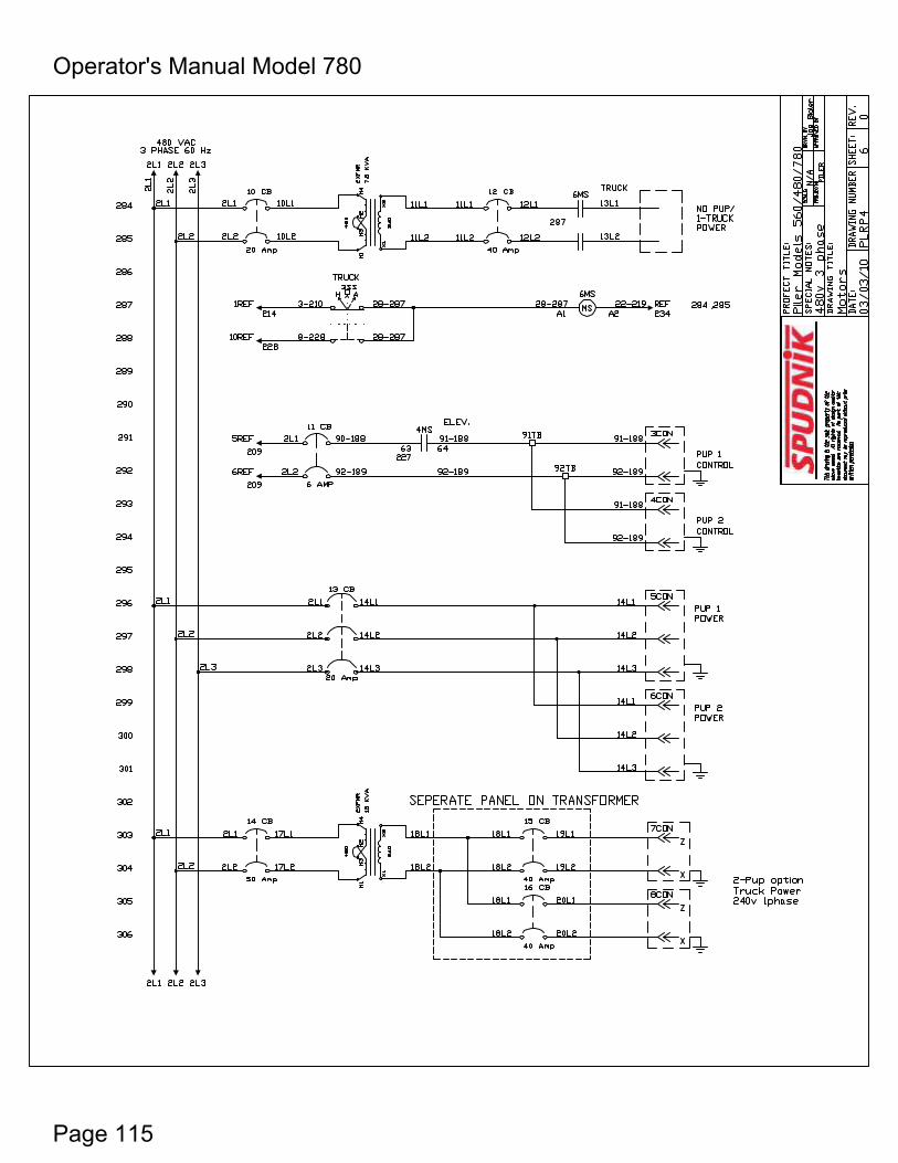
Operator's Manual Model 780
Page 115
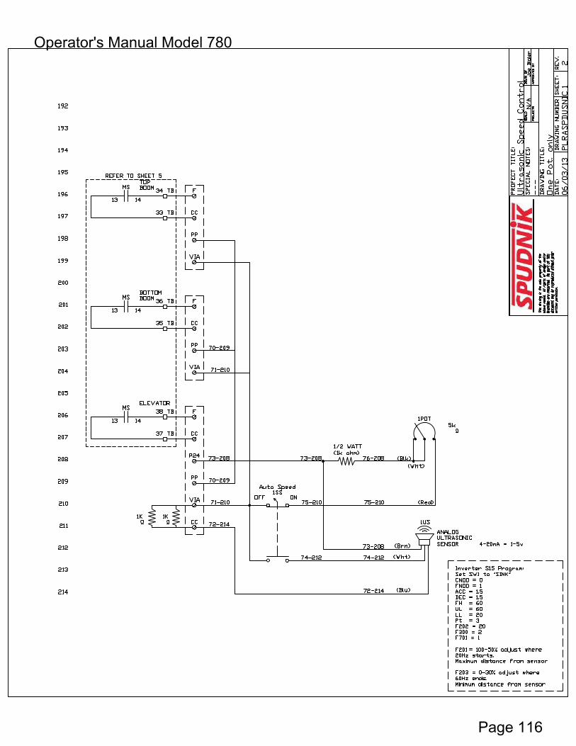
Operator's Manual Model 780
Page 116
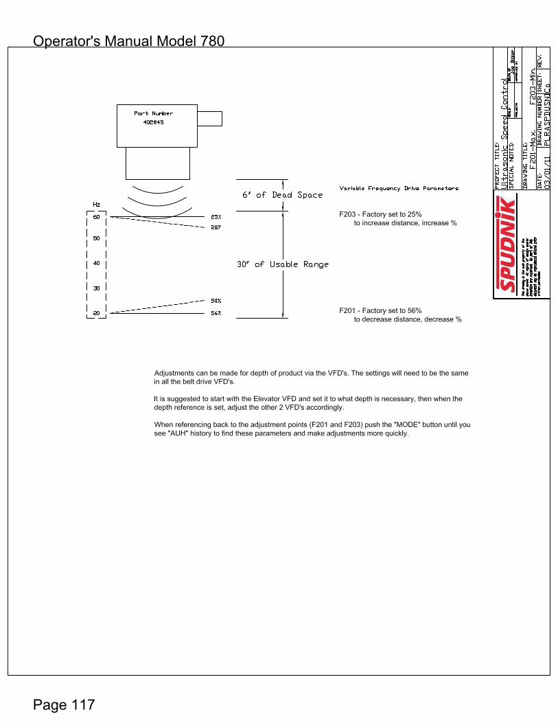
Operator's Manual Model 780
Page 117
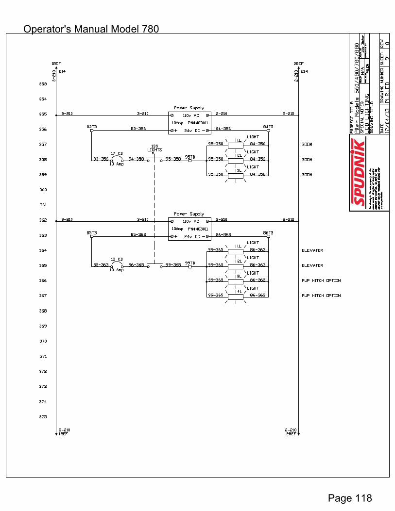
Operator's Manual Model 780
Page 118
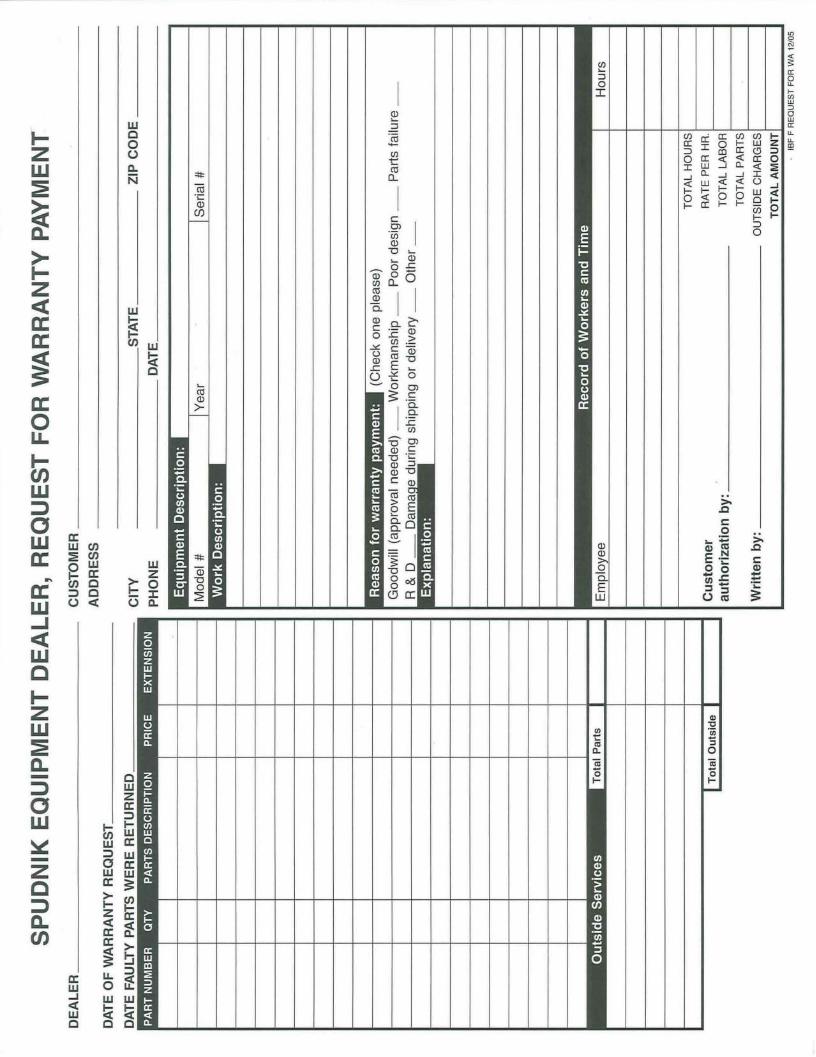


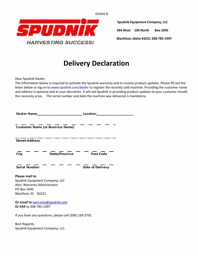
Exhibit B
Spudnik Equipment Company, LLC
584 West 100 North Box 1045
Blackfoot, Idaho 83221 208‐785‐1497
Delivery Declaration Dear Spudnik Dealer, The information below is required to activate the Spudnik warranty and to receive product updates. Please fill out the letter below or log on to www.spudnik.com/dealer to register the recently sold machine. Providing the customer name and address is optional and at your discretion. It will aid Spudnik in providing product updates to your customer should the necessity arise. The serial number and date the machine was delivered is mandatory.
Please mail to: Spudnik Equipment Company, LLC Attn: Warranty Administrator PO Box 1045 Blackfoot, ID 83221 Or email to [email protected] Or FAX to 208‐785‐1497 If you have any questions, please call (208) 239‐5791 Best Regards, Spudnik Equipment Company, LLC.