Embed Size (px)
Citation preview

IPL, MC-18, 2007-09, 542 20 11-33
MC-18
Spare Parts & Operator’s Manual Piezas de repuesto y Manual del operador
MC 18 9H MC 18 13H
542 20 11-33
HUSQVARNA CONSTRUCTION PRODUCTS

2
EVERY MACHINE IS THOROUGHLY TESTED BEFORE LEAVING THE FACTORY. EACH MACHINE IS SUPPLIED WITH A COPY OF THIS MANUAL. OPERATORS OF THIS EQUIPMENT MUST READ AND BE FAMILIAR WITH THE SAFETY WARNINGS. FAILURE TO OBEY WARNINGS MAY RESULT IN INJURY OR DEATH. FOLLOW INSTRUCTIONS STRICTLY TO ENSURE LONG SERVICE IN NORMAL OPERATION.
CONTENTSSymbol Defi nitions ................................................................................................................................ 3 - 5Decal Descriptions and Locations ........................................................................................................ 6Saw Confi gurations and Models / Power Source / Dimensions ........................................................... 7Safety Warnings - DO's & DO NOT's ................................................................................................... 8 - 9Reference Figures ................................................................................................................................ 10Pre-Operation Checklist / Maintenance Schedule ................................................................................ 11Instructions:
1. Features ................................................................................................................................ 122. Assembly ............................................................................................................................... 123. General Instructions .............................................................................................................. 124. Check Before Starting ........................................................................................................... 135. Fitting the Blade .................................................................................................................... 136. Starting the Power Source .................................................................................................... 137. Maneuver the Saw ................................................................................................................ 148. To Start Sawing ..................................................................................................................... 149. Stopping the Saw .................................................................................................................. 1410. Maintenance Instructions ...................................................................................................... 1511. Optional And Accessory (Field Installed) .............................................................................. 1512. Governor Speed .................................................................................................................... 1613. Repairs .................................................................................................................................. 1614. Service Parts ......................................................................................................................... 16
Parts List Diagrams:Diagram 1 - Frame & Axle .................................................................................................................... 18, 19Diagram 2 - Depth Control (Screw Feed) ............................................................................................. 20, 21Diagram 3 - Pointer & Belt Guard ......................................................................................................... 22, 23Diagram 4 - Guards & Water Distribution ............................................................................................. 24, 25Diagram 5 - Blade Guard...................................................................................................................... 26, 27Diagram 6 - Engine & Bladeshaft ......................................................................................................... 28, 29Diagram 7 - Kit, Water Tank (174957) .................................................................................................. 30

3
Symbol Defi nitions Defi nición De Simbolos
• Please Read The Instructions For Use Prior To Operating The Machine For The First Time.• Antes De La Puesta En Marcha, Lea Detenidamente Las Instrucciones Y Familiaricese Con La Máquina.
• Mandatory• Obligatorio
• Indication• Indicación
• Prohibition• Prohibición
• Warning Triangle• Triángwulo De Advertencia
• Wear Eye Protection• Usar Gafas De Protección
• Wear Head Protection• Usar Casco De Protección
• Wear Breathing Protection• Usar Máscara De Protección
• The Use Of Ear Protection Is Mandatory• Es Obligatorio El Uso De Protección Auditiva
• Wear a Hard Hat• Usar Casco Duro
• Wear Safety Shoes• Usar Zapatos De Seguridad
• Wear Appropriate Clothing• Usar Ropa Adecuada
• Remove The Blade Prior To Hoisting, Loading, Unloading And Transporting The Machine On Jobsite• Desmontar El Disco Antes De Desplazar, Cargar, Descargar O Transportar La Máquina En La Obra
• Motor Off• Parar El Motor
• Use In Well Ventilated Area• Usar En Una Área Bien Ventilada

4
• Do Not Use In Flammable Areas• No Usar In Áreas Infl amables
• Machinery Hazard, Keep Hands And Feet Clear• Máquina Peligrosa - Mantenga Manos Y Pies Alejados De La Máquina
• Danger, Poison Exhaust Gas• Peligro, Gas De Escape Venenoso
• No Non-working Personnel In Area• Prohibido Para Personas Ajenas A La Obra
• No Smoking• No Fumar
• Do Not Operate Without All Guards In Place• No Operar Sin Todas Las Protecciones In Su Sitio
• Always Keep the Blade Guards In Place• Mantenga Siempre Las Protecciones De La Hoja En Su Sitio
• Water Supply On• Suministro De Agua Desconectado
• Water Supply Off• Suministro De Agua Des Conectado
• Keep Work Area Clean/Well Lit, Remove All Safety Hazards• Mantenga Limpio El Sitio De Trabajo/Bien Iluminado, Elimine Todos Los Riesgos De Seguridad
• Dangerously High Noise Level• Nivel De Ruido Elevadamente Peligroso
• Pay Extreme Attention To The Care And Protection Of The Machine Before Starting Up• Ponga Extrema Atención Al Cuidado Y Preparación De La Máquina Antes De Ponerla En Marcha
• Remove Tools From Area And Machine• Elimine Las Herramientas Del Área Y De La Máquina
• Oil Required• Necesita Aceita
• Dipstick, Maintain Proper Oil Level• Varilla De Control, Mantenga El Nivel De Aceite Correcto
• Lubrication Point• Punto De Lubrication
• Unleaded Fuel Only• Combustible Sin Piomo Solamente

5
• Repairs Are To Be Done By An Authorized Dealer Only• Las Reparaciones Deben Ser Efectuadas Únicamente Por Un Distribuidor Autorizado
• Diamond Blade• Sierra Diamantada
• Blade Diameter• Diámetro De La Hoja
• Pulley Diameter• Diámetro De La Correa
• Number of Revolutions Per Minute, Rotational Speed• N° De Revoluciones Por Minuto, Velocidad De Rotación
• Blade Flange Diameter• Diámetro De La Brida De La Hoja
• Machine Mass (lbs)• Masa De La Máquina (lbs)
• Engine• Motor
• Engine Speed Revolutions/Minute• Velocidad Del Motor En Revoluciones Por Minuto (RPM)
• Engine Start• Arranque Del Motor
WARNINGHEARING HAZARD
DURING NORMAL USE OF THIS MACHINE, OPERATOR MAY BE EXPOSED TO A NOISE LEVEL EQUAL OR SUPERIOR TO 85 dB (A)
ATENCIONRIESGO DE DAÑO AUDITIVO
EN CONDICIONES NORMALES DE UTILIZACIÓN, EL OPERADOR DE ESTA MÁQUINA PUEDE ESTAR EXPUESTO A UN NIVEL DE RUIDO IGUAL O SUPERIOR A 85 dB (A)
6
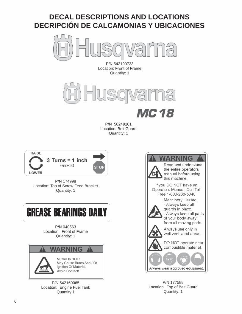
DECAL DESCRIPTIONS AND LOCATIONSDECRIPCIÓN DE CALCAMONIAS Y UBICACIONES
P/N 542190733Location: Front of Frame
Quantity: 1
P/N 50249101Location: Belt Guard
Quantity: 1
P/N 177588Location: Top of Belt Guard
Quantity: 1
P/N 040563Location: Front of Frame
Quantity: 1
P/N 542169065Location: Engine Fuel Tank
Quantity 1
P/N 174998Location: Top of Screw Feed Bracket
Quantity: 1

7
Power SourceMC 18 Model MC 18 9H MC 18 13HHorsepower 9 HP 13 HP
Screw Feed Model
Max. Blade Cap. in. (mm) 18 (450)Max. Depth of CutBlade Shaft RPM 2,600 2600Weight Crated - lb. (Kg) 209 (95) 222 (101)Uncrated - lb. (Kg) 182 (83) 195 (88)Arbor Size Blade FlangeBlade DriveBlade ControlBlade CoolantAxle FrontWheels FrontRearChassis
Engine/Motor HondaGas Engine
HondaGas Engine
Specifications GX270 GX390Max. Horsepower 9 HP 13 HPDisplacement cu. in. (cc) 16.5 (270) 23.7 (389)Bore - in. (mm) 3.0 (76) 3.5 (88)Stroke - in. (mm) 2.3 (58) 2.5 (64)Cylinders/Stroke 1/4 1/4Fuel Capacity - gal. (l) 1.59 (6.0) 1.72 (6.5)Oil Capacity - pt.(l) 2.3 (1.1) 2.3 (1.1)Air Filter Dry type
dual elementw/pre cleaner
Dry typedual elementw/pre cleaner
Starter Recoil RecoilEngine Coolant Air AirOil Sentry Standard Standard
InchesA - Height (Max.) - In. (mm) 47-1/2 (1207)B - Saw Length, Pointer Up 45-1/2 (1156)C - Max. Saw Length, Pointer Down & Handles Out 64-1/4 (1632)E - Pointer Extension 18-3/4 (476)F - Frame Width 16 (406)G - Frame Length 22-1/2 (572)H - Saw Width 22 (559)I - Front Axle Length 10-1/4 (260)J - Rear Wheel Track 19-1/2 (495)K - Blade to Wall 2-3/8 (61)L - Wheel Base Length 15 (381)
MC 18 Specifications
POWER SOURCE:
SAW DIMENSIONS: Inches (mm)Crated Dimensions: L-35" x H-30-1/2" x W-22" (889 x 775 x 559mm)
ALL SAWS FEATURE:
One piece reinforced box base
Gas
4-5/8"-6-5/8" (117.5-168.3mm)
Removable dual water spray tubes; water supply connector located on left side of saw; control
Specifications are subject to change without notice.
3/4" (19 mm) diameter; raises and lowers cutting head
8" x 2" x 5/8" (203 x 51 x 15.9mm); ball bearings; semi-pneumatic tires
1" (25.4mm)4-1/2" dia. with drive pin3 V-belts (9 & 13 HP engine)Spring assisted screw feed
Metric (mm)
5" x 1-1/2" x 3/4" (102 x 38 x 19mm); solid rubber tires, cast iron hub, roller bearings, lube fitting

8
DO
WARNING: FAILURE TO COMPLY WITH THESE WARNINGS AND OPERATING INSTRUCTIONS COULD RESULT IN DEATH OR SERIOUS BODILY INJURY.
SAFETY FIRST!
WARNINGSDO’s and DO NOT’s
DO read this entire operator’s manual before operating this machine. Understand all warnings, instructions, and controls. DO keep all guards in place and in good condition. DO wear safety approved hearing, eye, head and respiratory protection. DO read and understand all warnings and instructions on the machine. DO read and understand the symbol defi nitions contained in this manual. DO keep all parts of your body away from the blade and all other moving parts. DO know how to stop the machine quickly in case of emergency. DO turn the “ON/OFF” switch to the “OFF” position prior to connecting the electric powered model to the power source. DO inspect the blade, fl anges and shafts for damage before installing the blade. DO use the blade fl ange size shown for each blade size.DO use only steel center diamond blades manufactured for use on concrete saws. DO use only reinforced abrasive blades or steel center diamond blades manufactured for use on concrete saws. DO use only the blade fl anges supplied with the saw. Never use damaged or worn blade fl anges. DO use only blades marked with a maximum operating speed greater than the blade shaft speed. Verify speed by checking blade shaft
rpm and pulley diameters. DO verify saw drive confi guration by checking blade shaft RPM, pulley diameters, and blade fl ange diameter. DO read all safety materials and instructions that accompany any blade used with this machine. DO inspect each blade carefully before using it. If there are any signs of damage or unusual wear, DO NOT USE THE BLADE. DO mount the blade solidly and fi rmly. Wrench tighten the arbor nut. DO make sure the blade and fl anges are clean and free of dirt and debris before mounting the blade on the saw. DO use the correct blade for the type of work being done. Check with blade manufacturer if you do not know if blade is correct. DO use caution and follow the instructions when loading and unloading the machine. DO operate this machine only in well ventilated areas. DO instruct bystanders on where to stand while the machine is in operation. DO establish a training program for all operators of this machine. DO clear the work area of unnecessary people. Never allow anyone to stand in front of or behind the blade while the engine is running. DO make sure the blade is not contacting anything before starting the engine. DO use caution when lifting and transporting this machine. DO always tie down the machine when transporting. DO use caution and follow instructions when setting up or transporting the machine. DO have all service performed by competent service personnel. DO make sure electric powered machines are plugged into a properly grounded circuit. DO make sure power cords are the proper size and in good condition.DO verify the blade arbor hole matches the machine spindle before mounting the bladeDO always check for buried electrical cables before sawing. If unsure, contact the local utilities. DO clean the machine after each day’s use. DO follow all electrical codes in your area.DO consider work area environment. Don’t expose power tools to rain. Don’t use power tools in wet locations.DO use caution to guard against electric shock. Prevent body contact with grounded surfaces (i.e., pipes, radiators, ranges, refrigerators). DO use correct voltage and proper extension cords. Never carry tool by cord or yank it to disconnect it from receptacle. Keep cord
away from heat, oil and sharp edges.DO always transport the machine with the motor stopped.DO keep the handles dry, clean and free of oil and dirt. DO disconnect tools from power source when not in use, before servicing and when changing accessories. DO carefully maintain and clean for better and safer performance. Follow instructions for changing accessories. Inspect tool cords peri-
odically and, if damaged, have repaired by authorized service facility. DO always give a copy of this manual to the equipment user. If you need extra copies, call TOLL FREE 1-800-288-5040.

9
SAFETY FIRST!
WARNINGSDO’s and DO NOT’s
WARNING: FAILURE TO COMPLY WITH THESE WARNINGS AND OPERATING INSTRUCTIONS COULD RESULT IN DEATH OR SERIOUS BODILY INJURY.
DO NOT DO NOT operate this machine unless you have read and understood this operator’s manual.DO NOT operate this machine without the blade guard, or other protective guards in place.DO NOT stand behind or in front of the blade path while the engine/motor is running.DO NOT leave this machine unattended while the engine/motor is running.DO NOT work on this machine while the engine/motor is running.DO NOT operate this machine when you are tired or fatigued.DO NOT use a wet blade without adequate water supply to the blade.DO NOT exceed maximum blade speed shown for each blade size. Excessive speed could result in blade breakage.DO NOT operate the machine if you are uncertain of how to run the machine.DO NOT use damaged equipment or blades.DO NOT touch or try to stop a moving blade with your hand.DO NOT cock, jam, wedge or twist the blade in a cut.DO NOT transport a cutting machine with the blade mounted on the machine.DO NOT use a blade that has been dropped or damaged.DO NOT use carbide tipped blades.DO NOT touch a dry cutting diamond blade immediately after use. These blades require several minutes to cool after each cut.DO NOT use damaged or worn blade fl anges.DO NOT allow other persons to be near the machine when starting, refueling, or when the machine is in operation.DO NOT operate this machine in an enclosed area unless it is properly vented.DO NOT operate this machine in the vicinity of anything that is fl ammable. Sparks could cause a fi re or an explosion.DO NOT allow blade exposure from the guard to be more than 180 degrees. DO NOT operate this machine with the belt guard or blade guard removed.DO NOT operate this machine unless you are specifi cally trained to do so.DO NOT use a blade that has been over heated. (Core has a bluish color.)DO NOT jam material into the blade.DO NOT grind on the side of the blade.DO NOT lay power cords in or near the water.DO NOT tow this machine behind a vehicle.DO NOT replace the motor with any motor that does not have a special grounding connection. DO NOT operate this machine while under the infl uence of drugs or alcohol.
*****************This saw was designed for certain applications only. DO NOT modify this saw or use for any application other than for which it was designed. If you have any questions relative to its application, DO NOT use the saw until you have written Diamant Boart, Inc. and we have advised you.
Husqvarna Constructuion Products N. A.17400 West 119th Street
Olathe, Kansas 66061USA
10
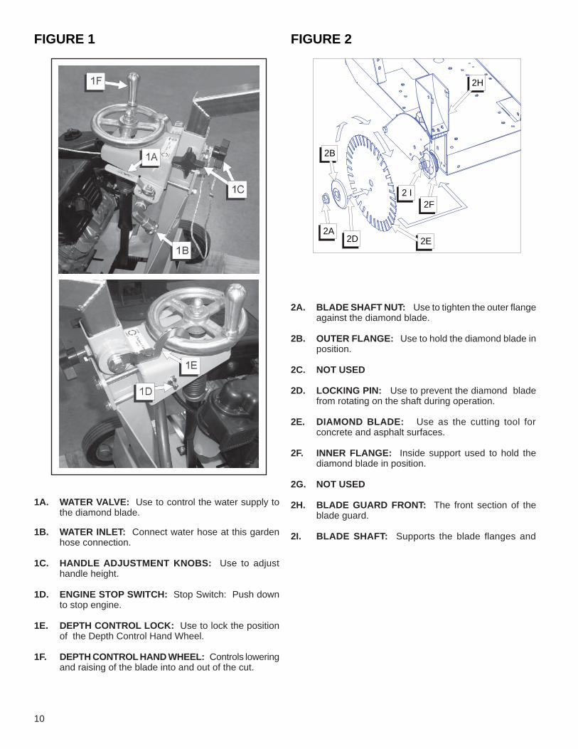
FIGURE 2
2A. BLADE SHAFT NUT: Use to tighten the outer fl ange against the diamond blade.
2B. OUTER FLANGE: Use to hold the diamond blade in
position. 2C. NOT USED 2D. LOCKING PIN: Use to prevent the diamond blade
from rotating on the shaft during operation. 2E. DIAMOND BLADE: Use as the cutting tool for
concrete and asphalt surfaces. 2F. INNER FLANGE: Inside support used to hold the
diamond blade in position. 2G. NOT USED
2H. BLADE GUARD FRONT: The front section of the blade guard.
2I. BLADE SHAFT: Supports the blade fl anges and
2D 2E
2H
2B
2 I2F
2A
FIGURE 1
1A. WATER VALVE: Use to control the water supply to the diamond blade.
1B. WATER INLET: Connect water hose at this garden
hose connection.
1C. HANDLE ADJUSTMENT KNOBS: Use to adjust handle height.
1D. ENGINE STOP SWITCH: Stop Switch: Push down to stop engine.
1E. DEPTH CONTROL LOCK: Use to lock the position of the Depth Control Hand Wheel.
1F. DEPTH CONTROL HAND WHEEL: Controls lowering and raising of the blade into and out of the cut.
11
PRE OPERATION CHECKLISTBefore leaving our factory, every machine is thoroughly tested. Follow our instructions strictly and your machine will give you long service in normal operating conditions.
Before starting up the machine, make sure you read this entire operations manual and are familiar with the operation of the machine.
WITH MACHINE COLD AND SETTING LEVEL:
1. Check engine oil. Fill to full mark on dip stick with 10W30 oil. DO NOT OVERFILL!! • Gas Models: Class MS, SD, SE or better.
1 - 2 HOUR OPERATION CHECK:
ALWAYS park machine on a level surface with the engine “OFF” and the engine switch set in the “OFF” position before performing any maintenance. Let the machine cool down!!
1. Tension the blade drive V-belts. DO NOT over tension!!
SCHEDULED MAINTENANCE QUICK REFERENCE:
Before performing any maintenance, ALWAYS park the machine on a level surface with the engine “OFF” and the engine switch set in the “OFF” position.
SERVICE DAILY: 1. Check engine oil level.2. Check blade guard for damage.3. Check engine air fi lter, replace if dirty.4. Lubricate bladeshaft bearings. 5. Lubricate front wheel bearings.6. Check blade drive V-belt tension. DO NOT over
tension!!! Change in sets only!
SERVICE EVERY 50 HOURS: 1. Replace engine oil and fi lter.2. Clean engine/motor air fi ns.3. Lubricate depth control adjustment screw. (Screw
Feed version only.)4. Check wheels for wear or damage.
NOTE: See engine manual for specifi c engine maintenance for your specifi c model.

12
• The Handle must be attached. Place Handle in position and securely tighten Knobs.
• Check the engine oil level. Service before using. Refer to the engine operation manual for detailed information.
These signs will giveadvice for your safety
Before leaving our factory every machine isthoroughly tested.
Follow our instructions strictly and your ma-chine will give you long service in normal operating
MANDATORYINDICATIONINFORMATIONINSTRUCTION
WARNING PROHIBITION
Use: Wet sawing of old and new concrete and asphalt.Tools: Diamond blades — water cooled, Ø: 10", 12", 14", 18" and 20" with Arbor Ø - 1"
(For information, contact your Husqvarna supplier)
Before starting up the machine, make sure you read this entire manual and are fami l i a r w i th the opera t ion o f th is machine.
The working area must be completely clear, well lit and all safety hazards removed.
The operator must wear p r o t e c t i v e c l o t h i n g appropriate to the work he is doing.
Any persons not involved in the work, should leave the area.
Use only blades marked with a maximum operating speed greater than the bladeshaft speed.
Remove the Blade (2E) before transport.
WARNING: DO NOT operate without the proper blade guard over the Blade! (2E)
WARNING: DO NOT operate the saw with the front of the Blade Guard (2H) raised!
WARNING: Blade exposure CANNOT exceed 180 degrees when operating!
• The Front Pointer must be checked for alignment with the Blade (2E). It must be in line with the Blade (2E) mounted on the Blade Shaft (2I).
• For WET SAWING, be sure the water jets in the blade guard water tubes are open and that each side of the Blade (2E) has an adequate supply of water. Test the water supply for pressure and quantity (fl ow) before starting to saw.
WATER FLOW from 2-1/2 to 5 gallons of water per minute MUST fl ow over the blade to properly cool it and to get maximum blade life. DO NOT use conventional (wet) diamond blades without water!
• Saw only as deep as the specifications and job conditions require. Sawing excessively deep is wasteful–avoid it! Step cut in increments of 2 inches (50 mm) for best results.
• Saw in a straight line. Mark the cutting line clearly so the saw operator can follow the line without diffi culty. The saw should NOT be twisted from side to side try-ing to force the blade back on the line.
CUTTING DEPTHS MAXIMUM MC18BLADE SIZE BLADE DEPTH MAXIMUM DEPTH (To Collar) (To Depth Stop)10" (250mm) 2 3/4" (68mm) 2 1/2" (62mm)12" (300mm) 3-3/4" (93mm) 3-1/2" (87mm)14" (350mm) 4-3/4" (118mm) 4-1/2" (112mm)18" (450mm) 6-3/4" (164mm) 6-1/2" (158mm)
1 Features
3 General Instructions
2 Assembly

13
Always pay extreme care and attention to the preparation of the machine before starting.
Remove all wrenches and tools from the fl oor and the machine.
Always keep blade guard and transmission guard in place.
(See Fig. 1 and 2)
Always set the Engine Switch (1D) to the "OFF" position before mounting the Blade (2E).
• Set the Engine Switch (1D) to the "OFF" position.• Raise the machine to a high position [by cranking the
Raise/Lower Hand Wheel].• Raise the front half of the Blade Guard (2H).• Unscrew the Blade Shaft Nut (2A). Remove Outer
Flange (2B).• Fit Diamond Blade (2E) on the Blade Shaft Arbor.• Install Outer Flange (2B) into the Blade Shaft (2I)
making sure that the Locking Pin (2D) passes through the Diamond Blade (2E) and into the Inner Flange (2F).
Note the direction of rotation of the blade. The direction of rotation is shown by an arrow on the Diamond Blade (2E). Make sure that the contact surfaces on the Diamond Blade (2E), Inner & Outer Flanges (2B & 2F) and Blade Arbor are clean.
• Rotate Outer Flange (2B) and the Blade (2E) in the opposite direction of blade rotation to remove back-lash.
• Install and tighten Blade Flange Nut using the Blade Shaft Wrench [50 lb.-ft. (68 N-m)] while fi rmly holding the Diamond Blade (2E).
• Lower front half of Blade Guard (2H).
The Blade Shaft Nut (2A) on the Right Hand side has Left Hand threads.
On Gasoline Engine Models:1. Refer to the engine operating manual for proper engine
operation.
2. Fill the engine fuel tank and check the engine oil level. Refer to the engine manual for detailed information.
3. Start the engine. Refer to the engine manual for detailed information.
4. Let the engine warm up at half throttle. All sawing is done at full throttle. The governor is factory set for the correct engine speed. Do not change the Governor setting – it is factory set for the correct speed.
WARNING: To STOP ENGINE, PUSH the Engine Stop Switch DOWN, located on the handle support of the saw. [Wait for all engine movement to stop.]
Take into account the working conditions from the health and safety point of view.
FUEL: Check the engine maintenance manual.* Gas Models: Unleaded gasoline is recommended.
• Check that the engine oil level is correct. Because the engine often operates at an angle, check the oil level (with engine horizontal) frequently to ensure that the oil level never falls below the lower mark on the dipstick. 10W30 oil is recommended.
4 Check Before Starting
5 Fitting The Blade
6 Starting The Power Source

14
• Screw Feed Version: Raise the blade out of the cut by pulling up on the
depth control lock and slowly turning the hand wheel clockwise. Raise the blade (2E) high enough out of the cut to clear the pavement when maneuvering the saw.
• Turn off the Water Valve (1A).
• Turn the Engine Throttle to the IDLE position.
• STOP the engine by turning the Engine Switch (1D) to the OFF position.
• Follow all of the instructions outlined above.
• Open the Water Valve (1A) FULL open. Check the water to verify full fl ow, then adjust for proper amount of water on the blade BEFORE you lower the Blade.
Test for adequate water supply [2-1/2 to 5 gal/min (10 to 20 lit./min)]. Low water fl ow will cause damage to diamond blades.
If water supply is interrupted, stop cutting immediately.
Screw Feed Version:• Lower the blade into the cut by pulling up on the Depth
Control Lock (1E) and slowly turning the Hand Wheel COUNTER-CLOCKWISE. When the desired depth of cut is reached, push Depth Control Lock down to lock it in the hand wheel.
• During cutting, DO NOT exert excessive side pressure on the Handle Bars to attempt to “STEER” the saw. Use only enough pressure to follow the previously marked line.
• If the saw should stall for any reason, raise the blade completely out of the cut before starting your power source again!
• When lowering the Blade (2E) into a partially made cut, the blade must be perfectly aligned within the cut before starting to saw again. DO NOT FORCE the Blade (2E) into the material by lowering the Blade too fast, or by propelling the saw too fast.
• Set the handle bar height to a comfortable position.
• Raise the Blade (2E) as high as possible so that the Blade (2E) will not strike pavement when
7 To Maneuver the Saw
8 To Start Sawing
9 Stopping the Saw

15
SPECIAL OUTER FLANGE ASSY 1/2" (12.7mm)WIDE CUT (P/N 167963)• A Special Outer Flange Assembly is available as a
fi eld installed accessory. It enables the MC 18 to cut7/16" - 1/2" (11-12.7mm) wide.
WARNING: This special outer fl ange assembly is for use with blade width stacks of 7/16" - 1/2" (11mm-12.7mm) only! If blade width stacks of less than 7/16" (11mm) are required, use the standard outer fl ange assembly supplied with the MC 18. The Special Outer Flange Assembly can be identifi ed by the COUNTERBORE on the “Nut Side” of the fl ange. The Standard Outer Flange Assembly has NO COUNTERBORE.
WATER TANK KIT• A 6 gallon (23 liter) Water Tank Kit is available as a
Field installed accessory. Use only for dry cutting! The water tank is designed only to suppress airborne concrete dust.
WARNING: DO NOT use conventional (wet) diamond blades with the water tank as the water source, because there is not suffi cient wa-ter fl ow available to properly cool the blades!
TIE DOWN BRACKET KIT (P/N 167189)• A Tie Down Bracket Kit is available as a fi eld installed
accessory. The kit consists of two (2) tie down loops that are installed at the front of the frame. They are to be used only to SECURE the saw to a truck or trailer during transport.
WARNING: DO NOT use the t ie down brackets as a device for lifting the saw!
Before performing any maintenance, ALWAYS park the machine on a level surface with the Engine OFF and the Engine Switch in the "OFF" position.
After each use: CLEAN the machine.
LUBRICATION:
LUBRICATE DAILYFront Wheels and Blade Shaft Bearings
LUBRICATE EVERY 50 HOURSDepth Control Adjustment Screw (Screw Feed Version Only)
NOTE: When cutting dry, lubricate blade shaft bearings 2 or 3 times daily, the grease provides an added protective seal for the bearings. Use only a Premium Lithium 12 based Grease, conforming to NLG1 Grade #2 Consistency, without Molybdenum Disulfi de.
ENGINE OIL: Check daily. Keep the oil clean and at the proper level. 10W30 MS, SD, SE or better is generally recommended. Capacity levels indicated on page 10. DO NOT OVERFILL!! Change engine oil and oil fi lter every 50 HOURS of operation. Refer to the engine manual for detailed information.
CLEAN ENGINE AIR FILTER:Clean the air fi lter 2 or 3 times daily when dry cutting. Refer to the engine manual for detailed information.
ENGINE CARE:Refer to the engine manual for detailed information.
10 Maintenance 11 Optional and Accessory (Field Installed)
16
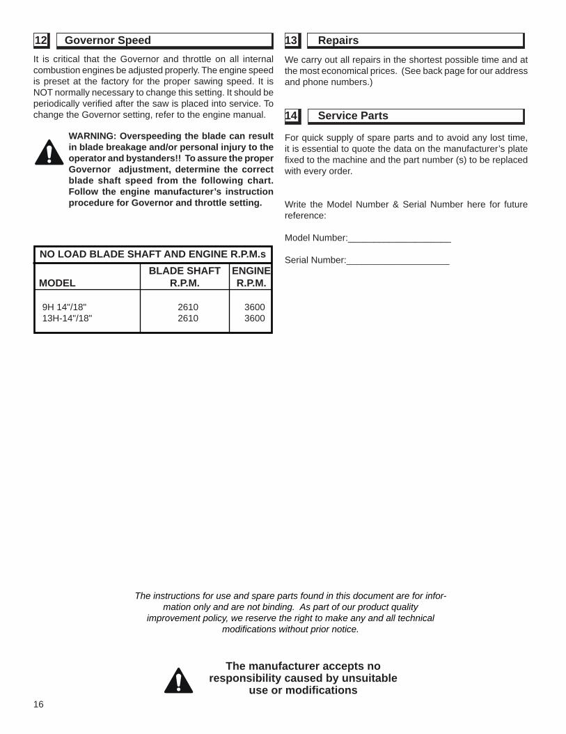
It is critical that the Governor and throttle on all internal combustion engines be adjusted properly. The engine speed is preset at the factory for the proper sawing speed. It is NOT normally necessary to change this setting. It should be periodically verifi ed after the saw is placed into service. To change the Governor setting, refer to the engine manual.
WARNING: Overspeeding the blade can result in blade breakage and/or personal injury to the operator and bystanders!! To assure the proper Governor adjustment, determine the correct blade shaft speed from the following chart. Follow the engine manufacturer’s instruction procedure for Governor and throttle setting.
The instructions for use and spare parts found in this document are for infor-mation only and are not binding. As part of our product quality
improvement policy, we reserve the right to make any and all technical modifi cations without prior notice.
We carry out all repairs in the shortest possible time and at the most economical prices. (See back page for our address and phone numbers.)
For quick supply of spare parts and to avoid any lost time, it is essential to quote the data on the manufacturer’s plate fi xed to the machine and the part number (s) to be replaced with every order.
Write the Model Number & Serial Number here for future reference:
Model Number:____________________
Serial Number:____________________
The manufacturer accepts no responsibility caused by unsuitable
use or modifi cations
NO LOAD BLADE SHAFT AND ENGINE R.P.M.s BLADE SHAFT ENGINE MODEL R.P.M. R.P.M.
9H 14"/18" 2610 3600 13H-14"/18" 2610 3600
12 Governor Speed 13 Repairs
14 Service Parts

17
NOTE:NOTA:

18
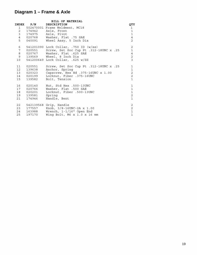
Diagram 1 – Frame & Axle
19
Diagram 1 – Frame & Axle BILL OF MATERIAL INDEX P/N DESCRIPTION QTY 1 502470001 Frame Weldment, MC18 1 2 174942 Axle, Front 1 3 174975 Axle, Pivot 1 4 020768 Washer, Flat .75 SAE 4 5 040091 Wheel Assy, 5 Inch Dia 2 6 541201090 Lock Collar, .750 ID (w/ss) 2 7 020551 Screw, Set Soc Cup Pt .312-18UNC x .25 1 8 020767 Washer, Flat .625 SAE 4 9 139569 Wheel, 8 Inch Dia 2 10 541200649 Lock Collar, .625 w/SS 3 11 020551 Screw, Set Soc Cup Pt .312-18UNC x .25 1 12 139638 Anchor, Spring 1 13 020323 Capscrew, Hex Hd .375-16UNC x 1.00 2 14 020199 Locknut, Fiber .375-16UNC 2 15 139582 Bolt, Tension 1 16 020140 Nut, Std Hex .500-13UNC 1 17 020766 Washer, Flat .500 SAE 1 18 020201 Locknut, Fiber .500-13UNC 1 19 139581 Spring 2 21 174946 Handle, Bent 1 22 542139568 Grip, Handle 2 23 177557 Knob, 3/8-16UNC-2A x 1.00 2 24 163988 Wrench, 1-1/16" Open End 1 25 197170 Wing Bolt, M6 x 1.0 x 16 mm 1
20
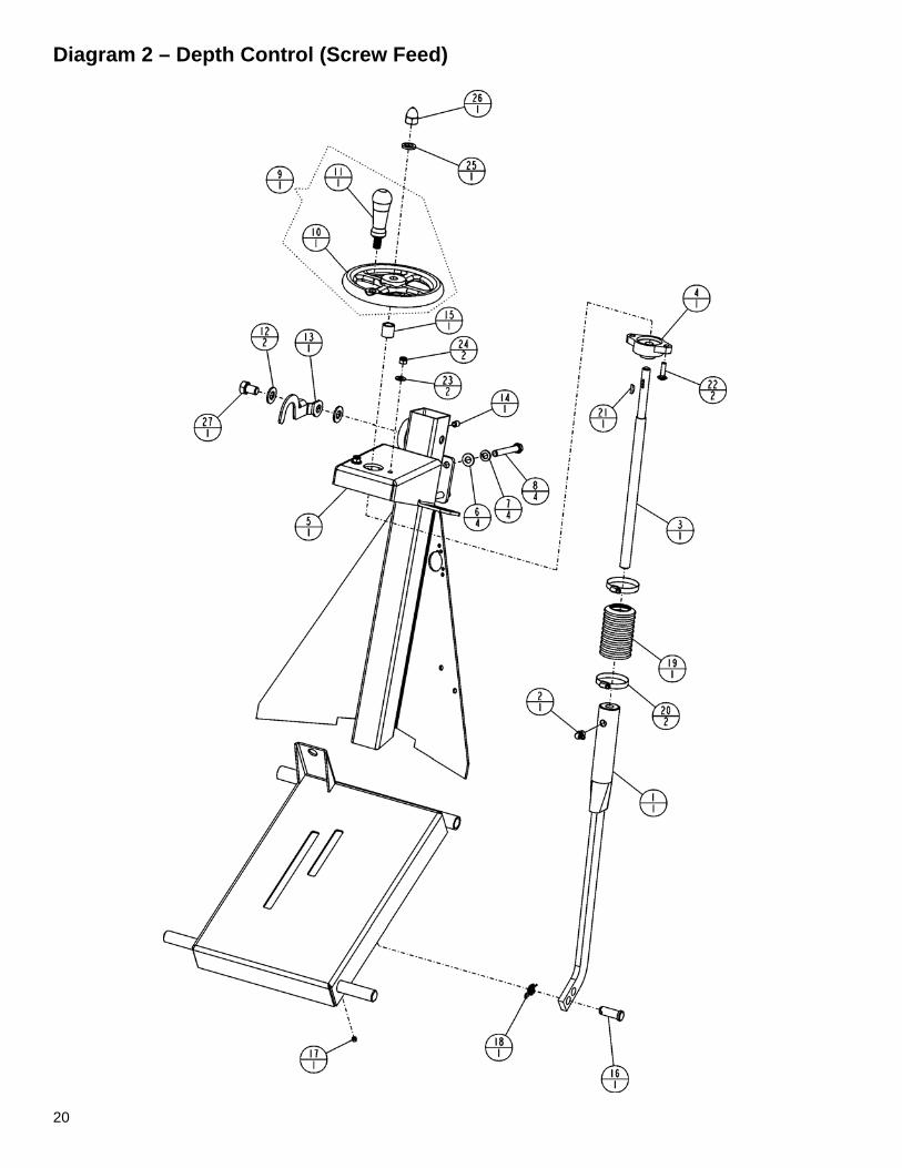
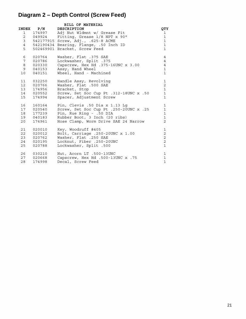
Diagram 2 – Depth Control (Screw Feed)
21
Diagram 2 – Depth Control (Screw Feed) BILL OF MATERIAL INDEX P/N DESCRIPTION QTY 1 174997 Adj Nut Wldmnt w/ Grease Fit 1 2 049924 Fitting, Grease 1/8 NPT x 90° 1 3 542177915 Screw, Adj., .625-8 ACME 1 4 542190434 Bearing, Flange, .50 Inch ID 1 5 502469901 Bracket, Screw Feed 1 6 020764 Washer, Flat .375 SAE 4 7 020786 Lockwasher, Split .375 4 8 020330 Capscrew, Hex Hd .375-16UNC x 3.00 4 9 040153 Assy, Hand Wheel 1 10 040151 Wheel, Hand - Machined 1 11 032250 Handle Assy, Revolving 1 12 020766 Washer, Flat .500 SAE 2 13 174956 Bracket, Stop 1 14 020552 Screw, Set Soc Cup Pt .312-18UNC x .50 1 15 174994 Spacer, Adjustment Screw 1 16 160164 Pin, Clevis .50 Dia x 1.13 Lg 1 17 020540 Screw, Set Soc Cup Pt .250-20UNC x .25 1 18 177239 Pin, Rue Ring - .50 DIA 1 19 040183 Rubber Boot, 3 Inch (20 ribs) 1 20 174961 Hose Clamp, Worm Drive SAE 24 Narrow 2 21 020010 Key, Woodruff #405 1 22 020012 Bolt, Carriage .250-20UNC x 1.00 2 23 020762 Washer, Flat .250 SAE 2 24 020195 Locknut, Fiber .250-20UNC 2 25 020788 Lockwasher, Split .500 1 26 030210 Nut, Acorn LT .500-13UNC 1 27 020668 Capscrew, Hex Hd .500-13UNC x .75 1 28 174998 Decal, Screw Feed 1

22
Diagram 3 – Pointer & Belt Guard
23
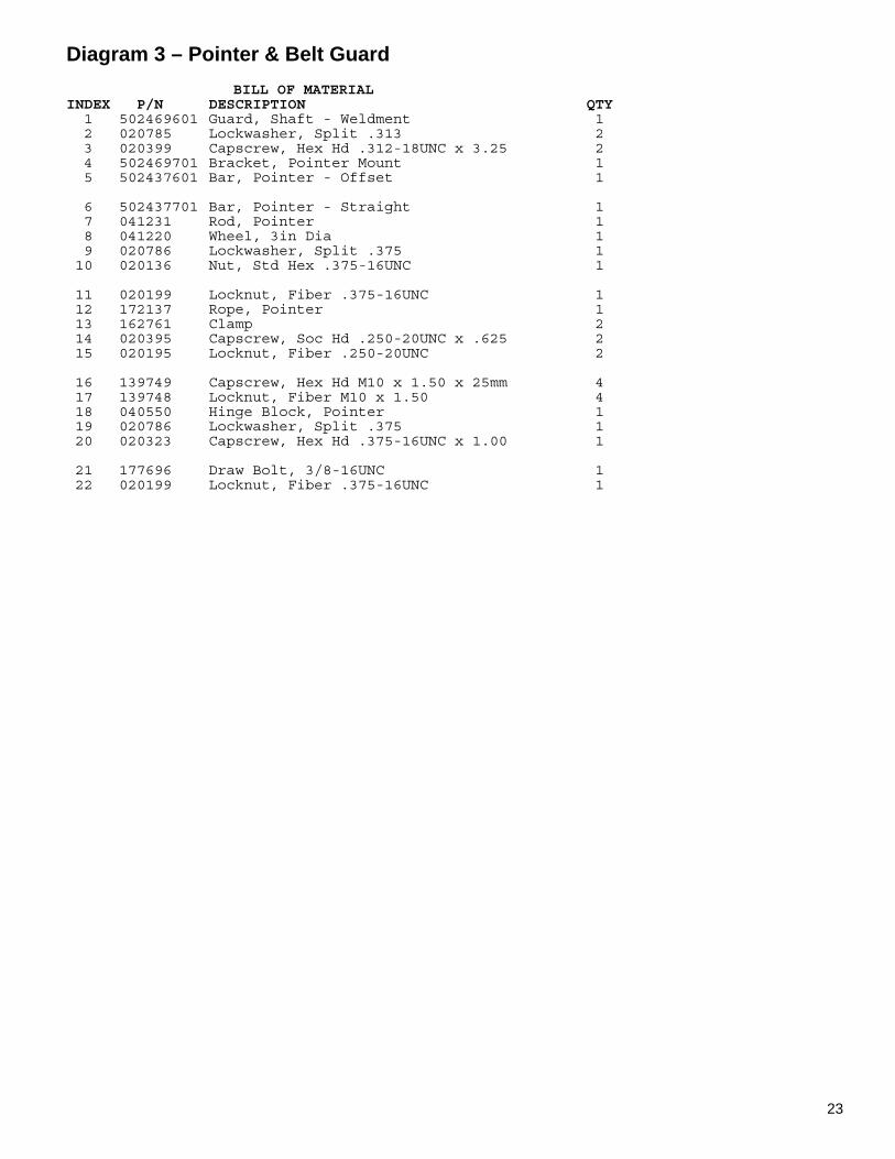
Diagram 3 – Pointer & Belt Guard BILL OF MATERIAL INDEX P/N DESCRIPTION QTY 1 502469601 Guard, Shaft - Weldment 1 2 020785 Lockwasher, Split .313 2 3 020399 Capscrew, Hex Hd .312-18UNC x 3.25 2 4 502469701 Bracket, Pointer Mount 1 5 502437601 Bar, Pointer - Offset 1 6 502437701 Bar, Pointer - Straight 1 7 041231 Rod, Pointer 1 8 041220 Wheel, 3in Dia 1 9 020786 Lockwasher, Split .375 1 10 020136 Nut, Std Hex .375-16UNC 1 11 020199 Locknut, Fiber .375-16UNC 1 12 172137 Rope, Pointer 1 13 162761 Clamp 2 14 020395 Capscrew, Soc Hd .250-20UNC x .625 2 15 020195 Locknut, Fiber .250-20UNC 2 16 139749 Capscrew, Hex Hd M10 x 1.50 x 25mm 4 17 139748 Locknut, Fiber M10 x 1.50 4 18 040550 Hinge Block, Pointer 1 19 020786 Lockwasher, Split .375 1 20 020323 Capscrew, Hex Hd .375-16UNC x 1.00 1 21 177696 Draw Bolt, 3/8-16UNC 1 22 020199 Locknut, Fiber .375-16UNC 1
24
Diagram 4 – Guards & Water Distribution

25
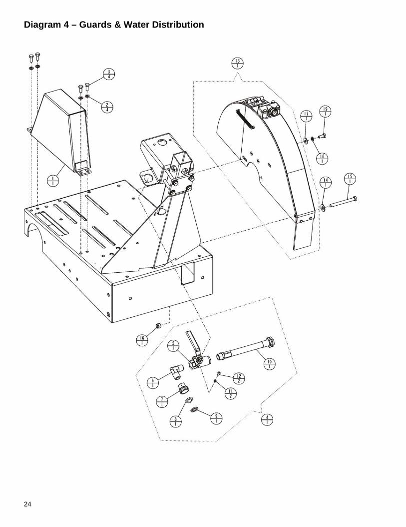
Diagram 4 – Guards & Water Distribution BILL OF MATERIAL INDEX P/N DESCRIPTION QTY 1 502469801 Guard, Belt 1 2 020785 Lockwasher, Split .313 4 3 020313 Capscrew, Hex Hd .312-18UNC x .75 4 4 174992 Water Valve Assy, MC18 1 5 139021 Water Valve 1 6 169196 Elbow, 1/2NPT Male x 90° Brass 1 7 539300267 Hose Adapter 1 8 045640 Filter Washer 1 9 040254 Washer, Hose 1 10 139616 Hose Assy, Water - MC18 1 11 020782 Lockwasher, Split #10 2 12 196039 Screw, Rd Hd Mach 10-24 x .500 Cross Z/P 2 13 195129 Assy, Blade Guard - 18in Husq Gray 1 14 020743 Washer, Flat .375 Dia 1 15 020233 Capscrew, Hex Hd .375-16UNC x 3.75 1 16 020199 Locknut, Fiber .375-16UNC 1 17 020742 Washer, Flat .313 Dia 1 18 020785 Lockwasher, Split .313 1 19 020313 Capscrew, Hex Hd .312-18UNC x .75 1
26
Diagram 5 – Blade Guard

27
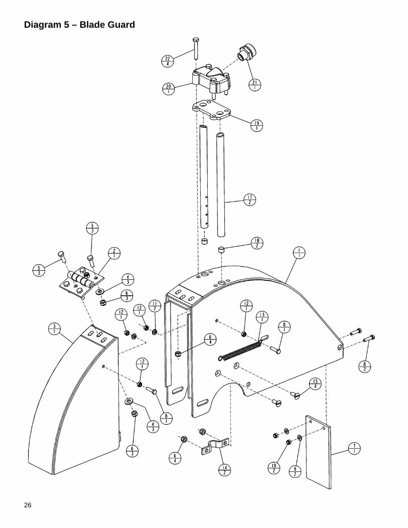
Diagram 5 – Blade Guard BILL OF MATERIAL INDEX P/N DESCRIPTION QTY 1 50244701 Rear Guard Weldment - 18 Inch Husq Gray 1 2 195127 Hinge 1 3 139596 Front Guard Weldment, 18 Inch Husq Gray 1 4 173059 Washer, Flat M8 6 5 167478 Capscrew, Hex Hd M8 x 1.25 x 25mm 6 6 139738 Locknut, Fiber M8 x 1.25 6 7 139098 Splash Flap 1 8 167761 Capscrew, Hex Hd M5 x 0.8 x 20mm 4 9 173047 Washer, Flat M5 2 10 172316 Locknut, Fiber M5 x 0.8 2 11 020782 Lockwasher, Split #10 2 12 172011 Nut, Hex Hd M5 x 0.80 4 13 040330 Spring, .375 OD x .054 Dia 1 14 049212 Clamp, Water Tube 2 15 167818 Capscrew, Slot Flat Hd M6 x 1.0 x 16mm 4 16 139745 Locknut, Fiber M6 x 1.0 8 17 167046 Water Tube, 18 Inch 2 18 020864 Plug, Soc Hd 1/8 NPT Brass 2 19 139051 Gasket, Water Manifold 1 20 139045 Water Manifold, Machined 1 21 040275 Adapter, 3/8 NPT x Male Garden Hose 1 22 167551 Capscrew, Hex Hd M6 x 1.0 x 40mm 4
28
Diagram 6 – Engine & Bladeshaft

29
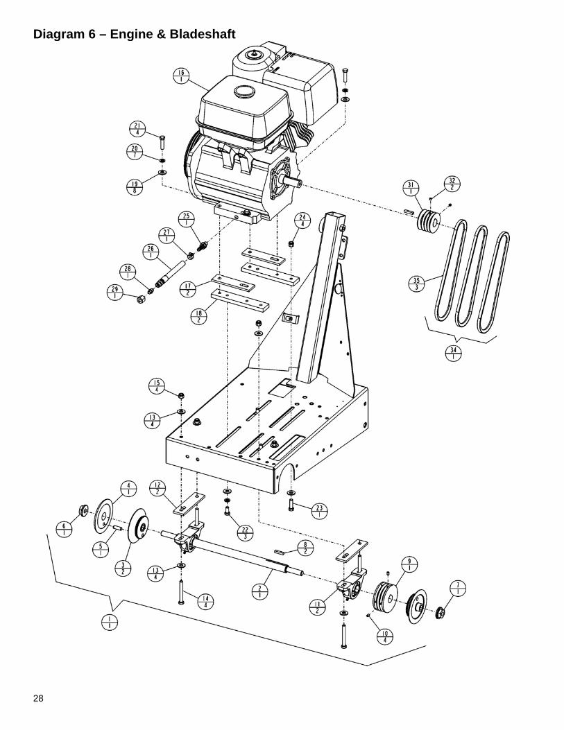
Diagram 6 – Engine & Bladeshaft BILL OF MATERIAL INDEX P/N DESCRIPTION QTY 1 174973 Group, Bladeshaft R&L 4.5 (9H,13H) 1 2 177569 Bladeshaft Assy, Complete (9H,13H) 1 3 167185 Collar, Inner 4.50 OD 2 4 167962 Collar, Outer 4.50 OD Assy 1 5 167964 Pin, Drive 1 6 167846 Nut, LH Thread, Bladeshaft 1 7 167847 Nut, RH Thread, Bladeshaft 1 8 020067 Key, Square .250 x 1.25 Lg 1 9 139300 Pulley Assy, 3GR 3V 3.65 (9H,13H) 1 10 020541 Screw, Set Soc Cup Pt .250-20UNC x .375 4 11 162633 Bearing, 1in Pillowblock BB 2 12 174962 Spacer, Bearing 2 13 020743 Washer, Flat .375 Dia 8 14 020330 Capscrew, Hex Hd .375-16UNC x 3.00 4 15 020199 Locknut, Fiber .375-16UNC 4 16 177958 Engine, 13HP Honda - Modified 1 -- 167751 Engine, 9HP Honda - Modified 1 17 174962 Spacer, Bearing (9R,13R,13H) 2 18 174736 Plate, Adapter (13H Only) 2 19 020743 Washer, Flat .375 Dia 8 20 020786 Lockwasher, Split .375 (13H Only) 7 21 020377 Capscrew, Hex Hd .375-16UNC x 1.50 (13H) 4 -- 020380 Capscrew, Hex Hd .375-16UNC x 1.75 ( 9H) 4 22 020322 Capscrew, Hex Hd .375-16UNC x .75 (13H) 3 23 048740 Capscrew, Hex Hd .375-16UNC x 1.25 (13H) 1 24 020199 Locknut, Fiber .375-16UNC 4 25 167133 Adapter, M12 x 10mm Hose Barb (9H,13H) 1 26 167305 Hose Assembly, Oil Drain 1 27 020049 Hose Clamp, Worm Drive 1 28 167306 Cap, Blanking 1 29 167622 Tube Nut, M16 1 30 174999 Assy, Cord 1 31 167746 Pulley Assy, 3G3V 2.65 Dia (w/ss) 1 32 020540 Screw, Set Soc Cup Pt .250-20UNC x .25 2 33 020067 Key, Square .250 x 1.25 Lg 1 34 139613 V-Belt, 3VX300 [set of 3](13H) 1 -- 139614 V-Belt, 3VX280 [set of 3]( 9H) 1 35 047455 V-Belt, 3VX300 (13H) 3 -- 058020 V-Belt, 3VX280 ( 9H) 1
30
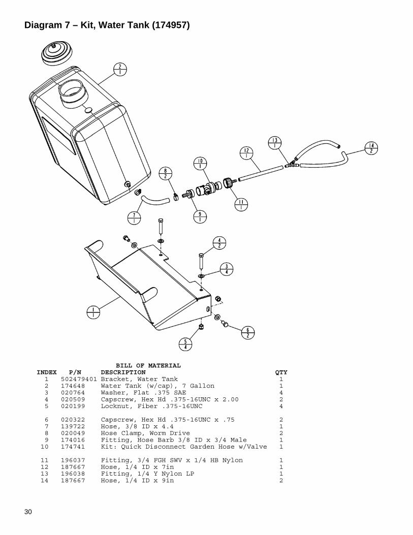
Diagram 7 – Kit, Water Tank (174957)
BILL OF MATERIAL INDEX P/N DESCRIPTION QTY 1 502479401 Bracket, Water Tank 1 2 174648 Water Tank (w/cap), 7 Gallon 1 3 020764 Washer, Flat .375 SAE 4 4 020509 Capscrew, Hex Hd .375-16UNC x 2.00 2 5 020199 Locknut, Fiber .375-16UNC 4 6 020322 Capscrew, Hex Hd .375-16UNC x .75 2 7 139722 Hose, 3/8 ID x 4.4 1 8 020049 Hose Clamp, Worm Drive 2 9 174016 Fitting, Hose Barb 3/8 ID x 3/4 Male 1 10 174741 Kit: Quick Disconnect Garden Hose w/Valve 1 11 196037 Fitting, 3/4 FGH SWV x 1/4 HB Nylon 1 12 187667 Hose, 1/4 ID x 7in 1 13 196038 Fitting, 1/4 Y Nylon LP 1 14 187667 Hose, 1/4 ID x 9in 2

NOTES / NOTAS:
Customer Service: 800-288-5040Customer Serv. Fax: 800-825-0028
Printed in the USA
DUST WARNING
Cutting, especially when DRY cutting, generates dust that comes from the material being cut,which frequently contains silica. Silica is a basic component of sand, quartz, brick clay, granite andnumerous other minerals and rocks. Exposure to excessive amount of such dust can cause:
Respiratory diseases (affecting your ability to breath), including chronic bronchitis, silicosisand pulmonary fibrosis from exposure to silica. These diseases may be fatal;
Skin irritation and rash; and
Cancer according to NTP* and IARC*National* Toxicology Program / International Agency for Research on Cancer
Take precautionary steps
Avoid inhalation of and skin contact with dust, mist and fumes;
Wet cut when feasible, to minimize dust;
Wear and ensure that all bystanders wear appropriate respiratory protection such as dustmasks designed to filter out microscopic particles. (See OSHA 29 CFR Part 1910.1200)
California Prop 65 Warning:Use of this product can cause exposure to materials known to the State of California to cause cancer
and/or birth defects or other reproductive harm.
Husqvarna Construction Products N. A.Corporate Office
17400 West 119th StreetOlathe, Kansas 66061
Tel. 913-928-1000Fax 913-438-7951