Embed Size (px)
Citation preview

OPERATOR’S & MAINTENANCE MANUAL
B33-01-0104 Rev. 4 August 2012
HAULOTTE GROUP
2
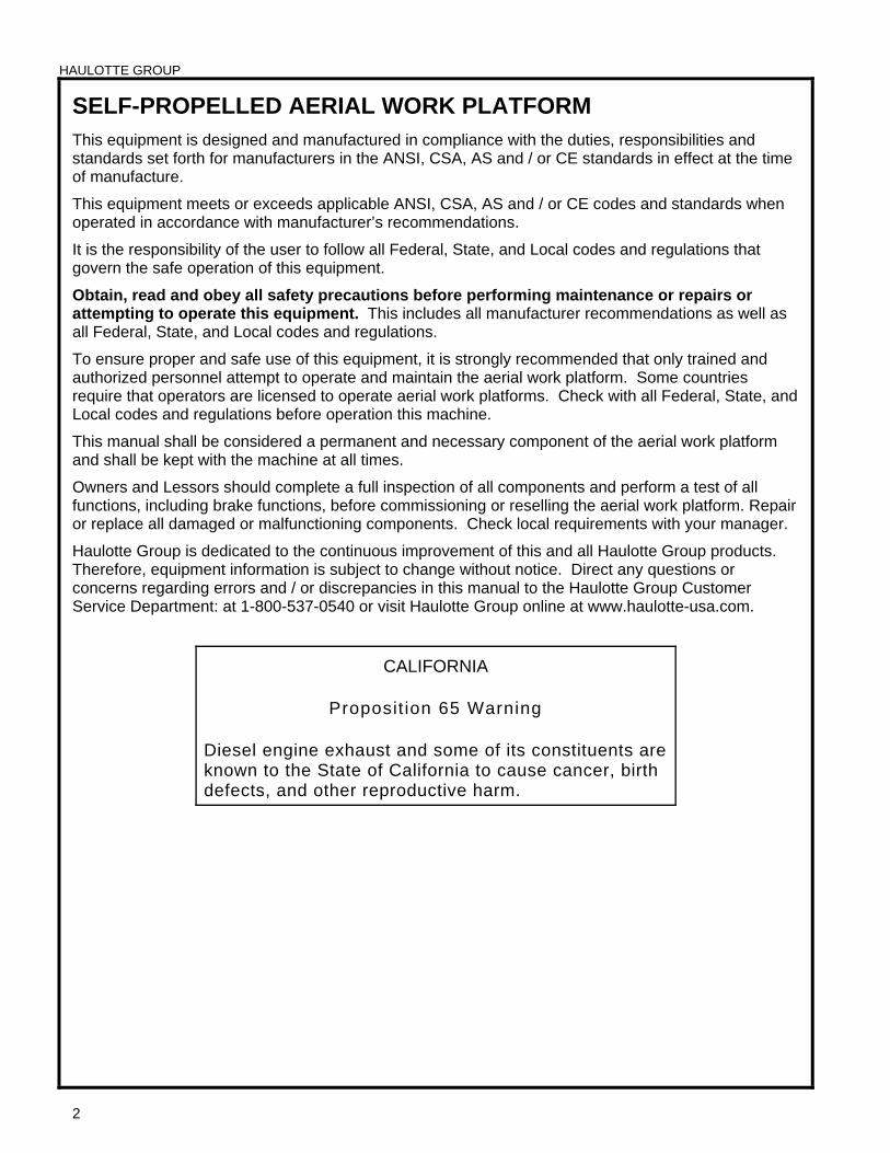
SELF-PROPELLED AERIAL WORK PLATFORM This equipment is designed and manufactured in compliance with the duties, responsibilities and standards set forth for manufacturers in the ANSI, CSA, AS and / or CE standards in effect at the time of manufacture.
This equipment meets or exceeds applicable ANSI, CSA, AS and / or CE codes and standards when operated in accordance with manufacturer’s recommendations.
It is the responsibility of the user to follow all Federal, State, and Local codes and regulations that govern the safe operation of this equipment.
Obtain, read and obey all safety precautions before performing maintenance or repairs or attempting to operate this equipment. This includes all manufacturer recommendations as well as all Federal, State, and Local codes and regulations.
To ensure proper and safe use of this equipment, it is strongly recommended that only trained and authorized personnel attempt to operate and maintain the aerial work platform. Some countries require that operators are licensed to operate aerial work platforms. Check with all Federal, State, and Local codes and regulations before operation this machine.
This manual shall be considered a permanent and necessary component of the aerial work platform and shall be kept with the machine at all times.
Owners and Lessors should complete a full inspection of all components and perform a test of all functions, including brake functions, before commissioning or reselling the aerial work platform. Repair or replace all damaged or malfunctioning components. Check local requirements with your manager.
Haulotte Group is dedicated to the continuous improvement of this and all Haulotte Group products. Therefore, equipment information is subject to change without notice. Direct any questions or concerns regarding errors and / or discrepancies in this manual to the Haulotte Group Customer Service Department: at 1-800-537-0540 or visit Haulotte Group online at www.haulotte-usa.com.
CALIFORNIA
Proposit ion 65 Warning
Diesel engine exhaust and some of its constituents are known to the State of California to cause cancer, birth defects, and other reproductive harm.
HAULOTTE GROUP
3
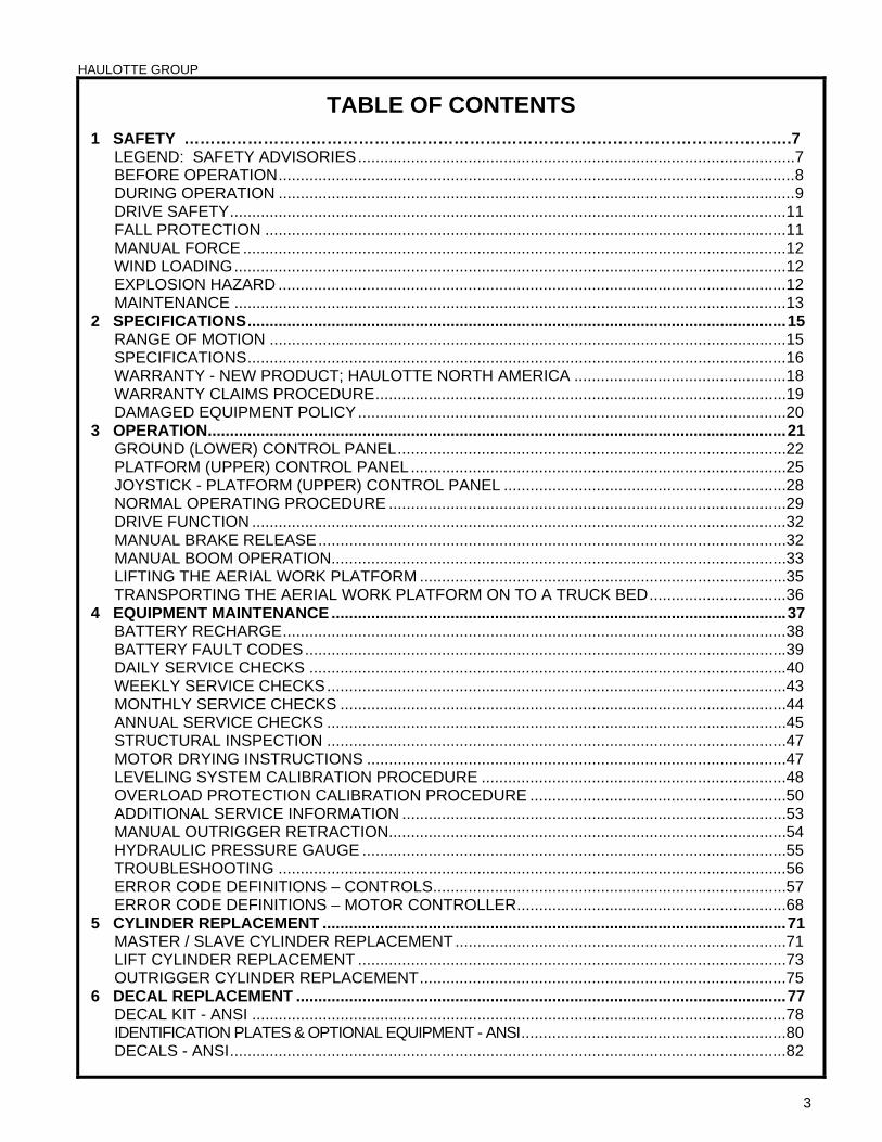
TABLE OF CONTENTS 1 SAFETY …………………………………………………………………………………………………….7
LEGEND: SAFETY ADVISORIES...................................................................................................7 BEFORE OPERATION.....................................................................................................................8 DURING OPERATION .....................................................................................................................9 DRIVE SAFETY..............................................................................................................................11 FALL PROTECTION ......................................................................................................................11 MANUAL FORCE ...........................................................................................................................12 WIND LOADING.............................................................................................................................12 EXPLOSION HAZARD ...................................................................................................................12 MAINTENANCE .............................................................................................................................13
2 SPECIFICATIONS..........................................................................................................................15 RANGE OF MOTION .....................................................................................................................15 SPECIFICATIONS..........................................................................................................................16 WARRANTY - NEW PRODUCT; HAULOTTE NORTH AMERICA ................................................18 WARRANTY CLAIMS PROCEDURE.............................................................................................19 DAMAGED EQUIPMENT POLICY.................................................................................................20
3 OPERATION...................................................................................................................................21 GROUND (LOWER) CONTROL PANEL........................................................................................22 PLATFORM (UPPER) CONTROL PANEL.....................................................................................25 JOYSTICK - PLATFORM (UPPER) CONTROL PANEL ................................................................28 NORMAL OPERATING PROCEDURE ..........................................................................................29 DRIVE FUNCTION .........................................................................................................................32 MANUAL BRAKE RELEASE..........................................................................................................32 MANUAL BOOM OPERATION.......................................................................................................33 LIFTING THE AERIAL WORK PLATFORM ...................................................................................35 TRANSPORTING THE AERIAL WORK PLATFORM ON TO A TRUCK BED...............................36
4 EQUIPMENT MAINTENANCE .......................................................................................................37 BATTERY RECHARGE..................................................................................................................38 BATTERY FAULT CODES.............................................................................................................39 DAILY SERVICE CHECKS ............................................................................................................40 WEEKLY SERVICE CHECKS........................................................................................................43 MONTHLY SERVICE CHECKS .....................................................................................................44 ANNUAL SERVICE CHECKS ........................................................................................................45 STRUCTURAL INSPECTION ........................................................................................................47 MOTOR DRYING INSTRUCTIONS ...............................................................................................47 LEVELING SYSTEM CALIBRATION PROCEDURE .....................................................................48 OVERLOAD PROTECTION CALIBRATION PROCEDURE ..........................................................50 ADDITIONAL SERVICE INFORMATION .......................................................................................53 MANUAL OUTRIGGER RETRACTION..........................................................................................54 HYDRAULIC PRESSURE GAUGE ................................................................................................55 TROUBLESHOOTING ...................................................................................................................56 ERROR CODE DEFINITIONS – CONTROLS................................................................................57 ERROR CODE DEFINITIONS – MOTOR CONTROLLER.............................................................68
5 CYLINDER REPLACEMENT .........................................................................................................71 MASTER / SLAVE CYLINDER REPLACEMENT...........................................................................71 LIFT CYLINDER REPLACEMENT .................................................................................................73 OUTRIGGER CYLINDER REPLACEMENT...................................................................................75
6 DECAL REPLACEMENT ...............................................................................................................77 DECAL KIT - ANSI .........................................................................................................................78 IDENTIFICATION PLATES & OPTIONAL EQUIPMENT - ANSI............................................................80 DECALS - ANSI..............................................................................................................................82
HAULOTTE GROUP
4
7 OPTIONAL EQUIPMENT ...............................................................................................................87 MATERIAL LIFT HOOK ................................................................................................................. 88 PLATFORM ROTATOR................................................................................................................. 91
8 MATERIAL SAFETY.......................................................................................................................93 LEAD ACID BATTERIES, WET, FILLED WITH ACID – UN 2794................................................. 93 POWERFLOW™ AW HVI HYDRAULIC OIL ................................................................................. 98
9 ANSI REPRINT.............................................................................................................................105 INSPECTION FORM FOR HAULOTTE AERIAL WORK PLATFORMS ..........................................117
LIST OF TABLES
TABLE 1-1. MINIMUM SAFE APPROACH DISTANCES .....................................................................9 TABLE 1-2. BEAUFORT SCALE ........................................................................................................12 TABLE 4-1. BATTERY CHARGER FAULT CODES ...........................................................................39 TABLE 4-2. TROUBLE SHOOTING....................................................................................................56 TABLE 4-3 ERROR CODE DEFINITIONS.........................................................................................57 TABLE 4-4. ERROR CODE DEFINITIONS - MOTOR CONTROLLER ..............................................68 TABLE 9-1. MINIMUM SAFE APPROACH DISTANCES .................................................................115
HAULOTTE GROUP
5
LIST OF ILLUSTRATIONS Figure 2-1. Range of Motion............................................................................................................15 Figure 3-1. Ground (Lower) Control Panel ....................................................................................22 Figure 3-2. Platform (Upper) Control Panel ...................................................................................25 Figure 3-3. Platform Controls Joystick ..........................................................................................28 Figure 3-4. Boom Travel Latches ...................................................................................................29 Figure 3-5. Outrigger Control Panel ...............................................................................................30 Figure 3-6. Drive Speed Selector....................................................................................................32 Figure 3-7. Manual Break Release..................................................................................................32 Figure 3-8. Hand Pump Controls for Manual Operation...............................................................33 Figure 3-9. Location of Lift Cylinders for Manual Boom Lowering .............................................34 Figure 3-10. Location of Manual Lowering Valves..........................................................................34 Figure 3-11. Lifting the Aerial Work Platform..................................................................................35 Figure 3-12. Transport the Aerial Work Platform ............................................................................36 Figure 4-1. Battery Charger Faceplate ...........................................................................................38 Figure 4-2. Outrigger Position Switch............................................................................................41 Figure 4-3. Hydraulic Reservoir......................................................................................................42 Figure 4-4. Wheel Nut Tightening Sequence.................................................................................44 Figure 4-5. Display Run Time Hours ..............................................................................................45 Figure 4-6. Machine Position for Slew Ring Measurement ..........................................................46 Figure 4-7. Slew Ring Position Measurement ...............................................................................46 Figure 4-8. Platform Position After Rotation .................................................................................46 Figure 4-9. Position Machine for Leveling.....................................................................................48 Figure 4-10. Level Sensor Digitally Based.......................................................................................48 Figure 4-11. Level Sensor Pendulum Based ...................................................................................48 Figure 4-12. Ground (Lower) Control Panel for Leveling System .................................................49 Figure 4-13. Platform Position ..........................................................................................................50 Figure 4-14. Ground (Lower) Control Panel for Overload Protection ...........................................50 Figure 4-15. Manual Outrigger Control Wire Harness ....................................................................54 Figure 4-16. Bottom Side of the Ground (lower) Control Box. ......................................................54 Figure 4-17. Hydraulic Power Unit....................................................................................................54 Figure 4-18. Attaching the Pressure Gauge to the Hydraulic Power Unit. ...................................55 Figure 4-19. Motor Controller............................................................................................................68 Figure 5-1. Location of Master Cylinder ........................................................................................71 Figure 5-2. Location of Slave Cylinder...........................................................................................72 Figure 5-3. Location of Manual Lowering Valves for Lift Cylinder Replacement ......................73 Figure 5-4. Push “Button” Lowering Valve ...................................................................................73 Figure 5-5. Lift Cylinder Replacement ...........................................................................................73 Figure 5-6. Outrigger Cylinder Replacement.................................................................................75 Figure 5-7. Cylinder Valve Removal ...............................................................................................75 Figure 7-1. Disconnect Plug from Load Sense Module................................................................88 Figure 7-2. Remove Platform (Upper) Control Box.......................................................................88 Figure 7-3. Loopback plug ..............................................................................................................88 Figure 7-4. Platform Removal .........................................................................................................89 Figure 7-5. Material Lifting Hook Installation ................................................................................89 Figure 7-6. Material Lift “Stowed” Position ...................................................................................90 Figure 7-7. Material Lift “In Use” Position .....................................................................................90 Figure 7-8. Manual Platform Rotator ..............................................................................................91 Figure 9-1. Minimum Safe Approach Distance............................................................................114
HAULOTTE GROUP
6
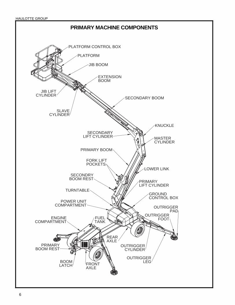
PRIMARY MACHINE COMPONENTS
REAR
JIB LIFT
OUTRIGGER
LEG
ENGINE
AXLE
CYLINDER
OUTRIGGER
TANK
MASTER
CYLINDER
OUTRIGGER
POCKETS
COMPARTMENT
LATCHAXLE
CYLINDER
LIFT CYLINDER
FRONT
BOOM REST
SECONDARY BOOM
CYLINDERSLAVE
EXTENSION
KNUCKLE
PRIMARY
PRIMARY
BOOM
TURNTABLE
SECONDRY
BOOM
PRIMARY BOOM
JIB BOOM
BOOM REST
OUTRIGGERPAD
LOWER LINK
PLATFORM
FOOTFUEL
FORK LIFT.
PLATFORM CONTROL BOX
POWER UNITCOMPARTMENT
GROUNDCONTROL BOX
SECONDARYLIFT CYLINDER
HAULOTTE GROUP 1 SAFETY
7
1 SAFETY Proper training is required for the safe operation of any mechanical device. Failure to follow all instructions and safety precautions in this manual and attached to the aerial work platform will result in death or personal injury.
Prior to Operation:
Read, understand and obey all instructions and safety precautions in this manual and attached to the aerial work platform.
Read, understand and obey all Federal, State and Local codes and regulations.
Become familiar with the proper use of all controls.
Inexperienced users should receive instruction by a qualified instructor before attempting to operate or maintain the aerial work platform.
The use of intelligence and common sense is the best practice when following any safety policy.
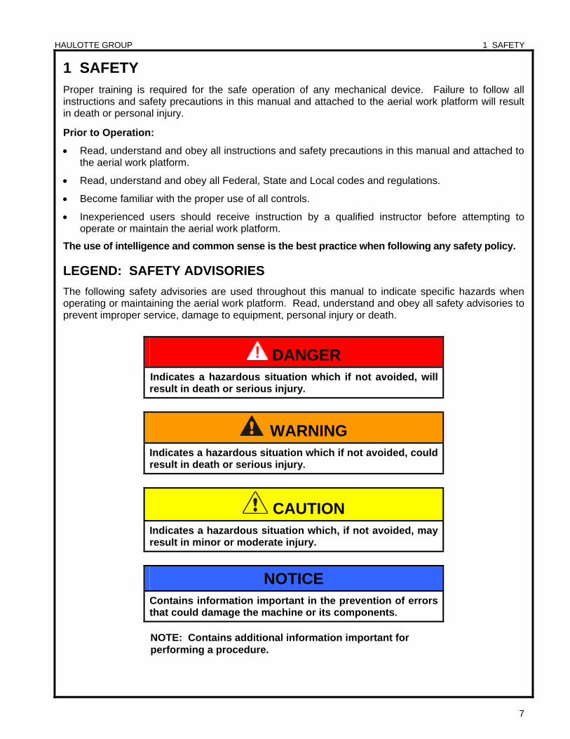
LEGEND: SAFETY ADVISORIES
The following safety advisories are used throughout this manual to indicate specific hazards when operating or maintaining the aerial work platform. Read, understand and obey all safety advisories to prevent improper service, damage to equipment, personal injury or death.
DANGER Indicates a hazardous situation which if not avoided, will result in death or serious injury.
WARNING Indicates a hazardous situation which if not avoided, could result in death or serious injury.
CAUTION Indicates a hazardous situation which, if not avoided, may result in minor or moderate injury.
NOTICE Contains information important in the prevention of errors that could damage the machine or its components.
NOTE: Contains additional information important for performing a procedure.
HAULOTTE GROUP 1 SAFETY
8
BEFORE OPERATION
Ensure the following general safety precautions are followed before operating the aerial work platform:
ALWAYS inspect the usage area for potential hazards, such as unstable or unlevel surfaces, overhead obstructions and electrically charged wires or conductors. ALWAYS watch for moving vehicles in the operating area.
ALWAYS conduct a thorough visual inspection of the aerial work platform before operation. Check for damaged or worn parts, hydraulic leaks, damaged wiring, loose wiring conductors, damaged outriggers, low tire pressure, uneven tire wear or tire damage. Check for any improperly operating components. NEVER operate the aerial work platform if any damage is observed or suspected. Repair damaged or malfunctioning equipment before operation.
ALWAYS wear proper clothing. Wear protective equipment as required by Federal, State and Local codes and regulations. Keep loose clothing, jewelry, gloves and hair away from moving parts.
ALWAYS wear a Safety Harness and energy-absorbing Lanyard, such as the Safety Harness and Lanyard available through the Haulotte Group.
ALWAYS inspect platform floor and outrigger footpads for mud, grease, debris or other foreign material. ALWAYS remove any such material from the aerial work platform before operation.
ALWAYS RED tag any part of this machine known or suspected to be damaged or malfunctioning. ALWAYS remove a malfunctioning, damaged or defective aerial work platform from service. NEVER operate an aerial work platform that has any known or suspected defect.
ALWAYS comply with the instructions found in Safety and / or Service Bulletins distributed by the manufacturer / factory. Bulletins may contain critical procedures that supersede the information contained in this manual.
NEVER operate this aerial work platform while under the influence of drugs or alcohol, while taking prescription medications that may leave the operator drowsy or prone to dizziness, or while feeling ill.
NEVER modify, alter or change the aerial work platform in any way that would affect its original design or operation.
NEVER deface, modify or obscure any decals or markings on the aerial work platform.
NEVER operate this aerial work platform in any way for which it is not intended.
NEVER operate this aerial work platform in explosive or flammable environments.
Before attempting aerial work platform operations, operator(s) should:
Attend a training program as required by all Federal, State, and Local codes and regulations.
Obtain, read and obey all safety precautions as indicated by manufacturer’s recommendations and all Federal, State and Local codes and regulations.
Become familiar with the location and use of all controls.
Verify that there are no overhead obstructions or live power sources in the work area that could interfere with the safe operation of the aerial work platform.
Cordon off the area surrounding the aerial work platform to keep personnel, vehicles and moving equipment away from the aerial work platform while in use.
Position the aerial work platform on a firm and level surface.
Conduct a pre-operation inspection by performing all recommended daily service checks. Refer to the “Equipment Maintenance” section of this manual.
HAULOTTE GROUP 1 SAFETY
9
DURING OPERATION
Ensure the following general safety precautions are followed while operating the aerial work platform:
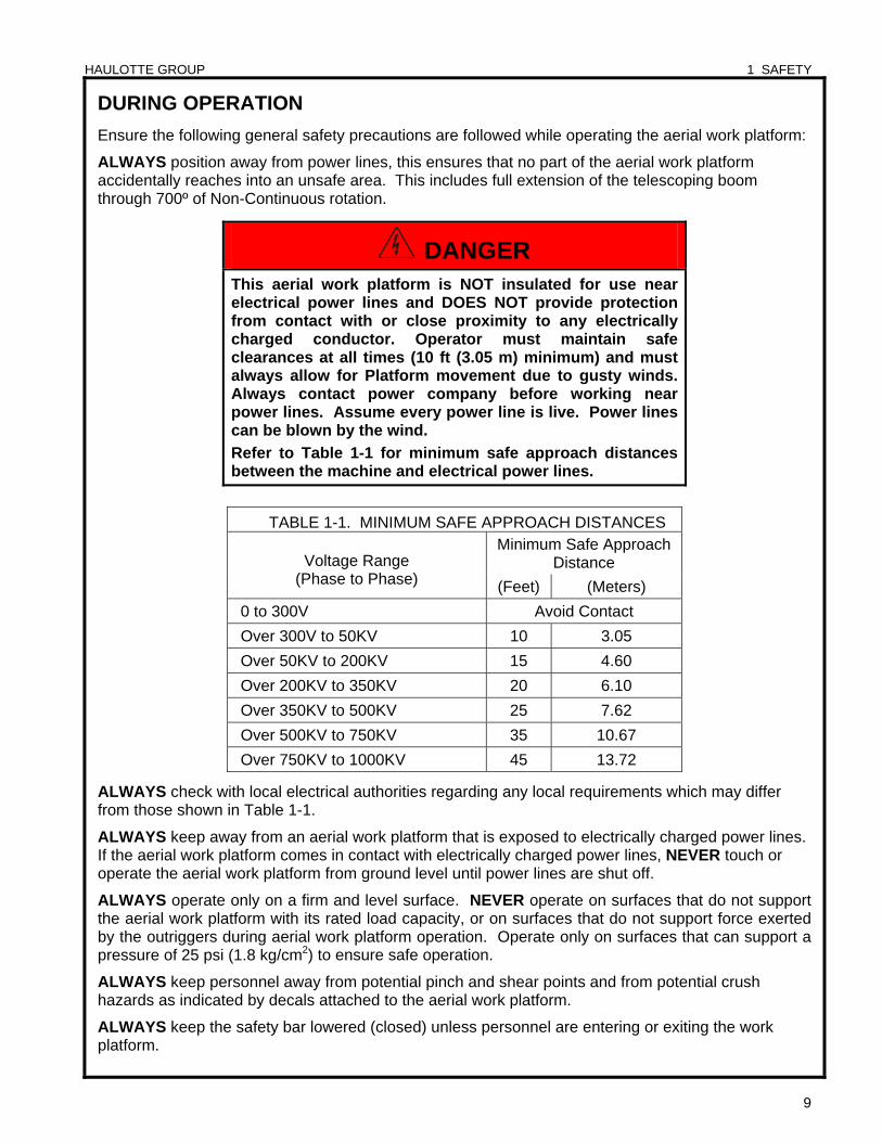
ALWAYS position away from power lines, this ensures that no part of the aerial work platform accidentally reaches into an unsafe area. This includes full extension of the telescoping boom through 700º of Non-Continuous rotation.
ALWAYS check with local electrical authorities regarding any local requirements which may differ from those shown in Table 1-1.
ALWAYS keep away from an aerial work platform that is exposed to electrically charged power lines. If the aerial work platform comes in contact with electrically charged power lines, NEVER touch or operate the aerial work platform from ground level until power lines are shut off.
ALWAYS operate only on a firm and level surface. NEVER operate on surfaces that do not support the aerial work platform with its rated load capacity, or on surfaces that do not support force exerted by the outriggers during aerial work platform operation. Operate only on surfaces that can support a pressure of 25 psi (1.8 kg/cm2) to ensure safe operation.
ALWAYS keep personnel away from potential pinch and shear points and from potential crush hazards as indicated by decals attached to the aerial work platform.
ALWAYS keep the safety bar lowered (closed) unless personnel are entering or exiting the work platform.
DANGER This aerial work platform is NOT insulated for use near electrical power lines and DOES NOT provide protection from contact with or close proximity to any electrically charged conductor. Operator must maintain safe clearances at all times (10 ft (3.05 m) minimum) and must always allow for Platform movement due to gusty winds. Always contact power company before working near power lines. Assume every power line is live. Power lines can be blown by the wind.
Refer to Table 1-1 for minimum safe approach distances between the machine and electrical power lines.
TABLE 1-1. MINIMUM SAFE APPROACH DISTANCES Minimum Safe Approach
Distance Voltage Range (Phase to Phase) (Feet) (Meters)
0 to 300V Avoid Contact
Over 300V to 50KV 10 3.05
Over 50KV to 200KV 15 4.60
Over 200KV to 350KV 20 6.10
Over 350KV to 500KV 25 7.62
Over 500KV to 750KV 35 10.67
Over 750KV to 1000KV 45 13.72
HAULOTTE GROUP 1 SAFETY
10
DURING OPERATION (CONTINUED) ALWAYS use a three (3) point contact (both hands and one foot) when entering or exiting the work platform.
ALWAYS wear proper footgear. ALWAYS keep the platform free of debris.
ALWAYS keep personnel and obstructions clear of the aerial work platform when repositioning the boom or platform.
ALWAYS cordon the area surrounding the outriggers to keep personnel, vehicles and moving equipment away from the aerial work platform while in use.
ALWAYS stay clear of overhead obstructions, including wires and cables.
ALWAYS disengage aerial work platform travel latches before raising aerial work platform sections and reengage aerial work platform travel latches before transporting.
ALWAYS exercise caution when rotating the boom from the ground (lower) control panel. ALWAYS watch for personnel inside the radius of the turntable and boom arm when rotating from the ground (lower) or platform (upper) controls.
ALWAYS remove personnel from the aerial work platform before attempting to free an elevated platform that has become caught or snagged on an adjacent structure or obstacle.
NEVER operate the aerial work platform from a position on a truck-bed, trailer, floating vessel or scaffolding without written approval from the manufacturer / factory.
ALWAYS maintain joystick enable lever during drive operation.
NEVER allow electrode contact with any part of the aerial work platform while welding from the platform. NEVER use the aerial work platform as a ground for welding.
NEVER operate without the outriggers fully extended or when the aerial work platform is not level.
NEVER position an elevated platform against another object to steady the platform.
NEVER override or bypass the manufacturer’s safety devices.
NEVER attach a safety harness to an adjacent structure, pole, or to nearby equipment while working from the platform.
NEVER raise the outriggers with materials or personnel on board, or while platform is raised or extended.
NEVER sit, stand or climb on platform railing. ALWAYS keep both feet firmly on the platform floor.
NEVER attempt to increase the working height with boxes, ladders, stools or any other materials.
NEVER operate this aerial work platform when exposed to high winds, thunderstorms, ice or any weather conditions that would compromise operator safety.
NEVER operate aerial work platform in conditions where wind speeds exceed 28 mph (12.5 m/sec or 45 km/h). Steady or gusty winds that exceed the recommended wind speed may affect stability and aerial work platform operation.
NEVER allow ropes, electric cords, hoses or other equipment to become entangled in the aerial work platform.
NEVER exceed the load limits set by the manufacturer / factory. Use only the material lifting hook, supplied as an option and manufactured by Haulotte Group when lifting materials. Safely stow all tools and equipment.
HAULOTTE GROUP 1 SAFETY
11
DURING OPERATION (CONTINUED)
NEVER exceed load ratings by transferring loads to the aerial work platform at elevated heights.
NEVER use the platform to lift a load that exceeds the platform dimensions. NEVER lift a load in such a way that the center of gravity is higher than the top guardrail of the platform.
NEVER modify the platform or carry materials that would increase the surface area of the platform. Increasing the area exposed to the wind may affect the aerial work platform stability. NEVER attach overhanging loads when raising or lowering the platform.
NEVER use the boom or platform to push or pull or to lift any part of the machine.
NEVER use the boom or platform to place a load against any structure, materials or equipment.
NEVER climb on the boom.
NEVER leave an elevated platform unattended.
NEVER leave the keys in the aerial work platform while unattended or not in use.
DRIVE SAFETY ALWAYS maintain an awareness of limited sight and blind spots when operating drive functions.
ALWAYS limit travel speed according to surface conditions, slope, location of personnel and obstructions and any other factors which may result in collision.
NEVER operate drive functions on slopes exceeding 45% (24°).
NEVER engage in stunt driving, horseplay or any other behavior considered unsafe according to employer, job site and all Federal, State, and Local codes and regulations.
NEVER operate the internal combustion engine in an area that is not properly ventilated.
NEVER fuel the internal combustion engine while smoking, or while near spark or open flame.
FALL PROTECTION
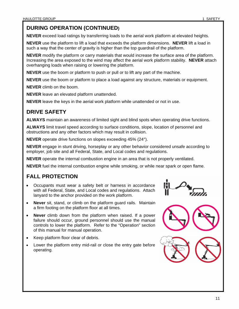
Occupants must wear a safety belt or harness in accordance with all Federal, State, and Local codes and regulations. Attach lanyard to the anchor provided on the work platform.
Never sit, stand, or climb on the platform guard rails. Maintain a firm footing on the platform floor at all times.
Never climb down from the platform when raised. If a power failure should occur, ground personnel should use the manual controls to lower the platform. Refer to the “Operation” section of this manual for manual operation.
Keep platform floor clear of debris.
Lower the platform entry mid-rail or close the entry gate before operating.
HAULOTTE GROUP 1 SAFETY
12
MANUAL FORCE Never push off or pull toward any object outside the platform.
Maximum allowable manual force is 90 lb. (400 N).
WIND LOADING Never operate the aerial work platform in strong or winds that exceed 28 mph (12.5 m/s) or 45
km/h). Never increase the surface area of the platform or the load. Increasing the area exposed to the wind will decrease the aerial work platform stability.
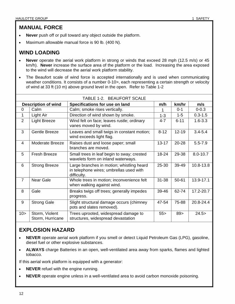
The Beaufort scale of wind force is accepted internationally and is used when communicating weather conditions. It consists of a number 0-10>, each representing a certain strength or velocity of wind at 33 ft (10 m) above ground level in the open. Refer to Table 1-2
TABLE 1-2. BEAUFORT SCALE
Description of wind Specifications for use on land m/h km/hr m/s 0 Calm Calm; smoke rises vertically. 1 0-1 0-0.3 1 Light Air Direction of wind shown by smoke. 1-3 1-5 0.3-1.5 2 Light Breeze Wind felt on face; leaves rustle; ordinary
vanes moved by wind. 4-7 6-11 1.6-3.3
3 Gentle Breeze Leaves and small twigs in constant motion; wind exceeds light flag.
8-12 12-19 3.4-5.4
4 Moderate Breeze Raises dust and loose paper; small branches are moved.
13-17 20-28 5.5-7.9
5 Fresh Breeze Small trees in leaf begin to sway; crested wavelets form on inland waterways.
18-24 29-38 8.0-10.7
6 Strong Breeze Large branches in motion; whistling heard in telephone wires; umbrellas used with difficulty.
25-30 39-49 10.8-13.8
7 Near Gale Whole trees in motion; inconvenience felt when walking against wind.
31-38 50-61 13.9-17.1
8 Gale Breaks twigs off trees; generally impedes progress.
39-46 62-74 17.2-20.7
9 Strong Gale Slight structural damage occurs (chimney pots and slates removed).
47-54 75-88 20.8-24.4
10> Storm, Violent Storm, Hurricane
Trees uprooted, widespread damage to structures, widespread devastation
55> 89> 24.5>
EXPLOSION HAZARD NEVER operate aerial work platform if you smell or detect Liquid Petroleum Gas (LPG), gasoline,
diesel fuel or other explosive substances.
ALWAYS charge Batteries in an open, well-ventilated area away from sparks, flames and lighted tobacco.
If this aerial work platform is equipped with a generator:
NEVER refuel with the engine running.
NEVER operate engine unless in a well-ventilated area to avoid carbon monoxide poisoning.
HAULOTTE GROUP 1 SAFETY
13
MAINTENANCE Ensure the following general safety precautions are followed while performing maintenance on the aerial work platform:
General Maintenance
ALWAYS perform maintenance procedures according to manufacturer’s guidelines. NEVER disregard or bypass proper maintenance procedures.
ALWAYS inspect hydraulic system to ensure that all lines, connectors and fittings are properly fastened and are in good condition.
ALWAYS turn the key switch to the “OFF” position and remove key before performing maintenance.
Whenever possible, ALWAYS perform maintenance with the boom and platform in a fully lowered, “stowed” position.
ALWAYS secure the boom before performing maintenance on hydraulic cylinders.
ALWAYS disconnect power to the hydraulic pump drive motor before making electrical checks to the hydraulic valves.
ALWAYS keep all mechanical parts properly adjusted and lubricated according to maintenance schedule and manufacturer / factory specifications. Refer to the “Equipment Maintenance” section of this manual.
ALWAYS perform a function check of operating controls before each use and after any repairs have been made.
ALWAYS locate and protect against possible pinch points before performing any maintenance or repairs. Be aware of personnel under, and around the aerial work platform.
ALWAYS use only manufacturer-approved parts to repair or maintain aerial work platform. If any portion of this aerial work platform is rebuilt or repaired, retesting is required in accordance with manufacturer / factory instructions.
ALWAYS maintain a safe distance while testing the hydraulic components. ALWAYS relieve hydraulic pressure before loosening or removing hydraulic components. NEVER test or operate the hydraulic components while personnel are near the aerial work platform.
NEVER allow water or foreign particles into the DC electric motor housing. Inclusion of water or foreign particles may cause serious damage to the motor. If the motor becomes wet, refer to the “Motor Drying Instructions” located in the Equipment Maintenance section of this manual, or contact the Haulotte Customer Service Department: at 1-800-537-0540 for proper drying instructions.
NEVER add unauthorized fluids to the hydraulic system or battery. NEVER mix hydraulic oils. Consult manufacturer specifications. Refer to the “Equipment Maintenance” section of this manual for hydraulic system maintenance procedures. Refer to the next page for Battery maintenance.
NEVER exceed the manufacturer’s recommended relief valve settings.
NEVER touch or allow metal tools to contact any components that are sensitive to static discharge. ALWAYS use static discharge prevention mats and grounding devices when handling electronic components.
NEVER adjust, repair, replace or bypass any hydraulic or electrical control or safety device. These include, but are not limited to; hydraulic load control and flow control valves, solenoid valves and limit switches. ALWAYS consult an authorized Haulotte Group technician by contacting the Customer Service Department: at 1-800-537-0540 if repairs are necessary.
NEVER modify, alter or change the aerial work platform without first consulting an authorized Haulotte Group technician, and NEVER in any way that would affect its original design or operation.
HAULOTTE GROUP 1 SAFETY
14
MAINTENANCE (CONTINUED)
Battery Maintenance
Ensure the following general safety precautions are followed when performing battery maintenance on the aerial work platform:
ALWAYS check the battery fluid level daily.
ALWAYS wear safety glasses when working with or near batteries.
ALWAYS avoid contact with battery acid. Battery acid causes serious burns and should be kept away from skin or eyes. If contact occurs, flush with water and consult a physician immediately.
ALWAYS disconnect ground cable first when removing battery.
ALWAYS connect ground cable last when installing battery.
ALWAYS charge batteries in open, well-ventilated areas.
ALWAYS replace batteries using only parts recommended by manufacturer / factory. ALWAYS use only batteries with sealed caps over cells.
NEVER smoke while servicing batteries.
NEVER charge batteries near flammable materials.
NEVER allow batteries to overcharge and boil.
NEVER short across battery posts to check for current. NEVER break a live circuit at the battery.
NEVER disconnect battery from charger while charger is connected to a live power source.
NEVER jump-start other vehicles using the aerial work platform batteries.
HAULOTTE GROUP 2 SPECIFICATIONS
15
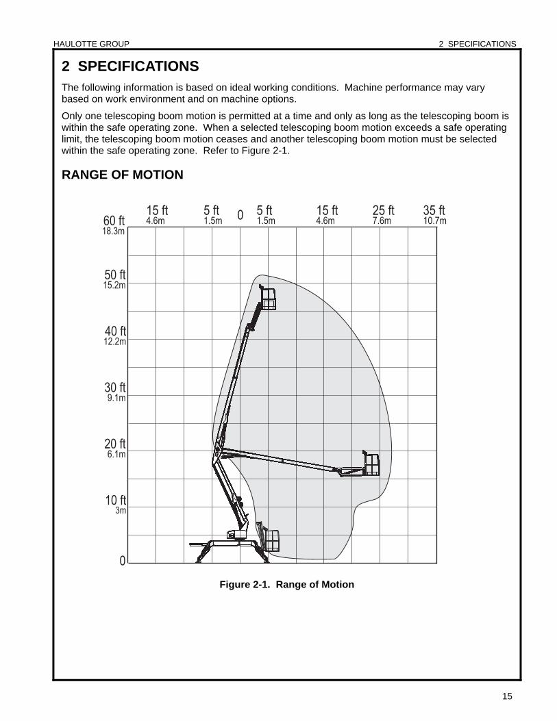
2 SPECIFICATIONS The following information is based on ideal working conditions. Machine performance may vary based on work environment and on machine options.
Only one telescoping boom motion is permitted at a time and only as long as the telescoping boom is within the safe operating zone. When a selected telescoping boom motion exceeds a safe operating limit, the telescoping boom motion ceases and another telescoping boom motion must be selected within the safe operating zone. Refer to Figure 2-1.
RANGE OF MOTION
Figure 2-1. Range of Motion
HAULOTTE GROUP 2 SPECIFICATIONS
16
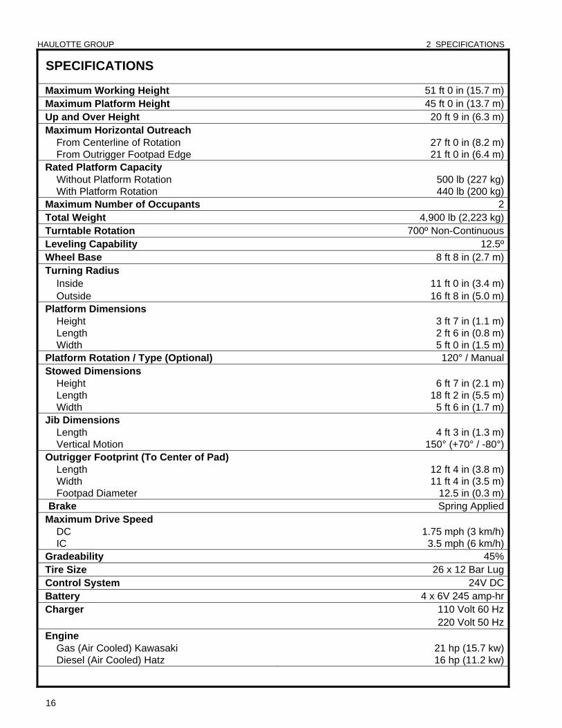
SPECIFICATIONS
Maximum Working Height 51 ft 0 in (15.7 m) Maximum Platform Height 45 ft 0 in (13.7 m) Up and Over Height 20 ft 9 in (6.3 m) Maximum Horizontal Outreach From Centerline of Rotation 27 ft 0 in (8.2 m) From Outrigger Footpad Edge 21 ft 0 in (6.4 m) Rated Platform Capacity Without Platform Rotation 500 lb (227 kg) With Platform Rotation 440 lb (200 kg) Maximum Number of Occupants 2 Total Weight 4,900 lb (2,223 kg) Turntable Rotation 700º Non-Continuous Leveling Capability 12.5º Wheel Base 8 ft 8 in (2.7 m) Turning Radius Inside 11 ft 0 in (3.4 m) Outside 16 ft 8 in (5.0 m) Platform Dimensions Height 3 ft 7 in (1.1 m) Length 2 ft 6 in (0.8 m) Width 5 ft 0 in (1.5 m) Platform Rotation / Type (Optional) 120° / Manual Stowed Dimensions Height 6 ft 7 in (2.1 m) Length 18 ft 2 in (5.5 m) Width 5 ft 6 in (1.7 m) Jib Dimensions Length 4 ft 3 in (1.3 m) Vertical Motion 150° (+70° / -80°) Outrigger Footprint (To Center of Pad) Length 12 ft 4 in (3.8 m) Width 11 ft 4 in (3.5 m) Footpad Diameter 12.5 in (0.3 m) Brake Spring Applied
Maximum Drive Speed DC 1.75 mph (3 km/h) IC 3.5 mph (6 km/h) Gradeability 45% Tire Size 26 x 12 Bar Lug Control System 24V DC Battery 4 x 6V 245 amp-hr Charger 110 Volt 60 Hz 220 Volt 50 Hz Engine Gas (Air Cooled) Kawasaki 21 hp (15.7 kw) Diesel (Air Cooled) Hatz 16 hp (11.2 kw)

HAULOTTE GROUP 2 SPECIFICATIONS
17
SPECIFICATIONS (CONTINUED) Hydraulic Pressure 3,000 psi (207 bar) (20,684 kPa)
Reservoir Capacity 4.3 Gallons (16.3 L)
Hydraulic System Capacity 6.3 Gallons (23.9 L)
Hydraulic Oil (Standard) HVI AW32
Maximum Noise Level DC Mode – Ground (Lower) 60 dBA DC Mode – Platform (Upper) 55 dBA Engine Mode – Ground (Ground) 70 dBA Engine Mode – Platform (Upper 65 dBA Function Speeds Boom - Primary Primary, Up - Fast 22-26 sec Primary, Up - Slow 54-58 sec Primary, Down – Fast 22-26 sec Primary, Down - Slow 89-93 sec Boom - Secondary Secondary Up - Fast 20-24 sec Secondary Up - Slow 38-42 sec Secondary Down - Fast 32-36 sec Secondary Down - Slow 74-78 sec Boom - Jib Jib, Up – Fast 8-12 sec Jib, Up - Slow 12-16 sec Jib, Down - Fast 20-24 sec Jib, Down - Slow 38-42 sec Extension Boom Boom Extend - Fast 24-28 sec Boom Extend - Slow 48-52 sec Boom Retract - Fast 28-32 sec Boom Retract - Slow 58-62 sec Turntable 700° Non Continuous Rotation Turntable Rotation - Fast 194-198 sec Turntable Rotation - Slow 326-330 sec Platform Platform Compensation - Up - Fast 10-14 sec Platform Compensation - Up - Slow 18-22 sec Platform Compensation - Down - Fast 10-14 sec Platform Compensation - Down - Slow 14-18 sec Outrigger (Auto Level) Outrigger Extend 18-22 sec Outrigger Retract 30-34 sec Localized (Foot Plate) Pressure per Outrigger 25 psi (1.8 kg/cm2) (176.5 kPa)
Maximum Pressure per Tire - Floor Loading 35 psi (2.5 bar)
Operating Temperature Range -20º to 110º Fahrenheit (-29º to 43º Celsius)
HAULOTTE GROUP 2 SPECIFICATIONS
18
WARRANTY - NEW PRODUCT; HAULOTTE NORTH AMERICA
Haulotte US Inc (Haulotte) warrants its new products made by it to be free from defects in material or workmanship for twelve (12) months under normal operational conditions from the warranty start date (delivery date).
In addition, Haulotte further warrants the structural elements of each new product made by it, as defined in its then current warranty policies and procedures, to be free from defects in material or workmanship for five (5) years from the warranty start date (delivery date).
Haulotte agrees to repair or replace at its own expense; at its facility in Frederick MD, or at an authorized repair facility designated by Haulotte, any part or parts of the product found to be defective in material or workmanship, provided Haulotte is notified of such defect or defects within the applicable warranty period and given a reasonable time to correct the defect. In no case shall any warranty extend to defects in materials, components, or services furnished by third parties. Defects caused by chemical action or the presence of abrasive materials and defects arising following the operation beyond rated capacity or the improper use or application of any products shall not be considered defects within the scope of this warranty. If any repairs or alterations are made or any parts are replaced during the applicable warranty periods by anyone other than Haulotte or an entity authorized by Haulotte for use in its products, customer shall pay for such repairs or parts without recourse against Haulotte, and Haulotte should be relieved of responsibility for fulfillment of this warranty with respect to such repairs, alterations, or replacement so made. Haulotte obligations under this warranty shall at all times be subject to its current warranty policies and procedures. The above mentioned warranty shall not apply to replacement or service parts made and sold by Haulotte. Periodic maintenance, periodic maintenance items (including paint and decals), and minor adjustments are excluded from this warranty. Certain components, including, but not limited to, engines, tires and batteries, which may be part of the product are not manufactured or warranted by Haulotte. Any applicable warranty for such component is provided through the original manufacturer of the component or its distributor organization. Haulotte warranty does not apply to defects caused by negligence, misuse, accidental damage, inadequate or improper use or maintenance, acts of nature and normal wear and tear of the products.
Under no circumstances shall Haulotte be liable for any consequential or special damages which any person or entity may incur or claim to incur as a result of any defect in the product or in any correction or alteration thereof made or furnished by Haulotte or others. Consequential or special damage includes, but not limited to cost of transportation, lost sales, lost orders, lost profits, lost income, increased over head, labor and material costs, and cost of manufacturing variances and operational inefficiencies. Haulotte maximum liability under this warranty shall be the purchase price paid to Haulotte with respect to the product to which such warranty is claimed. This warranty constitutes Haulotte entire and exclusive warranty as to the product and is the sole and exclusive remedy for the product defects in material and workmanship. Haulotte does not assume (and has not authorized any other person to assume on its behalf) any other warranty or liability in connection with any product covered by this warranty. Haulotte expressly disclaims any and all other warranties of any kind whatsoever as to the product furnished hereunder, including but not limited to any express warranties, except for the exclusive warranty provided herein, or implied warranties as to merchantability, or fitness for any particular purpose.
This warranty shall be void, if, upon the occurrence of any incident involving any product made by Haulotte and resulting in any personal injury or property damage, customer shall fail to notify Haulotte within 48 hours of such occurrence or permit Haulotte and its representatives to have immediate access to such product and all records of or within the control of the customer relating to the product and occurrence. For the procedure to apply for warranty please refer to the warranty procedure (document # QC-00001). North America Warranty 2010/4. QC-00002
HAULOTTE GROUP 2 SPECIFICATIONS
19
WARRANTY CLAIMS PROCEDURE In order to qualify for warranty coverage, the following conditions must be met: 1) Return of completed “Warranty Registration” form to Haulotte Group|BilJax within 15 days of
receipt of product;
2) Notification to Haulotte Group|BilJax Service within 48 hours of any claimed defect, or damage resulting from the claimed defect;
3) Warranty is limited to parts that are determined to be defective by an authorized service dealership in conjunction with Haulotte Group|BilJax Service. This does not include parts worn out due to normal wear and tear.
Haulotte Group|BilJax authorized dealers or distributors are responsible for filing claims under warranty. Listed below is the warranty claims procedure. 1) Contact Haulotte Group|BilJax Customer Service Department: at 1-800-537-0540 or visit Haulotte
Group online at www.haulotte-usa.com to report the claim and verify warranty coverage. Machine serial number and machine hours must be provided when call is placed. A call ID number will be created when the call is placed. The service representative will issue the call ID number to you at the end of the call.
2) Identify the components to be claimed under warranty along with description of failure. An RMA number will be issued from Haulotte Group|BilJax to return warranty parts at the time the parts order is placed.
3) Replacement parts will then be sent by Haulotte Group|BilJax to the dealer or distributor. All parts are invoiced at dealer|distributor list price. Credits will be issued when defective parts are returned to Haulotte Group|BilJax under the proper RMA number and found to be defective under warranty.
4) After completing repairs, submit warranty application form and return the defective parts to Haulotte Group|BilJax. Warranty application form and parts must be received within 30 days of claim in order to be eligible for credit. Returned parts are to be sent prepaid and will be credited when part is received and verified. Warranty labor rate will be paid at current rate set by Haulotte Group|BilJax. The amount of labor hours reimbursed will be determined by Haulotte Group|BilJax and will be limited to 4 hours unless approved by Haulotte Group|BilJax Service.
5) The warranty application must include; the issued RMA number, the invoice number for the associated parts, the machine serial number, the machine hours on the date of failure, the issued call ID number, failure and repair description, and requested customer information.
Failure to follow the warranty claims procedure may result in delay in processing claim or denial of the claim. Haulotte Group|BilJax reserves the right to limit or adjust warranty claims with regard to parts, labor, and travel time. Replacement components purchased from suppliers other than Haulotte Group|BilJax are not covered under the terms of this warranty.
QC-00001
HAULOTTE GROUP 2 SPECIFICATIONS
20
DAMAGED EQUIPMENT POLICY
Safety Statement
At Haulotte Group we are dedicated to the safety of all users of our products. All Haulotte Group aerial work platforms are designed, manufactured and tested to comply with current applicable ANSI, CSA, AS and / or CE Standards and regulations.
Damage Policy
There may be occasions when a Haulotte Group aerial work platform is involved in an incident that results in structural damage to the aerial work platform. Such damage can seriously compromise the ability of the aerial work platform to perform in a safe manner. Therefore, whenever a Haulotte Group aerial work platform has sustained visual structural damage, or when there is suspected internal structural damage, Haulotte Group may require that the aerial work platform be returned to our facility for a complete inspection and recertification. For any questions concerning whether your aerial work platform may have sustained structural damage or the Damaged Equipment Policy, direct any questions to the Haulotte Group Customer Service Department: at 1-800-537-0540 or visit Haulotte Group online at www.haulotte-usa.com.
Damage Repair Notice
There may be occasions when a Haulotte Group aerial work platform is involved in an accident resulting in damage to non-structural components. When such damage occurs and repairs are made by the owner or area distributor, please notify Haulotte Group of these non-maintenance repairs and request a repair form to be filled out and returned to Haulotte Group.
HAULOTTE GROUP 3 OPERATION
21
3 OPERATION The Haulotte Model 45XA / HLA 16 PX is a Self-Propelled aerial work platform, designed and manufactured to position personnel with their tools and equipment at overhead work locations. The platform load capacity is rated at 500 pounds (227 kilograms). During all aerial work platform operations, four extended outriggers support the unit.
The aerial work platform drive function has the option to be battery (DC) or fuel (IC) powered, the boom functions are battery (DC) operated only. This machine is operated with electronic pushbutton controls, a hydraulic power unit, a hydraulic gear motor and hydraulic cylinders. The hydraulic power unit includes a reservoir, pump and control valves. Hydraulic cylinders elevate and extend the telescoping boom and maintain the platform leveling during operation. The hydraulic motor and mating worm gear allow the telescoping boom to rotate 700º Non-Continuous around a vertical axis.
The hydraulic power unit uses a 24-Volt DC motor to drive the hydraulic pump.
The DC motor is powered by four 6-Volt DC, 245 amp-hour deep charge batteries connected in series. An automatic onboard battery charger is provided for recharging the batteries at the end of each work period.
The Kawasaki (IC) engine (21 hp (16 kw)) is fueled by gas. The Hatz (IC) engine (16 hp (12 kw)) is fueled by diesel.
The ground (lower) control panel controls the power, outriggers, boom lift elevation, and rotation functions.
The platform (upper) control panel also controls the power, outriggers, boom lift elevation, rotation functions, and drive functions.
NOTE: The elevation and rotation controls are operational only when the outriggers are correctly extended and the extension boom is within a programmed safe operating zone.
The ground (lower) control panel includes a lighted text window that displays the current operating status or an existing error condition.
Safety devices prevent the boom from retracting suddenly in the event of a hydraulic hose or system failure. It is strongly recommended that no one adjust or tamper with these safety devices. If service is required, contact the Customer Service Department: at 1-800-537-0540 or visit Haulotte Group online at www.haulotte-usa.com.
In the event of power loss, control system failure or other malfunction, boom lowering functions may be accomplished manually.
To manually operate boom retraction, and turntable rotation functions, use the hand pump, and “motion selection” valve on the hydraulic pump unit that can be accessed inside the pump compartment.
Manual lowering of the boom and platform may also be performed by actuating the valve plunger found on the base of each boom lift cylinder. Pushing in and holding the valve “button” on the appropriate cylinder retracts that cylinder, thereby retracting that part of the boom. The boom may need to be rotated to a clear area before lowering.
HAULOTTE GROUP 3 OPERATION
22
GROUND (LOWER) CONTROL PANEL
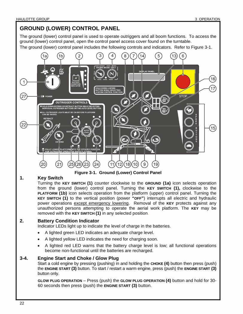
The ground (lower) control panel is used to operate outriggers and all boom functions. To access the ground (lower) control panel, open the control panel access cover found on the turntable. The ground (lower) control panel includes the following controls and indicators. Refer to Figure 3-1.
Figure 3-1. Ground (Lower) Control Panel 1. Key Switch
Turning the KEY SWITCH (1) counter clockwise to the GROUND (1a) icon selects operation from the ground (lower) control panel. Turning the KEY SWITCH (1), clockwise to the
PLATFORM (1b) icon selects operation from the platform (upper) control panel. Turning the KEY SWITCH (1) to the vertical position (power “OFF”) interrupts all electric and hydraulic power operations except emergency lowering. Removal of the KEY protects against any unauthorized persons attempting to operate the aerial work platform. The KEY may be removed with the KEY SWITCH (1) in any selected position.
2. Battery Condition Indicator Indicator LEDs light up to indicate the level of charge in the batteries.
A lighted green LED indicates an adequate charge level.
A lighted yellow LED indicates the need for charging soon.
A lighted red LED warns that the battery charge level is low; all functional operations become non-functional until the batteries are recharged.
3-4. Engine Start and Choke / Glow Plug Start a cold engine by pressing (pushing) in and holding the CHOKE (4) button then press (push) the ENGINE START (3) button. To start / restart a warm engine, press (push) the ENGINE START (3) button only.
GLOW PLUG OPERATION – Press (push) the GLOW PLUG OPERATION (4) button and hold for 30-60 seconds then press (push) the ENGINE START (3) button.
HAULOTTE GROUP 3 OPERATION
23
GROUND (LOWER) CONTROL PANEL (CONTINUED)
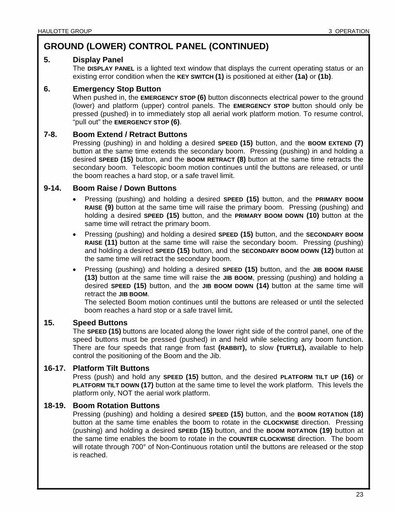
5. Display Panel The DISPLAY PANEL is a lighted text window that displays the current operating status or an existing error condition when the KEY SWITCH (1) is positioned at either (1a) or (1b).
6. Emergency Stop Button When pushed in, the EMERGENCY STOP (6) button disconnects electrical power to the ground (lower) and platform (upper) control panels. The EMERGENCY STOP button should only be pressed (pushed) in to immediately stop all aerial work platform motion. To resume control, “pull out” the EMERGENCY STOP (6).
7-8. Boom Extend / Retract Buttons Pressing (pushing) in and holding a desired SPEED (15) button, and the BOOM EXTEND (7) button at the same time extends the secondary boom. Pressing (pushing) in and holding a desired SPEED (15) button, and the BOOM RETRACT (8) button at the same time retracts the secondary boom. Telescopic boom motion continues until the buttons are released, or until the boom reaches a hard stop, or a safe travel limit.
9-14. Boom Raise / Down Buttons Pressing (pushing) and holding a desired SPEED (15) button, and the PRIMARY BOOM
RAISE (9) button at the same time will raise the primary boom. Pressing (pushing) and holding a desired SPEED (15) button, and the PRIMARY BOOM DOWN (10) button at the same time will retract the primary boom.
Pressing (pushing) and holding a desired SPEED (15) button, and the SECONDARY BOOM
RAISE (11) button at the same time will raise the secondary boom. Pressing (pushing) and holding a desired SPEED (15) button, and the SECONDARY BOOM DOWN (12) button at the same time will retract the secondary boom.
Pressing (pushing) and holding a desired SPEED (15) button, and the JIB BOOM RAISE (13) button at the same time will raise the JIB BOOM, pressing (pushing) and holding a desired SPEED (15) button, and the JIB BOOM DOWN (14) button at the same time will retract the JIB BOOM. The selected Boom motion continues until the buttons are released or until the selected boom reaches a hard stop or a safe travel limit.
15. Speed Buttons The SPEED (15) buttons are located along the lower right side of the control panel, one of the speed buttons must be pressed (pushed) in and held while selecting any boom function. There are four speeds that range from fast (RABBIT), to slow (TURTLE), available to help control the positioning of the Boom and the Jib.
16-17. Platform Tilt Buttons Press (push) and hold any SPEED (15) button, and the desired PLATFORM TILT UP (16) or PLATFORM TILT DOWN (17) button at the same time to level the work platform. This levels the platform only, NOT the aerial work platform.
18-19. Boom Rotation Buttons Pressing (pushing) and holding a desired SPEED (15) button, and the BOOM ROTATION (18) button at the same time enables the boom to rotate in the CLOCKWISE direction. Pressing (pushing) and holding a desired SPEED (15) button, and the BOOM ROTATION (19) button at the same time enables the boom to rotate in the COUNTER CLOCKWISE direction. The boom will rotate through 700° of Non-Continuous rotation until the buttons are released or the stop is reached.
HAULOTTE GROUP 3 OPERATION
24
GROUND (LOWER) CONTROL PANEL (CONTINUED)
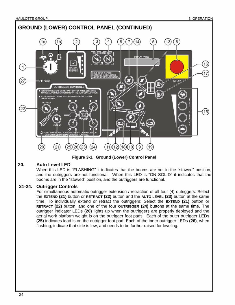
Figure 3-1. Ground (Lower) Control Panel
20. Auto Level LED When this LED is “FLASHING” it indicates that the booms are not in the “stowed” position, and the outriggers are not functional. When this LED is “ON SOLID” it indicates that the booms are in the “stowed” position, and the outriggers are functional.
21-24. Outrigger Controls For simultaneous automatic outrigger extension / retraction of all four (4) outriggers: Select the EXTEND (21) button or RETRACT (22) button and the AUTO LEVEL (23) button at the same time. To individually extend or retract the outriggers: Select the EXTEND (21) button or RETRACT (22) button, and one of the four OUTRIGGER (24) buttons at the same time. The outrigger indicator LEDs (20) lights up when the outriggers are properly deployed and the aerial work platform weight is on the outrigger foot pads. Each of the outer outrigger LEDs (25) indicates load is on the outrigger foot pad. Each of the inner outrigger LEDs (26), when flashing, indicate that side is low, and needs to be further raised for leveling.
HAULOTTE GROUP 3 OPERATION
25
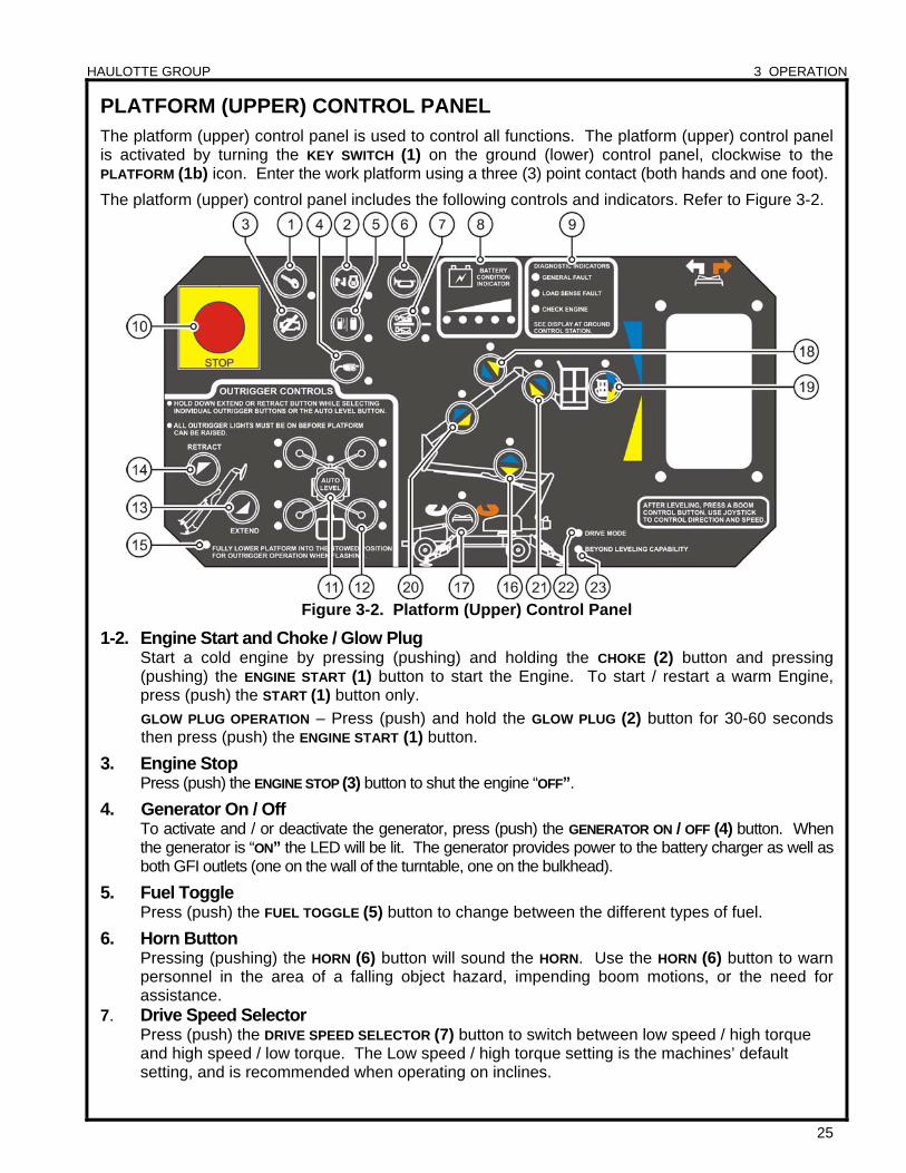
PLATFORM (UPPER) CONTROL PANEL The platform (upper) control panel is used to control all functions. The platform (upper) control panel is activated by turning the KEY SWITCH (1) on the ground (lower) control panel, clockwise to the PLATFORM (1b) icon. Enter the work platform using a three (3) point contact (both hands and one foot).
The platform (upper) control panel includes the following controls and indicators. Refer to Figure 3-2.
Figure 3-2. Platform (Upper) Control Panel
1-2. Engine Start and Choke / Glow Plug Start a cold engine by pressing (pushing) and holding the CHOKE (2) button and pressing (pushing) the ENGINE START (1) button to start the Engine. To start / restart a warm Engine, press (push) the START (1) button only.
GLOW PLUG OPERATION – Press (push) and hold the GLOW PLUG (2) button for 30-60 seconds then press (push) the ENGINE START (1) button.
3. Engine Stop Press (push) the ENGINE STOP (3) button to shut the engine “OFF”.
4. Generator On / Off To activate and / or deactivate the generator, press (push) the GENERATOR ON / OFF (4) button. When the generator is “ON” the LED will be lit. The generator provides power to the battery charger as well as both GFI outlets (one on the wall of the turntable, one on the bulkhead).
5. Fuel Toggle Press (push) the FUEL TOGGLE (5) button to change between the different types of fuel.
6. Horn Button Pressing (pushing) the HORN (6) button will sound the HORN. Use the HORN (6) button to warn personnel in the area of a falling object hazard, impending boom motions, or the need for assistance.
7. Drive Speed Selector Press (push) the DRIVE SPEED SELECTOR (7) button to switch between low speed / high torque and high speed / low torque. The Low speed / high torque setting is the machines’ default setting, and is recommended when operating on inclines.
HAULOTTE GROUP 3 OPERATION
26
PLATFORM (UPPER) CONTROL PANEL (CONTINUED)
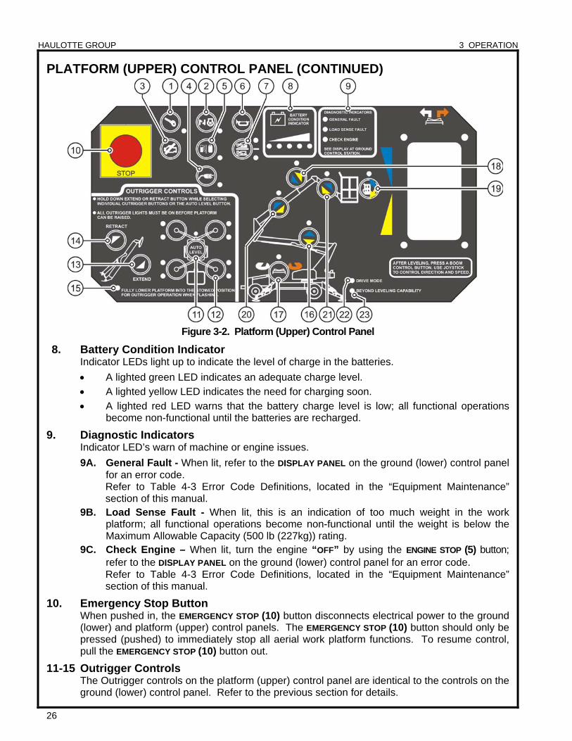
Figure 3-2. Platform (Upper) Control Panel
8. Battery Condition Indicator Indicator LEDs light up to indicate the level of charge in the batteries.
A lighted green LED indicates an adequate charge level.
A lighted yellow LED indicates the need for charging soon.
A lighted red LED warns that the battery charge level is low; all functional operations become non-functional until the batteries are recharged.
9. Diagnostic Indicators Indicator LED’s warn of machine or engine issues.
9A. General Fault - When lit, refer to the DISPLAY PANEL on the ground (lower) control panel for an error code.
Refer to Table 4-3 Error Code Definitions, located in the “Equipment Maintenance” section of this manual.
9B. Load Sense Fault - When lit, this is an indication of too much weight in the work platform; all functional operations become non-functional until the weight is below the Maximum Allowable Capacity (500 lb (227kg)) rating.
9C. Check Engine – When lit, turn the engine “OFF” by using the ENGINE STOP (5) button; refer to the DISPLAY PANEL on the ground (lower) control panel for an error code.
Refer to Table 4-3 Error Code Definitions, located in the “Equipment Maintenance” section of this manual.
10. Emergency Stop Button When pushed in, the EMERGENCY STOP (10) button disconnects electrical power to the ground (lower) and platform (upper) control panels. The EMERGENCY STOP (10) button should only be pressed (pushed) to immediately stop all aerial work platform functions. To resume control, pull the EMERGENCY STOP (10) button out.
11-15 Outrigger Controls The Outrigger controls on the platform (upper) control panel are identical to the controls on the ground (lower) control panel. Refer to the previous section for details.
HAULOTTE GROUP 3 OPERATION
27
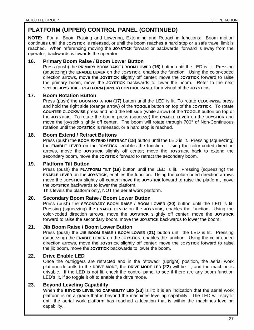
PLATFORM (UPPER) CONTROL PANEL (CONTINUED) NOTE: For all Boom Raising and Lowering, Extending and Retracting functions: Boom motion continues until the JOYSTICK is released, or until the boom reaches a hard stop or a safe travel limit is reached. When referencing moving the JOYSTICK forward or backwards, forward is away from the operator, backwards is towards the operator.
16. Primary Boom Raise / Boom Lower Button Press (push) the PRIMARY BOOM RAISE / BOOM LOWER (16) button until the LED is lit. Pressing (squeezing) the ENABLE LEVER on the JOYSTICK, enables the function. Using the color-coded direction arrows, move the JOYSTICK slightly off center; move the JOYSTICK forward to raise the primary boom, move the JOYSTICK backwards to lower the boom. Refer to the next section JOYSTICK – PLATFORM (UPPER) CONTROL PANEL for a visual of the JOYSTICK.
17. Boom Rotation Button Press (push) the BOOM ROTATION (17) button until the LED is lit. To rotate CLOCKWISE press and hold the right side (orange arrow) of the TOGGLE button on top of the JOYSTICK. To rotate COUNTER CLOCKWISE press and hold the left side (white arrow) of the TOGGLE button on top of the JOYSTICK. To rotate the boom, press (squeeze) the ENABLE LEVER on the JOYSTICK and move the joystick slightly off center. The boom will rotate through 700° of Non-Continuous rotation until the JOYSTICK is released, or a hard stop is reached.
18. Boom Extend / Retract Buttons Press (push) the BOOM EXTEND / RETRACT (18) button until the LED is lit. Pressing (squeezing) the ENABLE LEVER on the JOYSTICK, enables the function. Using the color-coded direction arrows, move the JOYSTICK slightly off center; move the JOYSTICK back to extend the secondary boom, move the JOYSTICK forward to retract the secondary boom.
19. Platform Tilt Button Press (push) the PLATFORM TILT (19) button until the LED is lit. Pressing (squeezing) the ENABLE LEVER on the JOYSTICK, enables the function. Using the color-coded direction arrows move the JOYSTICK slightly off center; move the JOYSTICK forward to raise the platform, move the JOYSTICK backwards to lower the platform. This levels the platform only, NOT the aerial work platform.
20. Secondary Boom Raise / Boom Lower Button Press (push) the SECONDARY BOOM RAISE / BOOM LOWER (20) button until the LED is lit. Pressing (squeezing) the ENABLE LEVER on the JOYSTICK, enables the function. Using the color-coded direction arrows, move the JOYSTICK slightly off center; move the JOYSTICK forward to raise the secondary boom, move the JOYSTICK backwards to lower the boom.
21. Jib Boom Raise / Boom Lower Button Press (push) the JIB BOOM RAISE / BOOM LOWER (21) button until the LED is lit. Pressing (squeezing) the ENABLE LEVER on the JOYSTICK, enables the function. Using the color-coded direction arrows, move the JOYSTICK slightly off center; move the JOYSTICK forward to raise the jib boom, move the JOYSTICK backwards to lower the boom.
22. Drive Enable LED Once the outriggers are retracted and in the “stowed” (upright) position, the aerial work platform defaults to the DRIVE MODE, the DRIVE MODE LED (22) will be lit, and the machine is drivable. If the LED is not lit, check the control panel to see if there are any boom function LED’s lit, if so toggle it off to enable the drive mode.
23. Beyond Leveling Capability When the BEYOND LEVELING CAPABILITY LED (23) is lit; it is an indication that the aerial work platform is on a grade that is beyond the machines leveling capability. The LED will stay lit until the aerial work platform has reached a location that is within the machines leveling capability.
HAULOTTE GROUP 3 OPERATION
28
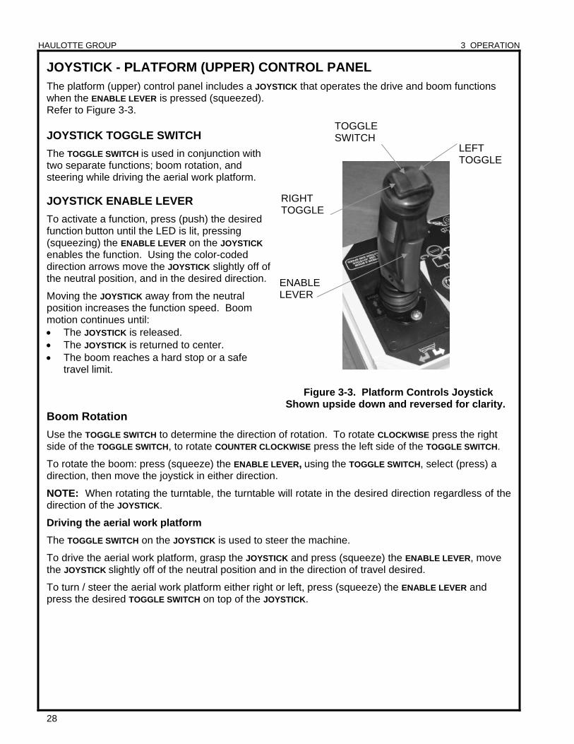
JOYSTICK - PLATFORM (UPPER) CONTROL PANEL The platform (upper) control panel includes a JOYSTICK that operates the drive and boom functions when the ENABLE LEVER is pressed (squeezed). Refer to Figure 3-3. JOYSTICK TOGGLE SWITCH
The TOGGLE SWITCH is used in conjunction with two separate functions; boom rotation, and steering while driving the aerial work platform.
JOYSTICK ENABLE LEVER
To activate a function, press (push) the desired function button until the LED is lit, pressing (squeezing) the ENABLE LEVER on the JOYSTICK enables the function. Using the color-coded direction arrows move the JOYSTICK slightly off of the neutral position, and in the desired direction.
Moving the JOYSTICK away from the neutral position increases the function speed. Boom motion continues until: The JOYSTICK is released. The JOYSTICK is returned to center. The boom reaches a hard stop or a safe
travel limit.
Figure 3-3. Platform Controls Joystick Shown upside down and reversed for clarity.
Boom Rotation
Use the TOGGLE SWITCH to determine the direction of rotation. To rotate CLOCKWISE press the right side of the TOGGLE SWITCH, to rotate COUNTER CLOCKWISE press the left side of the TOGGLE SWITCH.
To rotate the boom: press (squeeze) the ENABLE LEVER, using the TOGGLE SWITCH, select (press) a direction, then move the joystick in either direction.
NOTE: When rotating the turntable, the turntable will rotate in the desired direction regardless of the direction of the JOYSTICK.
Driving the aerial work platform
The TOGGLE SWITCH on the JOYSTICK is used to steer the machine.
To drive the aerial work platform, grasp the JOYSTICK and press (squeeze) the ENABLE LEVER, move the JOYSTICK slightly off of the neutral position and in the direction of travel desired.
To turn / steer the aerial work platform either right or left, press (squeeze) the ENABLE LEVER and press the desired TOGGLE SWITCH on top of the JOYSTICK.
LEFT TOGGLE
RIGHT TOGGLE
ENABLELEVER
TOGGLESWITCH
HAULOTTE GROUP 3 OPERATION
29
NORMAL OPERATING PROCEDURE
Become familiar with the location and function of all controls. Learn to smoothly START and STOP all boom functions.
Perform the following procedures to operate the machine:
Read and obey all safety precautions and operating instructions, as well as all Federal, State, and Local codes and regulations.
Conduct a Pre-Operation Inspection by performing all recommended Daily Service Checks. Refer to the “Equipment Maintenance” Section of this manual.
Position the aerial work platform at the work area. Make sure the aerial work platform is on a firm and level surface and there are no potential hazards such as overhead obstructions or electrically charged conductors. DO NOT operate the aerial work platform if such hazards exist.
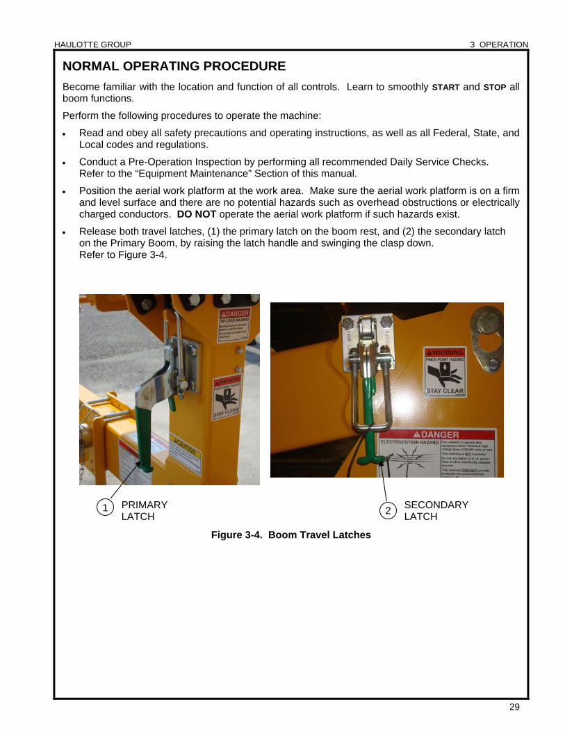
Release both travel latches, (1) the primary latch on the boom rest, and (2) the secondary latch on the Primary Boom, by raising the latch handle and swinging the clasp down. Refer to Figure 3-4.
Figure 3-4. Boom Travel Latches
1 2PRIMARY LATCH
SECONDARY LATCH
HAULOTTE GROUP 3 OPERATION
30
NORMAL OPERATING PROCEDURE (CONTINUED)
Become familiar with the location and function of all controls. Learn to smoothly START and STOP all boom functions. At the ground (lower) control panel, turn the KEY SWITCH (1) counter clockwise to the GROUND
CONTROLS (1a) icon. If power does not come on, make sure that both of the EMERGENCY STOP buttons; GROUND (6), and PLATFORM (5), are pulled out and the main power disconnect plug is plugged in.
The control microprocessor will perform self-diagnostics to test the operating system. After several seconds, the DISPLAY PANEL window will read:
HAULOTTE GROUP ACCESS SOLUTIONS
Monitor the battery condition indicator during operation and charge the batteries as necessary.
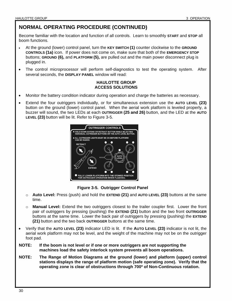
Extend the four outriggers individually, or for simultaneous extension use the AUTO LEVEL (23) button on the ground (lower) control panel. When the aerial work platform is leveled properly, a buzzer will sound, the two LEDs at each OUTRIGGER (25 and 26) button, and the LED at the AUTO
LEVEL (23) button will be lit. Refer to Figure 3-5.
Figure 3-5. Outrigger Control Panel
o Auto Level: Press (push) and hold the EXTEND (21) and AUTO LEVEL (23) buttons at the same time.
o Manual Level: Extend the two outriggers closest to the trailer coupler first. Lower the front pair of outriggers by pressing (pushing) the EXTEND (21) button and the two front OUTRIGGER buttons at the same time. Lower the back pair of outriggers by pressing (pushing) the EXTEND
(21) button and the two back OUTRIGGER buttons at the same time.
Verify that the AUTO LEVEL (23) indicator LED is lit. If the AUTO LEVEL (23) indicator is not lit, the aerial work platform may not be level, and the weight of the machine may not be on the outrigger foot pad.
NOTE: If the boom is not level or if one or more outriggers are not supporting the machines load the safety interlock system prevents all boom operations.
NOTE: The Range of Motion Diagrams at the ground (lower) and platform (upper) control stations displays the range of platform motion (safe operating zone). Verify that the operating zone is clear of obstructions through 700º of Non-Continuous rotation.
HAULOTTE GROUP 3 OPERATION
31
NORMAL OPERATING PROCEDURE (CONTINUED)
Use the ground (lower) control panel to operate the boom lift functions. Raise, lower, extend and rotate the booms by pressing (pushing) and holding the desired SPEED and function buttons at the same time.
Fully lower the boom onto the boom rest to enter the platform using a three (3) point contact (both hands and one foot.
Raise the safety bar and enter the work platform by using a three (3) point contact (both hands and one foot). Put on a safety harness and attach the lanyard to the ANCHORAGE (attachment point) on the side of the platform support beam.
Use the platform (upper) control panel to operate the boom lift functions. Press (push) the desired function button until the LED is lit. Pressing (squeezing) the enable lever on the joystick enables the function. Using the color-coded direction arrows move the joystick slightly off center in the desired direction.
Moving the joystick further off center increases the function speed, moving the joystick back toward the center decreases the function speed. Boom motion continues until: the joystick released, the joystick is returned to center, or until the boom reaches a hard stop or a safe travel limit.
NOTE: When rotating the turntable, press the desired toggle switch, the turntable will rotate in the desired direction regardless of the direction of the joystick.
When all aerial work platform operations are complete, fully retract all boom extensions. Center the boom over the boom rest and fully lower the boom until seated in the “stowed” position for transport.
NOTE: Always fully retract, rotate and lower the boom to the “stowed” position before exiting the platform.
Turn the key switch to the GROUND CONTROL (1a) position.
Unfasten the safety harness and exit the platform by using a three (3) point contact (both hands and one foot).
Engage both travel latches.
NOTE: Refer back to Figure 3-4 for a visual of these latches.
Inspect the area beneath the aerial work platform and trailer for obstructions before retracting outriggers. Press (push) and hold the outrigger RETRACT (22) button and the AUTO LEVEL (23) button until all outriggers are fully retracted to their “stowed” (upright) positions.
NOTE: Safety switches prevent outrigger retraction until the boom is completely lowered and in the “stowed” position.
At the ground (lower) control panel turn the KEY SWITCH (1) to the vertical (power “OFF”) position, and remove the key.
HAULOTTE GROUP 3 OPERATION
32
DRIVE FUNCTION The Drive Function allows the operator to drive the aerial work platform, deploy, retract and level the outriggers from the platform (upper) control panel. The platform (upper) control panel is used to control all functions.
Use the following procedure to operate the Drive Function.
Fully lower all booms into the “stowed” position.
Raise all outriggers into the “stowed” (upright) position.
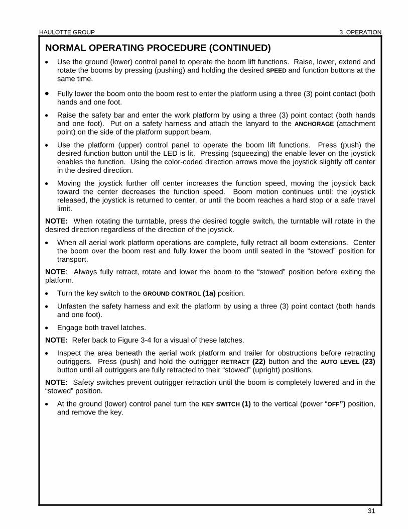
Press (push) the DRIVE SPEED SELECTOR (7) button on the platform (upper) control panel. Refer to Figure 3-6.
Use the JOYSTICK to determine the direction to be driven, use the TOGGLE SWITCH to steer the machine in the desired direction. The aerial work platform will continue to move until the joystick is released, or the joystick is returned to center (neutral) position.
Once the work location is reached, lower the outriggers, and level the aerial work platform using either the ground (lower) or platform (upper) control panel.
Figure 3-6. Drive Speed Selector
NOTE: Boom functions are not available until all outriggers are fully deployed and the aerial work platform is leveled.
MANUAL BRAKE RELEASE
When the aerial work platform is shut down, or is inoperable, the brakes are automatically locked. The brakes need to be released to allow the wheels to roll in order to winch / tow the machine on to a truck bed or trailer.
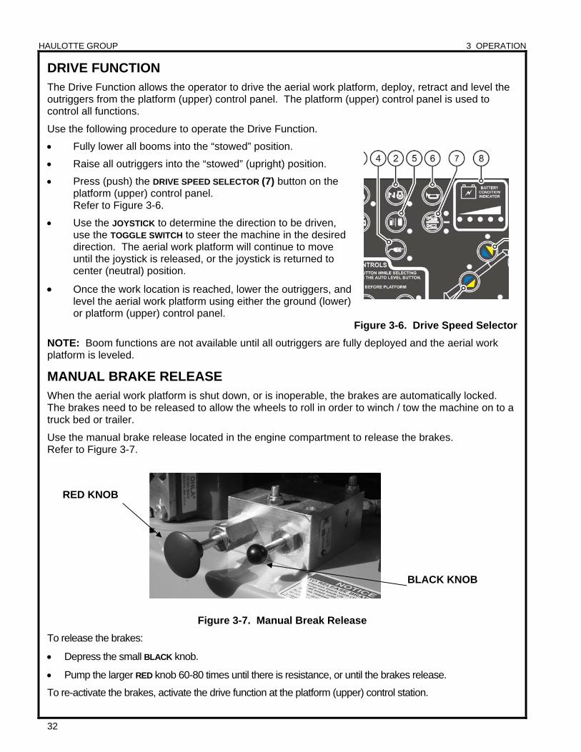
Use the manual brake release located in the engine compartment to release the brakes. Refer to Figure 3-7.
Figure 3-7. Manual Break Release
To release the brakes:
Depress the small BLACK knob.
Pump the larger RED knob 60-80 times until there is resistance, or until the brakes release.
To re-activate the brakes, activate the drive function at the platform (upper) control station.
RED KNOB
BLACK KNOB
HAULOTTE GROUP 3 OPERATION
33
HAND PUMP
PROPORTIONAL VALVE
ROTATION BUTTON
RETRACTBUTTON
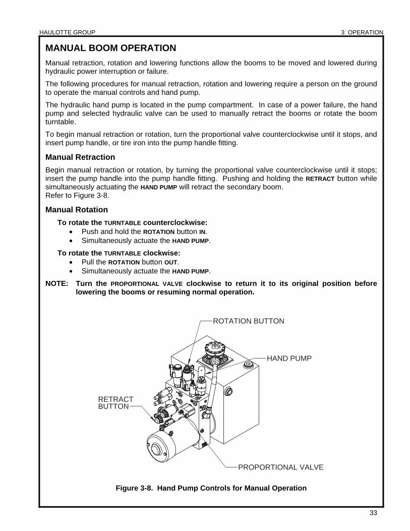
MANUAL BOOM OPERATION
Manual retraction, rotation and lowering functions allow the booms to be moved and lowered during hydraulic power interruption or failure.
The following procedures for manual retraction, rotation and lowering require a person on the ground to operate the manual controls and hand pump.
The hydraulic hand pump is located in the pump compartment. In case of a power failure, the hand pump and selected hydraulic valve can be used to manually retract the booms or rotate the boom turntable.
To begin manual retraction or rotation, turn the proportional valve counterclockwise until it stops, and insert pump handle, or tire iron into the pump handle fitting.
Manual Retraction
Begin manual retraction or rotation, by turning the proportional valve counterclockwise until it stops; insert the pump handle into the pump handle fitting. Pushing and holding the RETRACT button while simultaneously actuating the HAND PUMP will retract the secondary boom. Refer to Figure 3-8.
Manual Rotation
To rotate the TURNTABLE counterclockwise: Push and hold the ROTATION button IN. Simultaneously actuate the HAND PUMP.
To rotate the TURNTABLE clockwise: Pull the ROTATION button OUT. Simultaneously actuate the HAND PUMP.
NOTE: Turn the PROPORTIONAL VALVE clockwise to return it to its original position before lowering the booms or resuming normal operation.
Figure 3-8. Hand Pump Controls for Manual Operation
HAULOTTE GROUP 3 OPERATION
34
BUTTON
LIFT CYLINDERSECONDARY
VALVE "PUSH"
KNUCKLE
JIBLIFT CYLINDER
VALVE "PUSH"
BUTTON BUTTON
LIFT CYLINDERPRIMARY
VALVE "PUSH"
TURNTABLE
PRIMARY LIFT CYLINDER JIB LIFT
CYLINDER
SECONDARYLIFT CYLINDER
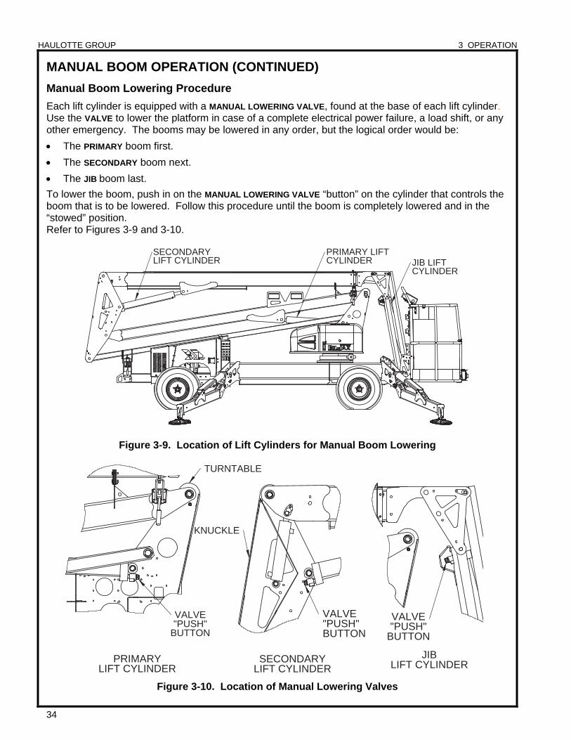
MANUAL BOOM OPERATION (CONTINUED)
Manual Boom Lowering Procedure
Each lift cylinder is equipped with a MANUAL LOWERING VALVE, found at the base of each lift cylinder. Use the VALVE to lower the platform in case of a complete electrical power failure, a load shift, or any other emergency. The booms may be lowered in any order, but the logical order would be:
The PRIMARY boom first.
The SECONDARY boom next.
The JIB boom last.
To lower the boom, push in on the MANUAL LOWERING VALVE “button” on the cylinder that controls the boom that is to be lowered. Follow this procedure until the boom is completely lowered and in the “stowed” position. Refer to Figures 3-9 and 3-10.
Figure 3-9. Location of Lift Cylinders for Manual Boom Lowering
Figure 3-10. Location of Manual Lowering Valves
HAULOTTE GROUP 3 OPERATION
35
LIFTING THE AERIAL WORK PLATFORM
Refer to Figure 3-11.
Completely retract and lower all booms into the “stowed” position.
Secure both boom travel latches (A).
Remove all loose materials from machine.
Retract all outriggers cylinders to fully “stowed” (upright) position.
When using a crane, use only the designated crane (fork lift) pockets (B). Follow all crane operating instructions as indicated by the crane manufacturer.
When using a forklift, use only the designated forklift pockets (B). Follow all forklift operating instructions as indicated by the forklift manufacturer.
Adjust rigging to keep the machine level and to minimize the risk of damage to machine.
NOTE: Only trained and authorized personnel should attempt to lift the aerial work platform.
Figure 3-11. Lifting the Aerial Work Platform
B
A
AB
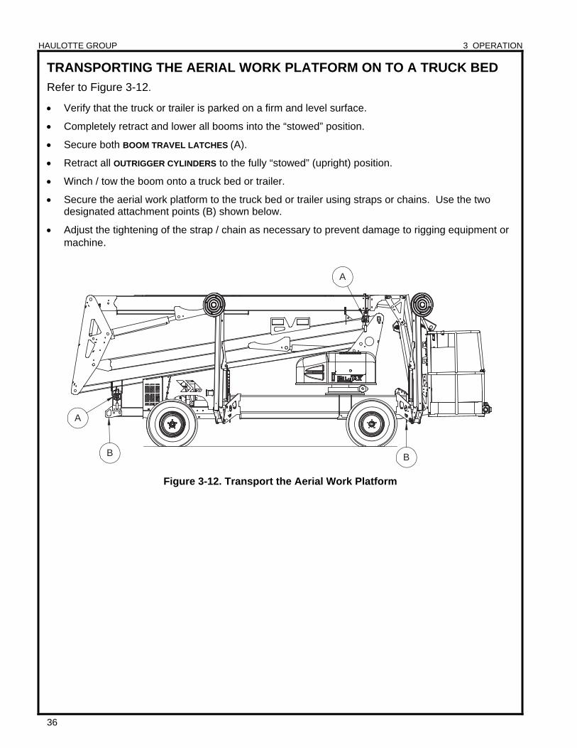
HAULOTTE GROUP 3 OPERATION
36
A
B B
A
TRANSPORTING THE AERIAL WORK PLATFORM ON TO A TRUCK BED
Refer to Figure 3-12.
Verify that the truck or trailer is parked on a firm and level surface.
Completely retract and lower all booms into the “stowed” position.
Secure both BOOM TRAVEL LATCHES (A).
Retract all OUTRIGGER CYLINDERS to the fully “stowed” (upright) position.
Winch / tow the boom onto a truck bed or trailer.
Secure the aerial work platform to the truck bed or trailer using straps or chains. Use the two designated attachment points (B) shown below.
Adjust the tightening of the strap / chain as necessary to prevent damage to rigging equipment or machine.
Figure 3-12. Transport the Aerial Work Platform
HAULOTTE GROUP 4 EQUIPMENT MAINTENANCE
37
4 EQUIPMENT MAINTENANCE
Performing the appropriate maintenance procedures will extend the life of the aerial work platform and will help ensure the safety of personnel operating the equipment.
Repair, replacement or adjustment of any hydraulic or electrical control device should be performed only by fully trained and authorized personnel. These include, but are not limited to, hydraulic load valves, hydraulic flow control valves, solenoid valves, and limit switches. These are safety related controls. Improper adjustment or tampering with these devices may impair aerial work platform function and result in safety or damage hazards.
Persons performing maintenance or repairs on the aerial work platform should be trained in accordance with the manufacturer’s recommendations. Contact Haulotte Group Customer Service Department: at 1-800-537-0540 or visit Haulotte Group online at www.haulotte-usa.com if additional information is needed.
Critical or suspect areas identified during any scheduled inspection of the aerial work platform shall be examined by qualified personnel in accordance with all Federal, State, and Local codes and regulations.
NEVER operate the aerial work platform if a defect or malfunction is identified or suspected. All defects and malfunctions must be repaired, and all maintenance performed, before returning an aerial work platform to service.
This manual contains a list of recommended maintenance procedures to be performed daily, weekly, monthly, and annually. Refer to it when inspecting this machine.
It is the practice of Haulotte Group to issue Service and / or Safety Bulletins, which may include updates to the information contained in this manual. In such instances, procedures contained in Haulotte Group Service Bulletins or Safety Bulletins supersede the information contained in manual.
ALWAYS follow the maintenance schedule, regardless of use.

HAULOTTE GROUP 4 EQUIPMENT MAINTENANCE
38
CHARGING
80% CHARGED
CHECK BATTERY
Linear Battery Charger
CHARGE CURRENT
PUSH
FOR
BATTERY VOLTAGE
FUSE 15A
SLO BLO
BATTERY RECHARGE Recharge aerial work platform batteries after each 8-hour work shift or as needed. When using the gas engine, press (push) the GENERATOR (4) button on the platform (upper) control panel to charge the batteries. When the aerial work platform is not in use, batteries should be recharged at least once per week. Under normal circumstances, battery recharge should take approximately 10-12 hours. However, a full recharge may take up to 24 hours, if the battery charge is extremely low.
To recharge the aerial work platform batteries:
Move the aerial work platform to a well-ventilated area with direct access to an AC electrical outlet. Keep the aerial work platform and batteries away from open flame or other potential ignition sources.
Attach a 12 AWG multi-strand, grounded EXTENSION CORD with a maximum length of 50 feet (15 meters) to the receptacle located inside the ENGINE COMPARTMENT. The generator may need to be disconnected from the receptacle prior to connecting the extension cord.
NOTE: Using an underrated or long power cord will reduce the output of the battery charger and may extend charge time.
Plug the EXTENSION CORD into outlet. Verify that the GREEN CHARGING indicator LED is lit on the BATTERY CHARGER FACEPLATE. Refer to Figure 4-1.
The charging indicator LED remains lit continuously during the first stage of the charge cycle. The charge current will be displayed on the BATTERY CHARGER FACEPLATE.
To display the Battery Voltage, press (push) in and hold the BATTERY VOLTAGE button. Refer to Figure 4-1.
Figure 4-1. Battery Charger Faceplate
WARNING Recharge batteries in a well-ventilated area only. DO NOT charge batteries near fire, spark or other potential ignition sources. Batteries may emit highly explosive Hydrogen gas while charging. Failure to properly ventilate the charge gasses could result in death or serious injury. Always charge aerial work platform batteries away from flammable materials.
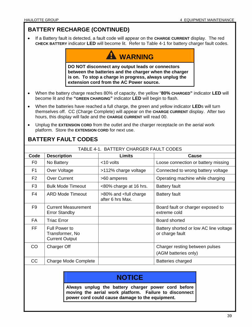
HAULOTTE GROUP 4 EQUIPMENT MAINTENANCE
39
BATTERY RECHARGE (CONTINUED)
If a Battery fault is detected, a fault code will appear on the CHARGE CURRENT display. The red CHECK BATTERY indicator LED will become lit. Refer to Table 4-1 for battery charger fault codes.
When the battery charge reaches 80% of capacity, the yellow “80% CHARGED” indicator LED will become lit and the “GREEN CHARGING” indicator LED will begin to flash.
When the batteries have reached a full charge, the green and yellow indicator LEDs will turn themselves off. CC (Charge Complete) will appear on the CHARGE CURRENT display. After two hours, this display will fade and the CHARGE CURRENT will read 00.
Unplug the EXTENSION CORD from the outlet and the charger receptacle on the aerial work platform. Store the EXTENSION CORD for next use.
BATTERY FAULT CODES
TABLE 4-1. BATTERY CHARGER FAULT CODES
Code Description Limits Cause
F0 No Battery <10 volts Loose connection or battery missing
F1 Over Voltage >112% charge voltage Connected to wrong battery voltage
F2 Over Current >60 amperes Operating machine while charging
F3 Bulk Mode Timeout <80% charge at 16 hrs. Battery fault
F4 ARD Mode Timeout >80% and <full charge after 6 hrs Max.
Battery fault
F9 Current Measurement Error Standby
Board fault or charger exposed to extreme cold
FA Triac Error Board shorted
FF Full Power to Transformer, No Current Output
Battery shorted or low AC line voltage or charge fault
CO Charger Off Charger resting between pulses
(AGM batteries only)
CC Charge Mode Complete Batteries charged
WARNING DO NOT disconnect any output leads or connectors between the batteries and the charger when the charger is on. To stop a charge in progress, always unplug the extension cord from the AC Power source.
NOTICE Always unplug the battery charger power cord before moving the aerial work platform. Failure to disconnect power cord could cause damage to the equipment.
HAULOTTE GROUP 4 EQUIPMENT MAINTENANCE
40
DAILY SERVICE CHECKS The following Maintenance Procedures should be performed daily or before each operation:
Verify that all decals are legible, correctly applied, and in plain view. Refer to the “Decal Replacement” section of this manual for decal locations.
Verify that all controls and indicators at the ground (lower) and platform (upper) control stations operate properly.
Lower outriggers to level the aerial work platform.
Operate all boom functions, including all jib functions.
Press (push) the EMERGENCY STOP button. Verify that all functions are deactivated.
Verify that the cylinders are functional and there is no internal leakage, an indication of this is that the booms would not remain elevated, and / or they may drift.
Pull out the EMERGENCY STOP button, all functions will now be activated. Lower the booms.
If either control panel is unresponsive, refer to the Trouble Shooting procedures. TABLE 4-2 TROUBLESHOOTING is located later in this section.
If the GROUND (LOWER) CONTROL DISPLAY PANEL displays an error code, refer to the Control Panel Error Code definitions. TABLE 4-3 ERROR CODE DEFINITIONS is located later in this section.
If the MOTOR CONTROLLER’S green light is flashing there is an error, refer to the Motor Controller Error Code Definitions. TABLE 4-4 ERROR CODE DEFINITIONS – MOTOR CONTROLLER, is located later in this section.
If the aerial work platform has the Drive and Set option, operate the drive function from the platform (upper) control panel.
Verify correct operation of turn signals, brakes and running lights.
Verify proper tire inflation. See the side wall of the tire for proper inflation.
Inspect tires for damage or loose or missing lug nuts.
Repair or replace as necessary.
Inspect structural components and platform for obvious damage or debris.
Repair or replace as necessary.
Inspect the aerial work platform for missing, loose or damaged fasteners, including pins and bolts.
Verify that the boom / jib limit switches operate correctly.
Limit switches are actuated when the primary, secondary and jib booms are in the fully lowered “stowed” position. Limit switches must be activated to raise or lower outriggers.
If outrigger controls are unresponsive when the booms are fully lowered and “stowed”, inspect the limit switches for loose mounting or visible damage.
Repair or replace as necessary.
Check engine oil level.
Add oil as necessary. Manufacturer recommends engine oil type 5W-30.
Check engine fuel level.
Add fuel as necessary.
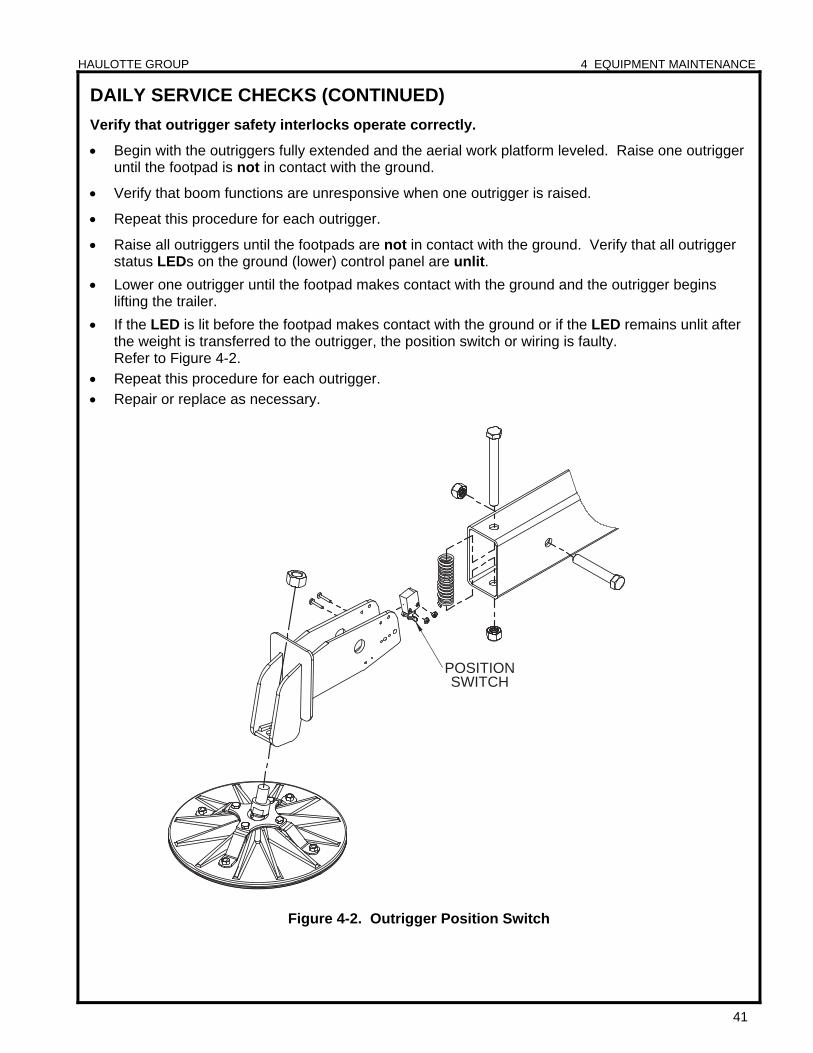
HAULOTTE GROUP 4 EQUIPMENT MAINTENANCE
41
POSITIONSWITCH
DAILY SERVICE CHECKS (CONTINUED)
Verify that outrigger safety interlocks operate correctly.
Begin with the outriggers fully extended and the aerial work platform leveled. Raise one outrigger until the footpad is not in contact with the ground.
Verify that boom functions are unresponsive when one outrigger is raised.
Repeat this procedure for each outrigger.
Raise all outriggers until the footpads are not in contact with the ground. Verify that all outrigger status LEDs on the ground (lower) control panel are unlit.
Lower one outrigger until the footpad makes contact with the ground and the outrigger begins lifting the trailer.
If the LED is lit before the footpad makes contact with the ground or if the LED remains unlit after the weight is transferred to the outrigger, the position switch or wiring is faulty. Refer to Figure 4-2.
Repeat this procedure for each outrigger.
Repair or replace as necessary.
Figure 4-2. Outrigger Position Switch
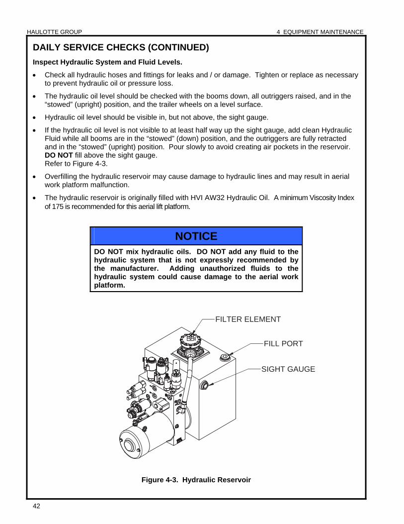
HAULOTTE GROUP 4 EQUIPMENT MAINTENANCE
42
SIGHT GAUGE
FILL PORT
FILTER ELEMENT
DAILY SERVICE CHECKS (CONTINUED)
Inspect Hydraulic System and Fluid Levels.
Check all hydraulic hoses and fittings for leaks and / or damage. Tighten or replace as necessary to prevent hydraulic oil or pressure loss.
The hydraulic oil level should be checked with the booms down, all outriggers raised, and in the “stowed” (upright) position, and the trailer wheels on a level surface.
Hydraulic oil level should be visible in, but not above, the sight gauge.
If the hydraulic oil level is not visible to at least half way up the sight gauge, add clean Hydraulic Fluid while all booms are in the “stowed” (down) position, and the outriggers are fully retracted and in the “stowed” (upright) position. Pour slowly to avoid creating air pockets in the reservoir. DO NOT fill above the sight gauge. Refer to Figure 4-3.
Overfilling the hydraulic reservoir may cause damage to hydraulic lines and may result in aerial work platform malfunction.
The hydraulic reservoir is originally filled with HVI AW32 Hydraulic Oil. A minimum Viscosity Index of 175 is recommended for this aerial lift platform.
Figure 4-3. Hydraulic Reservoir
NOTICE DO NOT mix hydraulic oils. DO NOT add any fluid to the hydraulic system that is not expressly recommended by the manufacturer. Adding unauthorized fluids to the hydraulic system could cause damage to the aerial work platform.
HAULOTTE GROUP 4 EQUIPMENT MAINTENANCE
43
WEEKLY SERVICE CHECKS Perform the following service checks at least once each week in addition to all recommended Daily Service Checks:
Check Battery Electrolyte level.
If battery charge is low, add enough water to bring the electrolyte level to the top of the plates.
If batteries are fully charged, raise electrolyte level to full mark in each cell.
Inspect all electrical wiring.
Check for cuts, loose terminals, broken wires, chaffing and corrosion.
Repair all damage, remove corrosion and seal with proper materials.
Inspect the aerial work platform for missing, loose or damaged hardware.
Repair or replace as necessary.
Inspect all hydraulic system components including pump and motor and cylinders for damage, leaks, loss of pressure or speed, and unusual noise or vibration.
Repair or replace as necessary.
Inspect Jib Bushings for damage.
Check the Jib Bushings, the bushings should not spin or separate from the retaining bore.
Replace annually, or more frequently as necessary.
Inspect telescoping boom section for missing or damaged Wear Pads.
Check Wear Pads for loose or missing hardware.
Repair or replace as necessary.
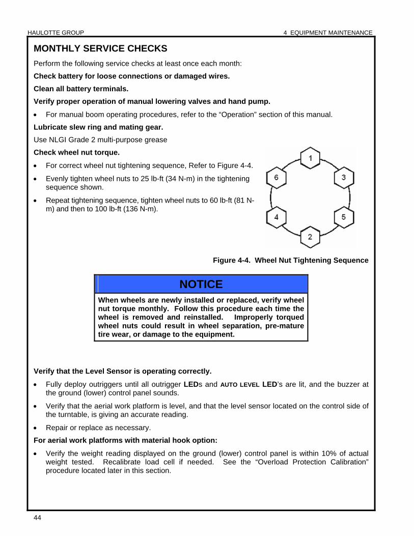
HAULOTTE GROUP 4 EQUIPMENT MAINTENANCE
44
MONTHLY SERVICE CHECKS
Perform the following service checks at least once each month:
Check battery for loose connections or damaged wires.
Clean all battery terminals.
Verify proper operation of manual lowering valves and hand pump.
For manual boom operating procedures, refer to the “Operation” section of this manual.
Lubricate slew ring and mating gear.
Use NLGI Grade 2 multi-purpose grease
Check wheel nut torque.
For correct wheel nut tightening sequence, Refer to Figure 4-4.
Evenly tighten wheel nuts to 25 lb-ft (34 N-m) in the tightening sequence shown.
Repeat tightening sequence, tighten wheel nuts to 60 lb-ft (81 N-m) and then to 100 lb-ft (136 N-m).
Figure 4-4. Wheel Nut Tightening Sequence
Verify that the Level Sensor is operating correctly.
Fully deploy outriggers until all outrigger LEDs and AUTO LEVEL LED’s are lit, and the buzzer at the ground (lower) control panel sounds.
Verify that the aerial work platform is level, and that the level sensor located on the control side of the turntable, is giving an accurate reading.
Repair or replace as necessary.
For aerial work platforms with material hook option:
Verify the weight reading displayed on the ground (lower) control panel is within 10% of actual weight tested. Recalibrate load cell if needed. See the “Overload Protection Calibration” procedure located later in this section.
NOTICE When wheels are newly installed or replaced, verify wheel nut torque monthly. Follow this procedure each time the wheel is removed and reinstalled. Improperly torqued wheel nuts could result in wheel separation, pre-mature tire wear, or damage to the equipment.
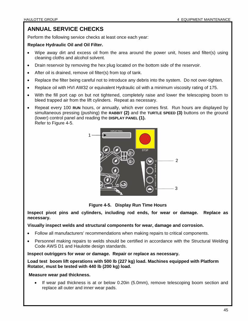
HAULOTTE GROUP 4 EQUIPMENT MAINTENANCE
45
ANNUAL SERVICE CHECKS Perform the following service checks at least once each year:
Replace Hydraulic Oil and Oil Filter.
Wipe away dirt and excess oil from the area around the power unit, hoses and filter(s) using cleaning cloths and alcohol solvent.
Drain reservoir by removing the hex plug located on the bottom side of the reservoir.
After oil is drained, remove oil filter(s) from top of tank.
Replace the filter being careful not to introduce any debris into the system. Do not over-tighten.
Replace oil with HVI AW32 or equivalent Hydraulic oil with a minimum viscosity rating of 175.
With the fill port cap on but not tightened, completely raise and lower the telescoping boom to bleed trapped air from the lift cylinders. Repeat as necessary.
Repeat every 100 RUN hours, or annually, which ever comes first. Run hours are displayed by simultaneous pressing (pushing) the RABBIT (2) and the TURTLE SPEED (3) buttons on the ground (lower) control panel and reading the DISPLAY PANEL (1). Refer to Figure 4-5.
Figure 4-5. Display Run Time Hours
Inspect pivot pins and cylinders, including rod ends, for wear or damage. Replace as necessary.
Visually inspect welds and structural components for wear, damage and corrosion.
Follow all manufacturers’ recommendations when making repairs to critical components.
Personnel making repairs to welds should be certified in accordance with the Structural Welding Code AWS D1 and Haulotte design standards.
Inspect outriggers for wear or damage. Repair or replace as necessary.
Load test boom lift operations with 500 lb (227 kg) load. Machines equipped with Platform Rotator, must be tested with 440 lb (200 kg) load.
Measure wear pad thickness.
If wear pad thickness is at or below 0.20in (5.0mm), remove telescoping boom section and replace all outer and inner wear pads.
2
1
3
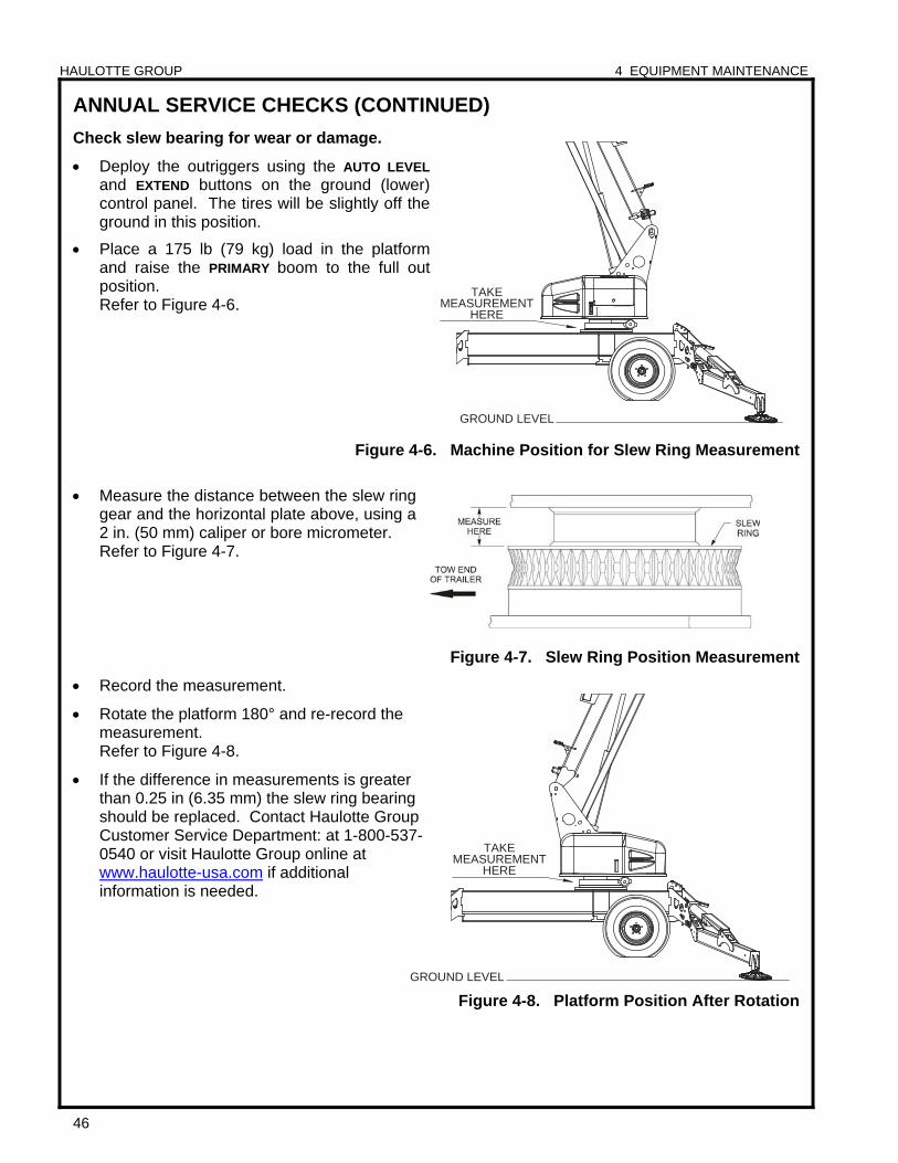
HAULOTTE GROUP 4 EQUIPMENT MAINTENANCE
46
ANNUAL SERVICE CHECKS (CONTINUED)
Check slew bearing for wear or damage.
Deploy the outriggers using the AUTO LEVEL
and EXTEND buttons on the ground (lower) control panel. The tires will be slightly off the ground in this position.
Place a 175 lb (79 kg) load in the platform and raise the PRIMARY boom to the full out position. Refer to Figure 4-6.
Figure 4-6. Machine Position for Slew Ring Measurement
Measure the distance between the slew ring gear and the horizontal plate above, using a 2 in. (50 mm) caliper or bore micrometer. Refer to Figure 4-7.
Figure 4-7. Slew Ring Position Measurement
Record the measurement.
Rotate the platform 180° and re-record the measurement. Refer to Figure 4-8.
If the difference in measurements is greater than 0.25 in (6.35 mm) the slew ring bearing should be replaced. Contact Haulotte Group Customer Service Department: at 1-800-537-0540 or visit Haulotte Group online at www.haulotte-usa.com if additional information is needed.
Figure 4-8. Platform Position After Rotation
GROUND LEVEL
TAKEMEASUREMENT
HERE
GROUND LEVEL
TAKEMEASUREMENT
HERE
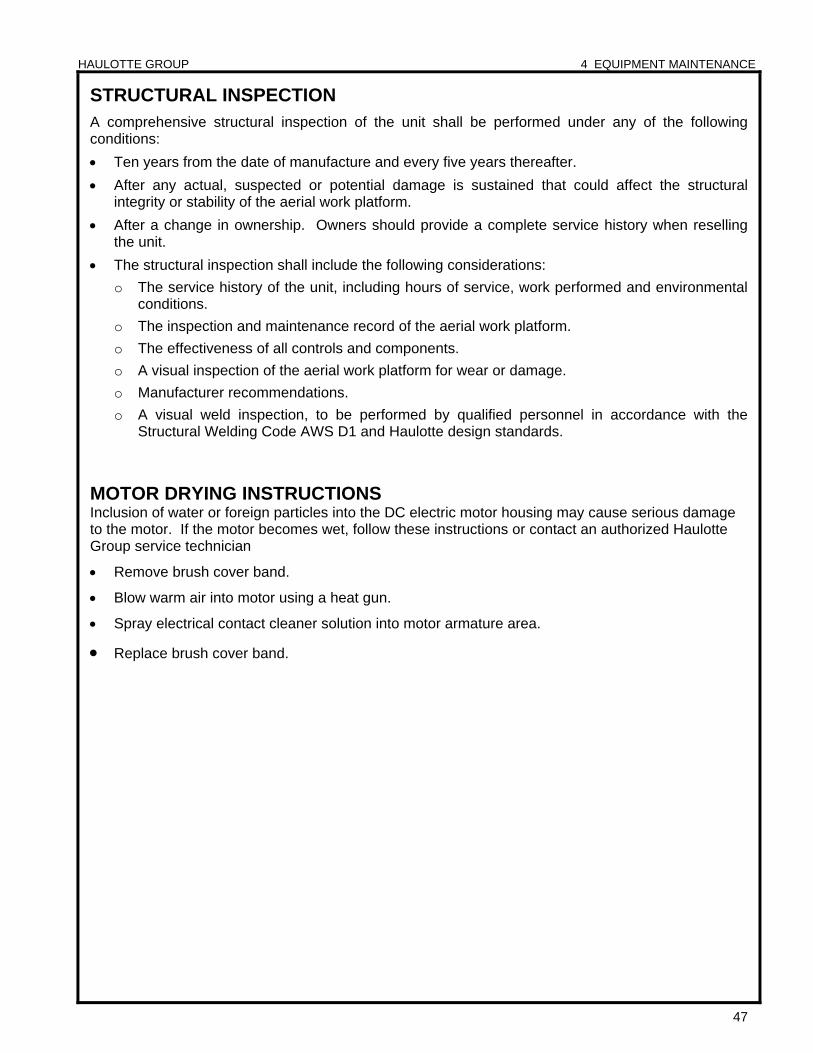
HAULOTTE GROUP 4 EQUIPMENT MAINTENANCE
47
STRUCTURAL INSPECTION A comprehensive structural inspection of the unit shall be performed under any of the following conditions:
Ten years from the date of manufacture and every five years thereafter.
After any actual, suspected or potential damage is sustained that could affect the structural integrity or stability of the aerial work platform.
After a change in ownership. Owners should provide a complete service history when reselling the unit.
The structural inspection shall include the following considerations:
o The service history of the unit, including hours of service, work performed and environmental conditions.
o The inspection and maintenance record of the aerial work platform.
o The effectiveness of all controls and components.
o A visual inspection of the aerial work platform for wear or damage.
o Manufacturer recommendations.
o A visual weld inspection, to be performed by qualified personnel in accordance with the Structural Welding Code AWS D1 and Haulotte design standards.
MOTOR DRYING INSTRUCTIONS Inclusion of water or foreign particles into the DC electric motor housing may cause serious damage to the motor. If the motor becomes wet, follow these instructions or contact an authorized Haulotte Group service technician
Remove brush cover band.
Blow warm air into motor using a heat gun.
Spray electrical contact cleaner solution into motor armature area.
Replace brush cover band.
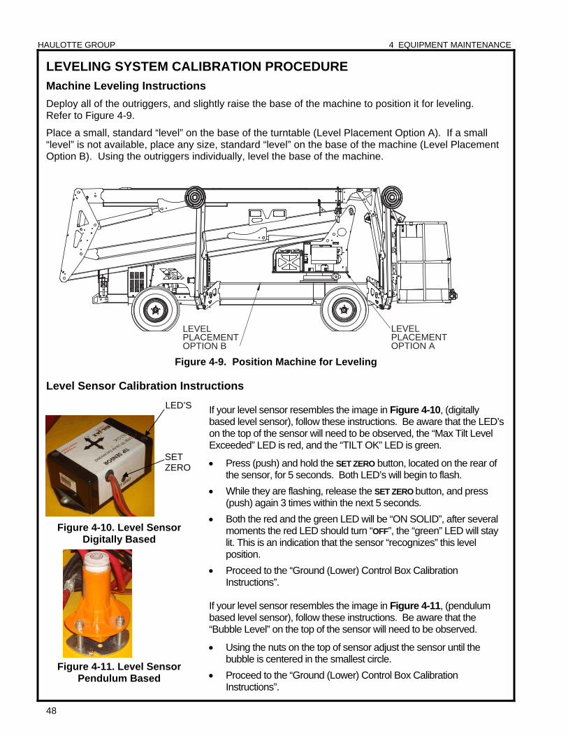
HAULOTTE GROUP 4 EQUIPMENT MAINTENANCE
48
LEVEL PLACEMENTOPTION A
LEVELPLACEMENTOPTION B
LEVELING SYSTEM CALIBRATION PROCEDURE
Machine Leveling Instructions
Deploy all of the outriggers, and slightly raise the base of the machine to position it for leveling. Refer to Figure 4-9.
Place a small, standard “level” on the base of the turntable (Level Placement Option A). If a small “level” is not available, place any size, standard “level” on the base of the machine (Level Placement Option B). Using the outriggers individually, level the base of the machine.
Figure 4-9. Position Machine for Leveling
Level Sensor Calibration Instructions
Figure 4-10. Level Sensor Digitally Based
Figure 4-11. Level Sensor
Pendulum Based
If your level sensor resembles the image in Figure 4-10, (digitally based level sensor), follow these instructions. Be aware that the LED’s on the top of the sensor will need to be observed, the “Max Tilt Level Exceeded” LED is red, and the “TILT OK” LED is green.
Press (push) and hold the SET ZERO button, located on the rear of the sensor, for 5 seconds. Both LED’s will begin to flash.
While they are flashing, release the SET ZERO button, and press (push) again 3 times within the next 5 seconds.
Both the red and the green LED will be “ON SOLID”, after several moments the red LED should turn “OFF”, the “green” LED will stay lit. This is an indication that the sensor “recognizes” this level position.
Proceed to the “Ground (Lower) Control Box Calibration Instructions”.
If your level sensor resembles the image in Figure 4-11, (pendulum based level sensor), follow these instructions. Be aware that the “Bubble Level” on the top of the sensor will need to be observed.
Using the nuts on the top of sensor adjust the sensor until the bubble is centered in the smallest circle.
Proceed to the “Ground (Lower) Control Box Calibration Instructions”.
LED’S
SET ZERO
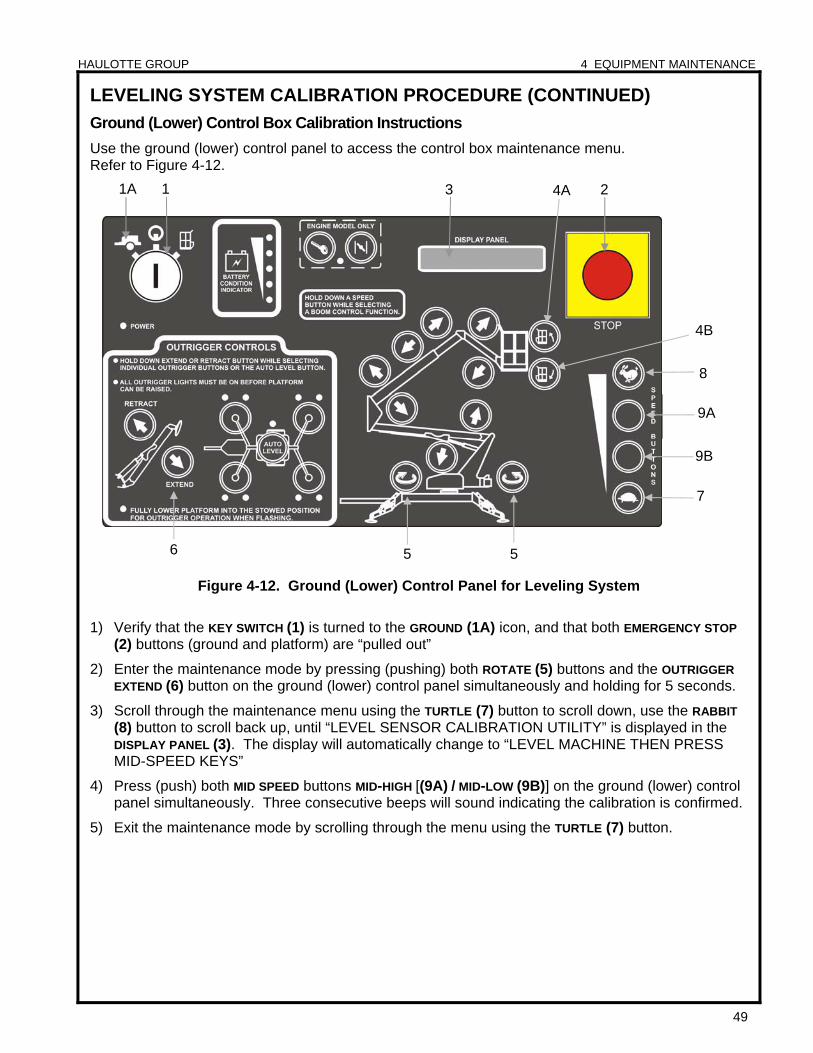
HAULOTTE GROUP 4 EQUIPMENT MAINTENANCE
49
LEVELING SYSTEM CALIBRATION PROCEDURE (CONTINUED)
Ground (Lower) Control Box Calibration Instructions
Use the ground (lower) control panel to access the control box maintenance menu. Refer to Figure 4-12.
Figure 4-12. Ground (Lower) Control Panel for Leveling System
1) Verify that the KEY SWITCH (1) is turned to the GROUND (1A) icon, and that both EMERGENCY STOP
(2) buttons (ground and platform) are “pulled out”
2) Enter the maintenance mode by pressing (pushing) both ROTATE (5) buttons and the OUTRIGGER
EXTEND (6) button on the ground (lower) control panel simultaneously and holding for 5 seconds.
3) Scroll through the maintenance menu using the TURTLE (7) button to scroll down, use the RABBIT
(8) button to scroll back up, until “LEVEL SENSOR CALIBRATION UTILITY” is displayed in the DISPLAY PANEL (3). The display will automatically change to “LEVEL MACHINE THEN PRESS MID-SPEED KEYS”
4) Press (push) both MID SPEED buttons MID-HIGH [(9A) / MID-LOW (9B)] on the ground (lower) control panel simultaneously. Three consecutive beeps will sound indicating the calibration is confirmed.
5) Exit the maintenance mode by scrolling through the menu using the TURTLE (7) button.
4A
9A
7
9B
8
4B
6 5 5
3 1 2 1A
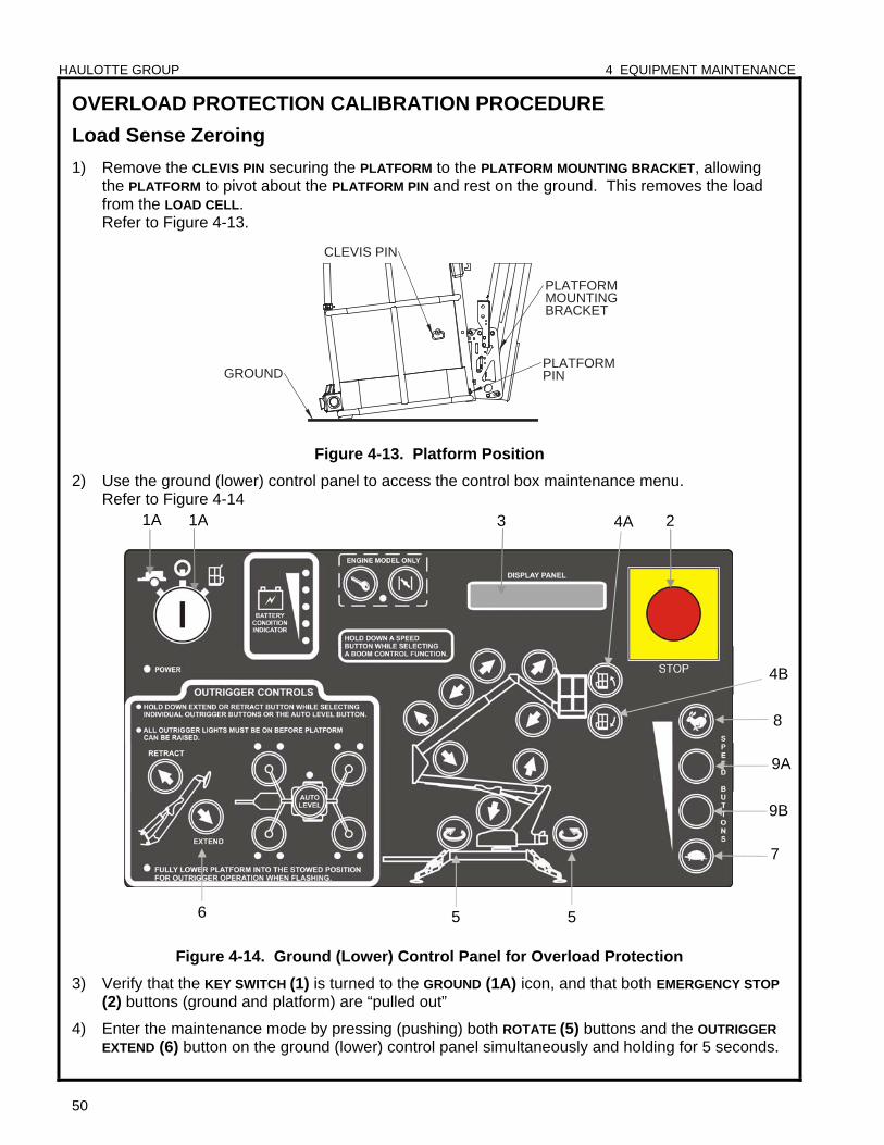
HAULOTTE GROUP 4 EQUIPMENT MAINTENANCE
50
CLEVIS PIN
PINPLATFORM
GROUND
PLATFORMMOUNTINGBRACKET
OVERLOAD PROTECTION CALIBRATION PROCEDURE
Load Sense Zeroing
1) Remove the CLEVIS PIN securing the PLATFORM to the PLATFORM MOUNTING BRACKET, allowing the PLATFORM to pivot about the PLATFORM PIN and rest on the ground. This removes the load from the LOAD CELL. Refer to Figure 4-13.
Figure 4-13. Platform Position
2) Use the ground (lower) control panel to access the control box maintenance menu. Refer to Figure 4-14
Figure 4-14. Ground (Lower) Control Panel for Overload Protection
3) Verify that the KEY SWITCH (1) is turned to the GROUND (1A) icon, and that both EMERGENCY STOP
(2) buttons (ground and platform) are “pulled out”
4) Enter the maintenance mode by pressing (pushing) both ROTATE (5) buttons and the OUTRIGGER
EXTEND (6) button on the ground (lower) control panel simultaneously and holding for 5 seconds.
4A
9A
7
9B
8
4B
6 5 5
3 1A 2 1A
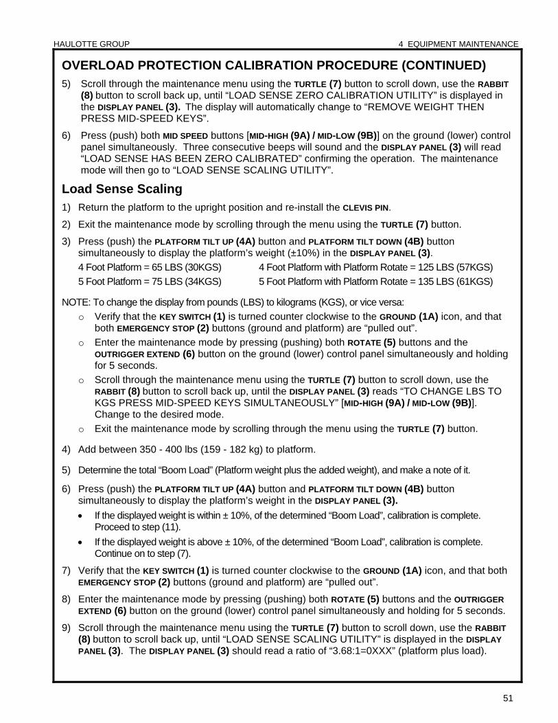
HAULOTTE GROUP 4 EQUIPMENT MAINTENANCE
51
OVERLOAD PROTECTION CALIBRATION PROCEDURE (CONTINUED) 5) Scroll through the maintenance menu using the TURTLE (7) button to scroll down, use the RABBIT
(8) button to scroll back up, until “LOAD SENSE ZERO CALIBRATION UTILITY” is displayed in the DISPLAY PANEL (3). The display will automatically change to “REMOVE WEIGHT THEN PRESS MID-SPEED KEYS”.
6) Press (push) both MID SPEED buttons [MID-HIGH (9A) / MID-LOW (9B)] on the ground (lower) control panel simultaneously. Three consecutive beeps will sound and the DISPLAY PANEL (3) will read “LOAD SENSE HAS BEEN ZERO CALIBRATED” confirming the operation. The maintenance mode will then go to “LOAD SENSE SCALING UTILITY”.
Load Sense Scaling 1) Return the platform to the upright position and re-install the CLEVIS PIN.
2) Exit the maintenance mode by scrolling through the menu using the TURTLE (7) button.
3) Press (push) the PLATFORM TILT UP (4A) button and PLATFORM TILT DOWN (4B) button simultaneously to display the platform’s weight (±10%) in the DISPLAY PANEL (3).
4 Foot Platform = 65 LBS (30KGS) 4 Foot Platform with Platform Rotate = 125 LBS (57KGS)
5 Foot Platform = 75 LBS (34KGS) 5 Foot Platform with Platform Rotate = 135 LBS (61KGS)
NOTE: To change the display from pounds (LBS) to kilograms (KGS), or vice versa:
o Verify that the KEY SWITCH (1) is turned counter clockwise to the GROUND (1A) icon, and that both EMERGENCY STOP (2) buttons (ground and platform) are “pulled out”.
o Enter the maintenance mode by pressing (pushing) both ROTATE (5) buttons and the OUTRIGGER EXTEND (6) button on the ground (lower) control panel simultaneously and holding for 5 seconds.
o Scroll through the maintenance menu using the TURTLE (7) button to scroll down, use the RABBIT (8) button to scroll back up, until the DISPLAY PANEL (3) reads “TO CHANGE LBS TO KGS PRESS MID-SPEED KEYS SIMULTANEOUSLY” [MID-HIGH (9A) / MID-LOW (9B)]. Change to the desired mode.
o Exit the maintenance mode by scrolling through the menu using the TURTLE (7) button.
4) Add between 350 - 400 lbs (159 - 182 kg) to platform.
5) Determine the total “Boom Load” (Platform weight plus the added weight), and make a note of it.
6) Press (push) the PLATFORM TILT UP (4A) button and PLATFORM TILT DOWN (4B) button simultaneously to display the platform’s weight in the DISPLAY PANEL (3).
If the displayed weight is within ± 10%, of the determined “Boom Load”, calibration is complete. Proceed to step (11).
If the displayed weight is above ± 10%, of the determined “Boom Load”, calibration is complete. Continue on to step (7).
7) Verify that the KEY SWITCH (1) is turned counter clockwise to the GROUND (1A) icon, and that both EMERGENCY STOP (2) buttons (ground and platform) are “pulled out”.
8) Enter the maintenance mode by pressing (pushing) both ROTATE (5) buttons and the OUTRIGGER
EXTEND (6) button on the ground (lower) control panel simultaneously and holding for 5 seconds.
9) Scroll through the maintenance menu using the TURTLE (7) button to scroll down, use the RABBIT
(8) button to scroll back up, until “LOAD SENSE SCALING UTILITY” is displayed in the DISPLAY
PANEL (3). The DISPLAY PANEL (3) should read a ratio of “3.68:1=0XXX” (platform plus load).
HAULOTTE GROUP 4 EQUIPMENT MAINTENANCE
52
OVERLOAD PROTECTION CALIBRATION PROCEDURE (CONTINUED) 10) Adjust displayed weight by pressing (pushing) the MID-HIGH (9) or MID-LOW (9) SPEED buttons until the
weight is within tolerances. The Ratio should be within 3.50:1 to 4.00:1. If so, continue on to Step 11. If the ratio is not within the above values, contact Haulotte Group Customer Service Department: at 1-800-537-0540 or visit Haulotte Group online at www.haulotte-usa.com
11) Exit the maintenance mode by scrolling through the menu using the TURTLE (7) button. Remove the weight from the platform. The Boom Load should now return to the weight of the platform.
12) Operate all functions in all speeds from both the ground (lower) and platform (upper) control panels to verify proper operation.
13) Recalibration is complete.
HAULOTTE GROUP 4 EQUIPMENT MAINTENANCE
53
ADDITIONAL SERVICE INFORMATION Seals on hydraulic cylinders should be replaced every five years or as indicated by aerial work platform performance.
All service checks should be performed on an aerial work platform that has been stored without use for a period exceeding thirty (30) days.
Check for air in the hydraulic system if the aerial work platform has been stored without use for a period exceeding thirty (30) days, or if the aerial work platform was stored without use during a seasonal climate change. Air trapped in the hydraulic system will affect aerial work platform performance. Follow procedures for bleeding air from the hydraulic system, found in the “Cylinder Replacement” section of this manual.
Owners and lessors should complete a full inspection of all components and perform a test of all functions, including brake functions, before commissioning or reselling the aerial work platform. Always repair or replace all damaged or malfunctioning components before commissioning or reselling an aerial work platform.
When a change in ownership occurs, it is the responsibility of the seller to provide the new owner with all manuals for the aerial work platform. It is the responsibility of the buyer to notify the manufacturer of the unit model and serial number and the name and address of the new owner within sixty (60) days of the purchase.
Use the service checklists found at the back of this manual to record all service checks as well as any maintenance, repairs or alterations performed on the aerial work platform.
Records of frequent safety checks need not be made. However, where a safety hazard is found, it shall be reported in writing to the owner of the aerial work platform, and a record of any corrective action shall be maintained for five years or as required by the authority having jurisdiction.
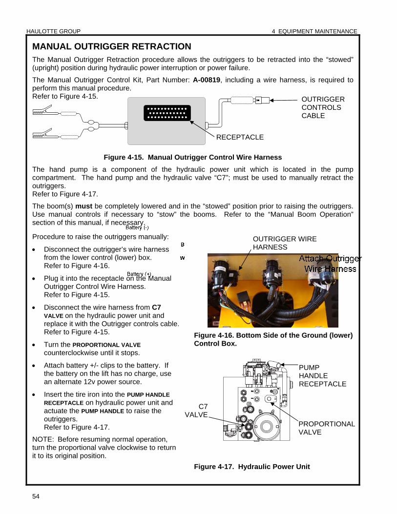
HAULOTTE GROUP 4 EQUIPMENT MAINTENANCE
54
MANUAL OUTRIGGER RETRACTION The Manual Outrigger Retraction procedure allows the outriggers to be retracted into the “stowed” (upright) position during hydraulic power interruption or power failure.
The Manual Outrigger Control Kit, Part Number: A-00819, including a wire harness, is required to perform this manual procedure. Refer to Figure 4-15.
Figure 4-15. Manual Outrigger Control Wire Harness
The hand pump is a component of the hydraulic power unit which is located in the pump compartment. The hand pump and the hydraulic valve “C7”; must be used to manually retract the outriggers. Refer to Figure 4-17.
The boom(s) must be completely lowered and in the “stowed” position prior to raising the outriggers. Use manual controls if necessary to “stow” the booms. Refer to the “Manual Boom Operation” section of this manual, if necessary.
Procedure to raise the outriggers manually:
Disconnect the outrigger’s wire harness from the lower control (lower) box. Refer to Figure 4-16.
Plug it into the receptacle on the Manual Outrigger Control Wire Harness. Refer to Figure 4-15.
Disconnect the wire harness from C7
VALVE on the hydraulic power unit and replace it with the Outrigger controls cable. Refer to Figure 4-15.
Turn the PROPORTIONAL VALVE counterclockwise until it stops.
Attach battery +/- clips to the battery. If the battery on the lift has no charge, use an alternate 12v power source.
Insert the tire iron into the PUMP HANDLE
RECEPTACLE on hydraulic power unit and actuate the PUMP HANDLE to raise the outriggers. Refer to Figure 4-17.
NOTE: Before resuming normal operation, turn the proportional valve clockwise to return it to its original position.
Figure 4-16. Bottom Side of the Ground (lower) Control Box.
Figure 4-17. Hydraulic Power Unit
OUTRIGGER WIRE HARNESS
PUMP HANDLE RECEPTACLE
C7 VALVE
PROPORTIONALVALVE
RECEPTACLE
OUTRIGGER CONTROLS CABLE
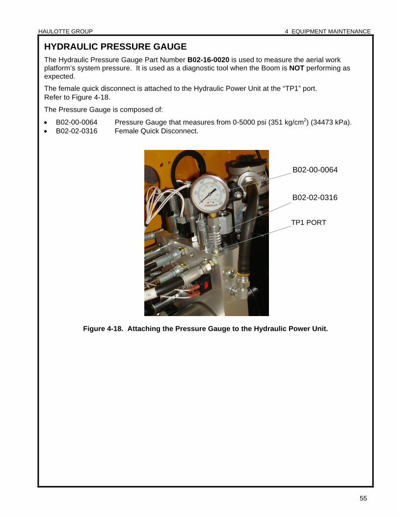
HAULOTTE GROUP 4 EQUIPMENT MAINTENANCE
55
HYDRAULIC PRESSURE GAUGE
The Hydraulic Pressure Gauge Part Number B02-16-0020 is used to measure the aerial work platform’s system pressure. It is used as a diagnostic tool when the Boom is NOT performing as expected.
The female quick disconnect is attached to the Hydraulic Power Unit at the “TP1” port. Refer to Figure 4-18.
The Pressure Gauge is composed of:
B02-00-0064 Pressure Gauge that measures from 0-5000 psi (351 kg/cm2) (34473 kPa). B02-02-0316 Female Quick Disconnect.
Figure 4-18. Attaching the Pressure Gauge to the Hydraulic Power Unit.
TP1 PORT
B02-00-0064
B02-02-0316
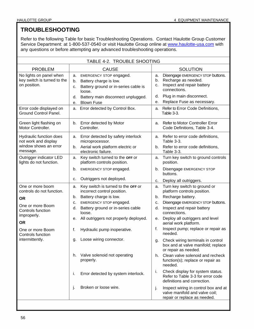
HAULOTTE GROUP 4 EQUIPMENT MAINTENANCE
56
TROUBLESHOOTING
Refer to the following Table for basic Troubleshooting Operations. Contact Haulotte Group Customer Service Department: at 1-800-537-0540 or visit Haulotte Group online at www.haulotte-usa.com with any questions or before attempting any advanced troubleshooting operations.
TABLE 4-2. TROUBLE SHOOTING
PROBLEM CAUSE SOLUTION No lights on panel when key switch is turned to the on position.
a. EMERGENCY STOP engaged. b. Battery charge is low. c. Battery ground or in-series cable is
loose. d. Battery main disconnect unplugged. e. Blown Fuse
a. Disengage EMERGENCY STOP buttons. b. Recharge as needed. c. Inspect and repair battery
connections.
d. Plug in main disconnect. e. Replace Fuse as necessary.
Error code displayed on Ground Control Panel.
a. Error detected by Control Box. a. Refer to Error Code Definitions, Table 3-3.
Green light flashing on Motor Controller.
b. Error detected by Motor Controller.
a. Refer to Motor Controller Error Code Definitions, Table 3-4.
Hydraulic function does not work and display window shows an error message.
a. Error detected by safety interlock microprocessor.
b. Aerial work platform electric or electronic failure.
a. Refer to error code definitions, Table 3-3.
b. Refer to error code definitions, Table 3-3.
Outrigger indicator LED lights do not function.
a. Key switch turned to the OFF or platform controls position.
b. EMERGENCY STOP engaged.
c. Outriggers not deployed.
a. Turn key switch to ground controls position.
b. Disengage EMERGENCY STOP buttons.
c. Deploy all outriggers. One or more boom controls do not function.
OR
One or more Boom Controls function improperly.
OR
One or more Boom Controls function intermittently.
a. Key switch is turned to the OFF or incorrect control position.
b. Battery charge is low. c. EMERGENCY STOP engaged. d. Battery ground or in-series cable
loose. e. All outriggers not properly deployed.
f. Hydraulic pump inoperative.
g. Loose wiring connector.
h. Valve solenoid not operating properly.
i. Error detected by system interlock.
j. Broken or loose wire.
a. Turn key switch to ground or platform controls position.
b. Recharge battery. c. Disengage EMERGENCY STOP buttons. d. Inspect and repair battery
connections. e. Deploy all outriggers and level
aerial work platform. f. Inspect pump; replace or repair as
needed.
g. Check wiring terminals in control box and at valve manifold; replace or repair as needed.
h. Clean valve solenoid and recheck function(s); replace or repair as needed.
i. Check display for system status. Refer to Table 3-3 for error code definitions and correction.
j. Inspect wiring in control box and at valve manifold and valve coil; repair or replace as needed.
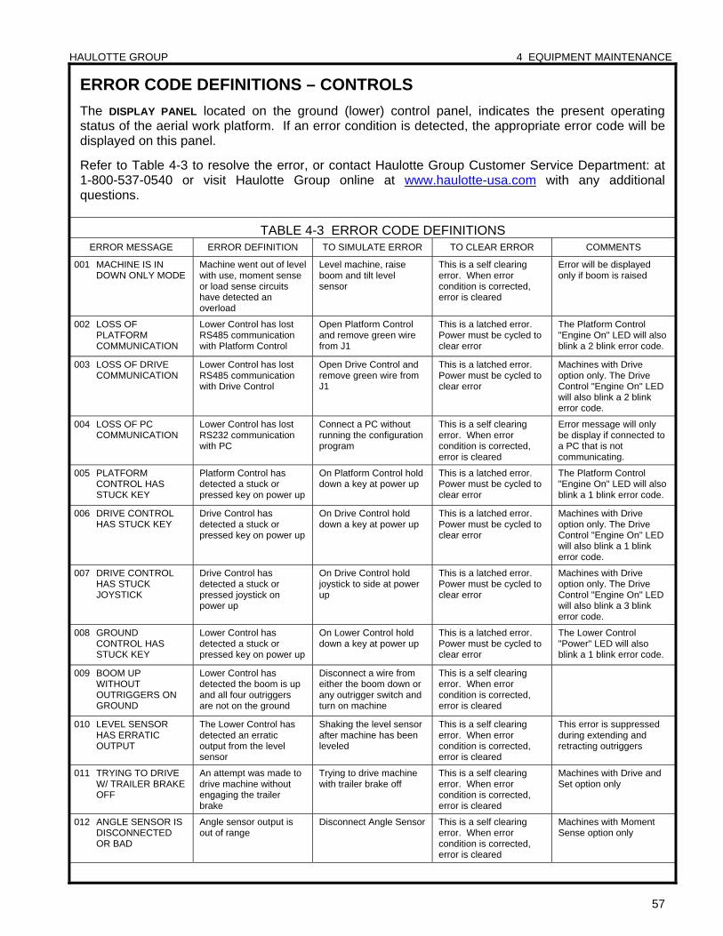
HAULOTTE GROUP 4 EQUIPMENT MAINTENANCE
57
ERROR CODE DEFINITIONS – CONTROLS
The DISPLAY PANEL located on the ground (lower) control panel, indicates the present operating status of the aerial work platform. If an error condition is detected, the appropriate error code will be displayed on this panel.
Refer to Table 4-3 to resolve the error, or contact Haulotte Group Customer Service Department: at 1-800-537-0540 or visit Haulotte Group online at www.haulotte-usa.com with any additional questions.
TABLE 4-3 ERROR CODE DEFINITIONS ERROR MESSAGE ERROR DEFINITION TO SIMULATE ERROR TO CLEAR ERROR COMMENTS
001 MACHINE IS IN DOWN ONLY MODE
Machine went out of level with use, moment sense or load sense circuits have detected an overload
Level machine, raise boom and tilt level sensor
This is a self clearing error. When error condition is corrected, error is cleared
Error will be displayed only if boom is raised
002 LOSS OF PLATFORM COMMUNICATION
Lower Control has lost RS485 communication with Platform Control
Open Platform Control and remove green wire from J1
This is a latched error. Power must be cycled to clear error
The Platform Control "Engine On" LED will also blink a 2 blink error code.
003 LOSS OF DRIVE COMMUNICATION
Lower Control has lost RS485 communication with Drive Control
Open Drive Control and remove green wire from J1
This is a latched error. Power must be cycled to clear error
Machines with Drive option only. The Drive Control "Engine On" LED will also blink a 2 blink error code.
004 LOSS OF PC COMMUNICATION
Lower Control has lost RS232 communication with PC
Connect a PC without running the configuration program
This is a self clearing error. When error condition is corrected, error is cleared
Error message will only be display if connected to a PC that is not communicating.
005 PLATFORM CONTROL HAS STUCK KEY
Platform Control has detected a stuck or pressed key on power up
On Platform Control hold down a key at power up
This is a latched error. Power must be cycled to clear error
The Platform Control "Engine On" LED will also blink a 1 blink error code.
006 DRIVE CONTROL HAS STUCK KEY
Drive Control has detected a stuck or pressed key on power up
On Drive Control hold down a key at power up
This is a latched error. Power must be cycled to clear error
Machines with Drive option only. The Drive Control "Engine On" LED will also blink a 1 blink error code.
007 DRIVE CONTROL HAS STUCK JOYSTICK
Drive Control has detected a stuck or pressed joystick on power up
On Drive Control hold joystick to side at power up
This is a latched error. Power must be cycled to clear error
Machines with Drive option only. The Drive Control "Engine On" LED will also blink a 3 blink error code.
008 GROUND CONTROL HAS STUCK KEY
Lower Control has detected a stuck or pressed key on power up
On Lower Control hold down a key at power up
This is a latched error. Power must be cycled to clear error
The Lower Control "Power" LED will also blink a 1 blink error code.
009 BOOM UP WITHOUT OUTRIGGERS ON GROUND
Lower Control has detected the boom is up and all four outriggers are not on the ground
Disconnect a wire from either the boom down or any outrigger switch and turn on machine
This is a self clearing error. When error condition is corrected, error is cleared
010 LEVEL SENSOR HAS ERRATIC OUTPUT
The Lower Control has detected an erratic output from the level sensor
Shaking the level sensor after machine has been leveled
This is a self clearing error. When error condition is corrected, error is cleared
This error is suppressed during extending and retracting outriggers
011 TRYING TO DRIVE W/ TRAILER BRAKE OFF
An attempt was made to drive machine without engaging the trailer brake
Trying to drive machine with trailer brake off
This is a self clearing error. When error condition is corrected, error is cleared
Machines with Drive and Set option only
012 ANGLE SENSOR IS DISCONNECTED OR BAD
Angle sensor output is out of range
Disconnect Angle Sensor This is a self clearing error. When error condition is corrected, error is cleared
Machines with Moment Sense option only
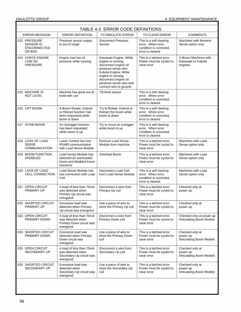
HAULOTTE GROUP 4 EQUIPMENT MAINTENANCE
58
TABLE 4-3 ERROR CODE DEFINITIONS ERROR MESSAGE ERROR DEFINITION TO SIMULATE ERROR TO CLEAR ERROR COMMENTS
013 PRESSURE SENSOR IS DISCONNECTED OR BAD
Pressure sensor output is out of range
Disconnect Pressure Sensor
This is a self clearing error. When error condition is corrected, error is cleared
Machines with Moment Sense option only
014 CHECK ENGINE LOW OIL PRESSURE
Engine had low oil pressure while running
Kawasaki Engine: While engine is running, disconnect engine oil pressure sense wire Kubota Engine: While engine is running, disconnect engine oil pressure sense wire and connect wire to ground
This is a latched error. Power must be cycled to clear error
X-Boom Machines with Kawasaki or Kubota engines
015 MACHINE IS NOT LEVEL
Machine has gone out of level with use
Tilt level sensor This is a self clearing error. When error condition is corrected, error is cleared
016 LIFT BOOM A Boom Rotate, Extend or Retract function has been requested while boom is down
Try to Rotate, Extend or Retract the boom while boom is down
This is a self clearing error. When error condition is corrected, error is cleared
017 STOW BOOM An Outrigger function has been requested while boom is up
Try to move an outrigger while boom is up
This is a self clearing error. When error condition is corrected, error is cleared
018 LOSS OF LOAD SENSE COMMUNICATION
Lower Control has lost RS485 communication with Load Sense Module
Remove Load Sense Module from machine
This is a latched error. Power must be cycled to clear error
Machines with Load Sense option only
019 BOOM FUNCTION DISABLED
Load Sense Module has detected an overloaded boom and disabled boom functions
Overload Boom This is a latched error. Power must be cycled to clear error
Machines with Load Sense option only
020 LOSS OF LOAD CELL CONNECTION
Load Sense Module has lost connection with Load Cell
Disconnect Load Cell from Load Sense Module
This is a self clearing error. When error condition is corrected, error is cleared
Machines with Load Sense option only
021 OPEN CIRCUIT PRIMARY UP
A load of less than 70mA was detected when Primary Up circuit was energized
Disconnect a wire from Primary Up coil
This is a latched error. Power must be cycled to clear error
Checked only at power up
022 SHORTED CIRCUIT PRIMARY UP
Excessive load was detected when Primary Up circuit was energized
Use a piece of wire to short the Primary Up coil
This is a latched error. Power must be cycled to clear error
Checked only at power up
023 OPEN CIRCUIT PRIMARY DOWN
A load of less than 70mA was detected when Primary Down circuit was energized
Disconnect a wire from Primary Down coil
This is a latched error. Power must be cycled to clear error
Checked only at power up Articulating Boom Models
024 SHORTED CIRCUIT PRIMARY DOWN
Excessive load was detected when Primary Down circuit was energized
Use a piece of wire to short the Primary Down coil
This is a latched error. Power must be cycled to clear error
Checked only at power up Articulating Boom Models
025 OPEN CIRCUIT SECONDARY UP
A load of less than 70mA was detected when Secondary Up circuit was energized
Disconnect a wire from Secondary Up coil
This is a latched error. Power must be cycled to clear error
Checked only at power up Articulating Boom Models
026 SHORTED CIRCUIT SECONDARY UP
Excessive load was detected when Secondary Up circuit was energized
Use a piece of wire to short the Secondary Up coil
This is a latched error. Power must be cycled to clear error
Checked only at power up Articulating Boom Models
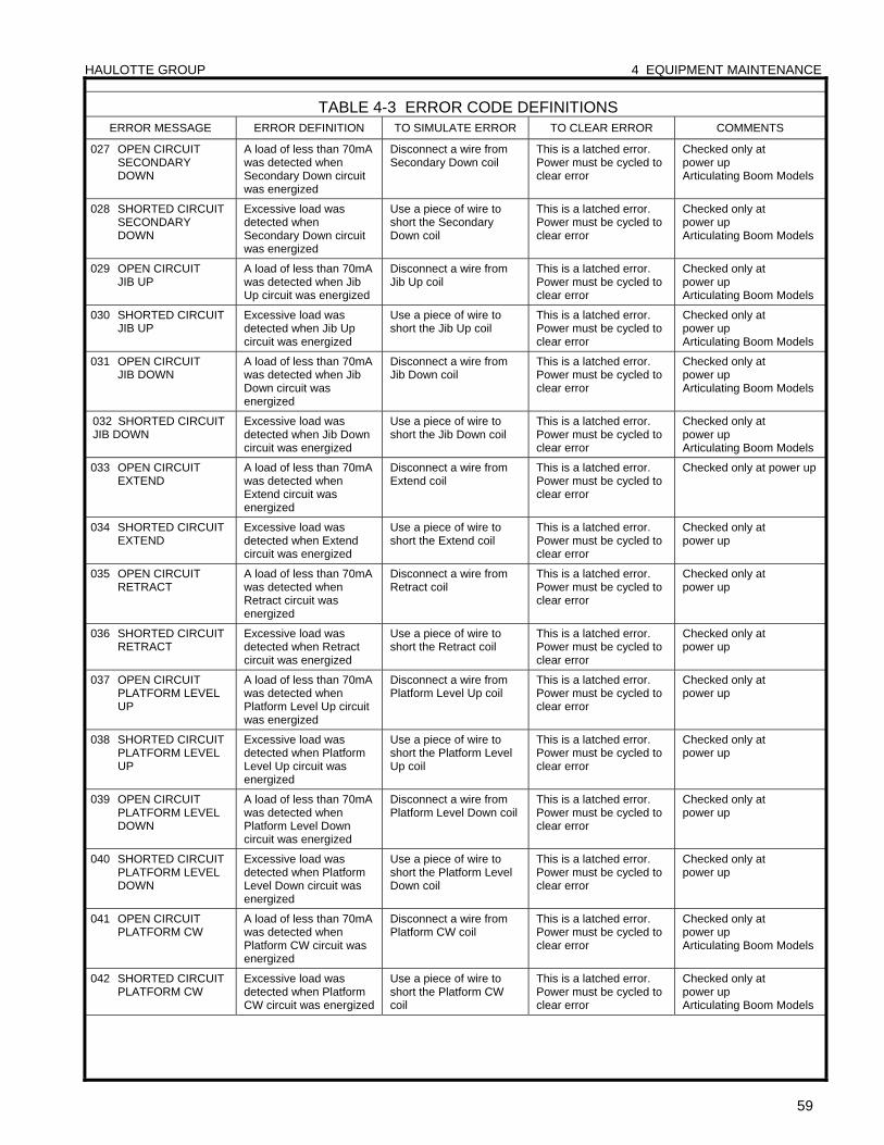
HAULOTTE GROUP 4 EQUIPMENT MAINTENANCE
59
TABLE 4-3 ERROR CODE DEFINITIONS ERROR MESSAGE ERROR DEFINITION TO SIMULATE ERROR TO CLEAR ERROR COMMENTS
027 OPEN CIRCUIT SECONDARY DOWN
A load of less than 70mA was detected when Secondary Down circuit was energized
Disconnect a wire from Secondary Down coil
This is a latched error. Power must be cycled to clear error
Checked only at power up Articulating Boom Models
028 SHORTED CIRCUIT SECONDARY DOWN
Excessive load was detected when Secondary Down circuit was energized
Use a piece of wire to short the Secondary Down coil
This is a latched error. Power must be cycled to clear error
Checked only at power up Articulating Boom Models
029 OPEN CIRCUIT JIB UP
A load of less than 70mA was detected when Jib Up circuit was energized
Disconnect a wire from Jib Up coil
This is a latched error. Power must be cycled to clear error
Checked only at power up Articulating Boom Models
030 SHORTED CIRCUIT JIB UP
Excessive load was detected when Jib Up circuit was energized
Use a piece of wire to short the Jib Up coil
This is a latched error. Power must be cycled to clear error
Checked only at power up Articulating Boom Models
031 OPEN CIRCUIT JIB DOWN
A load of less than 70mA was detected when Jib Down circuit was energized
Disconnect a wire from Jib Down coil
This is a latched error. Power must be cycled to clear error
Checked only at power up Articulating Boom Models
032 SHORTED CIRCUIT JIB DOWN
Excessive load was detected when Jib Down circuit was energized
Use a piece of wire to short the Jib Down coil
This is a latched error. Power must be cycled to clear error
Checked only at power up Articulating Boom Models
033 OPEN CIRCUIT EXTEND
A load of less than 70mA was detected when Extend circuit was energized
Disconnect a wire from Extend coil
This is a latched error. Power must be cycled to clear error
Checked only at power up
034 SHORTED CIRCUIT EXTEND
Excessive load was detected when Extend circuit was energized
Use a piece of wire to short the Extend coil
This is a latched error. Power must be cycled to clear error
Checked only at power up
035 OPEN CIRCUIT RETRACT
A load of less than 70mA was detected when Retract circuit was energized
Disconnect a wire from Retract coil
This is a latched error. Power must be cycled to clear error
Checked only at power up
036 SHORTED CIRCUIT RETRACT
Excessive load was detected when Retract circuit was energized
Use a piece of wire to short the Retract coil
This is a latched error. Power must be cycled to clear error
Checked only at power up
037 OPEN CIRCUIT PLATFORM LEVEL UP
A load of less than 70mA was detected when Platform Level Up circuit was energized
Disconnect a wire from Platform Level Up coil
This is a latched error. Power must be cycled to clear error
Checked only at power up
038 SHORTED CIRCUIT PLATFORM LEVEL UP
Excessive load was detected when Platform Level Up circuit was energized
Use a piece of wire to short the Platform Level Up coil
This is a latched error. Power must be cycled to clear error
Checked only at power up
039 OPEN CIRCUIT PLATFORM LEVEL DOWN
A load of less than 70mA was detected when Platform Level Down circuit was energized
Disconnect a wire from Platform Level Down coil
This is a latched error. Power must be cycled to clear error
Checked only at power up
040 SHORTED CIRCUIT PLATFORM LEVEL DOWN
Excessive load was detected when Platform Level Down circuit was energized
Use a piece of wire to short the Platform Level Down coil
This is a latched error. Power must be cycled to clear error
Checked only at power up
041 OPEN CIRCUIT PLATFORM CW
A load of less than 70mA was detected when Platform CW circuit was energized
Disconnect a wire from Platform CW coil
This is a latched error. Power must be cycled to clear error
Checked only at power up Articulating Boom Models
042 SHORTED CIRCUIT PLATFORM CW
Excessive load was detected when Platform CW circuit was energized
Use a piece of wire to short the Platform CW coil
This is a latched error. Power must be cycled to clear error
Checked only at power up Articulating Boom Models
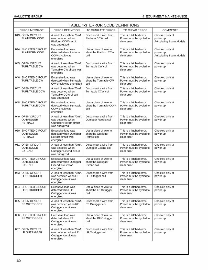
HAULOTTE GROUP 4 EQUIPMENT MAINTENANCE
60
TABLE 4-3 ERROR CODE DEFINITIONS ERROR MESSAGE ERROR DEFINITION TO SIMULATE ERROR TO CLEAR ERROR COMMENTS
043 OPEN CIRCUIT PLATFORM CCW
A load of less than 70mA was detected when Platform CCW circuit was energized
Disconnect a wire from Platform CCW coil
This is a latched error. Power must be cycled to clear error
Checked only at power up Articulating Boom Models
044 SHORTED CIRCUIT PLATFORM CCW
Excessive load was detected when Platform CCW circuit was energized
Use a piece of wire to short the Platform CCW coil
This is a latched error. Power must be cycled to clear error
Checked only at power up Articulating Boom Models
045 OPEN CIRCUIT TURNTABLE CW
A load of less than 70mA was detected when Turntable CW circuit was energized
Disconnect a wire from Turntable CW coil
This is a latched error. Power must be cycled to clear error
Checked only at power up
046 SHORTED CIRCUIT TURNTABLE CW
Excessive load was detected when Turntable CW circuit was energized
Use a piece of wire to short the Turntable CW coil
This is a latched error. Power must be cycled to clear error
Checked only at power up
047 OPEN CIRCUIT TURNTABLE CCW
A load of less than 70mA was detected when Turntable CCW circuit was energized
Disconnect a wire from Turntable CCW coil
This is a latched error. Power must be cycled to clear error
Checked only at power up
048 SHORTED CIRCUIT TURNTABLE CCW
Excessive load was detected when Turntable CCW circuit was energized
Use a piece of wire to short the Turntable CCW coil
This is a latched error. Power must be cycled to clear error
Checked only at power up
049 OPEN CIRCUIT OUTRIGGER RETRACT
A load of less than 70mA was detected when Outrigger Retract circuit was energized
Disconnect a wire from Outrigger Retract coil
This is a latched error. Power must be cycled to clear error
Checked only at power up
050 SHORTED CIRCUIT OUTRIGGER RETRACT
Excessive load was detected when Outrigger Retract circuit was energized
Use a piece of wire to short the Outrigger Retract coil
This is a latched error. Power must be cycled to clear error
Checked only at power up
051 OPEN CIRCUIT OUTRIGGER EXTEND
A load of less than 70mA was detected when Outrigger Extend circuit was energized
Disconnect a wire from Outrigger Extend coil
This is a latched error. Power must be cycled to clear error
Checked only at power up
052 SHORTED CIRCUIT OUTRIGGER EXTEND
Excessive load was detected when Outrigger Extend circuit was energized
Use a piece of wire to short the Outrigger Extend coil
This is a latched error. Power must be cycled to clear error
Checked only at power up
053 OPEN CIRCUIT LF OUTRIGGER
A load of less than 70mA was detected when LF Outrigger circuit was energized
Disconnect a wire from LF Outrigger coil
This is a latched error. Power must be cycled to clear error
Checked only at power up
054 SHORTED CIRCUIT LF OUTRIGGER
Excessive load was detected when LF Outrigger circuit was energized
Use a piece of wire to short the LF Outrigger coil
This is a latched error. Power must be cycled to clear error
Checked only at power up
055 OPEN CIRCUIT RF OUTRIGGER
A load of less than 70mA was detected when RF Outrigger circuit was energized
Disconnect a wire from RF Outrigger coil
This is a latched error. Power must be cycled to clear error
Checked only at power up
056 SHORTED CIRCUIT RF OUTRIGGER
Excessive load was detected when RF Outrigger circuit was energized
Use a piece of wire to short the RF Outrigger coil
This is a latched error. Power must be cycled to clear error
Checked only at power up
057 OPEN CIRCUIT LR OUTRIGGER
A load of less than 70mA was detected when LR Outrigger circuit was energized
Disconnect a wire from LR Outrigger coil
This is a latched error. Power must be cycled to clear error
Checked only at power up
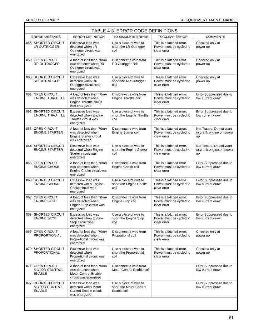
HAULOTTE GROUP 4 EQUIPMENT MAINTENANCE
61
TABLE 4-3 ERROR CODE DEFINITIONS ERROR MESSAGE ERROR DEFINITION TO SIMULATE ERROR TO CLEAR ERROR COMMENTS
058 SHORTED CIRCUIT LR OUTRIGGER
Excessive load was detected when LR Outrigger circuit was energized
Use a piece of wire to short the LR Outrigger coil
This is a latched error. Power must be cycled to clear error
Checked only at power up
059 OPEN CIRCUIT RR OUTRIGGER
A load of less than 70mA was detected when RR Outrigger circuit was energized
Disconnect a wire from RR Outrigger coil
This is a latched error. Power must be cycled to clear error
Checked only at power up
060 SHORTED CIRCUIT RR OUTRIGGER
Excessive load was detected when RR Outrigger circuit was energized
Use a piece of wire to short the RR Outrigger coil
This is a latched error. Power must be cycled to clear error
Checked only at power up
061 OPEN CIRCUIT ENGINE THROTTLE
A load of less than 70mA was detected when Engine Throttle circuit was energized
Disconnect a wire from Engine Throttle coil
This is a latched error. Power must be cycled to clear error
Error Suppressed due to low current draw
062 SHORTED CIRCUIT ENGINE THROTTLE
Excessive load was detected when Engine Throttle circuit was energized
Use a piece of wire to short the Engine Throttle coil
This is a latched error. Power must be cycled to clear error
Error Suppressed due to low current draw
063 OPEN CIRCUIT ENGINE STARTER
A load of less than 70mA was detected when Engine Starter circuit was energized
Disconnect a wire from Engine Starter coil
This is a latched error. Power must be cycled to clear error
Not Tested, Do not want to crank engine on power up
064 SHORTED CIRCUIT ENGINE STARTER
Excessive load was detected when Engine Starter circuit was energized
Use a piece of wire to short the Engine Starter coil
This is a latched error. Power must be cycled to clear error
Not Tested, Do not want to crank engine on power up
065 OPEN CIRCUIT ENGINE CHOKE
A load of less than 70mA was detected when Engine Choke circuit was energized
Disconnect a wire from Engine Choke coil
This is a latched error. Power must be cycled to clear error
Error Suppressed due to low current draw
066 SHORTED CIRCUIT ENGINE CHOKE
Excessive load was detected when Engine Choke circuit was energized
Use a piece of wire to short the Engine Choke coil
This is a latched error. Power must be cycled to clear error
Error Suppressed due to low current draw
067 OPEN CIRCUIT ENGINE STOP
A load of less than 70mA was detected when Engine Stop circuit was energized
Disconnect a wire from Engine Stop coil
This is a latched error. Power must be cycled to clear error
Error Suppressed due to low current draw
068 SHORTED CIRCUIT ENGINE STOP
Excessive load was detected when Engine Stop circuit was energized
Use a piece of wire to short the Engine Stop coil
This is a latched error. Power must be cycled to clear error
Error Suppressed due to low current draw
069 OPEN CIRCUIT PROPORTION-AL
A load of less than 70mA was detected when Proportional circuit was energized
Disconnect a wire from Proportional coil
This is a latched error. Power must be cycled to clear error
Checked only at power up
070 SHORTED CIRCUIT PROPORTIONAL
Excessive load was detected when Proportional circuit was energized
Use a piece of wire to short the Proportional coil
This is a latched error. Power must be cycled to clear error
Checked only at power up
071 OPEN CIRCUIT MOTOR CONTROL ENABLE
A load of less than 70mA was detected when Motor Control Enable circuit was energized
Disconnect a wire from Motor Control Enable coil
Error Suppressed due to low current draw
072 SHORTED CIRCUIT MOTOR CONTROL ENABLE
Excessive load was detected when Motor Control Enable circuit was energized
Use a piece of wire to short the Motor Control Enable coil
Error Suppressed due to low current draw
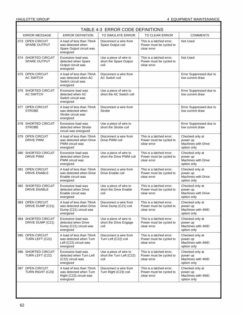
HAULOTTE GROUP 4 EQUIPMENT MAINTENANCE
62
TABLE 4-3 ERROR CODE DEFINITIONS ERROR MESSAGE ERROR DEFINITION TO SIMULATE ERROR TO CLEAR ERROR COMMENTS
073 OPEN CIRCUIT SPARE OUTPUT
A load of less than 70mA was detected when Spare Output circuit was energized
Disconnect a wire from Spare Output coil
This is a latched error. Power must be cycled to clear error
Not Used
074 SHORTED CIRCUIT SPARE OUTPUT
Excessive load was detected when Spare Output circuit was energized
Use a piece of wire to short the Spare Output coil
This is a latched error. Power must be cycled to clear error
Not Used
075 OPEN CIRCUIT AC SWITCH
A load of less than 70mA was detected when AC Switch circuit was energized
Disconnect a wire from AC Switch coil
Error Suppressed due to low current draw
076 SHORTED CIRCUIT AC SWITCH
Excessive load was detected when AC Switch circuit was energized
Use a piece of wire to short the AC Switch coil
Error Suppressed due to low current draw
077 OPEN CIRCUIT STROBE
A load of less than 70mA was detected when Strobe circuit was energized
Disconnect a wire from Strobe
Error Suppressed due to low current draw
078 SHORTED CIRCUIT STROBE
Excessive load was detected when Strobe circuit was energized
Use a piece of wire to short the Strobe coil
Error Suppressed due to low current draw
079 OPEN CIRCUIT DRIVE PWM
A load of less than 70mA was detected when Drive PWM circuit was energized
Disconnect a wire from Drive PWM coil
This is a latched error. Power must be cycled to clear error
Checked only at power up Machines with Drive option only
080 SHORTED CIRCUIT DRIVE PWM
Excessive load was detected when Drive PWM circuit was energized
Use a piece of wire to short the Drive PWM coil
This is a latched error. Power must be cycled to clear error
Checked only at power up Machines with Drive option only
081 OPEN CIRCUIT DRIVE ENABLE
A load of less than 70mA was detected when Drive Enable circuit was energized
Disconnect a wire from Drive Enable coil
This is a latched error. Power must be cycled to clear error
Checked only at power up Machines with Drive option only
082 SHORTED CIRCUIT DRIVE ENABLE
Excessive load was detected when Drive Enable circuit was energized
Use a piece of wire to short the Drive Enable coil
This is a latched error. Power must be cycled to clear error
Checked only at power up Machines with Drive option only
083 OPEN CIRCUIT DRIVE DUMP (C21)
A load of less than 70mA was detected when Drive Dump (C21) circuit was energized
Disconnect a wire from Drive Dump (C21) coil
This is a latched error. Power must be cycled to clear error
Checked only at power up Machines with 4WD option only
084 SHORTED CIRCUIT DRIVE DUMP (C21)
Excessive load was detected when Drive Dump (C21) circuit was energized
Use a piece of wire to short the Drive Engage coil
This is a latched error. Power must be cycled to clear error
Checked only at power up Machines with 4WD option only
085 OPEN CIRCUIT TURN LEFT (C22)
A load of less than 70mA was detected when Turn Left (C22) circuit was energized
Disconnect a wire from Turn Left (C22) coil
This is a latched error. Power must be cycled to clear error
Checked only at power up Machines with 4WD option only
086 SHORTED CIRCUIT TURN LEFT (C22)
Excessive load was detected when Turn Left (C22) circuit was energized
Use a piece of wire to short the Turn Left (C22) coil
This is a latched error. Power must be cycled to clear error
Checked only at power up Machines with 4WD option only
087 OPEN CIRCUIT TURN RIGHT (C23)
A load of less than 70mA was detected when Turn Right (C23) circuit was energized
Disconnect a wire from Turn Right (C23) coil
This is a latched error. Power must be cycled to clear error
Checked only at power up Machines with 4WD option only
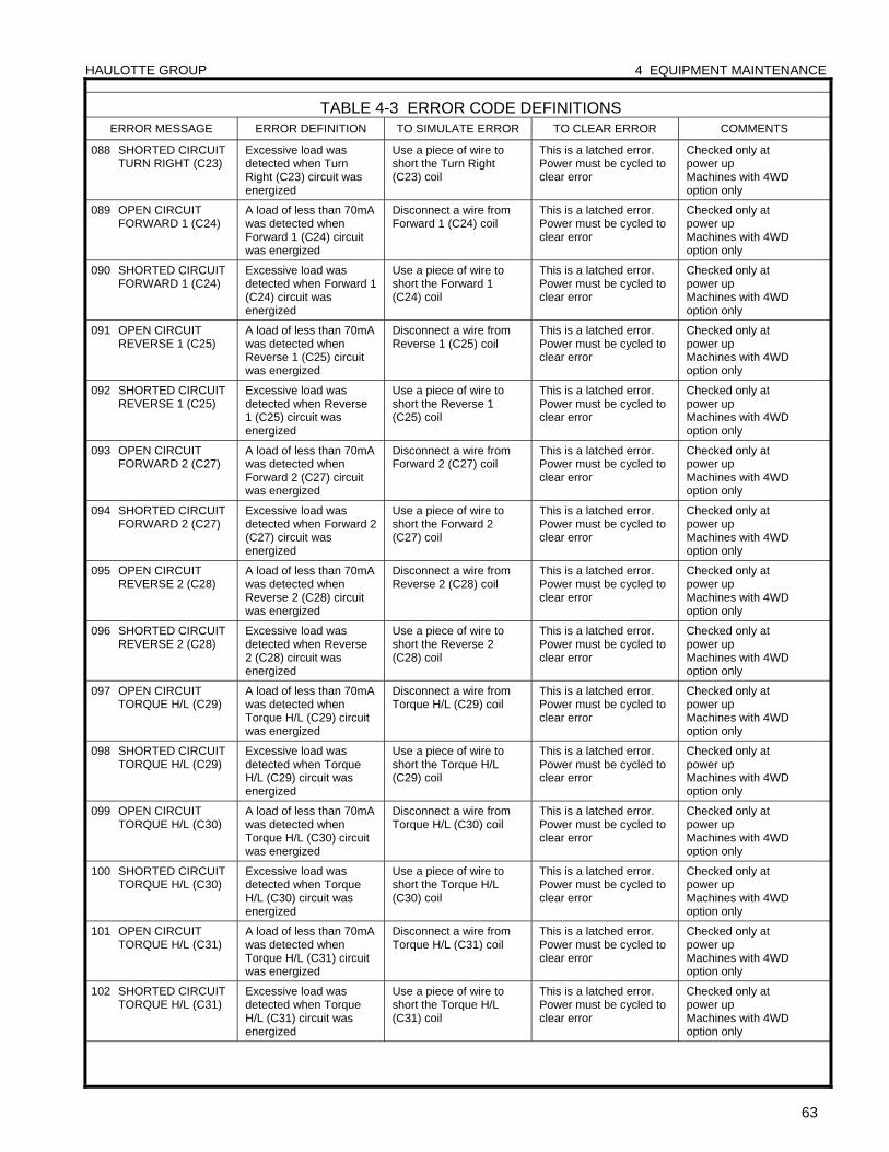
HAULOTTE GROUP 4 EQUIPMENT MAINTENANCE
63
TABLE 4-3 ERROR CODE DEFINITIONS ERROR MESSAGE ERROR DEFINITION TO SIMULATE ERROR TO CLEAR ERROR COMMENTS
088 SHORTED CIRCUIT TURN RIGHT (C23)
Excessive load was detected when Turn Right (C23) circuit was energized
Use a piece of wire to short the Turn Right (C23) coil
This is a latched error. Power must be cycled to clear error
Checked only at power up Machines with 4WD option only
089 OPEN CIRCUIT FORWARD 1 (C24)
A load of less than 70mA was detected when Forward 1 (C24) circuit was energized
Disconnect a wire from Forward 1 (C24) coil
This is a latched error. Power must be cycled to clear error
Checked only at power up Machines with 4WD option only
090 SHORTED CIRCUIT FORWARD 1 (C24)
Excessive load was detected when Forward 1 (C24) circuit was energized
Use a piece of wire to short the Forward 1 (C24) coil
This is a latched error. Power must be cycled to clear error
Checked only at power up Machines with 4WD option only
091 OPEN CIRCUIT REVERSE 1 (C25)
A load of less than 70mA was detected when Reverse 1 (C25) circuit was energized
Disconnect a wire from Reverse 1 (C25) coil
This is a latched error. Power must be cycled to clear error
Checked only at power up Machines with 4WD option only
092 SHORTED CIRCUIT REVERSE 1 (C25)
Excessive load was detected when Reverse 1 (C25) circuit was energized
Use a piece of wire to short the Reverse 1 (C25) coil
This is a latched error. Power must be cycled to clear error
Checked only at power up Machines with 4WD option only
093 OPEN CIRCUIT FORWARD 2 (C27)
A load of less than 70mA was detected when Forward 2 (C27) circuit was energized
Disconnect a wire from Forward 2 (C27) coil
This is a latched error. Power must be cycled to clear error
Checked only at power up Machines with 4WD option only
094 SHORTED CIRCUIT FORWARD 2 (C27)
Excessive load was detected when Forward 2 (C27) circuit was energized
Use a piece of wire to short the Forward 2 (C27) coil
This is a latched error. Power must be cycled to clear error
Checked only at power up Machines with 4WD option only
095 OPEN CIRCUIT REVERSE 2 (C28)
A load of less than 70mA was detected when Reverse 2 (C28) circuit was energized
Disconnect a wire from Reverse 2 (C28) coil
This is a latched error. Power must be cycled to clear error
Checked only at power up Machines with 4WD option only
096 SHORTED CIRCUIT REVERSE 2 (C28)
Excessive load was detected when Reverse 2 (C28) circuit was energized
Use a piece of wire to short the Reverse 2 (C28) coil
This is a latched error. Power must be cycled to clear error
Checked only at power up Machines with 4WD option only
097 OPEN CIRCUIT TORQUE H/L (C29)
A load of less than 70mA was detected when Torque H/L (C29) circuit was energized
Disconnect a wire from Torque H/L (C29) coil
This is a latched error. Power must be cycled to clear error
Checked only at power up Machines with 4WD option only
098 SHORTED CIRCUIT TORQUE H/L (C29)
Excessive load was detected when Torque H/L (C29) circuit was energized
Use a piece of wire to short the Torque H/L (C29) coil
This is a latched error. Power must be cycled to clear error
Checked only at power up Machines with 4WD option only
099 OPEN CIRCUIT TORQUE H/L (C30)
A load of less than 70mA was detected when Torque H/L (C30) circuit was energized
Disconnect a wire from Torque H/L (C30) coil
This is a latched error. Power must be cycled to clear error
Checked only at power up Machines with 4WD option only
100 SHORTED CIRCUIT TORQUE H/L (C30)
Excessive load was detected when Torque H/L (C30) circuit was energized
Use a piece of wire to short the Torque H/L (C30) coil
This is a latched error. Power must be cycled to clear error
Checked only at power up Machines with 4WD option only
101 OPEN CIRCUIT TORQUE H/L (C31)
A load of less than 70mA was detected when Torque H/L (C31) circuit was energized
Disconnect a wire from Torque H/L (C31) coil
This is a latched error. Power must be cycled to clear error
Checked only at power up Machines with 4WD option only
102 SHORTED CIRCUIT TORQUE H/L (C31)
Excessive load was detected when Torque H/L (C31) circuit was energized
Use a piece of wire to short the Torque H/L (C31) coil
This is a latched error. Power must be cycled to clear error
Checked only at power up Machines with 4WD option only
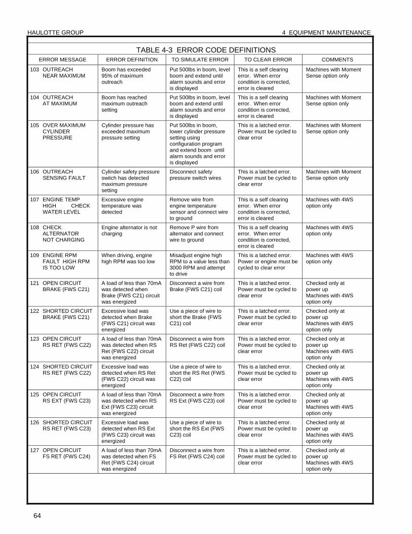
HAULOTTE GROUP 4 EQUIPMENT MAINTENANCE
64
TABLE 4-3 ERROR CODE DEFINITIONS ERROR MESSAGE ERROR DEFINITION TO SIMULATE ERROR TO CLEAR ERROR COMMENTS
103 OUTREACH NEAR MAXIMUM
Boom has exceeded 95% of maximum outreach
Put 500lbs in boom, level boom and extend until alarm sounds and error is displayed
This is a self clearing error. When error condition is corrected, error is cleared
Machines with Moment Sense option only
104 OUTREACH AT MAXIMUM
Boom has reached maximum outreach setting
Put 500lbs in boom, level boom and extend until alarm sounds and error is displayed
This is a self clearing error. When error condition is corrected, error is cleared
Machines with Moment Sense option only
105 OVER MAXIMUM CYLINDER PRESSURE
Cylinder pressure has exceeded maximum pressure setting
Put 500lbs in boom, lower cylinder pressure setting using configuration program and extend boom until alarm sounds and error is displayed
This is a latched error. Power must be cycled to clear error
Machines with Moment Sense option only
106 OUTREACH SENSING FAULT
Cylinder safety pressure switch has detected maximum pressure setting
Disconnect safety pressure switch wires
This is a latched error. Power must be cycled to clear error
Machines with Moment Sense option only
107 ENGINE TEMP HIGH CHECK WATER LEVEL
Excessive engine temperature was detected
Remove wire from engine temperature sensor and connect wire to ground
This is a self clearing error. When error condition is corrected, error is cleared
Machines with 4WS option only
108 CHECK ALTERNATOR NOT CHARGING
Engine alternator is not charging
Remove P wire from alternator and connect wire to ground
This is a self clearing error. When error condition is corrected, error is cleared
Machines with 4WS option only
109 ENGINE RPM FAULT HIGH RPM IS TOO LOW
When driving, engine high RPM was too low
Misadjust engine high RPM to a value less than 3000 RPM and attempt to drive
This is a latched error. Power or engine must be cycled to clear error
Machines with 4WS option only
121 OPEN CIRCUIT BRAKE (FWS C21)
A load of less than 70mA was detected when Brake (FWS C21) circuit was energized
Disconnect a wire from Brake (FWS C21) coil
This is a latched error. Power must be cycled to clear error
Checked only at power up Machines with 4WS option only
122 SHORTED CIRCUIT BRAKE (FWS C21)
Excessive load was detected when Brake (FWS C21) circuit was energized
Use a piece of wire to short the Brake (FWS C21) coil
This is a latched error. Power must be cycled to clear error
Checked only at power up Machines with 4WS option only
123 OPEN CIRCUIT RS RET (FWS C22)
A load of less than 70mA was detected when RS Ret (FWS C22) circuit was energized
Disconnect a wire from RS Ret (FWS C22) coil
This is a latched error. Power must be cycled to clear error
Checked only at power up Machines with 4WS option only
124 SHORTED CIRCUIT RS RET (FWS C22)
Excessive load was detected when RS Ret (FWS C22) circuit was energized
Use a piece of wire to short the RS Ret (FWS C22) coil
This is a latched error. Power must be cycled to clear error
Checked only at power up Machines with 4WS option only
125 OPEN CIRCUIT RS EXT (FWS C23)
A load of less than 70mA was detected when RS Ext (FWS C23) circuit was energized
Disconnect a wire from RS Ext (FWS C23) coil
This is a latched error. Power must be cycled to clear error
Checked only at power up Machines with 4WS option only
126 SHORTED CIRCUIT RS RET (FWS C23)
Excessive load was detected when RS Ext (FWS C23) circuit was energized
Use a piece of wire to short the RS Ext (FWS C23) coil
This is a latched error. Power must be cycled to clear error
Checked only at power up Machines with 4WS option only
127 OPEN CIRCUIT FS RET (FWS C24)
A load of less than 70mA was detected when FS Ret (FWS C24) circuit was energized
Disconnect a wire from FS Ret (FWS C24) coil
This is a latched error. Power must be cycled to clear error
Checked only at power up Machines with 4WS option only
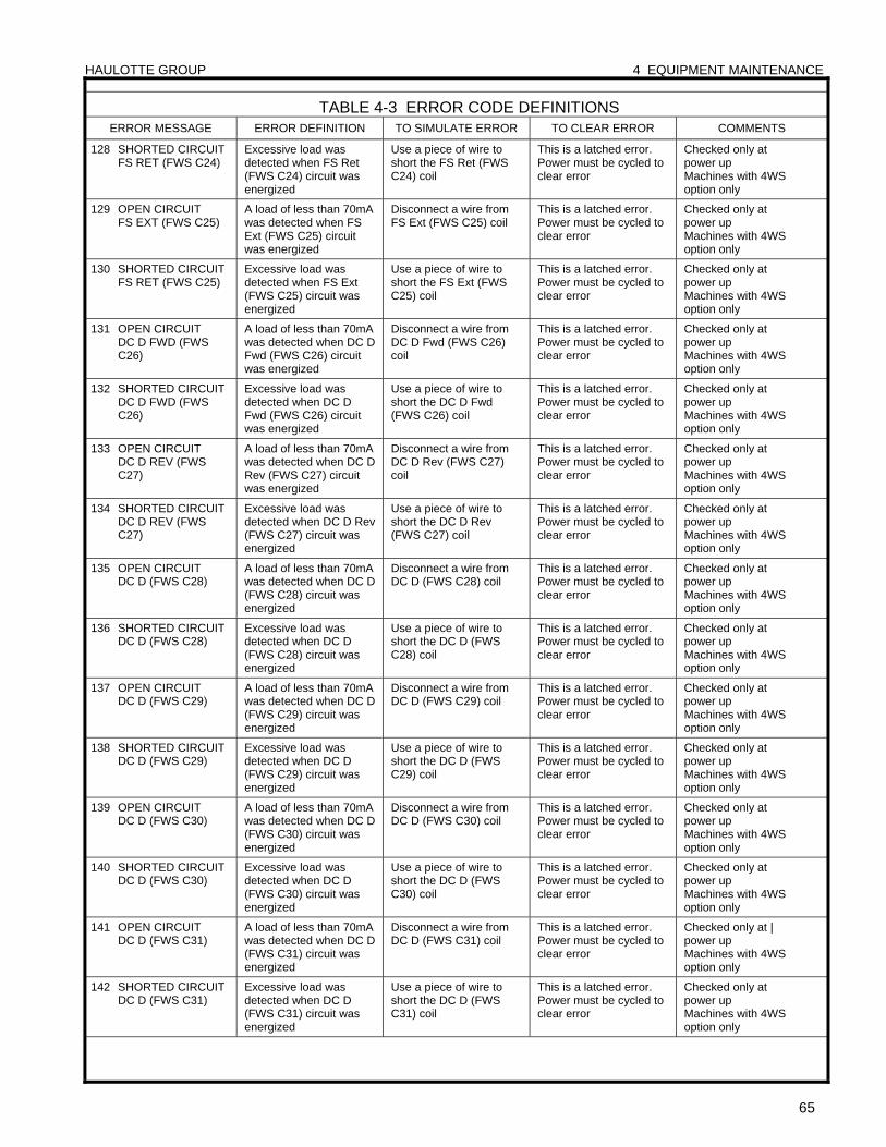
HAULOTTE GROUP 4 EQUIPMENT MAINTENANCE
65
TABLE 4-3 ERROR CODE DEFINITIONS ERROR MESSAGE ERROR DEFINITION TO SIMULATE ERROR TO CLEAR ERROR COMMENTS
128 SHORTED CIRCUIT FS RET (FWS C24)
Excessive load was detected when FS Ret (FWS C24) circuit was energized
Use a piece of wire to short the FS Ret (FWS C24) coil
This is a latched error. Power must be cycled to clear error
Checked only at power up Machines with 4WS option only
129 OPEN CIRCUIT FS EXT (FWS C25)
A load of less than 70mA was detected when FS Ext (FWS C25) circuit was energized
Disconnect a wire from FS Ext (FWS C25) coil
This is a latched error. Power must be cycled to clear error
Checked only at power up Machines with 4WS option only
130 SHORTED CIRCUIT FS RET (FWS C25)
Excessive load was detected when FS Ext (FWS C25) circuit was energized
Use a piece of wire to short the FS Ext (FWS C25) coil
This is a latched error. Power must be cycled to clear error
Checked only at power up Machines with 4WS option only
131 OPEN CIRCUIT DC D FWD (FWS C26)
A load of less than 70mA was detected when DC D Fwd (FWS C26) circuit was energized
Disconnect a wire from DC D Fwd (FWS C26) coil
This is a latched error. Power must be cycled to clear error
Checked only at power up Machines with 4WS option only
132 SHORTED CIRCUIT DC D FWD (FWS C26)
Excessive load was detected when DC D Fwd (FWS C26) circuit was energized
Use a piece of wire to short the DC D Fwd (FWS C26) coil
This is a latched error. Power must be cycled to clear error
Checked only at power up Machines with 4WS option only
133 OPEN CIRCUIT DC D REV (FWS C27)
A load of less than 70mA was detected when DC D Rev (FWS C27) circuit was energized
Disconnect a wire from DC D Rev (FWS C27) coil
This is a latched error. Power must be cycled to clear error
Checked only at power up Machines with 4WS option only
134 SHORTED CIRCUIT DC D REV (FWS C27)
Excessive load was detected when DC D Rev (FWS C27) circuit was energized
Use a piece of wire to short the DC D Rev (FWS C27) coil
This is a latched error. Power must be cycled to clear error
Checked only at power up Machines with 4WS option only
135 OPEN CIRCUIT DC D (FWS C28)
A load of less than 70mA was detected when DC D (FWS C28) circuit was energized
Disconnect a wire from DC D (FWS C28) coil
This is a latched error. Power must be cycled to clear error
Checked only at power up Machines with 4WS option only
136 SHORTED CIRCUIT DC D (FWS C28)
Excessive load was detected when DC D (FWS C28) circuit was energized
Use a piece of wire to short the DC D (FWS C28) coil
This is a latched error. Power must be cycled to clear error
Checked only at power up Machines with 4WS option only
137 OPEN CIRCUIT DC D (FWS C29)
A load of less than 70mA was detected when DC D (FWS C29) circuit was energized
Disconnect a wire from DC D (FWS C29) coil
This is a latched error. Power must be cycled to clear error
Checked only at power up Machines with 4WS option only
138 SHORTED CIRCUIT DC D (FWS C29)
Excessive load was detected when DC D (FWS C29) circuit was energized
Use a piece of wire to short the DC D (FWS C29) coil
This is a latched error. Power must be cycled to clear error
Checked only at power up Machines with 4WS option only
139 OPEN CIRCUIT DC D (FWS C30)
A load of less than 70mA was detected when DC D (FWS C30) circuit was energized
Disconnect a wire from DC D (FWS C30) coil
This is a latched error. Power must be cycled to clear error
Checked only at power up Machines with 4WS option only
140 SHORTED CIRCUIT DC D (FWS C30)
Excessive load was detected when DC D (FWS C30) circuit was energized
Use a piece of wire to short the DC D (FWS C30) coil
This is a latched error. Power must be cycled to clear error
Checked only at power up Machines with 4WS option only
141 OPEN CIRCUIT DC D (FWS C31)
A load of less than 70mA was detected when DC D (FWS C31) circuit was energized
Disconnect a wire from DC D (FWS C31) coil
This is a latched error. Power must be cycled to clear error
Checked only at | power up Machines with 4WS option only
142 SHORTED CIRCUIT DC D (FWS C31)
Excessive load was detected when DC D (FWS C31) circuit was energized
Use a piece of wire to short the DC D (FWS C31) coil
This is a latched error. Power must be cycled to clear error
Checked only at power up Machines with 4WS option only
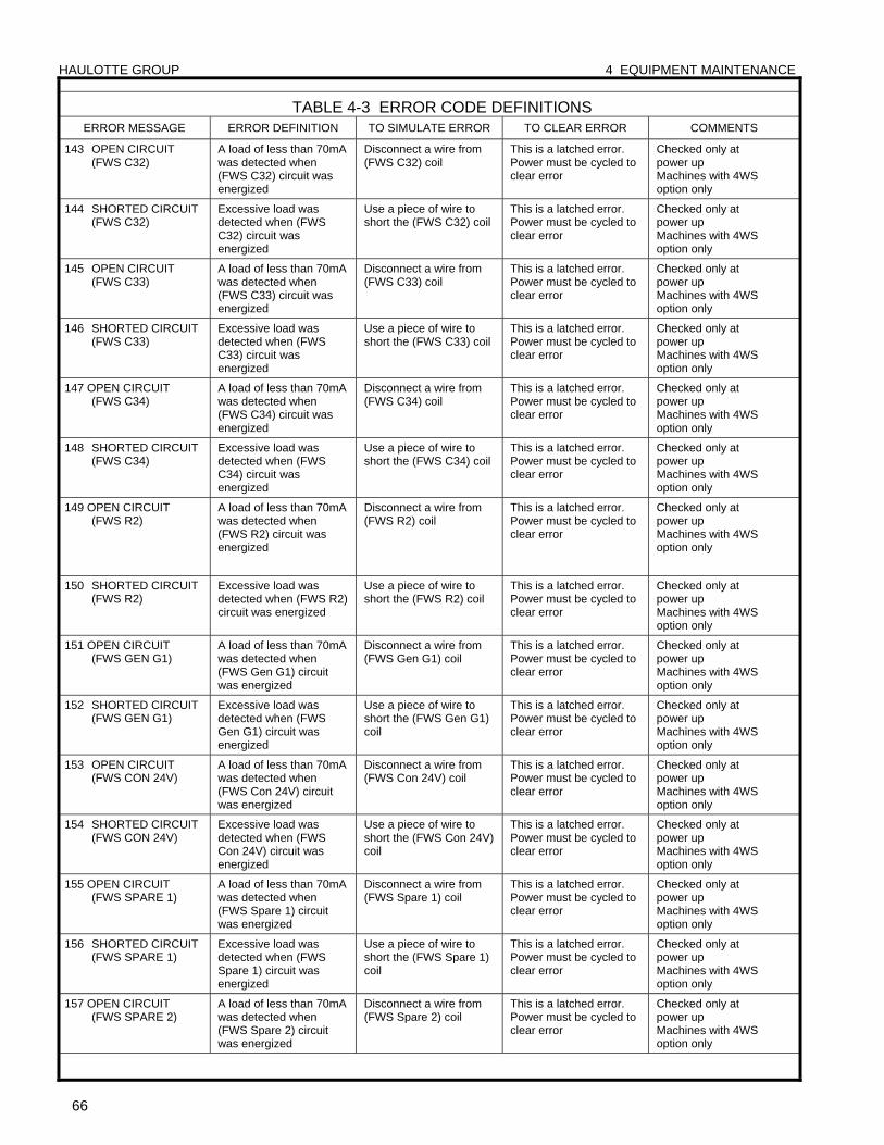
HAULOTTE GROUP 4 EQUIPMENT MAINTENANCE
66
TABLE 4-3 ERROR CODE DEFINITIONS ERROR MESSAGE ERROR DEFINITION TO SIMULATE ERROR TO CLEAR ERROR COMMENTS
143 OPEN CIRCUIT (FWS C32)
A load of less than 70mA was detected when (FWS C32) circuit was energized
Disconnect a wire from (FWS C32) coil
This is a latched error. Power must be cycled to clear error
Checked only at power up Machines with 4WS option only
144 SHORTED CIRCUIT (FWS C32)
Excessive load was detected when (FWS C32) circuit was energized
Use a piece of wire to short the (FWS C32) coil
This is a latched error. Power must be cycled to clear error
Checked only at power up Machines with 4WS option only
145 OPEN CIRCUIT (FWS C33)
A load of less than 70mA was detected when (FWS C33) circuit was energized
Disconnect a wire from (FWS C33) coil
This is a latched error. Power must be cycled to clear error
Checked only at power up Machines with 4WS option only
146 SHORTED CIRCUIT (FWS C33)
Excessive load was detected when (FWS C33) circuit was energized
Use a piece of wire to short the (FWS C33) coil
This is a latched error. Power must be cycled to clear error
Checked only at power up Machines with 4WS option only
147 OPEN CIRCUIT (FWS C34)
A load of less than 70mA was detected when (FWS C34) circuit was energized
Disconnect a wire from (FWS C34) coil
This is a latched error. Power must be cycled to clear error
Checked only at power up Machines with 4WS option only
148 SHORTED CIRCUIT (FWS C34)
Excessive load was detected when (FWS C34) circuit was energized
Use a piece of wire to short the (FWS C34) coil
This is a latched error. Power must be cycled to clear error
Checked only at power up Machines with 4WS option only
149 OPEN CIRCUIT (FWS R2)
A load of less than 70mA was detected when (FWS R2) circuit was energized
Disconnect a wire from (FWS R2) coil
This is a latched error. Power must be cycled to clear error
Checked only at power up Machines with 4WS option only
150 SHORTED CIRCUIT (FWS R2)
Excessive load was detected when (FWS R2) circuit was energized
Use a piece of wire to short the (FWS R2) coil
This is a latched error. Power must be cycled to clear error
Checked only at power up Machines with 4WS option only
151 OPEN CIRCUIT (FWS GEN G1)
A load of less than 70mA was detected when (FWS Gen G1) circuit was energized
Disconnect a wire from (FWS Gen G1) coil
This is a latched error. Power must be cycled to clear error
Checked only at power up Machines with 4WS option only
152 SHORTED CIRCUIT (FWS GEN G1)
Excessive load was detected when (FWS Gen G1) circuit was energized
Use a piece of wire to short the (FWS Gen G1) coil
This is a latched error. Power must be cycled to clear error
Checked only at power up Machines with 4WS option only
153 OPEN CIRCUIT (FWS CON 24V)
A load of less than 70mA was detected when (FWS Con 24V) circuit was energized
Disconnect a wire from (FWS Con 24V) coil
This is a latched error. Power must be cycled to clear error
Checked only at power up Machines with 4WS option only
154 SHORTED CIRCUIT (FWS CON 24V)
Excessive load was detected when (FWS Con 24V) circuit was energized
Use a piece of wire to short the (FWS Con 24V) coil
This is a latched error. Power must be cycled to clear error
Checked only at power up Machines with 4WS option only
155 OPEN CIRCUIT (FWS SPARE 1)
A load of less than 70mA was detected when (FWS Spare 1) circuit was energized
Disconnect a wire from (FWS Spare 1) coil
This is a latched error. Power must be cycled to clear error
Checked only at power up Machines with 4WS option only
156 SHORTED CIRCUIT (FWS SPARE 1)
Excessive load was detected when (FWS Spare 1) circuit was energized
Use a piece of wire to short the (FWS Spare 1) coil
This is a latched error. Power must be cycled to clear error
Checked only at power up Machines with 4WS option only
157 OPEN CIRCUIT (FWS SPARE 2)
A load of less than 70mA was detected when (FWS Spare 2) circuit was energized
Disconnect a wire from (FWS Spare 2) coil
This is a latched error. Power must be cycled to clear error
Checked only at power up Machines with 4WS option only
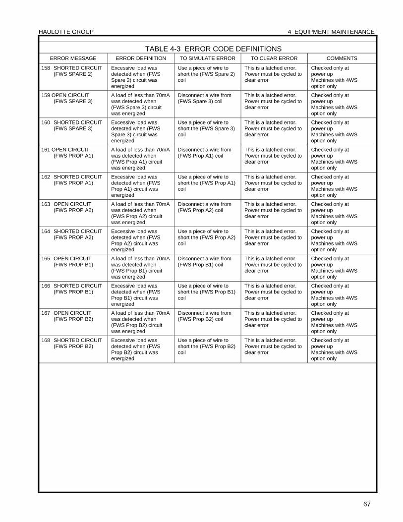
HAULOTTE GROUP 4 EQUIPMENT MAINTENANCE
67
TABLE 4-3 ERROR CODE DEFINITIONS ERROR MESSAGE ERROR DEFINITION TO SIMULATE ERROR TO CLEAR ERROR COMMENTS
158 SHORTED CIRCUIT (FWS SPARE 2)
Excessive load was detected when (FWS Spare 2) circuit was energized
Use a piece of wire to short the (FWS Spare 2) coil
This is a latched error. Power must be cycled to clear error
Checked only at power up Machines with 4WS option only
159 OPEN CIRCUIT (FWS SPARE 3)
A load of less than 70mA was detected when (FWS Spare 3) circuit was energized
Disconnect a wire from (FWS Spare 3) coil
This is a latched error. Power must be cycled to clear error
Checked only at power up Machines with 4WS option only
160 SHORTED CIRCUIT (FWS SPARE 3)
Excessive load was detected when (FWS Spare 3) circuit was energized
Use a piece of wire to short the (FWS Spare 3) coil
This is a latched error. Power must be cycled to clear error
Checked only at power up Machines with 4WS option only
161 OPEN CIRCUIT (FWS PROP A1)
A load of less than 70mA was detected when (FWS Prop A1) circuit was energized
Disconnect a wire from (FWS Prop A1) coil
This is a latched error. Power must be cycled to clear error
Checked only at power up Machines with 4WS option only
162 SHORTED CIRCUIT (FWS PROP A1)
Excessive load was detected when (FWS Prop A1) circuit was energized
Use a piece of wire to short the (FWS Prop A1) coil
This is a latched error. Power must be cycled to clear error
Checked only at power up Machines with 4WS option only
163 OPEN CIRCUIT (FWS PROP A2)
A load of less than 70mA was detected when (FWS Prop A2) circuit was energized
Disconnect a wire from (FWS Prop A2) coil
This is a latched error. Power must be cycled to clear error
Checked only at power up Machines with 4WS option only
164 SHORTED CIRCUIT (FWS PROP A2)
Excessive load was detected when (FWS Prop A2) circuit was energized
Use a piece of wire to short the (FWS Prop A2) coil
This is a latched error. Power must be cycled to clear error
Checked only at power up Machines with 4WS option only
165 OPEN CIRCUIT (FWS PROP B1)
A load of less than 70mA was detected when (FWS Prop B1) circuit was energized
Disconnect a wire from (FWS Prop B1) coil
This is a latched error. Power must be cycled to clear error
Checked only at power up Machines with 4WS option only
166 SHORTED CIRCUIT (FWS PROP B1)
Excessive load was detected when (FWS Prop B1) circuit was energized
Use a piece of wire to short the (FWS Prop B1) coil
This is a latched error. Power must be cycled to clear error
Checked only at power up Machines with 4WS option only
167 OPEN CIRCUIT (FWS PROP B2)
A load of less than 70mA was detected when (FWS Prop B2) circuit was energized
Disconnect a wire from (FWS Prop B2) coil
This is a latched error. Power must be cycled to clear error
Checked only at power up Machines with 4WS option only
168 SHORTED CIRCUIT (FWS PROP B2)
Excessive load was detected when (FWS Prop B2) circuit was energized
Use a piece of wire to short the (FWS Prop B2) coil
This is a latched error. Power must be cycled to clear error
Checked only at power up Machines with 4WS option only
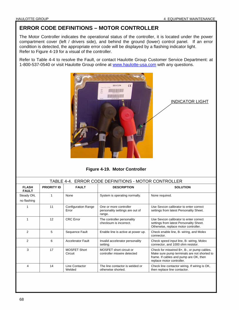
HAULOTTE GROUP 4 EQUIPMENT MAINTENANCE
68
ERROR CODE DEFINITIONS – MOTOR CONTROLLER
The Motor Controller indicates the operational status of the controller, it is located under the power compartment cover (left / drivers side), and behind the ground (lower) control panel. If an error condition is detected, the appropriate error code will be displayed by a flashing indicator light. Refer to Figure 4-19 for a visual of the controller.
Refer to Table 4-4 to resolve the Fault, or contact Haulotte Group Customer Service Department: at 1-800-537-0540 or visit Haulotte Group online at www.haulotte-usa.com with any questions.
Figure 4-19. Motor Controller
TABLE 4-4. ERROR CODE DEFINITIONS - MOTOR CONTROLLER FLASH FAULT
PRIORITY ID FAULT DESCRIPTION SOLUTION
Steady ON,
no flashing
1 None System is operating normally. None required.
1 11 Configuration Range Error
One or more controller personality settings are out of range.
Use Sevcon calibrator to enter correct settings from latest Personality Sheet.
1 12 CRC Error The controller personality checksum is incorrect.
Use Sevcon calibrator to enter correct settings from latest Personality Sheet. Otherwise, replace motor controller.
2 5 Sequence Fault Enable line is active at power up. Check enable line, B- wiring, and Molex connector.
2 6 Accelerator Fault Invalid accelerator personality setting.
Check speed input line, B- wiring, Molex connector, and 1000 ohm resistor.
3 17 MOSFET Short Circuit
MOSFET short circuit or controller miswire detected
Check for miswired B+, B-, or pump cables. Make sure pump terminals are not shorted to frame. If cables and pump are OK, then replace motor controller.
4 14 Line Contactor Welded
The line contactor is welded or otherwise shorted.
Check line contactor wiring. If wiring is OK, then replace line contactor.
INDICATOR LIGHT
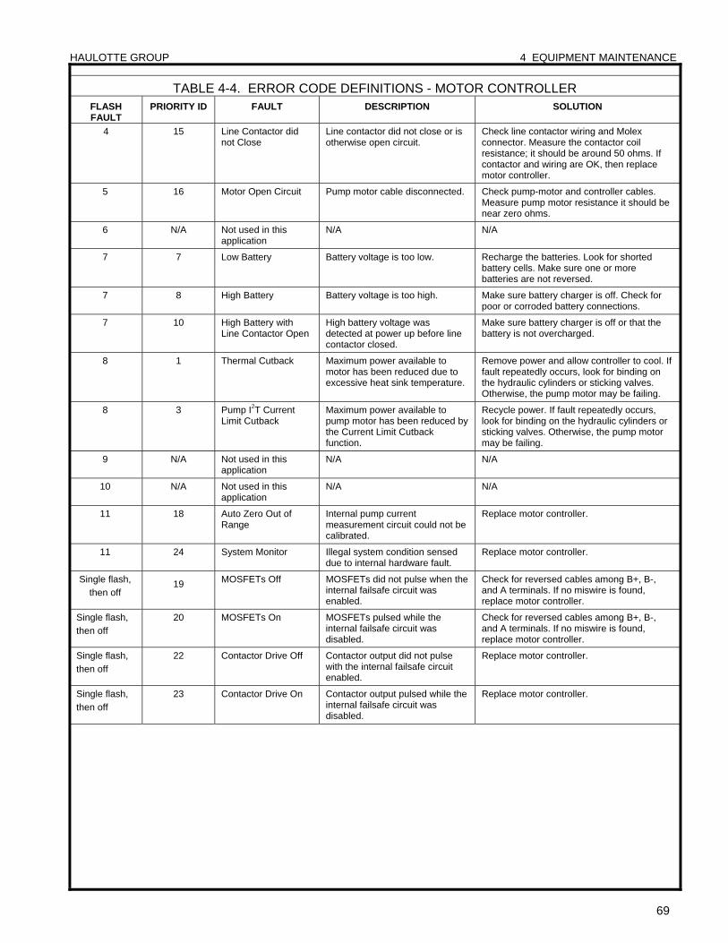
HAULOTTE GROUP 4 EQUIPMENT MAINTENANCE
69
TABLE 4-4. ERROR CODE DEFINITIONS - MOTOR CONTROLLER FLASH FAULT
PRIORITY ID FAULT DESCRIPTION SOLUTION
4 15 Line Contactor did not Close
Line contactor did not close or is otherwise open circuit.
Check line contactor wiring and Molex connector. Measure the contactor coil resistance; it should be around 50 ohms. If contactor and wiring are OK, then replace motor controller.
5 16 Motor Open Circuit Pump motor cable disconnected. Check pump-motor and controller cables. Measure pump motor resistance it should be near zero ohms.
6 N/A Not used in this application
N/A N/A
7 7 Low Battery Battery voltage is too low. Recharge the batteries. Look for shorted battery cells. Make sure one or more batteries are not reversed.
7 8 High Battery Battery voltage is too high. Make sure battery charger is off. Check for poor or corroded battery connections.
7 10 High Battery with Line Contactor Open
High battery voltage was detected at power up before line contactor closed.
Make sure battery charger is off or that the battery is not overcharged.
8 1 Thermal Cutback Maximum power available to motor has been reduced due to excessive heat sink temperature.
Remove power and allow controller to cool. If fault repeatedly occurs, look for binding on the hydraulic cylinders or sticking valves. Otherwise, the pump motor may be failing.
8 3 Pump I2T Current Limit Cutback
Maximum power available to pump motor has been reduced by the Current Limit Cutback function.
Recycle power. If fault repeatedly occurs, look for binding on the hydraulic cylinders or sticking valves. Otherwise, the pump motor may be failing.
9 N/A Not used in this application
N/A N/A
10 N/A Not used in this application
N/A N/A
11 18 Auto Zero Out of Range
Internal pump current measurement circuit could not be calibrated.
Replace motor controller.
11 24 System Monitor Illegal system condition sensed due to internal hardware fault.
Replace motor controller.
Single flash,
then off 19 MOSFETs Off MOSFETs did not pulse when the
internal failsafe circuit was enabled.
Check for reversed cables among B+, B-, and A terminals. If no miswire is found, replace motor controller.
Single flash,
then off
20 MOSFETs On MOSFETs pulsed while the internal failsafe circuit was disabled.
Check for reversed cables among B+, B-, and A terminals. If no miswire is found, replace motor controller.
Single flash,
then off
22 Contactor Drive Off Contactor output did not pulse with the internal failsafe circuit enabled.
Replace motor controller.
Single flash,
then off
23 Contactor Drive On Contactor output pulsed while the internal failsafe circuit was disabled.
Replace motor controller.

HAULOTTE GROUP 5 CYLINDER REPLACEMENT
70
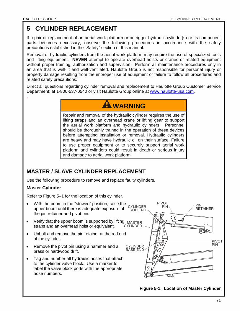
HAULOTTE GROUP 5 CYLINDER REPLACEMENT
71
PIVOT PIN
CYLINDER ROD END
CYLINDER BASE END
MASTER CYLINDER
PIVOT PIN PIN
RETAINER
5 CYLINDER REPLACEMENT
If repair or replacement of an aerial work platform or outrigger hydraulic cylinder(s) or its component parts becomes necessary, observe the following procedures in accordance with the safety precautions established in the “Safety” section of this manual.
Removal of hydraulic cylinders from the aerial work platform may require the use of specialized tools and lifting equipment. NEVER attempt to operate overhead hoists or cranes or related equipment without proper training, authorization and supervision. Perform all maintenance procedures only in an area that is well-lit and well-ventilated. Haulotte Group is not responsible for personal injury or property damage resulting from the improper use of equipment or failure to follow all procedures and related safety precautions.
Direct all questions regarding cylinder removal and replacement to Haulotte Group Customer Service Department: at 1-800-537-0540 or visit Haulotte Group online at www.haulotte-usa.com. .
MASTER / SLAVE CYLINDER REPLACEMENT
Use the following procedure to remove and replace faulty cylinders.
Master Cylinder
Refer to Figure 5–1 for the location of this cylinder.
With the boom in the “stowed” position, raise the upper boom until there is adequate exposure of the pin retainer and pivot pin.
Verify that the upper boom is supported by lifting straps and an overhead hoist or equivalent.
Unbolt and remove the pin retainer at the rod end of the cylinder.
Remove the pivot pin using a hammer and a brass or hardwood drift.
Tag and number all hydraulic hoses that attach to the cylinder valve block. Use a marker to label the valve block ports with the appropriate hose numbers.
Figure 5-1. Location of Master Cylinder
WARNING Repair and removal of the hydraulic cylinder requires the use of lifting straps and an overhead crane or lifting gear to support the aerial work platform and hydraulic cylinders. Personnel should be thoroughly trained in the operation of these devices before attempting installation or removal. Hydraulic cylinders are heavy and may have hydraulic oil on their surface. Failure to use proper equipment or to securely support aerial work platform and cylinders could result in death or serious injury and damage to aerial work platform.
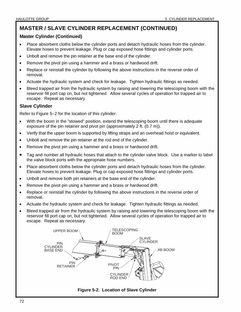
HAULOTTE GROUP 5 CYLINDER REPLACEMENT
72
TELESCOPING BOOM
BASE END CYLINDER
RETAINER PIN
CYLINDER SLAVE
ROD END
UPPER BOOM
JIB BOOM
CYLINDER
PIN
PIVOT PIN
MASTER / SLAVE CYLINDER REPLACEMENT (CONTINUED)
Master Cylinder (Continued)
Place absorbent cloths below the cylinder ports and detach hydraulic hoses from the cylinder. Elevate hoses to prevent leakage. Plug or cap exposed hose fittings and cylinder ports.
Unbolt and remove the pin retainer at the base end of the cylinder.
Remove the pivot pin using a hammer and a brass or hardwood drift.
Replace or reinstall the cylinder by following the above instructions in the reverse order of removal.
Actuate the hydraulic system and check for leakage. Tighten hydraulic fittings as needed.
Bleed trapped air from the hydraulic system by raising and lowering the telescoping boom with the reservoir fill port cap on, but not tightened. Allow several cycles of operation for trapped air to escape. Repeat as necessary.
Slave Cylinder
Refer to Figure 5–2 for the location of this cylinder.
With the boom in the “stowed” position, extend the telescoping boom until there is adequate exposure of the pin retainer and pivot pin (approximately 2 ft. (0.7 m)).
Verify that the upper boom is supported by lifting straps and an overhead hoist or equivalent.
Unbolt and remove the pin retainer at the rod end of the cylinder.
Remove the pivot pin using a hammer and a brass or hardwood drift.
Tag and number all hydraulic hoses that attach to the cylinder valve block. Use a marker to label the valve block ports with the appropriate hose numbers.
Place absorbent cloths below the cylinder ports and detach hydraulic hoses from the cylinder. Elevate hoses to prevent leakage. Plug or cap exposed hose fittings and cylinder ports.
Unbolt and remove both pin retainers at the base end of the cylinder.
Remove the pivot pin using a hammer and a brass or hardwood drift.
Replace or reinstall the cylinder by following the above instructions in the reverse order of removal.
Actuate the hydraulic system and check for leakage. Tighten hydraulic fittings as needed.
Bleed trapped air from the hydraulic system by raising and lowering the telescoping boom with the reservoir fill port cap on, but not tightened. Allow several cycles of operation for trapped air to escape. Repeat as necessary.
Figure 5-2. Location of Slave Cylinder
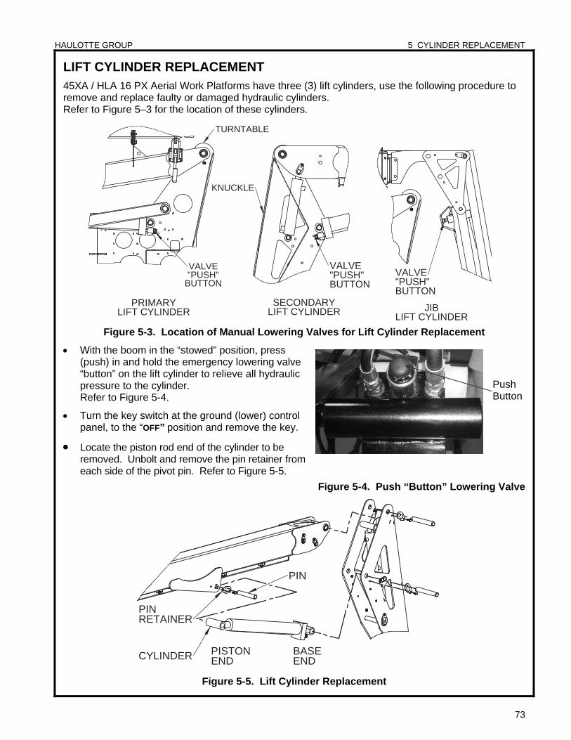
HAULOTTE GROUP 5 CYLINDER REPLACEMENT
73
PRIMARYLIFT CYLINDER
TURNTABLE
VALVE"PUSH"
BUTTON
LIFT CYLINDERSECONDARY
KNUCKLE
VALVE"PUSH"BUTTON
VALVE"PUSH"BUTTON
JIBLIFT CYLINDER
PISTONEND
RETAINER
PIN
PIN
CYLINDER BASEEND
LIFT CYLINDER REPLACEMENT 45XA / HLA 16 PX Aerial Work Platforms have three (3) lift cylinders, use the following procedure to remove and replace faulty or damaged hydraulic cylinders. Refer to Figure 5–3 for the location of these cylinders.
Figure 5-3. Location of Manual Lowering Valves for Lift Cylinder Replacement
With the boom in the “stowed” position, press (push) in and hold the emergency lowering valve “button” on the lift cylinder to relieve all hydraulic pressure to the cylinder. Refer to Figure 5-4.
Turn the key switch at the ground (lower) control panel, to the “OFF” position and remove the key.
Locate the piston rod end of the cylinder to be removed. Unbolt and remove the pin retainer from each side of the pivot pin. Refer to Figure 5-5.
Figure 5-4. Push “Button” Lowering Valve
Figure 5-5. Lift Cylinder Replacement
Push Button
HAULOTTE GROUP 5 CYLINDER REPLACEMENT
74
LIFT CYLINDER REPLACEMENT (CONTINUED)
Verify that the cylinder is supported by lifting straps and an overhead hoist or equivalent.
Remove the pivot pin using a hammer and a brass or hardwood drift.
Use an overhead crane or lifting gear to raise the boom section. Adequate clearance is necessary to reach the cylinder valve block (base end) and hydraulic hose ports.
Remove the valve solenoid by unscrewing the cap, sliding the coil off, then unscrewing the valve.
Tag and number all hydraulic hoses that attach to the cylinder valve block. Use a marker to label the valve block ports with the appropriate hose numbers.
Place absorbent cloths below the cylinder ports and detach hydraulic hoses from the cylinder. Elevate hoses to prevent leakage. Plug or cap exposed hose fittings and cylinder ports.
At the base of the cylinder, unbolt and remove the pin retainer from each side of the pivot pin.
Remove the pivot pin using a hammer and a brass or hardwood drift.
Lift and remove the cylinder using an overhead hoist and lifting straps or equivalent.
Replace or reinstall the cylinder by following the above instructions in the reverse order of removal.
Actuate the hydraulic system and check for leakage. Tighten hydraulic fittings as needed.
Bleed trapped air from the hydraulic system by raising and lowering the boom with the reservoir fill port cap on, but not tightened. Allow several cycles of operation for trapped air to escape. Repeat as necessary.
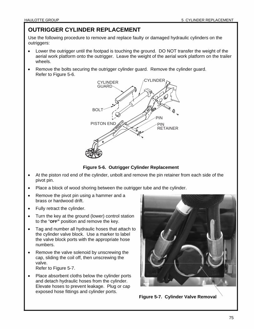
HAULOTTE GROUP 5 CYLINDER REPLACEMENT
75
PIN
CYLINDERGUARD
CYLINDER
PINRETAINER
PISTON END
BOLT
OUTRIGGER CYLINDER REPLACEMENT Use the following procedure to remove and replace faulty or damaged hydraulic cylinders on the outriggers:
Lower the outrigger until the footpad is touching the ground. DO NOT transfer the weight of the aerial work platform onto the outrigger. Leave the weight of the aerial work platform on the trailer wheels.
Remove the bolts securing the outrigger cylinder guard. Remove the cylinder guard. Refer to Figure 5-6.
Figure 5-6. Outrigger Cylinder Replacement
At the piston rod end of the cylinder, unbolt and remove the pin retainer from each side of the pivot pin.
Place a block of wood shoring between the outrigger tube and the cylinder.
Remove the pivot pin using a hammer and a brass or hardwood drift.
Fully retract the cylinder.
Turn the key at the ground (lower) control station to the “OFF” position and remove the key.
Tag and number all hydraulic hoses that attach to the cylinder valve block. Use a marker to label the valve block ports with the appropriate hose numbers.
Remove the valve solenoid by unscrewing the cap, sliding the coil off, then unscrewing the valve. Refer to Figure 5-7.
Place absorbent cloths below the cylinder ports and detach hydraulic hoses from the cylinder. Elevate hoses to prevent leakage. Plug or cap exposed hose fittings and cylinder ports.
Figure 5-7. Cylinder Valve Removal
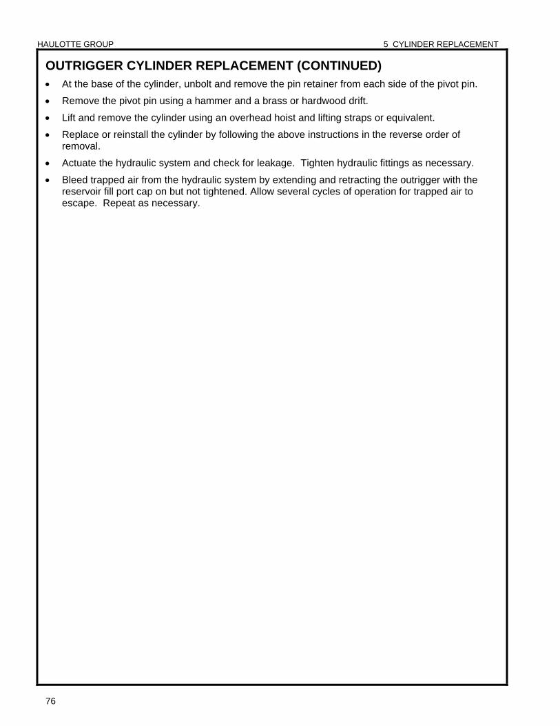
HAULOTTE GROUP 5 CYLINDER REPLACEMENT
76
OUTRIGGER CYLINDER REPLACEMENT (CONTINUED) At the base of the cylinder, unbolt and remove the pin retainer from each side of the pivot pin.
Remove the pivot pin using a hammer and a brass or hardwood drift.
Lift and remove the cylinder using an overhead hoist and lifting straps or equivalent.
Replace or reinstall the cylinder by following the above instructions in the reverse order of removal.
Actuate the hydraulic system and check for leakage. Tighten hydraulic fittings as necessary.
Bleed trapped air from the hydraulic system by extending and retracting the outrigger with the reservoir fill port cap on but not tightened. Allow several cycles of operation for trapped air to escape. Repeat as necessary.
HAULOTTE GROUP 6 DECAL REPLACEMENT
77
6 DECAL REPLACEMENT
WARNING Decals contain information that is required for the safe and proper use of the aerial work platform.
Decals should be considered necessary components of the machine and should be checked before each use to verify that they are correctly attached and legible.
Promptly replace all decals that are no longer legible.
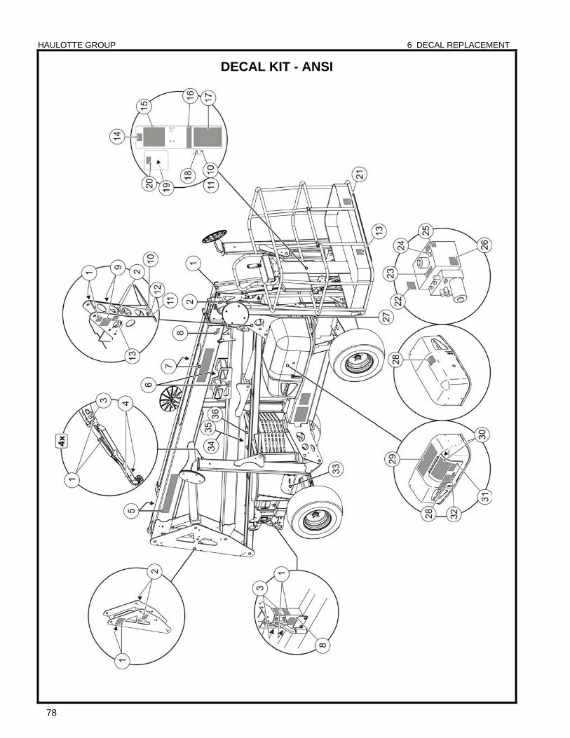
HAULOTTE GROUP 6 DECAL REPLACEMENT
78
DECAL KIT - ANSI
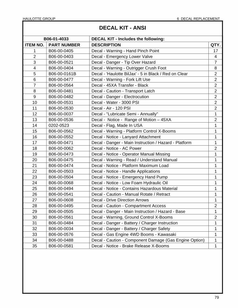
HAULOTTE GROUP 6 DECAL REPLACEMENT
79
DECAL KIT - ANSI
B06-01-4033 DECAL KIT - Includes the following:
ITEM NO. PART NUMBER DESCRIPTION QTY.1 B06-00-0405 Decal - Warning - Hand Pinch Point 17 2 B06-00-0403 Decal - Emergency Lower Valve 4 3 B06-00-0521 Decal - Danger - Tip Over Hazard 7 4 B06-00-0404 Decal - Warning - Outrigger Crush Foot 8 5 B06-00-0161B Decal - 'Haulotte BilJax' - 5 in Black / Red on Clear 2 6 B06-00-0477 Decal - Warning - Fork Lift Use 2 7 B06-00-0564 Decal - 45XA Transfer - Black 2 8 B06-00-0481 Decal - Caution - Transport Latch 2 9 B06-00-0482 Decal - Danger - Electrocution 2
10 B06-00-0531 Decal - Water - 3000 PSI 2 11 B06-00-0530 Decal - Air - 120 PSI 2 12 B06-00-0037 Decal - "Lubricate Semi - Annually" 1 13 B06-00-0536 Decal - Notice - Range of Motion – 45XA 2 14 0202-0523 Decal - Flag, Made In USA 1 15 B06-00-0562 Decal - Warning - Platform Control X-Booms 1 16 B06-00-0552 Decal - Notice - Lanyard Attachment 1 17 B06-00-0471 Decal - Danger - Main Instruction / Hazard - Platform 1 18 B06-00-0062 Decal - Notice - AC Power 2 19 B06-00-0473 Decal - Notice - Operator Manual Missing 1 20 B06-00-0475 Decal - Warning - Read / Understand Manual 1 21 B06-00-0474 Decal - Notice - Platform Maximum Load 1 22 B06-00-0503 Decal - Notice - Handle Applications 1 23 B06-00-0504 Decal - Notice - Emergency Hand Pump 1 24 B06-00-0068 Decal - Notice - Low Foam Hydraulic Oil 1 25 B06-00-0494 Decal - Notice - Contains Hazardous Material 1 26 B06-00-0541 Decal - Caution - Manual Rotate / Retract 1 27 B06-00-0608 Decal - Drive Direction Arrows 1 28 B06-00-0495 Decal - Caution - Compartment Access 2 29 B06-00-0505 Decal - Danger - Main Instruction / Hazard - Base 1 30 B06-00-0561 Decal - Warning, Ground Control X-Booms 2 31 B06-00-0484 Decal - Danger - Battery / Charger Instruction 1 32 B06-00-0034 Decal - Danger - Battery / Charger Safety 1 33 B06-00-0576 Decal - Gas Engine 4WD Booms - Kawasaki 1 34 B06-00-0488 Decal - Caution - Component Damage (Gas Engine Option) 1 35 B06-00-0581 Decal - Notice - Brake Release X-Booms 1
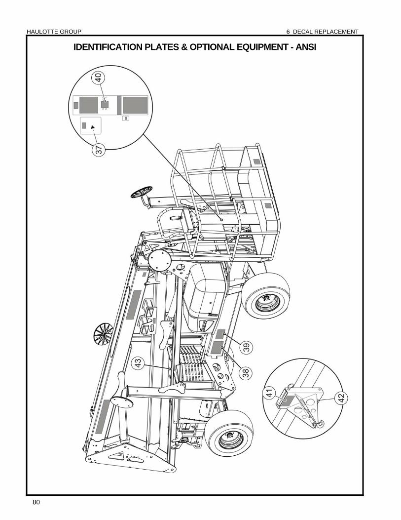
HAULOTTE GROUP 6 DECAL REPLACEMENT
80
IDENTIFICATION PLATES & OPTIONAL EQUIPMENT - ANSI
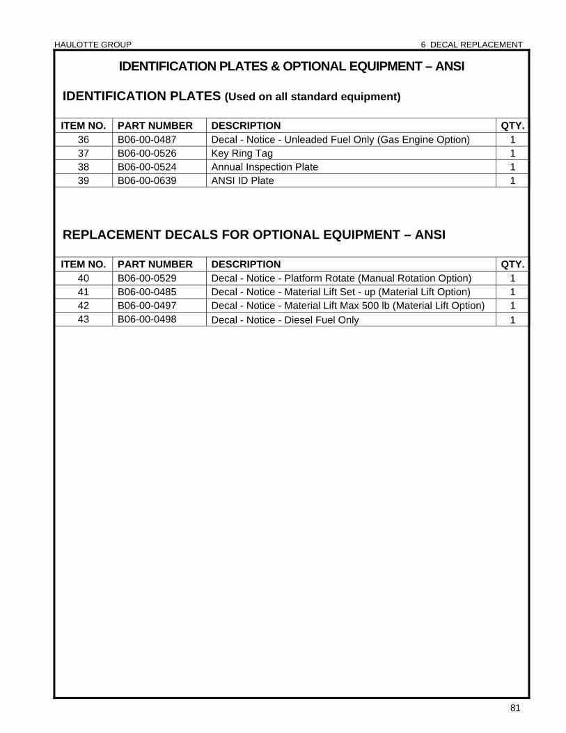
HAULOTTE GROUP 6 DECAL REPLACEMENT
81
IDENTIFICATION PLATES & OPTIONAL EQUIPMENT – ANSI
IDENTIFICATION PLATES (Used on all standard equipment)
ITEM NO. PART NUMBER DESCRIPTION QTY.36 B06-00-0487 Decal - Notice - Unleaded Fuel Only (Gas Engine Option) 1 37 B06-00-0526 Key Ring Tag 1 38 B06-00-0524 Annual Inspection Plate 1 39 B06-00-0639 ANSI ID Plate 1
REPLACEMENT DECALS FOR OPTIONAL EQUIPMENT – ANSI ITEM NO. PART NUMBER DESCRIPTION QTY.
40 B06-00-0529 Decal - Notice - Platform Rotate (Manual Rotation Option) 1 41 B06-00-0485 Decal - Notice - Material Lift Set - up (Material Lift Option) 1 42 B06-00-0497 Decal - Notice - Material Lift Max 500 lb (Material Lift Option) 1 43 B06-00-0498 Decal - Notice - Diesel Fuel Only 1
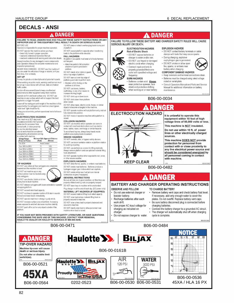
HAULOTTE GROUP 6 DECAL REPLACEMENT
82
DECALS - ANSI
0202-0523
B06-00-0161B
B06-00-0530 B06-00-0531
B06-00-0484
B06-00-0034
B06-00-0482
B06-00-0521
B06-00-0564
B06-00-0471
B06-00-0536 45XA / HLA 16 PX
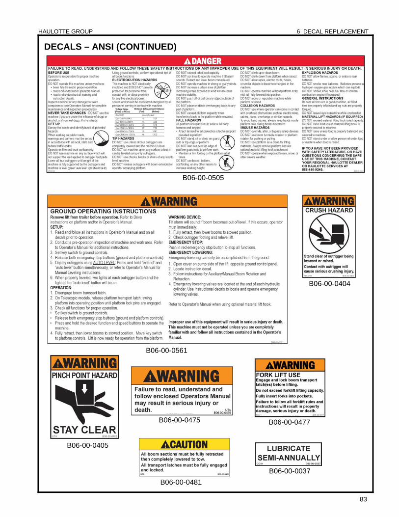
HAULOTTE GROUP 6 DECAL REPLACEMENT
83
DECALS – ANSI (CONTINUED)
B06-00-0037
B06-00-0404
B06-00-0475
B06-00-0405
B06-00-0481
B06-00-0477
B06-00-0561
B06-00-0505

HAULOTTE GROUP 6 DECAL REPLACEMENT
84
DECALS – ANSI (CONTINUED)
B06-00-0552
B06-00-0495
B06-00-0504
B06-00-0488
B06-00-0562
B06-00-0544B06-00-0581
B06-00-0608B06-00-0541
B06-00-0639
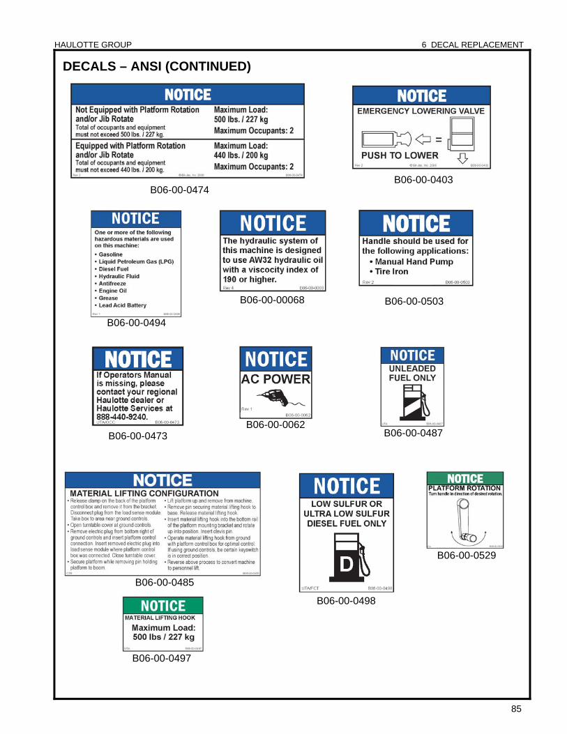
HAULOTTE GROUP 6 DECAL REPLACEMENT
85
DECALS – ANSI (CONTINUED)
B06-00-0487
B06-00-0485
B06-00-0062
B06-00-0497
B06-00-00068
B06-00-0403
B06-00-0473
B06-00-0529
B06-00-0494
B06-00-0498
B06-00-0503
B06-00-0474

HAULOTTE GROUP 6 DECAL REPLACEMENT
86
HAULOTTE GROUP 7 OPTIONAL EQUIPMENT
87
7 OPTIONAL EQUIPMENT The Haulotte Model 45XA / HLA 16 PX is a Self-Propelled aerial work platform that may be may be equipped with one or more optional components designed for the convenience and safety of operators when using the equipment to accomplish specific tasks.
Always use only those components manufactured and / or authorized by Haulotte Group. Never make any adjustments or modifications or otherwise alter the equipment in any way that is not expressly recommended by the manufacturer.
When operating an aerial work platform equipped with optional components, observe all safety precautions set forth by the manufacturer, as well as all Government codes and regulations regarding this equipment and its components.
Consult rental agency or manufacturer regarding which optional components may be installed on the aerial work platform. For questions regarding safe use, contact Haulotte Group Customer Service Department: at 1-800-537-0540 or visit Haulotte Group online at www.haulotte-usa.com.
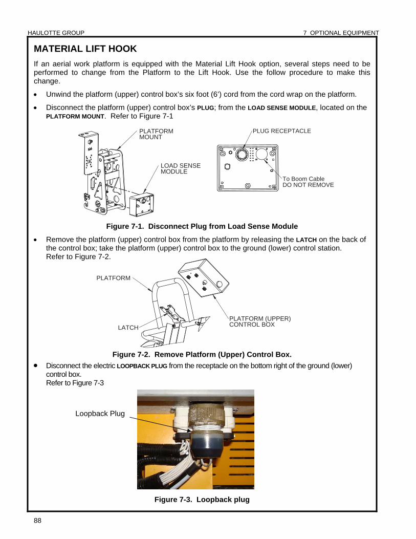
HAULOTTE GROUP 7 OPTIONAL EQUIPMENT
88
LATCH
PLATFORM
PLATFORM (UPPER)CONTROL BOX
DO NOT REMOVETo Boom Cable
PLUG RECEPTACLE
LOAD SENSE MODULE
PLATFORM MOUNT
MATERIAL LIFT HOOK
If an aerial work platform is equipped with the Material Lift Hook option, several steps need to be performed to change from the Platform to the Lift Hook. Use the follow procedure to make this change.
Unwind the platform (upper) control box’s six foot (6’) cord from the cord wrap on the platform.
Disconnect the platform (upper) control box’s PLUG; from the LOAD SENSE MODULE, located on the PLATFORM MOUNT. Refer to Figure 7-1
Figure 7-1. Disconnect Plug from Load Sense Module
Remove the platform (upper) control box from the platform by releasing the LATCH on the back of the control box; take the platform (upper) control box to the ground (lower) control station. Refer to Figure 7-2.
Figure 7-2. Remove Platform (Upper) Control Box.
Disconnect the electric LOOPBACK PLUG from the receptacle on the bottom right of the ground (lower) control box. Refer to Figure 7-3
Figure 7-3. Loopback plug
Loopback Plug
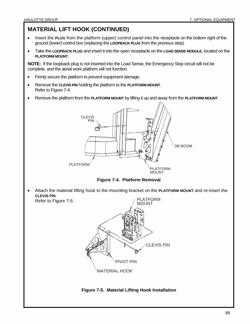
HAULOTTE GROUP 7 OPTIONAL EQUIPMENT
89
PLATFORMPLATFORMMOUNT
JIB BOOM
CLEVIS PIN
MATERIAL HOOK
CLEVIS PIN
PIVOT PIN
PLATFORM MOUNT
MATERIAL LIFT HOOK (CONTINUED)
Insert the PLUG from the platform (upper) control panel into the receptacle on the bottom right of the ground (lower) control box (replacing the LOOPBACK PLUG from the previous step).
Take the LOOPBACK PLUG and insert it into the open receptacle on the LOAD SENSE MODULE, located on the PLATFORM MOUNT.
NOTE: If the loopback plug is not inserted into the Load Sense, the Emergency Stop circuit will not be complete, and the aerial work platform will not function.
Firmly secure the platform to prevent equipment damage.
Remove the CLEVIS PIN holding the platform to the PLATFORM MOUNT. Refer to Figure 7-4.
Remove the platform from the PLATFORM MOUNT by lifting it up and away from the PLATFORM MOUNT.
Figure 7-4. Platform Removal
Attach the material lifting hook to the mounting bracket on the PLATFORM MOUNT and re-insert the
CLEVIS PIN. Refer to Figure 7-5.
Figure 7-5. Material Lifting Hook Installation
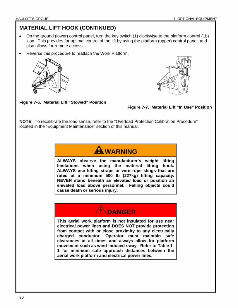
HAULOTTE GROUP 7 OPTIONAL EQUIPMENT
90
MATERIAL LIFT HOOK (CONTINUED)
On the ground (lower) control panel, turn the key switch (1) clockwise to the platform control (1b) icon. This provides for optimal control of the lift by using the platform (upper) control panel, and also allows for remote access.
Reverse this procedure to reattach the Work Platform.
Figure 7-6. Material Lift “Stowed” Position Figure 7-7. Material Lift “In Use” Position
NOTE: To recalibrate the load sense, refer to the “Overload Protection Calibration Procedure” located in the “Equipment Maintenance” section of this manual.
WARNING ALWAYS observe the manufacturer’s weight lifting limitations when using the material lifting hook. ALWAYS use lifting straps or wire rope slings that are rated at a minimum 500 lb (227kg) lifting capacity. NEVER stand beneath an elevated load or position an elevated load above personnel. Falling objects could cause death or serious injury.
DANGER This aerial work platform is not insulated for use near electrical power lines and DOES NOT provide protection from contact with or close proximity to any electrically charged conductor. Operator must maintain safe clearances at all times and always allow for platform movement such as wind-induced sway. Refer to Table 1-1 for minimum safe approach distances between the aerial work platform and electrical power lines.
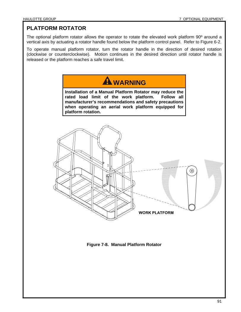
HAULOTTE GROUP 7 OPTIONAL EQUIPMENT
91
PLATFORM ROTATOR
The optional platform rotator allows the operator to rotate the elevated work platform 90º around a vertical axis by actuating a rotator handle found below the platform control panel. Refer to Figure 6-2.
To operate manual platform rotator, turn the rotator handle in the direction of desired rotation (clockwise or counterclockwise). Motion continues in the desired direction until rotator handle is released or the platform reaches a safe travel limit.
Figure 7-8. Manual Platform Rotator
WARNING Installation of a Manual Platform Rotator may reduce the rated load limit of the work platform. Follow all manufacturer’s recommendations and safety precautions when operating an aerial work platform equipped for platform rotation.

HAULOTTE GROUP 7 OPTIONAL EQUIPMENT
92
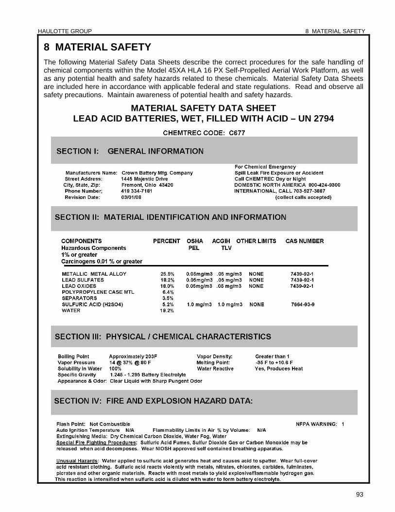
HAULOTTE GROUP 8 MATERIAL SAFETY
93
8 MATERIAL SAFETY The following Material Safety Data Sheets describe the correct procedures for the safe handling of chemical components within the Model 45XA HLA 16 PX Self-Propelled Aerial Work Platform, as well as any potential health and safety hazards related to these chemicals. Material Safety Data Sheets are included here in accordance with applicable federal and state regulations. Read and observe all safety precautions. Maintain awareness of potential health and safety hazards.
MATERIAL SAFETY DATA SHEET LEAD ACID BATTERIES, WET, FILLED WITH ACID – UN 2794
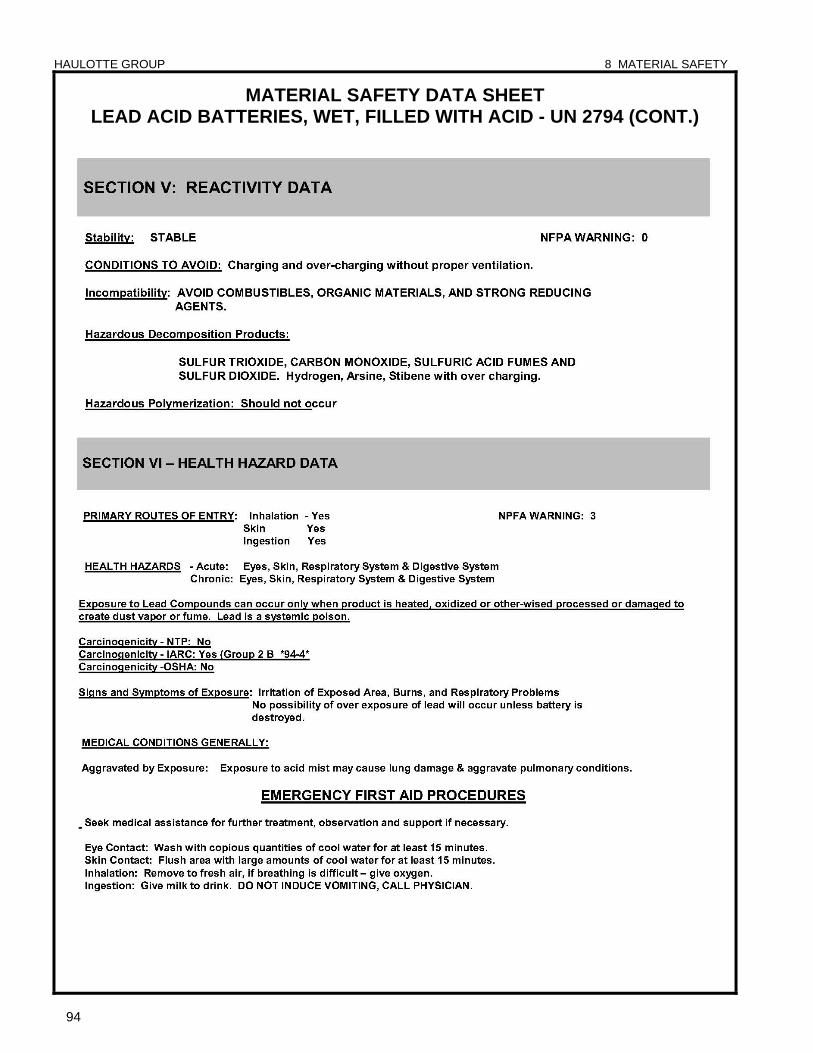
HAULOTTE GROUP 8 MATERIAL SAFETY
94
MATERIAL SAFETY DATA SHEET LEAD ACID BATTERIES, WET, FILLED WITH ACID - UN 2794 (CONT.)
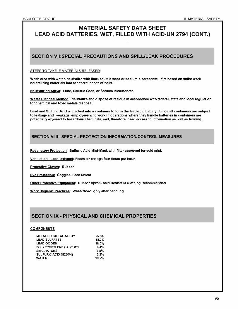
HAULOTTE GROUP 8 MATERIAL SAFETY
95
MATERIAL SAFETY DATA SHEET LEAD ACID BATTERIES, WET, FILLED WITH ACID-UN 2794 (CONT.)
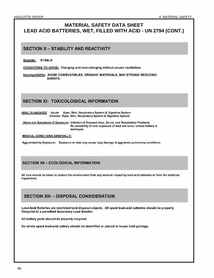
HAULOTTE GROUP 8 MATERIAL SAFETY
96
MATERIAL SAFETY DATA SHEET LEAD ACID BATTERIES, WET, FILLED WITH ACID - UN 2794 (CONT.)
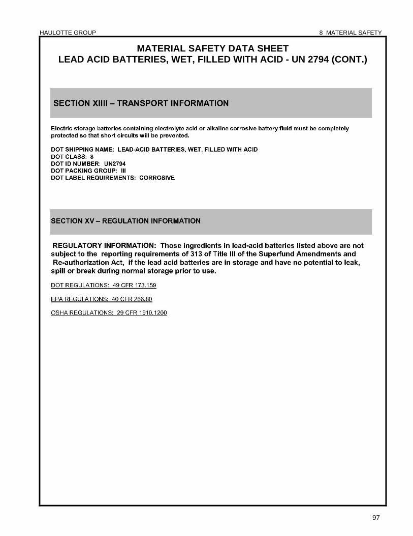
HAULOTTE GROUP 8 MATERIAL SAFETY
97
MATERIAL SAFETY DATA SHEET LEAD ACID BATTERIES, WET, FILLED WITH ACID - UN 2794 (CONT.)
HAULOTTE GROUP 8 MATERIAL SAFETY
98
MATERIAL SAFETY DATA SHEET POWERFLOW™ AW HVI HYDRAULIC OIL

HAULOTTE GROUP 8 MATERIAL SAFETY
99
MATERIAL SAFETY DATA SHEET POWERFLOW™ AW HVI HYDRAULIC OIL (CONTINUED)
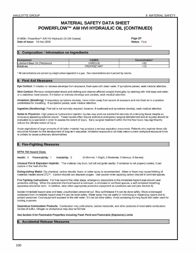
HAULOTTE GROUP 8 MATERIAL SAFETY
100
MATERIAL SAFETY DATA SHEET POWERFLOW™ AW HVI HYDRAULIC OIL (CONTINUED)
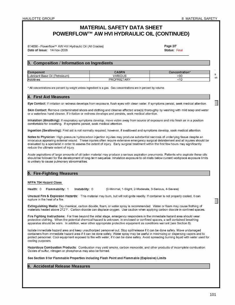
HAULOTTE GROUP 8 MATERIAL SAFETY
101
MATERIAL SAFETY DATA SHEET POWERFLOW™ AW HVI HYDRAULIC OIL (CONTINUED)

HAULOTTE GROUP 8 MATERIAL SAFETY
102
MATERIAL SAFETY DATA SHEET POWERFLOW™ AW HVI HYDRAULIC OIL (CONTINUED)

HAULOTTE GROUP 8 MATERIAL SAFETY
103
MATERIAL SAFETY DATA SHEET POWERFLOW™ AW HVI HYDRAULIC OIL (CONTINUED)

HAULOTTE GROUP 8 MATERIAL SAFETY
104
MATERIAL SAFETY DATA SHEET POWERFLOW™ AW HVI HYDRAULIC OIL (CONTINUED)
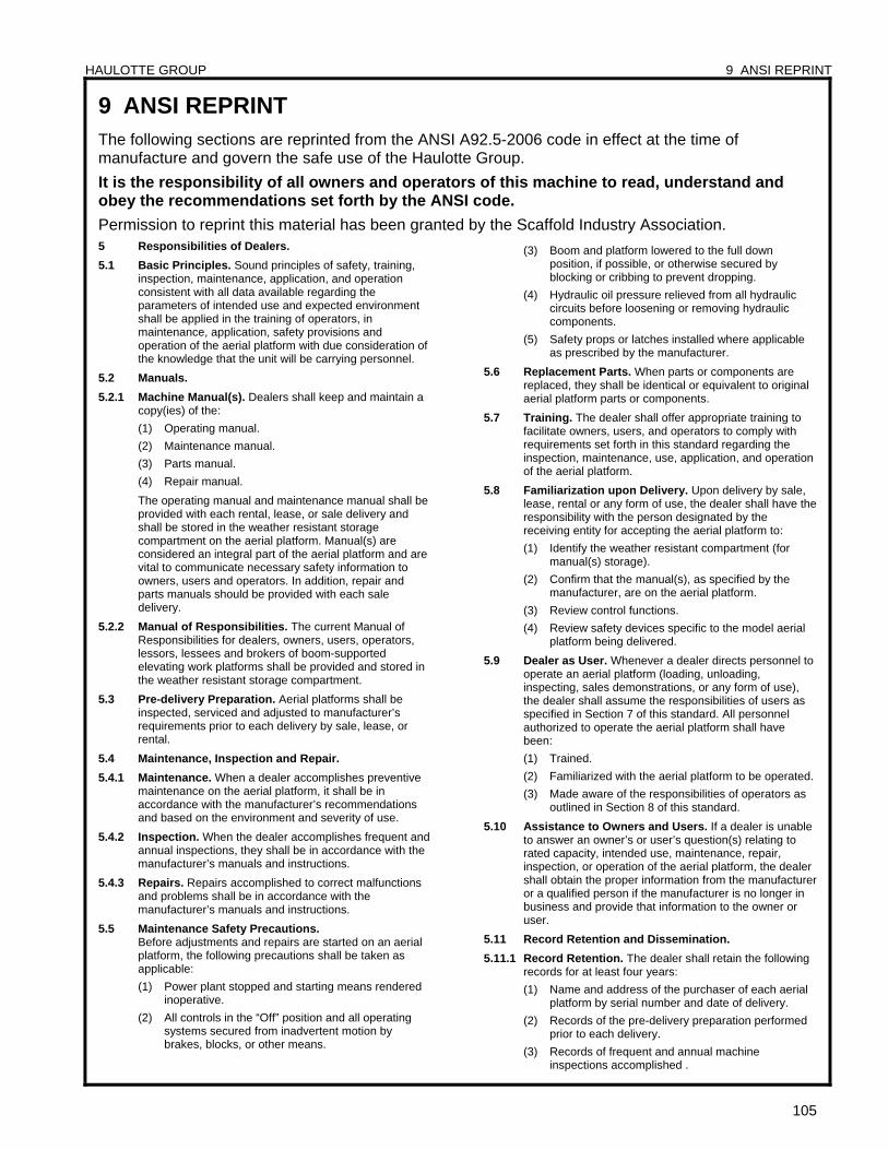
HAULOTTE GROUP 9 ANSI REPRINT
105
9 ANSI REPRINT The following sections are reprinted from the ANSI A92.5-2006 code in effect at the time of manufacture and govern the safe use of the Haulotte Group.
It is the responsibility of all owners and operators of this machine to read, understand and obey the recommendations set forth by the ANSI code.
Permission to reprint this material has been granted by the Scaffold Industry Association. 5 Responsibilities of Dealers.
5.1 Basic Principles. Sound principles of safety, training, inspection, maintenance, application, and operation consistent with all data available regarding the parameters of intended use and expected environment shall be applied in the training of operators, in maintenance, application, safety provisions and operation of the aerial platform with due consideration of the knowledge that the unit will be carrying personnel.
5.2 Manuals.
5.2.1 Machine Manual(s). Dealers shall keep and maintain a copy(ies) of the:
(1) Operating manual.
(2) Maintenance manual.
(3) Parts manual.
(4) Repair manual.
The operating manual and maintenance manual shall be provided with each rental, lease, or sale delivery and shall be stored in the weather resistant storage compartment on the aerial platform. Manual(s) are considered an integral part of the aerial platform and are vital to communicate necessary safety information to owners, users and operators. In addition, repair and parts manuals should be provided with each sale delivery.
5.2.2 Manual of Responsibilities. The current Manual of Responsibilities for dealers, owners, users, operators, lessors, lessees and brokers of boom-supported elevating work platforms shall be provided and stored in the weather resistant storage compartment.
5.3 Pre-delivery Preparation. Aerial platforms shall be inspected, serviced and adjusted to manufacturer’s requirements prior to each delivery by sale, lease, or rental.
5.4 Maintenance, Inspection and Repair.
5.4.1 Maintenance. When a dealer accomplishes preventive maintenance on the aerial platform, it shall be in accordance with the manufacturer’s recommendations and based on the environment and severity of use.
5.4.2 Inspection. When the dealer accomplishes frequent and annual inspections, they shall be in accordance with the manufacturer’s manuals and instructions.
5.4.3 Repairs. Repairs accomplished to correct malfunctions and problems shall be in accordance with the manufacturer’s manuals and instructions.
5.5 Maintenance Safety Precautions. Before adjustments and repairs are started on an aerial
platform, the following precautions shall be taken as applicable:
(1) Power plant stopped and starting means rendered inoperative.
(2) All controls in the “Off” position and all operating systems secured from inadvertent motion by brakes, blocks, or other means.
(3) Boom and platform lowered to the full down position, if possible, or otherwise secured by blocking or cribbing to prevent dropping.
(4) Hydraulic oil pressure relieved from all hydraulic circuits before loosening or removing hydraulic components.
(5) Safety props or latches installed where applicable as prescribed by the manufacturer.
5.6 Replacement Parts. When parts or components are replaced, they shall be identical or equivalent to original aerial platform parts or components.
5.7 Training. The dealer shall offer appropriate training to facilitate owners, users, and operators to comply with requirements set forth in this standard regarding the inspection, maintenance, use, application, and operation of the aerial platform.
5.8 Familiarization upon Delivery. Upon delivery by sale, lease, rental or any form of use, the dealer shall have the responsibility with the person designated by the receiving entity for accepting the aerial platform to:
(1) Identify the weather resistant compartment (for manual(s) storage).
(2) Confirm that the manual(s), as specified by the manufacturer, are on the aerial platform.
(3) Review control functions.
(4) Review safety devices specific to the model aerial platform being delivered.
5.9 Dealer as User. Whenever a dealer directs personnel to operate an aerial platform (loading, unloading, inspecting, sales demonstrations, or any form of use), the dealer shall assume the responsibilities of users as specified in Section 7 of this standard. All personnel authorized to operate the aerial platform shall have been:
(1) Trained.
(2) Familiarized with the aerial platform to be operated.
(3) Made aware of the responsibilities of operators as outlined in Section 8 of this standard.
5.10 Assistance to Owners and Users. If a dealer is unable to answer an owner’s or user’s question(s) relating to rated capacity, intended use, maintenance, repair, inspection, or operation of the aerial platform, the dealer shall obtain the proper information from the manufacturer or a qualified person if the manufacturer is no longer in business and provide that information to the owner or user.
5.11 Record Retention and Dissemination.
5.11.1 Record Retention. The dealer shall retain the following records for at least four years:
(1) Name and address of the purchaser of each aerial platform by serial number and date of delivery.
(2) Records of the pre-delivery preparation performed prior to each delivery.
(3) Records of frequent and annual machine inspections accomplished .
HAULOTTE GROUP 9 ANSI REPRINT
106
(4) Records of repairs accomplished to correct malfunctions and problems.
(5) Name of the person(s) trained.
(6) Name of the person(s) providing the training.
(7) Date of Training.
(8) Name of person(s) receiving familiarization with the aerial platform upon each delivery unless this individual has been provided with familiarization on the same model, or one having characteristics consistent with the one being delivered, within the prior 90 days.
5.11.2 Proof of training. The dealer should provide trainees who successfully complete training a means to evidence they are trained.
The dealer shall provide such proof if requested by the trainee. The document evidencing training shall include the following information:
(1) Name of trainee.
(2) Name of entity providing training or retraining.
(3) Name of trainer(s).
(4) Clear identification that training covered Boom-Supported Elevating Work Platforms.
(5) Date of training.
5.11.3 Record dissemination. Upon request, the dealer shall provide the following information:
(1) To the owner of the aerial platform, a copy of frequent or annual inspections performed.
(2) To the owner of the aerial platform, a copy of repairs accomplished.
(3) To a user, proof of training for an operator, including name of trainer and date of training.
(4) To a user, the name of the person(s) receiving familiarization upon delivery of the aerial platform.
5.12 Modifications. Modification, alteration or remanufacture of an aerial platform shall be made only with prior written permission of the manufacturer.
5.13 Manufacturer’s safety bulletins. The dealer shall comply with safety related bulletins as received from the manufacturer.
5.14 Responsibilities upon sale. When the aerial platform is sold, the dealer:
(1) Shall, upon delivery, ensure the operating and maintenance manuals are conveyed to the owner.
(2) Shall, upon delivery, provide a copy of the current Manual of Responsibilities.
(3) Should, within 60 days of sale, provide repair and parts manuals.
(4) Shall, within 60 days of the sale, notify the manufacturer or its successor (if existing) of the sale, providing the full name and address of the purchaser.
(5) Should, if the aerial platform is used, accomplish an annual machine inspection prior to delivery and provide a copy to the purchaser within 60 days of the sale.
(6) Shall, upon delivery, familiarize the person designated by the receiving entity with the aerial platform being acquired.
6 Responsibilities of Owners.
6.1 Basic Principles. Sound principles of safety, training, inspection, maintenance, application, and operation consistent with all data available regarding the parameters of intended use and expected environment shall be applied in the performance of the responsibilities
of owners with due consideration of the knowledge that the aerial platform will be carrying personnel.
6.2 Responsibilities Upon Purchase. Upon purchase of the aerial platform, the buyer:
(1) Shall ensure the operating and maintenance manuals have been received.
(2) Should acquire repair and parts manuals within sixty days (60) of acquisition.
(3) Shall within sixty days (60) of acquisition of the aerial platform provide the manufacturer with the full name and address of the buyer along with the model and serial number of the aerial platform acquired.
(4) Shall, if the aerial platform is used, ensure the frequent inspection and annual inspections are current.
(5) Shall become familiar with and conform to the responsibilities of owners as set forth in the Manual of Responsibilities for Boom-Supported Elevating Work Platforms.
6.3 Manuals.
6.3.1 Machine Manual(s). Owners shall provide a copy(ies) of the operating and maintenance manual(s) with each rental, lease, or sales delivery by ensuring they are properly stored in the weatherproof compartment that is part of the aerial platform. The manual(s) is considered an integral part of the aerial platform and is vital to communicate necessary safety information to owners, users and operators. In addition, repair and parts manual(s) should be provided with each sale delivery.
6.3.2 Manual of Responsibilities. The current Manual of Responsibilities for dealers, owners, users, operators, lessors, lessees and brokers of boom supported elevating work platforms shall be provided and stored in the weather resistant storage compartment.
6.4 Maintenance, Inspection and Repair.
6.4.1 Maintenance. The owner of an aerial platform shall arrange that the maintenance specified in this standard is properly performed on a timely basis. The owner shall establish a preventive maintenance program in accordance with the manufacturer’s recommendations and in accordance with the environment and severity of use of the aerial platform.
6.4.2 Inspection. The owner shall arrange for frequent and annual inspections to be performed in accordance with the recommendations of the manufacturer. All malfunctions and problems identified in the inspection shall be corrected before the aerial platform is returned to service.
6.4.3 Repairs. When the aerial platform is damaged or in need of repair, all malfunctions and problems identified shall be corrected before the aerial platform is returned to service.
6.5 Pre-delivery Preparation. Aerial platforms shall be inspected, serviced, and adjusted in accordance with the manufacturer’s specifications prior to each delivery by sale, lease, or rental.
6.6 Frequent Inspection. The owner of an aerial platform shall ensure that a frequent inspection is performed in accordance with the manufacturer’s instructions, on an aerial platform:
(1) That was purchased used. This inspection shall be accomplished unless it is determined that the frequent and annual inspections are current.
(2) That has been in service for three months or 150 hours, whichever comes first.
HAULOTTE GROUP 9 ANSI REPRINT
107
(3) That has been out of service for a period longer than 3 months.
The inspection shall be made by a person qualified as a mechanic on the specific type aerial platform or one having similar design characteristics. The inspection shall be in accordance with items specified by the manufacturer for a frequent inspection and shall include, but not limited to the following:
(1) All functions and their controls for speed(s), smoothness, and limits of motion.
(2) Lower controls including the provisions for overriding of upper controls.
(3) All chain and cable mechanisms for adjustment and worn or damaged parts.
(4) All emergency and safety devices.
(5) Lubrication of all moving parts, inspection of filter element(s), hydraulic oil, engine oil, and coolant as specified by the manufacturer.
(6) Visual inspection of structural components and other critical components such as fasteners, pins, shafts, and locking devices.
(7) Placards, warnings and control markings.
(8) Items specified by the manufacturer.
(9) Emergency lowering means.
6.7 Annual Inspection. The owner of an aerial platform shall ensure that an annual inspection is performed on the aerial platform no later than thirteen (13) months from the date of the prior annual inspection. The inspection shall be made by a person(s) qualified as a mechanic on the specific type of aerial platform or one having similar design characteristics. The inspection shall be in accordance with items specified by the manufacturer for an annual inspection. The owner shall not place the aerial platform into service until all malfunctions and problems have been corrected.
6.8 Maintenance safety precautions. Before adjustments and repairs are started on an aerial platform, the following precautions shall be taken as applicable:
(1) Power plant stopped and starting means rendered inoperative.
(2) All controls in the “Off” position and all operating systems secured from inadvertent motion by brakes, blocks, or other means.
(3) Elevating assembly and platform lowered to the full down position, if possible, or otherwise secured by blocking or cribbing to prevent dropping.
(4) Hydraulic oil pressure relieved from all hydraulic circuits before loosening or removing hydraulic components.
(5) Safety props or latches installed where applicable as prescribed by the manufacturer.
(6) Precautions specified by the manufacturer.
6.9 Replacement parts. When parts or components are replaced, they shall be identical or equivalent to original aerial platform parts or components.
6.10 Maintenance training. The owners shall train their maintenance personnel in inspection and maintenance of the aerial platform in accordance with the manufacturer’s recommendations and Sections 6.2, 6.3, 6.4, 6.5, 6.6, 6.7, 6.8, 6.9 and 6.11 of this standard and with the manufacturer’s recommendations.
6.11 Training.
6.11.1 Operator training. Whenever an owner directs or authorizes an employee to operate an aerial platform, (loading, unloading, inspecting or any form of use) the
owner shall assume the responsibilities of the user as specified in Section 7 of this standard and shall ensure the person has been:
(1) Trained.
(2) Familiarized with the aerial platform to be operated.
(3) Made aware of the responsibilities of operators as outlined in Section 8 of this standard.
6.11.2 Assistance to user. Upon request of the user, when an owner sells, leases, rents or provides an aerial platform for any form of beneficial use, the owner at that time shall offer to do training or advise the user where training may reasonably be secured.
6.12 Familiarization upon delivery. Upon delivery for lease, rental or any form of beneficial use, the owner shall have the responsibility with the person designated by the receiving entity for accepting the aerial platform to:
(1) Identify the weather resistant compartment (for manual(s) storage).
(2) Confirm all manuals, as specified by the manufacturer, are on the aerial platform.
(3) Review control functions with the operator or person(s) designated by the user.
(4) Review safety devices specific to the model aerial platform being delivered.
6.13 Operation. When an owner operates an aerial platform, the owner shall have the responsibilities of users as specified in Section 7 of this standard and his operating personnel shall have responsibilities of operators as specified in Section 8 of this standard.
6.14 Assistance to users and operators. If an owner is unable to answer a user’s or operator’s question(s) relating to rated capacity, intended use, maintenance, repair, inspection, or operation of the aerial platform, the owner shall obtain the proper information from the dealer or manufacturer and provide that information to the user or operator.
6.15 Record Retention and Dissemination.
6.15.1 Record Retention. The owner shall date and retain the following records for at least 4 years:
(1) Name and address of the purchaser of each aerial platform by serial number and date of delivery.
(2) Written records of the frequent and annual inspections performed. The record shall include deficiencies found, corrective action accomplished and identification of the person(s) performing the inspection and repairs.
(3) Written records of repairs accomplished on the aerial platform. The records shall include corrective action accomplished and identification of the person(s) performing the repairs.
(4) Pre-delivery preparation performed prior to each delivery.
(5) Name of the person(s) trained.
(6) Name of person(s) providing training.
(7) Name of person(s) receiving familiarization upon each delivery unless the individual has been provided with familiarization on the same model, or one having characteristics consistent with the one being delivered, within the prior 90 days.
(8) Name of person(s) providing familiarization upon delivery.
6.15.2 Proof of Training. Owners providing training should provide successful trainees a means to evidence their training and shall provide such proof if requested by the
HAULOTTE GROUP 9 ANSI REPRINT
108
trainee. The document evidencing training shall include the following information:
(1) Name of entity providing training or retraining.
(2) Name of trainer(s).
(3) Clear identification that training covered Boom-Supported Elevating Work Platforms.
(4) Date of training.
(5) Name of trainee.
6.15.3 Record dissemination. Upon request, an owner accomplishing training and/or familiarization shall provide the following:
(1) To a user, proof of training for an operator, including name of trainer and date of training.
(2) To a user, the name of the person(s) receiving familiarization upon delivery of the aerial platform.
6.16 Modifications. The owner shall not modify or concur in modification or alteration to the aerial platform without the modifications being approved and certified in writing by the manufacturer.
6.17 Manufacturer’s Safety Bulletins. The owner shall comply with safety related bulletins as received from the manufacturer or dealer.
6.18 Responsibilities upon Sale. Upon sale of the aerial platform, the seller:
(1) Shall, upon delivery, ensure the operating and maintenance manuals are conveyed to the new owner.
(2) Shall, upon delivery, provide a copy of the current Manual of Responsibilities to the new owner.
(3) Should provide repair and parts manuals to the new owner.
(4) Shall, upon the request of the new owner, offer training or advise where training may reasonably be obtained.
7 Responsibilities of Users.
7.1 Basic principles. The information in this standard must be supplemented by good job management, safety control, and the application of sound principles of safety, training, inspection, maintenance, application and operation, consistent with all data available regarding the parameters of intended use and expected environment. Since the user has direct control over the application and operation of aerial platforms, conformance with good safety practices in this area is the responsibility of the user and the operating personnel, including the operator. Decisions on the use and operation of the aerial platform must always be made with due consideration for the fact that the aerial platform will be carrying personnel whose safety is dependent on those decisions.
7.2 Manuals.
7.2.1 Machine manuals. Users shall keep and maintain a copy (ies) of the operating and maintenance manual(s) in the weather resistant storage compartment provided by the manufacturer. The manual(s) is considered an integral part of the aerial platform and is vital to communicate necessary safety information to users and operators.
7.2.2 Manual of Responsibilities. The current Manual of Responsibilities for dealers, owners, users, operators, lessors, lessees and brokers of boom supported elevating work platforms shall be provided and stored in the weather resistant storage compartment.
7.3 Inspection and Maintenance. Users shall inspect and maintain the aerial platform as required to ensure proper operation. The frequency of inspection and maintenance
shall be determined by the manufacturer’s recommendations and be compatible with operating conditions and the severity of the operating environment. Aerial platforms that are not in proper operating condition shall be immediately removed from service until repaired. Repairs shall be made by a qualified person and the repairs shall be in conformance with the manufacturer’s recommendations.
7.3.1 Frequent Inspection. Users of an aerial platform shall ensure that frequent inspections are conducted as outlined in Section 6.6 of this standard.
7.3.2 Annual Inspection. Users of an aerial platform shall ensure that annual inspections are conducted as outlined in Section 6.7 of this standard.
7.3.3 Pre-start inspection. Before use each day or at the beginning of each shift, the aerial platform shall be given a visual inspection and functional test including, but not limited to, the following:
(1) Operating and emergency controls.
(2) Safety devices.
(3) Air, hydraulic and fuel system leaks.
(4) Cables and wiring harness.
(5) Loose or missing parts.
(6) Tires and wheels.
(7) Placards, warnings, control markings, and operating manual(s).
(8) Outriggers, stabilizers, extendable axles and other structures.
(9) Guardrail system.
(10) Items specified by the manufacturer.
7.3.4 Maintenance Safety Precautions. Before adjustments and repairs are started on an aerial platform, the following precautions shall be taken as applicable:
(1) Power plant stopped and starting means rendered inoperative.
(2) All controls in the “Off” position and all operating systems secured from inadvertent motion by brakes, blocks, or other means.
(3) Boom and platform lowered to the full down position, if possible, or otherwise secured by blocking or cribbing to prevent dropping.
(4) Hydraulic oil pressure relieved from all hydraulic circuits before loosening or removing hydraulic components.
(5) Safety props or latches installed where applicable as prescribed by the manufacturer.
(6) Precautions specified by the manufacturer.
7.4 Replacement Parts. When parts or components are replaced, they shall be identical or equivalent to original aerial platform parts or components.
7.5 Maintenance Training. The user shall ensure only qualified personnel inspect and maintain the aerial platform in accordance with the manufacturer’s recommendations and Section 7.3, 7.4 and 7.6 of this standard and with the manufacturer’s recommendations.
7.6 Operator Training and Retraining. Whenever a user directs or authorizes an individual to operate an aerial platform, the user shall ensure that the person has been:
(1) Trained before being assigned to operate the aerial platform.
(2) Familiarized with the aerial platform to be operated.
(3) Made aware of responsibilities of operators as outlined in Section 8 of this standard.
HAULOTTE GROUP 9 ANSI REPRINT
109
(4) Retrained, if necessary, based on the user’s observation and evaluation of the operator.
7.6.1 Trainee Records. A record of the trainee’s aerial platform instruction shall be maintained by the user for at least four (4) years.
7.7 Familiarization Before Use. The user shall permit only properly trained personnel to operate an aerial platform. The user shall ensure that before use the operator is familiar with the model of the aerial platform to be operated, and specifically:
(1) Knows where the weather resistant compartment for manual(s) storage is located.
(2) Knows the operating and maintenance manuals supplied by the manufacturer are stored in the weather resistant compartment and is familiar with the operating and safety manuals.
(3) Understands all control functions, placards and warnings.
(4) Is aware of and understands all safety devices specific to the model aerial platform being used.
7.8 Work Place Inspection. Before the aerial platform is used and during use, the user shall check the area in which the aerial platform is to be used for possible hazards such as, but not limited to:
(1) Drop-offs or holes, including those concealed by water, ice, mud, etc.
(2) Slope(s).
(3) Bumps and floor obstructions.
(4) Debris.
(5) Overhead obstructions and electrical conductors.
(6) Hazardous locations and atmospheres (reference ANSI/NFPA 505-1996).
(7) Inadequate surface and support to withstand all load forces imposed by the aerial platform in all operating configurations.
(8) Wind and weather conditions.
(9) Presence of unauthorized persons.
(10) Other possible unsafe conditions.
7.9 Determination of Hazardous Locations. It shall be the responsibility of the user to determine the hazard classification of the intended location of operation. Aerial platforms operated in hazardous locations shall be approved in accordance with, and of the type required, by ANSI/NFPA 505-1996.
7.10 Operator Warnings and Instructions. The user shall direct personnel operating the aerial platform to be in compliance with the provisions set forth in this standard. The user shall monitor their performance and supervise their work to ensure the use, application, and operation of the aerial platform is in conformance with the provisions set forth in Section 8 of this standard, warn personnel of potential hazards, provide means to protect against identified hazards, and explain the potential consequences of not following proper operating guidelines. Instructions and guidelines regarding proper operation shall include, but not necessarily be limited to the following issues and subjects:
(1) Fall Protection. Principal fall protection is provided by the guardrail system. The user shall direct and monitor the operator to ensure that all components of the guardrail system are in place. The user shall direct and monitor occupants of the work platform to ensure that they wear a personal fall arrest system to protect against the potential effects of ejection or a fall restraint system to prevent free fall.
(a) Election of Systems: The user may elect to use either a restraint or an arrest system.
1. Fall Restraint Systems – An anchorage, belt or harness and a lanyard which prevent free fall. These systems are arranged to keep occupants in the platform in the event of dynamic forces which might cause ejection.
(1.1) Occupants shall use a restraint system to keep the occupant(s) within the platform.
(1.2) Restraint systems may include either belts or harnesses and do not include arresting or deceleration devices.
2. Fall Arrest System – An anchorage, full body harness and a lanyard used to arrest an employee in a fall from an aerial platform. Such systems allow a fall over the guardrail system. The force applied to the body shall be limited to 1800 lbs. (8,000N).
(2.1) A fall arrest system shall allow workers to move around the platform but provide a minimum of lanyard slack.
(2.2) A fall arrest system for aerial lifts shall include a lanyard, and full body harness. A deceleration device if used will not allow a fall further than that required to arrest the fall without exceeding 1800 lbs. (8,000N) of force on the worker. Fall arrest systems, beyond the anchorage, are not part of the aerial work platform and are to be specified and supplied by the user of the aerial work platform.
(2) Slope and grade. The aerial platform shall not be operated in any manner on grades, side slopes or ramps exceeding those for which the aerial platform is rated by the manufacturer.
(3) Deployment of stability enhancing means. Outriggers, stabilizers, extendable axles, oscillating axles or other stability enhancing means shall be deployed and locked into place as required by the manufacturer.
(4) Guardrail system. Guardrails shall be installed and positioned, and access gates or openings shall be properly closed per the manufacturer’s instructions.
(5) Distribution of load. The load and its distribution on the platform and any platform extension(s) shall be in accordance with the manufacturer’s rated capacity for that specific configuration.
(6) Maintaining overhead clearance. The operator shall be instructed to ensure that adequate clearance is maintained from overhead obstructions and energized electrical conductors and parts.
(7) Electrocution hazard. All applicable safety related work practices intended to prevent electric shock covered by the Code of Federal Regulations (CFR) 1910.333 shall be defined and explained to the operator by a qualified person. In particular, such person shall direct the operator commensurate with the operators qualifications to maintain the minimum approach distance (MAD) from energized power lines and covered by CFR1910.333c.
(8) Personal protective equipment (PPE). The user shall direct the operator to ensure all
personnel on the platform wear personal protective equipment (PPE) as required.
(9) Personnel footing. Personnel shall maintain a firm footing on the platform floor while working thereon. Climbing by occupants on the mid-rail or top-rail of the aerial platform is prohibited. The use of planks,
HAULOTTE GROUP 9 ANSI REPRINT
110
ladders, or any other devices on the platform for achieving additional height or reach is prohibited.
(10) Precaution for other moving equipment. When other moving equipment and vehicles are present, special precautions shall be taken to comply with local ordinances or safety standards established for the workplace.
Warnings such as, but not limited to, flags, roped off areas, flashing lights, and barricades shall be used as appropriate.
(11) Reporting problems or malfunctions. The user shall direct the operator to immediately
report to a supervisor any problem(s) or malfunction(s) that become evident during operation. The user shall ensure all problems and malfunctions that affect the safety of operations are repaired prior to continued use.
(12) Reporting potentially hazardous locations. The user shall direct the operator to immediately report to a supervisor any potentially hazardous location(s) that become evident during operation.
(13) Hazardous location operation. Operation of aerial platforms not approved and
marked for operation in a hazardous location shall be prohibited.
(14) Entanglement. Care shall be taken to prevent rope, electric cords, and hoses, etc., from becoming entangled in the aerial platform.
(15) Capacity limitations. Rated capacities and rated number of occupants shall not be exceeded when loads are transferred to the platform at any height.
(16) Work area. The user shall direct the operator to ensure the area surrounding the aerial platform is clear of personnel and equipment before lowering the platform.
(17) Fueling. The engine (if applicable) shall be shut down while fuel tanks are being filled.
Fueling shall be done in a well ventilated area free of flame, sparks, or other hazards that may cause fire or explosion.
(18) Battery charging. Batteries shall be charged in a well ventilated area free of flame, sparks, or other hazards that may cause fire or explosion.
(19) Improper platform stabilization. The aerial platform shall not be positioned against another object to steady the platform or improve stability.
(20) Misuse as a crane. The aerial platform shall not be used as a crane.
(21) Unusual operating support conditions. The aerial platform shall not be operated from a
position on trucks, trailers, railway cars, floating vessels, scaffolds, or similar equipment unless the application is approved in writing by the manufacturer or a qualified person.
(22) Travel speeds. The user shall direct the operator to limit travel speed according to conditions, including the condition of the support surface, congestion, visibility, slope, location of personnel, and other factors leading to hazards which may cause collision(s) or result in potential injury(ies) to personnel.
(23) Driving requirements. Before and during driving while the platform is elevated, the user shall direct the operator to:
(a) Maintain a clear view of the support surface and route of travel.
(b) Ensure personnel in the worksite area that may be affected are aware of the movement, communicating and maneuvering the aerial platform as required to protect against personal injury.
(c) Maintain a safe distance from obstacles, debris, drop-offs, holes, depressions, ramps, and other hazards to ensure safe travel.
(d) Maintain a safe distance from overhead obstructions and energized electrical conductors.
(24) Stunt driving. Stunt driving and horseplay are prohibited.
(25) Securing the aerial platform. The user shall direct the operator to implement means provided to protect against use by an unauthorized person(s).
(26) Altering safety devices. Interlocks or other safety devices shall not be altered or disabled.
(27) Snagged platform. If the platform or elevating assembly becomes caught, snagged, or otherwise prevented from normal motion by adjacent structures or other obstacles such that control reversal does not free the platform, all personnel shall be removed from the platform before attempts are made to free the platform using lower controls.
(28) Vacating (or entering) an elevated aerial platform. If permitted by the manufacturer, personnel shall only vacate or enter a raised aerial platform by following the guidelines and instructions provided by the manufacturer.
(29) Modifications. Modification or alteration of an aerial platform or the fabrication and attaching of frameworks, or the mounting of attachments for holding tools or materials onto the platform or the guardrail system shall only be accomplished with the prior written permission of the manufacturer.
(30) Assistance to the operator. If an operator encounters any suspected malfunction of the aerial platform, or any hazard or potentially unsafe condition relating to capacity, intended use or safe operation of the aerial platform, the operator shall cease operation of the aerial platform and request further information from the user.
(31) Problems or malfunctions. Any problem(s) or malfunction(s) that affect the safety of operations shall be repaired prior to the use of the aerial platform.
(32) Carrying materials (larger than the platform). The user shall ensure that only properly secured tools and materials which are evenly distributed and can be safely handled by a person(s) working from the platform, are moved.
(33) Rated horizontal force. The user shall direct the operator not to exceed the manufacturer’s rated horizontal force.
(34) Bridge cranes. When an aerial platform is to operate within the area of travel of a bridge crane or similar equipment, steps shall be taken to prevent a collision with the aerial platform.
(35) Adequate support requirements. The user shall ensure the support surface is adequate for the aerial platform and the load carried.
(36) Leveling the aerial platform. Outriggers and leveling devices supplied by the manufacturer shall be utilized to level the aerial platform when provided.
HAULOTTE GROUP 9 ANSI REPRINT
111
(37) Protecting against unauthorized use. The user shall direct the operator not to use, rent, lease, or provide the aerial platform for any form of beneficial use unless so authorized.
7.11 User as Operator. If a user is also the operator of an aerial platform, the user shall have the responsibilities of operators specified in Section 8 of this standard as well as responsibilities of users as specified in Section 7 of this standard.
7.12 Shutdown of Aerial Platform. The user shall authorize and direct the operating personnel to cease operation of the aerial platform in case of any suspected malfunction(s) of the aerial platform, or any hazard or potentially unsafe condition(s) that may be encountered and to request further information as to safe operation from the owner, dealer, or manufacturer before further operation of the aerial platform.
7.13 Record Retention and Dissemination.
7.13.1 Record Retention. The user shall retain the following records for at least 4 years:
(1) Names of the operator(s) trained and retrained.
(2) Names of operator(s) provided familiarization.
(3) The owner (or the entity designated by the owner) is responsible to ensure frequent and annual inspections are conducted and written records are maintained. The records shall include the date of the inspection, any deficiencies found, the corrective action recommended and identification of the person(s) performing the inspection.
(4) When employees of the user accomplish repairs on the aerial platform, the user shall maintain written records. The record shall include the date of repair, a description of the work accomplished and identification of the person(s) performing the repair.
7.13.2 Record Dissemination
(1) When the user directs personnel to accomplish frequent or annual inspections, not later than 60 days after the inspections, the appropriate records shall be provided to the owner of the aerial platform.
(2) When the user directs personnel to accomplish repairs on the aerial platform, not later than 60 days after the repairs are accomplished, the appropriate records shall be provided to the owner.
7.13.3 Proof of Training. Users providing training should provide successful trainees a means to evidence their training and shall provide such proof if requested by the trainee.
The document evidencing training shall include the following information:
(1) Name of entity providing training or retraining.
(2) Name of trainer(s).
(3) Clear identification that training covered Boom-Supported Elevating Work Platforms.
(4) Date of training.
(5) Name of trainee.
7.14 Modifications. Modification, alteration or remanufacture of an aerial platform shall be made only with prior written permission of the manufacturer.
7.15 Manufacturer’s Safety Bulletins. The user shall comply with safety related bulletins as received from the manufacturer, dealer, or owner.
8 Responsibilities of Operators.
8.1 Basic Principles. The information in this standard shall be supplemented by good judgment, safety control, and
caution in evaluating each situation. Since the operator is in direct control of the aerial platform, conformance with good safety practices in this area is the responsibility of the operator. The operator shall make decisions on the use and operation of the aerial platform with due consideration for the fact that his or her own safety as well as the safety of others is dependent on those decisions.
8.2 Manuals.
8.2.1 Machine Manuals. The operator shall ensure the operating and maintenance manuals are stored in the weather resistant storage compartment on the aerial platform. The manual(s) is considered an integral part of the aerial platform and is vital to communicate necessary safety information to the operator. The operator shall be familiar with the manuals and reference them as required.
8.2.2 Manual of Responsibilities. The operator shall be familiar with the requirements for operators as set forth in Section 8 of the Manual of Responsibilities for Dealers, Owners, Users, Operators, Lessors, Lessees and Brokers of Boom-Supported Elevating Work Platforms. The current Manual of Responsibilities shall be kept with the aerial platform at all times and stored in the weather-resistant compartment when not in use.
8.3 Prestart Inspection. Before use each day or at the beginning of each shift, the aerial platform shall be given a visual inspection and functional test including, but not limited to, the following:
(1) Operating and emergency controls
(2) Safety devices
(3) Personal protective devices
(4) Air, hydraulic and fuel system(s) leaks
(5) Cables and wiring harness
(6) Loose or missing parts
(7) Tires and wheels
(8) Placards, warnings, control markings and operating manual(s)
(9) Outriggers, stabilizers, extendable axles and other structures
(10) Guardrail system
(11) Items specified by the manufacturer
8.4 Problems or malfunctions. Any problems or malfunctions that affect the safety of operations shall be repaired prior to the use of the aerial platform.
8.5 Training, Retraining, and Familiarization
8.5.1 General Training. Only personnel who have received general instructions regarding the inspection, application and operation of aerial platforms, including recognition and avoidance of hazards associated with their operation, shall operate an aerial platform. Such items covered shall include, but not necessarily be limited to, the following issues and requirements:
(1) The purpose and use of manuals.
(2) That operating manuals are an integral part of the aerial platform and must be stored properly in the weather resistant compartment when not in use.
(3) A pre-start inspection.
(4) Responsibilities associated with problems or malfunctions affecting the operation of the aerial platform.
(5) Factors affecting stability.
(6) The purpose of placards and decals.
(7) Workplace inspection.
HAULOTTE GROUP 9 ANSI REPRINT
112
(8) Safety rules and regulations.
(9) Authorization to operate.
(10) Operator warnings and instructions.
(11) Actual operation of the aerial platform.
Under the direction of a qualified person, the trainee shall operate the aerial platform for a sufficient period of time to demonstrate proficiency in the actual operation of the aerial platform.
8.5.2 Retraining. The operator shall be retrained, when so directed by the user, based on the user’s observation and evaluation of the operator.
8.5.3 Familiarization. When an operator is directed to operate an aerial platform he/she is not familiar with, the operator shall receive instructions regarding the following items:
(1) The location of the weather resistant compartment (for manual(s) storage).
(2) The purpose and function of all controls.
(3) Safety devices and operating characteristics specific to the aerial platform.
8.6 Before Operation. Before operation, the operator shall:
(1) Read and understand the manufacturer’s operating instruction(s) and user’s safety rules, or have them explained
(2) Understand all labels, warnings, and instructions displayed on the aerial platform or have them explained.
(3) Ensure all occupants of the aerial platform wear appropriate personal protective equipment (PPE) for the conditions, including the environment in which the aerial platform will be operated.
8.7 Workplace Inspection. Before the aerial platform is used and during use, the operator shall check the area in which the aerial platform is to be used for possible hazards such as, but not limited to:
(1) Drop-offs or holes, including those concealed by water, ice, mud, etc.
(2) Slope(s).
(3) Bumps and floor obstructions.
(4) Debris.
(5) Overhead obstructions and electrical conductors.
(6) Hazardous locations and atmospheres (reference ANSI/NFPA 505-1987).
(7) Inadequate surface and support to withstand all load forces imposed by the aerial platform in all operating configurations.
(8) Wind and weather conditions.
(9) Presence of unauthorized persons.
(10) Other possible unsafe conditions.
8.8 Prior to each operation. Before each operation of the platform, the operator shall ensure:
(1) Outriggers, stabilizers, extendable axles, or other stability enhancing means, are used as required by the manufacturer.
(2) Guardrails are installed and access gates or openings are closed per manufacturer’s instructions.
(3) The load and its distribution on the platform and any platform extension(s) are in accordance with the manufacturer’s rated capacity for that specific configuration.
(4) All personnel on the aerial platform have appropriate safety gear for the work and environment envisioned.
8.9 Understanding of Hazardous Locations. It shall be the responsibility of the operator to understand the hazard classification of the intended location of operation according to ANSI/NFPA 505-1996.
8.10 Operator warnings and instructions. The operator shall direct personnel operating the aerial platform to be in compliance with the provisions set forth in this standard. The operator shall monitor their performance and supervise their work to ensure the use, application, and operation of the aerial platform is in conformance with the provisions set forth in Section 8 of this standard, warn personnel of potential hazards, provide means to protect against identified hazards, and explain the potential consequences of not following proper operating guidelines. Instructions and guidelines regarding proper operation shall include, but not necessarily be limited to the following issues and subjects:
(1) Fall protection. While the guardrail system of the aerial platform provides primary fall protection all occupants of the work platform shall wear either fall restraint or fall arrest equipment as directed by their employer.
(2) Slope and grade. The aerial platform shall not be operated in any manner on grades, side slopes, or ramps exceeding those for which the aerial platform is rated by the manufacturer.
(3) Deployment of stability enhancing means. Outriggers, stabilizers, extendable axles or other stability enhancing means shall be deployed and locked into place as required by the manufacturer.
(4) Guardrail system. Guardrails shall be installed and positioned, and access gates or openings shall be properly closed per the manufacturer’s instructions.
(5) Distribution of load. The load and its distribution on the platform and any platform extension(s) shall be in accordance with the manufacturer’s rated capacity for that specific configuration.
(6) Maintaining overhead clearance. The operator shall be instructed to ensure that adequate clearance is maintained from overhead obstructions and energized electrical conductors and parts.
(7) Electrocution hazard. The operator shall perform only the work for which he or she is qualified, in compliance with all applicable safety related work practices intended to prevent electric shock covered by the Code of Federal Regulations (CFR) 1910.333. The operator’s level of competence shall be established only by persons qualified to do so. Operators shall maintain the appropriate minimum approach distance (MAD) from energized power lines and parts covered by CFR 1910.333 (c).
(8) Personal Protective Equipment. The operator shall ensure all personnel on the platform wear personal protective equipment as required.
(9) Personnel footing. Personnel shall maintain a firm footing on the platform floor while working thereon. Climbing by occupants on the mid-rail or top-rail of the aerial platform is prohibited. The use of planks, ladders, or any other devices on the platform for achieving additional height or reach is prohibited.
(10) Precaution for other moving equipment. When other moving equipment and vehicles are present, special precautions shall be taken to comply with local ordinances or safety standards established for the workplace.
Warnings such as, but not limited to, flags, roped off areas, flashing lights, and barricades shall be used as appropriate.
HAULOTTE GROUP 9 ANSI REPRINT
113
(11) Reporting problems or malfunctions. The operator shall immediately report to a supervisor any problem(s) or malfunction(s) that become evident during operation. The operator shall ensure all problems and malfunctions that affect the safety of operations are repaired prior to continued use.
(12) Reporting potentially hazardous locations. The operator shall immediately report to a supervisor any potentially hazardous location(s) that become evident during operation.
(13) Hazardous location operation. Operation of aerial platforms not approved and marked for operation in a hazardous location shall be prohibited.
(14) Entanglement. Care shall be taken to prevent rope, electric cords, and hoses, etc., from becoming entangled in the aerial platform.
(15) Capacity limitations. Rated capacities shall not be exceeded when loads are transferred to the platform at any height.
(16) Work area. The operator shall ensure the area surrounding the aerial platform is clear of personnel and equipment before lowering the platform.
(17) Fueling. The engine (if applicable) shall be shut down while fuel tanks are being filled.
Fueling shall be done in a well-ventilated area free of flame, sparks, or other hazards that may cause fire or explosion.
(18) Battery charging. Batteries shall be charged in a well ventilated area free of flame, sparks or other hazards that may cause fire or explosion.
(19) Improper platform stabilization. The aerial platform shall not be positioned against another object to steady the platform or improve stability.
(20) Misuse as a crane. The aerial platform shall not be used as a crane.
(21) Unusual operating support conditions. The aerial platform shall not be operated from a position on trucks, trailers, railway cars, floating vessels, scaffolds, or similar equipment unless the application is approved in writing by the manufacturer or a qualified person.
(22) Travel speeds. The operator shall limit travel speed according to conditions, including the condition of the support surface, congestion, visibility, slope, location of personnel, and other factors leading to hazards which may cause collision(s) or result in potential injury(ies) to personnel.
(23) Driving requirements. Before and during driving while the platform is elevated, the operator shall:
(a) Maintain a clear view of the support surface and route of travel
(b) Ensure personnel in the worksite area that may be affected are aware of the movement, communicating and maneuvering the aerial platform as required to protect against personal injury
(c) Maintain a safe distance from obstacles, debris, drop-offs, holes, depressions, ramps, and other hazards to ensure safe travel
(d) Maintain a safe distance from overhead obstacles.
(24) Stunt driving. Stunt driving and horseplay are prohibited.
(25) Securing the aerial platform. The operator shall implement means provided to protect against use by an unauthorized person(s).
(26) Altering safety devices. Interlocks or other safety devices shall not be altered or disabled.
(27) Snagged platform. If the platform or elevating assembly becomes caught, snagged, or otherwise prevented from normal motion by adjacent structures or other obstacles such that control reversal does not free the platform, all personnel shall be removed from the platform before attempts are made to free the platform using lower controls.
(28) Vacating (or entering) an elevated aerial platform. If permitted by the manufacturer, personnel shall only vacate or enter a raised aerial platform by following the guidelines and instructions provided by the manufacturer.
(29) Modifications. Modification or alteration of an aerial platform or the fabrication and attaching of frameworks, or the mounting of attachments for holding tools or materials onto the platform or the guardrail system shall only be accomplished with the prior written permission of the manufacturer.
(30) Assistance to the operator. If an operator encounters any suspected malfunction of the aerial platform, or any hazard or potentially unsafe condition relating to capacity, intended use or safe operation of the aerial platform, the operator shall cease operation of the aerial platform and request further information from the operator.
(31) Problem(s) or malfunction(s). Any problems or malfunctions that affect the safety of operations shall be repaired prior to the use of the aerial platform.
(32) Carrying materials (larger than the platform.) The operator shall ensure that only properly secured tools and materials which are evenly distributed and can be safely handled by a person(s) working from the platform, shall be moved.
(33) Rated horizontal force. The operator shall not exceed the manufacturer’s rated horizontal force.
(34) Bridge cranes or contact with any electrical conductors. When an aerial platform is to operate within the area of travel of a bridge crane or similar equipment, steps shall be taken to prevent a collision with the aerial platform.
(35) Adequate support requirements. The operator shall insure the support surface is adequate for the aerial platform and the load carried.
(36) Leveling the aerial platform. Outriggers and leveling devices supplied by the manufacturer shall be utilized to level the aerial platform when provided.
(37) Protecting against unauthorized use. The operator shall not use, rent, lease, or provide the aerial platform for any form of beneficial use unless so authorized.
8.11 Record of training. When provided or when obtained upon the operator’s request, proof of training by the training entity should be retained by the operator. Records shall contain the following information:
(1) Name of entity providing training or retraining
(2) Name of trainer(s)
(3) Clear identification that training covered Boom-Supported Elevating Work Platforms
(4) Date of training
(5) Name of trainee
9 Responsibilities of Lessors
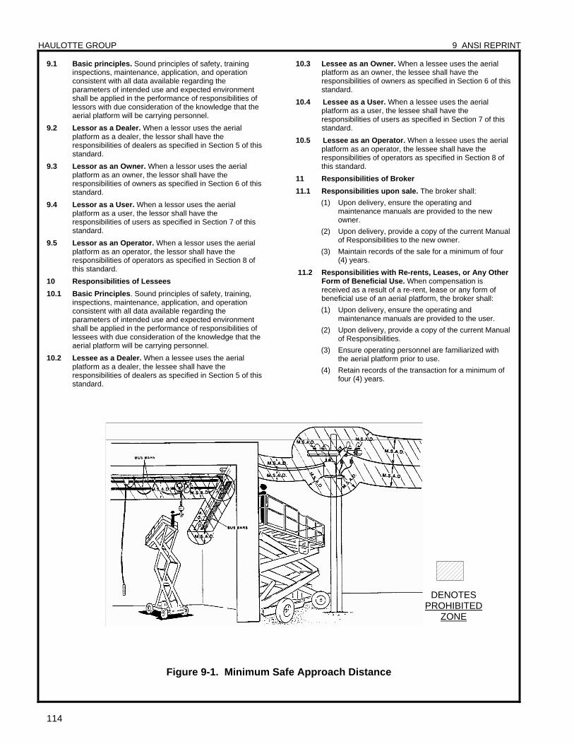
HAULOTTE GROUP 9 ANSI REPRINT
114
9.1 Basic principles. Sound principles of safety, training inspections, maintenance, application, and operation consistent with all data available regarding the parameters of intended use and expected environment shall be applied in the performance of responsibilities of lessors with due consideration of the knowledge that the aerial platform will be carrying personnel.
9.2 Lessor as a Dealer. When a lessor uses the aerial platform as a dealer, the lessor shall have the responsibilities of dealers as specified in Section 5 of this standard.
9.3 Lessor as an Owner. When a lessor uses the aerial platform as an owner, the lessor shall have the responsibilities of owners as specified in Section 6 of this standard.
9.4 Lessor as a User. When a lessor uses the aerial platform as a user, the lessor shall have the responsibilities of users as specified in Section 7 of this standard.
9.5 Lessor as an Operator. When a lessor uses the aerial platform as an operator, the lessor shall have the responsibilities of operators as specified in Section 8 of this standard.
10 Responsibilities of Lessees
10.1 Basic Principles. Sound principles of safety, training, inspections, maintenance, application, and operation consistent with all data available regarding the parameters of intended use and expected environment shall be applied in the performance of responsibilities of lessees with due consideration of the knowledge that the aerial platform will be carrying personnel.
10.2 Lessee as a Dealer. When a lessee uses the aerial platform as a dealer, the lessee shall have the responsibilities of dealers as specified in Section 5 of this standard.
10.3 Lessee as an Owner. When a lessee uses the aerial platform as an owner, the lessee shall have the responsibilities of owners as specified in Section 6 of this standard.
10.4 Lessee as a User. When a lessee uses the aerial platform as a user, the lessee shall have the responsibilities of users as specified in Section 7 of this standard.
10.5 Lessee as an Operator. When a lessee uses the aerial platform as an operator, the lessee shall have the responsibilities of operators as specified in Section 8 of this standard.
11 Responsibilities of Broker
11.1 Responsibilities upon sale. The broker shall:
(1) Upon delivery, ensure the operating and maintenance manuals are provided to the new owner.
(2) Upon delivery, provide a copy of the current Manual of Responsibilities to the new owner.
(3) Maintain records of the sale for a minimum of four (4) years.
11.2 Responsibilities with Re-rents, Leases, or Any Other Form of Beneficial Use. When compensation is received as a result of a re-rent, lease or any form of beneficial use of an aerial platform, the broker shall:
(1) Upon delivery, ensure the operating and maintenance manuals are provided to the user.
(2) Upon delivery, provide a copy of the current Manual of Responsibilities.
(3) Ensure operating personnel are familiarized with the aerial platform prior to use.
(4) Retain records of the transaction for a minimum of four (4) years.
Figure 9-1. Minimum Safe Approach Distance
DENOTES PROHIBITED
ZONE
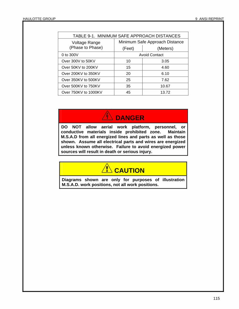
HAULOTTE GROUP 9 ANSI REPRINT
115
TABLE 9-1. MINIMUM SAFE APPROACH DISTANCES Minimum Safe Approach Distance Voltage Range
(Phase to Phase) (Feet) (Meters)
0 to 300V Avoid Contact
Over 300V to 50KV 10 3.05
Over 50KV to 200KV 15 4.60
Over 200KV to 350KV 20 6.10
Over 350KV to 500KV 25 7.62
Over 500KV to 750KV 35 10.67
Over 750KV to 1000KV 45 13.72
DANGER DO NOT allow aerial work platform, personnel, or conductive materials inside prohibited zone. Maintain M.S.A.D from all energized lines and parts as well as those shown. Assume all electrical parts and wires are energized unless known otherwise. Failure to avoid energized power sources will result in death or serious injury.
CAUTION Diagrams shown are only for purposes of illustration M.S.A.D. work positions, not all work positions.

HAULOTTE GROUP 9 ANSI REPRINT
116
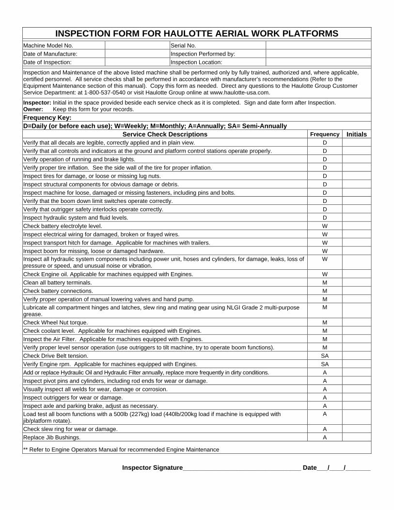
INSPECTION FORM FOR HAULOTTE AERIAL WORK PLATFORMS Machine Model No. Serial No.
Date of Manufacture: Inspection Performed by:
Date of Inspection: Inspection Location:
Inspection and Maintenance of the above listed machine shall be performed only by fully trained, authorized and, where applicable, certified personnel. All service checks shall be performed in accordance with manufacturer’s recommendations (Refer to the Equipment Maintenance section of this manual). Copy this form as needed. Direct any questions to the Haulotte Group Customer Service Department: at 1-800-537-0540 or visit Haulotte Group online at www.haulotte-usa.com.
Inspector: Initial in the space provided beside each service check as it is completed. Sign and date form after Inspection. Owner: Keep this form for your records.
Frequency Key: D=Daily (or before each use); W=Weekly; M=Monthly; A=Annually; SA= Semi-Annually
Service Check Descriptions Frequency Initials Verify that all decals are legible, correctly applied and in plain view. D Verify that all controls and indicators at the ground and platform control stations operate properly. D Verify operation of running and brake lights. D Verify proper tire inflation. See the side wall of the tire for proper inflation. D Inspect tires for damage, or loose or missing lug nuts. D Inspect structural components for obvious damage or debris. D Inspect machine for loose, damaged or missing fasteners, including pins and bolts. D Verify that the boom down limit switches operate correctly. D Verify that outrigger safety interlocks operate correctly. D Inspect hydraulic system and fluid levels. D Check battery electrolyte level. W Inspect electrical wiring for damaged, broken or frayed wires. W Inspect transport hitch for damage. Applicable for machines with trailers. W Inspect boom for missing, loose or damaged hardware. W Inspect all hydraulic system components including power unit, hoses and cylinders, for damage, leaks, loss of pressure or speed, and unusual noise or vibration.
W
Check Engine oil. Applicable for machines equipped with Engines. W Clean all battery terminals. M Check battery connections. M Verify proper operation of manual lowering valves and hand pump. M Lubricate all compartment hinges and latches, slew ring and mating gear using NLGI Grade 2 multi-purpose grease.
M
Check Wheel Nut torque. M Check coolant level. Applicable for machines equipped with Engines. M Inspect the Air Filter. Applicable for machines equipped with Engines. M Verify proper level sensor operation (use outriggers to tilt machine, try to operate boom functions). M Check Drive Belt tension. SA Verify Engine rpm. Applicable for machines equipped with Engines. SA Add or replace Hydraulic Oil and Hydraulic Filter annually, replace more frequently in dirty conditions. A Inspect pivot pins and cylinders, including rod ends for wear or damage. A Visually inspect all welds for wear, damage or corrosion. A Inspect outriggers for wear or damage. A Inspect axle and parking brake, adjust as necessary. A Load test all boom functions with a 500lb (227kg) load (440lb/200kg load if machine is equipped with jib/platform rotate).
A
Check slew ring for wear or damage. A Replace Jib Bushings. A
** Refer to Engine Operators Manual for recommended Engine Maintenance
Inspector Signature_________________________________ Date___/____/_______

Distributed by:
125 Taylor Parkway Archbold, Ohio 43502
Phone (800) 537-0540 (419) 445-8915 Fax (419) 445-0367 www.haulotte-usa.com B33-01-0104 Rev. 4. 45XA HLA 16 PX Operator’s & Maintenance Manual - August 2012