Embed Size (px)
Citation preview
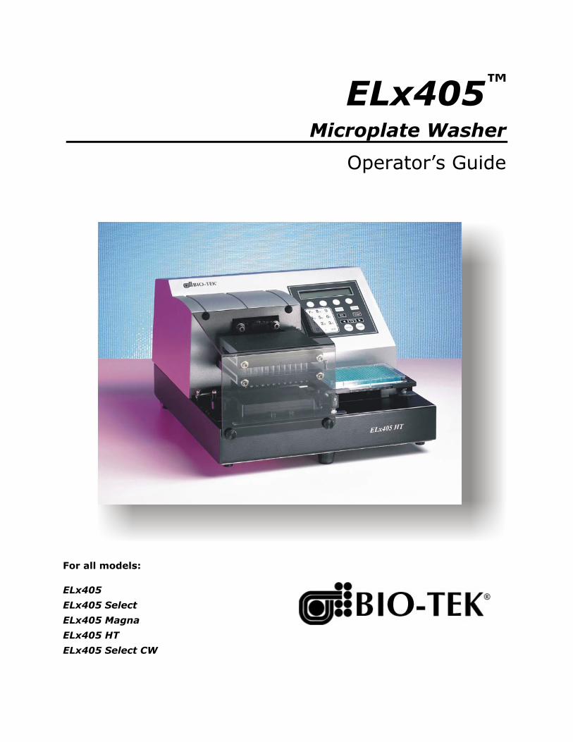
ELx405™ Microplate Washer
Operator’s Guide
For all models:
ELx405
ELx405 Select
ELx405 Magna
ELx405 HT
ELx405 Select CW

.
ELx405™ Microplate Washer Operator’s Guide
January 2005 2005 7101000 Revision I Bio-Tek Instruments, Inc.

ii | Preface
Bio-Tek Instruments, Inc.
Notices | iii
Notices
Bio-Tek Instruments, Inc.
P.O. Box 998, Highland Park
Winooski, Vermont 05404-0998 USA
All Rights Reserved
© 2005, Bio-Tek Instruments, Incorporated. No part of this publication may be reproduced, transcribed, or transmitted in any form, or by any means electronic or mechanical, including photocopying and recording, for any purpose other than the purchaser’s use without written permission of Bio-Tek Instruments, Inc.
Trademarks
Bio-Tek is a registered trademark, and ELx405, Bio-Stack, and Ultrasonic Advantage are trademarks of Bio-Tek Instruments, Inc. Microsoft, Windows, and the Windows logo are registered trademarks of Microsoft Corporation in the United States and other countries. All other trademarks are the property of their respective holders.
Restrictions and Liabilities
Information in this document is subject to change and does not represent a commitment by Bio-Tek Instruments, Inc. Changes made to the information in this document will be incorporated in new editions of the publication. Bio-Tek assumes no responsibility for the use or reliability of software or equipment that is not supplied by Bio-Tek or its affiliated dealers.
ELx405 Operator's Guide

iv | Preface
Bio-Tek Instruments, Inc.
Table of Contents | v
Table of Contents
Notices .....................................................................................iii
Table of Contents ......................................................................v
List of Figures .........................................................................xii
Contact Information...............................................................xiii
Customer Service and Sales........................................................................................ xiii
Service/TAC................................................................................................................. xiii
European Coordination Center.................................................................................. xiii
Document Conventions ..........................................................xiv
Revision History ......................................................................xv
Intended Use Statement ...................................................... xviii
Quality Control ..................................................................... xviii
Repackaging and Shipping ................................................... xviii
Warnings................................................................................xix
Hazards and Precautions........................................................xix
Hazards ..........................................................................................................................xix
Precautions......................................................................................................................xx
Directive 89/336/EEC: Electromagnetic Compatibility........................................xxii
Directive 73/23/EEC: Low Voltage (Safety)...........................................................xxii
Directive 2002/96/EC: Waste Electrical and Electronic Equipment ...................xxii
Directive 98/79/EC: In Vitro Diagnostics (some models)................................... xxiii
Electromagnetic Interference and Susceptibility.................. xxiv
USA FCC CLASS A.................................................................................................... xxiv
Canadian Department of Communications Class A............................................. xxiv
User Safety........................................................................... xxiv
Safety Symbols ..................................................................... xxv
ELx405 Operator's Guide
vi | Preface
Warranty............................................................................. xxvii
Bio-Tek Instruments Warranty Policy ................................................................... xxvii
Hardware Warranty ................................................................................................. xxvii
Registration Card ............................................................... xxviii
Registration Online ............................................................ xxviii
Chapter 1: Introduction............................................................1
Introducing the ELx405................................................................................................... 2
ELx405 Washer Variations.............................................................................................. 3
Compatibility With the Bio-Stack System .................................................................... 4
Hardware Features .......................................................................................................... 6
Software Features............................................................................................................. 7
Package Contents ............................................................................................................. 8
Optional Accessories ....................................................................................................... 9
Specifications .................................................................................................................. 10
Performance Specifications........................................................................................... 11
Technical Support .......................................................................................................... 12
Phone Support ......................................................................................................... 13
Electronic Communication..................................................................................... 13
Facsimile Support .................................................................................................... 13
Written Communication......................................................................................... 13
Shipping Address .................................................................................................... 13
Applications Support .................................................................................................... 14
Phone Support ......................................................................................................... 14
Electronic Communication..................................................................................... 14
Chapter 2: Installation ...........................................................15
Unpacking and Inspecting the Instrument ................................................................ 16
To unpack the washer and its accessories............................................................ 16
Unpacking the Valve Module................................................................................ 19
Removing the Manifold Shipping Bracket ................................................................. 21
Setting Up the Washer................................................................................................... 22
Operating Environment.......................................................................................... 22
Bio-Tek Instruments, Inc.
Table of Contents | vii
Installing the Microplate Carrier........................................................................... 22
Connecting the Tubes and Bottles......................................................................... 26
Attaching the Mist Shield....................................................................................... 33
Connecting the Power Cord................................................................................... 34
Serial Port for Communication With Other Devices .......................................... 34
Verifying Performance .................................................................................................. 35
Installation of the Washer for Operation With the Bio-Stack .................................. 36
Repackaging and Shipping........................................................................................... 37
Before Repackaging the Instrument ..................................................................... 38
Repackaging the ELx405 and Its Accessories ...................................................... 39
Repackaging the External Valve Module (if equipped)..................................... 39
Chapter 3: Operation..............................................................41
ELx405 Front Panel ........................................................................................................ 42
Keypad Description ....................................................................................................... 43
Entering Program Names ............................................................................................. 44
System Startup................................................................................................................ 45
Main Menu...................................................................................................................... 46
Programs ......................................................................................................................... 47
Operation With the Bio-Stack....................................................................................... 48
General Usage Guidelines ............................................................................................ 49
Before Running Any Program ............................................................................... 49
Maintenance ............................................................................................................. 50
Programming Considerations ............................................................................... 51
Wash ................................................................................................................................ 52
Run Wash Program ................................................................................................. 52
Define Wash Program............................................................................................. 53
Edit Wash Program ................................................................................................. 71
Copy Wash Program............................................................................................... 71
Delete Wash Program ............................................................................................. 72
Prime................................................................................................................................ 73
Run Prime Program ................................................................................................ 73
Define Prime Program ............................................................................................ 74
ELx405 Operator's Guide
viii | Preface
Recommended Prime and Low Flow Prime Volumes....................................... 76
Edit Prime Program ................................................................................................ 76
Copy Prime Program .............................................................................................. 77
Delete Prime Program............................................................................................. 77
Default Prime Program: Prime_200 ...................................................................... 78
Default Prime Program: Prime_CW ..................................................................... 78
Dispense .......................................................................................................................... 79
Run Dispense Program........................................................................................... 79
Define Dispense Program ...................................................................................... 80
Edit Dispense Program........................................................................................... 81
Copy Dispense Program......................................................................................... 81
Delete Dispense Program....................................................................................... 82
Aspiration ....................................................................................................................... 83
Run Aspiration Program ........................................................................................ 83
Define Aspiration Program.................................................................................... 84
Edit Aspiration Program ........................................................................................ 84
Copy Aspiration Program...................................................................................... 85
Delete Aspiration Program .................................................................................... 85
Soak.................................................................................................................................. 86
Define Soak Program .............................................................................................. 86
Edit Soak Program................................................................................................... 86
Copy Soak Program ................................................................................................ 87
Delete Soak Program............................................................................................... 87
Linking Programs .......................................................................................................... 88
Run Link Program................................................................................................... 88
Define Link Program............................................................................................... 89
Delete Link Program............................................................................................... 90
Setup Utilities ................................................................................................................. 91
RS-232 Settings (RS232) .......................................................................................... 91
Sensor System (SENSOR) ....................................................................................... 91
Adjust Utility (ADJUST)......................................................................................... 92
Park Utility (PARK)................................................................................................. 93
Bio-Stack Utilities (BIOSTACK) ............................................................................ 93
Bio-Tek Instruments, Inc.
Table of Contents | ix
Delay After Dispense (DISP).................................................................................. 94
Plate Clearance Height (PLATE)........................................................................... 94
Vacuum Dissipation Delay (VACUUM).............................................................. 94
Manifold Selection (MANIFOLD)......................................................................... 95
ELx405 Washer Menu Maps......................................................................................... 96
Main Menu (DEFINE function path for Create and Edit) ................................. 97
Main Menu (DEFINE function path for Copy and Delete) ............................... 98
Main Menu (RUN function path).......................................................................... 99
Main Menu (MAINT, UTIL function path) ....................................................... 100
Chapter 4: Preventive Maintenance......................................101
Overview....................................................................................................................... 102
Schedule.................................................................................................................. 102
Recommended Maintenance Schedule ..................................................................... 103
Required Materials....................................................................................................... 104
Warnings & Precautions ............................................................................................. 105
Maintenance Programs ............................................................................................... 106
Prime Programs............................................................................................................ 107
Rinse/Soak the Fluid Path.......................................................................................... 109
Daily Maintenance ................................................................................................ 109
Overnight/Multi-Day Maintenance ................................................................... 111
Clean Components....................................................................................................... 114
Periodic Maintenance ........................................................................................... 114
Decontaminate the Washer......................................................................................... 128
Decon Procedure for External Surfaces of the Instrument .............................. 129
Decon Procedure for Tubing and Manifold....................................................... 130
Alternate Decontamination Procedure for Tubing and Manifold.................. 132
Prepare for Storage or Shipment................................................................................ 134
Long_Shutdown .................................................................................................... 134
Storing the Washer ................................................................................................ 135
Replace Components................................................................................................... 136
Replacing the O-Rings and Channel-End Seals ................................................ 136
ELx405 Operator's Guide
x | Preface
Chapter 5: Performance Verification/Qualification Tests .....139
Overview....................................................................................................................... 140
Verification Schedule................................................................................................... 141
Installation Qualification (IQ) .................................................................................... 142
Operational Qualification (OQ) ................................................................................. 142
Performance Qualification (PQ)................................................................................. 143
System and Checksum Tests ...................................................................................... 144
System Self Test ..................................................................................................... 144
Checksum Test....................................................................................................... 145
Liquid Tests .................................................................................................................. 146
Evacuation Efficiency Test (Overview) .............................................................. 146
Dispense Precision Test (Overview) ................................................................... 146
Valve Module Test (Overview) ........................................................................... 147
Which Tests to Perform?....................................................................................... 147
Materials ................................................................................................................. 148
Evacuation Efficiency Test (96)............................................................................ 150
Dispense Precision Test (96)................................................................................. 153
Evacuation Efficiency Test (192).......................................................................... 157
Dispense Precision Test (192)............................................................................... 160
Worksheets ............................................................................................................. 164
Appendix A: Troubleshooting ...............................................171
Overview....................................................................................................................... 172
Troubleshooting Checklist .................................................................................. 172
Troubleshooting Charts .............................................................................................. 173
Washer Start-Up .................................................................................................... 173
Fluid Aspiration..................................................................................................... 175
Fluid Delivery ........................................................................................................ 178
Fluid Leakage......................................................................................................... 181
Microplate Carrier Movement............................................................................. 182
Washer Manifold Movement............................................................................... 182
Microplate Scratches ............................................................................................. 183
Bio-Tek Instruments, Inc.
Table of Contents | xi
Appendix B: Error Codes.......................................................185
Error Codes ................................................................................................................... 186
Bio-Stack Errors (Overview) ................................................................................ 186
General Errors .............................................................................................................. 187
Fatal Errors.................................................................................................................... 200
Bio-Stack Errors............................................................................................................ 203
Appendix C: Chemical Compatibility .....................................205
Components and Materials Composition................................................................. 206
Appendix D: Default Programs .............................................207
Default Programs ......................................................................................................... 208
Appendix E: Changing the Manifolds ....................................209
Changing Manifolds in HT Models With the 96-Tube Manifold.......................... 210
Index ....................................................................................213
ELx405 Operator's Guide
xii | Preface
List of Figures
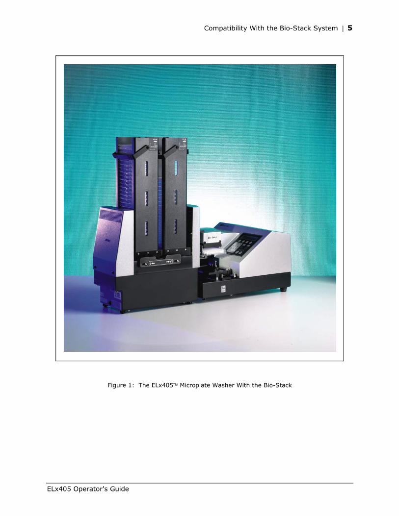
Figure 1: The ELx405™ Microplate Washer With the Bio-Stack ........................................................ 5
Figure 2: Removing the Inner Shipping Box ....................................................................................... 17
Figure 3: Removing the Carrier and Other Accessories .................................................................... 17
Figure 4: Removing the End Caps ........................................................................................................ 18
Figure 5: Manifold Shipping Bracket ................................................................................................... 18
Figure 6: Removing the Valve Module From the Shipping Container............................................ 20
Figure 7: Removing the Wire Holders, Supply Bottles, and Other Accessories ........................... 20
Figure 8: Removing and Storing the Manifold Shipping Bracket .................................................... 21
Figure 9: Installing the Microplate Carrier for the ELx405 Model ................................................... 23
Figure 10: Installing the Microplate Carrier for the Select, Select CW, and all HT Models ......... 24
Figure 11: Installing the Microplate and Magnet Plate Carriers for the Magna Model ................ 25
Figure 12: Rear Panel .............................................................................................................................. 27
Figure 13: Washer With Vacuum Pump and Waste Tubing Connections...................................... 29
Figure 14: Washer With Supply Tubing Connections (Without External Valve Module) ........... 31
Figure 15: Washer With External Valve Module ................................................................................ 32
Figure 16: Attaching the Mist Shield .................................................................................................... 33
Figure 17: ELx405 Front Panel With LCD and Keypad ..................................................................... 42
Figure 18: Dispense and Aspirate Heights for the ELx405 and Magna Models ............................ 68
Figure 19: Dispense and Aspirate Heights for the Select, Select CW, and HT2/HTV2 Models With Dual/96 Manifold ........................................................................................................... 69
Figure 20: Dispense and Aspirate Heights for the HT Model .......................................................... 70
Figure 21: Using the Adjust Utility....................................................................................................... 93
Figure 22: Position of the Transport Arm on the Plate Carrier....................................................... 116
Figure 23: Removing the Screws and Washers From the Transport Arm .................................... 117
Figure 24: The Transport Arm Removed From the Carrier ............................................................ 117
Figure 25: Carrier and Manifold Placement in the ELx405 Model................................................. 120
Figure 26: Carrier and Manifold Placement in the Select, Select CW, and HT Models .............. 121
Figure 27: Carrier and Manifold Placement in the Magna Model ................................................. 122
Figure 28: Cleaning the Fluid Inlet Filter........................................................................................... 127
Figure 29: Replacing the Channel-End Seals..................................................................................... 137
Figure 30: Storing the 96- or 192-Tube Dual Manifold in the Shipping Case............................... 212
Bio-Tek Instruments, Inc.
Contact Information | xiii
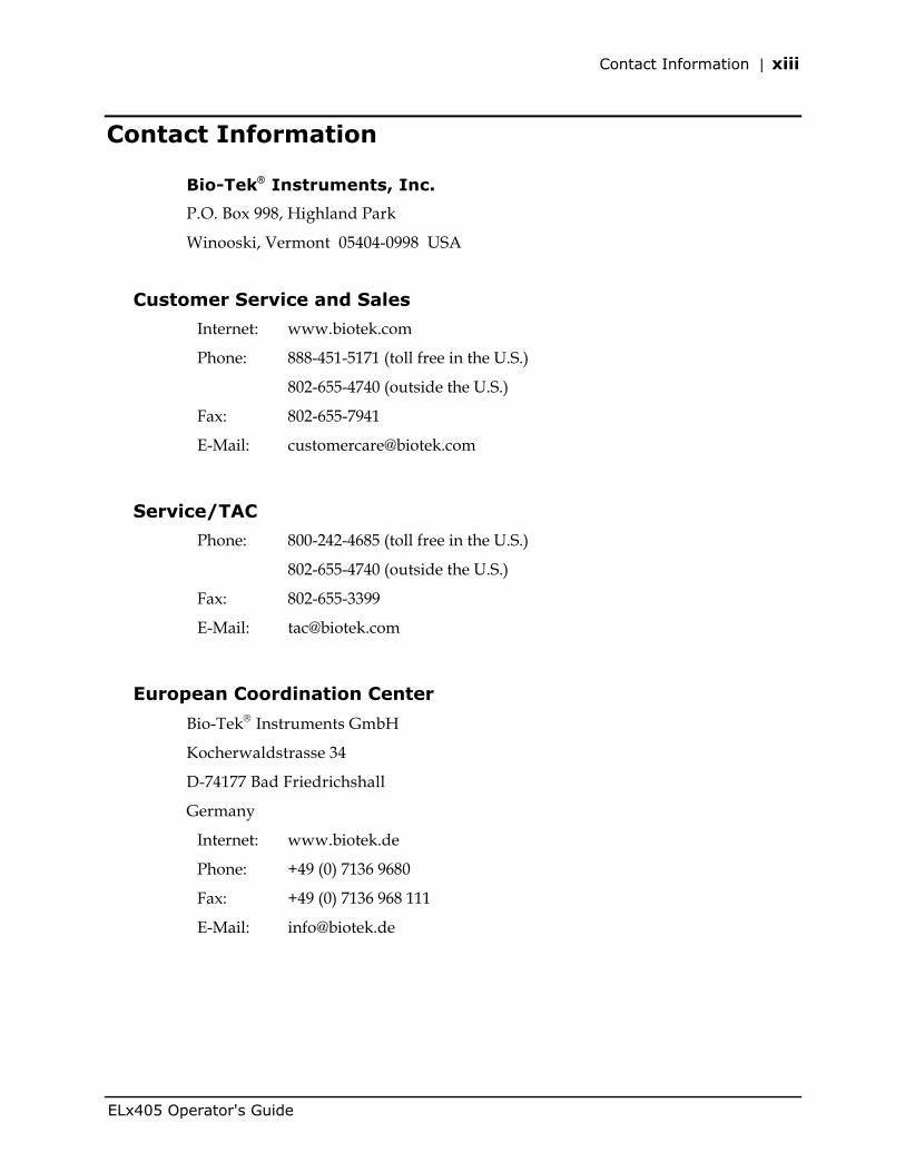
Contact Information
Bio-Tek Instruments, Inc.
P.O. Box 998, Highland Park
Winooski, Vermont 05404-0998 USA
Customer Service and Sales
Internet: www.biotek.com
Phone: 888-451-5171 (toll free in the U.S.)
802-655-4740 (outside the U.S.)
Fax: 802-655-7941
E-Mail: [email protected]
Service/TAC
Phone: 800-242-4685 (toll free in the U.S.)
802-655-4740 (outside the U.S.)
Fax: 802-655-3399
E-Mail: [email protected]
European Coordination Center
Bio-Tek Instruments GmbH
Kocherwaldstrasse 34
D-74177 Bad Friedrichshall
Germany
Internet: www.biotek.de
Phone: +49 (0) 7136 9680
Fax: +49 (0) 7136 968 111
E-Mail: [email protected]
ELx405 Operator's Guide
xiv | Preface
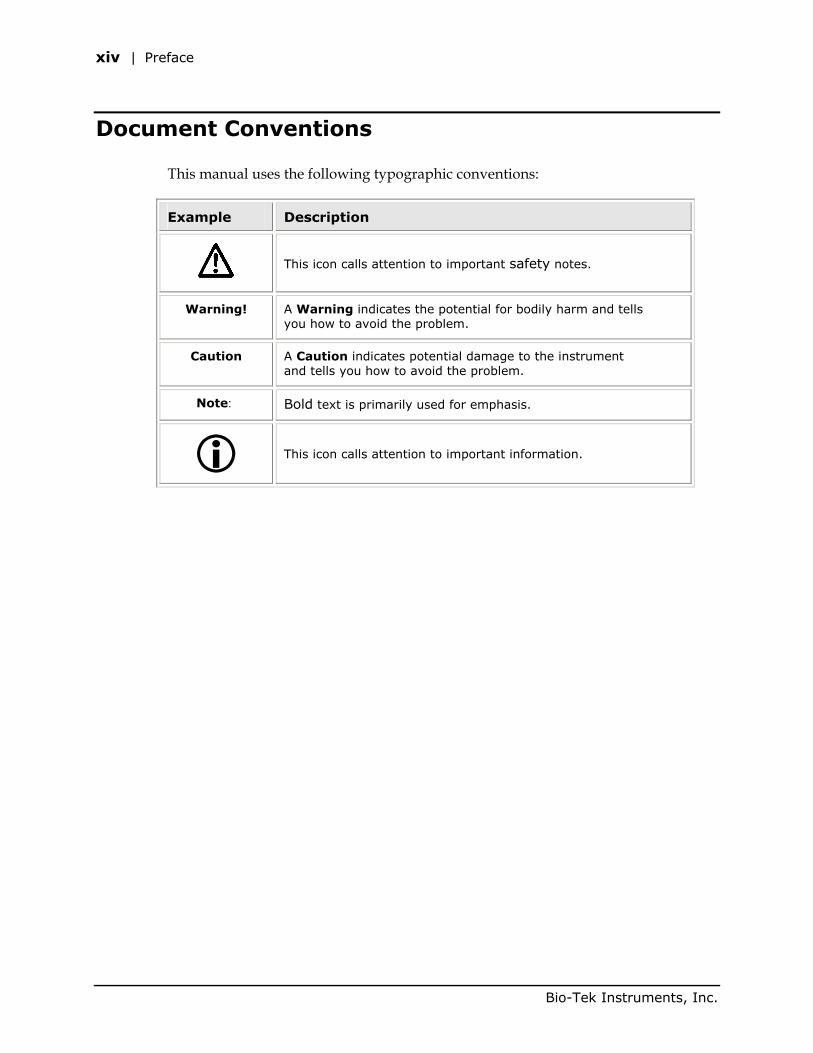
Document Conventions
This manual uses the following typographic conventions:
Example Description
This icon calls attention to important safety notes.
Warning! A Warning indicates the potential for bodily harm and tells you how to avoid the problem.
Caution A Caution indicates potential damage to the instrument and tells you how to avoid the problem.
Note: Bold text is primarily used for emphasis.
This icon calls attention to important information.
Bio-Tek Instruments, Inc.
Revision History | xv
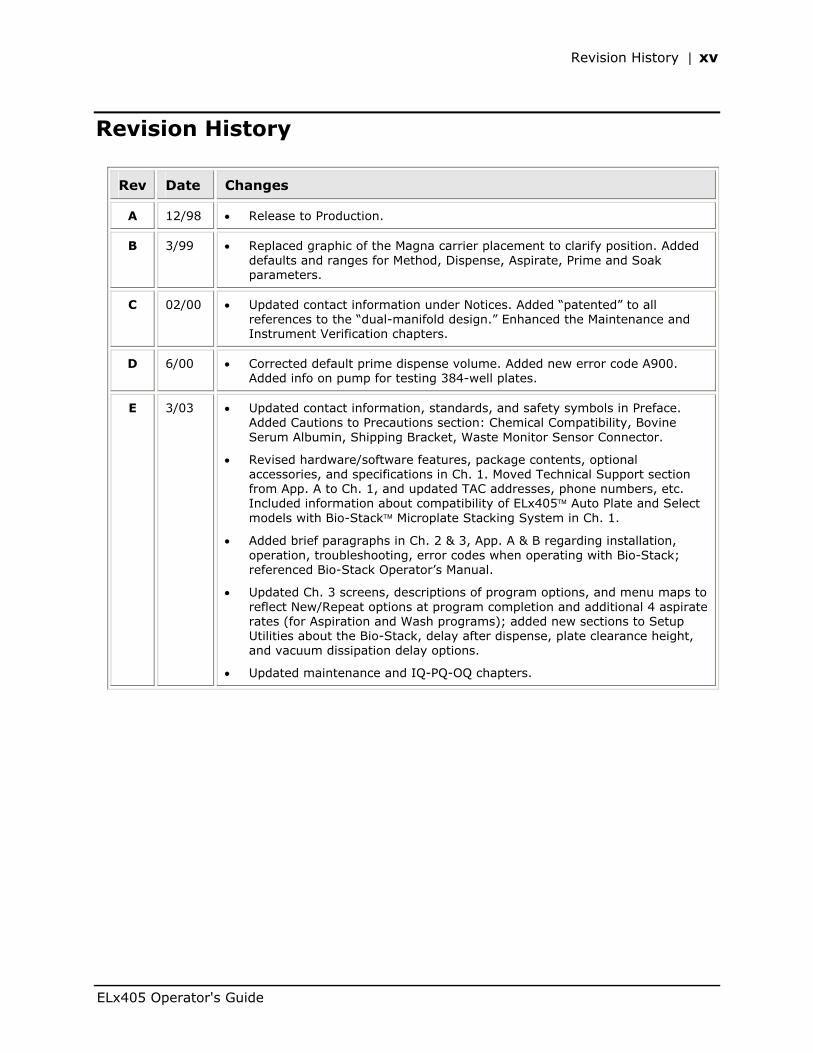
Revision History
Rev Date Changes
A 12/98 • Release to Production.
B 3/99 • Replaced graphic of the Magna carrier placement to clarify position. Added defaults and ranges for Method, Dispense, Aspirate, Prime and Soak parameters.
C 02/00 • Updated contact information under Notices. Added “patented” to all references to the “dual-manifold design.” Enhanced the Maintenance and Instrument Verification chapters.
D 6/00 • Corrected default prime dispense volume. Added new error code A900. Added info on pump for testing 384-well plates.
E 3/03 • Updated contact information, standards, and safety symbols in Preface. Added Cautions to Precautions section: Chemical Compatibility, Bovine Serum Albumin, Shipping Bracket, Waste Monitor Sensor Connector.
• Revised hardware/software features, package contents, optional accessories, and specifications in Ch. 1. Moved Technical Support section from App. A to Ch. 1, and updated TAC addresses, phone numbers, etc. Included information about compatibility of ELx405 Auto Plate and Select models with Bio-Stack Microplate Stacking System in Ch. 1.
• Added brief paragraphs in Ch. 2 & 3, App. A & B regarding installation, operation, troubleshooting, error codes when operating with Bio-Stack; referenced Bio-Stack Operator’s Manual.
• Updated Ch. 3 screens, descriptions of program options, and menu maps to reflect New/Repeat options at program completion and additional 4 aspirate rates (for Aspiration and Wash programs); added new sections to Setup Utilities about the Bio-Stack, delay after dispense, plate clearance height, and vacuum dissipation delay options.
• Updated maintenance and IQ-PQ-OQ chapters.
ELx405 Operator's Guide
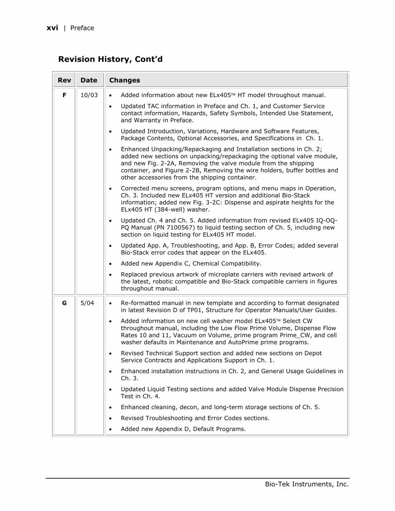
xvi | Preface
Revision History, Cont’d
Rev Date Changes
F 10/03 • Added information about new ELx405 HT model throughout manual.
• Updated TAC information in Preface and Ch. 1, and Customer Service contact information, Hazards, Safety Symbols, Intended Use Statement, and Warranty in Preface.
• Updated Introduction, Variations, Hardware and Software Features, Package Contents, Optional Accessories, and Specifications in Ch. 1.
• Enhanced Unpacking/Repackaging and Installation sections in Ch. 2; added new sections on unpacking/repackaging the optional valve module, and new Fig. 2-2A, Removing the valve module from the shipping container, and Figure 2-2B, Removing the wire holders, buffer bottles and other accessories from the shipping container.
• Corrected menu screens, program options, and menu maps in Operation, Ch. 3. Included new ELx405 HT version and additional Bio-Stack information; added new Fig. 3-2C: Dispense and aspirate heights for the ELx405 HT (384-well) washer.
• Updated Ch. 4 and Ch. 5. Added information from revised ELx405 IQ-OQ-PQ Manual (PN 7100567) to liquid testing section of Ch. 5, including new section on liquid testing for ELx405 HT model.
• Updated App. A, Troubleshooting, and App. B, Error Codes; added several Bio-Stack error codes that appear on the ELx405.
• Added new Appendix C, Chemical Compatibility.
• Replaced previous artwork of microplate carriers with revised artwork of the latest, robotic compatible and Bio-Stack compatible carriers in figures throughout manual.
G 5/04 • Re-formatted manual in new template and according to format designated in latest Revision D of TP01, Structure for Operator Manuals/User Guides.
• Added information on new cell washer model ELx405 Select CW throughout manual, including the Low Flow Prime Volume, Dispense Flow Rates 10 and 11, Vacuum on Volume, prime program Prime_CW, and cell washer defaults in Maintenance and AutoPrime prime programs.
• Revised Technical Support section and added new sections on Depot Service Contracts and Applications Support in Ch. 1.
• Enhanced installation instructions in Ch. 2, and General Usage Guidelines in Ch. 3.
• Updated Liquid Testing sections and added Valve Module Dispense Precision Test in Ch. 4.
• Enhanced cleaning, decon, and long-term storage sections of Ch. 5.
• Revised Troubleshooting and Error Codes sections.
• Added new Appendix D, Default Programs.
Bio-Tek Instruments, Inc.
Revision History | xvii
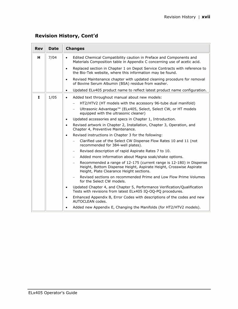
Revision History, Cont’d
Rev Date Changes
H 7/04 • Edited Chemical Compatibility caution in Preface and Components and Materials Composition table in Appendix C concerning use of acetic acid.
• Replaced section in Chapter 1 on Depot Service Contracts with reference to the Bio-Tek website, where this information may be found.
• Revised Maintenance chapter with updated cleaning procedure for removal of Bovine Serum Albumin (BSA) residue from washer.
• Updated ELx405 product name to reflect latest product name configuration.
I 1/05 • Added text throughout manual about new models:
− HT2/HTV2 (HT models with the accessory 96-tube dual manifold)
− Ultrasonic Advantage™ (ELx405, Select, Select CW, or HT models equipped with the ultrasonic cleaner)
• Updated accessories and specs in Chapter 1, Introduction.
• Revised artwork in Chapter 2, Installation, Chapter 3, Operation, and Chapter 4, Preventive Maintenance.
• Revised instructions in Chapter 3 for the following:
− Clarified use of the Select CW Dispense Flow Rates 10 and 11 (not recommended for 384-well plates).
− Revised description of rapid Aspirate Rates 7 to 10.
− Added more information about Magna soak/shake options.
− Recommended a range of 12-175 (current range is 12-180) in Dispense Height, Bottom Dispense Height, Aspirate Height, Crosswise Aspirate Height, Plate Clearance Height sections.
− Revised sections on recommended Prime and Low Flow Prime Volumes for the Select CW models.
• Updated Chapter 4, and Chapter 5, Performance Verification/Qualification Tests with revisions from latest ELx405 IQ-OQ-PQ procedures.
• Enhanced Appendix B, Error Codes with descriptions of the codes and new AUTOCLEAN codes.
• Added new Appendix E, Changing the Manifolds (for HT2/HTV2 models).
ELx405 Operator's Guide
xviii | Preface
Intended Use Statement
• The ELx405 Microplate Washer provides microplate priming, washing, dispensing, and aspiration for ELISA™, fluorescence and chemiluminescence immunoassays, cellular and agglutination assays.
• The washer can operate as a stand-alone instrument or with standard robotic systems, such as Bio-Tek’s Bio-Stack Microplate Stacker.
• The intended use of this instrument is dependent on the instrument’s rear panel label. If there is an IVD label, then the instrument may be used for clinical, research and development, or other non-clinical purposes. If there is no such label, then the instrument may only be used for research and development, or for other non-clinical purposes.
Quality Control
It is considered good laboratory practice to run laboratory samples according to instructions and specific recommendations included in the assay package insert for the test to be conducted. Failure to conduct Quality Control checks could result in erroneous test data.
Repackaging and Shipping
Important! If you need to ship the instrument to Bio-Tek for service or repair, contact Bio-Tek for a Return Materials Authorization (RMA) number, and be sure to use the original packing. Other forms of commercially available packing are not recommended and can void the warranty. If the original packing materials have been damaged or lost, contact Bio-Tek for replacement packing.
Bio-Tek Instruments, Inc.
Warnings | xix
Warnings
Operate the instrument on a flat surface and away from excessive humidity.
When operated in a safe environment according to the instructions in this document, there are no known hazards associated with the ELx405. However, the operator should be aware of certain situations that could result in serious injury; these may vary depending on the instrument model.
Hazards and Precautions
Hazards
Warning! Power Rating. The ELx405’s power cord must be connected to a power receptacle that provides voltage and current within the specified rating for the system. Use of an incompatible power receptacle may produce electrical shock and fire hazards.
Warning! Electrical Grounding. Never use a two-prong plug adapter to connect primary power to the ELx405. Use of a two-prong adapter disconnects the utility ground, creating a severe shock hazard. Always connect the power cord directly to a three-prong receptacle with a functional ground.
Warning! Internal Voltage. Always turn off the power switch and unplug the power cord before cleaning the outer surface of the instrument.
Warning! Potential Biohazards. Some assays or specimens may pose a biohazard. Adequate safety precautions should be taken as outlined in the assay’s package insert. Always wear safety glasses and appropriate protective equipment, such as chemically resistant rubber gloves and apron.
Warning! Ultrasonic Energy. Ultrasonic energy is present in the ultrasonic cleaner reservoir when AUTOCLEAN programs are running (Ultrasonic Advantage™ models only). Avoid putting your fingers in the bath. Ultrasonic energy can be destructive to human tissue.
ELx405 Operator's Guide
xx | Preface
Hazards, Cont’d
Warning! Liquids. Avoid spilling liquids on the washer; fluid seepage into internal components creates a potential for shock hazard. Wipe up all spills immediately. Do not operate the instrument if internal components have been exposed to fluid.
Warning! Software Quality Control. The operator must follow the manufacturer’s assay package insert when modifying software parameters and establishing wash methods, using the washer’s onboard software.
Precautions
The following precautions are provided to help avoid damage to the instrument:
Caution: Service. Only Bio-Tek authorized service personnel should service the instrument. Only qualified technical personnel should perform troubleshooting and service procedures on internal components.
Caution: Environmental Conditions. Do not expose the instrument to temperature extremes. For proper operation, ambient temperatures should remain between 15°-30°C. Performance may be adversely affected if temperatures fluctuate above or below this range. Storage temperature limits are broader (see Chapter 4, Preventive Maintenance).
Caution: Sodium Hypochlorite. Do not expose any part of the instrument to the recommended diluted sodium hypochlorite solution (bleach) for more than 20 minutes. Prolonged contact may damage the instrument surfaces. Be certain to rinse and thoroughly wipe all surfaces.
Caution: Chemical Compatibility - Washers. Some chemicals may cause irreparable damage to washers. The following chemicals have been deemed safe for use in washers: buffer solutions (such as PBS), saline, surfactants, deionized water, 70% ethyl, isopropyl, or methyl alcohol, 40% formaldehyde, and 20% sodium hydroxide. Never use DMSO or other organic solvents. These chemicals may cause severe damage to the instrument. Refer to Appendix C, Chemical Compatibility. Use of wash buffers containing acetic acid is limited to washers upgraded with PN 68098 Teflon® valves. Contact Bio-Tek for upgrade information and prior to using other questionable chemicals.
Bio-Tek Instruments, Inc.
Hazards and Precautions | xxi
Precautions, Cont’d
Caution: Wash Buffer Solution. Although many precautions have been taken to ensure that the instrument is as corrosion-proof as possible, the washer is not sealed and liquids can seep into sensitive components. Make sure that any spilled wash buffer solution is wiped off the washer. Prolonged exposure to salt solution may corrode parts of the microplate carrier, movement rail, springs, and other hardware.
Caution: Bovine Serum Albumin. Solutions containing proteins, such as bovine serum albumin (BSA), will compromise the washer’s performance over time unless a strict maintenance protocol is adhered to. See Chapter 4, Preventive Maintenance for cleaning instructions regarding BSA.
Caution: Shipping Bracket. The manifold shipping bracket must be removed prior to operating the ELx405, and reinstalled before repackaging the washer for shipment. See Chapter 2, Installation, for instructions.
Caution: Waste Sensor Port. The port on the back of all ELx405 Washers for the waste sensor is the same type as the 24-VDC power connector on some other Bio-Tek products (like the Bio-Stack Microplate Stacker). If an external 24-VDC power supply is plugged into this waste sensor port, it will permanently damage components on the PCB inside the ELx405.
Caution: High Flow Pump Installation. DO NOT plug the High Flow vacuum pump cable into a wall outlet! Use the adapter provided with the pump to connect the pump to the accessory outlet on the back of the washer. See Chapter 2, Installation, for instructions.
Caution: Warranty. Failure to follow preventive maintenance protocols may void the warranty. See Chapter 4, Preventive Maintenance.
Caution: Disposal. This instrument contains printed circuit boards and wiring with lead solder. Dispose of the instrument according to Directive 2002/96/EC, “on waste electrical and electronic equipment (WEEE).”
Important! Do not plug an external 24-VDC power supply into the waste sensor port on the ELx405!
ELx405 Operator's Guide
xxii | Preface
Bio-Tek Instruments, Inc.
Based on the testing described below and information contained herein, this instrument bears the CE mark.
Directive 89/336/EEC:Electromagnetic Compatibility
Emissions - CLASS A
EN 61326-1:1998
CISPR 16-1:1997 and CISPR-2:1999
Immunity
EN 61326-1:1998
EN 61000-4-2:1998 Electrostatic Discharge
EN 61000-4-3:1998 Radiated EM Fields
EN 61000-4-4:1995 Electrical Fast Transient/Burst
EN 61000-4-5:1995 Surge Immunity
EN 61000-4-6:1996 Conducted Disturbances
EN 61000-4-11:1994 Voltage Dips, Short Interruptions and Variations
Directive 73/23/EEC: Low Voltage (Safety)
EN 61010-1:2001
"Safety requirement for Electrical Equipment for Measurement, Control and Laboratory Use, Part 1: General requirements.”
Directive 2002/96/EC: Waste Electrical and Electronic Equipment
Disposal Notice
This instrument contains printed circuit boards and wiring with lead solder. Dispose of the instrument according to Directive 2002/96/EC, “on waste electrical and electronic equipment (WEEE).”
Hazards and Precautions | xxiii
Directive 98/79/EC: In Vitro Diagnostics (some models)
• Product registration with competent authorities
• Traceability to the U.S. National Institute of Standards and Technology (NIST):
Microplate Washers: Dispense precision and average residual volume is traceable to NIST.
Specific data for a particular serial number is available on request from Bio-Tek Instruments. See page xiii for contact information.
EN 61010-2-101:2002
Particular requirements for in vitro diagnostic (IVD) medical equipment.
ELx405 Operator's Guide
xxiv | Preface
Electromagnetic Interference and Susceptibility
USA FCC CLASS A
Warning: Changes or modifications to this unit not expressly approved by the manufacturer could void the user's authority to operate the equipment.
This equipment has been tested and found to comply with the limits for a Class A digital device, pursuant to Part 15 of the FCC Rules.
These limits are designed to provide reasonable protection against harmful interference when the equipment is operated in a commercial environment. Like all similar equipment, this equipment generates, uses, and can radiate radio frequency energy and, if not installed and used in accordance with the instruction manual, may cause harmful interference to radio communications. Operation of this equipment in a residential area is likely to cause interference, in which case the user will be required to correct the interference at his own expense.
Canadian Department of Communications Class A
This digital apparatus does not exceed Class A limits for radio emissions from digital apparatus set out in the Radio Interference Regulations of the Canadian Department of Communications.
Le present appareil numerique n'met pas du bruits radioelectriques depassant les limites applicables aux appareils numerique de la Class A prescrites dans le Reglement sur le brouillage radioelectrique edicte par le ministere des Communications du Canada.
User Safety
This device has been type tested by an independent laboratory and found to meet the requirements of the following:
• Canadian Standards Association CAN/CSA C22.2 No. 61010-1-04
“Safety Requirements for Electrical Equipment for Measurement, Control and Laboratory Use, Part 1: General Requirements.”
• Underwriters Laboratories UL 61010-1:2004
“Safety Requirements for Electrical Equipment for Measurement, Control and Laboratory Use, Part 1: General Requirements.”
Bio-Tek Instruments, Inc.

Safety Symbols | xxv
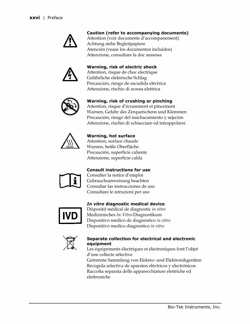
Safety Symbols
Some of these symbols may appear on the instruments:
Alternating current Courant alternatif Wechselstrom Corriente alterna Corrente alternata
Direct current Courant continu Gleichstrom Corriente continua Corrente continua
Both direct and alternating current Courant continu et courant alternatif Gleich - und Wechselstrom Corriente continua y corriente alterna Corrente continua e corrente alternata
Earth ground terminal Borne de terre Erde (Betriebserde) Borne de tierra Terra (di funzionamento)
Protective conductor terminal Borne de terre de protection Schutzleiteranschluss Borne de tierra de protección Terra di protezione
On (Supply) Marche (alimentation) Ein (Verbindung mit dem Netz) Conectado Chiuso
Off (Supply) Arrêt (alimentation) Aus (Trennung vom Netz) Desconectado Aperto (sconnessione dalla rete di alimentazione)
ELx405 Operator's Guide
xxvi | Preface
Caution (refer to accompanying documents) Attention (voir documents d’accompanement) Achtung siehe Begleitpapiere Atención (vease los documentos incluidos) Attenzione, consultare la doc annessa
Warning, risk of electric shock Attention, risque de choc electrique Gefährliche elektrische Schlag Precaución, riesgo de sacudida eléctrica Attenzione, rischio di scossa elettrica
Warning, risk of crushing or pinching Attention, risque d’écrasement et pincement Warnen, Gefahr des Zerquetschens und Klemmen Precaución, riesgo del machacamiento y sejeción Attenzione, rischio di schiacciare ed intrappolarsi
Warning, hot surface Attention, surface chaude Warnen, heiße Oberfläche Precaución, superficie caliente Attenzione, superficie calda
Consult instructions for use Consulter la notice d’emploi Gebrauchsanweisung beachten Consultar las instrucciones de uso Consultare le istruzioni per uso
In vitro diagnostic medical device Dispositif médical de diagnostic in vitro Medizinisches In-Vitro-Diagnostikum Dispositivo médico de diagnóstico in vitro Dispositivo medico diagnostico in vitro
Separate collection for electrical and electronic equipment Les équipements électriques et électroniques font l’objet d’une collecte sélective Getrennte Sammlung von Elektro- und Elektronikgeräten Recogida selectiva de aparatos eléctricos y electrónicos Raccolta separata delle apparecchiature elettriche ed elettroniche
Bio-Tek Instruments, Inc.
Warranty | xxvii
Warranty
Bio-Tek Instruments Warranty Policy
Bio-Tek grants Limited Warranties that are applied to hardware and software products manufactured by Bio-Tek Instruments, Inc. (“Bio-Tek”).
This Limited Warranty contains the entire obligation of Bio-Tek Instruments, Inc., and no other warranties, expressed, implied, or statutory, are given. Purchaser agrees to assume all liability for any damage and/or bodily injury or death that may result from the use or misuse of any instrument/software by the purchaser, his employees, agents or customers, other than the express warranty contained herein. Under no circumstances shall Bio-Tek be liable to the purchaser or any other person for any direct, incidental or consequential damages, whether rising out of breach of Warranty or otherwise. The implied warranties of merchantability and of fitness for any particular purpose are expressly excluded and do not apply to the instrument/software. This warranty shall not be changed or modified in any way without the express written permission of an officer of Bio-Tek Instruments.
Hardware Warranty
Bio-Tek warrants the hardware instrument for a period of one (1) year from the date of the product shipment from Bio-Tek against defective materials and workmanship. This warranty is limited to the original purchaser and cannot be assigned or transferred. All claims under this limited warranty must be made in writing to Bio-Tek, Attention: Service Department, or to Bio-Tek’s authorized representative. Purchaser must ship the product to Bio-Tek, postage pre-paid. Bio-Tek shall either repair or replace with new, like new, or equipment of similar condition at its option and without cost to the purchaser, any product that in Bio-Tek’s sole judgment is defective by reason of defects in the material or workmanship.
This warranty is void if the instrument has been damaged by accident or misuse, or has been damaged by abuse or negligence in the operation or maintenance of the product, including without limitation, unsafe operation, operation by untrained personnel, and failure to perform routine maintenance. This warranty is void if the instrument has been repaired or altered by persons not authorized by Bio-Tek, or if the product has had the serial number altered, effaced, or removed. This warranty is void if the instrument has not been connected, installed, or adjusted strictly in accordance with written directions furnished by Bio-Tek. Batteries, fuses, lamps, and other ‘consumable’ items used in any of the instruments are not covered by this warranty.
Bio-Tek will continue to stock parts for a minimum of five (5) years after the manufacture of any equipment has been discontinued. Parts shall include all materials, charts, instructions, diagrams, and accessories that were furnished with the standard instrument.
ELx405 Operator's Guide
xxviii | Preface
Registration Card
Once the instrument has been set up and is running successfully, please take a moment to fill out and mail the postage-paid Warranty Registration card. By sending in the registration card, you will be assured of receiving prompt information on product enhancements.
Registration Online
If you prefer, you may register your instrument online at Bio-Tek’s Web site: www.biotek.com.
Bio-Tek Instruments, Inc.
Chapter 1
Introduction
This chapter introduces the ELx405 Microplate Washer, and describes variations of the washer, hardware and software features, and technical specifications. Instructions on how to contact Bio-Tek for Technical Assistance are included on page 12.
Introducing the ELx405 ............................................................2 ELx405 Washer Variations.........................................................3 Compatibility With the Bio-Stack System.....................................4 Hardware Features...................................................................6 Software Features....................................................................7 Package Contents ....................................................................8 Optional Accessories ................................................................9 Specifications ..........................................................................10 Performance Specifications........................................................11 Technical Support ....................................................................12 Applications Support ................................................................14
2 | Chapter 1: Introduction
Introducing the ELx405
Precise, fast, and easy to use, the ELx405 is a user-programmable, fully automated microplate washer. Variations of the washer include the ELx405, Select, HT, Magna, and Select CW. Its key features include the following:
• Programmable dispense volumes, flow, and aspiration rates provide for a wide range of washing capabilities, from gentle washing for cellular assays to vigorous washing for ELISA.
• The bottom washing routine can be applied to lower the background absorbance. The crosswise aspiration routine can be utilized to reduce residual volumes.
• The ELx405 can be used to wash all microplate-based assays, including ELISA, fluorescence, chemiluminescence, RIA, DNA probes, and cellular assays.
• The intuitive menu-driven software allows you to create and store up to 75 washer programs. When you are ready to run a program, simply select the program name and follow the screen prompts. The ELx405 will then process the plate according to the program parameters.
• All ELx405 models support Wash, Prime, Dispense, and Aspirate programs. In addition, these programs can be “linked” together to run automatically.
• An optional external valve-switching module with four different supply bottles can be used with models that have been retrofitted to support the module.
• Built-in fluid flow, fluid detection, and vacuum sensing provide complete protection for unattended operation.
• Several pre-defined programs are provided to simplify preventative maintenance, which should be performed regularly to ensure optimum washer performance.
• In addition to operating on a stand-alone basis, the ELx405, Select, HT, and Select CW models are compatible with the Bio-Stack Microplate Stacker. See page 4, Compatibility With the Bio-Stack System. (The Magna model is not compatible.)
• All ELx405 models include a robot accessible carrier and can be interfaced into some standard robotic systems.
• All ELx405 models may be serially controlled using Bio-Tek’s Autowasher ActiveX component, typically for integration into automated systems.
• Models equipped with the Ultrasonic Advantage™ (ultrasonic cleaner) provide extra cleaning power by using ultrasonic pulses in a water bath to remove residue on the manifold tubes.
Bio-Tek Instruments, Inc.
ELx405 Washer Variations | 3
ELx405 Washer Variations
The ELx405 is available in the models listed below. See Figures 18-20 in Chapter 3, Operation, for illustrations of these models.
• The ELx405 is the “standard” model, used to wash 96-well microplates. It has one manifold with 96 sets of dispense and aspirate tubes.
• The ELx405 Select can be used to wash standard 96-well plates and 384-well plates. Its patented Dual-Action manifold features 96 sets of dispense and aspirate tubes that are arranged in a fixed horizontal position relative to each other but located in two separate manifolds. The two manifolds move independently of each other on the vertical axis.
• The ELx405 HT is a fast 384-well microplate washer and is ideal for high throughput washing. The washer includes the Bio-Tek patented Dual-Action manifold that has been fitted with 192 aspirate and dispense tubes, and allows overflow wash/overfill protection in 384 plates for the most demanding assays. The ELx405 HT is also available in two models that include the 96-tube Dual Action manifold as an accessory: the ELx405HT2 and ELx405HTV2 (valve module).
• The ELx405 Magna allows the use of magnets for assays that use plastic- coated metal beads as a substrate. The beads are placed in a standard 96-well microplate. A second carrier that travels beneath the microplate carrier can be fitted with a magnetic plate. When the second carrier is below the microplate, the magnet will pull the beads into the bottom of the microwells and hold them there during aspiration of the supernatant and during soaking cycles. The Magna can also be used as a standard 96-well washer.
• The ELx405 Select CW or “cell washer” incorporates all the functionality of the ELx405 Select washer with additional low flow tubing for sensitive, cell-based assays. The ELx405 Select CW software includes the standard flow rates of the ELx405 Select as well as two ultra low flow rates for a gentler washing of non-adherent cells or cell lines that are more loosely adhered to the microplate.
All models can be configured to work with the optional valve module, for users who have complex assay requirements. With the valve module attached, the user can create linked programs to automatically draw reagent from up to four separate reservoirs.
Models equipped with the Ultrasonic Advantage™ feature a built-in ultrasonic cleaner for enhanced maintenance of the manifold tubes. A stainless steel cleaning reservoir with an ultrasonic transducer bonded to the bottom of the reservoir is mounted on the washer. An AUTOCLEAN function in the onboard Utility menu enables the user to create and run ultrasonic cleaning routines using programmable parameters such as number and duration of loops, and supply sources.
Not all Select CW models support the external valve module. If you have questions about your Select CW’s compatibility with this valve module, contact Bio-Tek.
Magna models do not support the Ultrasonic Advantage™.
ELx405 Operator's Guide
4 | Chapter 1: Introduction
Compatibility With the Bio-Stack System
The ELx405, Select, HT, and Select CW models are compatible with Bio-Tek’s Bio-Stack Microplate Stacker (see Figure 1 on the following page). The basecode software of these washers has been modified so that their normal operating displays now include the Bio-Stack options. Upgrade kits are also available for customers who purchased their ELx405 and Select models before modifications to the basecode. (All HT and Select CW models support the Bio-Stack.)
Controlled serially by the ELx405, the Bio-Stack can rapidly and systematically transfer microplates one at a time to and from the washer, and includes:
• Removable stacks (one input and one output) that can hold up to 30 microplates each.
• Optional restacking of plates to maintain correct sequencing.
• The ability to continue processing a stack of plates following the aborting/failure of one plate.
• The ability to pause processing to allow the user to add more plates to the input stack or to remove some from the output stack.
If you have purchased the Bio-Stack to operate with the ELx405, Select, HT, and Select CW, refer to the Bio-Stack Operator’s Manual for instructions on configuring the washer to run with the Bio-Stack. If you are interested in purchasing the Bio-Stack, contact your local Bio-Tek dealer for more information.
Bio-Tek Instruments, Inc.
Compatibility With the Bio-Stack System | 5
Figure 1: The ELx405 Microplate Washer With the Bio-Stack
ELx405 Operator's Guide
6 | Chapter 1: Introduction
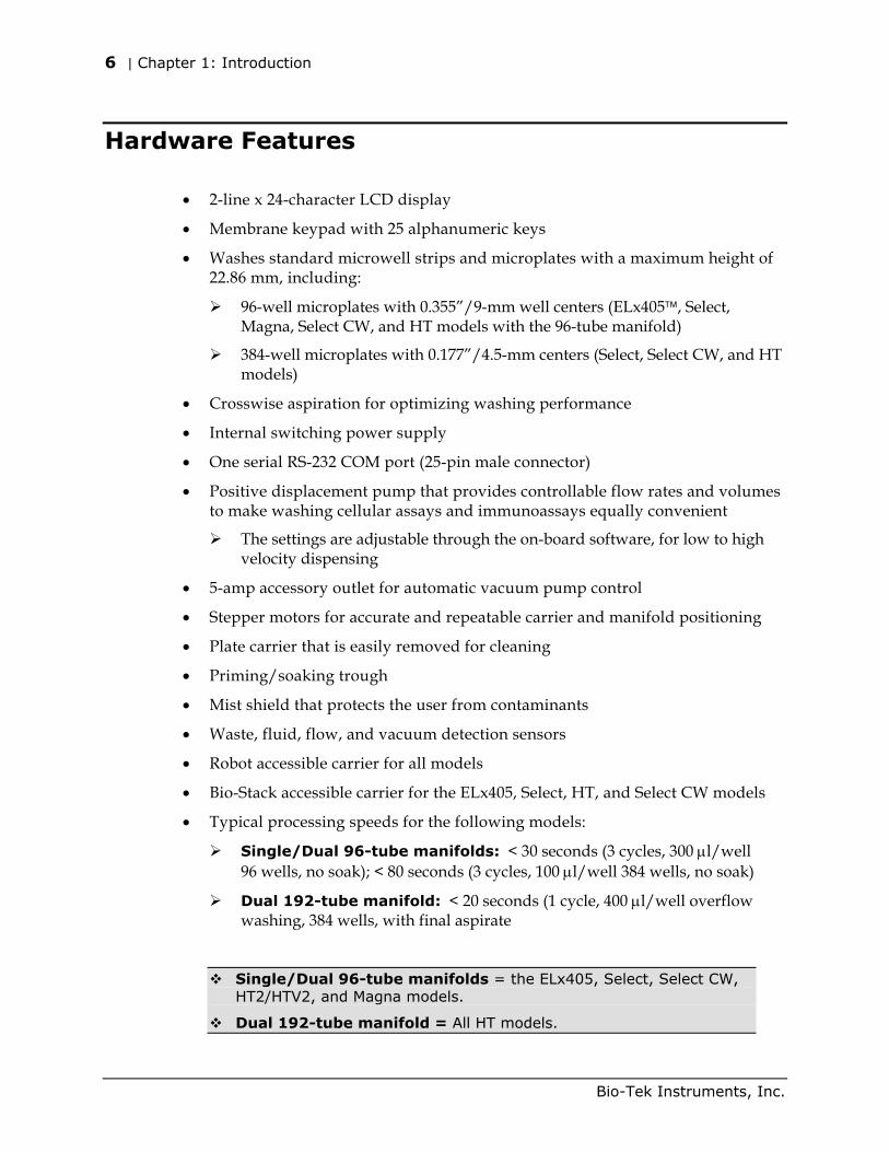
Hardware Features
• 2-line x 24-character LCD display
• Membrane keypad with 25 alphanumeric keys
• Washes standard microwell strips and microplates with a maximum height of 22.86 mm, including:
96-well microplates with 0.355”/9-mm well centers (ELx405, Select, Magna, Select CW, and HT models with the 96-tube manifold)
384-well microplates with 0.177”/4.5-mm centers (Select, Select CW, and HT models)
• Crosswise aspiration for optimizing washing performance
• Internal switching power supply
• One serial RS-232 COM port (25-pin male connector)
• Positive displacement pump that provides controllable flow rates and volumes to make washing cellular assays and immunoassays equally convenient
The settings are adjustable through the on-board software, for low to high velocity dispensing
• 5-amp accessory outlet for automatic vacuum pump control
• Stepper motors for accurate and repeatable carrier and manifold positioning
• Plate carrier that is easily removed for cleaning
• Priming/soaking trough
• Mist shield that protects the user from contaminants
• Waste, fluid, flow, and vacuum detection sensors
• Robot accessible carrier for all models
• Bio-Stack accessible carrier for the ELx405, Select, HT, and Select CW models
• Typical processing speeds for the following models:
Single/Dual 96-tube manifolds: < 30 seconds (3 cycles, 300 µl/well 96 wells, no soak); < 80 seconds (3 cycles, 100 µl/well 384 wells, no soak)
Dual 192-tube manifold: < 20 seconds (1 cycle, 400 µl/well overflow washing, 384 wells, with final aspirate
Single/Dual 96-tube manifolds = the ELx405, Select, Select CW, HT2/HTV2, and Magna models.
Dual 192-tube manifold = All HT models.
Bio-Tek Instruments, Inc.
Software Features | 7
Software Features
• Easy-to-use, menu-driven interface
• Ability to create Wash, Prime, Dispense, and Aspirate programs for automated microplate washing. Wash parameters such as number of cycles, wash volume, flow rate and soak time are individually programmed as part of a wash program and recalled when needed.
• Ability to link up to 10 programs
• Ability to create Soak programs for inclusion in a linked series of programs
• Quick repeat of previously run program
• User-definable washer program names, resulting in the rapid recall of desired wash protocols and plate dimension set-ups
• Programs may be copied, edited or deleted
• Program parameters may be locked. Requires custom program; contact Bio-Tek for more information
• Easy-to-update washer software
• Storage of up to 75 programs
• Preprogrammed maintenance programs
• Five shaking speeds for more intense washing
• Programmable aspiration height - ensures that the tubes do not touch the well bottom, allowing the handling of sensitive cell assays
• Support for the following languages: English, French, German, Italian, and Spanish.
Note: Contact Bio-Tek for information on changing to a different language.
ELx405 Operator's Guide
8 | Chapter 1: Introduction
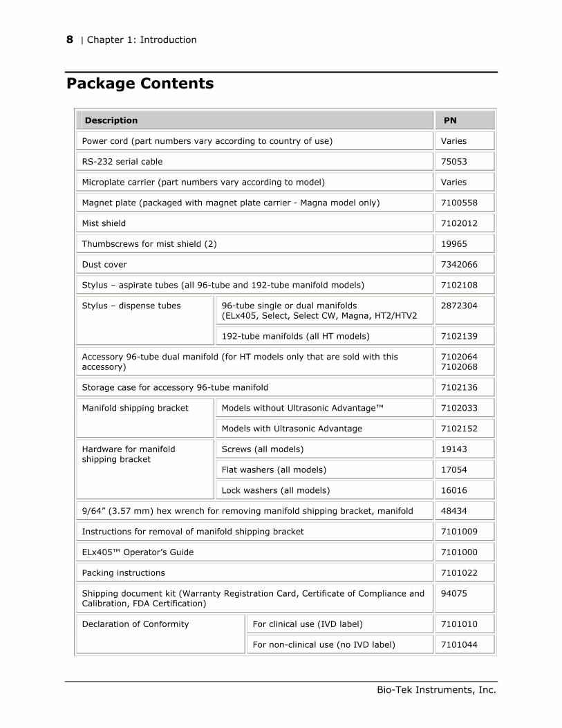
Package Contents
Description PN
Power cord (part numbers vary according to country of use) Varies
RS-232 serial cable 75053
Microplate carrier (part numbers vary according to model) Varies
Magnet plate (packaged with magnet plate carrier - Magna model only) 7100558
Mist shield 7102012
Thumbscrews for mist shield (2) 19965
Dust cover 7342066
Stylus – aspirate tubes (all 96-tube and 192-tube manifold models) 7102108
96-tube single or dual manifolds (ELx405, Select, Select CW, Magna, HT2/HTV2
2872304 Stylus – dispense tubes
192-tube manifolds (all HT models) 7102139
Accessory 96-tube dual manifold (for HT models only that are sold with this accessory)
7102064 7102068
Storage case for accessory 96-tube manifold 7102136
Models without Ultrasonic Advantage™ 7102033 Manifold shipping bracket
Models with Ultrasonic Advantage 7102152
Screws (all models) 19143
Flat washers (all models) 17054
Hardware for manifold shipping bracket
Lock washers (all models) 16016
9/64” (3.57 mm) hex wrench for removing manifold shipping bracket, manifold 48434
Instructions for removal of manifold shipping bracket 7101009
ELx405™ Operator’s Guide 7101000
Packing instructions 7101022
Shipping document kit (Warranty Registration Card, Certificate of Compliance and Calibration, FDA Certification)
94075
For clinical use (IVD label) 7101010 Declaration of Conformity
For non-clinical use (no IVD label) 7101044
Bio-Tek Instruments, Inc.
Optional Accessories | 9
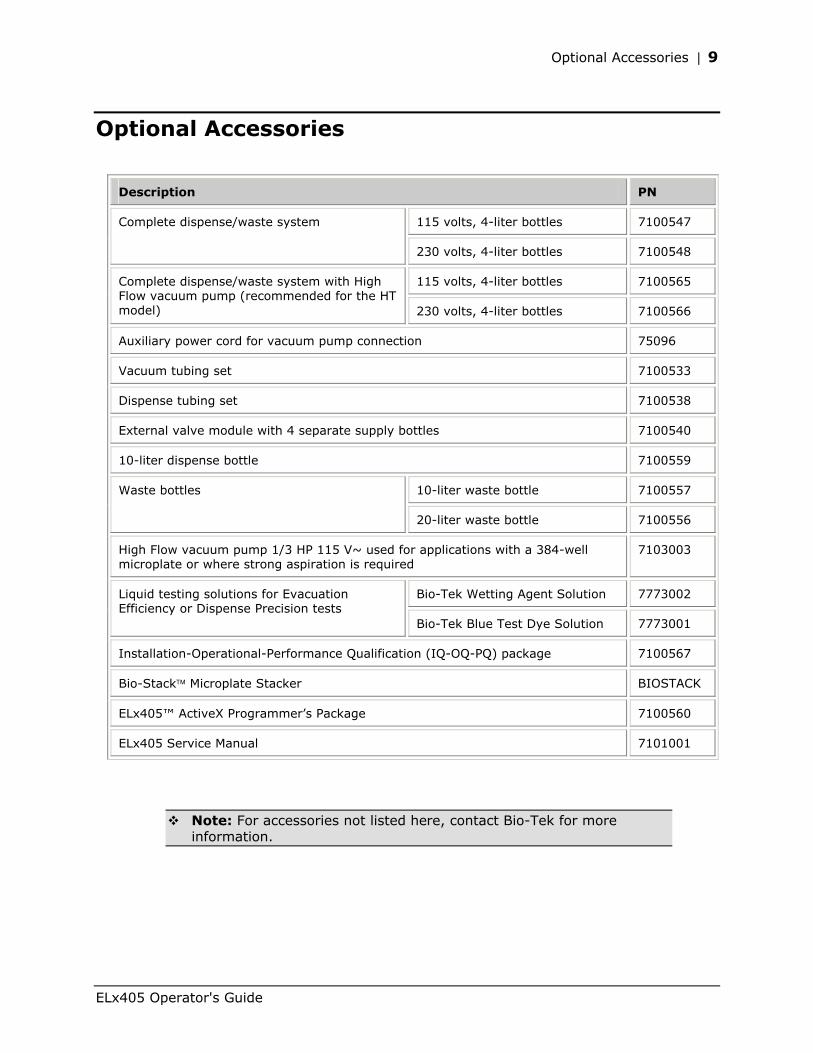
Optional Accessories
Description PN
115 volts, 4-liter bottles 7100547 Complete dispense/waste system
230 volts, 4-liter bottles 7100548
115 volts, 4-liter bottles 7100565 Complete dispense/waste system with High Flow vacuum pump (recommended for the HT model) 230 volts, 4-liter bottles 7100566
Auxiliary power cord for vacuum pump connection 75096
Vacuum tubing set 7100533
Dispense tubing set 7100538
External valve module with 4 separate supply bottles 7100540
10-liter dispense bottle 7100559
10-liter waste bottle 7100557 Waste bottles
20-liter waste bottle 7100556
High Flow vacuum pump 1/3 HP 115 V~ used for applications with a 384-well microplate or where strong aspiration is required
7103003
Bio-Tek Wetting Agent Solution 7773002 Liquid testing solutions for Evacuation Efficiency or Dispense Precision tests
Bio-Tek Blue Test Dye Solution 7773001
Installation-Operational-Performance Qualification (IQ-OQ-PQ) package 7100567
Bio-Stack Microplate Stacker BIOSTACK
ELx405™ ActiveX Programmer’s Package 7100560
ELx405 Service Manual 7101001
Note: For accessories not listed here, contact Bio-Tek for more information.
ELx405 Operator's Guide
10 | Chapter 1: Introduction
Specifications
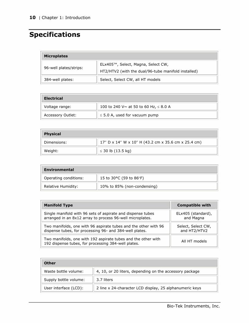
Microplates
96-well plates/strips: ELx405™, Select, Magna, Select CW,
HT2/HTV2 (with the dual/96-tube manifold installed)
384-well plates: Select, Select CW, all HT models
Electrical
Voltage range: 100 to 240 V~ at 50 to 60 Hz, ≤ 8.0 A
Accessory Outlet: ≤ 5.0 A, used for vacuum pump
Physical
Dimensions: 17” D x 14” W x 10” H (43.2 cm x 35.6 cm x 25.4 cm)
Weight: ≤ 30 lb (13.5 kg)
Environmental
Operating conditions: 15 to 30°C (59 to 86°F)
Relative Humidity: 10% to 85% (non-condensing)
Manifold Type Compatible with
Single manifold with 96 sets of aspirate and dispense tubes arranged in an 8x12 array to process 96-well microplates.
ELx405 (standard), and Magna
Two manifolds, one with 96 aspirate tubes and the other with 96 dispense tubes, for processing 96- and 384-well plates.
Select, Select CW, and HT2/HTV2
Two manifolds, one with 192 aspirate tubes and the other with 192 dispense tubes, for processing 384-well plates.
All HT models
Other
Waste bottle volume: 4, 10, or 20 liters, depending on the accessory package
Supply bottle volume: 3.7 liters
User interface (LCD): 2 line x 24-character LCD display, 25 alphanumeric keys
Bio-Tek Instruments, Inc.
Performance Specifications | 11
Performance Specifications
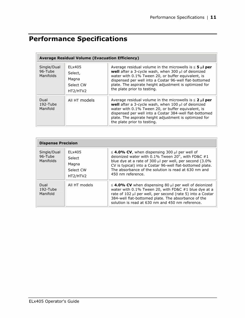
Average Residual Volume (Evacuation Efficiency)
Single/Dual 96-Tube Manifolds
ELx405
Select,
Magna
Select CW
HT2/HTV2
Average residual volume in the microwells is ≤ 5 µl per well after a 3-cycle wash, when 300 µl of deionized water with 0.1% Tween 20, or buffer equivalent, is dispensed per well into a Costar 96-well flat-bottomed plate. The aspirate height adjustment is optimized for the plate prior to testing.
Dual 192-Tube Manifold
All HT models Average residual volume in the microwells is ≤ 2 µl per well after a 3-cycle wash, when 100 µl of deionized water with 0.1% Tween 20, or buffer equivalent, is dispensed per well into a Costar 384-well flat-bottomed plate. The aspirate height adjustment is optimized for the plate prior to testing.
Dispense Precision
Single/Dual 96-Tube Manifolds
ELx405
Select
Magna
Select CW
HT2/HTV2
≤ 4.0% CV, when dispensing 300 µl per well of deionized water with 0.1% Tween 20, with FD&C #1 blue dye at a rate of 300 µl per well, per second (3.0% CV is typical) into a Costar 96-well flat-bottomed plate. The absorbance of the solution is read at 630 nm and 450 nm reference.
Dual 192-Tube Manifold
All HT models ≤ 4.0% CV when dispensing 80 µl per well of deionized water with 0.1% Tween 20, with FD&C #1 blue dye at a rate of 102 µl per well, per second (rate 5) into a Costar 384-well flat-bottomed plate. The absorbance of the solution is read at 630 nm and 450 nm reference.
ELx405 Operator's Guide
12 | Chapter 1: Introduction
Technical Support
Bio-Tek’s ELx405 Microplate Washer is backed by a superior support staff. The TAC engineers provide assistance with use and maintenance, troubleshooting support, and frequently asked questions.
The Bio-Tek Service Center provides periodic certification of laboratory instruments and calibration plates, performing both calibration and verification to ensure that your instrumentation meets the manufacturer’s specifications.
Our Service Center also provides repair and refurbishment services, thoroughly testing each repaired instrument to ensure it meets current factory performance specifications.
If the washer ever fails to work perfectly and you need troubleshooting assistance, or if you require certification, refurbishment, or repair of the instrument, please contact Bio-Tek’s Technical Assistance Center.
Whichever method of contact you choose, please be prepared to provide the following information:
• Product name and serial number
• The software configuration information. To see this information, start at the washer Main Menu and follow the path below:
UTIL TESTS CHKSUM
• For troubleshooting assistance or instruments needing repair:
the specific steps that produce your problem
any error codes displayed on the screen (descriptions of error codes are available in Appendix B, Error Codes)
• A daytime phone number
• Your name and company information
• A fax number and/or e-mail address, if available.
If you need to return the washer to Bio-Tek for service, contact Bio-Tek for a Return Materials Authorization (RMA) number. When obtaining the RMA, explain whether the washer requires calibration, cleaning, periodic maintenance, warranty work, and/or repair.
Repackage the washer properly (see Repackaging and Shipping in Chapter 2, Installation), and ship the instrument to Bio-Tek at the shipping address listed on the following page.
Note: Bio-Tek offers a Depot Service Contract for instruments after the initial warranty has expired, and field service contracts for several locations. Please refer to the Bio-Tek website for more information: www.biotek.com.
Bio-Tek Instruments, Inc.
Technical Support | 13
Phone Support
You can telephone the Technical Assistance Center between 8:30 AM and 5:30 PM Eastern Standard Time (EST), Monday through Friday, excluding holidays.
• Bio-Tek Instruments Main Number: 802-655-4040
• Technical Assistance Center: 800-242-4685
Electronic Communication
Electronic communication is available via the following:
• E-Mail: [email protected]
• Internet Site: www.biotek.com
Facsimile Support
You may send a fax with your questions or requests for help 24 hours a day to the following number:
• Technical Assistance Center: 802-655-3399
Written Communication
If you prefer, you may write a letter with your comments and send it to:
Bio-Tek Instruments, Inc. Technical Assistance Center P.O. Box 998, Highland Park Winooski, Vermont 05404-0998 USA
Shipping Address
Ship instruments that need repair or service to Bio-Tek at the following address:
Bio-Tek Instruments, Inc. Technical Assistance Center 100 Tigan Street Highland Park Winooski, Vermont 05404 USA
Please call or e-mail TAC for an RMA number before shipping the instrument.
ELx405 Operator's Guide
14 | Chapter 1: Introduction
Applications Support
Bio-Tek’s fully equipped Application Laboratory provides our on-staff scientists with the means to assist you with your most difficult applications. The primary focus of our scientists is to help you with the integration of our instrumentation and software with your unique scientific applications.
If you are having difficulty with washing cell-based assays, integrating a unique data reduction transformation, or just looking for a recommendation on an appropriate fluorophore, contact Bio-Tek at the phone numbers or e-mail address listed below.
Phone Support
You can telephone the Applications Support staff between 8:30 AM and 5:30 PM Eastern Standard Time (EST), Monday through Friday, excluding holidays.
• In the U.S. call: 888-451-5171
• Outside the U.S. call: 802-655-4740
Electronic Communication
Electronic communication is available via the following:
• E-Mail: [email protected]
• Internet Site: www.biotek.com
Bio-Tek Instruments, Inc.
Chapter 2
Installation
This chapter includes instructions for unpacking and setting up the ELx405 Microplate Washer, installing its components, and repackaging the instrument for shipment.
Unpacking and Inspecting the Instrument ..................................16 Removing the Manifold Shipping Bracket .....................................21 Setting Up the Washer..............................................................22 Verifying Performance ..............................................................35 Installation of the Washer for Operation with the Bio-Stack............36 Repackaging and Shipping ........................................................37
16 | Chapter 2: Installation
Unpacking and Inspecting the Instrument
Important! Save all packaging materials. If the ELx405 is shipped to the factory for repair or replacement, it must be carefully repackaged, according to the instructions in this chapter, using the original packing materials (PN 7103000). Using other forms of commercially available packing materials, or failing to follow the repackaging instructions may void your warranty. If the original packing materials have been damaged, replacements are available from Bio-Tek.
For customers who purchased the optional Valve Module (PN 7100540): The valve module should be returned with the ELx405 in order to ensure that the washer will meet published performance specifications when used with the valve module. Refer to the instructions in this chapter for unpacking the module and repackaging the unit for shipment. Use the original packaging materials for the valve module.
See Repackaging and Shipping at the end of this chapter for complete shipping instructions.
The ELx405 washer and its accessories are securely packaged inside custom-designed shipping materials. This packaging should protect the instrument from damage during shipping. Inspect the shipping box, packaging, instrument, and accessories for signs of damage.
If the washer is damaged: Notify the carrier and your manufacturer's representative. Keep the shipping cartons and packing material for the carrier's inspection. The manufacturer will arrange for repair or replacement of your instrument immediately, before the shipping-related claim is settled.
Refer to the unpacking instructions and Figures 2 through 7 on the following pages when removing the instrument, its accessories, and the external valve module from the shipping containers, and Figure 8 for removing the manifold shipping bracket.
See Repackaging and Shipping at the end of this chapter for complete shipping instructions.
To unpack the washer and its accessories:
1. Carefully open the top of the outer shipping box.
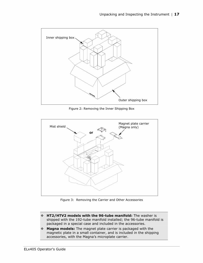
2. Lift out the inner shipping box that contains the washer and accessories (Figure 2) and place it on a level surface.
3. Open the top of the inner shipping box.
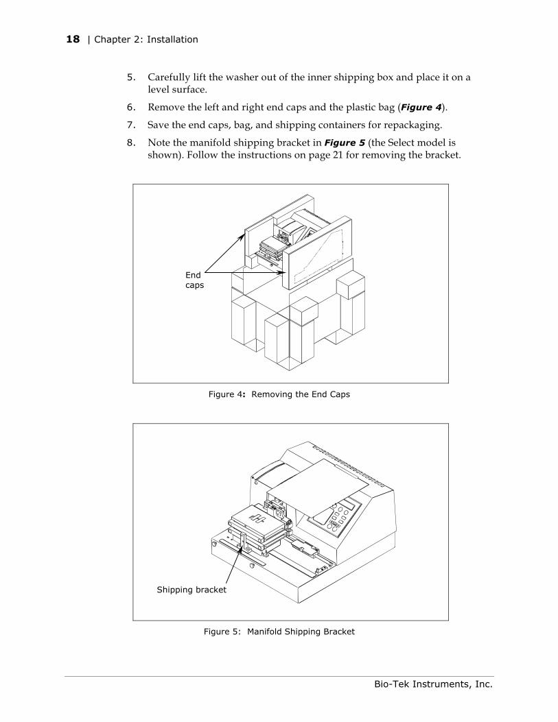
4. Remove the mist shield, model-specific carrier, shipping document kit, and other accessories (Figure 3) listed in Package Contents, Chapter 1.
Bio-Tek Instruments, Inc.
Unpacking and Inspecting the Instrument | 17
Inner shipping box
Outer shipping box
Figure 2: Removing the Inner Shipping Box
or
Magnet plate carrier (Magna only) Mist shield
Figure 3: Removing the Carrier and Other Accessories
HT2/HTV2 models with the 96-tube manifold: The washer is shipped with the 192-tube manifold installed; the 96-tube manifold is packaged in a special case and included in the accessories.
Magna models: The magnet plate carrier is packaged with the magnetic plate in a small container, and is included in the shipping accessories, with the Magna’s microplate carrier.
ELx405 Operator's Guide
18 | Chapter 2: Installation
5. Carefully lift the washer out of the inner shipping box and place it on a level surface.
6. Remove the left and right end caps and the plastic bag (Figure 4).
7. Save the end caps, bag, and shipping containers for repackaging.
8. Note the manifold shipping bracket in Figure 5 (the Select model is shown). Follow the instructions on page 21 for removing the bracket.
End caps
Figure 4: Removing the End Caps
Shipping bracket
Figure 5: Manifold Shipping Bracket
Bio-Tek Instruments, Inc.
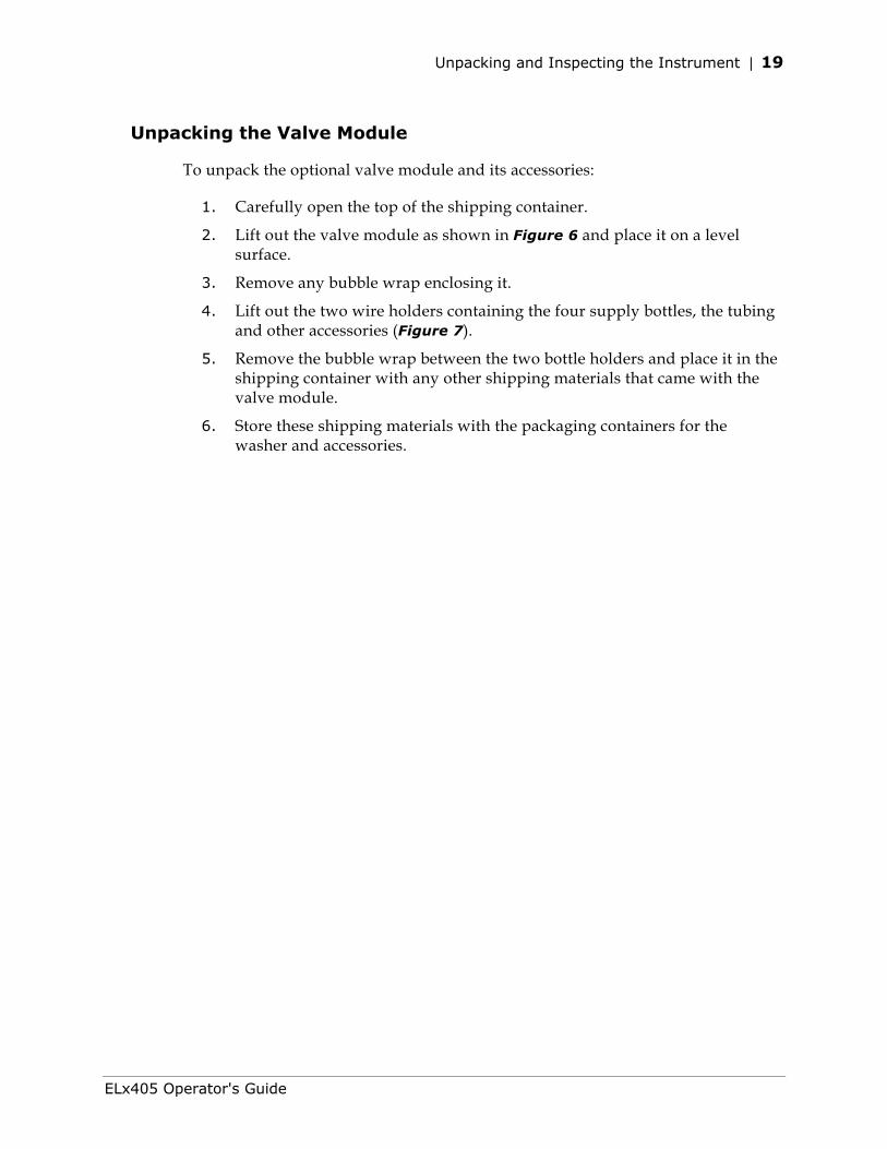
Unpacking and Inspecting the Instrument | 19
Unpacking the Valve Module
To unpack the optional valve module and its accessories:
1. Carefully open the top of the shipping container.
2. Lift out the valve module as shown in Figure 6 and place it on a level surface.
3. Remove any bubble wrap enclosing it.
4. Lift out the two wire holders containing the four supply bottles, the tubing and other accessories (Figure 7).
5. Remove the bubble wrap between the two bottle holders and place it in the shipping container with any other shipping materials that came with the valve module.
6. Store these shipping materials with the packaging containers for the washer and accessories.
ELx405 Operator's Guide
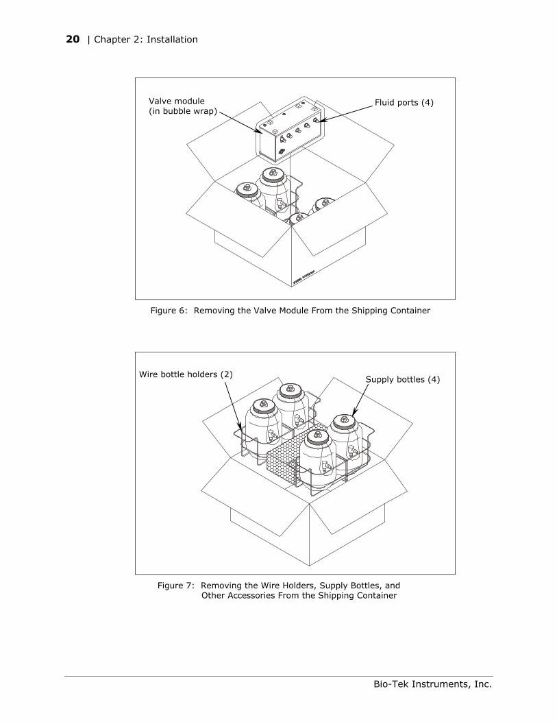
20 | Chapter 2: Installation
Valve module (in bubble wrap)
Fluid ports (4)
Figure 6: Removing the Valve Module From the Shipping Container
Wire bottle holders (2)
Supply bottles (4)
Figure 7: Removing the Wire Holders, Supply Bottles, and Other Accessories From the Shipping Container
Bio-Tek Instruments, Inc.
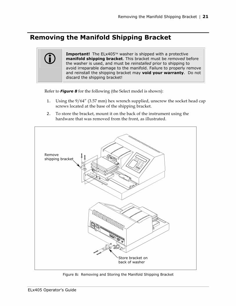
Removing the Manifold Shipping Bracket | 21
Removing the Manifold Shipping Bracket
Important! The ELx405 washer is shipped with a protective manifold shipping bracket. This bracket must be removed before the washer is used, and must be reinstalled prior to shipping to avoid irreparable damage to the manifold. Failure to properly remove and reinstall the shipping bracket may void your warranty. Do not discard the shipping bracket!
Refer to Figure 8 for the following (the Select model is shown):
1. Using the 9/64” (3.57 mm) hex wrench supplied, unscrew the socket head cap screws located at the base of the shipping bracket.
2. To store the bracket, mount it on the back of the instrument using the hardware that was removed from the front, as illustrated.
Remove shipping bracket
Store bracket on back of washer
Figure 8: Removing and Storing the Manifold Shipping Bracket
ELx405 Operator's Guide
22 | Chapter 2: Installation
Setting Up the Washer
Important! Avoid excessive humidity. Condensation directly on the sensitive electronic circuits can cause the instrument to fail internal self-checks.
Operating Environment
The washer is sensitive to extreme environmental conditions. For optimal operation, install the ELx405 Washer under the following conditions:
• On a level surface.
• In an area where ambient temperatures between 15°C and 30°C can be maintained.
• Away from excess humidity: 10% to 85% (non-condensing).
Installing the Microplate Carrier
Important! The microplate carrier has a serial number etched on the bottom side. This serial number should match the washer’s serial number. If the numbers do not match, call Bio-Tek immediately.
Refer to Figure 9 for the ELx405 model, Figure 10 for the Select, Select CW, and all HT models, and Figure 11 for the Magna model.
1. Line up the pin on the underside of the carrier with the slot on the carrier transport.
2. Snap the two carrier rail guides onto the transport rail. The pin should sit in the slot.
The Magna model comes with a magnet plate carrier that travels beneath the microplate carrier. Install the magnet plate carrier first: Line up the pin on the side of the carrier with the slot on the magnet plate carrier transport (lower) rail. Press down gently on the carrier to ensure that it is level with the washer’s base plate.
Bio-Tek Instruments, Inc.
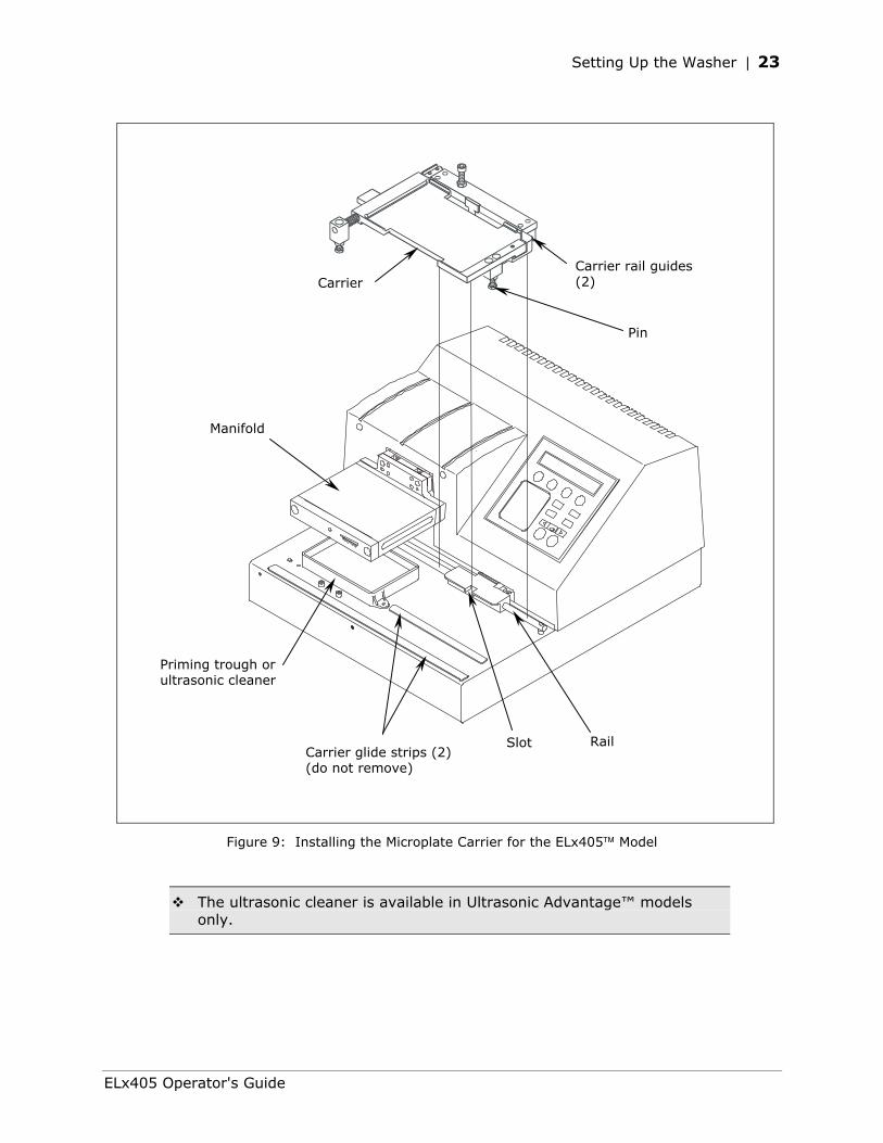
Setting Up the Washer | 23
Slot Rail
Priming trough or ultrasonic cleaner
Manifold
Carrier Carrier rail guides (2)
Pin
Carrier glide strips (2)(do not remove)
Figure 9: Installing the Microplate Carrier for the ELx405 Model
The ultrasonic cleaner is available in Ultrasonic Advantage™ models only.
ELx405 Operator's Guide
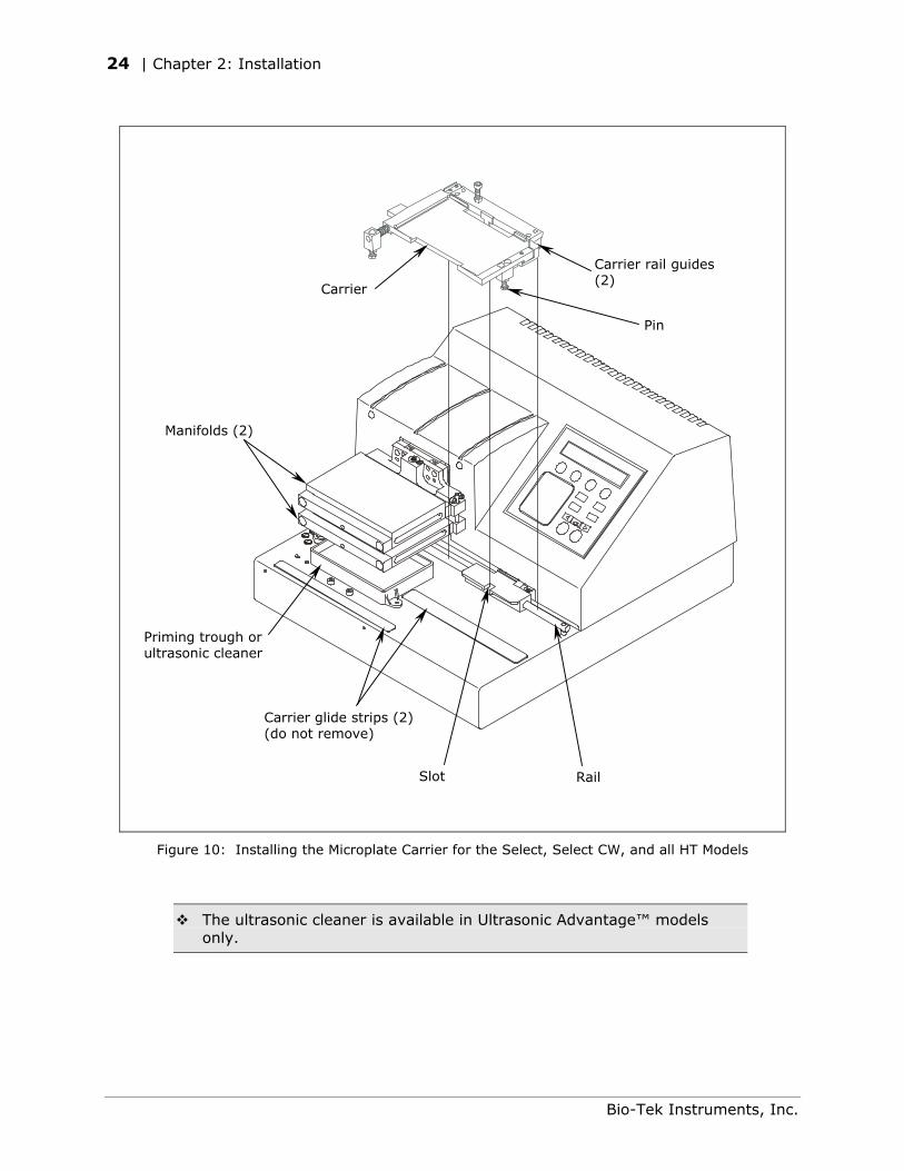
24 | Chapter 2: Installation
Carrier glide strips (2) (do not remove)
Priming trough or ultrasonic cleaner
Manifolds (2)
Pin
Carrier
Carrier rail guides(2)
Slot Rail
Figure 10: Installing the Microplate Carrier for the Select, Select CW, and all HT Models
The ultrasonic cleaner is available in Ultrasonic Advantage™ models only.
Bio-Tek Instruments, Inc.
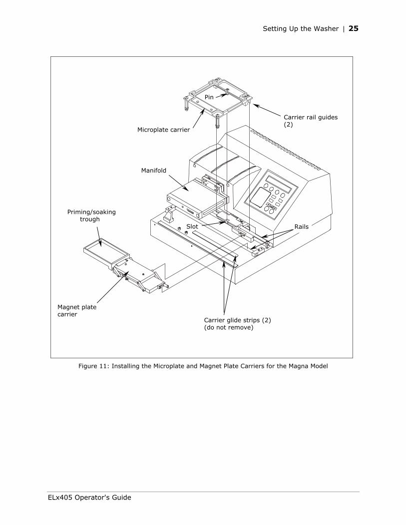
Setting Up the Washer | 25
Rails
Microplate carrier
Slot
Carrier rail guides (2)
Manifold
Pin
Priming/soaking trough
Magnet plate carrier
Carrier glide strips (2) (do not remove)
Figure 11: Installing the Microplate and Magnet Plate Carriers for the Magna Model
ELx405 Operator's Guide
26 | Chapter 2: Installation
Connecting the Tubes and Bottles
Important! If you are using the Bio-Stack Microplate Stacker with the ELx405, do not plug the external 24-VDC power supply that came with the Bio-Stack into the waste sensor port! See Figure 12 for the location of this port.
For optimal operation of the ELx405 washer, all tubing, cables, and fittings for the waste and supply systems must be properly connected.
Figure 12 on the following page illustrates the rear panel of instrument and the locations of the ports and connections for the waste and supply systems.
Before Connecting the Tubes and Bottles
Rinse all waste and supply bottles with deionized or distilled water before connecting them to the waste and supply tubing. This rinsing eliminates particles that may have collected during packing or unpacking.
Bio-Tek Instruments, Inc.
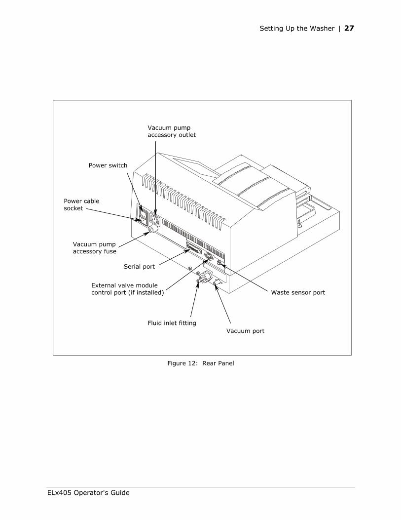
Setting Up the Washer | 27
Vacuum pump accessory outlet
Waste sensor port
Fluid inlet fitting
External valve module control port (if installed)
Serial port
Vacuum pump accessory fuse
Power switch
Power cable socket
Vacuum port
Figure 12: Rear Panel
ELx405 Operator's Guide
28 | Chapter 2: Installation
Waste System
Caution: High Flow Pump Installation. DO NOT plug the High Flow vacuum pump cable into a wall outlet! Use the adapter provided with the pump to connect the pump to the accessory outlet on the back of the washer. See Figure 12 for an illustration of the vacuum pump accessory outlet and Figure 13 for an illustration of the connection of the cable to the outlet. (See also the High Flow Pump Installation instructions, PN 7101049, included in the package contents of your ELx405 washer.)
There is no regulator on the pump; therefore, if the pump is plugged directly into a wall outlet, the pump will run continuously, resulting in vacuum levels outside the specified range. This requires the pump to draw a much higher current at setup in order to operate, and may blow the auxiliary 5-amp fuse (PN 46055) and/or produce arcing in the pump’s On/Off switch.
A Vacuum Dissipation Delay feature is available in the Setup utility that allows you to increase the delay, thereby preventing the pump from drawing excess current and blowing the 5-amp fuse. The delay should be set at 10 seconds or greater if using 10-liter bottles, and 20 seconds if using 20-liter bottles. Refer to Setup Utilities, Vacuum Dissipation Delay in Chapter 3, Operation.
Refer to Figures 12 and 13 for the following instructions.
1. Attach the single vacuum tube to the vacuum port on the back of the instrument and to the inlet port of the waste bottle.
2. Attach the waste sensor cable to the waste sensor port.
3. Important! Connect the vacuum pump to the vacuum pump accessory outlet on the back of the washer (see Caution above). Use the accessory outlet adapter provided.
4. Place the waste bottles and vacuum on the same surface as the washer to ensure optimum performance.
Note: To facilitate correct connection of the tubing to the waste bottles, the waste tubes have green or yellow labels that correspond to the green or yellow dots next to the inlet/outlet ports on the waste bottles.
Bio-Tek Instruments, Inc.
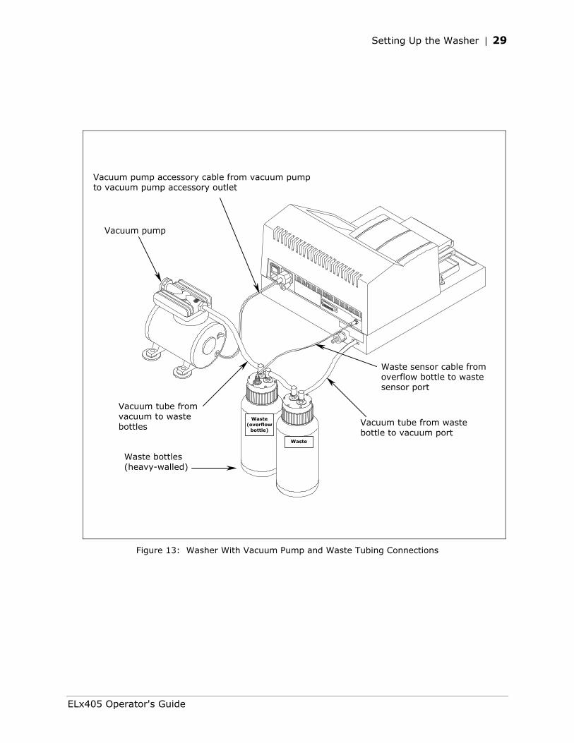
Setting Up the Washer | 29
Vacuum pump accessory cable from vacuum pump to vacuum pump accessory outlet
Vacuum pump
Waste sensor cable from overflow bottle to waste sensor port
Vacuum tube from waste bottle to vacuum port
Vacuum tube from vacuum to waste bottles
Waste (overflow
bottle)
Waste
Waste bottles (heavy-walled)
Figure 13: Washer With Vacuum Pump and Waste Tubing Connections
ELx405 Operator's Guide
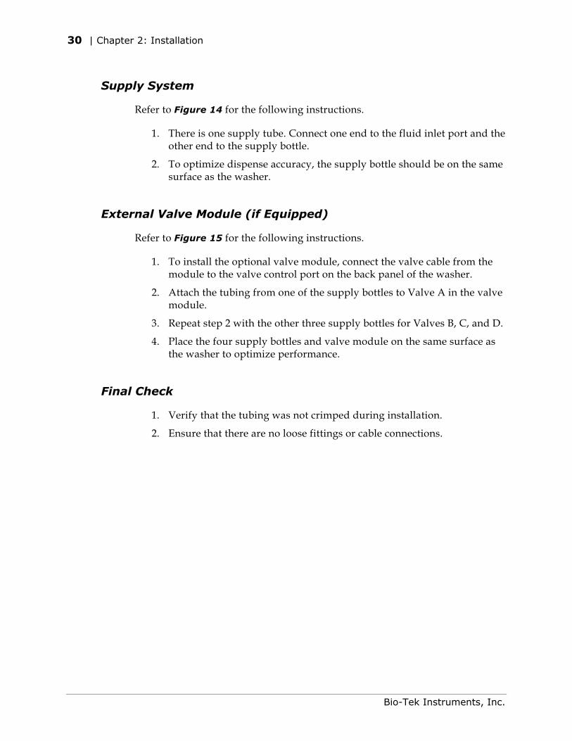
30 | Chapter 2: Installation
Supply System
Refer to Figure 14 for the following instructions.
1. There is one supply tube. Connect one end to the fluid inlet port and the other end to the supply bottle.
2. To optimize dispense accuracy, the supply bottle should be on the same surface as the washer.
External Valve Module (if Equipped)
Refer to Figure 15 for the following instructions.
1. To install the optional valve module, connect the valve cable from the module to the valve control port on the back panel of the washer.
2. Attach the tubing from one of the supply bottles to Valve A in the valve module.
3. Repeat step 2 with the other three supply bottles for Valves B, C, and D.
4. Place the four supply bottles and valve module on the same surface as the washer to optimize performance.
Final Check
1. Verify that the tubing was not crimped during installation.
2. Ensure that there are no loose fittings or cable connections.
Bio-Tek Instruments, Inc.
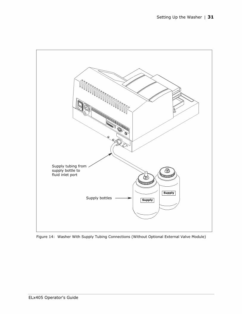
Setting Up the Washer | 31
Supply bottles
Supply tubing from supply bottle to fluid inlet port
Supply
Supply
Figure 14: Washer With Supply Tubing Connections (Without Optional External Valve Module)
ELx405 Operator's Guide
32 | Chapter 2: Installation
Supply tube connected from valve module to fluidinlet fitting
Supply bottles (thin-walled)
D
C
B
A
Supply
Valve cable connectedfrom valve module to valve control port
Valve module
Figure 15: Washer With Optional External Valve Module
Bio-Tek Instruments, Inc.
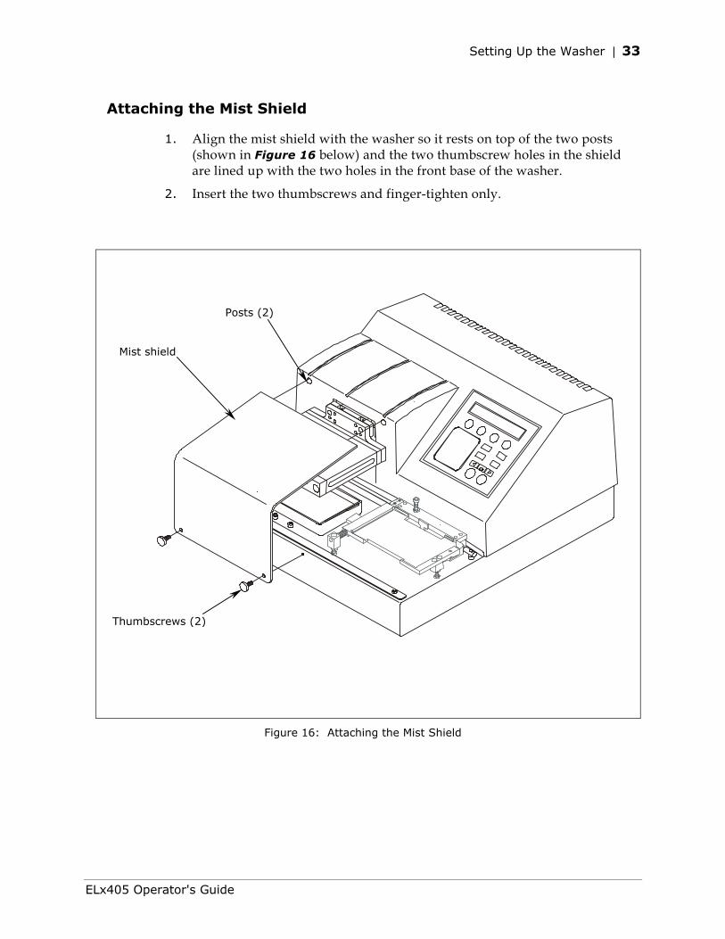
Setting Up the Washer | 33
Attaching the Mist Shield
1. Align the mist shield with the washer so it rests on top of the two posts (shown in Figure 16 below) and the two thumbscrew holes in the shield are lined up with the two holes in the front base of the washer.
2. Insert the two thumbscrews and finger-tighten only.
Thumbscrews (2)
Mist shield
Posts (2)
Figure 16: Attaching the Mist Shield
ELx405 Operator's Guide
34 | Chapter 2: Installation
Connecting the Power Cord
Warning! Power Rating. The ELx405 must be connected to a power receptacle that provides voltage and current within the specified rating for the system. Use of an incompatible power receptacle may produce electrical shock and fire hazards.
Warning! Electrical Grounding. Never use a two-prong plug adapter to connect primary power to the ELx405. Use of a two-prong adapter disconnects the utility ground, creating a severe shock hazard. Always connect the system power cord directly to a three-prong receptacle with a functional ground.
The ELx405 has a built-in switching power supply that automatically adjusts for input voltage in the range of 100-240 V~ at 50-60 Hz.
1. Insert the power cable into the power cable socket in the rear panel of the washer.
2. Insert the three-prong plug into an appropriate three-prong receptacle that has a functional ground.
Serial Port for Communication With Other Devices
The ELx405 has a 25-pin serial (RS-232) port located on the rear panel of the instrument (see Figure 12). The serial port allows the washer to receive data from a computer for purposes of factory or dealer service.
Bio-Tek Instruments, Inc.
Verifying Performance | 35
Verifying Performance
Before using the ELx405 Washer for the first time, verify that it is operating properly by turning the washer on. The washer will automatically perform a System Self Test to check the manifold, and manifold-to-carrier positioning. It also performs a magnetic carrier load test on the Magna models.
You can also choose to run this test from the washer's front panel. To run the washer’s System Self Test, follow the washer menu path shown below.
UTIL TESTS SLFCHK
If the test passes, the Main Menu will be displayed.
If the test fails, the washer will beep repeatedly and the display will show an error code. If this happens, note the error code and then press the Stop key on the keypad to stop the beeping. Refer to Appendix B, Error Codes, to determine its cause. If the problem is something you can fix, turn off the washer, fix the problem, and then turn the washer back on. If the cause is not something you can fix, contact Bio-Tek’s Technical Assistance Center.
Chapter 5, Performance Verification/Qualification Tests provides recommended Installation and Operational Qualification procedures to be performed after the instrument is installed and set up as described in this chapter, and before the instrument is used in a laboratory environment.
The successful completion of the Installation Qualification confirms that the washer and its components have been supplied as ordered and ensures that they are assembled and configured properly for your lab environment.
The successful completion of the Operational Qualification confirms that the washer is operating according to specification.
Note: An instrument qualification package (PN 7100567) for the ELx405 is available for purchase from Bio-Tek. The package contains thorough procedures for performing Installation Qualification, Operational Qualification and Performance Qualification (IQ-OQ-PQ) and preventive maintenance (PM). Extensive Checklists and Logbooks are included for recording results. Contact your local dealer for more information.
Important! Before operating this washer, review the General Usage Guidelines in Chapter 3, Operation. These guidelines include necessary steps to perform before running any program, information on performing periodic maintenance, and points to consider when creating or editing washer programs.
ELx405 Operator's Guide
36 | Chapter 2: Installation
Installation of the Washer for Operation with the Bio-Stack
Installation of the ELx405 for operation with the Bio-Stack Microplate Stacker includes the following:
• Installation of special alignment hardware on both instruments.
• Serial cable connection between the Bio-Stack and the PC controlling the Stacker.
An accessory package (PN 7310010) that contains the alignment hardware for both instruments and a serial cable is included with the Bio-Stack.
Please refer to your Bio-Stack Operator’s Manual for complete installation instructions.
Some ELx405 instruments may need to be upgraded for Bio-Stack compatibility. Refer to Upgrade Information in Chapter 1 of the Bio-Stack Operator’s Manual, or contact Bio-Tek for more information.
Bio-Tek Instruments, Inc.
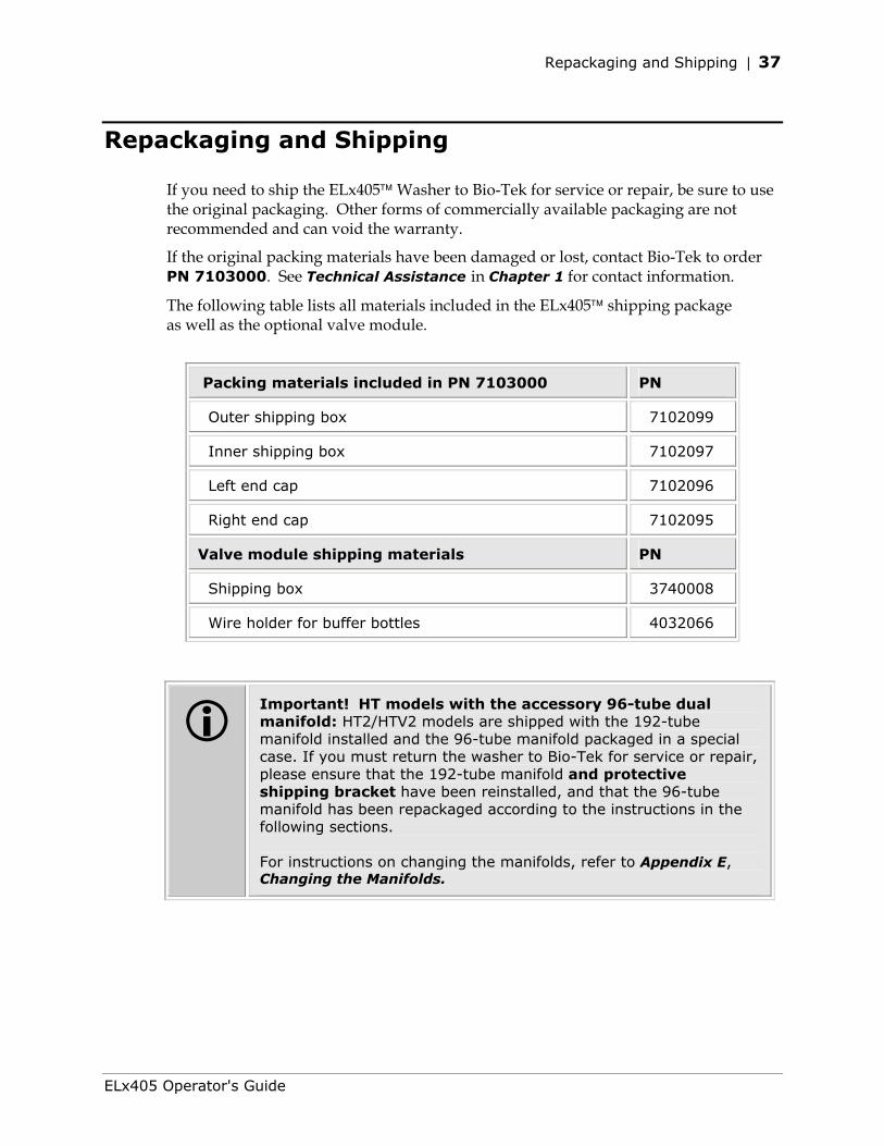
Repackaging and Shipping | 37
Repackaging and Shipping
If you need to ship the ELx405 Washer to Bio-Tek for service or repair, be sure to use the original packaging. Other forms of commercially available packaging are not recommended and can void the warranty.
If the original packing materials have been damaged or lost, contact Bio-Tek to order PN 7103000. See Technical Assistance in Chapter 1 for contact information.
The following table lists all materials included in the ELx405 shipping package as well as the optional valve module.
Packing materials included in PN 7103000 PN
Outer shipping box 7102099
Inner shipping box 7102097
Left end cap 7102096
Right end cap 7102095
Valve module shipping materials PN
Shipping box 3740008
Wire holder for buffer bottles 4032066
Important! HT models with the accessory 96-tube dual manifold: HT2/HTV2 models are shipped with the 192-tube manifold installed and the 96-tube manifold packaged in a special case. If you must return the washer to Bio-Tek for service or repair, please ensure that the 192-tube manifold and protective shipping bracket have been reinstalled, and that the 96-tube manifold has been repackaged according to the instructions in the following sections. For instructions on changing the manifolds, refer to Appendix E, Changing the Manifolds.
ELx405 Operator's Guide
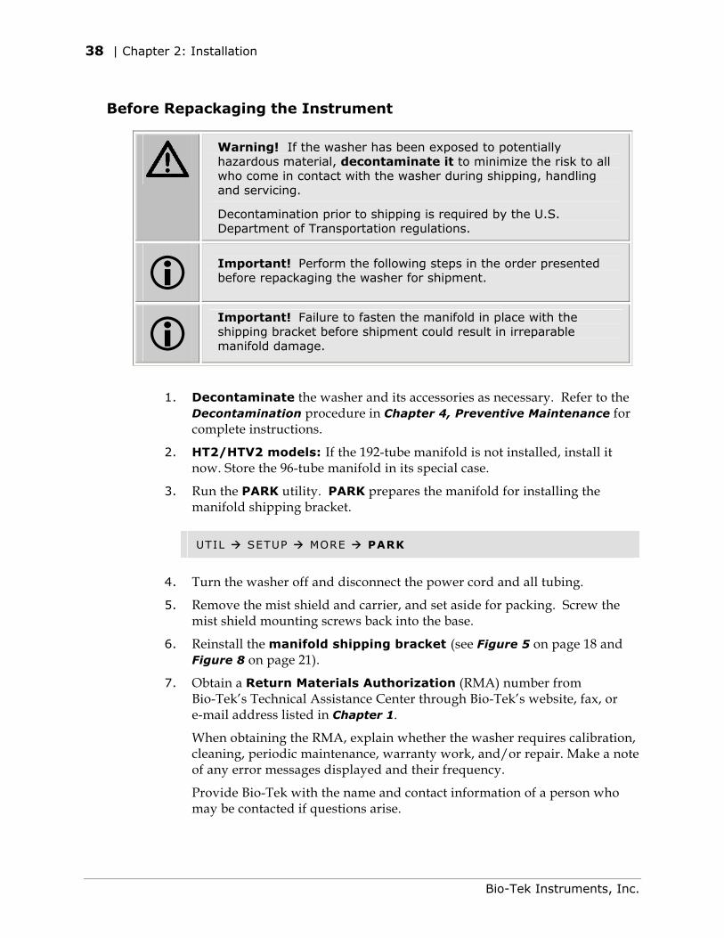
38 | Chapter 2: Installation
Before Repackaging the Instrument
Warning! If the washer has been exposed to potentially hazardous material, decontaminate it to minimize the risk to all who come in contact with the washer during shipping, handling and servicing.
Decontamination prior to shipping is required by the U.S. Department of Transportation regulations.
Important! Perform the following steps in the order presented before repackaging the washer for shipment.
Important! Failure to fasten the manifold in place with the shipping bracket before shipment could result in irreparable manifold damage.
1. Decontaminate the washer and its accessories as necessary. Refer to the Decontamination procedure in Chapter 4, Preventive Maintenance for complete instructions.
2. HT2/HTV2 models: If the 192-tube manifold is not installed, install it now. Store the 96-tube manifold in its special case.
3. Run the PARK utility. PARK prepares the manifold for installing the manifold shipping bracket.
UTIL SETUP MORE PARK
4. Turn the washer off and disconnect the power cord and all tubing.
5. Remove the mist shield and carrier, and set aside for packing. Screw the mist shield mounting screws back into the base.
6. Reinstall the manifold shipping bracket (see Figure 5 on page 18 and Figure 8 on page 21).
7. Obtain a Return Materials Authorization (RMA) number from Bio-Tek’s Technical Assistance Center through Bio-Tek’s website, fax, or e-mail address listed in Chapter 1.
When obtaining the RMA, explain whether the washer requires calibration, cleaning, periodic maintenance, warranty work, and/or repair. Make a note of any error messages displayed and their frequency.
Provide Bio-Tek with the name and contact information of a person who may be contacted if questions arise.
Bio-Tek Instruments, Inc.
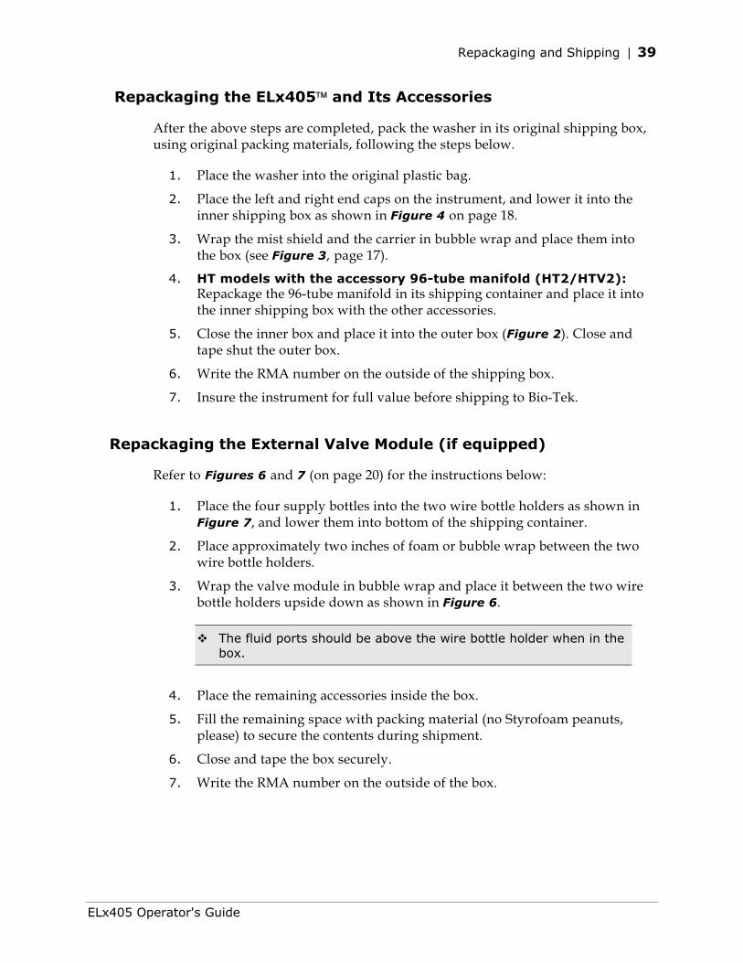
Repackaging and Shipping | 39
Repackaging the ELx405 and Its Accessories
After the above steps are completed, pack the washer in its original shipping box, using original packing materials, following the steps below.
1. Place the washer into the original plastic bag.
2. Place the left and right end caps on the instrument, and lower it into the inner shipping box as shown in Figure 4 on page 18.
3. Wrap the mist shield and the carrier in bubble wrap and place them into the box (see Figure 3, page 17).
4. HT models with the accessory 96-tube manifold (HT2/HTV2): Repackage the 96-tube manifold in its shipping container and place it into the inner shipping box with the other accessories.
5. Close the inner box and place it into the outer box (Figure 2). Close and tape shut the outer box.
6. Write the RMA number on the outside of the shipping box.
7. Insure the instrument for full value before shipping to Bio-Tek.
Repackaging the External Valve Module (if equipped)
Refer to Figures 6 and 7 (on page 20) for the instructions below:
1. Place the four supply bottles into the two wire bottle holders as shown in Figure 7, and lower them into bottom of the shipping container.
2. Place approximately two inches of foam or bubble wrap between the two wire bottle holders.
3. Wrap the valve module in bubble wrap and place it between the two wire bottle holders upside down as shown in Figure 6.
The fluid ports should be above the wire bottle holder when in the box.
4. Place the remaining accessories inside the box.
5. Fill the remaining space with packing material (no Styrofoam peanuts, please) to secure the contents during shipment.
6. Close and tape the box securely.
7. Write the RMA number on the outside of the box.
ELx405 Operator's Guide

40 | Chapter 2: Installation
Bio-Tek Instruments, Inc.
Chapter 3
Operation
This chapter includes instructions for operating the ELx405 Microplate Washer and its software.
ELx405 Front Panel ..................................................................42 Keypad Description ..................................................................43 Entering Program Names ..........................................................44 System Startup .......................................................................45 Main Menu..............................................................................46 Programs................................................................................47 Operation With the Bio-Stack ....................................................48 General Usage Guidelines .........................................................49 Wash .....................................................................................52 Prime.....................................................................................73 Dispense ................................................................................79 Aspiration...............................................................................83 Soak......................................................................................86 Linking Programs.....................................................................88 Setup Utilities .........................................................................91 ELx405 Washer Menu Maps.......................................................96
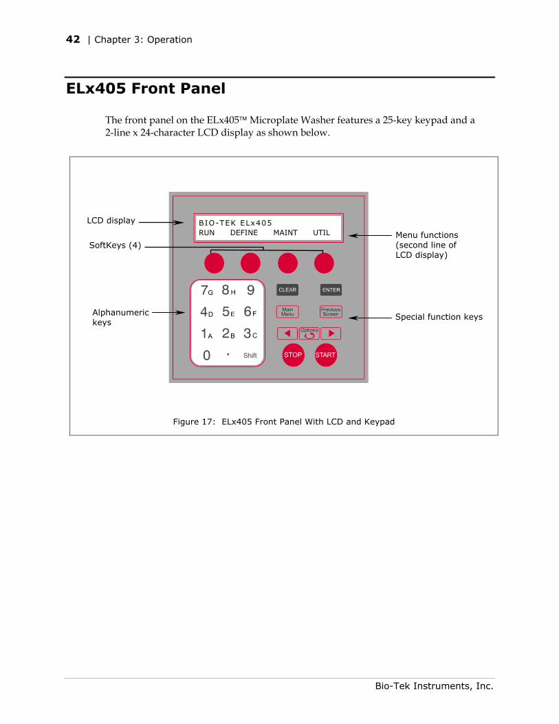
42 | Chapter 3: Operation
ELx405 Front Panel
The front panel on the ELx405 Microplate Washer features a 25-key keypad and a 2-line x 24-character LCD display as shown below.
Figure 17: ELx405 Front Panel With LCD and Keypad
Alphanumeric keys
Special function keys
Menu functions (second line of LCD display)
SoftKeys (4)
LCD display BIO-TEK ELx405 RUN DEFINE MAINT UTIL
Bio-Tek Instruments, Inc.
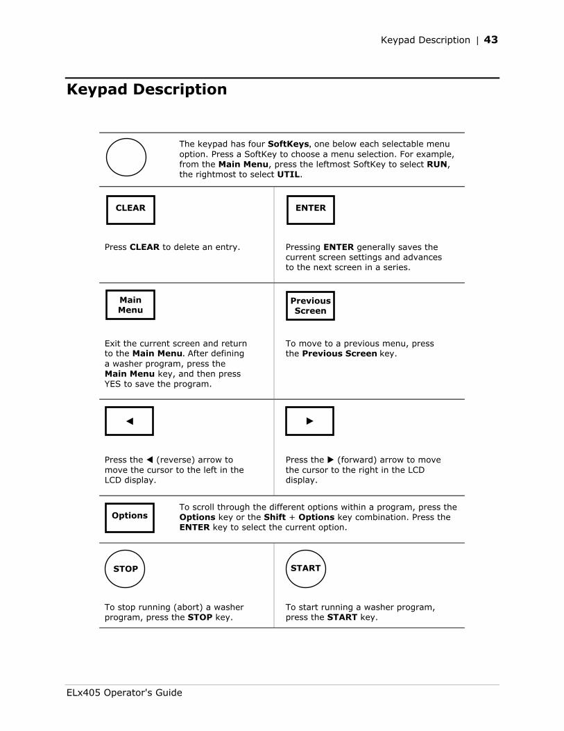
Keypad Description | 43
Keypad Description
The keypad has four SoftKeys, one below each selectable menu
option. Press a SoftKey to choose a menu selection. For example, from the Main Menu, press the leftmost SoftKey to select RUN, the rightmost to select UTIL.
Press CLEAR to delete an entry. Pressing ENTER generally saves the current screen settings and advances to the next screen in a series.
Exit the current screen and return to the Main Menu. After defining a washer program, press the Main Menu key, and then press YES to save the program.
To move to a previous menu, press the Previous Screen key.
Press the (reverse) arrow to move the cursor to the left in the LCD display.
Press the (forward) arrow to move the cursor to the right in the LCD display.
To scroll through the different options within a program, press the Options key or the Shift + Options key combination. Press the ENTER key to select the current option.
To stop running (abort) a washer program, press the STOP key.
To start running a washer program, press the START key.
CLEAR ENTER
Main Menu
Previous Screen
Options
START STOP
ELx405 Operator's Guide
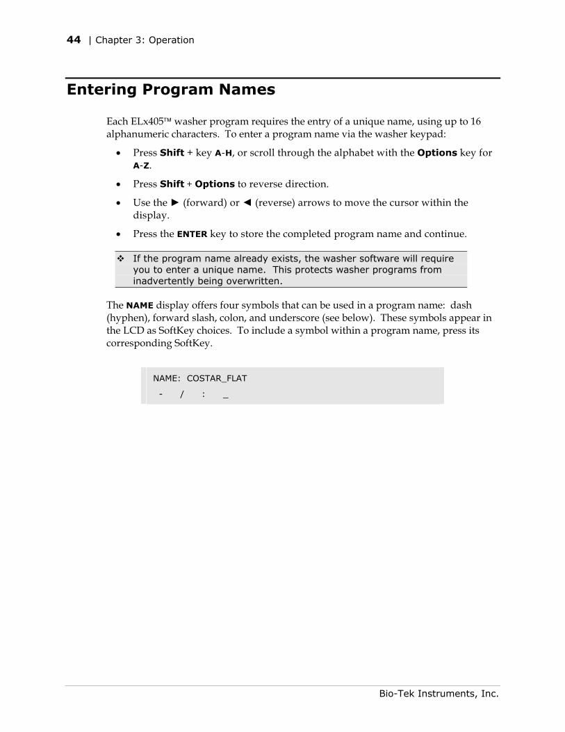
44 | Chapter 3: Operation
Entering Program Names
Each ELx405 washer program requires the entry of a unique name, using up to 16 alphanumeric characters. To enter a program name via the washer keypad:
• Press Shift + key A-H, or scroll through the alphabet with the Options key for A-Z.
• Press Shift + Options to reverse direction.
• Use the ► (forward) or ◄ (reverse) arrows to move the cursor within the display.
• Press the ENTER key to store the completed program name and continue.
If the program name already exists, the washer software will require you to enter a unique name. This protects washer programs from inadvertently being overwritten.
The NAME display offers four symbols that can be used in a program name: dash (hyphen), forward slash, colon, and underscore (see below). These symbols appear in the LCD as SoftKey choices. To include a symbol within a program name, press its corresponding SoftKey.
NAME: COSTAR_FLAT
- / : _
Bio-Tek Instruments, Inc.
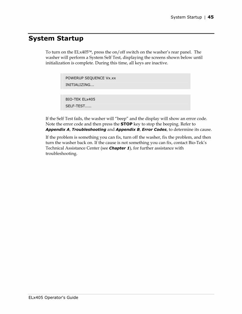
System Startup | 45
System Startup
To turn on the ELx405, press the on/off switch on the washer’s rear panel. The washer will perform a System Self Test, displaying the screens shown below until initialization is complete. During this time, all keys are inactive.
POWERUP SEQUENCE Vx.xx
INITIALIZING...
BIO-TEK ELx405
SELF-TEST.....
If the Self Test fails, the washer will “beep” and the display will show an error code. Note the error code and then press the STOP key to stop the beeping. Refer to Appendix A, Troubleshooting and Appendix B, Error Codes, to determine its cause.
If the problem is something you can fix, turn off the washer, fix the problem, and then turn the washer back on. If the cause is not something you can fix, contact Bio-Tek’s Technical Assistance Center (see Chapter 1), for further assistance with troubleshooting.
ELx405 Operator's Guide
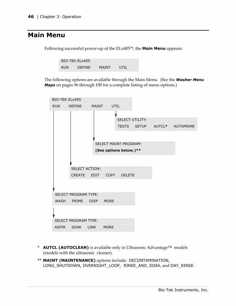
46 | Chapter 3: Operation
Main Menu
Following successful power-up of the ELx405, the Main Menu appears:
BIO-TEK ELx405
RUN DEFINE MAINT UTIL
The following options are available through the Main Menu. (See the Washer Menu Maps on pages 96 through 100 for a complete listing of menu options.)
* AU(m
** MALO
BIO-TEK ELx405
RUN DEFINE MAINT UTIL
SELECT ACTION:
CREATE EDIT COPY DELETE
To
IN
SELECT PROGRAM TYPE:
WASH PRIME DISP MORE
SELECT PROGRAM TYPE:
ASPIR SOAK LINK MORE
CL (AUTOCLEAN) idels with the ultrason
NT (MAINTENANCG_SHUTDOWN, OVE
SELECT MAINT PROGRAM: (See options below.)**
s available oic cleaner).
E) options iRNIGHT_LO
SELECT UTILITY:
TESTS SETUP AUTCL* AUTOPRIME
nly in Ultrasonic Advantage™ models
nclude: DECONTAMINATION, OP, RINSE_AND_SOAK, and DAY_RINSE.
Bio-Tek Instruments, Inc.
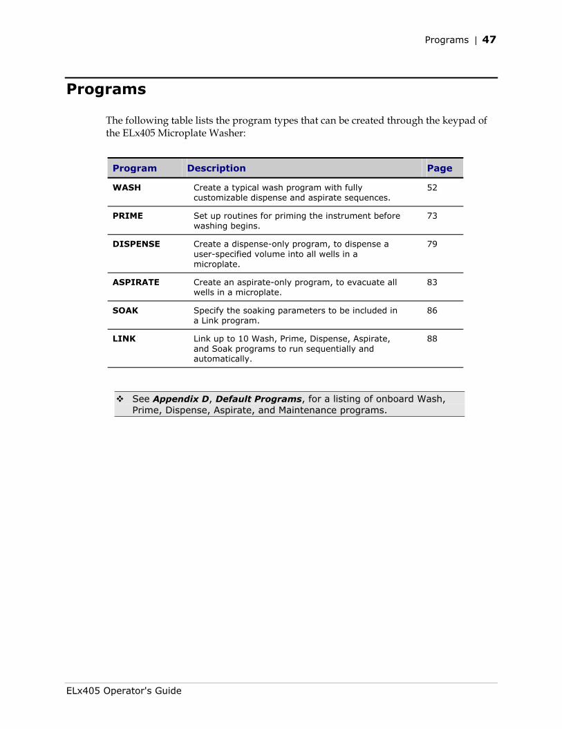
Programs | 47
Programs
The following table lists the program types that can be created through the keypad of the ELx405 Microplate Washer:
Program Description Page
WASH Create a typical wash program with fully customizable dispense and aspirate sequences.
52
PRIME Set up routines for priming the instrument before washing begins.
73
DISPENSE Create a dispense-only program, to dispense a user-specified volume into all wells in a microplate.
79
ASPIRATE Create an aspirate-only program, to evacuate all wells in a microplate.
83
SOAK Specify the soaking parameters to be included in a Link program.
86
LINK Link up to 10 Wash, Prime, Dispense, Aspirate, and Soak programs to run sequentially and automatically.
88
See Appendix D, Default Programs, for a listing of onboard Wash, Prime, Dispense, Aspirate, and Maintenance programs.
ELx405 Operator's Guide
48 | Chapter 3: Operation
Operation With the Bio-Stack
If you have purchased the Bio-Stack Microplate Stacker to operate with the washer, refer to the instructions in your Bio-Stack Operator’s Manual for setting up and configuring the washer to operate with the Bio-Stack.
You can run Wash, Dispense, Aspirate and Link programs whether the washer is operated with or without the Bio-Stack. The Prime, Soak, and Maintenance programs are run on the washer without the Bio-Stack.
The Magna model does not support the Bio-Stack.
Bio-Tek Instruments, Inc.
General Usage Guidelines | 49
General Usage Guidelines
When operating the washer, follow these guidelines to ensure optimal performance in the washer and to prevent the problems described in the troubleshooting charts in Appendix A, Troubleshooting.
Important! HT models with the 96-tube manifold: The washer software must be configured for operation with the manifold installed (96 or 192). Refer to Manifold Selection (MANIFOLD), on page 95, for instructions. Failure to set the manifold type before operating the washer will result in poor performance of the instrument, and may damage the manifold, and void your warranty.
Before Running Any Program
• Fill the wash/rinse bottles with sufficient fluid. Make sure the supply tube is in the liquid.
• The supply tube should extend to the bottom of the bottle and be cut at the end (see drawing to the right) to ensure free flow of liquid at the bottom of the supply bottle.
• Empty the waste bottles and firmly seat the waste bottles’ stoppers. To ensure that fluid does not back up into the vacuum pump during operation, always operate the washer with the waste sensor cable installed and the waste detection sensor activated (refer to Sensor System, page 91). If fluid collects in the overflow bottle, thoroughly rinse the level switch assembly and bottle.
• Check the external tubing connections for kinks and clogs.
• Make sure the bottles, solutions, and tubing are clean and do not contain any particles or mold. Water and dye solutions that are recycled over several days will grow algae, bacteria, molds, or other undesirable organisms.
• If there are large air pockets in the tubing, run a Prime program before running another program. Use the volumes specified for the following models (see Recommended Prime and Low Flow Prime Volumes, page 76):
ELx405, Magna, Select, and HT models. Without the external valve module: 200 ml Prime Volume, when all the lines are empty or when changing fluids. With the valve module: 400 ml Prime Volume, when all the lines are empty or when changing fluids.
Select CW model. Without the valve module: 200 ml Prime Volume and 150 ml Low Flow Prime Volume, when all the lines are empty; 300 ml Prime Volume and 200 ml Low Flow Prime Volume, when changing fluids. With the valve module: 400 ml Prime Volume and 300 ml Low Flow Prime Volume, when all the lines are empty; 600 ml Prime Volume and 400 ml Low Flow Prime Volume, when changing fluids.
ELx405 Operator's Guide
50 | Chapter 3: Operation
• To avoid creating air bubbles every time the wash or rinse bottle is filled, make a mark halfway down the bottle and refill when the fluid level has dropped to that point. Unscrew the cap and let it hang over the side just enough to avoid emptying the inside tube and enough to refill the bottle.
• When placing a microplate on the carrier, make sure that well A1 is in the left rear corner as you face the front of the washer, and that the plate is firmly seated in the carrier. The microplate spring holds the microplate against the front edge of the carrier.
Maintenance
Rinse and soak the fluid path, clean and replace components, and decontaminate the washer as described in Chapter 4, Preventive Maintenance. The following components should be periodically cleaned:
• Bottles
• Plate carrier system
• Manifold
• Aspirate/dispense tubes
• Mist shield
• Inlet filter
Models with the Ultrasonic Advantage™ (ultrasonic cleaner): An AUTOCLEAN program should be run on a periodic basis.
The following components should be periodically replaced:
• O-rings and channel-end seals
Frequent inspection of the washer, tubing, and bottles for possible causes listed below may help to eliminate many of the problems listed in Appendix A, Troubleshooting.
• Loose or incorrect connections of power cord, vacuum pump accessory cable, external valve module cable, supply/waste tubing, or fittings
• Incomplete or incorrect installation of manifold or carrier, attachment of mist shield, or placement of microplate/microstrips in carrier
• Accumulation of residue on carrier or inside aspirate/dispense tubes, waste/supply bottles or tubing, manifold, inlet/outlet fittings
• Worn tubing, o-rings or channel-end seals
• Kinked or bent aspirate/dispense tubes or waste/supply tubing
Bio-Tek Instruments, Inc.
General Usage Guidelines | 51
Programming Considerations
• Dispense Height: The dispense (overflow) height in the wash protocol should be low enough to ensure that excess fluid is removed by the aspirate tubes when the manifold is dispensing.
• Plate Clearance: Ensure that a sufficient plate clearance height is programmed for plates that are slightly taller than standard plates. See Plate Clearance Height (PLATE), p. 94.
• Vacuum Dissipation Delay: Increase the vacuum dissipation delay when using vacuum systems such as the high flow pump. See Vacuum Dissipation Delay (VACUUM), p. 94.
• Sensor Systems: Do not deactivate the vacuum, waste, or fluid detection systems, unless priming with air instead of fluid. See Sensor System (SENSOR), p. 91.
• Manifold Type (HT models with the dual 96-tube manifold (HT2/HTV2) and Select models upgraded to the HT): The correct manifold (96 or 192) must be chosen in the Manifold Selection feature of the Setup utilities before operating the washer. Refer to Manifold Selection (MANIFOLD), p. 95.
• Plate Type (Select, Select CW, and Magna models, and HT2/HTV2 models with the 96-tube manifold installed): Be sure to specify the correct plate type (96 or 384 for the dual manifold models; 96 or 96Bead for the Magna) when defining or editing wash, aspiration, dispense, or link programs.
• Operation with the Bio-Stack Microplate Stacker: The washer should be configured to operate with the Bio-Stack (refer to the Bio-Stack Operator’s Manual for instructions on configuring the washer for Bio-Stack operation).
ELx405 Operator's Guide
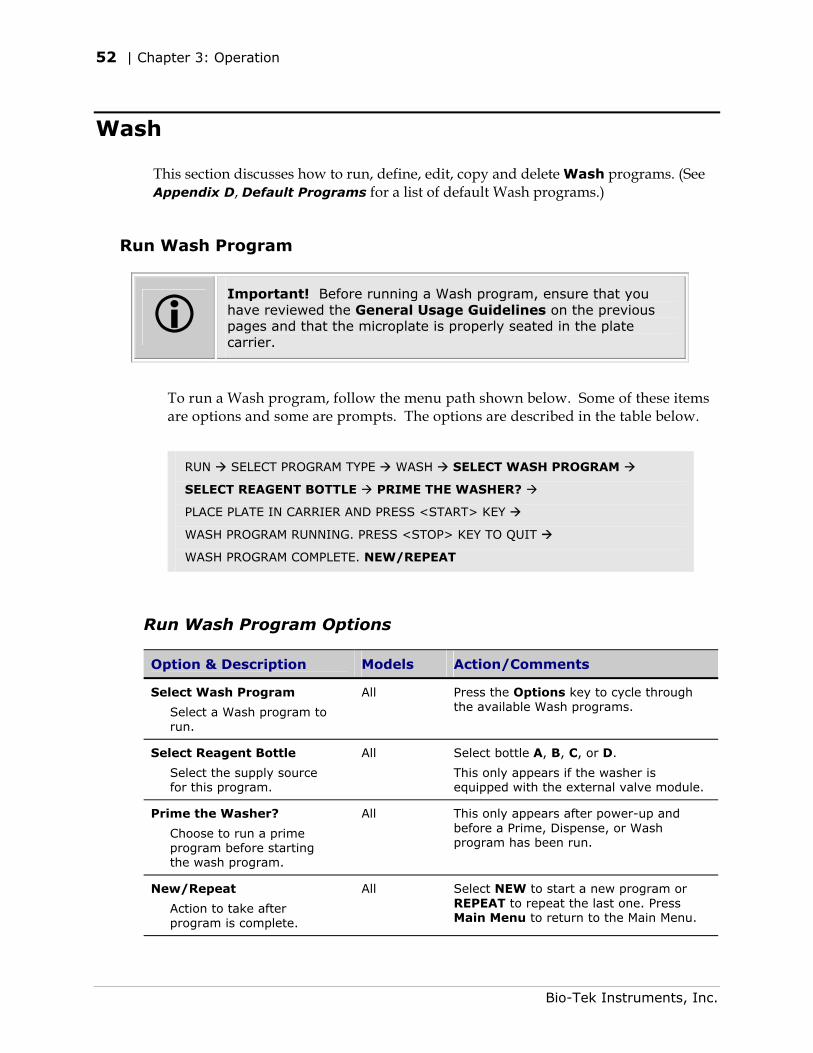
52 | Chapter 3: Operation
Wash
This section discusses how to run, define, edit, copy and delete Wash programs. (See Appendix D, Default Programs for a list of default Wash programs.)
Run Wash Program
Important! Before running a Wash program, ensure that you have reviewed the General Usage Guidelines on the previous pages and that the microplate is properly seated in the plate carrier.
To run a Wash program, follow the menu path shown below. Some of these items are options and some are prompts. The options are described in the table below.
RUN SELECT PROGRAM TYPE WASH SELECT WASH PROGRAM
SELECT REAGENT BOTTLE PRIME THE WASHER?
PLACE PLATE IN CARRIER AND PRESS <START> KEY
WASH PROGRAM RUNNING. PRESS <STOP> KEY TO QUIT
WASH PROGRAM COMPLETE. NEW/REPEAT
Run Wash Program Options
Option & Description Models Action/Comments
Select Wash Program
Select a Wash program to run.
All
Press the Options key to cycle through the available Wash programs.
Select Reagent Bottle
Select the supply source for this program.
All Select bottle A, B, C, or D.
This only appears if the washer is equipped with the external valve module.
Prime the Washer?
Choose to run a prime program before starting the wash program.
All This only appears after power-up and before a Prime, Dispense, or Wash program has been run.
New/Repeat
Action to take after program is complete.
All Select NEW to start a new program or REPEAT to repeat the last one. Press Main Menu to return to the Main Menu.
Bio-Tek Instruments, Inc.
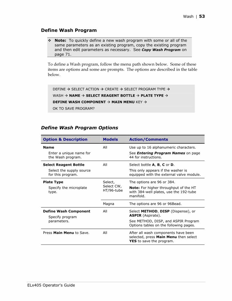
Wash | 53
Define Wash Program
Note: To quickly define a new wash program with some or all of the same parameters as an existing program, copy the existing program and then edit parameters as necessary. See Copy Wash Program on page 71.
To define a Wash program, follow the menu path shown below. Some of these items are options and some are prompts. The options are described in the table below.
DEFINE SELECT ACTION CREATE SELECT PROGRAM TYPE
WASH NAME SELECT REAGENT BOTTLE PLATE TYPE
DEFINE WASH COMPONENT MAIN MENU KEY
OK TO SAVE PROGRAM?
Define Wash Program Options
Option & Description Models Action/Comments
Name
Enter a unique name for the Wash program.
All Use up to 16 alphanumeric characters.
See Entering Program Names on page 44 for instructions.
Select Reagent Bottle
Select the supply source for this program.
All Select bottle A, B, C or D.
This only appears if the washer is equipped with the external valve module.
Select, Select CW, HT/96-tube
The options are 96 or 384.
Note: For higher throughput of the HT with 384-well plates, use the 192-tube manifold.
Plate Type
Specify the microplate type.
Magna The options are 96 or 96Bead.
Define Wash Component
Specify program parameters.
All Select METHOD, DISP (Dispense), or ASPIR (Aspirate).
See METHOD, DISP, and ASPIR Program Options tables on the following pages.
Press Main Menu to Save.
All After all wash components have been selected, press Main Menu then select YES to save the program.
ELx405 Operator's Guide
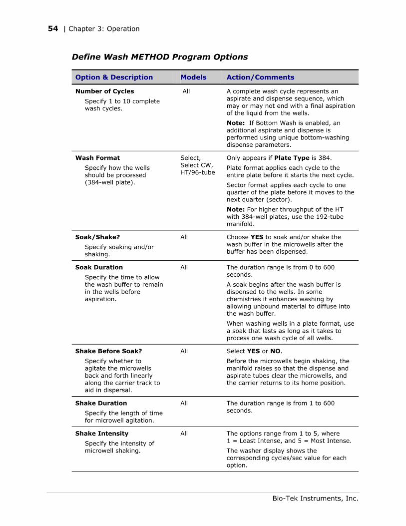
54 | Chapter 3: Operation
Define Wash METHOD Program Options
Option & Description Models Action/Comments
Number of Cycles
Specify 1 to 10 complete wash cycles.
All A complete wash cycle represents an aspirate and dispense sequence, which may or may not end with a final aspiration of the liquid from the wells.
Note: If Bottom Wash is enabled, an additional aspirate and dispense is performed using unique bottom-washing dispense parameters.
Wash Format
Specify how the wells should be processed (384-well plate).
Select, Select CW, HT/96-tube
Only appears if Plate Type is 384.
Plate format applies each cycle to the entire plate before it starts the next cycle.
Sector format applies each cycle to one quarter of the plate before it moves to the next quarter (sector).
Note: For higher throughput of the HT with 384-well plates, use the 192-tube manifold.
Soak/Shake?
Specify soaking and/or shaking.
All Choose YES to soak and/or shake the wash buffer in the microwells after the buffer has been dispensed.
Soak Duration
Specify the time to allow the wash buffer to remain in the wells before aspiration.
All The duration range is from 0 to 600 seconds.
A soak begins after the wash buffer is dispensed to the wells. In some chemistries it enhances washing by allowing unbound material to diffuse into the wash buffer.
When washing wells in a plate format, use a soak that lasts as long as it takes to process one wash cycle of all wells.
Shake Before Soak?
Specify whether to agitate the microwells back and forth linearly along the carrier track to aid in dispersal.
All Select YES or NO.
Before the microwells begin shaking, the manifold raises so that the dispense and aspirate tubes clear the microwells, and the carrier returns to its home position.
Shake Duration
Specify the length of time for microwell agitation.
All The duration range is from 1 to 600 seconds.
Shake Intensity
Specify the intensity of microwell shaking.
All The options range from 1 to 5, where 1 = Least Intense, and 5 = Most Intense.
The washer display shows the corresponding cycles/sec value for each option.
Bio-Tek Instruments, Inc.
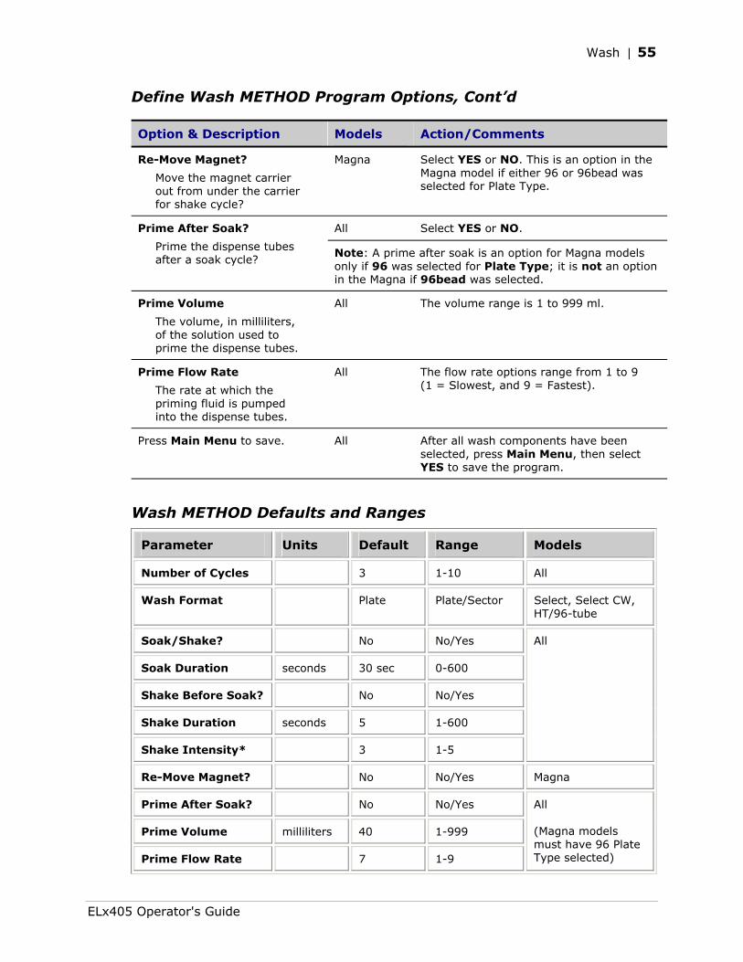
Wash | 55
Define Wash METHOD Program Options, Cont’d
Option & Description Models Action/Comments
Re-Move Magnet?
Move the magnet carrier out from under the carrier for shake cycle?
Magna Select YES or NO. This is an option in the Magna model if either 96 or 96bead was selected for Plate Type.
All Select YES or NO. Prime After Soak?
Prime the dispense tubes after a soak cycle?
Note: A prime after soak is an option for Magna models only if 96 was selected for Plate Type; it is not an option in the Magna if 96bead was selected.
Prime Volume
The volume, in milliliters, of the solution used to prime the dispense tubes.
All The volume range is 1 to 999 ml.
Prime Flow Rate
The rate at which the priming fluid is pumped into the dispense tubes.
All The flow rate options range from 1 to 9 (1 = Slowest, and 9 = Fastest).
Press Main Menu to save.
All After all wash components have been selected, press Main Menu, then select YES to save the program.
Wash METHOD Defaults and Ranges
Parameter Units Default Range Models
Number of Cycles 3 1-10 All
Wash Format Plate Plate/Sector Select, Select CW, HT/96-tube
Soak/Shake? No No/Yes
Soak Duration seconds 30 sec 0-600
Shake Before Soak? No No/Yes
Shake Duration seconds 5 1-600
Shake Intensity* 3 1-5
All
Re-Move Magnet? No No/Yes Magna
Prime After Soak? No No/Yes
Prime Volume milliliters 40 1-999
Prime Flow Rate 7 1-9
All (Magna models must have 96 Plate Type selected)
ELx405 Operator's Guide
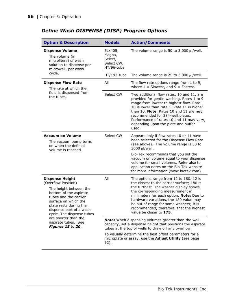
56 | Chapter 3: Operation
Define Wash DISPENSE (DISP) Program Options
Option & Description Models Action/Comments
ELx405, Magna, Select, Select CW, HT/96-tube
The volume range is 50 to 3,000 µl/well. Dispense Volume
The volume (in microliters) of wash solution to dispense per microwell, per wash cycle. HT/192-tube The volume range is 25 to 3,000 µl/well.
All The flow rate options range from 1 to 9, where 1 = Slowest, and 9 = Fastest.
Dispense Flow Rate
The rate at which the fluid is dispensed from the tubes.
Select CW Two additional flow rates, 10 and 11, are provided for gentle washing. Rates 1 to 9 range from lowest to highest flow. Rate 10 is lower than rate 1. Rate 11 is higher than 10. Note: Rates 10 and 11 are not recommended for 384-well plates. Performance of rates 10 and 11 may vary, depending upon the plate and buffer used.
Vacuum on Volume
The vacuum pump turns on when the defined volume is reached.
Select CW Appears only if flow rates 10 or 11 have been selected for the Dispense Flow Rate (see above). The volume range is 50 to 3000 µl/well.
Bio-Tek recommends that you set the vacuum on volume equal to your dispense volume for small volumes. Refer also to application notes on the Bio-Tek website for more information (www.biotek.com).
All The options range from 12 to 180. 12 is the closest to the carrier surface; 180 is the furthest. The washer display shows the corresponding measurement in millimeters for each option. Note: Due to hardware variations, the 180 value may be out of range for some washers; it is recommended, therefore, that the highest value be closer to 175.
Dispense Height (Overflow Position)
The height between the bottom of the aspirate tubes and the carrier surface on which the plate rests during the dispense part of a wash cycle. The dispense tubes are shorter than the aspirate tubes. See Figures 18 to 20.
Note: When dispensing volumes greater than the well capacity, set a dispense height that positions the aspirate tubes at the top of wells to draw off any overflow.
To visually determine the best offset parameters for a microplate or assay, use the Adjust Utility (see page 92).
Bio-Tek Instruments, Inc.
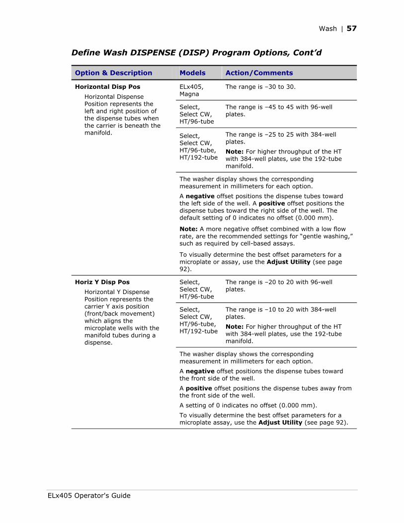
Wash | 57
Define Wash DISPENSE (DISP) Program Options, Cont’d
Option & Description Models Action/Comments
ELx405, Magna
The range is –30 to 30.
Select, Select CW, HT/96-tube
The range is –45 to 45 with 96-well plates.
Select, Select CW, HT/96-tube, HT/192-tube
The range is –25 to 25 with 384-well plates.
Note: For higher throughput of the HT with 384-well plates, use the 192-tube manifold.
Horizontal Disp Pos
Horizontal Dispense Position represents the left and right position of the dispense tubes when the carrier is beneath the manifold.
The washer display shows the corresponding measurement in millimeters for each option.
A negative offset positions the dispense tubes toward the left side of the well. A positive offset positions the dispense tubes toward the right side of the well. The default setting of 0 indicates no offset (0.000 mm).
Note: A more negative offset combined with a low flow rate, are the recommended settings for “gentle washing,” such as required by cell-based assays.
To visually determine the best offset parameters for a microplate or assay, use the Adjust Utility (see page 92).
Select, Select CW, HT/96-tube
The range is –20 to 20 with 96-well plates.
Select, Select CW, HT/96-tube, HT/192-tube
The range is –10 to 20 with 384-well plates.
Note: For higher throughput of the HT with 384-well plates, use the 192-tube manifold.
Horiz Y Disp Pos
Horizontal Y Dispense Position represents the carrier Y axis position (front/back movement) which aligns the microplate wells with the manifold tubes during a dispense.
The washer display shows the corresponding measurement in millimeters for each option.
A negative offset positions the dispense tubes toward the front side of the well.
A positive offset positions the dispense tubes away from the front side of the well.
A setting of 0 indicates no offset (0.000 mm).
To visually determine the best offset parameters for a microplate assay, use the Adjust Utility (see page 92).
ELx405 Operator's Guide
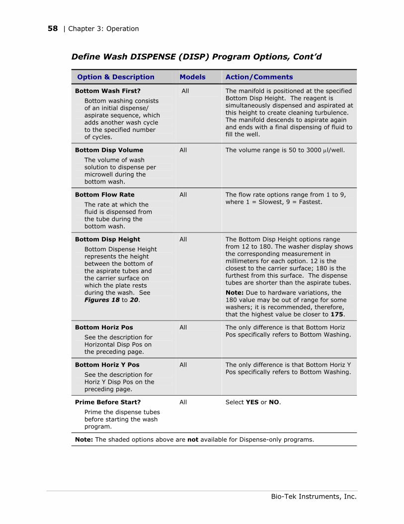
58 | Chapter 3: Operation
Define Wash DISPENSE (DISP) Program Options, Cont’d
Option & Description Models Action/Comments
Bottom Wash First?
Bottom washing consists of an initial dispense/ aspirate sequence, which adds another wash cycle to the specified number of cycles.
All The manifold is positioned at the specified Bottom Disp Height. The reagent is simultaneously dispensed and aspirated at this height to create cleaning turbulence. The manifold descends to aspirate again and ends with a final dispensing of fluid to fill the well.
Bottom Disp Volume
The volume of wash solution to dispense per microwell during the bottom wash.
All The volume range is 50 to 3000 µl/well.
Bottom Flow Rate
The rate at which the fluid is dispensed from the tube during the bottom wash.
All The flow rate options range from 1 to 9, where 1 = Slowest, 9 = Fastest.
Bottom Disp Height
Bottom Dispense Height represents the height between the bottom of the aspirate tubes and the carrier surface on which the plate rests during the wash. See Figures 18 to 20.
All The Bottom Disp Height options range from 12 to 180. The washer display shows the corresponding measurement in millimeters for each option. 12 is the closest to the carrier surface; 180 is the furthest from this surface. The dispense tubes are shorter than the aspirate tubes.
Note: Due to hardware variations, the 180 value may be out of range for some washers; it is recommended, therefore, that the highest value be closer to 175.
Bottom Horiz Pos
See the description for Horizontal Disp Pos on the preceding page.
All The only difference is that Bottom Horiz Pos specifically refers to Bottom Washing.
Bottom Horiz Y Pos
See the description for Horiz Y Disp Pos on the preceding page.
All The only difference is that Bottom Horiz Y Pos specifically refers to Bottom Washing.
Prime Before Start?
Prime the dispense tubes before starting the wash program.
All Select YES or NO.
Note: The shaded options above are not available for Dispense-only programs.
Bio-Tek Instruments, Inc.
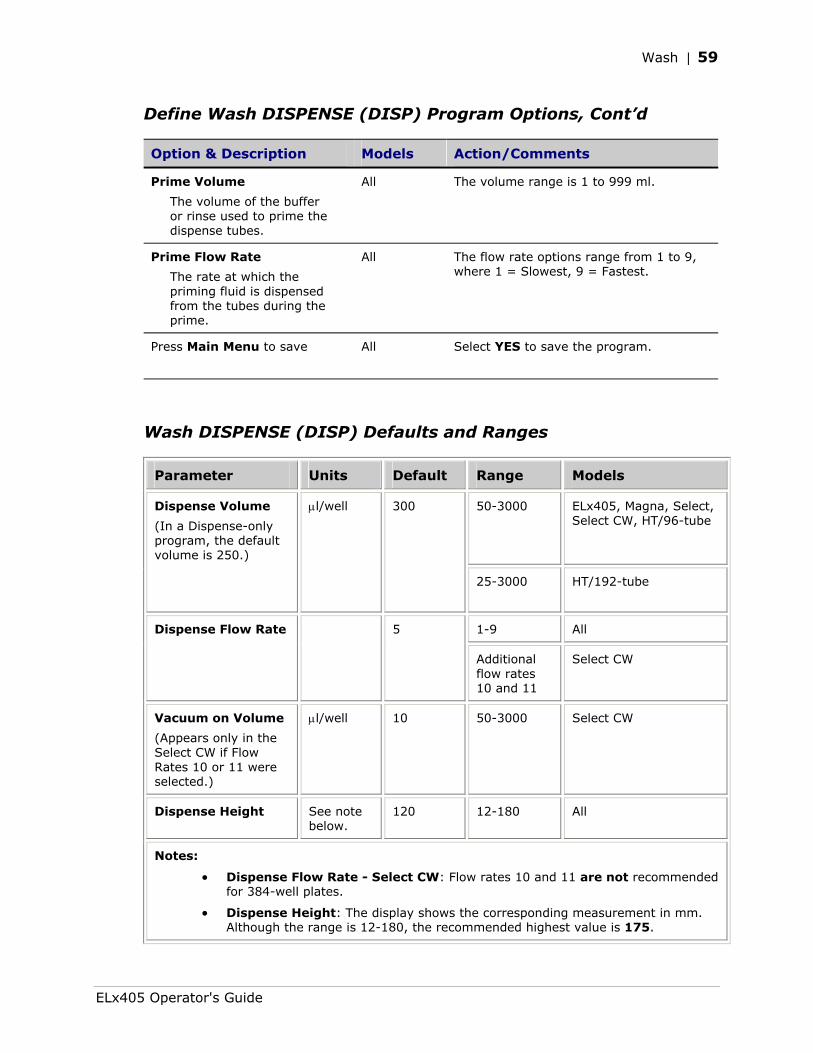
Wash | 59
Define Wash DISPENSE (DISP) Program Options, Cont’d
Option & Description Models Action/Comments
Prime Volume
The volume of the buffer or rinse used to prime the dispense tubes.
All The volume range is 1 to 999 ml.
Prime Flow Rate
The rate at which the priming fluid is dispensed from the tubes during the prime.
All The flow rate options range from 1 to 9, where 1 = Slowest, 9 = Fastest.
Press Main Menu to save
All Select YES to save the program.
Wash DISPENSE (DISP) Defaults and Ranges
Parameter Units Default Range Models
50-3000 ELx405, Magna, Select, Select CW, HT/96-tube
Dispense Volume
(In a Dispense-only program, the default volume is 250.)
µl/well 300
25-3000 HT/192-tube
1-9 All Dispense Flow Rate 5
Additional flow rates 10 and 11
Select CW
Vacuum on Volume
(Appears only in the Select CW if Flow Rates 10 or 11 were selected.)
µl/well 10 50-3000 Select CW
Dispense Height See note below.
120 12-180 All
Notes:
• Dispense Flow Rate - Select CW: Flow rates 10 and 11 are not recommended for 384-well plates.
• Dispense Height: The display shows the corresponding measurement in mm. Although the range is 12-180, the recommended highest value is 175.
ELx405 Operator's Guide
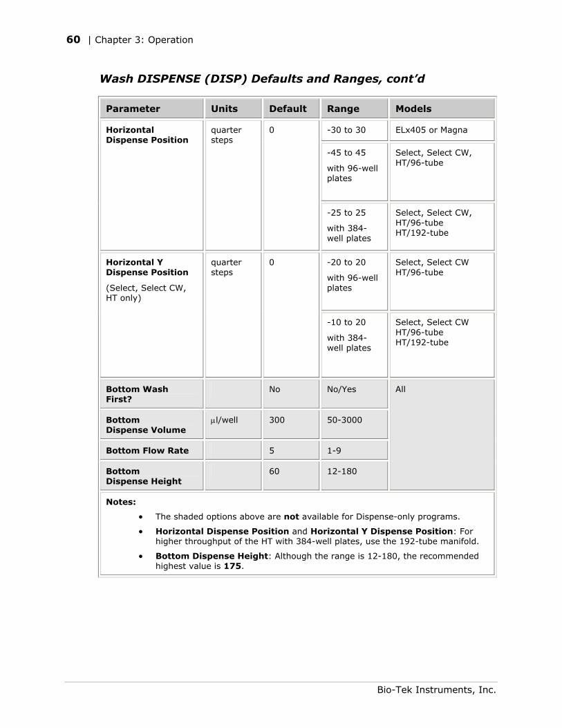
60 | Chapter 3: Operation
Wash DISPENSE (DISP) Defaults and Ranges, cont’d
Parameter Units Default Range Models
-30 to 30 ELx405 or Magna
-45 to 45
with 96-well plates
Select, Select CW, HT/96-tube
Horizontal Dispense Position
quarter steps
0
-25 to 25
with 384-well plates
Select, Select CW, HT/96-tube HT/192-tube
-20 to 20
with 96-well plates
Select, Select CW HT/96-tube
Horizontal Y Dispense Position
(Select, Select CW, HT only)
quarter steps
0
-10 to 20
with 384-well plates
Select, Select CW HT/96-tube HT/192-tube
Bottom Wash First?
No No/Yes
Bottom Dispense Volume
µl/well 300 50-3000
Bottom Flow Rate 5 1-9
Bottom Dispense Height
60 12-180
All
Notes:
• The shaded options above are not available for Dispense-only programs.
• Horizontal Dispense Position and Horizontal Y Dispense Position: For higher throughput of the HT with 384-well plates, use the 192-tube manifold.
• Bottom Dispense Height: Although the range is 12-180, the recommended highest value is 175.
Bio-Tek Instruments, Inc.
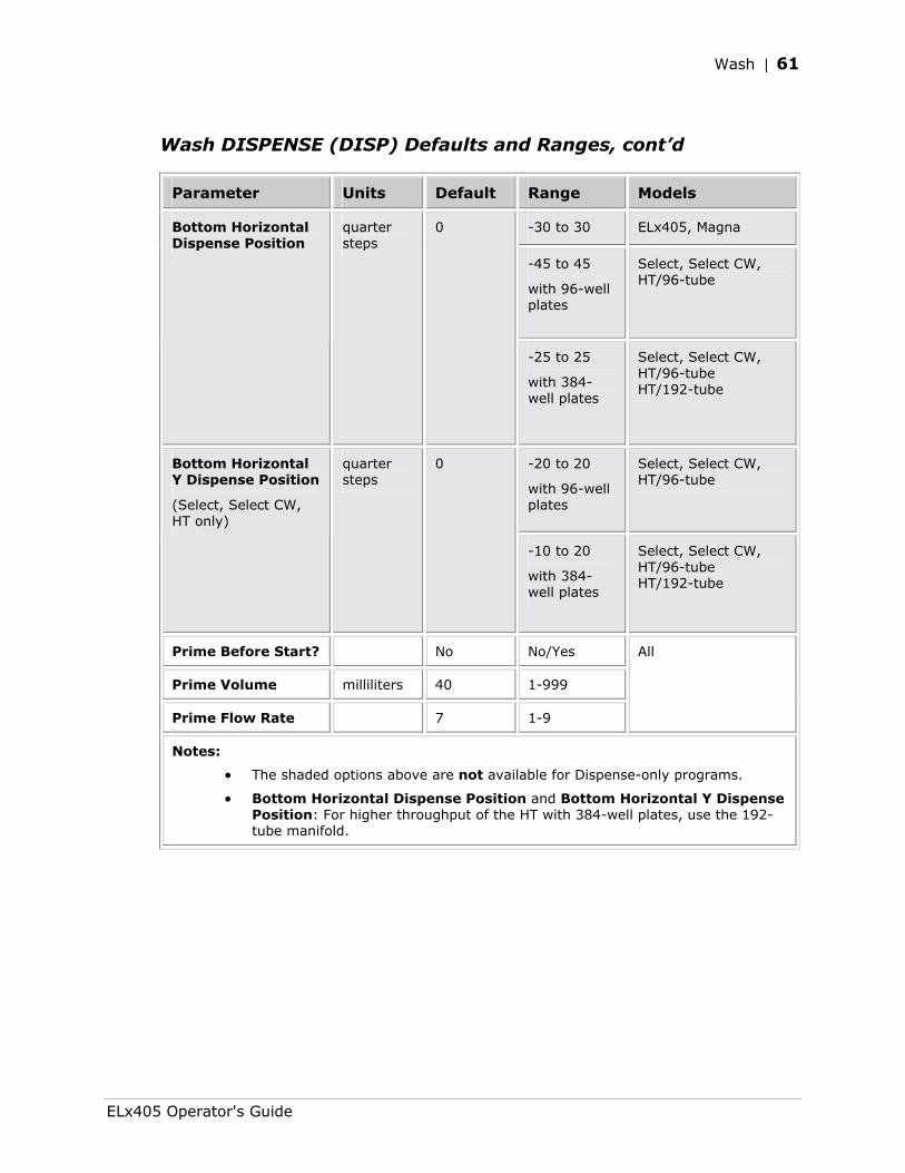
Wash | 61
Wash DISPENSE (DISP) Defaults and Ranges, cont’d
Parameter Units Default Range Models
-30 to 30 ELx405, Magna
-45 to 45
with 96-well plates
Select, Select CW, HT/96-tube
Bottom Horizontal Dispense Position
quarter steps
0
-25 to 25
with 384-well plates
Select, Select CW, HT/96-tube HT/192-tube
-20 to 20
with 96-well plates
Select, Select CW, HT/96-tube
Bottom Horizontal Y Dispense Position
(Select, Select CW, HT only)
quarter steps
0
-10 to 20
with 384-well plates
Select, Select CW, HT/96-tube HT/192-tube
Prime Before Start? No No/Yes
Prime Volume milliliters 40 1-999
Prime Flow Rate 7 1-9
All
Notes:
• The shaded options above are not available for Dispense-only programs.
• Bottom Horizontal Dispense Position and Bottom Horizontal Y Dispense Position: For higher throughput of the HT with 384-well plates, use the 192-tube manifold.
ELx405 Operator's Guide
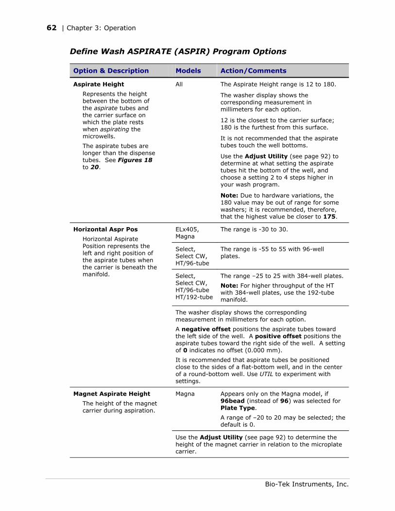
62 | Chapter 3: Operation
Define Wash ASPIRATE (ASPIR) Program Options
Option & Description Models Action/Comments
Aspirate Height
Represents the height between the bottom of the aspirate tubes and the carrier surface on which the plate rests when aspirating the microwells.
The aspirate tubes are longer than the dispense tubes. See Figures 18 to 20.
All The Aspirate Height range is 12 to 180.
The washer display shows the corresponding measurement in millimeters for each option.
12 is the closest to the carrier surface; 180 is the furthest from this surface.
It is not recommended that the aspirate tubes touch the well bottoms.
Use the Adjust Utility (see page 92) to determine at what setting the aspirate tubes hit the bottom of the well, and choose a setting 2 to 4 steps higher in your wash program.
Note: Due to hardware variations, the 180 value may be out of range for some washers; it is recommended, therefore, that the highest value be closer to 175.
ELx405, Magna
The range is -30 to 30.
Select, Select CW, HT/96-tube
The range is -55 to 55 with 96-well plates.
Select, Select CW, HT/96-tube HT/192-tube
The range –25 to 25 with 384-well plates.
Note: For higher throughput of the HT with 384-well plates, use the 192-tube manifold.
Horizontal Aspr Pos
Horizontal Aspirate Position represents the left and right position of the aspirate tubes when the carrier is beneath the manifold.
The washer display shows the corresponding measurement in millimeters for each option.
A negative offset positions the aspirate tubes toward the left side of the well. A positive offset positions the aspirate tubes toward the right side of the well. A setting of 0 indicates no offset (0.000 mm).
It is recommended that aspirate tubes be positioned close to the sides of a flat-bottom well, and in the center of a round-bottom well. Use UTIL to experiment with settings.
Magna Appears only on the Magna model, if 96bead (instead of 96) was selected for Plate Type.
A range of –20 to 20 may be selected; the default is 0.
Magnet Aspirate Height
The height of the magnet carrier during aspiration.
Use the Adjust Utility (see page 92) to determine the height of the magnet carrier in relation to the microplate carrier.
Bio-Tek Instruments, Inc.
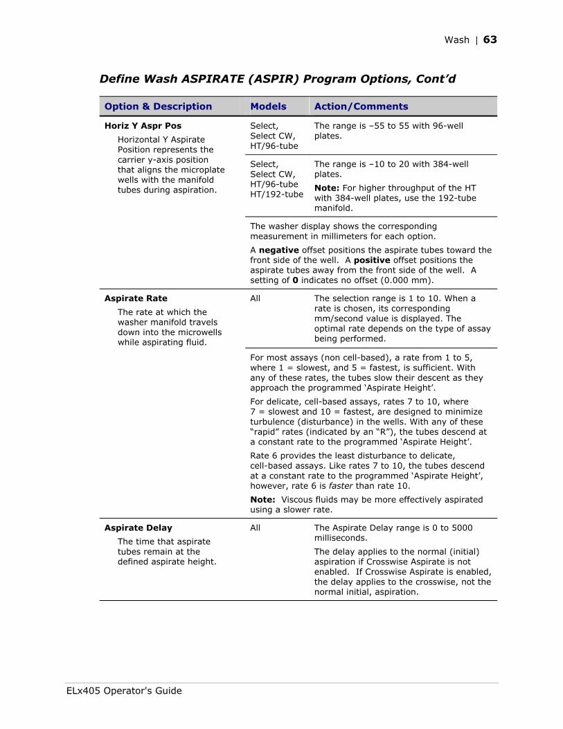
Wash | 63
Define Wash ASPIRATE (ASPIR) Program Options, Cont’d
Option & Description Models Action/Comments
Select, Select CW, HT/96-tube
The range is –55 to 55 with 96-well plates.
Select, Select CW, HT/96-tube HT/192-tube
The range is –10 to 20 with 384-well plates.
Note: For higher throughput of the HT with 384-well plates, use the 192-tube manifold.
Horiz Y Aspr Pos
Horizontal Y Aspirate Position represents the carrier y-axis position that aligns the microplate wells with the manifold tubes during aspiration.
The washer display shows the corresponding measurement in millimeters for each option.
A negative offset positions the aspirate tubes toward the front side of the well. A positive offset positions the aspirate tubes away from the front side of the well. A setting of 0 indicates no offset (0.000 mm).
All The selection range is 1 to 10. When a rate is chosen, its corresponding mm/second value is displayed. The optimal rate depends on the type of assay being performed.
Aspirate Rate
The rate at which the washer manifold travels down into the microwells while aspirating fluid.
For most assays (non cell-based), a rate from 1 to 5, where 1 = slowest, and 5 = fastest, is sufficient. With any of these rates, the tubes slow their descent as they approach the programmed ‘Aspirate Height’.
For delicate, cell-based assays, rates 7 to 10, where 7 = slowest and 10 = fastest, are designed to minimize turbulence (disturbance) in the wells. With any of these “rapid” rates (indicated by an “R”), the tubes descend at a constant rate to the programmed ‘Aspirate Height’.
Rate 6 provides the least disturbance to delicate, cell-based assays. Like rates 7 to 10, the tubes descend at a constant rate to the programmed ‘Aspirate Height’, however, rate 6 is faster than rate 10.
Note: Viscous fluids may be more effectively aspirated using a slower rate.
Aspirate Delay
The time that aspirate tubes remain at the defined aspirate height.
All The Aspirate Delay range is 0 to 5000 milliseconds.
The delay applies to the normal (initial) aspiration if Crosswise Aspirate is not enabled. If Crosswise Aspirate is enabled, the delay applies to the crosswise, not the normal initial, aspiration.
ELx405 Operator's Guide
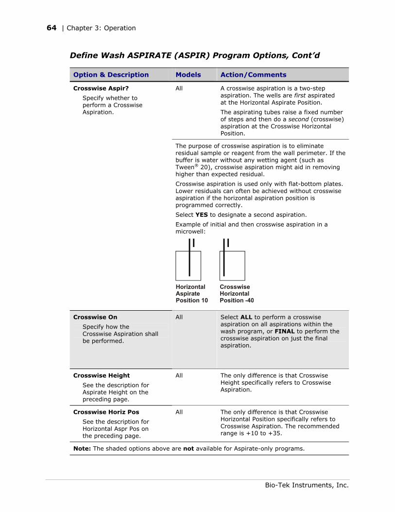
64 | Chapter 3: Operation
Define Wash ASPIRATE (ASPIR) Program Options, Cont’d
Option & Description Models Action/Comments
All A crosswise aspiration is a two-step aspiration. The wells are first aspirated at the Horizontal Aspirate Position.
The aspirating tubes raise a fixed number of steps and then do a second (crosswise) aspiration at the Crosswise Horizontal Position.
Crosswise Aspir?
Specify whether to perform a Crosswise Aspiration.
The purpose of crosswise aspiration is to eliminate residual sample or reagent from the wall perimeter. If the buffer is water without any wetting agent (such as Tween® 20), crosswise aspiration might aid in removing higher than expected residual.
Crosswise aspiration is used only with flat-bottom plates. Lower residuals can often be achieved without crosswise aspiration if the horizontal aspiration position is programmed correctly.
Select YES to designate a second aspiration.
Example of initial and then crosswise aspiration in a microwell:
HorizontalAspiratePosition 10
CrosswiseHorizontalPosition -40
Crosswise On
Specify how the Crosswise Aspiration shall be performed.
All Select ALL to perform a crosswise aspiration on all aspirations within the wash program, or FINAL to perform the crosswise aspiration on just the final aspiration.
Crosswise Height
See the description for Aspirate Height on the preceding page.
All The only difference is that Crosswise Height specifically refers to Crosswise Aspiration.
Crosswise Horiz Pos
See the description for Horizontal Aspr Pos on the preceding page.
All The only difference is that Crosswise Horizontal Position specifically refers to Crosswise Aspiration. The recommended range is +10 to +35.
Note: The shaded options above are not available for Aspirate-only programs.
Bio-Tek Instruments, Inc.
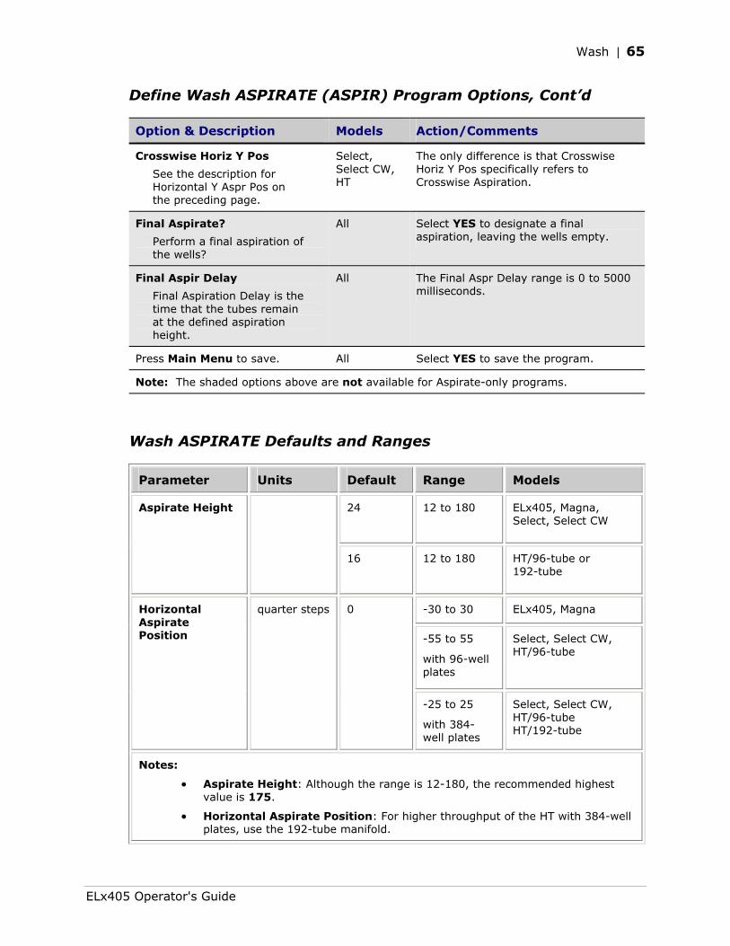
Wash | 65
Define Wash ASPIRATE (ASPIR) Program Options, Cont’d
Option & Description Models Action/Comments
Crosswise Horiz Y Pos
See the description for Horizontal Y Aspr Pos on the preceding page.
Select, Select CW, HT
The only difference is that Crosswise Horiz Y Pos specifically refers to Crosswise Aspiration.
Final Aspirate?
Perform a final aspiration of the wells?
All Select YES to designate a final aspiration, leaving the wells empty.
Final Aspir Delay
Final Aspiration Delay is the time that the tubes remain at the defined aspiration height.
All The Final Aspr Delay range is 0 to 5000 milliseconds.
Press Main Menu to save. All Select YES to save the program.
Note: The shaded options above are not available for Aspirate-only programs.
Wash ASPIRATE Defaults and Ranges
Parameter Units Default Range Models
24 12 to 180
ELx405, Magna, Select, Select CW
Aspirate Height
16 12 to 180 HT/96-tube or 192-tube
-30 to 30 ELx405, Magna
-55 to 55
with 96-well plates
Select, Select CW, HT/96-tube
Horizontal Aspirate Position
quarter steps 0
-25 to 25
with 384-well plates
Select, Select CW, HT/96-tube HT/192-tube
Notes:
• Aspirate Height: Although the range is 12-180, the recommended highest value is 175.
• Horizontal Aspirate Position: For higher throughput of the HT with 384-well plates, use the 192-tube manifold.
ELx405 Operator's Guide
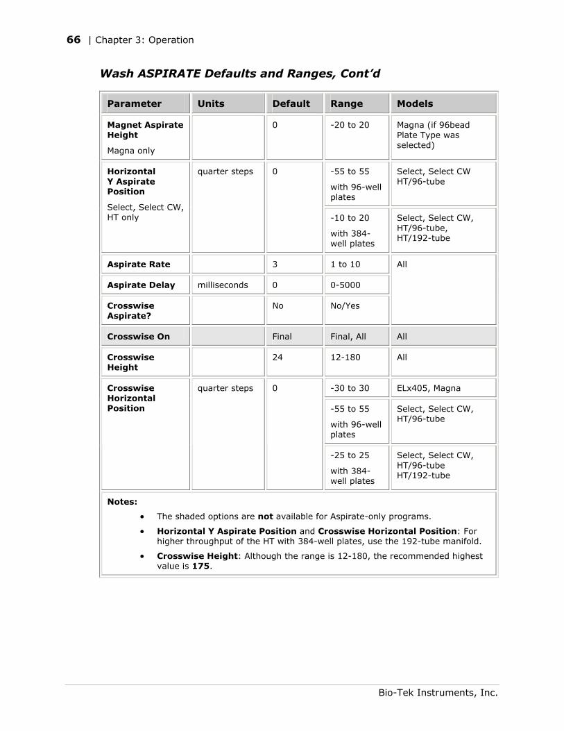
66 | Chapter 3: Operation
Wash ASPIRATE Defaults and Ranges, Cont’d
Parameter Units Default Range Models
Magnet Aspirate Height
Magna only
0 -20 to 20 Magna (if 96bead Plate Type was selected)
-55 to 55
with 96-well plates
Select, Select CW HT/96-tube
Horizontal Y Aspirate Position
Select, Select CW, HT only
quarter steps 0
-10 to 20
with 384-well plates
Select, Select CW, HT/96-tube, HT/192-tube
Aspirate Rate 3 1 to 10
Aspirate Delay milliseconds 0 0-5000
Crosswise Aspirate?
No No/Yes
All
Crosswise On Final Final, All All
Crosswise Height
24 12-180 All
-30 to 30 ELx405, Magna
-55 to 55
with 96-well plates
Select, Select CW, HT/96-tube
Crosswise Horizontal Position
quarter steps 0
-25 to 25
with 384-well plates
Select, Select CW, HT/96-tube HT/192-tube
Notes:
• The shaded options are not available for Aspirate-only programs.
• Horizontal Y Aspirate Position and Crosswise Horizontal Position: For higher throughput of the HT with 384-well plates, use the 192-tube manifold.
• Crosswise Height: Although the range is 12-180, the recommended highest value is 175.
Bio-Tek Instruments, Inc.
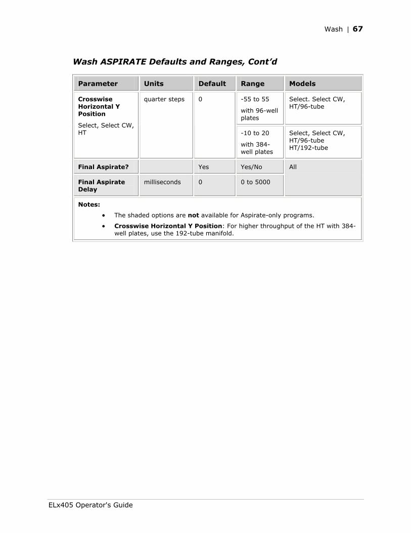
Wash | 67
Wash ASPIRATE Defaults and Ranges, Cont’d
Parameter Units Default Range Models
-55 to 55
with 96-well plates
Select. Select CW, HT/96-tube
Crosswise Horizontal Y Position
Select, Select CW, HT
quarter steps 0
-10 to 20
with 384-well plates
Select, Select CW, HT/96-tube HT/192-tube
Final Aspirate? Yes Yes/No
Final Aspirate Delay
milliseconds 0 0 to 5000
All
Notes:
• The shaded options are not available for Aspirate-only programs.
• Crosswise Horizontal Y Position: For higher throughput of the HT with 384-well plates, use the 192-tube manifold.
ELx405 Operator's Guide
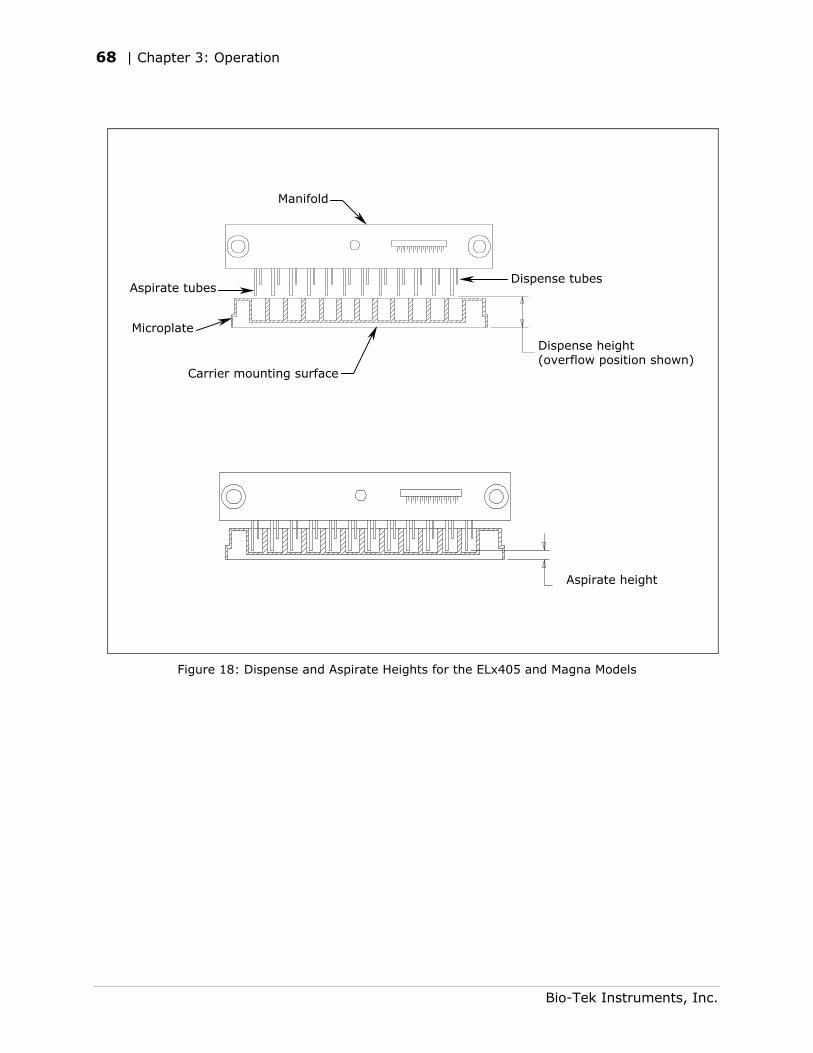
68 | Chapter 3: Operation
Aspirate height
Carrier mounting surface
Dispense tubes Aspirate tubes
Microplate
Manifold
Dispense height (overflow position shown)
Figure 18: Dispense and Aspirate Heights for the ELx405 and Magna Models
Bio-Tek Instruments, Inc.
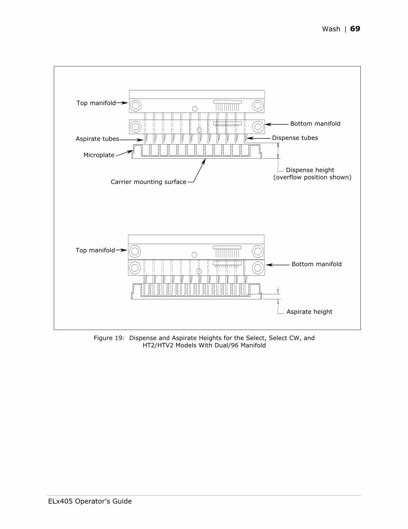
Wash | 69
Dispense height (overflow position shown)
Top manifold
Aspirate height
Bottom manifold
Top manifold
Microplate
Carrier mounting surface
Aspirate tubes Dispense tubes
Bottom manifold
Figure 19: Dispense and Aspirate Heights for the Select, Select CW, and HT2/HTV2 Models With Dual/96 Manifold
ELx405 Operator's Guide
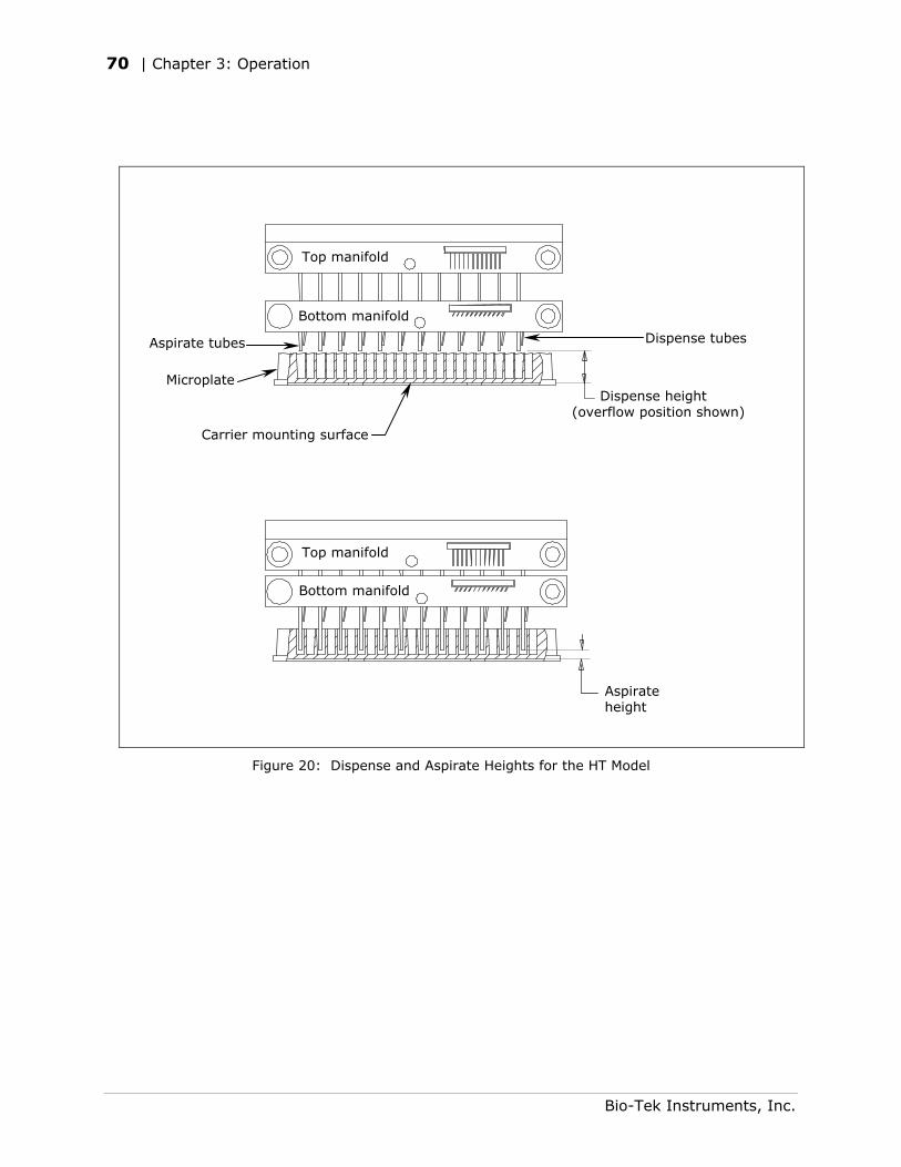
70 | Chapter 3: Operation
Top manifold
Bottom manifold
Aspirate tubes
Aspirate height
Bottom manifold
Top manifold
Dispense height (overflow position shown)
Carrier mounting surface
Microplate
Dispense tubes
Figure 20: Dispense and Aspirate Heights for the HT Model
Bio-Tek Instruments, Inc.
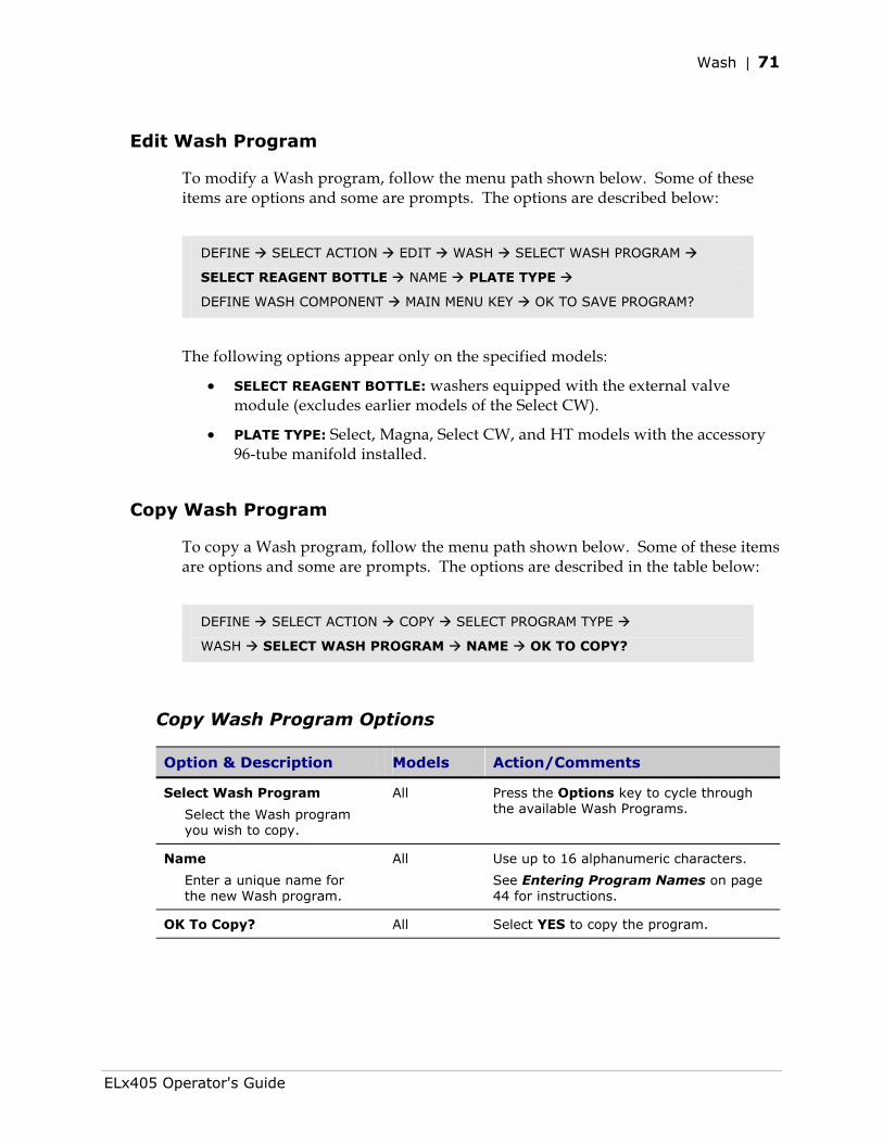
Wash | 71
Edit Wash Program
To modify a Wash program, follow the menu path shown below. Some of these items are options and some are prompts. The options are described below:
DEFINE SELECT ACTION EDIT WASH SELECT WASH PROGRAM
SELECT REAGENT BOTTLE NAME PLATE TYPE
DEFINE WASH COMPONENT MAIN MENU KEY OK TO SAVE PROGRAM?
The following options appear only on the specified models:
• SELECT REAGENT BOTTLE: washers equipped with the external valve module (excludes earlier models of the Select CW).
• PLATE TYPE: Select, Magna, Select CW, and HT models with the accessory 96-tube manifold installed.
Copy Wash Program
To copy a Wash program, follow the menu path shown below. Some of these items are options and some are prompts. The options are described in the table below:
DEFINE SELECT ACTION COPY SELECT PROGRAM TYPE
WASH SELECT WASH PROGRAM NAME OK TO COPY?
Copy Wash Program Options
Option & Description Models Action/Comments
Select Wash Program
Select the Wash program you wish to copy.
All
Press the Options key to cycle through the available Wash Programs.
Name
Enter a unique name for the new Wash program.
All Use up to 16 alphanumeric characters.
See Entering Program Names on page 44 for instructions.
OK To Copy? All Select YES to copy the program.
ELx405 Operator's Guide
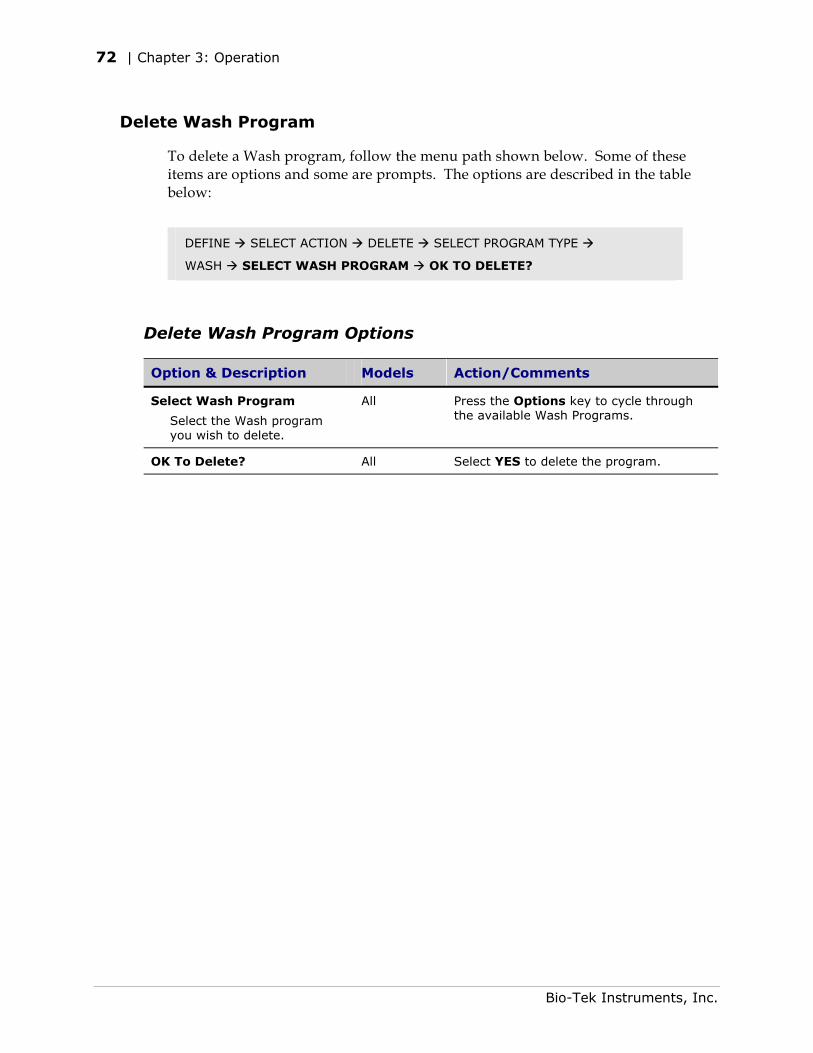
72 | Chapter 3: Operation
Delete Wash Program
To delete a Wash program, follow the menu path shown below. Some of these items are options and some are prompts. The options are described in the table below:
DEFINE SELECT ACTION DELETE SELECT PROGRAM TYPE
WASH SELECT WASH PROGRAM OK TO DELETE?
Delete Wash Program Options
Option & Description Models Action/Comments
Select Wash Program
Select the Wash program you wish to delete.
All
Press the Options key to cycle through the available Wash Programs.
OK To Delete? All Select YES to delete the program.
Bio-Tek Instruments, Inc.
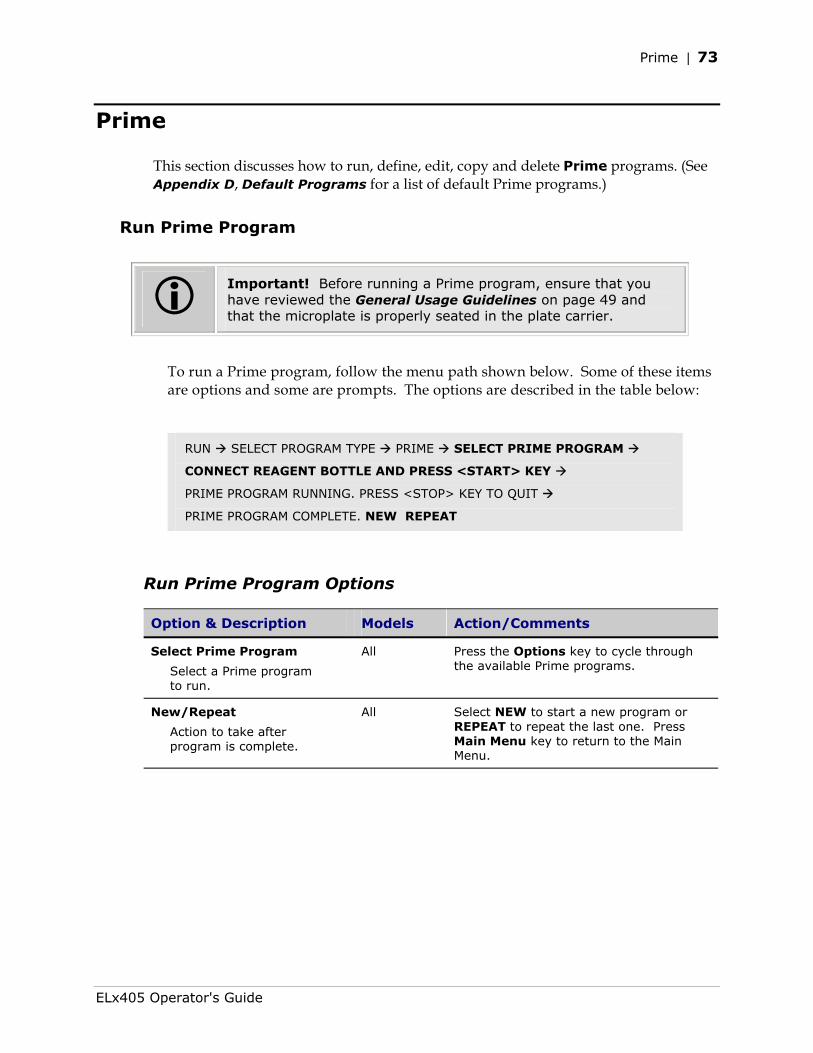
Prime | 73
Prime
This section discusses how to run, define, edit, copy and delete Prime programs. (See Appendix D, Default Programs for a list of default Prime programs.)
Run Prime Program
Important! Before running a Prime program, ensure that you have reviewed the General Usage Guidelines on page 49 and that the microplate is properly seated in the plate carrier.
To run a Prime program, follow the menu path shown below. Some of these items are options and some are prompts. The options are described in the table below:
RUN SELECT PROGRAM TYPE PRIME SELECT PRIME PROGRAM
CONNECT REAGENT BOTTLE AND PRESS <START> KEY
PRIME PROGRAM RUNNING. PRESS <STOP> KEY TO QUIT
PRIME PROGRAM COMPLETE. NEW REPEAT
Run Prime Program Options
Option & Description Models Action/Comments
Select Prime Program
Select a Prime program to run.
All
Press the Options key to cycle through the available Prime programs.
New/Repeat
Action to take after program is complete.
All Select NEW to start a new program or REPEAT to repeat the last one. Press Main Menu key to return to the Main Menu.
ELx405 Operator's Guide
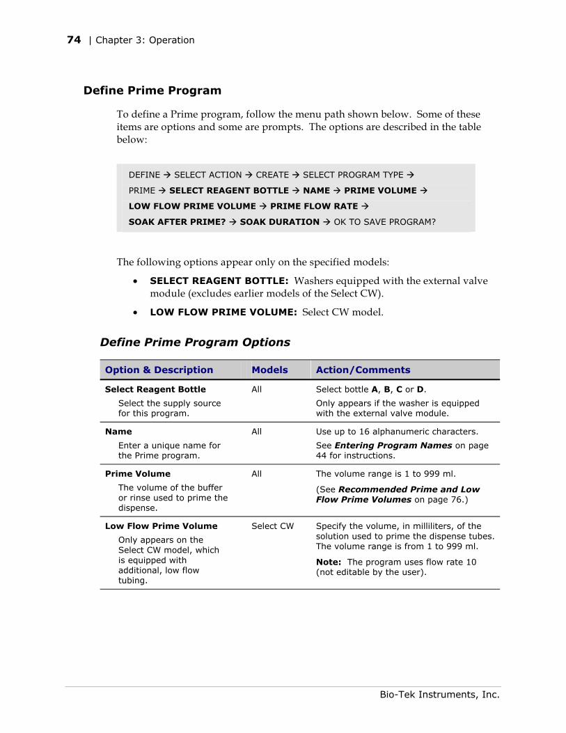
74 | Chapter 3: Operation
Define Prime Program
To define a Prime program, follow the menu path shown below. Some of these items are options and some are prompts. The options are described in the table below:
DEFINE SELECT ACTION CREATE SELECT PROGRAM TYPE
PRIME SELECT REAGENT BOTTLE NAME PRIME VOLUME
LOW FLOW PRIME VOLUME PRIME FLOW RATE
SOAK AFTER PRIME? SOAK DURATION OK TO SAVE PROGRAM?
The following options appear only on the specified models:
• SELECT REAGENT BOTTLE: Washers equipped with the external valve module (excludes earlier models of the Select CW).
• LOW FLOW PRIME VOLUME: Select CW model.
Define Prime Program Options
Option & Description Models Action/Comments
Select Reagent Bottle
Select the supply source for this program.
All
Select bottle A, B, C or D.
Only appears if the washer is equipped with the external valve module.
Name
Enter a unique name for the Prime program.
All Use up to 16 alphanumeric characters.
See Entering Program Names on page 44 for instructions.
Prime Volume
The volume of the buffer or rinse used to prime the dispense.
All The volume range is 1 to 999 ml.
(See Recommended Prime and Low Flow Prime Volumes on page 76.)
Low Flow Prime Volume
Only appears on the Select CW model, which is equipped with additional, low flow tubing.
Select CW Specify the volume, in milliliters, of the solution used to prime the dispense tubes. The volume range is from 1 to 999 ml.
Note: The program uses flow rate 10 (not editable by the user).
Bio-Tek Instruments, Inc.
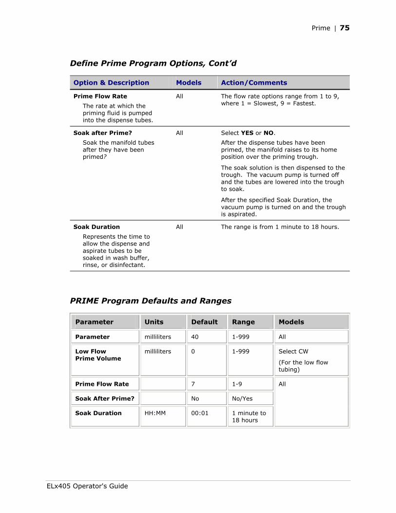
Prime | 75
Define Prime Program Options, Cont’d
Option & Description Models Action/Comments
Prime Flow Rate
The rate at which the priming fluid is pumped into the dispense tubes.
All
The flow rate options range from 1 to 9, where 1 = Slowest, 9 = Fastest.
Soak after Prime?
Soak the manifold tubes after they have been primed?
All Select YES or NO.
After the dispense tubes have been primed, the manifold raises to its home position over the priming trough.
The soak solution is then dispensed to the trough. The vacuum pump is turned off and the tubes are lowered into the trough to soak.
After the specified Soak Duration, the vacuum pump is turned on and the trough is aspirated.
Soak Duration
Represents the time to allow the dispense and aspirate tubes to be soaked in wash buffer, rinse, or disinfectant.
All The range is from 1 minute to 18 hours.
PRIME Program Defaults and Ranges
Parameter Units Default Range Models
Parameter milliliters 40 1-999 All
Low Flow Prime Volume
milliliters 0 1-999 Select CW
(For the low flow tubing)
Prime Flow Rate 7 1-9
Soak After Prime? No No/Yes
Soak Duration HH:MM 00:01 1 minute to 18 hours
All
ELx405 Operator's Guide
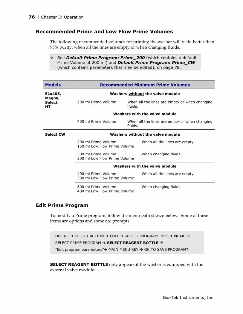
76 | Chapter 3: Operation
Recommended Prime and Low Flow Prime Volumes
The following recommended volumes for priming the washer will yield better than 95% purity, when all the lines are empty or when changing fluids.
See Default Prime Program: Prime_200 (which contains a default Prime Volume of 200 ml) and Default Prime Program: Prime_CW (which contains parameters that may be edited), on page 78.
Models Recommended Minimum Prime Volumes
Washers without the valve module
200 ml Prime Volume When all the lines are empty or when changing fluids.
Washers with the valve module
ELx405, Magna, Select, HT
400 ml Prime Volume When all the lines are empty or when changing fluids.
Washers without the valve module
200 ml Prime Volume 150 ml Low Flow Prime Volume
When all the lines are empty.
Select CW
300 ml Prime Volume 200 ml Low Flow Prime Volume
When changing fluids.
Washers with the valve module
400 ml Prime Volume 300 ml Low Flow Prime Volume
When all the lines are empty.
600 ml Prime Volume 400 ml Low Flow Prime Volume
When changing fluids.
Edit Prime Program
To modify a Prime program, follow the menu path shown below. Some of these items are options and some are prompts.
DEFINE SELECT ACTION EDIT SELECT PROGRAM TYPE PRIME
SELECT PRIME PROGRAM SELECT REAGENT BOTTLE
”Edit program parameters” MAIN MENU KEY OK TO SAVE PROGRAM?
SELECT REAGENT BOTTLE only appears if the washer is equipped with the external valve module.
Bio-Tek Instruments, Inc.
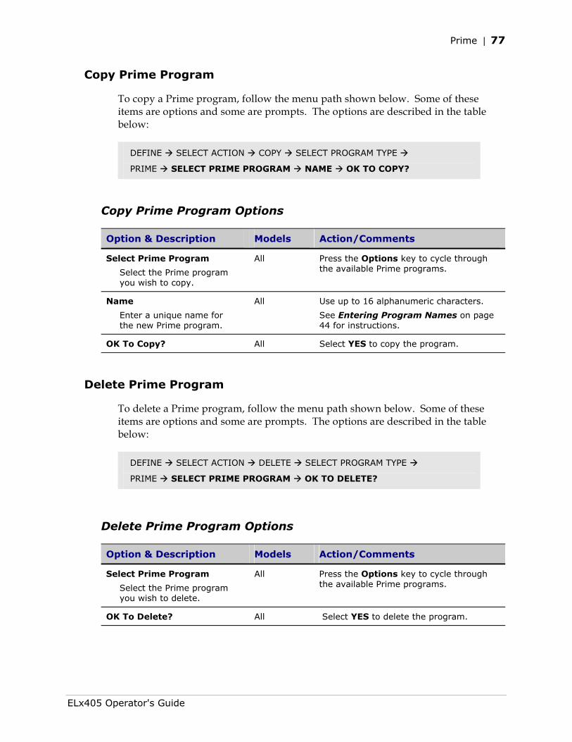
Prime | 77
Copy Prime Program
To copy a Prime program, follow the menu path shown below. Some of these items are options and some are prompts. The options are described in the table below:
DEFINE SELECT ACTION COPY SELECT PROGRAM TYPE
PRIME SELECT PRIME PROGRAM NAME OK TO COPY?
Copy Prime Program Options
Option & Description Models Action/Comments
Select Prime Program
Select the Prime program you wish to copy.
All
Press the Options key to cycle through the available Prime programs.
Name
Enter a unique name for the new Prime program.
All Use up to 16 alphanumeric characters.
See Entering Program Names on page 44 for instructions.
OK To Copy? All Select YES to copy the program.
Delete Prime Program
To delete a Prime program, follow the menu path shown below. Some of these items are options and some are prompts. The options are described in the table below:
DEFINE SELECT ACTION DELETE SELECT PROGRAM TYPE
PRIME SELECT PRIME PROGRAM OK TO DELETE?
Delete Prime Program Options
Option & Description Models Action/Comments
Select Prime Program
Select the Prime program you wish to delete.
All
Press the Options key to cycle through the available Prime programs.
OK To Delete? All Select YES to delete the program.
ELx405 Operator's Guide
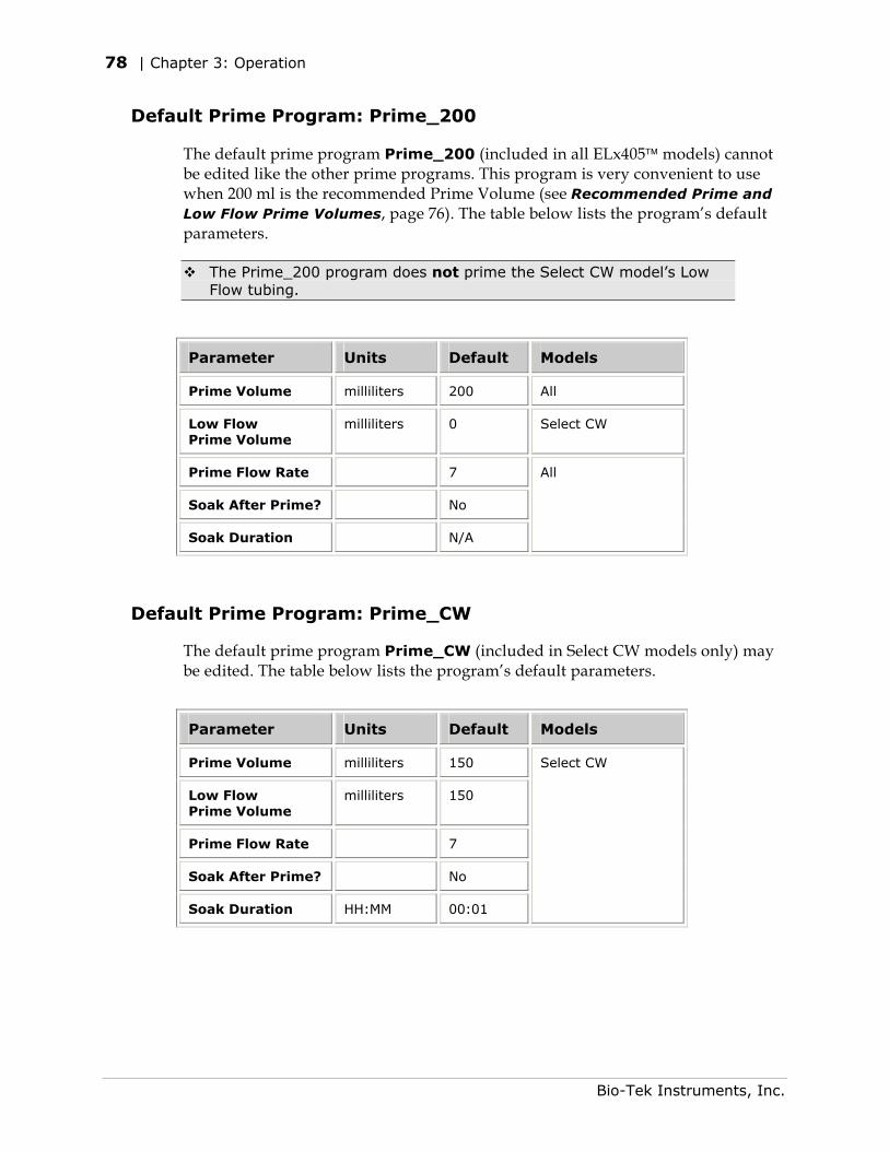
78 | Chapter 3: Operation
Default Prime Program: Prime_200
The default prime program Prime_200 (included in all ELx405 models) cannot be edited like the other prime programs. This program is very convenient to use when 200 ml is the recommended Prime Volume (see Recommended Prime and Low Flow Prime Volumes, page 76). The table below lists the program’s default parameters.
The Prime_200 program does not prime the Select CW model’s Low Flow tubing.
Parameter Units Default Models
Prime Volume milliliters 200 All
Low Flow Prime Volume
milliliters 0 Select CW
Prime Flow Rate 7
Soak After Prime? No
Soak Duration N/A
All
Default Prime Program: Prime_CW
The default prime program Prime_CW (included in Select CW models only) may be edited. The table below lists the program’s default parameters.
Parameter Units Default Models
Prime Volume milliliters 150
Low Flow Prime Volume
milliliters 150
Prime Flow Rate 7
Soak After Prime? No
Soak Duration HH:MM 00:01
Select CW
Bio-Tek Instruments, Inc.
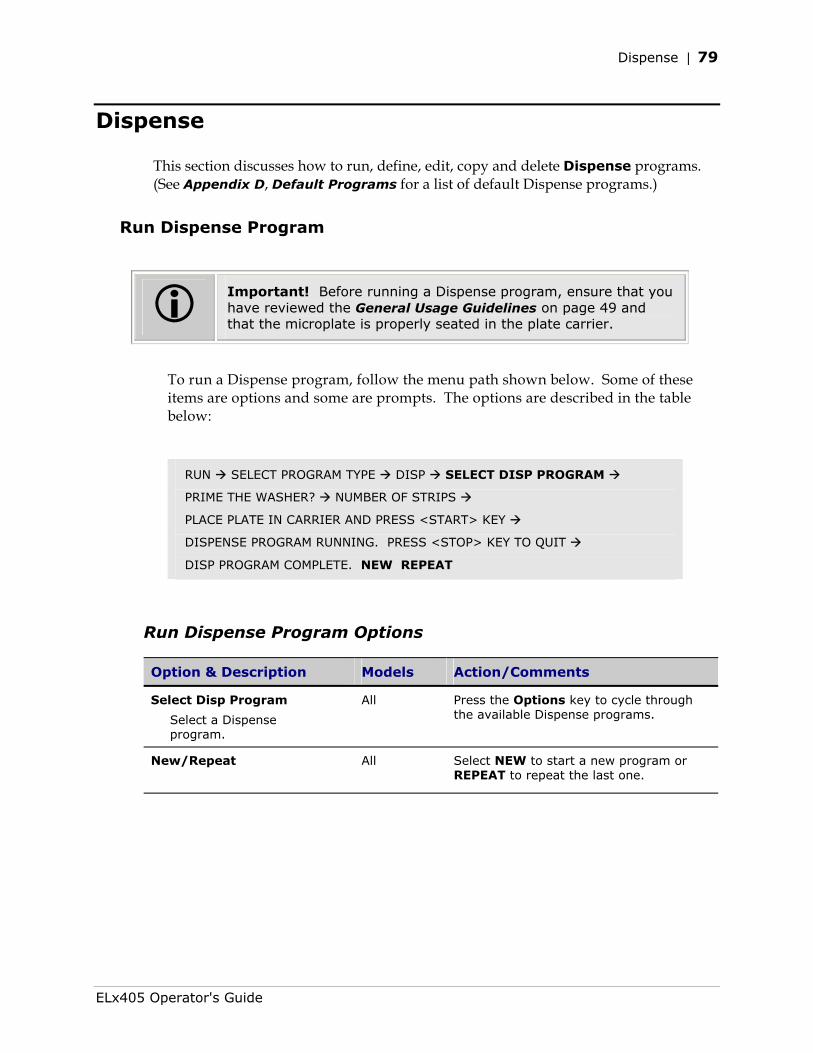
Dispense | 79
Dispense
This section discusses how to run, define, edit, copy and delete Dispense programs. (See Appendix D, Default Programs for a list of default Dispense programs.)
Run Dispense Program
Important! Before running a Dispense program, ensure that you have reviewed the General Usage Guidelines on page 49 and that the microplate is properly seated in the plate carrier.
To run a Dispense program, follow the menu path shown below. Some of these items are options and some are prompts. The options are described in the table below:
RUN SELECT PROGRAM TYPE DISP SELECT DISP PROGRAM
PRIME THE WASHER? NUMBER OF STRIPS
PLACE PLATE IN CARRIER AND PRESS <START> KEY
DISPENSE PROGRAM RUNNING. PRESS <STOP> KEY TO QUIT
DISP PROGRAM COMPLETE. NEW REPEAT
Run Dispense Program Options
Option & Description Models Action/Comments
Select Disp Program
Select a Dispense program.
All
Press the Options key to cycle through the available Dispense programs.
New/Repeat
All Select NEW to start a new program or REPEAT to repeat the last one.
ELx405 Operator's Guide
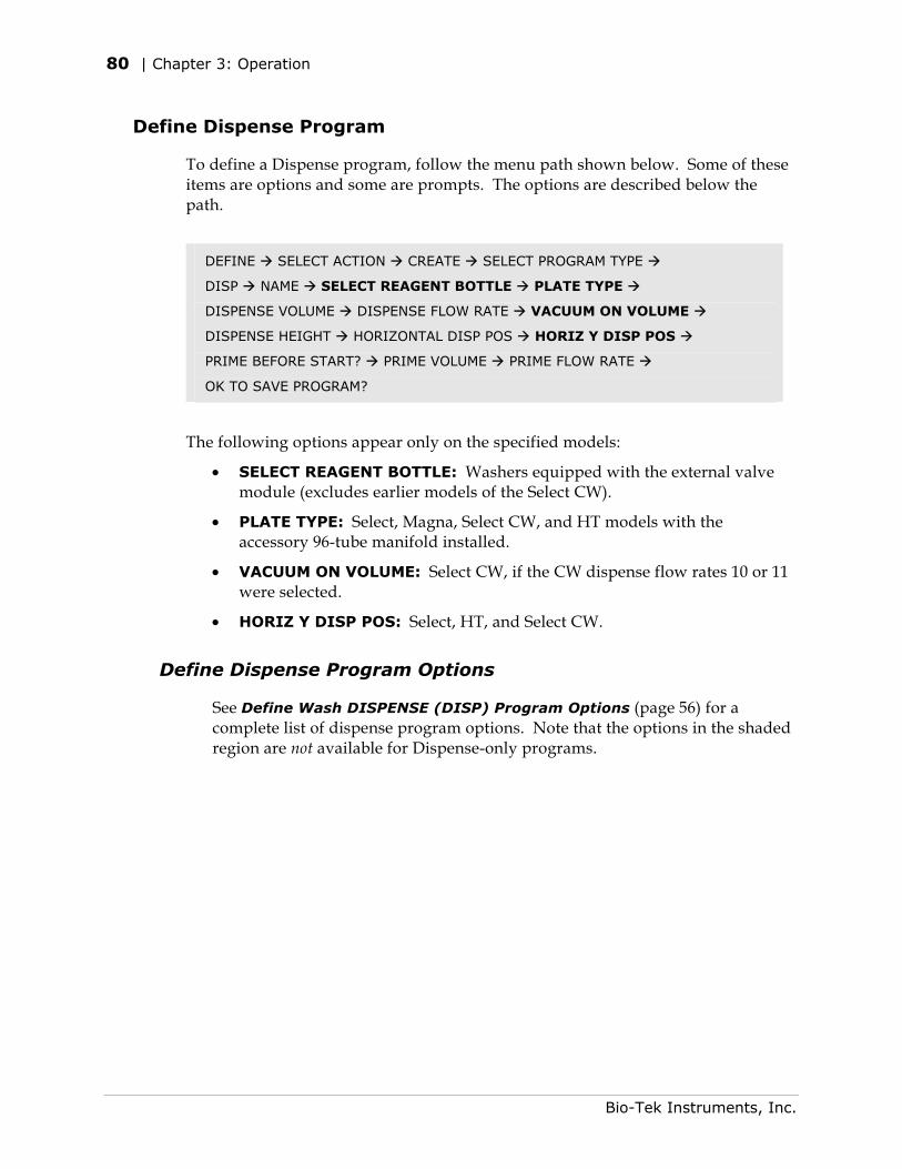
80 | Chapter 3: Operation
Define Dispense Program
To define a Dispense program, follow the menu path shown below. Some of these items are options and some are prompts. The options are described below the path.
DEFINE SELECT ACTION CREATE SELECT PROGRAM TYPE
DISP NAME SELECT REAGENT BOTTLE PLATE TYPE
DISPENSE VOLUME DISPENSE FLOW RATE VACUUM ON VOLUME
DISPENSE HEIGHT HORIZONTAL DISP POS HORIZ Y DISP POS
PRIME BEFORE START? PRIME VOLUME PRIME FLOW RATE
OK TO SAVE PROGRAM?
The following options appear only on the specified models:
• SELECT REAGENT BOTTLE: Washers equipped with the external valve module (excludes earlier models of the Select CW).
• PLATE TYPE: Select, Magna, Select CW, and HT models with the accessory 96-tube manifold installed.
• VACUUM ON VOLUME: Select CW, if the CW dispense flow rates 10 or 11 were selected.
• HORIZ Y DISP POS: Select, HT, and Select CW.
Define Dispense Program Options
See Define Wash DISPENSE (DISP) Program Options (page 56) for a complete list of dispense program options. Note that the options in the shaded region are not available for Dispense-only programs.
Bio-Tek Instruments, Inc.
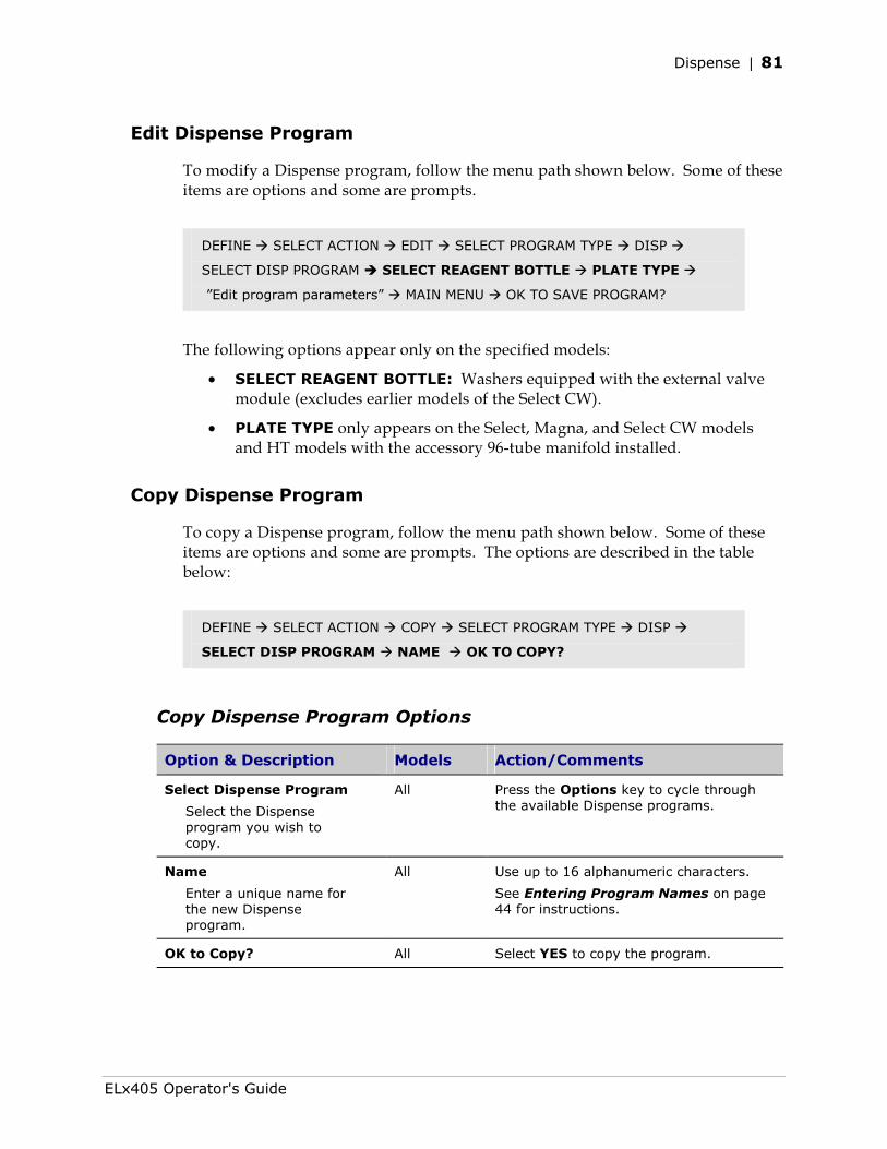
Dispense | 81
Edit Dispense Program
To modify a Dispense program, follow the menu path shown below. Some of these items are options and some are prompts.
DEFINE SELECT ACTION EDIT SELECT PROGRAM TYPE DISP
SELECT DISP PROGRAM SELECT REAGENT BOTTLE PLATE TYPE
”Edit program parameters” MAIN MENU OK TO SAVE PROGRAM?
The following options appear only on the specified models:
• SELECT REAGENT BOTTLE: Washers equipped with the external valve module (excludes earlier models of the Select CW).
• PLATE TYPE only appears on the Select, Magna, and Select CW models and HT models with the accessory 96-tube manifold installed.
Copy Dispense Program
To copy a Dispense program, follow the menu path shown below. Some of these items are options and some are prompts. The options are described in the table below:
DEFINE SELECT ACTION COPY SELECT PROGRAM TYPE DISP
SELECT DISP PROGRAM NAME OK TO COPY?
Copy Dispense Program Options
Option & Description Models Action/Comments
Select Dispense Program
Select the Dispense program you wish to copy.
All Press the Options key to cycle through the available Dispense programs.
Name
Enter a unique name for the new Dispense program.
All Use up to 16 alphanumeric characters.
See Entering Program Names on page 44 for instructions.
OK to Copy? All Select YES to copy the program.
ELx405 Operator's Guide
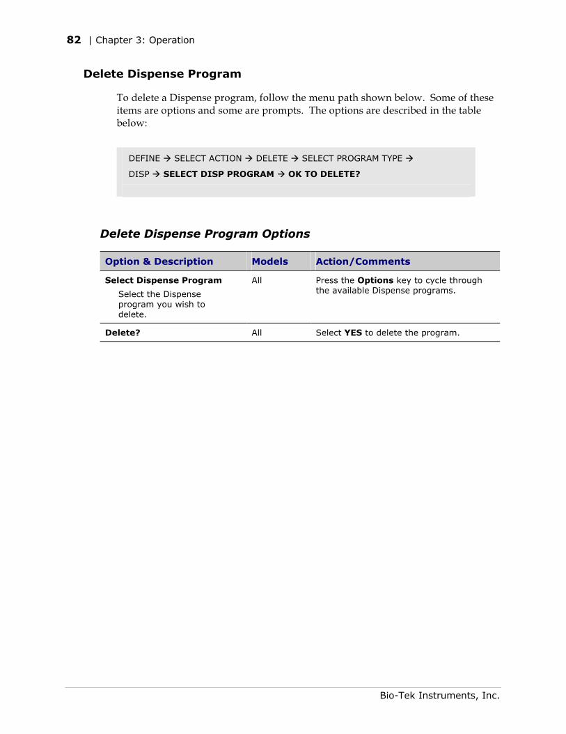
82 | Chapter 3: Operation
Delete Dispense Program
To delete a Dispense program, follow the menu path shown below. Some of these items are options and some are prompts. The options are described in the table below:
DEFINE SELECT ACTION DELETE SELECT PROGRAM TYPE
DISP SELECT DISP PROGRAM OK TO DELETE?
Delete Dispense Program Options
Option & Description Models Action/Comments
Select Dispense Program
Select the Dispense program you wish to delete.
All Press the Options key to cycle through the available Dispense programs.
Delete? All Select YES to delete the program.
Bio-Tek Instruments, Inc.
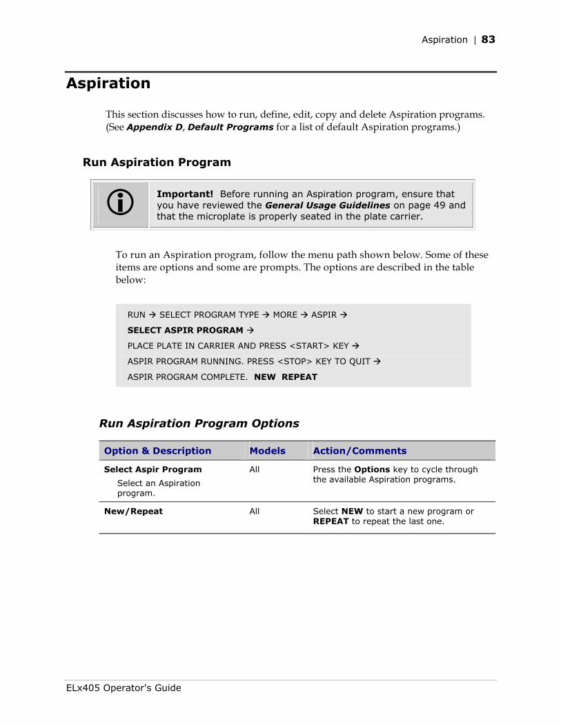
Aspiration | 83
Aspiration
This section discusses how to run, define, edit, copy and delete Aspiration programs. (See Appendix D, Default Programs for a list of default Aspiration programs.)
Run Aspiration Program
Important! Before running an Aspiration program, ensure that you have reviewed the General Usage Guidelines on page 49 and that the microplate is properly seated in the plate carrier.
To run an Aspiration program, follow the menu path shown below. Some of these items are options and some are prompts. The options are described in the table below:
RUN SELECT PROGRAM TYPE MORE ASPIR
SELECT ASPIR PROGRAM
PLACE PLATE IN CARRIER AND PRESS <START> KEY
ASPIR PROGRAM RUNNING. PRESS <STOP> KEY TO QUIT
ASPIR PROGRAM COMPLETE. NEW REPEAT
Run Aspiration Program Options
Option & Description Models Action/Comments
Select Aspir Program
Select an Aspiration program.
All Press the Options key to cycle through the available Aspiration programs.
New/Repeat
All Select NEW to start a new program or REPEAT to repeat the last one.
ELx405 Operator's Guide
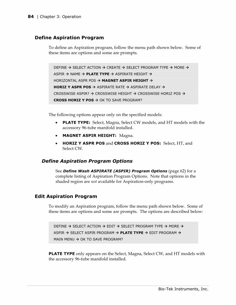
84 | Chapter 3: Operation
Define Aspiration Program
To define an Aspiration program, follow the menu path shown below. Some of these items are options and some are prompts.
DEFINE SELECT ACTION CREATE SELECT PROGRAM TYPE MORE
ASPIR NAME PLATE TYPE ASPIRATE HEIGHT
HORIZONTAL ASPR POS MAGNET ASPIR HEIGHT
HORIZ Y ASPR POS ASPIRATE RATE ASPIRATE DELAY
CROSSWISE ASPIR? CROSSWISE HEIGHT CROSSWISE HORIZ POS
CROSS HORIZ Y POS OK TO SAVE PROGRAM?
The following options appear only on the specified models:
• PLATE TYPE: Select, Magna, Select CW models, and HT models with the accessory 96-tube manifold installed.
• MAGNET ASPIR HEIGHT: Magna.
• HORIZ Y ASPR POS and CROSS HORIZ Y POS: Select, HT, and Select CW.
Define Aspiration Program Options
See Define Wash ASPIRATE (ASPIR) Program Options (page 62) for a complete listing of Aspiration Program Options. Note that options in the shaded region are not available for Aspiration-only programs.
Edit Aspiration Program
To modify an Aspiration program, follow the menu path shown below. Some of these items are options and some are prompts. The options are described below:
DEFINE SELECT ACTION EDIT SELECT PROGRAM TYPE MORE
ASPIR SELECT ASPIR PROGRAM PLATE TYPE EDIT PROGRAM
MAIN MENU OK TO SAVE PROGRAM?
PLATE TYPE only appears on the Select, Magna, Select CW, and HT models with the accessory 96-tube manifold installed.
Bio-Tek Instruments, Inc.
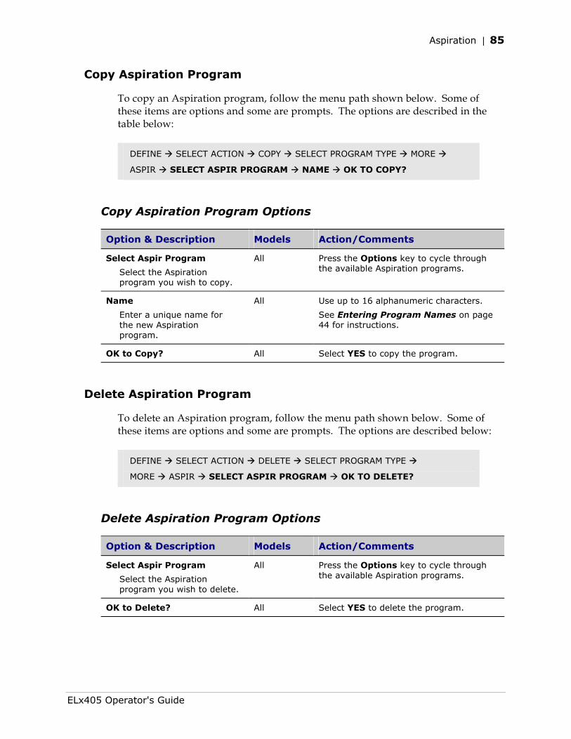
Aspiration | 85
Copy Aspiration Program
To copy an Aspiration program, follow the menu path shown below. Some of these items are options and some are prompts. The options are described in the table below:
DEFINE SELECT ACTION COPY SELECT PROGRAM TYPE MORE
ASPIR SELECT ASPIR PROGRAM NAME OK TO COPY?
Copy Aspiration Program Options
Option & Description Models Action/Comments
Select Aspir Program
Select the Aspiration program you wish to copy.
All Press the Options key to cycle through the available Aspiration programs.
Name
Enter a unique name for the new Aspiration program.
All Use up to 16 alphanumeric characters.
See Entering Program Names on page 44 for instructions.
OK to Copy? All Select YES to copy the program.
Delete Aspiration Program
To delete an Aspiration program, follow the menu path shown below. Some of these items are options and some are prompts. The options are described below:
DEFINE SELECT ACTION DELETE SELECT PROGRAM TYPE
MORE ASPIR SELECT ASPIR PROGRAM OK TO DELETE?
Delete Aspiration Program Options
Option & Description Models Action/Comments
Select Aspir Program
Select the Aspiration program you wish to delete.
All Press the Options key to cycle through the available Aspiration programs.
OK to Delete? All Select YES to delete the program.
ELx405 Operator's Guide
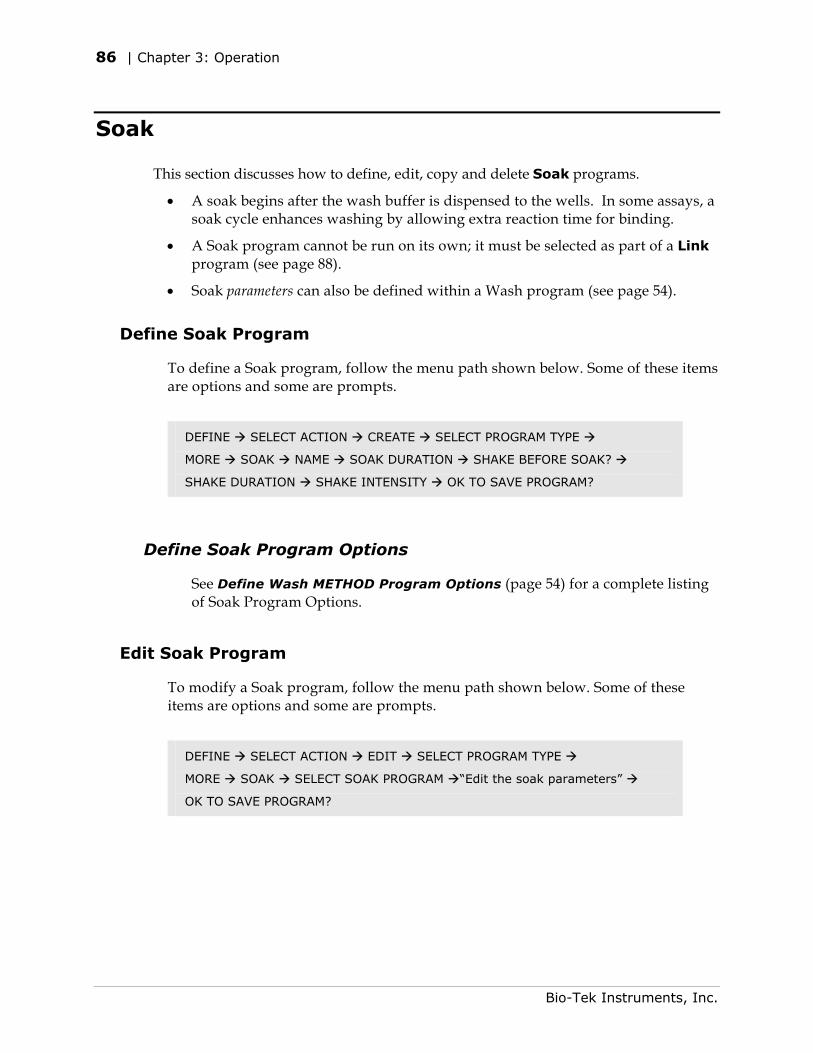
86 | Chapter 3: Operation
Soak
This section discusses how to define, edit, copy and delete Soak programs.
• A soak begins after the wash buffer is dispensed to the wells. In some assays, a soak cycle enhances washing by allowing extra reaction time for binding.
• A Soak program cannot be run on its own; it must be selected as part of a Link program (see page 88).
• Soak parameters can also be defined within a Wash program (see page 54).
Define Soak Program
To define a Soak program, follow the menu path shown below. Some of these items are options and some are prompts.
DEFINE SELECT ACTION CREATE SELECT PROGRAM TYPE
MORE SOAK NAME SOAK DURATION SHAKE BEFORE SOAK?
SHAKE DURATION SHAKE INTENSITY OK TO SAVE PROGRAM?
Define Soak Program Options
See Define Wash METHOD Program Options (page 54) for a complete listing of Soak Program Options.
Edit Soak Program
To modify a Soak program, follow the menu path shown below. Some of these items are options and some are prompts.
DEFINE SELECT ACTION EDIT SELECT PROGRAM TYPE
MORE SOAK SELECT SOAK PROGRAM “Edit the soak parameters”
OK TO SAVE PROGRAM?
Bio-Tek Instruments, Inc.
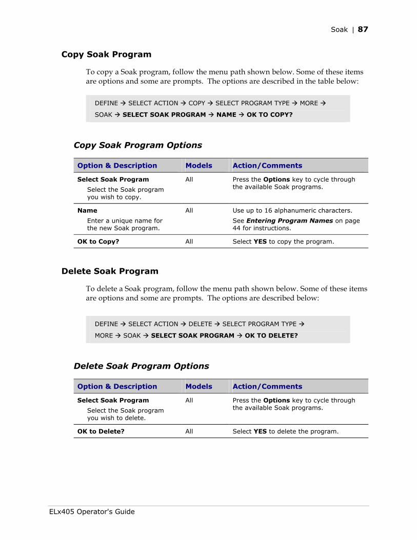
Soak | 87
Copy Soak Program
To copy a Soak program, follow the menu path shown below. Some of these items are options and some are prompts. The options are described in the table below:
DEFINE SELECT ACTION COPY SELECT PROGRAM TYPE MORE
SOAK SELECT SOAK PROGRAM NAME OK TO COPY?
Copy Soak Program Options
Option & Description Models Action/Comments
Select Soak Program
Select the Soak program you wish to copy.
All Press the Options key to cycle through the available Soak programs.
Name
Enter a unique name for the new Soak program.
All Use up to 16 alphanumeric characters.
See Entering Program Names on page 44 for instructions.
OK to Copy? All Select YES to copy the program.
Delete Soak Program
To delete a Soak program, follow the menu path shown below. Some of these items are options and some are prompts. The options are described below:
DEFINE SELECT ACTION DELETE SELECT PROGRAM TYPE
MORE SOAK SELECT SOAK PROGRAM OK TO DELETE?
Delete Soak Program Options
Option & Description Models Action/Comments
Select Soak Program
Select the Soak program you wish to delete.
All Press the Options key to cycle through the available Soak programs.
OK to Delete? All Select YES to delete the program.
ELx405 Operator's Guide
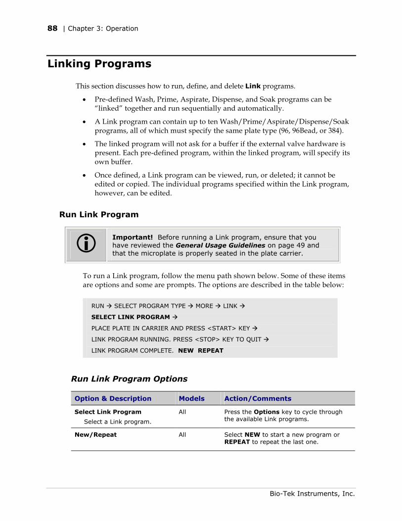
88 | Chapter 3: Operation
Linking Programs
This section discusses how to run, define, and delete Link programs.
• Pre-defined Wash, Prime, Aspirate, Dispense, and Soak programs can be “linked” together and run sequentially and automatically.
• A Link program can contain up to ten Wash/Prime/Aspirate/Dispense/Soak programs, all of which must specify the same plate type (96, 96Bead, or 384).
• The linked program will not ask for a buffer if the external valve hardware is present. Each pre-defined program, within the linked program, will specify its own buffer.
• Once defined, a Link program can be viewed, run, or deleted; it cannot be edited or copied. The individual programs specified within the Link program, however, can be edited.
Run Link Program
Important! Before running a Link program, ensure that you have reviewed the General Usage Guidelines on page 49 and that the microplate is properly seated in the plate carrier.
To run a Link program, follow the menu path shown below. Some of these items are options and some are prompts. The options are described in the table below:
RUN SELECT PROGRAM TYPE MORE LINK
SELECT LINK PROGRAM
PLACE PLATE IN CARRIER AND PRESS <START> KEY
LINK PROGRAM RUNNING. PRESS <STOP> KEY TO QUIT
LINK PROGRAM COMPLETE. NEW REPEAT
Run Link Program Options
Option & Description Models Action/Comments
Select Link Program
Select a Link program.
All Press the Options key to cycle through the available Link programs.
New/Repeat
All Select NEW to start a new program or REPEAT to repeat the last one.
Bio-Tek Instruments, Inc.
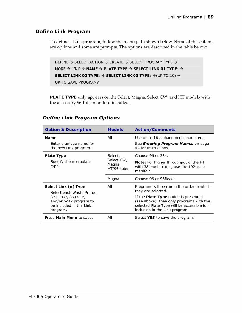
Linking Programs | 89
Define Link Program
To define a Link program, follow the menu path shown below. Some of these items are options and some are prompts. The options are described in the table below:
DEFINE SELECT ACTION CREATE SELECT PROGRAM TYPE
MORE LINK NAME PLATE TYPE SELECT LINK 01 TYPE:
SELECT LINK 02 TYPE: SELECT LINK 03 TYPE: (UP TO 10)
OK TO SAVE PROGRAM?
PLATE TYPE only appears on the Select, Magna, Select CW, and HT models with the accessory 96-tube manifold installed.
Define Link Program Options
Option & Description Models Action/Comments
Name
Enter a unique name for the new Link program.
All Use up to 16 alphanumeric characters.
See Entering Program Names on page 44 for instructions.
Select, Select CW, Magna, HT/96-tube
Choose 96 or 384.
Note: For higher throughput of the HT with 384-well plates, use the 192-tube manifold.
Plate Type
Specify the microplate type.
Magna Choose 96 or 96Bead.
Select Link (n) Type
Select each Wash, Prime, Dispense, Aspirate, and/or Soak program to be included in the Link program.
All Programs will be run in the order in which they are selected.
If the Plate Type option is presented (see above), then only programs with the selected Plate Type will be accessible for inclusion in the Link program.
Press Main Menu to save. All Select YES to save the program.
ELx405 Operator's Guide
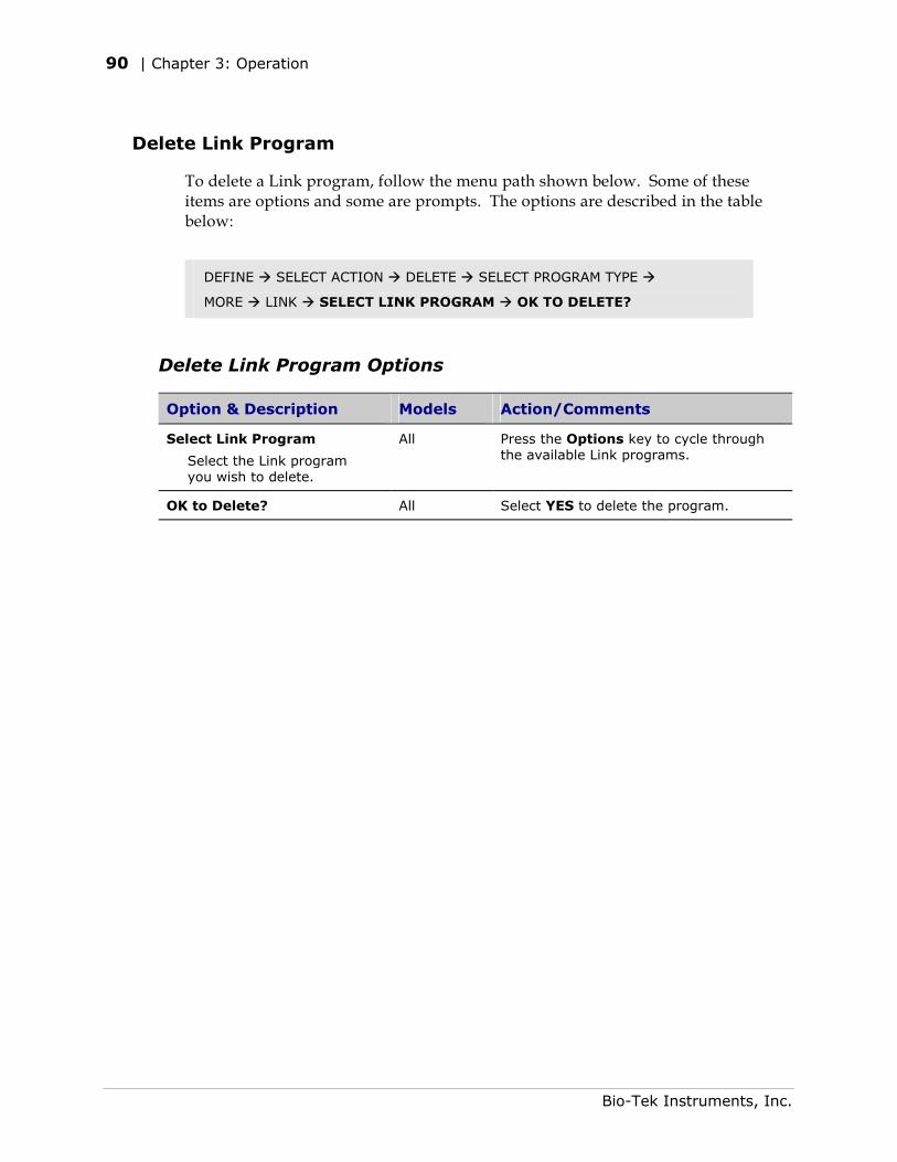
90 | Chapter 3: Operation
Delete Link Program
To delete a Link program, follow the menu path shown below. Some of these items are options and some are prompts. The options are described in the table below:
DEFINE SELECT ACTION DELETE SELECT PROGRAM TYPE
MORE LINK SELECT LINK PROGRAM OK TO DELETE?
Delete Link Program Options
Option & Description Models Action/Comments
Select Link Program
Select the Link program you wish to delete.
All Press the Options key to cycle through the available Link programs.
OK to Delete? All Select YES to delete the program.
Bio-Tek Instruments, Inc.
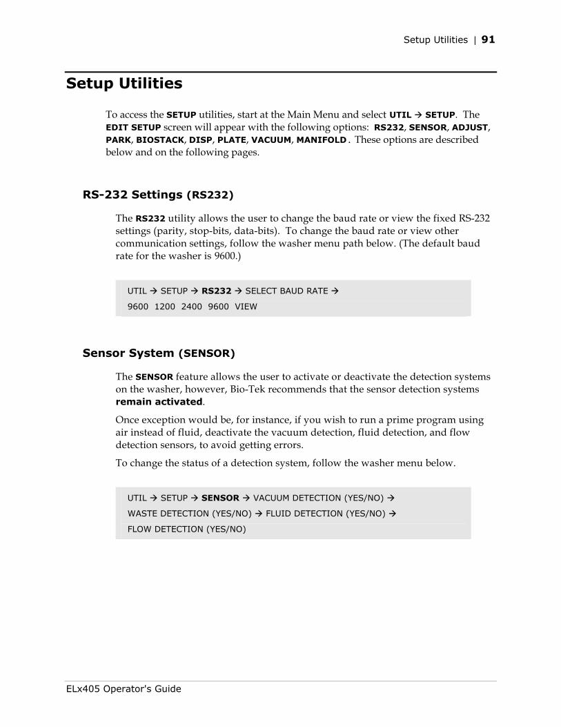
Setup Utilities | 91
Setup Utilities
To access the SETUP utilities, start at the Main Menu and select UTIL SETUP. The EDIT SETUP screen will appear with the following options: RS232, SENSOR, ADJUST, PARK, BIOSTACK, DISP, PLATE, VACUUM, MANIFOLD. These options are described below and on the following pages.
RS-232 Settings (RS232)
The RS232 utility allows the user to change the baud rate or view the fixed RS-232 settings (parity, stop-bits, data-bits). To change the baud rate or view other communication settings, follow the washer menu path below. (The default baud rate for the washer is 9600.)
UTIL SETUP RS232 SELECT BAUD RATE
9600 1200 2400 9600 VIEW
Sensor System (SENSOR)
The SENSOR feature allows the user to activate or deactivate the detection systems on the washer, however, Bio-Tek recommends that the sensor detection systems remain activated.
Once exception would be, for instance, if you wish to run a prime program using air instead of fluid, deactivate the vacuum detection, fluid detection, and flow detection sensors, to avoid getting errors.
To change the status of a detection system, follow the washer menu below.
UTIL SETUP SENSOR VACUUM DETECTION (YES/NO)
WASTE DETECTION (YES/NO) FLUID DETECTION (YES/NO)
FLOW DETECTION (YES/NO)
ELx405 Operator's Guide
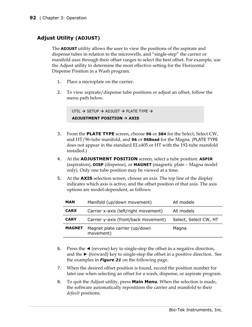
92 | Chapter 3: Operation
Adjust Utility (ADJUST)
The ADJUST utility allows the user to view the positions of the aspirate and dispense tubes in relation to the microwells, and “single-step” the carrier or manifold axes through their offset ranges to select the best offset. For example, use the Adjust utility to determine the most effective setting for the Horizontal Dispense Position in a Wash program.
1. Place a microplate on the carrier.
2. To view aspirate/dispense tube positions or adjust an offset, follow the menu path below.
UTIL SETUP ADJUST PLATE TYPE
ADJUSTMENT POSITION AXIS
3. From the PLATE TYPE screen, choose 96 or 384 for the Select, Select CW, and HT/96-tube manifold, and 96 or 96Bead for the Magna. (PLATE TYPE does not appear in the standard ELx405 or HT with the 192-tube manifold installed.)
4. At the ADJUSTMENT POSITION screen, select a tube position: ASPIR (aspiration), DISP (dispense), or MAGNET (magnetic plate – Magna model only). Only one tube position may be viewed at a time.
5. At the AXIS selection screen, choose an axis. The top line of the display indicates which axis is active, and the offset position of that axis. The axis options are model-dependent, as follows:
MAN Manifold (up/down movement) All models
CARX Carrier x-axis (left/right movement) All models
CARY Carrier y-axis (front/back movement) Select, Select CW, HT
MAGNET Magnet plate carrier (up/down movement)
Magna
6. Press the ◄ (reverse) key to single-step the offset in a negative direction, and the ► (forward) key to single-step the offset in a positive direction. See the examples in Figure 21 on the following page.
7. When the desired offset position is found, record the position number for later use when selecting an offset for a wash, dispense, or aspirate program.
8. To quit the Adjust utility, press Main Menu. When the selection is made, the software automatically repositions the carrier and manifold to their default positions.
Bio-Tek Instruments, Inc.
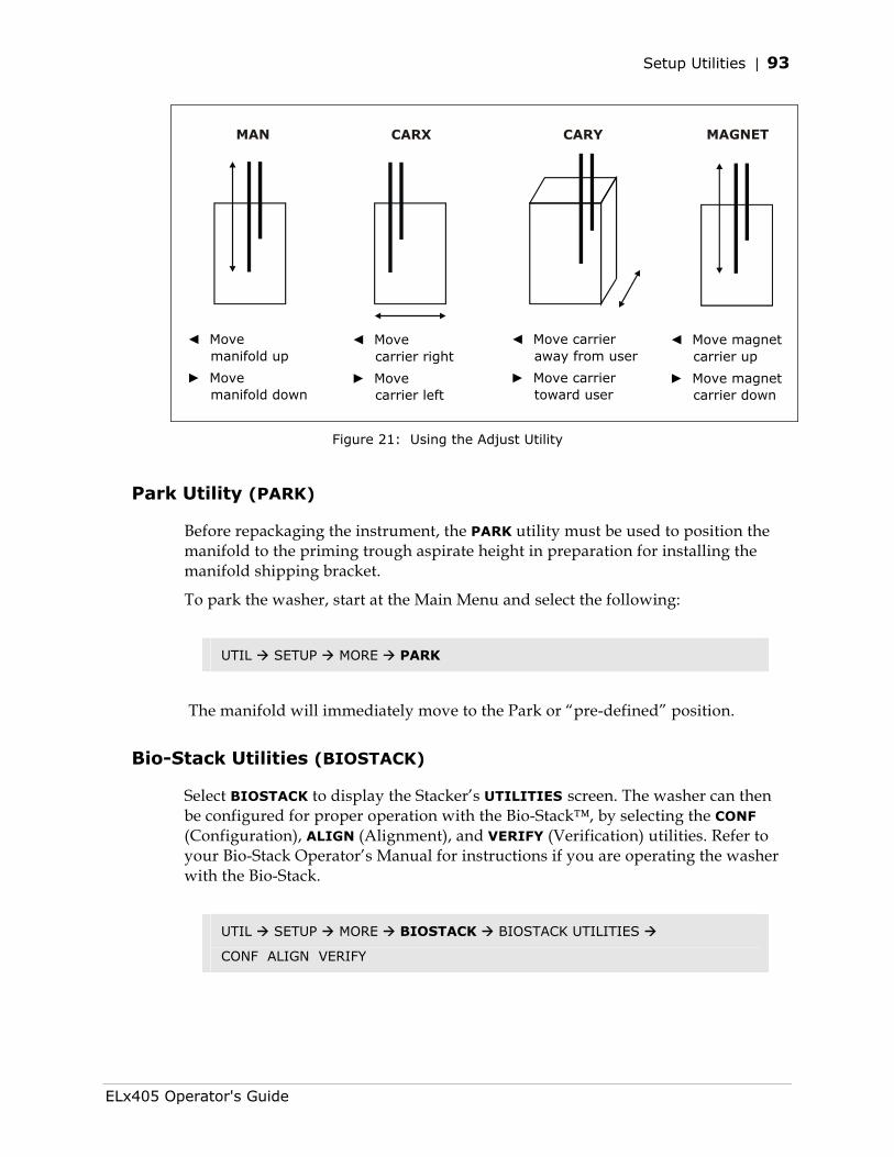
Setup Utilities | 93
MAN MAGNET CARX CARY
◄ Move manifold up
► Move manifold down
◄ Move carrier away from user
► Move carrier toward user
◄ Move carrier right
► Move carrier left
◄ Move magnet carrier up
► Move magnet carrier down
Figure 21: Using the Adjust Utility
Park Utility (PARK)
Before repackaging the instrument, the PARK utility must be used to position the manifold to the priming trough aspirate height in preparation for installing the manifold shipping bracket.
To park the washer, start at the Main Menu and select the following:
UTIL SETUP MORE PARK
The manifold will immediately move to the Park or “pre-defined” position.
Bio-Stack Utilities (BIOSTACK)
Select BIOSTACK to display the Stacker’s UTILITIES screen. The washer can then be configured for proper operation with the Bio-Stack™, by selecting the CONF (Configuration), ALIGN (Alignment), and VERIFY (Verification) utilities. Refer to your Bio-Stack Operator’s Manual for instructions if you are operating the washer with the Bio-Stack.
UTIL SETUP MORE BIOSTACK BIOSTACK UTILITIES
CONF ALIGN VERIFY
ELx405 Operator's Guide
94 | Chapter 3: Operation
Delay After Dispense (DISP)
A Delay After Dispense feature enables you to change the value for the delay period between dispensing and aspirating in Wash programs. The delay range is 0 to 2000 msec, with a default value of 1000 msec.
To change the delay period, select the following:
UTIL SETUP MORE MORE DISP DELAY AFTER DISP
Plate Clearance Height (PLATE)
A Plate Clearance Height option has been added to accommodate plates that are slightly taller than standard plates to ensure that the manifold tubes are raised high enough above the plate to prevent crashes when the plate carrier moves. The clearance height range is 12 (3.048 mm) to 180 (22.86 mm), with a default value of 130 (16.510 mm). Due to hardware variations, however, the 180 value may be out of range for some washers; it is recommended, therefore, that the highest value be closer to 175.
To change the plate clearance height, select the following:
UTIL SETUP MORE MORE PLATE PLATE CLEAR HEIGHT
Vacuum Dissipation Delay (VACUUM)
The Vacuum Dissipation Delay feature enables you to change the value for vacuum dissipation delay at the completion of a program. The delay range is 1 to 50 sec with a default value of 5 sec.
Increasing the delay prevents some vacuum systems, such as the High Flow Pump, from drawing excess current and blowing the auxiliary 5-amp fuse (PN 46055). A delay of 10 seconds or greater is recommended when using the High Flow pump with 10-liter bottles; a delay of at least 20 seconds is recommended when using the High Flow Pump with 20-liter bottles.
To change the vacuum dissipation delay, select the following:
UTIL SETUP MORE MORE VACUUM VAC DISSIPATE DELAY
Note: The Delay After Dispense and Vacuum Dissipation Delay features allow for overall faster plate processing, which may be useful for high-throughput microplate washing, for example, when the washer is used in conjunction with the Bio-Stack or other automated system. For standalone use, Bio-Tek does not recommend changing these parameters from the default setting, unless you are increasing the vacuum dissipation delay for the High Flow vacuum pump. If this is the case, please contact TAC if you need assistance with changing the these parameters.
Bio-Tek Instruments, Inc.
Setup Utilities | 95
Manifold Selection (MANIFOLD)
Some washer models can support two types of manifolds:
• The HT2/HTV2 supports the dual 192-tube manifold and the dual 96-tube manifold.
• The Select can be upgraded to an HT, in which case it can support the dual 192-tube manifold and the dual 96-tube manifold.
When a manifold is installed at the factory, a parameter is set on the washer to indicate which manifold type is installed. This parameter is called “Manifold Selection” and it can be set to 96 or 192.
For the models described above, this parameter must be changed each time the manifold is changed. For example, the HT2/HTV2 is shipped with the 192-tube manifold installed and the 96-tube packaged as an accessory. If the 192-tube manifold is removed and the 96-tube installed, the manifold selection parameter must be changed from 192 to 96. See Appendix E, Changing the Manifolds for complete instructions.
To view or change the Manifold Selection parameter, select the following:
UTIL SETUP MORE MORE MORE MANIFOLD
MANIFOLD SELECTION 96 or 192
ELx405 Operator's Guide

96 | Chapter 3: Operation
ELx405 Washer Menu Maps Refer to the Washer Menu Maps on pages 97 through 100 for a complete listing of options available through the Main Menu.
Bio-Tek Instruments, Inc.
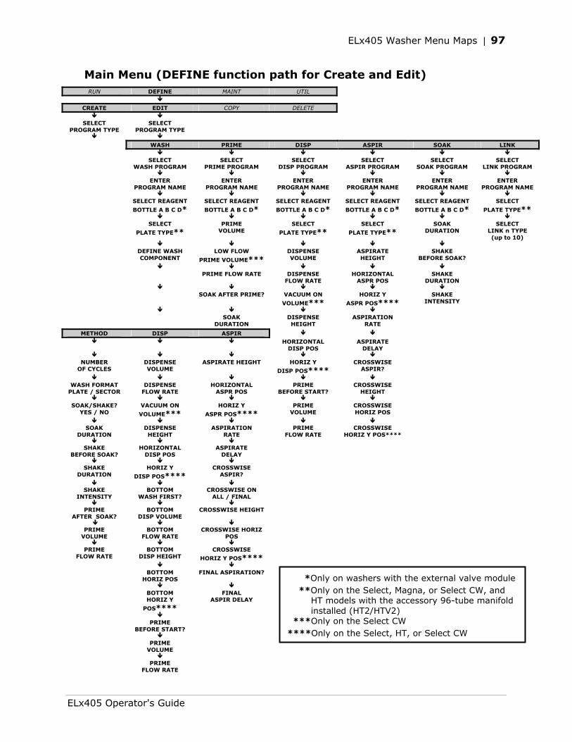
ELx405 Washer Menu Maps | 97
Main Menu (DEFINE function path for Create and Edit) RUN DEFINE MAINT UTIL
CREATE EDIT COPY DELETE
SELECT
PROGRAM TYPE SELECT
PROGRAM TYPE
WASH PRIME DISP ASPIR SOAK LINK SELECT
WASH PROGRAM SELECT
PRIME PROGRAM SELECT
DISP PROGRAM SELECT
ASPIR PROGRAM SELECT
SOAK PROGRAM SELECT
LINK PROGRAM ENTER
PROGRAM NAME ENTER
PROGRAM NAME ENTER
PROGRAM NAME ENTER
PROGRAM NAME ENTER
PROGRAM NAME ENTER
PROGRAM NAME SELECT REAGENT
BOTTLE A B C D*
SELECT REAGENT
BOTTLE A B C D*
SELECT REAGENT
BOTTLE A B C D*
SELECT REAGENT
BOTTLE A B C D*
SELECT REAGENT
BOTTLE A B C D*
SELECT
PLATE TYPE** SELECT
PLATE TYPE**
PRIME VOLUME
SELECT
PLATE TYPE**
SELECT
PLATE TYPE**
SOAK DURATION
SELECT LINK n TYPE (up to 10)
DEFINE WASH
COMPONENT LOW FLOW
PRIME VOLUME***
DISPENSE VOLUME
ASPIRATE HEIGHT
SHAKE BEFORE SOAK?
PRIME FLOW RATE DISPENSE
FLOW RATE HORIZONTAL
ASPR POS SHAKE
DURATION
SOAK AFTER PRIME? VACUUM ON
VOLUME***
HORIZ Y
ASPR POS****
SHAKE INTENSITY
SOAK
DURATION DISPENSE HEIGHT
ASPIRATION RATE
METHOD DISP ASPIR HORIZONTAL
DISP POS ASPIRATE
DELAY
NUMBER
OF CYCLES DISPENSE VOLUME
ASPIRATE HEIGHT HORIZ Y
DISP POS****
CROSSWISE ASPIR?
WASH FORMAT
PLATE / SECTOR DISPENSE
FLOW RATE HORIZONTAL
ASPR POS PRIME
BEFORE START? CROSSWISE
HEIGHT
SOAK/SHAKE?
YES / NO VACUUM ON
VOLUME***
HORIZ Y
ASPR POS****
PRIME VOLUME
CROSSWISE HORIZ POS
SOAK
DURATION DISPENSE HEIGHT
ASPIRATION RATE
PRIME FLOW RATE
CROSSWISE HORIZ Y POS****
SHAKE
BEFORE SOAK? HORIZONTAL
DISP POS ASPIRATE
DELAY
SHAKE DURATION
HORIZ Y
DISP POS****
CROSSWISE ASPIR?
SHAKE
INTENSITY BOTTOM
WASH FIRST? CROSSWISE ON
ALL / FINAL
PRIME AFTER SOAK?
BOTTOM DISP VOLUME
CROSSWISE HEIGHT
PRIME
VOLUME BOTTOM
FLOW RATE CROSSWISE HORIZ
POS
PRIME FLOW RATE
BOTTOM DISP HEIGHT
CROSSWISE
HORIZ Y POS**** BOTTOM
HORIZ POS FINAL ASPIRATION?
BOTTOM
HORIZ Y
POS****
FINAL ASPIR DELAY
PRIME
BEFORE START?
PRIME
VOLUME
PRIME
FLOW RATE
*Only on washers with the external valve module **Only on the Select, Magna, or Select CW, and HT models with the accessory 96-tube manifold installed (HT2/HTV2) ***Only on the Select CW ****Only on the Select, HT, or Select CW
ELx405 Operator's Guide
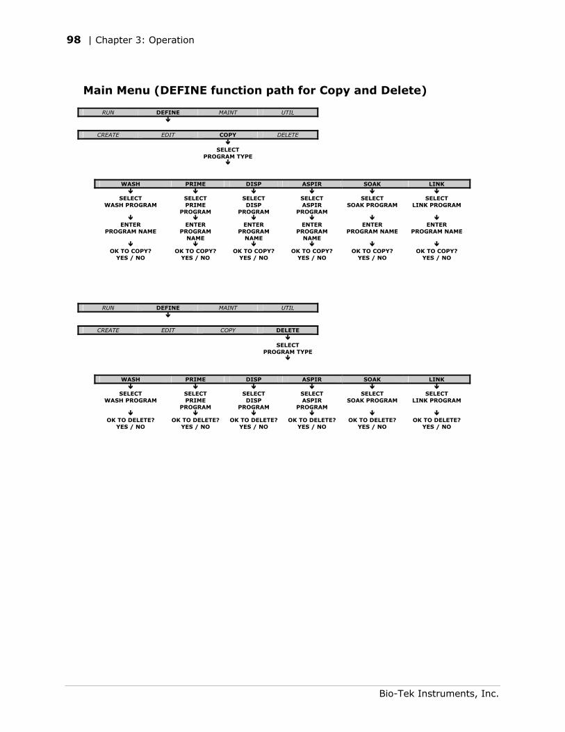
98 | Chapter 3: Operation
Main Menu (DEFINE function path for Copy and Delete)
RUN DEFINE MAINT UTIL
CREATE EDIT COPY DELETE SELECT
PROGRAM TYPE
WASH PRIME DISP ASPIR SOAK LINK
SELECT
WASH PROGRAM SELECT PRIME
PROGRAM
SELECT DISP
PROGRAM
SELECT ASPIR
PROGRAM
SELECT SOAK PROGRAM
SELECT LINK PROGRAM
ENTER
PROGRAM NAME ENTER
PROGRAM NAME
ENTER PROGRAM
NAME
ENTER PROGRAM
NAME
ENTER PROGRAM NAME
ENTER PROGRAM NAME
OK TO COPY?
YES / NO OK TO COPY?
YES / NO OK TO COPY?
YES / NO OK TO COPY?
YES / NO OK TO COPY?
YES / NO OK TO COPY?
YES / NO
RUN DEFINE MAINT UTIL
CREATE EDIT COPY DELETE SELECT
PROGRAM TYPE
WASH PRIME DISP ASPIR SOAK LINK
SELECT
WASH PROGRAM SELECT PRIME
PROGRAM
SELECT ASPIR
PROGRAM
SELECT SOAK PROGRAM
SELECT LINK PROGRAM
OK TO DELETE?
YES / NO OK TO DELETE?
YES / NO OK TO DELETE?
YES / NO OK TO DELETE?
YES / NO OK TO DELETE?
YES / NO OK TO DELETE?
YES / NO
SELECT DISP
PROGRAM
Bio-Tek Instruments, Inc.
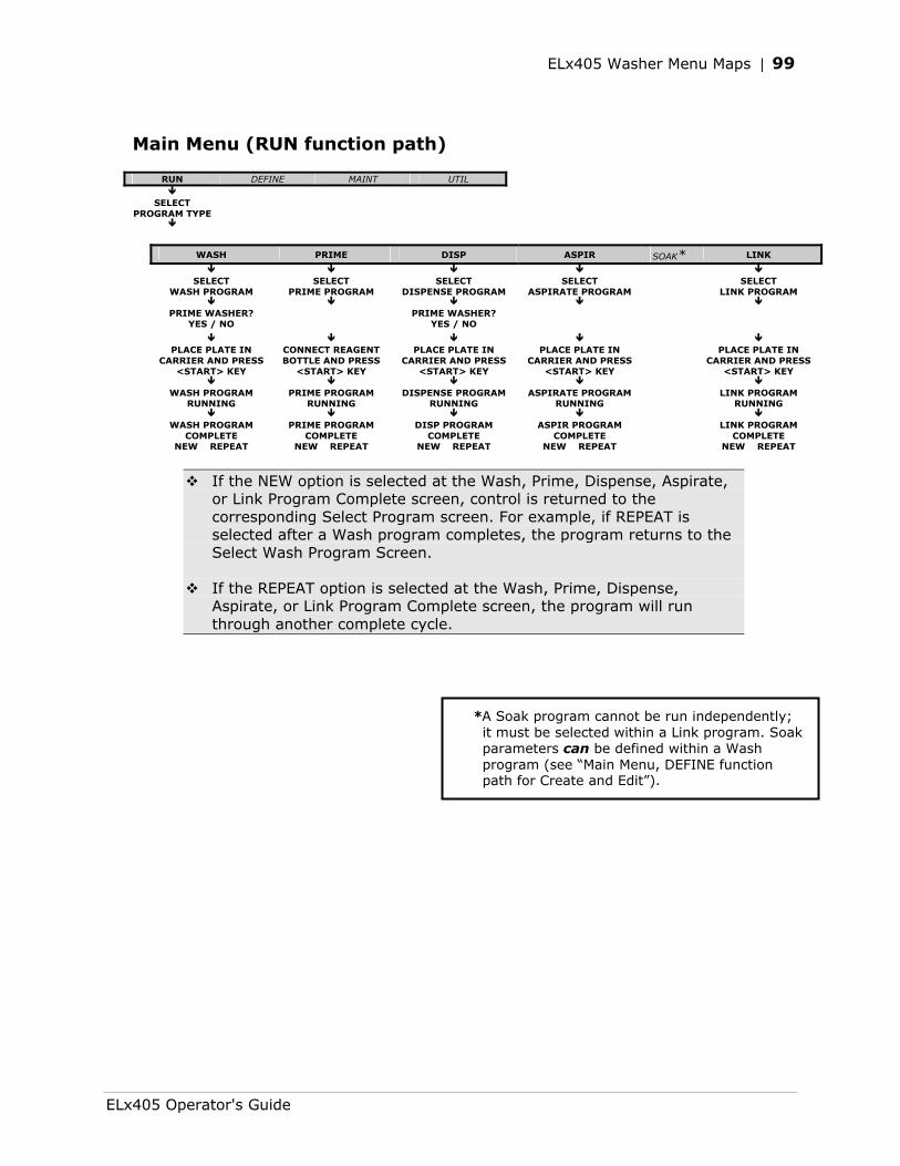
ELx405 Washer Menu Maps | 99
Main Menu (RUN function path)
RUN DEFINE MAINT UTIL
SELECT PROGRAM TYPE
WASH PRIME DISP ASPIR SOAK* LINK
SELECT
WASH PROGRAM SELECT
PRIME PROGRAM SELECT
DISPENSE PROGRAM SELECT
ASPIRATE PROGRAM SELECT
LINK PROGRAM
PRIME WASHER? YES / NO
PRIME WASHER? YES / NO
PLACE PLATE IN
CARRIER AND PRESS <START> KEY
CONNECT REAGENT BOTTLE AND PRESS
<START> KEY
PLACE PLATE IN CARRIER AND PRESS
<START> KEY
PLACE PLATE IN CARRIER AND PRESS
<START> KEY
PLACE PLATE IN CARRIER AND PRESS
<START> KEY
WASH PROGRAM RUNNING
PRIME PROGRAM RUNNING
DISPENSE PROGRAM RUNNING
ASPIRATE PROGRAM RUNNING
LINK PROGRAM RUNNING
WASH PROGRAM
COMPLETE PRIME PROGRAM
COMPLETE DISP PROGRAM
COMPLETE ASPIR PROGRAM
COMPLETE LINK PROGRAM
COMPLETE NEW REPEAT NEW REPEAT NEW REPEAT NEW REPEAT NEW REPEAT
If the NEW option is selected at the Wash, Prime, Dispense, Aspirate, or Link Program Complete screen, control is returned to the corresponding Select Program screen. For example, if REPEAT is selected after a Wash program completes, the program returns to the Select Wash Program Screen.
If the REPEAT option is selected at the Wash, Prime, Dispense, Aspirate, or Link Program Complete screen, the program will run through another complete cycle.
*A Soak program cannot be run independently; it must be selected within a Link program. Soak parameters can be defined within a Wash program (see “Main Menu, DEFINE function path for Create and Edit”).
ELx405 Operator's Guide
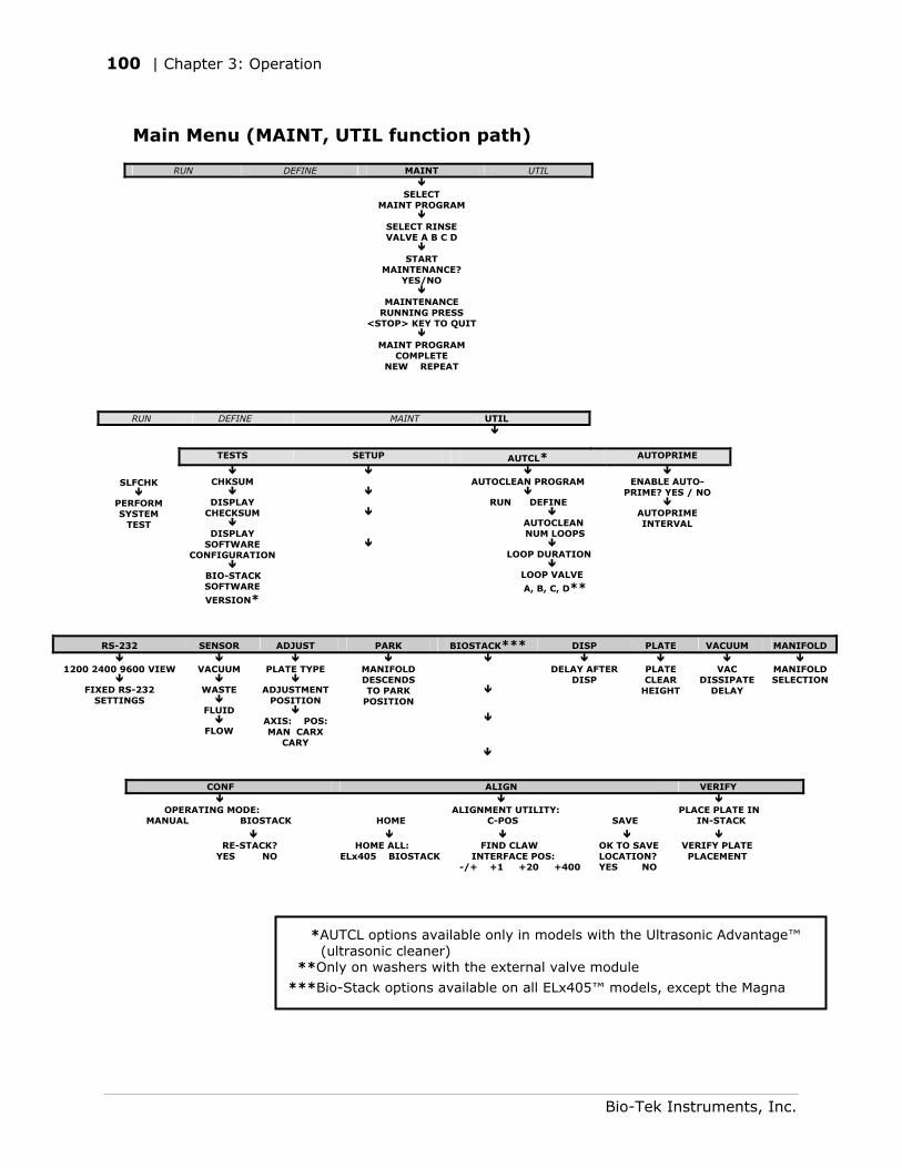
100 | Chapter 3: Operation
Main Menu (MAINT, UTIL function path)
RUN DEFINE MAINT UTIL SELECT
MAINT PROGRAM
SELECT RINSE
VALVE A B C D
START
MAINTENANCE? YES/NO
MAINTENANCE
RUNNING PRESS <STOP> KEY TO QUIT
MAINT PROGRAM
COMPLETE NEW REPEAT
RUN DEFINE MAINT UTIL
TESTS SETUP AUTCL* AUTOPRIME
SLFCHK
PERFORM SYSTEM
TEST
CHKSUM
DISPLAY
CHECKSUM
DISPLAY SOFTWARE
CONFIGURATION
BIO-STACK SOFTWARE
VERSION*
AUTOCLEAN PROGRAM
RUN DEFINE
AUTOCLEAN NUM LOOPS
LOOP DURATION
LOOP VALVE
A, B, C, D**
ENABLE AUTO-
PRIME? YES / NO
AUTOPRIME INTERVAL
RS-232 SENSOR ADJUST PARK BIOSTACK*** DISP PLATE VACUUM MANIFOLD
MANIFOLD SELECTION
1200 2400 9600 VIEW
FIXED RS-232
SETTINGS
VACUUM
WASTE
FLUID
FLOW
PLATE TYPE
ADJUSTMENT
POSITION
AXIS: POS: MAN CARX
CARY
MANIFOLD DESCENDS TO PARK
POSITION
DELAY AFTER
DISP
PLATE CLEAR
HEIGHT
VAC
DISSIPATE DELAY
CONF ALIGN VERIFY OPERATING MODE: MANUAL BIOSTACK
ALIGNMENT UTILITY: HOME C-POS SAVE
PLACE PLATE IN IN-STACK
RE-STACK? YES NO
HOME ALL: ELx405 BIOSTACK
FIND CLAW INTERFACE POS: -/+ +1 +20 +400
OK TO SAVE LOCATION? YES NO
VERIFY PLATE PLACEMENT
*AUTCL options available only in models with the Ultrasonic Advantage™ (ultrasonic cleaner) **Only on washers with the external valve module
***Bio-Stack options available on all ELx405™ models, except the Magna
Bio-Tek Instruments, Inc.
Chapter 4
Preventive Maintenance
This chapter describes how to maintain the washer, prepare it for storage or shipment, and decontaminate the instrument.
Overview................................................................................102 Recommended Maintenance Schedule.........................................103 Required Materials ...................................................................104 Warnings & Precautions ............................................................105 Maintenance Programs .............................................................106 Prime Programs.......................................................................107 Rinse/Soak the Fluid Path .........................................................109 Clean Components...................................................................114 Decontaminate the Washer .......................................................128 Prepare for Storage or Shipment................................................134 Replace Components................................................................136
102 | Chapter 4: Preventive Maintenance
Overview
A Preventive Maintenance (PM) regimen for the ELx405™ includes rinsing and soaking the fluid path and cleaning the washer’s various components.
The chart on the next page summarizes Bio-Tek’s recommended maintenance tasks, and indicates approximately how often each task should be performed. Daily and periodic routines and minimal guidelines for frequency are listed. Beyond that, it is difficult for Bio-Tek to recommend a fixed frequency for each task to be performed. The risk and performance factors of your assays should determine the frequency with which to conduct these tasks.
Therefore, Bio-Tek recommends you develop a maintenance schedule for your washer based on the characteristics of the fluids used and the washer’s activity level. Some questions you should consider are:
• Are the fluids you’re using prone to dry and harden quickly? If yes, the dispense and aspirate tubes can clog quickly, and therefore they must be rinsed frequently and cleaned regularly.
• Is the washer in use continuously, or does it sit idle for several hours or days at a time? If the washer will be sitting idle, the tubes should be soaked to keep them in a “wetted” state. The rinsing procedure (or the AUTOPRIME program) should be performed if the washer is idle for more than 3 hours.
• Is a solution containing surfactant used throughout the day? The wash solutions in use will affect the rinsing frequency. If the solution does not contain surfactant, consider rinsing (or running AUTOPRIME) at least once an hour.
Schedule
The following chart recommends preventive maintenance tasks, the frequency with which each task should be performed, and the pre-defined onboard Maintenance program that should be run (if applicable).
It is important to note that the risk and performance factors associated with your assays may require that some or all of the procedures be performed more frequently than presented in this schedule.
Models with the Ultrasonic Advantage™: The ultrasonic cleaner does not require maintenance.
Bio-Tek Instruments, Inc.
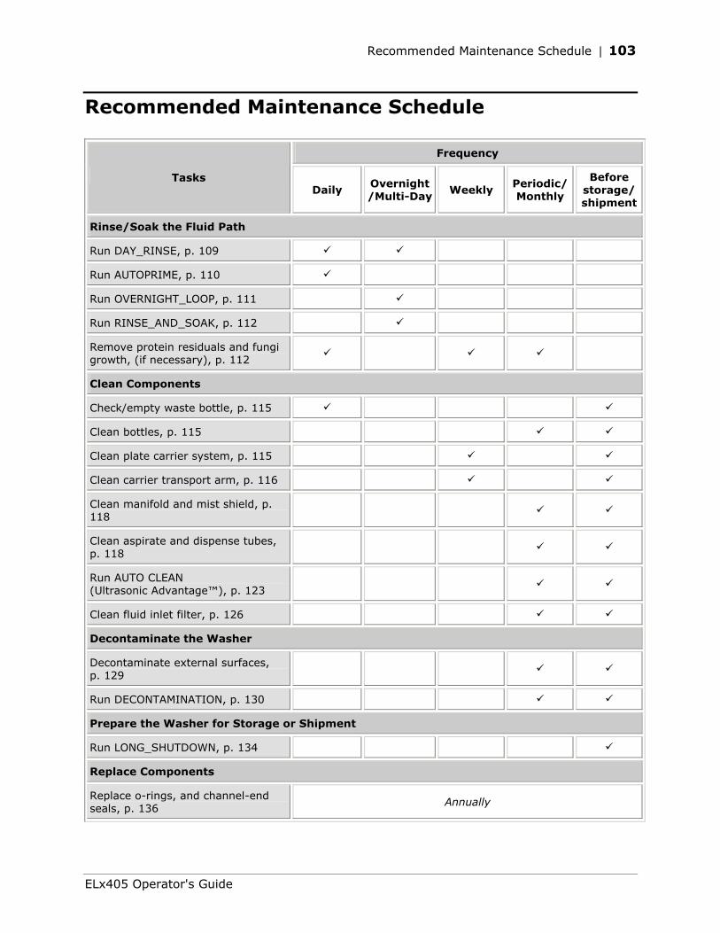
Recommended Maintenance Schedule | 103
Recommended Maintenance Schedule
Frequency
Tasks Daily
Overnight/Multi-Day Weekly
Periodic/ Monthly
Before storage/ shipment
Rinse/Soak the Fluid Path
Run DAY_RINSE, p. 109
Run AUTOPRIME, p. 110
Run OVERNIGHT_LOOP, p. 111
Run RINSE_AND_SOAK, p. 112
Remove protein residuals and fungi growth, (if necessary), p. 112
Clean Components
Check/empty waste bottle, p. 115
Clean bottles, p. 115
Clean plate carrier system, p. 115
Clean carrier transport arm, p. 116
Clean manifold and mist shield, p. 118
Clean aspirate and dispense tubes, p. 118
Run AUTO CLEAN (Ultrasonic Advantage™), p. 123
Clean fluid inlet filter, p. 126
Decontaminate the Washer
Decontaminate external surfaces, p. 129
Run DECONTAMINATION, p. 130
Prepare the Washer for Storage or Shipment
Run LONG_SHUTDOWN, p. 134
Replace Components
Replace o-rings, and channel-end seals, p. 136
Annually
ELx405 Operator's Guide
104 | Chapter 4: Preventive Maintenance
Required Materials
For rinsing/soaking the fluid path, and for cleaning the components:
• Deionized or distilled water
• Sodium hypochlorite (NaClO or bleach)
• 70% isopropyl alcohol (or ethanol)
• Dispense and aspirate tube styluses (supplied with the washer)
• Phillips head screwdriver
• 9/64” (3.57 mm) hex wrench (supplied with the washer)
• Lint-free disposable towels
• Dish soap or other mild cleaner
• Soft-bristled brush
For replacing o-rings and channel-end seals:
• O-rings (PN 49941)
• Channel-end seals (PN 49486)
In the following cleaning procedures, when not otherwise specified, “water” means use either deionized or distilled water.
Unless otherwise instructed, always connect a supply bottle containing deionized or distilled water to the washer before running the Maintenance programs.
Bio-Tek Instruments, Inc.
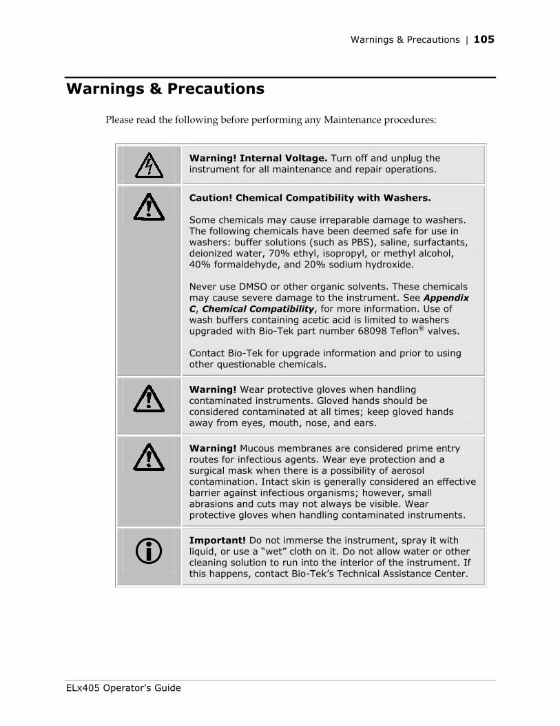
Warnings & Precautions | 105
Warnings & Precautions
Please read the following before performing any Maintenance procedures:
Warning! Internal Voltage. Turn off and unplug the instrument for all maintenance and repair operations.
Caution! Chemical Compatibility with Washers.
Some chemicals may cause irreparable damage to washers. The following chemicals have been deemed safe for use in washers: buffer solutions (such as PBS), saline, surfactants, deionized water, 70% ethyl, isopropyl, or methyl alcohol, 40% formaldehyde, and 20% sodium hydroxide.
Never use DMSO or other organic solvents. These chemicals may cause severe damage to the instrument. See Appendix C, Chemical Compatibility, for more information. Use of wash buffers containing acetic acid is limited to washers upgraded with Bio-Tek part number 68098 Teflon® valves.
Contact Bio-Tek for upgrade information and prior to using other questionable chemicals.
Warning! Wear protective gloves when handling contaminated instruments. Gloved hands should be considered contaminated at all times; keep gloved hands away from eyes, mouth, nose, and ears.
Warning! Mucous membranes are considered prime entry routes for infectious agents. Wear eye protection and a surgical mask when there is a possibility of aerosol contamination. Intact skin is generally considered an effective barrier against infectious organisms; however, small abrasions and cuts may not always be visible. Wear protective gloves when handling contaminated instruments.
Important! Do not immerse the instrument, spray it with liquid, or use a “wet” cloth on it. Do not allow water or other cleaning solution to run into the interior of the instrument. If this happens, contact Bio-Tek’s Technical Assistance Center.
ELx405 Operator's Guide
106 | Chapter 4: Preventive Maintenance
Maintenance Programs
The ELx405 onboard software contains the following pre-defined Maintenance programs for most of the recommended tasks:
• DAY_RINSE
• OVERNIGHT_LOOP
• RINSE_AND_SOAK
• LONG_SHUTDOWN
• DECONTAMINATION
To run a Maintenance program:
1. From the washer’s main menu, select MAINT.
2. Press the Options key to scroll through the available programs. Press the ENTER key to select a program.
3. If prompted for additional information (such as RINSE VALVE for models with the external valve module), make the appropriate selections.
4. When START MAINTENANCE? appears, select YES or press the START key to begin.
To halt a Maintenance program in progress, press the STOP key.
5. When the program is complete, press the Main Menu key to return to the washer’s main menu.
Bio-Tek Instruments, Inc.
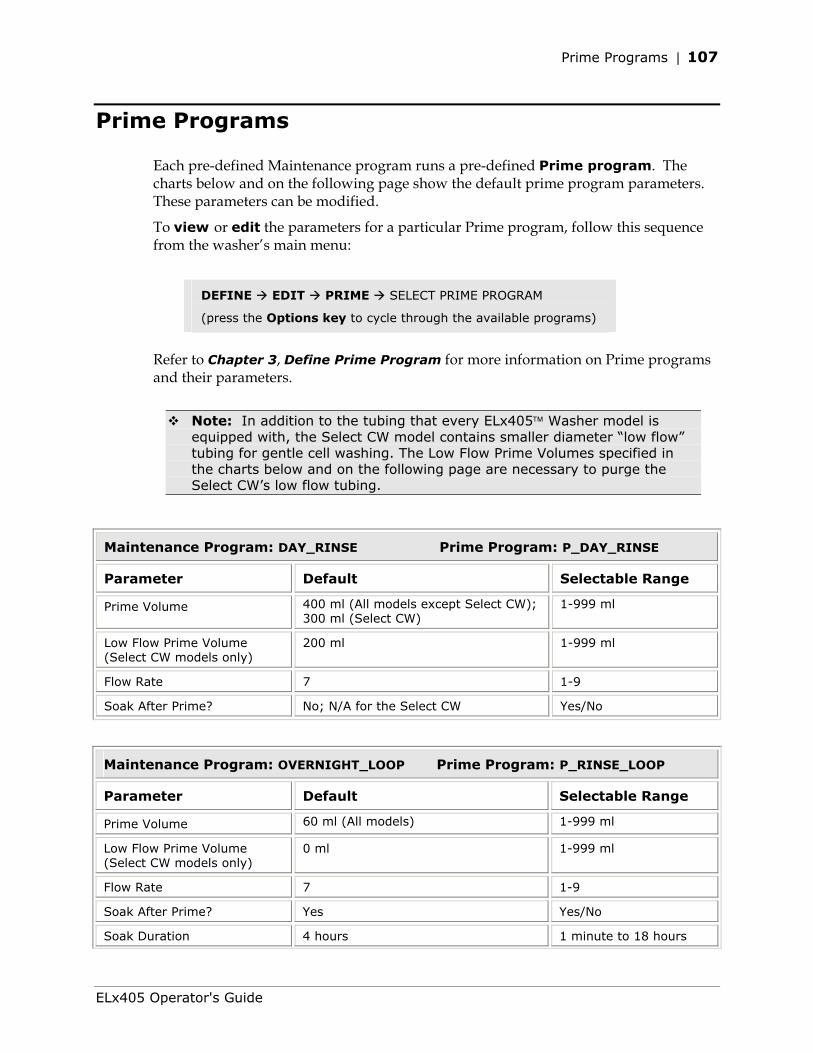
Prime Programs | 107
Prime Programs
Each pre-defined Maintenance program runs a pre-defined Prime program. The charts below and on the following page show the default prime program parameters. These parameters can be modified.
To view or edit the parameters for a particular Prime program, follow this sequence from the washer’s main menu:
DEFINE EDIT PRIME SELECT PRIME PROGRAM
(press the Options key to cycle through the available programs)
Refer to Chapter 3, Define Prime Program for more information on Prime programs and their parameters.
Note: In addition to the tubing that every ELx405 Washer model is equipped with, the Select CW model contains smaller diameter “low flow” tubing for gentle cell washing. The Low Flow Prime Volumes specified in the charts below and on the following page are necessary to purge the Select CW’s low flow tubing.
Maintenance Program: DAY_RINSE Prime Program: P_DAY_RINSE
Parameter Default Selectable Range
Prime Volume 400 ml (All models except Select CW); 300 ml (Select CW)
1-999 ml
Low Flow Prime Volume (Select CW models only)
200 ml 1-999 ml
Flow Rate 7 1-9
Soak After Prime? No; N/A for the Select CW Yes/No
Maintenance Program: OVERNIGHT_LOOP Prime Program: P_RINSE_LOOP
Parameter Default Selectable Range
Prime Volume 60 ml (All models) 1-999 ml
Low Flow Prime Volume (Select CW models only)
0 ml 1-999 ml
Flow Rate 7 1-9
Soak After Prime? Yes Yes/No
Soak Duration 4 hours 1 minute to 18 hours
ELx405 Operator's Guide
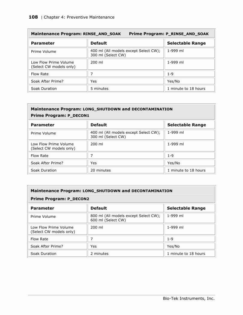
108 | Chapter 4: Preventive Maintenance
Maintenance Program: RINSE_AND_SOAK Prime Program: P_RINSE_AND_SOAK
Parameter Default Selectable Range
Prime Volume 400 ml (All models except Select CW); 300 ml (Select CW)
1-999 ml
Low Flow Prime Volume (Select CW models only)
200 ml 1-999 ml
Flow Rate 7 1-9
Soak After Prime? Yes Yes/No
Soak Duration 5 minutes 1 minute to 18 hours
Maintenance Program: LONG_SHUTDOWN and DECONTAMINATION
Prime Program: P_DECON1
Parameter Default Selectable Range
Prime Volume 400 ml (All models except Select CW); 300 ml (Select CW)
1-999 ml
Low Flow Prime Volume (Select CW models only)
200 ml 1-999 ml
Flow Rate 7 1-9
Soak After Prime? Yes Yes/No
Soak Duration 20 minutes 1 minute to 18 hours
Maintenance Program: LONG_SHUTDOWN and DECONTAMINATION
Prime Program: P_DECON2
Parameter Default Selectable Range
Prime Volume 800 ml (All models except Select CW); 600 ml (Select CW)
1-999 ml
Low Flow Prime Volume (Select CW models only)
200 ml 1-999 ml
Flow Rate 7 1-9
Soak After Prime? Yes Yes/No
Soak Duration 2 minutes 1 minute to 18 hours
Bio-Tek Instruments, Inc.
Rinse/Soak the Fluid Path | 109
Rinse/Soak the Fluid Path
Daily Maintenance
Daily maintenance involves flushing the washer with an appropriate reagent or deionized water throughout the day. Routinely rinsing the washer helps to prevent the aspirate and dispense tubes from clogging between washes.
The recommended rinsing frequency depends on the wash solutions currently in use:
• If a solution containing surfactant is used throughout the day, the rinsing procedure should be performed if the washer is idle for more than 3 hours.
• If the solution does not contain surfactant, consider rinsing at least once an hour.
The DAY_RINSE and AUTOPRIME programs described below and on the following page satisfy daily maintenance requirements.
DAY_RINSE
The DAY_RINSE Maintenance program primes the washer with the Prime Volume specified in the P_DAY_RINSE prime program. To view or edit the parameters in this Prime program, see Prime Programs on page 107.
To run the DAY_RINSE program, follow this sequence:
Washers not equipped with the external valve module:
MAINT SELECT MAINT PROGRAM: DAY_RINSE
CONNECT RINSE AND PRESS <START> KEY
Washers equipped with the external valve module:
MAINT SELECT MAINT PROGRAM: DAY_RINSE
RINSE VALVE? A B C or D START MAINTENANCE? YES
ELx405 Operator's Guide
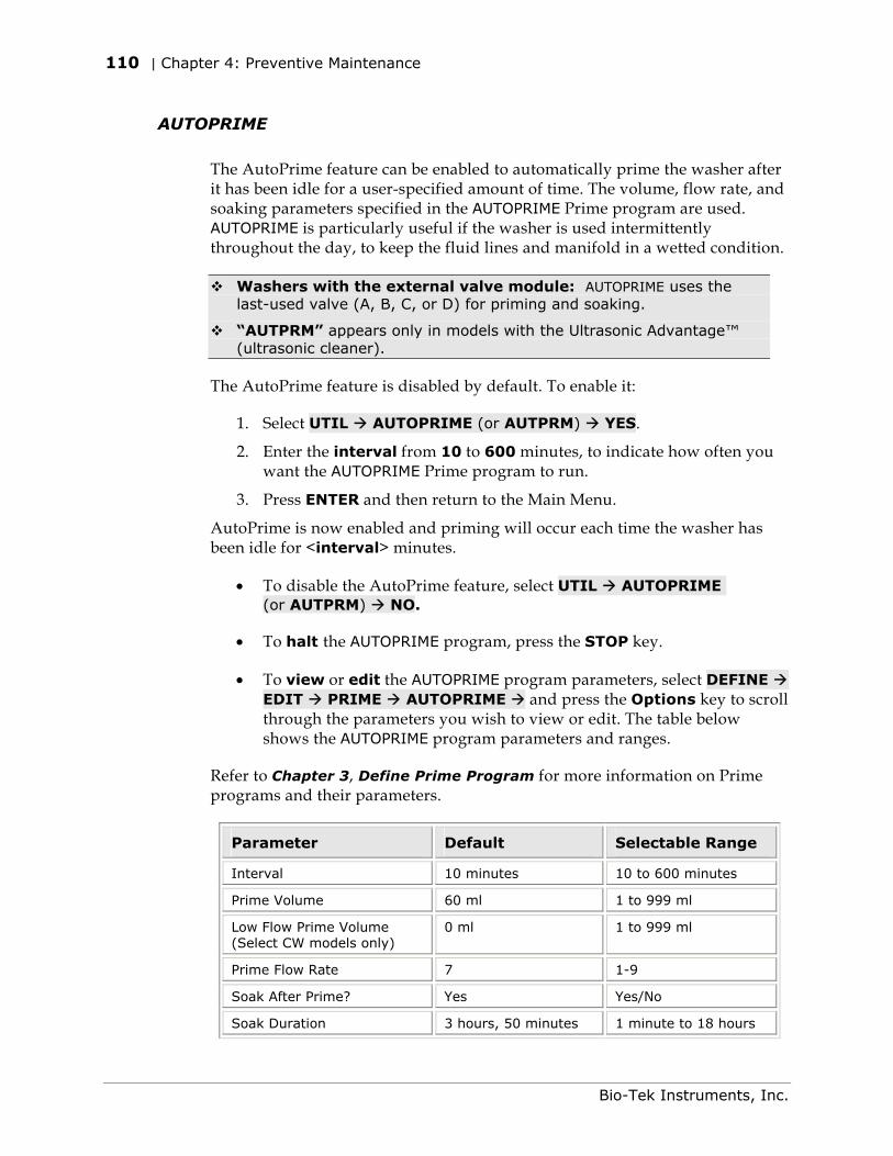
110 | Chapter 4: Preventive Maintenance
AUTOPRIME
The AutoPrime feature can be enabled to automatically prime the washer after it has been idle for a user-specified amount of time. The volume, flow rate, and soaking parameters specified in the AUTOPRIME Prime program are used. AUTOPRIME is particularly useful if the washer is used intermittently throughout the day, to keep the fluid lines and manifold in a wetted condition.
Washers with the external valve module: AUTOPRIME uses the last-used valve (A, B, C, or D) for priming and soaking.
“AUTPRM” appears only in models with the Ultrasonic Advantage™ (ultrasonic cleaner).
The AutoPrime feature is disabled by default. To enable it:
1. Select UTIL AUTOPRIME (or AUTPRM) YES.
2. Enter the interval from 10 to 600 minutes, to indicate how often you want the AUTOPRIME Prime program to run.
3. Press ENTER and then return to the Main Menu.
AutoPrime is now enabled and priming will occur each time the washer has been idle for <interval> minutes.
• To disable the AutoPrime feature, select UTIL AUTOPRIME (or AUTPRM) NO.
• To halt the AUTOPRIME program, press the STOP key.
• To view or edit the AUTOPRIME program parameters, select DEFINE EDIT PRIME AUTOPRIME and press the Options key to scroll through the parameters you wish to view or edit. The table below shows the AUTOPRIME program parameters and ranges.
Refer to Chapter 3, Define Prime Program for more information on Prime programs and their parameters.
Parameter Default Selectable Range
Interval 10 minutes 10 to 600 minutes
Prime Volume 60 ml 1 to 999 ml
Low Flow Prime Volume (Select CW models only)
0 ml 1 to 999 ml
Prime Flow Rate 7 1-9
Soak After Prime? Yes Yes/No
Soak Duration 3 hours, 50 minutes 1 minute to 18 hours
Bio-Tek Instruments, Inc.
Rinse/Soak the Fluid Path | 111
Overnight/Multi-Day Maintenance
Overnight/multi-day maintenance involves flushing all wash solution out of the instrument, and then periodically rinsing and soaking the tubes to keep them moist. If the washer will be left idle for a period of time (such as overnight or over a weekend), the tubes should be left to soak for several hours at a time.
The OVERNIGHT_LOOP and RINSE_AND_SOAK programs described below and on the following page satisfy overnight/multi-day maintenance requirements.
• The OVERNIGHT_LOOP program requires the washer to remain turned on.
• As an alternative, run RINSE_AND_SOAK and turn off the washer after the soak begins. This leaves the tubes soaking in the priming trough until the instrument is turned on again.
If the washer will be left idle for two or more days, run DAY_RINSE and OVERNIGHT_LOOP or run RINSE_AND_SOAK.
Important! Keep the manifold in a wetted condition to ensure proper evacuation of fluid. Bio-Tek recommends changing the Soak Duration to 18 hours for overnights and weekends when the washer is not being used. This will decrease flow problems and is a more trouble-free way to operate the washer.
OVERNIGHT_LOOP
The OVERNIGHT_LOOP Maintenance program primes and soaks the washer with the Prime Volume and Soak Duration specified in the P_RINSE_LOOP Prime program. To view or edit the parameters in this Prime program, see Prime Programs on page 107.
To run the OVERNIGHT_LOOP program, follow this sequence:
Washers not equipped with the external valve module:
MAINT SELECT MAINT PROGRAM: OVERNIGHT_LOOP
CONNECT RINSE AND PRESS <START> KEY
Washers equipped with the external valve module:
MAINT SELECT MAINT PROGRAM: OVERNIGHT_LOOP
RINSE VALVE? A B C or D START MAINTENANCE? YES
ELx405 Operator's Guide
112 | Chapter 4: Preventive Maintenance
RINSE_AND_SOAK
The RINSE_AND_SOAK Maintenance program primes and soaks the washer with the Prime Volume and Soak Duration specified in the P_RINSE_AND_SOAK Prime program. To view or edit the parameters in this Prime program, see Prime Programs on page 107.
To run the RINSE_AND_SOAK program, follow this sequence and turn off the washer after the soak begins:
Washers not equipped with the external valve module:
MAINT SELECT MAINT PROGRAM RINSE_AND_SOAK
CONNECT RINSE AND PRESS <START> KEY
Washers equipped with the external valve module:
MAINT SELECT MAINT PROGRAM RINSE_AND_SOAK
RINSE VALVE? A B C or D START MAINTENANCE? YES
Removing Protein Residuals and Fungi Growth
Important! Solutions containing proteins, such as bovine serum albumin (BSA), will compromise the washer’s performance over time unless a strict maintenance regime is adhered to.
Do not use isopropyl alcohol to flush out BSA.
Bio-Tek recommends performing the following additional Maintenance procedures to thoroughly flush out protein particles and other contaminants from the washer’s fluid path, if necessary:
Four-liter volumes specified in the following are approximate amounts.
Daily
Using an Enzyme-Active Detergent:
1 Mix an enzyme-active detergent according to the manufacturer’s directions to fill a four-liter supply bottle. Connect the bottle to the washer (Valve “A” if the valve module is connected).
2 Run the DECONTAMINATION program. When the program pauses and displays CONNECT RINSE BOTTLE AND PRESS <START> KEY, leave the detergent bottle connected and press the Start key to continue. Repeat this sequence until the bottle is empty.
Bio-Tek Instruments, Inc.
Rinse/Soak the Fluid Path | 113
3 Connect a bottle containing four liters of deionized water and run the P_DAY_RINSE Prime program three times to flush the system.
Using Ethanol:
At the end of the day:
1 Prepare a four-liter solution of 10% ethanol and deionized water. (Do not use isopropyl alcohol.) Connect the bottle to the washer (Valve “A” if the valve module is connected).
2 Run the DECONTAMINATION Maintenance program.
3 Connect a bottle containing four liters of deionized water and flush the system by running either the P_DAY_RINSE Prime program (three times), or the OVERNIGHT_LOOP Maintenance program.
Using Deionized Water:
If the washer will be idle between plates for longer than 45 minutes, flush the proteins from the washer:
1 Fill a supply bottle with deionized water. Connect the bottle to the washer (Valve “A” if the valve module is connected).
2 Run the P_DAY_RINSE Prime program.
3 Enable AUTOPRIME for 60-minute intervals.
At the end of the day:
1 Fill a supply bottle with deionized water. Connect the bottle to the washer (Valve “A” if the valve module is connected).
2 Run the P_DAY_RINSE Prime program three times.
3 Run the OVERNIGHT_LOOP Maintenance program.
Weekly/Monthly
1 Flush the system with 0.1-0.5 N NaOH, followed by neutralization with an equivalent normality (0.1-0.5 N) of HCl.
2 Rinse well with deionized water to remove the HCl.
3 Run the OVERNIGHT_LOOP Maintenance program with deionized water, or run the P_DAY_RINSE Prime program three times with deionized water if you plan to use the washer immediately.
ELx405 Operator's Guide
114 | Chapter 4: Preventive Maintenance
Clean Components
Periodic Maintenance
Periodic maintenance involves cleaning the washer components on a regular basis to keep the washer running efficiently and in compliance with instrument specifications. The recommended frequency for cleaning washer components is at least monthly. The risk and performance factors associated with your assays may require that some or all of the procedures be performed more frequently.
Warning! Internal Voltage. Turn off and unplug the washer for all cleaning operations.
Important! Do not apply lubricants to manifold o-rings, channel-end seals, bottle cover seals, any tubing connection, or any surface that is a part of the fluid path. The use of any lubricant on the fluid handling components will interfere with the aspirate and dispense performance, and may cause irreparable damage to these components.
Important! When cleaning components:
• Do not immerse the instrument, spray it with liquid, or use a “wet” cloth on it.
• Do not allow the cleaning solution to run into the interior of the instrument. (If this happens, contact the Bio-Tek Service Department.)
• Do not expose any part of the instrument to the recommended diluted sodium hypochlorite solution (bleach) for more than 20 minutes. Prolonged contact may damage the instrument surfaces. Be certain to rinse and thoroughly wipe all surfaces.
• Do not soak the keypad. Instead, moisten a clean cloth with deionized or distilled water and wipe the keypad. Dry it immediately with a clean, dry cloth.
Important! HT models with the accessory 96-tube manifold (HT2/HTV2): Perform Periodic Maintenance on the manifold (96-tube or 192-tube) most frequently in use.
Ensure that the washer is configured for operation with the installed manifold (refer to Manifold Selection in Chapter 3, Operation.) Failure to set the manifold type before operating the washer may damage the manifold and void your warranty.
Bio-Tek Instruments, Inc.
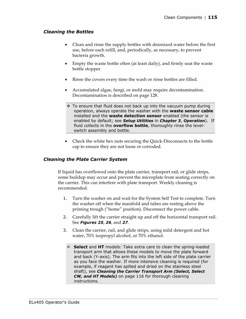
Clean Components | 115
Cleaning the Bottles
• Clean and rinse the supply bottles with deionized water before the first use, before each refill, and, periodically, as necessary, to prevent bacteria growth.
• Empty the waste bottle often (at least daily), and firmly seat the waste bottle stopper.
• Rinse the covers every time the wash or rinse bottles are filled.
• Accumulated algae, fungi, or mold may require decontamination. Decontamination is described on page 128.
To ensure that fluid does not back up into the vacuum pump during operation, always operate the washer with the waste sensor cable installed and the waste detection sensor enabled (the sensor is enabled by default; see Setup Utilities in Chapter 3, Operation). If fluid collects in the overflow bottle, thoroughly rinse the level-switch assembly and bottle.
• Check the white hex nuts securing the Quick-Disconnects to the bottle cap to ensure they are not loose or corroded.
Cleaning the Plate Carrier System
If liquid has overflowed onto the plate carrier, transport rail, or glide strips, some buildup may occur and prevent the microplate from seating correctly on the carrier. This can interfere with plate transport. Weekly cleaning is recommended.
1. Turn the washer on and wait for the System Self Test to complete. Turn the washer off when the manifold and tubes are resting above the priming trough (“home” position). Disconnect the power cable.
2. Carefully lift the carrier straight up and off the horizontal transport rail. See Figures 25, 26, and 27.
3. Clean the carrier, rail, and glide strips, using mild detergent and hot water, 70% isopropyl alcohol, or 70% ethanol.
Select and HT models: Take extra care to clean the spring-loaded
transport arm that allows these models to move the plate forward and back (Y-axis). The arm fits into the left side of the plate carrier as you face the washer. If more intensive cleaning is required (for example, if reagent has spilled and dried on the stainless steel shaft), see Cleaning the Carrier Transport Arm (Select, Select CW, and HT Models) on page 116 for thorough cleaning instructions.
ELx405 Operator's Guide
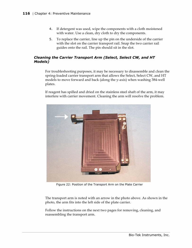
116 | Chapter 4: Preventive Maintenance
4. If detergent was used, wipe the components with a cloth moistened
with water. Use a clean, dry cloth to dry the components.
5. To replace the carrier, line up the pin on the underside of the carrier with the slot on the carrier transport rail. Snap the two carrier rail guides onto the rail. The pin should sit in the slot.
Cleaning the Carrier Transport Arm (Select, Select CW, and HT Models)
For troubleshooting purposes, it may be necessary to disassemble and clean the spring-loaded carrier transport arm that allows the Select, Select CW, and HT models to move forward and back (along the y-axis) when washing 384-well plates.
If reagent has spilled and dried on the stainless steel shaft of the arm, it may interfere with carrier movement. Cleaning the arm will resolve the problem.
Figure 22: Position of the Transport Arm on the Plate Carrier
The transport arm is noted with an arrow in the photo above. As shown in the photo, the arm fits into the left side of the plate carrier.
Follow the instructions on the next two pages for removing, cleaning, and reassembling the transport arm.
Bio-Tek Instruments, Inc.
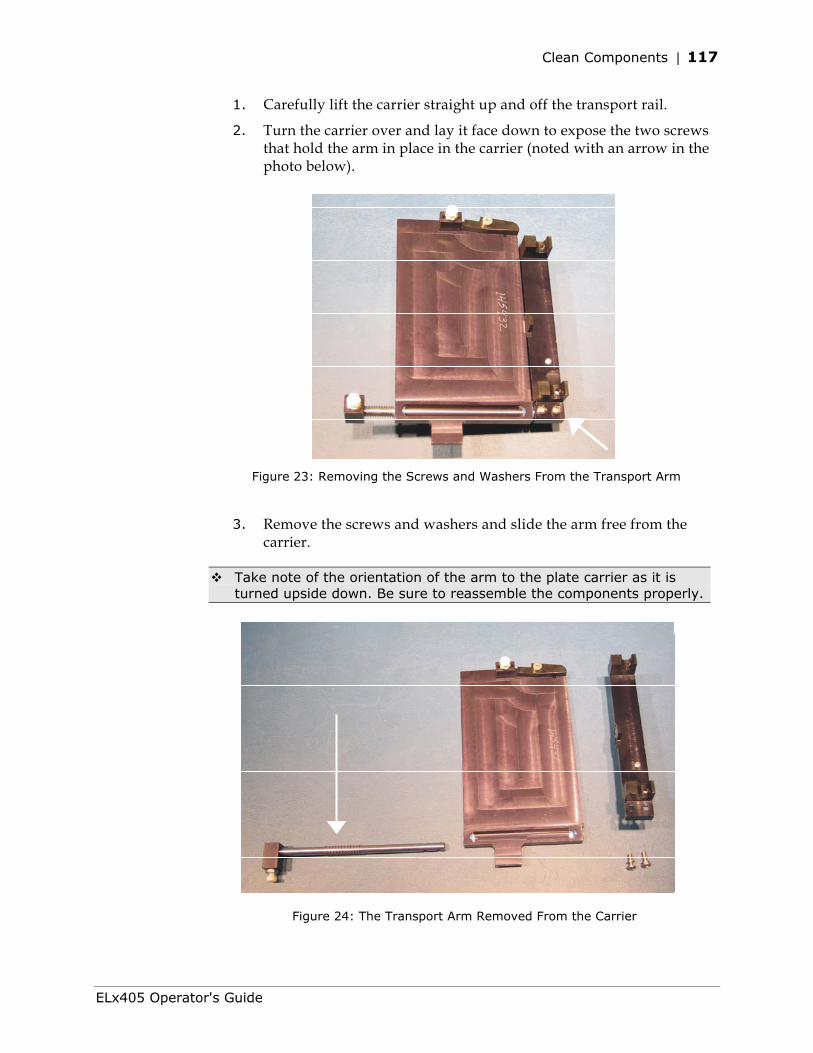
Clean Components | 117
1. Carefully lift the carrier straight up and off the transport rail.
2. Turn the carrier over and lay it face down to expose the two screws that hold the arm in place in the carrier (noted with an arrow in the photo below).
Figure 23: Removing the Screws and Washers From the Transport Arm
3. Remove the screws and washers and slide the arm free from the carrier.
Take note of the orientation of the arm to the plate carrier as it is turned upside down. Be sure to reassemble the components properly.
Figure 24: The Transport Arm Removed From the Carrier
ELx405 Operator's Guide
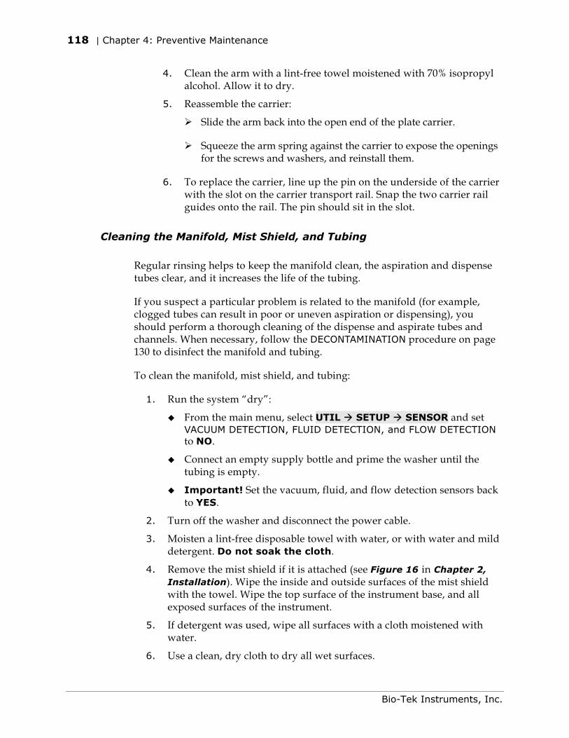
118 | Chapter 4: Preventive Maintenance
4. Clean the arm with a lint-free towel moistened with 70% isopropyl alcohol. Allow it to dry.
5. Reassemble the carrier:
Slide the arm back into the open end of the plate carrier.
Squeeze the arm spring against the carrier to expose the openings for the screws and washers, and reinstall them.
6. To replace the carrier, line up the pin on the underside of the carrier with the slot on the carrier transport rail. Snap the two carrier rail guides onto the rail. The pin should sit in the slot.
Cleaning the Manifold, Mist Shield, and Tubing
Regular rinsing helps to keep the manifold clean, the aspiration and dispense tubes clear, and it increases the life of the tubing.
If you suspect a particular problem is related to the manifold (for example, clogged tubes can result in poor or uneven aspiration or dispensing), you should perform a thorough cleaning of the dispense and aspirate tubes and channels. When necessary, follow the DECONTAMINATION procedure on page 130 to disinfect the manifold and tubing.
To clean the manifold, mist shield, and tubing:
1. Run the system “dry”:
From the main menu, select UTIL SETUP SENSOR and set VACUUM DETECTION, FLUID DETECTION, and FLOW DETECTION to NO.
Connect an empty supply bottle and prime the washer until the tubing is empty.
Important! Set the vacuum, fluid, and flow detection sensors back to YES.
2. Turn off the washer and disconnect the power cable.
3. Moisten a lint-free disposable towel with water, or with water and mild detergent. Do not soak the cloth.
4. Remove the mist shield if it is attached (see Figure 16 in Chapter 2, Installation). Wipe the inside and outside surfaces of the mist shield with the towel. Wipe the top surface of the instrument base, and all exposed surfaces of the instrument.
5. If detergent was used, wipe all surfaces with a cloth moistened with water.
6. Use a clean, dry cloth to dry all wet surfaces.
Bio-Tek Instruments, Inc.
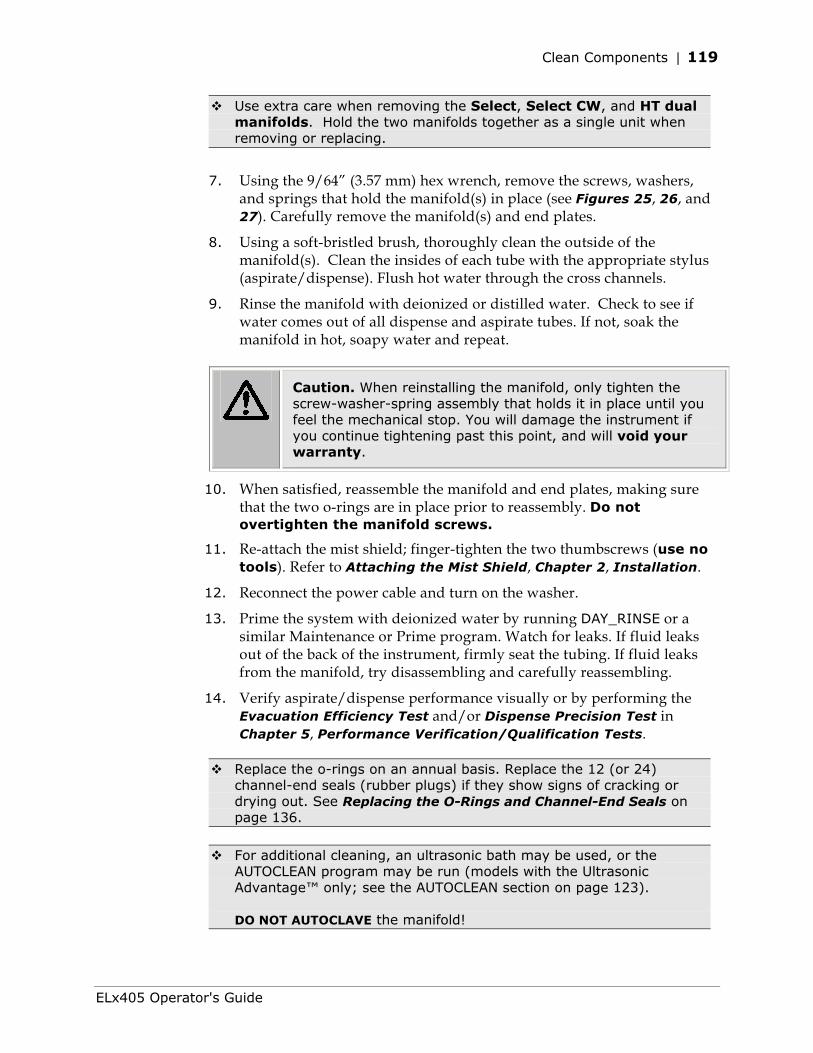
Clean Components | 119
Use extra care when removing the Select, Select CW, and HT dual manifolds. Hold the two manifolds together as a single unit when removing or replacing.
7. Using the 9/64” (3.57 mm) hex wrench, remove the screws, washers, and springs that hold the manifold(s) in place (see Figures 25, 26, and 27). Carefully remove the manifold(s) and end plates.
8. Using a soft-bristled brush, thoroughly clean the outside of the manifold(s). Clean the insides of each tube with the appropriate stylus (aspirate/dispense). Flush hot water through the cross channels.
9. Rinse the manifold with deionized or distilled water. Check to see if water comes out of all dispense and aspirate tubes. If not, soak the manifold in hot, soapy water and repeat.
Caution. When reinstalling the manifold, only tighten the screw-washer-spring assembly that holds it in place until you feel the mechanical stop. You will damage the instrument if you continue tightening past this point, and will void your warranty.
10. When satisfied, reassemble the manifold and end plates, making sure that the two o-rings are in place prior to reassembly. Do not overtighten the manifold screws.
11. Re-attach the mist shield; finger-tighten the two thumbscrews (use no tools). Refer to Attaching the Mist Shield, Chapter 2, Installation.
12. Reconnect the power cable and turn on the washer.
13. Prime the system with deionized water by running DAY_RINSE or a similar Maintenance or Prime program. Watch for leaks. If fluid leaks out of the back of the instrument, firmly seat the tubing. If fluid leaks from the manifold, try disassembling and carefully reassembling.
14. Verify aspirate/dispense performance visually or by performing the Evacuation Efficiency Test and/or Dispense Precision Test in Chapter 5, Performance Verification/Qualification Tests.
Replace the o-rings on an annual basis. Replace the 12 (or 24) channel-end seals (rubber plugs) if they show signs of cracking or drying out. See Replacing the O-Rings and Channel-End Seals on page 136.
For additional cleaning, an ultrasonic bath may be used, or the
AUTOCLEAN program may be run (models with the Ultrasonic Advantage™ only; see the AUTOCLEAN section on page 123). DO NOT AUTOCLAVE the manifold!
ELx405 Operator's Guide
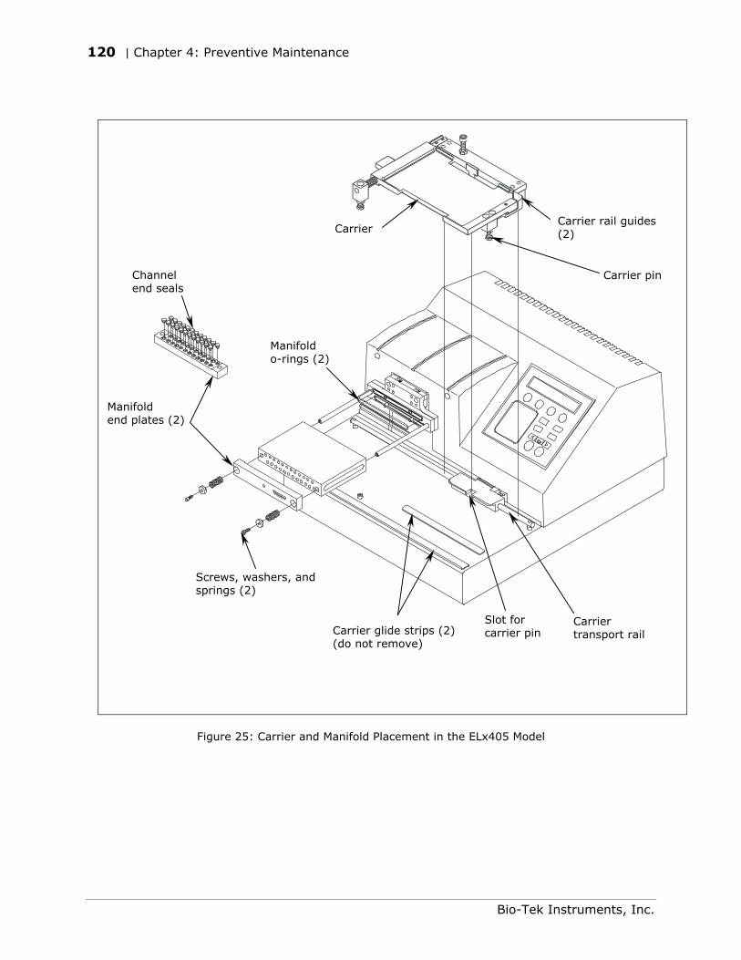
120 | Chapter 4: Preventive Maintenance
Carrier
Screws, washers, and springs (2)
Manifold o-rings (2)
Channel end seals
Manifold end plates (2)
Carrier pin
Carrier transport rail
Slot for carrier pin Carrier glide strips (2)
(do not remove)
Carrier rail guides (2)
Figure 25: Carrier and Manifold Placement in the ELx405 Model
Bio-Tek Instruments, Inc.
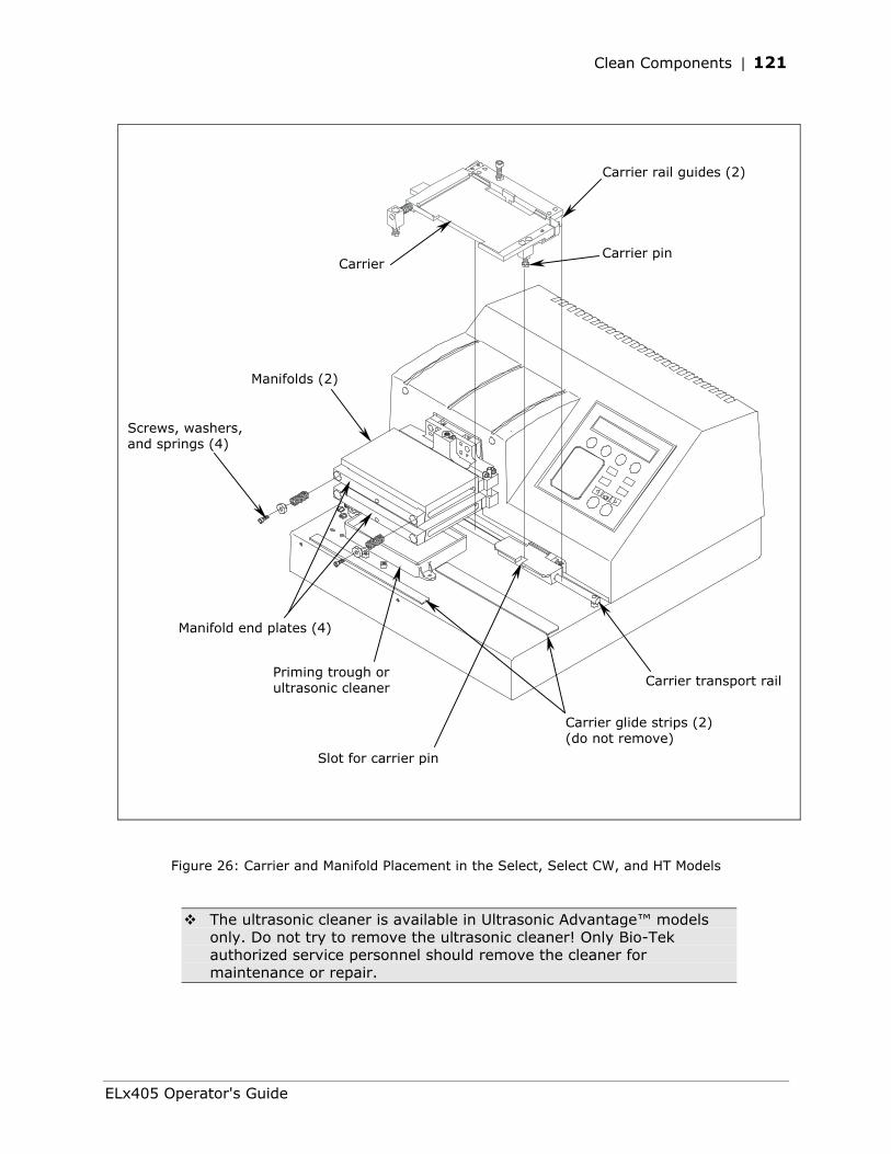
Clean Components | 121
Carrier rail guides (2)
Screws, washers, and springs (4)
Carrier glide strips (2) (do not remove)
Carrier pin
Carrier transport rail
Carrier
Manifold end plates (4)
Priming trough or ultrasonic cleaner
Manifolds (2)
Slot for carrier pin
Figure 26: Carrier and Manifold Placement in the Select, Select CW, and HT Models
The ultrasonic cleaner is available in Ultrasonic Advantage™ models only. Do not try to remove the ultrasonic cleaner! Only Bio-Tek authorized service personnel should remove the cleaner for maintenance or repair.
ELx405 Operator's Guide
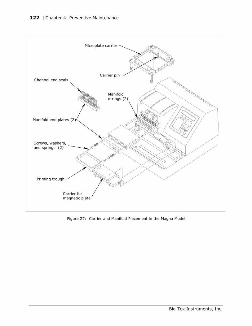
122 | Chapter 4: Preventive Maintenance
Screws, washers, and springs (2)
Channel end seals
Manifold end plates (2)
Priming trough
Carrier for magnetic plate
Manifold o-rings (2)
Microplate carrier
Carrier pin
Figure 27: Carrier and Manifold Placement in the Magna Model
Bio-Tek Instruments, Inc.
Clean Components | 123
AUTOCLEAN (for Ultrasonic Advantage™ models only)
Warning! Ultrasonic energy is present in the cleaning reservoir when an AUTOCLEAN program is running. Do not put your fingers in the bath! Ultrasonic energy can be destructive to human tissue.
Important! Ensure that adequate room exists in the vacuum bottle and adequate volume is available in the supply bottle before running an AUTOCLEAN program!
Ultrasonic Advantage™ models feature a built-in ultrasonic cleaner that provides enhanced periodic maintenance capabilities by using ultrasonic pulses in a water bath to clean residuals from the manifold tubes. Ultrasonic energy causes cavitation forces within the water bath, which in turn cause tiny vapor bubbles to be created. The formation and subsequent collapse of these bubbles is the mechanism that cleans manifold tubes submerged in the bath. The cleaner consists of a stainless steel reservoir with an ultrasonic transducer bonded to the bottom of the reservoir. The reservoir is mounted on the washer in the same position as the priming trough in other models.
Do not try to remove the ultrasonic cleaner! Only Bio-Tek authorized service personnel should remove the ultrasonic cleaner for maintenance or repair.
The onboard AUTOCLEAN (AUTCL) function in the Utility menu enables you to define and run an ultrasonic cleaning program that includes one or more cleaning “loops.” Use multiple loops if you want to clean with more than one type of fluid.
AUTOCLEAN Parameter Selectable Range
Number of Loops 1-10 loops
Duration of each loop 1-60 minutes
Supply bottles A-D for valve modules
ELx405 Operator's Guide
124 | Chapter 4: Preventive Maintenance
Tip: Detergent such as Terg-A-Zyme® added to deionized water in the supply bottle helps to break down the water’s surface tension and enhances the cleaning process. Terg-A-Zyme® also contains protease enzyme for assimilating protinaceous residue such as bovine serum albumin (BSA). Run one or more loops in the cleaning program for 30 minutes in each loop. Follow with a rinse loop using deionized water to remove the detergent from the system, or with a wash buffer to leave the instrument primed and ready for use.
Prepare the waste and supply bottles
Empty the waste bottle. Ensure that there is a sufficient volume of deionized water and detergent in the supply bottle(s): An AUTOCLEAN program initially primes the system with 200 ml of fluid from the supply bottle specified for Loop 1; each cleaning loop fills the reservoir with approximately 93 ml of fluid.
Priming with 200 ml is always done for each successive loop in models without the valve module, and in models with the valve module, if the valve selection changes between loops.
Define the AUTOCLEAN program parameters:
From the washer’s main menu, follow the path below:
Washers not equipped with the external valve module:
UTIL AUTCL DEFINE AUTOCLEAN NUM LOOPS: Enter 01 to 10 loops LOOP <loop number> DURATION: Enter 01 to 60 minutes OK TO SAVE PROGRAM? YES
Washers equipped with the external valve module:
UTIL AUTCL DEFINE AUTOCLEAN NUM LOOPS: Enter 01 to 10 loops LOOP <loop number> DURATION: Enter 01 to 60 minutes LOOP <loop number> VALVE: Select A, B, C, or D OK TO SAVE PROGRAM? YES
Bio-Tek Instruments, Inc.
Clean Components | 125
Run the AUTOCLEAN program:
From the washer’s main menu, select UTIL AUTCL RUN.
The program begins with a priming sequence. When priming is complete, the manifold lowers into the reservoir, the washer dispenses approximately 93 ml of fluid, and cleaning LOOP 01 begins. When the loop is complete, the washer aspirates the fluid from the reservoir.
If another loop is specified in the program, the washer is primed (only if valve selection changes or if operating without the valve module), fluid is dispensed, and the next loop begins. This process is repeated until all loops are complete.
Models without the valve module: If more than one cleaning loop is defined, the washer will pause between loops and display “CONNECT SUPPLY <next loop number>” to allow you to switch supply bottles. Press the ENTER key to resume cleaning.
While the program is running, the ultrasonic cleaner will pulse on and off approximately every ten seconds (a 50% duty cycle), and you will hear a periodic “hissing” sound that indicates the ultrasonic energy is present.
When PROGRAM COMPLETE appears, select REPEAT to run the program again, or select STOP and press the Main Menu key.
ELx405 Operator's Guide
126 | Chapter 4: Preventive Maintenance
Cleaning the Fluid Inlet Filter
Warning! Internal Voltage. Turn off and unplug the washer for all cleaning operations.
Periodically clean the fluid inlet filter (PN 49943) that is located next to the vacuum port on the rear panel of the instrument. To clean the filter:
1. Unscrew the fluid inlet fitting from the back of the washer (see Figure 28).
2. Note the orientation of the filter in the fitting (the cone-shaped end of the filter points “in” toward the instrument) and then remove the filter from the housing.
3. Wash the filter with hot water and a soft-bristled brush.
4. Rinse the filter, then replace it in the fitting and reinstall onto the rear of the instrument.
Bio-Tek Instruments, Inc.
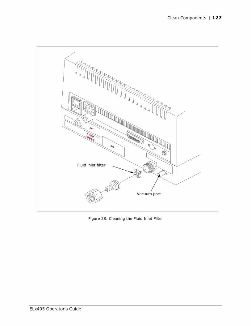
Clean Components | 127
Vacuum port
Fluid inlet filter
Figure 28: Cleaning the Fluid Inlet Filter
ELx405 Operator's Guide
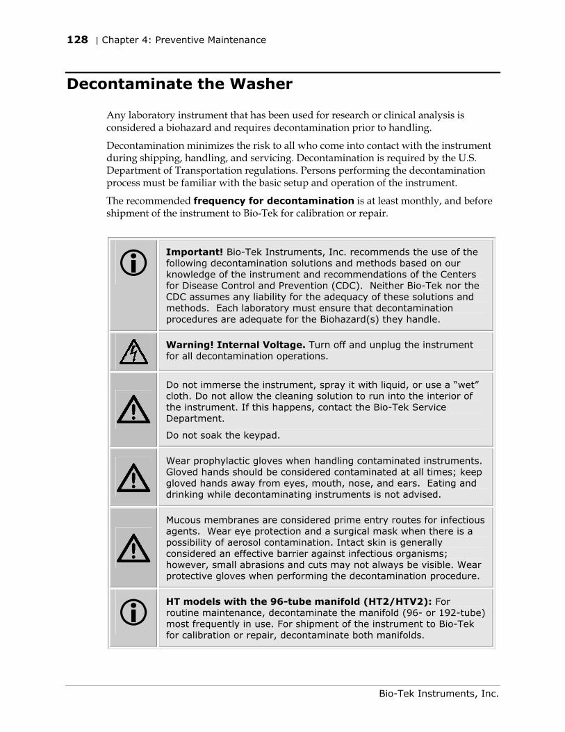
128 | Chapter 4: Preventive Maintenance
Decontaminate the Washer
Any laboratory instrument that has been used for research or clinical analysis is considered a biohazard and requires decontamination prior to handling.
Decontamination minimizes the risk to all who come into contact with the instrument during shipping, handling, and servicing. Decontamination is required by the U.S. Department of Transportation regulations. Persons performing the decontamination process must be familiar with the basic setup and operation of the instrument.
The recommended frequency for decontamination is at least monthly, and before shipment of the instrument to Bio-Tek for calibration or repair.
Important! Bio-Tek Instruments, Inc. recommends the use of the following decontamination solutions and methods based on our knowledge of the instrument and recommendations of the Centers for Disease Control and Prevention (CDC). Neither Bio-Tek nor the CDC assumes any liability for the adequacy of these solutions and methods. Each laboratory must ensure that decontamination procedures are adequate for the Biohazard(s) they handle.
Warning! Internal Voltage. Turn off and unplug the instrument for all decontamination operations.
Do not immerse the instrument, spray it with liquid, or use a “wet” cloth. Do not allow the cleaning solution to run into the interior of the instrument. If this happens, contact the Bio-Tek Service Department.
Do not soak the keypad.
Wear prophylactic gloves when handling contaminated instruments. Gloved hands should be considered contaminated at all times; keep gloved hands away from eyes, mouth, nose, and ears. Eating and drinking while decontaminating instruments is not advised.
Mucous membranes are considered prime entry routes for infectious agents. Wear eye protection and a surgical mask when there is a possibility of aerosol contamination. Intact skin is generally considered an effective barrier against infectious organisms; however, small abrasions and cuts may not always be visible. Wear protective gloves when performing the decontamination procedure.
HT models with the 96-tube manifold (HT2/HTV2): For routine maintenance, decontaminate the manifold (96- or 192-tube) most frequently in use. For shipment of the instrument to Bio-Tek for calibration or repair, decontaminate both manifolds.
Bio-Tek Instruments, Inc.
Decontaminate the Washer | 129
Decon Procedure for External Surfaces of the Instrument
The bleach solution is caustic; wear gloves and eye protection when handling this solution.
Caution! Be sure to check the percent NaClO of the bleach you are using; this information is printed on the side of the bottle. Commercial bleach is typically 10% NaClO; if this is the case, prepare a 1:20 dilution. Household bleach is typically 5% NaClO; if this is the case, prepare a 1:10 dilution.
1. Turn the washer off and disconnect the power cord. Empty the waste bottle.
2. Prepare an aqueous solution of 0.5% sodium hypochlorite (NaClO, or bleach). As an alternative, 70% isopropyl alcohol (or 70% ethanol) may be used if the effects of bleach are a concern.
Isopropyl alcohol is not recommended for removing proteins (such as bovine serum albumin).
3. Moisten a cloth with the bleach solution or alcohol. Do not soak the cloth.
Wipe the keypad (do not soak). Wipe again with a clean cloth moistened with deionized or distilled water. Dry immediately with a clean, dry cloth.
Remove the washer’s mist shield if it is attached. Wipe the inside and outside surfaces of the mist shield. Wipe the plate carrier, top surface of the instrument’s base, supply bottles and tubing, and all exposed surfaces of the instrument.
4. Wait 20 minutes. Moisten a cloth with DI or distilled water.
Wipe the inside and outside surfaces of the mist shield. Wipe the plate carrier, top surface of the instrument’s base, supply bottles, tubing, bottle covers and all exposed surfaces of the instrument that have been cleaned with the bleach solution or alcohol.
5. Use a clean, dry cloth to dry all wet surfaces.
6. Reassemble the instrument as necessary.
7. Discard the used gloves and cloths using a Biohazard trash bag and an approved Biohazard container.
ELx405 Operator's Guide
130 | Chapter 4: Preventive Maintenance
Decon Procedure for Tubing and Manifold
The recommended onboard Maintenance program is DECONTAMINATION. This program flushes and soaks the supply tubing and manifold with disinfectant, then flushes the system with rinse, and finally purges the system of fluid.
The LONG_SHUTDOWN program primes and soaks the washer with the Prime Volumes and Soak Durations specified in the P_DECON1 and P_DECON2 prime programs. These Prime programs can be edited for optimum cleaning. Refer to the charts in the Prime Programs section of this chapter for a list of default parameters and to Chapter 3, Operation, for instructions on editing these parameters.
Two supply bottles are required for this procedure: one for disinfectant, and one for rinse.
Caution! Be sure to check the percent NaClO of the bleach you are using; this information is printed on the side of the bottle. Commercial bleach is typically 10% NaClO; if this is the case, prepare a 1:20 dilution. Household bleach is typically 5% NaClO; if this is the case, prepare a 1:10 dilution.
1. Perform the decontamination procedure described on the previous page.
2. Turn the washer off and disconnect the power cord.
3. Empty the waste bottle.
4. Prepare an aqueous solution of 0.5% sodium hypochlorite (NaClO, or bleach).
5. Fill one supply bottle with at least 400 ml of bleach solution (disinfectant).
6. Fill another supply bottle with at least 800 ml of deionized water (rinse).
7. If the washer is equipped with the external valve module, connect the supply bottles this way:
• Valve A: Disinfectant bottle
• Valve B: Rinse solution bottle
8. Reconnect the power cord and turn on the washer.
9. To run the DECONTAMINATION program, follow this sequence:
While this program is running, you will need to periodically check the display panel and follow the instructions.
Bio-Tek Instruments, Inc.
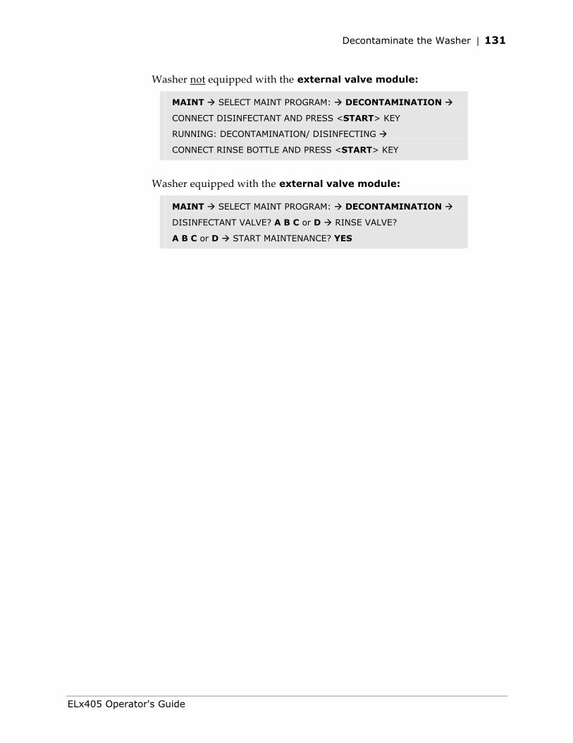
Decontaminate the Washer | 131
Washer not equipped with the external valve module:
MAINT SELECT MAINT PROGRAM: DECONTAMINATION
CONNECT DISINFECTANT AND PRESS <START> KEY
RUNNING: DECONTAMINATION/ DISINFECTING
CONNECT RINSE BOTTLE AND PRESS <START> KEY
Washer equipped with the external valve module:
MAINT SELECT MAINT PROGRAM: DECONTAMINATION
DISINFECTANT VALVE? A B C or D RINSE VALVE?
A B C or D START MAINTENANCE? YES
ELx405 Operator's Guide
132 | Chapter 4: Preventive Maintenance
Alternate Decontamination Procedure for Tubing and Manifold
If you are unable to run the DECONTAMINATION program due to a system failure, perform the following alternate decontamination procedure to disinfect the internal tubing and manifold.
Caution! Be sure to check the percent NaClO of the bleach you are using; this information is printed on the side of the bottle. Commercial bleach is typically 10% NaClO; if this is the case, prepare a 1:20 dilution. Household bleach is typically 5% NaClO; if this is the case, prepare a 1:10 dilution.
1. Turn the washer off and disconnect the power cord.
2. Remove the mist shield, if it is attached:
Using your fingers, loosen the two thumbscrews on the shield (use no tools).
Lift the shield off the two posts.
Refer to Decon Procedure for External Surfaces of the Instrument on page 129 for decontamination of the mist shield.
Use extra care when removing the Select, HT, and Select CW dual manifolds. Hold the two manifolds (and end plates) together as a single unit when removing or replacing.
3. Using the 9/64” (3.57 mm) hex wrench, remove the screws, washers, and springs that hold the manifold(s) in place (see Figures 25, 26, and 27). Remove the manifold(s) and end plates.
4. Prepare an aqueous solution of 0.5% sodium hypochlorite (bleach). As an alternative, 70% isopropyl alcohol (or ethanol) may be used if the effects of bleach are a concern.
Isopropyl alcohol is not recommended for removing proteins (such as bovine serum albumin).
5. Soak the tubing and manifold in the bleach or alcohol solution.
6. Wait 20 minutes. Rinse the tubing and manifold with DI or distilled water.
7. Use a clean, dry cloth to dry all wet surfaces of the tubes and manifold.
Bio-Tek Instruments, Inc.
Decontaminate the Washer | 133
Caution. When reinstalling the manifold, only tighten the screw-washer-spring assembly that holds it in place until you feel the mechanical stop. You will damage the instrument if you continue tightening past this point, and will void your warranty.
8. Reassemble the manifold and end plates, making sure that the two o-rings are in place prior to reassembly. Do not overtighten the manifold screws.
9. Re-attach the mist shield:
Align the mist shield with the washer so it is resting on top of the two posts, and the two thumbscrew holes in the shield are lined up with the two holes in the front base of the washer. (Refer to Figure 16 in the section Attaching the Mist Shield, Chapter 2.)
Insert the two thumbscrews and finger-tighten only (use no tools).
10. Prime the system by running DAY_RINSE or a similar Maintenance or Prime program. Watch for leaks. If fluid leaks out of the back of the instrument, firmly seat the tubing. If fluid leaks from the manifold, try disassembling and carefully reassembling.
11. Discard the used gloves and cloths using a Biohazard trash bag and an approved Biohazard container.
12. Verify dispenser performance visually or by performing the Dispense Precision Test in Chapter 5, Performance Verification/Qualification Tests.
ELx405 Operator's Guide
134 | Chapter 4: Preventive Maintenance
Prepare for Storage or Shipment
Before the washer is shipped or stored, it should be rinsed and soaked with disinfectant and then purged of all fluid. Perform these steps when leaving the washer unused for a long period of time.
Long_Shutdown
The recommended onboard Maintenance program is LONG_SHUTDOWN. This program flushes and soaks the supply tubing and manifold with disinfectant, then flushes the system with rinse, and finally purges the system of fluid.
For the ELx405™ HT2/HTV2: Before switching from one manifold to another (e.g., before removing the 192-tube manifold and installing the 96-tube manifold), Bio-Tek recommends that you perform this procedure to thoroughly clean whichever manifold will be removed and stored.
The LONG_SHUTDOWN Maintenance program primes and soaks the washer with the Prime Volumes and Soak Durations specified in the P_DECON1 and P_DECON2 Prime programs. These prime programs can be edited for optimum cleaning. Refer to the charts in the Prime Programs section of this chapter for a list of default Prime program parameters and to Chapter 3, Operation, for instructions on editing these parameters.
Three supply bottles are required for this procedure: one for disinfectant, one for rinse, and one for air.
Caution! Be sure to check the percent NaClO of the bleach you are using; this information is printed on the side of the bottle. Commercial bleach is typically 10% NaClO; if this is the case, prepare a 1:20 dilution. Household bleach is typically 5% NaClO; if this is the case, prepare a 1:10 dilution.
1. Turn off the instrument. Empty the waste bottle.
2. Prepare an aqueous solution of 0.5% sodium hypochlorite (NaClO, or bleach).
3. Fill one supply bottle with at least 400 ml of bleach solution (disinfectant).
4. Fill another supply bottle with at least 800 ml of deionized water (rinse).
5. Keep the third supply bottle empty (air).
Bio-Tek Instruments, Inc.
Prepare for Storage or Shipment | 135
6. If the washer is equipped with the external valve module, connect the supply bottles this way:
Valve A: Disinfectant bottle
Valve B: Rinse solution bottle
Valve C: Empty bottle
7. Turn on the washer.
8. To run the LONG_SHUTDOWN program, follow this sequence:
While this program is running, you will need to periodically check the display panel and follow the instructions.
Washers not equipped with the external valve module:
MAINT SELECT MAINT PROGRAM: LONG_SHUTDOWN
CONNECT DISINFECTANT AND PRESS <START> KEY
Washers equipped with the external valve module:
MAINT SELECT MAINT PROGRAM: LONG_SHUTDOWN
DISINFECTANT VALVE? A RINSE VALVE? B AIR VALVE? C
START MAINTENANCE? YES
Storing the Washer
After performing the Long_Shutdown procedure:
1. Turn off the washer and disconnect the power cord.
2. Store the washer on a flat surface that is relatively free of vibration, in a dust-free and particle-free environment.
3. Protect the washer from temperature extremes that can cause condensation within the unit and from corrosive fumes and vapors.
4. Store the washer under the following environmental conditions:
Temperature: –20° to 50°C (-4° to 122°F)
Relative humidity: 10% to 85% (non-condensing)
ELx405 Operator's Guide
136 | Chapter 4: Preventive Maintenance
Replace Components
Replacing the O-Rings and Channel-End Seals
For optimal performance and to extend the life of the washer, replace the manifold o-rings once a year and replace the 12 (or 24) rubber plugs (seals) on the channel ends if they show signs of cracking or drying out. Order the replacement o-rings and seals from Bio-Tek (see page 104).
You must remove the manifold to change the seals, so these tasks work best in conjunction with the Cleaning the Manifold, Mist Shield, and Tubing procedure on page 118.
Replacing the O-Rings
After completing Step 9 of the procedure on page 119:
1. Using your fingers or an appropriate tool, such as a very small, flat screwdriver, remove the two o-rings that are exposed when the manifold is removed.
2. Replace the used o-rings with new ones by fitting them into the grooved slots.
3. If you are not replacing the channel end-seals at this time, reinstall the manifold. Do not overtighten the manifold screws.
Caution: When reinstalling the manifold, only tighten the screw-washer-spring assembly that holds it in place until you feel the mechanical stop. You will damage the instrument if you continue tightening past this point.
Replacing/Cleaning the Channel-End Seals
Cleaning or replacing the channel-end seals is most easily and efficiently accomplished in conjunction with Cleaning the Manifold, Mist Shield, and Tubing procedure on page 118. If the channel-end seals do not need to be replaced, they should be washed with mild detergent or alcohol.
1. If you haven’t already done so, remove the manifold end plate to access the channel-end seals as described in Step 7 on page 119, when removing the manifold(s). See Figure 29 on the following page.
Bio-Tek Instruments, Inc.
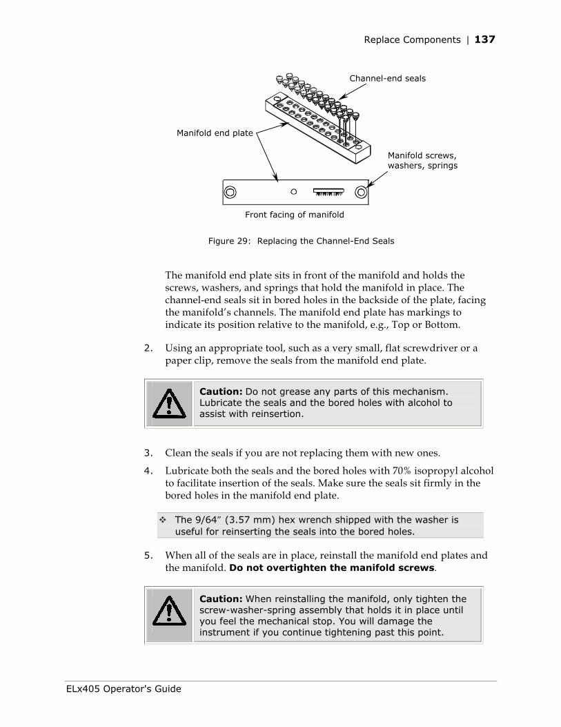
Replace Components | 137
Manifold end plate
Channel-end seals
Manifold screws, washers, springs
Front facing of manifold
Figure 29: Replacing the Channel-End Seals
The manifold end plate sits in front of the manifold and holds the screws, washers, and springs that hold the manifold in place. The channel-end seals sit in bored holes in the backside of the plate, facing the manifold’s channels. The manifold end plate has markings to indicate its position relative to the manifold, e.g., Top or Bottom.
2. Using an appropriate tool, such as a very small, flat screwdriver or a paper clip, remove the seals from the manifold end plate.
Caution: Do not grease any parts of this mechanism. Lubricate the seals and the bored holes with alcohol to assist with reinsertion.
3. Clean the seals if you are not replacing them with new ones.
4. Lubricate both the seals and the bored holes with 70% isopropyl alcohol to facilitate insertion of the seals. Make sure the seals sit firmly in the bored holes in the manifold end plate.
The 9/64” (3.57 mm) hex wrench shipped with the washer is useful for reinserting the seals into the bored holes.
5. When all of the seals are in place, reinstall the manifold end plates and the manifold. Do not overtighten the manifold screws.
Caution: When reinstalling the manifold, only tighten the screw-washer-spring assembly that holds it in place until you feel the mechanical stop. You will damage the instrument if you continue tightening past this point.
ELx405 Operator's Guide

138 | Chapter 4: Preventive Maintenance
Bio-Tek Instruments, Inc.
Chapter 5
Performance Verification/ Qualification Tests
This chapter describes how to verify the performance of the ELx405 Microplate Washer.
Overview................................................................................140 Verification Schedule................................................................141 Installation Qualification (IQ).....................................................142 Operational Qualification (OQ) ...................................................142 Performance Qualification (PQ) ..................................................143 System and Checksum Tests .....................................................144 Liquid Tests ............................................................................146
140 | Chapter 5: Performance Verification/Qualification Tests
Overview
Instrument verification for the ELx405 involves three activities: qualification of installation and setup, qualification of routine capability, and qualification of long-term stability. This chapter refers to these activities as Installation Qualification (IQ), Operational Qualification (OQ), and Performance Qualification (PQ), respectively.
Verification testing of the washer includes the System Self Test and Checksum Test, and liquid testing for Evacuation Efficiency and Dispense Precision. For washers equipped with the optional valve module, instrument verification includes Dispense Precision tests for the valve module.
• The System Self Test verifies system components, such as the vacuum, manifold, and carrier positioning. The Checksum Test verifies the basecode software against internal checksum values to ensure that no corruption has occurred. If the Checksum Test is run manually, part number and version information is displayed for the software on the instrument.
• Evacuation Efficiency. This test measures the residual volume per well after the aspiration aspect of plate washing. The lower the residuals per well, the better the evacuation efficiency of the washer.
• Dispense Precision. This test measures the variability of volumes dispensed from tube to tube across the manifold.
• Dispense Precision, Valve Module. The Dispense Precision Test for the external valve module measures the variability of volumes dispensed from tube to tube across the manifold, when the washer is used with the valve module.
The Ultrasonic Advantage™ (ultrasonic cleaner) does not require qualification testing.
Bio-Tek Instruments, Inc.
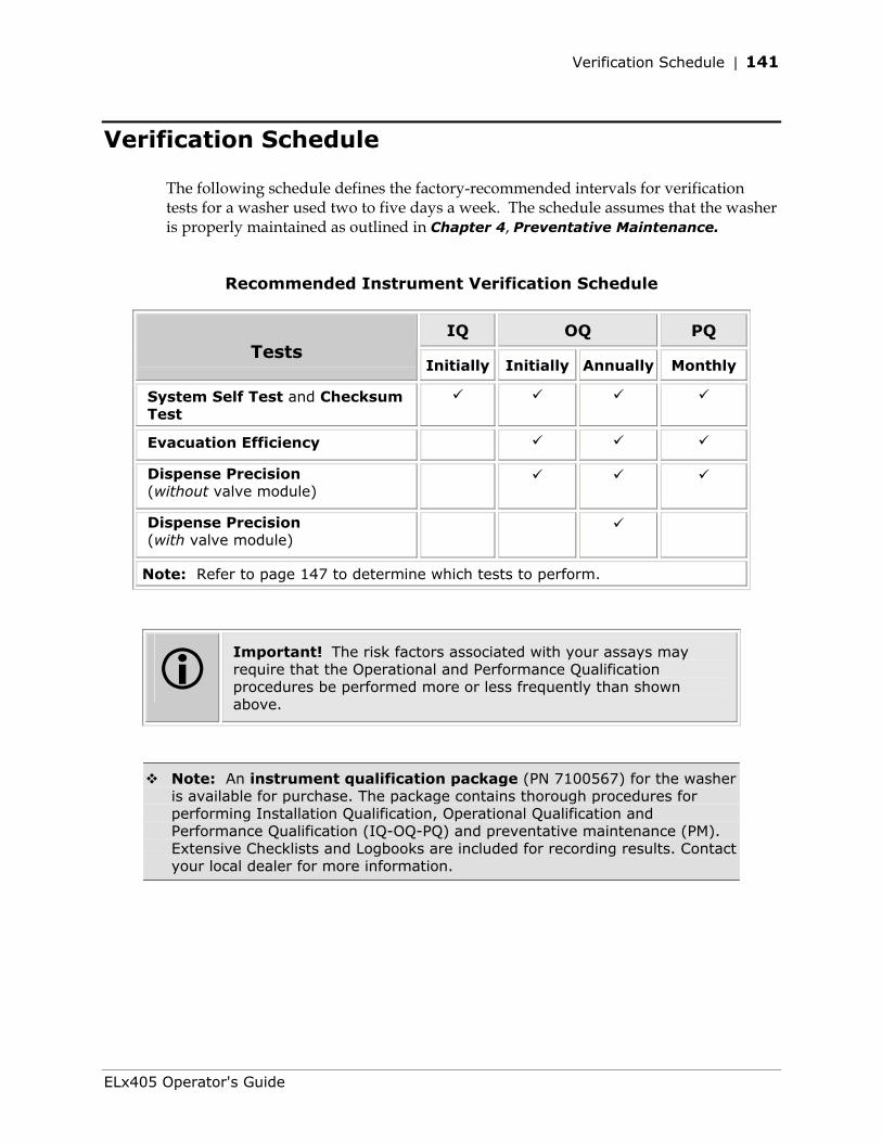
Verification Schedule | 141
Verification Schedule
The following schedule defines the factory-recommended intervals for verification tests for a washer used two to five days a week. The schedule assumes that the washer is properly maintained as outlined in Chapter 4, Preventative Maintenance.
Recommended Instrument Verification Schedule
IQ OQ PQ Tests
Initially Initially Annually Monthly
System Self Test and Checksum Test
Evacuation Efficiency
Dispense Precision (without valve module)
Dispense Precision (with valve module)
Note: Refer to page 147 to determine which tests to perform.
Important! The risk factors associated with your assays may require that the Operational and Performance Qualification procedures be performed more or less frequently than shown above.
Note: An instrument qualification package (PN 7100567) for the washer is available for purchase. The package contains thorough procedures for performing Installation Qualification, Operational Qualification and Performance Qualification (IQ-OQ-PQ) and preventative maintenance (PM). Extensive Checklists and Logbooks are included for recording results. Contact your local dealer for more information.
ELx405 Operator's Guide
142 | Chapter 5: Performance Verification/Qualification Tests
Installation Qualification (IQ)
Installation Qualification confirms that the washer and its components have been supplied as ordered and ensures that they are assembled and configured properly for your lab environment.
• The recommended IQ procedure consists of setting up the instrument as described in Chapter 2, Installation and then performing the System Self-Test and the Checksum test.
• The IQ procedure should be performed initially (before the washer is used for the first time).
• The successful completion of the IQ procedure verifies that the instrument is installed correctly. The Operational Qualification procedure should be performed immediately following the successful IQ (see below).
Operational Qualification (OQ)
Operational Qualification confirms that the washer operates according to specification initially and over time.
• The recommended OQ procedure consists of performing the System Self-Test and the Checksum, Evacuation Efficiency, and Dispense Precision tests.
• Your facility’s operating policies may also require that you perform an actual assay prior to accepting the washer for routine use. You should not use the data obtained from the first assay that utilizes the washer until you have confirmed that the package insert criteria have been met.
• The OQ procedure should be performed initially (before first use) and then routinely; the recommended interval is annually. It should also be performed after any major repair or upgrade to the hardware or software.
• Although out-of-tolerance failures will be detected by the OQ tests, results should be compared with those from the monthly Performance Qualification tests and previous OQ tests to monitor for trends.
• The successful completion of the OQ procedure, in combination with results that are comparable to previous PQ and OQ tests, confirms that the washer is performing consistently over time.
Bio-Tek Instruments, Inc.
Performance Qualification (PQ) | 143
Performance Qualification (PQ)
Performance Qualification confirms that the washer consistently meets the requirements of the tests performed at your laboratory.
• The recommended PQ procedure consists of performing the System Self-Test and the Checksum, Evacuation Efficiency, and Dispense Precision tests.
• Your facility’s operating policies may also require that you routinely perform an actual assay, to confirm that the washer will consistently give adequate results for the assays to be run with it.
• These tests should be performed routinely; the recommended interval is monthly. This frequency may be adjusted depending on the trends observed over time.
• The successful completion of the PQ procedure confirms that the washer is performing consistently under normal operating conditions.
ELx405 Operator's Guide
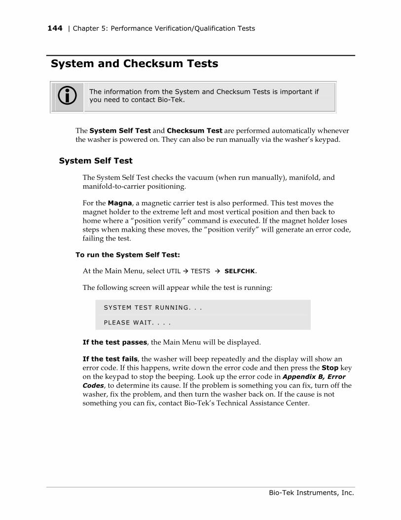
144 | Chapter 5: Performance Verification/Qualification Tests
System and Checksum Tests
The information from the System and Checksum Tests is important if you need to contact Bio-Tek.
The System Self Test and Checksum Test are performed automatically whenever the washer is powered on. They can also be run manually via the washer’s keypad.
System Self Test
The System Self Test checks the vacuum (when run manually), manifold, and manifold-to-carrier positioning.
For the Magna, a magnetic carrier test is also performed. This test moves the magnet holder to the extreme left and most vertical position and then back to home where a “position verify” command is executed. If the magnet holder loses steps when making these moves, the “position verify” will generate an error code, failing the test.
To run the System Self Test:
At the Main Menu, select UTIL TESTS SELFCHK.
The following screen will appear while the test is running:
SYSTEM TEST RUNNING. . .
PLEASE WAIT. . . .
If the test passes, the Main Menu will be displayed.
If the test fails, the washer will beep repeatedly and the display will show an error code. If this happens, write down the error code and then press the Stop key on the keypad to stop the beeping. Look up the error code in Appendix B, Error Codes, to determine its cause. If the problem is something you can fix, turn off the washer, fix the problem, and then turn the washer back on. If the cause is not something you can fix, contact Bio-Tek’s Technical Assistance Center.
Bio-Tek Instruments, Inc.
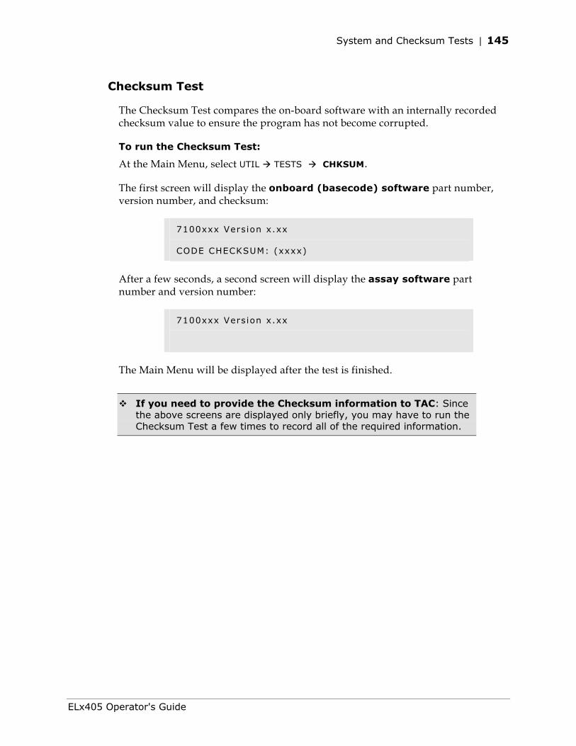
System and Checksum Tests | 145
Checksum Test
The Checksum Test compares the on-board software with an internally recorded checksum value to ensure the program has not become corrupted.
To run the Checksum Test: At the Main Menu, select UTIL TESTS CHKSUM.
The first screen will display the onboard (basecode) software part number, version number, and checksum:
7100xxx Version x.xx
CODE CHECKSUM: (xxxx)
After a few seconds, a second screen will display the assay software part number and version number:
7100xxx Version x.xx
The Main Menu will be displayed after the test is finished.
If you need to provide the Checksum information to TAC: Since the above screens are displayed only briefly, you may have to run the Checksum Test a few times to record all of the required information.
ELx405 Operator's Guide
146 | Chapter 5: Performance Verification/Qualification Tests
Liquid Tests
HT models with the accessory 96-tube manifold: Ensure that the washer is configured for operation with the correct manifold (96 or 192) (refer to Manifold Selection in Chapter 3, Operation). Failure to set the correct manifold type in the software before operating the washer may damage the manifold and void your warranty.
Evacuation Efficiency Test
The Evacuation Efficiency test measures the residual volume (mean residual weight) per well after the aspiration aspect of plate washing. The lower the residual per well, the better the evacuation efficiency of the washer.
A known solution is dispensed into all wells of a previously weighed microplate. The aspiration program is run and the plate is reweighed in order to calculate the total residual fluid based on the weight difference. The total residual fluid weight is divided by 96 or 384 as appropriate to obtain the mean residual weight.
If further testing is necessary (to identify “problem” wells), the supplemental test is performed. A concentrated dye solution is dispensed to/evacuated from the wells, and the plate is weighed. Buffer is then pipetted to all wells to bring the volume of fluid to a consistent measurement level. The optical density of each well is measured at 630 nm and the background at 450 nm is subtracted to account for scratches on the plate or particulates in a well. Each well’s residual volume is calculated using its optical density and a calibration factor derived from the mean residual weight and the mean optical density of all wells on the plate. It is assumed that 1 mg = 1 µl of fluid for this calculation.
Dispense Precision Test
The Dispense Precision Test measures the variability of the volumes dispensed from tube to tube across the manifold. In this test, a blue dye solution is dispensed into a microplate. The optical density of each well is measured at 630 nm and the background at 450 nm is subtracted to account for scratches on the plate or particulates in the well. The average error percentage is calculated and the amount dispensed to each well is calculated.
Acceptance is based on the %CV (%Coefficient of Variation), or the ratio of the standard deviation of the distribution of fluid volumes in the wells to the mean value of volume per well. The lower the %CV, the better the uniformity across the manifold.
Bio-Tek Instruments, Inc.
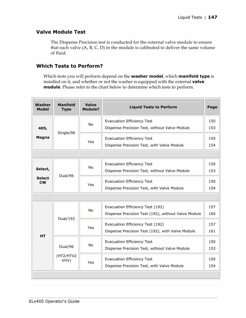
Liquid Tests | 147
Valve Module Test
The Dispense Precision test is conducted for the external valve module to ensure that each valve (A, B, C, D) in the module is calibrated to deliver the same volume of fluid.
Which Tests to Perform?
Which tests you will perform depend on the washer model, which manifold type is installed on it, and whether or not the washer is equipped with the external valve module. Please refer to the chart below to determine which tests to perform.
Washer Model
Manifold Type
Valve Module? Liquid Tests to Perform Page
No Evacuation Efficiency Test
Dispense Precision Test, without Valve Module
150
153 405,
Magna Single/96
Yes Evacuation Efficiency Test
Dispense Precision Test, with Valve Module
150
154
No Evacuation Efficiency Test
Dispense Precision Test, without Valve Module
150
153 Select,
Select CW
Dual/96
Yes Evacuation Efficiency Test
Dispense Precision Test, with Valve Module
150
154
No Evacuation Efficiency Test (192)
Dispense Precision Test (192), without Valve Module
157
160 Dual/192
Yes Evacuation Efficiency Test (192)
Dispense Precision Test (192), with Valve Module
157
161
No Evacuation Efficiency Test
Dispense Precision Test, without Valve Module
150
153
HT
Dual/96
(HT2/HTV2 only)
Yes Evacuation Efficiency Test
Dispense Precision Test, with Valve Module
150
154
ELx405 Operator's Guide
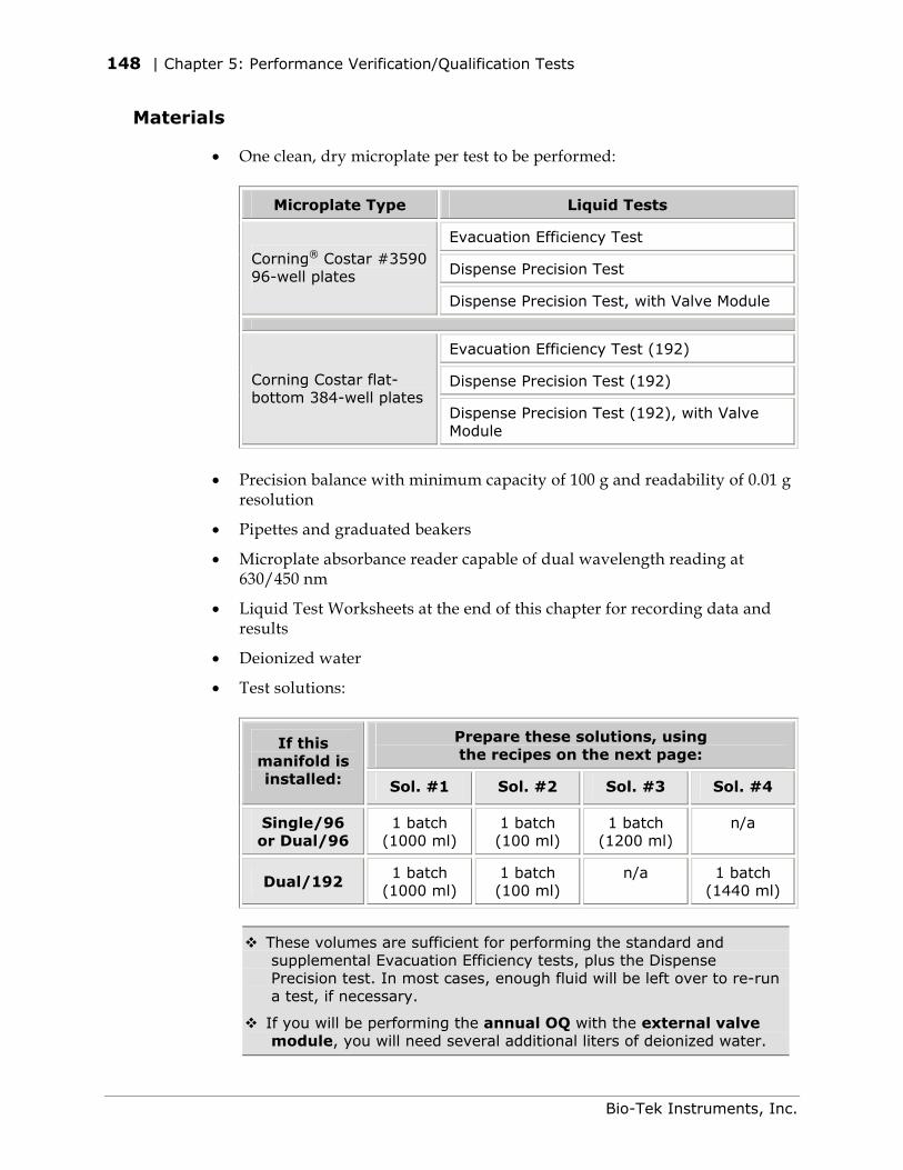
148 | Chapter 5: Performance Verification/Qualification Tests
Materials
• One clean, dry microplate per test to be performed:
Microplate Type Liquid Tests
Evacuation Efficiency Test
Dispense Precision Test Corning® Costar #3590 96-well plates
Dispense Precision Test, with Valve Module
Evacuation Efficiency Test (192)
Dispense Precision Test (192) Corning Costar flat-bottom 384-well plates
Dispense Precision Test (192), with Valve Module
• Precision balance with minimum capacity of 100 g and readability of 0.01 g
resolution
• Pipettes and graduated beakers
• Microplate absorbance reader capable of dual wavelength reading at 630/450 nm
• Liquid Test Worksheets at the end of this chapter for recording data and results
• Deionized water
• Test solutions:
Prepare these solutions, using the recipes on the next page:
If this manifold is installed: Sol. #1 Sol. #2 Sol. #3 Sol. #4
Single/96 or Dual/96
1 batch (1000 ml)
1 batch (100 ml)
1 batch (1200 ml)
n/a
Dual/192 1 batch
(1000 ml) 1 batch (100 ml)
n/a 1 batch (1440 ml)
These volumes are sufficient for performing the standard and supplemental Evacuation Efficiency tests, plus the Dispense Precision test. In most cases, enough fluid will be left over to re-run a test, if necessary.
If you will be performing the annual OQ with the external valve module, you will need several additional liters of deionized water.
Bio-Tek Instruments, Inc.
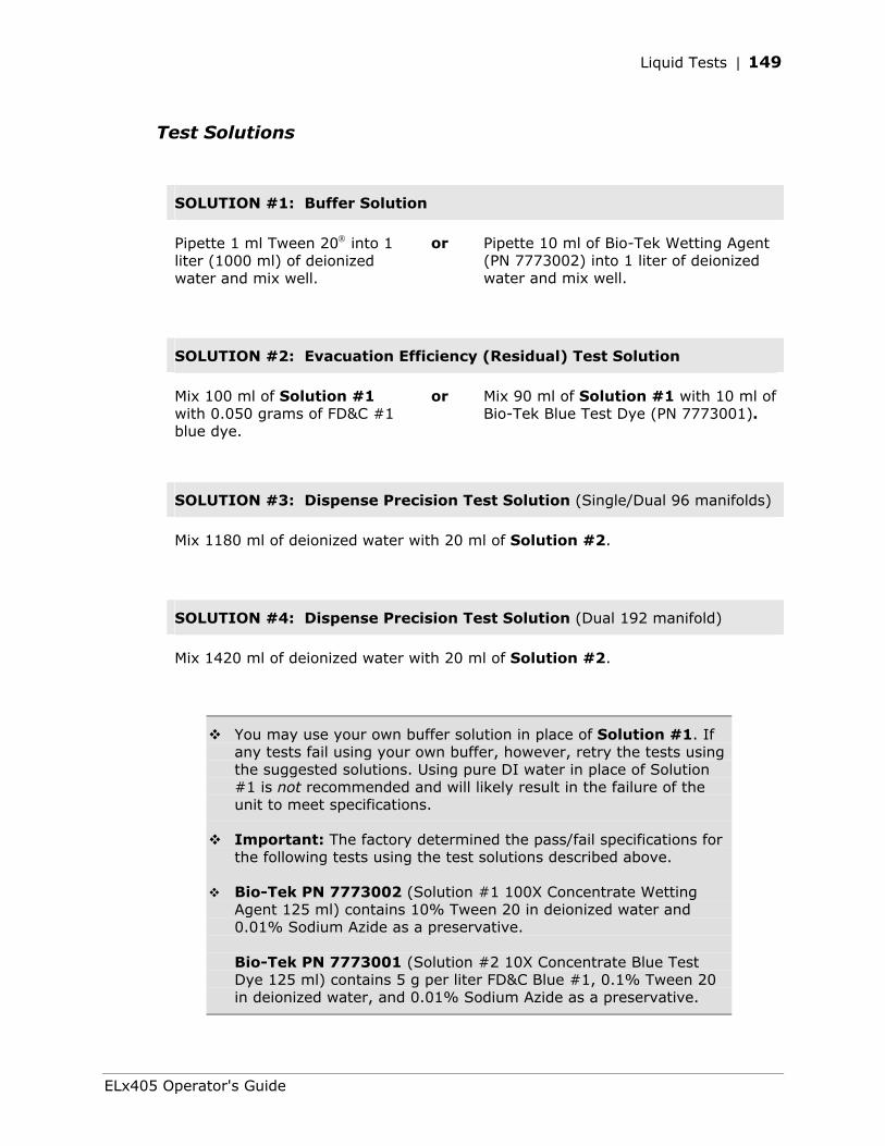
Liquid Tests | 149
Test Solutions
SOLUTION #1: Buffer Solution
Pipette 1 ml Tween 20 into 1 liter (1000 ml) of deionized water and mix well.
or Pipette 10 ml of Bio-Tek Wetting Agent (PN 7773002) into 1 liter of deionized water and mix well.
SOLUTION #2: Evacuation Efficiency (Residual) Test Solution
Mix 100 ml of Solution #1 with 0.050 grams of FD&C #1 blue dye.
or Mix 90 ml of Solution #1 with 10 ml of Bio-Tek Blue Test Dye (PN 7773001).
SOLUTION #3: Dispense Precision Test Solution (Single/Dual 96 manifolds)
Mix 1180 ml of deionized water with 20 ml of Solution #2.
SOLUTION #4: Dispense Precision Test Solution (Dual 192 manifold)
Mix 1420 ml of deionized water with 20 ml of Solution #2.
You may use your own buffer solution in place of Solution #1. If any tests fail using your own buffer, however, retry the tests using the suggested solutions. Using pure DI water in place of Solution #1 is not recommended and will likely result in the failure of the unit to meet specifications.
Important: The factory determined the pass/fail specifications for the following tests using the test solutions described above.
Bio-Tek PN 7773002 (Solution #1 100X Concentrate Wetting Agent 125 ml) contains 10% Tween 20 in deionized water and 0.01% Sodium Azide as a preservative. Bio-Tek PN 7773001 (Solution #2 10X Concentrate Blue Test Dye 125 ml) contains 5 g per liter FD&C Blue #1, 0.1% Tween 20 in deionized water, and 0.01% Sodium Azide as a preservative.
ELx405 Operator's Guide
150 | Chapter 5: Performance Verification/Qualification Tests
Evacuation Efficiency Test (96)
This test is designed for Single/96 or Dual/96 manifolds. See page 157 if you’re looking for the Evacuation Efficiency Test for the Dual/192 manifold.
See page 148 for a list of required materials.
1. Fill a supply bottle with two liters of deionized water. Run the Maintenance program DAY_RINSE two or three times to prime the fluid lines and manifold.
2. Place a clean, dry 96-well microplate on the balance and zero the balance.
3. Pipette or dispense 150 µl of Solution #1 into each well of the microplate.
4. Place the plate on the washer and run the Aspirate program residual_qc_test. This program evacuates all of the wells, leaving a small amount of residual fluid.
5. When the program is finished, remove the plate and weigh it immediately, because evaporation will affect the results. This is the Total Residual Weight, in grams.
6. Visually inspect the plate and note if any wells appear to have considerably more liquid in them than others.
7. Using the Evacuation Efficiency Test Worksheet on page 164, perform initial data reduction:
a. Divide the Total Residual Weight by 96 to find the Mean Residual Weight.
b. The Mean Residual Weight should be <= 0.005 g.
If the Mean Residual Weight is greater than 0.005 g, or if one or more wells appear to have much more liquid than the others, the washer failed the test.
Troubleshoot as follows:
• If the test fails once: Failure of this test is commonly caused by improper aspiration tube placement within the wells, usually because a microplate other than the recommended Corning Costar® 96 was used.
Bio-Tek Instruments, Inc.
Liquid Tests | 151
If you prefer to use a plate other than the Corning Costar 96, modifying the ASPIRATE HEIGHT or HORIZONTAL ASPIRATE POSITION parameters in a copy of the residual_qc_test program should correct this error (residual_qc_test is locked for editing, but you can copy the program and edit its parameters in the newly created copy). See Chapter 3, Operation, for instructions on copying and editing programs and modifying the abovementioned parameters. After making this change, retry the test using a clean, dry microplate.
If you are using the Corning Costar 96 microplate, run AUTOCLEAN (Ultrasonic Advantage™ models only), and/or remove the manifold and clean the aspiration tubes with the stylus (all models). See Chapter 4, Preventive Maintenance for complete instructions. When finished, retry the test using a clean, dry microplate.
• If the test fails a second time: Perform the Supplemental Test below.
Supplemental Test
Conduct this test if the Standard Evacuation Efficiency Test fails twice. This test will confirm which aspirate tube(s) may be clogged, or if the plate’s alignment or position is the problem.
1. Repeat steps 2 through 7 of the previous test, using Solution #2 for the dispense fluid. Be sure to recalculate the Mean Residual Weight.
2. Pipette 300 µl of Solution #1 into each well, on top of the residual solution.
3. Shake the plate to get uniform distribution of the remaining dye in each well.
If you are using one of Bio-Tek’s keypad-based readers, such as the ELx800 or ELx808, ensure that the reader is not running in Rapid mode. To check the setting, select UTIL READ and cycle through the options until READ IN RAPID MODE? appears. Set it to NO.
4. Read the plate in an optical reader (blank on air), using the dual-wavelength method (630 nm - 450 nm), then print or export the results.
5. Using the Evacuation Efficiency Test Worksheet on page 164, perform data reduction:
a. Calculate the sum of the OD values for all 96 wells, then divide by 96 to determine the Mean OD for the plate.
b. Divide the Mean OD by the Mean Residual Weight (from step 1), to find the Residual Factor.
ELx405 Operator's Guide
152 | Chapter 5: Performance Verification/Qualification Tests
c. For each well, divide its OD value by the Residual Factor to find its Residual Weight.
Each well’s Residual Weight should be <= 0.005 g.
If one or more wells has a Residual Weight greater than 0.005 g, review the data to determine which well, or wells, is causing the problem.
If the problem appears to be related to particular wells, clean the associated aspiration tubes: run AUTOCLEAN (Ultrasonic Advantage™ models only), and/or remove the manifold and thoroughly clean the tubes with the stylus (all models). See Chapter 4, Preventive Maintenance for complete instructions. When finished, retry the test.
If the problem appears to be related to a particular region, edge, or corner of the plate, review the alignment and flatness of the plate on the carrier.
Please do not adjust the carrier adjustment screws! Contact your Bio-Tek dealer if you suspect an alignment problem.
For additional suggestions, see Appendix A, Troubleshooting.
If the test continues to fail, contact Bio-Tek Instruments.
Bio-Tek Instruments, Inc.
Liquid Tests | 153
Dispense Precision Test (96)
This test is designed for Single/96 and Dual/96 manifolds. See page 160 if you’re looking for the Dispense Precision Test for the Dual/192 manifold.
See page 148 for a list of required materials.
Without the Valve Module
1. Fill a supply bottle with two liters of deionized water. Run the Prime program P_DAY_RINSE two or three times to prime the fluid lines and manifold.
2. Fill a supply bottle with 1200 ml of Solution #3.
3. Run P_DAY_RINSE to prime the washer with the solution.
4. Place a clean, dry 96-well microplate on the washer and run the Dispense program accuracy_qc_test. This program dispenses 300 µl of solution to each well of the plate. It does not evacuate the solution.
5. When the program is finished, carefully remove the plate.
If you are using one of Bio-Tek’s keypad-based readers, such as the ELx800 or ELx808, ensure that the reader is not running in Rapid mode. To check the setting, select UTIL READ and cycle through the options until READ IN RAPID MODE? appears. Set it to NO.
6. Read the plate in an optical reader (blank on air), using the dual-wavelength method (630 nm - 450 nm), then print or export the results.
7. Using the Dispense Precision Test Worksheet on page 165, perform data reduction:
a. Calculate the Standard Deviation.
Tip: If you have a spreadsheet software program, enter/export all 96 values into a spreadsheet and apply your program’s Standard Deviation function (e.g., Microsoft Excel’s STDEV).
b. Calculate the sum of the OD values for all 96 wells, then divide by 96 to determine the Mean OD for the plate.
c. Calculate the %CV: (Standard Deviation / Mean OD) * 100.
The %CV should be <= 4.0.
ELx405 Operator's Guide
154 | Chapter 5: Performance Verification/Qualification Tests
If the %CV is greater than 4.0, one or more dispense tubes may need to be cleaned. Run AUTOCLEAN (Ultrasonic Advantage™ models only), and/or remove the manifold and use the stylus to clean the dispense tube(s) giving lower-than-average absorbance readings (all models). When finished, re-prime the washer and retry the test.
8. When finished, prime with deionized water to flush out the dye solution.
With the Valve Module
Routine Procedure for Valve A
Perform this test during the initial/annual OQ, and the monthly PQ.
1. Fill the supply bottle for Valve A with two liters of deionized water. Run the Maintenance program DAY_RINSE two or three times to prime the fluid lines and the manifold.
2. Fill the supply bottle for Valve A with 1200 ml of Solution #3.
3. Run DAY_RINSE to prime Valve A with the solution.
4. Place a clean, dry 96-well microplate on the washer and run the Dispense program accuracy_qc_test. This program dispenses 300 µl of solution to each well of the plate. It does not evacuate the solution.
5. When the program is finished, carefully remove the plate.
If you are using one of Bio-Tek’s keypad-based readers, such as the ELx800 or ELx808, ensure that the reader is not running in Rapid mode. To check the setting, select UTIL READ and cycle through the options until READ IN RAPID MODE? appears. Set it to NO.
6. Read the plate in an optical reader (blank on air), using the dual-wavelength method (630 nm – 450 nm), then print or export the results.
7. Using the Dispense Precision Test Worksheet on page 166, perform data reduction:
a. Calculate the Standard Deviation.
Tip: If you have a spreadsheet program, enter/export all 96 values into a spreadsheet and apply your program’s Standard Deviation function (e.g., Microsoft Excel’s STDEV).
b. Calculate the sum of the OD values for all 96 wells, then divide by 96 to determine the Mean OD for the plate.
c. Calculate the %CV: (Standard Deviation / Mean OD) * 100.
The %CV should be <=4.0.
Bio-Tek Instruments, Inc.
Liquid Tests | 155
If the %CV is greater than 4.0, one or more dispense tubes may need to be cleaned. Run the AUTOCLEAN (Ultrasonic Advantage™ models only), and/or remove the manifold and use the stylus to clean the dispense tube(s) giving lower-than-average absorbance readings (all models). When finished, re-prime the washer and retry the test.
8. When finished, prime with deionized water to flush out the dye solution.
Annual Procedure for All Valves
Perform this test during the annual OQ only.
The routine test for Valve A (see previous page) must pass before the annual test for Valves A-D can be performed.
1. Empty the waste bottle now, and then as needed throughout this procedure.
2. Fill each of the supply bottles connected to Valves A, B, C, and D with three liters (3000 ml) of deionized water. Place the bottles on a surface level with the washer, i.e., the adjacent (lab bench) area.
Repeat the following steps for each valve:
3. Run the Maintenance program DAY_RINSE two or three times to prime the fluid lines, manifold, and the valve being tested.
ELx405 standard models (Single/96 manifold): See the note on the next page before performing step #4.
4. Edit the Dispense program accuracy_qc_test to use the Valve currently being tested (DEFINE EDIT DISP accuracy_qc_test).
5. Place a clean, dry 96-well microplate on the balance and zero the balance.
6. Place the microplate on the carrier and run the Dispense program accuracy_qc_test. This program dispenses 300 µl of water to each well of the plate. It does not evacuate the wells.
7. When the program is finished, carefully remove the plate and weigh it. This is the Total Dispense Weight in grams.
The weight should be 28.8 grams, ± 10% (between 25.92 g and 31.68 g).
If the weight falls outside this range, contact Bio-Tek.
ELx405 Operator's Guide
156 | Chapter 5: Performance Verification/Qualification Tests
If the weight falls below this range, the fluid inlet filter could be clogged, or the valve may be contaminated with fungi or proteins. See Cleaning the Fluid Inlet Filter in Chapter 4, Preventive Maintenance, for recommendations on cleaning the filter. The valve should be cleaned using an appropriate enzyme, alcohol, or a diluted bleach solution, depending on the contaminant. See Removing Protein Residuals and Fungi Growth and Decontamination in Chapter 4 for suggestions.
After cleaning the fluid inlet filter or valve and tubing, retry the test. If the test continues to fail, contact Bio-Tek.
8. Record the results in the Dispense Precision Test Worksheet on page 166.
For the ELx405™ standard model only, the accuracy_qc_test program is locked for editing; it can only be used to test Valve A. In order to test all four valves, you’ll need to create a copy of this program. You will then edit the copy when performing step #4.
To copy the test program:
Select DEFINE COPY DISP.
When accuracy_qc_test appears, press the Enter key.
When NAME: appears, use the keypad to enter an identifying name, such as ACC_QC_TEST.
Tip: Press Shift + a number key to type a letter. When the cursor is positioned under a letter, via the ► (forward) or ◄ (reverse) arrows, press the Options key to advance through the alphabet.
When finished entering the name, press the Enter key.
When OK TO COPY? appears, select YES.
Bio-Tek Instruments, Inc.
Liquid Tests | 157
Evacuation Efficiency Test (192)
This test is designed for the Dual/192 manifold. See page 150 if you’re looking for the Evacuation Efficiency Test for Single/96 and Dual/96 manifolds.
See page 148 for a list of required materials.
1. Fill a supply bottle with two liters of deionized water. Run the Maintenance program DAY_RINSE two or three times to prime the fluid lines and manifold.
2. Place a clean, dry 384-well microplate on the balance and zero the balance.
3. Pipette or dispense 80 µl of Solution #1 into each well of the microplate.
4. Place the plate on the washer and run the Aspirate program 192resid_qc_test. This program evacuates all of the wells, leaving a small amount of residual fluid.
5. When the program is finished, remove the plate and weigh it immediately, because evaporation will affect the results. This is the Total Residual Weight, in grams.
6. Visually inspect the plate and note if any wells appear to have considerably more liquid in them than others.
7. Using the Evacuation Efficiency Test Worksheet on page 167, perform initial data reduction:
a. Divide the Total Residual Weight by 384 to find the Mean Residual Weight.
b. The Mean Residual Weight should be <= 0.002 g.
If the Mean Residual Weight is greater than 0.002 g, or if one or more wells appear to have much more liquid than the others, the washer failed the test.
Troubleshoot as follows:
• If the test fails once: Failure of this test is most commonly caused by improper aspiration tube placement within the well, usually because a microplate other than the recommended Corning Costar® 384 was used.
If you prefer to use a plate other than the Corning Costar 384, modifying the ASPIRATE HEIGHT or HORIZONTAL ASPIRATE POSITION parameters in a copy of the 192resid_qc_test program should correct this error. (192resid_qc_test is locked for editing, but you can copy the program and edit its parameters in the newly created copy.) See Chapter 3, Operation, for instructions on copying and editing programs and modifying the abovementioned parameters. After making this change, retry the test using a clean, dry microplate.
ELx405 Operator's Guide
158 | Chapter 5: Performance Verification/Qualification Tests
If you are using the Corning Costar 384 microplate, run AUTOCLEAN (Ultrasonic Advantage™ models only), and/or remove the manifold and clean the aspiration tubes with the stylus (all models). See Chapter 4, Preventive Maintenance for complete instructions. When finished, retry the test using a clean, dry microplate.
• If the test fails a second time: Perform the Supplemental Test below.
Supplemental Test
Conduct this test if the Standard Evacuation Efficiency Test (192) fails twice. This test will confirm which aspirate tube(s) may be clogged, or if the plate’s alignment or position is the problem.
1. Repeat steps 2 through 7 of the previous test, using Solution #2 for the dispense fluid. Be sure to recalculate the Mean Residual Weight.
2. Pipette 80 µl of Solution #1 into each well, on top of the residual solution.
3. Shake the plate to get uniform distribution of the remaining dye in each well.
Note: If you are using one of Bio-Tek’s keypad-based readers, such as the ELx800NB, ensure that the reader is not running in Rapid Mode. To check the setting, select UTIL READ and cycle through the options until READ IN RAPID MODE? appears. Set it to NO.
4. Read the plate in an optical reader (blank on air), using the dual-wavelength method (630 nm - 450 nm), then print or export the results.
5. Using the Evacuation Efficiency Test Worksheet on page 167, perform data reduction:
a. Calculate the sum of the OD values for all 384 wells, then divide by 384 to determine the Mean OD for the plate.
b. Divide the Mean OD by the Mean Residual Weight (from step 1) to find the Residual Factor.
c. For each well, divide its OD value by the Residual Factor to find its Residual Weight.
Each well’s Residual Weight should be <= 0.002 g.
If one or more wells has a Residual Weight greater than 0.002 g, review the data to determine which well, or wells, is causing the problem.
Bio-Tek Instruments, Inc.
Liquid Tests | 159
If the problem appears to be related to particular wells, clean the associated aspiration tubes: run AUTOCLEAN (Ultrasonic Advantage™ models only), and/or remove the manifold and thoroughly clean the tubes with the stylus (all models). See Chapter 4, Preventive Maintenance for complete instructions. When finished, retry the test.
If the problem appears to be related to a particular region, edge, or corner of the plate, review the alignment and flatness of the plate on the carrier.
Please do not adjust the carrier adjustment screws! Contact your Bio-Tek dealer if you suspect an alignment problem.
For additional suggestions, refer to Appendix A, Troubleshooting.
If the test continues to fail, contact Bio-Tek Instruments.
ELx405 Operator's Guide
160 | Chapter 5: Performance Verification/Qualification Tests
Dispense Precision Test (192)
This test is designed for the Dual/192 manifold. See page 153 if you’re looking for the Dispense Precision Test for Single/96 and Dual/96 manifolds.
See page 148 for a list of required materials.
Without Valve Module
1. Fill a supply bottle with two liters of deionized water. Run the Prime program P_DAY_RINSE two or three times to prime the fluid lines and manifold.
2. Fill a supply bottle with 1440 ml of Solution #4.
3. Run P_DAY_RINSE to prime the washer with the solution.
4. Place a clean, dry 384-well microplate on the washer and run the Dispense program 192accuracy_qc. This program dispenses 80 µl of solution to each well of the plate. It does not evacuate the solution.
5. When the program is finished, carefully remove the plate.
Note: If you are using one of Bio-Tek’s keypad-based readers, such as the ELx800NB, ensure that the reader is not running in Rapid Mode. To check the setting, select UTIL READ and cycle through the options until READ IN RAPID MODE? appears. Set it to NO.
6. Read the plate in an optical reader (blank on air), using the dual-wavelength method (630 nm - 450 nm), then print or export the results.
7. Using the appropriate Dispense Precision Test Worksheet on page 168, perform data reduction:
a. Calculate the Standard Deviation.
Tip: If you have a spreadsheet software program, enter/export all 384 values into a spreadsheet and apply your program’s Standard Deviation function (e.g., Microsoft Excel’s STDEV).
b. Calculate the sum of the OD values for all 384 wells, then divide by 384 to determine the Mean OD for the plate.
c. Calculate the %CV: (Standard Deviation / Mean OD) * 100.
The %CV should be <= 4.0.
Bio-Tek Instruments, Inc.
Liquid Tests | 161
If the %CV is greater than 4.0, one or more dispense tubes may need to be cleaned. Run AUTOCLEAN (Ultrasonic Advantage™ models only), and/or remove the manifold and use the stylus to clean the dispense tube(s) giving lower-than-average absorbance readings (all models). When finished, re-prime the washer and retry the test.
8. When finished, prime with deionized water to flush out the dye solution.
With the Valve Module
Routine Procedure for Valve A
Perform this test during the initial/annual OQ, and the monthly PQ.
1. Fill the supply bottle for Valve A with two liters of deionized water. Run the Maintenance program DAY_RINSE two or three times to prime the fluid lines and the manifold.
2. Fill the supply bottle for Valve A with 1440 ml of Solution #4.
3. Run DAY_RINSE to prime Valve A with the solution.
4. Place a clean, dry 384-well microplate on the washer and run the Dispense program 192accuracy_qc. This program dispenses 80 µl of solution to each well of the plate. It does not evacuate the solution.
5. When the program is finished, carefully remove the plate.
Note: If you are using one of Bio-Tek’s keypad-based readers, such as the ELx800NB, ensure that the reader is not running in Rapid Mode. To check the setting, select UTIL READ and cycle through the options until READ IN RAPID MODE? appears. Set it to NO.
6. Read the plate in an optical reader (blank on air), using the dual-wavelength method (630 nm - 450 nm), then print or export the results.
7. Using the Dispense Precision Test Worksheet on page 169, perform data reduction:
a. Calculate the Standard Deviation.
Tip: If you have a spreadsheet software program, enter/export all 384 values into a spreadsheet and apply your program’s Standard Deviation function (e.g., Microsoft Excel’s STDEV).
b. Calculate the sum of the OD values for all 384 wells, then divide by 384 to determine the Mean OD for the plate.
ELx405 Operator's Guide
162 | Chapter 5: Performance Verification/Qualification Tests
c. Calculate the %CV: (Standard Deviation / Mean OD) * 100.
The %CV should be <= 4.0.
8. If the %CV is greater than 4.0, one or more dispense tubes may need to be cleaned. Run AUTOCLEAN (Ultrasonic Advantage™ models only), and/or remove the manifold and use the stylus to clean the dispense tube(s) giving lower-than-average absorbance readings (all models). When finished, re-prime the washer and retry the test.
9. When finished, prime with deionized water to flush out the dye solution.
Annual Procedure for All Valves
Perform this test during the annual OQ only.
The routine test for Valve A must pass before the annual test for Valves A-D can be performed.
1. Empty the waste bottle now, and then as needed throughout this procedure.
2. Fill each of the supply bottles connected to Valves A, B, C, and D with three liters (3000 ml) of deionized water.
Repeat the following steps for each valve:
3. Run the Maintenance program DAY_RINSE two or three times to prime the fluid lines, manifold, and the valve being tested.
4. Edit the Dispense program 192accuracy_qc to use the Valve currently being tested (DEFINE EDIT DISP 192accuracy_qc).
5. Place a clean, dry 384-well microplate on the balance and zero the balance.
6. Place the microplate on the washer and run the Dispense program 192accuracy_qc. This program dispenses 80 µl of water to each well of the plate. It does not evacuate the wells.
7. When the program is finished, carefully remove the plate and weigh it. This is the Total Dispense Weight in grams.
The weight should be 30.72 grams, ± 10% (between 27.65 g and 33.79 g).
If the weight falls outside this range, contact Bio-Tek.
Bio-Tek Instruments, Inc.
Liquid Tests | 163
If the weight falls below this range, the fluid inlet filter could be clogged, or the valve may be contaminated with fungi or proteins. See Cleaning the Fluid Inlet Filter in Chapter 4, Preventive Maintenance, for recommendations on cleaning the filter. The valve should be cleaned using an appropriate enzyme, alcohol, or a diluted bleach solution, depending on the contaminant. See Removing Protein Residuals and Fungi Growth and Decontamination in Chapter 4 for suggestions.
After cleaning the fluid inlet filter or valve and tubing, retry the test. If the test continues to fail, contact Bio-Tek.
8. Record results in the Dispense Precision Test Worksheet on page 169.
ELx405 Operator's Guide
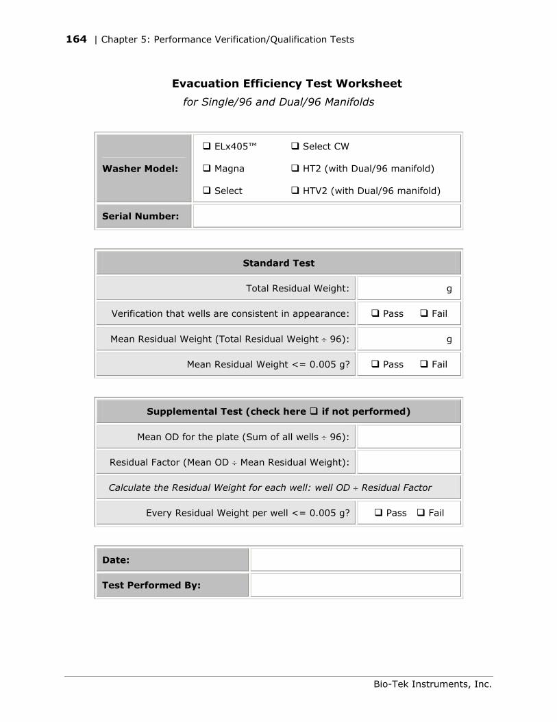
164 | Chapter 5: Performance Verification/Qualification Tests
Evacuation Efficiency Test Worksheet
for Single/96 and Dual/96 Manifolds
Washer Model:
ELx405™ Select CW
Magna HT2 (with Dual/96 manifold)
Select HTV2 (with Dual/96 manifold)
Serial Number:
Standard Test
Total Residual Weight: g
Verification that wells are consistent in appearance: Pass Fail
Mean Residual Weight (Total Residual Weight ÷ 96): g
Mean Residual Weight <= 0.005 g? Pass Fail
Supplemental Test (check here if not performed)
Mean OD for the plate (Sum of all wells ÷ 96):
Residual Factor (Mean OD ÷ Mean Residual Weight):
Calculate the Residual Weight for each well: well OD ÷ Residual Factor
Every Residual Weight per well <= 0.005 g? Pass Fail
Date:
Test Performed By:
Bio-Tek Instruments, Inc.
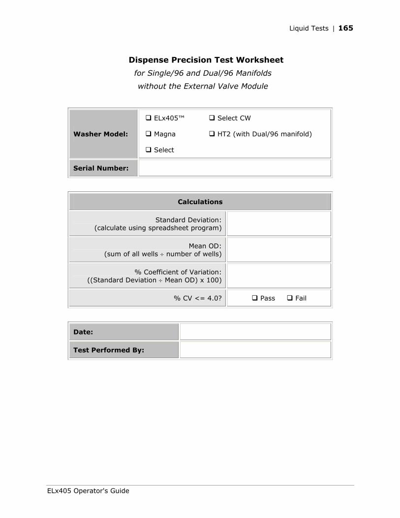
Liquid Tests | 165
Dispense Precision Test Worksheet
for Single/96 and Dual/96 Manifolds
without the External Valve Module
Washer Model:
ELx405™ Select CW
Magna HT2 (with Dual/96 manifold)
Select
Serial Number:
Calculations
Standard Deviation: (calculate using spreadsheet program)
Mean OD: (sum of all wells ÷ number of wells)
% Coefficient of Variation: ((Standard Deviation ÷ Mean OD) x 100)
% CV <= 4.0? Pass Fail
Date:
Test Performed By:
ELx405 Operator's Guide
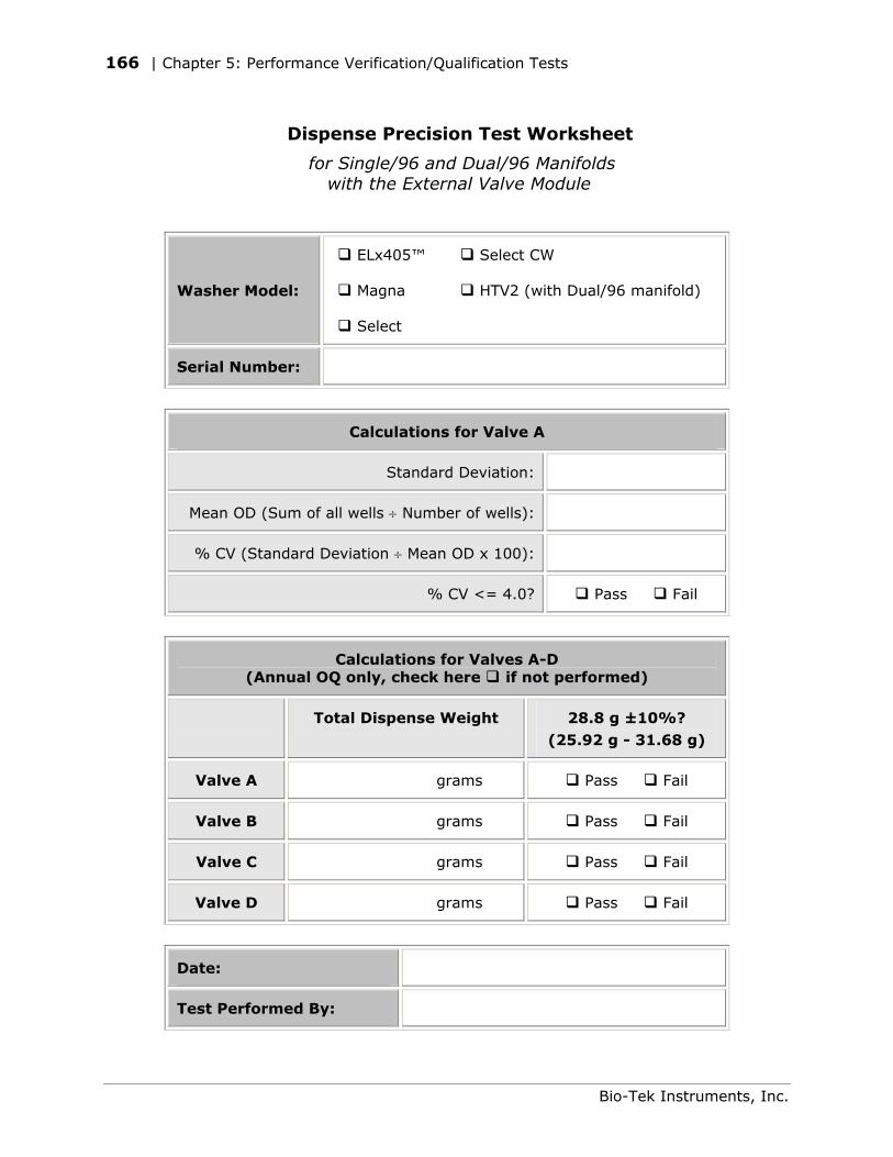
166 | Chapter 5: Performance Verification/Qualification Tests
Dispense Precision Test Worksheet
for Single/96 and Dual/96 Manifolds with the External Valve Module
Washer Model:
ELx405™ Select CW
Magna HTV2 (with Dual/96 manifold)
Select
Serial Number:
Calculations for Valve A
Standard Deviation:
Mean OD (Sum of all wells ÷ Number of wells):
% CV (Standard Deviation ÷ Mean OD x 100):
% CV <= 4.0? Pass Fail
Calculations for Valves A-D (Annual OQ only, check here if not performed)
Total Dispense Weight 28.8 g ±10%? (25.92 g - 31.68 g)
Valve A grams Pass Fail
Valve B grams Pass Fail
Valve C grams Pass Fail
Valve D grams Pass Fail
Date:
Test Performed By:
Bio-Tek Instruments, Inc.
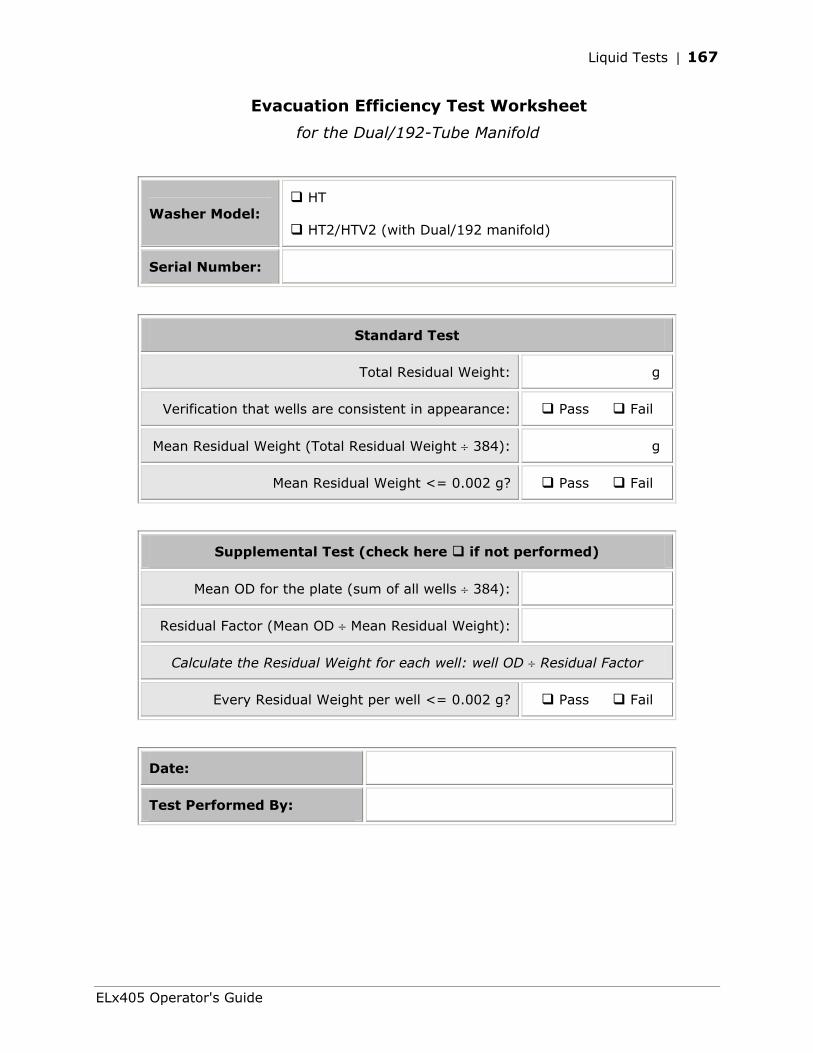
Liquid Tests | 167
Evacuation Efficiency Test Worksheet
for the Dual/192-Tube Manifold
Washer Model: HT
HT2/HTV2 (with Dual/192 manifold)
Serial Number:
Standard Test
Total Residual Weight: g
Verification that wells are consistent in appearance: Pass Fail
Mean Residual Weight (Total Residual Weight ÷ 384): g
Mean Residual Weight <= 0.002 g? Pass Fail
Supplemental Test (check here if not performed)
Mean OD for the plate (sum of all wells ÷ 384):
Residual Factor (Mean OD ÷ Mean Residual Weight):
Calculate the Residual Weight for each well: well OD ÷ Residual Factor
Every Residual Weight per well <= 0.002 g? Pass Fail
Date:
Test Performed By:
ELx405 Operator's Guide
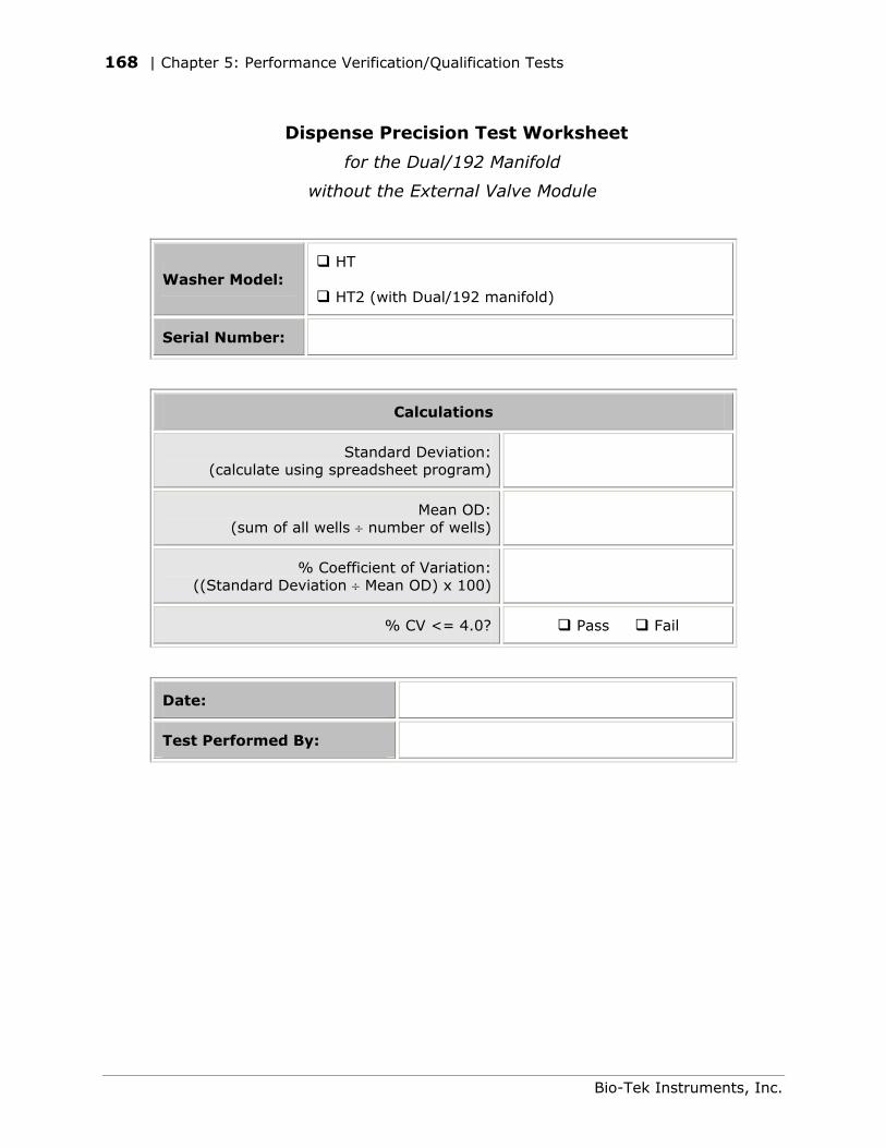
168 | Chapter 5: Performance Verification/Qualification Tests
Dispense Precision Test Worksheet
for the Dual/192 Manifold
without the External Valve Module
Washer Model: HT
HT2 (with Dual/192 manifold)
Serial Number:
Calculations
Standard Deviation: (calculate using spreadsheet program)
Mean OD: (sum of all wells ÷ number of wells)
% Coefficient of Variation: ((Standard Deviation ÷ Mean OD) x 100)
% CV <= 4.0? Pass Fail
Date:
Test Performed By:
Bio-Tek Instruments, Inc.
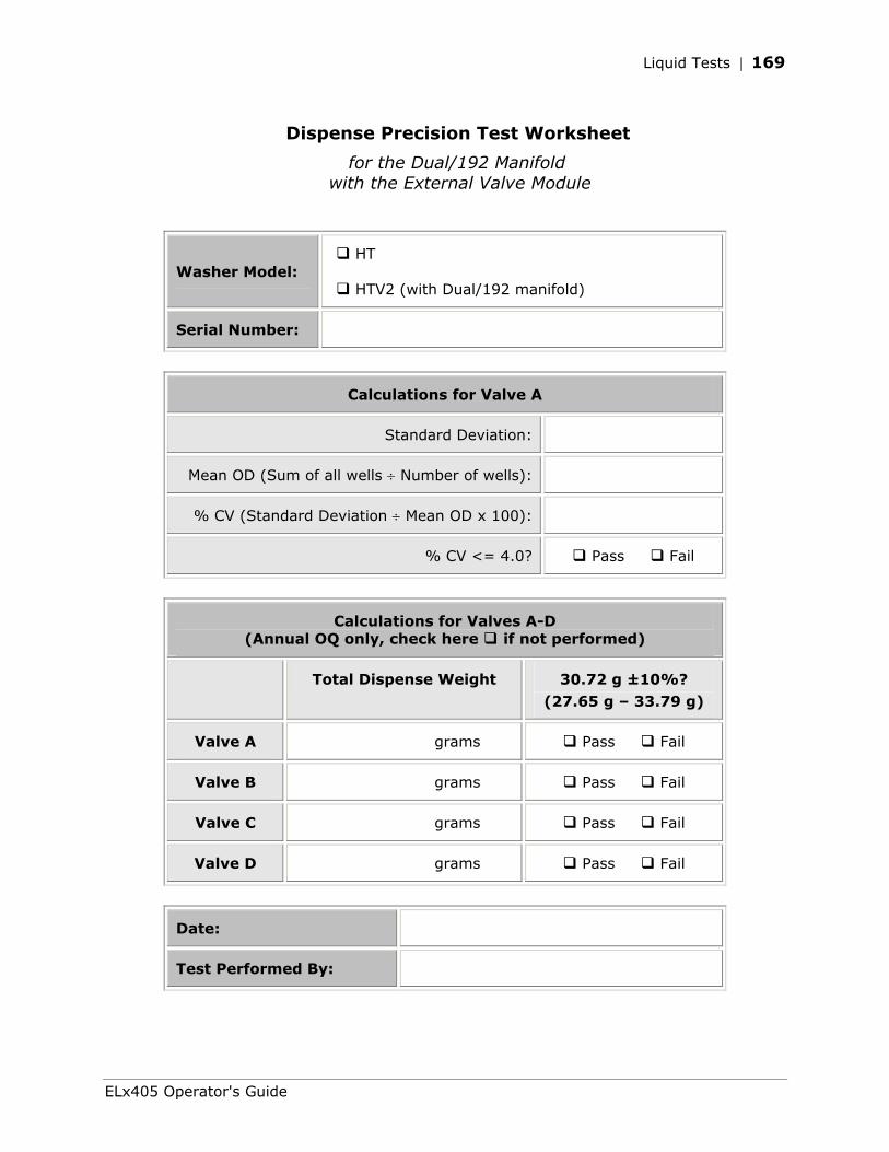
Liquid Tests | 169
Dispense Precision Test Worksheet
for the Dual/192 Manifold with the External Valve Module
Washer Model: HT
HTV2 (with Dual/192 manifold)
Serial Number:
Calculations for Valve A
Standard Deviation:
Mean OD (Sum of all wells ÷ Number of wells):
% CV (Standard Deviation ÷ Mean OD x 100):
% CV <= 4.0? Pass Fail
Calculations for Valves A-D (Annual OQ only, check here if not performed)
Total Dispense Weight 30.72 g ±10%? (27.65 g – 33.79 g)
Valve A grams Pass Fail
Valve B grams Pass Fail
Valve C grams Pass Fail
Valve D grams Pass Fail
Date:
Test Performed By:
ELx405 Operator's Guide
170 | Chapter 5: Performance Verification/Qualification Tests
Bio-Tek Instruments, Inc.
Appendix A
Troubleshooting
This appendix lists problems that you may experience with the washer, and suggests possible solutions for these problems.
Overview................................................................................172 Troubleshooting Charts.............................................................173
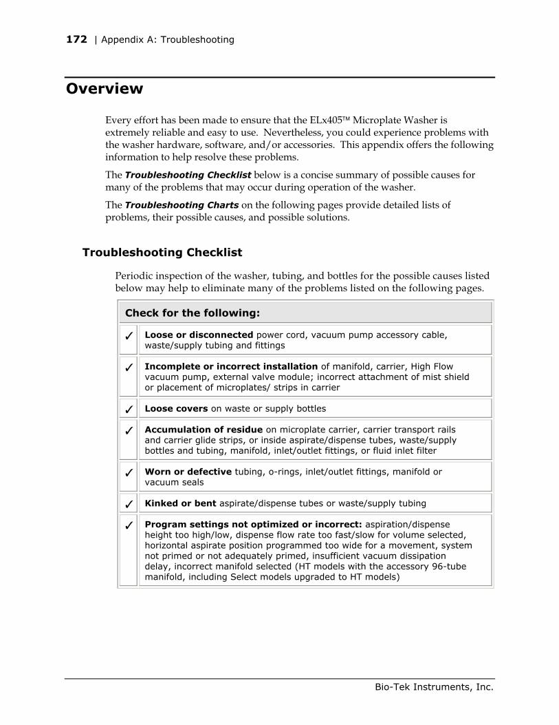
172 | Appendix A: Troubleshooting
Overview
Every effort has been made to ensure that the ELx405 Microplate Washer is extremely reliable and easy to use. Nevertheless, you could experience problems with the washer hardware, software, and/or accessories. This appendix offers the following information to help resolve these problems.
The Troubleshooting Checklist below is a concise summary of possible causes for many of the problems that may occur during operation of the washer.
The Troubleshooting Charts on the following pages provide detailed lists of problems, their possible causes, and possible solutions.
Troubleshooting Checklist
Periodic inspection of the washer, tubing, and bottles for the possible causes listed below may help to eliminate many of the problems listed on the following pages.
Check for the following:
Loose or disconnected power cord, vacuum pump accessory cable, waste/supply tubing and fittings
Incomplete or incorrect installation of manifold, carrier, High Flow vacuum pump, external valve module; incorrect attachment of mist shield or placement of microplates/ strips in carrier
Loose covers on waste or supply bottles
Accumulation of residue on microplate carrier, carrier transport rails and carrier glide strips, or inside aspirate/dispense tubes, waste/supply bottles and tubing, manifold, inlet/outlet fittings, or fluid inlet filter
Worn or defective tubing, o-rings, inlet/outlet fittings, manifold or vacuum seals
Kinked or bent aspirate/dispense tubes or waste/supply tubing
Program settings not optimized or incorrect: aspiration/dispense height too high/low, dispense flow rate too fast/slow for volume selected, horizontal aspirate position programmed too wide for a movement, system not primed or not adequately primed, insufficient vacuum dissipation delay, incorrect manifold selected (HT models with the accessory 96-tube manifold, including Select models upgraded to HT models)
Bio-Tek Instruments, Inc.
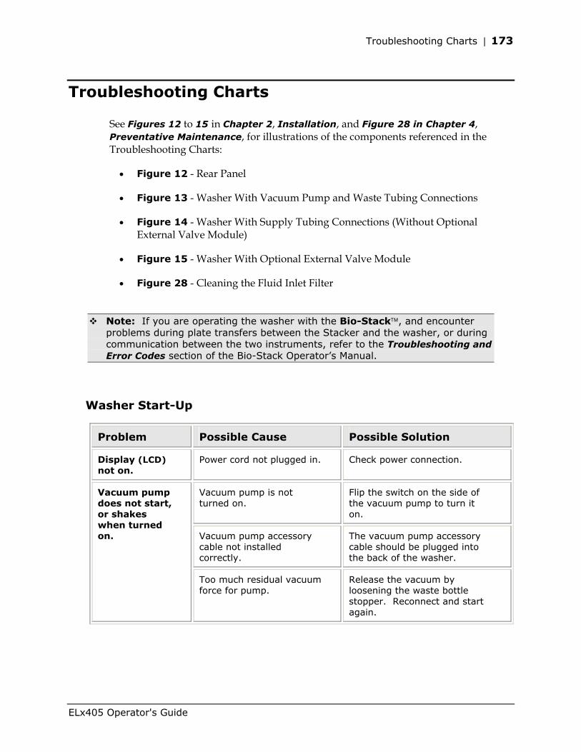
Troubleshooting Charts | 173
Troubleshooting Charts
See Figures 12 to 15 in Chapter 2, Installation, and Figure 28 in Chapter 4, Preventative Maintenance, for illustrations of the components referenced in the Troubleshooting Charts:
• Figure 12 - Rear Panel
• Figure 13 - Washer With Vacuum Pump and Waste Tubing Connections
• Figure 14 - Washer With Supply Tubing Connections (Without Optional External Valve Module)
• Figure 15 - Washer With Optional External Valve Module
• Figure 28 - Cleaning the Fluid Inlet Filter
Note: If you are operating the washer with the Bio-Stack, and encounter problems during plate transfers between the Stacker and the washer, or during communication between the two instruments, refer to the Troubleshooting and Error Codes section of the Bio-Stack Operator’s Manual.
Washer Start-Up
Problem Possible Cause Possible Solution
Display (LCD) not on.
Power cord not plugged in. Check power connection.
Vacuum pump is not turned on.
Flip the switch on the side of the vacuum pump to turn it on.
Vacuum pump accessory cable not installed correctly.
The vacuum pump accessory cable should be plugged into the back of the washer.
Vacuum pump does not start, or shakes when turned on.
Too much residual vacuum force for pump.
Release the vacuum by loosening the waste bottle stopper. Reconnect and start again.
ELx405 Operator's Guide
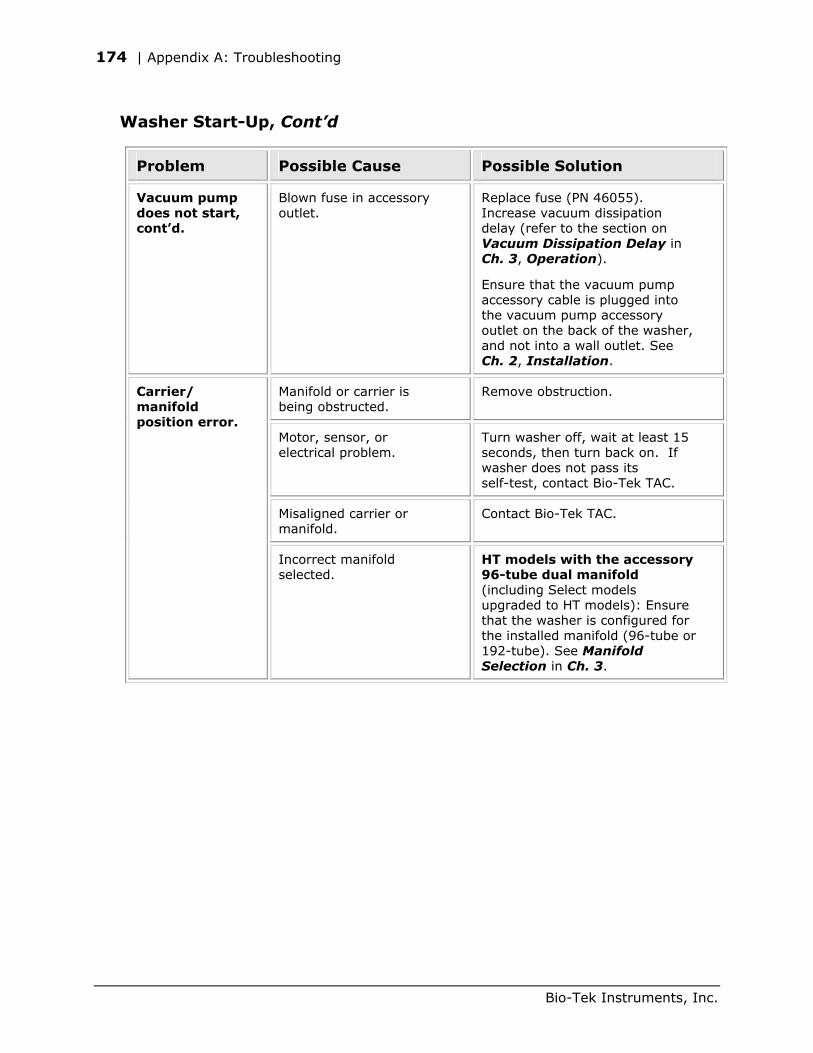
174 | Appendix A: Troubleshooting
Washer Start-Up, Cont’d
Problem Possible Cause Possible Solution
Vacuum pump does not start, cont’d.
Blown fuse in accessory outlet.
Replace fuse (PN 46055). Increase vacuum dissipation delay (refer to the section on Vacuum Dissipation Delay in Ch. 3, Operation).
Ensure that the vacuum pump accessory cable is plugged into the vacuum pump accessory outlet on the back of the washer, and not into a wall outlet. See Ch. 2, Installation.
Manifold or carrier is being obstructed.
Remove obstruction.
Motor, sensor, or electrical problem.
Turn washer off, wait at least 15 seconds, then turn back on. If washer does not pass its self-test, contact Bio-Tek TAC.
Misaligned carrier or manifold.
Contact Bio-Tek TAC.
Carrier/ manifold position error.
Incorrect manifold selected.
HT models with the accessory 96-tube dual manifold (including Select models upgraded to HT models): Ensure that the washer is configured for the installed manifold (96-tube or 192-tube). See Manifold Selection in Ch. 3.
Bio-Tek Instruments, Inc.
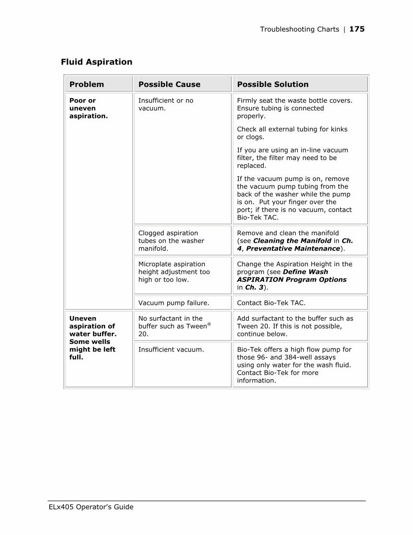
Troubleshooting Charts | 175
Fluid Aspiration
Problem Possible Cause Possible Solution
Insufficient or no vacuum.
Firmly seat the waste bottle covers. Ensure tubing is connected properly.
Check all external tubing for kinks or clogs.
If you are using an in-line vacuum filter, the filter may need to be replaced.
If the vacuum pump is on, remove the vacuum pump tubing from the back of the washer while the pump is on. Put your finger over the port; if there is no vacuum, contact Bio-Tek TAC.
Clogged aspiration tubes on the washer manifold.
Remove and clean the manifold (see Cleaning the Manifold in Ch. 4, Preventative Maintenance).
Microplate aspiration height adjustment too high or too low.
Change the Aspiration Height in the program (see Define Wash ASPIRATION Program Options in Ch. 3).
Poor or uneven aspiration.
Vacuum pump failure. Contact Bio-Tek TAC.
No surfactant in the buffer such as Tween® 20.
Add surfactant to the buffer such as Tween 20. If this is not possible, continue below.
Uneven aspiration of water buffer. Some wells might be left full.
Insufficient vacuum. Bio-Tek offers a high flow pump for those 96- and 384-well assays using only water for the wash fluid. Contact Bio-Tek for more information.
ELx405 Operator's Guide
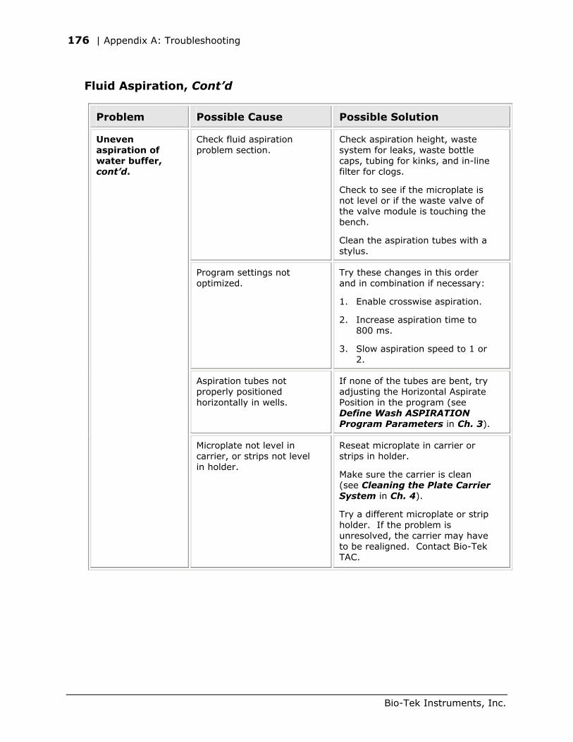
176 | Appendix A: Troubleshooting
Fluid Aspiration, Cont’d
Problem Possible Cause Possible Solution
Check fluid aspiration problem section.
Check aspiration height, waste system for leaks, waste bottle caps, tubing for kinks, and in-line filter for clogs.
Check to see if the microplate is not level or if the waste valve of the valve module is touching the bench.
Clean the aspiration tubes with a stylus.
Program settings not optimized.
Try these changes in this order and in combination if necessary:
1. Enable crosswise aspiration.
2. Increase aspiration time to 800 ms.
3. Slow aspiration speed to 1 or 2.
Aspiration tubes not properly positioned horizontally in wells.
If none of the tubes are bent, try adjusting the Horizontal Aspirate Position in the program (see Define Wash ASPIRATION Program Parameters in Ch. 3).
Uneven aspiration of water buffer, cont’d.
Microplate not level in carrier, or strips not level in holder.
Reseat microplate in carrier or strips in holder.
Make sure the carrier is clean (see Cleaning the Plate Carrier System in Ch. 4).
Try a different microplate or strip holder. If the problem is unresolved, the carrier may have to be realigned. Contact Bio-Tek TAC.
Bio-Tek Instruments, Inc.
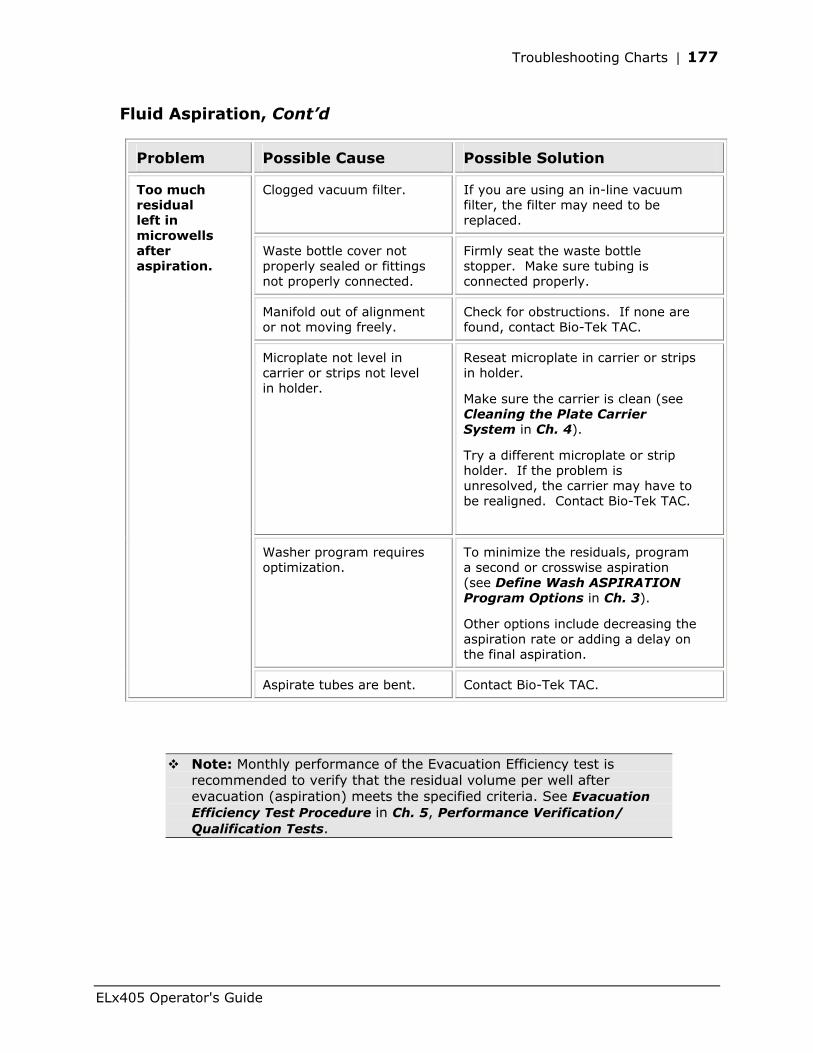
Troubleshooting Charts | 177
Fluid Aspiration, Cont’d
Problem Possible Cause Possible Solution
Clogged vacuum filter. If you are using an in-line vacuum filter, the filter may need to be replaced.
Waste bottle cover not properly sealed or fittings not properly connected.
Firmly seat the waste bottle stopper. Make sure tubing is connected properly.
Manifold out of alignment or not moving freely.
Check for obstructions. If none are found, contact Bio-Tek TAC.
Microplate not level in carrier or strips not level in holder.
Reseat microplate in carrier or strips in holder.
Make sure the carrier is clean (see Cleaning the Plate Carrier System in Ch. 4).
Try a different microplate or strip holder. If the problem is unresolved, the carrier may have to be realigned. Contact Bio-Tek TAC.
Washer program requires optimization.
To minimize the residuals, program a second or crosswise aspiration (see Define Wash ASPIRATION Program Options in Ch. 3).
Other options include decreasing the aspiration rate or adding a delay on the final aspiration.
Too much residual left in microwells after aspiration.
Aspirate tubes are bent. Contact Bio-Tek TAC.
Note: Monthly performance of the Evacuation Efficiency test is recommended to verify that the residual volume per well after evacuation (aspiration) meets the specified criteria. See Evacuation Efficiency Test Procedure in Ch. 5, Performance Verification/ Qualification Tests.
ELx405 Operator's Guide
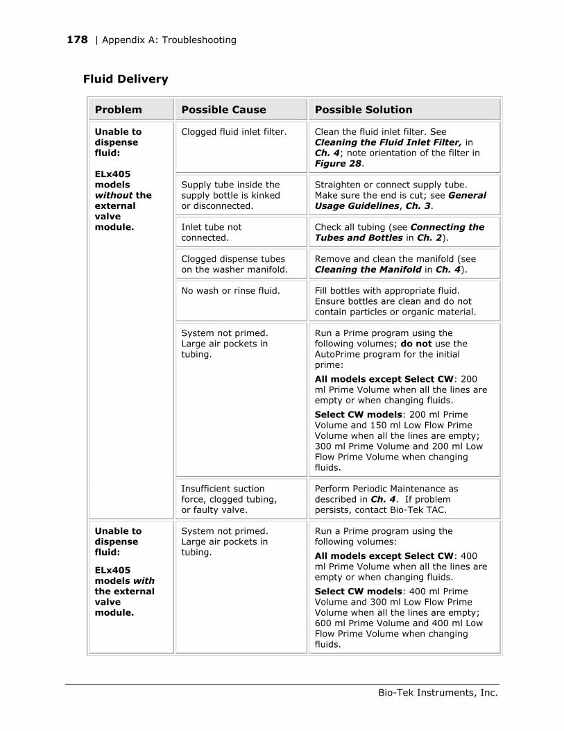
178 | Appendix A: Troubleshooting
Fluid Delivery
Problem Possible Cause Possible Solution
Clogged fluid inlet filter. Clean the fluid inlet filter. See Cleaning the Fluid Inlet Filter, in Ch. 4; note orientation of the filter in Figure 28.
Supply tube inside the supply bottle is kinked or disconnected.
Straighten or connect supply tube. Make sure the end is cut; see General Usage Guidelines, Ch. 3.
Inlet tube not connected.
Check all tubing (see Connecting the Tubes and Bottles in Ch. 2).
Clogged dispense tubes on the washer manifold.
Remove and clean the manifold (see Cleaning the Manifold in Ch. 4).
No wash or rinse fluid. Fill bottles with appropriate fluid. Ensure bottles are clean and do not contain particles or organic material.
System not primed. Large air pockets in tubing.
Run a Prime program using the following volumes; do not use the AutoPrime program for the initial prime:
All models except Select CW: 200 ml Prime Volume when all the lines are empty or when changing fluids.
Select CW models: 200 ml Prime Volume and 150 ml Low Flow Prime Volume when all the lines are empty; 300 ml Prime Volume and 200 ml Low Flow Prime Volume when changing fluids.
Unable to dispense fluid: ELx405 models without the external valve module.
Insufficient suction force, clogged tubing, or faulty valve.
Perform Periodic Maintenance as described in Ch. 4. If problem persists, contact Bio-Tek TAC.
Unable to dispense fluid:
ELx405 models with the external valve module.
System not primed. Large air pockets in tubing.
Run a Prime program using the following volumes:
All models except Select CW: 400 ml Prime Volume when all the lines are empty or when changing fluids.
Select CW models: 400 ml Prime Volume and 300 ml Low Flow Prime Volume when all the lines are empty; 600 ml Prime Volume and 400 ml Low Flow Prime Volume when changing fluids.
Bio-Tek Instruments, Inc.
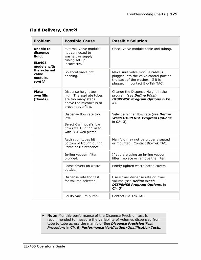
Troubleshooting Charts | 179
Fluid Delivery, Cont’d
Problem Possible Cause Possible Solution
External valve module not connected to washer, or supply tubing set up incorrectly.
Check valve module cable and tubing.
Unable to dispense fluid:
ELx405 models with the external valve module, cont’d.
Solenoid valve not opening.
Make sure valve module cable is plugged into the valve control port on the back of the washer. If it is plugged in, contact Bio-Tek TAC.
Dispense height too high. The aspirate tubes are too many steps above the microwells to prevent overflow.
Change the Dispense Height in the program (see Define Wash DISPENSE Program Options in Ch. 3).
Dispense flow rate too low.
Select CW model’s low flow rate 10 or 11 used with 384-well plates.
Select a higher flow rate (see Define Wash DISPENSE Program Options in Ch. 3).
Aspiration tubes hit bottom of trough during Prime or Maintenance.
Manifold may not be properly seated or mounted. Contact Bio-Tek TAC.
In-line vacuum filter plugged.
If you are using an in-line vacuum filter, replace or remove the filter.
Loose covers on waste bottles.
Firmly tighten waste bottle covers.
Dispense rate too fast for volume selected.
Use slower dispense rate or lower volume (see Define Wash DISPENSE Program Options, in Ch. 3).
Plate overfills (floods).
Faulty vacuum pump. Contact Bio-Tek TAC.
Note: Monthly performance of the Dispense Precision test is recommended to measure the variability of volumes dispensed from tube to tube across the manifold. See Dispense Precision Test Procedure in Ch. 5, Performance Verification/Qualification Tests.
ELx405 Operator's Guide
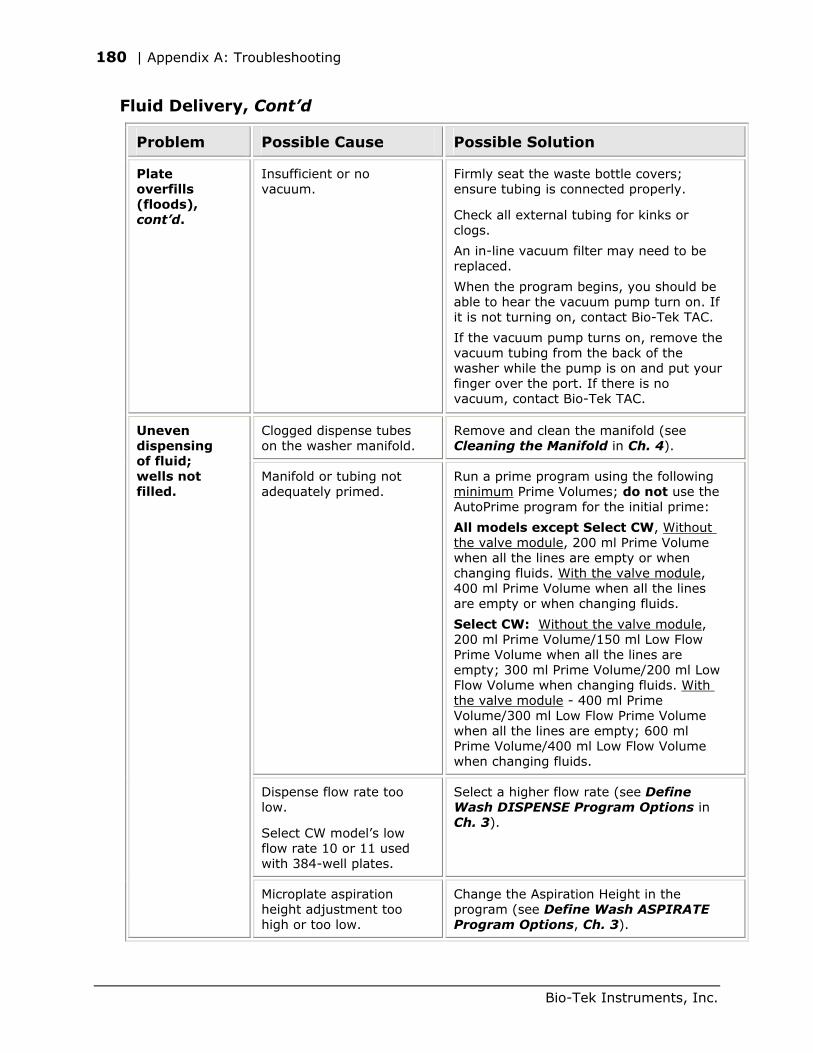
180 | Appendix A: Troubleshooting
Fluid Delivery, Cont’d
Problem Possible Cause Possible Solution
Plate overfills (floods), cont’d.
Insufficient or no vacuum.
Firmly seat the waste bottle covers; ensure tubing is connected properly.
Check all external tubing for kinks or clogs.
An in-line vacuum filter may need to be replaced.
When the program begins, you should be able to hear the vacuum pump turn on. If it is not turning on, contact Bio-Tek TAC.
If the vacuum pump turns on, remove the vacuum tubing from the back of the washer while the pump is on and put your finger over the port. If there is no vacuum, contact Bio-Tek TAC.
Clogged dispense tubes on the washer manifold.
Remove and clean the manifold (see Cleaning the Manifold in Ch. 4).
Manifold or tubing not adequately primed.
Run a prime program using the following minimum Prime Volumes; do not use the AutoPrime program for the initial prime:
All models except Select CW, Without the valve module, 200 ml Prime Volume when all the lines are empty or when changing fluids. With the valve module, 400 ml Prime Volume when all the lines are empty or when changing fluids.
Select CW: Without the valve module, 200 ml Prime Volume/150 ml Low Flow Prime Volume when all the lines are empty; 300 ml Prime Volume/200 ml Low Flow Volume when changing fluids. With the valve module - 400 ml Prime Volume/300 ml Low Flow Prime Volume when all the lines are empty; 600 ml Prime Volume/400 ml Low Flow Volume when changing fluids.
Dispense flow rate too low.
Select CW model’s low flow rate 10 or 11 used with 384-well plates.
Select a higher flow rate (see Define Wash DISPENSE Program Options in Ch. 3).
Uneven dispensing of fluid; wells not filled.
Microplate aspiration height adjustment too high or too low.
Change the Aspiration Height in the program (see Define Wash ASPIRATE Program Options, Ch. 3).
Bio-Tek Instruments, Inc.
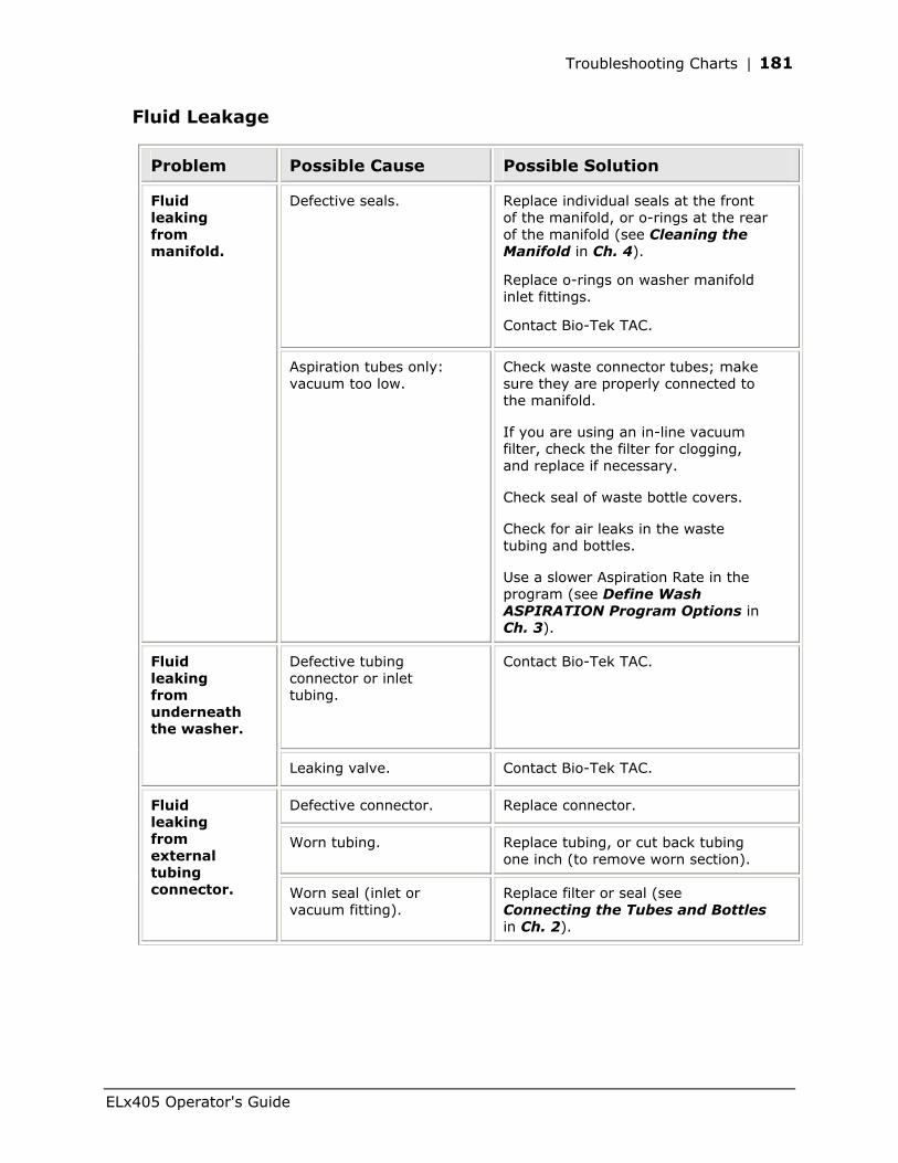
Troubleshooting Charts | 181
Fluid Leakage
Problem Possible Cause Possible Solution
Defective seals. Replace individual seals at the front of the manifold, or o-rings at the rear of the manifold (see Cleaning the Manifold in Ch. 4).
Replace o-rings on washer manifold inlet fittings.
Contact Bio-Tek TAC.
Fluid leaking from manifold.
Aspiration tubes only: vacuum too low.
Check waste connector tubes; make sure they are properly connected to the manifold.
If you are using an in-line vacuum filter, check the filter for clogging, and replace if necessary.
Check seal of waste bottle covers.
Check for air leaks in the waste tubing and bottles.
Use a slower Aspiration Rate in the program (see Define Wash ASPIRATION Program Options in Ch. 3).
Defective tubing connector or inlet tubing.
Contact Bio-Tek TAC. Fluid leaking from underneath the washer.
Leaking valve. Contact Bio-Tek TAC.
Defective connector. Replace connector.
Worn tubing. Replace tubing, or cut back tubing one inch (to remove worn section).
Fluid leaking from external tubing connector. Worn seal (inlet or
vacuum fitting). Replace filter or seal (see Connecting the Tubes and Bottles in Ch. 2).
ELx405 Operator's Guide
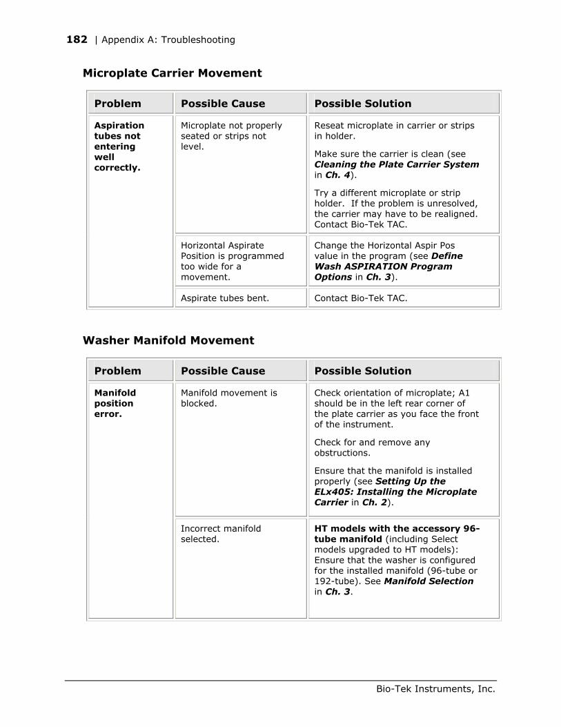
182 | Appendix A: Troubleshooting
Microplate Carrier Movement
Problem Possible Cause Possible Solution
Microplate not properly seated or strips not level.
Reseat microplate in carrier or strips in holder.
Make sure the carrier is clean (see Cleaning the Plate Carrier System in Ch. 4).
Try a different microplate or strip holder. If the problem is unresolved, the carrier may have to be realigned. Contact Bio-Tek TAC.
Horizontal Aspirate Position is programmed too wide for a movement.
Change the Horizontal Aspir Pos value in the program (see Define Wash ASPIRATION Program Options in Ch. 3).
Aspiration tubes not entering well correctly.
Aspirate tubes bent. Contact Bio-Tek TAC.
Washer Manifold Movement
Problem Possible Cause Possible Solution
Manifold movement is blocked.
Check orientation of microplate; A1 should be in the left rear corner of the plate carrier as you face the front of the instrument.
Check for and remove any obstructions.
Ensure that the manifold is installed properly (see Setting Up the ELx405: Installing the Microplate Carrier in Ch. 2).
Manifold position error.
Incorrect manifold selected.
HT models with the accessory 96-tube manifold (including Select models upgraded to HT models): Ensure that the washer is configured for the installed manifold (96-tube or 192-tube). See Manifold Selection in Ch. 3.
Bio-Tek Instruments, Inc.
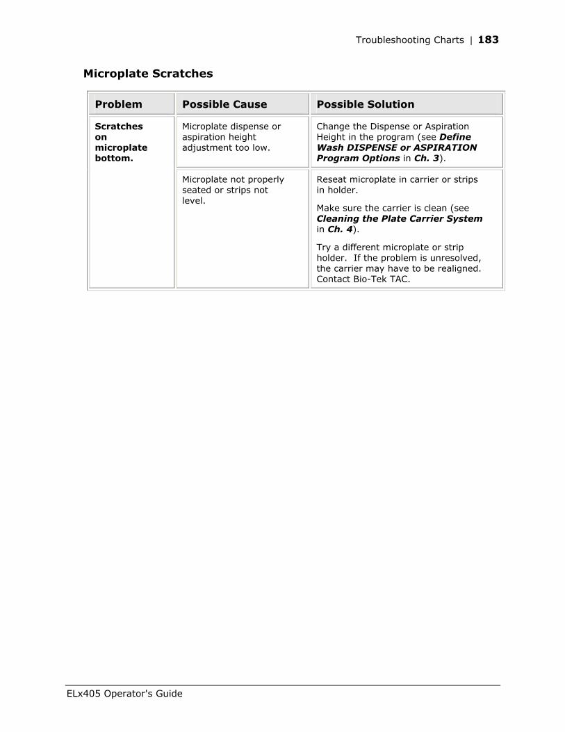
Troubleshooting Charts | 183
Microplate Scratches
Problem Possible Cause Possible Solution
Microplate dispense or aspiration height adjustment too low.
Change the Dispense or Aspiration Height in the program (see Define Wash DISPENSE or ASPIRATION Program Options in Ch. 3).
Scratches on microplate bottom.
Microplate not properly seated or strips not level.
Reseat microplate in carrier or strips in holder.
Make sure the carrier is clean (see Cleaning the Plate Carrier System in Ch. 4).
Try a different microplate or strip holder. If the problem is unresolved, the carrier may have to be realigned. Contact Bio-Tek TAC.
ELx405 Operator's Guide

184 | Appendix A: Troubleshooting
Bio-Tek Instruments, Inc.
Appendix B
Error Codes
This appendix lists error codes that may appear on the ELx405 Microplate Washer. If an error is displayed, refer to Appendix A, Troubleshooting. Contact Bio-Tek’s Technical Assistance Center if further instructions are necessary.
Error Codes ............................................................................186 General Errors.........................................................................187 Fatal Errors.............................................................................200 Bio-Stack Errors ......................................................................203
186 | Appendix B: Error Codes
Error Codes
An error code is displayed on the ELx405™ as a four-digit identifier. The first digit will be 0, 1, 2, 3, or A.
• 0, 1, 2, 3, or 4 denote a noncritical (General) error, which means that the instrument will still respond to keypad input. See General Errors, page 187.
• A denotes a more serious (Fatal) error, which requires that the ELx405 be turned off and then powered up. Upon restarting the washer, you should be able to enter commands into the keypad. See Fatal Errors, page 200.
If an error is displayed, refer to Appendix A, Troubleshooting. Contact Bio-Tek’s Technical Assistance Center if further instructions are necessary.
Bio-Stack Errors
Error codes displayed on the washer during operation with the Bio-Stack Microplate Stacker, that are prefixed with a B-, indicate either errors generated by the Bio-Stack or problems with communication between the two instruments.
Page 203 contains a partial listing of errors that may appear on the display of the ELx405 during operation with the Bio-Stack. Refer to the Troubleshooting and Error Codes section of your Bio-Stack Operator’s Manual for a more complete listing of these types of error codes and their descriptions.
Bio-Tek Instruments, Inc.
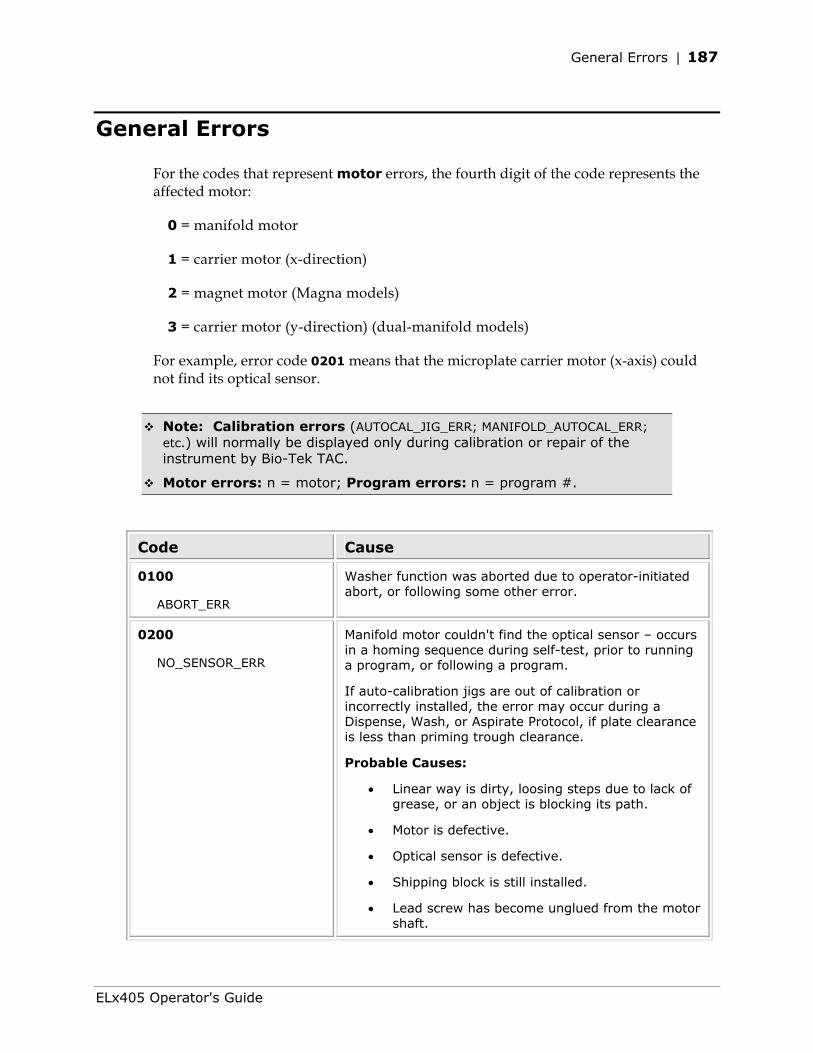
General Errors | 187
General Errors
For the codes that represent motor errors, the fourth digit of the code represents the affected motor:
0 = manifold motor
1 = carrier motor (x-direction)
2 = magnet motor (Magna models)
3 = carrier motor (y-direction) (dual-manifold models)
For example, error code 0201 means that the microplate carrier motor (x-axis) could not find its optical sensor.
Note: Calibration errors (AUTOCAL_JIG_ERR; MANIFOLD_AUTOCAL_ERR;
etc.) will normally be displayed only during calibration or repair of the instrument by Bio-Tek TAC.
Motor errors: n = motor; Program errors: n = program #.
Code Cause
0100
ABORT_ERR
Washer function was aborted due to operator-initiated abort, or following some other error.
0200
NO_SENSOR_ERR
Manifold motor couldn't find the optical sensor – occurs in a homing sequence during self-test, prior to running a program, or following a program.
If auto-calibration jigs are out of calibration or incorrectly installed, the error may occur during a Dispense, Wash, or Aspirate Protocol, if plate clearance is less than priming trough clearance.
Probable Causes:
• Linear way is dirty, loosing steps due to lack of grease, or an object is blocking its path.
• Motor is defective.
• Optical sensor is defective.
• Shipping block is still installed.
• Lead screw has become unglued from the motor shaft.
ELx405 Operator's Guide
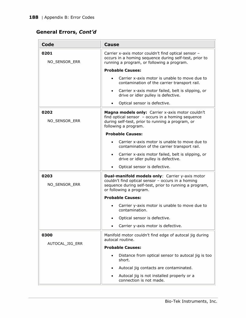
188 | Appendix B: Error Codes
General Errors, Cont’d
Code Cause
0201
NO_SENSOR_ERR
Carrier x-axis motor couldn’t find optical sensor – occurs in a homing sequence during self-test, prior to running a program, or following a program.
Probable Causes:
• Carrier x-axis motor is unable to move due to contamination of the carrier transport rail.
• Carrier x-axis motor failed, belt is slipping, or drive or idler pulley is defective.
• Optical sensor is defective.
0202
NO_SENSOR_ERR
Magna models only: Carrier x-axis motor couldn’t find optical sensor – occurs in a homing sequence during self-test, prior to running a program, or following a program.
Probable Causes:
• Carrier x-axis motor is unable to move due to contamination of the carrier transport rail.
• Carrier x-axis motor failed, belt is slipping, or drive or idler pulley is defective.
• Optical sensor is defective.
0203
NO_SENSOR_ERR
Dual-manifold models only: Carrier y-axis motor couldn’t find optical sensor – occurs in a homing sequence during self-test, prior to running a program, or following a program.
Probable Causes:
• Carrier y-axis motor is unable to move due to contamination.
• Optical sensor is defective.
• Carrier y-axis motor is defective.
0300
AUTOCAL_JIG_ERR
Manifold motor couldn’t find edge of autocal jig during autocal routine.
Probable Causes:
• Distance from optical sensor to autocal jig is too short.
• Autocal jig contacts are contaminated.
• Autocal jig is not installed properly or a connection is not made.
Bio-Tek Instruments, Inc.
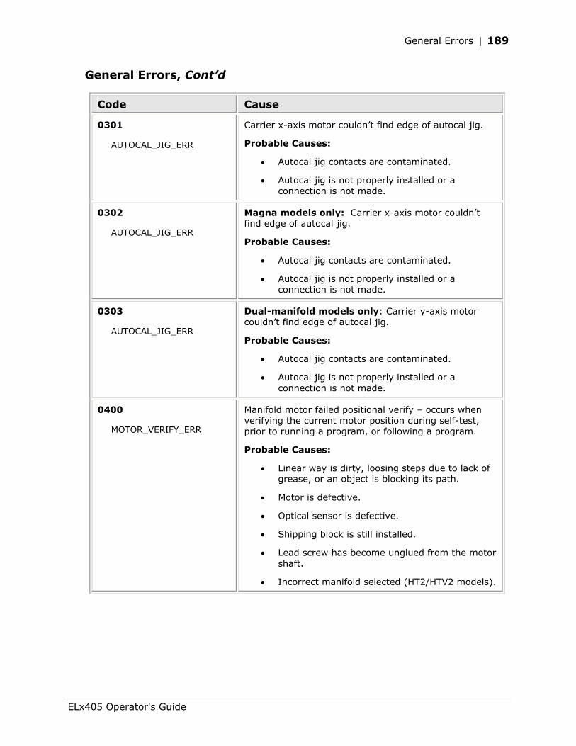
General Errors | 189
General Errors, Cont’d
Code Cause
0301
AUTOCAL_JIG_ERR
Carrier x-axis motor couldn’t find edge of autocal jig.
Probable Causes:
• Autocal jig contacts are contaminated.
• Autocal jig is not properly installed or a connection is not made.
0302
AUTOCAL_JIG_ERR
Magna models only: Carrier x-axis motor couldn’t find edge of autocal jig.
Probable Causes:
• Autocal jig contacts are contaminated.
• Autocal jig is not properly installed or a connection is not made.
0303
AUTOCAL_JIG_ERR
Dual-manifold models only: Carrier y-axis motor couldn’t find edge of autocal jig.
Probable Causes:
• Autocal jig contacts are contaminated.
• Autocal jig is not properly installed or a connection is not made.
0400
MOTOR_VERIFY_ERR
Manifold motor failed positional verify – occurs when verifying the current motor position during self-test, prior to running a program, or following a program.
Probable Causes:
• Linear way is dirty, loosing steps due to lack of grease, or an object is blocking its path.
• Motor is defective.
• Optical sensor is defective.
• Shipping block is still installed.
• Lead screw has become unglued from the motor shaft.
• Incorrect manifold selected (HT2/HTV2 models).
ELx405 Operator's Guide
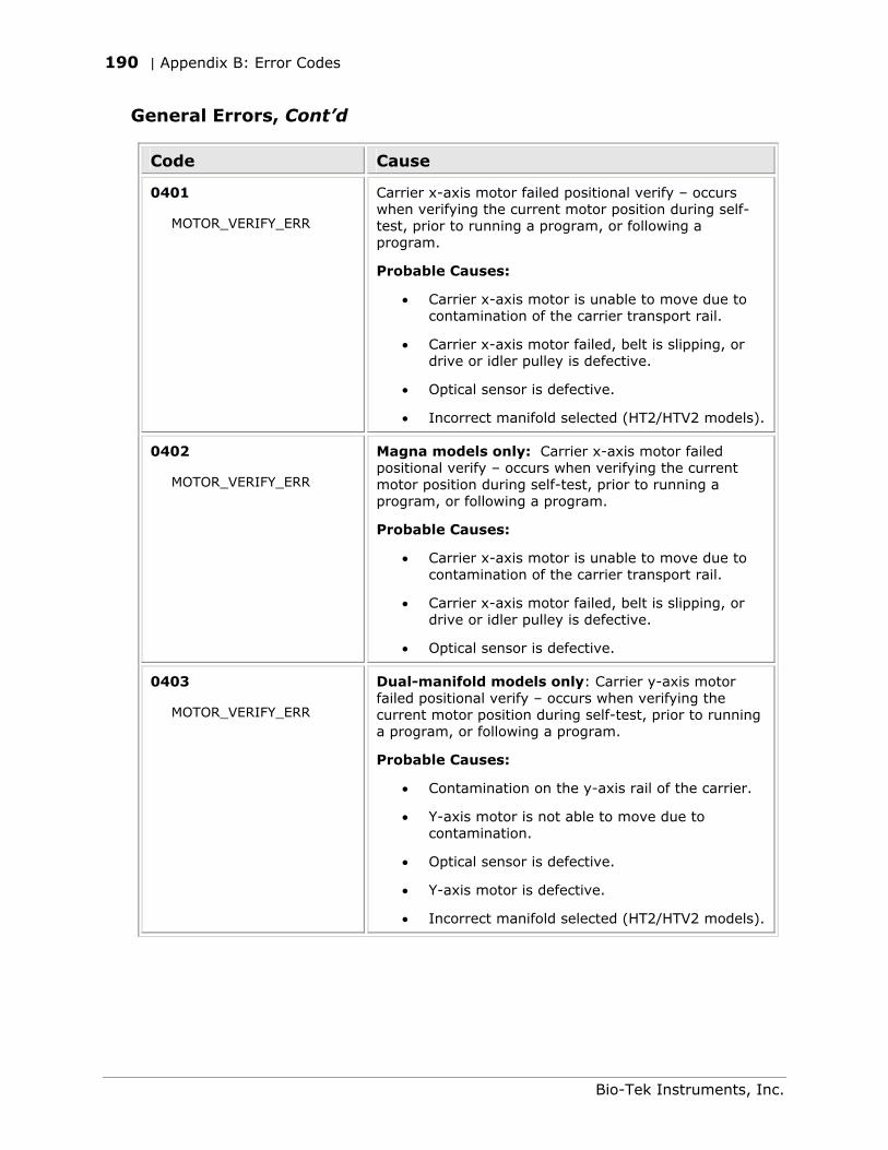
190 | Appendix B: Error Codes
General Errors, Cont’d
Code Cause
0401
MOTOR_VERIFY_ERR
Carrier x-axis motor failed positional verify – occurs when verifying the current motor position during self-test, prior to running a program, or following a program.
Probable Causes:
• Carrier x-axis motor is unable to move due to contamination of the carrier transport rail.
• Carrier x-axis motor failed, belt is slipping, or drive or idler pulley is defective.
• Optical sensor is defective.
• Incorrect manifold selected (HT2/HTV2 models).
0402
MOTOR_VERIFY_ERR
Magna models only: Carrier x-axis motor failed positional verify – occurs when verifying the current motor position during self-test, prior to running a program, or following a program.
Probable Causes:
• Carrier x-axis motor is unable to move due to contamination of the carrier transport rail.
• Carrier x-axis motor failed, belt is slipping, or drive or idler pulley is defective.
• Optical sensor is defective.
0403
MOTOR_VERIFY_ERR
Dual-manifold models only: Carrier y-axis motor failed positional verify – occurs when verifying the current motor position during self-test, prior to running a program, or following a program.
Probable Causes:
• Contamination on the y-axis rail of the carrier.
• Y-axis motor is not able to move due to contamination.
• Optical sensor is defective.
• Y-axis motor is defective.
• Incorrect manifold selected (HT2/HTV2 models).
Bio-Tek Instruments, Inc.
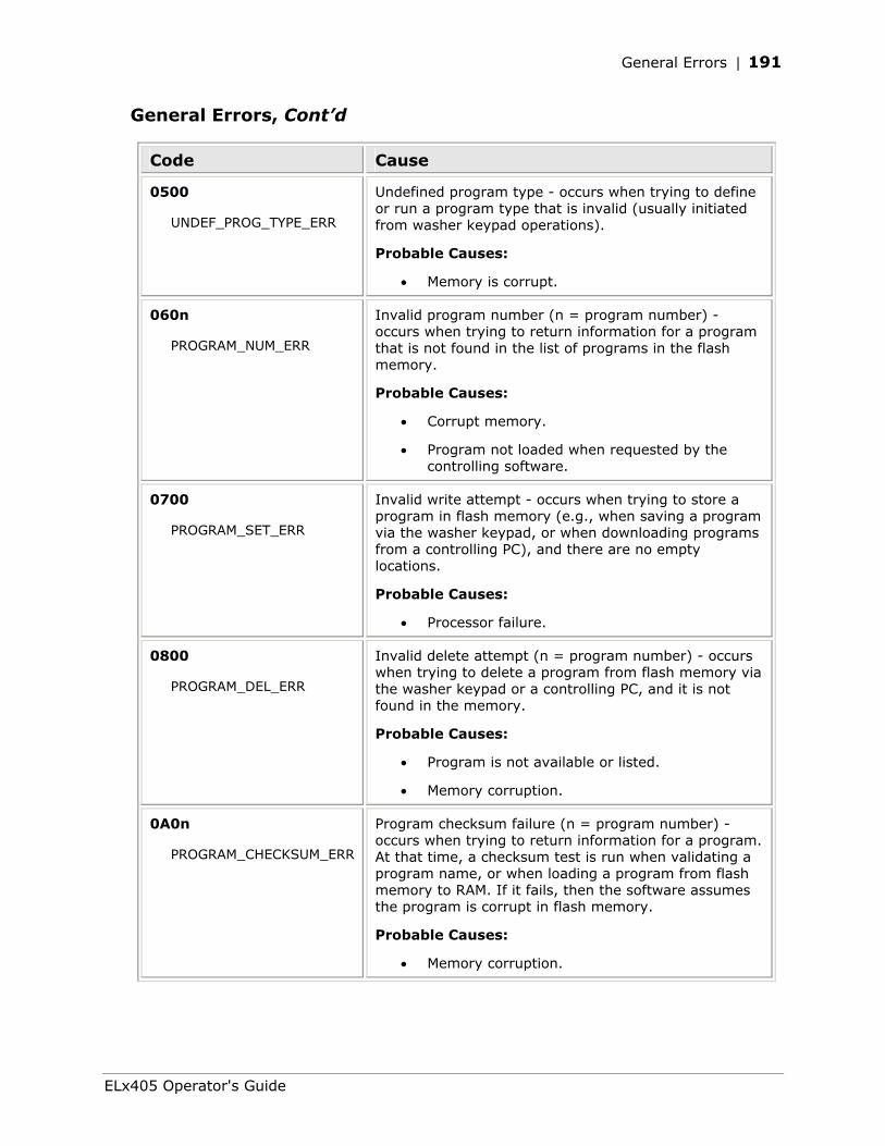
General Errors | 191
General Errors, Cont’d
Code Cause
0500
UNDEF_PROG_TYPE_ERR
Undefined program type - occurs when trying to define or run a program type that is invalid (usually initiated from washer keypad operations).
Probable Causes:
• Memory is corrupt.
060n
PROGRAM_NUM_ERR
Invalid program number (n = program number) - occurs when trying to return information for a program that is not found in the list of programs in the flash memory.
Probable Causes:
• Corrupt memory.
• Program not loaded when requested by the controlling software.
0700
PROGRAM_SET_ERR
Invalid write attempt - occurs when trying to store a program in flash memory (e.g., when saving a program via the washer keypad, or when downloading programs from a controlling PC), and there are no empty locations.
Probable Causes:
• Processor failure.
0800
PROGRAM_DEL_ERR
Invalid delete attempt (n = program number) - occurs when trying to delete a program from flash memory via the washer keypad or a controlling PC, and it is not found in the memory.
Probable Causes:
• Program is not available or listed.
• Memory corruption.
0A0n
PROGRAM_CHECKSUM_ERR
Program checksum failure (n = program number) - occurs when trying to return information for a program. At that time, a checksum test is run when validating a program name, or when loading a program from flash memory to RAM. If it fails, then the software assumes the program is corrupt in flash memory.
Probable Causes:
• Memory corruption.
ELx405 Operator's Guide
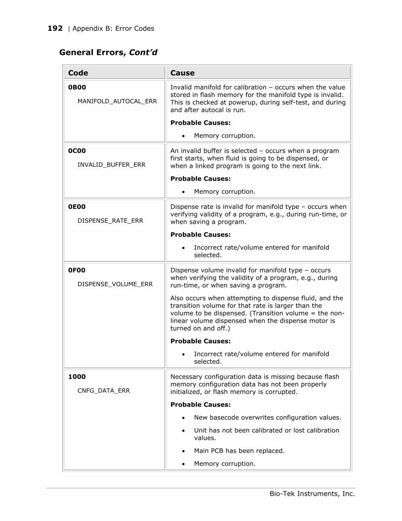
192 | Appendix B: Error Codes
General Errors, Cont’d
Code Cause
0B00
MANIFOLD_AUTOCAL_ERR
Invalid manifold for calibration – occurs when the value stored in flash memory for the manifold type is invalid. This is checked at powerup, during self-test, and during and after autocal is run.
Probable Causes:
• Memory corruption.
0C00
INVALID_BUFFER_ERR
An invalid buffer is selected – occurs when a program first starts, when fluid is going to be dispensed, or when a linked program is going to the next link.
Probable Causes:
• Memory corruption.
0E00
DISPENSE_RATE_ERR
Dispense rate is invalid for manifold type – occurs when verifying validity of a program, e.g., during run-time, or when saving a program.
Probable Causes:
• Incorrect rate/volume entered for manifold selected.
0F00
DISPENSE_VOLUME_ERR
Dispense volume invalid for manifold type – occurs when verifying the validity of a program, e.g., during run-time, or when saving a program.
Also occurs when attempting to dispense fluid, and the transition volume for that rate is larger than the volume to be dispensed. (Transition volume = the non-linear volume dispensed when the dispense motor is turned on and off.)
Probable Causes:
• Incorrect rate/volume entered for manifold selected.
1000
CNFG_DATA_ERR
Necessary configuration data is missing because flash memory configuration data has not been properly initialized, or flash memory is corrupted.
Probable Causes:
• New basecode overwrites configuration values.
• Unit has not been calibrated or lost calibration values.
• Main PCB has been replaced.
• Memory corruption.
Bio-Tek Instruments, Inc.
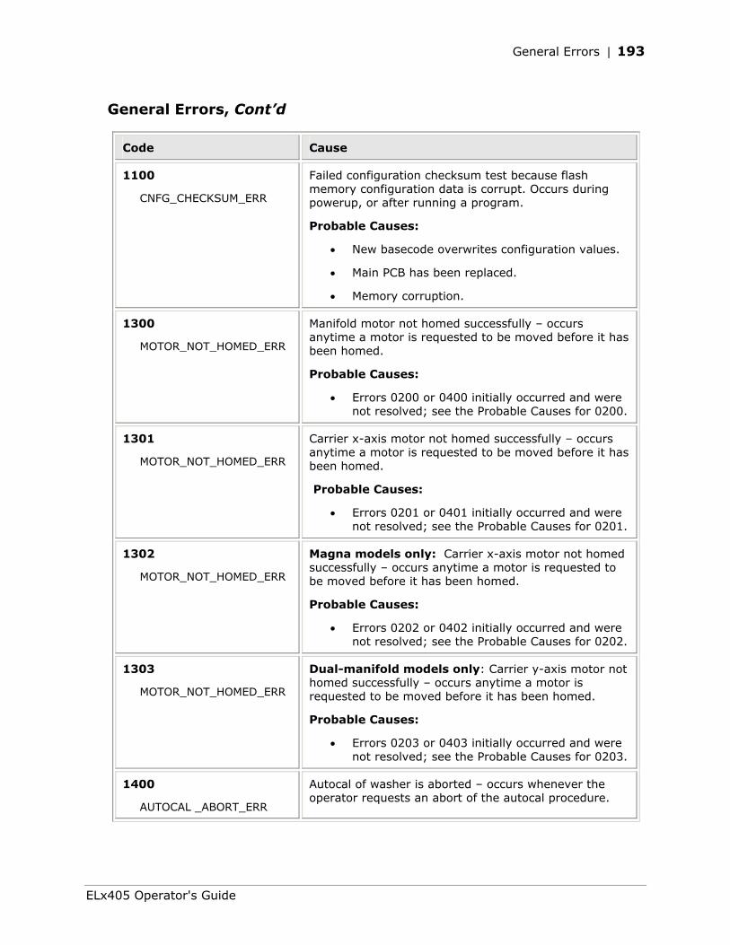
General Errors | 193
General Errors, Cont’d
Code Cause
1100
CNFG_CHECKSUM_ERR
Failed configuration checksum test because flash memory configuration data is corrupt. Occurs during powerup, or after running a program.
Probable Causes:
• New basecode overwrites configuration values.
• Main PCB has been replaced.
• Memory corruption.
1300
MOTOR_NOT_HOMED_ERR
Manifold motor not homed successfully – occurs anytime a motor is requested to be moved before it has been homed.
Probable Causes:
• Errors 0200 or 0400 initially occurred and were not resolved; see the Probable Causes for 0200.
1301
MOTOR_NOT_HOMED_ERR
Carrier x-axis motor not homed successfully – occurs anytime a motor is requested to be moved before it has been homed.
Probable Causes:
• Errors 0201 or 0401 initially occurred and were not resolved; see the Probable Causes for 0201.
1302
MOTOR_NOT_HOMED_ERR
Magna models only: Carrier x-axis motor not homed successfully – occurs anytime a motor is requested to be moved before it has been homed.
Probable Causes:
• Errors 0202 or 0402 initially occurred and were not resolved; see the Probable Causes for 0202.
1303
MOTOR_NOT_HOMED_ERR
Dual-manifold models only: Carrier y-axis motor not homed successfully – occurs anytime a motor is requested to be moved before it has been homed.
Probable Causes:
• Errors 0203 or 0403 initially occurred and were not resolved; see the Probable Causes for 0203.
1400
AUTOCAL _ABORT_ERR
Autocal of washer is aborted – occurs whenever the operator requests an abort of the autocal procedure.
ELx405 Operator's Guide
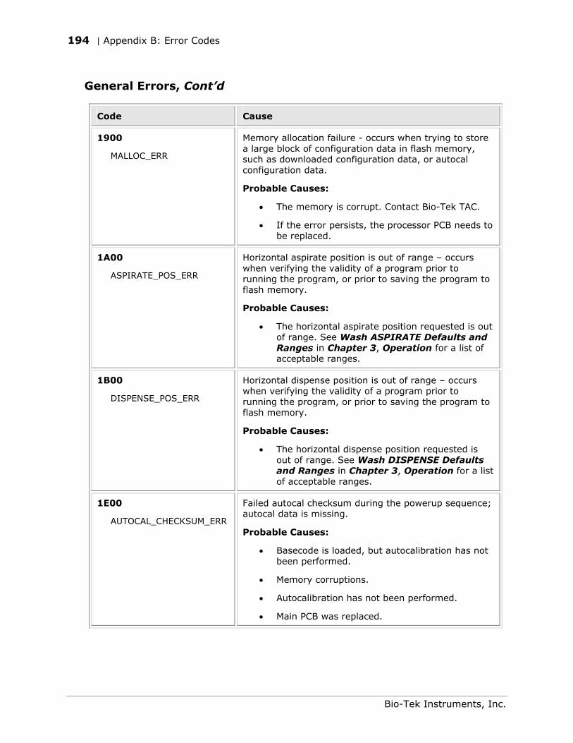
194 | Appendix B: Error Codes
General Errors, Cont’d
Code Cause
1900
MALLOC_ERR
Memory allocation failure - occurs when trying to store a large block of configuration data in flash memory, such as downloaded configuration data, or autocal configuration data.
Probable Causes:
• The memory is corrupt. Contact Bio-Tek TAC.
• If the error persists, the processor PCB needs to be replaced.
1A00
ASPIRATE_POS_ERR
Horizontal aspirate position is out of range – occurs when verifying the validity of a program prior to running the program, or prior to saving the program to flash memory.
Probable Causes:
• The horizontal aspirate position requested is out of range. See Wash ASPIRATE Defaults and Ranges in Chapter 3, Operation for a list of acceptable ranges.
1B00
DISPENSE_POS_ERR
Horizontal dispense position is out of range – occurs when verifying the validity of a program prior to running the program, or prior to saving the program to flash memory.
Probable Causes:
• The horizontal dispense position requested is out of range. See Wash DISPENSE Defaults and Ranges in Chapter 3, Operation for a list of acceptable ranges.
1E00
AUTOCAL_CHECKSUM_ERR
Failed autocal checksum during the powerup sequence; autocal data is missing.
Probable Causes:
• Basecode is loaded, but autocalibration has not been performed.
• Memory corruptions.
• Autocalibration has not been performed.
• Main PCB was replaced.
Bio-Tek Instruments, Inc.
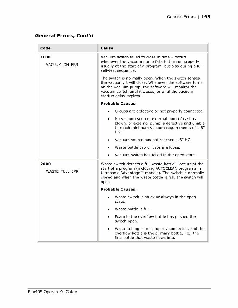
General Errors | 195
General Errors, Cont’d
Code Cause
1F00
VACUUM_ON_ERR
Vacuum switch failed to close in time – occurs whenever the vacuum pump fails to turn on properly, usually at the start of a program, but also during a full self-test sequence.
The switch is normally open. When the switch senses the vacuum, it will close. Whenever the software turns on the vacuum pump, the software will monitor the vacuum switch until it closes, or until the vacuum startup delay expires.
Probable Causes:
• Q-cups are defective or not properly connected.
• No vacuum source, external pump fuse has blown, or external pump is defective and unable to reach minimum vacuum requirements of 1.6” HG.
• Vacuum source has not reached 1.6” HG.
• Waste bottle cap or caps are loose.
• Vacuum switch has failed in the open state.
2000
WASTE_FULL_ERR
Waste switch detects a full waste bottle – occurs at the start of a program (including AUTOCLEAN programs in Ultrasonic Advantage™ models). The switch is normally closed and when the waste bottle is full, the switch will open.
Probable Causes:
• Waste switch is stuck or always in the open state.
• Waste bottle is full.
• Foam in the overflow bottle has pushed the switch open.
• Waste tubing is not properly connected, and the overflow bottle is the primary bottle, i.e., the first bottle that waste flows into.
ELx405 Operator's Guide
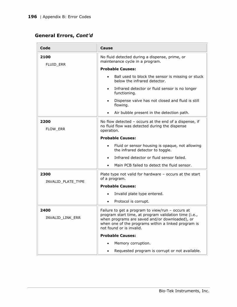
196 | Appendix B: Error Codes
General Errors, Cont’d
Code Cause
2100
FLUID_ERR
No fluid detected during a dispense, prime, or maintenance cycle in a program.
Probable Causes:
• Ball used to block the sensor is missing or stuck below the infrared detector.
• Infrared detector or fluid sensor is no longer functioning.
• Dispense valve has not closed and fluid is still flowing.
• Air bubble present in the detection path.
2200
FLOW_ERR
No flow detected – occurs at the end of a dispense, if no fluid flow was detected during the dispense operation.
Probable Causes:
• Fluid or sensor housing is opaque, not allowing the infrared detector to toggle.
• Infrared detector or fluid sensor failed.
• Main PCB failed to detect the fluid sensor.
2300
INVALID_PLATE_TYPE
Plate type not valid for hardware – occurs at the start of a program.
Probable Causes:
• Invalid plate type entered.
• Protocol is corrupt.
2400
INVALID_LINK_ERR
Failure to get a program to view/run – occurs at program start time, at program validation time (i.e., when programs are saved and/or downloaded), or when one of the programs within a linked program is not found or is invalid.
Probable Causes:
• Memory corruption.
• Requested program is corrupt or not available.
Bio-Tek Instruments, Inc.
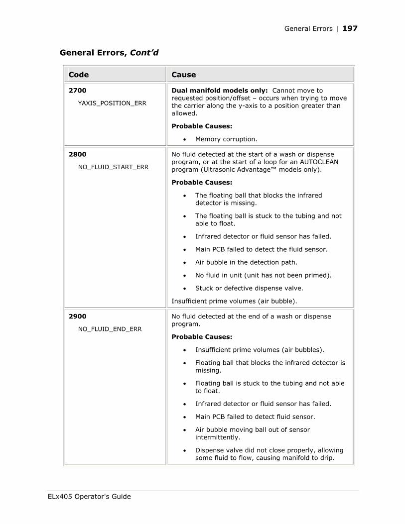
General Errors | 197
General Errors, Cont’d
Code Cause
2700
YAXIS_POSITION_ERR
Dual manifold models only: Cannot move to requested position/offset – occurs when trying to move the carrier along the y-axis to a position greater than allowed.
Probable Causes:
• Memory corruption.
2800
NO_FLUID_START_ERR
No fluid detected at the start of a wash or dispense program, or at the start of a loop for an AUTOCLEAN program (Ultrasonic Advantage™ models only).
Probable Causes:
• The floating ball that blocks the infrared detector is missing.
• The floating ball is stuck to the tubing and not able to float.
• Infrared detector or fluid sensor has failed.
• Main PCB failed to detect the fluid sensor.
• Air bubble in the detection path.
• No fluid in unit (unit has not been primed).
• Stuck or defective dispense valve.
Insufficient prime volumes (air bubble).
2900
NO_FLUID_END_ERR
No fluid detected at the end of a wash or dispense program.
Probable Causes:
• Insufficient prime volumes (air bubbles).
• Floating ball that blocks the infrared detector is missing.
• Floating ball is stuck to the tubing and not able to float.
• Infrared detector or fluid sensor has failed.
• Main PCB failed to detect fluid sensor.
• Air bubble moving ball out of sensor intermittently.
• Dispense valve did not close properly, allowing some fluid to flow, causing manifold to drip.
ELx405 Operator's Guide
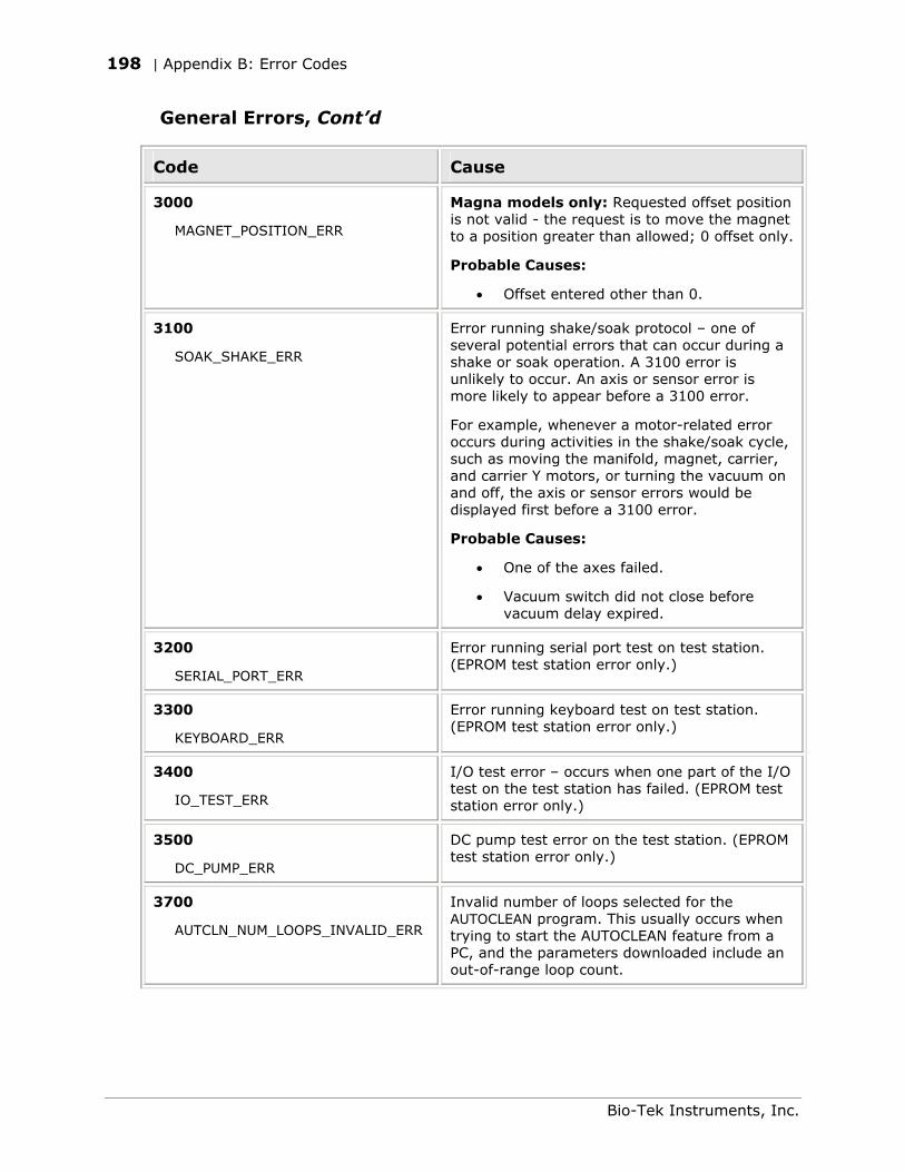
198 | Appendix B: Error Codes
General Errors, Cont’d
Code Cause
3000
MAGNET_POSITION_ERR
Magna models only: Requested offset position is not valid - the request is to move the magnet to a position greater than allowed; 0 offset only.
Probable Causes:
• Offset entered other than 0.
3100
SOAK_SHAKE_ERR
Error running shake/soak protocol – one of several potential errors that can occur during a shake or soak operation. A 3100 error is unlikely to occur. An axis or sensor error is more likely to appear before a 3100 error.
For example, whenever a motor-related error occurs during activities in the shake/soak cycle, such as moving the manifold, magnet, carrier, and carrier Y motors, or turning the vacuum on and off, the axis or sensor errors would be displayed first before a 3100 error.
Probable Causes:
• One of the axes failed.
• Vacuum switch did not close before vacuum delay expired.
3200
SERIAL_PORT_ERR
Error running serial port test on test station. (EPROM test station error only.)
3300
KEYBOARD_ERR
Error running keyboard test on test station. (EPROM test station error only.)
3400
IO_TEST_ERR
I/O test error – occurs when one part of the I/O test on the test station has failed. (EPROM test station error only.)
3500
DC_PUMP_ERR
DC pump test error on the test station. (EPROM test station error only.)
3700
AUTCLN_NUM_LOOPS_INVALID_ERR
Invalid number of loops selected for the AUTOCLEAN program. This usually occurs when trying to start the AUTOCLEAN feature from a PC, and the parameters downloaded include an out-of-range loop count.
Bio-Tek Instruments, Inc.
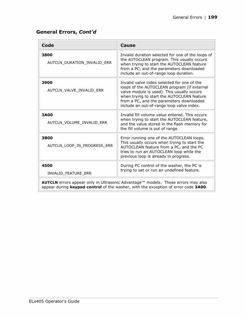
General Errors | 199
General Errors, Cont’d
Code Cause
3800
AUTCLN_DURATION_INVALID_ERR
Invalid duration selected for one of the loops of the AUTOCLEAN program. This usually occurs when trying to start the AUTOCLEAN feature from a PC, and the parameters downloaded include an out-of-range loop duration.
3900
AUTCLN_VALVE_INVALID_ERR
Invalid valve index selected for one of the loops of the AUTOCLEAN program (if external valve module is used). This usually occurs when trying to start the AUTOCLEAN feature from a PC, and the parameters downloaded include an out-of-range loop valve index.
3A00
AUTCLN_VOLUME_INVALID_ERR
Invalid fill volume value entered. This occurs when trying to start the AUTOCLEAN feature, and the value stored in the flash memory for the fill volume is out of range.
3B00
AUTCLN_LOOP_IN_PROGRESS_ERR
Error running one of the AUTOCLEAN loops. This usually occurs when trying to start the AUTOCLEAN feature from a PC, and the PC tries to run an AUTOCLEAN loop while the previous loop is already in progress.
4500
INVALID_FEATURE_ERR
During PC control of the washer, the PC is trying to set or run an undefined feature.
AUTCLN errors appear only in Ultrasonic Advantage™ models. These errors may also appear during keypad control of the washer, with the exception of error code 3A00.
ELx405 Operator's Guide
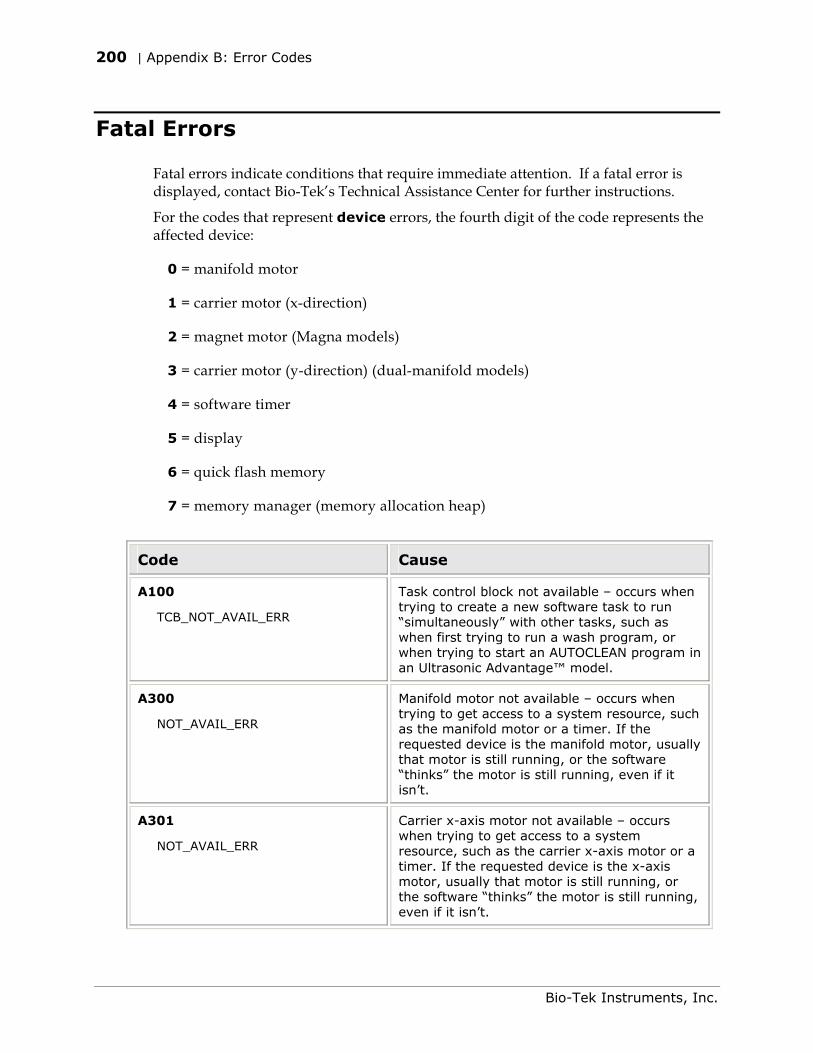
200 | Appendix B: Error Codes
Fatal Errors
Fatal errors indicate conditions that require immediate attention. If a fatal error is displayed, contact Bio-Tek’s Technical Assistance Center for further instructions.
For the codes that represent device errors, the fourth digit of the code represents the affected device:
0 = manifold motor
1 = carrier motor (x-direction)
2 = magnet motor (Magna models)
3 = carrier motor (y-direction) (dual-manifold models)
4 = software timer
5 = display
6 = quick flash memory
7 = memory manager (memory allocation heap)
Code Cause
A100
TCB_NOT_AVAIL_ERR
Task control block not available – occurs when trying to create a new software task to run “simultaneously” with other tasks, such as when first trying to run a wash program, or when trying to start an AUTOCLEAN program in an Ultrasonic Advantage™ model.
A300
NOT_AVAIL_ERR
Manifold motor not available – occurs when trying to get access to a system resource, such as the manifold motor or a timer. If the requested device is the manifold motor, usually that motor is still running, or the software “thinks” the motor is still running, even if it isn’t.
A301
NOT_AVAIL_ERR
Carrier x-axis motor not available – occurs when trying to get access to a system resource, such as the carrier x-axis motor or a timer. If the requested device is the x-axis motor, usually that motor is still running, or the software “thinks” the motor is still running, even if it isn’t.
Bio-Tek Instruments, Inc.
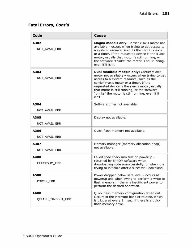
Fatal Errors | 201
Fatal Errors, Cont’d
Code Cause
A302
NOT_AVAIL_ERR
Magna models only: Carrier x-axis motor not available – occurs when trying to get access to a system resource, such as the carrier x-axis or a timer. If the requested device is the x-axis motor, usually that motor is still running, or the software “thinks” the motor is still running, even if it isn’t.
A303
NOT_AVAIL_ERR
Dual manifold models only: Carrier y-axis motor not available – occurs when trying to get access to a system resource, such as the carrier y-axis motor or a timer. If the requested device is the y-axis motor, usually that motor is still running, or the software “thinks” the motor is still running, even if it isn’t.
A304
NOT_AVAIL_ERR
Software timer not available.
A305
NOT_AVAIL_ERR
Display not available.
A306
NOT_AVAIL_ERR
Quick flash memory not available.
A307
NOT_AVAIL_ERR
Memory manager (memory allocation heap) not available.
A400
CHECKSUM_ERR
Failed code checksum test on powerup – returned by EPROM software when downloading code unsuccessfully, or when it is trying to initialize after a successful download.
A500
POWER_ERR
Power dropped below safe level – occurs at powerup and when trying to perform a write to flash memory, if there is insufficient power to perform the desired operation.
A600
QFLASH_TIMEOUT_ERR
Quick flash memory configuration timed out. Occurs in the interrupt handler routine, which is triggered every 1 msec, if there is a quick flash memory error.
ELx405 Operator's Guide
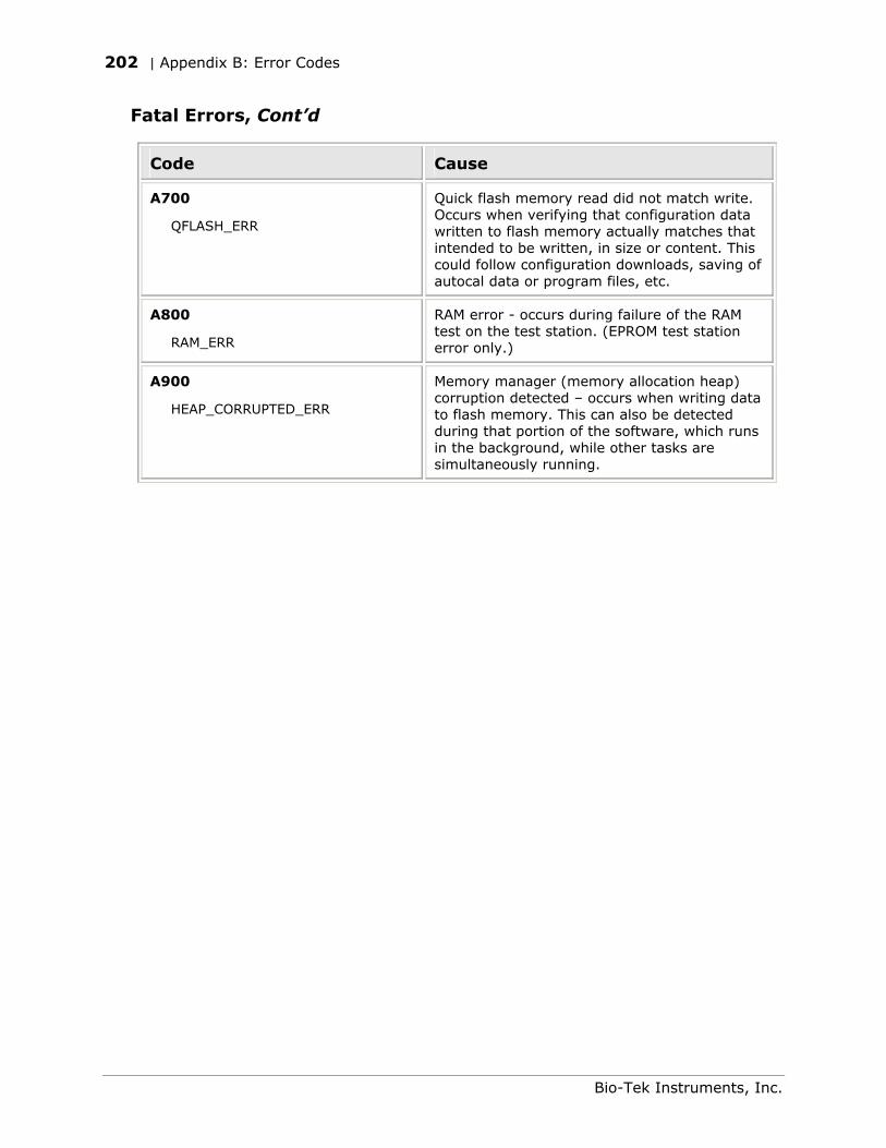
202 | Appendix B: Error Codes
Fatal Errors, Cont’d
Code Cause
A700
QFLASH_ERR
Quick flash memory read did not match write. Occurs when verifying that configuration data written to flash memory actually matches that intended to be written, in size or content. This could follow configuration downloads, saving of autocal data or program files, etc.
A800
RAM_ERR
RAM error - occurs during failure of the RAM test on the test station. (EPROM test station error only.)
A900
HEAP_CORRUPTED_ERR
Memory manager (memory allocation heap) corruption detected – occurs when writing data to flash memory. This can also be detected during that portion of the software, which runs in the background, while other tasks are simultaneously running.
Bio-Tek Instruments, Inc.
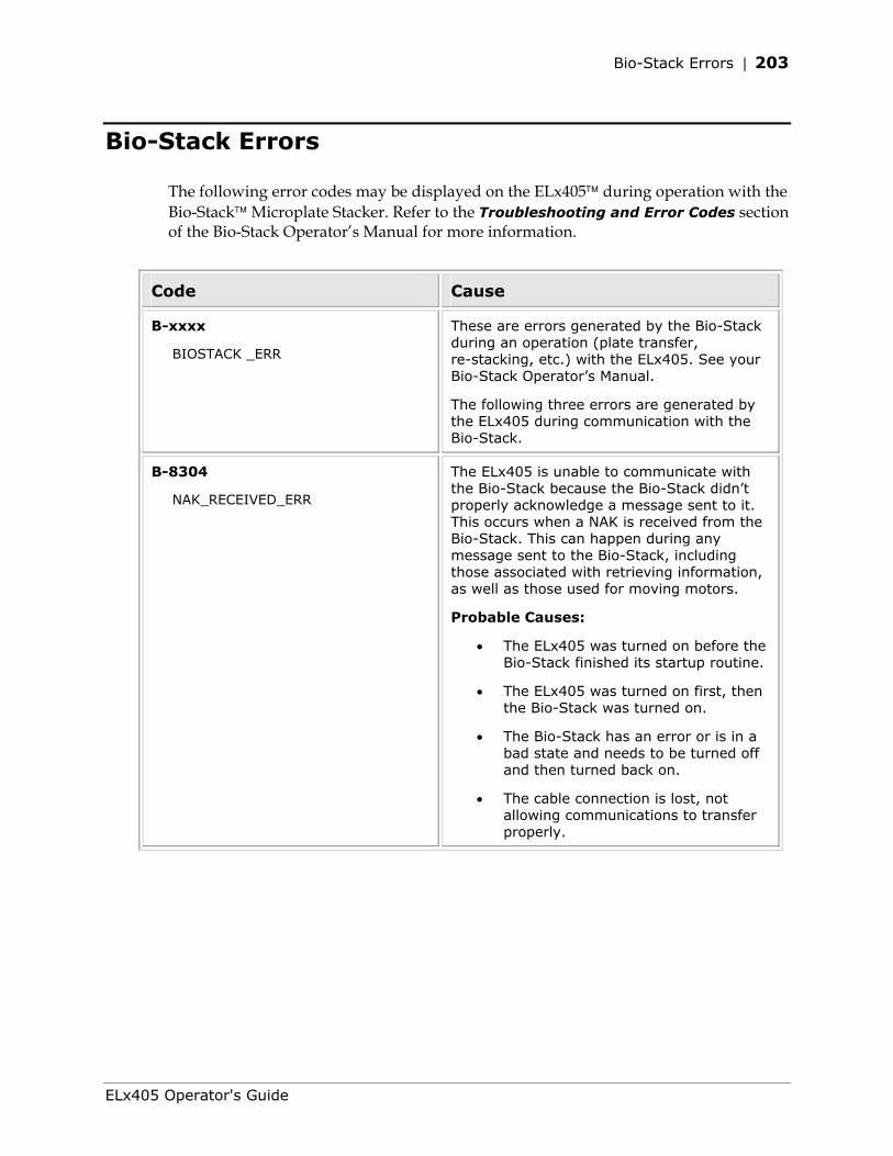
Bio-Stack Errors | 203
Bio-Stack Errors
The following error codes may be displayed on the ELx405 during operation with the Bio-Stack Microplate Stacker. Refer to the Troubleshooting and Error Codes section of the Bio-Stack Operator’s Manual for more information.
Code Cause
B-xxxx
BIOSTACK _ERR
These are errors generated by the Bio-Stack during an operation (plate transfer, re-stacking, etc.) with the ELx405. See your Bio-Stack Operator’s Manual.
The following three errors are generated by the ELx405 during communication with the Bio-Stack.
B-8304
NAK_RECEIVED_ERR
The ELx405 is unable to communicate with the Bio-Stack because the Bio-Stack didn’t properly acknowledge a message sent to it. This occurs when a NAK is received from the Bio-Stack. This can happen during any message sent to the Bio-Stack, including those associated with retrieving information, as well as those used for moving motors.
Probable Causes:
• The ELx405 was turned on before the Bio-Stack finished its startup routine.
• The ELx405 was turned on first, then the Bio-Stack was turned on.
• The Bio-Stack has an error or is in a bad state and needs to be turned off and then turned back on.
• The cable connection is lost, not allowing communications to transfer properly.
ELx405 Operator's Guide
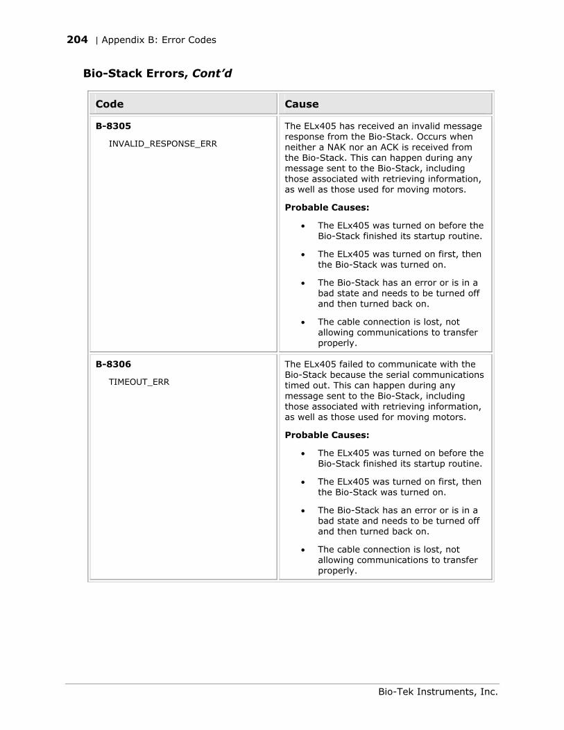
204 | Appendix B: Error Codes
Bio-Stack Errors, Cont’d
Code Cause
B-8305
INVALID_RESPONSE_ERR
The ELx405 has received an invalid message response from the Bio-Stack. Occurs when neither a NAK nor an ACK is received from the Bio-Stack. This can happen during any message sent to the Bio-Stack, including those associated with retrieving information, as well as those used for moving motors.
Probable Causes:
• The ELx405 was turned on before the Bio-Stack finished its startup routine.
• The ELx405 was turned on first, then the Bio-Stack was turned on.
• The Bio-Stack has an error or is in a bad state and needs to be turned off and then turned back on.
• The cable connection is lost, not allowing communications to transfer properly.
B-8306
TIMEOUT_ERR
The ELx405 failed to communicate with the Bio-Stack because the serial communications timed out. This can happen during any message sent to the Bio-Stack, including those associated with retrieving information, as well as those used for moving motors.
Probable Causes:
• The ELx405 was turned on before the Bio-Stack finished its startup routine.
• The ELx405 was turned on first, then the Bio-Stack was turned on.
• The Bio-Stack has an error or is in a bad state and needs to be turned off and then turned back on.
• The cable connection is lost, not allowing communications to transfer properly.
Bio-Tek Instruments, Inc.

Appendix C
Chemical Compatibility
This appendix lists the name and material(s) of each washer component that will come into contact with chemicals during operation or maintenance. If there are questions about compatibility of chemicals with the washer, contact Bio-Tek.
Components and Materials Composition ......................................206
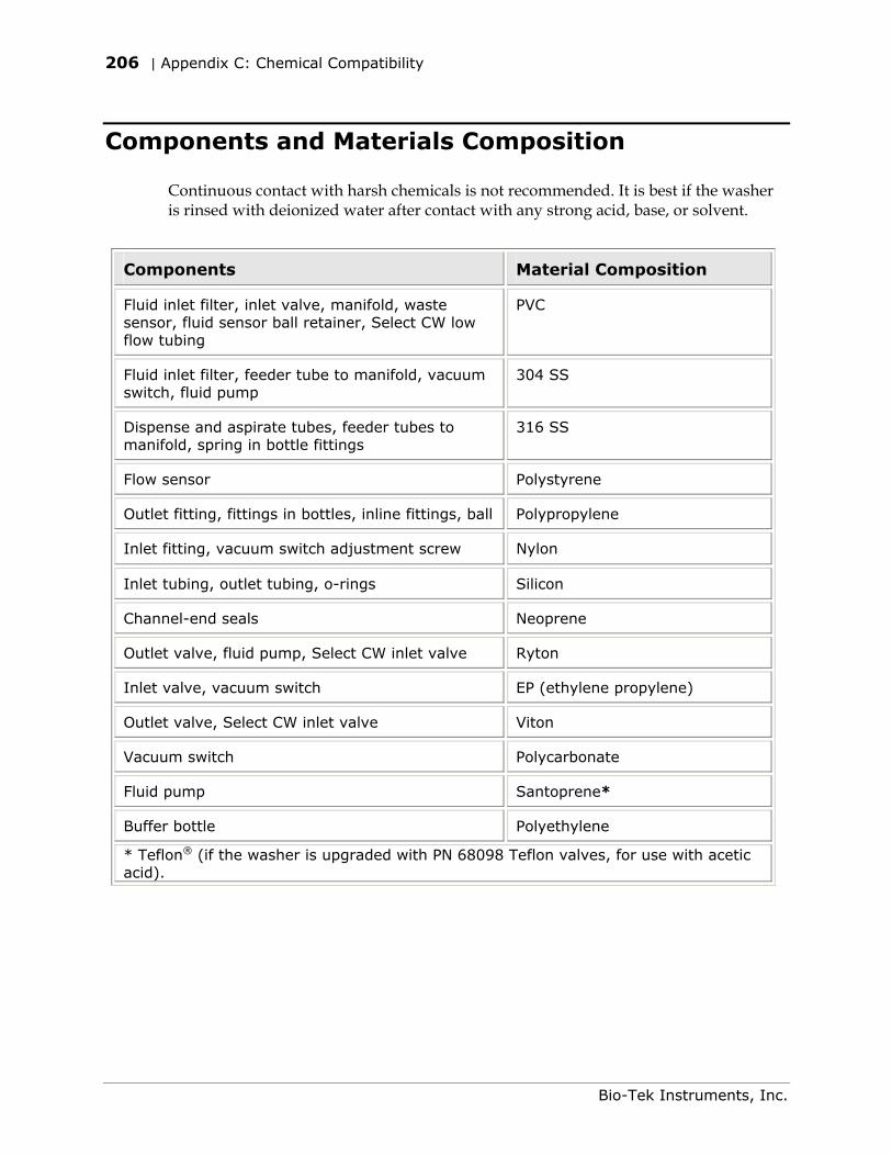
206 | Appendix C: Chemical Compatibility
Components and Materials Composition
Continuous contact with harsh chemicals is not recommended. It is best if the washer is rinsed with deionized water after contact with any strong acid, base, or solvent.
Components Material Composition
Fluid inlet filter, inlet valve, manifold, waste sensor, fluid sensor ball retainer, Select CW low flow tubing
PVC
Fluid inlet filter, feeder tube to manifold, vacuum switch, fluid pump
304 SS
Dispense and aspirate tubes, feeder tubes to manifold, spring in bottle fittings
316 SS
Flow sensor Polystyrene
Outlet fitting, fittings in bottles, inline fittings, ball Polypropylene
Inlet fitting, vacuum switch adjustment screw Nylon
Inlet tubing, outlet tubing, o-rings Silicon
Channel-end seals Neoprene
Outlet valve, fluid pump, Select CW inlet valve Ryton
Inlet valve, vacuum switch EP (ethylene propylene)
Outlet valve, Select CW inlet valve Viton
Vacuum switch Polycarbonate
Fluid pump Santoprene*
Buffer bottle Polyethylene
* Teflon® (if the washer is upgraded with PN 68098 Teflon valves, for use with acetic acid).
Bio-Tek Instruments, Inc.
Appendix D
Default Programs
This appendix lists all default wash, prime, dispense, aspirate, and maintenance programs available on the washer.
Default Programs.....................................................................208
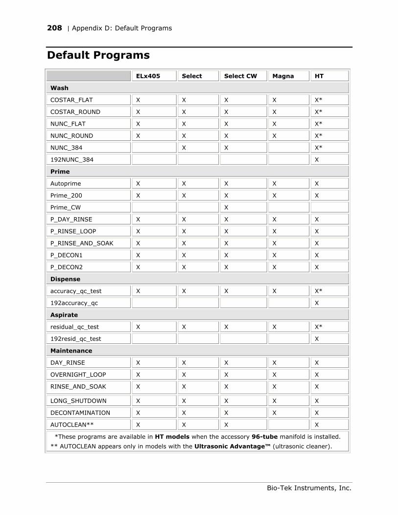
208 | Appendix D: Default Programs
Default Programs
ELx405 Select Select CW Magna HT
Wash
COSTAR_FLAT X X X X X*
COSTAR_ROUND X X X X X*
NUNC_FLAT X X X X X*
NUNC_ROUND X X X X X*
NUNC_384 X X X*
192NUNC_384 X
Prime
Autoprime X X X X X
Prime_200 X X X X X
Prime_CW X
P_DAY_RINSE X X X X X
P_RINSE_LOOP X X X X X
P_RINSE_AND_SOAK X X X X X
P_DECON1 X X X X X
P_DECON2 X X X X X
Dispense
accuracy_qc_test X X X X X*
192accuracy_qc X
Aspirate
residual_qc_test X X X X X*
192resid_qc_test X
Maintenance
DAY_RINSE X X X X X
OVERNIGHT_LOOP X X X X X
RINSE_AND_SOAK X X X X X
LONG_SHUTDOWN X X X X X
DECONTAMINATION X X X X X
AUTOCLEAN** X X X X
*These programs are available in HT models when the accessory 96-tube manifold is installed.
** AUTOCLEAN appears only in models with the Ultrasonic Advantage™ (ultrasonic cleaner).
Bio-Tek Instruments, Inc.

Appendix E
Changing the Manifolds
This appendix contains instructions for changing manifolds in ELx405 HT models with the accessory 96-tube manifold.
Changing Manifolds in HT Models With the 96-Tube Manifold............... 210
210 | Appendix E: Changing the Manifolds
Changing Manifolds in HT Models With the 96-Tube Manifold
HT models (HT2 and HTV2) that include the accessory 96-tube dual manifold are shipped with the 192-tube manifold installed, and the 96-tube manifold packaged in a special case (PN 7102136). This shipping case can be used to store whichever manifold is not being used (see Figure 30 on page 212).
Before removing the installed manifold, it is recommended that you first run a Maintenance program (such as DAY_RINSE) to flush remaining residue from the manifold tubes, if the washer has been in operation.
Tip: It will be easier to clean the manifold now, before removing and storing it, rather than after residuals in the manifold tubing and fluid paths have been allowed to dry or crystallize during storage.
1. Run DAY_RINSE, using deionized water in the supply bottle.
2. Run the system “dry”:
From the main menu, select UTIL SETUP SENSOR and set VACUUM DETECTION, FLUID DETECTION, AND FLOW DETECTION to NO.
Connect an empty supply bottle and run DAY_RINSE.
Important! Set the vacuum, fluid, and flow detection sensors back to YES.
HT models with the Ultrasonic Advantage™ (ultrasonic cleaner): Run an AUTOCLEAN program instead of DAY_RINSE.
3. Turn off the washer and disconnect the power cord.
4. Remove the mist shield (if it is attached): using your fingers, loosen the two thumbscrews that fasten the shield to the front base of the washer, and set them aside, with the shield.
5. Using the 9/64” (3.57 mm) hex wrench supplied with the instrument, remove the screws, washers, and springs that hold the manifold in place, and set them aside.
6. Carefully remove the manifold and end plates, holding the upper and lower manifolds together as a single unit, and place the manifold into the shipping case for safe storage. If you ran DAY_RINSE or an AUTOCLEAN program as instructed in step 1 above, ensure that the manifold is thoroughly dry before storing it.
Bio-Tek Instruments, Inc.
Changing Manifolds in HT Models With the 96-Tube Manifold | 211
7. Install the alternate manifold and end plates, carefully holding the upper and lower manifolds together as a single unit, and making sure that the two o-rings do not fall out of their grooves during installation. Do not overtighten the manifold mounting screws.
Important! When reinstalling the manifold, only tighten the screw-washer-spring assembly that holds it in place until you feel the mechanical stop. You will damage the instrument if you continue tightening past this point, and will void your warranty.
8. Reinstall the mist shield:
Align the mist shield with the washer so it rests on top of the two posts and the two thumbscrew holes in the shield are lined up with the two holes in the base of the washer.
Insert the two thumbscrews and finger-tighten only.
9. Configure the washer for operation with the correct manifold by using the Manifold Selection feature in the Utility (UTIL) menu. Follow the menu path shown below, and select 96 or 192, as appropriate.
UTIL SETUP MORE MORE MORE MANIFOLD MANIFOLD SELECTION 96 or 192
10. Re-prime the washer.
Important! The correct manifold (96 or 192) must be chosen in the Manifold Selection feature before operating the washer. Failure to set the manifold type before operating the washer may damage the manifold and void your warranty.
Refer to Manifold Selection in Chapter 3, Operation, for more information.
ELx405 Operator's Guide
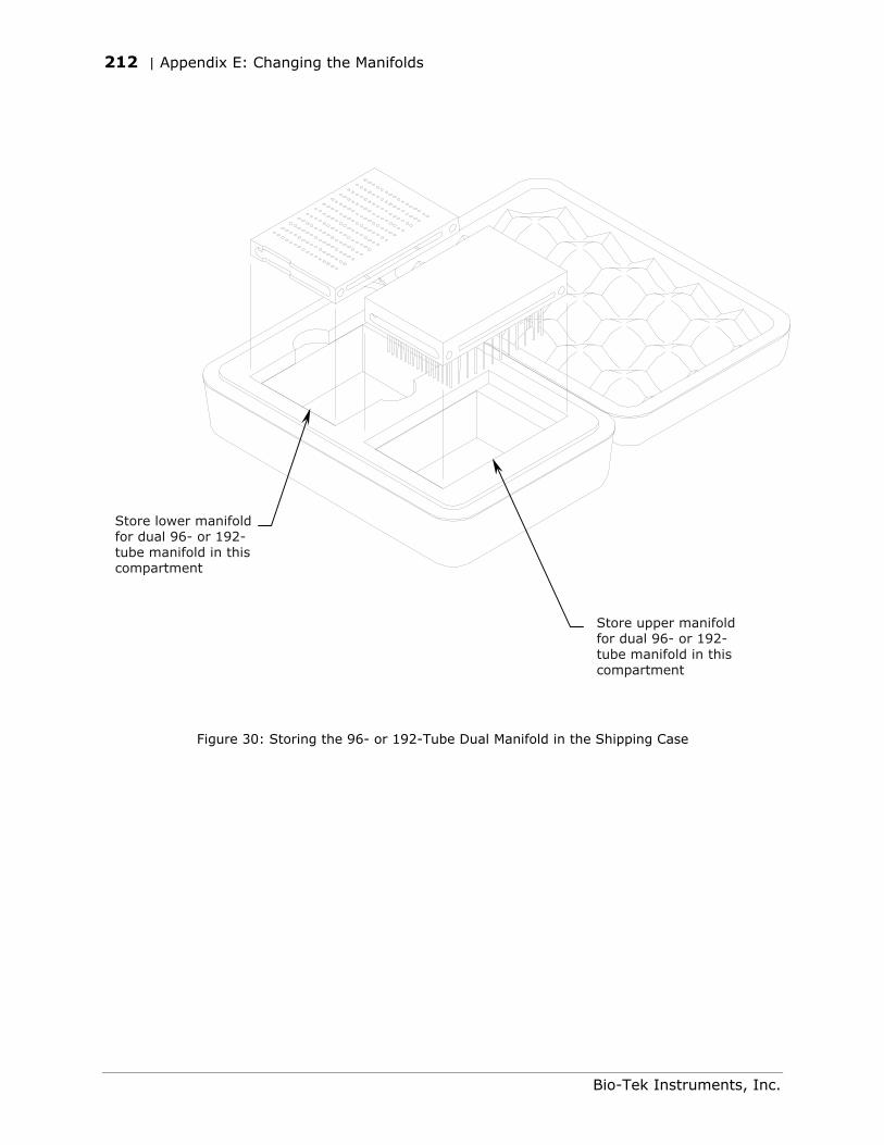
212 | Appendix E: Changing the Manifolds
Store lower manifold for dual 96- or 192-tube manifold in this compartment
Store upper manifold for dual 96- or 192-tube manifold in this compartment
Figure 30: Storing the 96- or 192-Tube Dual Manifold in the Shipping Case
Bio-Tek Instruments, Inc.
Index
A
Accessories
Optional, 9
Accessory 96-tube manifold, 3 Repackaging, 37
accuracy_qc_test, 153, 154, 155 Air bubbles in tubing, 50 Aspirate height, 62 Aspiration delay, 63, 66 Aspiration height, 62, 65 Aspiration program, 83
Copy aspiration program, 85
Define aspiration program, 84
Delete aspiration program, 85
Edit aspiration program, 84
Run aspiration program, 83
Aspiration rate, 63, 66 Assays
Cellular, 2
ELISA, 2
AUTOCLEAN Creating and running programs, 124, 125
Error codes, 198, 199
Warning, xix
AUTOPRIME, 110
B
Biohazards, xix Bio-Stack
Compatibility with washer, 2, 4
Installation with washer, 36
Operation with washer, 48
Bottles Cleaning, 115
Connection, 26
Bottom wash options, 58, 60 Bovine serum albumin, xxi, 112
C
Carrier
Cleaning, 115
Cleaning the transport arm, 116
Installation, 22
Magnetic plate carrier, 22
Cell washer, 3 Channel-end seals
Cleaning and replacing, 136
Part number, 104
Checksum Test, 145 Chemical compatibility
Components and materials composition, 206
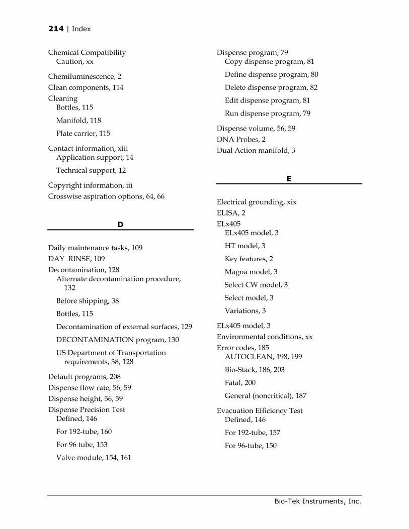
214 | Index
Chemical Compatibility Caution, xx
Chemiluminescence, 2 Clean components, 114 Cleaning
Bottles, 115
Manifold, 118
Plate carrier, 115
Contact information, xiii Application support, 14
Technical support, 12
Copyright information, iii Crosswise aspiration options, 64, 66
D
Daily maintenance tasks, 109 DAY_RINSE, 109 Decontamination, 128
Alternate decontamination procedure, 132
Before shipping, 38
Bottles, 115
Decontamination of external surfaces, 129
DECONTAMINATION program, 130
US Department of Transportation requirements, 38, 128
Default programs, 208 Dispense flow rate, 56, 59 Dispense height, 56, 59 Dispense Precision Test
Defined, 146
For 192-tube, 160
For 96 tube, 153
Valve module, 154, 161
Dispense program, 79 Copy dispense program, 81
Define dispense program, 80
Delete dispense program, 82
Edit dispense program, 81
Run dispense program, 79
Dispense volume, 56, 59 DNA Probes, 2 Dual Action manifold, 3
E
Electrical grounding, xix ELISA, 2 ELx405
ELx405 model, 3
HT model, 3
Key features, 2
Magna model, 3
Select CW model, 3
Select model, 3
Variations, 3
ELx405 model, 3 Environmental conditions, xx Error codes, 185
AUTOCLEAN, 198, 199
Bio-Stack, 186, 203
Fatal, 200
General (noncritical), 187
Evacuation Efficiency Test Defined, 146
For 192-tube, 157
For 96-tube, 150
Bio-Tek Instruments, Inc.
Index | 215
F
Fluid inlet filter
Cleaning, 126
Front panel, 42
G
General usage guidelines, 49
Before running any program, 49
Maintenance, 50
Programming considerations, 51
Grounding, xix
H
Hardware features, 6 Hazardous material, 38 High Flow vacuum pump
Caution, xxi
Installation, 28
Horizontal aspiration position, 62, 66 Horizontal dispense position, 57, 60 Horizontal Y aspiration position, 63, 66 Horizontal Y dispense position, 57, 60 HT model, 3
Changing the manifolds, 209
HT2 and HTV2 models, 3
Humidity warning, xix, 22
I
Installation Qualification (IQ), 142 Installation qualification package, 35 Intended use
Clinical, xviii
Research and development, xviii
Internal voltage, xix
K
Keypad
Description, 43
Entering program names, 44
L
Leaking
From external tubing connector, 181
From manifold, 181
From underneath washer, 181
Link programs, 88 Define link program, 89
Delete link program, 90
Run link program, 88
Liquid testing, 146 Dispense Precision Test, 153, 160
Evacuation Efficiency Test, 150, 157
Materials, 148
Solutions, 149
Which tests to perform, 147
Low vacuum, 175
ELx405 Operator's Guide
216 | Index
M
Magna model, 3 Magnet aspiration height, 62, 66 Main Menu, 46 Maintenance
Daily, 109
Overnight/multi-day, 111
Periodic, 114
RINSE_AND_SOAK program, 112
Maintenance programs, 106 DAY_RINSE, 109
OVERNIGHT_LOOP, 111
RINSE_AND_SOAK, 112
Manifold Cleaning, 118
Shipping bracket, 21
Mist shield Cleaning, 118
Installation, 33
O
Operating environment
Humidity, 22
Temperatures, 22
Operational qualification (OQ), 142 O-rings
Part number, 104
Replacing, 136
Overnight/multi-day maintenance tasks, 111
OVERNIGHT_LOOP, 111
P
Package contents, 8 Performance Qualification (PQ), 143 Performance specifications, 11 Performance verification
After installation, 35
Periodic maintenance tasks, 114 Plate carrier
Cleaning, 115
Plate type, 53 Plate type prompt, 84 Power Cord
Installation, 34
Prepare washer for storage/shipment, 134 Storage temperatures, 135
Preventive maintenance, 102 Defined, 102
Tasks and frequency, 103
Tools and supplies, 104
Warnings and precautions, 105
Prime after soak, 55 Prime flow rate, 55, 59, 61 Prime program, 73
Copy prime program, 77
Define prime program, 74
Delete prime program, 77
Edit prime program, 76
Prime_200, 78
Prime_CW, 78
Recommended prime and low flow prime volumes, 76
Run prime program, 73
Prime programs, 107 AUTOPRIME, 110
Bio-Tek Instruments, Inc.
Index | 217
Prime volume, 55, 59, 61 Problems
Aspiration tubes not entering well correctly, 182
Carrier/manifold position, 174
Display (LCD) not on, 173
Leaking, 181
Manifold position error, 182
Plate overfills, 179
Poor/uneven aspiration, 175
Scratches on microplate bottom, 183
Too much residual in wells, 177
Unable to dispense fluid, 178
Uneven dispensing, 180
Vacuum pump, 173
Programs Aspiration, 83
AUTOCLEAN, 123
DECONTAMINATION, 130
Dispense, 79
Link, 88
LONG_SHUTDOWN, 134
Prime, 73
RINSE_AND_SOAK, 112
Soak, 86
Wash, 52
Protein residuals BSA caution, xxi
Removing, 112
R
Registration
Card, xxviii
Online, xxviii
Regulations, 38 Remove magnet (during shake), 55 Repackaging and shipping
Washer, 37
Replace components, 136 Replace channel-end seals, 136
Replace o-rings, 136
residual_qc_test, 150 Restrictions and liabilities, iii Return Materials Authorization (RMA),
xviii, 12, 38 RIA, 2 Rinse/soak the fluid path, 109 RINSE_AND_SOAK program, 112 RS-232
Port, 34
S
Safety symbols, xxv Select CW model, 3 Select model, 3 Select reagent bottle prompt, 80 Self Test
At system startup, 45
Serial Communications, 34
Setup utilities, 91 Adjust utility, 92
Bio-Stack utilities, 93
Delay after dispense, 94
Manifold selection, 95
Park utility, 93
Plate clearance height, 94
RS-232 settings, 91
ELx405 Operator's Guide
218 | Index
Sensor system, 91
Vacuum dissipation delay, 94
Shipping Address for Bio-Tek, 13
Bracket removal/installation, xxi, 18, 21, 38
Preparing instrument for, 38
RMA, 38
Soak program, 86 Copy soak program, 87
Define soak program, 86
Delete soak program, 87
Edit soak program, 86
Soak/shake options, 54, 55 Software features, 7 Specifications, 10
Electrical, 10
Environmental, 10
Manifold type, 10
Microplates, 10
Physical, 10
Spilled fluids, xx Storing the washer, 135 Supply system
Installation, 30
Symbols, using in program name, 44 System Self Test, 144
T
TAC, 12 Technical assistance center, 12 Tests
Checksum Test, 145
Dispense Precision, 192-tube, 160
Dispense Precision, 96-tube, 153
Evacuation Efficiency, 192-tube, 157
Evacuation Efficiency, 96-tube, 150
System Self Test, 144
Troubleshooting, 171 Charts, 173
Checklist, 172
Fluid aspiration, 175
Fluid delivery, 178
Fluid leakage, 181
Microplate carrier movement, 182
Microplate scratches, 183
Washer manifold movement, 182
Washer Start-Up, 173
Tubes Installation of, 26
Tubing Air bubbles, 50
Cleaning, 118
Typographic conventions, xiv
U
Ultrasonic Advantage, 2, 123
Models, 3
Unpacking Valve module, 19
Washer, 16
V
Vacuum
Low, 175
Bio-Tek Instruments, Inc.
Index | 219
Vacuum on volume, 56, 59 Valve module, external
Attaching to washer, 30
Compatibility with washer models, 2, 3
Dispense Precision Test, 154, 161
Repackaging and shipping, 39
Unpacking, 19
Verification schedule, 141 Voltage, xix
W
Warranty, xxvii
Conditions for voiding, 16, 21
Wash format, 54, 55 Wash program, 52
Copy wash program, 71
Define wash aspirate program options, 62
Define wash dispense program options, 56
Define wash method program options, 54
Define wash program, 53
Delete wash program, 72
Edit wash program, 71
Run wash program, 52
Washer menu maps, 96 Waste sensor port
Caution, xxi
Waste system Installation, 28
ELx405 Operator's Guide

220 | Index
Bio-Tek Instruments, Inc.