Embed Size (px)
Citation preview

OM673L3For Models: M673L3, M673LG, M673LD3
and M673LD3G
OPERATOR’S MANUALOPERATOR’S MANUAL
www.northern-lights.com

Breathing Diesel engine exhaust and some of its constituents are known to the State of California to cause cancer, birth defects, and other reproductive harm.* Always start and operate the engine in a well-ventilated area.* If in an enclosed area, vent the exhaust to the outside.* Do not modify or tamper with the exhaust system.* Do not idle the engine except as necessary.For more information, go to www.P65warnings.ca.gov/diesel.
— CALIFORNIA —Proposition 65 Warning:
Northern Lights4420 14th Avenue NWSeattle, WA 98107Tel: (206) 789-3880Fax: (206) 782-5455
Copyright ©2018 Northern Lights, Inc.All rights reserved. Northern Lights™, andthe Northern Lights logo are trademarks ofNorthern Lights, Inc.
Printed in U.S.A.PART NO.: OM673L3 10/18
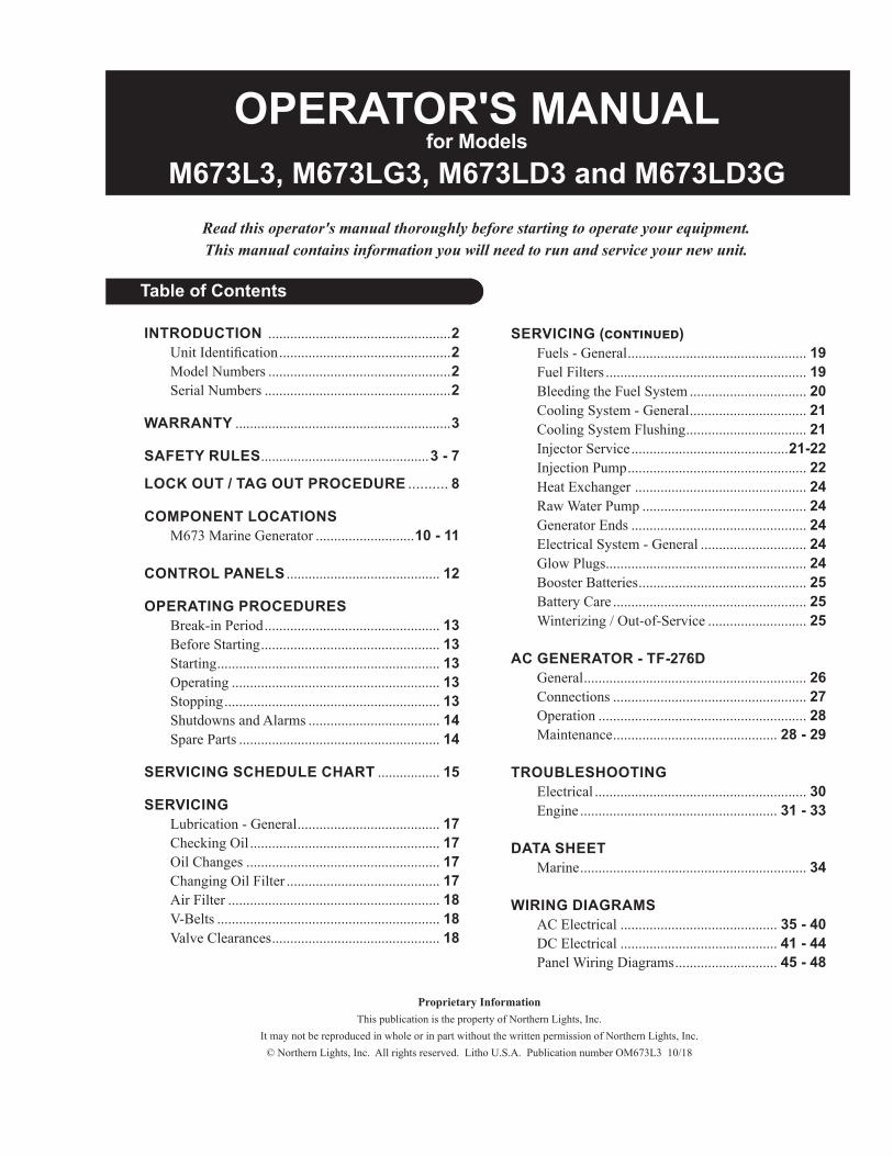
Read this operator's manual thoroughly before starting to operate your equipment.This manual contains information you will need to run and service your new unit.
OPERATOR'S MANUALfor Models
M673L3, M673LG3, M673LD3 and M673LD3G
Table of Contents
INTRODUCTION ..................................................2 UnitIdentification ...............................................2 ModelNumbers ..................................................2 SerialNumbers ...................................................2
WARRANTY ...........................................................3
SAFETY RULES ..............................................3 - 7
LOCK OUT / TAG OUT PROCEDURE .......... 8
COMPONENT LOCATIONS M673MarineGenerator ...........................10 - 11 CONTROL PANELS .......................................... 12
OPERATING PROCEDURES Break-inPeriod ................................................ 13 BeforeStarting ................................................. 13 Starting ............................................................. 13 Operating ......................................................... 13 Stopping ........................................................... 13 ShutdownsandAlarms .................................... 14 SpareParts ....................................................... 14
SERVICING SCHEDULE CHART ................. 15
SERVICING Lubrication-General ....................................... 17 CheckingOil .................................................... 17 OilChanges ..................................................... 17 ChangingOilFilter .......................................... 17 AirFilter .......................................................... 18 V-Belts ............................................................. 18 ValveClearances .............................................. 18
SERVICING (continued) Fuels-General ................................................. 19 FuelFilters ....................................................... 19 BleedingtheFuelSystem ................................ 20 CoolingSystem-General ................................ 21 CoolingSystemFlushing ................................. 21 InjectorService ...........................................21-22 InjectionPump ................................................. 22 HeatExchanger ............................................... 24 RawWaterPump ............................................. 24 GeneratorEnds ................................................ 24 ElectricalSystem-General ............................. 24 GlowPlugs ....................................................... 24 BoosterBatteries .............................................. 25 BatteryCare ..................................................... 25 Winterizing/Out-of-Service ........................... 25
AC GENERATOR - TF-276D General ............................................................. 26 Connections ..................................................... 27 Operation ......................................................... 28 Maintenance ............................................. 28 - 29
TROUBLESHOOTING Electrical .......................................................... 30 Engine ...................................................... 31 - 33
DATA SHEET Marine .............................................................. 34 WIRING DIAGRAMS ACElectrical ........................................... 35 - 40 DCElectrical ........................................... 41 - 44 PanelWiringDiagrams ............................ 45 - 48
Proprietary InformationThispublicationisthepropertyofNorthernLights,Inc.
ItmaynotbereproducedinwholeorinpartwithoutthewrittenpermissionofNorthernLights,Inc.©NorthernLights,Inc.Allrightsreserved.LithoU.S.A.PublicationnumberOM673L310/18

OM673L3 10/18
2
Servicingofmarineenginesandgeneratorsetspresentsuniqueproblems.Inmanycasesboatscannotbemovedtoarepairfacility.Marineenginescannotbecomparedtotheservicingofautomobiles,trucksorevenfarmequipment.Failuresoftenoccurinremoteareasfarfromcompetentassistance.Marineenginesaretaxedfarmoreseverelythanautoortruckengines;therefore,maintenanceschedulesmustbeadheredtomorestrictly.
Failuresbeginwithminorproblemsthatareoverlookedandbecomeamplifiedwhennotcorrectedduringroutinemaintenance.
Asoperator,itisyourobligationtolearnaboutyourequipmentanditspropermaintenance.Thisisnotacomprehensivetechnicalservicemanual.Norwillitmakethereaderintoanexpertmechanic.Itsaimistoaidyouinmaintainingyourunitproperly.
Introduction
Serial Numberss
MODELS INCLUDEDThismanualcoverstheoperatinginstructionsfor: M673L3 and M673LD3 marine generator sets.
Model Numbers
Modelnumbersgivetheunit'sapplication,blockmodel,aspiration,andRPM:
Unit Identification
Northern Lights marine diesel generator set with a 673 engine long stroke, TF-276D generator end, US EPA Tier III, 6 kW.M673L3 =
Northern Lights marine diesel generator set with a 673 engine long stroke, TF-276D generator end, GEM series, US EPA Tier III, 5 kW.
M673LD3G =
Yoursethasthreeserialnumbers:1anenginenumberstampedontheblock,2ageneratorplate,and 3 ageneratorsetplate.
Usetheserialnumberonthegeneratorsetplatewhenorderingpartsorincorrespondence.ThegeneratorsetplateisfoundontheservicesideofthegeneratorandresemblesthedrawinginFigure 1.
Note,anadditionallabelwiththesetserialnumberisplacedontheupperfrontcornerofthegeneratorjunctionbox.
Updated 3-9-18
L, D, G, 3
M - Northern Lights marine generator set
Model number of engine block Bore Cylinders 67 mm 3
L - Long strokeD - Series designationG - GEM series base frame3 - US EPA Tier III compliant
+ +
M 673

OM673L3 10/18
3
Awarrantyregistrationcertificateissuppliedwithyourset.Itentitlestheoriginalpurchaserofourequipmenttoawarrantycoveringmaterialorassemblyfaults.TheextentofcoverageisdescribedintheLimitedWarrantyStatement.Werecommendthatyoustudythestatementcarefully.NOTE:Ifthewarrantyistoapply,theservicinginstructionsoutlinedinthismanualmustbefollowed.Iffurtherinformationisneeded,pleasecontactanauthorizeddealerorthefactory.
Safety Rules
Warranty
NOTICE: Accident reports show that careless use of engines causes a high percentage of accidents. You can avoid accidents by observing these safety rules. Study these rules carefully and enforce them on the job.
IMPORTANTSAFETYINSTRUCTIONS.Electromagneticequipment,includinggeneratorsetsandtheiraccessories,cancausebodilyharmandlifethreateninginjurieswhenimproperlyinstalled,operatedormaintained.Topreventaccidentsbeawareofpotentialdangersandactsafely.
READANDFOLLOWALLSAFETYINSTRUCTIONSINTHISMANUAL,PRIORTOTHEINSTALLATIONOFANYGENERATORSETORACCESSORY.KEEPTHESEINSTRUCTIONSFORFUTUREREFERENCE.
Recognize Safety Symbols and InstructionsInadditiontotheinformationfoundinthissection,thisoperator’smanualusesthreedifferentsignalwordstooutlinepotentialdangersofaspecificnature.
Follow All Safety InstructionsCarefullyreadandunderstandallsafetymessagesinthismanualandonyourmachine’ssafetysigns.Keepsignsingoodandcleancondition.Replacemissingordamagedsigns.Besurenewequipmentcomponentsand
repairpartsincludethecurrentsafetysigns.Forreplacementsigns,properplacementofsafetysignsorclarificationonanysafetyissue,consultyourNorthernLightsdealerorthefactory.Therecanbeadditionalsafetyinformationcontainedonpartsandcomponentsfromoutsidesuppliersthatisnotreproducedinthismanual.Consultthesuppliersforadditionalsafetyinformation.
Learnhowtooperatethemachineandhowtousethecontrolsproperly.Onlytrainedpersonnelshouldoperatemachines,orworkonoraroundthem.
Keepyoumachineinproperworkingcondition.UNAUTHORIZEDMODIFICATIONSTOTHEMACHINERYMAYIMPAIRITSFUNCTIONANDSAFETYPARAMETERS.
Prevent Bypass and Accidental Starting
! WARNINGDonotstartenginebyshortingacrossstartterminal.Enginewillstartifnormalcircuitryisbypassed,creatingahazardbyrunawaymachinery.
Startengineonlyfromoperator’sstation.
! DANGER! WARNING! CAUTION
DANGERindicatesahazardoussituationwhich,ifnotavoided,willresultindeathorseriousinjury.
WARNINGindicatesahazardoussituationwhich,ifnotavoided,couldresultindeathorseriousinjury.
CAUTIONindicatesahazardoussituationwhich,ifnotavoided,couldresultinminorormoderateinjury.
DANGER: Northern Lights generator sets and /or any other diesel powered equipment provided by NLI is not provided with spark arresting or explosion proof components, and therefore is not to be installed in the presence of combustible gases having a flash point of 43.3 Degrees C (110 Degrees F) or lower, such as Gasoline, Propane, Natural Gas or other similar fuel sources.
Updated 4-12-17

OM673L3 10/18
4
Safety Rules (Continued)
Wear Protective Clothing
! WARNINGTopreventcatchinganythinginmovingmachinery,alwayswearclosefittingclothesandsafetyequipmentappropriatetothejob.Prolongedexposuretoloudnoisecancausehearinglossorimpairment.Wearsuitableauthorizedhearingprotection,suchasearmuffsorplugstoprotectagainstloudnoises.
Operatingequipmentrequiresthefullattentionoftheoperator.Donotuseradioormusicheadphoneswhileoperatingmachinery.Practice Safe Maintenance
! CAUTIONUnderstandallserviceproceduresbeforestartingwork.Keepareacleananddry.Neverlubricate,service,oradjustmachinewhileitisinoperation.
Keephands,feetandclothingawayfrompower-drivenequipment.Whenshuttingdownanengine,disengageallpowerandoperatorcontrols.Allowtheenginetocoolcompletelybeforebeginninganyservicework.
Securely support any machinery elements that must be raised for service work with support or lifting machinery specifically intended for that purpose.
Keepallpartsingoodconditionsandproperlyinstalled.Fixdamageimmediately.Replaceanywornorbrokenparts.Removeanybuildupofgrease,oilordebris.
Disconnectbatterygroundcable(-)beforemakinganyadjustmentsorservicework.
Handle Fuel Safely - Avoid Flames
! WARNINGDieselishighlyflammableandshouldbetreatedwithcareatalltimes.Dodonotrefuelwhilesmokingorwhennearsparksoropenflame.
ALWAYSSTOPENGINEBEFOREFUELINGMACHINE.Alwaysfillportablefueltankoutdoors.Neverfuelahotengine.Preventaccidentaldischargeofstartingfluidsbystoringallcansinacool,safeplace,awayfromsparksoropenflame.Storewithcapsecurelyoncontainer.Neverincinerateorpunctureafuelcontainer.
Preventfiresbykeepingmachinecleanofaccumulatedtrash,greaseanddebris.Alwayscleananyspilledfuelasswiftlyaspossible.Donotstoreoilyrags,whichcanigniteandburnspontaneously.
Bepreparedifafirestarts.Keepafirstaidkitandfireextinguisherhandy.Keepemergencycontactnumbersforfiredepartment,doctors,ambulanceandhospitalnearthetelephone.
Service Machines Safely
! DANGERDonotwearanecktie,scarf,necklace,ringsorotherjewelry,oranylooseclothingwhenworkingnearmovingparts.Tielonghairbehindyourhead.Ifanyoftheseitemsgetcaughtinmovingmachinery,severeinjuryordeathcouldresult.
Checkforanylooseelectricalconnectionsorfaultywiring. Lookcompletelyaroundenginetomakesurethateverythingisclearbeforestarting.
Updated 4-12-17

OM673L3 10/18
5
Stay Clear of Rotating Drivelines
! DANGEREntanglementinrotatingdrivelinescancauseseriousinjuryordeath.Keepshieldsinplaceatalltimes.Makesurethatrotatingshieldsturnfreelyinpacewiththedrivelines.
Donotwearloosefittingequipmentaroundrotatingdrivelines.Stoptheengineandmakesurethatallmovingpartshavestoppedbeforemakinganyadjustments,connections,orperforminganyothertypeofservicetotheengineorotherdrivenequipment. Install all Safety Guards
! WARNINGDirectcontactwithrotatingfans,belts,pulleyanddrivescancauseseriousinjury.
Keepallguardsinplaceatalltimesduringengineoperation.
Wearclose-fittingclothes.Stoptheengineandbesureallfans,belts,pulleysanddrivesarestoppedbeforemakingadjustments,connections,orcleaningnearfansandtheircomponents.
Donotallowanythingonyourpersontodangleintoorcomeincontactwithamovingfan,belt,pulleyordrive.Fanscanactasvacuumsandpullmaterialsupfrombelow,soavoidthatareaaswellwhileinservice.
Safe Battery Handling
! WARNINGPrevent Battery Explosions Batterygasishighlyflammable.Batteryexplosionscancausesevereinjuryordeath.Tohelppreventbatteryexplosions,keepsparks,lightedmatchesandopenflameawayfromthetopofbattery.Whencheckingbatteryelectrolytelevel,useaflashlight.
Safety Rules (Continued)
Nevercheckbatterychargebycontactingthepostswithametalobject.Useavolt-meterorhydrometer.
Frozenbatteriesmayexplodeifcharged.Neverchargeabatterythathasnotbeenallowedtowarmtoatleast16oC(60oF).Alwaysremovegrounded(-)batteryclampfirstandreplacegroundclamplast.
Sulfuricacidinbatteryelectrolyteispoisonousandstrongenoughtoburnskin,eatholesintoclothingandothermaterials,andcauseblindnessifsplashedintoeyes.
To Avoid Hazards:•Fillbatteriesonlyinwell-ventilatedareas.•Wearappropriateeyeprotectionandrubbergloves.•Neveruseairpressuretocleanbatteries.•Wearappropriateventilationequipmenttoavoidinhalingfumeswhenaddingelectrolyte.•Donotspillordripelectrolyte.•Usecorrectjump-startprocedureifrequired.
If acid is spilled on skin or in eyes:1.Flushskinwithwater.2.Applybakingsodaorlimetohelpneutralizeacid.3.Flusheyeswithwaterfor15-30minutes.4.Getmedicalattentionimmediately.Ifacidisswallowed:1.DONOTinducevomiting.2.Drinklargeamountsofwaterormilk,withoutexceeding2liters(2quarts)3.Getmedicalattentionimmediately
Batteryposts,terminals,andrelatedaccessoriescancontainleadandleadcompounds,chemicalsknowntotheStateofCaliforniatocausecancerandreproductiveharm.Washhandsafterhandling.
! WARNING
Updated 4-12-17

OM673L3 10/18
6
Safety Rules (Continued)Donotuseachlorinatedsolventinanareawhereweldingwilloccur.Workonlyinareasthatarewellventilated.Disposeofpaintandsolventproperly.
Service Cooling System Safely
! WARNINGOpeningapressurizedcoolingsystemcanreleaseexplosivefluidsandcausingseriousburns.Beforeopeninganypressurizedcoolingsystem,makesuretheenginehasbeenshutoff.Donotremoveafillercapunlessitiscoolenoughtocomfortablygripwithbarehands.Slowlyloosencaptorelievepressurebeforeopeningfully.
Avoid High Pressure Fluids
! WARNINGRelievepressurepriortodisconnectingpressurizedlines.Escapingfluidunderpressurecanpenetratetheskincausingseriousinjury.Alwaysrelievepressurebeforedisconnectinghydraulicorotherpressurizedlines.Tightenallconnectionsfirmlybeforere-applyingpressure.
Ifsearchingforleaks,useapieceofcardboard.Alwaysprotectyourhandsandotherbodypartsfromhigh-pressurefluids.
Ifanaccidentoccurs,seeadoctorimmediately.Anyhighpressuresprayinjectedintotheskinmustberemovedwithinafewhourstopreventtheriskofgangreneorotherinfection.
Avoid Heating Near Pressurized Fluid Lines
! WARNINGFlammablespraycanbegeneratedbyheatingnearpressurizedfluidlines,resultinginsevereburnsandbodilyinjury.Pressurizedlinescanrupturewhenheatgoesbeyondtheimmediateflamearea.Donotweld,solderoruseatorchoropenflamenearpressurizedlinesorotherflammablefluids.
Handle Chemical Products Safely
! WARNINGDirectexposuretohazardouschemicalscancauseseriousinjury.AmongthepotentiallyhazardouschemicalsthatmaybeusedwithNorthernLightsproductsarelubricants,coolants,paintsandadhesives.
AllpotentiallyhazardouschemicalscomewithaMaterialDataSafetySheet(MSDS).TheMSDSprovidesspecificdetailsonchemicalproducts,includingphysicalhazards,safetyproceduresandemergencyresponsetechniques
ReadandunderstandtheMSDSforeachchemicalbeforeyoustartanyjobthatincludesit.Followtheproceduresanduseappropriateequipmentexactlyasrecommended.
ContactyourNorthernLightsdealerorNorthernLightsfactoryforMSDS’susedonNorthernLightsproducts.
Work in Well Ventilated Areas
! CAUTIONExhaustfumesfromenginescontaincarbonmonoxideandcancausesicknessordeath.Workinwellventilatedareastoavoidprolongedexposuretoenginefumes.Ifitisnecessarytorunanengineinanenclosedarea,routetheexhaustfumesoutoftheareawithanapproved,leakproofexhaustpipeextension.
Remove Paint Before Welding or Heating
! WARNINGHazardousfumescanbegeneratedwhenpaintisheatedbywelding,solderingorusingatorch.Toavoidpotentiallytoxicfumesanddust,removepaintbeforeheating.• Removepaintaminimumof100mm(4in.)fromtheareathatwillbeaffectedbyheat.• Ifpaintcannotberemoved,wearanapprovedrespirator.•Ifyousandorgrindpaint,useanapprovedrespirator.•Ifyouusesolventorpaintstripper,removestripperwithsoapandwaterbeforewelding.Removesolventorpaintstrippercontainersfromthearea.•Allowatleast15minutesforfumestodispersebeforeweldingorheating.
Updated 4-12-17

OM673L3 10/18
7
Safety Rules (Continued)
Avoidcreatingdust.Neverusecompressedairforcleaning.Avoidbrushingorgrindingmaterialscontainingasbestos.Whenservicing,wearanapprovedrespirator.Aspecialvacuumcleanerisrecommendedtocleanasbestos.Ifthisvacuumisnotavailable,applyamistofoilorwateronthematerialcontainingasbestos.Keepallbystandersawayfromanyareawhereasbestosdustmaybegenerated.
Use Proper Lifting Equipment and Techniques
! WARNINGLiftingheavycomponentsincorrectlycancausesevereinjuryordamagetomachinery.Avoidunbalancedloads.Donotuseliftingeyes.Liftthegeneratorsetusingliftingbarsinsertedthroughtheliftingholesontheskid.FollowallrecommendedremovalandinstallationproceduresinthisandassociatedNorthernLightsmanuals.
Use Proper Tools
! CAUTIONMakeshifttoolsandprocedurescancreatesafetyhazards.Alwaysuseappropriatetoolsforthejob.
Usepowertoolsonlytoloosenthreadedpartsandfasteners.Forlooseningandtighteninghardware,alwaysusethecorrectsizedtools.
DonotuseUSmeasurementtoolsonmetricfasteners,orviceversa.UseonlyservicepartsthatmeetNorthernLightsspecifications.
Dispose of Waste Properly
! CAUTIONDisposingofwasteimproperlycanthreatentheenvironmentandleadtounsafeworkingconditions.PotentiallyharmfulwasteusedinNorthernLightsequipmentcanincludeoil,fuel,coolant,filtersandbatteries.
Useleakproofcontainerstodrainfluid.Donotusefoodorbeveragecontainersthatmaymisleadsomeoneintodrinkingfromthem.
Donotpourwasteontotheground,downadrainorintoanywatersource.
Do Not Open High-Pressure Fuel System
! DANGERManyNorthernLightsenginesusehigh-pressurefuelinjection.High-pressurefluidremaininginfuellinescancauseseriousinjury.Donotdisconnectorattemptanyrepairoffuellines,sensors,orother
componentsbetweenthehigh-pressurefuelpumpandnozzlesonengineswithhighpressurefuelsystems.
ONLYAUTHORIZEDTECHNICIANSCANPERFORMREPAIRSONANHIGHPRESSUREFUELINJECTIONSYSTEMS.
Avoid Hot Exhaust
! WARNINGAvoidexposuretoandphysicalcontactwithhotexhaustgases.Exhaustpartsandstreamscanreachhightemperaturesduringoperation,leadingtoburnsorotherseriousinjury.
Cleaningexhaustfilterscanalsoleadtoexposuretohotexhaustgasandtheinjuryriskassociatedwithit.Avoidexposuretoandphysicalcontactwithhotexhaustgaseswhencleaningexhaustfilters.
Duringautoormanual/stationaryexhaustfiltercleaningoperations,theenginewillrunatelevatedtemperaturesforanextendedperiodoftime.Exhaustpartsandstreamscanreachhightemperaturesduringoperation,leadingtoburnsorotherseriousinjury.
Avoid Harmful Asbestos Dust
! WARNINGInhalingasbestosfibersmaycauselungcancer.Avoidbreathinganydustthatmaybegeneratedwhenhandlingcomponentscontainingasbestosfibers,includingsomegaskets.
Theasbestosusedinthesecomponentsisusuallyfoundinaresinorotherwisesealed.Normalhandlingofthesecomponentsisnotdangerous,aslongasairbornedustcontainingasbestosisnotgenerated.
Updated 4-12-17

OM673L3 10/18
8
General Policy
To avoid dangerous or hazardous situations, refrain from any of the following:• Removing or bypassing a guard or other safety device• Placing any part of your body in a position where you could be caught by moving machinery.• Cleaning or oiling machinery when in operation.• Adjusting circuits, chillers, pumps, air handlers, valves, circuit breakers or fans while in operation.• Working on piping or high pressure systems.
Lock Out/Tag Out Instructions - Electrical Equipment
Be sure the equipment’s ON/OFF switch is in the OFF position and is unplugged from any electrical source before attempting to perform any type of work on the equipment. Obtain an electrical plug cap cover with a lockset. Secure the plug terminal end using the electrical plug lockout cap. Lock the cap and retain the key.
If the equipment is directly wired into an electrical box with a shut off switch, obtain a lock pad and/or the appropriate colored tags and place the lock and tag through the shut off lever. Retain the key until the repair is completed and the machine is safe to start. Be certain the shut off lever is in the OFF position before restarting. NEVER give a lock out key to unauthorized personnel.
If the equipment is directly wired into an electrical box without a shut off switch and lock out capability, then a circuit breaker lock out will be required. Obtain a circuit lock and tag set. Install the lock onto the circuit breaker box. Ensure the unit ON/OFF switch is in the OFF position before restarting.
Lock Out/Tag Out Instructions - Pneumatic and Hydraulic Equipment
For servicing pneumatic and hydraulic equipment, the following additional procedures must be implemented, following completion of lock out/tag out procedures for the unit to be serviced:
Shut off air, water or supply valves at the equipment to be serviced.
Check the local bleed-off point for completed release of pressurized air, water or oil.
If shutting off of air, water or other material cannot be achieved at the local supply valve, shut off valves further back in the system and re-check the bleed-off point until complete shut-off is achieved.
Affix a DO NOT OPERATE tag to each valve handle that requires shut off. Each DO NOT OPERATE tag must be signed and dated by the authorized technician servicing the equipment.
Lock Out/Tag Out Instructions - Air Hose Connected Pneumatic Equipment
Equipment connected to the compressed air system through an air hose with a detachable fitting must be shutdown and unplugged. Excess air must be bled prior to removing the air hose, prior to any maintenance or repair activities.
Affix a DO NOT OPERATE tag to the air hose near the detachable fitting. Each DO NOT OPERATE tag must be signed and dated by the authorized technician servicing the equipment. Check that the equipment cannot be operated by activating the ON switch.
Stored Energy
Immediately after applying Lock Out or Tag Out devices, ensure that all potentially hazardous stored or residual energy is relieved, disconnected, restrained and otherwise rendered safe.
Verification of Isolation
Verify the machinery or equipment is actually isolated and de-energized prior to beginning work on a machine or on equipment that has been locked out.
Restarting Procedures
Follow the procedures below prior to restoring energy:• Ensure that all machinery or equipment is properly reassembled. Inspect the machinery or equipment to verify non-essential items have been removed.• Ensure that all personnel are safely outside danger zones. Notify personnel that lock out/tag out devices have been removed and energy will be reapplied.• Only authorized personnel may remove lock out/tag out devices or notices.
ScopeDuring maintenance, repairs or retooling of a Northern Lights generator set, simply turning the machine off or unplugging it while it is being worked on does not give enough protection to others who are not performing the maintenance or repair. Many serious accidents happen when someone thought the machine was turned off, or all of its energy was safely blocked or released.
! CAUTION
! WARNING
! WARNING
! WARNING
! WARNING
! CAUTION
! CAUTION
Lock Out / Tag Out Procedures
Updated 4-12-17
OM673L3 10/18
9
Notes

OM673L3 10/18
10
1. Generator junction box 2. AVR circuit breaker 3. AC circuit breaker 4. DC circuit breaker 5. Air filter housing 6. Secondary fuel filter 7. Oil fill, top 8. Coolant fill, pressure cap
17. Fuel inlet and return18. Coolant recovery bottle19. Control panel plug-in 20. Heat exchanger end cap 21. Heat exchanger/ expansion tank/ expansion manifold
9. Fuel injector 10. Fuel injection pump 11. Fuel lift pump12. Sea water pump13. Lube oil drain 14. Oil fill, side15. Lube oil dipstick 16. Primary fuel filter
22. Starter motor 23. Exhaust elbow 24. Vibration mount25. DC regulator26. DC alternator 27. Belt guard
Marine Generator Component Locations
2
1
3 45 6
78
9
10
1112
13
1415
161718
19
Figure 1 (left): Service side M673L3G/LD3G w/GEM Series base frame (S/N: 6732-54637 and above)
Figure 2 (right): Non-service side M673L3G/LD3G w/GEM Series frame (S/N: 6732-54367 and above)
20 2021 22
23
24
26
27
25
Updated 3-13-18

OM673L3 10/18
11
1. Heat Exchanger End Cap 2. Coolant Fill/Pressure Cap 3. Heat Exchanger/Expansion Tank/Exhaust Manifold 4. Lube Oil Fill- Top 5. Wet Exhaust Elbow 6. Generator Junction Box 7. Control Panel Plug-In
16. DC Circuit Breaker 17. Air Filter Housing18. Fuel Filter 19. Fuel Injector 20. Fuel Injection Pump 21. Fuel Lift Pump 22. Sea Water Pump
8. Generator End Cover 9. Vibration Mount 10. Starter Motor 11. DC Regulator12. DC Alternator 13. Belt Guard14. AVR Circuit Breaker15. AC Circuit Breaker
23. Lube Oil Drain24. Lube Oil Fill- Side25. Block Drain 26. Lube Oil Dipstick27. Lube Oil Filter28. Fuel Inlet and Return29. Coolant Recovery Tank
Marine Generator Component Locations
1 12 3 4 5 6
7
8
91011
12
13
29
14 15 174 2 19
20
18
21
22
23
16
24
26 252728
Figure 3 (left): Service side M673L/LD3 (up to S/N: 6732-54636)
Figure 4 (right): Service side M673L/LD3 (up to S/N: 6732-54636)
Updated 3-13-18

OM673L3 10/18
12
Figure 5: Series 3 Generator Control Panel
Figure 4: Series 1-B Generator Control Panel
Figure 6: Series 4 Generator Control Panel
1. SHUTDOWN BYPASS-PREHEAT SWITCH Thisswitchservestwofunctions: 1.Preheatsglowplugsbeforebeginningthestartingprocess.Pressswitchfor10-20seconds
beforeattemptingstart-up. 2.Bypassesthesafetyshutdownfeatureduringthe
startingprocess.Keepswitchengagedwhilestartingengine,andfor2to3secondsafterwards,allowingoilpressuretobuildbeyondshutdownsetpoint.
2. ENGINE CONTROL SWITCH Tostarttheengine,holdthisswitchintheSTART
positionuntiltheengineisrunning. NOTE: Excessive cranking of marine sets equipped with water lift muffler systems can cause engine
damage. See page 7. Aftertheenginestarts,releasetheswitchanditwill
returntoRUNposition.Tostoptheengine,presstheswitchtotheSTOPposition.
NOTE: The rocker switch is used on Series 1 panels only, and has a light that glows when the set is running.
3. HOUR METER Keepstrackofenginerunningtime.
4. OIL PRESSURE GAUGE Showstheoilpressureintheenginelubricatingsystem.
5. WATER TEMPERATURE GAUGE Registersthetemperatureofthecoolingwater.
6. D.C. VOLTMETER Whentheengineisrunning,thevoltmeterindicatesthe
voltageoutputofthealternator.
For Series 4 Control Panels Only:
7. A.C. VOLTMETER Showsthegeneratoroutputvoltage.
8. FREQUENCY METER (Hertz) Thefrequencymeterindicatesenginespeed:1800RPM(60Hz),or1500RPM(50Hz).
9. AMMETER SELECTOR SWITCH Usedtocheckeachphaseforloadcondition. NOTE: Always leave this switch in the ON position
while the unit is running.
10. A.C. AMMETER Showsthegeneratorloadoneachphase.Thephaseis
selectedwiththeAmmeterSelectorswitch(Item 9).
Control Panels
Updated 6-24-10

OM673L3 10/18
13
BREAK-IN PERIOD
1. Thefirst100hoursonaneworreconditioned enginearecriticaltoitslifeandperformance.2. Operatetheengineundervariousconditions,
particularlyheavyloadswithminimalidling,tohelpseatenginecomponentsproperly.
3. Constantlychecktheenginetemperatureandoilpressuregauges(setswithSeries3or4panels).
4. Oilconsumptionisgreaterduringbreak-inas pistonringstaketimetoseat.5. Break-InOilChanges:Changeengineoiland filterat50hours.Changeoilandfilteragainat 100hours,thenatevery250hours(consult Lubricantssectionforoilrecommendation).
BEFORE STARTING
1. Checkthewaterlevelbyremovingthepressure capfromtheexpansiontankorradiator.Inorderto
givethecoolingwateranopportunitytoexpand,thelevelshouldbeabout1in.(2.5cm)belowthefillercapsealingsurfacewhentheengineiscold.Ifusinganoverflowbottle,themanifoldshouldbefulltothecapandthebottleshouldhavecoolantinit.
CAUTION: Use protective clothing and open the filler cap carefully when the engine is warm to prevent burns.
2. Checktheoillevelinthecrankcasewiththe dipstick.Theoillevelmustbeinthewaffledareaon
thestick.Neverallowtheleveltogobelowthisarea.Alwaysaddthesameviscosityofoilasisalreadyinthecrankcase.
3. Checkthefueltanklevelandopenanyfuelvalves.4. Closethesea-cock,checkandcleantheseastrainer
andreopenthesea-cock.5. PlacethebatteryswitchintheONposition. NOTE: The battery switch must always be kept ON while the engine is running. If the switch is
turned OFF while the engine is running, the battery charging regulator could be ruined.
STARTING
1. HoldtheShutdownBypass-PreheatswitchintheONpositionfor10to20secondsbeforestartingacoldengine.Holdingtheswitchtoolongcanburnouttheglowplugs.
2. WhileholdingtheShutdownBypass-PreheatswitchintheONposition,pushtheEngineControlswitchtotheSTARTposition.
3. Assoonastheenginestarts,releasethestartswitch.Thenholdthebypassfor2-3moreseconds.Donotcrankthestarterformorethan10secondsconsecutively.Iftheenginefailstostartwiththefirstattempt,besurethatithasstoppedcompletelybeforere-engaging.
NOTE: Excessive cranking of the starter on Marine sets equipped with a water lift muffler can cause engine damage. If the engine does not start after three 10-second cranks, remove the impeller from the raw water pump. This will prevent the muffler from filling with water and backfilling the exhaust line and engine. Once the engine starts, shut it off immediately and re-install the impeller. Re-start the engine and check the exhaust overboard outlet for gushes of water.
OPERATING
1. UnitswithSeries3andSeries4ControlPanels:checkgaugesoften.Oilpressuremustbeabove15PSI.TheD.C.voltmetershouldreadbetween11and15voltsat80°F(25°C)ambienttemperature.Thecoolanttemperaturegaugemustbebetween167°Fand194°F(75°Cto90°C).ChecktheA.C.voltageandfrequencymeters(Series4panel).Ifthegaugesdeviatefromnormallevels,shutdownthegeneratorsetandinvestigate.
2. Lettheunitrununloadedfora3-5minutewarm-upperiod.
3. Addelectricalload.
STOPPING
1. Removeelectricalloadfromthegeneratorset.2. Runtheenginefora3to5minutecooldownperiod.3. MovetheEngineControlswitchtotheSTOP positionmomentarily.4. Shutofftheseacock,fuelvalve,andbatteryswitch.
Operating Procedures
Updated 1-9-13

OM673L3 10/18
14
Operating Procedures
SHUTDOWNS AND ALARMS
1. Generatorsetshaveshutdownsystemstostopthe engineintheeventofhighwatertemperatureorlow
oilpressure. a. Otheralarmsandshutdownsareavailableas optionalequipment. NOTE: Do not rely on your warning to the exclusion of careful gauge monitoring. Watching
your gauges can prevent damage to the unit and dangerous power losses.
2. Dothefollowingwhenyourwarningorshutdownsystemisactivated:
a. Engagethepreheatswitchtocheckthe temperaturegauge. b. Ifabove205°F(96°C),usetheTroubleShoot-
ingGuideonpage25toisolatethecauseofthe overheat.
CAUTION: Do not remove the water fill cap of an overheated engine. Escaping high temperature steam can cause severe burns. Allow the engine to cool and then remove the cap slowly using protective clothing.
c. Makerepairs.Restartyourgeneratorsetafterthe temperaturegaugeregistersbelow200°F(94°C). d. Watchthetemperaturegaugeregularlyand turnofftheunitifthetemperaturerisesabove 205°F(96°C).Repeattroubleshooting.
3. Ifshutdownisactivatedandthetemperaturegaugeshowstemperaturewithinnormaltemperaturerange:
a. Thisshutdowncouldhavehappenedbecauseof atoohighexhausttemperature.Thiscouldhave beencausedbyadamagedimpellerorapartially blockedseawaterstrainer.Checktheseawater strainerfirst.Ifitisclear,thencheckthe
conditionoftheseawaterimpeller. b. Checktheenginecrankcaseoillevel. c. Iftheoillevelislow,fillwithrecommended lubricatingoilandrestart.Watchtheoilpressure gaugecarefullyandshutofftheengineifitdoes notshowanormalreading(20-60PSI)aftera fewsecondsofoperation. d. Iftheoillevelisnormal,DONOTrestartthe engine.Callyourdealerforassistance.
SPARE PARTS
1. NorthernLightsrecommendsthatyoukeepthefollowingsparepartsonhandforfieldservice.ThepartsareavailablefromyourlocalNorthernLightsdealer.
Somemarinemodelsalreadyhave“On-Board-Kits,”ahandyboxthatcontainsthemostcommonpartsyouwillneed.
2. Allownersshouldhavethefollowing: a. Primaryandsecondaryfuelfilterelements b. Oilfilters c. Airfilter d. Alternatorbelt e. Thermostatandgaskets f. Rawwaterpumpimpeller&gaskets g. Glowplug h. Injectorandwasher3. Ifyoursetisoperatingalongdistancefroma servicingdealer,addthefollowing: a. Completesetofinjectors b. Copperwashersforinjectorchange c. Completesetofglowplugs d. Fuelliftpump
Updated 8-27-09

OM673L3 10/18
15
TheServicingScheduleChartbelowshowstheserviceschedulerequiredforpropermaintenanceofyourgeneratorset.MoredetailedcoverageofeachServicePoint(SP)islistedonthepagenotedinthe‘page’column.
DAILY: SP1 Checkoillevelinengine SP5 CheckV-belttension SP7 Checkprimaryfuelfilter SP13 Checkcoolingwaterlevel Checkseastrainer SP17 Checkelectrolyteinbatteries
AFTER FIRST 50 HOURS: SP2/3 Changeengineoilandfilter SP6 Adjustvalves
AFTER FIRST 100 HOURS: SP2/3 Changeengineoilandfilter
EVERY 200 HOURS: SP2/3 Changeengineoilandfilter
EVERY 250 HOURS: SP4 Checkaircleaner SP10 Bleedthefuelsystem SP18 CheckstateofchargeofbatteriesEVERY 500 HOURS: SP8 Changeprimaryfuelfilterelement SP9 Changesecondaryfuelfilter
EVERY 1000 HOURS: SP4 Changeaircleanerelement SP6 Checkvalveclearances SP11 Checkinjectors SP16 Changeimpellerinrawwaterpump
EVERY 2500 HOURS: SP12 Checkfuelinjectionpump SP14 Checkandflushcoolingsystem SP15 Checkandcleanheatexchanger
1) Perform all maintenance once a year even if hour level has not been reached.2) Consult manufacturer's maintenance schedule, note on chart.3) Whenever necessary.4) More often if necessary.5) After first 50 hours, then at 100 hours, then every 200 hours.
6) Clean injection nozzles every 1500 hours.7) For EPA emission standards fuel nozzle needs to be
cleaned every 1500 hours, the fuel nozzle and fuel pump need to be cleaned, adjusted, or repaired every 3000 hours, and the quality guarantee for these parts is 1500 hours or 2 years.
Servicing Schedule Chart
SERVICE 50 200 250 500 1000 2500 POINT PAGE OPERATION DAILY Hours Hours Hours Hours Hours Hours
ENGINE: SP1 17 Check oil level • SP2 17 Change engine oil 1) 5) • • SP3 17 Change lube oil filters 1) 5) • •
SP4 18 Check air cleaner, change element @ 1000 hrs. 1) 4) •
SP5 18 Check V-belt tension 1) 4) • SP6 18 Check valve clearances 1) 2) • FUEL SYSTEM: SP7 19 Check primary filter (Racor) 2) 3) • SP8 19 Change primary filter element (Racor) 2) 3) • SP9 19 Change secondary fuel filter 1) 3) • SP10 20 Bleed the fuel system 3) SP13 21 Check injectors 1) 3) 6) • SP14 21 Check fuel injection pump 7) • COOLING SYSTEM: SP11 22 Check cooling water level • SP12 22 Check and flush cooling system • SP15 24 Check and clean heat exchanger • SP16 24 Change impeller in raw water pump 1) 3) • ELECTRICAL SYSTEM: SP17 25 Check electrolyte level in batteries 1) 4) • SP18 25 Check condition of batteries with hydrometer 1) 4) • OUT OF SERVICE: SP20 25 Winterizing or out-of-service 3)
Updated 10-17-18

OM673L3 10/18
16
Service Record Notes
OM673L3 10/18
17
Servicing
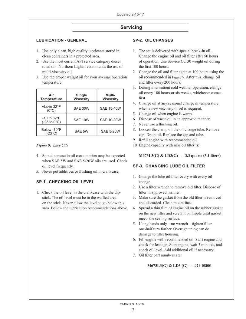
LUBRICATION - GENERAL
1. Useonlyclean,highqualitylubricantsstoredincleancontainersinaprotectedarea.
2. UsethemostcurrentAPIservicecategorydieselratedoil.NorthernLightsrecommendstheuseofmulti-viscosityoil.
3. Usetheproperweightoilforyouraverageoperationtemperature.
Figure 9: Lube Oils
4. SomeincreaseinoilconsumptionmaybeexpectedwhenSAE5WandSAE5-20Woilsareused.Checkoillevelfrequently.
5. Neverputadditivesorflushingoilincrankcase.
SP-1. CHECKING OIL LEVEL
1. Checktheoillevelinthecrankcasewiththedip-stick.Theoillevelmustbeinthewaffledarea
onthestick.Neverallowtheleveltogobelowthisarea.Followthelubricationrecommendationsabove.
SP-2. OIL CHANGES
1. Thesetisdeliveredwithspecialbreak-inoil. Changetheengineoilandoilfilterafter50hours ofoperation.UseServiceCC30weightoilduring
thefirst100hours.2. Changetheoilandfilteragainat100hoursusingthe
oilrecommendedinFigure9.Afterthis,changeoilandfilterevery200hours.
3. Duringintermittentcoldweatheroperation,changeoilevery100hoursorsixweeks,whichevercomesfirst.
4. Changeoilatanyseasonalchangeintemperaturewhenanewviscosityofoilisrequired.
5. Changeoilwhenengineiswarm.6. Disposeofwasteoilinanapprovedmanner.7. Neveruseaflushingoil.8. Loosentheclampontheoilchangetube.Remove
cap.Drainoil.Replacethecapandtube.9. Refillenginewithrecommendedoil.10.Enginecapacitywithnewoilfilteris:
M673L3(G) & LD3(G) – 3.3 quarts (3.1 liters) SP-3. CHANGING LUBE OIL FILTER
1. Changethelubeoilfiltereverywitheveryoilchange.
2. Useafilterwrenchtoremoveoldfilter.Disposeoffilterinapprovedmanner.
3. Makesurethegasketfromtheoldfilterisremovedanddiscarded.Cleanmountface.
4. Spreadathinfilmofengineoilontherubbergasketonthenewfilterandscrewitonnippleuntilgasketmeetsthesealingsurface.
5. Usinghandsonly–nowrench–tightenfilter one-halfturnfarther.Overtighteningcando damagetofilterhousing.6. Fillenginewithrecommendedoil.Startengineand
checkforleakage.Stopengine,wait3minutes,andcheckoillevel.Addadditionaloilifnecessary.
7. Oilfilterpartnumbersare:
M673L3(G) & LD3 (G) – #24-08001
Air Single Multi- Temperature Viscosity Viscosity
Above 32°F SAE 30W SAE 15-40W (0°C)
-10 to 32°F SAE 10W SAE 10-30W (-23 to 0°C)
Below -10°F SAE 5W SAE 5-20W (-23°C)
Updated 2-15-17

OM673L3 10/18
18
Servicing
SP-4. AIR CLEANER
1. Inspectaircleanerevery250hours.Industy conditionscheckmoreoften.2. Inspecttheelement.Ifitisdirty,washtheelementin
soapywater.Rinseanddrythoroughlybefore re-installing.Replaceifnecessary.Partnumberis: M673L3 & LD3 - #24-28003
NOTE: Make absolutely sure no impurities enter the engine while changing the element. Do NOT run the engine with the air cleaner removed.
SP-5. V-BELTS
1. CheckthetensionandwearontheV-beltdaily.2. Useyourthumbtopressonthebeltatthemidpoint
betweenthecrankshaftandalternatorpulleys.Thetensioniscorrectifthebeltcanbedepressedabout3/16in.(5mm).
Figure 10: Valve Adjustment
SP-6. VALVE CLEARANCES
1. Adjustvalveclearanceevery1000hours.2. Valveadjustmentsshouldbedoneifthecylinder
headboltshavebeenre-tightened.EngineshouldbecoldandNOTrunning.
3. TobringtheNo.1cylindertotopdeadcenterinthecompressionstroke,alignthetimingmark;thetopmarkofthecrankpulleywiththatofthetiminggearcase.Removetherockerarmcoverandturnthecrankshaftfowardandbackward.IftheinletandexhaustvalvesoftheNo.1cylinderdonotmoveitisintopdeadcenterposition.Whenthevalvesmove,orrock,turnthecrankshaftonefullturnandalignthetopmarkofthecrankpulleywiththetopmarkofthetiminggearcase.
4. Loosenthelocknutandadjusttheclearancebetweentherockerarmandvalveguideofboththeintakeandexhaustvalveswiththeadjustmentscrew(Figure 10).Clearanceonbothintakeandexhaustvalvesshouldbe0.008in.(0.2mm).
5. Repeatsteps3and4foreachcylinder.Eachsetofvalvesmustbeadjustedindividually.
6. Replacetherockerarmcover.Tightencovernutsto5-8ft/lbs(0.8-2.3kg/m).
Figure 11: Timing Mark
Cylinder No. 1 2 3
Valve Arrangement Int. Exh. Int. Exh. Int. Exh.
When No.1 cylinderis at Top Dead Centerin the compressionstroke
With the crankshaftturned 3600 innormal direction fromabove
Valve Arrangement
Updated 6-23-10

OM673L3 10/18
19
Servicing
FUELS - GENERAL
1. Useonlyclean,highqualityfuelsofthefollowingspecifications,asdefinedbyASTMdesignationD975fordieselfuels:
a. UseGradeNo.2dieselatambienttemperatures abovefreezing32°F(0°C). b. UseGradeNo.1atambienttemperaturesbelow freezingandforalltemperaturesatanaltitudeof above5,500ft.(1500meters).2. Usefuelhavinglessthan1%sulphur(preferably
lessthan0.5%).3. Thecetanenumbershouldbeaminimumof45.4. DONOTusetheseunsuitablegradesoffuel: a. Domesticheatingoils,alltypes. b. ClassBengine. c. ClassDdomesticfuels. d. ClassE,F,GorHindustrialormarinefuels. e. ASTM-D975-60TNo.4-Dandhighernumber fuels.5. Storingfuel: a. Keepdirt,scale,water,andotherforeignmatter outoffuel. b. Avoidstoringfuelforlongperiodsoftime. c. Fillthefueltankattheendofeachday’s operation.Thiswillreducecondensation.
SP-7, 8 and 9. FUEL FILTERS
1. Yourgeneratorsetshouldhaveaprimaryfuelfilterinstalled.WerecommendtheRacorbrandoffuelfilter-waterseparators.
a. Checktheprimaryfuelfilterdailyas recommendedbythefiltermanufacturer. Emptythecollectionbowlasnecessary. b. Changetheelementasoftenasnecessaryor every500hours. c. Ifthebowlfillswithwater,changetheprimary andsecondaryelementimmediately.2. Changesecondaryfuelfilterevery500hours. a. Removethespin-onfilterbyturningit counterclockwisewithafilterwrench.Fillthe newcartridgewithfuelandinstallitafter applyingengineoiltogasketsurface.Screwon untilthegasketsurfacecomesintocontactwith sealingsurfaceoffilterbase.Then,tightenit two-thirdsofaturnbyhand.Donotovertighten. b. Fuelfilterpartnumberis:
M673L3(G) & LD3(G) - #24-52020
OM673L3 10/18
20
Servicing
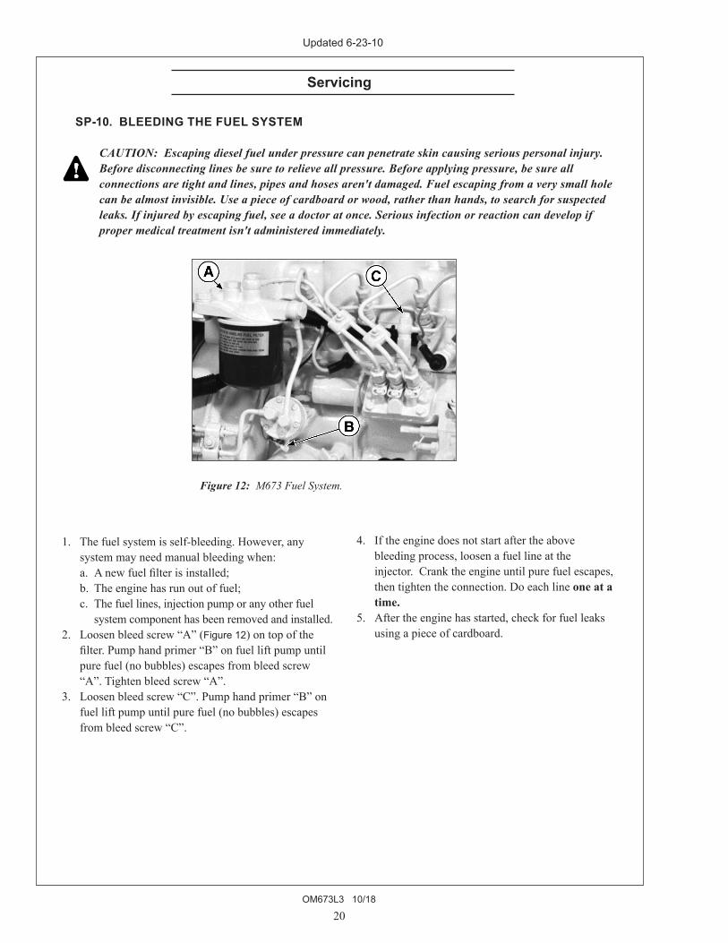
Figure 12: M673 Fuel System.
SP-10. BLEEDING THE FUEL SYSTEM
CAUTION: Escaping diesel fuel under pressure can penetrate skin causing serious personal injury. Before disconnecting lines be sure to relieve all pressure. Before applying pressure, be sure all connections are tight and lines, pipes and hoses aren't damaged. Fuel escaping from a very small hole can be almost invisible. Use a piece of cardboard or wood, rather than hands, to search for suspected leaks. If injured by escaping fuel, see a doctor at once. Serious infection or reaction can develop if proper medical treatment isn't administered immediately.
1. Thefuelsystemisself-bleeding.However,anysystemmayneedmanualbleedingwhen:
a. Anewfuelfilterisinstalled; b. Theenginehasrunoutoffuel; c. Thefuellines,injectionpumporanyotherfuel systemcomponenthasbeenremovedandinstalled.2. Loosenbleedscrew“A”(Figure 12)ontopofthe
filter.Pumphandprimer“B”onfuelliftpumpuntilpurefuel(nobubbles)escapesfrombleedscrew“A”.Tightenbleedscrew“A”.
3. Loosenbleedscrew“C”.Pumphandprimer“B”onfuelliftpumpuntilpurefuel(nobubbles)escapesfrombleedscrew“C”.
4. Iftheenginedoesnotstartaftertheabove bleedingprocess,loosenafuellineatthe
injector.Cranktheengineuntilpurefuelescapes,thentightentheconnection.Doeachlineone at a time.
5. Aftertheenginehasstarted,checkforfuelleaksusingapieceofcardboard.
Updated 6-23-10

OM673L3 10/18
21
Servicing
Updated 11-8-13
COOLING SYSTEM - GENERAL
NOTE: Be sure to close the sea-cock before working on the engine cooling system.
CAUTION: The cooling water in the engine reaches extremely high temperatures. You must use extreme caution when working on hot engines to avoid burns. Allow the engine to cool before work-ing on the cooling system. Open the filler cap care-fully, using protective clothing when the engine is warm.
WATER QUALITY1. Distilled,deionized,softwaterispreferredforusein
coolingsystems.Bottleddistilledwaterfromafoodstoreorwatersupplierisrecommended.Tapwateroftenhasahighmineralcontent.TapwatershouldNEVER beputinacoolingsystemunlessfirsttestedbyawaterqualitylaboratory.DonotusewatermadebythereverseosmosismethodunlessithasbeenPHneutralized.
2.Hereareacceptablewaterqualityspecifications:
3. Ifchlorides,sulfatesortotaldissolvedsolidsarehigherthantheabovegivenspecification,thewatermustbedistilled,demineralized,or
deionizedbeforeitisusedinacoolingsystem.4. Iftotalhardnessishigherthan170ppmandallother
parametersarewithinthegiven specifications,thewatermustbesoftenedbeforeitis
usedtomakecoolantsolution.
SP-11. CHECK THE COOLANT LEVEL
1. Checkthecoolantleveleachdaybeforestartingtheengine.Checkthewaterlevelbyremovingthepres-surecapfromtheexpansiontankorradiator.
Inordertogivethecoolingwateranopportunitytoexpand,thelevelshouldbeabout1in.(2.5cm)belowthefillercapsealingsurfacewhentheengineiscold.
2. Thepressurevalveinthefillercapreleaseswhenthepressureisapproximately7PSI(0.5bar).Useacappressuretestertocheckcapifyoususpectitisfaulty.
SP-12. COOLING SYSTEM FLUSHING
1. Flushthecoolingsystemevery2500hoursorevery12months,whichevercomesfirst.
a.Removeexpansiontankcapanddrainengine block. b.Leavealldrainsopen. c.Pourcleanwaterintoexpansiontankuntil
watercomingfromdrainsisfreeof discolorationandsediment. d.Letwaterdraincompletely. e.Closedrainsandrefillwithrecommended mixture. NOTE: Open sea cock before running engine.
2. CoolantSpecifications: Use50%water/50%ethyleneglycolantifreeze
mix.Antifreezemixtureisrecommendedasagoodyear-roundcoolant,butnotmethylalcoholbasedantifreezebecauseofitslowboilingpoint.Also,antifreezewithhighsilicateshouldnotbeusedasitcouldcausesilicagelationproblems.
3. Checkhosesandconnectionsandrepairanyleakage.
Parts GrainsContaminates per Million per Gallon
Maximum Chlorides 40 2.5
Maximum Sulfates 100 5.9
Maximum Dissolved Solids 340 20.0
Maximum Total Hardness 170 10.0
PH Level 5.5 to 9.0

OM673L3 10/18
22
Servicing
Updated 11-8-13
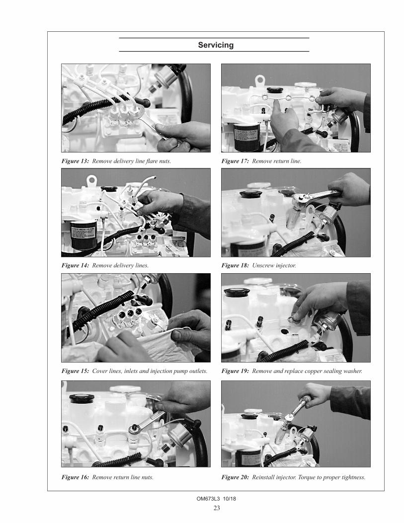
SP-13. INJECTOR SERVICE
1. Injectorsshouldbecheckedevery1000hours,ormoreoftenasnecessary.CheckshouldbemadebyaNorthernLightsdealerorlocalinjectionrepair
station.
CAUTION: Escaping diesel fuel under pressure can have sufficient force to penetrate the skin causing serious personal injury. If injured by escaping diesel fuel, see a doctor at once.
2. Injectorremoval: a. Cleanloosedirtfromaroundtheinjectorsand thefuellines. b. Relievehighpressureinthefuellinesby looseningthedeliverylineflarenutsateach injector(Figure 13). c. Removedeliverylinesbydisconnectingfrom injectorsandinjectionpump(Figure 14).Remove alllinesasanassembly;donotremovethe clamp.Covertheendsofthelines,theinjector inletsandinjectionpumpoutletstokeepdirtout (Figure 15). d. Removethereturnlineretainingbolts(Figure 16). Removethereturnline(Figure 17). e. Unscrewandremovetheinjectors(Figure 18). NOTE: Do not use pry bars to remove injectors from cylinder head. f. Afterremovingtheinjectors,discardthecopper sealingwashersfromtheinjectorholeinthehead (Figure 19).Coverholestopreventdirtanddebris fromenteringthecylinders.
3. Injectorinstallation: a. Installanewcoppersealingwasherineach injectorhole(Figure 19). b. Screwininjectorandtightento43or50ft/lbs (6to7kgm)(Figure 20). NOTE: Overtightening can damage injector. c. Installreturnlineusingnewcoppersealingbelow
eachconnection.Tightenreturnlineretaining boltsto22-30ft/lbs.
d. Installdeliverylines.Leavelooseatinjectorsfor bleeding. e. Cranktheenginetofilllines.Tightenlinesat
injectors.Startengineandcheckforleaksusinga pieceofpaperorcardboard.
DO NOT use hand to check for leaks.
SP-14. INJECTION PUMP
1. Sinceoperatingconditionsmayvaryconsiderably,itisdifficulttogiveadefiniteintervalforcheckingtheinjectionpump.Butasarule,pumpsettings,
maximumspeed,idlespeedandexhaustsmokeshouldbecheckedafterevery2400hoursof
operation.Serviceofthefuelinjectionpumpshouldonlybedoneifchecksindicatepumpmalfunction.
2. Blacksmokecanbeanindicationofpump malfunction.Beforeservicingthepump,checkother
possiblecauses: a. Checkcleanlinessofairfilter. b. Checkvalveclearances. c. Cleanandcheckinjectors.3. Anyrepairwhichinvolvesdisassemblyofthe injectionpumpmustbecarriedoutbyspecially
trainedmechanicswiththepropertoolsandtestequipment.
NOTE: All warranties on the engine become null and void if the injection pump seals are broken by unauthorized persons.
OM673L3 10/18
23
Servicing
Figure 13: Remove delivery line flare nuts.
Figure 14: Remove delivery lines.
Figure 15: Cover lines, inlets and injection pump outlets.
Figure 16: Remove return line nuts.
Figure 18: Unscrew injector.
Figure 19: Remove and replace copper sealing washer.
Figure 20: Reinstall injector. Torque to proper tightness.
Figure 17: Remove return line.

OM673L3 10/18
24
Servicing
SP-15. HEAT EXCHANGER
1. Cleantheheatexchangercoreonceayearorafter2500hoursofoperation.
2. Drainexpansiontankandheatexchanger.3. Removeheatexchangerendcoversandremove
core.4. Cleantheinsideofexchangercoretubesusing ametalrod.Flush,inspectandcleanagainif necessary.5. Reassemble.Fillthecoolingsystem,starttheengine
andcheckforleaks.
SP-16. RAW WATER PUMP
1. Changetheseawaterpumpimpellerevery1000hours,orasneeded.
2. Removethepumpendcover.Pryouttheimpellerusingneedle-nosepliersortwoscrewdrivers.
Besureyouremoveallpiecesoffailedimpeller. NOTE: Place some kind of protection under the
screwdrivers in order not to damage the pump housing.
3. Cleantheinsideofthehousing.4. Pressinthenewimpellerandplacethesealing
washersintheouterendoftheimpellercenterifthishasnotalreadybeendone.
5. Replacethecoverusinganewgasketoro-ring. NOTE: Make sure that there is always an extra
impeller and cover gasket in reserve on board.
GENERATOR ENDS
Themaintenanceandoperationrecommendationsforthegeneratorendarelocatedonpages26-29undertheheading“ACGenerator”.
ELECTRICAL SYSTEM - GENERAL
1. Neverswitchbatteryswitchofforbreakthecircuitbetweenthealternatorandbatterieswhiletheengineisrunning.Regulatordamagecanresult.
2. DoNOTreversethepolarityofbatterycableswheninstallingthebattery.
3. Whenweldingontheunit,disconnecttheACandDCvoltageregulatorandbattery.Isolatetheleads.
4. DisconnectthebatterycableswhenservicingtheD.C.alternator.
5. Nevertestwithascrewdriver,etc.,againstany terminaltoseeifitemitssparks.6. Donotpolarizethealternatororregulator.7. AD.C.circuitbreakerprotectsyourcontrolpanel
andwiringharness.Itislocatedinthesideofthegeneratorjunctionbox.
GLOW PLUGS
1. Eachcylinderissuppliedwithaglowplugwhichservestoheatthecombustionchamberforstarting.
2. Tochecktheglowplugs,loosenthecurrent carryingflatwirebetweentheplus-polesofthe glowplugs(Figure 21).ConnectaD.C.testbulb
betweentheplus-poleofthebatteryandthe plus-poleoftheglowplug.Ifthebulblightsup, theglowplugisfunctioningproperly.3. Checkallglowplugsandreplaceanythatarefaulty.
Figure 21: Glow plugs

OM673L3 10/18
25
BOOSTER BATTERIES
CAUTION: Battery gas can explode. Keep all flames and sparks away from batter-ies.
1. Beforechangingorusingboosterbatteries,check batteryelectrolytelevel.Adddistilledwaterifneces-
sary.2. Boosterandmainbatteriesmusthavethesame voltagerating.3. First,connectpositive(+)terminalofboosterbat-
terytopositive(+)terminalofmainbattery.Then,connectnegative(-)terminalofboosterbatterytogroundontheengineblock(see Figure 22).
4. Removeboosterbatteryafterstartingengine.5. Sealedbatteries:Seemanufacturerchargingand
boosterinstructions.
SP-17 and 18. BATTERY CARE
1. Checkelectrolyteleveldaily.Adddistilledwatertomanufacturer’srecommendedlevel.
2. Batteries,cablesandcableterminalsshould becheckedandcleanedevery100hours. Cleancorrosionwithawaterandbakingsoda solution.Flushwithcleanwater.Tightenterminals
andgreasethemtoinhibitcorrosion.3. Checkthebatteryconditionwithahydrometerevery
250hours.
SP-19. WINTERIZING, OUT-OF-SERVICE
Ifthegeneratorsetwillnotbeusedformorethan3monthsthefollowingpreparationsshouldbetakenforlongtermstorage.• Changeengineoilandfilter,usingAPICJorCK-4,
15W-40oil.• Runtheengineuptoatleast140oFfromasmall,
cleansourceoffueldosedwitheither“Stab-il”brandfuelsystemstabilizer(dieselengineformula),orStanadynePerformancefuelsystemconditioner.Ifneitherofthesefueltreatmentsisavailable,youmayalsouseJohnDeerefuelsystemconditioner.
• Completelydrain,flush,andfillthecoolingsystemwithpre-mixed,50/50,conventionalethylene-glycolheavy-dutydieselenginecoolant(withSCAs).
• Loosenalternatordrivebelt.• Completelysealoffintakeandexhaustopenings
withheavyplasticbagsandducttape.• Coverentireengineinlargeplasticbagandtape
closedatbottomofbag-placeseveralmoistureabsorbingdesiccantpacksinsideplasticbagStoreengineinoriginalshippingcrate,ifpossible,orothersuitablestoragecrate.
• Storeengineinsideabuilding(preferablyclimatecontrolled)topreventcorrosion.
ToRemoveGeneratorSetfromLong-TermStorage:1. Takeoffallprotectivecoveringsandunsealallthe
openingsthatwerecoveredup.2. Installbatteriesthatarefullychargedandconnect
theterminals.3. Installthefanandalternatorbeltsiftheyhadbeen
removed.4. Fillthefueltank.5. Performallpre-startchecks.6. Cranktheenginefor20secondswiththestarter,
withoutlettingtheenginestart.Wait2minutesandcranktheengineanadditional20secondstomakesureallbearingsurfacesarewellcoated.
7. Starttheengineandrunatnoloadinalowidleforseveralminutes.Makesuretheengineiswarmedupandcheckgaugesbeforegoingunderload.
8. Checkallgaugesandcheckforleaks.
Figure 22:Battery connections.
Servicing
Updated 10-17-18

OM673L3 10/18
26
GENERAL1. AGeneratorSetincludestheengine,thegenerator,
andthecontrolor“J”box(Figure 23).2. Thegeneratorandthecontrolor“J”boxproduce
theelectricalpower.3. Generatorexcitationisprovidedbyresidual magnetismandelectricaloutputvoltageiscon-
trolledbytheautomaticvoltageregulator(AVR)locatedinthecontrolbox(Figure 25, Item 2).
GENERATOR (Figure 24) 1. StatorCore 2. StatorCoil 3. EndCover 4. Brush 5. BallBearing 6. SlipRing 7. Frame 8. CouplingPlate 9. FieldCoil 10. FieldCore 11. Shaft 12. VentilationCover
CONTROL BOX (Figure 25) 1. VoltageSelectorTerminal 2. AutomaticVoltageRegulator(AVR) 3. 12VoltDCCircuitBreaker 4. ACCircuitBreaker 5. AVRCircuitBreaker 6. OutputTerminalBoard
AC Generator - TF-276D
Figure 23: Composition.
Figure 25: Control Box Components.
Figure 24: Generator Components.
Updated 1-14-15

OM673L3 10/18
27
CONNECTIONS
1. 120VoltOutput: a. 120voltoutputcanbeselectedbyconnecting theterminalsofthecontrolterminalboardto120 (Figure 26).
Figure 26: Control Terminal Board, 120 Volt Output
b. ConnectU1toU2andV1toV2ontheoutput terminalboard(Figure 27).Connect120volt outputleadstoterminalsU1andV2.
Figure 27: Output Terminal Board, 120 Volt Output
2. 240VoltOutput: a. 240voltoutputcanbeselectedbyconnecting theterminalsofthecontrolterminalboardto240 (Figure 28).
Figure 28: Voltage Selector Terminal, 240 Volt Output b. ConnectU2toV1ontheoutputterminalboard (Figure 29).
Figure 29: Output Terminal Board, 240 Volt Output
3. 120/240VoltOutput a. Connectthecontrolterminalboardfor240volts (Figure 30).
.
Figure 30: Control Terminal Board, 120/240 Volt Output
b. ConnectU2andV1ontheoutputboard (Figure 31).ConnectoutputleadstoU1andV2 andneutralleadtoV1(orU2).240voltoutputis availablefromtheleadsconnectedtoU1andV2. The120voltloadshouldbedividedasequallyas possiblebetweentwo120voltcircuits.
Figure 31: Output Terminal Board, 120/240 Volt Output
AC Generator - TF-276D
Updated 1-14-15

OM673L3 10/18
28
AC Generator - TF-276D
OPERATION Inordertoensurealong,trouble-freelife,the generatormustbeoperatedproperlyandthe specifiedmaintenancemustbeperformed.
OPERATING ENVIRONMENT Alwayskeepelectricalequipmentclean.Moisture,
salt,dust,andoilwilldamagethegenerator.Theoperatingenvironmentmustbekeptascleanandmoisturefreeaspossible.
VENTILATION Goodventilationisimportantforpropergenera-
toroperation.Wheninstallingthegeneratorset,besuretheambienttemperaturedoesnotexceed40°C(104°F)duringoperation.
MAINTENANCE Properandeffectivemaintenanceisrequiredto
ensuretrouble-freeoperation.Inadditiontotheaboveitems,thefollowingarerequired:
1. Periodicallycheckallboltsandnutsforpropertorque.Thisisespeciallytrueforcouplingbolts.
2. Besuretokeepthegeneratorareacleananddry. a. Dustandforeignmaterialmayreducetheflowof coolingair,reducingheatdissipationandcausing thegeneratortooverheat. b. Ifelectricallyconductivedebrisaccumulateson thewindings,orifmoistureorsaltwaterare absorbedintothewindings,thewindingsmay shortorground,reducingvoltageoutput. c. Wipingistheonlyeffectivemethodforremoving dustandforeignmaterials.Useaclean,lint-free pieceofcloth.3. Ifthegeneratorhasnotbeenoperatedforan
extendedperiodoftime,checktheinsulation resistanceofeachstatorcoilandtherotor. DisconnecttheAVRfromthegeneratorwhen performingthistest.
4. VoltageAdjustment a. Ifthereissomevoltage,butitdoesnotbuildup toratedvoltage,voltageadjustmentcanbemade usingthe“handtrimmer”intheAVR(Figure 32). b. Thenormalvoltagesettingatnoloadis121volts at62Hertzor242voltsat62Hertz.
Figure 32: Hand Trimmer Location on AVR.
5. Checktheballbearinginthegeneratorend. a. Listenforunusualnoise. b. Abnormaltemperaturerisecanbenotedby discoloration. c. Ifthebearingisfailing,itmustbereplaced. d. Generatorbearingshouldbereplacedbyyour NorthernLightsdealerat10,000hours.6. Checkthebrushes a. Thecarbonbrushesgraduallywearwithuse,so theymustbeinspectedperiodicallyandreplaced asnecessary. b. Ifthebrushesareexcessivelywornastoexpose thepigtail(Figure 33),sparkingwilloccuratthe surfaceoftheslipring,causingsurfacedamage. Therefore,periodicinspectionofthebrushesis important. c. Normally,thebrusheswillhavetobereplaced withanewbrushassemblywithin3,000hours.
Figure 33: Brush Pigtail.
Updated 1-14-15

OM673L3 10/18
29
9. Parts:SeePartsBookforcompletelist a. Bearing Part#22-68305 b. Brushassembly Part#22-6830410.TestSpecifications:SeeWiringDiagram(s) a. ResistanceofJ-K 16.6ohmat20°C(68°F) b. ResistanceofA-B 0.25ohmat20°C(68°F) c. ResistanceofU1-V2 0.56ohmat20°C(68°F) d. Noloadvoltagesetting 242Vor121Vat62Hzwithcoldgenerator
AC Generator - TF-276D
7. ReplacingBrushes a. Shutdownthegenerator.Removefourscrews andendcoverofthegenerator. b. Brushassemblyisblackplasticwithtwowires leadingtoit.Itislocatedatteno’clockandis heldinpositionbytwoscrews(Figure 34). Removethescrewsandunplugleads.
Figure 34: Brush Location.
c. Attachleadstonewbrushassemblyandinstallit withtheplasticearstowardsthefrontofthe generator. NOTE: Be sure to connect wire J to terminal J, and connect wire K to terminal K.8. GeneratorProtection ToprotectthegeneratorandAVRfrom unbalancedloadsandoverloads,two20amp breakersareplacedintheoutputcircuitandone 3ampbreakerisplacedintheAVRsensing circuit(Figure 35).
Figure 35: Breaker Locations.
Updated 1-14-15

OM673L3 10/18
30
Ifyoucannotcorrectproblemswiththeseprocedures,seeyourNorthern Lights dealer.
Troubleshooting
DC ELECTRICAL SYSTEM PROBLEM POSSIBLE CAUSE RECOMMENDATION(S)
Battery Will Not Charge Looseorcorrodedconnections •Cleanandtightenbatteryconnections.
Sulfatedorwornoutbatteries •Checkspecificgravityofeachbattery. •Checkelectrolytelevelofeachbattery.
Looseordefectivealternatorbelt •Adjustbelttension. •Replacebelt.
Starter Inoperative CheckDCcircuitbreaker •Ifthebreakeristripped,resetit.
Looseorcorrodedconnections •Cleanandtightenloosebatteryand harnessplugconnection.
Lowbatteryoutput •Checkspecificgravityofeachbattery. •Checkelectrolytelevelofeachbattery.
Defectiveelectricalsystem •Repairorreplace. groundwire
Starter Cranks Slowly Lowbatteryoutput •Batteryistoosmall. •Batterycablesaretoosmall.
Checkspecificgravity •Replacebatteryifnecessary. ofeachbattery
Checkelectrolytelevel •Iflow,fillcellswithdistilledwater. ofeachbattery
Looseorcorrodedconnections •Cleanandtightenlooseconnections.
Crankcaseoiltooheavy •Fillwithoilofappropriateviscosity.
Entire Electrical System CheckDCcircuitbreaker •Ifbreakeristripped,resetit.Does Not Function Faultyconnection •Cleanandtightenbatteryandharness plugconnections.
Sulfatedorwornoutbatteries •Checkspecificgravityandelectrolyte levelofeachbattery.
DeadBattery •Chargebattery.
Updated 6-22-10

OM673L3 10/18
31
Troubleshooting
ENGINE PROBLEM POSSIBLE CAUSE RECOMMENDATION(S)
Engine Hard to Start Improperstartingprocedure •Seestartingsectionofthismanual.Takeor Will Not Start specialnoteofBypassSwitchoperation.
Nofuel •Checkleveloffuelinfueltank.
Lowbatteryoutput •Checkelectrolytelevelandcondition.
Excessiveresistance •Cleanandtightenallbatteryconnections. instartingcircuit
Crankcaseoiltooheavy •Useoilofproperviscosity.
Impropertypeoffuel •Consultfuelsupplierandusepropertype offuelforoperatingcondition.
Water,dirtorairinfuelsystem •Drain,flush,fillandbleedsystem.
Cloggedprimaryorsecondary •Cleanorreplaceprimaryfilterelement, fuelfilterelement replacesecondaryfilterelement.
Dirtyorfaultyinjectionnozzles •Haveyourdealercheckinjectionnozzles.
Fuelinjectedbutnoignition •Glowplugmalfunction. •Injectiontimingnotcorrect. •Lowcylindercompressionpressure.
Engine Runs Irregularly Belownormalenginetemperature •Removeandcheckthermostat.or Stalls Frequently Cloggedprimaryorsecondary •Cleanorreplaceprimaryfilterelement, fuelfilterelement replacesecondaryfilterelement.
Waterordirtinthefuelsystem •Drain,flush,fillandbleedsystem.
Dirtyorfaultyinjectionnozzles •Haveyourdealercheckinjectionnozzles.
Airinfuelsystem •Inspectclampsandhosesonsuctionside offuelpumpforairleak.
Impropertypeoffuel •Consultfuelsupplierandusepropertype offuelforoperatingcondition.
Lowidle,notstable •Unevencompressioncylinders.
Lack of Engine Power Intakeairrestriction •Serviceaircleaner.
Cloggedprimaryorsecondary •Cleanorreplaceprimaryfilterelement, fuelfilterelement replacesecondaryfilterelement.
Impropertypeoffuel •Consultfuelsupplierandusepropertypeof fuelforoperatingconditions.
Overheatedengine •See“EngineOverheats”innextcategory.
Belownormalenginetemperature •Removeandcheckthermostat.
Impropervalveclearance •Resetvalves.Bestdonebydealer.
Dirtyorfaultyinjectionnozzles •Replaceinjectors.Bestdonebydealer. •Seeyourlocaldealer.

OM673L3 10/18
32
Troubleshooting
ENGINE PROBLEM POSSIBLE CAUSE RECOMMENDATION(S)
Lack of Engine Power Cylindercompressionpressurelow •Adjustvalveclearance.(continued) •Adjustnozzleholderalignment.
Engine Overheats Lowcoolantlevelorcooling •Filltankorradiatortoproperlevel. systemdefective •Checkhosesforlooseconnections andleaks. •Fanbeltslipping.
Keelcoolingtubeshavebeen •Removepaintfromtubes. painted
Coolingsystemneedsflushing •Flushcoolingsystem.
Defectivethermostat •Removeandcheckthermostat.
Defectivetemperaturegauge •Checkwatertemperaturewiththermometer andreplacegaugeifnecessary.
Waterpumpimpellerworn/broken •Checkimpellerandreplaceifnecessary.
Engine Knocks Insufficientoil •Callyourdealer.
Injectionpumpoutoftime •Callyourdealer.
Belownormalenginetemperature •Checkyourthermostats. •Checkwatertemperaturetoseeif temperaturegaugeisworkingproperly.
Engineoverheating •See“EngineOverheating”section.
High Fuel Consumption Impropertypeoffuel •Usecorrectfuelfortemperature.
Cloggedordirtyaircleaner •Serviceaircleaner.
Impropervalveclearance •Seeyourdealer.
Injectionnozzlesdirty •Seeyourdealer.
Injectionpumpoutoftime •Seeyourdealer.
Engineoverloaded •Checkloadusage.
Enginenotatpropertemperature •Checkyourthermostats. •Checkwatertemperaturewiththermometer andreplacegaugeifnecessary.
Below Normal Thermostatsnotworkingproperly •Checkthermostats.Engine Temperature Temperaturegauge •Checkwatertemperaturewiththermometer. notworkingproperly
Ifyoucannotcorrectproblemswiththeseprocedures,seeyourNorthern Lights dealer.
Updated 6-22-10

OM673L3 10/18
33
Troubleshooting
ENGINE PROBLEM POSSIBLE CAUSE RECOMMENDATION(S)
Low Oil Pressure Lowoillevel •Fillcrankcasetoproperlevel.
Cloggedfilterandstraineror •Repairorreplace. wornbearingsandoilpump Impropertypeofoil •Drainandfillcrankcasewithcorrectoil.
Partiallypluggedoilfilter •Replacefilter.
High Oil Consumption Break-inperiod •Oilconsumptiondecreasesafterbreakin.
Crankcaseoiltoolight •Useproperviscosityoil.
Oilleaks •Checkforleaksinlinesaroundgaskets anddrainplug.
Engine Emits Black Cloggedordirtyaircleaner •Serviceaircleaner.or Gray Exhaust Smoke Defectivemuffler •Havedealercheckbackpressure. (backpressuretoohigh)
Improperfuel •Usecorrectfuelfortemperature.
Injectionnozzlesdirty •Seeyourdealer.
Engineoutoftime •Seeyourdealer.
Engine Emits Improperfuel •Usecorrectfuelfortemperature.White Smoke Coldengine •Warmupenginetonormaloperating temperature.
Defectivethermostat •Removeandcheckthermostat.
Engineoutoftime •Seeyourdealer.
Ifyoucannotcorrectproblemswiththeseprocedures,seeyourNorthern Lights dealer.

OM673L3 10/18
34
Northern Lights Marine Data
Model: M673L3 (G) M673LD3 (G) RPM 1800 1500 1800 1500 kWRating 6.0 5.0 5.0 4.5 Frequency(Hz) 60 50 60 50
GENERAL INFORMATION Cylinders 3 3 3 3
Displacement 46.4 in3 46.4 in3 46.4 in3 46.4 in3 (0.761 ltr) (0.761 ltr) (0.761 ltr) (0.761 ltr)
Cycle 4 4 4 4
Bore 2.64 in 2.64 in 2.64 in 2.64 in (67 mm) (67 mm) (67 mm) (67 mm)
Stroke 2.83 in 2.83 in 2.83 in 2.83 in (72 mm) (72 mm) (72 mm) (72 mm)
Rotation(facingflywheel) CCW CCW CCW CCW
CompressionRatio 23.5:1 23.5:1 23.5:1 23.5:1
CrankcaseCapacityw/OilFilter 3.2 qts 3.2 qts 3.2 qts 3.2 qts (3.0 ltr) (3.0 ltr) (3.0 ltr) (3.0 ltr)
Aspiration Natural Natural Natural Natural
DryWeight/CompleteUnit 362 lbs 362 lbs 362 lbs 362 lbs (164 kg) (164 kg) (164 kg) (164 kg)
Height 20.25 in 20.25 in 20.25 in 20.25 in (514.5 mm) (514.5 mm) (514.5 mm) (514.5 mm)
Width 19.5 in 19.5 in 19.5 in 19.5 in (495 mm) (495 mm) (495 mm) (495 mm) Length 28.5 in 28.5 in 28.5 in 28.5 in (725 mm) (725 mm) (725 mm) (725 mm)
COOLING SYSTEM ApproximateCoolingSystemCapacity .5 gal .5 gal .5 gal .5 gal (2 ltr) (2 ltr) (2 ltr) (2 ltr) MinimumThrough-HullDiameter 0.75 in 0.75 in 0.75 in 0.75 in (19 mm) (19 mm) (19 mm) (19 mm)
RawWaterPumpInletHoseI.D. 0.75 in 0.75 in 0.75 in 0.75 in (19 mm) (19 mm) (19 mm) (19 mm)
MinimumSeawaterDischarge 0.75 in 0.75 in 0.75 in 0.75 in (19 mm) (19 mm) (19 mm) (19 mm) HeatRejectiontoJacketWater 350 BTU/min 250 BTU/min 350 BTU/min 250 BTU/min
FreshWaterPumpCapacity 5.0 gal/min 4.2 gal/min 5.0 gal/min 4.2 gal/min (18.92 ltr/min) (15.77 ltr/min) (18.92 ltr/min) (15.77 ltr/min)
MaximumSeawaterPumpSuctionHead 39 in 39 in 39 in 39 in (1 m) (1 m) (1 m) (1 m) SeawaterPumpCapacity 8.0 gal/min 7.0 gal/min 8.0 gal/min 7.0 gal/min (30 ltr/min) (26 ltr/min) (30 ltr/min) (26 ltr/min)
KeelCoolerTurboTubeLength 4 ft 4 ft 4 ft 4 ft (1.2 m) (1.2 m) (1.2 m) (1.2 m) KeelCoolerHeadDiameter 0.75 in NPT 0.75 in NPT 0.75 in NPT 0.75 in NPT (19.1 mm) (19.1 mm) (19.1 mm) (19.1 mm) KeelCoolerWaterHoseI.D. DischargeandSuction 1.0 in 1.0 in 1.0 in 1.0 in (25 mm) (25 mm) (25 mm) (25 mm)
Updated 4-12-10
OM673L3 10/18
35
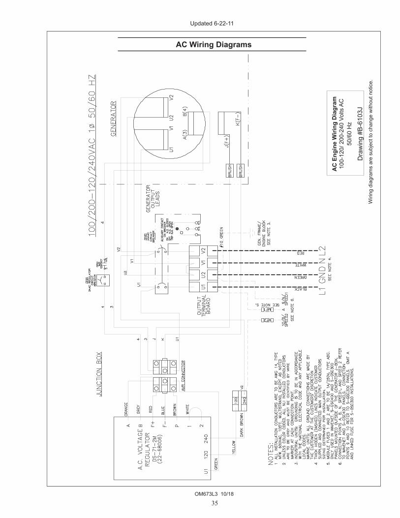
AC Wiring Diagrams
Wiri
ng d
iagr
ams
are
subj
ect t
o ch
ange
with
out n
otic
e.
AC
Eng
ine
Wiri
ng D
iagr
am10
0-12
0/ 2
00-2
40 V
olts
AC
50/6
0 H
z
Dra
win
g #B
-610
3J
Updated 6-22-11

OM673L3 10/18
36
AC Wiring Diagrams
AC
Eng
ine
Wiri
ng D
iagr
am20
0-24
0 Vo
lts A
C
Dra
win
g #B
-610
4F
Updated 6-22-11

OM673L3 10/18
37
AC Wiring Diagrams
AC
Eng
ine
Wiri
ng D
iagr
am12
0 Vo
lts A
C
Dra
win
g #B
-610
5G
Updated 4-9-12

OM673L3 10/18
38
AC Wiring Diagrams
AC
Wiri
ng D
iagr
amTa
iyo T
R276
0 4
Lead
Gen
erat
orw
ith D
ST-6
1-D
FN A
VRD
raw
ing
#B-1
0683
A
Updated 6-6-17

OM673L3 10/18
39
AC Wiring Diagrams
AC
Wiri
ng D
iagr
amM
673L
2 4
Lead
Gen
erat
or
with
DST
-61-
DFN
AVR
Dra
win
g #B
-109
68
Updated 6-6-17

OM673L3 10/18
40
AC Wiring Diagrams
AC
Wiri
ng D
iagr
amTa
iyo
TF27
6D 4
Lea
d G
ener
ator
w
ith D
T_61
-DFN
AVR
Dra
win
g #B
-106
69B
Updated 6-6-17

OM673L3 10/18
41
DC Wiring Diagrams
DC
Wiri
ng D
iagr
amM
/NL
673
12 V
DC
St
anda
rd G
roun
d B+
Con
trol
Dra
win
g #B
-107
50C
Updated 6-6-17

OM673L3 10/18
42
DC Wiring Diagrams
DC
Wiri
ng D
iagr
amM
/ML
673
12 V
DC
Is
olat
ed G
roun
d B+
Con
trol
Dra
win
g #B
-109
66
Updated 6-6-17

OM673L3 10/18
43
DC Wiring Diagrams
DC
Eng
ine
Wiri
ng D
iagr
am12
Vol
ts D
C S
tand
ard
Gro
und
Dra
win
g #B
-987
3
Updated 6-22-11

OM673L3 10/18
44
DC Wiring Diagrams
DC
Eng
ine
Wiri
ng D
iagr
am12
Vol
ts D
C Is
olat
ed G
roun
d
Dra
win
g #B
-824
7A
Updated 6-22-11

OM673L3 10/18
45
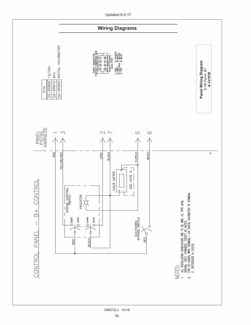
Wiring Diagrams
Pane
l Wiri
ng D
iagr
am S
-1 P
anel
, B+
Deu
tsch
A-1
2798
Updated 6-2-17
OM673L3 10/18
46
Wiring Diagrams
Pane
l Wiri
ng D
iagr
am S
-1B
Pane
l, B+
A
-127
91B
Updated 6-2-17

OM673L3 10/18
47
Wiring Diagrams
Pane
l Wiri
ng D
iagr
am S
-3B
Pane
l, Vi
ewlin
e B+
A-1
2799
A
Updated 6-5-17
OM673L3 10/18
48
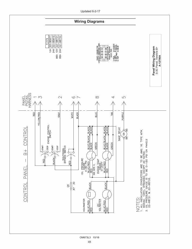
Wiring Diagrams
Pane
l Wiri
ng D
iagr
am S
-3C
Pan
el, V
iew
line
B+
A-1
2790
A
Updated 6-2-17


4420 14th Ave. NW., Seattle WA 98107 Tel: (206) 789-3880 • 1-800-762-0165 • www.northern-lights.comNorthern Lights and Lugger are registered trademarks of Northern Lights, Inc. © 2018 All rights reserved. Litho USA.