Embed Size (px)
Citation preview
1
0101 – 10/95

0
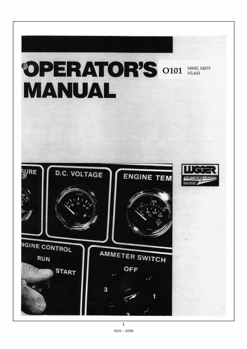
0101 M643,M673
NL643
OPERATOR'S MANUAL Read this operators manual thoroughly before starting to operate your equipment. This manual contains
information you will need to run and service your new unit.
Introduction ................................................................... 2
Unit Identification Models Included ......................................................... 2 Model Numbers .......................................................... 2 Serial Numbers ........................................................... 2
Warranty ....................................................................... 3
Safety Rules ................................................................... 3
Component Locations M643 Marine Generator ............................................. 4 M673 Marine Generator ............................................. 4 NL643 & NL673 Industrial Generators ..................... 5
Panels Northern Lights Generator Sets ............................... 6-7
Operating Procedures Break-in Period .......................................................... 8 Before Starting ........................................................... 8 Starting ....................................................................... 8 Operating .................................................................... 8 Stopping ..................................................................... 8 Shutdowns and Alarms ............................................... 9 Spare Parts .................................................................. 9
Servicing Schedule Chart ...................................... 10-11
Servicing Lubrication - General ............................................... 12 Oil Changes .............................................................. 12 Changing Oil Filter ................................................... 12 Air Filter ................................................................... 12 V-Belts ................................................................ 12-13 Retightening Cylinder Head Bolts ........................... 13 Valve Clearances ...................................................... 13 Fuels - General ......................................................... 13
Servicing continued… Fuel Filters . ......................................................... 13-14 Bleeding the Fuel System ......................................... 14 Injector Service ................................................... 14-16 Injection Pump ......................................................... 16 Cooling System - General ........................................ 16 Cooling System Flushing . .................................. 16-17 Heat Exchanger (Marine) ......................................... 17 Clean Radiator .......................................................... 17 Raw Water Pump (Marine) . .................................... 17 Generator Ends ......................................................... 17 Electrical System - General ...................................... 17 Glow Plugs .......................................................... 17-18 Booster Batteries ...................................................... 18 Battery Care .............................................................. 18 Winterizing - Out-of-Service ................................... 18
AC Generator - TFIII General ..................................................................... 19 Connections . ....................................................... 20-21 Operation .................................................................. 21 Maintenance ........................................................ 21-23
Troubleshooting Electrical ................................................................... 24 Troubleshooting - Engine .................................... 24-25
Data Sheets Marine ...................................................................... 26 Industrial .................................................................. 27
Wiring Diagrams DC Electrical ............................................................ 28 AC Electrical ............................................................ 29
TABLE OF CONTENTS

1
Servicing of marine engines and generator sets presents unique problems. In many cases boats cannot be moved to a repair facility. Marine engines cannot be compared to the servicing of automobiles, trucks or even farm equipment. Failures often occur in remote areas far from competent assistance. Marine engines are taxed far more severely than auto or truck engines; therefore, maintenance schedules
must be adhered to more strictly. Failures begin with minor problems that are overlooked and become amplified when not corrected during routine maintenance. As operator, it is your obligation to learn about your equipment and its proper maintenance. This is not a comprehensive technical service manual. Nor will it make the reader into an expert mechanic. Its aim is to aid you in maintaining your unit properly.
MODELS INCLUDED This manual covers operating instructions for: M643 and M673 marine generator sets, and NL643 industrial generator set.
MODEL NUMBERS Model numbers give unit's application, block model, aspiration and RPM: M-NL 643,673
SERIAL NUMBERS Your set has three serial numbers: an engine number stamped on the block, a generator plate and a generator set plate. Use the
serial number on the generator set plate when ordering parts or in correspondence. The generator set plate is found on the service side of the generator and resembles the drawing below.
INTRODUCTION
UNIT IDENTIFICATION
M - Northern Lights marine generator set
NL - Northern Lights industrial generator set
Model number of engine block Bore Cylinders 64mm 3
67mm 3
M 643
M 673 NL 643Northern Lights industrial diesel generator set with a 643 engine, TFlli-18B generator end, AVR and a radiator.
Northern Lights marine diesel generator set with a 643 engine, TFIli-18B generator end and AVR.
Northern Lights marine diesel generator set with a 673 engine, TFIli-18C generator end and AVR.
2
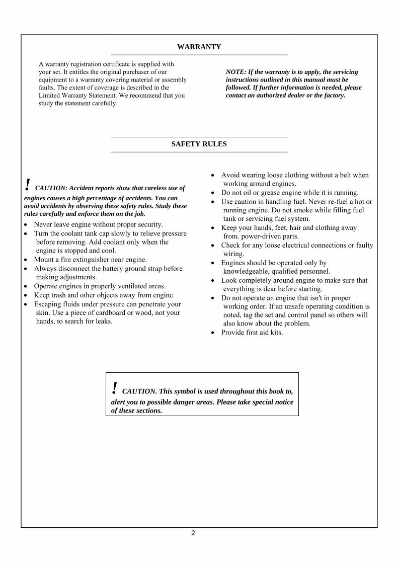
A warranty registration certificate is supplied with your set. It entitles the original purchaser of our equipment to a warranty covering material or assembly faults. The extent of coverage is described in the Limited Warranty Statement. We recommend that you study the statement carefully.
NOTE: If the warranty is to apply, the servicing instructions outlined in this manual must be followed. If further information is needed, please contact an authorized dealer or the factory.
! CAUTION: Accident reports show that careless use of engines causes a high percentage of accidents. You can avoid accidents by observing these safety rules. Study these rules carefully and enforce them on the job. • Never leave engine without proper security. • Turn the coolant tank cap slowly to relieve pressure
before removing. Add coolant only when the engine is stopped and cool.
• Mount a fire extinguisher near engine. • Always disconnect the battery ground strap before
making adjustments. • Operate engines in properly ventilated areas. • Keep trash and other objects away from engine. • Escaping fluids under pressure can penetrate your
skin. Use a piece of cardboard or wood, not your hands, to search for leaks.
• Avoid wearing loose clothing without a belt when working around engines.
• Do not oil or grease engine while it is running. • Use caution in handling fuel. Never re-fuel a hot or
running engine. Do not smoke while filling fuel tank or servicing fuel system.
• Keep your hands, feet, hair and clothing away from. power-driven parts.
• Check for any loose electrical connections or faulty wiring.
• Engines should be operated only by knowledgeable, qualified personnel.
• Look completely around engine to make sure that everything is dear before starting.
• Do not operate an engine that isn't in proper working order. If an unsafe operating condition is noted, tag the set and control panel so others will also know about the problem.
• Provide first aid kits.
WARRANTY
SAFETY RULES
! CAUTION. This symbol is used throughout this book to, alert you to possible danger areas. Please take special notice of these sections.
3
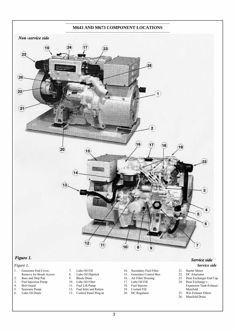
Figure 1. Service side 1 . Generator End Cover,
Remove for Brush Access 2. Base and Drip Pan 3. Fuel Injection Pump 4. Belt Guard 5. Seawater Pump 6. Lube Oil Drain
7. Lube Oil Fill 8. Lube Oil Dipstick 9. Block Drain 10. Lube Oil Filter 11. Fuel Lift Pump 12. Fuel Inlet and Return 13. Control Panel Plug-in
14. Secondary Fuel Filter 15. Generator Control Box 16. Air Filter Housing 17. Lube Oil Fill 18. Fuel Injector 19. Coolant Fill 20. DC Regulator
21. Starter Motor 22. DC Alternator 23. Heat Exchanger End Cap 24. Heat Exchange r-
Expansion Tank-Exhaust Manifold
25. Wet Exhaust Elbow 26. Manifold Drain
M643 AND M673 COMPONENT LOCATIONS

4
NL643 COMPONENT LOCATION
Figure 2
1. DC Alternator 2. Muffler, Exhaust Outlet 3. Starter 4. Power Cable Outlet 5. DC Regulator
6. Bleed Screw 7. Fuel Injection Pump 8. Block Water Drain 9. Lube Oil Drain 10. Lube 0il Dipstick
11. Lube Oil Filter 12. Fuel Lift Pump 13. Fuel Inlet and Return 14. Secondary Fuel Filter 15. Generator Control Box
16. Air Filter 17. Lube Oil Fill 18. Fuel Injector 19. Coolant Fill

5
SERIES I-B GENERATOR CONTROL PANEL
Figure 3A.
SERIES 3-C GENERATOR CONTROL PANEL
Figure 3B.
SERIES 4 GENERATOR CONTROL PANEL
Figure 3C.
1. SHUTDOWN BYPASS-PREHEAT SWITCH. Two functions are built into this switch: The preheating of the engine, and bypassing of the engine safety shutdown circuit. Hold switch in on position 10-20 seconds before starting engine and continue holding on during engine cranking. Release the switch as soon as engine is running. Holding the switch on too long can burn out the heater elements.
2. ENGINE CONTROL SWITCH To start the engine, hold switch in start position until the engine is running. After the engine starts, release switch and it will return to the center position. To stop engine, move switch to stop position and release.
3. HOUR METER: Keeps track of engine running time.
4. OIL PRESSURE GAUGE: The oil pressure gauge shows the oil pressure in the engine lubricating system.
5. ENGINE TEMPERATURE GAUGE: Registers temperature of cooling water.
6. D.C. VOLTMETER: When the engine is stopped, the voltmeter indicates the condition of the battery. When the engine is running, the voltmeter indicates the voltage output of the alternator.
For Series 4 Control Panels Only:
7. A.C. VOLTMETER: Shows the generator output voltage.
8. FREQUENCY METER (HERTZ): The frequency meter indicates alternating current frequency: 60Hz (1800 RPM) or 50Hz (l 500 RPM).
9. AMMETER/VOLTMETER SELECTOR SWITCH: Used to check voltage and current of each phase. Return to "Amps Off” position when not monitoring.
10. A. C. AMMETER Shows the generator load on each phase. The phase is selected with the Ammeter Selector Switch, #9.
CONTROL PANELS
6
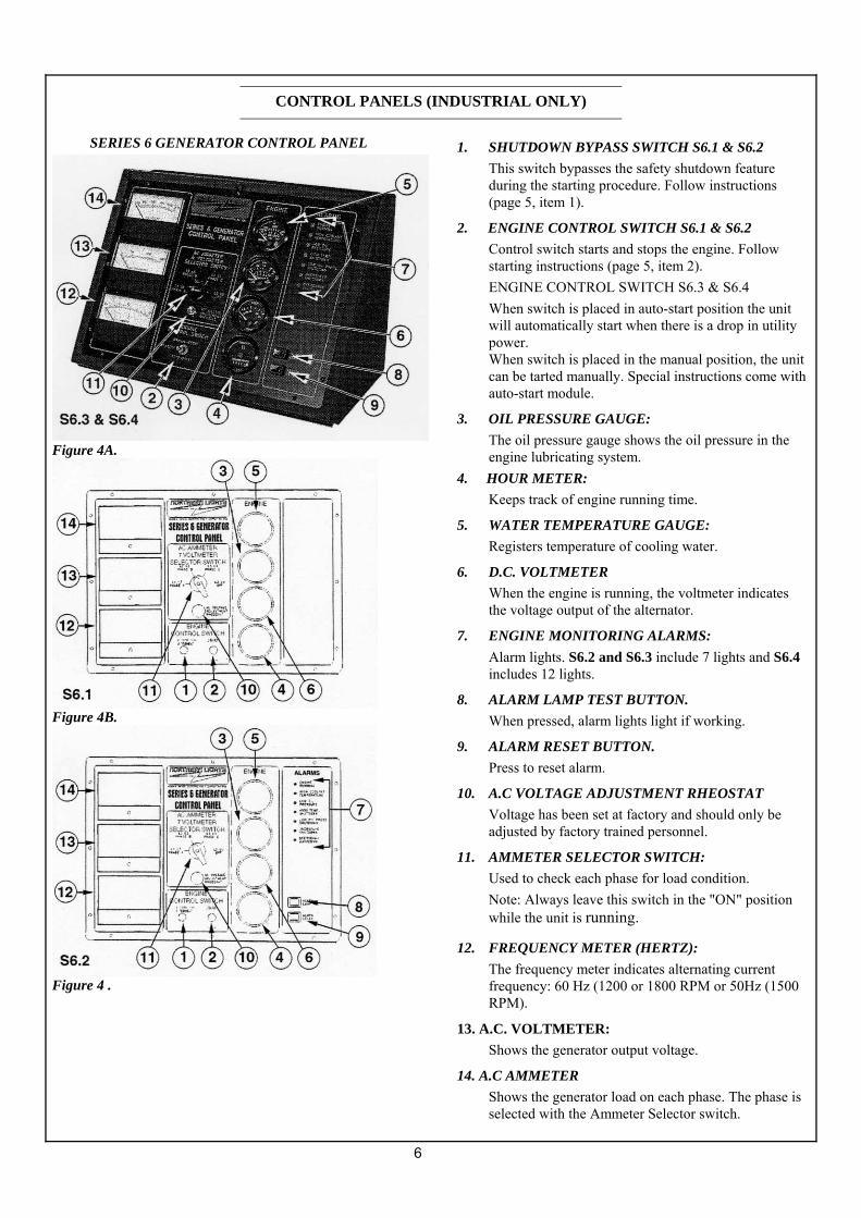
SERIES 6 GENERATOR CONTROL PANEL
Figure 4A.
Figure 4B.
Figure 4 .
1. SHUTDOWN BYPASS SWITCH S6.1 & S6.2 This switch bypasses the safety shutdown feature during the starting procedure. Follow instructions (page 5, item 1).
2. ENGINE CONTROL SWITCH S6.1 & S6.2 Control switch starts and stops the engine. Follow starting instructions (page 5, item 2). ENGINE CONTROL SWITCH S6.3 & S6.4 When switch is placed in auto-start position the unit will automatically start when there is a drop in utility power. When switch is placed in the manual position, the unit can be tarted manually. Special instructions come with auto-start module.
3. OIL PRESSURE GAUGE: The oil pressure gauge shows the oil pressure in the engine lubricating system.
4. HOUR METER: Keeps track of engine running time.
5. WATER TEMPERATURE GAUGE: Registers temperature of cooling water.
6. D.C. VOLTMETER When the engine is running, the voltmeter indicates the voltage output of the alternator.
7. ENGINE MONITORING ALARMS: Alarm lights. S6.2 and S6.3 include 7 lights and S6.4 includes 12 lights.
8. ALARM LAMP TEST BUTTON. When pressed, alarm lights light if working.
9. ALARM RESET BUTTON. Press to reset alarm.
10. A.C VOLTAGE ADJUSTMENT RHEOSTAT Voltage has been set at factory and should only be adjusted by factory trained personnel.
11. AMMETER SELECTOR SWITCH: Used to check each phase for load condition. Note: Always leave this switch in the "ON" position while the unit is running.
12. FREQUENCY METER (HERTZ): The frequency meter indicates alternating current frequency: 60 Hz (1200 or 1800 RPM or 50Hz (1500 RPM).
13. A.C. VOLTMETER: Shows the generator output voltage.
14. A.C AMMETER Shows the generator load on each phase. The phase is selected with the Ammeter Selector switch.
CONTROL PANELS (INDUSTRIAL ONLY)
7
BREAK-IN PERIOD 1 . The first 100 hours on a new or reconditioned engine
are critical to its life and performance. 2. Constantly check the engine temperature and oil
pressure gauges (Sets with Series 3 or 4 panels). 3. Oil consumption is greater during break-in as piston
rings and cylinder liners take time to scat. 4. Break-In 011 Changes: Change engine oil and filter at
50 hours. Chance oil and filter again at 100 hours. (Consult Lubricants Section for oil recommendation.)
5. Retighten head bolts at 50 hours. (See page 13.) Operating Instructions
Generator Sets: Maintain at least a 75% load on your set for the first 100 hours. If this is not possible, maintain no less than a 50% load to ensure proper seating of the piston rings. Vary the load to help seat rings.
BEFORE STARTING 1. Check the water level by removing the pressure cap
from the expansion tank or radiator. In order to give the cooling water an opportunity to expand, the level should be about 1 in. (2.5 cm) below the filler cap sealing surface when the engine is cold.
! CAUTION. Use protective clothing and open the filler cap carefully when the engine is warm to prevent burns. 2. Check the oil level in the crankcase with the dipstick.
The oil level must be in the waffled area on stick. Never allow the level to go below this area. Always add the same viscosity of oil as is already in the crankcase.
3. Check the fuel tank level and open any fuel valves. 4. Marine sets: close the seacock, check and clean the sea
strainer and reopen the seacock. 5. Marine sets: place the battery switch in the ON
position. NOTE: The battery switch must always be kept ON while the engine is running. If the switch is turned OFF while the engine is running, the battery charging regulator could be ruined.
STARTING 1 . Hold Shutdown Bypass-Preheat Switch in ON position
for 10 to 20 seconds before starting a cold engine. Holding switch on too long can bum out the glow plugs. This step is not necessary if the engine is already warm.
2. While holding the Shutdown Bypass-Preheat Switch in ON position, push Engine Control Switch to START position.
3. As soon as the engine starts, release both switches. Do not crank starter for more than 20 seconds. If engine fails to start the first time, be sure starter has stopped before reengaging.
WARNING: Excessive cranking of starter on marine sets equipped with water lift muffler can cause engine damage. If engine does not start after three, 20 second cranks, remove impeller from the seawater pump. This will prevent the muffler from filling with water and backfilling the exhaust line and engine. Once engine starts, shut it off immediately and reinstall the impeller. Restart and check the exhaust overboard outlet for gushes of water.
OPERATING 1 . Units with Series 3, 4&6 Control Panels: Check
gauges often. Oil pressure must bc above 15PSI. The D.C. voltmeter should read between 11 and 15 volts at 80°(25°C) ambient temperature. Water temperature gauge must be below 200°F (94°C). Check AC voltage and frequency meters (Series 4&6 Panels). If gauges deviate from normal levels, shut down the set and investigate.
2. Let the unit run unloaded for a three to five minute warm-up period.
3. Add electrical load. STOPPING 1. Remove electrical load from generator set. 2. Run engine for a 3 to 5 minute cool down period. 3. Move engine control switch to the STOP position
momentarily. 4. Marine sets: shut off seacock, fuel valve and battery
switch.
OPERATING PROCEDURES

8
SHUTDOWNS AND ALARMS 1. Your unit is fitted with a system to protect it from high
water temperature or low oil pressure. a. Generator sets have shutdown systems to stop the
engine. They have no warning horns. b. Other alarms and shutdowns are available as
optional equipment. NOTE: Do not rely on your warning or shutdown system
to the exclusion of careful gauge monitoring. Watching
your gauges can prevent damage to the unit and
dangerous power losses. 2. Do the following when your warning or shutdown
system is activated: a. Check the temperature gauge. If above 205°F
(97°C), shut off the engine immediately. b. Use the Trouble Shooting Guide on page 21 to
isolate the cause of the overheat.
! CAUTION. Do not remove the water fill cap of an overheated engine. Escaping high temperature steam can cause severe burns. Allow the engine to cool and then remove the cap slow1y using protective clothing.
d. Make repairs and restart after the temperature gauge registers below 200°F (94°C.)
e. Watch the temperature gauge regularly and turn off the unit if the temperature rises above 205°F
(97°C.) Repeat troubleshooting. 3. If the shutdown is activated and the temperature gauge
shows temperature within normal temperature range: a. Check the engine crankcase oil level. b. If the oil level is low, fill with recommended
lubricating oil and restart. Watch the oil pressure gauge carefully and shut off the engine if it does not show a normal reading (20-60 PSI) after a few seconds of operation.
c. If the oil level is normal, DO NOT restart the engine. Call your dealer for assistance.
SPARE PARTS 1. ADE recommends that you keep the following spare
parts on hand for field service. The parts are available from your local Northern Lights dealer. Some marine models already have "OnBoard-Kits",a handy box that contains the most common parts you will need.
2. All owners should have the following: a. Primary and secondary fuel filter elements b. 011 filters c. Air filter (industrial only) d. Alternator belt e. Thermostat and gaskets f. Seawater pump impeller & gaskets (Marine only) g. Glow plug h. Injector and washer
3. If your set is operating a long distance from a servicing dealer, add the following: a. Complete set of injectors b. Copper washers for injector change c. Complete set of glow plugs d. Fuel lift pump
OPERATING PROCEDURES

9
The Servicing Schedule Chan below shows the service schedule required for proper maintenance of your generator set. More detailed coverage of each Service Point (SP) is listed on the page noted in the 'page'
co1umn.
DAILY: SP1 Check oil level in engine SP7 Check primary fuel filter SP13 Check cooling water level
Check sea strainer (marine)
AFTER FIRST 50 HOURS: SP2/3 Change engine oil and filter SP5 Check V-belt tension SP6 Adjust valves SP18 Check electrolyte in batteries
Re-tighten head bolts (sec pg. 12)
EVERY 50 HOURS: SP5 Check V-belt tension SPI8 Check electrolyte in batteries
EVERY 100 HOURS. SP2/3 Change engine oil and filter SP4 Check air cleaner SP16 Check and clean radiator (industrial only)
EVERY 200 HOURS: SP8 Change primary fuel filter element SP9 Change secondary fuel filter
EVERY 600 HOURS: SP6 Check valve clearances SPI 1 Check injectors SPI4 Check and flush cooling system SP17 Change impeller (marine) SP19 Check state of charge of batteries
EVERY 2400 HOURS: SP12 Check fuel injection pump SP15 Check and clean heat exchanger (marine only)
SERVICE POINT ......PAGE .............................................................................. ............................. OPER
DAILY 50 Hours
100 Hours
200 Hours
600 Hours
2400 Hours
SP1 ENGINE: 8&12 Check oil level
●
SP2 12 Change engine oil 1) 5) ● SP3 12 Change lube oil filters 1) 5) ●
SP4 12 Check air cleaner 1) 4) ●
SP5 112&13 Check V-Belt tension 1 ) ●
SP6 13 Check valve clearances 1) 5) ●
SP7 FUEL SYSTEM: 13 Check primary filter (Racor) 2)
●
SP8 13&14 Change primary filter element (Racor) 2) 3) ●
SP9 14 Change secondary fuel filter 1) 3) ●
SP 10 14 Bleed the fuel system 3)
SP 11 14-16 Check injectors 1) ●
SP 12 16 Check fuel injection pump ●
SP13 COOLING SYSTEM 8&16 Check cooling water level
●
SP 14 16&17 Check and flush cooling system ●
SP 15 17 Check and clean heat exchanger (marine) ●
SP 16 17 Check and clean radiator fins (industrial) ●
SP 17 17 Change impeller in seawater pump (marine) 1) 3) ●
SP 18 ELECTRICAL SYSTEM: 18 Check electrolyte level in batteries 1) 4)
●
SP 19 18 Check condition of batteries with hydrorneter 1) ●
SP 20 OUT OF SERVICE: 18 Winterizing or out-of-service 3)
1) Perform all maintenance once a year even if hour level has not been reached. 2) Consult manufacturer's maintenance schedule, note on chart. 3) Whenever necessary. 4) More often if necessary.
5) After first 50 hours. 6) Adjust at first 100 hours.
SERVICING SCHEDULE CHART
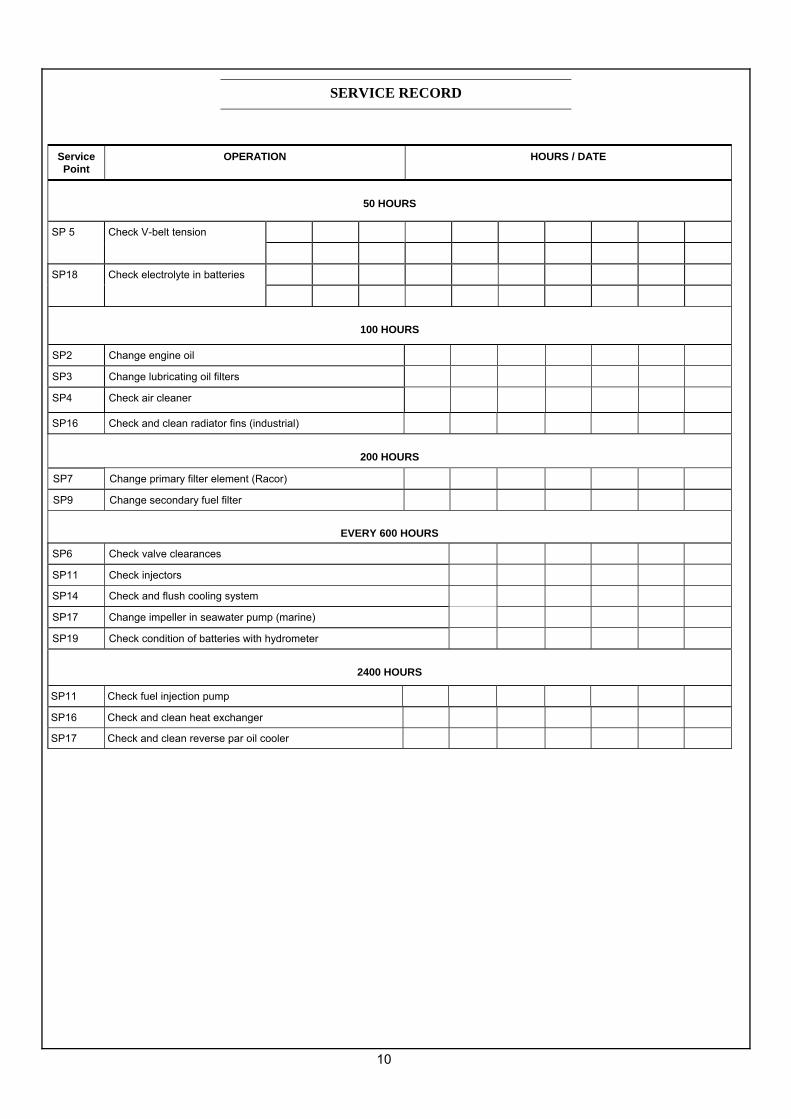
10
Service Point
OPERATION HOURS / DATE
50 HOURS
SP 5 Check V-belt tension
SP18 Check electrolyte in batteries
100 HOURS
SP2 Change engine oil
SP3 Change lubricating oil filters
SP4 Check air cleaner
SP16 Check and clean radiator fins (industrial)
200 HOURS
SP7 Change primary filter element (Racor)
SP9 Change secondary fuel filter
EVERY 600 HOURS
SP6 Check valve clearances
SP11 Check injectors
SP14 Check and flush cooling system
SP17 Change impeller in seawater pump (marine)
SP19 Check condition of batteries with hydrometer
2400 HOURS
SP11 Check fuel injection pump
SP16 Check and clean heat exchanger
SP17 Check and clean reverse par oil cooler
SERVICE RECORD
11
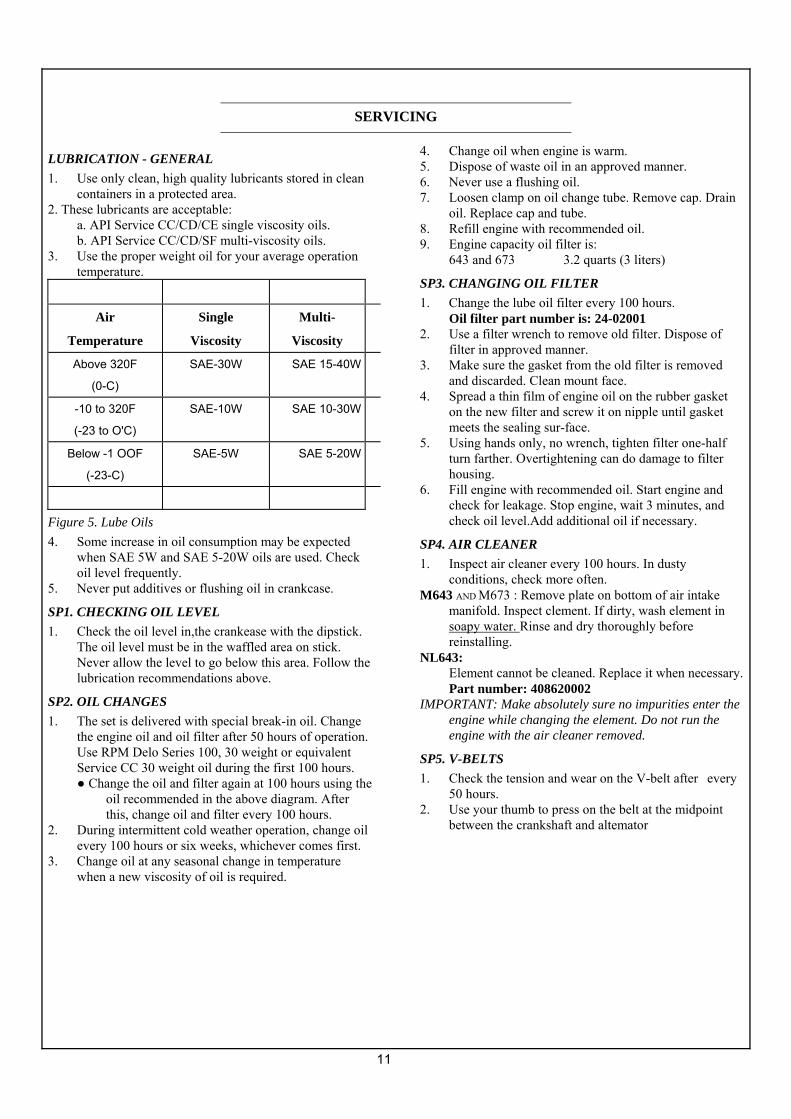
LUBRICATION - GENERAL 1. Use only clean, high quality lubricants stored in clean
containers in a protected area. 2. These lubricants are acceptable:
a. API Service CC/CD/CE single viscosity oils. b. API Service CC/CD/SF multi-viscosity oils.
3. Use the proper weight oil for your average operation temperature.
Air
Temperature
Single
Viscosity
Multi-
Viscosity
Above 320F
(0-C)
SAE-30W SAE 15-40W
-10 to 320F
(-23 to O'C)
SAE-10W SAE 10-30W
Below -1 OOF
(-23-C)
SAE-5W SAE 5-20W
Figure 5. Lube Oils 4. Some increase in oil consumption may be expected
when SAE 5W and SAE 5-20W oils are used. Check oil level frequently.
5. Never put additives or flushing oil in crankcase.
SP1. CHECKING OIL LEVEL 1. Check the oil level in,the crankease with the dipstick.
The oil level must be in the waffled area on stick. Never allow the level to go below this area. Follow the lubrication recommendations above.
SP2. OIL CHANGES 1. The set is delivered with special break-in oil. Change
the engine oil and oil filter after 50 hours of operation. Use RPM Delo Series 100, 30 weight or equivalent Service CC 30 weight oil during the first 100 hours. ● Change the oil and filter again at 100 hours using the
oil recommended in the above diagram. After this, change oil and filter every 100 hours.
2. During intermittent cold weather operation, change oil every 100 hours or six weeks, whichever comes first.
3. Change oil at any seasonal change in temperature when a new viscosity of oil is required.
4. Change oil when engine is warm. 5. Dispose of waste oil in an approved manner. 6. Never use a flushing oil. 7. Loosen clamp on oil change tube. Remove cap. Drain
oil. Replace cap and tube. 8. Refill engine with recommended oil. 9. Engine capacity oil filter is:
643 and 673 3.2 quarts (3 liters)
SP3. CHANGING OIL FILTER 1. Change the lube oil filter every 100 hours.
Oil filter part number is: 24-02001 2. Use a filter wrench to remove old filter. Dispose of
filter in approved manner. 3. Make sure the gasket from the old filter is removed
and discarded. Clean mount face. 4. Spread a thin film of engine oil on the rubber gasket
on the new filter and screw it on nipple until gasket meets the sealing sur-face.
5. Using hands only, no wrench, tighten filter one-half turn farther. Overtightening can do damage to filter housing.
6. Fill engine with recommended oil. Start engine and check for leakage. Stop engine, wait 3 minutes, and check oil level.Add additional oil if necessary.
SP4. AIR CLEANER 1. Inspect air cleaner every 100 hours. In dusty
conditions, check more often. M643 AND M673 : Remove plate on bottom of air intake
manifold. Inspect clement. If dirty, wash element in soapy water. Rinse and dry thoroughly before reinstalling.
NL643: Element cannot be cleaned. Replace it when necessary. Part number: 408620002
IMPORTANT: Make absolutely sure no impurities enter the engine while changing the element. Do not run the engine with the air cleaner removed.
SP5. V-BELTS 1. Check the tension and wear on the V-belt after every
50 hours. 2. Use your thumb to press on the belt at the midpoint
between the crankshaft and altemator
SERVICING
12
pulleys. The tension is correct if the belt can be
depressed about 3/16 in. (5rrim.)
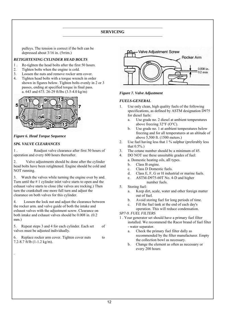
RETIGHTENING CYLINDER HEAD BOLTS 1 . Re-tighten the head bolts after the first 50 hours. 2. Tighten bolts when the engine is cold. 3. Loosen the nuts and remove rocker arm cover. 4. Tighten head bolts with a torque wrench in order
shown in figures below. Tighten bolts evenly in 2 or 3 passes, ending at specified torque in final pass. a. 643 and 673. 26-29 ft/Ibs (3.5-4.0 kg/m)
Figure 6. Head Torque Sequence
SP6. VALVE CLEARANCES
1 . Readjust valve clearance after first 50 hours of operation and every 600 hours thereafter.
2. Valve adjustments should bc done after the cylinder head bolts have been retightened. Engine should be cold and NOT running.
3. Watch the valves while turning the engine over by and. Turn until the # 1 cylinder inlet valve starts to open and the exhaust valve starts to close (the valves are rocking.) Then turn the crankshaft one more full turn and adjust the clearance on both valves for this cylinder.
4. Loosen the lock nut and adjust the clearance between the rocker arm. and valve guide of both the intake and exhaust valves with the adjustment screw. Clearance on both intake and exhaust valves should be 0.008 in. (0.2 mm.)
5. Repeat steps 3 and 4 for each cylinder. Each set of valves must be adjusted individually.
6. Replace rocker arm cover. Tighten cover nuts to 7.2-8.7 ft/lb (1-1.2 kg/m).
Figure 7. Valve Adjustment
FUELS-GENERAL 1. Use only clean, high quality fuels of the following
specifications, as defined by ASTM designation D975 for diesel fuels: a. Use grade no. 2 diesel at ambient temperatures
above freezing 32°F (O°C). b. Use grade no. 1 at ambient temperatures below
freezing and for all temperatures at an altitude of above 5,500 ft. (1500 meters.)
2. Use fuel having less that 1 % sulphur (preferably less that 0.5%.)
3. The cetane number should bc a minimum of 45. 4. DO NOT use these unsuitable grades of fuel:
a. Domestic heating oils, all types. b. Class B engine. c. Class D Domestic fuels. d. Class E, F, G or H industrial or marine fuels. e. ASTM-D975-60T No. 4-D and higher
number fuels. 5. Storing fuel:
a. Keep dirt, scale, water and other foreign matter out of fuel.
b. Avoid storing fuel for long periods of time. c. Fill the fuel tank at the end of each day's
operation. This will reduce condensation. SP7-9. FUEL FILTERS 1 . Your generator set should have a primary fuel filter
installed. We recommend the Racor brand of fuel filter - water separator. a. Check the primary fuel filter dally as
recommended by the filter manufacturer. Empty the collection bowl as necessary.
b. Change the element as often as necessary or every 200 hours
.
SERVICING

13
c. If the bowl fills with water, change the primary and secondary element immediately.
2. Change secondary fuel filter every 200 hours. a. Remove the spin-on filter by turning it
counter-clockwise with a filter wrench. Fill the new cartridge with fuel and install A after applying engine oil to gasket surface. Screw on until the gasket surface comes into contact with sealing surface of filter base. Then, tighten it two-thirds of a turn by hand. Do not overtighten.
3. Fuel filter part number is: M643 and 673 24-52020 NL643 360720020
SP1O. BLEEDING THE FUEL SYSTEM
CAUTION: Escaping diesel fuel under pressure can penetrate skin, causing serious personal injury. Before disonnecting lines, be sure to relieve all pressure. Before applying pressure, be sure all connections are tight and lines, pipes and hoses aren't damaged. Fuel escaping from a very small hole can be almost invisible. Use a piece of cardboard or wood, rather than hands, to search for suspected leaks. If injured by escaping fuel, see a doctor at once. Serious infection or reaction can develop if proper medical treatment isn't administered immediately. 1. The fuel system. is self-bleeding. However, any system
may need manual bleeding when: a. A new fuel filter is installed; b. The engine has run out of fuel; c. The fuel lines injection pump or any other fuel
system component has been removed and installed.
2. Loosen bleed screw "A" (Fig. 8) on top of the filter. Pump hand primer "B" on fuel lift pump until pure fuel (no bubbles) escapes from bleed screw "A." Tighten bleed screw "A".
3. Loosen bleed screw "C". Pump hand primer "B" on fuel lift pump until pure fuel (no bubbles) escapes from bleed screw "A".
4. If the engine does not start after the above bleeding process, loosen a fuel line at the injector. Pump hand primer "B" until pure fuel escapes, then tighten connection. Do each line one-at-a-time.
6. After engine has started, use a piece of cardboard to look
for leaks.
Figure 8. Fuel System
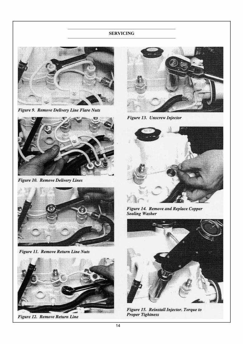
SP11. INJECTOR SERVICE
1. Injectors should be checked every 600 hours. Check should bc made by Northern Lights dealer or local injection repair station.
CAUTION. Escaping diesel fuel under pressure can have sufficient force to penetrate the skin causing serious personal injury. If injured by escaping diesel fuel, see a doctor at once.
2. Injector removal:
a. Clean loose dirt from around the injectors and the fuel lines.
b. Relieve high pressure in the fuel lines by loosening the delivery line flare nuts at each injector (Figure 9.)
c. Remove delivery lines by disconnecting from injectors and injection pump (Figure 10.) Remove all lines as an assembly, do not remove the spacers. Cover the ends of the lines, the injector inlets and injection pump outlets to keep dirt out.
d. Remove the return line retaining bolts (Figure 11.) Remove the retum line (Figure 12.)
e. Unscrew and remove the injectors (Figure 13.) NOTE: Do not use pry bars to remove injectors from cylinder head
.
SERVICING
14
SERVICING
15
f. After removing injectors, discard the copper sealing washers from the injector hole in the head (Figure 14.) Cover holes to prevent dirt and debris from entering cylinders.
4. Injector repair and cleaning: Take injectors to your Northern Lights dealer or local injection repair station for testing and service.
5. Injector installation: a. Install a new copper sealing washer in each
injector hole (Figure 14.) b. Screw in injector and tighten to, 43 or 50 ft/Ibs (6
to 7 Kgm) (Figure 15) . NOTE: Overtightening can damage injector.
c. Install return line using new copper sealing above and below each connection. Tighten return line retaining bolts to 22-30 ft/bs.
d. Install delivery lines. Leave loose at injectors for bleeding.
e. Pump hand level on fuel pump to fill lines. Tighten lines at injectors. Start engine and check for leaks using a piece of paper or cardboard. DO NOT use hand to check for leaks.
SP12.INJECTIONPUMP 1 . Since operating conditions may vary considerably, it is
difficult to give a definite interval. But, as a rule, the pump settings, maximum speed, idle speed and exhaust smoke should be checked after every 2400 hours of operation. Service of the fuel injection pump should only bc done if checks indicate pump malfunction.
2. Black smoke can be an indication of pump malfunctions. Before servicing pump, check the other possible causes. a. Check cleanliness of air filter. b. Check valve clearances. c. Clean and check injectors.
3. Any repair which 1nvolves disassembly of theinjection pump must bc carried out by specially-trained mechanics with the proper tools and test devices.
NOTE: All warranties on the engine become null and void if the injection pump seals are broken by unauthorized persons.
COOLING SYSTEM - GENERAL
NOTE: Marine sets-Be sure to close the seacock before working on the engine cooling system.
! CAUTION: The cooling water in the engine reaches extremely high temperatures. You must use extreme caution when working on hot engines to avoid burns. Allow the engine to cool before working on the cooling system. Open the filler cap carefully, using protective clothing when the engine is warm.
SP13. CHECKING THE COOLANT LEVEL 1. Check the coolant level each day before starting the
engine. 2. Check the coolant level by removing the pressure cap
from the expansion tank or radiator.
! CAUTION: The cooling water in the engine reaches extremely high temperatures. You must use extreme caution when working on hot engines to avoid burns. Allow the engine to cool before working on the cooling system. Open the filler cap carefully, using protective clothing when the engine is warm.
3. In order to give the cooling water an opportunity to, expand, the level should bc about 1 in. (2.5 cm) below the filler cap sealing surface when the engine is cold. 4. The pressure valve in the filler cap releases when the pressure is approximately 7 PSI (0.5 bar.) Use a cap pressure tester to, check cap if you suspect it is faulty.
SP14. COOLING SYSTEM FLUSHING 1. Flush the cooling system every 600 hours or every 12
months, whichever comes first.
MARINE: a. Remove expansion tank cap and open drain cock
on engine block. b. Pour clean water into expansion tank until water
coming from drain is free of discoloration and sediment.
c. Let water drain completely. d. Close drains and refill with recommended
mixture. Note: Open sea cock before running engine
SERVICING
16
INDUSTRIAL: a. Remove radiator cap and open drain cocks on
radiator and engine block. b. Pour clean water into radiator until water coming
from radiator is clear of discoloration. c. Close the radiator drain and continue flushing
until water from engine drain is clear. Open all drain cocks and drain completely. Close drain cock and refill with recommended coolant mixture. Clean fins on radiator.
MARINE AND INDUSTRIAL: 2. Use 50% water/50% ethylene glycol antifreeze mix.
Antifreeze mixture is recommended as a good year-round coolant.
3. Check hoses and connections and repair any leakage.
SP 15. HEA T EXCHANGER (MARINE) 1 . Clean the heat exchanger core once a year or after
2400 hours of operation. 2. Drain expansion tank and heat exchanger. 3. Remove heat exchanger end covers and remove core. 4. Clean the inside of exchanger core tubes using a metal
rod. Flush, inspect and clean again if necessary. 5. Re-assemble. Fill the cooling system, start the engine
and check for leaks.
SPI6. CLEAN RADIATOR (INDUSTRIAL) 1. Remove debris from radiator fins daily. 2. In very dusty applications, clean the radiator with
compressed air or steam cleaner every 100 hours. Clean in the reverse direction of airflow.
SP 17. RAW WATER PUMP (MARINE) 1 . Change the seawater pump impeller every 600 hours,
or as needed. 2. Remove the pump end cover. Pry out the impeller with the help of two screwdrivers. Be sure you remove all pieces of failed impeller.
NOTE: Place some kind of protection under the screwdrivers in order not to damage the housing. 3. Clean the inside of the housing. 4. Press in the new impeller and place the sealing
washers in the outer end of the impeller center if this has not already been done.
5. Replace the cover using a new gasket.
NOTE: Make sure that there is always an extra impeller and cover gasket in reserve on board.
GENERATOR ENDS The maintenance and operation recommendations for
the generator end are in a separate Owner's Manual. If you do not have one of these manuals, contact your local dealer.
ELECTRICAL SYSTEM - GENERAL 1 . Never switch battery switch off or break the circuit
between the alternator and batteries while the engine is running. Regulator damage can result.
2. Do NOT reverse the polarity of battery cables when installing the battery.
3. When welding on the unit, disconnect the regulator and battery. Isolate the leads.
4. Disconnect battery cables when servicing the DC alternator.
5. Never test with a screwdriver, etc., against any terminal to sec if it emits sparks.
6. Do not polarize the alternator or regulator. 7. A DC circuit breaker protects your control panel and
wiring harness. It is located in the side of the generator junction box.
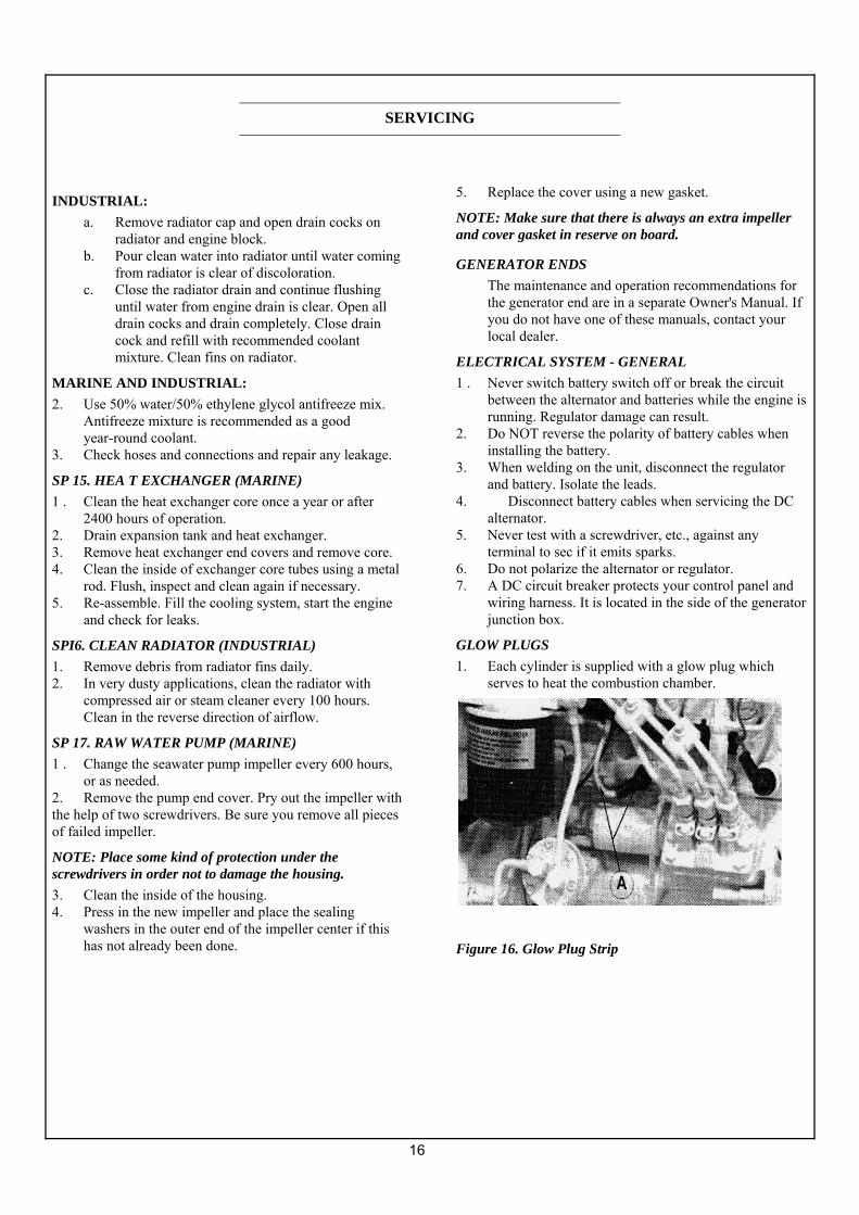
GLOW PLUGS 1. Each cylinder is supplied with a glow plug which
serves to heat the combustion chamber.
Figure 16. Glow Plug Strip
SERVICING

17
2. To check the glow plugs, loosen the current carrying flat wire between the plus-poles of the glow poles (Figure 16.) Connect a DC test bulb between the plus-pole of the battery and the plus-pole of the glow plug. If the bulb lights up, the glow plug is functioning properly.
3. Check all glow plugs and replace any faulty ones.
BOOSTER BATTERIES
! CAUTION. Battery Gas Can Explode. Keep all flames and sparks away from batteries. 2. Before changing or using booster batteries, check
battery electrolyte level. Add distilled water if necessary.
3. Booster and main batteries must have the same voltage rating
4. First, connect positive (+) terminal of booster battery to positive (+) terminal of main battery. Then, connect negative (-) terminal of booster battery to ground on the engine block. (Sec Figure 17.)
5. Remove booster battery after starting engine. 6. Sealed batteries: See manufacturer charging and
booster instructions.
Figure 17. Battery Connections
SP18-19. BATTERY CARE 1. Check electrolyte level every 50 hours or once per
month. Add distilled water to manufacturer's recommended level.
2. Batteries, cables and cable terminals should be checked and cleaned every 100 hours. Clean corrosion with a water and baking soda solution. Flush with clean water. Tighten terminals and grease them to inhibit corrosion.
3. Check the battery condition with a hydrometer every 600 hours.
SP20. WINTERIZING, OUT-OF-SERVICE MARINE: 1. Drain fresh water and seawater cooling systems
completely. Flush fresh water system and refill with proper antifreeze mixture. Remember to shut off seacocks before opening drain cocks.
2. Drain water supply lines and wet exhaust line. 3. Loosen the seawater pump cover and drain pump. INDUSTRIAL: 1. Drain and flush radiator and cooling system. Leave dry
or refill with antifreeze-water mixture. If refilling, start the engine and run to circulate the antifreeze.
2. Fill fuel tank or add biocide as per manufacturer's instructions.
3. Seal air cleaner inlet, exhaust opening, crankcase breather pipe and fuel tank vent with plastic bags and tape.
4. Store the set in a dry, protected place. If unit must be stored outside, be sure it is well protected with a cover.
MARINE AND INDUSTRIAL: 1. Change the crankcase oil and filter. 2. Loosen the alternator belt. 3. Disconnect and clean battery. Remove to warm storage
place if possible. 4. Clean outside of unit. Paint any scratched or chipped
surfaces. Put corrosion preventative on all exposed metal surfaces.
SERVICING
18
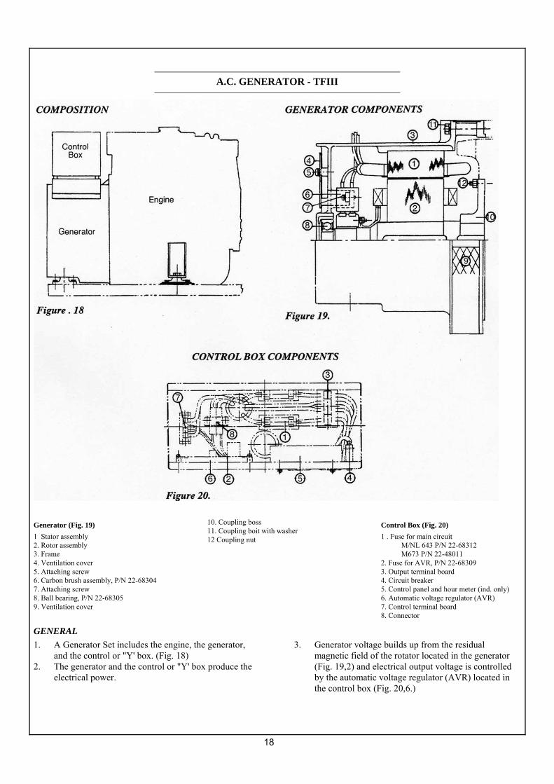
Generator (Fig. 19) 1 Stator assembly 2. Rotor assembly 3. Frame 4. Ventilation cover 5. Attaching screw 6. Carbon brush assembly, P/N 22-68304 7. Attaching screw 8. Ball bearing, P/N 22-68305 9. Ventilation cover
10. Coupling boss 11. Coupling boit with washer 12 Coupling nut
Control Box (Fig. 20) 1 . Fuse for main circuit
M/NL 643 P/N 22-68312 M673 P/N 22-48011
2. Fuse for AVR, P/N 22-68309 3. Output terminal board 4. Circuit breaker 5. Control panel and hour meter (ind. only) 6. Automatic voltage regulator (AVR) 7. Control terminal board 8. Connector
GENERAL 1. A Generator Set includes the engine, the generator,
and the control or "Y' box. (Fig. 18) 2. The generator and the control or "Y' box produce the
electrical power.
3. Generator voltage builds up from the residual magnetic field of the rotator located in the generator (Fig. 19,2) and electrical output voltage is controlled by the automatic voltage regulator (AVR) located in the control box (Fig. 20,6.)
A.C. GENERATOR - TFIII
19
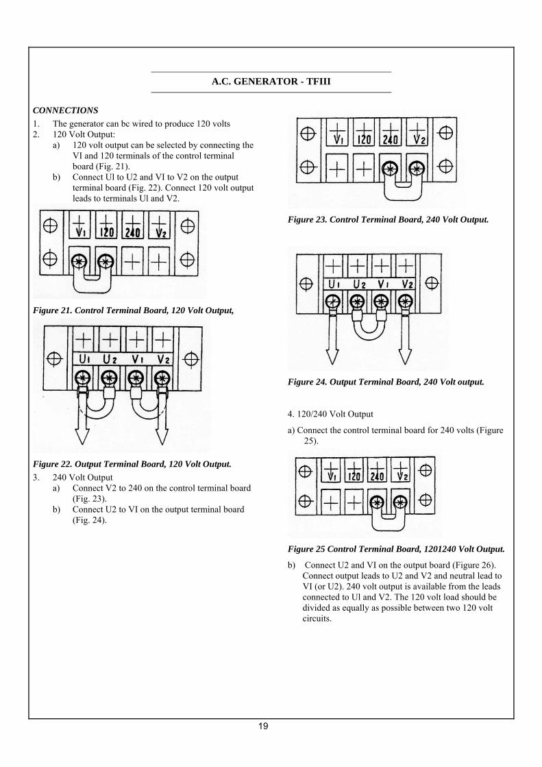
CONNECTIONS 1. The generator can bc wired to produce 120 volts 2. 120 Volt Output:
a) 120 volt output can be selected by connecting the VI and 120 terminals of the control terminal board (Fig. 21).
b) Connect Ul to U2 and VI to V2 on the output terminal board (Fig. 22). Connect 120 volt output leads to terminals Ul and V2.
Figure 21. Control Terminal Board, 120 Volt Output,
Figure 22. Output Terminal Board, 120 Volt Output. 3. 240 Volt Output
a) Connect V2 to 240 on the control terminal board (Fig. 23).
b) Connect U2 to VI on the output terminal board (Fig. 24).
Figure 23. Control Terminal Board, 240 Volt Output.
Figure 24. Output Terminal Board, 240 Volt output.
4. 120/240 Volt Output
a) Connect the control terminal board for 240 volts (Figure 25).
Figure 25 Control Terminal Board, 1201240 Volt Output.
b) Connect U2 and VI on the output board (Figure 26). Connect output leads to U2 and V2 and neutral lead to VI (or U2). 240 volt output is available from the leads connected to Ul and V2. The 120 volt load should be divided as equally as possible between two 120 volt circuits.
A.C. GENERATOR - TFIII

20
Figure 26. Output Terminal Board, 1201240 Volt Output.
OPERA TION In order to ensure long trouble-free life, the generator
must be operated properly and the specified maintenance must be performed.
OPERA TING ENVIRONMENT Always keep electrical equipment clean. Moisture,
salt, dust and oil will damage the generator. The operating environment must bc kept as clean and moisture free as possible.
VENTILATION Good ventilation is important for proper generation
operating. When installing the generator set, bc sure the ambient temperature does not exceed 40°C(104°F) during operation.
MAINTENANCE Proper and effective maintenance is required to ensure
trouble-free operation. In addition to the above items, the following are required.
1. Periodically check all bolts and nuts for proper torque. This is especially true for coupling bolts.
2. Be sure to keep the generator area clean and dry. a. Dust and foreign material may reduce the flow of
cooling air, reducing heat dissipation and causing the generator to overheat.
b. If electrically conductive debris accumulates on the windings, or if moisture or salt water are absorbed into the windings, the windings may short or ground, reducing voltage output.
c. Wiping is the only effective method for removing dust and foreign materials. Use a clean lint free piece of cloth.
3. If the generator has not been operated for an extended period of time, check the insulation resistance of each stator coil and the rotor. Disconnect the AVR from the generator when performing this test (Figure 28).
Figure 28. A VR Connector 4. Voltage Adjustment
a. If there is some voltage but it does not build up to rated voltage, voltage adjustment can be made using the "hand trimmer" in the AVR (Figure 29).
b. The normal voltage setting at no load is 121 volts at 62 Hertz or 242 volts at 62 Hertz.
Figure 29. Hand Trimmer Location
5. Flashing the Fields a. If there is no voltage
buildup on startup (zero volts measured with a voltmeter), the generator may have no residual magnetic field.
A.C. GENERATOR - TFIII

21
b. To flash the field and build the residual magnetism, apply 12 volts DC to terminals K (-) and J (+) as indicated in (Figure 30)
c. AVR must be disconnected when flashing fields or it could be ruined.
Figure 30. Flashing the Fields
6. Check the ball bearing in the generator end.
a. Listen for unusual noise. b. Abnormal temperature rise can be noted by
discoloration. c. If the bearing is failing it must be replaced. d. Generator bearings should be replaced by your
Northern Lights dealer at 10,000 hours. 7. Check the brushes.
a) The carbon brushes gradually wear with use, so they must be inspected periodically and replaced as necessary.
b) If the brushes are excessively worn as to expose the pigtail (Figure 31), sparking will occur at the surface of the slip ring causing surface damage. Therefore, periodic inspection of the brushes is important.
c. Normally the brushes will have to be replaced with a new brush assembly within 3,000 hours.
Figure 31. Brush Pigtail
8. Replacing brushes.
a. Shut down generator. Remove four screws and end cover of the generator.
b. Brush assembly is white plastic with two wires leading to it. It is located at ten o'clock and is held in position by 2 screws (Figure 32). Remove screws and unplug leads.
Figure 32. Brush Location
c. Attach leads to new brush assembly and install it
with the plastic cars towards the front of the generator.
Note: Be sure to connect wire J to terminal J and connect wire K to terminal K. 9. Replacing Fuses
a. To protect the generator and AVR from unbalanced loads and over loads, two 20 amp fuses are placed in the output circuit and one 3 amp fuse is placed in the AVR sensing circuit.
b. Always replace fuses with the same brand and the same circuit interruption characteristics.
Figure 33. Fuse Locations
A.C. GENERATOR - TFIII
22
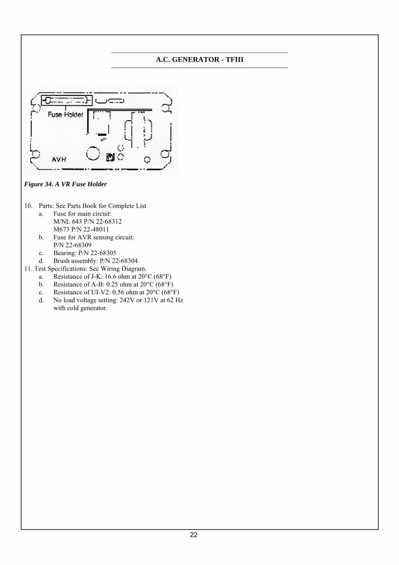
Figure 34. A VR Fuse Holder
10. Parts: See Parts Book for Complete List
a. Fuse for main circuit: M/NL 643 P/N 22-68312 M673 P/N 22-48011 b. Fuse for AVR sensing circuit: P/N 22-68309 c. Bearing: P/N 22-68305 d. Brush assembly: P/N 22-68304
11. Test Specifications: Sec Wiring Diagram. a. Resistance of J-K: 16.6 ohm at 20°C (68°F) b. Resistance of A-B: 0.25 ohm at 20°C (68°F) c. Resistance of UI-V2: 0.56 ohm at 20°C (68°F) d. No load voltage setting: 242V or 121V at 62 Hz
with cold generator.
A.C. GENERATOR - TFIII
23
If you cannot correct problems with these procedures, see your Northern Lights dealer
DC ELECTRICAL SYSTEM
Battery will not charge Loose or corroded connections:
• Clean and tighten battery connections. Sulfated or worn out batteries:
• Check specific gravity of each battery. • Check electrolyte level of each battery.
Loose or defective alternator belt: • Adjust belt tension. • Replace belt.
Starter inoperative Check DC circuit breaker.
• If the breaker is tripped, reset it. Loose or corroded connections:
• Clean and tighten loose battery and harness plug connection.
Low battery output: • Check specific gravity of each battery. • Check electrolyte level of each battery.
Defective electrical system ground wire: • Repair or replace.
Starter cranks slowly Low battery output:
• Batteries too small. • Battery cables too small.
Check specific gravity of each battery. • Replace battery if necessary.
Check electrolyte level of each battery. • If low, fill cells with distilled water.
Crankcase oil too heavy. • Fill with oil of appropriate viscosity.
Loose or corroded connections: • Clean and tighten loose connections.
Entire electrical system does not function Check DC circuit breaker.
• If breaker is tripped, reset it. Faulty connection:
• Clean and tighten battery and harness plug connections.
Sulfated or worn out batteries: • Check specific gravity and electrolyte level of each
battery.
ENGINE
Engine hard to start or will not start Improper starting procedure.
• See starting section of this manual. Take special note of Bypass Switch operation.
No fuel. • Check level of fuel in fuel tank.
Low battery output: • Check electrolyte level and condition.
Excessive resistance in starting circuit: • Clean and tighten all battery connections
Crankcase oil too heavy: • Use oil of proper viscosity.
Improper type of fuel: • Consult fuel supplier and use proper type of fuel for
operating condition. Water, dirt or air in fuel system:
• Drain, flush, fill and bleed system. Clogged primary fuel filter element:
• Clean or replace filter element. Clogged secondary fuel filter element:
• Replace filter element. Dirty or faulty injection nozzles:
• Have your dealer check injection nozzles.
Engine runs irregularly or stalls frequently Below normal engine temperature:
• Remove and check thermostat. Clogged primary fuel filter element:
• Clean or replace filter element. Clogged secondary fuel filter element:
• Replace secondary filter element. Water or dirt in the fuel system.
• Drain, flush, fill and bleed system. Dirty or faulty injection nozzles:
• Have your dealer check injection nozzles. Air in fuel system:
• Inspect clamps and hoses on suction side of fuel pump for air leak.
Improper type of fuel: • Consult fuel supplier and use proper type of fuel for
operating condition.
Lack of engine power Engine overloaded:
• Reduce load. Intake air restriction:
• Service air cleaner. Clogged primary fuel filter element:
• Clean or replace filter element. Clogged secondary fuel filter element:
• Replace filter element. Improper type of fuel:
• Consult fuel supplier and use proper type of fuel for operating, conditions.
Overheated engine: • See "Engine Overheats" in next category
TROUBLESHOOTING

24
If you cannot correct problems with these procedures, see your Northern Lights dealer. Below normal engine temperature:
• Remove and check thermostat. Improper valve clearance:
• Reset valves. Best done by dealer. Dirty or faulty injection nozzles:
• Replace injectors. Best done by dealer. • Sec your local dealer.
Engine overheats Engine overloaded:
• Reduce electrical load. Low coolant level:
• Fill tank or radiator to proper level. • Check hoses for loose connections and leaks.
Keel cooling tubes have been painted (marine.) • Remove paint from tubes.
Cooling system needs flushing. • Flush cooling system.
Defective thermostat: • Remove and check thermostat.
Defective temperature gauge: • Check water temperature with thermometer and
replace gauge if necessary. Water pump impeller worn broken (marine.)
• Check impeller and replace if necessary.
Engine knocks Insufficient oil:
• Call your dealer. Injection pump out of time:
• Call your dealer. Below normal engine temperature:
• Check your thermostats. • Check water temperature to see if temperature
gauge is working properly. Engine overheating:
• See "Engine Overheating" section
High fuel consumption Improper type of fuel.
• Use correct fuel for temperature. Clogged or dirty air cleaner:
• Service air cleaner. Engine overloaded:
• Reduce electrical load. Improper valve clearance:
• See your dealer. Injection nozzles dirty:
• See your dealer. Injection pump out of time:
• See your dealer.
Engine not at proper temperature: • Check your thermostats. • Check water temperature with thermometer and
replace gauge if necessary.
Below normal engine temperature Thermostats not working properly:
• Check thermostats. Temperature gauge not working properly:
• Check water temperature with thermometer.
Low oil pressure Low oil level.
• Fill crankcase to proper level. Improper type of oil:
• Drain and fill crankcase with correct oil. Partially plugged oil filter:
• Replace filter.
High oil consumption Break-in period,
• Oil consumption decreases after break in. Crankcase oil too light:
• Use proper viscosity oil. Oil leaks:
• Check for leaks in lines around gaskets and drain plug.
Engine overheats: • See "Engine Overheats".
Engine emits black or gray exhaust smoke Clogged or dirty air cleaner:
• Service air cleaner. Defective muffler (back pressure too high).
• Have dealer check back pressure. Improper fuel.
• Use correct fuel for temperature. Engine overloaded:
• Reduce electrical load. Injection nozzles dirty:
• See your dealer. Engine out of time:
• Sec your dealer.
Engine emits white smoke Improper fuel.
• Use correct fuel for temperature. Cold engine:
• Warm up engine to normal operating temperature. Defective thermostat:
• Remove and check thermostat. Engine out of time:
• See your dealer.
TROUBLESHOOTING
25
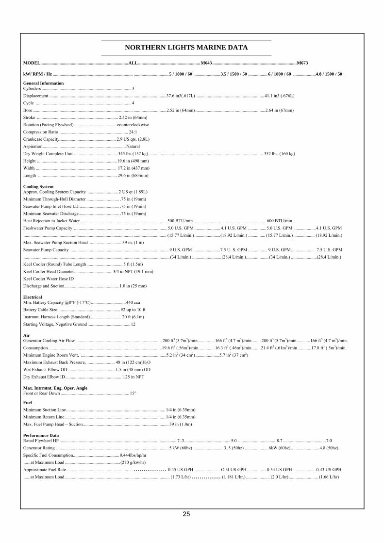
MODEL..............................................................................ALL....................................................... M643...........................................................................M673
kW/ RPM / Hz ....................................................................... ............................... 5 / 1800 / 60 .......................3.5 / 1500 / 50 ................. 6 / 1800 / 60 ....................4.8 / 1500 / 50
General Information Cylinders ................................................................................3 Displacement .......................................................................... .............................37.6 in3(.617L) ................................. .......................... 41.1 in3 (.676L) Cycle .....................................................................................4 Bore ......................................................................................... .............................2.52 in (64mm) .................................. ...........................2.64 in (67mm) Stroke ........................................................................ 2.52 in (64mm) Rotation (Facing Flywheel) ......................................counterclockwise Compression Ratio.............................................................. 24:1 Crankcase Capacity.................................................. 2.9 US qts. (2.8L) Aspiration..........................................................................Natural Dry Weight Complete Unit .......................................345 lbs (157 kg)............................ ............................................... ......................... 352 lbs. (160 kg) Height .......................................................................19.6 in (498 mm) Width ....................................................................... 17.2 in (437 mm) Length ...................................................................... 29.6 in (683nim)
Cooling System Approx. Cooling System Capacity ........................... 2 US qt (1.89L) Minimum Through-Hull Diameter ............................. .75 in (19mm) Seawater Pump Inlet Hose I.D.................................... .75 in (19min) Minimum Seawater Discharge.................................... .75 in (19mm) Heat Rejection to Jacket Water............................................... ..............................500 BTU/min. ................................... ............................ 600 BTU/min Freshwater Pump Capacity .................................................... ..............................5.0 U.S. GPM ....................... 4.1 U.S. GPM ................5.0 U.S. GPM ...................4.1 U.S. GPM ...... .......................................................................................... ............................. (15.77 L/min.) .......................(18.92 L/min.) ............... (15.77 L/min.) .................. (18.92 L/min.) Max. Seawater Pump Suction Head ............................ 39 in. (1 m) Seawater Pump Capacity ....................................................... ............................... 9 U.S. GPM ........................7.5 U. S. GPM ................. 9 U.S. GPM..................... 7.5 U.S. GPM ...... .......................................................................................... ................................ (34 L/min.) ..........................(28.4 L/min.).................... (34 L/min.) .......................(28.4 L/min.) Keel Cooler (Round) Tube Length................................ 5 ft (1.5m) Keel Cooler Head Diameter.................................. 3/4 in NPT (19.1 mm) Keel Cooler Water Hose ID Discharge and Suction ................................................1.0 in (25 mm)
Electrical Min. Battery Capacity @0°F (-17°C)...............................440 cca Battery Cable Size........................................................ #2 up to 10 ft Instrmnt. Harness Length (Standard)............................ 20 ft (6.1m) Starting Voltage, Negative Ground ......................................12
Air Generator Cooling Air Flow................................................... ......................... 200 ft3 (5.7m3)/min...............166 ft3 (4.7 m3)/min........ 200 ft3 (5.7m3)/min............166 ft3 (4.7 m3)/min. Consumption ........................................................................... .........................19.6 ft3 (.56m3)/min. .............16.3 ft3 (.46m3)/min........21.4 ft3 (.61m3)/min. ...........17.8 ft3 (.5m3)/min. Minimum Engine Roorn Vent, .............................................. .............................5.2 in2 (34 cm2) .....................5.7 in2 (37 cm2) Maximum Exhaust Back Pressure, ........................ 48 in (122 cm)H2O Wet Exhaust Elbow OD ..........................................1.5 in (38 mm) OD Dry Exhaust Elbow ID.................................................. 1.25 in NPT
Max. Intrmtnt. Eng. Oper. Angle Front or Rear Down ............................................................. 15°
Fuel Minimum Suction Line........................................................... ............................ 1/4 in (6.35mm) Minimum Return Line ............................................................ ............................ 1/4 in (6.35mm) Max. Fuel Pump Head – Suction............................................ ............................... 39 in (1.0m)
Performance Data Rated Flywheel HP ................................................................. ...................................... 7..3......................................... 5.0 ..................................8.7 ......................................7.0 Generator Rating .................................................................... ............................... 5 kW (60hz) ...........................3..5 (50hz) .....................6kW (60hz) ......................... 4.8 (50hz) Specific Fuel Consumption......................................... 0.444lbs/hp/hr ......at Maximum Load .................................................(270 g/kw/hr) Approximate Fuel Rate........................................................... ................. 0.45 US GPH ....................... O.3I US GPH ................. 0.54 US GPH..................... 0.43 US GPH ......at Maximum Load ............................................................ ................................ (1.73 L/hr) ............... (l. 181 L/hr.) ..................... (2.0 L/hr).......................... (1.66 L/hr)
NORTHERN LIGHTS MARINE DATA
26
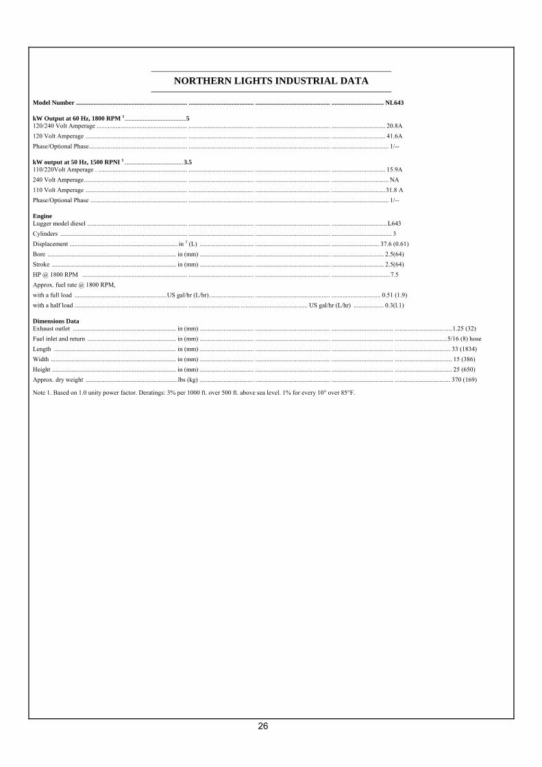
Model Number ...................................................................... ......................................... ............................................... ................................. NL643
kW Output at 60 Hz, 1800 RPM 1..................................................................5 120/240 Volt Amperage ......................................................... ......................................... ............................................... .................................. 20.8A 120 Volt Amperage ................................................................ ......................................... ............................................... .................................. 41.6A Phase/Optional Phase.............................................................. ......................................... ............................................... .................................... 1/--
kW output at 50 Hz, 1500 RPNI 1 ............................................................... 3.5 110/220Volt Amperage . ........................................................ ......................................... ............................................... .................................. 15.9A 240 Volt Amperage................................................................. ......................................... ............................................... .................................... NA 110 Volt Amperage ................................................................ ......................................... ............................................... ..................................31.8 A Phase/Optional Phase ............................................................. ......................................... ............................................... .................................... 1/--
Engine Lugger model diesel ............................................................... ......................................... ............................................... ...................................L643 Cylinders ................................................................................ ......................................... ............................................... ...................................... 3 Displacement .................................................................... in 3 (L) .................................. ............................................... .............................. 37.6 (0.61) Bore ................................................................................. in (mm) .................................. ............................................... ................................. 2.5(64) Stroke .............................................................................. in (mm) .................................. ............................................... ................................. 2.5(64) HP @ 1800 RPM .................................................................. ......................................... ............................................... .....................................7.5 Approx. fuel rate @ 1800 RPM, with a full load ..........................................................US gal/hr (L/hr) ............................ ............................................... ............................... 0.51 (1.9) with a half load ....................................................................... ................................ .......................................... US gal/hr (L/hr) ................... 0.3(l.1)
Dimensions Data Exhaust outlet ................................................................. in (mm) .................................. ............................................... ....................................... ....................................1.25 (32) Fuel inlet and return ........................................................ in (mm) .................................. ............................................... ....................................... .................................5/16 (8) hose Length ............................................................................. in (mm) .................................. ............................................... ....................................... ................................... 33 (1834) Width ............................................................................... in (mm) .................................. ............................................... ....................................... .................................... 15 (386) Height .............................................................................. in (mm) .................................. ............................................... ....................................... .................................... 25 (650) Approx. dry weight ..........................................................lbs (kg) .................................. ............................................... ....................................... ................................... 370 (169)
Note 1. Based on 1.0 unity power factor. Deratings: 3% per 1000 ft. over 500 ft. above sea level. 1% for every 10° over 85°F.
NORTHERN LIGHTS INDUSTRIAL DATA
27
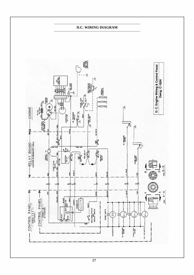
D.C. WIRING DIAGRAM

28
A.C. WIRING DIAGRAM