Embed Size (px)
Citation preview
Operator’s Manual
Table of Contents
Introduction . . . . . . . . . . . . . . . . . . . . . . . . . . . . . . . . . . . . . . . . . . . . . . . . .2
Warranty . . . . . . . . . . . . . . . . . . . . . . . . . . . . . . . . . . . . . . . . . . . . . . . . . . . .2
Safety . . . . . . . . . . . . . . . . . . . . . . . . . . . . . . . . . . . . . . . . . . . . . . . . . . . . . .3
Operating Procedures . . . . . . . . . . . . . . . . . . . . . . . . . . . . . . . . . . . . . . . . .4
Maintenance . . . . . . . . . . . . . . . . . . . . . . . . . . . . . . . . . . . . . . . . . . . . . . . . .7
Troubleshooting . . . . . . . . . . . . . . . . . . . . . . . . . . . . . . . . . . . . . . . . . . . . . .9
Parts Diagrams . . . . . . . . . . . . . . . . . . . . . . . . . . . . . . . . . . . . . . . . . . . . . .10
Van Layout . . . . . . . . . . . . . . . . . . . . . . . . . . . . . . . . . . . . . . . . . . . . . . . . . .19
©2014 MasterBlend, Inc. Denver, CO 80216 USA. All Rights Resevered
2 Operator’s Manual
MasterBlend warrants the El Diablo HE to be free from
defects in materials and workmanship when properly operated
and maintained in accordance with our Operating and
Maintenance instructions. This warranty shall be for periods as
listed. Components, parts, and accessories furnished by other
manufacturers are warranted only to the extent of their original
manufacturers’ warranty. The warranty obligation shall extend
from the date of sale to the original purchaser or lessee only.
During the warranty period, we will either repair or replace, at our
sole option, any part found to be defective upon our examination.
This warranty does not cover normal wear items such as
hoses, filters, gaskets, quick disconnects or other parts that may
require replacement during normal use. Parts that have been
abused or damaged by neglect or freezing conditions will not be
warranted. Damage to materials and components due to the use
of improper lubricants, chemicals or deposits from poor water
quality will not be warranted. There is no warranty on pump or
valve seals and o-rings. This warranty does not cover labor, ship-
ping charges, or any other charges in connection with the
replacement of defective parts.
This warranty is for the replacement of defective parts or
workmanship only. It does not provide in any way for the
replacement of entire units due to defective parts or workman-
ship. This warranty service is an exclusive remedy and
MasterBlend will not be liable for any special, indirect, incidental
or consequential damages or injury to person or property of any
type.
Machine Frame . . . . . . . . . . . . . . . . . . . . . . . . . . . . . . . .3 years
(excluding paint and abuse or neglect)
Waste Tank . . . . . . . . . . . . . . . . . . . . . . . . . . . . . . . . . . .3 years
(excluding paint and abuse or neglect)
Engine . . . . . . . . . . . . . . . . . . . . . . . . . . . . . . . . . . . . . . 3 years
(through original manufacturers’ warranty)
Blower . . . . . . . . . . . . . . . . . . . . . . . . . . . . . . . . . . . . . . 2 years
(through original manufacturers’ warranty)
Water pump . . . . . . . . . . . . . . . . . . . . . . . . . . . . . . . . . . 2 years
All other components including seals, o-rings, belts, and electri-
cal components are covered for 2 years.
The above Limited Warranty Applies only to the
El Diablo HE Truckmount
Truck Mount Limited Warranty Effective January 1, 2013
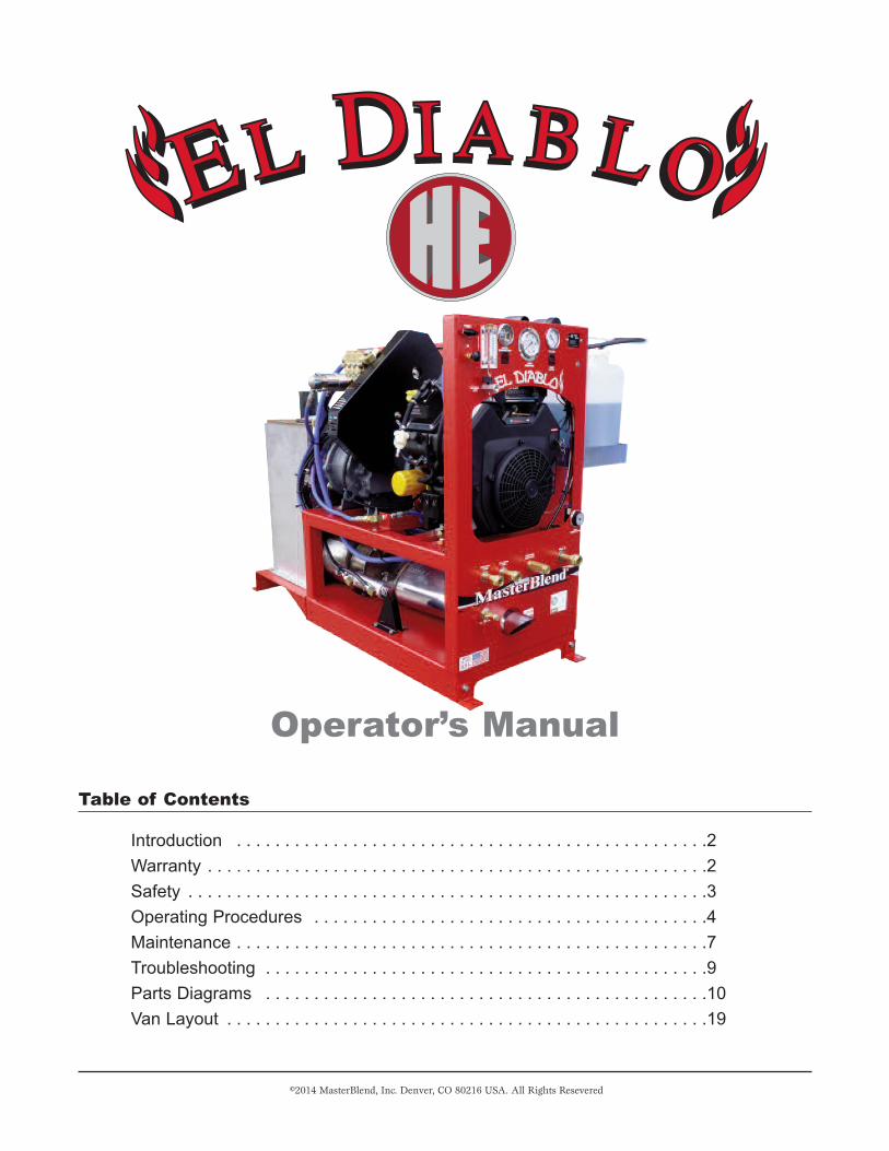
Congratulations and thank you for purchasing the ELDIABLO HE truck mounted cleaning system. The ELDIABLO HE has been designed with simplicity and dura-bility in mind to give you many years of reliable service.Years of experience, engineering, planning, and practicalknow-how have gone into the design and manufacture ofthe EL DIABLO HE. This manual is intended to informyou about the operation and maintenance of your newtruck mount. Please take time to read this manual tobecome familiar with the machine’s operating and mainte-nance procedures. This will be time well spent to help giveyou years of reliable service from your EL DIABLO HE.
Please read this manual before operating or maintaining
your equipment.
It is recommended that all persons who will be operating or
maintaining this equipment should be familiar with this manual.
Failure to follow proper procedures could result in damage to the
equipment or severe personal injury.
This equipment must be operated only in a well ventilated
environment.
The engine produces carbon monoxide which is an odorless
and colorless poison gas.
Do Not operate this machine inside an enclosed area or where
the exhaust fumes could enter a building through an open door,
window, or another opening.
This equipment has moving parts.
Keep your hands, hair, loose clothing, or any other items
away from all moving or rotating parts. Do Not service the
equipment while it is operating. Do Not operate the equipment
without the safety guards in place. Serious injury may result.
This equipment has hot surfaces.
The components of the machine will be extremely hot dur-
ing and shortly after operation. Do Not touch any suspected hot
areas of the machine without allowing sufficient time for cool
down.
This equipment uses Gasoline.
Store fuels in approved containers. Keep away from sparks
or open flames. If an odor of gasoline is present, Do Not turn on
the equipment or any other accessories until the source of the
odor is controlled and the fumes are dissipated.
This equipment contains electrical power sources.
12vdc battery:
Batteries can give off explosive gasses that can be ignited
by sparks or any ignition source. Use caution when working with
or around batteries. Disconnect the negative terminal of the bat-
tery before performing repairs to the equipment. Make sure all
electrical components are turned off before connecting or discon-
necting the battery to avoid a spark at the cable and battery ter-
minal connection.
High pressure and high temperature water
This machine is capable of producing 2000 psi water pres-
sure and 250˚F + water temperature. All hoses must be capable
of withstanding these ranges. Make sure the pressure and tem-
perature are adjusted properly for the cleaning tool being used.
Severe injury may occur if caution is not observed while using
high pressure and temperature.
Cleanliness
The machine area must be kept clean and free of foreign
material that may interfere with the normal operation and safety
of the machine.
Training of operators
This machine must only be operated by qualified persons
who have read this manual and understand the operating char-
acteristics of the machine. Improperly trained persons may dam-
age the equipment or cause personal injury.
El Diablo HE (Heat Exchange) Truck Mount 3
Safety
4 Operator’s Manual
The El Diablo HE truck mount unit must be securely
bolted through the floor of the vehicle in which it is
installed. Serious damage to the equipment or personal
injury may occur if the machine is not mounted properly.
The El Diablo HE truck mount weighs approximately
700lbs. The use of a forklift is required when lifting the machine
into a vehicle. It is also strongly recommended that a second
person be utilized to stabilize the machine while it is on the fork-
lift, due to the center of gravity being heavy to the waste tank
side of the machine. Use caution when moving the machine
with the forklift to avoid damage to equipment, the vehicle
and personal injury.
The El Diablo HE truck mount can be installed into a ½ ton
or larger van; however, it is strongly recommended that it be
installed into a ¾ ton or larger van. The machine can be
installed in either the side door or rear door of the van. If the
machine is installed into the rear doors a vacuum hose reel may
be installed next to the machine to maximize van floor space
(See page 19).
Due to irregularities in the van floor it is suggested that
wood be placed under the machine to provide a level surface on
which the machine is mounted. The wood should be ½ “or ¾”
exterior grade plywood or equivalent.
The El Diablo HE has 2 “L” - shaped mounting brackets on
the front of the machine and holes pre-drilled into the rear of the
water box support on the back of the machine to be used for
mounting. There are also mounting tabs on the base of the
waste tank that can be used if the situation permits.
Before drilling holes in the van floor, check to ensure
that underneath the van floor there are no fuel lines, brake
lines, or other obstructions that could cause a safety haz-
ard. Use 3/8” bolts to secure the machine to the van floor. Lock
washers and large fender washers are recommended to be used
underneath the van. Tighten the bolts until the machine is
securely mounted to the floor.
The engine on the El Diablo HE runs on gasoline, there-
fore, it is recommended that the vehicle’s gasoline fuel tank be
accessed. There are several fuel tank hook-up kits available
from your supplier for each specific model of vehicle. It is rec-
ommended that the fuel hook-up kit be installed by only
qualified mechanics familiar with this type of modification.
If the equipment is to be installed into a trailer, make sure
that the fuel is stored in a proper tank and connected to the
machine according to federal, state and local regulations.
Installation
Operating Procedures
NOTE: It is strongly recommended that a water soft-
ening system be used. It is highly likely that the water
in your area is considered hard. Hard water is water
that has a high mineral content. Your local water sup-
ply can be tested to determine the hardness. If the
water hardness is determined to be greater that 3.5
grains, a water softening system should be used.
Continued and prolonged use of the machine with
hard water will cause excessive scale buildup that
reduces heating and water flow performance. Hard
water also detracts from the performance and effec-
tiveness of the cleaning solutions.
Check oil levels
Make sure that the engine oil level is in the operating range
of the dipstick. Inspect the oil sight gauges on the Cat Pump and
the Roots blower to insure correct level of oil. Operating the
equipment with improper oil levels can cause damage to the com-
ponents that is not covered under warranty. (See the
Maintenance section for the proper oil to be used in the engine,
blower, and the pump.)
Check fuel levels
Make sure that there is an adequate supply of gasoline in
the gas tank to finish the job. If you are connected to the gaso-
line tank of the van, it is suggested that the level of fuel be no
less than ½ tank to avoid running the van out of fuel and being
stranded.
Check cleaning solution
Inspect the cleaning solution container to assure adequate
level of the proper cleaning solution desired, and also that it is
the correct cleaning solution for the job.
Connect hoses to machine
Connect the water supply hose to the water input connec-
tion on the front of the machine. Before connecting the hose to
the customer’s water supply, it is suggested that the faucet be
turned on to flush out any debris that may have accumulated,
and also to assure an adequate amount of water is supplied from
the faucet.
Take the vacuum and pressure hoses into the building to
the furthest point that you are going to clean. Connect the hoses
to the cleaning tool, and then connect the vacuum hose to the
vacuum connection on the waste tank lid and the pressure hose
to the pressure out connection on the front of the machine.
Start the engine
Secure the doors of the van so they will not close during
machine operation. Turn the key switch to the “Start” position, and
hold until the engine starts. (If the engine does not start within 5
seconds, release the key and wait 10 seconds before trying to
restart). When the engine starts, release the key switch. If the
engine stalls, check the oil level to assure proper level, and then
repeat the starting procedure. This engine is equipped with an oil
safety shut down that will stop the engine if proper oil level or
pressure is not up to a safe level. If, after 2 or 3 starting
attempts, the engine still stalls, check the oil level then con-
tact your distributor or local service center for assistance.
DO NOT CONTINUE TO OPERATE THE MACHINE OR SERI-
OUS ENGINE DAMAGE WILL RESULT THAT IS NOT COV-
ERED UNDER WARRANTY. Allow the engine to run at a low rpm
for a couple of minutes to warm up, and then move the throttle
lever to the fast position.
Turn on the water pump
Turn the Pump Clutch switch on to engage the water pump
for pressure. The water pressure gauge should begin to register
pressure within 5 to 10 seconds. If the gauge does not begin to
read pressure, turn the Pump Clutch switch to the off position and
refer to the troubleshooting section. Do not continue to operate
the pump without pressure showing on the pressure gauge
or serious pump damage will occur that is not covered under
warranty. Pump seal damage will occur.
FOR WATER EXTRACTION ONLY, DO NOT TURN ON THE
WATER PUMP!
Set water pressure
Set the water pressure at the desired pressure for the
cleaning job. Adjust the water pressure by turning the pressure
regulator knob on the front of the machine. Suggested water
pressure setting for carpet cleaning is around 400 psi and hard
surface cleaning around 1000 psi, or as recommended by the
tool manufacturer. When setting the pressure for cleaning uphol-
stery, check the recommended pressure for the specific tool you
are using.
Set cleaning solution level
Make sure that the hoses for the cleaning solution are fully
inserted into the cleaning solution bottle. Turn the solution selec-
tor valve to PRIME and observe that there is flow thru the solu-
tion meter. If no flow is observed thru the meter within 20-30
seconds, the solution system pump may need to be primed. To
prime the system, remove the black hose from the solution bottle
and insert it into the vacuum hose connection on the waste tank.
Using your hand, block off the vacuum port to create a suction
on the hose. The cleaning solution will then begin to flow thru the
meter. Insert the hose back into the solution bottle.
Adjust the cleaning solution level by turning the solution
selector valve to ON then activate the cleaning tool and adjust
the amount of cleaning solution by turning the black adjustment
knob until the desired amount of cleaning solution is registered
on the meter.
Set Thermostat
Set the thermostat to the desired temperature for the job.
Please Note: There must be at least 8”hg vacuum on the
gauge for the diverter system to work properly. This is usual-
ly achieved when the vacuum hoses are connected to the
machine and the cleaning tool. Allow the machine to run for sev-
eral minutes with the vacuum hose connected to the machine
and the cleaning tool to preheat the water. To maintain maxi-
mum cleaning temperatures it is recommended that the total jet
orifice size on the cleaning tool does not exceed #4 (example: 2
- # 2 jets or 4 - #1 jets).
Water Extraction
When the need to perform water extraction only arises, DO
NOT TURN ON THE WATER PUMP SWITCH! Adjust the ther-
mostat to it lowest position. The diverter system is activated by
the water pump switch and the thermostat.
Complete the cleaning job
After the previous steps have been completed, continue
with the normal cleaning procedures as required by the job.
During operation, occasionally check out the gauges on the
machine to assure that the settings that were previously done
are still correct, i.e. water pressure and temperature, engine rpm,
solution metering, etc. Adjust as necessary.
El Diablo HE (Heat Exchange) Truck Mount 5
Operating Procedures (continued)
6 Operator’s Manual
Turn off the thermostat and solution meter
Adjust the thermostat to the lowest setting and flush fresh
water thru the cleaning solution system to remove the possibility
of any residue left in the wand and hoses. Continue to run the
machine until the water temperature is 150ºF or lower. This will
reduce the residual heat left in the system.
Turn off the water pump
Turn off the Pump Clutch switch and activate the cleaning
tool to release pressure in the hoses.
Turn off the engine
Move the throttle lever to idle. Allow the engine to run for
several minutes to cool down. On the last job of the day, spray
WD-40 (or an equivalent) for 5 to 10 seconds into the Blower
Lube located on the upper front panel. (Note: When spraying
the WD 40 the engine should be at operating speed and a vacu-
um load applied by blocking off the vacuum port on the waste
tank or the vacuum hose if it is still connected to the waste tank.)
Turn the key switch to off.
Retrieve and store cleaning tools and hoses
Make sure all hoses, cleaning tools and accessories that
were used on the job are properly stored in the vehicle.
Empty waste tank
When emptying the waste tank, follow local, state, and fed-
eral laws concerning waste water disposal. Waste water should
be disposed of only into drain systems that connect to a munici-
pal sanitary sewage treatment plant!
Make sure the engine is turned off before draining the
waste tank. Connect the drain hose to the drain valve on the
waste tank and open the valve. Remove the waste tank lid and
lift out the lint basket and clean out any debris that has accumu-
lated then reinstall basket in tank. Inspect the blower lint screen
for any build up of debris. Remove and clean screen then re
install. Do not operate machine without the blower lint screen
installed or serious damage to the blower will occur that is not
covered under warranty.
Rinse out the waste tank at the end of the cleaning day
using fresh water to prevent an accumulation of debris in the bot-
tom.
Shutdown Procedures
DO NOT PERFORM ANY MAINTENANCE PROCEDURES
WHILE THE EqUIPMENT IS RUNNING. MOVING PARTS AND
HOT COMPONENTS MAY CAUSE PERSONAL INjURY OR
DAMAGE TO COMPONENTS.
This section of your machine manual may very well be the
most important section of the manual that you read. The proper
care and maintenance of your El Diablo truck mount is essential
for a safe and reliable long life to your investment.
Engine
Check the engine oil level daily when the engine is turned
off and is in a level position. The oil level should be between the
upper limit and the low limit marks on the dipstick. Operating
the engine with improper oil level can cause engine damage
that is not covered under warranty.
Change the oil after the first 20 hours and then every 100
hours thereafter. Use 10 W-30 with an API SERVICE CATEGO-
RY SJ or higher motor oil (see Kohler owners manual). The
engine holds approximately 2 US qts with an oil filter change. . It
is recommended that the oil be warm so it will drain more quickly
and efficiently.
Change the oil filter at least every 200 hours. Use only a
genuine Kohler oil filter or a filter of equivalent quality specified
for your engine model. Check the air filter every 50 hours and
replace as necessary. Replace the spark plugs every 500 hours.
For more specific engine maintenance procedures see the
Kohler Engine Owners Manual. Use only clean, fresh unleaded
gasoline.
Blower
The El Diablo uses a Roots URI-J DSL blower that is splash
lubricated by gear oil on both the front and back of the blower.
There are sight gauges on the side of each gear case for check-
ing the oil level. The gear boxes are filled with ROOTS SYN-
THETIC OIL. Use only ROOTS SYNTHETIC OIL to maintain
optimum performance. The gear oil should be changed after
the first 100 hours of operation, then every 1000 hours there-
after. To drain the oil, remove the drain plug in the bottom of the
gear case and allow the oil to drain out. It is recommended that
the oil be warm so it will drain more quickly and efficiently. To
refill the gear case, remove the top plug and fill until the oil
reaches the middle of the oil sight gauge on the side of the gear
case. The front and rear gear case must be serviced individual-
ly.
At the end of each working day, lubricate the lobes in the
blower by spraying WD-40 (or equivalent) for 5 to 10 seconds
into the Blower Lube located on the front panel of the
machine.(Note: When spraying the WD 40 the engine should be
at operating speed and a vacuum load applied by blocking off
the vacuum port on the waste tank or the vacuum hose if it is still
connected to the waste tank.) If the blower is going to be shut
down for an extended time, it is especially important that this be
done to protect the lobes from rusting.
Cat Pump
The crank case on the Cat Pump is filled with special CAT
PUMP CRANKCASE OIL. The oil should be changed after the
first 50 hours of operation then every 500 hours thereafter. Use
only CAT PUMP CRANKCASE OIL to maintain optimum per-
formance. The oil level should be at the middle to the top of the
red dot in the oil sight gauge located on the pump housing.
Belt and Coupler
Belt tension is adjusted by first removing the belt guard.
Then loosen the tensioner mounting bolt. Move the tensioner
away from the pump to increase belt tension. Tighten the
mounting bolts. Reinstall the belt guard.
A spare belt is already installed at the factory. To install a
new spare belt or to replace the coupler sleeve, loosen the ten-
sioner as previously described above, and then loosen the two
set screws in the engine coupling flange. The flange will slide on
the shaft to open up a gap in the coupler assembly to allow a
new belt or coupler sleeve to be installed.
El Diablo HE (Heat Exchange) Truck Mount 7
Maintenance
8 Operator’s Manual
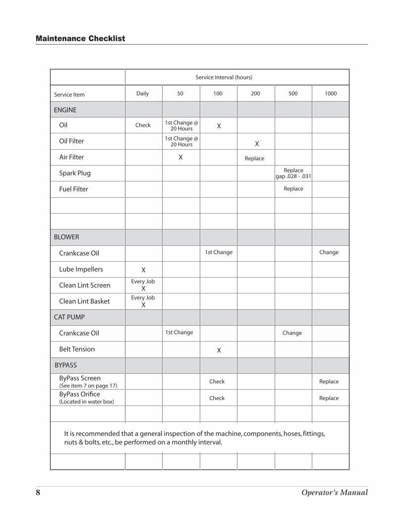
Service Item Daily 50 100 200 500 1000
Service Interval (hours)
ENGINE
Oil
Oil Filter
Air Filter
Spark Plug
Fuel Filter
BLOWER
Crankcase Oil
Lube Impellers
Clean Lint Screen
Clean Lint Basket
CAT PUMP
Crankcase Oil
Belt Tension
ByPass Screen(See item 7 on page 17)
Check
Every Job
Replace
Replace
Replacegap .028 - .031
1st Change @20 Hours
1st Change @20 Hours
1st Change
1st Change Change
Change
X
X
XEvery Job
X
X
X
X
Check Replace
ByPass Ori!ce(Located in water box) Check Replace
It is recommended that a general inspection of the machine, components, hoses, fittings, nuts & bolts, etc., be performed on a monthly interval.
BYPASS
Maintenance Checklist
El Diablo HE (Heat Exchange) Truck Mount 9
Engine
Hard starting or won’t start Check fuel in fuel tank to assure proper level and not contaminated.
Check fuel pump for operation.
Check for proper oil level.
Check battery and battery connections. Make sure they are clean and tight and battery is
charged.
Check fuse located on side of engine. Replace if blown.
Check waste tank water level. Drain if necessary.
Check waste tank float switch to make sure it is not stuck.
Inspect spark plugs and spark plug wires. Clean or replace spark plugs if necessary.
Engine runs but loses power Check fuel for good quality.
Check fuel filter. Replace if restricted.
Check air filter for cleanliness. Replace if necessary.
Check spark plugs for proper gap and condition.
Make sure waste tank lint screen is clean.
Check engine oil level.
Check fuel pump for proper operation.
Vacuum
Vacuum is weak Make sure waste tank lint screen is clean.
Check that the waste tank lid is on properly.
Check to make sure the waste tank gasket is in good shape.
Check to make sure the waste tank drain valve is closed.
Check the vacuum hoses and cleaning tool for clogs.
Make sure engine is at proper operating rpm (3000).
Check waste tank inlet and lint basket for restrictions.
Water Pressure
Low or no water pressure on gauge Check incoming water supply for sufficient volume and pressure.
Check float in water tank to make sure it is not stuck or clogged.
Check level of cleaning solution in solution container and make sure hose is below solution
level.
Check to make sure the pump clutch is engaging.
Check pump belt tension to make sure it is not slipping.
Check adjustment of pressure regulator to make sure it has not backed off.
Check jets on cleaning tool for correct size and excessive wear of opening.
Check filter screen in bottom of fresh water tank.
Low water pressure at tool Jet on cleaning tool partially clogged.
but good pressure on gauge Quick disconnects on hoses worn and not making good connection.
Pressure hoses between machine and cleaning tool damaged or restricted.
Bad valve on cleaning tool.
Heating coil has scale build-up.
Troubleshooting
DO NOT PERFORM ANY MAINTENANCE PROCEDURES WHILE THE EqUIPMENT IS RUNNING. MOVING PARTS
AND HOT COMPONENTS MAY CAUSE PERSONAL INjURY OR DAMAGE TO COMPONENTS MAY OCCUR.
10 Operator’s Manual
Waterflow Diagram
CAT
Pum
p
12
3 4
5
35
28
30
29
27
26
2524
27
33
27
31
2221 23
37
732
34
3612
11
31
1819
20
171615
14
89
10
36
6
35
13
39
38
El Diablo HE (Heat Exchange) Truck Mount 11
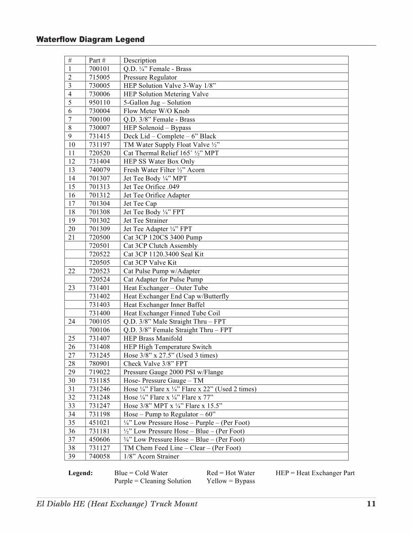
Waterflow Diagram Legend
# Part # Description
1 700101 Q.D. !” Female - Brass
2 715005 Pressure Regulator
3 730005 HEP Solution Valve 3-Way 1/8”
4 730006 HEP Solution Metering Valve
5 950110 5-Gallon Jug – Solution
6 730004 Flow Meter W/O Knob
7 700100 Q.D. 3/8” Female - Brass
8 730007 HEP Solenoid – Bypass
9 731415 Deck Lid – Complete – 6” Black
10 731197 TM Water Supply Float Valve "”
11 720520 Cat Thermal Relief 165˚ "” MPT
12 731404 HEP SS Water Box Only
13 740079 Fresh Water Filter "” Acorn
14 701307 Jet Tee Body !” MPT
15 701313 Jet Tee Orifice .049
16 701312 Jet Tee Orifice Adapter
17 701304 Jet Tee Cap
18 701308 Jet Tee Body !” FPT
19 701302 Jet Tee Strainer
20 701309 Jet Tee Adapter !” FPT
21 720500 Cat 3CP 120CS 3400 Pump
720501 Cat 3CP Clutch Assembly
720522 Cat 3CP 1120.3400 Seal Kit
720505 Cat 3CP Valve Kit
22 720523 Cat Pulse Pump w/Adapter
720524 Cat Adapter for Pulse Pump
23 731401 Heat Exchanger – Outer Tube
731402 Heat Exchanger End Cap w/Butterfly
731403 Heat Exchanger Inner Baffel
731400 Heat Exchanger Finned Tube Coil
24 700105 Q.D. 3/8” Male Straight Thru – FPT
700106 Q.D. 3/8” Female Straight Thru – FPT
25 731407 HEP Brass Manifold
26 731408 HEP High Temperature Switch
27 731245 Hose 3/8” x 27.5” (Used 3 times)
28 780901 Check Valve 3/8” FPT
29 719022 Pressure Gauge 2000 PSI w/Flange
30 731185 Hose- Pressure Gauge – TM
31 731246 Hose !” Flare x !” Flare x 22” (Used 2 times)
32 731248 Hose !” Flare x !” Flare x 77”
33 731247 Hose 3/8” MPT x !” Flare x 15.5”
34 731198 Hose – Pump to Regulator – 60”
35 451021 !” Low Pressure Hose – Purple – (Per Foot)
36 731181 "” Low Pressure Hose – Blue – (Per Foot)
37 450606 #” Low Pressure Hose – Blue – (Per Foot)
38 731127 TM Chem Feed Line – Clear – (Per Foot)
39 740058 1/8” Acorn Strainer
Legend: Blue = Cold Water Red = Hot Water HEP = Heat Exchanger Part
Purple = Cleaning Solution Yellow = Bypass
12 Operator’s Manual
Bat
tery
Tran
sfer
Pum
p (O
pti
ona
l)
Fuel
Pum
p
Hig
h P
ress
ure
So
leno
id
Yello
w
Fro
m
Eng
ine
The
rmo
stat
Black
White
White White
Whi
te
Pum
pC
lutc
h
Mac
Valv
e
Ele
ctri
cal D
iag
ram
(Bac
k si
de
of
pan
el)
Bla
ck
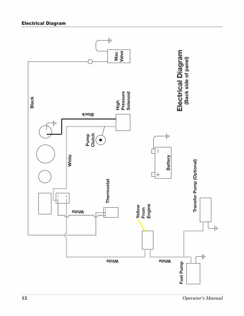
Electrical Diagram
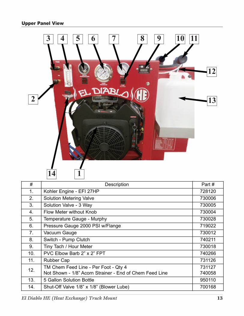
El Diablo HE (Heat Exchange) Truck Mount 13
# Description Part #
1. Kohler Engine - EFI 27HP 728120
2. Solution Metering Valve 730006
3. Solution Valve - 3 Way 730005
4. Flow Meter without Knob 730004
5. Temperature Gauge - Murphy 730028
6. Pressure Gauge 2000 PSI w/Flange 719022
7. Vacuum Gauge 730012
8. Switch - Pump Clutch 740211
9. Tiny Tach / Hour Meter 730018
10. PVC Elbow Barb 2” x 2” FPT 740266
11. Rubber Cap 731126
12.TM Chem Feed Line - Per Foot - Qty 4
Not Shown - 1/8” Acorn Strainer - End of Chem Feed Line
731127
740058
13. 5 Gallon Solution Bottle 950110
14. Shut-Off Valve 1/8” x 1/8” (Blower Lube) 700168
14 1
Upper Panel View
3 4 5 6 7 8 9 10 11
12
132
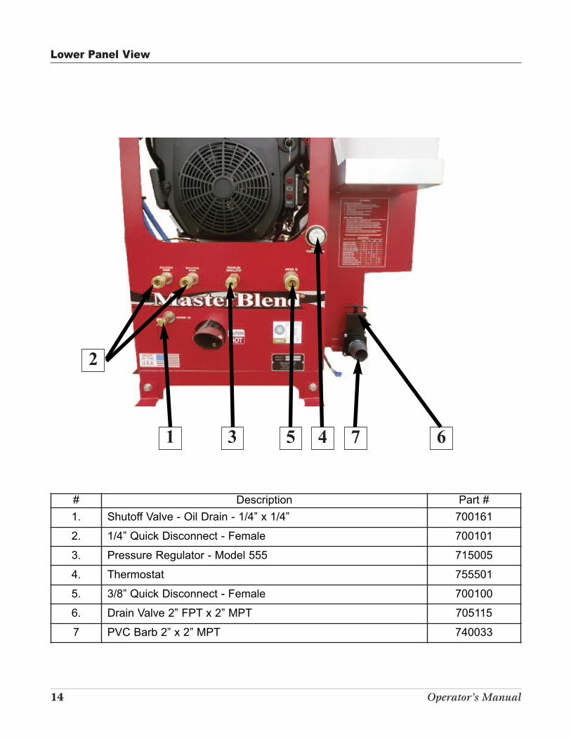
14 Operator’s Manual
# Description Part #
1. Shutoff Valve - Oil Drain - 1/4” x 1/4” 700161
2. 1/4” Quick Disconnect - Female 700101
3. Pressure Regulator - Model 555 715005
4. Thermostat 755501
5. 3/8” Quick Disconnect - Female 700100
6. Drain Valve 2” FPT x 2” MPT 705115
7 PVC Barb 2” x 2” MPT 740033
2
1 3
Lower Panel View
5 4 7 6
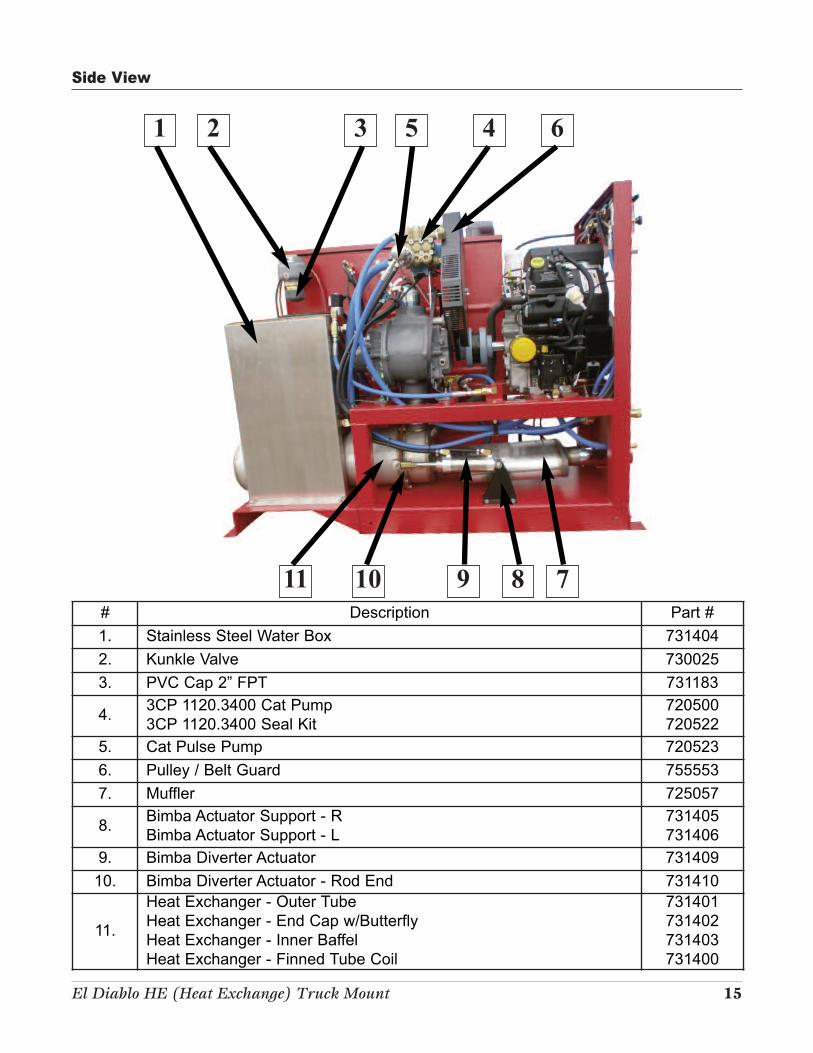
El Diablo HE (Heat Exchange) Truck Mount 15
# Description Part #
1. Stainless Steel Water Box 731404
2. Kunkle Valve 730025
3. PVC Cap 2” FPT 731183
4.3CP 1120.3400 Cat Pump
3CP 1120.3400 Seal Kit
720500
720522
5. Cat Pulse Pump 720523
6. Pulley / Belt Guard 755553
7. Muffler 725057
8.Bimba Actuator Support - R
Bimba Actuator Support - L
731405
731406
9. Bimba Diverter Actuator 731409
10. Bimba Diverter Actuator - Rod End 731410
11.
Heat Exchanger - Outer Tube
Heat Exchanger - End Cap w/Butterfly
Heat Exchanger - Inner Baffel
Heat Exchanger - Finned Tube Coil
731401
731402
731403
731400
3 4 6
11
Side View
10 9 8 7
21 5
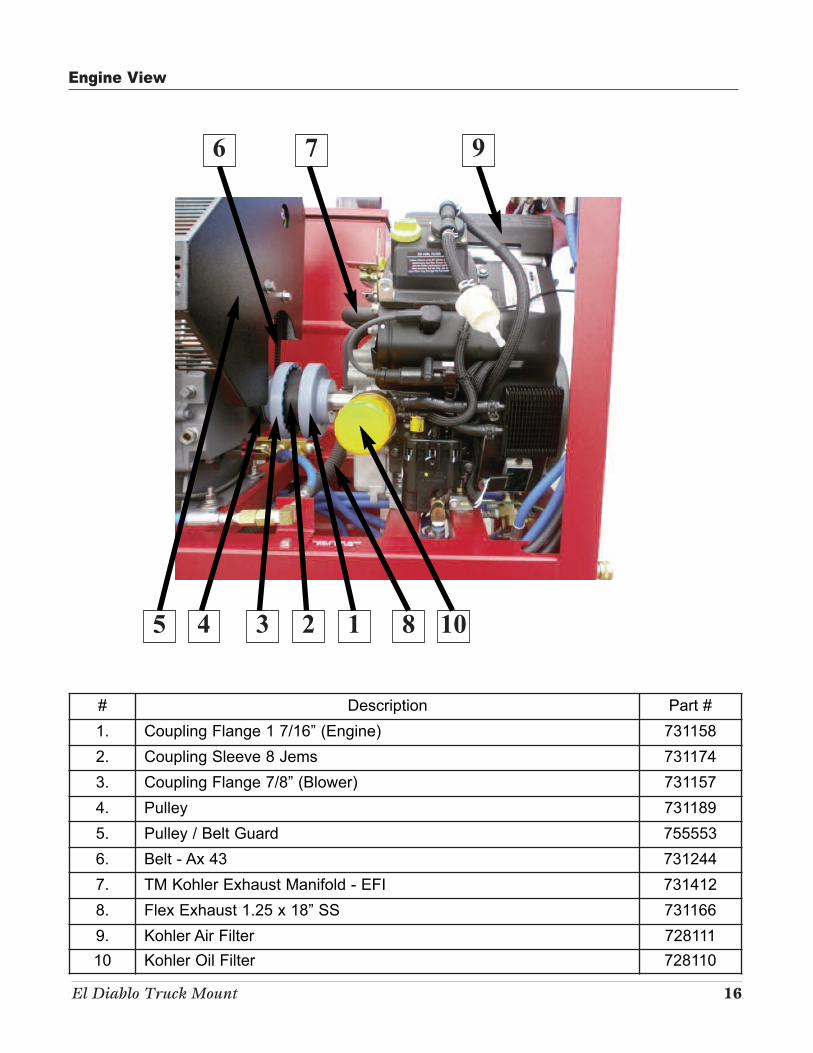
El Diablo Truck Mount 16
# Description Part #
1. Coupling Flange 1 7/16” (Engine) 731158
2. Coupling Sleeve 8 Jems 731174
3. Coupling Flange 7/8” (Blower) 731157
4. Pulley 731189
5. Pulley / Belt Guard 755553
6. Belt - Ax 43 731244
7. TM Kohler Exhaust Manifold - EFI 731412
8. Flex Exhaust 1.25 x 18” SS 731166
9. Kohler Air Filter 728111
10 Kohler Oil Filter 728110
6 7 9
5 4 3
Engine View
2 1 8 10
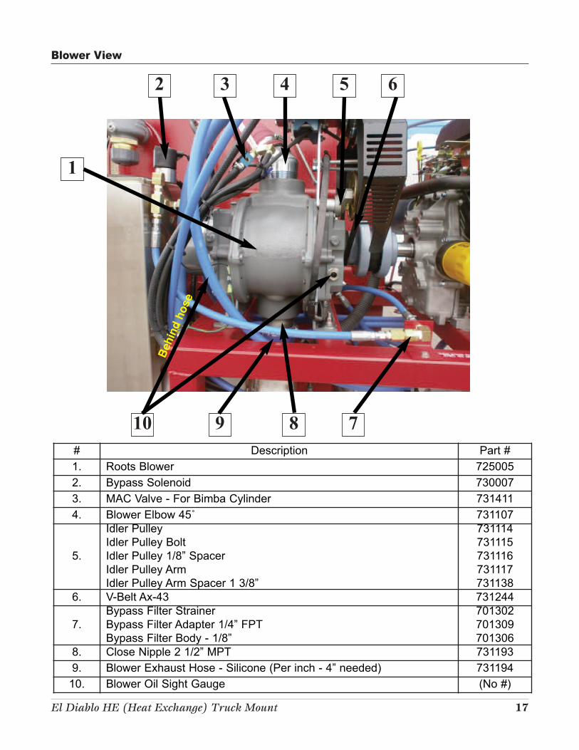
El Diablo HE (Heat Exchange) Truck Mount 17
# Description Part #
1. Roots Blower 725005
2. Bypass Solenoid 730007
3. MAC Valve - For Bimba Cylinder 731411
4. Blower Elbow 45˚ 731107
5.
Idler Pulley
Idler Pulley Bolt
Idler Pulley 1/8” Spacer
Idler Pulley Arm
Idler Pulley Arm Spacer 1 3/8”
731114
731115
731116
731117
731138
6. V-Belt Ax-43 731244
7.
Bypass Filter Strainer
Bypass Filter Adapter 1/4” FPT
Bypass Filter Body - 1/8”
701302
701309
701306
8. Close Nipple 2 1/2” MPT 731193
9. Blower Exhaust Hose - Silicone (Per inch - 4” needed) 731194
10. Blower Oil Sight Gauge (No #)
2 3 4 5 6
1
10 8 7
Beh
ind
ho
se
Blower View
9
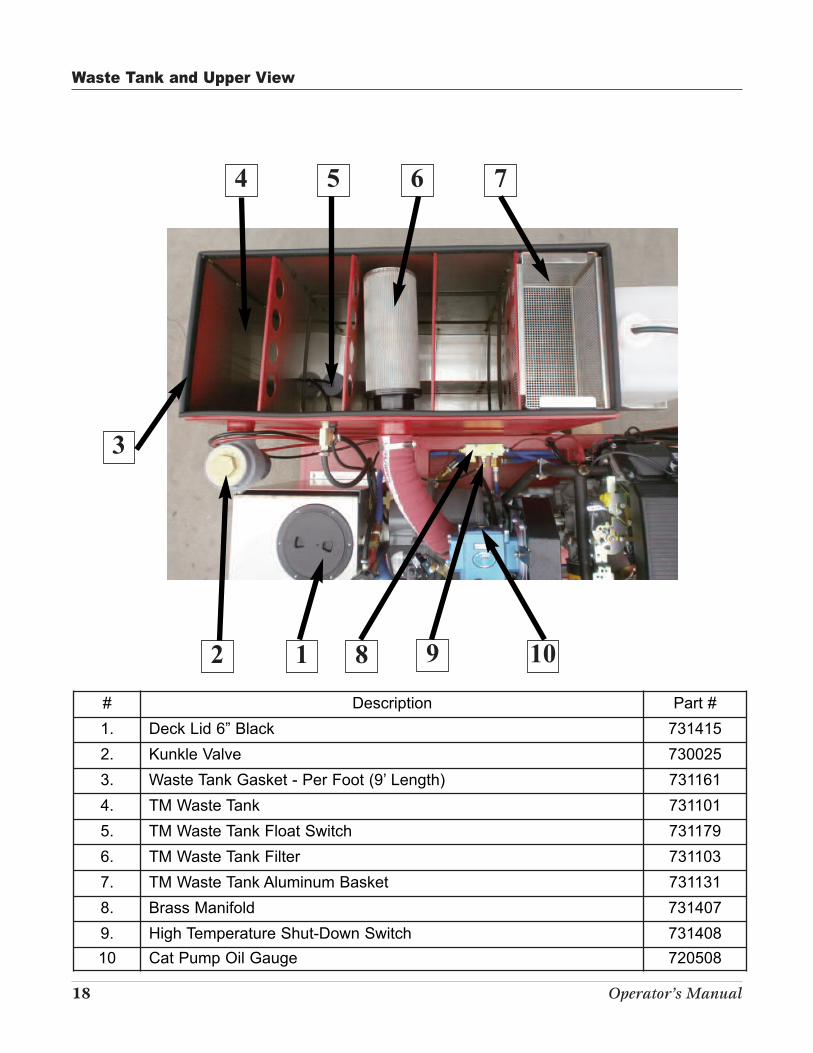
18 Operator’s Manual
# Description Part #
1. Deck Lid 6” Black 731415
2. Kunkle Valve 730025
3. Waste Tank Gasket - Per Foot (9’ Length) 731161
4. TM Waste Tank 731101
5. TM Waste Tank Float Switch 731179
6. TM Waste Tank Filter 731103
7. TM Waste Tank Aluminum Basket 731131
8. Brass Manifold 731407
9. High Temperature Shut-Down Switch 731408
10 Cat Pump Oil Gauge 720508
4 5 6 7
9
3
2 1 8
Waste Tank and Upper View
10
El Diablo HE (Heat Exchange) Truck Mount 19
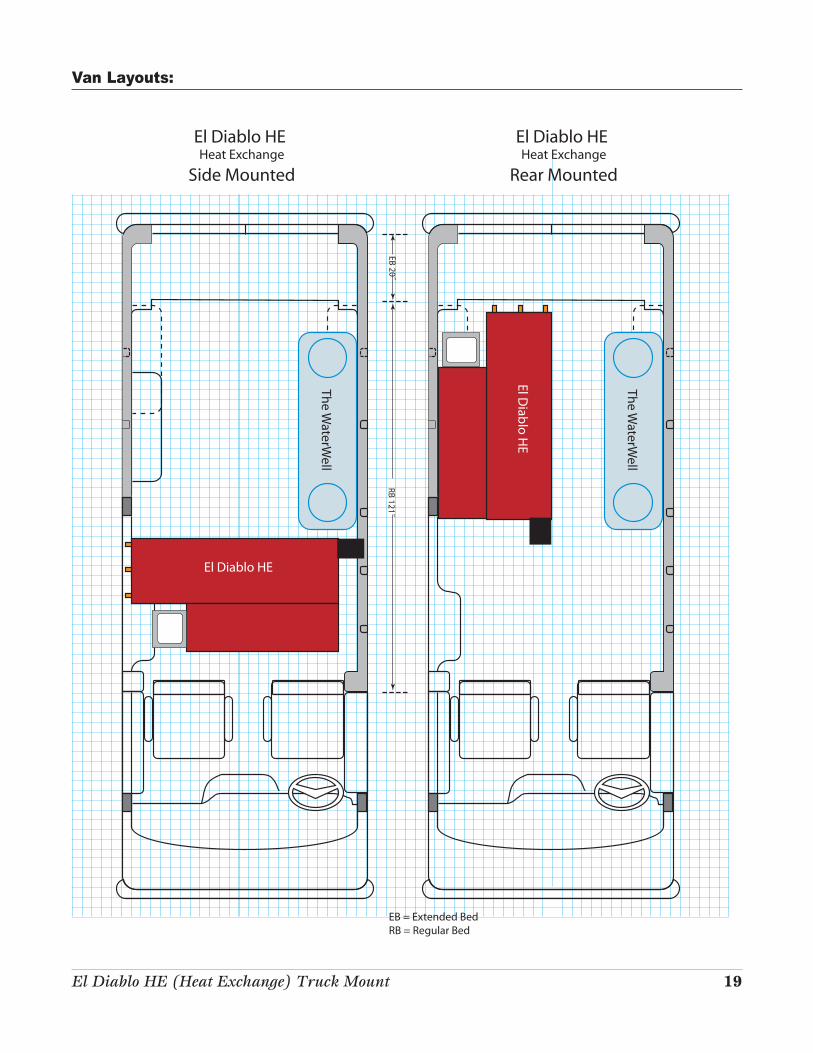
Van Layouts:
The WaterW
ell
RB 121˝EB 20˝
The WaterW
ell
El Diablo HE Heat Exchange
Side Mounted
El Diablo HE Heat Exchange
Rear Mounted
EB = Extended BedRB = Regular Bed
El Diablo H
E
El Diablo HE

5285 Fox Street · Denver, CO 80216
800-525-9644 · 303-373-0702
www.masterblend.net