Embed Size (px)
Citation preview

Operations, Service And Parts Manual
Addendum
RA-300S PatcherManual No. 37679-01

2 RA-300S Patcher
Disclaimer And Copyright
Disclaimer:
All information, illustrations and specifications in this manual are based on the latest information available at the time of publishing. The illustrations used in this manual are intended as representative reference views only. Moreover, because of our continuous product improvement policy, we may modify information, illustrations and/or specifications to explain and/or exemplify a product, service or maintenance improvement. We reserve the right to make any change at any time without notice. VT LeeBoy, Inc., VT LeeBoy, LeeBoy, and Rosco are all the same entity and are used interchangeably.
©2010VTLeeBoy,Inc.
LeeBoy reserves all copyright and other rights in this manual and the manual’s content. No part of this manual may be reproduced or used in any way without the written permission of LeeBoy, except as necessary to operate LeeBoy equipment.
This manual has been most recently updated 03/10 to apply to serial number and above:
PDF file last modified on: 03/24/10
RA-300S Patcher 3
This manual is intended as an addendum guide for the safe and efficient use of the patcher. This manual covers the updated procedures for proper operation and maintenance of the patcher. This manual contains information that was available at the time of printing and is subject to change without notice.
This manual overviews the changes from the RA-300 Patcher model to the RA-300S. The main difference is the redesigned boom. These changes can be found on the following pages and include new images for the RA-300S Patcher, operational changes, and schematics.
If any questions arise concerning this publication or others, contact your local LeeBoy or Rosco Dealer for the latest available information.
Thank you for purchasing the Rosco Model RA-300S Patcher. We wish you many years of safe and efficient operation of your patcher.
READ THIS MANUAL PRIOR TO OPERATING the patcher. This manual is an important part of the patcher and should be kept with the patcher at all times in the dedicated storage container on the patcher. Even though you may be familiar with similar equipment, you MUST read and understand this manual before operating this patcher. Reading the manual will help you and others avoid injury and help prevent any damage to the patcher. If this manual becomes lost or damaged, contact your authorized LeeBoy or Rosco Dealer immediately to order a replacement.
This manual should be used with the RA-300 Patcher manual and all related supplemental books, engine and transmission manuals, and parts books. Related Service Bulletins should be reviewed to provide information regarding some of the recent changes.
Addendum
WARNING LIGHTS
DISCHARGE BOOMTHE PATCHER
PTO FOR BLOWER
EMULSION TANK
RA300
HYDRAULIC TANK
BY
AUXILLIARY ENGINE
WARNING LIGHTS
AGGREGATE HOPPER
SOLVENT TANK
RoscoRA-300SPatcherOverview
Figure 1-1
NOTE: Replaces Figure 5-A in RA-300 Patcher Manual.

4 RA-300S Patcher
5. The boom is controlled with two items. The Joystick(Figure1-3,D) controls the motion of the boom from side to side and also the in and out telescoping of the boom. The BoomUp/Downswitch (Figure1-3,C) controls the up and down movement of the boom by repeated brief toggles in the desired direction.
6. The computer keeps the boom-extension within the working area and away from on-coming traffic by automatically retracting the boom. A manual override toggle switch is located on the side of the gauge panel.
Overridingthesafetyfeaturemaybedangerous.Useextremecautionwhenextendingboomwhenon-comingtrafficisnear.Donotextendboomwhereitcouldbehazardoustoon-comingvehiclesorpersons.Personalinjuryordamagetopropertymayoccur.
BoomWorkingArea
Figure 1-2
Addendum
NOTE: The following replaces pages 5-10 to 5-12 in RA-300 Patcher Manual.
UsingtheController
General
Your unit is equipped with a joystick styled controller. The instructions that follow will explain how the controller works and how to control flow of rock and emulsion. The relay panel for the controller is located behind the passenger seat of the truck. Be sure there is a secure connection between the controller and the relay panel.
Become familiar with your controller and the general working of the unit before attempting any patching work.
TheJoystickController
The joystick (Figure1-3,D) is mounted on a pedestal on the driver’s right side. The controller uses rocker switches and a joystick to control the rock flow, the emulsion flow and the movement of the boom.
1. The hydraulic pump must be engaged to run all hydraulic functions of the RA-300. To start the pump, push the Modebutton(Figure1-3,P)on the Transmission console. A red light will appear on the Transmission console (Figure1-3,R) and on the Gauge panel (Figure1-3,R). To stop the the hydraulic functions, push the Modebutton (Figure1-3,P) again.
2. To start the blower push the Blower1/Oswitch (Figure1-3,E) to the “1” position. The speed of the blower is controlled by rotating the Airknob (Figure1-3,S) on the Gauge panel. The blower is at maximum capacity with engine rpm at 1000. The blower will not put out any more air above 1000 rpm and the PTO will disengage at 1300 rpm. To stop the blower, push the Blower1/Oswitch (Figure1-3,E) to the “O” position.
3. The AirSpeedswitch (Figure1-3,H) controls the mode operation of the blower. The turtle indicates the Patching Mode and the rabbit indicates the Blowout Mode. Air speed is controlled by the Airknob (S). Maximum blower speed is obtained in Blowout Mode.
4. The beacon is activated by pushing the Beacon1/Oswitch (Figure1-3,F) to the “1” position, and turned off by pushing the rocker switch to the “O” position.

RA-300S Patcher 5
Addendum
Joystick,TransmissionandGaugePanels
Figure 1-3

6 RA-300S Patcher
8. The emulsion flow is controlled by the EmulsionSprayswitch (Figure1-3,J) on the top of theJoystick(Figure1-3,D) and a vernier cable, located on the lower left side of the truck dash. The cable should be used to regulate your flow, and the switch (Figure1-3,J) should be used to turn the emulsion on and off.
Emulsion flow is regulated by pressing the knob on the cable and moving the cable in and out. After optimum flow is achieved, turn the knob on the vernier cable to fine tune the flow further. See diagram opposite of decal #38019. Refer to Parts Section for further details and diagram of the vernier cable. To stop the flow, hold the EmulsionSpray switch to the left.
9. The Warninglight (Figure1-3,V) indicates the hydraulic system is overheating and the PTO should be shut down until the heating problem is solved.
7. The rock flow is controlled by two switches. The first switch is the RockOn/Offswitch (Figure1-3,K) which is located on the left side of the Joystick(Figure1-3,D). This switch is activated by pressing and holding the switch UP to open the gate and start the rock flow. Press the switch DOWN and hold it to stop the flow and close the gate. A red light (Figure1-3,T) indicates the rock gate is open.
The second control switch is the RockFlow+/-switch (Figure1-3,G) which will increase or decrease the amount of rock flow only when the gate is open. This switch is a momentary switch. Increase or decrease the amount of rock by pressing the switch briefly in the desired direction and then releasing.
When setting the rock flow, you should first close the gate by pressing DOWN and holding the RockOn/Offswitch (Figure1-3,K). Then press theRockFlow+/-switch (Figure1-3,G) to minus(-) to fully stop any rock flow. Now open the rock gate by pressing UP and holding the RockOn/Offswitch (Figure1-3,K). Press the RockFlow+/-switch (Figure1-3,G) to plus (+) in small increments until the desired rock flow is reached. It will take about 4 seconds after each increase or decrease to notice the change.
Addendum

RA-300S Patcher 7
Addendum
NOTE: The following replaces pages 7-11 to 7-12 in RA-300 Patcher Manual.
BLOWE
R MOT
OR
16 GP
M MA
X
16 GP
M MA
X
#3314
8100
MESH
STRAIN
ER
#2249
020
GAL
RESER
VOIR
900 - 3
000EN
GINE R
PM
CW1.6
6 CIR
1.66 C
IR
CW
25 PSI
D
#3720
610
MICR
ONFIL
TER
#3573
5OIL
COOL
ER
RV10-
22
A250
0 PSI
RELIE
F
B
SV16-
21
1912R
39185
1.50 C
IRD 2A 2A 1
Figure 1-4

8 RA-300S Patcher
Addendum
V08-2
00
2610 GA
GE PO
RT
2610
#3660
4GA
GE PO
RT
.02"
RELIE
F150
0 PSI
APT
B
RV10-
26A
EP10-S
35
XG1
VL100
06
CV04-
20
S2C1
#1003339
S1
G2 X2610
C2
#3806
3
HOIST
FC10-
21A#37467 POSITI
ON
VL100
05
CV04-
20
#3660
4S2C3
#1001185
S1261
0
C4
SWING
CV04-
20
S2C5
#1003340
VL100
05S1C6
.037"
TELESC
OPE
FC10-
21A#3652
3
CV04-
20
S2
C7
#3806
3
VL100
06S1#36519
#3665
4C8
GATE
LID
V08-2
00 CV04-
20
S2C9
VL100
05S1C10
#3652
3
VALVE
MANIF
OLD AS
SEMBLY
#3764
7
Figure 1-5

RA-300S Patcher 9
Addendum
NOTES

10 RA-300S Patcher
NOTE: The following replaces pages 8-12 to 8-13 in RA-300 Patcher Manual.
ControlsGroup-Ref:28663
Addendum
GATE
11
PTO11
CRIMP TERMINALS TOPIGTAILS OF LIGHTS
CONNECT TO GAUGEGROUND ITEM 9
7
PTO DECALCONNECT WHT WIRE TO POSITIVE TERMINAL
9
13
10
6
GATE DECAL
5
1
2
4
8
7
3
14
Figure 1-6

RA-300S Patcher 11
Addendum
ControlsGroup-Ref:28663PartsList
ItemNo. PartNumber Qty. Description Remarks
1 27518 1 MOUNT,GAUGES/CONTROL BOX,W/POT
2 29089 1 HARNESS,GAUGE PANEL,F/L,RA300
3 31983 2 LIGHT,RED,DASH,.50 HOLE
4 33435 1 LIGHT & SOCKET,12V,2.00 GAUGE
5 27519 1 COVER,GAUGES W/POT
6 35385 1 GAUGE,HOUR METER
7 36348 5 TERM,PUSH-ON,.25,M,18-14,SLV
8 81150 2 SCR,SLFTPG,PH,#10X.500,AB
9 37698 1 GAUGE,PRESS,0-15 PSI,02MP
10 37699 1 DECAL,AIR,GAUGE LABEL
11 39017 1 DECAL,GAUGE PANEL,RA300
12 37422 1 TERM,SOLDER SPLICE,20-10 AWG
13 36150 1 ALARM,BUZZ/LIGHT,RED,HYDRA TEMP
14 1
— 280 04 1 CONTROL GRP,POG,GMC,RA300 Includes 3 Following Items
— 28964 1 HARNESS,10K POTENTIOMETER,GMC
— 39019 1 DECAL,POG,POTENTIOMETER
— 72055 1 KNOB,HYD CONTROL

12 RA-300S Patcher
NOTE: The following replaces pages 8-22 to 8-27 in RA-300 Patcher Manual.
DischargeBoomGroup-Ref:24323
Addendum
23
14 10 26 32
30
28 19
5 9 20
1
31
41 42
2
4
38
3
11 3433
22
25
29
17
18 12 1315
21
24
27
Figure 1-7

RA-300S Patcher 13
Addendum
DischargeBoomGroup-Ref:24323PartsList
ItemNo. PartNumber Qty. Description Remarks
1 1001457 1 W/M,BUMPER,HORIZ BOOM,NISAN
2 1000926 1 SUPP,RH,FRT BUMPER,RA300,NISAN
3 1000927 1 SUPP,LH,FRT BUMPER,RA300,NISAN
4 1000948 1 W/M,GUIDE,HOSE,RA300 BUMPER
5 1003338 1 W/M,BOOM PIVOT,RA400
6 32833 2 BUSHING,1.503ID,1.754OD,1.5
7 36613 1 BEARING,THRUST 1.50 ID X.0781
8 36614 3 WASHER,THRUST,1.50IDX.062
9 20491 1 W/M,PIVOT PIN
10 930041 10 BUSHING,1.25ODX1.00IDX.50
11 1001185 1 CYL,HYD,3.0B X 26.0S,W/SENSOR
12 20798 1 REDUCER W/M,4 PVCX3 PVC
13 1001443 1 GRP,MID BOOM DISCHARGE
14 24549 1 CONNECTOR PIPE,W/M
15 1001440 1 W/M,DISCHARGE TUBE,HORIZ BOOM
16 1001442 1 PIPE,4.00X23.50,SCH 40,ABS
17 1003561 1 GRP,DISCHARGE NOZZLE,RA300S
18 1003340 1 CYL,HYD,3.0BX48.0SX2.0R,RA400
19 1003339 1 CYL,HYD,3.0BX6.0SX1.5R
20 20874 3 W/M,PIN,CYLINDER,1.00OD
21 1002175 1 W/M,CHAIN GUIDE,RA400
22 1001445 1 GRP,DRIP PAN,BOOM
23 1001456 1 GUIDE,CHAIN,HORIZ BOOM
24 1001452 1 E-CHAIN,ENERGY TUBE,40 LINKS
25 1001454 1 W/M,HOSE RET,HORIZ BOOM
26 30872 1 W/M,PIN,CYLINDER,1.00 OD
27 21553 2 W/M,T-BOLT,.375-16
28 22201 1 W/M,PIN,CYLINDER,1.00 OD
29 1002693 1 W/M,RECEIVER,BOOM LOCK
30 1002688 1 ACTUATOR,LIMIT SWITCH,BOOM
31 989818 1 SWITCH,LIMIT,NC,C.P.I.
32 985583-025 1 HOSE,3.00 ID,POLY CONV X 25 FT
33 80226 1 CSHH,.375-16X1.50,GR5
34 80996 2 WASHER,FLAT,SAE,.375
35 81201 1 WASHER,LOCK,.375
36 80038 1 NUT,HEX,.375-16 UNC
37 80983 1 CSHH,.625-11X2.00,GR8
38 81201 2 WASHER,FLAT,SAE,.625,HARDENED

14 RA-300S Patcher
DischargeBoomGroup-Ref:24323(continued)
Figure 1-7
23
14 10 26 32
30
28 19
5 9 20
1
31
41 42
2
4
38
3
11 3433
22
25
29
17
18 12 1315
21
24
27
Addendum
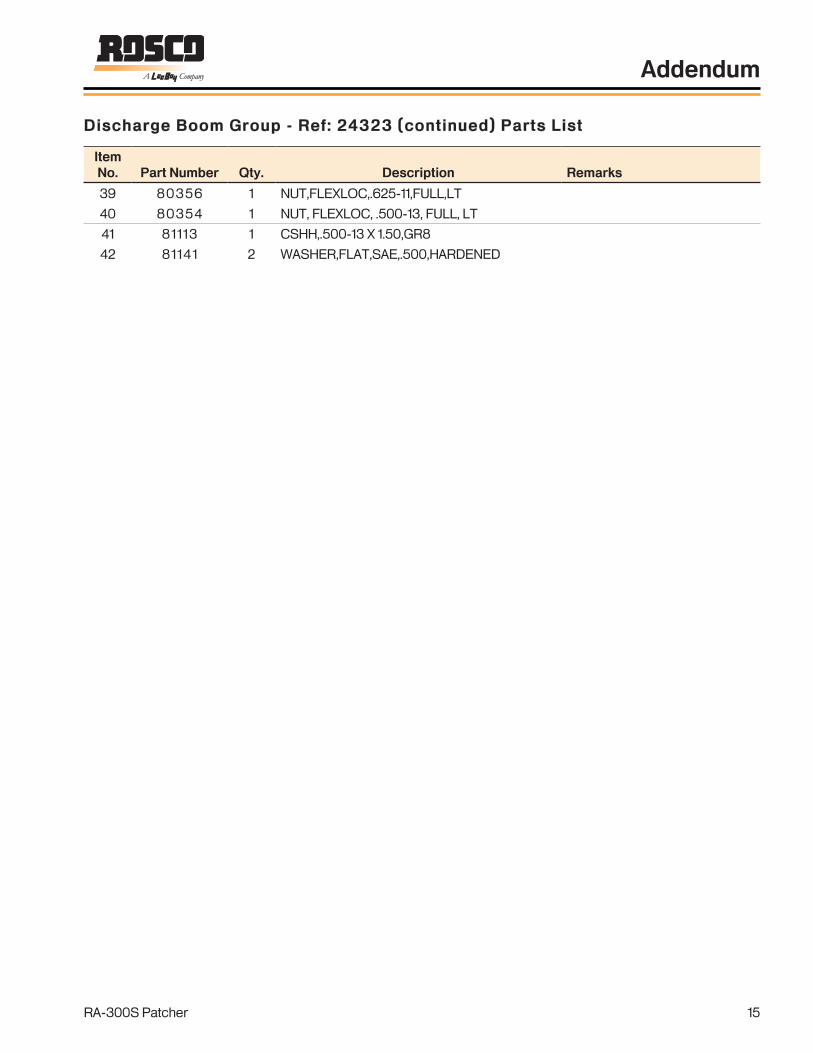
RA-300S Patcher 15
ItemNo. PartNumber Qty. Description Remarks
39 80356 1 NUT,FLEXLOC,.625-11,FULL,LT
40 80354 1 NUT, FLEXLOC, .500-13, FULL, LT
41 81113 1 CSHH,.500-13 X 1.50,GR8
42 81141 2 WASHER,FLAT,SAE,.500,HARDENED
DischargeBoomGroup-Ref:24323(continued)PartsList
Addendum

NOTES
RA-300S Patcher16
Addendum

17
9
Addendum
1002043SK 1 of 312Vdc
+
10A M
M
M
RY6
RY5
RY5
RY6
10A
VIM BOX CONTACT
F2
F3
KEY SWITCH
HM
40A
6.E
30A
4.12
4.2
RY1 16.A
14.A 14.B
16.B
R
R
3.12 6.D 6.F 3.6
9.1
9A.1
9.2
9A.2
4.1
4.11
11.A11.B
3.106.A
3.11 11.A
3.6
6.C15A
PTOSOLENOID
PTOPRESS SW
BEACON
BEACON
BLOWER FAN
BLOWER FAN
GATESW
WATER PUMP
LID OPEN ALARM
LIDPB
15.B 15.B
A CB
BLKRED
RED RED
REDREDRED
YELG/W G/W
YEL
BRN BLU
BLU
BRN
GRN
GRN BLU BLU
BLURED
BRN
BRN BRN
RED
B/R
BRNRED
RED B/R BLUB/R B/R
YEL
YEL
WATER PUMP
MAINPOWER
BEACON
PTOON
ONTRUCK
BLOWER FAN
BLOWER FAN
GATEOPEN
MAINPOWER
30A
30A
5AC1-P02
C1-P01
RA-300S Patcher
Figure 9-30
NOTE: The following replaces 28645SK in RA-300 Patcher Manual.

18
Addendum
RA-300S Patcher
Notes

19
Addendum
RA-300S Patcher
1002043SK 2 of 3A C3.7
3.81.8
1.9
1.510A UP
DOWN
CLOSE
OPEN
SLIDEGATE
BOOMLIFT
UP
DOWN2.5
2.6
1.11
1.10
4.10
4.9
RY3
RY2
10A
RY3
RY2M EMULSION
ACTUATOR
8.B
8.A
3.6
3.6
4.14
4.13
ON
OFF
UP
DOWN
BPRP
YEL
P/YP/Y
PRPPRP
P/Y
B/RB/R
P/Y
PRP
YEL
Y/R
YEL
Y/R
YEL
Y/R
BLK
O/Y
ORN ORN
O/Y
PNKO/YO/Y
BLK
BLK
ORN ORN ORN
BRN/YEL
BRN/YEL
SLIDEGATE OPEN
CLOSELID
EMULSIONON
EMULSIONOFF
EMULSIONON/OFF
EMULSIONCONTROL
BOOMUP/DOWN
D E
BOOMSTOP
Figure 9-30

20
Addendum
RA-300S Patcher
Notes

21
Addendum
RA-300S Patcher
1002043SK 3 of 3
BOOMEXT/RET
OUT
IN
BOOMSWING
RIGHT
LEFT
SLIDEGATEFLOW
MINUS
PLUS
10A 4.62.2
2.1 4.5
2.4 4.8
2.3 4.7
JOYSTICK
MINUS
PLUS
1.7 4.3
1.6 4.4
10A
1.1 3.6RY1
1.3 3.9 12.ABLOWER
SOLENOID 12.B
BLOWOUT
PATCH
1.4
1.12
2.12
5.C
5.B
5.A
3.3
3.2
3.1
+
-13.A
13.B
13.C
AMPLIFLER 5VDCPROP VALVE
10 K
2.7
1.2
BLK GRN GRN
GRN/YELGRN/YEL
R/B R/B R/B
PNKPNKPNK
W/B
BRN
W/B
BRN
W/B
BRN
BLUBLU
WHT WHT
BLK
GRY GRY WHT
BRN
GRNORG/YEL
BRNBRNBRN
O/YGRY
GRY/BLK
BRN/YEL GRY
GRN/YEL G/W
GRY
WHT RED
BOOMOUT
BOOMIN
BOOM SWINGRIGHT
BOOM SWINGLEFT
SLIDEGATEFLOW
BEACON
BLOWERON
BEACON
BLOWERSPEED
D E
CYL SENSOR
C1-P07
C1-P06
C1-P10 BOOM OVERRIDE
C1-P12
C1-P09C1-P11
C1-P08
C1-XXX IS PLUS 1 PIN CONNECTIONS
Figure 9-30

22
Addendum
RA-300S Patcher
Notes

23
Addendum
RA-300S Patcher
1002043 1 of 4
Part No.Item QtyParts list
Description
PLUG #3
17
B A
17
16 14
4
965
(2)24
17
B AC B A
26
13 22
11
25
B A
B A
6 8 9
9
RED BLK
- +
BLU
65
PLUG #4
16
7
30 A
14
2
10
B A
17
16
27
16 A
PLUG #2
1
PLUG #1
18
PLUG #5
3
F E D C B A
F E D C B A
14
F E D C B A
PLUG #6
15
21
12
31 1 29492 1.00 WIRING,RELAYS & FUSE GRP 2 28662 1.00 HARNESS,MAIN,RA300 3 28663 1.00 GAUGE PANEL GRP,GMC,RA300 4 36218 3.00 FUSE,BLADE,30AMP,ATC-30 5 35139 2.00 CONNECTOR,SEALED,TOWER,2-PIN 6 36165 7.00 TERM,SEALED CONN,16-14 GA,FEM 7 34853 1.00 CIRCUIT BREAKER,40 AMP 8 36300 1.00 CONNECTOR,SEALED,TOWER,3-PIN 9 36623 7.00 SEAL,CABLE,14 GA 10 36674 2.00 SOLENOID,CONT DUTY,12V 11 25247 1.00 SWITCH,PUSH BTN,ON-MOM OFF,MOD 12 37688 1.00 TERM,PUSH-ON,.25,FUSE TAP-IN 13 36252 1.00 SWITCH,TOGGLE,SPDT,3-POS,MOM 14 80036 6.00 NUT,HEX,.250-20 15 80140 3.00 WASHER,TYPE A PLAIN,.250 16 80160 8.00 WASHER,SPLIT LOCK,.250 17 80185 8.00 CSHH,.250-20X1.00,GR5 18 80476 3.00 WASHER,SPLIT LOCK,M6 19 80798 2.00 MACH SCR,PH,#10-24X1.00 20 80824 2.00 NUT,HEX,#10-24 21 81182 3.00 MACH SCR,PH,M6X1.0X30,CL8.8 22 871066120 1.00 SEAL,SWITCH,NUT,.469-32 23 871071601 2.00 WASHER,SPLIT LOCK,#10 24 80142 2.00 WASHER,TYPE A PLAIN,.375 25 33312 1.00 CLAMP,MUFFLER,2.5 26 33964 1.00 SWITCH,BACKUP ALARM 27 25650 1.00 COVER,SOLENOIDS 28 37118 3.00 FUSE HOLDER,IN-LINE,BLADE,SEAL 30 36340 1.00 FUSE,BLADE,10AMP,ATC-10 31 25682 1.00 JOYSTICK CONSOLE GRP,RA300 32 1001485 1.00 CONTROLLER,PLUS 1,MC012 33 1000386 1.00 HARNESS,CYL CABLE,20 FT,90 34 851090624 1.00 SWITCH,TOGGLE,SPDT,2-POS 35 988900 1.00 CONN,12-PIN,PLUG,DTM06-12SA 36 988987 12.00 TERM,SOC,DEUTSCH,DRC26 37 73192-02 3.00 CONN,PLUG,16GA WIRE 38 989467-01 .00 CONN,WEDGE,WM-12S 39 983200 1.00 CONN,03-PIN,SOC,DT04-3P 40 983201 1.00 CONN,03-PIN,PLUG,DT06-3S 41 982448 3.00 TERM,SOC,DEUTSCH,14-16AWG 42 983211 1.00 CONN,WEDGE,RECP,3P,DEUTSCH 43 1001485 1.00 CONTROLLER,PLUS 1 44 72086 1.00 SWITCH,TOGGLE,DPDT,2-POS 45 1000386 1.00 HARNESS,CYL CABLE,20FT,90
MOUNT TO PLATEUNDER OIL COOLER
ON FRONT BUMPBER
YEL BOOM UP/DOWN
RED/BLK SWING LEFT/RIGHT
WATER PUMP
WATER PUMP
TIE-UP WIRESOPITION
BEACONWIRES
BEACONREAR
CONNECT PURPLE WIRE TO TOPTERMINAL AND PURPLE/WHITEWIRE TO BOTTOM TERMINAL
PROPVALVE
MOUNT TO SLIDE GATE CYLINDER SO THE CLAMP ACTUATES THE SWITCH WHENTHE GATE IS IN THE CLOSED POSITION
MOUNT TO CROSSMEMBER UNDER ROCK TANKABOVE THE SLIDE GATE CYLINDER YELLOW WIRE TO COMMON GREEN/WHITE TO NORMALY OPEN
SWITCHSLIDE GATE
LIFT SWITCHHOPPER LID
VALVEBLOWER
SELECTOR
SWITCHVALVE
PINK
BATTERY BOX
SOLENOID SWITCHPRESSURE
BATTERY
BRN
OIL COOLER
PTOHYD PUMP
FANS
GRN/YELPRP/WHT
BOTTOM
BEACONWIRES
EMULSION VALVEBOOM HARNESS
YEL/RED
FRONTBEACON
MANIFOLD VALVEVALVE SOLENOIDS
TOP
WHT/BLK GATE ADJUSTMENT
GRN BOOM IN/OUT
PRP GATE OPEN/CLOSE
INSIDE TRUCK CAB
MOUNT UNDER AND BEHINDPASSENGER SEAT
MOUNT TO SIDE OFTRANMISSION CONTROLCONSOLE
TO TRUCK FUSE PANEL,
HAS POWER ONLYWHEN IGNTION IS ON
TO A CIRCUIT THAT
43
44
44
Figure 9-30
NOTE: The following replaces 28645 in RA-300 Patcher Manual.

24
Addendum
RA-300S Patcher
Notes

25
Addendum
RA-300S Patcher
1002043 2 of 4
2b
RED 16
3674
81
2a
DECR
EASE
BLK/YEL
(1a) R
OCK
1a
(1b) R
OCK
1
INCRE
ASE
2
OFF1b
OFF
BEAC
ON
WHT/BLK 16
2OFF
3
3509
8
BLOWE
R
BRN 16
WHT 16
23
OFF
1
RED 16
3674
8
GRAY
(C TER
M) EM
ULSIO
N ON
BLU/RE
D 16
(D TER
M) EM
ULSIO
N OFF
(G TER
M) GA
TE OP
EN
(F TER
M) GA
TE CL
OSE
(A TER
M) BO
OM UP
(B TER
M) BO
OM DO
WN
(E TERM) COMMON POWER
BLK/Y
EL 16
BOOM
RETR
ACK
GRN/YEL 16
ORN/Y
EL 16
ORN 1
6OFF
PRP 1
6OFF
PRP/W
HT 16
BOOM
EXTEN
T
BLU 18
GRN 16
BLK/Y
EL 16
YEL 1
6
YEL/R
ED 16
OFF
SWING
RIGHT
PINK 16
3798
4JO
YSTIC
K
BLK/YEL 16SWING
LEFT
BLK/YEL 16
RED/
BLK 1
6
P2
WHITE
P1
BLU
RED12
OPEN
GRAY
PRP/WHT
BRN
BLU/RED
WHT/BLK
ORN/YEL
ORN
PRP
5
34567678910
891011121112
GRN/YEL
GRN
PINK
RED/BLK
BLK/YEL
YEL/RED
YEL
44
121233
77
5656
88
1212
91011
91011
CONSOLE #29408
Figure 9-30

26
Addendum
RA-300S Patcher
Notes
27
Addendum
RA-300S Patcher
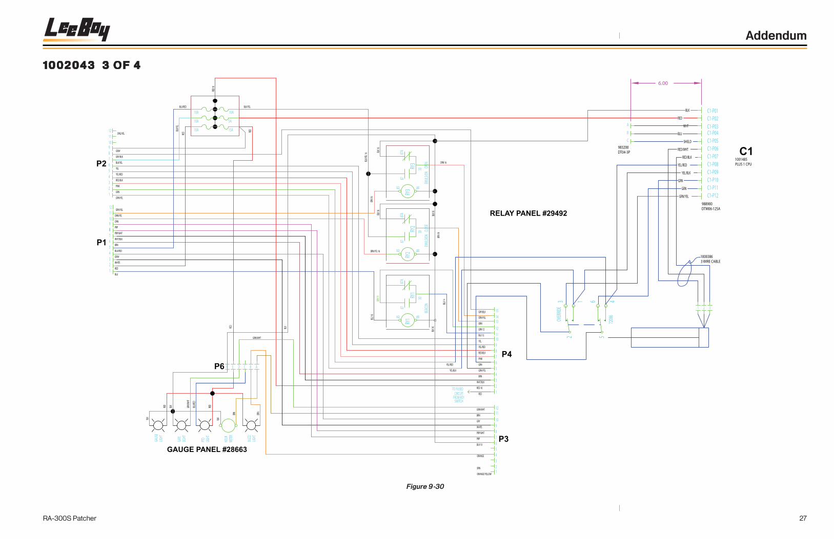
1002043 3 of 4
BLK
BLU
BLK
RED
LIGHT
GAUG
E
P2
P1
7
ORN/YEL
PRP
ORN
GRAY
BRN
RED
WHITE
PRP/WHT
WHT/BLK
BLU/RED
109
67
54321
88
GRN/YEL
YEL
PINK
GRN
GRN/YEL
RED/BLK
BLK/YEL
YEL/RED
65
3
12
1211
4
GRY/BLK
12
91011
8
ORG/YEL
GRN/W
HTLIG
HTGA
TE
BLU/RE
D
PTO
BLK
RED
LIGHT
HOUR
METER
BLK
GRN/WHT
RED
BRN
BLU/RED
REDBL
K/YEL
10A
10A
10A
15A
10A
5A
RED 1
0
RED
BLK/YEL
GRN 1
4
BLU 16 8685
87A
87
RY1
RY1
BLK 1
6
30BE
ACON BLU
14
BRN/YEL 16
BLK/Y
EL 16
ORN 1
6
BLK 1
6BL
K 16
EMUL
SION
OPE
N
8686
87A
8587
RY2
RY2
85
RY3
87RY
3
EMUL
SION
CLO
SE30
BRN 1
4
BLK 1
6
30
ORN 16
87A
RED 10 2
ORANGE/YELLOW
BLK 10
BRN
SWITCHFROM KEY
CIRCUITTO FUSED
RED
GRN/WHT
BRN
GRY
PRP
PRP/WHT
WHITE
654321
P3
1211
9
78
10
1
GRY/BLK
YEL/RED
RED/BLK
GRN/YEL
ORN/YEL
GRN 12
BRN
BLU 12
YEL
PINK
GRN
WHT/BLK
ORN
P4
11
9
678
543
10
1314
12
15
RELAY PANEL #29492
BUZZ
/
ORN
LIGHT
ORANGE
GRAY
P6 C B AE DF
GAUGE PANEL #28663
C1-P05RED/WHT
GRN
SHIELD
YEL/RED
GRN
GRN/YEL
YEL/BLK
RED/BLK
C1-P10C1-P11C1-P12
C1-P06C1-P07
C1-P09C1-P08
RED
BLU
WHT
BLK C1-P01C1-P02C1-P03C1-P04
C1
1 32
YEL/BLK
YEL/RED
10003863 WIRE CABLE
1001485PLUS 1 CPU
988900DTM06-12SA
OVER
RIDE
32
1
B
C
A
983200DT04-3P
6.00
65
7208
64
Figure 9-30

28
Addendum
RA-300S Patcher
Notes

29
Addendum
RA-300S Patcher
1002043 4 of 4
MAIN HARNESS #28662
GATE
POSIT
ION
ORAN
GE/YE
LLOW
PRP/WHT
23
1
4
765
P3
ORANGE/YELLOW
BRN
GRAY
BLK 10
PRP
WHT/B
LK 16
ORN/YEL13121110
89
12
1011
321
987654
P4
BRN
WHITE
BLU/RED
GRN/WHT
BRN 14
WHT/BLK
RED
RED 10
GRN/YEL
YEL/RED
RED/BLK
PINK
GRN
GRN 12
BLU 12
YEL
ORN
1514
FRON
TBE
ACON
P16
GRY/BLK
BA
BLK 1
4
BLU 14
EMUL
SION A
CTUA
TOROP
EN
CLOS
E
RED/
BLK 1
6
YEL 1
6
GRN 1
6
LEFT
RIGHT
BLK 1
6
UP
DOWN BO
OM
OUT
IN
BOOM
BOOM
P8
YEL/R
ED 16
GRN/Y
EL 16
PINK 1
6
PINK
ORN 1
4
ORN/Y
EL ORN
AB
CLOS
E
OPEN
PRP 1
6
MANIFOLD VALVE
BLK 1
6MINU
S
GATE
PLUS
GATE
FRONT VIEW
BRN 1
6
PRP/W
HT 16
30A
GRN 1
2
BLK 1
0(-)
BATT
ERY
C/B #34853
P9
30A
BLUBR
N 14
BLK
BLK 1
4FA
N MOT
ORM
P12
RED
WHITE
B
BLK
BLK
BCA
GRAY
BROW
N
SOLEN
OIDBLO
WER
BLU/RE
D
BLK 1
4
BRN 1
4
BC A
P11
GRN/W
HT
YEL
RED 10
BLK
RED 8
40A
RY5
RED
(+)
RED 1
0
RY6
YEL
ALAR
MBA
CKUP
37624
BEAC
ON
BLU 12
AP13
BLK 1
4
P14
AB
REAR
LID CO
NTRO
L
UP
SWI
TCH
PRP/W
HTPRP
DOWN
OFF
BA
YEL
YEL YE
L BLK 1
6
P15
#367
30
RED
YEL
10A
SWITC
H #00
0200
190
BLK
WATER
PUMP
RED
MRE
D
ORN 16
TEMP SWCLOSES205°F
ORANGE
ADD JUMPER TOBROWN & BLU/RED
989819
Figure 9-30

30
Addendum
RA-300S Patcher
Notes


www.leeboy.com
Printed in the U.S.A.
500 Lincoln County Parkway Ext.
Lincolnton, North Carolina 28092
Phone: (704) 966-3300 - Fax Sales: (704) 483-5802