Embed Size (px)
Citation preview
Buried Distribution Products
DRLS/DCQF Pad-Mount Cross-Connect Cabinet with 50-Pair Terminal Blocks
Description and Installation Manual (631-201-023), Revision G Part Number: P68640
Vertiv | DRLS/DCQF Pad-Mount Cross-Connect Cabinet with 50-Pair Terminal Blocks (631-201-023) | Rev. G 2
The information contained in this document is subject to change without notice and may not be suitable for all applications. While every precaution has been taken to ensure the accuracy and completeness of this document, Vertiv Group Corporation assumes no responsibility and disclaims all liability for damages resulting from use of this information or for any errors or omissions. Refer to other local practices or building codes as applicable for the correct methods, tools, and materials to be used in performing procedures not specifically described in this document.
This document may contain confidential and/or proprietary information of Vertiv Group Corporation, and its receipt or possession does not convey any right to reproduce, disclose its contents, or to manufacture or sell anything that it may describe. Reproduction, disclosure, or use without specific authorization from Vertiv Group Corporation is strictly prohibited.
Vertiv and the Vertiv logo are trademarks or registered trademarks of Vertiv Group Corporation. NetPerform™, NetReach™, NetSure™ and NetXtend™ are trademarks of Vertiv Energy Systems, Inc. All other trademarks are the property of their respective owners.
© 2017 Vertiv Energy Systems, Inc. All rights reserved.
Vertiv | DRLS/DCQF Pad-Mount Cross-Connect Cabinet with 50-Pair Terminal Blocks (631-201-023) | Rev. G 3
TABLE OF CONTENTS Admonishments Used in this Document ............................................................ 5 Important Safety Instructions .............................................................................. 6
Safety Precautions Definition .................................................................................................................... 6 General Safety Precautions ......................................................................................................................... 6 Voltages ........................................................................................................................................................................... 7
AC Input Voltages ........................................................................................................................................................ 7 DC Output and Battery Voltages .................................................................................................................. 7
Specific Safety Precautions ........................................................................................................................ 8 Personal Protective Equipment (PPE) ............................................................................................ 11 Hazardous Voltage ............................................................................................................................................. 11 Handling Equipment Containing Static Sensitive Components............................ 11 Maintenance and Replacement Procedures ............................................................................. 11
Static Warning ......................................................................................................... 12 About this Document ............................................................................................ 13
Purpose ......................................................................................................................................................................... 13 Reason for Reissue ............................................................................................................................................ 13 For Additional Information .......................................................................................................................... 13
Description ............................................................................................................... 14 Overview ....................................................................................................................................................................... 14 Construction ............................................................................................................................................................. 14 Cabinet Models Available ............................................................................................................................ 14 Terminal Blocks ..................................................................................................................................................... 15 Terminal Block Panels .................................................................................................................................... 16 Doors ................................................................................................................................................................................ 17
Installation ................................................................................................................ 18 Site Selection and Preparation .............................................................................................................. 18
Site Selection Considerations .........................................................................................................................18 The Pad ................................................................................................................................................................................18
Transportation and Storage ..................................................................................................................... 19 Mounting the Cabinet ..................................................................................................................................... 19
You Will Need ................................................................................................................................................................ 19 Preparing the Cabinet ........................................................................................................................................... 19 Lifting and Placing the Cabinet ................................................................................................................... 29 Reassembling the Cabinet ................................................................................................................................ 33
Cable Installation and Splicing .......................................................................... 39 Cable Preparation .............................................................................................................................................. 39
You Will Need ................................................................................................................................................................39 Procedure ..........................................................................................................................................................................39
Splicing......................................................................................................................................................................... 40 You Will Need ............................................................................................................................................................... 40
Jumper Wiring ........................................................................................................ 43
Vertiv | DRLS/DCQF Pad-Mount Cross-Connect Cabinet with 50-Pair Terminal Blocks (631-201-023) | Rev. G 4
Overview ...................................................................................................................................................................... 43 CQF Terminal Blocks ...................................................................................................................................... 44 RLS50 Terminal Blocks ................................................................................................................................ 46
Normal Wire Termination on An RLS50 Block ............................................................................. 46 Dual Wire Termination on An RLS50 Block .................................................................................... 46
Ordering Information ............................................................................................ 47
Vertiv | DRLS/DCQF Pad-Mount Cross-Connect Cabinet with 50-Pair Terminal Blocks (631-201-023) | Rev. G 5
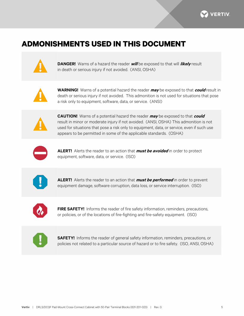
ADMONISHMENTS USED IN THIS DOCUMENT
DANGER! Warns of a hazard the reader will be exposed to that will likely result in death or serious injury if not avoided. (ANSI, OSHA)
WARNING! Warns of a potential hazard the reader may be exposed to that could result in death or serious injury if not avoided. This admonition is not used for situations that pose a risk only to equipment, software, data, or service. (ANSI)
CAUTION! Warns of a potential hazard the reader may be exposed to that could result in minor or moderate injury if not avoided. (ANSI, OSHA) This admonition is not used for situations that pose a risk only to equipment, data, or service, even if such use appears to be permitted in some of the applicable standards. (OSHA)
ALERT! Alerts the reader to an action that must be avoided in order to protect equipment, software, data, or service. (ISO)
ALERT! Alerts the reader to an action that must be performed in order to prevent equipment damage, software corruption, data loss, or service interruption. (ISO)
FIRE SAFETY! Informs the reader of fire safety information, reminders, precautions, or policies, or of the locations of fire-fighting and fire-safety equipment. (ISO)
SAFETY! Informs the reader of general safety information, reminders, precautions, or policies not related to a particular source of hazard or to fire safety. (ISO, ANSI, OSHA)
Vertiv | DRLS/DCQF Pad-Mount Cross-Connect Cabinet with 50-Pair Terminal Blocks (631-201-023) | Rev. G 6
IMPORTANT SAFETY INSTRUCTIONS Safety Precautions Definition Definitions of the safety admonishments used in this document are listed under “Admonishments Used in this Document” on page 5.
General Safety Precautions The following precautions shall be observed at all time when handling and installing the enclosure:
• Observe the general safety precautions against personal injury and equipment damage.
• The procedures outlined in this manual are only recommended guidelines. Ensure that all NEC (National Electric Code) and local codes for safety and wiring are followed.
- Use listed two-hole compression connectors (lugs) to terminate all ground connections. Selected lug shall match wire and type, and crimped applied as specified by the lug manufacturer.
- Apply NO-OX-ID-A to all ground connections. - Insulation of field-wire conductors should be rated no less than 105 °C, and gauge in a manner that
is consistent with the NEC and local codes.
• Always use a non-contact voltage detector, when approaching an enclosure, to verify no leaks or shorts are presents on the external body.
• Read Enclosure Placement in its entirety prior to attempting to handle or secure the enclosure.
• A minimum of two persons are required to safely install the enclosure.
• Hard hats and steel-toed boots should be worn while maneuvering the enclosure.
• Safety glasses should always be on while on-site.
• Safety gloves should be on when working in temperature extremes, with batteries, or with sharp objects.
• All electricians, operators, and technicians have been trained for the task at hand.
• Keep bystanders away.
• Ensure that all personnel on site are familiar with the first-aid kit location and emergency procedures in the event of an injury.
• Never leave the enclosure unattended. If leaving the site, close and secure the enclosure.
Vertiv | DRLS/DCQF Pad-Mount Cross-Connect Cabinet with 50-Pair Terminal Blocks (631-201-023) | Rev. G 7
You Must Follow Approved Safety Procedures
DANGER! Performing the following procedures may expose you to hazards. These procedures should be performed by qualified technicians familiar with the hazards associated with this type of equipment. These hazards may include shock, energy, and/or burns. To avoid these hazards:
a) The tasks should be performed in the order indicated.
b) Remove watches, rings, and other metal objects.
c) Prior to contacting any uninsulated surface or termination, use a voltmeter to verify that no voltage or the expected voltage is present. Check for voltage with both AC and DC voltmeters prior to making contact.
d) Wear eye protection.
e) Use certified and well maintained insulated tools. Use double insulated tools appropriately rated for the work to be performed.
Voltages AC Input Voltages
DANGER! This system operates from AC input voltage capable of producing fatal electrical shock. AC input power must be completely disconnected from the branch circuits wiring used to provide power to the system before any AC electrical connections are made. Follow local lockout/tagout procedures to ensure upstream branch circuit breakers remain de-energized during installation. DO NOT apply AC input power to the system until all electrical connections have been completed and checked.
DC Output and Battery Voltages
DANGER! This system produces DC power and may have a battery source connected to it. Although the DC voltage is not hazardously high, the rectifiers and/or battery can deliver large amounts of current. Exercise extreme caution not to inadvertently contact or have any tool inadvertently contact an output terminal or battery terminal or exposed wire connected to an output terminal or battery terminal. NEVER allow a metal object, such as a tool, to contact more than one termination or battery terminal at a time, or to simultaneously contact a termination or battery terminal and a grounded object. Even a momentary short circuit can cause sparking, explosion, and injury.
Vertiv | DRLS/DCQF Pad-Mount Cross-Connect Cabinet with 50-Pair Terminal Blocks (631-201-023) | Rev. G 8
Specific Safety Precautions DANGER! RISK OF ELECTRICAL SHOCK, GENERAL
All ground connections must be installed and verified prior to connecting any power cables (AC or DC) and turning-up of enclosure.
When connecting any discrete power connection, make the connection first with the ground/return and break last with ground/return.
Do not install equipment showing any physical damage.
DANGER! RISK OF ELECTRICAL SHOCK, AC Proper actions, include, but not limited to:
a) Verify before contacting the enclosure that no current leakage or ground fault condition is present.
b) Verify a proper ground is in place.
c) Verify for AC hook-up, all enclosure circuit breakers are OFF and the utility incoming feed is OFF.
Use a trained licensed electrician.
DANGER! RISK OF ELECTRIC SHOCK The DC bus is powered by DUAL power sources – Rectifiers and DC Batteries.
To properly work on the system, de-energize by disconnecting BOTH power sources. Even with the batteries turned off by using a local battery (circuit breaker) disconnect, batteries are still “LIVE” and hazardous, including a voltage >50 VDC, and a source of high short circuit current.
Use extreme caution around the batteries and terminals.
Do not smoke.
DANGER! RISK OF ELECTRICAL SHOCK, OSP CABLES If joint buried cables are used, check the cable sheath for voltage in accordance with local standards. If voltage is detected, do not proceed with the installation. Contact the supervisor and do not proceed until the voltage hazard is eliminated.
DANGER! RISK OF CHEMICAL EXPOSURE A battery can present harmful chemicals. Refer to the Battery Installation Manuals and MSDS supplied with the batteries. Work in a ventilated area and follow all safety procedures.
At a minimum, wear safety glasses and gloves when working with batteries.
Vertiv | DRLS/DCQF Pad-Mount Cross-Connect Cabinet with 50-Pair Terminal Blocks (631-201-023) | Rev. G 9
WARNING! PREVENT INJURIES, FROM LIFTING THE ENCLOSURE Follow all local safety practices while lifting the enclosure. Wear all locally approved safety gear. All persons working with lifting equipment must wear standard safety headgear, eye protection, and (when required) gloves.
Keep bystanders away from work operations at all times.
Do not lift the enclosure over people. Do not let anyone work, stand, or pass under a lifted enclosure.
Use all four points (eyebolts) to lift the enclosure.
Do not move or lift the enclosure with the front door open.
Never lift or move the enclosure with batteries or rectifiers installed.
Do not allow the lifting equipment or enclosure to touch any electrical wiring or equipment.
Operate all lifting equipment within safety constraints, as defined by the manufacturer and local practices; for example, do not exceed the capacity of reach.
Do not use slings, clevises or shackles of insufficient capacity.
Crane Operation:
Only properly trained operators shall operate the crane.
Do not operate the crane until all stabilizers are extended. The stabilizers must be in firm contact with the ground or other adequate support structure. Do not retract or extend the stabilizers when the enclosure is suspended from the crane.
Do not lift the enclosure over people. Do not let anyone work, stand, or pass under a lifted enclosure.
Only the crane rigging crew should set up the crane and rigging.
Do not exceed the lifting capacity of the crane.
Forklift Operation:
The forklift must be rated for a lifting capacity of 4,000 lbs (1814 kg), or greater.
Required Equipment:
One hoist, crane, or forklift capable of lifting 4,000 lbs (1814 kg).
Four wire-rope slings, 8-ft. (2.44 m) long (minimum). Each sling should have 1,500 lb. (700 kg) capacity.
Four connecting links (clevises) (rated for a minimum of 1500 lb), to attach the wire-rope slings to the enclosure lifting eyes.
A 75-ft (20 m) rope, 5/8” (1.5 cm) in diameter, to use as a tagline. A tagline is used to guide the enclosure into position while it is lifted and lowered.
Vertiv | DRLS/DCQF Pad-Mount Cross-Connect Cabinet with 50-Pair Terminal Blocks (631-201-023) | Rev. G 10
CAUTION! PREVENT EQUIPMENT DAMAGE, PROPER HANDLING Do not stack nor lay the enclosure on its side.
Similarly, do not stack batteries or lay them on their side. Do not tip batteries -- keep in upright position at all times.
To avoid possible personnel injury or damage to the enclosure, do not remove it from the pallet until at the installation site, at the point of transfer onto the pad.
DANGER! PREVENT EQUIPMENT DAMAGE, MAINTAIN VENTILATION To optimize the service life of this equipment, make sure there are no obstructions in front of the ventilation openings.
WARNING! RISK OF INJURY, FROM UNSECURED ENCLOSURE Do not push or lean against an unsecured (unbolted) enclosure as it may tip over causing bodily injury.
Do not pull cables, terminate cables, install or place any batteries or rectifiers until enclosure has been secured onto a pad.
Use caution when opening and closing doors to an enclosure not secured onto a pad.
WARNING! RISK OF INJURY TO EYES AND SKIN, FROM OPTIC DEVICES Do not look into a fiber cable or device, nor hold such cable or device against body, fabric or other material.
WARNING! RISK OF HAZARDOUS SUBSTANCES After handling of the enclosure or any such component, such as batteries, cables, busbars, etc., always wash hands immediately after.
WARNING! RISK OF EXPLOSION For safety reasons, never restrict or block the airflow through the door or entry panel ventilation openings.
CAUTION! PREVENT EQUIPMENT DAMAGE, FROM CONDENSATION Until the enclosure is turned up for service, the bags of desiccant shipped with the enclosure must remain in the enclosure to prevent condensation.
Once service is in-place, remove the desiccant.
CAUTION! PREVENT EQUIPMENT DAMAGE, BUILD A GOOD PAD The pad should be level to within 1/4 in (6.4 mm) over the entire length and width, with a crown in the middle to prevent any pooling of water and twist to the enclosure frame.
When mounting the enclosure on a pad, the compression strength of the concrete pad used must be a minimum of 4000 psi as determined by ASTM C39 test of compression strength of concrete cylinders.
Always use a barrier pad between the concrete and the pad to prevent corrosion.
Vertiv | DRLS/DCQF Pad-Mount Cross-Connect Cabinet with 50-Pair Terminal Blocks (631-201-023) | Rev. G 11
CAUTION! PREVENT EQUIPMENT DAMAGE, OPERATING TEMPERATURE The enclosure is approved for operation in an environment with an expected temperature range of -40°F to +115°F (–40° C to +46°C) and 5% to 95% relative humidity range, condensing. Do not use at temperatures or humidity exceeding these ranges.
The enclosure is not for indoor use.
CAUTION! PREVENT DAMAGES CAUSED BY ELECTROSTATIC DISCHARGES (ESD) When handling the ECU unit, wear an appropriate antistatic device (a wrist strap for example) that is properly connected to a designated antistatic grounding point (on a framework, on an anti-static floor mat, etc.). ESD-protective packaging material shall also be used when carrying/shipping the ECU unit.
Personal Protective Equipment (PPE) DANGER! ARC FLASH AND SHOCK HAZARD.
Appropriate PPE and tools required when working on this equipment. An appropriate flash protection boundary analysis should be done determine the “hazard/risk” category, and to select proper PPE.
Only authorized and properly trained personnel should be allowed to install, inspect, operate, or maintain the equipment.
Do not work on LIVE parts. If required to work or operate live parts, obtain appropriate Energized Work Permits as required by the local authority, per NFPA 70E “Standard for Electrical Safety in the Workplace”.
Hazardous Voltage DANGER! HAZARD OF ELECTRICAL SHOCK.
More than one disconnect may be required to de-energize the system before servicing.
Handling Equipment Containing Static Sensitive Components ALERT! Installation or removal of equipment containing static sensitive components requires careful
handling. Before handling any equipment containing static sensitive components, read and follow the instructions contained on the Static Warning Page.
Maintenance and Replacement Procedures CAUTION! When performing any step in procedures that requires removal or installation of hardware,
use caution to ensure no hardware is dropped and left inside the unit; otherwise service interruption or equipment damage may occur.
NOTE! When performing any step in procedures that requires removal of existing hardware, retain all hardware for use in subsequent steps, unless otherwise directed.
Vertiv | DRLS/DCQF Pad-Mount Cross-Connect Cabinet with 50-Pair Terminal Blocks (631-201-023) | Rev. G 12
STATIC WARNING This equipment contains static sensitive components. The warnings listed below must be observed to
prevent damage to these components. Disregarding any of these warnings may result in personal injury or damage to the equipment.
1. Strictly adhere to the procedures provided in this document.
2. Before touching any equipment containing static sensitive components, discharge all static electricity from yourself by wearing a wrist strap grounded through a one megohm resistor. Some wrist straps have a built-in one megohm resistor; no external resistor is necessary. Read and follow wrist strap manufacturer’s instructions outlining use of a specific wrist strap.
3. Do not touch traces or components on equipment containing static sensitive components. Handle equipment containing static sensitive components only by the edges that do not have connector pads.
4. After removing equipment containing static sensitive components, place the equipment only on conductive or anti-static material such as conductive foam, conductive plastic, or aluminum foil. Do not use ordinary Styrofoam™ or ordinary plastic.
5. Store and ship equipment containing static sensitive components only in static shielding containers.
6. If necessary to repair equipment containing static sensitive components, wear an appropriately grounded wrist strap, work on a conductive surface, use a grounded soldering iron, and use grounded test equipment.
Vertiv | DRLS/DCQF Pad-Mount Cross-Connect Cabinet with 50-Pair Terminal Blocks (631-201-023) | Rev. G 13
ABOUT THIS DOCUMENT Purpose This practice provides a description of the UltraCab Cross-Connect drop-down style center-feed cabinet equipped with RLS or CQF terminal blocks as well as installation instructions.
Reason for Reissue This practice has been reissued to include information on the new cabinet design.
For Additional Information Refer to other company and local practices for the correct methods, tools, and materials to be used in performing procedures not specifically described within this practice. Refer to the following documents for specific information on wire terminations on RLS50 blocks and on mounting templates:
• 641-202-002, RS50 Self-Strip Block Description and Installation,
• 641-202-009, RS50 Self-Strip Block Feed-Thru Half-Tap Activator Kit Description and Installation, and
• 644-200-010, Metal Mounting Templates Description and Installation.
NOTE! The information in this practice is subject to change without notice and may not be suitable in all situations.
Vertiv | DRLS/DCQF Pad-Mount Cross-Connect Cabinet with 50-Pair Terminal Blocks (631-201-023) | Rev. G 14
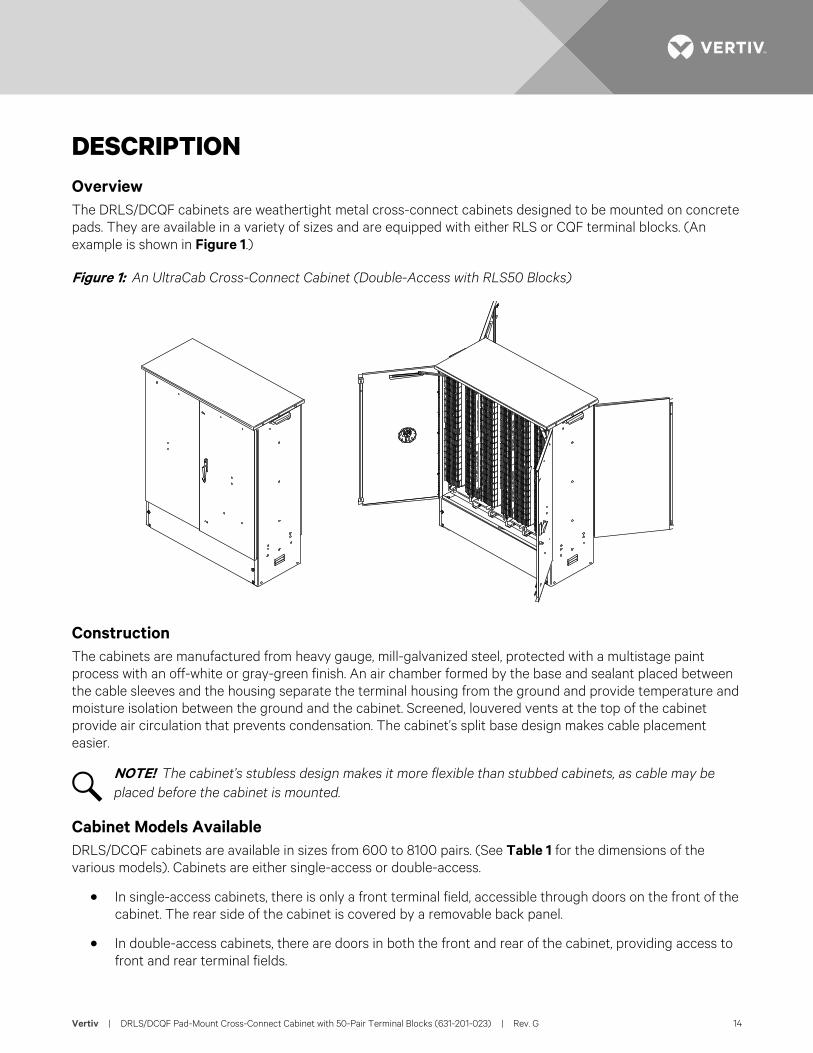
DESCRIPTION Overview The DRLS/DCQF cabinets are weathertight metal cross-connect cabinets designed to be mounted on concrete pads. They are available in a variety of sizes and are equipped with either RLS or CQF terminal blocks. (An example is shown in Figure 1.)
Figure 1: An UltraCab Cross-Connect Cabinet (Double-Access with RLS50 Blocks)
Construction The cabinets are manufactured from heavy gauge, mill-galvanized steel, protected with a multistage paint process with an off-white or gray-green finish. An air chamber formed by the base and sealant placed between the cable sleeves and the housing separate the terminal housing from the ground and provide temperature and moisture isolation between the ground and the cabinet. Screened, louvered vents at the top of the cabinet provide air circulation that prevents condensation. The cabinet’s split base design makes cable placement easier.
NOTE! The cabinet’s stubless design makes it more flexible than stubbed cabinets, as cable may be placed before the cabinet is mounted.
Cabinet Models Available DRLS/DCQF cabinets are available in sizes from 600 to 8100 pairs. (See Table 1 for the dimensions of the various models). Cabinets are either single-access or double-access.
• In single-access cabinets, there is only a front terminal field, accessible through doors on the front of the cabinet. The rear side of the cabinet is covered by a removable back panel.
• In double-access cabinets, there are doors in both the front and rear of the cabinet, providing access to front and rear terminal fields.
Vertiv | DRLS/DCQF Pad-Mount Cross-Connect Cabinet with 50-Pair Terminal Blocks (631-201-023) | Rev. G 15
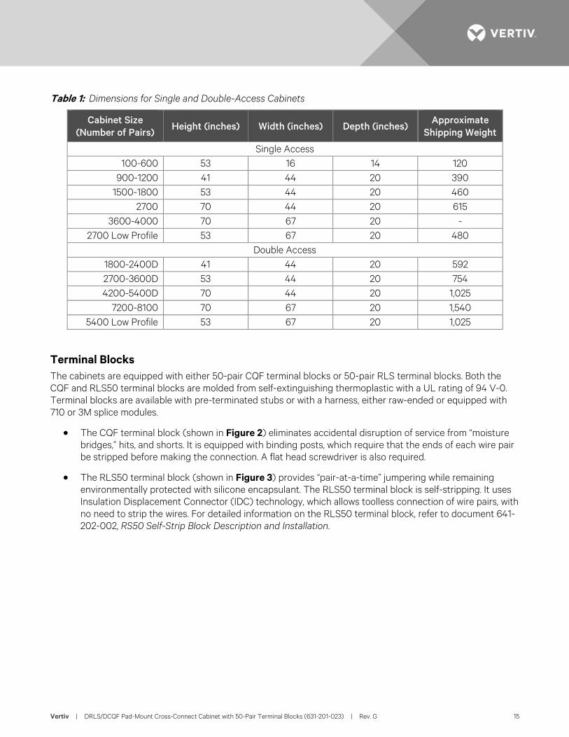
Table 1: Dimensions for Single and Double-Access Cabinets
Cabinet Size (Number of Pairs) Height (inches) Width (inches) Depth (inches)
Approximate Shipping Weight
Single Access 100-600 53 16 14 120
900-1200 41 44 20 390 1500-1800 53 44 20 460
2700 70 44 20 615 3600-4000 70 67 20 -
2700 Low Profile 53 67 20 480 Double Access
1800-2400D 41 44 20 592 2700-3600D 53 44 20 754 4200-5400D 70 44 20 1,025
7200-8100 70 67 20 1,540 5400 Low Profile 53 67 20 1,025
Terminal Blocks The cabinets are equipped with either 50-pair CQF terminal blocks or 50-pair RLS terminal blocks. Both the CQF and RLS50 terminal blocks are molded from self-extinguishing thermoplastic with a UL rating of 94 V-0. Terminal blocks are available with pre-terminated stubs or with a harness, either raw-ended or equipped with 710 or 3M splice modules.
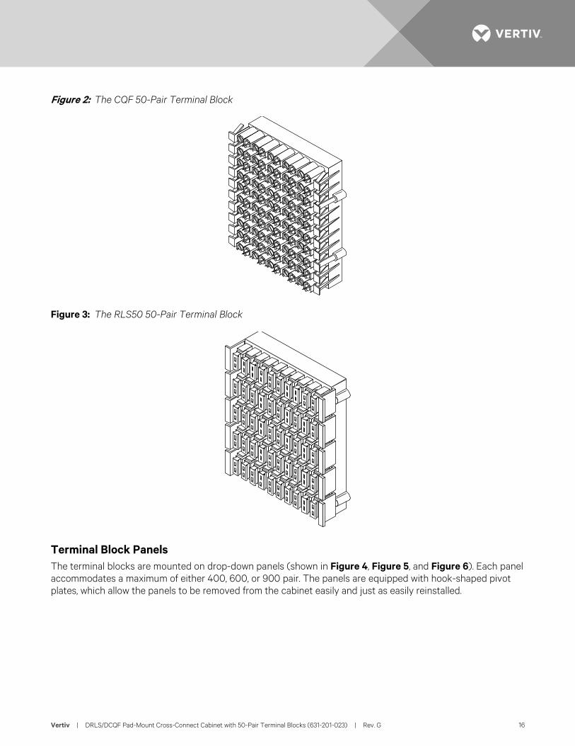
• The CQF terminal block (shown in Figure 2) eliminates accidental disruption of service from “moisture bridges,” hits, and shorts. It is equipped with binding posts, which require that the ends of each wire pair be stripped before making the connection. A flat head screwdriver is also required.
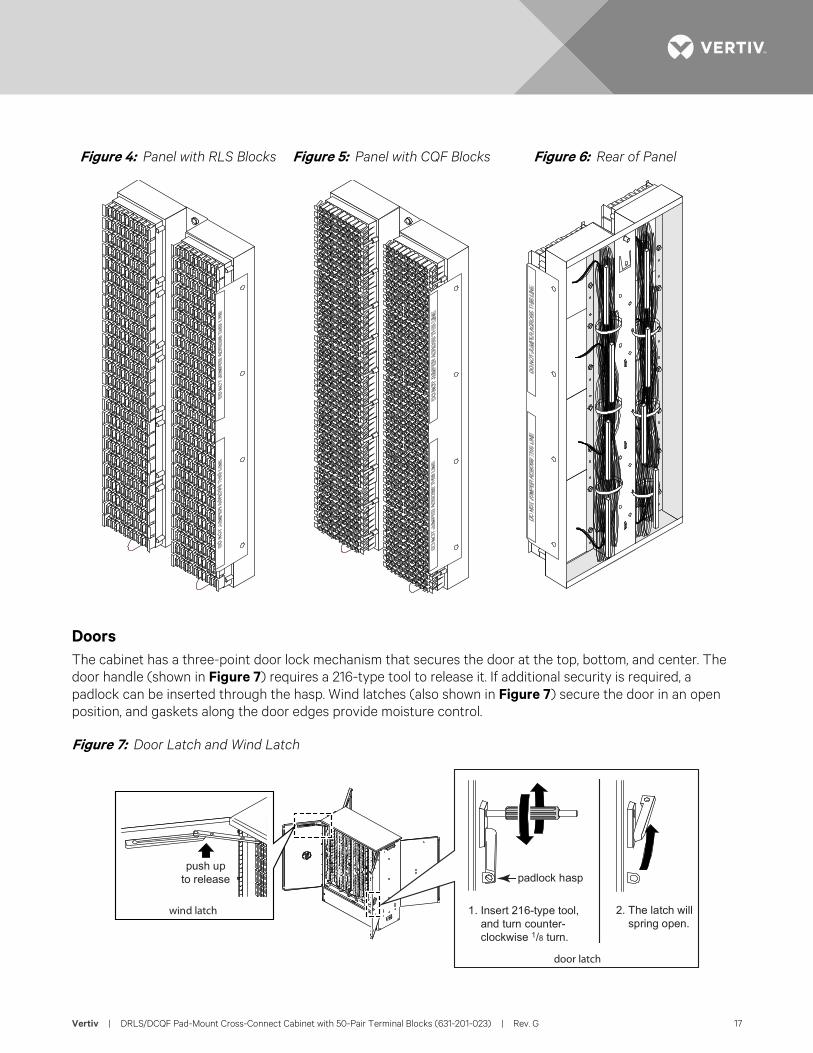
• The RLS50 terminal block (shown in Figure 3) provides “pair-at-a-time” jumpering while remaining environmentally protected with silicone encapsulant. The RLS50 terminal block is self-stripping. It uses Insulation Displacement Connector (IDC) technology, which allows toolless connection of wire pairs, with no need to strip the wires. For detailed information on the RLS50 terminal block, refer to document 641-202-002, RS50 Self-Strip Block Description and Installation.
Vertiv | DRLS/DCQF Pad-Mount Cross-Connect Cabinet with 50-Pair Terminal Blocks (631-201-023) | Rev. G 16
Figure 2: The CQF 50-Pair Terminal Block
Figure 3: The RLS50 50-Pair Terminal Block
Terminal Block Panels The terminal blocks are mounted on drop-down panels (shown in Figure 4, Figure 5, and Figure 6). Each panel accommodates a maximum of either 400, 600, or 900 pair. The panels are equipped with hook-shaped pivot plates, which allow the panels to be removed from the cabinet easily and just as easily reinstalled.
Vertiv | DRLS/DCQF Pad-Mount Cross-Connect Cabinet with 50-Pair Terminal Blocks (631-201-023) | Rev. G 17
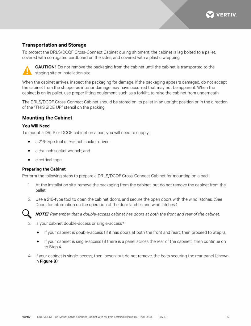
Figure 4: Panel with RLS Blocks
Figure 5: Panel with CQF Blocks
Figure 6: Rear of Panel
Doors The cabinet has a three-point door lock mechanism that secures the door at the top, bottom, and center. The door handle (shown in Figure 7) requires a 216-type tool to release it. If additional security is required, a padlock can be inserted through the hasp. Wind latches (also shown in Figure 7) secure the door in an open position, and gaskets along the door edges provide moisture control.
Figure 7: Door Latch and Wind Latch
1. Insert 216-type tool,and turn counter-clockwise 1/8 turn.
2. The latch willspring open.
push upto release
door latch
wind latch
padlock hasp
Vertiv | DRLS/DCQF Pad-Mount Cross-Connect Cabinet with 50-Pair Terminal Blocks (631-201-023) | Rev. G 18
INSTALLATION Site Selection and Preparation CAUTION! Follow all local safety practices and wear all appropriate safety gear during site preparation
and installation.
Site Selection Considerations Consider the following items when choosing the cabinet location:
• Permanent Location: Planning and hardware use should accommodate at least a 20- to 30-year life.
• Vulnerability: Locations should minimize the probability of damage occurring to the cabinet or equipment. Use protective posts when locating the equipment near parking areas where vehicles may back into the housing. Do not place the cabinet in ditches or areas subject to flooding.
• Accessibility: Place the cabinet at least 36 inches from any obstruction.
• Safety: Use public roads and street rights-of-way only when there is adequate space to place the cabinet and provide safe working conditions. The terminal should be easily accessible with adequate parking to insure craft and vehicle safety. Also, place the terminal where it will not create a visual obstruction to vehicular or pedestrian traffic.
• Acceptability: The location should be acceptable to both the property owner and the general public.
• Locate the cabinet in accordance with detailed plans. If the location seems unsuitable for any reason, consult the engineer.
The Pad A composolite, polyurethane, or concrete pad, which may be precast or poured on site according to local practices, must be provided. An optional Metal Mounting Template, to be embedded flush into the concrete pad, may be purchased separately. (See the practice 644-200-010, Metal Mounting Templates Description and Installation for more specific information on mounting templates.) The site selected must be firm and level to minimize future shifting. Usually local soil conditions determine slab thickness and the amount of reinforcement required. The following specifications should meet normal strength requirements for concrete:
• A four-inch thick slab.
• Reinforcements of 3/8-inch steel rods placed on 12-inch centers along both the length and width of the concrete slabs and secured together.
NOTE! Install the conduit for feeder and distribution cabling prior to pad construction. Conform to local electrical construction standards for conduit materials and sizing.
CAUTION! When using precast concrete foundation pads, the pads should be in place before the cables are installed. This will avoid a safety hazard as it prevents personnel from reaching under a pad as it is lowered to feed cable through the pad openings.
Vertiv | DRLS/DCQF Pad-Mount Cross-Connect Cabinet with 50-Pair Terminal Blocks (631-201-023) | Rev. G 19
Transportation and Storage To protect the DRLS/DCQF Cross-Connect Cabinet during shipment, the cabinet is lag bolted to a pallet, covered with corrugated cardboard on the sides, and covered with a plastic wrapping.
CAUTION! Do not remove the packaging from the cabinet until the cabinet is transported to the staging site or installation site.
When the cabinet arrives, inspect the packaging for damage. If the packaging appears damaged, do not accept the cabinet from the shipper as interior damage may have occurred that may not be apparent. When the cabinet is on its pallet, use proper lifting equipment, such as a forklift, to raise the cabinet from underneath.
The DRLS/DCQF Cross-Connect Cabinet should be stored on its pallet in an upright position or in the direction of the “THIS SIDE UP” stencil on the packing.
Mounting the Cabinet You Will Need To mount a DRLS or DCQF cabinet on a pad, you will need to supply:
• a 216-type tool or 7/16-inch socket driver;
• a 7/16-inch socket wrench; and
• electrical tape.
Preparing the Cabinet Perform the following steps to prepare a DRLS/DCQF Cross-Connect Cabinet for mounting on a pad:
1. At the installation site, remove the packaging from the cabinet, but do not remove the cabinet from the pallet.
2. Use a 216-type tool to open the cabinet doors, and secure the open doors with the wind latches. (See Doors for information on the operation of the door latches and wind latches.)
NOTE! Remember that a double-access cabinet has doors at both the front and rear of the cabinet.
3. Is your cabinet double-access or single-access?
• If your cabinet is double-access (if it has doors at both the front and rear), then proceed to Step 6.
• If your cabinet is single-access (if there is a panel across the rear of the cabinet), then continue on to Step 4.
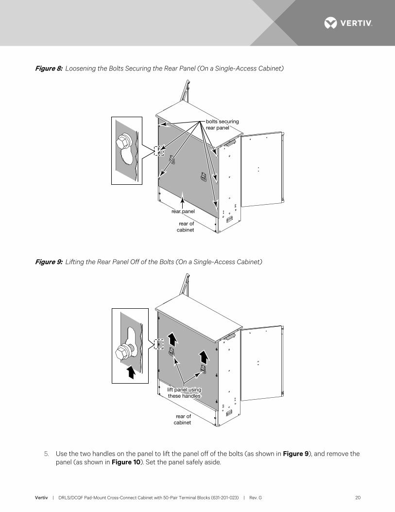
4. If your cabinet is single-access, then loosen, but do not remove, the bolts securing the rear panel (shown in Figure 8).
Vertiv | DRLS/DCQF Pad-Mount Cross-Connect Cabinet with 50-Pair Terminal Blocks (631-201-023) | Rev. G 20
Figure 8: Loosening the Bolts Securing the Rear Panel (On a Single-Access Cabinet)
Figure 9: Lifting the Rear Panel Off of the Bolts (On a Single-Access Cabinet)
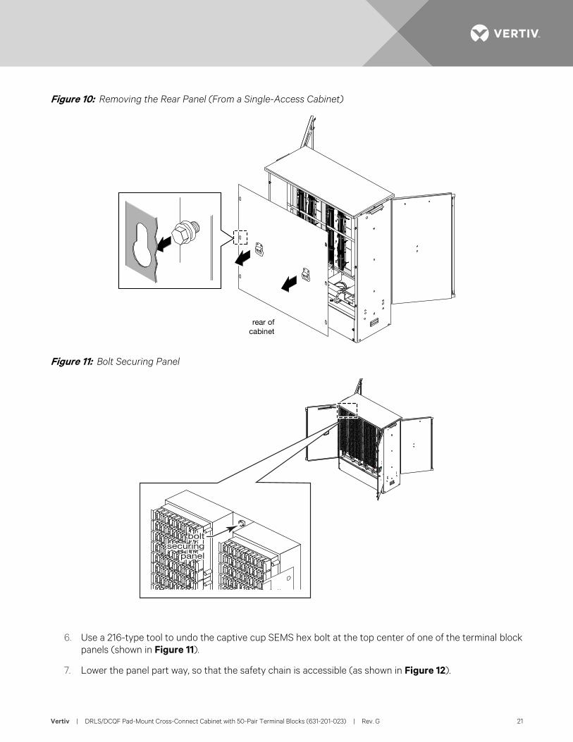
5. Use the two handles on the panel to lift the panel off of the bolts (as shown in Figure 9), and remove the panel (as shown in Figure 10). Set the panel safely aside.
bolts securingrear panel
rear panel
rear ofcabinet
lift panel usingthese handles
rear ofcabinet
Vertiv | DRLS/DCQF Pad-Mount Cross-Connect Cabinet with 50-Pair Terminal Blocks (631-201-023) | Rev. G 21
Figure 10: Removing the Rear Panel (From a Single-Access Cabinet)
Figure 11: Bolt Securing Panel
6. Use a 216-type tool to undo the captive cup SEMS hex bolt at the top center of one of the terminal block panels (shown in Figure 11).
7. Lower the panel part way, so that the safety chain is accessible (as shown in Figure 12).
rear ofcabinet
Vertiv | DRLS/DCQF Pad-Mount Cross-Connect Cabinet with 50-Pair Terminal Blocks (631-201-023) | Rev. G 22
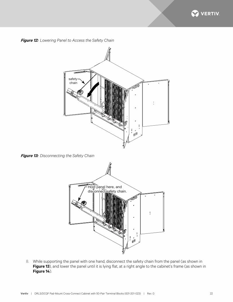
Figure 12: Lowering Panel to Access the Safety Chain
Figure 13: Disconnecting the Safety Chain
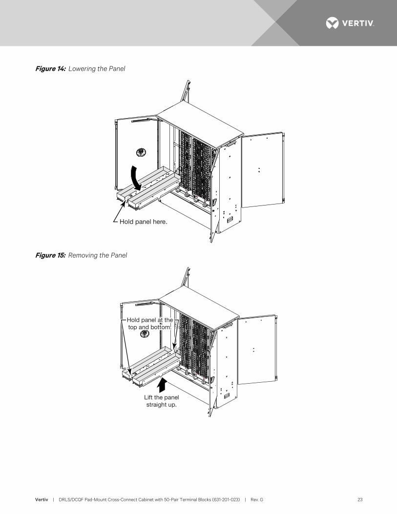
8. While supporting the panel with one hand, disconnect the safety chain from the panel (as shown in Figure 13), and lower the panel until it is lying flat, at a right angle to the cabinet’s frame (as shown in Figure 14).
safetychain
Hold panel here, anddisconnect safety chain.
Vertiv | DRLS/DCQF Pad-Mount Cross-Connect Cabinet with 50-Pair Terminal Blocks (631-201-023) | Rev. G 23
Figure 14: Lowering the Panel
Figure 15: Removing the Panel
Hold panel here.
Lift the panelstraight up.
Hold panel at thetop and bottom.
Vertiv | DRLS/DCQF Pad-Mount Cross-Connect Cabinet with 50-Pair Terminal Blocks (631-201-023) | Rev. G 24
9. Using both hands, lift the panel straight upwards, disengaging the hook-shaped pivot plates at the bottom of the panel from the slots in the cabinet’s frame, and remove the panel. (See Figure 15.) Make note of the position in the cabinet from which the panel was removed, and set the panel safely aside.
10. Set the panel safely aside, on its back with the terminal blocks facing up.
11. Are there terminal block panels remaining in the cabinet?
• If no, then continue on to Step 3.
• If yes, then return to Step 6 to remove another panel from the cabinet.
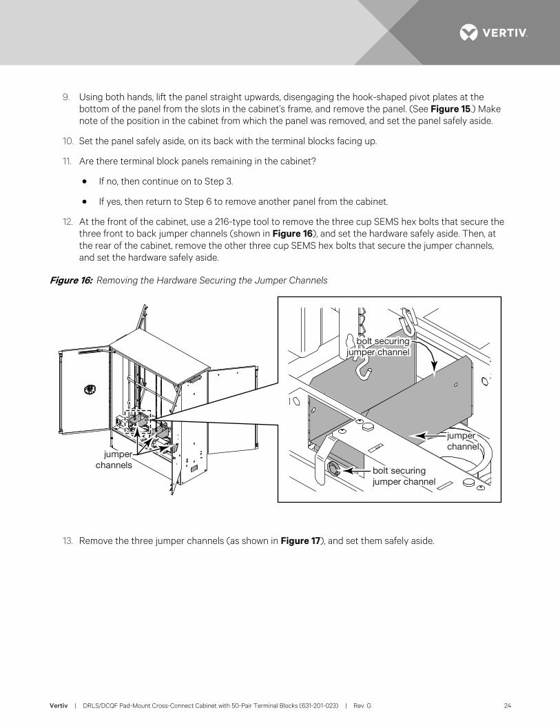
12. At the front of the cabinet, use a 216-type tool to remove the three cup SEMS hex bolts that secure the three front to back jumper channels (shown in Figure 16), and set the hardware safely aside. Then, at the rear of the cabinet, remove the other three cup SEMS hex bolts that secure the jumper channels, and set the hardware safely aside.
Figure 16: Removing the Hardware Securing the Jumper Channels
13. Remove the three jumper channels (as shown in Figure 17), and set them safely aside.
jumperchannels
bolt securingjumper channel
jumperchannel
bolt securingjumper channel
Vertiv | DRLS/DCQF Pad-Mount Cross-Connect Cabinet with 50-Pair Terminal Blocks (631-201-023) | Rev. G 25
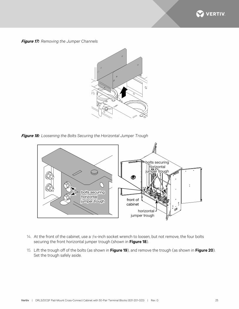
Figure 17: Removing the Jumper Channels
Figure 18: Loosening the Bolts Securing the Horizontal Jumper Trough
14. At the front of the cabinet, use a 7/16-inch socket wrench to loosen, but not remove, the four bolts securing the front horizontal jumper trough (shown in Figure 18).
15. Lift the trough off of the bolts (as shown in Figure 19), and remove the trough (as shown in Figure 20). Set the trough safely aside.
bolts securinghorizontaljumper trough
bolts securinghorizontal
jumper trough
horizontaljumper trough
front ofcabinet
Vertiv | DRLS/DCQF Pad-Mount Cross-Connect Cabinet with 50-Pair Terminal Blocks (631-201-023) | Rev. G 26
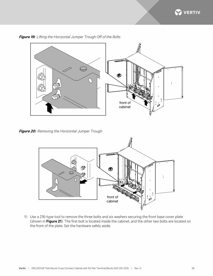
Figure 19: Lifting the Horizontal Jumper Trough Off of the Bolts
Figure 20: Removing the Horizontal Jumper Trough
16. Use a 216-type tool to remove the three bolts and six washers securing the front base cover plate (shown in Figure 21). The first bolt is located inside the cabinet, and the other two bolts are located on the front of the plate. Set the hardware safely aside.
front ofcabinet
front ofcabinet
Vertiv | DRLS/DCQF Pad-Mount Cross-Connect Cabinet with 50-Pair Terminal Blocks (631-201-023) | Rev. G 27
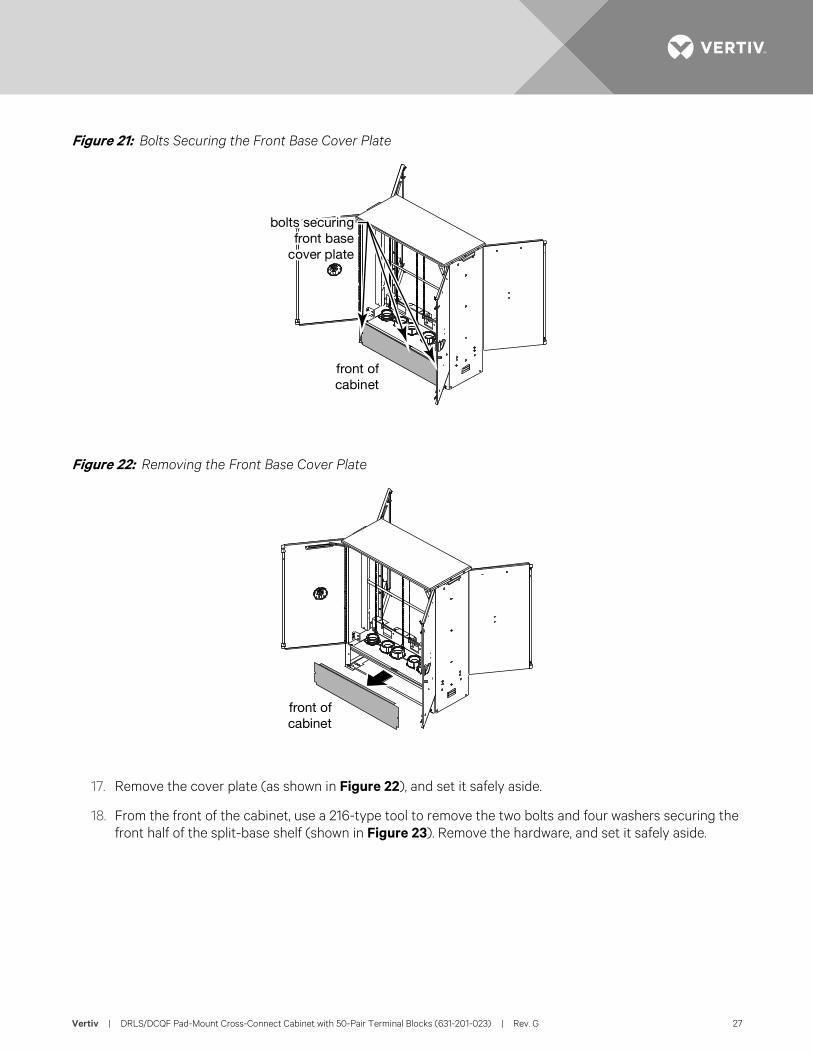
Figure 21: Bolts Securing the Front Base Cover Plate
Figure 22: Removing the Front Base Cover Plate
17. Remove the cover plate (as shown in Figure 22), and set it safely aside.
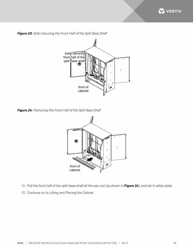
18. From the front of the cabinet, use a 216-type tool to remove the two bolts and four washers securing the front half of the split-base shelf (shown in Figure 23). Remove the hardware, and set it safely aside.
bolts securingfront base
cover plate
front ofcabinet
front ofcabinet
Vertiv | DRLS/DCQF Pad-Mount Cross-Connect Cabinet with 50-Pair Terminal Blocks (631-201-023) | Rev. G 28
Figure 23: Bolts Securing the Front Half of the Split Base Shelf
Figure 24: Removing the Front Half of the Split Base Shelf
19. Pull the front half of the split-base shelf all the way out (as shown in Figure 24), and set it safely aside.
20. Continue on to Lifting and Placing the Cabinet.
bolts securingfront half of thesplit base shelf
front ofcabinet
front ofcabinet
Vertiv | DRLS/DCQF Pad-Mount Cross-Connect Cabinet with 50-Pair Terminal Blocks (631-201-023) | Rev. G 29
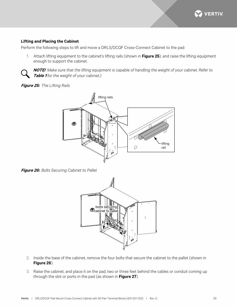
Lifting and Placing the Cabinet Perform the following steps to lift and move a DRLS/DCQF Cross-Connect Cabinet to the pad:
1. Attach lifting equipment to the cabinet’s lifting rails (shown in Figure 25), and raise the lifting equipment enough to support the cabinet.
NOTE! Make sure that the lifting equipment is capable of handling the weight of your cabinet. Refer to Table 1 for the weight of your cabinet.)
Figure 25: The Lifting Rails
Figure 26: Bolts Securing Cabinet to Pallet
2. Inside the base of the cabinet, remove the four bolts that secure the cabinet to the pallet (shown in Figure 26).
3. Raise the cabinet, and place it on the pad, two or three feet behind the cables or conduit coming up through the slot or ports in the pad (as shown in Figure 27).
liftingrail
lifting rails
bolts securingcabinet to pallet
Vertiv | DRLS/DCQF Pad-Mount Cross-Connect Cabinet with 50-Pair Terminal Blocks (631-201-023) | Rev. G 30
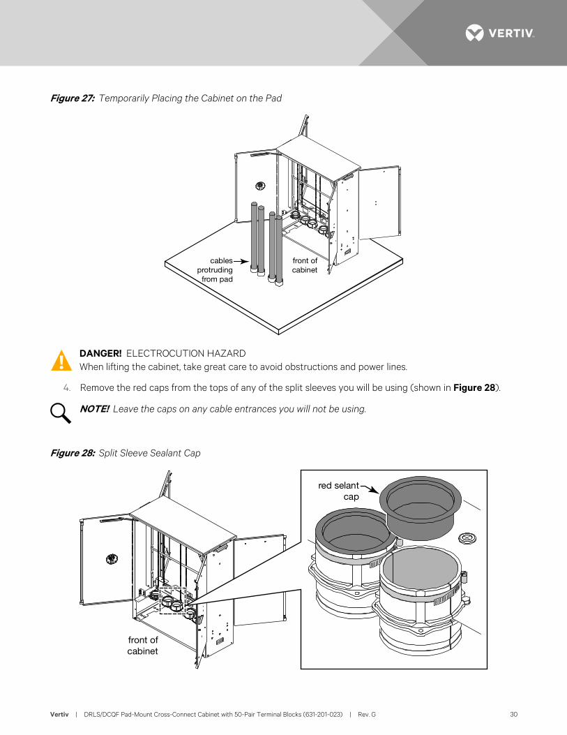
Figure 27: Temporarily Placing the Cabinet on the Pad
DANGER! ELECTROCUTION HAZARD When lifting the cabinet, take great care to avoid obstructions and power lines.
4. Remove the red caps from the tops of any of the split sleeves you will be using (shown in Figure 28).
NOTE! Leave the caps on any cable entrances you will not be using.
Figure 28: Split Sleeve Sealant Cap
cablesprotruding
from pad
front ofcabinet
red selantcap
front ofcabinet
Vertiv | DRLS/DCQF Pad-Mount Cross-Connect Cabinet with 50-Pair Terminal Blocks (631-201-023) | Rev. G 31
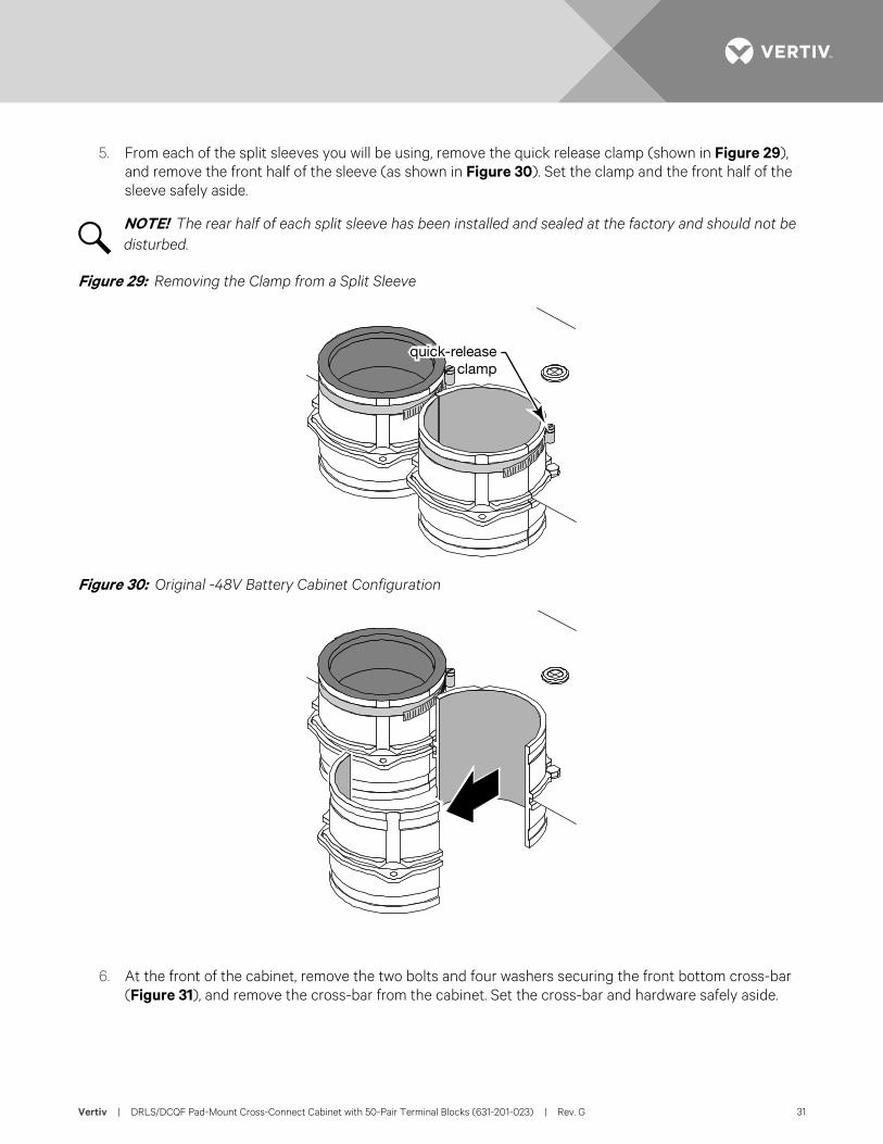
5. From each of the split sleeves you will be using, remove the quick release clamp (shown in Figure 29), and remove the front half of the sleeve (as shown in Figure 30). Set the clamp and the front half of the sleeve safely aside.
NOTE! The rear half of each split sleeve has been installed and sealed at the factory and should not be disturbed.
Figure 29: Removing the Clamp from a Split Sleeve
Figure 30: Original -48V Battery Cabinet Configuration
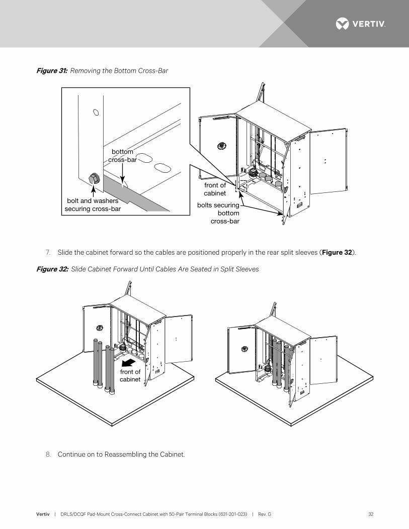
6. At the front of the cabinet, remove the two bolts and four washers securing the front bottom cross-bar (Figure 31), and remove the cross-bar from the cabinet. Set the cross-bar and hardware safely aside.
quick-releaseclamp
Vertiv | DRLS/DCQF Pad-Mount Cross-Connect Cabinet with 50-Pair Terminal Blocks (631-201-023) | Rev. G 32
Figure 31: Removing the Bottom Cross-Bar
7. Slide the cabinet forward so the cables are positioned properly in the rear split sleeves (Figure 32).
Figure 32: Slide Cabinet Forward Until Cables Are Seated in Split Sleeves
8. Continue on to Reassembling the Cabinet.
bolts securingbottom
cross-bar
bolt and washerssecuring cross-bar
bottomcross-bar
front ofcabinet
front ofcabinet
Vertiv | DRLS/DCQF Pad-Mount Cross-Connect Cabinet with 50-Pair Terminal Blocks (631-201-023) | Rev. G 33
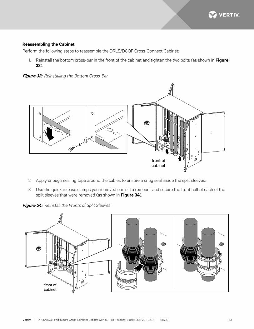
Reassembling the Cabinet Perform the following steps to reassemble the DRLS/DCQF Cross-Connect Cabinet:
1. Reinstall the bottom cross-bar in the front of the cabinet and tighten the two bolts (as shown in Figure 33).
Figure 33: Reinstalling the Bottom Cross-Bar
2. Apply enough sealing tape around the cables to ensure a snug seal inside the split sleeves.
3. Use the quick release clamps you removed earlier to remount and secure the front half of each of the split sleeves that were removed (as shown in Figure 34).
Figure 34: Reinstall the Fronts of Split Sleeves
front ofcabinet
front ofcabinet
Vertiv | DRLS/DCQF Pad-Mount Cross-Connect Cabinet with 50-Pair Terminal Blocks (631-201-023) | Rev. G 34
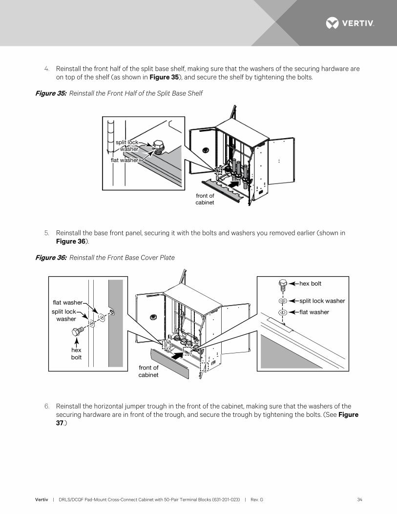
4. Reinstall the front half of the split base shelf, making sure that the washers of the securing hardware are on top of the shelf (as shown in Figure 35), and secure the shelf by tightening the bolts.
Figure 35: Reinstall the Front Half of the Split Base Shelf
5. Reinstall the base front panel, securing it with the bolts and washers you removed earlier (shown in Figure 36).
Figure 36: Reinstall the Front Base Cover Plate
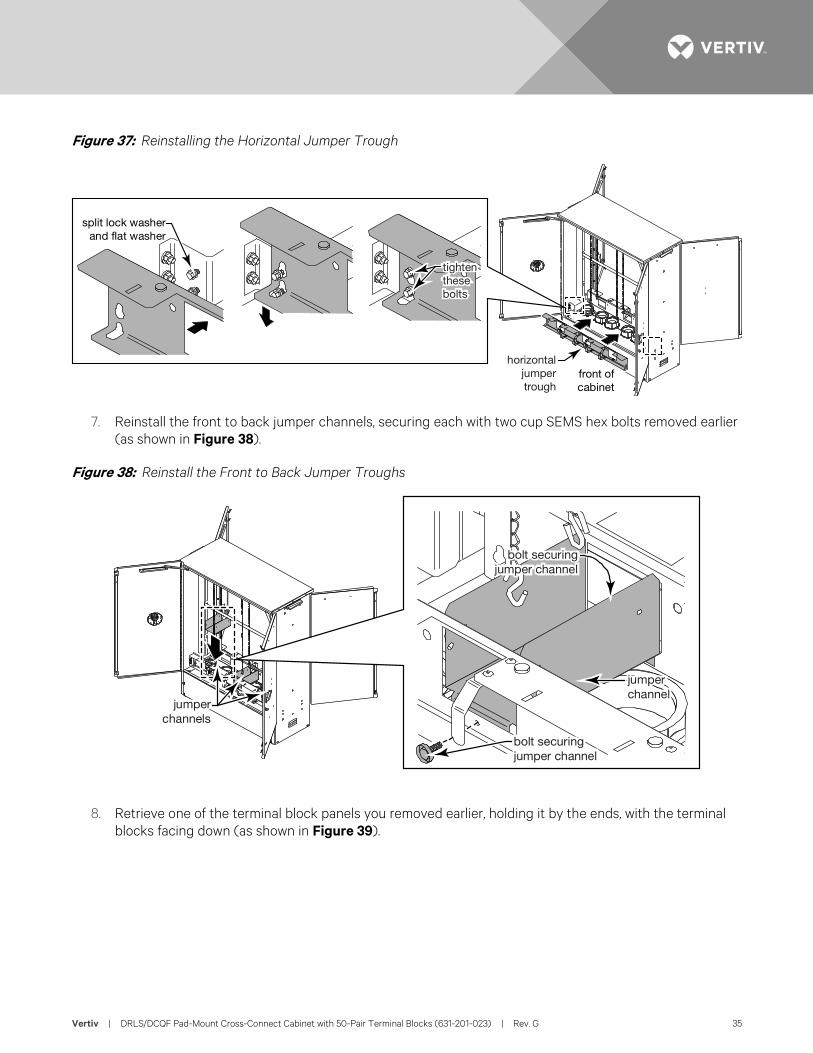
6. Reinstall the horizontal jumper trough in the front of the cabinet, making sure that the washers of the securing hardware are in front of the trough, and secure the trough by tightening the bolts. (See Figure 37.)
split lockwasher
flat washer
split lockwasher
flat washer
front ofcabinet
hex bolt
split lock washer
flat washer
hexbolt
flat washer
split lockwasher
front ofcabinet
Vertiv | DRLS/DCQF Pad-Mount Cross-Connect Cabinet with 50-Pair Terminal Blocks (631-201-023) | Rev. G 35
Figure 37: Reinstalling the Horizontal Jumper Trough
7. Reinstall the front to back jumper channels, securing each with two cup SEMS hex bolts removed earlier (as shown in Figure 38).
Figure 38: Reinstall the Front to Back Jumper Troughs
8. Retrieve one of the terminal block panels you removed earlier, holding it by the ends, with the terminal blocks facing down (as shown in Figure 39).
horizontaljumpertrough
tightenthesebolts
split lock washerand flat washer
front ofcabinet
jumperchannels
jumperchannel
bolt securingjumper channel
bolt securingjumper channel
Vertiv | DRLS/DCQF Pad-Mount Cross-Connect Cabinet with 50-Pair Terminal Blocks (631-201-023) | Rev. G 36
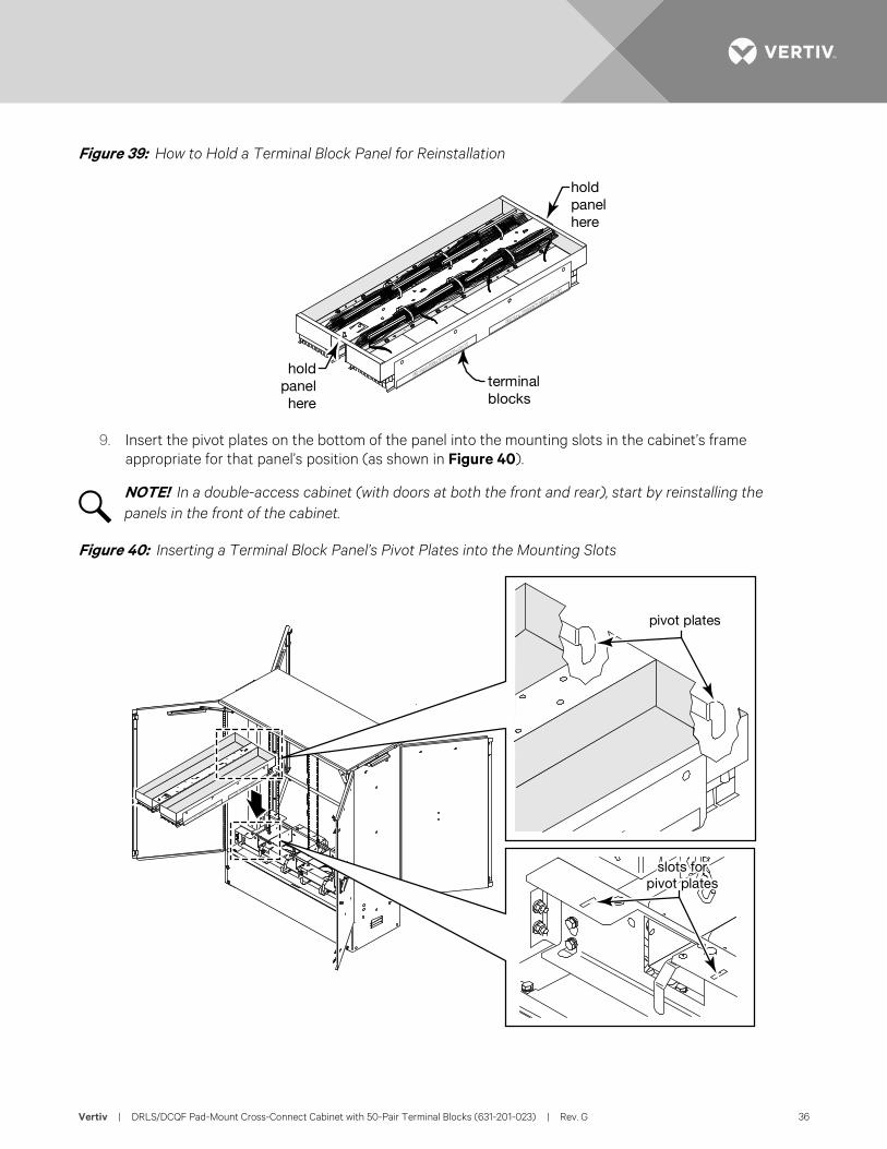
Figure 39: How to Hold a Terminal Block Panel for Reinstallation
9. Insert the pivot plates on the bottom of the panel into the mounting slots in the cabinet’s frame appropriate for that panel’s position (as shown in Figure 40).
NOTE! In a double-access cabinet (with doors at both the front and rear), start by reinstalling the panels in the front of the cabinet.
Figure 40: Inserting a Terminal Block Panel’s Pivot Plates into the Mounting Slots
terminalblocks
holdpanelhere
holdpanelhere
slots forpivot plates
pivot plates
Vertiv | DRLS/DCQF Pad-Mount Cross-Connect Cabinet with 50-Pair Terminal Blocks (631-201-023) | Rev. G 37
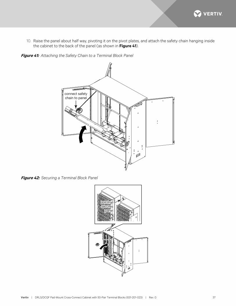
10. Raise the panel about half way, pivoting it on the pivot plates, and attach the safety chain hanging inside the cabinet to the back of the panel (as shown in Figure 41).
Figure 41: Attaching the Safety Chain to a Terminal Block Panel
Figure 42: Securing a Terminal Block Panel
connect safetychain to panel
bolt thatsecures
panel
Vertiv | DRLS/DCQF Pad-Mount Cross-Connect Cabinet with 50-Pair Terminal Blocks (631-201-023) | Rev. G 38
11. Raise the panel into an upright position, and use a 216-type tool to secure the panel to the cabinet’s frame by tightening the captive cup SEMS hex-head bolt at the top center of the panel (as shown in Figure 42).
12. Are there more terminal block panels to reinstall in the front of the cabinet?
• If no, then continue on to Step 13.
• If yes, then return to Step 8 to install another panel in the front of the cabinet.
13. Will you be preparing the cables and splicing the wire pairs now or later?
• If now, then proceed to Cable Installation and Splicing.
• If later, then continue on to Step 14.
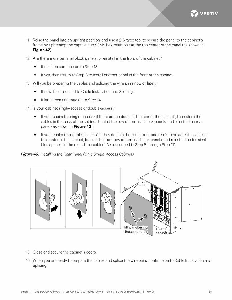
14. Is your cabinet single-access or double-access?
• If your cabinet is single-access (if there are no doors at the rear of the cabinet), then store the cables in the back of the cabinet, behind the row of terminal block panels, and reinstall the rear panel (as shown in Figure 43).
• If your cabinet is double-access (if it has doors at both the front and rear), then store the cables in the center of the cabinet, behind the front row of terminal block panels, and reinstall the terminal block panels in the rear of the cabinet (as described in Step 8 through Step 11).
Figure 43: Installing the Rear Panel (On a Single-Access Cabinet)
15. Close and secure the cabinet’s doors.
16. When you are ready to prepare the cables and splice the wire pairs, continue on to Cable Installation and Splicing.
lift panel usingthese handles
rear ofcabinet
Vertiv | DRLS/DCQF Pad-Mount Cross-Connect Cabinet with 50-Pair Terminal Blocks (631-201-023) | Rev. G 39
CABLE INSTALLATION AND SPLICING Cable Preparation You Will Need To prepare the cables for splicing, you will need to provide the following:
• a 216-type tool;
• a cutting tool to remove the cable sheath;
• a ground rod that meets your local requirements;
• a ground cable that meets your local requirements; and
• a grounding bond clamp and bond strap for each cable that meets your local requirements.
Procedure Perform the following steps to prepare the cable:
1. If the doors of the cabinet are not already open, then use a 216-type tool to open the doors, and secure the open doors with the wind latches. (See Doors for information on the operation of the door latches and wind latches.)
NOTE! Remember that a double-access cabinet has doors at both the front and rear of the cabinet.
2. Is your cabinet single-access or double-access?
• If your cabinet is single-access (if there are no doors at the rear of the cabinet) and if the cabinet’s rear panel has not already been removed, then remove it.)
• If your cabinet is double-access (if there are doors at both the front and the rear of the cabinet) and the terminal block panels have not already been removed from the rear of the cabinet, then remove them.
3. On each cable, mark the cable sheath 4 inches (10 cm) above the collar.
4. Remove the outer polyethylene jacket and underlying metallic shield from each cable.
5. Remove the core wrap from the end of each cable.
6. You may have local practices for cable preparation that supersede the instructions in On each cable, mark the cable sheath 4 inches (10 cm) above the collar. through Remove the core wrap from the end of each cable.
7. Install the ground rod and ground wire according to local practices.
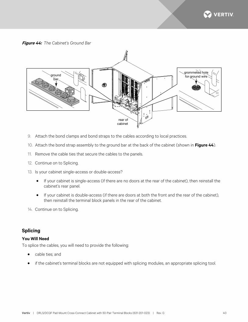
8. Run the ground wire up through the grommeted hole in the cabinet’s split base panel (shown in Figure 44), and attach the ground wire to the cabinet’s ground bar (shown in Figure 44).
Vertiv | DRLS/DCQF Pad-Mount Cross-Connect Cabinet with 50-Pair Terminal Blocks (631-201-023) | Rev. G 40
Figure 44: The Cabinet’s Ground Bar
9. Attach the bond clamps and bond straps to the cables according to local practices.
10. Attach the bond strap assembly to the ground bar at the back of the cabinet (shown in Figure 44).
11. Remove the cable ties that secure the cables to the panels.
12. Continue on to Splicing.
13. Is your cabinet single-access or double-access?
• If your cabinet is single-access (if there are no doors at the rear of the cabinet), then reinstall the cabinet’s rear panel.
• If your cabinet is double-access (if there are doors at both the front and the rear of the cabinet), then reinstall the terminal block panels in the rear of the cabinet.
14. Continue on to Splicing.
Splicing You Will Need To splice the cables, you will need to provide the following:
• cable ties; and
• if the cabinet’s terminal blocks are not equipped with splicing modules, an appropriate splicing tool.
rear ofcabinet
grommeted holefor ground wireground
bar
Vertiv | DRLS/DCQF Pad-Mount Cross-Connect Cabinet with 50-Pair Terminal Blocks (631-201-023) | Rev. G 41
Procedure Perform the following steps to splice wire pairs:
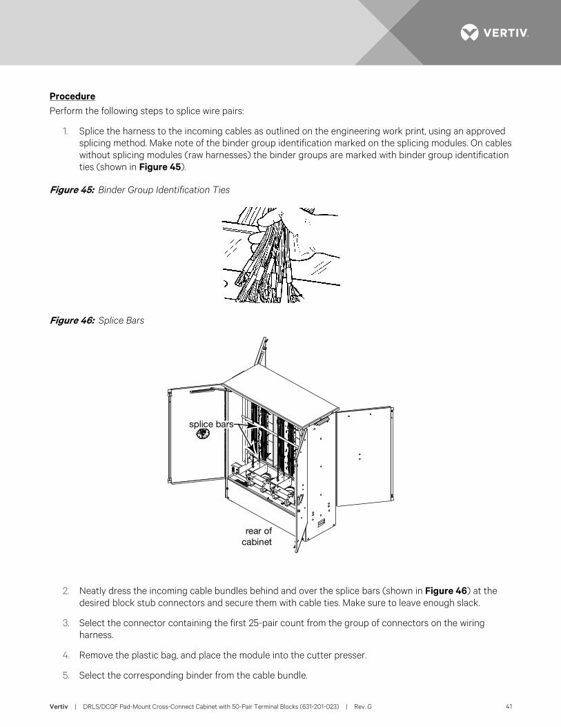
1. Splice the harness to the incoming cables as outlined on the engineering work print, using an approved splicing method. Make note of the binder group identification marked on the splicing modules. On cables without splicing modules (raw harnesses) the binder groups are marked with binder group identification ties (shown in Figure 45).
Figure 45: Binder Group Identification Ties
Figure 46: Splice Bars
2. Neatly dress the incoming cable bundles behind and over the splice bars (shown in Figure 46) at the desired block stub connectors and secure them with cable ties. Make sure to leave enough slack.
3. Select the connector containing the first 25-pair count from the group of connectors on the wiring harness.
4. Remove the plastic bag, and place the module into the cutter presser.
5. Select the corresponding binder from the cable bundle.
rear ofcabinet
splice bars
Vertiv | DRLS/DCQF Pad-Mount Cross-Connect Cabinet with 50-Pair Terminal Blocks (631-201-023) | Rev. G 42
6. Observing the color code, place the conductors in the connector module.
7. Leave enough slack so there will be no stress placed on the conductor when the panel is raised and lowered.
8. Seat the conductors and place the cap on the connector module.
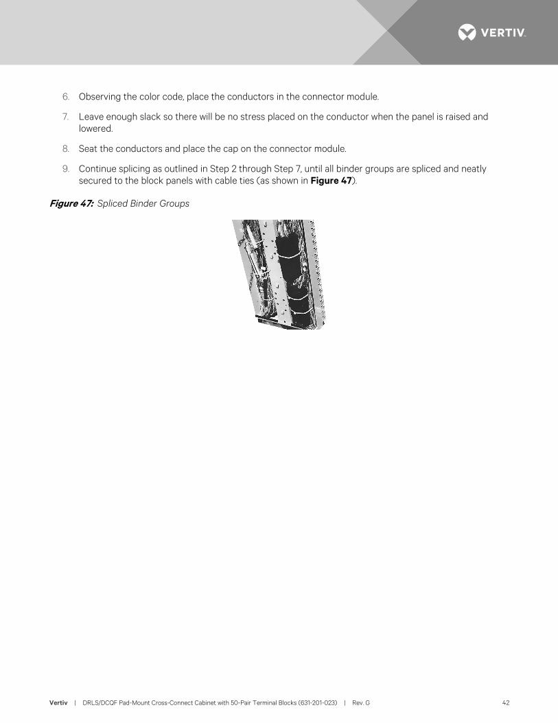
9. Continue splicing as outlined in Step 2 through Step 7, until all binder groups are spliced and neatly secured to the block panels with cable ties (as shown in Figure 47).
Figure 47: Spliced Binder Groups
Vertiv | DRLS/DCQF Pad-Mount Cross-Connect Cabinet with 50-Pair Terminal Blocks (631-201-023) | Rev. G 43
JUMPER WIRING Overview Before running cross-connect or jumper wire, make sure that you are familiar with the numbering sequence used in the cabinet. Feeder and distribution fields are color-coded.
• Feeder cables are terminated in the center field, with pair numbers marked in green.
• Distribution cables are terminated in the outer field, with pair numbers marked in blue.
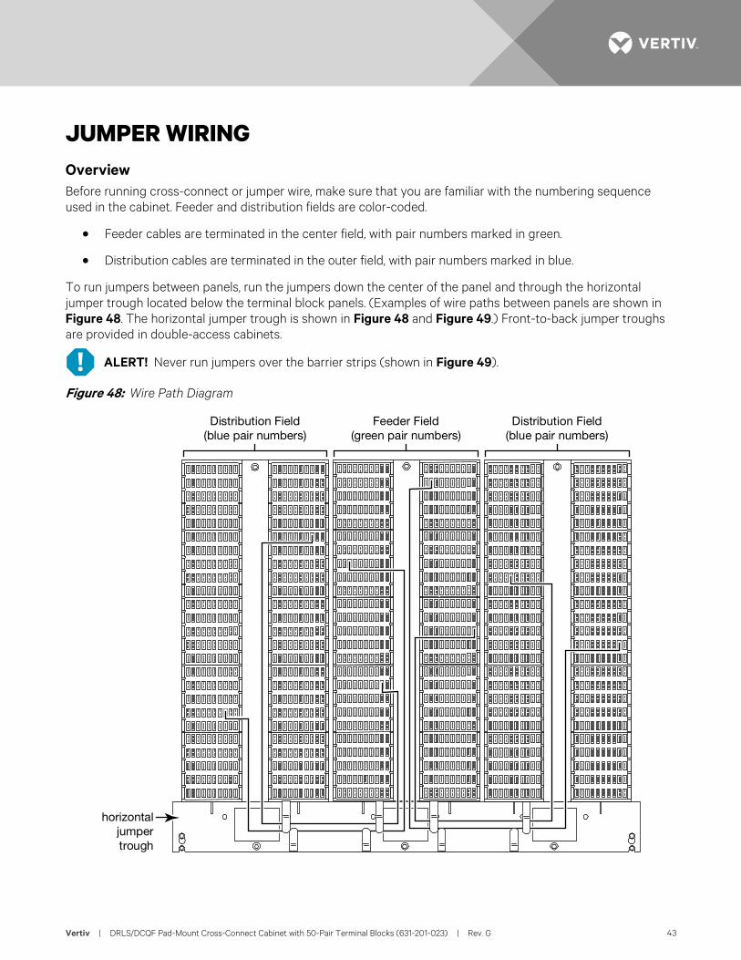
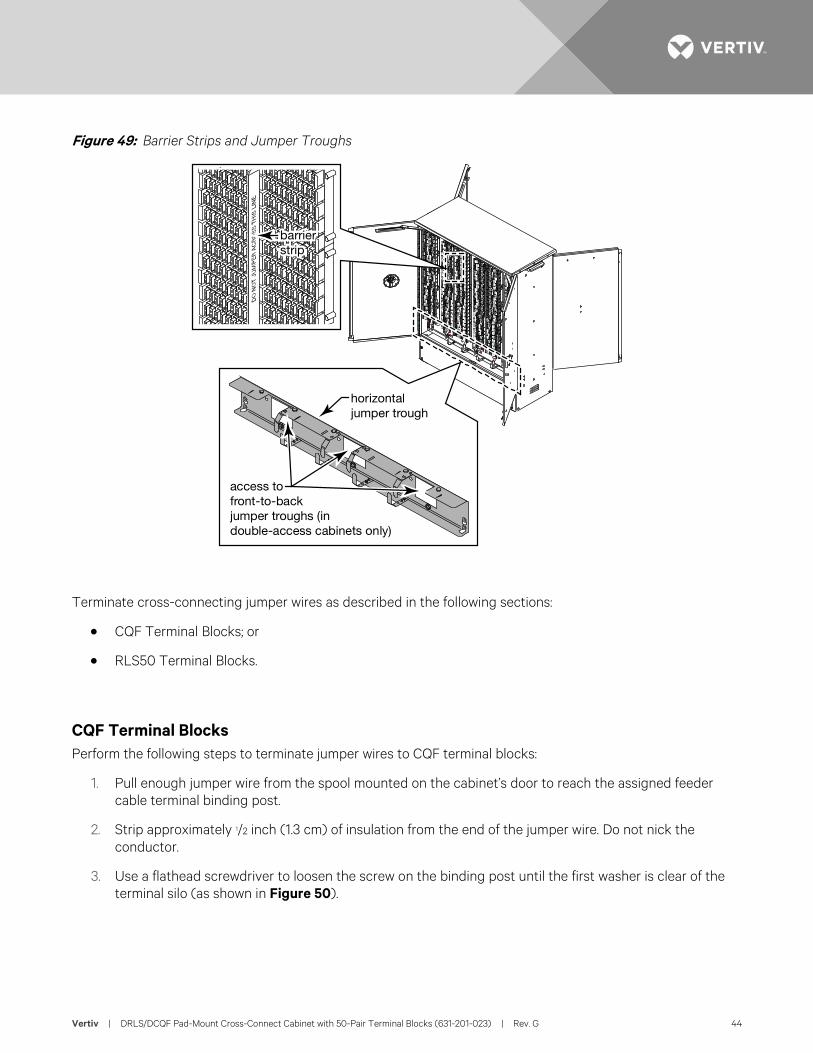
To run jumpers between panels, run the jumpers down the center of the panel and through the horizontal jumper trough located below the terminal block panels. (Examples of wire paths between panels are shown in Figure 48. The horizontal jumper trough is shown in Figure 48 and Figure 49.) Front-to-back jumper troughs are provided in double-access cabinets.
ALERT! Never run jumpers over the barrier strips (shown in Figure 49).
Figure 48: Wire Path Diagram
Distribution Field(blue pair numbers)
Distribution Field(blue pair numbers)
Feeder Field(green pair numbers)
horizontaljumpertrough
Vertiv | DRLS/DCQF Pad-Mount Cross-Connect Cabinet with 50-Pair Terminal Blocks (631-201-023) | Rev. G 44
Figure 49: Barrier Strips and Jumper Troughs
Terminate cross-connecting jumper wires as described in the following sections:
• CQF Terminal Blocks; or
• RLS50 Terminal Blocks.
CQF Terminal Blocks Perform the following steps to terminate jumper wires to CQF terminal blocks:
1. Pull enough jumper wire from the spool mounted on the cabinet’s door to reach the assigned feeder cable terminal binding post.
2. Strip approximately 1/2 inch (1.3 cm) of insulation from the end of the jumper wire. Do not nick the conductor.
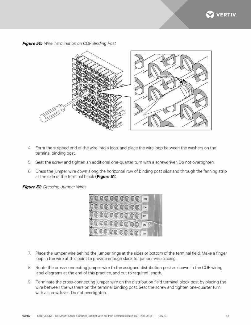
3. Use a flathead screwdriver to loosen the screw on the binding post until the first washer is clear of the terminal silo (as shown in Figure 50).
barrierstrip
horizontaljumper trough
access tofront-to-backjumper troughs (indouble-access cabinets only)
Vertiv | DRLS/DCQF Pad-Mount Cross-Connect Cabinet with 50-Pair Terminal Blocks (631-201-023) | Rev. G 45
Figure 50: Wire Termination on CQF Binding Post
4. Form the stripped end of the wire into a loop, and place the wire loop between the washers on the terminal binding post.
5. Seat the screw and tighten an additional one-quarter turn with a screwdriver. Do not overtighten.
6. Dress the jumper wire down along the horizontal row of binding post silos and through the fanning strip at the side of the terminal block (Figure 51).
Figure 51: Dressing Jumper Wires
7. Place the jumper wire behind the jumper rings at the sides or bottom of the terminal field. Make a finger loop in the wire at this point to provide enough slack for jumper wire tracing.
8. Route the cross-connecting jumper wire to the assigned distribution post as shown in the CQF wiring label diagrams at the end of this practice, and cut to required length.
9. Terminate the cross-connecting jumper wire on the distribution field terminal block post by placing the wire between the washers on the terminal binding post. Seat the screw and tighten one-quarter turn with a screwdriver. Do not overtighten.
washers

Vertiv | DRLS/DCQF Pad-Mount Cross-Connect Cabinet with 50-Pair Terminal Blocks (631-201-023) | Rev. G 46
RLS50 Terminal Blocks ALERT! When terminating to an RLS50 block, do not strip the wires.
Normal Wire Termination on An RLS50 Block For information on terminating jumper wires to RLS50 terminal blocks, see document 641-202-002, RS50 Self-Strip Block Description and Installation.
Dual Wire Termination on An RLS50 Block For information on dual wire termination of jumper wires to RLS50 terminal blocks using Feed-Thru Half-Tap Activators, see document 641-202-009, RS50 Self-Strip Block Feed-Thru Half-Tap Activator Kit Description and Installation.
Vertiv | DRLS/DCQF Pad-Mount Cross-Connect Cabinet with 50-Pair Terminal Blocks (631-201-023) | Rev. G 47
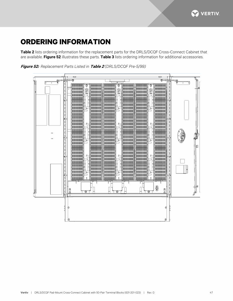
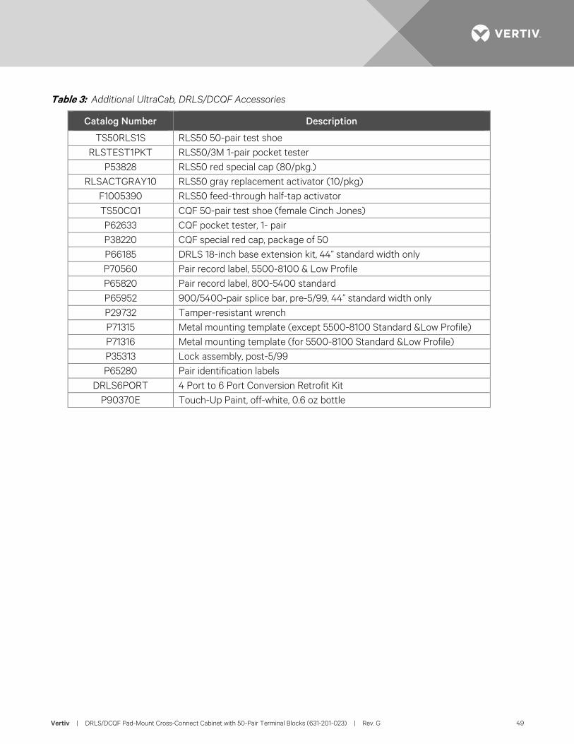
ORDERING INFORMATION Table 2 lists ordering information for the replacement parts for the DRLS/DCQF Cross-Connect Cabinet that are available. Figure 52 illustrates these parts. Table 3 lists ordering information for additional accessories.
Figure 52: Replacement Parts Listed in Table 2 (DRLS/DCQF Pre-5/99)
Vertiv | DRLS/DCQF Pad-Mount Cross-Connect Cabinet with 50-Pair Terminal Blocks (631-201-023) | Rev. G 48
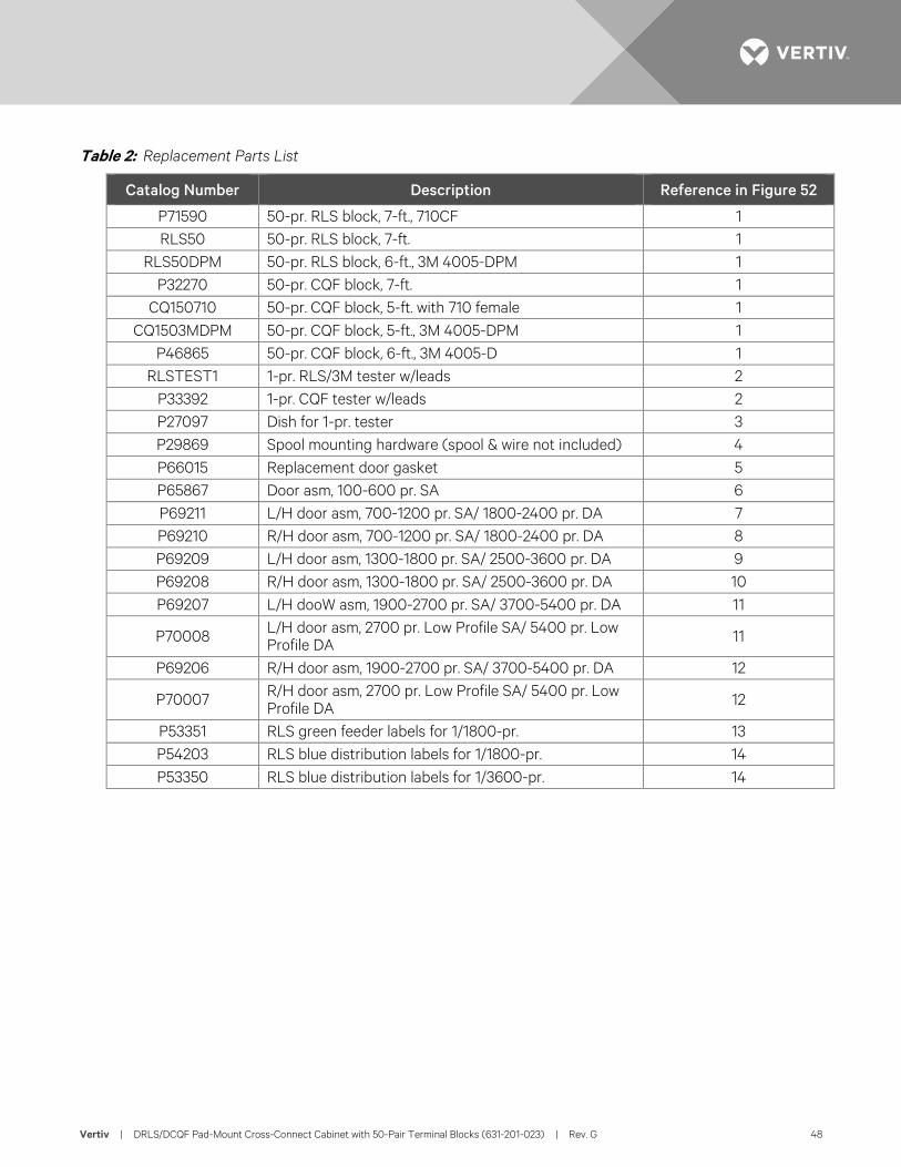
Table 2: Replacement Parts List
Catalog Number Description Reference in Figure 52
P71590 50-pr. RLS block, 7-ft., 710CF 1 RLS50 50-pr. RLS block, 7-ft. 1
RLS50DPM 50-pr. RLS block, 6-ft., 3M 4005-DPM 1 P32270 50-pr. CQF block, 7-ft. 1
CQ150710 50-pr. CQF block, 5-ft. with 710 female 1 CQ1503MDPM 50-pr. CQF block, 5-ft., 3M 4005-DPM 1
P46865 50-pr. CQF block, 6-ft., 3M 4005-D 1 RLSTEST1 1-pr. RLS/3M tester w/leads 2
P33392 1-pr. CQF tester w/leads 2 P27097 Dish for 1-pr. tester 3 P29869 Spool mounting hardware (spool & wire not included) 4 P66015 Replacement door gasket 5 P65867 Door asm, 100-600 pr. SA 6 P69211 L/H door asm, 700-1200 pr. SA/ 1800-2400 pr. DA 7 P69210 R/H door asm, 700-1200 pr. SA/ 1800-2400 pr. DA 8 P69209 L/H door asm, 1300-1800 pr. SA/ 2500-3600 pr. DA 9 P69208 R/H door asm, 1300-1800 pr. SA/ 2500-3600 pr. DA 10 P69207 L/H dooW asm, 1900-2700 pr. SA/ 3700-5400 pr. DA 11
P70008 L/H door asm, 2700 pr. Low Profile SA/ 5400 pr. Low Profile DA 11
P69206 R/H door asm, 1900-2700 pr. SA/ 3700-5400 pr. DA 12
P70007 R/H door asm, 2700 pr. Low Profile SA/ 5400 pr. Low Profile DA 12
P53351 RLS green feeder labels for 1/1800-pr. 13 P54203 RLS blue distribution labels for 1/1800-pr. 14 P53350 RLS blue distribution labels for 1/3600-pr. 14
Vertiv | DRLS/DCQF Pad-Mount Cross-Connect Cabinet with 50-Pair Terminal Blocks (631-201-023) | Rev. G 49
Table 3: Additional UltraCab, DRLS/DCQF Accessories
Catalog Number Description
TS50RLS1S RLS50 50-pair test shoe RLSTEST1PKT RLS50/3M 1-pair pocket tester
P53828 RLS50 red special cap (80/pkg.) RLSACTGRAY10 RLS50 gray replacement activator (10/pkg)
F1005390 RLS50 feed-through half-tap activator TS50CQ1 CQF 50-pair test shoe (female Cinch Jones) P62633 CQF pocket tester, 1- pair P38220 CQF special red cap, package of 50 P66185 DRLS 18-inch base extension kit, 44” standard width only P70560 Pair record label, 5500-8100 & Low Profile P65820 Pair record label, 800-5400 standard P65952 900/5400-pair splice bar, pre-5/99, 44” standard width only P29732 Tamper-resistant wrench P71315 Metal mounting template (except 5500-8100 Standard &Low Profile) P71316 Metal mounting template (for 5500-8100 Standard &Low Profile) P35313 Lock assembly, post-5/99 P65280 Pair identification labels
DRLS6PORT 4 Port to 6 Port Conversion Retrofit Kit P90370E Touch-Up Paint, off-white, 0.6 oz bottle

VertivCo.com | Vertiv Headquarters, 1050 Dearborn Drive, Columbus, OH, 43085, USA 631-201-023 (RG 10/17)