Embed Size (px)
Citation preview
PROGRAMMABLE ATMOSPHERE AND TEMPERATURE CONTROLLER
Series 9205
OPERATIONS MANUAL
Super Systems Inc. 7205 Edington Drive
Cincinnati, OH 45249 513-772-0060
Fax: 513-772-9466 www.supersystems.com
Series 9205 Operations Manual Rev A 1
Super Systems Inc. USA Office
Corporate Headquarters 7205 Edington Drive Cincinnati, OH 45249
Phone: (513) 772-0060 http://www.supersystems.com
Super Systems Europe Units 3 & 4, 17 Reddicap Trading Estate,
Sutton Coldfield, West Midlands B75 7BU
UNITED KINGDOM Phone: +44 (0) 121 329 2627
http://www.supersystemseurope.com
Super Systems México Sistemas Superiores Integrales S de RL de CV
Calle 3 Int.: 11. Zona Ind. Benito Juarez
Querétaro, Qro. Méx. C.P.: 76120
Phone: +52 (442) 210 2459 http://www.supersystems.com.mx
Super Systems China No. 335 XianXia Road
Room 308 Shanghai, CHINA
200336 Phone: +86 21 5206 5701/2
http://www.supersystems.com
Series 9205 Operations Manual Rev A 2
Table of Contents INSTALLATION SAFETY REQUIREMENTS ---------------------------------------------------------------------------------------------------- 5
CHAPTER 1 - OVERVIEW ------------------------------------------------------------------------------------------------------------------------- 8
MOUNTING ----------------------------------------------------------------------------------------------------------------------------------------- 9 DIMENSIONAL DRAWINGS ----------------------------------------------------------------------------------------------------------------------- 10 WIRING ------------------------------------------------------------------------------------------------------------------------------------------- 12 ELECTRICAL INSTALLATION ----------------------------------------------------------------------------------------------------------------------- 12 PIN OUT ------------------------------------------------------------------------------------------------------------------------------------------ 13 ANCILLARY ITEMS --------------------------------------------------------------------------------------------------------------------------------- 13 SETUP --------------------------------------------------------------------------------------------------------------------------------------------- 14 ADDITIONAL FEATURES --------------------------------------------------------------------------------------------------------------------------- 14 ETHERNET CONNECTIONS ------------------------------------------------------------------------------------------------------------------------ 14 INSTRUMENT START-UP -------------------------------------------------------------------------------------------------------------------------- 15 FLASH CARD & FLASH CARD READER ------------------------------------------------------------------------------------------------------------ 15 OPERATOR INTERFACE SCREEN SAVER ----------------------------------------------------------------------------------------------------------- 15 DEFAULT STATUS SCREEN ------------------------------------------------------------------------------------------------------------------------ 15 MENU --------------------------------------------------------------------------------------------------------------------------------------------- 16 CHART --------------------------------------------------------------------------------------------------------------------------------------------- 16 CHART SUB MENU ------------------------------------------------------------------------------------------------------------------------------- 18 RECIPE -------------------------------------------------------------------------------------------------------------------------------------------- 19 LOOPS --------------------------------------------------------------------------------------------------------------------------------------------- 20 ACK (ALARM ACKNOWLEDGE) ------------------------------------------------------------------------------------------------------------------- 20 DATA LOGGING USING FLASH CARD ------------------------------------------------------------------------------------------------------------- 21
CHAPTER 2 - CONFIGURATION --------------------------------------------------------------------------------------------------------------- 22
MENU (CONFIGURATION) ----------------------------------------------------------------------------------------------------------------------- 22 About ----------------------------------------------------------------------------------------------------------------------------------------- 24 Maintenance ------------------------------------------------------------------------------------------------------------------------------- 24 Logs ------------------------------------------------------------------------------------------------------------------------------------------- 24 Probe Manager ---------------------------------------------------------------------------------------------------------------------------- 25 Slave Communications Status ---------------------------------------------------------------------------------------------------------- 26 Load TC/Auxiliary Analog Input -------------------------------------------------------------------------------------------------------- 26 Manual Event Control -------------------------------------------------------------------------------------------------------------------- 26 Shutdown ------------------------------------------------------------------------------------------------------------------------------------ 27 Probe Burnoff Setup ---------------------------------------------------------------------------------------------------------------------- 27 PID Loop Setup ----------------------------------------------------------------------------------------------------------------------------- 28 Recipe Edit ---------------------------------------------------------------------------------------------------------------------------------- 33 Load T/C Configuration ------------------------------------------------------------------------------------------------------------------ 34 Trend Chart Edit --------------------------------------------------------------------------------------------------------------------------- 34 Communications Setup ------------------------------------------------------------------------------------------------------------------ 36 Slave Instrument Setup ------------------------------------------------------------------------------------------------------------------ 38 Zone Assignments ------------------------------------------------------------------------------------------------------------------------ 41 Furnace Setup ------------------------------------------------------------------------------------------------------------------------------ 42 Default Wait Limits ----------------------------------------------------------------------------------------------------------------------- 46 Alarm Setup --------------------------------------------------------------------------------------------------------------------------------- 46 Thermocouple Check --------------------------------------------------------------------------------------------------------------------- 48 Relay Assignments ------------------------------------------------------------------------------------------------------------------------ 48 Analog Input Setup ------------------------------------------------------------------------------------------------------------------------ 49 Analog Output Setup --------------------------------------------------------------------------------------------------------------------- 51 Alarm Polarity ------------------------------------------------------------------------------------------------------------------------------ 52 Redundant TC Setup ---------------------------------------------------------------------------------------------------------------------- 53
Series 9205 Operations Manual Rev A 3
Event Hold/Reset -------------------------------------------------------------------------------------------------------------------------- 53 Security -------------------------------------------------------------------------------------------------------------------------------------- 55 Curve Entry ---------------------------------------------------------------------------------------------------------------------------------- 56 Alternate PID Setup ----------------------------------------------------------------------------------------------------------------------- 57 Aux Analog Input Setup ------------------------------------------------------------------------------------------------------------------ 58 TC Type mV Range Chart ---------------------------------------------------------------------------------------------------------------- 59 Calibration ---------------------------------------------------------------------------------------------------------------------------------- 59 Configuration ------------------------------------------------------------------------------------------------------------------------------- 61 A/I Module Offset Correction ----------------------------------------------------------------------------------------------------------- 71 Aux Setpoint Configuration ------------------------------------------------------------------------------------------------------------- 71 T/C Extension Correction Curves ------------------------------------------------------------------------------------------------------- 71 Generic Instrument Setup --------------------------------------------------------------------------------------------------------------- 72 DF1 Configuration ------------------------------------------------------------------------------------------------------------------------- 73 Tuning Assistant --------------------------------------------------------------------------------------------------------------------------- 74 PLC Data Mapping ------------------------------------------------------------------------------------------------------------------------ 75 Analog Input Correction Curves -------------------------------------------------------------------------------------------------------- 76 Instrument Calculation ------------------------------------------------------------------------------------------------------------------- 76
CHAPTER 3 – CONFIGURATOR 2.0 MENUS ----------------------------------------------------------------------------------------------- 79
BURNOFF ----------------------------------------------------------------------------------------------------------------------------------------- 79 SLAVE INSTRUMENTS ----------------------------------------------------------------------------------------------------------------------------- 81 AUXILIARY ANALOG INPUT ----------------------------------------------------------------------------------------------------------------------- 81 MANUAL EVENT CONTROL ----------------------------------------------------------------------------------------------------------------------- 82 PROBE BURNOFF SETUP -------------------------------------------------------------------------------------------------------------------------- 83 PID LOOP SETUP --------------------------------------------------------------------------------------------------------------------------------- 85 EVENT RUN PROGRAM SETUP ------------------------------------------------------------------------------------------------------------------- 90 LOAD T/C CONFIGURATION --------------------------------------------------------------------------------------------------------------------- 90 PORT SETUP -------------------------------------------------------------------------------------------------------------------------------------- 91 SLAVE INSTRUMENT SETUP ---------------------------------------------------------------------------------------------------------------------- 94 ZONE ASSIGNMENTS ----------------------------------------------------------------------------------------------------------------------------- 95 FURNACE SETUP ---------------------------------------------------------------------------------------------------------------------------------- 97 DEFAULT WAIT LIMITS ------------------------------------------------------------------------------------------------------------------------- 102 ALARM SETUP ---------------------------------------------------------------------------------------------------------------------------------- 103 THERMOCOUPLE CHECK ------------------------------------------------------------------------------------------------------------------------ 104 RELAY ASSIGNMENTS --------------------------------------------------------------------------------------------------------------------------- 105 RELAY SETPOINTS ------------------------------------------------------------------------------------------------------------------------------- 107 ANALOG INPUT SETUP ------------------------------------------------------------------------------------------------------------------------- 108 ANALOG OUTPUT SETUP ----------------------------------------------------------------------------------------------------------------------- 110 PASSCODE AND ALARM ------------------------------------------------------------------------------------------------------------------------ 111 IP ADDRESS ------------------------------------------------------------------------------------------------------------------------------------- 113 REDUNDANT TC SETUP ------------------------------------------------------------------------------------------------------------------------ 113 EVENT CONTROL -------------------------------------------------------------------------------------------------------------------------------- 114 SET MENU SECURITY --------------------------------------------------------------------------------------------------------------------------- 115 CURVE ENTRY ----------------------------------------------------------------------------------------------------------------------------------- 115 ALTERNATE PID SETUP ------------------------------------------------------------------------------------------------------------------------- 116 SSI ANALOG INPUT SETUP --------------------------------------------------------------------------------------------------------------------- 117 SSI CONFIGURATION AND CALIBRATION------------------------------------------------------------------------------------------------------- 118
Overview ---------------------------------------------------------------------------------------------------------------------------------- 118 Equipment needed ---------------------------------------------------------------------------------------------------------------------- 118 Notes --------------------------------------------------------------------------------------------------------------------------------------- 118 User Calibration ------------------------------------------------------------------------------------------------------------------------- 118 Full Calibration --------------------------------------------------------------------------------------------------------------------------- 120 TC Type mV Range Chart -------------------------------------------------------------------------------------------------------------- 121
Series 9205 Operations Manual Rev A 4
AUXILIARY INPUT OFFSET CORRECTION ------------------------------------------------------------------------------------------------------- 122 AUX SETPOINT CONFIGURATION --------------------------------------------------------------------------------------------------------------- 123 TC EXTENSION CORRECTION CURVES --------------------------------------------------------------------------------------------------------- 123 GENERIC INSTRUMENT SETUPS ---------------------------------------------------------------------------------------------------------------- 124
Configure Generic Instruments ------------------------------------------------------------------------------------------------------- 124 Configure IP Addresses ----------------------------------------------------------------------------------------------------------------- 125 Configure Block Writes ----------------------------------------------------------------------------------------------------------------- 125
DF1 CONFIGURATION -------------------------------------------------------------------------------------------------------------------------- 125 TUNING ASSISTANT ----------------------------------------------------------------------------------------------------------------------------- 126 PLC DATA MAPPING --------------------------------------------------------------------------------------------------------------------------- 128 ANALOG INPUT CORRECTION CURVES --------------------------------------------------------------------------------------------------------- 128 INSTRUMENT CALCULATION -------------------------------------------------------------------------------------------------------------------- 128 PROGRAMMER DESCRIPTION ------------------------------------------------------------------------------------------------------------------ 131 WAIT -------------------------------------------------------------------------------------------------------------------------------------------- 131 WAIT UP ---------------------------------------------------------------------------------------------------------------------------------------- 132 WAIT DOWN ----------------------------------------------------------------------------------------------------------------------------------- 132 WAIT IN A GUARANTEED SOAK ---------------------------------------------------------------------------------------------------------------- 134 GUARANTEE HIGH ASSIGNMENT--------------------------------------------------------------------------------------------------------------- 135 SAMPLE EVENT ASSIGNMENTS ----------------------------------------------------------------------------------------------------------------- 136 FLASH CARD MANAGEMENT ------------------------------------------------------------------------------------------------------------------- 136 SLAVE INSTRUMENT MAPPING----------------------------------------------------------------------------------------------------------------- 140
Atmosphere Instruments -------------------------------------------------------------------------------------------------------------- 140 Temperature Instruments ------------------------------------------------------------------------------------------------------------- 143 Events Instruments ---------------------------------------------------------------------------------------------------------------------- 148
9205 ANALOG INPUT BOARD JUMPER SETTINGS --------------------------------------------------------------------------------------------- 151
CHAPTER 4 – OPCODES ---------------------------------------------------------------------------------------------------------------------- 153
WARRANTY ------------------------------------------------------------------------------------------------------------------------------------- 168
APPENDIX A – WIRING DIAGRAM OF SERIES 9205 ----------------------------------------------------------------------------------- 169
APPENDIX B – GUIDE TO BUILDING A RECIPE ------------------------------------------------------------------------------------------ 171
APPENDIX C – SETUP FOR CARBON / DUAL TEMPERATURE FOR QUENCH CONTROL -------------------------------------- 179
APPENDIX D – 9205 INSTRUMENT ALARMS ------------------------------------------------------------------------------------------- 181
APPENDIX E – FACTORY DEFAULT SETTINGS FOR THE 9205 CONTROLLER ---------------------------------------------------- 183
REVISION HISTORY ---------------------------------------------------------------------------------------------------------------------------- 234
Series 9205 Operations Manual Rev A 5
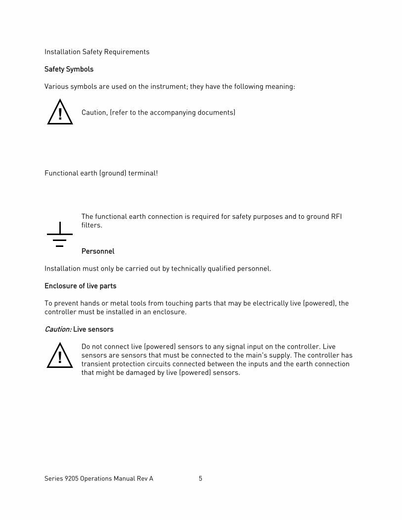
Installation Safety Requirements Safety Symbols Various symbols are used on the instrument; they have the following meaning:
Caution, (refer to the accompanying documents)
Functional earth (ground) terminal!
The functional earth connection is required for safety purposes and to ground RFI filters. Personnel
Installation must only be carried out by technically qualified personnel. Enclosure of live parts To prevent hands or metal tools from touching parts that may be electrically live (powered), the controller must be installed in an enclosure. Caution: Live sensors
Do not connect live (powered) sensors to any signal input on the controller. Live sensors are sensors that must be connected to the main's supply. The controller has transient protection circuits connected between the inputs and the earth connection that might be damaged by live (powered) sensors.
!
!
Series 9205 Operations Manual Rev A 6
Wiring It is important to connect the controller in accordance with the wiring data given in this handbook. Take particular care not to connect AC supplies to the low voltage power supply input. Use copper wires for 24V DC power supply to the instrument. Ensure that the wiring of installations comply with all local wiring regulations. For example in the United Kingdom use the latest version of the IEE wiring regulations, (BS7671). In the USA use NEC Class 1 wiring methods. Power Isolation The installation must include a power isolating switch or circuit breaker. This device should be in close proximity to the controller, within easy reach of the operator and marked as the disconnecting device for the instrument. Earth leakage current Due to RFI Filtering there is an earth leakage current of less than 0.5mA. This may affect the design of an installation of multiple controllers protected by Residual Current Device, (RCD) or Ground Fault Detector, (GFD) type circuit breakers. Over current protection To protect the internal PCB tracking within the controller against excess currents, the AC power supply to the controller and power outputs must be wired through a fuse or circuit breaker specified in the technical specification. Voltage rating The maximum continuous voltage applied between any of the following terminals must not exceed 24V DC
• relay or triac output to logic, DC or sensor connections; • any connection to ground.
The controller should not be wired to VAC. The 24V DC power supply voltage across the connections and between the power supply and ground must not exceed 2.5kV. Where occasional voltage over 2.5kV are expected or measured, the power installation to both the instrument supply and load circuits should include a transient limiting device. These units will typically include gas discharge tubes and metal oxide varistors that limit and control voltage transients on the supply line due to lightning strikes or inductive load switching. Devices are available in a range of energy ratings and should be selected to suit conditions at the installation.
Series 9205 Operations Manual Rev A 7
Conductive pollution Electrically conductive pollution must be excluded from the cabinet in which the controller is mounted. For example, carbon dust is a form of electrically conductive pollution. To secure a suitable atmosphere in conditions of conductive pollution, fit an air filter to the air intake of the cabinet. Where condensation is likely, for example at low temperatures, include a thermostatically controlled heater in the cabinet. Over-temperature protection When designing any control system it is essential to consider what will happen if any part of the system should fail In temperature control applications the primary danger is that the heating will remain constantly on. Apart from spoiling the product, this could damage any process machinery being controlled, or even cause a fire. Reasons why the heating might remain constantly on include:
• the temperature sensor becoming detached from the process; • thermocouple wiring becoming a short circuit; • the controller failing with its heating output constantly on; • an external valve or contactor sticking in the heating condition; • the controller set point set too high.
Where damage or injury is possible, we recommend fitting a separate over temperature protection unit with an independent temperature sensor, which will isolate the heating circuit. Please note that the alarm relays within the controller will not give protection under all failure conditions. Installation requirements for EMC To ensure compliance with the European EMC directive certain installation precautions are necessary as follows:
• When using relay or triac outputs it may be necessary to fit a filter suitable for suppressing the emissions. The filter requirements will depend on the type of load. For typical applications we recommend Schaffner FN321 or FN612.
Routing of wires To minimize the pick-up of electrical noise, the wiring for low voltage dc should be routed away from high-current power cables. Where it is impractical to do this, use shielded cables with the shield grounded at one end.
Series 9205 Operations Manual Rev A 8
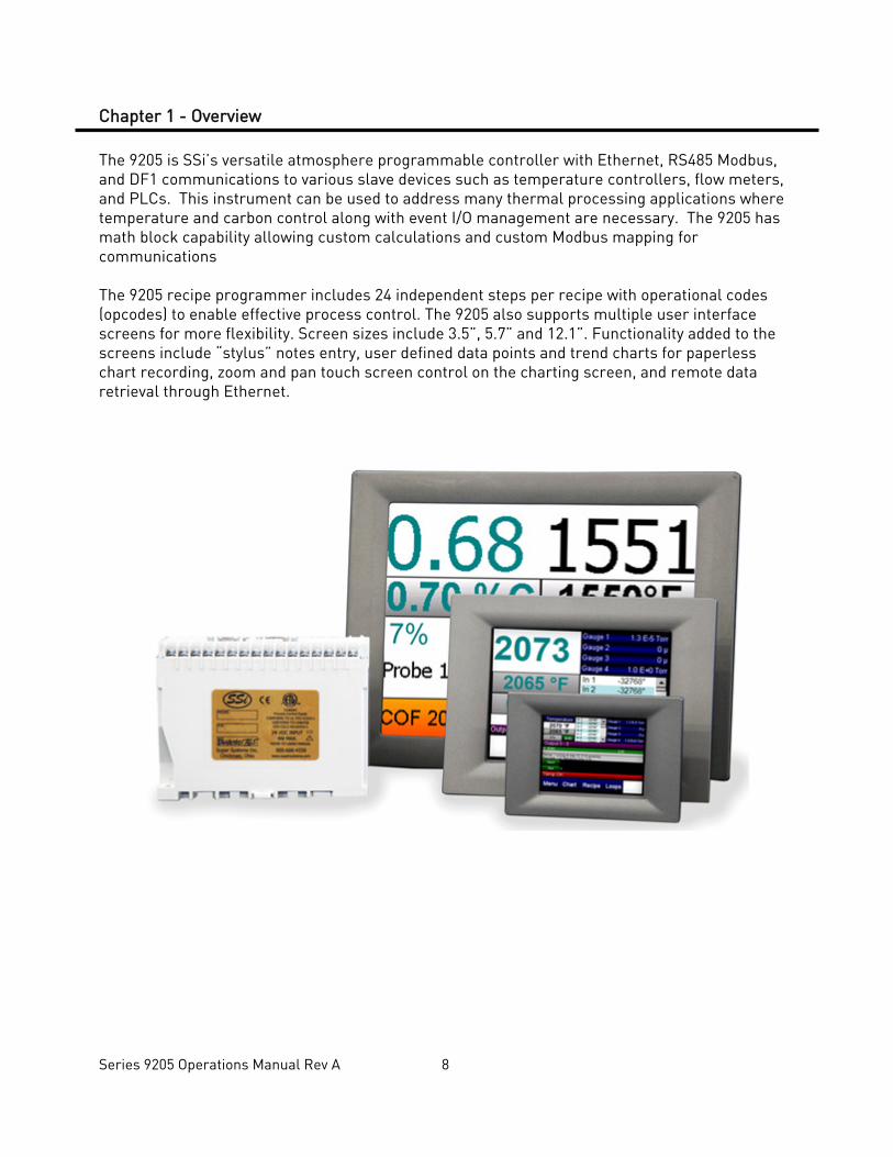
Chapter 1 - Overview The 9205 is SSi’s versatile atmosphere programmable controller with Ethernet, RS485 Modbus, and DF1 communications to various slave devices such as temperature controllers, flow meters, and PLCs. This instrument can be used to address many thermal processing applications where temperature and carbon control along with event I/O management are necessary. The 9205 has math block capability allowing custom calculations and custom Modbus mapping for communications The 9205 recipe programmer includes 24 independent steps per recipe with operational codes (opcodes) to enable effective process control. The 9205 also supports multiple user interface screens for more flexibility. Screen sizes include 3.5”, 5.7” and 12.1”. Functionality added to the screens include “stylus” notes entry, user defined data points and trend charts for paperless chart recording, zoom and pan touch screen control on the charting screen, and remote data retrieval through Ethernet.
Series 9205 Operations Manual Rev A 9
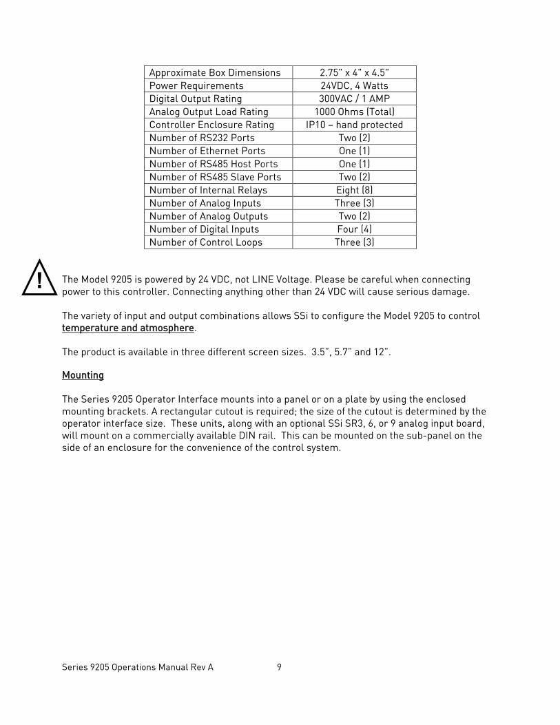
Approximate Box Dimensions 2.75" x 4" x 4.5" Power Requirements 24VDC, 4 Watts Digital Output Rating 300VAC / 1 AMP Analog Output Load Rating 1000 Ohms (Total) Controller Enclosure Rating IP10 – hand protected Number of RS232 Ports Two (2) Number of Ethernet Ports One (1) Number of RS485 Host Ports One (1) Number of RS485 Slave Ports Two (2) Number of Internal Relays Eight (8) Number of Analog Inputs Three (3) Number of Analog Outputs Two (2) Number of Digital Inputs Four (4) Number of Control Loops Three (3)
The Model 9205 is powered by 24 VDC, not LINE Voltage. Please be careful when connecting power to this controller. Connecting anything other than 24 VDC will cause serious damage. The variety of input and output combinations allows SSi to configure the Model 9205 to control temperature and atmosphere. The product is available in three different screen sizes. 3.5”, 5.7” and 12”. Mounting The Series 9205 Operator Interface mounts into a panel or on a plate by using the enclosed mounting brackets. A rectangular cutout is required; the size of the cutout is determined by the operator interface size. These units, along with an optional SSi SR3, 6, or 9 analog input board, will mount on a commercially available DIN rail. This can be mounted on the sub-panel on the side of an enclosure for the convenience of the control system.
!
Series 9205 Operations Manual Rev A 10
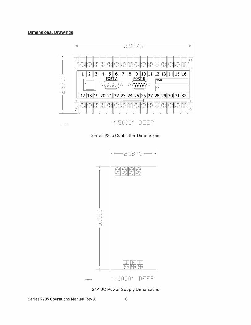
Dimensional Drawings
Series 9205 Controller Dimensions
24V DC Power Supply Dimensions
Series 9205 Operations Manual Rev A 11
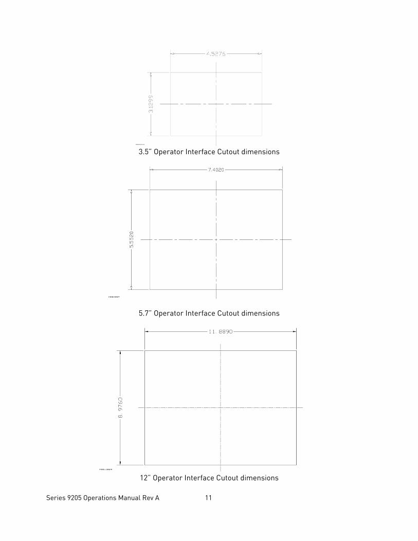
3.5” Operator Interface Cutout dimensions
5.7” Operator Interface Cutout dimensions
12” Operator Interface Cutout dimensions
Series 9205 Operations Manual Rev A 12
Wiring Wiring to the Series 9205 operator interface can be done using 232 or 485 to two connectors, comm1 (232) or comm3 (485). The terminal strip on the lower right rear corner of the operator interface is used to connect 24VDC power. The DB-9 port A connection is used to connect the display via 232 to the Series 9205 PID controller. The controller is connected via RS485 communication to the single-loop controllers. Electrical Installation The Model 9205 requires 24VDC, 4 Watt, single-phase power. A 24 VDC power supply is required and is generally included as part of the Model 9205 system. This power supply has a universal input that can accept between 60 and 265VAC. Power should be applied in accordance with the electrical drawings that have been supplied. Since each installation is unique to the site, the customer is responsible for providing adequate power and making it available to the Model 9205 power supply. SSi requirement: MOV’s must be wired across the isolation relay coil terminals on all isolation relays that are connected to solenoids. Further… MOVs must be connected across the HOT and NEUTRAL wires when the solenoid is wired to them. IT IS AN ABSOLUTE MUST to have the MOVs at BOTH LOCATIONS.
Series 9205 Operations Manual Rev A 13
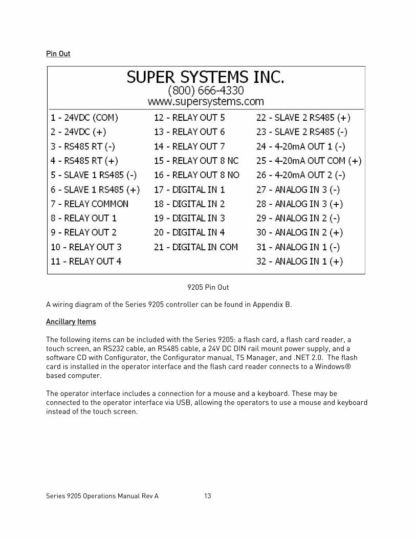
Pin Out
9205 Pin Out A wiring diagram of the Series 9205 controller can be found in Appendix B. Ancillary Items The following items can be included with the Series 9205: a flash card, a flash card reader, a touch screen, an RS232 cable, an RS485 cable, a 24V DC DIN rail mount power supply, and a software CD with Configurator, the Configurator manual, TS Manager, and .NET 2.0. The flash card is installed in the operator interface and the flash card reader connects to a Windows® based computer.
The operator interface includes a connection for a mouse and a keyboard. These may be connected to the operator interface via USB, allowing the operators to use a mouse and keyboard instead of the touch screen.
Series 9205 Operations Manual Rev A 14
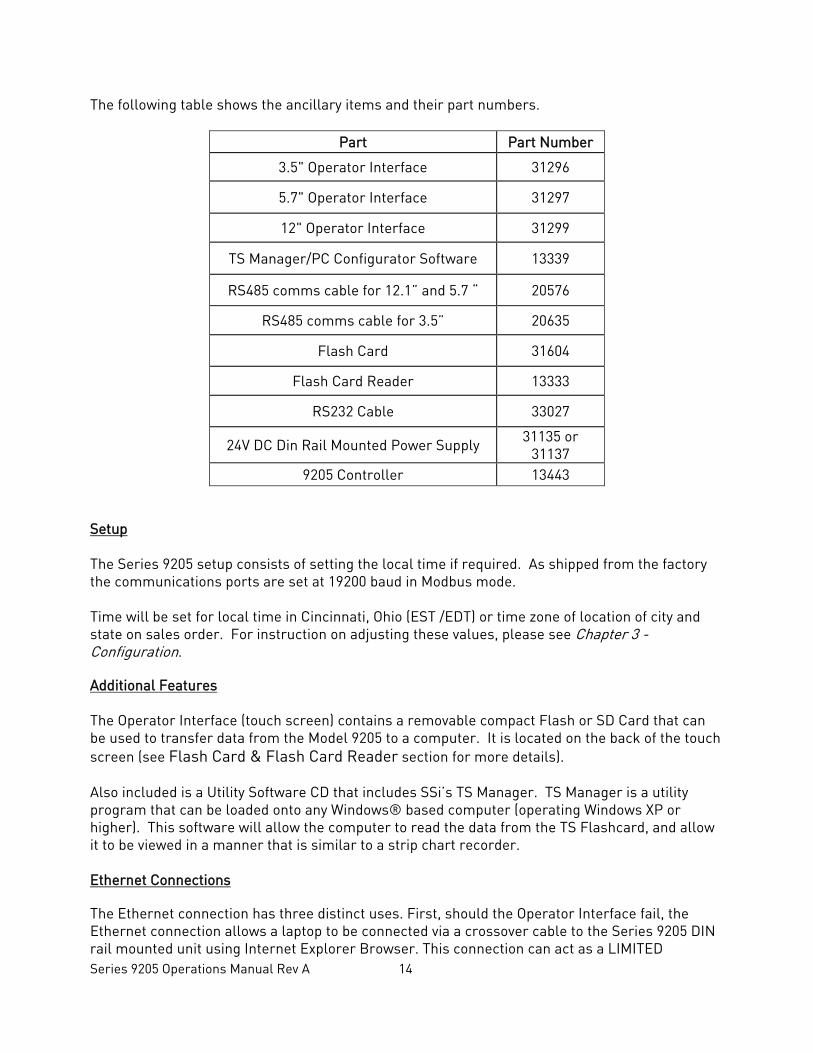
The following table shows the ancillary items and their part numbers.
Part Part Number
3.5" Operator Interface 31296
5.7" Operator Interface 31297
12" Operator Interface 31299
TS Manager/PC Configurator Software 13339
RS485 comms cable for 12.1” and 5.7 “ 20576
RS485 comms cable for 3.5” 20635
Flash Card 31604
Flash Card Reader 13333
RS232 Cable 33027
24V DC Din Rail Mounted Power Supply 31135 or 31137
9205 Controller 13443 Setup The Series 9205 setup consists of setting the local time if required. As shipped from the factory the communications ports are set at 19200 baud in Modbus mode.
Time will be set for local time in Cincinnati, Ohio (EST /EDT) or time zone of location of city and state on sales order. For instruction on adjusting these values, please see Chapter 3 - Configuration. Additional Features The Operator Interface (touch screen) contains a removable compact Flash or SD Card that can be used to transfer data from the Model 9205 to a computer. It is located on the back of the touch screen (see Flash Card & Flash Card Reader section for more details).
Also included is a Utility Software CD that includes SSi’s TS Manager. TS Manager is a utility program that can be loaded onto any Windows® based computer (operating Windows XP or higher). This software will allow the computer to read the data from the TS Flashcard, and allow it to be viewed in a manner that is similar to a strip chart recorder. Ethernet Connections The Ethernet connection has three distinct uses. First, should the Operator Interface fail, the Ethernet connection allows a laptop to be connected via a crossover cable to the Series 9205 DIN rail mounted unit using Internet Explorer Browser. This connection can act as a LIMITED
Series 9205 Operations Manual Rev A 15
!
FUNCTION “operator interface” until the Operator Interface can be repaired or replaced. The laptop needs to be operating a Windows XP or higher with Internet Explorer. The default IP address is 192.168.0.200. If you are experiencing problems please call (513) 772-0060 and talk with our computer communications personnel. Secondly, the Ethernet port can be used for communications to a SCADA software package. Call us at (513) 772-0060 if you are interested in this option. The third use for the Ethernet Port is the primary communications connection for the Configurator 2.0 Software. Instrument Start-up On power-up, the Operator Interface will display a Microsoft Windows desktop screen for a few seconds and then switch to the default Status screen. Flash Card & Flash Card Reader Never remove the flash card when the Operator Interface is “ON”. To properly shut down the Operator Interface, press the Menu button on the default status screen. Once the menu has been displayed, select the Shutdown option. At the prompt, press Yes to shut down the Operator Interface. See the Chapter 2 - CONFIGURATION section for information on navigating and using the menu system. This will display a conventional Microsoft Windows screen. Sliding the black switch to the OFF position (located directly over the green power connector, on the back of the Operator Interface) or removing the 24VDC plug will turn off the power to the Operator Interface. Once the Operator Interface is turned off, remove the compact flash card cover at the top or side of the display unit, exposing the card. Press the black release button or press card in to eject, and the card will pop out of the slot. To replace the flash card, simply return the card to the slot making sure that the release button is in its UP position, and replace the flash card cover to its proper position. To restore power to the unit, move the black switch to the right or ON position or connect plug. Operator Interface Screen Saver The Operator Interface has a default screen saver. It automatically “blanks” the screen after ten (10) minutes of non-activity. To disengage the screen saver, simply touch the screen and it will re-appear. Default Status Screen
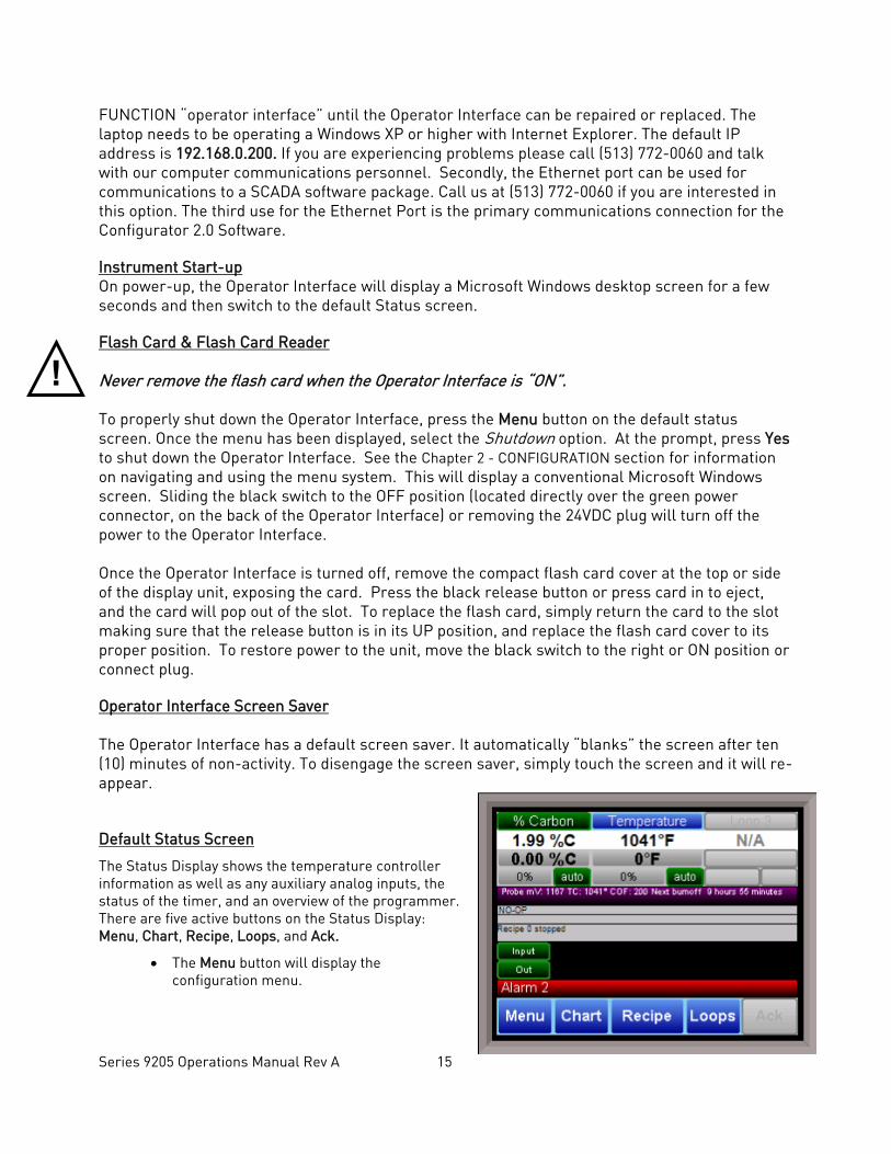
The Status Display shows the temperature controller information as well as any auxiliary analog inputs, the status of the timer, and an overview of the programmer. There are five active buttons on the Status Display: Menu, Chart, Recipe, Loops, and Ack.
• The Menu button will display the configuration menu.
Series 9205 Operations Manual Rev A 16
• The Chart button will display the video recorder screen. Use of the Chart Display is explained below.
• The Recipe button will switch to the Program Display. This is a companion display to the status screen and is described below.
• The Loops button will display the main control loop, Temperature, as well as the timer status and any auxiliary analog inputs.
• The Ack (Alarm Acknowledge) button is used to acknowledge an alarm. The alarm message is displayed directly under the recipe display. Is this only present when an alarm is going off. This button only acknowledges 9205 alarms and does not acknowledge any PLC alarms.
When the quench timer is running, the ACK button is replaced with a quench button. This quench button is used to adjust the quench timer time remaining. In the purple status bar, the quench time remaining is displayed.
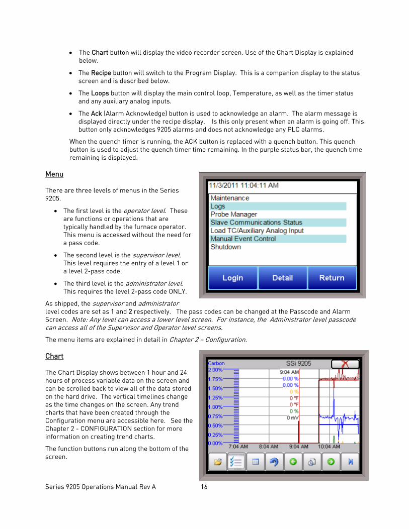
Menu There are three levels of menus in the Series 9205.
• The first level is the operator level. These are functions or operations that are typically handled by the furnace operator. This menu is accessed without the need for a pass code.
• The second level is the supervisor level. This level requires the entry of a level 1 or a level 2-pass code.
• The third level is the administrator level. This requires the level 2-pass code ONLY.
As shipped, the supervisor and administrator level codes are set as 1 and 2 respectively. The pass codes can be changed at the Passcode and Alarm Screen. Note: Any level can access a lower level screen. For instance, the Administrator level passcode can access all of the Supervisor and Operator level screens.
The menu items are explained in detail in Chapter 2 – Configuration. Chart The Chart Display shows between 1 hour and 24 hours of process variable data on the screen and can be scrolled back to view all of the data stored on the hard drive. The vertical timelines change as the time changes on the screen. Any trend charts that have been created through the Configuration menu are accessible here. See the Chapter 2 - CONFIGURATION section for more information on creating trend charts.
The function buttons run along the bottom of the screen.
Series 9205 Operations Manual Rev A 17
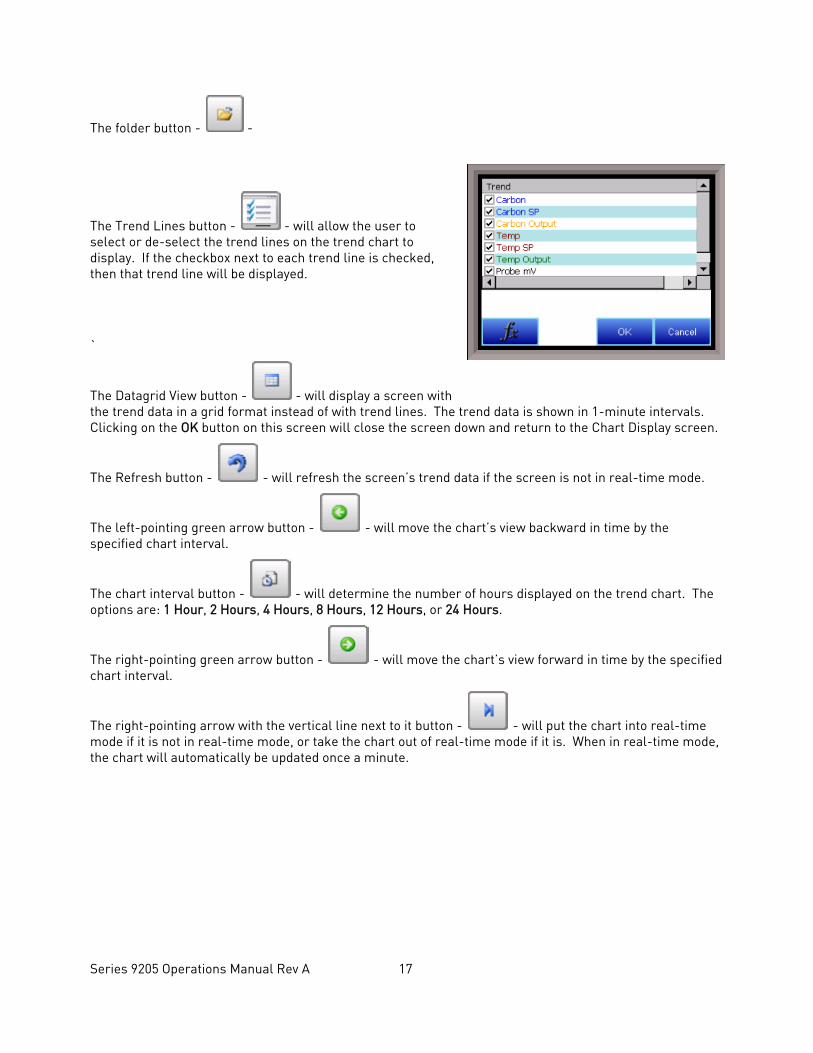
The folder button - -
The Trend Lines button - - will allow the user to select or de-select the trend lines on the trend chart to display. If the checkbox next to each trend line is checked, then that trend line will be displayed.
`
The Datagrid View button - - will display a screen with the trend data in a grid format instead of with trend lines. The trend data is shown in 1-minute intervals. Clicking on the OK button on this screen will close the screen down and return to the Chart Display screen.
The Refresh button - - will refresh the screen’s trend data if the screen is not in real-time mode.
The left-pointing green arrow button - - will move the chart’s view backward in time by the specified chart interval.
The chart interval button - - will determine the number of hours displayed on the trend chart. The options are: 1 Hour, 2 Hours, 4 Hours, 8 Hours, 12 Hours, or 24 Hours.
The right-pointing green arrow button - - will move the chart’s view forward in time by the specified chart interval.
The right-pointing arrow with the vertical line next to it button - - will put the chart into real-time mode if it is not in real-time mode, or take the chart out of real-time mode if it is. When in real-time mode, the chart will automatically be updated once a minute.
Series 9205 Operations Manual Rev A 18
Chart Sub Menu
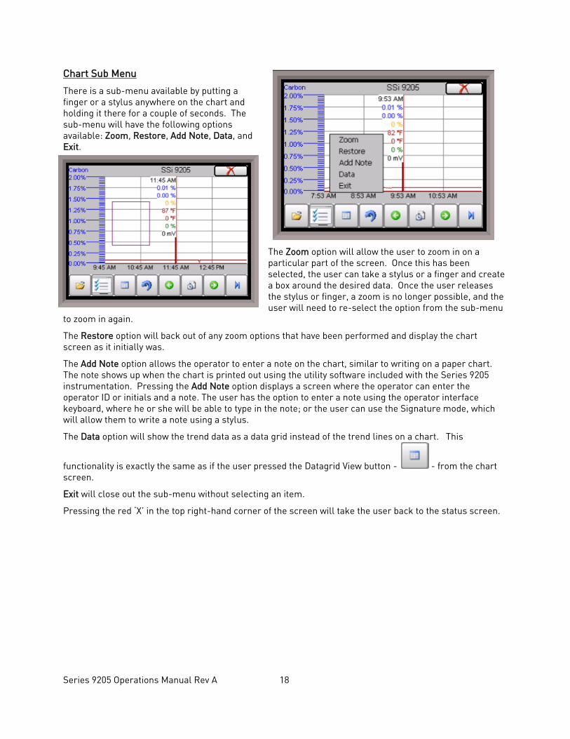
There is a sub-menu available by putting a finger or a stylus anywhere on the chart and holding it there for a couple of seconds. The sub-menu will have the following options available: Zoom, Restore, Add Note, Data, and Exit.
The Zoom option will allow the user to zoom in on a particular part of the screen. Once this has been selected, the user can take a stylus or a finger and create a box around the desired data. Once the user releases the stylus or finger, a zoom is no longer possible, and the user will need to re-select the option from the sub-menu
to zoom in again.
The Restore option will back out of any zoom options that have been performed and display the chart screen as it initially was.
The Add Note option allows the operator to enter a note on the chart, similar to writing on a paper chart. The note shows up when the chart is printed out using the utility software included with the Series 9205 instrumentation. Pressing the Add Note option displays a screen where the operator can enter the operator ID or initials and a note. The user has the option to enter a note using the operator interface keyboard, where he or she will be able to type in the note; or the user can use the Signature mode, which will allow them to write a note using a stylus.
The Data option will show the trend data as a data grid instead of the trend lines on a chart. This
functionality is exactly the same as if the user pressed the Datagrid View button - - from the chart screen.
Exit will close out the sub-menu without selecting an item.
Pressing the red ‘X’ in the top right-hand corner of the screen will take the user back to the status screen.
Series 9205 Operations Manual Rev A 19
Recipe
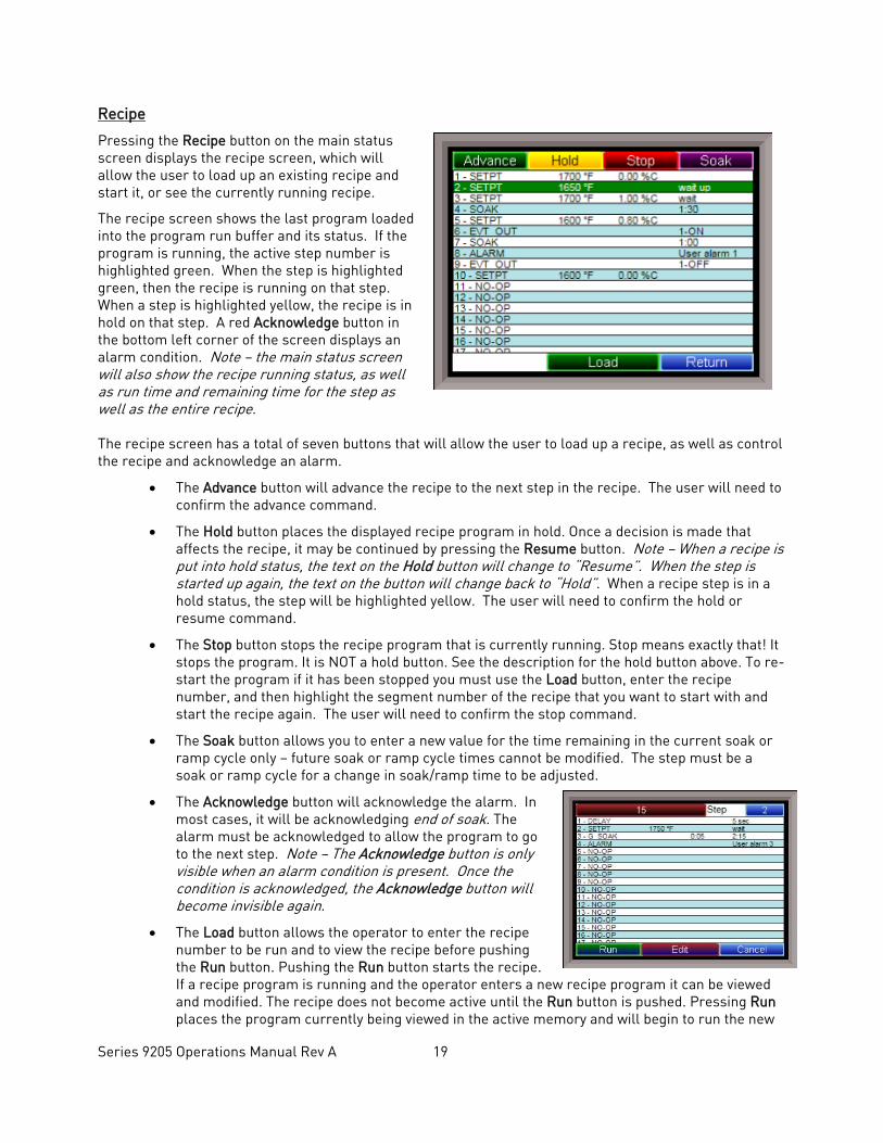
Pressing the Recipe button on the main status screen displays the recipe screen, which will allow the user to load up an existing recipe and start it, or see the currently running recipe.
The recipe screen shows the last program loaded into the program run buffer and its status. If the program is running, the active step number is highlighted green. When the step is highlighted green, then the recipe is running on that step. When a step is highlighted yellow, the recipe is in hold on that step. A red Acknowledge button in the bottom left corner of the screen displays an alarm condition. Note – the main status screen will also show the recipe running status, as well as run time and remaining time for the step as well as the entire recipe.
The recipe screen has a total of seven buttons that will allow the user to load up a recipe, as well as control the recipe and acknowledge an alarm.
• The Advance button will advance the recipe to the next step in the recipe. The user will need to confirm the advance command.
• The Hold button places the displayed recipe program in hold. Once a decision is made that affects the recipe, it may be continued by pressing the Resume button. Note – When a recipe is put into hold status, the text on the Hold button will change to “Resume”. When the step is started up again, the text on the button will change back to “Hold”. When a recipe step is in a hold status, the step will be highlighted yellow. The user will need to confirm the hold or resume command.
• The Stop button stops the recipe program that is currently running. Stop means exactly that! It stops the program. It is NOT a hold button. See the description for the hold button above. To re-start the program if it has been stopped you must use the Load button, enter the recipe number, and then highlight the segment number of the recipe that you want to start with and start the recipe again. The user will need to confirm the stop command.
• The Soak button allows you to enter a new value for the time remaining in the current soak or ramp cycle only – future soak or ramp cycle times cannot be modified. The step must be a soak or ramp cycle for a change in soak/ramp time to be adjusted.
• The Acknowledge button will acknowledge the alarm. In most cases, it will be acknowledging end of soak. The alarm must be acknowledged to allow the program to go to the next step. Note – The Acknowledge button is only visible when an alarm condition is present. Once the condition is acknowledged, the Acknowledge button will become invisible again.
• The Load button allows the operator to enter the recipe number to be run and to view the recipe before pushing the Run button. Pushing the Run button starts the recipe. If a recipe program is running and the operator enters a new recipe program it can be viewed and modified. The recipe does not become active until the Run button is pushed. Pressing Run places the program currently being viewed in the active memory and will begin to run the new
Series 9205 Operations Manual Rev A 20
recipe. To select the recipe to view or edit, click on the recipe number button in the top left corner of the screen. This will display a screen where the user will be able to load up a valid recipe (range 1 – 300). The program can be started in any step by clicking on the step number button next to the “Step” text and entering the new step number (range 1 – 24), and then pressing the Run key.
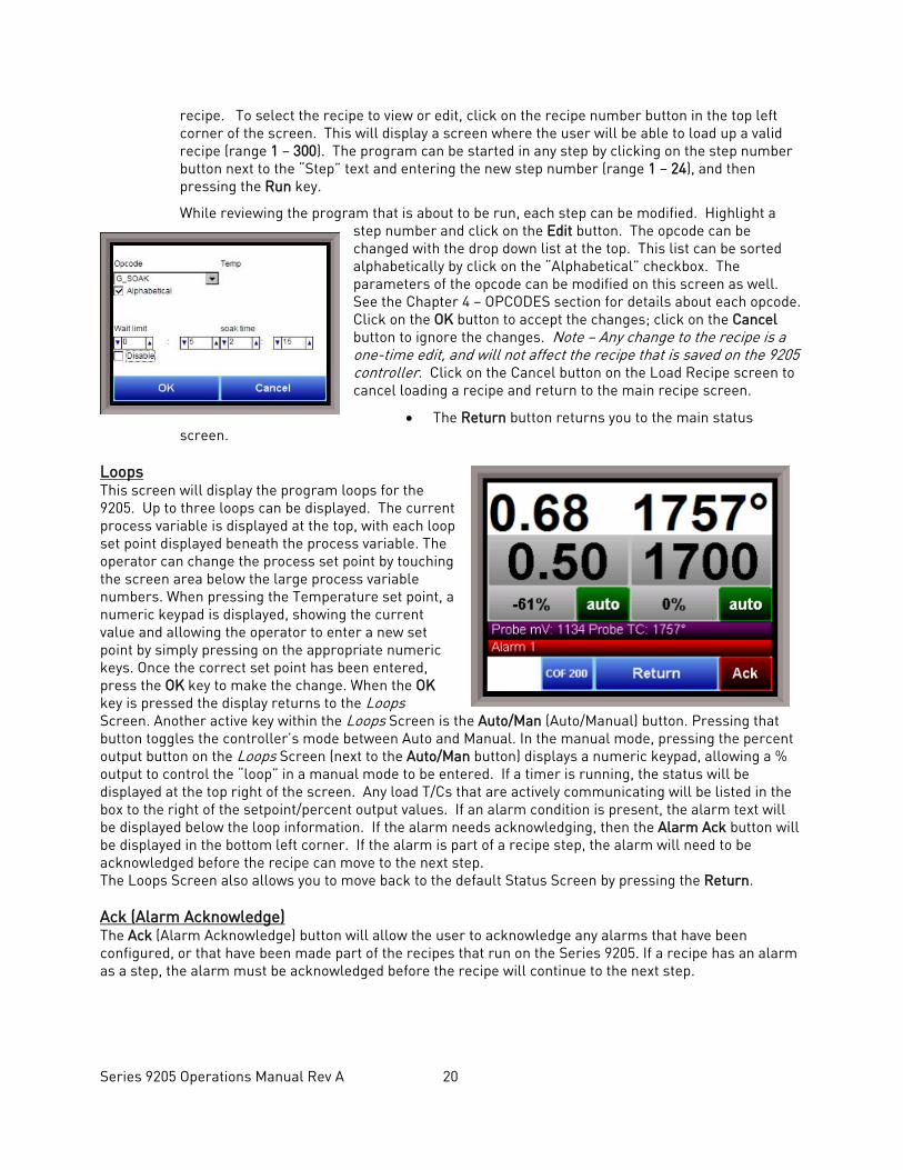
While reviewing the program that is about to be run, each step can be modified. Highlight a step number and click on the Edit button. The opcode can be changed with the drop down list at the top. This list can be sorted alphabetically by click on the “Alphabetical” checkbox. The parameters of the opcode can be modified on this screen as well. See the Chapter 4 – OPCODES section for details about each opcode. Click on the OK button to accept the changes; click on the Cancel button to ignore the changes. Note – Any change to the recipe is a one-time edit, and will not affect the recipe that is saved on the 9205 controller. Click on the Cancel button on the Load Recipe screen to cancel loading a recipe and return to the main recipe screen.
• The Return button returns you to the main status screen.
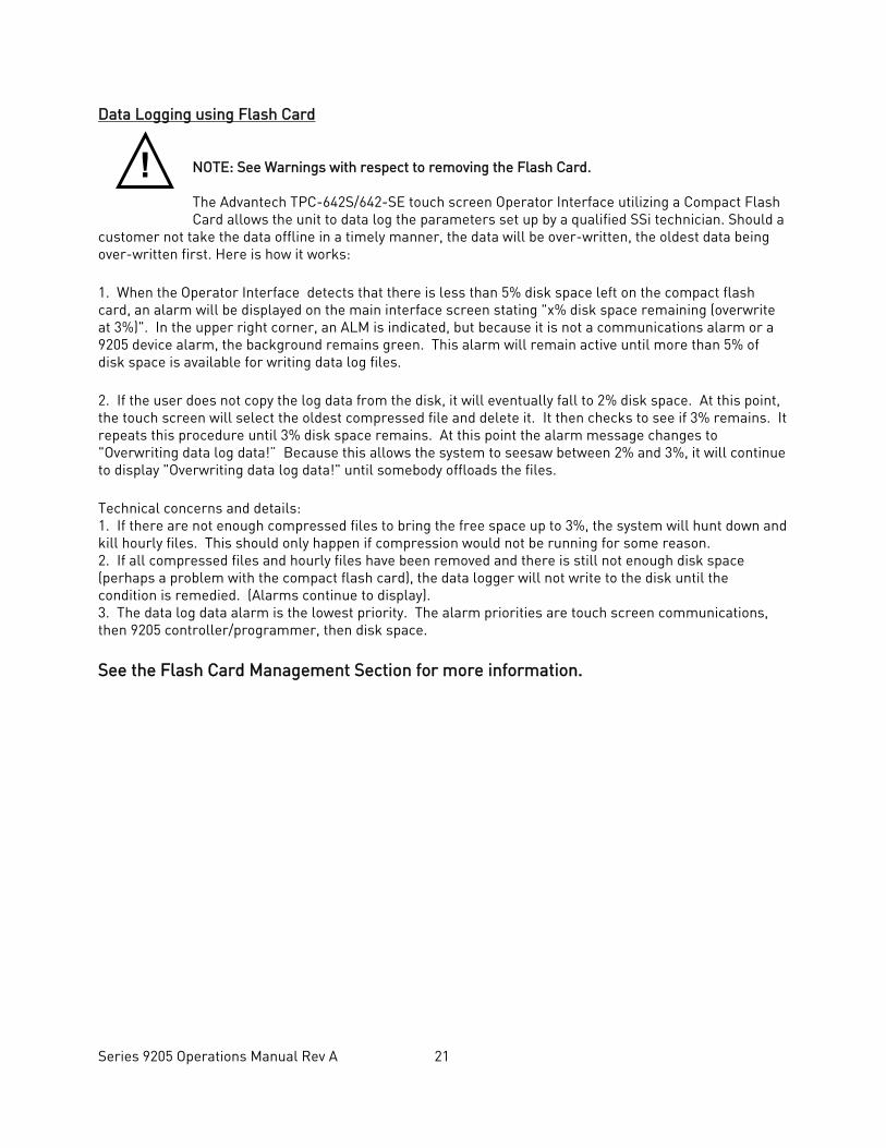
Loops This screen will display the program loops for the 9205. Up to three loops can be displayed. The current process variable is displayed at the top, with each loop set point displayed beneath the process variable. The operator can change the process set point by touching the screen area below the large process variable numbers. When pressing the Temperature set point, a numeric keypad is displayed, showing the current value and allowing the operator to enter a new set point by simply pressing on the appropriate numeric keys. Once the correct set point has been entered, press the OK key to make the change. When the OK key is pressed the display returns to the Loops Screen. Another active key within the Loops Screen is the Auto/Man (Auto/Manual) button. Pressing that button toggles the controller’s mode between Auto and Manual. In the manual mode, pressing the percent output button on the Loops Screen (next to the Auto/Man button) displays a numeric keypad, allowing a % output to control the “loop” in a manual mode to be entered. If a timer is running, the status will be displayed at the top right of the screen. Any load T/Cs that are actively communicating will be listed in the box to the right of the setpoint/percent output values. If an alarm condition is present, the alarm text will be displayed below the loop information. If the alarm needs acknowledging, then the Alarm Ack button will be displayed in the bottom left corner. If the alarm is part of a recipe step, the alarm will need to be acknowledged before the recipe can move to the next step. The Loops Screen also allows you to move back to the default Status Screen by pressing the Return. Ack (Alarm Acknowledge) The Ack (Alarm Acknowledge) button will allow the user to acknowledge any alarms that have been configured, or that have been made part of the recipes that run on the Series 9205. If a recipe has an alarm as a step, the alarm must be acknowledged before the recipe will continue to the next step.
Series 9205 Operations Manual Rev A 21
Data Logging using Flash Card NOTE: See Warnings with respect to removing the Flash Card. The Advantech TPC-642S/642-SE touch screen Operator Interface utilizing a Compact Flash Card allows the unit to data log the parameters set up by a qualified SSi technician. Should a
customer not take the data offline in a timely manner, the data will be over-written, the oldest data being over-written first. Here is how it works: 1. When the Operator Interface detects that there is less than 5% disk space left on the compact flash card, an alarm will be displayed on the main interface screen stating "x% disk space remaining (overwrite at 3%)". In the upper right corner, an ALM is indicated, but because it is not a communications alarm or a 9205 device alarm, the background remains green. This alarm will remain active until more than 5% of disk space is available for writing data log files. 2. If the user does not copy the log data from the disk, it will eventually fall to 2% disk space. At this point, the touch screen will select the oldest compressed file and delete it. It then checks to see if 3% remains. It repeats this procedure until 3% disk space remains. At this point the alarm message changes to "Overwriting data log data!” Because this allows the system to seesaw between 2% and 3%, it will continue to display "Overwriting data log data!" until somebody offloads the files. Technical concerns and details: 1. If there are not enough compressed files to bring the free space up to 3%, the system will hunt down and kill hourly files. This should only happen if compression would not be running for some reason. 2. If all compressed files and hourly files have been removed and there is still not enough disk space (perhaps a problem with the compact flash card), the data logger will not write to the disk until the condition is remedied. (Alarms continue to display). 3. The data log data alarm is the lowest priority. The alarm priorities are touch screen communications, then 9205 controller/programmer, then disk space. See the Flash Card Management Section for more information.
!
Series 9205 Operations Manual Rev A 22
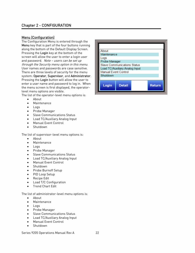
Chapter 2 - CONFIGURATION Menu (Configuration) The Configuration Menu is entered through the Menu key that is part of the four buttons running along the bottom of the Default Display Screen. Pressing the Login key at the bottom of the screen will allow the user to enter a login user and password. Note – users can be set up through the Security menu option in this menu. User names and passwords are case sensitive. There are three levels of security for the menu system: Operator, Supervisor, and Administrator. Pressing the Login button will allow the user to enter a user name and password to log in. When the menu screen is first displayed, the operator-level menu options are visible. The list of the operator-level menu options is:
• About • Maintenance • Logs • Probe Manager • Slave Communications Status • Load TC/Auxiliary Analog Input • Manual Event Control • Shutdown
The list of supervisor-level menu options is:
• About • Maintenance • Logs • Probe Manager • Slave Communications Status • Load TC/Auxiliary Analog Input • Manual Event Control • Shutdown • Probe Burnoff Setup • PID Loop Setup • Recipe Edit • Load T/C Configuration • Trend Chart Edit
The list of administrator-level menu options is:
• About • Maintenance • Logs • Probe Manager • Slave Communications Status • Load TC/Auxiliary Analog Input • Manual Event Control • Shutdown

Series 9205 Operations Manual Rev A 23
• Probe Burnoff Setup • PID Loop Setup • Recipe Edit • Load T/C Configuration • Trend Chart Edit • Communications Setup • Slave Instrument Setup • Zone Assignments • Furnace Setup • Default Wait Limits • Alarm Setup • Thermocouple Check • Relay Assignments • Analog Input Setup • Analog Output Setup • Alarm Polarity • Redundant TC Setup • Event Hold/Reset • Security • Curve Entry • Alternate PID Setup • Aux Analog Input Setup • Calibration • Configuration • A/I Module Offset Correction • Aux Setpoint Configuration • T/C Extension Correction Curves • Generic Instrument Setup • DF1 Configuration • Tuning Assistant • PLC Data Matching • Analog Input Correction Curves • Instrument Calculation
The SSi code of the day can also be used to log in to the menu system. No user name will need to be entered when entering this code. Currently, the menu list is identical to the administrator-level list. The SSi code of the day is typically used for in-house configuration prior to shipment. The code can only be provided by Super Systems at (513) 772-0060. To select any of the menu options, highlight that item by clicking on it, and click on the Detail button. The Return button will return the user to the default display screen.
Series 9205 Operations Manual Rev A 24
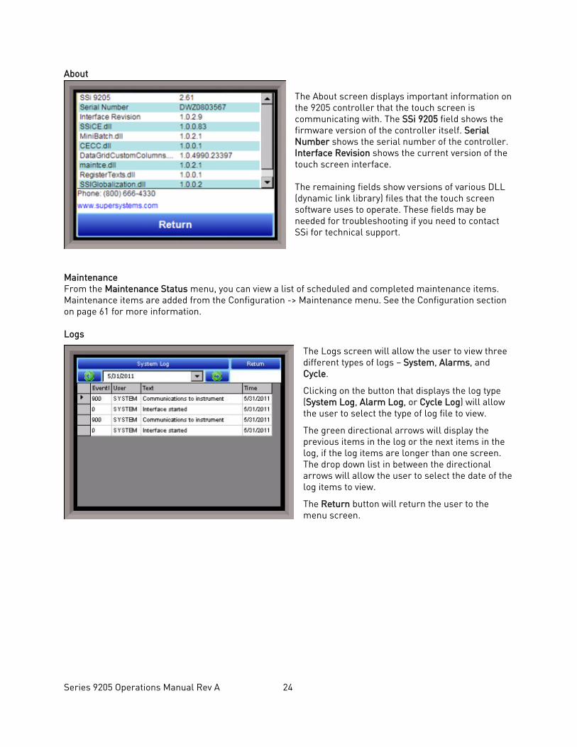
About The About screen displays important information on the 9205 controller that the touch screen is communicating with. The SSi 9205 field shows the firmware version of the controller itself. Serial Number shows the serial number of the controller. Interface Revision shows the current version of the touch screen interface. The remaining fields show versions of various DLL (dynamic link library) files that the touch screen software uses to operate. These fields may be needed for troubleshooting if you need to contact SSi for technical support.
Maintenance From the Maintenance Status menu, you can view a list of scheduled and completed maintenance items. Maintenance items are added from the Configuration -> Maintenance menu. See the Configuration section on page 61 for more information. Logs
The Logs screen will allow the user to view three different types of logs – System, Alarms, and Cycle.
Clicking on the button that displays the log type (System Log, Alarm Log, or Cycle Log) will allow the user to select the type of log file to view.
The green directional arrows will display the previous items in the log or the next items in the log, if the log items are longer than one screen. The drop down list in between the directional arrows will allow the user to select the date of the log items to view.
The Return button will return the user to the menu screen.
Series 9205 Operations Manual Rev A 25
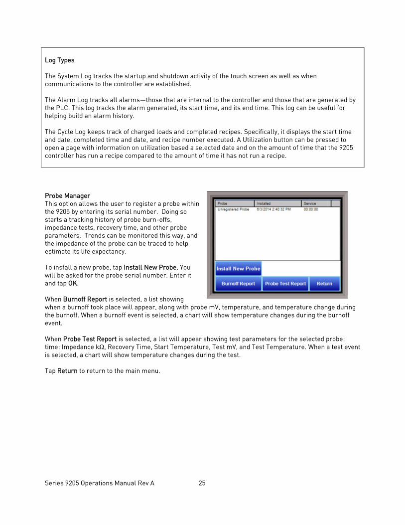
Log Types The System Log tracks the startup and shutdown activity of the touch screen as well as when communications to the controller are established. The Alarm Log tracks all alarms—those that are internal to the controller and those that are generated by the PLC. This log tracks the alarm generated, its start time, and its end time. This log can be useful for helping build an alarm history. The Cycle Log keeps track of charged loads and completed recipes. Specifically, it displays the start time and date, completed time and date, and recipe number executed. A Utilization button can be pressed to open a page with information on utilization based a selected date and on the amount of time that the 9205 controller has run a recipe compared to the amount of time it has not run a recipe. Probe Manager This option allows the user to register a probe within the 9205 by entering its serial number. Doing so starts a tracking history of probe burn-offs, impedance tests, recovery time, and other probe parameters. Trends can be monitored this way, and the impedance of the probe can be traced to help estimate its life expectancy. To install a new probe, tap Install New Probe. You will be asked for the probe serial number. Enter it and tap OK. When Burnoff Report is selected, a list showing when a burnoff took place will appear, along with probe mV, temperature, and temperature change during the burnoff. When a burnoff event is selected, a chart will show temperature changes during the burnoff event. When Probe Test Report is selected, a list will appear showing test parameters for the selected probe: time: Impedance kΩ, Recovery Time, Start Temperature, Test mV, and Test Temperature. When a test event is selected, a chart will show temperature changes during the test. Tap Return to return to the main menu.
Series 9205 Operations Manual Rev A 26
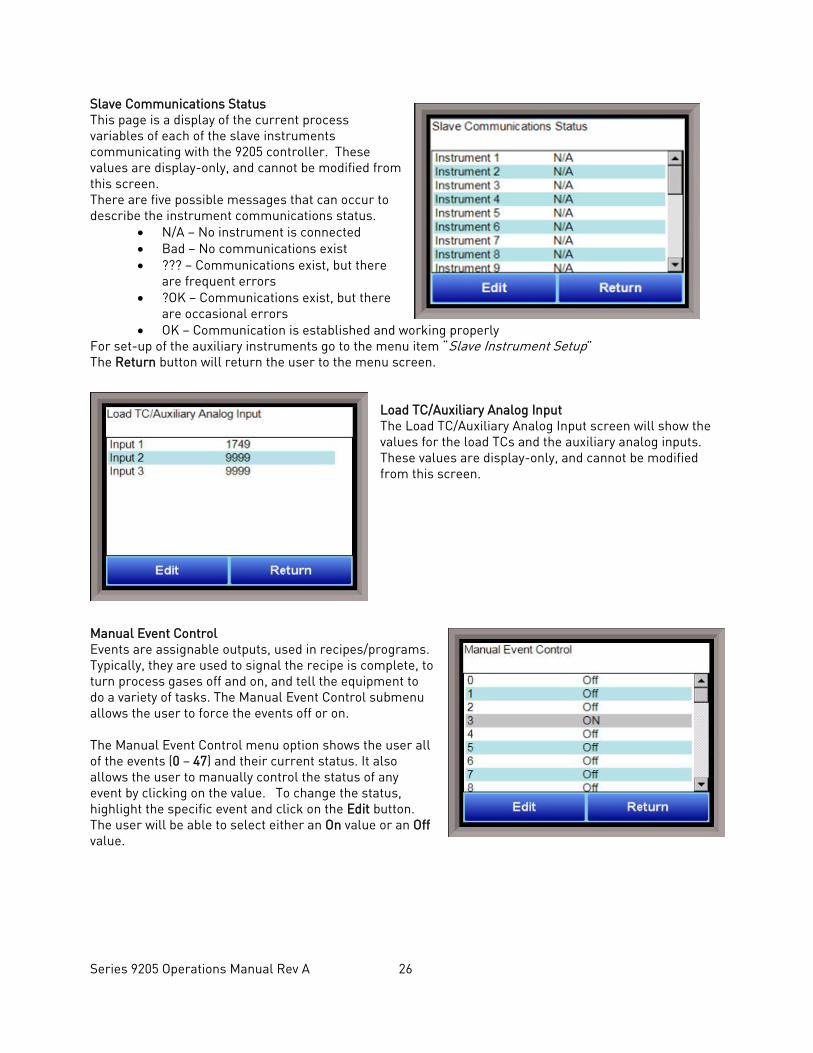
Slave Communications Status This page is a display of the current process variables of each of the slave instruments communicating with the 9205 controller. These values are display-only, and cannot be modified from this screen. There are five possible messages that can occur to describe the instrument communications status.
• N/A – No instrument is connected • Bad – No communications exist • ??? – Communications exist, but there
are frequent errors • ?OK – Communications exist, but there
are occasional errors • OK – Communication is established and working properly
For set-up of the auxiliary instruments go to the menu item “Slave Instrument Setup” The Return button will return the user to the menu screen.
Load TC/Auxiliary Analog Input The Load TC/Auxiliary Analog Input screen will show the values for the load TCs and the auxiliary analog inputs. These values are display-only, and cannot be modified from this screen.
Manual Event Control Events are assignable outputs, used in recipes/programs. Typically, they are used to signal the recipe is complete, to turn process gases off and on, and tell the equipment to do a variety of tasks. The Manual Event Control submenu allows the user to force the events off or on. The Manual Event Control menu option shows the user all of the events (0 – 47) and their current status. It also allows the user to manually control the status of any event by clicking on the value. To change the status, highlight the specific event and click on the Edit button. The user will be able to select either an On value or an Off value.
Series 9205 Operations Manual Rev A 27
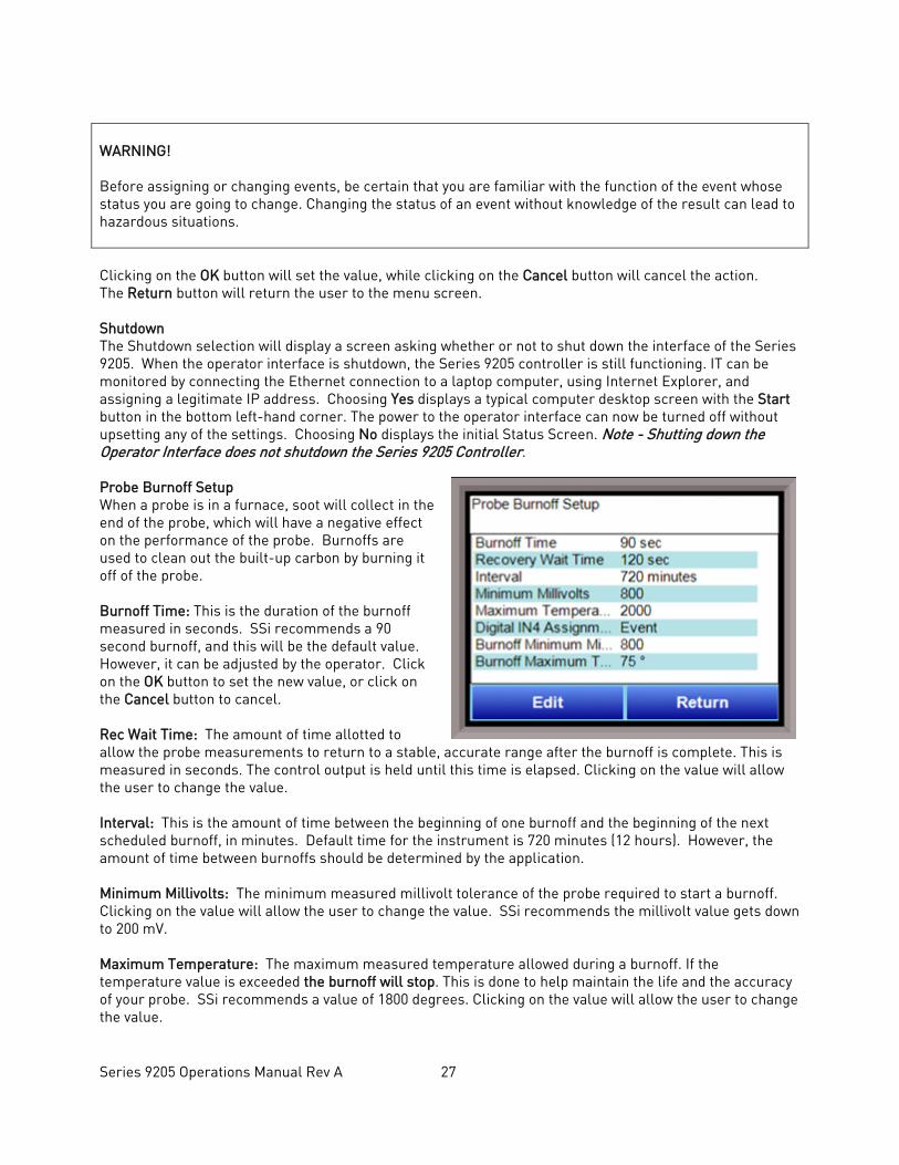
WARNING! Before assigning or changing events, be certain that you are familiar with the function of the event whose status you are going to change. Changing the status of an event without knowledge of the result can lead to hazardous situations. Clicking on the OK button will set the value, while clicking on the Cancel button will cancel the action. The Return button will return the user to the menu screen. Shutdown The Shutdown selection will display a screen asking whether or not to shut down the interface of the Series 9205. When the operator interface is shutdown, the Series 9205 controller is still functioning. IT can be monitored by connecting the Ethernet connection to a laptop computer, using Internet Explorer, and assigning a legitimate IP address. Choosing Yes displays a typical computer desktop screen with the Start button in the bottom left-hand corner. The power to the operator interface can now be turned off without upsetting any of the settings. Choosing No displays the initial Status Screen. Note - Shutting down the Operator Interface does not shutdown the Series 9205 Controller. Probe Burnoff Setup When a probe is in a furnace, soot will collect in the end of the probe, which will have a negative effect on the performance of the probe. Burnoffs are used to clean out the built-up carbon by burning it off of the probe. Burnoff Time: This is the duration of the burnoff measured in seconds. SSi recommends a 90 second burnoff, and this will be the default value. However, it can be adjusted by the operator. Click on the OK button to set the new value, or click on the Cancel button to cancel. Rec Wait Time: The amount of time allotted to allow the probe measurements to return to a stable, accurate range after the burnoff is complete. This is measured in seconds. The control output is held until this time is elapsed. Clicking on the value will allow the user to change the value. Interval: This is the amount of time between the beginning of one burnoff and the beginning of the next scheduled burnoff, in minutes. Default time for the instrument is 720 minutes (12 hours). However, the amount of time between burnoffs should be determined by the application. Minimum Millivolts: The minimum measured millivolt tolerance of the probe required to start a burnoff. Clicking on the value will allow the user to change the value. SSi recommends the millivolt value gets down to 200 mV. Maximum Temperature: The maximum measured temperature allowed during a burnoff. If the temperature value is exceeded the burnoff will stop. This is done to help maintain the life and the accuracy of your probe. SSi recommends a value of 1800 degrees. Clicking on the value will allow the user to change the value.
Series 9205 Operations Manual Rev A 28
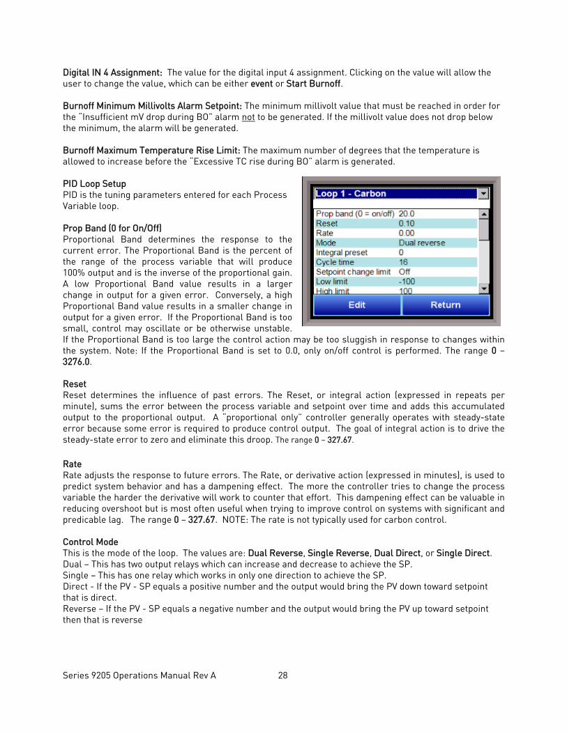
Digital IN 4 Assignment: The value for the digital input 4 assignment. Clicking on the value will allow the user to change the value, which can be either event or Start Burnoff. Burnoff Minimum Millivolts Alarm Setpoint: The minimum millivolt value that must be reached in order for the “Insufficient mV drop during BO” alarm not to be generated. If the millivolt value does not drop below the minimum, the alarm will be generated. Burnoff Maximum Temperature Rise Limit: The maximum number of degrees that the temperature is allowed to increase before the “Excessive TC rise during BO” alarm is generated. PID Loop Setup PID is the tuning parameters entered for each Process Variable loop. Prop Band (0 for On/Off) Proportional Band determines the response to the current error. The Proportional Band is the percent of the range of the process variable that will produce 100% output and is the inverse of the proportional gain. A low Proportional Band value results in a larger change in output for a given error. Conversely, a high Proportional Band value results in a smaller change in output for a given error. If the Proportional Band is too small, control may oscillate or be otherwise unstable. If the Proportional Band is too large the control action may be too sluggish in response to changes within the system. Note: If the Proportional Band is set to 0.0, only on/off control is performed. The range 0 – 3276.0. Reset Reset determines the influence of past errors. The Reset, or integral action (expressed in repeats per minute), sums the error between the process variable and setpoint over time and adds this accumulated output to the proportional output. A “proportional only” controller generally operates with steady-state error because some error is required to produce control output. The goal of integral action is to drive the steady-state error to zero and eliminate this droop. The range 0 – 327.67.
Rate Rate adjusts the response to future errors. The Rate, or derivative action (expressed in minutes), is used to predict system behavior and has a dampening effect. The more the controller tries to change the process variable the harder the derivative will work to counter that effort. This dampening effect can be valuable in reducing overshoot but is most often useful when trying to improve control on systems with significant and predicable lag. The range 0 – 327.67. NOTE: The rate is not typically used for carbon control. Control Mode This is the mode of the loop. The values are: Dual Reverse, Single Reverse, Dual Direct, or Single Direct. Dual – This has two output relays which can increase and decrease to achieve the SP. Single – This has one relay which works in only one direction to achieve the SP. Direct - If the PV - SP equals a positive number and the output would bring the PV down toward setpoint that is direct. Reverse – If the PV - SP equals a negative number and the output would bring the PV up toward setpoint then that is reverse
Series 9205 Operations Manual Rev A 29
Example: If a 12 mA output drives a 0 degree F temperature (PV) UP to a 1200 degree F temperature (SP), this would be REVERSE, and since this would take a SINGLE output from the controller, the Mode for the Temperature Loop is Single Reverse. Integral Preset This field provides an offset for the starting point for PID control, also referred to as “Load Line” or “Manual Reset”. The range is –100 to 100. Cycle Time This field is typically set to the valve travel time multiplied by 1.5. The range is 0 – 500. Setpoint Change Limit
This is a smart time feature that allows Process Loop to use PB only without Reset until the Process Variable drops below the percent output set under this category. It is used to eliminate overshoot. The Output percentage selected under this category must be above the normal operating output percentage of the furnace at heat. The options are: OFF, 80%, 70%, 60%, 50%, 40%, 30%, or 20%. Example: If the furnace runs at 40% output at heat for the maximum load, the setpoint change limit should be set to 60%. Control Low Limit This is the low limit for the loop. The range is –100 to 100. Control High Limit This is the high limit for the loop. The range is –100 to 100. 0 Setpoint Stops Control If the Setpoint is zero, then all outputs are turned off. The option is either Yes or No. IN1 high limit shuts down ctrl If input 1’s high limit is reached, then all outputs are turned off. The value can either be Yes or No. IN2 high limit shuts down ctrl If input 2’s high limit is reached, then all outputs are turned off. The value can either be Yes or No. IN3 high limit shuts down ctrl If input 3’s high limit is reached, then all outputs are turned off. The value can either be Yes or No. PID Auto Switch This is the PID auto switch field. The value can either be Yes or No. PID auto switch is a feature within the instrument that allows multiple PID Loops to be used for various temperature ranges. This feature can be extremely helpful when a single PID Loop is not accurate across a wide temperature range. The most common indication that PID auto switching may improve furnace ability is failure to pass Temperature Uniformity Surveys (TUS). In many examples, a certain PID Loop may prevent under- or over-shoot at normal operating temperatures; but produce unacceptable overshoot at lower temperature. This feature allows the user to utilize (up to) three distinct loops to obtain more accurate heating curves. In most applications, it is helpful to use the built-in Tuning Assistant feature to determine appropriate PID
Series 9205 Operations Manual Rev A 30
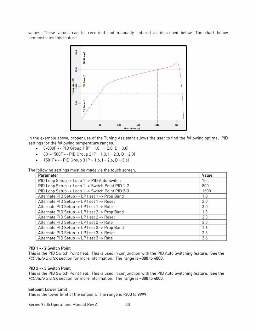
values. These values can be recorded and manually entered as described below. The chart below demonstrates this feature.
In the example above, proper use of the Tuning Assistant allows the user to find the following optimal PID settings for the following temperature ranges:
• 0-800F -> PID Group 1 (P = 1.0, I = 2.0, D = 3.0) • 801-1500F -> PID Group 2 (P = 1.3, I = 2.3, D = 2.3) • 1501F+ -> PID Group 3 (P = 1.6, I = 2.6, D = 3.6)
The following settings must be made via the touch screen: Parameter Value PID Loop Setup -> Loop 1 -> PID Auto Switch Yes PID Loop Setup -> Loop 1 -> Switch Point PID 1-2 800 PID Loop Setup -> Loop 1 -> Switch Point PID 2-3 1500 Alternate PID Setup -> LP1 set 1 -> Prop Band 1.0 Alternate PID Setup -> LP1 set 1 -> Reset 2.0 Alternate PID Setup -> LP1 set 1 -> Rate 3.0 Alternate PID Setup -> LP1 set 2 -> Prop Band 1.3 Alternate PID Setup -> LP1 set 2 -> Reset 2.3 Alternate PID Setup -> LP1 set 2 -> Rate 3.3 Alternate PID Setup -> LP1 set 3 -> Prop Band 1.6 Alternate PID Setup -> LP1 set 3 -> Reset 2.6 Alternate PID Setup -> LP1 set 3 -> Rate 3.6
PID 1 -> 2 Switch Point This is the PID Switch Point field. This is used in conjunction with the PID Auto Switching feature. See the PID Auto Switch section for more information. The range is –300 to 4000. PID 2 -> 3 Switch Point This is the PID Switch Point field. This is used in conjunction with the PID Auto Switching feature. See the PID Auto Switch section for more information. The range is –300 to 4000. Setpoint Lower Limit This is the lower limit of the setpoint. The range is –300 to 9999.
Series 9205 Operations Manual Rev A 31
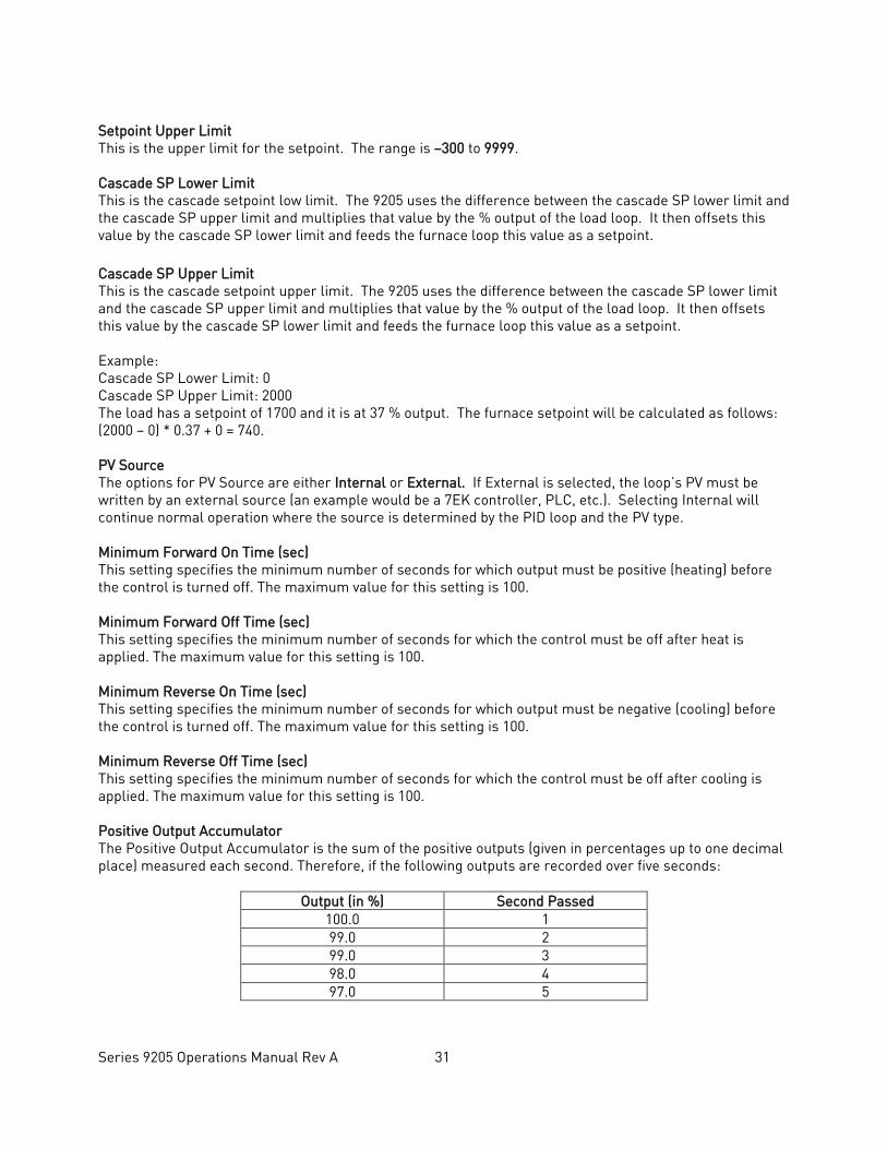
Setpoint Upper Limit This is the upper limit for the setpoint. The range is –300 to 9999. Cascade SP Lower Limit This is the cascade setpoint low limit. The 9205 uses the difference between the cascade SP lower limit and the cascade SP upper limit and multiplies that value by the % output of the load loop. It then offsets this value by the cascade SP lower limit and feeds the furnace loop this value as a setpoint. Cascade SP Upper Limit This is the cascade setpoint upper limit. The 9205 uses the difference between the cascade SP lower limit and the cascade SP upper limit and multiplies that value by the % output of the load loop. It then offsets this value by the cascade SP lower limit and feeds the furnace loop this value as a setpoint. Example: Cascade SP Lower Limit: 0 Cascade SP Upper Limit: 2000 The load has a setpoint of 1700 and it is at 37 % output. The furnace setpoint will be calculated as follows: (2000 – 0) * 0.37 + 0 = 740. PV Source The options for PV Source are either Internal or External. If External is selected, the loop’s PV must be written by an external source (an example would be a 7EK controller, PLC, etc.). Selecting Internal will continue normal operation where the source is determined by the PID loop and the PV type. Minimum Forward On Time (sec) This setting specifies the minimum number of seconds for which output must be positive (heating) before the control is turned off. The maximum value for this setting is 100. Minimum Forward Off Time (sec) This setting specifies the minimum number of seconds for which the control must be off after heat is applied. The maximum value for this setting is 100. Minimum Reverse On Time (sec) This setting specifies the minimum number of seconds for which output must be negative (cooling) before the control is turned off. The maximum value for this setting is 100. Minimum Reverse Off Time (sec) This setting specifies the minimum number of seconds for which the control must be off after cooling is applied. The maximum value for this setting is 100. Positive Output Accumulator The Positive Output Accumulator is the sum of the positive outputs (given in percentages up to one decimal place) measured each second. Therefore, if the following outputs are recorded over five seconds:
Output (in %) Second Passed 100.0 1 99.0 2 99.0 3 98.0 4 97.0 5
Series 9205 Operations Manual Rev A 32
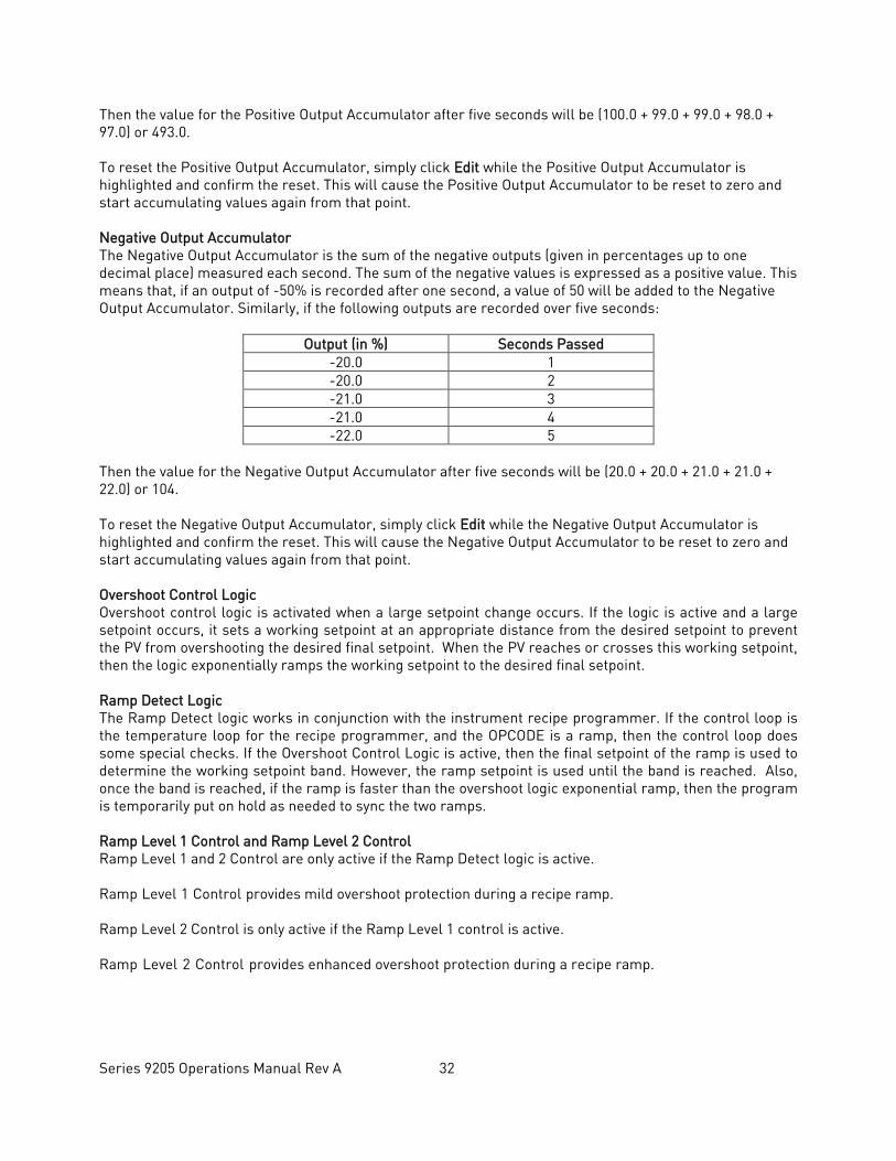
Then the value for the Positive Output Accumulator after five seconds will be (100.0 + 99.0 + 99.0 + 98.0 + 97.0) or 493.0. To reset the Positive Output Accumulator, simply click Edit while the Positive Output Accumulator is highlighted and confirm the reset. This will cause the Positive Output Accumulator to be reset to zero and start accumulating values again from that point. Negative Output Accumulator The Negative Output Accumulator is the sum of the negative outputs (given in percentages up to one decimal place) measured each second. The sum of the negative values is expressed as a positive value. This means that, if an output of -50% is recorded after one second, a value of 50 will be added to the Negative Output Accumulator. Similarly, if the following outputs are recorded over five seconds:
Output (in %) Seconds Passed -20.0 1 -20.0 2 -21.0 3 -21.0 4 -22.0 5
Then the value for the Negative Output Accumulator after five seconds will be (20.0 + 20.0 + 21.0 + 21.0 + 22.0) or 104. To reset the Negative Output Accumulator, simply click Edit while the Negative Output Accumulator is highlighted and confirm the reset. This will cause the Negative Output Accumulator to be reset to zero and start accumulating values again from that point. Overshoot Control Logic Overshoot control logic is activated when a large setpoint change occurs. If the logic is active and a large setpoint occurs, it sets a working setpoint at an appropriate distance from the desired setpoint to prevent the PV from overshooting the desired final setpoint. When the PV reaches or crosses this working setpoint, then the logic exponentially ramps the working setpoint to the desired final setpoint. Ramp Detect Logic The Ramp Detect logic works in conjunction with the instrument recipe programmer. If the control loop is the temperature loop for the recipe programmer, and the OPCODE is a ramp, then the control loop does some special checks. If the Overshoot Control Logic is active, then the final setpoint of the ramp is used to determine the working setpoint band. However, the ramp setpoint is used until the band is reached. Also, once the band is reached, if the ramp is faster than the overshoot logic exponential ramp, then the program is temporarily put on hold as needed to sync the two ramps. Ramp Level 1 Control and Ramp Level 2 Control Ramp Level 1 and 2 Control are only active if the Ramp Detect logic is active. Ramp Level 1 Control provides mild overshoot protection during a recipe ramp. Ramp Level 2 Control is only active if the Ramp Level 1 control is active. Ramp Level 2 Control provides enhanced overshoot protection during a recipe ramp.
Series 9205 Operations Manual Rev A 33
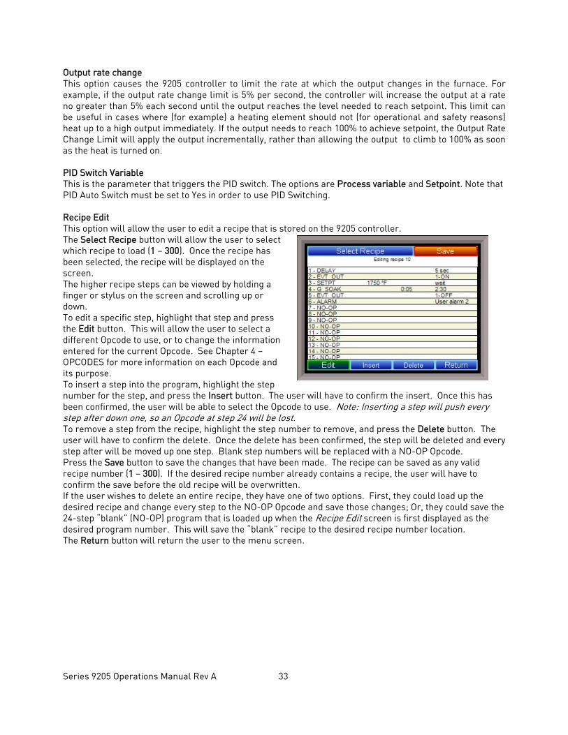
Output rate change This option causes the 9205 controller to limit the rate at which the output changes in the furnace. For example, if the output rate change limit is 5% per second, the controller will increase the output at a rate no greater than 5% each second until the output reaches the level needed to reach setpoint. This limit can be useful in cases where (for example) a heating element should not (for operational and safety reasons) heat up to a high output immediately. If the output needs to reach 100% to achieve setpoint, the Output Rate Change Limit will apply the output incrementally, rather than allowing the output to climb to 100% as soon as the heat is turned on. PID Switch Variable This is the parameter that triggers the PID switch. The options are Process variable and Setpoint. Note that PID Auto Switch must be set to Yes in order to use PID Switching. Recipe Edit This option will allow the user to edit a recipe that is stored on the 9205 controller. The Select Recipe button will allow the user to select which recipe to load (1 – 300). Once the recipe has been selected, the recipe will be displayed on the screen. The higher recipe steps can be viewed by holding a finger or stylus on the screen and scrolling up or down. To edit a specific step, highlight that step and press the Edit button. This will allow the user to select a different Opcode to use, or to change the information entered for the current Opcode. See Chapter 4 – OPCODES for more information on each Opcode and its purpose. To insert a step into the program, highlight the step number for the step, and press the Insert button. The user will have to confirm the insert. Once this has been confirmed, the user will be able to select the Opcode to use. Note: Inserting a step will push every step after down one, so an Opcode at step 24 will be lost. To remove a step from the recipe, highlight the step number to remove, and press the Delete button. The user will have to confirm the delete. Once the delete has been confirmed, the step will be deleted and every step after will be moved up one step. Blank step numbers will be replaced with a NO-OP Opcode. Press the Save button to save the changes that have been made. The recipe can be saved as any valid recipe number (1 – 300). If the desired recipe number already contains a recipe, the user will have to confirm the save before the old recipe will be overwritten. If the user wishes to delete an entire recipe, they have one of two options. First, they could load up the desired recipe and change every step to the NO-OP Opcode and save those changes; Or, they could save the 24-step “blank” (NO-OP) program that is loaded up when the Recipe Edit screen is first displayed as the desired program number. This will save the “blank” recipe to the desired recipe number location. The Return button will return the user to the menu screen.
Series 9205 Operations Manual Rev A 34
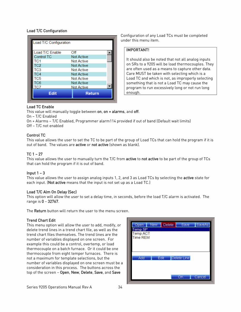
Load T/C Configuration Configuration of any Load TCs must be completed under this menu item.
IMPORTANT! It should also be noted that not all analog inputs on SRs to a 9205 will be load thermocouples. They are often used as a means to capture other data. Care MUST be taken with selecting which is a Load TC and which is not, as improperly selecting something that is not a Load TC may cause the program to run excessively long or not run long enough.
Load TC Enable This value will manually toggle between on, on + alarms, and off. On – T/C Enabled On + Alarms – T/C Enabled, Programmer alarm114 provided if out of band (Default wait limits) Off – T/C not enabled Control TC This value allows the user to set the TC to be part of the group of Load TCs that can hold the program if it is out of band. The values are active or not active (shown as blank). TC 1 – 27 This value allows the user to manually turn the T/C from active to not active to be part of the group of TCs that can hold the program if it is out of band. Input 1 – 3 This value allows the user to assign analog inputs 1, 2, and 3 as Load TCs by selecting the active state for each input. (Not active means that the input is not set up as a Load TC.) Load T/C Alm On Delay (Sec) This option will allow the user to set a delay time, in seconds, before the load T/C alarm is activated. The range is 0 – 32767. The Return button will return the user to the menu screen. Trend Chart Edit This menu option will allow the user to add, modify, or delete trend lines in a trend chart file, as well as the trend chart files themselves. The trend lines are the number of variables displayed on one screen. For example this could be a control, overtemp, or load thermocouple on a batch furnace. Or it could be one thermocouple from eight temper furnaces. There is not a maximum for template selections, but the number of variables displayed on one screen must be a consideration in this process. The buttons across the top of the screen – Open, New, Delete, Save, and Save
Series 9205 Operations Manual Rev A 35
As – deal with the trend chart files themselves, not the individual trend lines. Open will allow the user to select a trend chart file to open up to edit. New will create a new trend chart file to begin adding trend lines to. Delete will delete a specified trend chart file. Save will save all changes to the current trend chart file that have been made. Save As will allow the user to save the current trend chart file as a new file with a different name. Once a new trench chart file has been created, or one has been opened, trend lines can be added, modified, or deleted. Add will add a new trend line to the file. Edit will allow the user to edit the information for a specific trend line. Delete Line will delete the specified line from the chart file. Adding or editing a trend line will involve the following parameters: Name – the name of the input, for example “Temp ACT” which would be the actual temperature of the input. It is a good idea to shorten the names so that they still make sense, but do not take up as much space. Data – This will determine where the data is coming from. The user can click on the box to select from the list of data logged points in the 9205. Some of the points have a name, such as “Temperature” or “Temperature SP”, but others will just show the register in the 9205 that has been logged. Note that certain parameters are already setup and logged. For anything needed beyond this, you will need to contact SSi at (513) 772-0060 to get the register information. This register will need to be added to the Datalogging Setup in the Configuration menu. Min – the minimum displayed scale value on a chart. Max – the maximum displayed scale value on a chart. Expression – every input requires an expression to be calculated and displayed correctly. This is because the registers in the 9205 hold only integer values, so any value that requires a decimal point needs to be set up properly for the display. For example an expression for temperature would be x (1750 = 1750). For a value such as carbon or millivolts, the expression would be x * 0.01 (150 = 1.50) or x * 0.1 (805 = 80.5). Format – the value displayed on the chart display of the operator interface. A short custom description can be added here. For example, to display one (1) decimal point, enter a value of “#0.0”. For carbon values, enter a value of “#0.00” for 2 decimals. This would display a value like “0.81”. Entering “#.00” would display a value of “.81”. #0 or 0 will display integer values. Color – The box next to the format box will allow the user to apply a color to the trend line to differentiate it from other trend lines on the chart. Units – The type of units used for the trend. Line Width – a numeric value for the thickness of the trend line. A 1 is a thin line; A higher value = thicker line width. Sample – a number is entered here to test the expression and verify that formatting is correct. Test – Press the test button to calculate the expression with the value entered in the sample parameter. For example with an expression of x*.1 and a value of 250 entered in the sample parameter will display a 25.0. The Set button will save the values entered. The Cancel button will cancel the information and make no changes. The OK button will close the screen and prompt the user to save any changes if changes have been made. The Cancel button will close the screen and return to the menu screen.
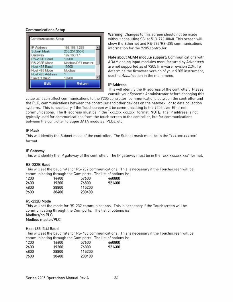
Series 9205 Operations Manual Rev A 36
Communications Setup Warning: Changes to this screen should not be made without consulting SSi at 513-772-0060. This screen will show the Ethernet and RS-232/RS-485 communications information for the 9205 controller. Note about ADAM module support: Communications with ADAM analog input modules manufactured by Advantech are not supported as of 9205 firmware revision 2.34. To determine the firmware version of your 9205 instrument, use the About option in the main menu. IP Address This will identify the IP address of the controller. Please consult your Systems Administrator before changing this
value as it can affect communications to the 9205 controller, communications between the controller and the PLC, communications between the controller and other devices on the network, or to data collection systems. This is necessary if the Touchscreen will be communicating to the 9205 over Ethernet communications. The IP address must be in the “xxx.xxx.xxx.xxx” format. NOTE: The IP address is not typically used for communications from the touch screen to the controller, but for communications between the controller to SuperDATA modules, PLCs, etc. IP Mask This will identify the Subnet mask of the controller. The Subnet mask must be in the “xxx.xxx.xxx.xxx” format. IP Gateway This will identify the IP gateway of the controller. The IP gateway must be in the “xxx.xxx.xxx.xxx” format. RS-232B Baud This will set the baud rate for RS-232 communications. This is necessary if the Touchscreen will be communicating through the Com ports. The list of options is: 1200 14400 57600 460800 2400 19200 76800 921600 4800 28800 115200 9600 38400 230400 RS-232B Mode This will set the mode for RS-232 communications. This is necessary if the Touchscreen will be communicating through the Com ports. The list of options is: Modbus/no PLC Modbus master/PLC Host 485 (3,4) Baud This will set the baud rate for RS-485 communications. This is necessary if the Touchscreen will be communicating through the Com ports. The list of options is: 1200 14400 57600 460800 2400 19200 76800 921600 4800 28800 115200 9600 38400 230400
Series 9205 Operations Manual Rev A 37
Host 485 (3,4) Mode This will set the mode for RS-485 communications. This is necessary if the Touchscreen will be communicating through the Com ports. This setting is fixed at Modbus. Host 485 Address This will set the address for RS-485 communications. This is necessary if the Touchscreen will be communicating through the Com ports. The range is 1 – 247. Slave 1 485 (5,6) Baud This will set the baud rate for Slave 1 communications. The list of options is: 1200 14400 57600 460800 2400 19200 76800 921600 4800 28800 115200 9600 38400 230400 Slave 1 485 (5,6) Mode This will set the mode for Slave 1 communications. This list of options is: Modbus Yokogawa Modbus Host Slave 2 485 (22,23) Baud This will set the baud rate for Slave 2 communications. The list of options is: 1200 14400 57600 460800 2400 19200 76800 921600 4800 28800 115200 9600 38400 230400 Slave 2 485 (22,23) Mode This will set the mode for Slave 2 communications. This list of options is: Modbus SSi Analog Input Board Yokogawa PLC Type The list of options is: Micrologix Modbus MCMmodule Modbus DF1 PLC5 DF1 Slik Passive Host 232A Baud This will set the baud rate for RS-232 communications. This is necessary if the Touchscreen will be communicating through the Com ports. The list of options is: 1200 14400 57600 460800 2400 19200 76800 921600 4800 28800 115200 9600 38400 230400 Host 232A Mode This will set the mode rate for RS-232 communications. This is necessary if the Touchscreen will be communicating through the Com ports. This setting is fixed at Modbus.
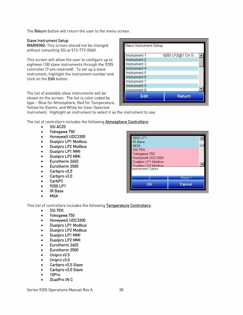
Series 9205 Operations Manual Rev A 38
The Return button will return the user to the menu screen. Slave Instrument Setup WARNING: This screen should not be changed without consulting SSi at 513-772-0060. This screen will allow the user to configure up to eighteen (18) slave instruments through the 9205 controller (7 are reserved). To set up a slave instrument, highlight the instrument number and click on the Edit button. The list of available slave instruments will be shown on the screen. The list is color coded by type – Blue for Atmosphere, Red for Temperature, Yellow for Events, and White for User-Selected Instrument. Highlight an instrument to select it as the instrument to use. The list of controllers includes the following Atmosphere Controllers:
• SSi AC20 • Yokogawa 750 • Honeywell UDC3300 • Dualpro LP1 Modbus • Dualpro LP2 Modbus • Dualpro LP1 MMI • Dualpro LP2 MMI • Eurotherm 2402 • Eurotherm 2500 • Carbpro v3.5 • Carbpro v3.0 • CarbPC • 9200 LP1 • IR Base • MGA
This list of controllers includes the following Temperature Controllers:
• SSi 7EK • Yokogawa 750 • Honeywell UDC3300 • Dualpro LP1 Modbus • Dualpro LP2 Modbus • Dualpro LP1 MMI • Dualpro LP2 MMI • Eurotherm 2402 • Eurotherm 2500 • Unipro v3.5 • Unipro v3.0 • Carbpro v3.5 Slave • Carbpro v3.0 Slave • 10Pro • DualPro IN C
Series 9205 Operations Manual Rev A 39
• 9200 LP1 • 9200 LP2 • 9200 LP3 • 9100 LP2 • Eurotherm 2704 LP1 • Eurotherm 2704 LP2 • Eurotherm 2704 LP3 • VC BASE 1 • VC BASE 2 • VC BASE 3 • VC BASE 4 • AIPC • SSi 7SL • AEC FurnaceMeter • UMC800 LP1 • SSi Quad AO1 • SSi Quad AO2 • SSi Quad AO3 • SSi Quad AO4 • Yokogawa UT350 • Yokogawa 750 Lp 2 • Yokogawa UP350 • Honeywell DCP551 • Ascon 08 • SSi X5 • SSi M4L • SSi X5/timer • SSi SPUD • SSi AIB3 • SSi H2 cell • Flow Meter Short • SSi O2 remote • SSi Dual Motor Board • SSi Smart AIB3 • O2 Block • Waukee Valvetronic +
This list of controllers includes the following Event Controllers: • SSi AC E • Yokogawa 750E • Mod Mux • Dualpro E Modbus • Dualpro E MMI • Carbpro E v3.5 • Carbpro E v3.0 • Eurotherm 2500 • SSi 8-8 • SSi 9200E • Micrologix PLC • MCM Module • PLC5 DF1 • SLC DF1
Series 9205 Operations Manual Rev A 40
User devices User 1 – 15 can also be selected. The number below the list is the address for the slave instrument. The range is 0 – 25. ** All devices on the same slave port must utilize the same protocol ** An address of zero (0) will disable the instrument** Some controllers (AC20 for example) can provide dual functions (atmosphere and events) and must have the same address assigned for both. The slave port is next to the address. The Slave port option can be: Slave 1, Slave 2, or RS-232. Some instruments may not be shown in the list of instruments. User Instruments 1 through 16 are used to set up a non-listed instrument as a slave instrument using the Generic Instrument Setup menu. The OK button will set the slave instrument, and the Cancel button will cancel the setup. The Return button will return the user to the menu screen.
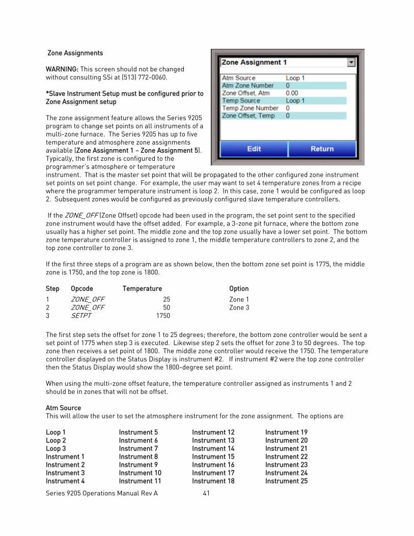
Series 9205 Operations Manual Rev A 41
Zone Assignments WARNING: This screen should not be changed without consulting SSi at (513) 772-0060. *Slave Instrument Setup must be configured prior to Zone Assignment setup The zone assignment feature allows the Series 9205 program to change set points on all instruments of a multi-zone furnace. The Series 9205 has up to five temperature and atmosphere zone assignments available (Zone Assignment 1 – Zone Assignment 5). Typically, the first zone is configured to the programmer’s atmosphere or temperature instrument. That is the master set point that will be propagated to the other configured zone instrument set points on set point change. For example, the user may want to set 4 temperature zones from a recipe where the programmer temperature instrument is loop 2. In this case, zone 1 would be configured as loop 2. Subsequent zones would be configured as previously configured slave temperature controllers. If the ZONE_OFF (Zone Offset) opcode had been used in the program, the set point sent to the specified zone instrument would have the offset added. For example, a 3-zone pit furnace, where the bottom zone usually has a higher set point. The middle zone and the top zone usually have a lower set point. The bottom zone temperature controller is assigned to zone 1, the middle temperature controllers to zone 2, and the top zone controller to zone 3. If the first three steps of a program are as shown below, then the bottom zone set point is 1775, the middle zone is 1750, and the top zone is 1800. Step Opcode Temperature Option
1 ZONE_OFF 25 Zone 1 2 ZONE_OFF 50 Zone 3 3 SETPT 1750
The first step sets the offset for zone 1 to 25 degrees; therefore, the bottom zone controller would be sent a set point of 1775 when step 3 is executed. Likewise step 2 sets the offset for zone 3 to 50 degrees. The top zone then receives a set point of 1800. The middle zone controller would receive the 1750. The temperature controller displayed on the Status Display is instrument #2. If instrument #2 were the top zone controller then the Status Display would show the 1800-degree set point. When using the multi-zone offset feature, the temperature controller assigned as instruments 1 and 2 should be in zones that will not be offset. Atm Source This will allow the user to set the atmosphere instrument for the zone assignment. The options are Loop 1 Instrument 5 Instrument 12 Instrument 19 Loop 2 Instrument 6 Instrument 13 Instrument 20 Loop 3 Instrument 7 Instrument 14 Instrument 21 Instrument 1 Instrument 8 Instrument 15 Instrument 22 Instrument 2 Instrument 9 Instrument 16 Instrument 23 Instrument 3 Instrument 10 Instrument 17 Instrument 24 Instrument 4 Instrument 11 Instrument 18 Instrument 25
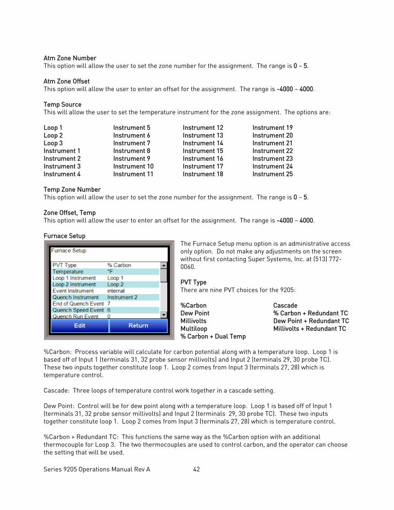
Series 9205 Operations Manual Rev A 42
Atm Zone Number This option will allow the user to set the zone number for the assignment. The range is 0 – 5. Atm Zone Offset This option will allow the user to enter an offset for the assignment. The range is -4000 – 4000. Temp Source This will allow the user to set the temperature instrument for the zone assignment. The options are: Loop 1 Instrument 5 Instrument 12 Instrument 19 Loop 2 Instrument 6 Instrument 13 Instrument 20 Loop 3 Instrument 7 Instrument 14 Instrument 21 Instrument 1 Instrument 8 Instrument 15 Instrument 22 Instrument 2 Instrument 9 Instrument 16 Instrument 23 Instrument 3 Instrument 10 Instrument 17 Instrument 24 Instrument 4 Instrument 11 Instrument 18 Instrument 25 Temp Zone Number This option will allow the user to set the zone number for the assignment. The range is 0 – 5. Zone Offset, Temp This option will allow the user to enter an offset for the assignment. The range is -4000 – 4000. Furnace Setup
The Furnace Setup menu option is an administrative access only option. Do not make any adjustments on the screen without first contacting Super Systems, Inc. at (513) 772-0060. PVT Type There are nine PVT choices for the 9205: %Carbon Cascade Dew Point % Carbon + Redundant TC Millivolts Dew Point + Redundant TC Multiloop Millivolts + Redundant TC % Carbon + Dual Temp
%Carbon: Process variable will calculate for carbon potential along with a temperature loop. Loop 1 is based off of Input 1 (terminals 31, 32 probe sensor millivolts) and Input 2 (terminals 29, 30 probe TC). These two inputs together constitute loop 1. Loop 2 comes from Input 3 (terminals 27, 28) which is temperature control. Cascade: Three loops of temperature control work together in a cascade setting. Dew Point: Control will be for dew point along with a temperature loop. Loop 1 is based off of Input 1 (terminals 31, 32 probe sensor millivolts) and Input 2 (terminals 29, 30 probe TC). These two inputs together constitute loop 1. Loop 2 comes from Input 3 (terminals 27, 28) which is temperature control. %Carbon + Redundant TC: This functions the same way as the %Carbon option with an additional thermocouple for Loop 3. The two thermocouples are used to control carbon, and the operator can choose the setting that will be used.
Series 9205 Operations Manual Rev A 43
Millivolts: Control is based off of what the millivolt reading is and also reads temperature. Dew Point + Redundant TC: This functions the same way as the Dew Point option with an additional thermocouple for Loop 3. The two thermocouples are used to control dew point, and the operator can choose the setting that will be used. Multiloop: Three loops of control can be assigned as selected. Millivolts + Redundant TC: Control is based off of the millivolt reading and also reads temperature. Loop 3 is another thermocouple. %Carbon + Dual Temp: This functions similarly to %Carbon. Input 2 is the control TC. IT is not used to calculate carbon potential with input one and to control furnace temperature. Input 3 in the third loop and is another TC. IMPORTANT: If the 9205 is controlling % Carbon or Dew Point, control will be disabled if either or both of the following are true:
• Millivolts registered by probe are below 500 mV or above 1300 mV. • Temperature registered by probe is below 900°F or above 2100°F.
Temperature Mode
This allows the operator to choose either degrees Fahrenheit or degrees Celsius for the temperature. The options are °C or °F. Pressing OK will set the choice. Loop 1 Instrument Loop 1 (typical) Instrument 5 Instrument 12 Instrument 19 Loop 2 Instrument 6 Instrument 13 Instrument 20 Loop 3 Instrument 7 Instrument 14 Instrument 21 Instrument 1 Instrument 8 Instrument 15 Instrument 22 Instrument 2 Instrument 9 Instrument 16 Instrument 23 Instrument 3 Instrument 10 Instrument 17 Instrument 24 Instrument 4 Instrument 11 Instrument 18 Instrument 25 Loop 2 Instrument Loop 1 Instrument 5 Instrument 12 Instrument 19 Loop 2 (typical) Instrument 6 Instrument 13 Instrument 20 Loop 3 Instrument 7 Instrument 14 Instrument 21 Instrument 1 Instrument 8 Instrument 15 Instrument 22 Instrument 2 Instrument 9 Instrument 16 Instrument 23 Instrument 3 Instrument 10 Instrument 17 Instrument 24 Instrument 4 Instrument 11 Instrument 18 Instrument 25 Event Instrument Allows for a slave instrument (or internal) to be the defined event control device. The types of instruments are: Internal, Instrument 1 – Instrument 25. Internal is typical. Quench Instrument Allows for slave instrument (or internal) to be the defined quench control device. This is setup in the configurator furnace setup submenu. It will send the setpoint out to whatever instrument is configured for quench. The types of instruments are: Loop 1 – Loop 3, Instrument 1 – Instrument 25.
Series 9205 Operations Manual Rev A 44
End of Quench Event Tells the programmer which event to signal end of quench (related to which relay it is assigned). The default event for this is Event 7, but it can be changed in the furnace setup menu. This event turns on for one (1) minute when the quench timer is complete. The list of possible values is: 0 – 15. Quench Speed Event Tells the programmer which event will signal the quench speed. The default event for this is event 6. This event will remain off if quench speed is set to low. It will turn on if quench timer is timing and quench speed is set to high with the QUENCH opcode. The list of possible values is: 0 – 15. Quench Run Event Tells the programmer which event will signal quench run. The default event for this is 0. This event will stay on when the quench timer is timing. The list of possible values is: 0 – 15. Date and Time This value is the current date and time on the 9205 controller only (not the local computer or the touch screen, if applicable). The time on the controller is displayed in the 24-hour format, so 8 = 8 AM, and 14 = 2 PM. Note: The date and time of the touch screen can be changed (if necessary) by selecting the date and time in the lower right corner on the touch screen, once the screen software has been shut down and the Windows™ desktop is visible. Then, at the CE screen the date and time can be changed by double taping the time in the bottom right corner and setting it, then select “apply”. For this to take effect the screen needs to be rebooted; on the older TPC 642 displays the registry needs to be saved under TPC Configuration icon, the Misc Tab and then reboot the touch screen. The date and time that is recorded on the flash card (and therefore the datalog data) is the date and time of the Advantech display, not the controller. Default Hold Time This value is the default holding time for the furnace. The range is 0 to 10000. Deviation Alarm Delay This value is the delay for the alarm if a deviation alarm is detected. The range is 0 to 10000. Name This will allow the user to give the controller a display name. PV1 Name This will allow the user to give the first process variable a display name. PV2 Name This will allow the user to give the second process variable a display name PV3 Name This will allow the user to give the third process variable a display name Clear events/end of recipe This switch will allow the user to clear the events out at the end of a recipe. The options are either no or yes. Start Quench This option will determine what event starts the quench cycle. It determines whether the quench timer starts immediately after it sees the quench opcode or if it waits for an input event If this option is set to start on an opcode, when the recipe reaches the step, it will preload the timer and start timing immediately.

Series 9205 Operations Manual Rev A 45
If it is set for an input, it will preload the timer but wait until it sees the input configured go high before it starts timing. The options are: On Recipe Opcode (QUENCH Opcode), Input 1 – Input 31. Quench Hold Event This option will determine which event will hold the quench cycle. It is used to hold the quench timer with an external device. If the input that is configured turns on then the quench timer will go into a hold mode. The list of possible values is: 0 – 15. Quench Transfer Time Configuration This option will allow the user to set what will trigger the transfer from the quench cycle. The options are: Event 2 Active Time, or Event 1 Active to Event 2 Active. Cascade Inhibit Note: This field is only applicable if the controller is in Cascade mode. This will turn cascade control on or off. When inhibit = enabled, the 9205 functions as a multi-loop controller with three control loops. The options are: enabled or disabled. PV Difference Cutback Note: This field is only applicable if the controller is in Cascade Mode. This is used with the Cascade Lower Range EOPV and Cascade Upper Range EOPV to limit the absolute % output of the furnace loop. This will turn the PV difference cutback feature on or off. The options are: enabled or disabled. Cascade Lower Range EOPV Note: This field is only applicable if the controller is in Cascade Mode. This is the cascade lower range end of PV difference. This is used with the PV Difference Cutback and Cascade Upper Range EOPV to limit the absolute % output of the furnace loop. Between the lower range EPOV and the upper range EOPV, there is a linear interpolation from 0 to the loop 2 output maximum (usually 100 %) that determines the maximum % output for the furnace loop. The range is -300 to 10000. Cascade Upper Range EOPV Note: This field is only applicable if the controller is in Cascade Mode. This is the cascade upper range end of PV difference. This is used with the Cascade Lower Range EOPV and PV Difference Cutback to limit the absolute % output of the furnace loop. Between the lower range EPOV and the upper range EOPV, there is a linear interpolation from 0 to the loop 2 output maximum (usually 100 %) that determines the maximum % output for the furnace loop. The range is -300 to 10000. Example: With the Lower EOPV set to 10 and the Upper EOPV set to 110, if the load PV is 1700 and the furnace PV is 1710, the full 100% output is available. If the load PV is 1600 and the furnace PV is 1710, the furnace output will not go above 0%. If the load PV is 1655 and the furnace PV is 1710, the maximum output for the furnace loop will be limited to 55%: (1710 – 1655)/(110-10) * (1.0). Multiloop Display
This option allows the user to decide which combination of loops will be displayed on the default status screen. The choices are: No display Loop 1, Loop 2 Loop 2, Loop 3 Loop 1 Loop 3 Loop 1, Loop 2, Loop 3 Loop 2 Loop 1, Loop 3 The Return button will return the user to the menu screen.
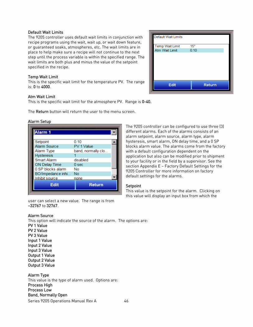
Series 9205 Operations Manual Rev A 46
Default Wait Limits The 9205 controller uses default wait limits in conjunction with recipe programs using the wait, wait up, or wait down feature, or guaranteed soaks, atmospheres, etc. The wait limits are in place to help make sure a recipe will not continue to the next step until the process variable is within the specified range. The wait limits are both plus and minus the value of the setpoint specified in the recipe. Temp Wait Limit This is the specific wait limit for the temperature PV. The range is: 0 to 4000. Atm Wait Limit This is the specific wait limit for the atmosphere PV. Range is 0-40. The Return button will return the user to the menu screen. Alarm Setup
The 9205 controller can be configured to use three (3) different alarms. Each of the alarms consists of an alarm setpoint, alarm source, alarm type, alarm hysteresis, smart alarm, ON delay time, and a 0 SP blocks alarm value. The alarms come from the factory with a default configuration dependent on the application but also can be modified prior to shipment to your facility or in the field by a supervisor. See the section Appendix E – Factory Default Settings for the 9205 Controller for more information on factory default settings for the alarms. Setpoint This value is the setpoint for the alarm. Clicking on this value will display an input box from which the
user can select a new value. The range is from –32767 to 32767. Alarm Source This option will indicate the source of the alarm. The options are: PV 1 Value PV 2 Value PV 3 Value Input 1 Value Input 2 Value Input 3 Value Output 1 Value Output 2 Value Output 3 Value Alarm Type This value is the type of alarm used. Options are: Process High Process Low Band, Normally Open
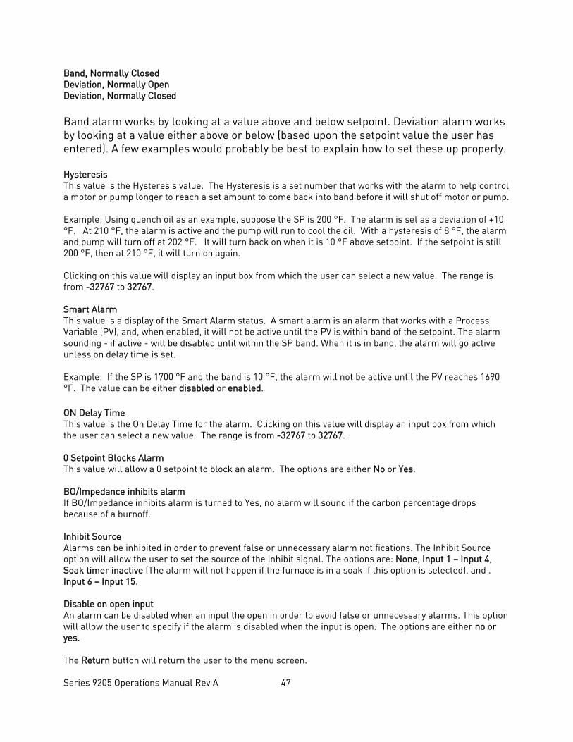
Series 9205 Operations Manual Rev A 47
Band, Normally Closed Deviation, Normally Open Deviation, Normally Closed Band alarm works by looking at a value above and below setpoint. Deviation alarm works by looking at a value either above or below (based upon the setpoint value the user has entered). A few examples would probably be best to explain how to set these up properly. Hysteresis This value is the Hysteresis value. The Hysteresis is a set number that works with the alarm to help control a motor or pump longer to reach a set amount to come back into band before it will shut off motor or pump. Example: Using quench oil as an example, suppose the SP is 200 °F. The alarm is set as a deviation of +10 °F. At 210 °F, the alarm is active and the pump will run to cool the oil. With a hysteresis of 8 °F, the alarm and pump will turn off at 202 °F. It will turn back on when it is 10 °F above setpoint. If the setpoint is still 200 °F, then at 210 °F, it will turn on again. Clicking on this value will display an input box from which the user can select a new value. The range is from -32767 to 32767. Smart Alarm This value is a display of the Smart Alarm status. A smart alarm is an alarm that works with a Process Variable (PV), and, when enabled, it will not be active until the PV is within band of the setpoint. The alarm sounding - if active - will be disabled until within the SP band. When it is in band, the alarm will go active unless on delay time is set. Example: If the SP is 1700 °F and the band is 10 °F, the alarm will not be active until the PV reaches 1690 °F. The value can be either disabled or enabled. ON Delay Time This value is the On Delay Time for the alarm. Clicking on this value will display an input box from which the user can select a new value. The range is from -32767 to 32767. 0 Setpoint Blocks Alarm This value will allow a 0 setpoint to block an alarm. The options are either No or Yes. BO/Impedance inhibits alarm If BO/Impedance inhibits alarm is turned to Yes, no alarm will sound if the carbon percentage drops because of a burnoff. Inhibit Source Alarms can be inhibited in order to prevent false or unnecessary alarm notifications. The Inhibit Source option will allow the user to set the source of the inhibit signal. The options are: None, Input 1 – Input 4, Soak timer inactive (The alarm will not happen if the furnace is in a soak if this option is selected), and . Input 6 – Input 15. Disable on open input An alarm can be disabled when an input the open in order to avoid false or unnecessary alarms. This option will allow the user to specify if the alarm is disabled when the input is open. The options are either no or yes. The Return button will return the user to the menu screen.
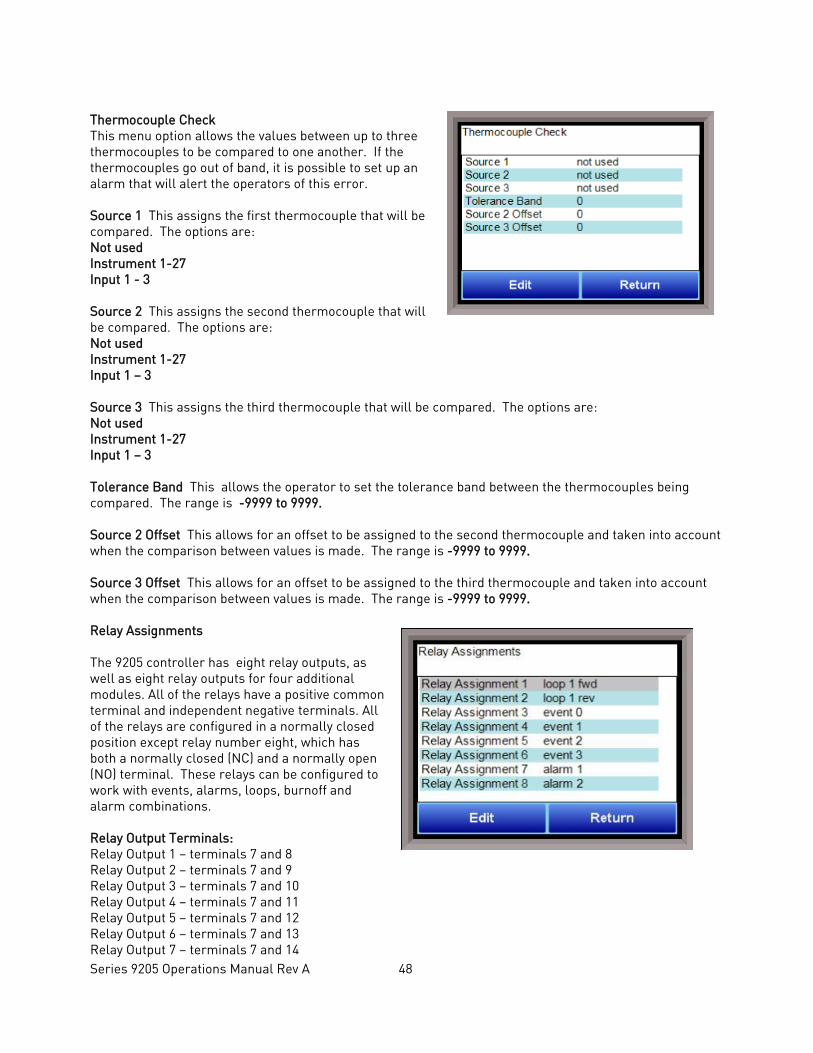
Series 9205 Operations Manual Rev A 48
Thermocouple Check This menu option allows the values between up to three thermocouples to be compared to one another. If the thermocouples go out of band, it is possible to set up an alarm that will alert the operators of this error. Source 1 This assigns the first thermocouple that will be compared. The options are: Not used Instrument 1-27 Input 1 - 3 Source 2 This assigns the second thermocouple that will be compared. The options are: Not used Instrument 1-27 Input 1 – 3 Source 3 This assigns the third thermocouple that will be compared. The options are: Not used Instrument 1-27 Input 1 – 3 Tolerance Band This allows the operator to set the tolerance band between the thermocouples being compared. The range is -9999 to 9999. Source 2 Offset This allows for an offset to be assigned to the second thermocouple and taken into account when the comparison between values is made. The range is -9999 to 9999. Source 3 Offset This allows for an offset to be assigned to the third thermocouple and taken into account when the comparison between values is made. The range is -9999 to 9999. Relay Assignments The 9205 controller has eight relay outputs, as well as eight relay outputs for four additional modules. All of the relays have a positive common terminal and independent negative terminals. All of the relays are configured in a normally closed position except relay number eight, which has both a normally closed (NC) and a normally open (NO) terminal. These relays can be configured to work with events, alarms, loops, burnoff and alarm combinations. Relay Output Terminals: Relay Output 1 – terminals 7 and 8 Relay Output 2 – terminals 7 and 9 Relay Output 3 – terminals 7 and 10 Relay Output 4 – terminals 7 and 11 Relay Output 5 – terminals 7 and 12 Relay Output 6 – terminals 7 and 13 Relay Output 7 – terminals 7 and 14
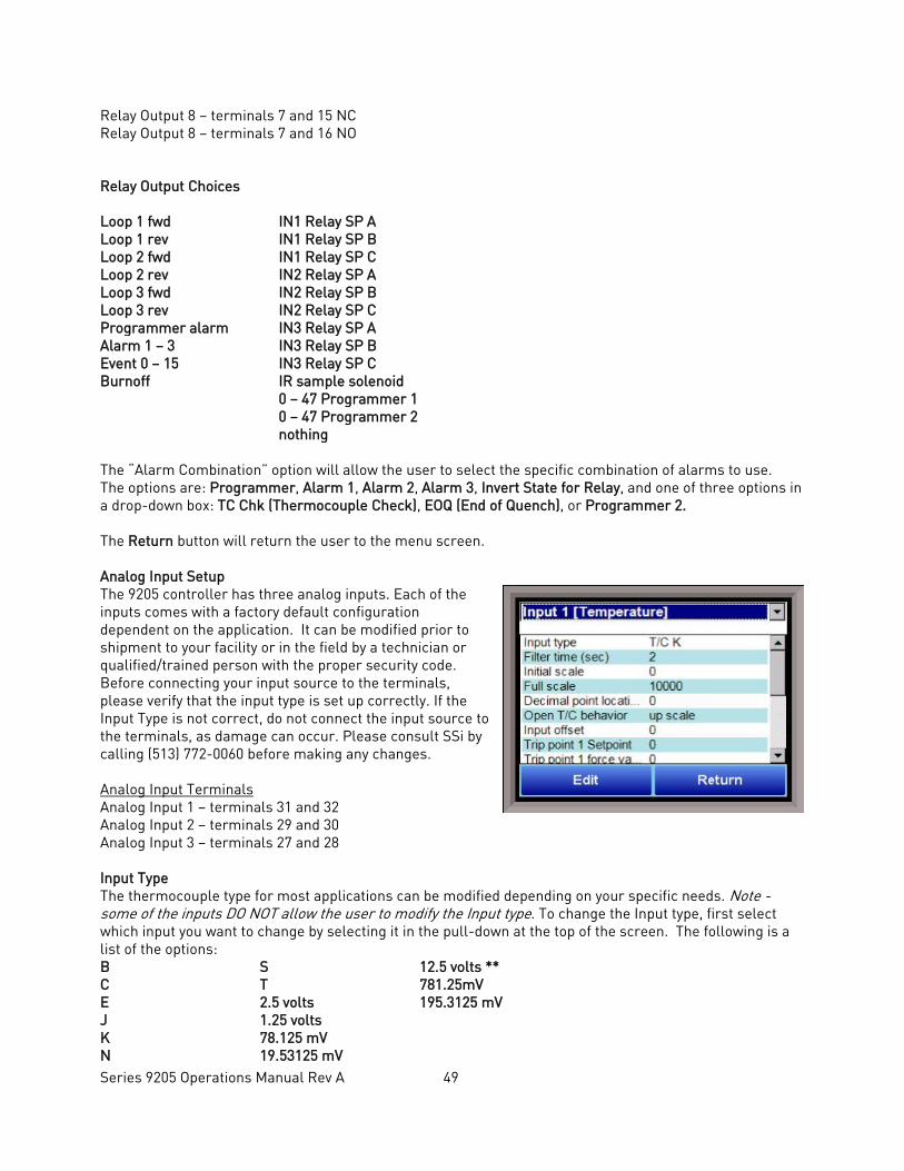
Series 9205 Operations Manual Rev A 49
Relay Output 8 – terminals 7 and 15 NC Relay Output 8 – terminals 7 and 16 NO
Relay Output Choices
Loop 1 fwd IN1 Relay SP A Loop 1 rev IN1 Relay SP B Loop 2 fwd IN1 Relay SP C Loop 2 rev IN2 Relay SP A Loop 3 fwd IN2 Relay SP B Loop 3 rev IN2 Relay SP C Programmer alarm IN3 Relay SP A Alarm 1 – 3 IN3 Relay SP B Event 0 – 15 IN3 Relay SP C Burnoff IR sample solenoid 0 – 47 Programmer 1 0 – 47 Programmer 2 nothing The “Alarm Combination” option will allow the user to select the specific combination of alarms to use. The options are: Programmer, Alarm 1, Alarm 2, Alarm 3, Invert State for Relay, and one of three options in a drop-down box: TC Chk (Thermocouple Check), EOQ (End of Quench), or Programmer 2. The Return button will return the user to the menu screen. Analog Input Setup The 9205 controller has three analog inputs. Each of the inputs comes with a factory default configuration dependent on the application. It can be modified prior to shipment to your facility or in the field by a technician or qualified/trained person with the proper security code. Before connecting your input source to the terminals, please verify that the input type is set up correctly. If the Input Type is not correct, do not connect the input source to the terminals, as damage can occur. Please consult SSi by calling (513) 772-0060 before making any changes. Analog Input Terminals Analog Input 1 – terminals 31 and 32 Analog Input 2 – terminals 29 and 30 Analog Input 3 – terminals 27 and 28 Input Type The thermocouple type for most applications can be modified depending on your specific needs. Note - some of the inputs DO NOT allow the user to modify the Input type. To change the Input type, first select which input you want to change by selecting it in the pull-down at the top of the screen. The following is a list of the options: B S 12.5 volts ** C T 781.25mV E 2.5 volts 195.3125 mV J 1.25 volts K 78.125 mV N 19.53125 mV

Series 9205 Operations Manual Rev A 50
NNM 4-20 mA ** R 25 volts ** ** - When the specified input type is selected, a jumper located inside the case will need to be placed on that specific input for reading this selection. If jumper is not placed on input, then damage could occur to the board. Please consult SSI before making any changes. Filter time The filter time is a factory applied averaging tool used to help maintain steady control in high EMI environments. The filter time should not be adjusted without consulting SSI. Clicking on this value will display an input box from which the user can select a new value. The range is 0 to 32767. Initial Scale This is the initial scale value. This could also be referred to as the starting value. For example, the initial value is the value when 0 volts is on the selected input; or on a 4-20 mA input, it would be the value at the selected input of 4 mA. Clicking on this value will display an input box from which the user can select a new value. The range is –32768 to 32767. Full scale This is the full scale value. Clicking on this value will display an input box from which the user can select a new value. The range is –32768 to 32767. Decimal Point Location This is the decimal point location value. This will affect the PV value and the location of the decimal when it is displayed. Clicking on this value will display an input box from which the user can select a new value. The range is 0 to 4. Open TC behavior This is the open TC value. The options are: up scale, down scale, one trip point, and two trip points. Input Offset The input offset value is algebraically added to the input value to adjust the input curve on read-out. The range is –32768 to 32767. TRIP POINT EXPLANATION: Setting a trip point will force the value that the controller uses for calculations to a certain value as assigned by the operator. Once the Trip Point Setpoint is reached, the controller will begin reading the value as the Trip Point Force Value, regardless of what the actual value is inside the furnace. The Trip Point Direction allows the operator to choose whether the controller will alter its reading when the trip point is either above or below the setpoint. Trip Point 1 Setpoint This is the trip point 1 setpoint value. The range is –32768 to 32767. Trip Point 1 Force Value This is the trip point 1 force value. The range is –32768 to 32767. Trip Point 1 Direction This is the trip point 1 direction. The options are: input above setpoint or input below setpoint.
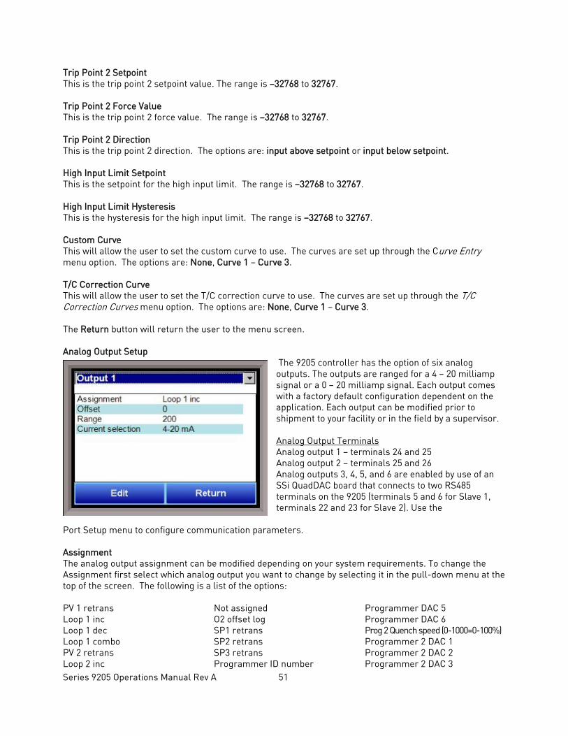
Series 9205 Operations Manual Rev A 51
Trip Point 2 Setpoint This is the trip point 2 setpoint value. The range is –32768 to 32767. Trip Point 2 Force Value This is the trip point 2 force value. The range is –32768 to 32767. Trip Point 2 Direction This is the trip point 2 direction. The options are: input above setpoint or input below setpoint. High Input Limit Setpoint This is the setpoint for the high input limit. The range is –32768 to 32767. High Input Limit Hysteresis This is the hysteresis for the high input limit. The range is –32768 to 32767. Custom Curve This will allow the user to set the custom curve to use. The curves are set up through the Curve Entry menu option. The options are: None, Curve 1 – Curve 3. T/C Correction Curve This will allow the user to set the T/C correction curve to use. The curves are set up through the T/C Correction Curves menu option. The options are: None, Curve 1 – Curve 3. The Return button will return the user to the menu screen. Analog Output Setup
The 9205 controller has the option of six analog outputs. The outputs are ranged for a 4 – 20 milliamp signal or a 0 – 20 milliamp signal. Each output comes with a factory default configuration dependent on the application. Each output can be modified prior to shipment to your facility or in the field by a supervisor. Analog Output Terminals Analog output 1 – terminals 24 and 25 Analog output 2 – terminals 25 and 26 Analog outputs 3, 4, 5, and 6 are enabled by use of an SSi QuadDAC board that connects to two RS485 terminals on the 9205 (terminals 5 and 6 for Slave 1, terminals 22 and 23 for Slave 2). Use the
Port Setup menu to configure communication parameters. Assignment The analog output assignment can be modified depending on your system requirements. To change the Assignment first select which analog output you want to change by selecting it in the pull-down menu at the top of the screen. The following is a list of the options: PV 1 retrans Loop 1 inc Loop 1 dec Loop 1 combo PV 2 retrans Loop 2 inc
Not assigned O2 offset log SP1 retrans SP2 retrans SP3 retrans Programmer ID number
Programmer DAC 5 Programmer DAC 6 Prog 2 Quench speed (0-1000=0-100%) Programmer 2 DAC 1 Programmer 2 DAC 2 Programmer 2 DAC 3
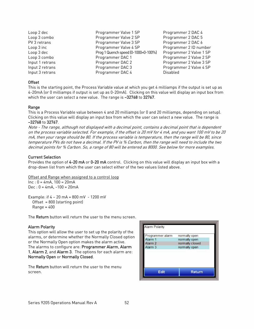
Series 9205 Operations Manual Rev A 52
Loop 2 dec Loop 3 combo PV 3 retrans Loop 3 inc Loop 3 dec Loop 3 combo Input 1 retrans Input 2 retrans Input 3 retrans
Programmer Valve 1 SP Programmer Valve 2 SP Programmer Valve 3 SP Programmer Valve 4 SP Prog 1 Quench speed (0-1000=0-100%) Programmer DAC 1 Programmer DAC 2 Programmer DAC 3 Programmer DAC 4
Programmer 2 DAC 4 Programmer 2 DAC 5 Programmer 2 DAC 6 Programmer 2 ID number Programmer 2 Valve 1 SP Programmer 2 Valve 2 SP Programmer 2 Valve 3 SP Programmer 2 Valve 4 SP Disabled
Offset This is the starting point, the Process Variable value at which you get 4 milliamps if the output is set up as 4-20mA (or 0 milliamps if output is set up as 0-20mA). Clicking on this value will display an input box from which the user can select a new value. The range is –32768 to 32767. Range This is a Process Variable value between 4 and 20 milliamps (or 0 and 20 milliamps, depending on setup). Clicking on this value will display an input box from which the user can select a new value. The range is –32768 to 32767. Note - The range, although not displayed with a decimal point, contains a decimal point that is dependent on the process variable selected. For example, if the offset is 20 mV for 4 mA, and you want 100 mV to be 20 mA, then your range should be 80. If the process variable is temperature, then the range will be 80, since temperature PVs do not have a decimal. If the PV is % Carbon, then the range will need to include the two decimal points for % Carbon. So, a range of 80 will be entered as 8000. See below for more examples. Current Selection Provides the option of 4-20 mA or 0-20 mA control. Clicking on this value will display an input box with a drop-down list from which the user can select either of the two values listed above. Offset and Range when assigned to a control loop Inc : 0 = 4mA, 100 = 20mA Dec : 0 = 4mA, -100 = 20mA Example: if 4 – 20 mA = 800 mV - 1200 mV Offset = 800 (starting point) Range = 400 The Return button will return the user to the menu screen. Alarm Polarity This option will allow the user to set up the polarity of the alarms, or determine whether the Normally Closed option or the Normally Open option makes the alarm active. The alarms to configure are: Programmer Alarm, Alarm 1, Alarm 2, and Alarm 3. The options for each alarm are: Normally Open or Normally Closed. The Return button will return the user to the menu screen.
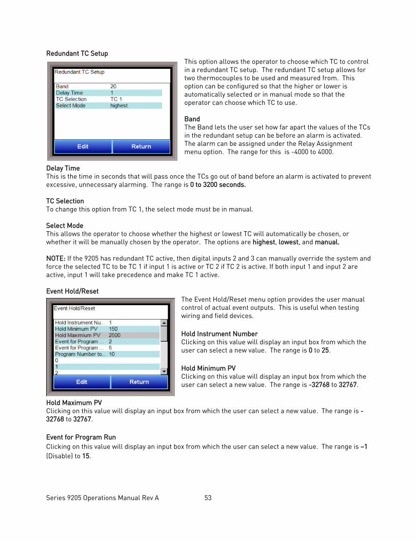
Series 9205 Operations Manual Rev A 53
Redundant TC Setup This option allows the operator to choose which TC to control in a redundant TC setup. The redundant TC setup allows for two thermocouples to be used and measured from. This option can be configured so that the higher or lower is automatically selected or in manual mode so that the operator can choose which TC to use. Band The Band lets the user set how far apart the values of the TCs in the redundant setup can be before an alarm is activated. The alarm can be assigned under the Relay Assignment menu option. The range for this is -4000 to 4000.
Delay Time This is the time in seconds that will pass once the TCs go out of band before an alarm is activated to prevent excessive, unnecessary alarming. The range is 0 to 3200 seconds. TC Selection To change this option from TC 1, the select mode must be in manual. Select Mode This allows the operator to choose whether the highest or lowest TC will automatically be chosen, or whether it will be manually chosen by the operator. The options are highest, lowest, and manual. NOTE: If the 9205 has redundant TC active, then digital inputs 2 and 3 can manually override the system and force the selected TC to be TC 1 if input 1 is active or TC 2 if TC 2 is active. If both input 1 and input 2 are active, input 1 will take precedence and make TC 1 active. Event Hold/Reset
The Event Hold/Reset menu option provides the user manual control of actual event outputs. This is useful when testing wiring and field devices. Hold Instrument Number Clicking on this value will display an input box from which the user can select a new value. The range is 0 to 25. Hold Minimum PV Clicking on this value will display an input box from which the user can select a new value. The range is -32768 to 32767.
Hold Maximum PV Clicking on this value will display an input box from which the user can select a new value. The range is -32768 to 32767. Event for Program Run Clicking on this value will display an input box from which the user can select a new value. The range is –1 (Disable) to 15.

Series 9205 Operations Manual Rev A 54
Event for Program Reset Clicking on this value will display an input box from which the user can select a new value. The range is –1 (Disable) to 15. Program Number to Run This is the recipe number to run. The range is: 0 – 300. Input Event 0 - 15 The input box for these events has two drop-down lists. The top list contains active and inactive, and the bottom list contains closed and open. The Return button will return the user to the menu screen.
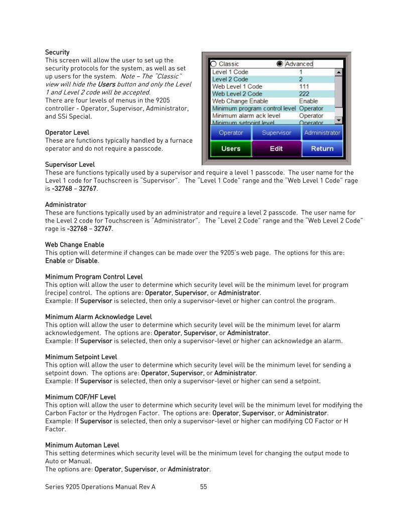
Series 9205 Operations Manual Rev A 55
Security This screen will allow the user to set up the security protocols for the system, as well as set up users for the system. Note – The “Classic” view will hide the Users button and only the Level 1 and Level 2 code will be accepted. There are four levels of menus in the 9205 controller - Operator, Supervisor, Administrator, and SSi Special. Operator Level These are functions typically handled by a furnace operator and do not require a passcode. Supervisor Level These are functions typically used by a supervisor and require a level 1 passcode. The user name for the Level 1 code for Touchscreen is “Supervisor”. The “Level 1 Code” range and the “Web Level 1 Code” rage is -32768 – 32767. Administrator These are functions typically used by an administrator and require a level 2 passcode. The user name for the Level 2 code for Touchscreen is “Administrator”. The “Level 2 Code” range and the “Web Level 2 Code” rage is -32768 – 32767. Web Change Enable This option will determine if changes can be made over the 9205’s web page. The options for this are: Enable or Disable. Minimum Program Control Level This option will allow the user to determine which security level will be the minimum level for program (recipe) control. The options are: Operator, Supervisor, or Administrator. Example: If Supervisor is selected, then only a supervisor-level or higher can control the program. Minimum Alarm Acknowledge Level This option will allow the user to determine which security level will be the minimum level for alarm acknowledgement. The options are: Operator, Supervisor, or Administrator. Example: If Supervisor is selected, then only a supervisor-level or higher can acknowledge an alarm. Minimum Setpoint Level This option will allow the user to determine which security level will be the minimum level for sending a setpoint down. The options are: Operator, Supervisor, or Administrator. Example: If Supervisor is selected, then only a supervisor-level or higher can send a setpoint. Minimum COF/HF Level This option will allow the user to determine which security level will be the minimum level for modifying the Carbon Factor or the Hydrogen Factor. The options are: Operator, Supervisor, or Administrator. Example: If Supervisor is selected, then only a supervisor-level or higher can modifying CO Factor or H Factor. Minimum Automan Level This setting determines which security level will be the minimum level for changing the output mode to Auto or Manual. The options are: Operator, Supervisor, or Administrator.
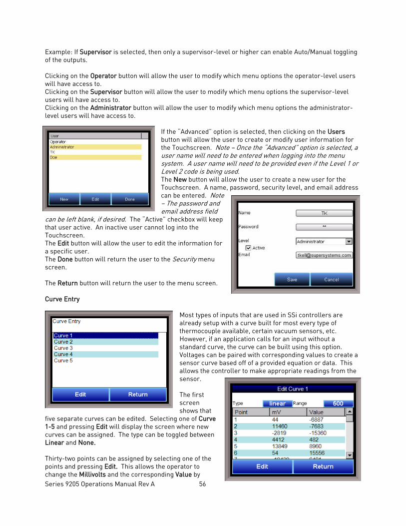
Series 9205 Operations Manual Rev A 56
Example: If Supervisor is selected, then only a supervisor-level or higher can enable Auto/Manual toggling of the outputs. Clicking on the Operator button will allow the user to modify which menu options the operator-level users will have access to. Clicking on the Supervisor button will allow the user to modify which menu options the supervisor-level users will have access to. Clicking on the Administrator button will allow the user to modify which menu options the administrator-level users will have access to.
If the “Advanced” option is selected, then clicking on the Users button will allow the user to create or modify user information for the Touchscreen. Note – Once the “Advanced” option is selected, a user name will need to be entered when logging into the menu system. A user name will need to be provided even if the Level 1 or Level 2 code is being used. The New button will allow the user to create a new user for the Touchscreen. A name, password, security level, and email address can be entered. Note – The password and email address field
can be left blank, if desired. The “Active” checkbox will keep that user active. An inactive user cannot log into the Touchscreen. The Edit button will allow the user to edit the information for a specific user. The Done button will return the user to the Security menu screen. The Return button will return the user to the menu screen. Curve Entry
Most types of inputs that are used in SSi controllers are already setup with a curve built for most every type of thermocouple available, certain vacuum sensors, etc. However, if an application calls for an input without a standard curve, the curve can be built using this option. Voltages can be paired with corresponding values to create a sensor curve based off of a provided equation or data. This allows the controller to make appropriate readings from the sensor. The first screen shows that
five separate curves can be edited. Selecting one of Curve 1-5 and pressing Edit will display the screen where new curves can be assigned. The type can be toggled between Linear and None. Thirty-two points can be assigned by selecting one of the points and pressing Edit. This allows the operator to change the Millivolts and the corresponding Value by
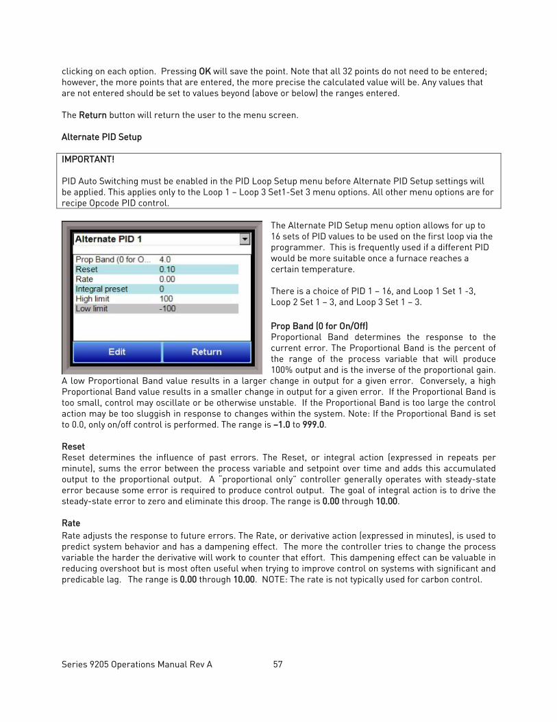
Series 9205 Operations Manual Rev A 57
clicking on each option. Pressing OK will save the point. Note that all 32 points do not need to be entered; however, the more points that are entered, the more precise the calculated value will be. Any values that are not entered should be set to values beyond (above or below) the ranges entered. The Return button will return the user to the menu screen. Alternate PID Setup IMPORTANT! PID Auto Switching must be enabled in the PID Loop Setup menu before Alternate PID Setup settings will be applied. This applies only to the Loop 1 – Loop 3 Set1-Set 3 menu options. All other menu options are for recipe Opcode PID control.
The Alternate PID Setup menu option allows for up to 16 sets of PID values to be used on the first loop via the programmer. This is frequently used if a different PID would be more suitable once a furnace reaches a certain temperature. There is a choice of PID 1 – 16, and Loop 1 Set 1 -3, Loop 2 Set 1 – 3, and Loop 3 Set 1 – 3. Prop Band (0 for On/Off) Proportional Band determines the response to the current error. The Proportional Band is the percent of the range of the process variable that will produce 100% output and is the inverse of the proportional gain.
A low Proportional Band value results in a larger change in output for a given error. Conversely, a high Proportional Band value results in a smaller change in output for a given error. If the Proportional Band is too small, control may oscillate or be otherwise unstable. If the Proportional Band is too large the control action may be too sluggish in response to changes within the system. Note: If the Proportional Band is set to 0.0, only on/off control is performed. The range is –1.0 to 999.0. Reset Reset determines the influence of past errors. The Reset, or integral action (expressed in repeats per minute), sums the error between the process variable and setpoint over time and adds this accumulated output to the proportional output. A “proportional only” controller generally operates with steady-state error because some error is required to produce control output. The goal of integral action is to drive the steady-state error to zero and eliminate this droop. The range is 0.00 through 10.00. Rate Rate adjusts the response to future errors. The Rate, or derivative action (expressed in minutes), is used to predict system behavior and has a dampening effect. The more the controller tries to change the process variable the harder the derivative will work to counter that effort. This dampening effect can be valuable in reducing overshoot but is most often useful when trying to improve control on systems with significant and predicable lag. The range is 0.00 through 10.00. NOTE: The rate is not typically used for carbon control.
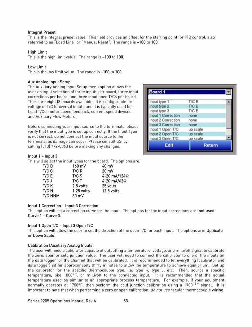
Series 9205 Operations Manual Rev A 58
Integral Preset This is the integral preset value. This field provides an offset for the starting point for PID control, also referred to as “Load Line” or “Manual Reset”. The range is –100 to 100. High Limit This is the high limit value. The range is –100 to 100. Low Limit This is the low limit value. The range is –100 to 100. Aux Analog Input Setup The Auxiliary Analog Input Setup menu option allows the user an input selection of three inputs per board, three input corrections per board, and three input open T/Cs per board. There are eight (8) boards available. It is configurable for voltage of T/C (universal input), and it is typically used for Load T/Cs, motor speed feedback, current speed devices, and Auxiliary Flow Meters. Before connecting your input source to the terminals, please verify that the input type is set up correctly. If the Input Type is not correct, do not connect the input source to the terminals, as damage can occur. Please consult SSi by calling (513) 772-0060 before making any changes. Input 1 – Input 3 This will select the input types for the board. The options are: T/C B 160 mV 40 mV T/C C T/C R 20 mV T/C E T/C S 4-20 mA/124Ω T/C J T/C T 4-20 mA/62Ω T/C K 2.5 volts 25 volts T/C N 1.25 volts 12.5 volts T/C NNM 80 mV Input 1 Correction – Input 3 Correction This option will set a correction curve for the input. The options for the input corrections are: not used, Curve 1 – Curve 3. Input 1 Open T/C – Input 3 Open T/C This option will allow the user to set the direction of the open T/C for each input. The options are: Up Scale or Down Scale. Calibration (Auxiliary Analog Inputs) The user will need a calibrator capable of outputting a temperature, voltage, and millivolt signal to calibrate the zero, span or cold junction value. The user will need to connect the calibrator to one of the inputs on the data logger for the channel that will be calibrated. It is recommended to let everything (calibrator and data logger) sit for approximately thirty minutes to allow the temperature to achieve equilibrium. Set up the calibrator for the specific thermocouple type, i.e. type K, type J, etc. Then, source a specific temperature, like 1000°F, or millivolt to the connected input. It is recommended that the actual temperature used be similar to an appropriate process temperature. For example, if your equipment normally operates at 1700°F, then perform the cold junction calibration using a 1700 °F signal. It is important to note that when performing a zero or span calibration, do not use regular thermocouple wiring.
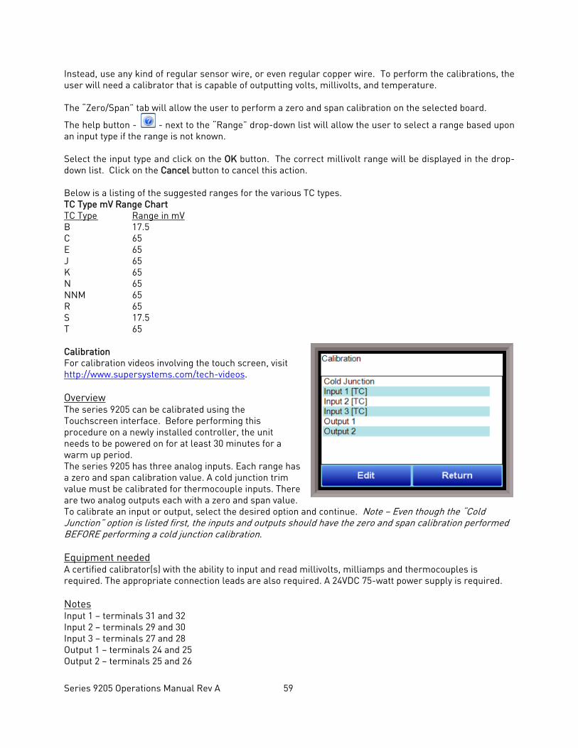
Series 9205 Operations Manual Rev A 59
Instead, use any kind of regular sensor wire, or even regular copper wire. To perform the calibrations, the user will need a calibrator that is capable of outputting volts, millivolts, and temperature. The “Zero/Span” tab will allow the user to perform a zero and span calibration on the selected board.
The help button - - next to the “Range” drop-down list will allow the user to select a range based upon an input type if the range is not known. Select the input type and click on the OK button. The correct millivolt range will be displayed in the drop-down list. Click on the Cancel button to cancel this action. Below is a listing of the suggested ranges for the various TC types. TC Type mV Range Chart TC Type Range in mV B 17.5 C 65 E 65 J 65 K 65 N 65 NNM 65 R 65 S 17.5 T 65 Calibration For calibration videos involving the touch screen, visit http://www.supersystems.com/tech-videos. Overview The series 9205 can be calibrated using the Touchscreen interface. Before performing this procedure on a newly installed controller, the unit needs to be powered on for at least 30 minutes for a warm up period. The series 9205 has three analog inputs. Each range has a zero and span calibration value. A cold junction trim value must be calibrated for thermocouple inputs. There are two analog outputs each with a zero and span value. To calibrate an input or output, select the desired option and continue. Note – Even though the “Cold Junction” option is listed first, the inputs and outputs should have the zero and span calibration performed BEFORE performing a cold junction calibration. Equipment needed A certified calibrator(s) with the ability to input and read millivolts, milliamps and thermocouples is required. The appropriate connection leads are also required. A 24VDC 75-watt power supply is required. Notes Input 1 – terminals 31 and 32 Input 2 – terminals 29 and 30 Input 3 – terminals 27 and 28 Output 1 – terminals 24 and 25 Output 2 – terminals 25 and 26
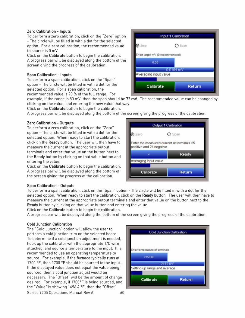
Series 9205 Operations Manual Rev A 60
Zero Calibration - Inputs To perform a zero calibration, click on the “Zero” option - The circle will be filled in with a dot for the selected option. For a zero calibration, the recommended value to source is 0 mV. Click on the Calibrate button to begin the calibration. A progress bar will be displayed along the bottom of the screen giving the progress of the calibration. Span Calibration - Inputs To perform a span calibration, click on the “Span” option - The circle will be filled in with a dot for the selected option. For a span calibration, the recommended value is 90 % of the full range. For example, if the range is 80 mV, then the span should be 72 mV. The recommended value can be changed by clicking on the value, and entering the new value that way. Click on the Calibrate button to begin the calibration. A progress bar will be displayed along the bottom of the screen giving the progress of the calibration. Zero Calibration - Outputs To perform a zero calibration, click on the “Zero” option - The circle will be filled in with a dot for the selected option. When ready to start the calibration, click on the Ready button. The user will then have to measure the current at the appropriate output terminals and enter that value on the button next to the Ready button by clicking on that value button and entering the value. Click on the Calibrate button to begin the calibration. A progress bar will be displayed along the bottom of the screen giving the progress of the calibration. Span Calibration - Outputs To perform a span calibration, click on the “Span” option - The circle will be filled in with a dot for the selected option. When ready to start the calibration, click on the Ready button. The user will then have to measure the current at the appropriate output terminals and enter that value on the button next to the Ready button by clicking on that value button and entering the value. Click on the Calibrate button to begin the calibration. A progress bar will be displayed along the bottom of the screen giving the progress of the calibration. Cold Junction Calibration The “Cold Junction” option will allow the user to perform a cold junction trim on the selected board. To determine if a cold junction adjustment is needed, hook up the calibrator with the appropriate T/C wire attached, and source a temperature to the input. It is recommended to use an operating temperature to source. For example, if the furnace typically runs at 1700 °F, then 1700 °F should be sourced to the input. If the displayed value does not equal the value being sourced, then a cold junction adjust would be necessary. The “Offset” will be the amount of change desired. For example, if 1700°F is being sourced, and the “Value” is showing 1696.4 °F, then the “Offset”
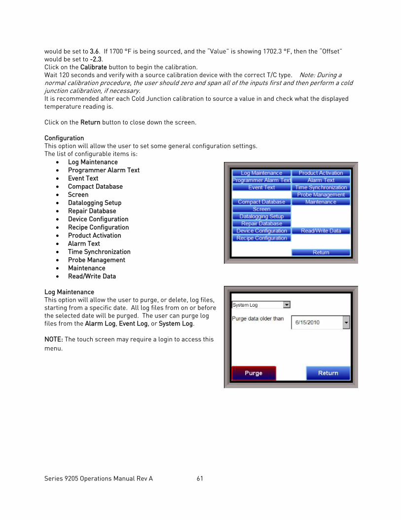
Series 9205 Operations Manual Rev A 61
would be set to 3.6. If 1700 °F is being sourced, and the “Value” is showing 1702.3 °F, then the “Offset” would be set to -2.3. Click on the Calibrate button to begin the calibration. Wait 120 seconds and verify with a source calibration device with the correct T/C type. Note: During a normal calibration procedure, the user should zero and span all of the inputs first and then perform a cold junction calibration, if necessary. It is recommended after each Cold Junction calibration to source a value in and check what the displayed temperature reading is. Click on the Return button to close down the screen. Configuration This option will allow the user to set some general configuration settings. The list of configurable items is:
• Log Maintenance • Programmer Alarm Text • Event Text • Compact Database • Screen • Datalogging Setup • Repair Database • Device Configuration • Recipe Configuration • Product Activation • Alarm Text • Time Synchronization • Probe Management • Maintenance • Read/Write Data
Log Maintenance This option will allow the user to purge, or delete, log files, starting from a specific date. All log files from on or before the selected date will be purged. The user can purge log files from the Alarm Log, Event Log, or System Log. NOTE: The touch screen may require a login to access this menu.
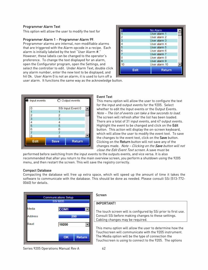
Series 9205 Operations Manual Rev A 62
Programmer Alarm Text This option will allow the user to modify the text for Programmer Alarm 1 – Programmer Alarm 99. Programmer alarms are internal, non-modifiable alarms that are triggered with the Alarm opcode in a recipe. Each alarm is initially labeled by the text “User Alarm #.” However, these labels can be changed to the operator’s preference. To change the text displayed for an alarm, open the Configurator program, open the Settings, and select the controller to edit. Under Alarm Text, double click any alarm number, enter the new text to be displayed, and hit Ok. User Alarm 0 is not an alarm; it is used to turn off a user alarm. It functions the same way as the acknowledge button.
Event Text This menu option will allow the user to configure the text for the input and output events for the 9205. Select whether to edit the Input events or the Output Events. Note – The list of events can take a few seconds to load. The screen will refresh after the list has been loaded. There are a total of 31 input events, and 47 output events. Highlight the event to be changed and click on the Edit button. This action will display the on-screen keyboard, which will allow the user to modify the event text. To save the changes to the event text, click on the Save button. Clicking on the Return button will not save any of the changes made. Note – Clicking on the Save button will not close the Edit Event Text screen. A save must be
performed before switching from the input events to the outputs events, and vice versa. It is also recommended that after you return to the main overview screen, you perform a shutdown using the 9205 menu, and then restart the screen. This will save the registry correctly. Compact Database Compacting the database will free up extra space, which will speed up the amount of time it takes the software to communicate with the database. This should be done as needed. Please consult SSi (513-772-0060) for details.
Screen IMPORTANT! The touch screen will is configured by SSi prior to first use. Consult SSi before making changes to these settings. Cabling changes may be required. This menu option will allow the user to determine how the Touchscreen will communicate with the 9205 instrument. The Media option will be the type of connection the Touchscreen is using to connect to the 9205. The options
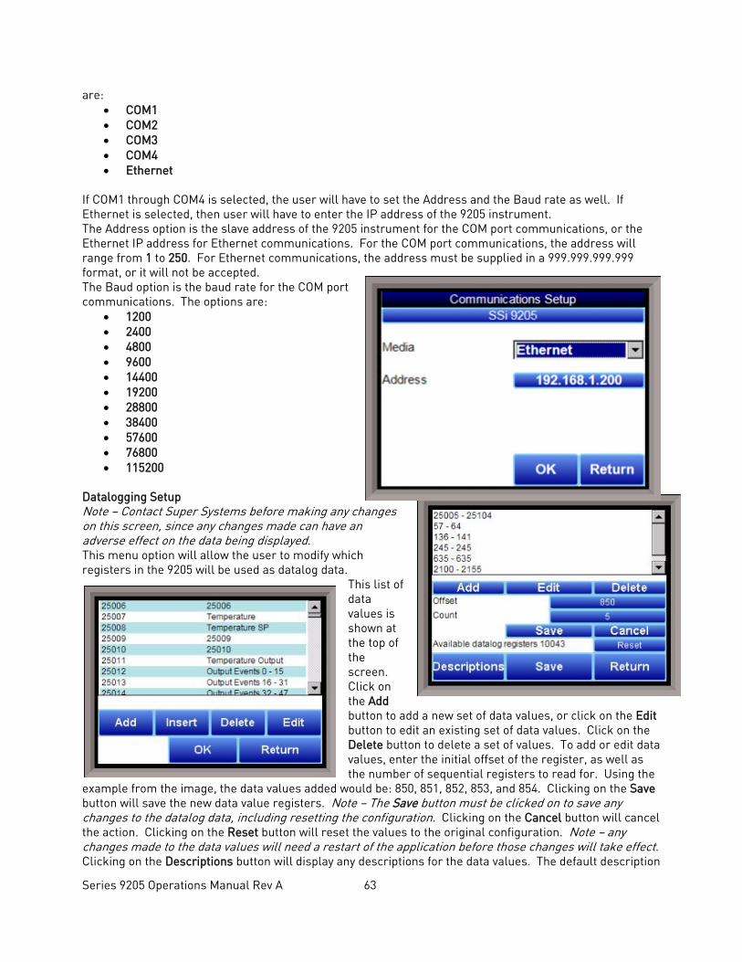
Series 9205 Operations Manual Rev A 63
are: • COM1 • COM2 • COM3 • COM4 • Ethernet
If COM1 through COM4 is selected, the user will have to set the Address and the Baud rate as well. If Ethernet is selected, then user will have to enter the IP address of the 9205 instrument. The Address option is the slave address of the 9205 instrument for the COM port communications, or the Ethernet IP address for Ethernet communications. For the COM port communications, the address will range from 1 to 250. For Ethernet communications, the address must be supplied in a 999.999.999.999 format, or it will not be accepted. The Baud option is the baud rate for the COM port communications. The options are:
• 1200 • 2400 • 4800 • 9600 • 14400 • 19200 • 28800 • 38400 • 57600 • 76800 • 115200
Datalogging Setup Note – Contact Super Systems before making any changes on this screen, since any changes made can have an adverse effect on the data being displayed. This menu option will allow the user to modify which registers in the 9205 will be used as datalog data.
This list of data values is shown at the top of the screen. Click on the Add button to add a new set of data values, or click on the Edit button to edit an existing set of data values. Click on the Delete button to delete a set of values. To add or edit data values, enter the initial offset of the register, as well as the number of sequential registers to read for. Using the
example from the image, the data values added would be: 850, 851, 852, 853, and 854. Clicking on the Save button will save the new data value registers. Note – The Save button must be clicked on to save any changes to the datalog data, including resetting the configuration. Clicking on the Cancel button will cancel the action. Clicking on the Reset button will reset the values to the original configuration. Note – any changes made to the data values will need a restart of the application before those changes will take effect. Clicking on the Descriptions button will display any descriptions for the data values. The default description
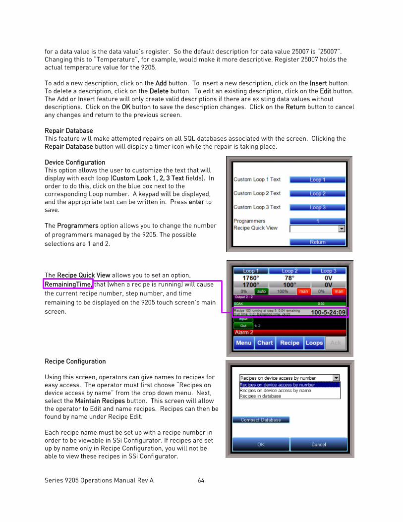
Series 9205 Operations Manual Rev A 64
for a data value is the data value’s register. So the default description for data value 25007 is “25007”. Changing this to “Temperature”, for example, would make it more descriptive. Register 25007 holds the actual temperature value for the 9205. To add a new description, click on the Add button. To insert a new description, click on the Insert button. To delete a description, click on the Delete button. To edit an existing description, click on the Edit button. The Add or Insert feature will only create valid descriptions if there are existing data values without descriptions. Click on the OK button to save the description changes. Click on the Return button to cancel any changes and return to the previous screen. Repair Database This feature will make attempted repairs on all SQL databases associated with the screen. Clicking the Repair Database button will display a timer icon while the repair is taking place. Device Configuration This option allows the user to customize the text that will display with each loop (Custom Look 1, 2, 3 Text fields). In order to do this, click on the blue box next to the corresponding Loop number. A keypad will be displayed, and the appropriate text can be written in. Press enter to save. The Programmers option allows you to change the number of programmers managed by the 9205. The possible selections are 1 and 2.
The Recipe Quick View allows you to set an option, RemainingTime, that (when a recipe is running) will cause the current recipe number, step number, and time remaining to be displayed on the 9205 touch screen’s main screen.
Recipe Configuration
Using this screen, operators can give names to recipes for easy access. The operator must first choose “Recipes on device access by name” from the drop down menu. Next, select the Maintain Recipes button. This screen will allow the operator to Edit and name recipes. Recipes can then be found by name under Recipe Edit. Each recipe name must be set up with a recipe number in order to be viewable in SSi Configurator. If recipes are set up by name only in Recipe Configuration, you will not be able to view these recipes in SSi Configurator.
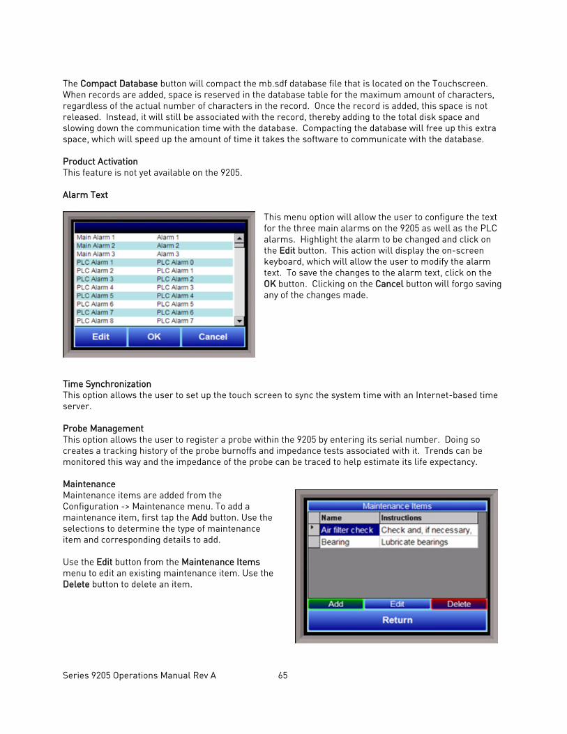
Series 9205 Operations Manual Rev A 65
The Compact Database button will compact the mb.sdf database file that is located on the Touchscreen. When records are added, space is reserved in the database table for the maximum amount of characters, regardless of the actual number of characters in the record. Once the record is added, this space is not released. Instead, it will still be associated with the record, thereby adding to the total disk space and slowing down the communication time with the database. Compacting the database will free up this extra space, which will speed up the amount of time it takes the software to communicate with the database. Product Activation This feature is not yet available on the 9205. Alarm Text
This menu option will allow the user to configure the text for the three main alarms on the 9205 as well as the PLC alarms. Highlight the alarm to be changed and click on the Edit button. This action will display the on-screen keyboard, which will allow the user to modify the alarm text. To save the changes to the alarm text, click on the OK button. Clicking on the Cancel button will forgo saving any of the changes made.
Time Synchronization This option allows the user to set up the touch screen to sync the system time with an Internet-based time server. Probe Management This option allows the user to register a probe within the 9205 by entering its serial number. Doing so creates a tracking history of the probe burnoffs and impedance tests associated with it. Trends can be monitored this way and the impedance of the probe can be traced to help estimate its life expectancy. Maintenance Maintenance items are added from the Configuration -> Maintenance menu. To add a maintenance item, first tap the Add button. Use the selections to determine the type of maintenance item and corresponding details to add. Use the Edit button from the Maintenance Items menu to edit an existing maintenance item. Use the Delete button to delete an item.
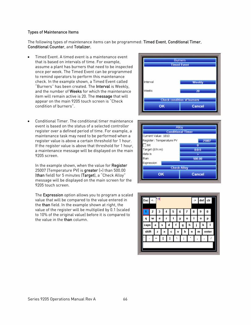
Series 9205 Operations Manual Rev A 66
Types of Maintenance Items The following types of maintenance items can be programmed: Timed Event, Conditional Timer, Conditional Counter, and Totalizer. • Timed Event. A timed event is a maintenance event
that is based on intervals of time. For example, assume a plant has burners that need to be inspected once per week. The Timed Event can be programmed to remind operators to perform this maintenance check. In the example shown, a Timed Event called “Burners” has been created. The Interval is Weekly, and the number of Weeks for which the maintenance item will remain active is 20. The message that will appear on the main 9205 touch screen is “Check condition of burners”.
• Conditional Timer. The conditional timer maintenance event is based on the status of a selected controller register over a defined period of time. For example, a maintenance task may need to be performed when a register value is above a certain threshold for 1 hour. If the register value is above that threshold for 1 hour, a maintenance message will be displayed on the main 9205 screen.
In the example shown, when the value for Register 25007 (Temperature PV) is greater (>) than 500.00 (than field) for 5 minutes (Target), a “Check Alloy” message will be displayed on the main screen for the 9205 touch screen. The Expression option allows you to program a scaled value that will be compared to the value entered in the than field. In the example shown at right, the value of the register will be multiplied by 0.1 (scaled to 10% of the original value) before it is compared to the value in the than column.
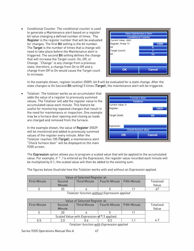
Series 9205 Operations Manual Rev A 67
• Conditional Counter. The conditional counter is used
to generate a Maintenance alert based on a register bit value changing a defined number of times. The Register is the register number that will be evaluated for changes. The first Bit setting is the bit number. The Target is the number of times that a change will need to take place before the Maintenance alert is triggered. The second Bit setting defines the change that will increase the Target count: On, Off, or Change. “Change” is any change from a previous state; therefore, a change from On to Off and a change from Off to On would cause the Target count to increase.
In the example shown, register location 25009, bit 8 will be evaluated for a state change. After the state changes to On (second Bit setting) 5 times (Target), the maintenance alert will be triggered.
• Totalizer. The totalizer works as an accumulator that
adds the value of a register to previously summed values. The Totalizer will add the register value to the accumulated value each minute. This feature be useful for monitoring repeated changes that result in the need for maintenance or inspection. One example may be a furnace door opening and closing as loads are charged and removed from the furnace.
In the example shown, the value of Register 25029 will be monitored and added to previously summed values of the register every minute. After the Totalizer reaches 100 (Target), a maintenance alert “Check furnace door” will be displayed on the main 9205 screen. The Expression option allows you to program a scaled value that will be applied to the accumulated value. For example, if * .1 is entered as the Expression, the register value recorded each minute will be multiplied by 0.1; the scaled value will then be added to the existing sum. The figures below illustrate how the Totalizer works with and without an Expression applied.
Value of Selected Register at: First Minute Second
Minute Third Minute Fourth Minute Fifth Minute Totalized
Value 5 20 6 5 11 47
Totalizer function without Expression applied
Value of Selected Register at: First Minute Second
Minute Third Minute Fourth Minute Fifth Minute Totalized
Value 5 20 6 5 11
4.7
Scaled Value with Expression of *.1 applied: 0.5 2.0 0.6 0.5 1.1
Totalizer function with Expression applied
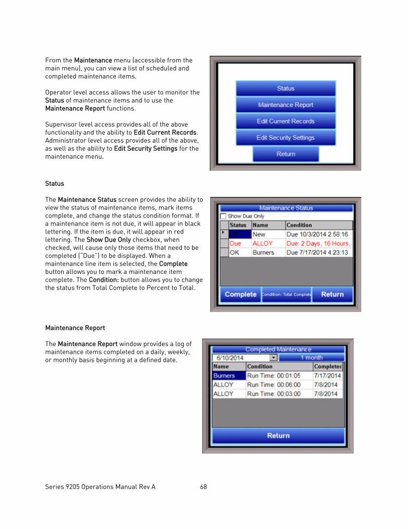
Series 9205 Operations Manual Rev A 68
From the Maintenance menu (accessible from the main menu), you can view a list of scheduled and completed maintenance items. Operator level access allows the user to monitor the Status of maintenance items and to use the Maintenance Report functions. Supervisor level access provides all of the above functionality and the ability to Edit Current Records. Administrator level access provides all of the above, as well as the ability to Edit Security Settings for the maintenance menu.
Status The Maintenance Status screen provides the ability to view the status of maintenance items, mark items complete, and change the status condition format. If a maintenance item is not due, it will appear in black lettering. If the item is due, it will appear in red lettering. The Show Due Only checkbox, when checked, will cause only those items that need to be completed (“Due”) to be displayed. When a maintenance line item is selected, the Complete button allows you to mark a maintenance item complete. The Condition: button allows you to change the status from Total Complete to Percent to Total. Maintenance Report The Maintenance Report window provides a log of maintenance items completed on a daily, weekly, or monthly basis beginning at a defined date.
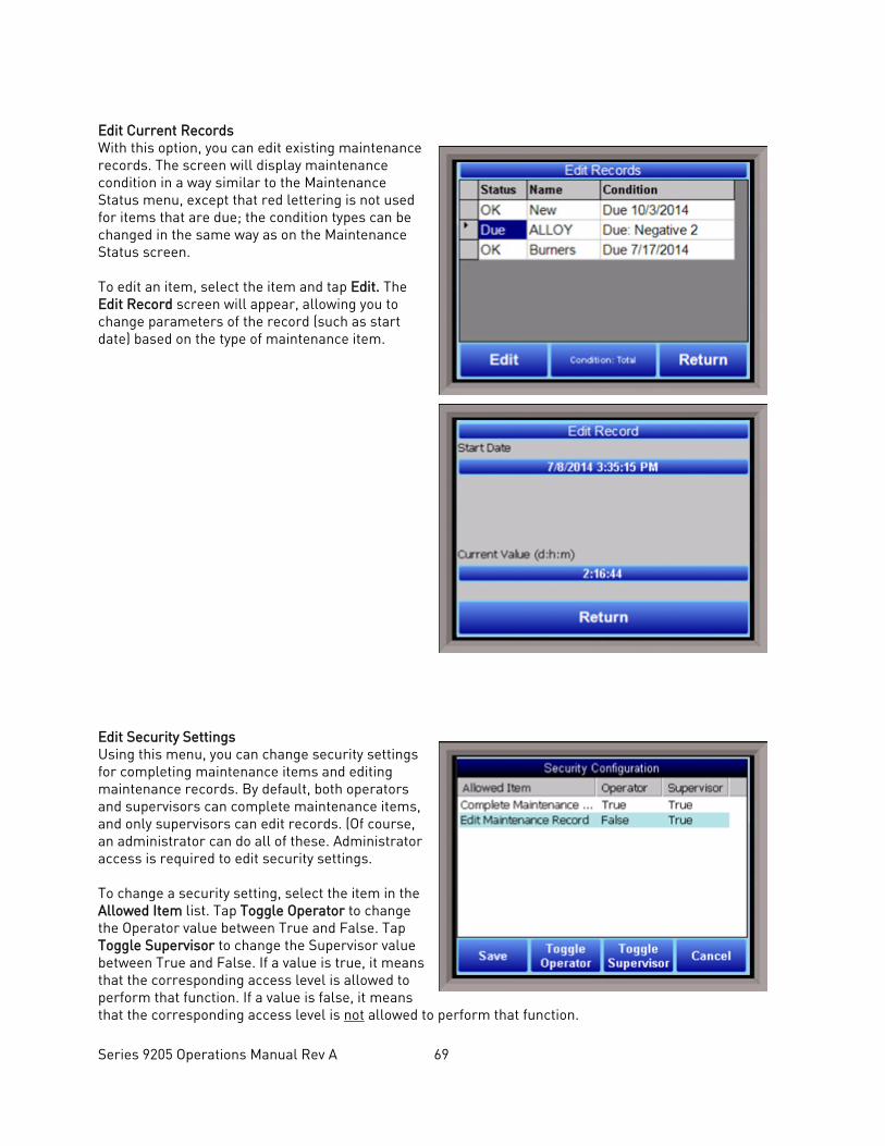
Series 9205 Operations Manual Rev A 69
Edit Current Records With this option, you can edit existing maintenance records. The screen will display maintenance condition in a way similar to the Maintenance Status menu, except that red lettering is not used for items that are due; the condition types can be changed in the same way as on the Maintenance Status screen. To edit an item, select the item and tap Edit. The Edit Record screen will appear, allowing you to change parameters of the record (such as start date) based on the type of maintenance item.
Edit Security Settings Using this menu, you can change security settings for completing maintenance items and editing maintenance records. By default, both operators and supervisors can complete maintenance items, and only supervisors can edit records. (Of course, an administrator can do all of these. Administrator access is required to edit security settings. To change a security setting, select the item in the Allowed Item list. Tap Toggle Operator to change the Operator value between True and False. Tap Toggle Supervisor to change the Supervisor value between True and False. If a value is true, it means that the corresponding access level is allowed to perform that function. If a value is false, it means that the corresponding access level is not allowed to perform that function.
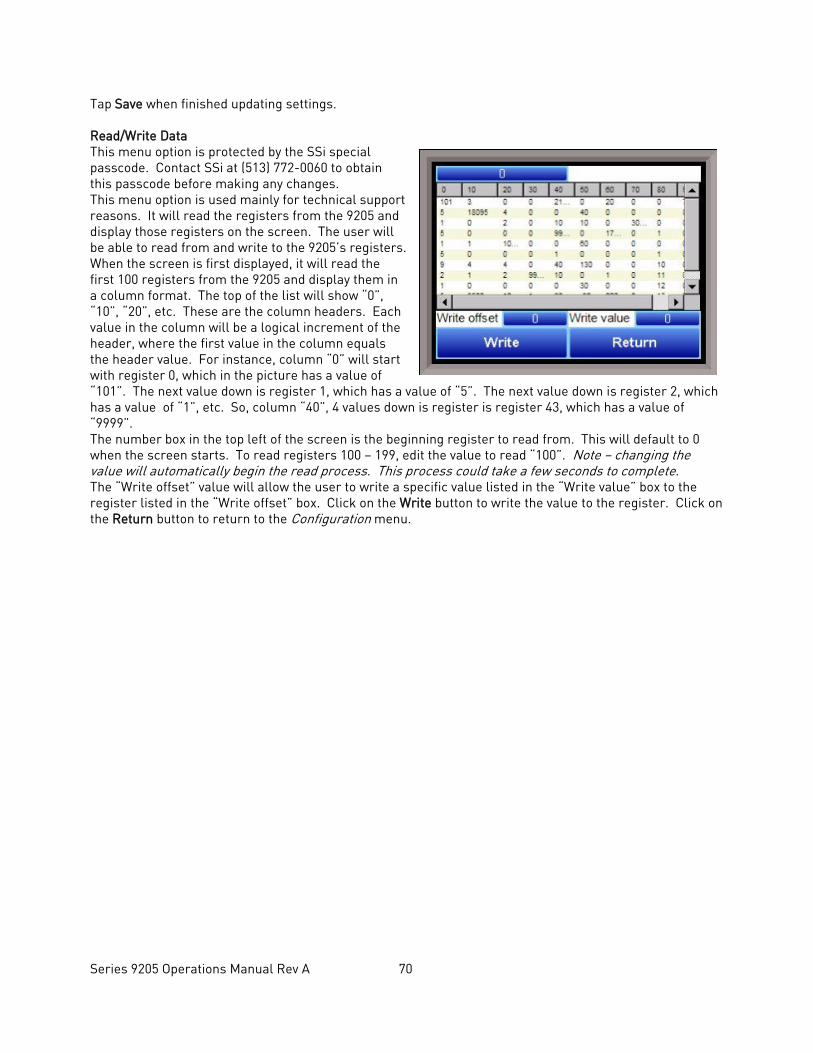
Series 9205 Operations Manual Rev A 70
Tap Save when finished updating settings. Read/Write Data This menu option is protected by the SSi special passcode. Contact SSi at (513) 772-0060 to obtain this passcode before making any changes. This menu option is used mainly for technical support reasons. It will read the registers from the 9205 and display those registers on the screen. The user will be able to read from and write to the 9205’s registers. When the screen is first displayed, it will read the first 100 registers from the 9205 and display them in a column format. The top of the list will show “0”, “10”, “20”, etc. These are the column headers. Each value in the column will be a logical increment of the header, where the first value in the column equals the header value. For instance, column “0” will start with register 0, which in the picture has a value of “101”. The next value down is register 1, which has a value of “5”. The next value down is register 2, which has a value of “1”, etc. So, column “40”, 4 values down is register is register 43, which has a value of “9999”. The number box in the top left of the screen is the beginning register to read from. This will default to 0 when the screen starts. To read registers 100 – 199, edit the value to read “100”. Note – changing the value will automatically begin the read process. This process could take a few seconds to complete. The “Write offset” value will allow the user to write a specific value listed in the “Write value” box to the register listed in the “Write offset” box. Click on the Write button to write the value to the register. Click on the Return button to return to the Configuration menu.
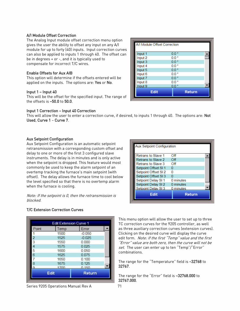
Series 9205 Operations Manual Rev A 71
A/I Module Offset Correction The Analog Input module offset correction menu option gives the user the ability to offset any input on any A/I module for up to forty (40) inputs. Input correction curves can also be applied to inputs 1 through 40. The offset can be in degrees + or -, and it is typically used to compensate for incorrect T/C wires. Enable Offsets for Aux AIB This option will determine if the offsets entered will be applied on the inputs. The options are: Yes or No. Input 1 – Input 40 This will be the offset for the specified input. The range of the offsets is –50.0 to 50.0. Input 1 Correction – Input 40 Correction This will allow the user to enter a correction curve, if desired, to inputs 1 through 40. The options are: Not Used, Curve 1 – Curve 7.
Aux Setpoint Configuration Aux Setpoint Configuration is an automatic setpoint retransmission with a corresponding custom offset and delay to one or more of the first 3 configured slave instruments. The delay is in minutes and is only active when the setpoint is dropped. This feature would most commonly be used to keep the alarm setpoint of an overtemp tracking the furnace's main setpoint (with offset). The delay allows the furnace time to cool below the level specified so that there is no overtemp alarm when the furnace is cooling. Note: If the setpoint is 0, then the retransmission is blocked. T/C Extension Correction Curves
This menu option will allow the user to set up to three TC correction curves for the 9205 controller, as well as three auxiliary correction curves (extension curves). Clicking on the desired curve will display the curve edit form. Note: If the first “Temp” value and the first “Error” value are both zero, then the curve will not be set. The user can enter up to ten “Temp”/“Error” combinations. The range for the “Temperature” field is –32768 to 32767. The range for the “Error” field is –32768.000 to 32767.000.
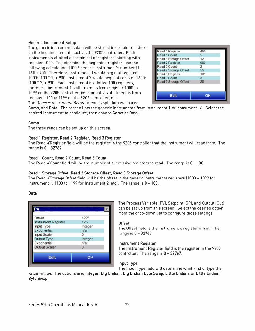
Series 9205 Operations Manual Rev A 72
Generic Instrument Setup The generic instrument’s data will be stored in certain registers on the host instrument, such as the 9205 controller. Each instrument is allotted a certain set of registers, starting with register 1000. To determine the beginning register, use the following calculation: (100 * generic instrument’s number (1 – 16)) + 900. Therefore, instrument 1 would begin at register 1000: (100 * 1) + 900. Instrument 7 would begin at register 1600: (100 * 7) + 900. Each instrument is allotted 100 registers, therefore, instrument 1’s allotment is from register 1000 to 1099 on the 9205 controller, instrument 2’s allotment is from register 1100 to 1199 on the 9205 controller, etc. The Generic Instrument Setups menu is split into two parts: Coms, and Data. The screen lists the generic instruments from Instrument 1 to Instrument 16. Select the desired instrument to configure, then choose Coms or Data. Coms The three reads can be set up on this screen. Read 1 Register, Read 2 Register, Read 3 Register The Read X Register field will be the register in the 9205 controller that the instrument will read from. The range is 0 – 32767. Read 1 Count, Read 2 Count, Read 3 Count The Read X Count field will be the number of successive registers to read. The range is 0 – 100. Read 1 Storage Offset, Read 2 Storage Offset, Read 3 Storage Offset The Read X Storage Offset field will be the offset in the generic instruments registers (1000 – 1099 for Instrument 1, 1100 to 1199 for Instrument 2, etc). The range is 0 – 100. Data
The Process Variable (PV), Setpoint (SP), and Output (Out) can be set up from this screen. Select the desired option from the drop-down list to configure those settings. Offset The Offset field is the instrument’s register offset. The range is 0 – 32767. Instrument Register The Instrument Register field is the register in the 9205 controller. The range is 0 – 32767. Input Type The Input Type field will determine what kind of type the
value will be. The options are: Integer, Big Endian, Big Endian Byte Swap, Little Endian, or Little Endian Byte Swap.
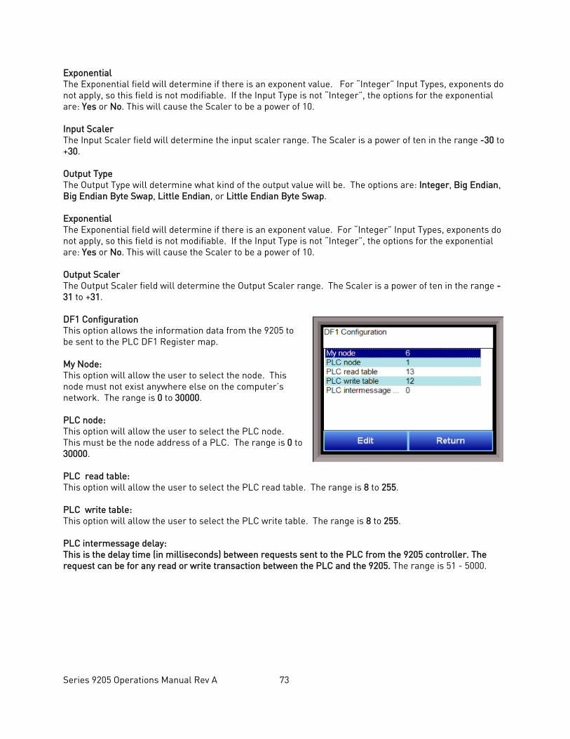
Series 9205 Operations Manual Rev A 73
Exponential The Exponential field will determine if there is an exponent value. For “Integer” Input Types, exponents do not apply, so this field is not modifiable. If the Input Type is not “Integer”, the options for the exponential are: Yes or No. This will cause the Scaler to be a power of 10. Input Scaler The Input Scaler field will determine the input scaler range. The Scaler is a power of ten in the range -30 to +30. Output Type The Output Type will determine what kind of the output value will be. The options are: Integer, Big Endian, Big Endian Byte Swap, Little Endian, or Little Endian Byte Swap. Exponential The Exponential field will determine if there is an exponent value. For “Integer” Input Types, exponents do not apply, so this field is not modifiable. If the Input Type is not “Integer”, the options for the exponential are: Yes or No. This will cause the Scaler to be a power of 10. Output Scaler The Output Scaler field will determine the Output Scaler range. The Scaler is a power of ten in the range -31 to +31. DF1 Configuration This option allows the information data from the 9205 to be sent to the PLC DF1 Register map. My Node: This option will allow the user to select the node. This node must not exist anywhere else on the computer’s network. The range is 0 to 30000. PLC node: This option will allow the user to select the PLC node. This must be the node address of a PLC. The range is 0 to 30000. PLC read table: This option will allow the user to select the PLC read table. The range is 8 to 255. PLC write table: This option will allow the user to select the PLC write table. The range is 8 to 255. PLC intermessage delay: This is the delay time (in milliseconds) between requests sent to the PLC from the 9205 controller. The request can be for any read or write transaction between the PLC and the 9205. The range is 51 - 5000.
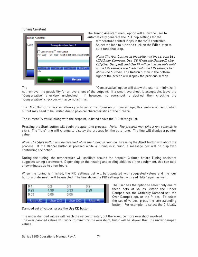
Series 9205 Operations Manual Rev A 74
Tuning Assistant
The Tuning Assistant menu option will allow the user to automatically generate the PID loop settings for the
temperature control loops in the 9205 controller. Select the loop to tune and click on the Edit button to auto tune that loop. Note: The four buttons at the bottom of the screen: Use UD (Under Damped), Use CD (Critically Damped), Use OD (Over Damped), and Use PI will be inaccessible until some PID settings are loaded into the PID settings list above the buttons. The Return button in the bottom right of the screen will display the previous screen.
The “Conservative” option will allow the user to minimize, if not remove, the possibility for an overshoot of the setpoint. If a small overshoot is acceptable, leave the “Conservative” checkbox unchecked. If, however, no overshoot is desired, then checking the “Conservative” checkbox will accomplish this. The “Max Output” checkbox allows you to set a maximum output percentage; this feature is useful when output may need to be limited due to physical characteristics of the furnace. The current PV value, along with the setpoint, is listed above the PID settings list. Pressing the Start button will begin the auto tune process. Note: The process may take a few seconds to start. The “Idle” line will change to display the process for the auto tune. The line will display a pointer value. Note: The Start button will be disabled while the tuning is running. Pressing the Abort button will abort the process. If the Cancel button is pressed while a tuning is running, a message box will be displayed confirming the action. During the tuning, the temperature will oscillate around the setpoint 3 times before Tuning Assistant suggests tuning parameters. Depending on the heating and cooling abilities of the equipment, this can take a few minutes up to a few hours. When the tuning is finished, the PID settings list will be populated with suggested values and the four buttons underneath will be enabled. The line above the PID settings list will read “Idle” again as well.
The user has the option to select only one of these sets of values: either the Under Damped set, the Critically Damped set, the Over Damped set, or the PI set. To select the set of values, press the corresponding button. For example, to select the Critically
Damped set of values, press the Use CD button. The under damped values will reach the setpoint faster, but there will be more overshoot involved. The over damped values will work to minimize the overshoot, but it will be slower than the under damped values.
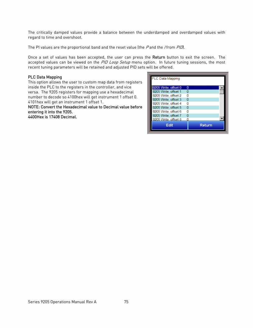
Series 9205 Operations Manual Rev A 75
The critically damped values provide a balance between the underdamped and overdamped values with regard to time and overshoot. The PI values are the proportional band and the reset value (the P and the I from PID). Once a set of values has been accepted, the user can press the Return button to exit the screen. The accepted values can be viewed on the PID Loop Setup menu option. In future tuning sessions, the most recent tuning parameters will be retained and adjusted PID sets will be offered. PLC Data Mapping This option allows the user to custom map data from registers inside the PLC to the registers in the controller, and vice versa. The 9205 registers for mapping use a hexadecimal number to decode so 4100hex will get instrument 1 offset 0. 4101hex will get an instrument 1 offset 1. NOTE: Convert the Hexadecimal value to Decimal value before entering it into the 9205. 4400Hex is 17408 Decimal.
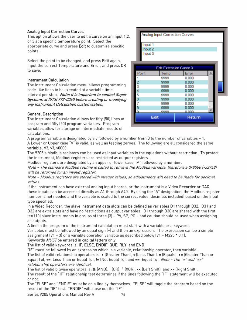
Series 9205 Operations Manual Rev A 76
Analog Input Correction Curves This option allows the user to edit a curve on an input 1,2, or 3 at a specific temperature point. Select the appropriate curve and press Edit to customize specific points. Select the point to be changed, and press Edit again. Input the correct Temperature and Error, and press OK to save. Instrument Calculation The Instrument Calculation menu allows programming code-like lines to be executed at a variable time interval per step. Note: It is important to contact Super Systems at (513) 772-0060 before creating or modifying any Instrument Calculation customization. General Description The Instrument Calculation allows for fifty (50) lines of program and fifty (50) program variables. Program variables allow for storage on intermediate results of calculations. A program variable is designated by a v followed by a number from 0 to the number of variables – 1. A Lower or Upper case “V” is valid, as well as leading zeroes. The following are all considered the same variable: V3, v3, v0003. The 9205’s Modbus registers can be used as input variables in the equations without restriction. To protect the instrument, Modbus registers are restricted as output registers. Modbus registers are designated by an upper or lower case “M” followed by a number. Note – The standard Modbus routine is called to retrieve the Modbus variable, therefore a 0x8000 (-32768) will be returned for an invalid register. Note – Modbus registers are stored with integer values, so adjustments will need to be made for decimal values. If the instrument can have external analog input boards, or the instrument is a Video Recorder or DAQ, these inputs can be accessed directly as A1 through A40. By using the “A” designation, the Modbus register number is not needed and the variable is scaled to the correct value (decimals included) based on the input type specified. In a Video Recorder, the slave instrument data slots can be defined as variables D1 through D32. D31 and D32 are extra slots and have no restrictions as output variables. D1 through D30 are shared with the first ten (10) slave instruments in groups of three (3) – PV, SP, PO – and caution should be used when assigning as outputs. A line in the program of the instrument calculation must start with a variable or a keyword. Variables must be followed by an equal sign (=) and then an expression. The expression can be a simple assignment (V1 = 3) or a variable operation variable as described below (V1 = M225 * 0.1). Keywords MUST be entered in capital letters only. The list of valid keywords is: IF, ELSE, ENDIF, QUE, RLY, and END. “IF” must be followed by an expression which is a variable, relationship operator, then variable. The list of valid relationship operators is: > (Greater Than), < (Less Than). = (Equals), >= (Greater Than or Equal To), <= (Less Than or Equal To), != (Not Equal To), and == (Equal To). Note – The “=” and “==” relationship operators are identical. The list of valid bitwise operators is: & (AND), | (OR), ^ (XOR), << (Left Shift), and >> (Right Shift). The result of the “IF” relationship test determines if the lines following the “IF” statement will be executed or not. The “ELSE” and “ENDIF” must be on a line by themselves. “ELSE” will toggle the program based on the result of the “IF” test. “ENDIF” will close out the “IF”.
Series 9205 Operations Manual Rev A 77
Example: IF V1 >= 30 V3 = V2 * 1.5 ELSE V3 = 5 ENDIF In this example, if the value in V1 is greater than or equal to 30, then the value of V3 will be the value of V2 multiplied by 1.5. If the value in V1 is less than 30, the value of V3 will be 5. EVERY “IF” must have a closing “ENDIF”. However, the “ELSE” is optional. The “QUE” is used to send data to a slave instrument and must have three (3) variables separated by spaces. The first is the slave instrument number, the second is the register number, and the third is the data to send. Example: QUE 3 1129 V1 This example will send the value of V1 to register 1129 on instrument 3. The “RLY” is used to control a relay if the relay assignment is 999. The “RLY” must be followed by a variable which is the relay number (1 – 8) and a relationship expression. Example: RLY 5 M554 < 2 This example would turn Relay 5 ON if the communication status for instrument 5 was bad. The “END” keyword will stop the lines from running, and start over from line 1. There are a few functions that are available as well. The list of valid functions is: FSIN (Sine), FCOS (Cosine), FEXP (Exponent), FLOG (Logarithm), FLN (Natural Logarithm), FSQRT (Square Root), FABS (Absolute Value), and FPOW (Power). The Sine and Cosine functions need to have the parameter in radians. A function must be in all caps and begin with an “F” and have a pair of parenthesis. An undefined function returns the value of the expression in the parenthesis. Note – A pair of parenthesis by themselves is considered an undefined function. The instrument calculation has limited parsing ability. This is kept to variables, operation, variable – i.e. V1 = 12.25 * V2. Another example is M128 = V1/100. A negative sign (-) in front of the number is considered part of the number – i.e. V1 = -2.55 + V2. A variable to the parser is one of the following: a program variable (Vxx), a Modbus register (Mxxx), a number, or a function. Example: V1 = (V2 * 1.35) + (V3 * V4) This example will multiple V2 by 1.35 and multiply V3 and V4 together, and add those two results and store that value in V1. The maximum length of a program line is thirty-one (31) characters. The following are the valid mathematical operators: + (Addition), - (Subtraction), * (Multiplication), / (Division), and % (Modulo Divide – integer only). The difference between Division and Modulo Division is that Modulo will always return an integer value. Example: 11 / 4 = 2.75 11 % 4 = 2 (The .75 will not be returned) Calculation Time In MS (0 to Disable) This is the calculation time for the calculations. This will specify the delay between executing a line. Each line has the same delay between them, even if they are blank. A value of zero (0) will keep the calculations from being performed. The range is 0 – 10000.
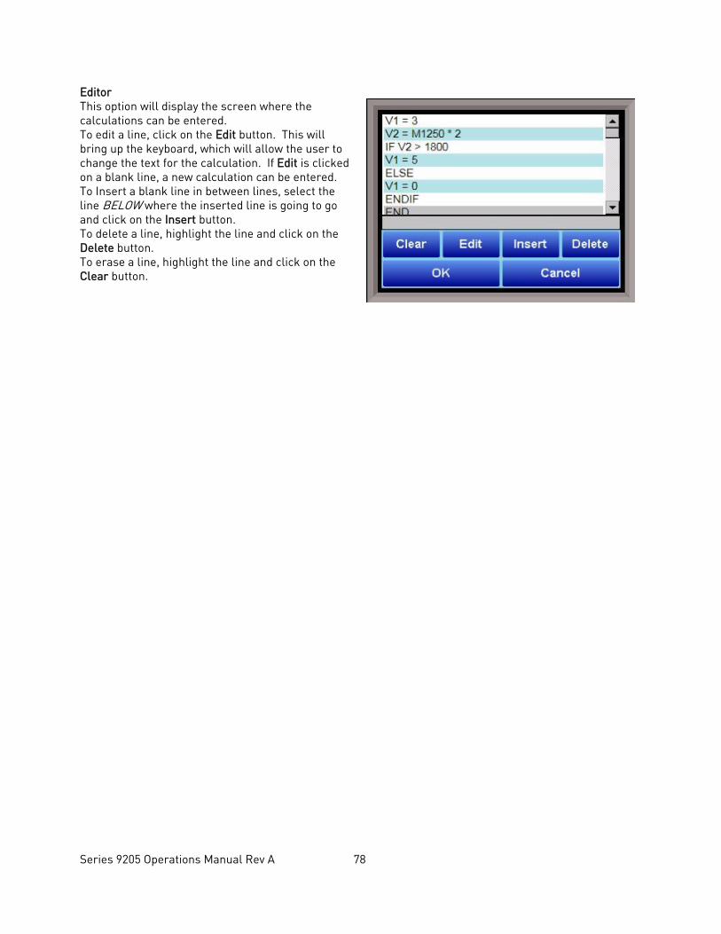
Series 9205 Operations Manual Rev A 78
Editor This option will display the screen where the calculations can be entered. To edit a line, click on the Edit button. This will bring up the keyboard, which will allow the user to change the text for the calculation. If Edit is clicked on a blank line, a new calculation can be entered. To Insert a blank line in between lines, select the line BELOW where the inserted line is going to go and click on the Insert button. To delete a line, highlight the line and click on the Delete button. To erase a line, highlight the line and click on the Clear button.
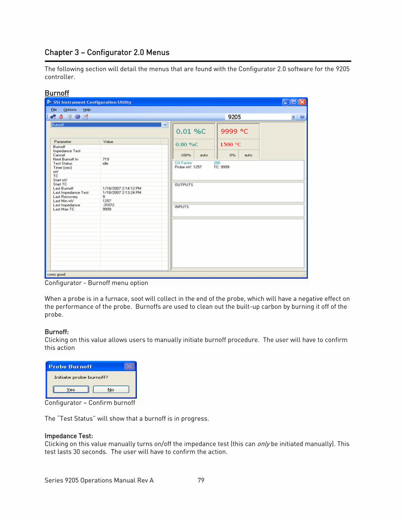
Series 9205 Operations Manual Rev A 79
Chapter 3 – Configurator 2.0 Menus The following section will detail the menus that are found with the Configurator 2.0 software for the 9205 controller. Burnoff
Configurator - Burnoff menu option When a probe is in a furnace, soot will collect in the end of the probe, which will have a negative effect on the performance of the probe. Burnoffs are used to clean out the built-up carbon by burning it off of the probe. Burnoff: Clicking on this value allows users to manually initiate burnoff procedure. The user will have to confirm this action
Configurator – Confirm burnoff The “Test Status” will show that a burnoff is in progress. Impedance Test: Clicking on this value manually turns on/off the impedance test (this can only be initiated manually). This test lasts 30 seconds. The user will have to confirm the action.
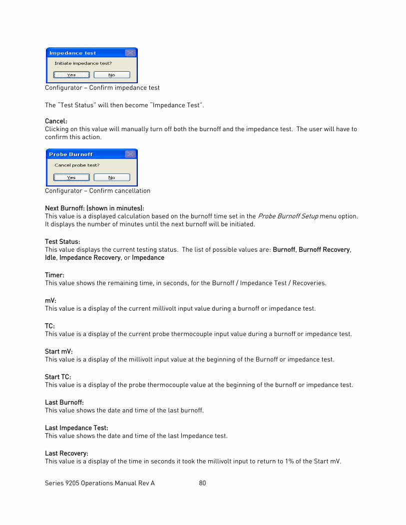
Series 9205 Operations Manual Rev A 80
Configurator – Confirm impedance test The “Test Status” will then become “Impedance Test”. Cancel: Clicking on this value will manually turn off both the burnoff and the impedance test. The user will have to confirm this action.
Configurator – Confirm cancellation Next Burnoff: (shown in minutes): This value is a displayed calculation based on the burnoff time set in the Probe Burnoff Setup menu option. It displays the number of minutes until the next burnoff will be initiated. Test Status: This value displays the current testing status. The list of possible values are: Burnoff, Burnoff Recovery, Idle, Impedance Recovery, or Impedance Timer: This value shows the remaining time, in seconds, for the Burnoff / Impedance Test / Recoveries. mV: This value is a display of the current millivolt input value during a burnoff or impedance test. TC: This value is a display of the current probe thermocouple input value during a burnoff or impedance test. Start mV: This value is a display of the millivolt input value at the beginning of the Burnoff or impedance test. Start TC: This value is a display of the probe thermocouple value at the beginning of the burnoff or impedance test. Last Burnoff: This value shows the date and time of the last burnoff. Last Impedance Test: This value shows the date and time of the last Impedance test. Last Recovery: This value is a display of the time in seconds it took the millivolt input to return to 1% of the Start mV.
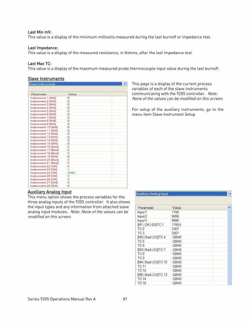
Series 9205 Operations Manual Rev A 81
Last Min mV: This value is a display of the minimum millivolts measured during the last burnoff or impedance test. Last Impedance: This value is a display of the measured resistance, in Kohms, after the last impedance test. Last Max TC: This value is a display of the maximum measured probe thermocouple input value during the last burnoff. Slave Instruments
This page is a display of the current process variables of each of the slave instruments communicating with the 9205 controller. Note: None of the values can be modified on this screen. For setup of the auxiliary instruments, go to the menu item Slave Instrument Setup
Auxiliary Analog Input This menu option shows the process variables for the three analog inputs of the 9205 controller. It also shows the input types and any information from attached slave analog input modules. Note: None of the values can be modified on this screen.
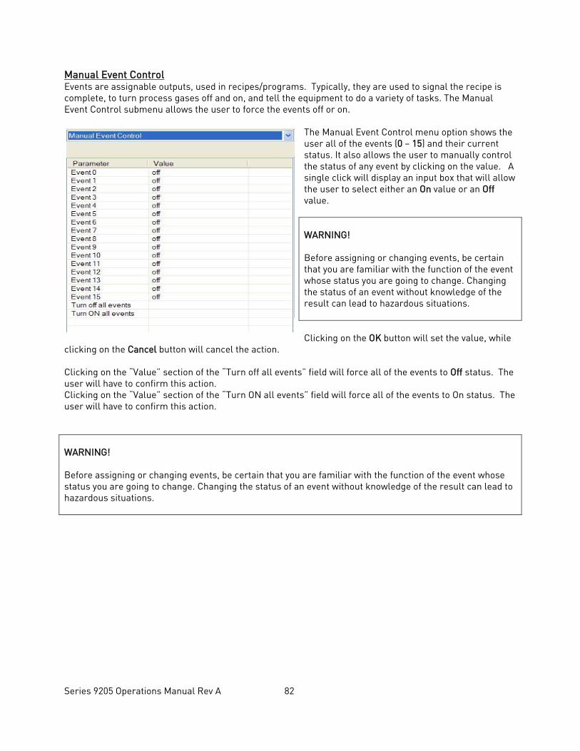
Series 9205 Operations Manual Rev A 82
Manual Event Control Events are assignable outputs, used in recipes/programs. Typically, they are used to signal the recipe is complete, to turn process gases off and on, and tell the equipment to do a variety of tasks. The Manual Event Control submenu allows the user to force the events off or on.
The Manual Event Control menu option shows the user all of the events (0 – 15) and their current status. It also allows the user to manually control the status of any event by clicking on the value. A single click will display an input box that will allow the user to select either an On value or an Off value. WARNING! Before assigning or changing events, be certain that you are familiar with the function of the event whose status you are going to change. Changing the status of an event without knowledge of the result can lead to hazardous situations. Clicking on the OK button will set the value, while
clicking on the Cancel button will cancel the action. Clicking on the “Value” section of the “Turn off all events” field will force all of the events to Off status. The user will have to confirm this action. Clicking on the “Value” section of the “Turn ON all events” field will force all of the events to On status. The user will have to confirm this action. WARNING! Before assigning or changing events, be certain that you are familiar with the function of the event whose status you are going to change. Changing the status of an event without knowledge of the result can lead to hazardous situations.
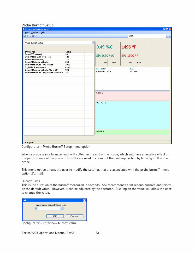
Series 9205 Operations Manual Rev A 83
Probe Burnoff Setup
Configurator – Probe Burnoff Setup menu option When a probe is in a furnace, soot will collect in the end of the probe, which will have a negative effect on the performance of the probe. Burnoffs are used to clean out the built-up carbon by burning it off of the probe. This menu option allows the user to modify the settings that are associated with the probe burnoff (menu option Burnoff). Burnoff Time: This is the duration of the burnoff measured in seconds. SSi recommends a 90 second burnoff, and this will be the default value. However, it can be adjusted by the operator. Clicking on the value will allow the user to change the value.
Configurator – Enter new burnoff value
Series 9205 Operations Manual Rev A 84
Click on the OK button to set the new value, or click on the Cancel button to cancel. Burnoff Recovery Wait Time: The amount of time allotted to allow the probe measurements to return to a stable, accurate range after the burnoff is complete. This is measured in seconds. The control output is held until this time is elapsed. Clicking on the value will allow the user to change the value. Burnoff Interval: This is the amount of time between the beginning of one burnoff and the beginning of the next scheduled burnoff, in minutes. Default time for the instrument is 720 minutes (12 hours). However, the amount of time between burnoffs should be determined by the application. Burnoff Minimum Millivolts: The minimum measured millivolt tolerance of the probe required to start a burnoff. Clicking on the value will allow the user to change the value. SSi recommends the millivolt value gets down to 200 mV. Burnoff Maximum Temperature: The maximum measured temperature allowed during a burnoff. If the temperature value is exceeded the burnoff will stop. This is done to help maintain the life and the accuracy of your probe. SSi recommends a value of 1800 degrees. Clicking on the value will allow the user to change the value. Digital IN 4 Assignment: The value for the digital input 4 assignment. Clicking on the value will allow the user to change the value, which can be either event or start BO. Burnoff Minimum Millivolts Alarm Setpoint: The minimum millivolt value that must be reached in order for the “Insufficient mV drop during BO” alarm not to be generated. If the millivolt value does not drop below the minimum, the alarm will be generated. Burnoff Maximum Temperature Rise Limit: The maximum number of degrees that the temperature is allowed to increase before the “Excessive TC rise during BO” alarm is generated.
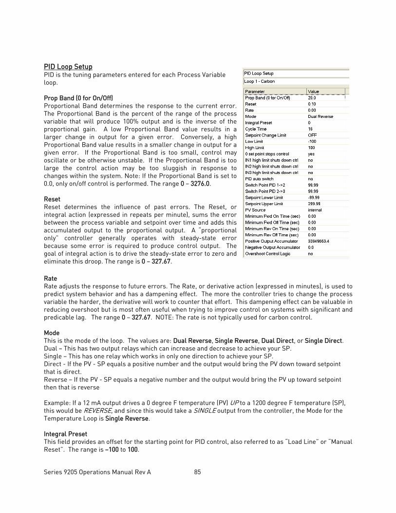
Series 9205 Operations Manual Rev A 85
PID Loop Setup PID is the tuning parameters entered for each Process Variable loop. Prop Band (0 for On/Off) Proportional Band determines the response to the current error. The Proportional Band is the percent of the range of the process variable that will produce 100% output and is the inverse of the proportional gain. A low Proportional Band value results in a larger change in output for a given error. Conversely, a high Proportional Band value results in a smaller change in output for a given error. If the Proportional Band is too small, control may oscillate or be otherwise unstable. If the Proportional Band is too large the control action may be too sluggish in response to changes within the system. Note: If the Proportional Band is set to 0.0, only on/off control is performed. The range 0 – 3276.0. Reset Reset determines the influence of past errors. The Reset, or integral action (expressed in repeats per minute), sums the error between the process variable and setpoint over time and adds this accumulated output to the proportional output. A “proportional only” controller generally operates with steady-state error because some error is required to produce control output. The goal of integral action is to drive the steady-state error to zero and eliminate this droop. The range is 0 – 327.67. Rate Rate adjusts the response to future errors. The Rate, or derivative action (expressed in minutes), is used to predict system behavior and has a dampening effect. The more the controller tries to change the process variable the harder, the derivative will work to counter that effort. This dampening effect can be valuable in reducing overshoot but is most often useful when trying to improve control on systems with significant and predicable lag. The range 0 – 327.67. NOTE: The rate is not typically used for carbon control. Mode This is the mode of the loop. The values are: Dual Reverse, Single Reverse, Dual Direct, or Single Direct. Dual – This has two output relays which can increase and decrease to achieve your SP. Single – This has one relay which works in only one direction to achieve your SP. Direct - If the PV - SP equals a positive number and the output would bring the PV down toward setpoint that is direct. Reverse – If the PV - SP equals a negative number and the output would bring the PV up toward setpoint then that is reverse Example: If a 12 mA output drives a 0 degree F temperature (PV) UP to a 1200 degree F temperature (SP), this would be REVERSE, and since this would take a SINGLE output from the controller, the Mode for the Temperature Loop is Single Reverse. Integral Preset This field provides an offset for the starting point for PID control, also referred to as “Load Line” or “Manual Reset”. The range is –100 to 100.
Series 9205 Operations Manual Rev A 86
Cycle Time This field is typically set to the valve travel time multiplied by 1.5. The range is 0 – 300. Setpoint Change Limit This is a smart time feature that allows Process Loop to use PB only without Reset until the Process Variable drops below the percent output set under this category. It is used to eliminate overshoot. The Output percentage selected under this category must be above the normal operating output percentage of the furnace at heat. The options are: OFF, 80%, 70%, 60%, 50%, 40%, 30%, or 20%. Example: If the furnace runs at 40% output at heat for the maximum load, the setpoint change limit should be set to 60%. Low Limit This is the low limit for the loop. The range is –100 to 100. High Limit This is the high limit for the loop. The range is –100 to 100. 0 Setpoint Stops Control If the Setpoint is zero, then all outputs are turned off. The option is either Yes or No. IN1 high limit shuts down ctrl If input 1’s high limit is reached, then all outputs are turned off. The value can either be Yes or No. IN2 high limit shuts down ctrl If input 2’s high limit is reached, then all outputs are turned off. The value can either be Yes or No. IN3 high limit shuts down ctrl If input 3’s high limit is reached, then all outputs are turned off. The value can either be Yes or No. PID Auto Switch This is the PID auto switch field. The value can either be Yes or No. PID auto switch is a feature within the instrument that allows multiple PID Loops to be used for various temperature ranges. This feature can be extremely helpful when a single PID Loop is not accurate across a wide temperature range. The most common indication that PID auto switching may improve furnace ability is failure to pass Temperature Uniformity Surveys (TUS). In many examples, a certain PID Loop may prevent under- or over-shoot at normal operating temperatures; but produce unacceptable overshoot at lower temperature. This feature allows the user to utilize (up to) three distinct loops to obtain more accurate heating curves. In most applications, it is helpful to use the built-in Tuning Assistant feature to determine appropriate PID values. These values can be recorded and manually entered as described below. The chart below demonstrates this feature.
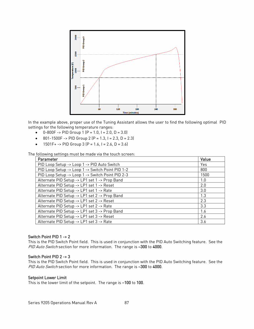
Series 9205 Operations Manual Rev A 87
In the example above, proper use of the Tuning Assistant allows the user to find the following optimal PID settings for the following temperature ranges:
• 0-800F -> PID Group 1 (P = 1.0, I = 2.0, D = 3.0) • 801-1500F -> PID Group 2 (P = 1.3, I = 2.3, D = 2.3) • 1501F+ -> PID Group 3 (P = 1.6, I = 2.6, D = 3.6)
The following settings must be made via the touch screen: Parameter Value PID Loop Setup -> Loop 1 -> PID Auto Switch Yes PID Loop Setup -> Loop 1 -> Switch Point PID 1-2 800 PID Loop Setup -> Loop 1 -> Switch Point PID 2-3 1500 Alternate PID Setup -> LP1 set 1 -> Prop Band 1.0 Alternate PID Setup -> LP1 set 1 -> Reset 2.0 Alternate PID Setup -> LP1 set 1 -> Rate 3.0 Alternate PID Setup -> LP1 set 2 -> Prop Band 1.3 Alternate PID Setup -> LP1 set 2 -> Reset 2.3 Alternate PID Setup -> LP1 set 2 -> Rate 3.3 Alternate PID Setup -> LP1 set 3 -> Prop Band 1.6 Alternate PID Setup -> LP1 set 3 -> Reset 2.6 Alternate PID Setup -> LP1 set 3 -> Rate 3.6
Switch Point PID 1 -> 2 This is the PID Switch Point field. This is used in conjunction with the PID Auto Switching feature. See the PID Auto Switch section for more information. The range is –300 to 4000. Switch Point PID 2 -> 3 This is the PID Switch Point field. This is used in conjunction with the PID Auto Switching feature. See the PID Auto Switch section for more information. The range is –300 to 4000. Setpoint Lower Limit This is the lower limit of the setpoint. The range is –100 to 100.
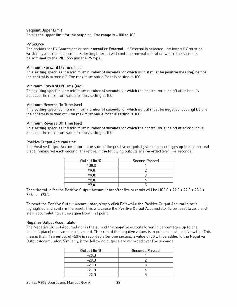
Series 9205 Operations Manual Rev A 88
Setpoint Upper Limit This is the upper limit for the setpoint. The range is –100 to 100. PV Source The options for PV Source are either Internal or External. If External is selected, the loop’s PV must be written by an external source. Selecting Internal will continue normal operation where the source is determined by the PID loop and the PV type. Minimum Forward On Time (sec) This setting specifies the minimum number of seconds for which output must be positive (heating) before the control is turned off. The maximum value for this setting is 100. Minimum Forward Off Time (sec) This setting specifies the minimum number of seconds for which the control must be off after heat is applied. The maximum value for this setting is 100. Minimum Reverse On Time (sec) This setting specifies the minimum number of seconds for which output must be negative (cooling) before the control is turned off. The maximum value for this setting is 100. Minimum Reverse Off Time (sec) This setting specifies the minimum number of seconds for which the control must be off after cooling is applied. The maximum value for this setting is 100. Positive Output Accumulator The Positive Output Accumulator is the sum of the positive outputs (given in percentages up to one decimal place) measured each second. Therefore, if the following outputs are recorded over five seconds:
Output (in %) Second Passed 100.0 1 99.0 2 99.0 3 98.0 4 97.0 5
Then the value for the Positive Output Accumulator after five seconds will be (100.0 + 99.0 + 99.0 + 98.0 + 97.0) or 493.0. To reset the Positive Output Accumulator, simply click Edit while the Positive Output Accumulator is highlighted and confirm the reset. This will cause the Positive Output Accumulator to be reset to zero and start accumulating values again from that point. Negative Output Accumulator The Negative Output Accumulator is the sum of the negative outputs (given in percentages up to one decimal place) measured each second. The sum of the negative values is expressed as a positive value. This means that, if an output of -50% is recorded after one second, a value of 50 will be added to the Negative Output Accumulator. Similarly, if the following outputs are recorded over five seconds:
Output (in %) Seconds Passed -20.0 1 -20.0 2 -21.0 3 -21.0 4 -22.0 5
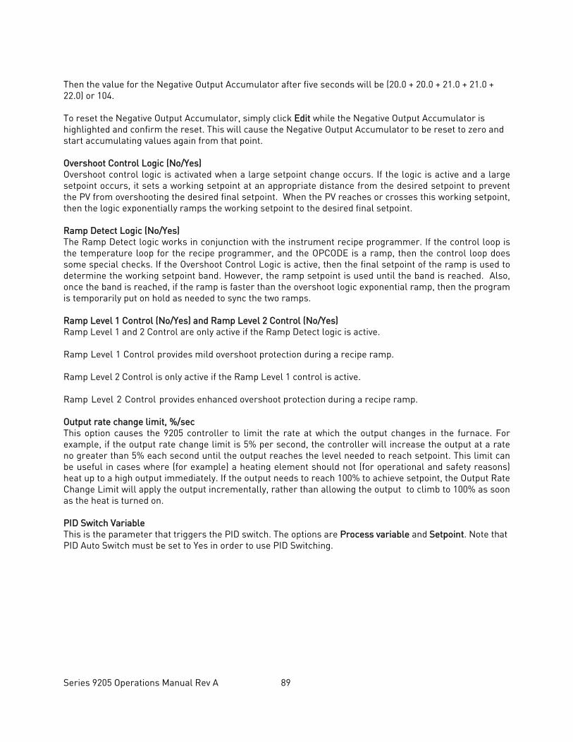
Series 9205 Operations Manual Rev A 89
Then the value for the Negative Output Accumulator after five seconds will be (20.0 + 20.0 + 21.0 + 21.0 + 22.0) or 104. To reset the Negative Output Accumulator, simply click Edit while the Negative Output Accumulator is highlighted and confirm the reset. This will cause the Negative Output Accumulator to be reset to zero and start accumulating values again from that point. Overshoot Control Logic (No/Yes) Overshoot control logic is activated when a large setpoint change occurs. If the logic is active and a large setpoint occurs, it sets a working setpoint at an appropriate distance from the desired setpoint to prevent the PV from overshooting the desired final setpoint. When the PV reaches or crosses this working setpoint, then the logic exponentially ramps the working setpoint to the desired final setpoint. Ramp Detect Logic (No/Yes) The Ramp Detect logic works in conjunction with the instrument recipe programmer. If the control loop is the temperature loop for the recipe programmer, and the OPCODE is a ramp, then the control loop does some special checks. If the Overshoot Control Logic is active, then the final setpoint of the ramp is used to determine the working setpoint band. However, the ramp setpoint is used until the band is reached. Also, once the band is reached, if the ramp is faster than the overshoot logic exponential ramp, then the program is temporarily put on hold as needed to sync the two ramps. Ramp Level 1 Control (No/Yes) and Ramp Level 2 Control (No/Yes) Ramp Level 1 and 2 Control are only active if the Ramp Detect logic is active. Ramp Level 1 Control provides mild overshoot protection during a recipe ramp. Ramp Level 2 Control is only active if the Ramp Level 1 control is active. Ramp Level 2 Control provides enhanced overshoot protection during a recipe ramp. Output rate change limit, %/sec This option causes the 9205 controller to limit the rate at which the output changes in the furnace. For example, if the output rate change limit is 5% per second, the controller will increase the output at a rate no greater than 5% each second until the output reaches the level needed to reach setpoint. This limit can be useful in cases where (for example) a heating element should not (for operational and safety reasons) heat up to a high output immediately. If the output needs to reach 100% to achieve setpoint, the Output Rate Change Limit will apply the output incrementally, rather than allowing the output to climb to 100% as soon as the heat is turned on. PID Switch Variable This is the parameter that triggers the PID switch. The options are Process variable and Setpoint. Note that PID Auto Switch must be set to Yes in order to use PID Switching.
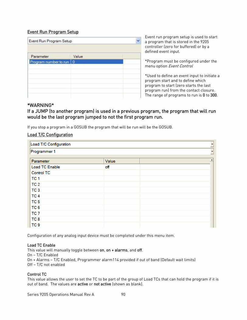
Series 9205 Operations Manual Rev A 90
Event Run Program Setup Event run program setup is used to start a program that is stored in the 9205 controller (zero for buffered) or by a defined event input. *Program must be configured under the menu option Event Control *Used to define an event input to initiate a program start and to define which program to start (zero starts the last program run) from the contact closure. The range of programs to run is 0 to 300.
*WARNING* If a JUMP (to another program) is used in a previous program, the program that will run would be the last program jumped to not the first program run. If you stop a program in a GOSUB the program that will be run will be the GOSUB.
Load T/C Configuration
Configuration of any analog input device must be completed under this menu item. Load TC Enable This value will manually toggle between on, on + alarms, and off. On – T/C Enabled On + Alarms – T/C Enabled, Programmer alarm114 provided if out of band (Default wait limits) Off – T/C not enabled Control TC This value allows the user to set the TC to be part of the group of Load TCs that can hold the program if it is out of band. The values are active or not active (shown as blank).
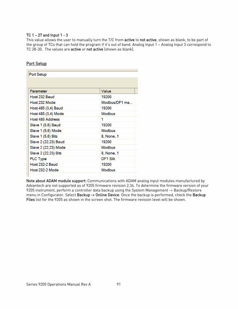
Series 9205 Operations Manual Rev A 91
TC 1 – 27 and Input 1 - 3 This value allows the user to manually turn the T/C from active to not active, shown as blank, to be part of the group of TCs that can hold the program if it’s out of band. Analog Input 1 – Analog Input 3 correspond to TC 28-30. The values are active or not active (shown as blank). Port Setup
Note about ADAM module support: Communications with ADAM analog input modules manufactured by Advantech are not supported as of 9205 firmware revision 2.34. To determine the firmware version of your 9205 instrument, perform a controller data backup using the System Management -> Backup/Restore menu in Configurator. Select Backup -> Online Device. Once the backup is performed, check the Backup Files list for the 9205 as shown in the screen shot. The firmware revision level will be shown.
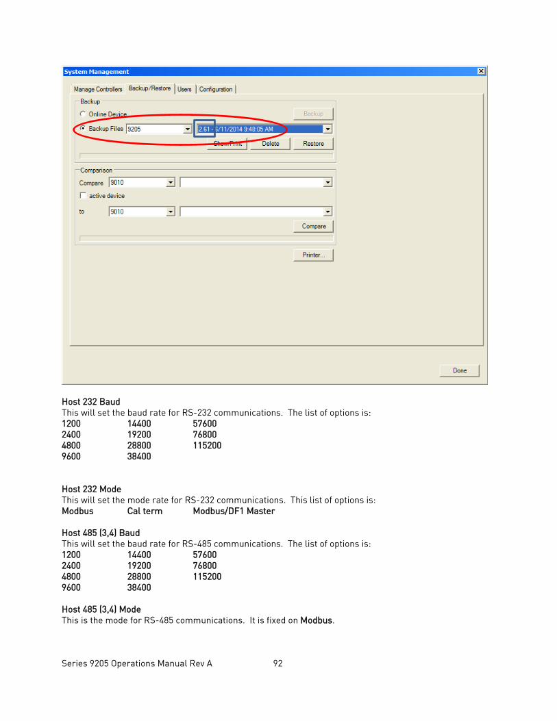
Series 9205 Operations Manual Rev A 92
Host 232 Baud This will set the baud rate for RS-232 communications. The list of options is: 1200 14400 57600 2400 19200 76800 4800 28800 115200 9600 38400 Host 232 Mode This will set the mode rate for RS-232 communications. This list of options is: Modbus Cal term Modbus/DF1 Master Host 485 (3,4) Baud This will set the baud rate for RS-485 communications. The list of options is: 1200 14400 57600 2400 19200 76800 4800 28800 115200 9600 38400 Host 485 (3,4) Mode This is the mode for RS-485 communications. It is fixed on Modbus.
Series 9205 Operations Manual Rev A 93
Host 485 Address This will set the address for RS-485 communications. The range is 1 – 247. Slave 1 (5,6) Baud This will set the baud rate for Slave 1 communications. The list of options is: 1200 14400 57600 2400 19200 76800 4800 28800 115200 9600 38400 Slave 1 (5,6) Mode This will set the mode for Slave 1 communications. The list of options is: Modbus Master Yokogawa Modbus Host Slave 1 (5,6) Bits This will set the data bits, parity, and stop bits (in that order). The list of options is: 8, none, 1 8, odd, 1 8, even, 1 8, none, 2 Slave 2 Baud This will set the baud rate for Slave 2 communications. The list of options is: 1200 14400 57600 2400 19200 76800 4800 28800 115200 9600 38400 Slave 2 Mode This will set the mode for Slave 2 communications. This list of options is: MMI Modbus N/A SSi Analog Input Board Yokogawa Slave 1 (5,6) Bits This will set the data bits, parity, and stop bits (in that order). The list of options is: 8, none, 1 8, odd, 1 8, even, 1 8, none, 2 PLC Type This value defines the type of PLC being used. The options are: Micrologix Modbus, MCMmodule Modbus, DF1 PLC5, DF1 Slik, Passive. Host 232-2 Baud This will set the baud rate for RS-232 communications. The list of options is: 1200 14400 57600 2400 19200 76800 4800 28800 115200
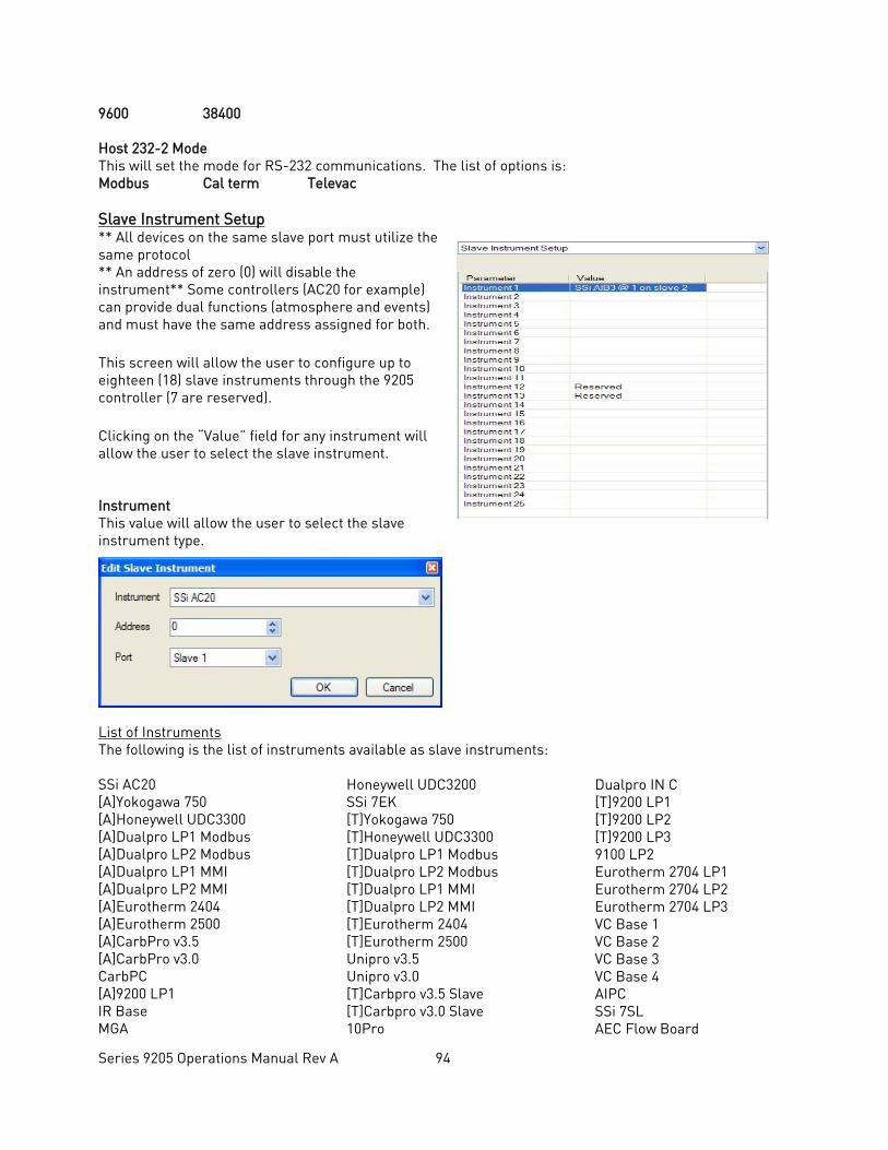
Series 9205 Operations Manual Rev A 94
9600 38400 Host 232-2 Mode This will set the mode for RS-232 communications. The list of options is: Modbus Cal term Televac Slave Instrument Setup ** All devices on the same slave port must utilize the same protocol ** An address of zero (0) will disable the instrument** Some controllers (AC20 for example) can provide dual functions (atmosphere and events) and must have the same address assigned for both. This screen will allow the user to configure up to eighteen (18) slave instruments through the 9205 controller (7 are reserved). Clicking on the “Value” field for any instrument will allow the user to select the slave instrument. Instrument This value will allow the user to select the slave instrument type.
List of Instruments The following is the list of instruments available as slave instruments: SSi AC20 [A]Yokogawa 750 [A]Honeywell UDC3300 [A]Dualpro LP1 Modbus [A]Dualpro LP2 Modbus [A]Dualpro LP1 MMI [A]Dualpro LP2 MMI [A]Eurotherm 2404 [A]Eurotherm 2500 [A]CarbPro v3.5 [A]CarbPro v3.0 CarbPC [A]9200 LP1 IR Base MGA
Honeywell UDC3200 SSi 7EK [T]Yokogawa 750 [T]Honeywell UDC3300 [T]Dualpro LP1 Modbus [T]Dualpro LP2 Modbus [T]Dualpro LP1 MMI [T]Dualpro LP2 MMI [T]Eurotherm 2404 [T]Eurotherm 2500 Unipro v3.5 Unipro v3.0 [T]Carbpro v3.5 Slave [T]Carbpro v3.0 Slave 10Pro
Dualpro IN C [T]9200 LP1 [T]9200 LP2 [T]9200 LP3 9100 LP2 Eurotherm 2704 LP1 Eurotherm 2704 LP2 Eurotherm 2704 LP3 VC Base 1 VC Base 2 VC Base 3 VC Base 4 AIPC SSi 7SL AEC Flow Board
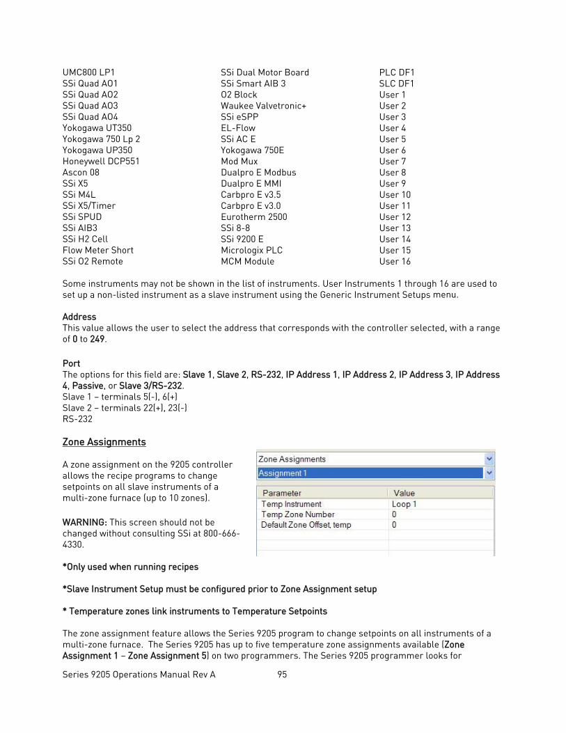
Series 9205 Operations Manual Rev A 95
UMC800 LP1 SSi Quad AO1 SSi Quad AO2 SSi Quad AO3 SSi Quad AO4 Yokogawa UT350 Yokogawa 750 Lp 2 Yokogawa UP350 Honeywell DCP551 Ascon 08 SSi X5 SSi M4L SSi X5/Timer SSi SPUD SSi AIB3 SSi H2 Cell Flow Meter Short SSi O2 Remote
SSi Dual Motor Board SSi Smart AIB 3 O2 Block Waukee Valvetronic+ SSi eSPP EL-Flow SSi AC E Yokogawa 750E Mod Mux Dualpro E Modbus Dualpro E MMI Carbpro E v3.5 Carbpro E v3.0 Eurotherm 2500 SSi 8-8 SSi 9200 E Micrologix PLC MCM Module
PLC DF1 SLC DF1 User 1 User 2 User 3 User 4 User 5 User 6 User 7 User 8 User 9 User 10 User 11 User 12 User 13 User 14 User 15 User 16
Some instruments may not be shown in the list of instruments. User Instruments 1 through 16 are used to set up a non-listed instrument as a slave instrument using the Generic Instrument Setups menu. Address This value allows the user to select the address that corresponds with the controller selected, with a range of 0 to 249. Port The options for this field are: Slave 1, Slave 2, RS-232, IP Address 1, IP Address 2, IP Address 3, IP Address 4, Passive, or Slave 3/RS-232. Slave 1 – terminals 5(-), 6(+) Slave 2 – terminals 22(+), 23(-) RS-232 Zone Assignments A zone assignment on the 9205 controller allows the recipe programs to change setpoints on all slave instruments of a multi-zone furnace (up to 10 zones). WARNING: This screen should not be changed without consulting SSi at 800-666-4330. *Only used when running recipes *Slave Instrument Setup must be configured prior to Zone Assignment setup * Temperature zones link instruments to Temperature Setpoints The zone assignment feature allows the Series 9205 program to change setpoints on all instruments of a multi-zone furnace. The Series 9205 has up to five temperature zone assignments available (Zone Assignment 1 – Zone Assignment 5) on two programmers. The Series 9205 programmer looks for
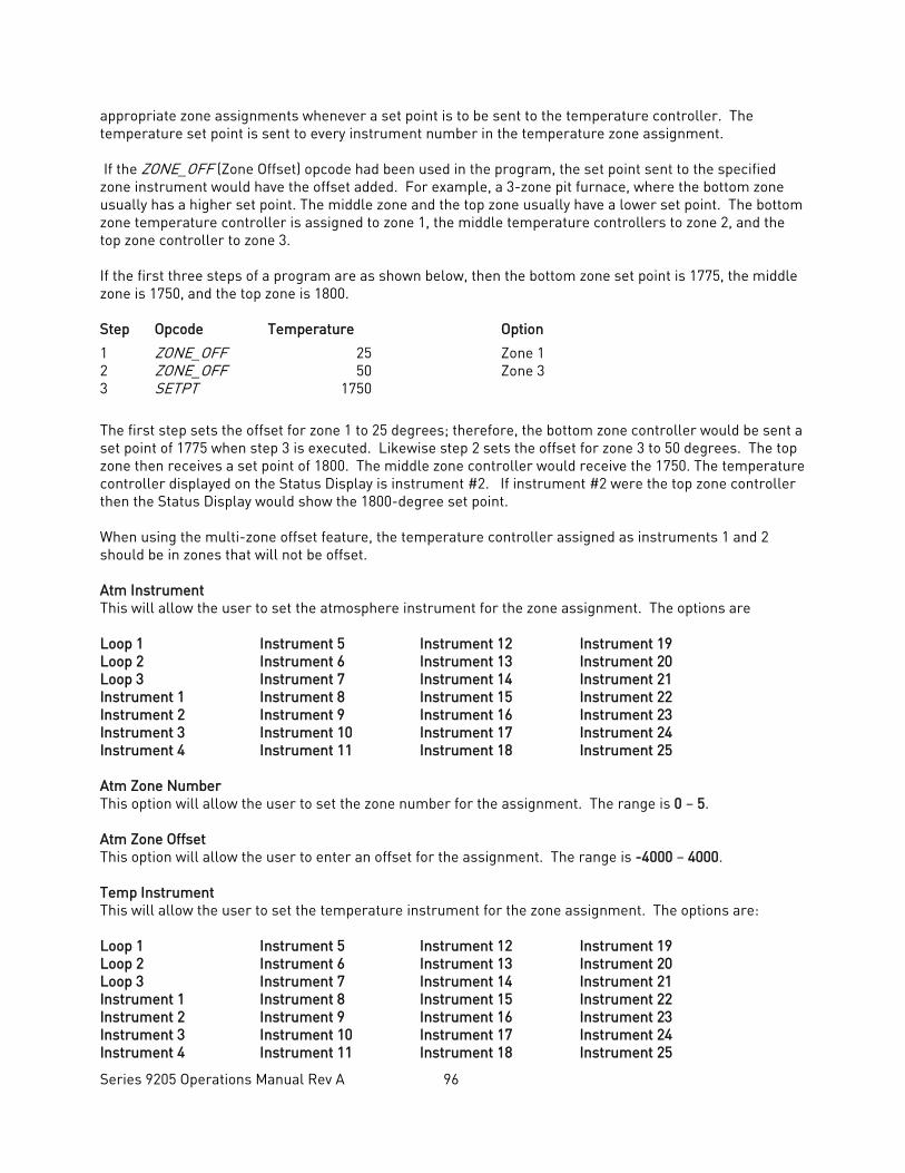
Series 9205 Operations Manual Rev A 96
appropriate zone assignments whenever a set point is to be sent to the temperature controller. The temperature set point is sent to every instrument number in the temperature zone assignment. If the ZONE_OFF (Zone Offset) opcode had been used in the program, the set point sent to the specified zone instrument would have the offset added. For example, a 3-zone pit furnace, where the bottom zone usually has a higher set point. The middle zone and the top zone usually have a lower set point. The bottom zone temperature controller is assigned to zone 1, the middle temperature controllers to zone 2, and the top zone controller to zone 3. If the first three steps of a program are as shown below, then the bottom zone set point is 1775, the middle zone is 1750, and the top zone is 1800. Step Opcode Temperature Option
1 ZONE_OFF 25 Zone 1 2 ZONE_OFF 50 Zone 3 3 SETPT 1750
The first step sets the offset for zone 1 to 25 degrees; therefore, the bottom zone controller would be sent a set point of 1775 when step 3 is executed. Likewise step 2 sets the offset for zone 3 to 50 degrees. The top zone then receives a set point of 1800. The middle zone controller would receive the 1750. The temperature controller displayed on the Status Display is instrument #2. If instrument #2 were the top zone controller then the Status Display would show the 1800-degree set point. When using the multi-zone offset feature, the temperature controller assigned as instruments 1 and 2 should be in zones that will not be offset. Atm Instrument This will allow the user to set the atmosphere instrument for the zone assignment. The options are Loop 1 Instrument 5 Instrument 12 Instrument 19 Loop 2 Instrument 6 Instrument 13 Instrument 20 Loop 3 Instrument 7 Instrument 14 Instrument 21 Instrument 1 Instrument 8 Instrument 15 Instrument 22 Instrument 2 Instrument 9 Instrument 16 Instrument 23 Instrument 3 Instrument 10 Instrument 17 Instrument 24 Instrument 4 Instrument 11 Instrument 18 Instrument 25 Atm Zone Number This option will allow the user to set the zone number for the assignment. The range is 0 – 5. Atm Zone Offset This option will allow the user to enter an offset for the assignment. The range is -4000 – 4000. Temp Instrument This will allow the user to set the temperature instrument for the zone assignment. The options are: Loop 1 Instrument 5 Instrument 12 Instrument 19 Loop 2 Instrument 6 Instrument 13 Instrument 20 Loop 3 Instrument 7 Instrument 14 Instrument 21 Instrument 1 Instrument 8 Instrument 15 Instrument 22 Instrument 2 Instrument 9 Instrument 16 Instrument 23 Instrument 3 Instrument 10 Instrument 17 Instrument 24 Instrument 4 Instrument 11 Instrument 18 Instrument 25
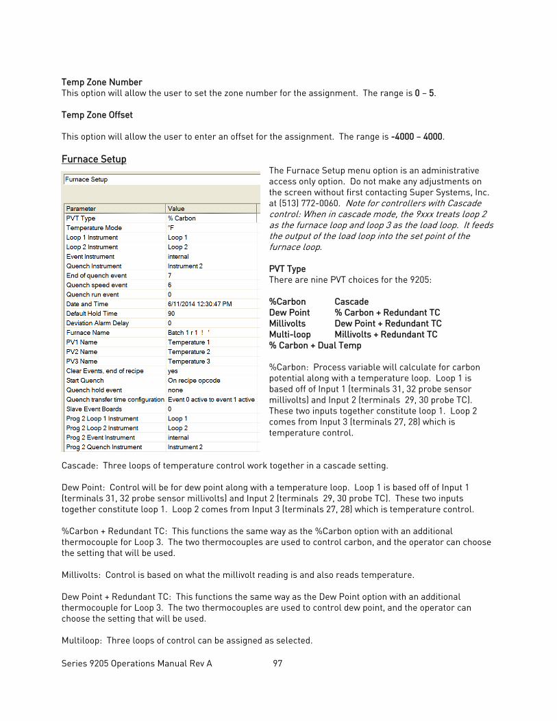
Series 9205 Operations Manual Rev A 97
Temp Zone Number This option will allow the user to set the zone number for the assignment. The range is 0 – 5. Temp Zone Offset
This option will allow the user to enter an offset for the assignment. The range is -4000 – 4000. Furnace Setup
The Furnace Setup menu option is an administrative access only option. Do not make any adjustments on the screen without first contacting Super Systems, Inc. at (513) 772-0060. Note for controllers with Cascade control: When in cascade mode, the 9xxx treats loop 2 as the furnace loop and loop 3 as the load loop. It feeds the output of the load loop into the set point of the furnace loop. PVT Type There are nine PVT choices for the 9205: %Carbon Cascade Dew Point % Carbon + Redundant TC Millivolts Dew Point + Redundant TC Multi-loop Millivolts + Redundant TC % Carbon + Dual Temp %Carbon: Process variable will calculate for carbon potential along with a temperature loop. Loop 1 is based off of Input 1 (terminals 31, 32 probe sensor millivolts) and Input 2 (terminals 29, 30 probe TC). These two inputs together constitute loop 1. Loop 2 comes from Input 3 (terminals 27, 28) which is temperature control.
Cascade: Three loops of temperature control work together in a cascade setting. Dew Point: Control will be for dew point along with a temperature loop. Loop 1 is based off of Input 1 (terminals 31, 32 probe sensor millivolts) and Input 2 (terminals 29, 30 probe TC). These two inputs together constitute loop 1. Loop 2 comes from Input 3 (terminals 27, 28) which is temperature control. %Carbon + Redundant TC: This functions the same way as the %Carbon option with an additional thermocouple for Loop 3. The two thermocouples are used to control carbon, and the operator can choose the setting that will be used. Millivolts: Control is based on what the millivolt reading is and also reads temperature. Dew Point + Redundant TC: This functions the same way as the Dew Point option with an additional thermocouple for Loop 3. The two thermocouples are used to control dew point, and the operator can choose the setting that will be used. Multiloop: Three loops of control can be assigned as selected.
Series 9205 Operations Manual Rev A 98
Millivolts + Redundant TC: Control is based off of the millivolt reading and also reads temperature. Loop 3 is another thermocouple. %Carbon + Dual Temp: This functions similarly to %Carbon. Input 2 is the control TC. IT is not used to calculate carbon potential with input one and to control furnace temperature. Input 3 in the third loop and is another TC. IMPORTANT: If the 9205 is controlling % Carbon or Dew Point, control will be disabled if either or both of the following are true:
• Millivolts registered by probe are below 500 mV or above 1300 mV. • Temperature registered by probe is below 900°F or above 2100°F.
Temperature Mode
This allows the operator to choose either degree Fahrenheit or Celsius for the temperature. The options are °C or °F. Pressing OK will set the choice. Loop 1 Instrument Internal Loop 1 (typical) Instrument 5 Instrument 12 Instrument 19 Internal Loop 2 Instrument 6 Instrument 13 Instrument 20 Internal Loop 3 Instrument 7 Instrument 14 Instrument 21 Instrument 1 Instrument 8 Instrument 15 Instrument 22 Instrument 2 Instrument 9 Instrument 16 Instrument 23 Instrument 3 Instrument 10 Instrument 17 Instrument 24 Instrument 4 Instrument 11 Instrument 18 Instrument 25 Loop 2 Instrument Internal Loop 1 Instrument 5 Instrument 12 Instrument 19 Internal Loop 2 (typical) Instrument 6 Instrument 13 Instrument 20 Internal Loop 3 Instrument 7 Instrument 14 Instrument 21 Instrument 1 Instrument 8 Instrument 15 Instrument 22 Instrument 2 Instrument 9 Instrument 16 Instrument 23 Instrument 3 Instrument 10 Instrument 17 Instrument 24 Instrument 4 Instrument 11 Instrument 18 Instrument 25 Event Instrument Allows for a slave instrument (or internal) to be the defined event control device. The types of instruments are: Internal, Instrument 1 – Instrument 25. Internal is typical. Quench Instrument Allows for slave instrument (or internal) to be the defined quench control device. The types of instruments are: Internal Loop 1 – Internal Loop 3, Instrument 1 – Instrument 25. End of Quench Event Tells the programmer which event to signal end of quench (related to which relay it is assigned). The default event for this is Event 7, but it can be changed in the furnace setup menu. This event turns on for one (1) minute when the quench timer is complete. The list of possible values is: 0 – 14.
Series 9205 Operations Manual Rev A 99
Quench Speed Event Tells the programmer which event will signal the quench speed. The list of possible values is: 0 – 14. Quench Run Event Tells the programmer which event will signal quench run. The list of possible values is: 0 – 14. Date and Time This value is the current date and time on the 9205 controller only (not the local computer or the touch screen, if applicable). The time on the controller is displayed in the 24-hour format, so 8 = 8 AM, and 14 = 2 PM. Note: The date and time of the touch screen can be changed (if necessary) by selecting the date and time in the lower right corner on the touch screen, once the screen software has been shut down and the Windows™ desktop is visible. Then, at the CE screen the date and time can be changed by double taping the time in the bottom right corner and setting it, then select “apply”. For this to take effect the screen needs to be rebooted; on the older TPC 642 displays the registry needs to be saved under TPC Configuration icon, the Misc Tab and then reboot the touch screen. The date and time that is recorded on the flash card (and therefore the datalog data) is the date and time of the Advantech display, not the controller. Cascade Inhibit Note: This field is only applicable if the controller is in Cascade mode. This will turn cascade control on or off. When inhibit = enabled, the 9205 functions as a multi-loop controller with three control loops. The options are: enabled or disabled. PV Difference Cutback Note: This field is only applicable if the controller is in Cascade Mode. This is used with the Cascade Lower Range EOPV and Cascade Upper Range EOPV to limit the absolute % output of the furnace loop. This will turn the PV difference cutback feature on or off. The options are: enabled or disabled. Cascade Lower Range EOPV Note: This field is only applicable if the controller is in Cascade Mode. This is the cascade lower range end of PV difference. This is used with the PV Difference Cutback and Cascade Upper Range EOPV to limit the absolute % output of the furnace loop. Between the lower range EPOV and the upper range EOPV, there is a linear interpolation from 0 to the loop 2 output maximum (usually 100 %) that determines the maximum % output for the furnace loop. The range is -300 to 10000. Cascade Upper Range EOPV Note: This field is only applicable if the controller is in Cascade Mode. This is the cascade upper range end of PV difference. This is used with the Cascade Lower Range EOPV and PV Difference Cutback to limit the absolute % output of the furnace loop. Between the lower range EPOV and the upper range EOPV, there is a linear interpolation from 0 to the loop 2 output maximum (usually 100 %) that determines the maximum % output for the furnace loop. The range is -300 to 10000. Example: With the Lower EOPV set to 10 and the Upper EOPV set to 110, if the load PV is 1700 and the furnace PV is 1710, the full 100% output is available. If the load PV is 1600 and the furnace PV is 1710, the furnace output will not go above 0%. If the load PV is 1655 and the furnace PV is 1710, the maximum output for the furnace loop will be limited to 55%: (1710 – 1655)/(110-10) * (1.0). Default Hold Time This value is the default holding time for the furnace. The range is 0 to 10000. Deviation Alarm delay This value is the delay for the alarm if a deviation alarm is detected. The range is 0 to 10000.
Series 9205 Operations Manual Rev A 100
Furnace Name This will allow the user to give the controller a display name. PV1 Name This will allow the user to give the first process variable a display name. PV2 Name This will allow the user to give the second process variable a display name PV3 Name This will allow the user to give the third process variable a display name Clear events, end of recipe This switch will allow the user to clear the events out at the end of a recipe. The options are either no or yes. Start Quench This option will determine what event starts the quench cycle. The options are: On Recipe Opcode (QUENCH Opcode), Input 1 – Input 31. Quench Hold Event This option will determine which event will hold the quench cycle. The list of possible values is: 0 – 15. Quench Transfer Time Configuration This option will allow the user to set what will trigger the transfer from the quench cycle. The options are: Event 2 Active Time, or Event 1 Active to Event 2 Active. Slave Event Boards This is the number of slaved boards connected to the 9205. Examples of compatible devices would be a 9015 event module or digital I/O boards connected via an SSi SR box. Prog 2 Loop 1 Instrument This option sets up a selected instrument as the primary atmosphere control for programmer 2. The options are Instrument 1 - 25, or internal loop 1 - 3. When an instrument is set up as the atmosphere control source, the 9205 uses the Slave Instrument as configured in Slave Instrument Setup. When an internal loop is set up as the source, the 9205 uses a corresponding internal PID loop. Prog 2 Loop 2 Instrument This option sets up a selected instrument as the primary temperature control for programmer 2. The options are Instrument 1 - 25, or internal loop 1 - 3. When an instrument is set up as the temperature control source, the 9205 uses the Slave Instrument as configured in Slave Instrument Setup. When an internal loop is set up as the source, the 9205 uses a corresponding internal PID loop. Prog 2 Event Instrument This option sets up the instrument to which the output events are sent and from which the input events are read. Prog 2 Quench Instrument This option sets up the instrument that controls the temperature of the quench bath. Prog 2 End of quench event This option sets the event number that becomes active when the quench timer has timed out. The list of possible values is: 0 – 14.
Series 9205 Operations Manual Rev A 101
Prog 2 Quench speed event This option sets the event number that, when active, causes the quench speed to go to “high.” For example, if the option is set to 1, and event 1 is active, then the quench speed will be set to “high.” See the QUENCH opcode for more details. The list of possible values is: 0 – 14. Prog 2 Quench run event Tells the programmer which event will signal quench run. The default event for this is 0. This event will stay on when the quench timer is timing. The list of possible values is: 0 – 14. Prog 2 Default Hold Time This value is the default maximum hold time, in minutes, for the furnace. If there is a furnace program in hold, this is the amount of time the furnace may stay in hold before an alarm sounds. The range is 0 - 10000. Prog 2 Deviation Alarm Delay This value is the amount of time, in seconds, that a delay will occur before a deviation alarm is generated. The range is 0 - 10000. Prog 2 Clear Events, end of recipe This setting determines whether events are cleared when Programmer 2 is finished running a recipe. Possible values are yes or no. The Quench events are not affected by this selection. Prog 2 Start Quench This setting determines which input event will trigger the beginning of a quench, or whether the quench is triggered by a recipe opcode. Possible values are On recipe opcode, Input 1 – 31. Prog 2 Quench hold event Tells the programmer which event will signal a hold on the quench cycle. The list of possible values is: none, Input 0 – 14. Furnace transfer logic enable This feature is used for furnaces that have two chambers in which a separate recipe programs are running. With this logic enabled, the recipe program and information in Programmer 1 will be transferred to Programmer 2 when the transfer signal is received on digital input 3. Possible values are no or yes. Programmer PV Select This option allows the user to select whether the programmer will use the Process Variable or the Calculated Process Variable as the source variable if loop 1 is controlling % Carbon or temperature. Quench Idle Speed This value determines the output percentage when the quench is idle. Possible values are 0.00 - 100.0% COF Matrix The COF Matrix allows you to configure different CO Factors based on atmosphere and temperature ranges. Up to 8 different matrices (tables) can be configured. COF Table This setting determines which COF Table (set up under the COF Matrix menu) is used by the 9205 to set the current CO Factor. Possible values are 0 (disabled) – 8. COF Restore value This is the CO Factor that is applied when the COF Table is disabled. The range is 0 -1000.
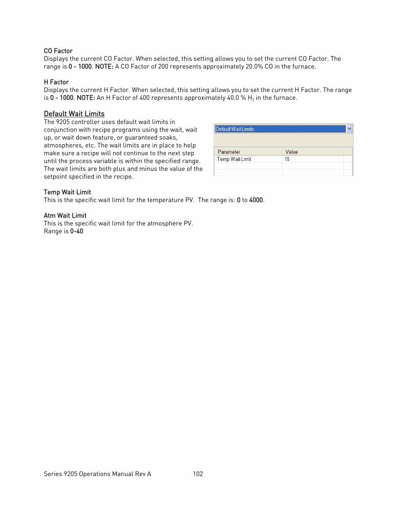
Series 9205 Operations Manual Rev A 102
CO Factor Displays the current CO Factor. When selected, this setting allows you to set the current CO Factor. The range is 0 - 1000. NOTE: A CO Factor of 200 represents approximately 20.0% CO in the furnace. H Factor Displays the current H Factor. When selected, this setting allows you to set the current H Factor. The range is 0 - 1000. NOTE: An H Factor of 400 represents approximately 40.0 % H2 in the furnace. Default Wait Limits The 9205 controller uses default wait limits in conjunction with recipe programs using the wait, wait up, or wait down feature, or guaranteed soaks, atmospheres, etc. The wait limits are in place to help make sure a recipe will not continue to the next step until the process variable is within the specified range. The wait limits are both plus and minus the value of the setpoint specified in the recipe. Temp Wait Limit This is the specific wait limit for the temperature PV. The range is: 0 to 4000. Atm Wait Limit This is the specific wait limit for the atmosphere PV. Range is 0-40
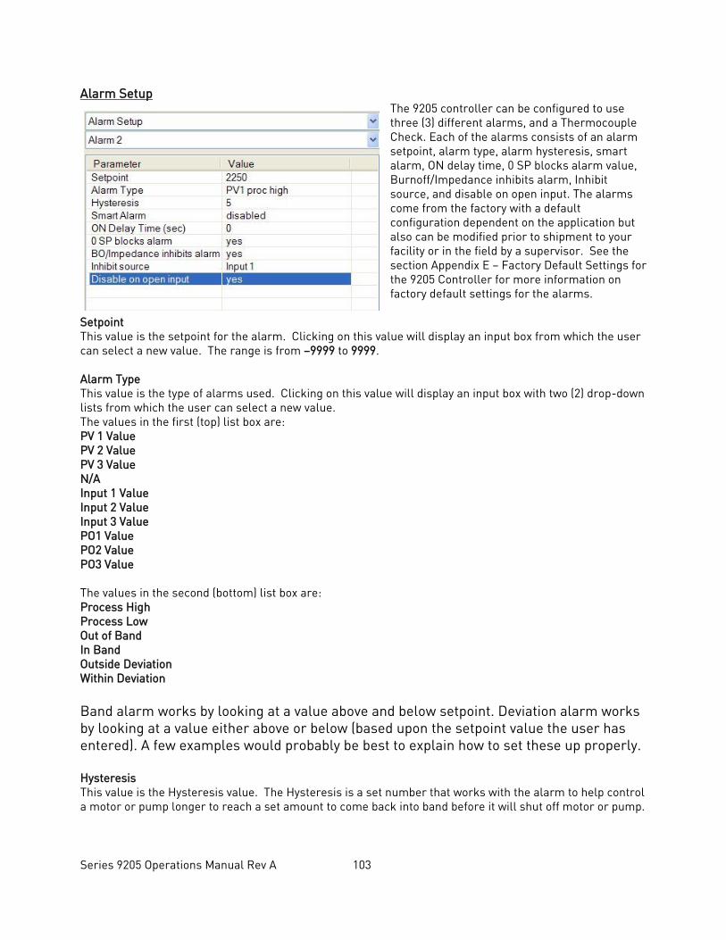
Series 9205 Operations Manual Rev A 103
Alarm Setup The 9205 controller can be configured to use three (3) different alarms, and a Thermocouple Check. Each of the alarms consists of an alarm setpoint, alarm type, alarm hysteresis, smart alarm, ON delay time, 0 SP blocks alarm value, Burnoff/Impedance inhibits alarm, Inhibit source, and disable on open input. The alarms come from the factory with a default configuration dependent on the application but also can be modified prior to shipment to your facility or in the field by a supervisor. See the section Appendix E – Factory Default Settings for the 9205 Controller for more information on factory default settings for the alarms.
Setpoint This value is the setpoint for the alarm. Clicking on this value will display an input box from which the user can select a new value. The range is from –9999 to 9999. Alarm Type This value is the type of alarms used. Clicking on this value will display an input box with two (2) drop-down lists from which the user can select a new value. The values in the first (top) list box are: PV 1 Value PV 2 Value PV 3 Value N/A Input 1 Value Input 2 Value Input 3 Value PO1 Value PO2 Value PO3 Value The values in the second (bottom) list box are: Process High Process Low Out of Band In Band Outside Deviation Within Deviation Band alarm works by looking at a value above and below setpoint. Deviation alarm works by looking at a value either above or below (based upon the setpoint value the user has entered). A few examples would probably be best to explain how to set these up properly. Hysteresis This value is the Hysteresis value. The Hysteresis is a set number that works with the alarm to help control a motor or pump longer to reach a set amount to come back into band before it will shut off motor or pump.
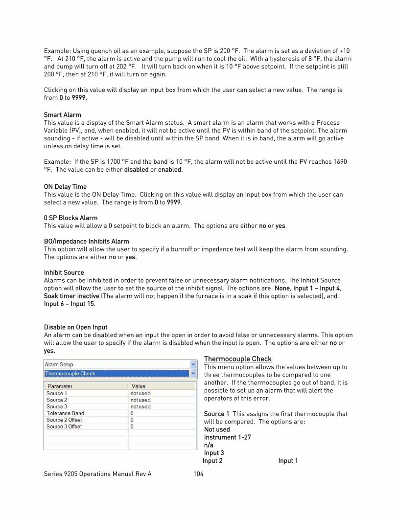
Series 9205 Operations Manual Rev A 104
Example: Using quench oil as an example, suppose the SP is 200 °F. The alarm is set as a deviation of +10 °F. At 210 °F, the alarm is active and the pump will run to cool the oil. With a hysteresis of 8 °F, the alarm and pump will turn off at 202 °F. It will turn back on when it is 10 °F above setpoint. If the setpoint is still 200 °F, then at 210 °F, it will turn on again. Clicking on this value will display an input box from which the user can select a new value. The range is from 0 to 9999. Smart Alarm This value is a display of the Smart Alarm status. A smart alarm is an alarm that works with a Process Variable (PV), and, when enabled, it will not be active until the PV is within band of the setpoint. The alarm sounding - if active - will be disabled until within the SP band. When it is in band, the alarm will go active unless on delay time is set. Example: If the SP is 1700 °F and the band is 10 °F, the alarm will not be active until the PV reaches 1690 °F. The value can be either disabled or enabled. ON Delay Time This value is the ON Delay Time. Clicking on this value will display an input box from which the user can select a new value. The range is from 0 to 9999. 0 SP Blocks Alarm This value will allow a 0 setpoint to block an alarm. The options are either no or yes. BO/Impedance Inhibits Alarm This option will allow the user to specify if a burnoff or impedance test will keep the alarm from sounding. The options are either no or yes. Inhibit Source Alarms can be inhibited in order to prevent false or unnecessary alarm notifications. The Inhibit Source option will allow the user to set the source of the inhibit signal. The options are: None, Input 1 – Input 4, Soak timer inactive (The alarm will not happen if the furnace is in a soak if this option is selected), and . Input 6 – Input 15. Disable on Open Input An alarm can be disabled when an input the open in order to avoid false or unnecessary alarms. This option will allow the user to specify if the alarm is disabled when the input is open. The options are either no or yes.
Thermocouple Check This menu option allows the values between up to three thermocouples to be compared to one another. If the thermocouples go out of band, it is possible to set up an alarm that will alert the operators of this error. Source 1 This assigns the first thermocouple that will be compared. The options are: Not used Instrument 1-27 n/a Input 3
Input 2 Input 1
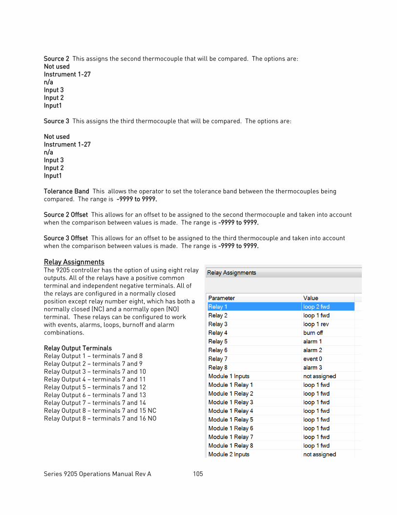
Series 9205 Operations Manual Rev A 105
Source 2 This assigns the second thermocouple that will be compared. The options are: Not used Instrument 1-27 n/a Input 3 Input 2 Input1 Source 3 This assigns the third thermocouple that will be compared. The options are:
Not used Instrument 1-27 n/a Input 3 Input 2 Input1 Tolerance Band This allows the operator to set the tolerance band between the thermocouples being compared. The range is -9999 to 9999. Source 2 Offset This allows for an offset to be assigned to the second thermocouple and taken into account when the comparison between values is made. The range is -9999 to 9999. Source 3 Offset This allows for an offset to be assigned to the third thermocouple and taken into account when the comparison between values is made. The range is -9999 to 9999. Relay Assignments The 9205 controller has the option of using eight relay outputs. All of the relays have a positive common terminal and independent negative terminals. All of the relays are configured in a normally closed position except relay number eight, which has both a normally closed (NC) and a normally open (NO) terminal. These relays can be configured to work with events, alarms, loops, burnoff and alarm combinations. Relay Output Terminals Relay Output 1 – terminals 7 and 8 Relay Output 2 – terminals 7 and 9 Relay Output 3 – terminals 7 and 10 Relay Output 4 – terminals 7 and 11 Relay Output 5 – terminals 7 and 12 Relay Output 6 – terminals 7 and 13 Relay Output 7 – terminals 7 and 14 Relay Output 8 – terminals 7 and 15 NC Relay Output 8 – terminals 7 and 16 NO
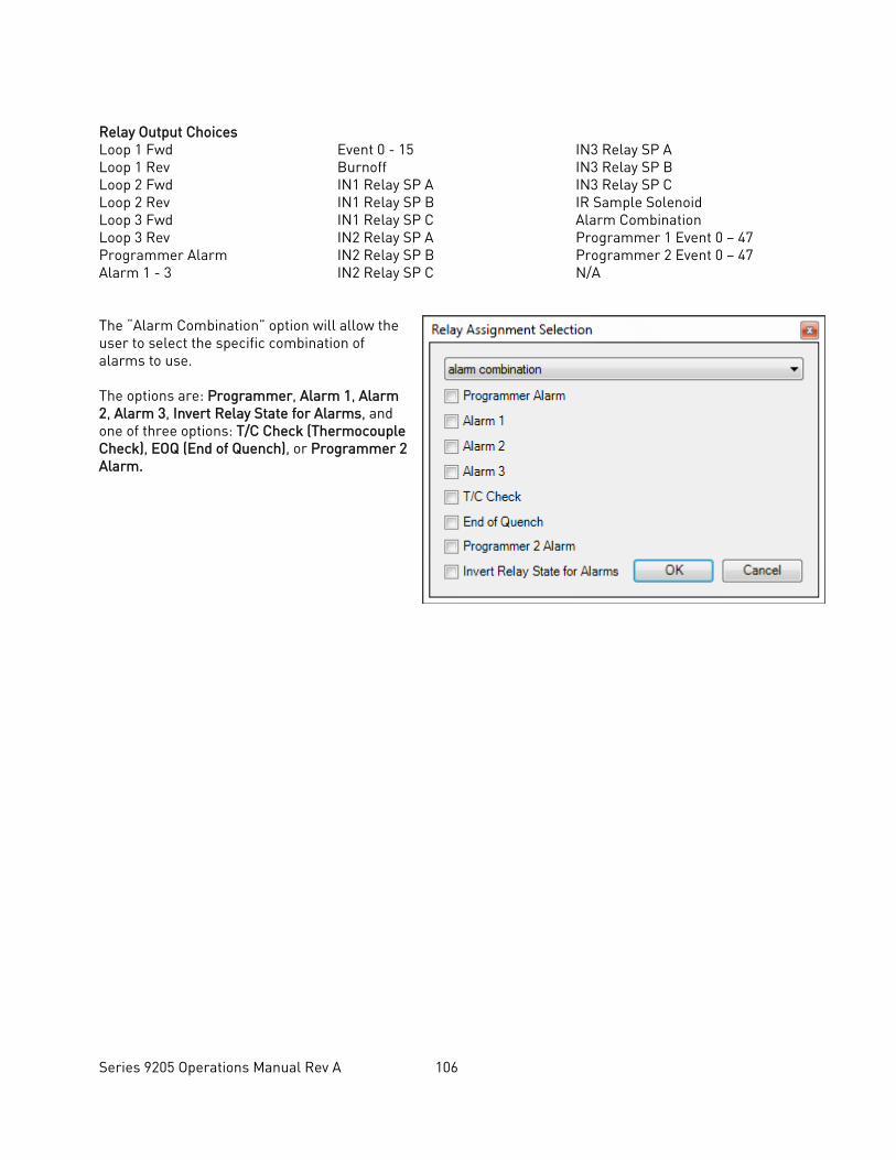
Series 9205 Operations Manual Rev A 106
Relay Output Choices Loop 1 Fwd Loop 1 Rev Loop 2 Fwd Loop 2 Rev Loop 3 Fwd Loop 3 Rev Programmer Alarm Alarm 1 - 3
Event 0 - 15 Burnoff IN1 Relay SP A IN1 Relay SP B IN1 Relay SP C IN2 Relay SP A IN2 Relay SP B IN2 Relay SP C
IN3 Relay SP A IN3 Relay SP B IN3 Relay SP C IR Sample Solenoid Alarm Combination Programmer 1 Event 0 – 47 Programmer 2 Event 0 – 47 N/A
The “Alarm Combination” option will allow the user to select the specific combination of alarms to use. The options are: Programmer, Alarm 1, Alarm 2, Alarm 3, Invert Relay State for Alarms, and one of three options: T/C Check (Thermocouple Check), EOQ (End of Quench), or Programmer 2 Alarm.
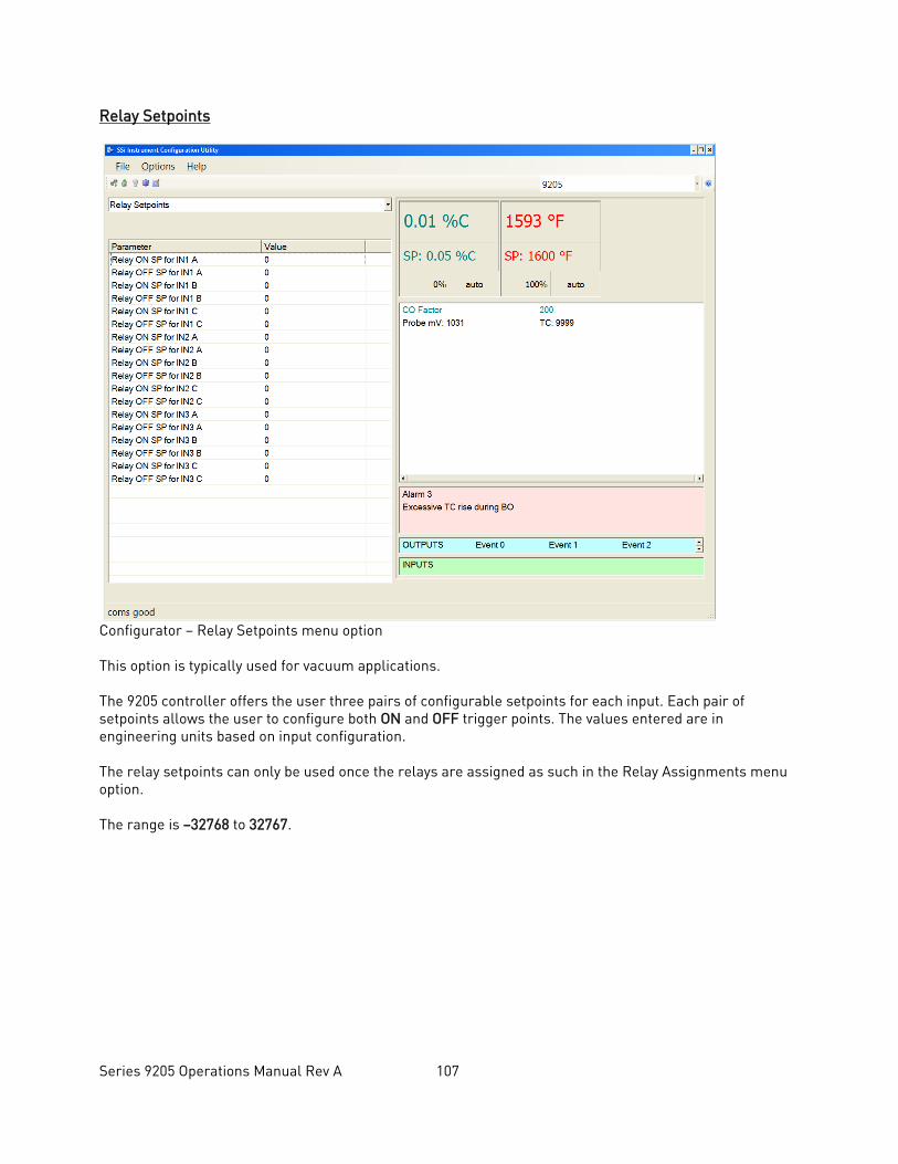
Series 9205 Operations Manual Rev A 107
Relay Setpoints
Configurator – Relay Setpoints menu option This option is typically used for vacuum applications. The 9205 controller offers the user three pairs of configurable setpoints for each input. Each pair of setpoints allows the user to configure both ON and OFF trigger points. The values entered are in engineering units based on input configuration. The relay setpoints can only be used once the relays are assigned as such in the Relay Assignments menu option. The range is –32768 to 32767.
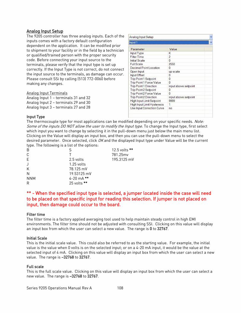
Series 9205 Operations Manual Rev A 108
Analog Input Setup The 9205 controller has three analog inputs. Each of the inputs comes with a factory default configuration dependent on the application. It can be modified prior to shipment to your facility or in the field by a technician or qualified/trained person with the proper security code. Before connecting your input source to the terminals, please verify that the input type is set up correctly. If the Input Type is not correct, do not connect the input source to the terminals, as damage can occur. Please consult SSi by calling (513) 772-0060 before making any changes. Analog Input Terminals Analog Input 1 – terminals 31 and 32 Analog Input 2 – terminals 29 and 30 Analog Input 3 – terminals 27 and 28 Input Type The thermocouple type for most applications can be modified depending on your specific needs. Note: Some of the inputs DO NOT allow the user to modify the Input type. To change the Input type, first select which input you want to change by selecting it in the pull-down menu just below the main menu list. Clicking on the Value will display an input box, and then you can use the pull-down menu to select the desired parameter. Once selected, click OK and the displayed Input type under Value will be the current type. The following is a list of the options: B S 12.5 volts ** C T 781.25mv E 2.5 volts 195.3125 mV J 1.25 volts K 78.125 mV N 19.53125 mV NNM 4-20 mA ** R 25 volts ** ** - When the specified input type is selected, a jumper located inside the case will need to be placed on that specific input for reading this selection. If jumper is not placed on input, then damage could occur to the board. Filter time The filter time is a factory applied averaging tool used to help maintain steady control in high EMI environments. The filter time should not be adjusted with consulting SSI. Clicking on this value will display an input box from which the user can select a new value. The range is 0 to 32767. Initial Scale This is the initial scale value. This could also be referred to as the starting value. For example, the initial value is the value when 0 volts is on the selected input; or on a 4-20 mA input, it would be the value at the selected input of 4 mA. Clicking on this value will display an input box from which the user can select a new value. The range is –32768 to 32767. Full scale This is the full scale value. Clicking on this value will display an input box from which the user can select a new value. The range is –32768 to 32767.
Series 9205 Operations Manual Rev A 109
Decimal Point Location This is the decimal point location value. This will affect the PV value and the location of the decimal when it is displayed. Clicking on this value will display an input box from which the user can select a new value. The range is 0 to 4. Open Input This is the open TC value. Clicking on this value will toggle between up scale, down scale, one trip point, and two trip points. Input Offset The input offset value is algebraically added to the input value to adjust the input curve on read-out. The range is –5000 to 5000. TRIP POINT EXPLANATION Setting a trip point will force the value that the controller uses for calculations to a certain value as assigned by the operator. Once the Trip Point Setpoint is reached, the controller will begin reading the value as the Trip Point Force Value, regardless of what the actual value is inside the furnace. The Trip Point Direction allows the operator to choose whether the controller will alter its reading when the trip point is either above or below the setpoint. Trip Point 1 Setpoint This is the trip point 1 setpoint value in °F. The trip point is used as a way to ensure that the probe is still working properly and that there is not a problem with the furnace that could ruin the load. If the probe takes a measurement in conflict with the trip point, the reading will automatically be forced to the Trip Point Force Value. This will cause the system to set off an alarm so that the operator will be aware there is a problem. The range is –32768 to 32768. Trip Point 1 Force Value This is the trip point 1 force value. This value is used when the probe begins reading values in conflict with the trip point. Although the probe will still be taking measurements, the 9205 controller will use the force value as the input so that an alarm will be set off. The range is –32768 to 32768. Trip Point 1 Direction This is the trip point 1 direction. The options are: input above setpoint or input below setpoint. If input above setpoint is chosen, then the force value will be used when the probe begins measuring above the trip point setpoint. If input below setpoint is chosen, then the force value will be used when the probe begins measuring below the trip point setpoint. Trip Point 2 Setpoint This is the trip point 2 setpoint value. The range is –32768 to 32768. Trip Point 2 Force Value This is the trip point 2 force value. The range is –32768 to 32768. Trip Point 2 Direction This is the trip point 2 direction. The options are: input above setpoint or input below setpoint. High Input Limit Setpoint This is the setpoint for the high input limit. The setpoint cannot be assigned any value above this. The range is –32768 to 32768.
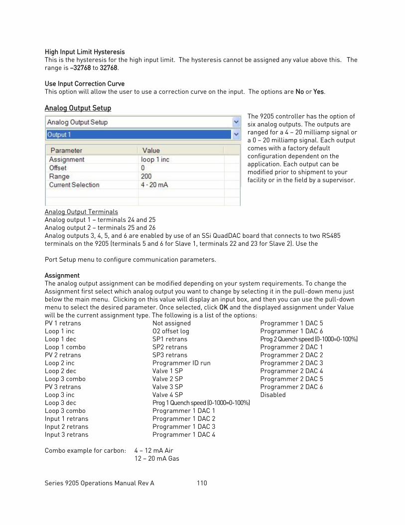
Series 9205 Operations Manual Rev A 110
High Input Limit Hysteresis This is the hysteresis for the high input limit. The hysteresis cannot be assigned any value above this. The range is –32768 to 32768. Use Input Correction Curve This option will allow the user to use a correction curve on the input. The options are No or Yes. Analog Output Setup
The 9205 controller has the option of six analog outputs. The outputs are ranged for a 4 – 20 milliamp signal or a 0 – 20 milliamp signal. Each output comes with a factory default configuration dependent on the application. Each output can be modified prior to shipment to your facility or in the field by a supervisor.
Analog Output Terminals Analog output 1 – terminals 24 and 25 Analog output 2 – terminals 25 and 26 Analog outputs 3, 4, 5, and 6 are enabled by use of an SSi QuadDAC board that connects to two RS485 terminals on the 9205 (terminals 5 and 6 for Slave 1, terminals 22 and 23 for Slave 2). Use the Port Setup menu to configure communication parameters. Assignment The analog output assignment can be modified depending on your system requirements. To change the Assignment first select which analog output you want to change by selecting it in the pull-down menu just below the main menu. Clicking on this value will display an input box, and then you can use the pull-down menu to select the desired parameter. Once selected, click OK and the displayed assignment under Value will be the current assignment type. The following is a list of the options: PV 1 retrans Loop 1 inc Loop 1 dec Loop 1 combo PV 2 retrans Loop 2 inc Loop 2 dec Loop 3 combo PV 3 retrans Loop 3 inc Loop 3 dec Loop 3 combo Input 1 retrans Input 2 retrans Input 3 retrans
Not assigned O2 offset log SP1 retrans SP2 retrans SP3 retrans Programmer ID run Valve 1 SP Valve 2 SP Valve 3 SP Valve 4 SP Prog 1 Quench speed (0-1000=0-100%) Programmer 1 DAC 1 Programmer 1 DAC 2 Programmer 1 DAC 3 Programmer 1 DAC 4
Programmer 1 DAC 5 Programmer 1 DAC 6 Prog 2 Quench speed (0-1000=0-100%) Programmer 2 DAC 1 Programmer 2 DAC 2 Programmer 2 DAC 3 Programmer 2 DAC 4 Programmer 2 DAC 5 Programmer 2 DAC 6 Disabled
Combo example for carbon: 4 – 12 mA Air 12 – 20 mA Gas
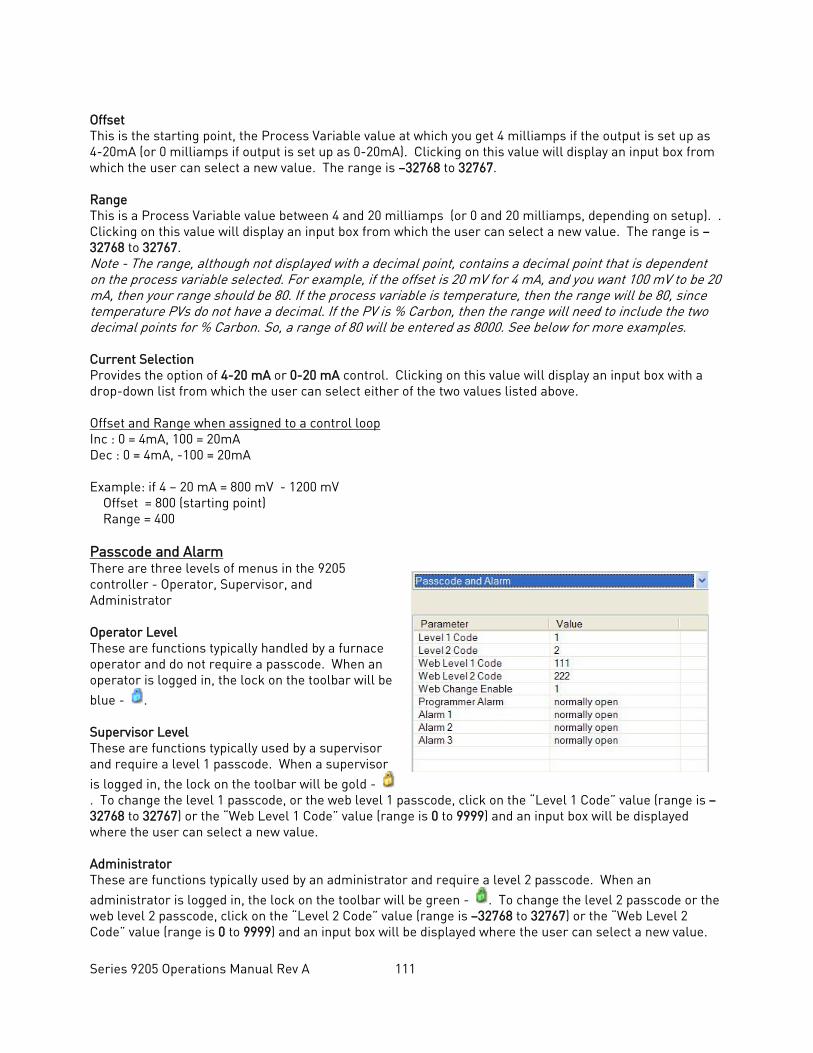
Series 9205 Operations Manual Rev A 111
Offset This is the starting point, the Process Variable value at which you get 4 milliamps if the output is set up as 4-20mA (or 0 milliamps if output is set up as 0-20mA). Clicking on this value will display an input box from which the user can select a new value. The range is –32768 to 32767. Range This is a Process Variable value between 4 and 20 milliamps (or 0 and 20 milliamps, depending on setup). . Clicking on this value will display an input box from which the user can select a new value. The range is –32768 to 32767. Note - The range, although not displayed with a decimal point, contains a decimal point that is dependent on the process variable selected. For example, if the offset is 20 mV for 4 mA, and you want 100 mV to be 20 mA, then your range should be 80. If the process variable is temperature, then the range will be 80, since temperature PVs do not have a decimal. If the PV is % Carbon, then the range will need to include the two decimal points for % Carbon. So, a range of 80 will be entered as 8000. See below for more examples. Current Selection Provides the option of 4-20 mA or 0-20 mA control. Clicking on this value will display an input box with a drop-down list from which the user can select either of the two values listed above. Offset and Range when assigned to a control loop Inc : 0 = 4mA, 100 = 20mA Dec : 0 = 4mA, -100 = 20mA Example: if 4 – 20 mA = 800 mV - 1200 mV Offset = 800 (starting point) Range = 400 Passcode and Alarm There are three levels of menus in the 9205 controller - Operator, Supervisor, and Administrator Operator Level These are functions typically handled by a furnace operator and do not require a passcode. When an operator is logged in, the lock on the toolbar will be blue - . Supervisor Level These are functions typically used by a supervisor and require a level 1 passcode. When a supervisor is logged in, the lock on the toolbar will be gold - . To change the level 1 passcode, or the web level 1 passcode, click on the “Level 1 Code” value (range is –32768 to 32767) or the “Web Level 1 Code” value (range is 0 to 9999) and an input box will be displayed where the user can select a new value. Administrator These are functions typically used by an administrator and require a level 2 passcode. When an administrator is logged in, the lock on the toolbar will be green - . To change the level 2 passcode or the web level 2 passcode, click on the “Level 2 Code” value (range is –32768 to 32767) or the “Web Level 2 Code” value (range is 0 to 9999) and an input box will be displayed where the user can select a new value.

Series 9205 Operations Manual Rev A 112
Web Change Enable This option will determine if changes can be made over the 9205’s web page. Clicking on this value will toggle between a 1 (Yes) and a 0 (No). Programmer Alarm and Alarms 1-3 will allow the user to set up the polarity of the alarms, or determine whether the Normally Closed option or the Normally Open option makes the alarm active.
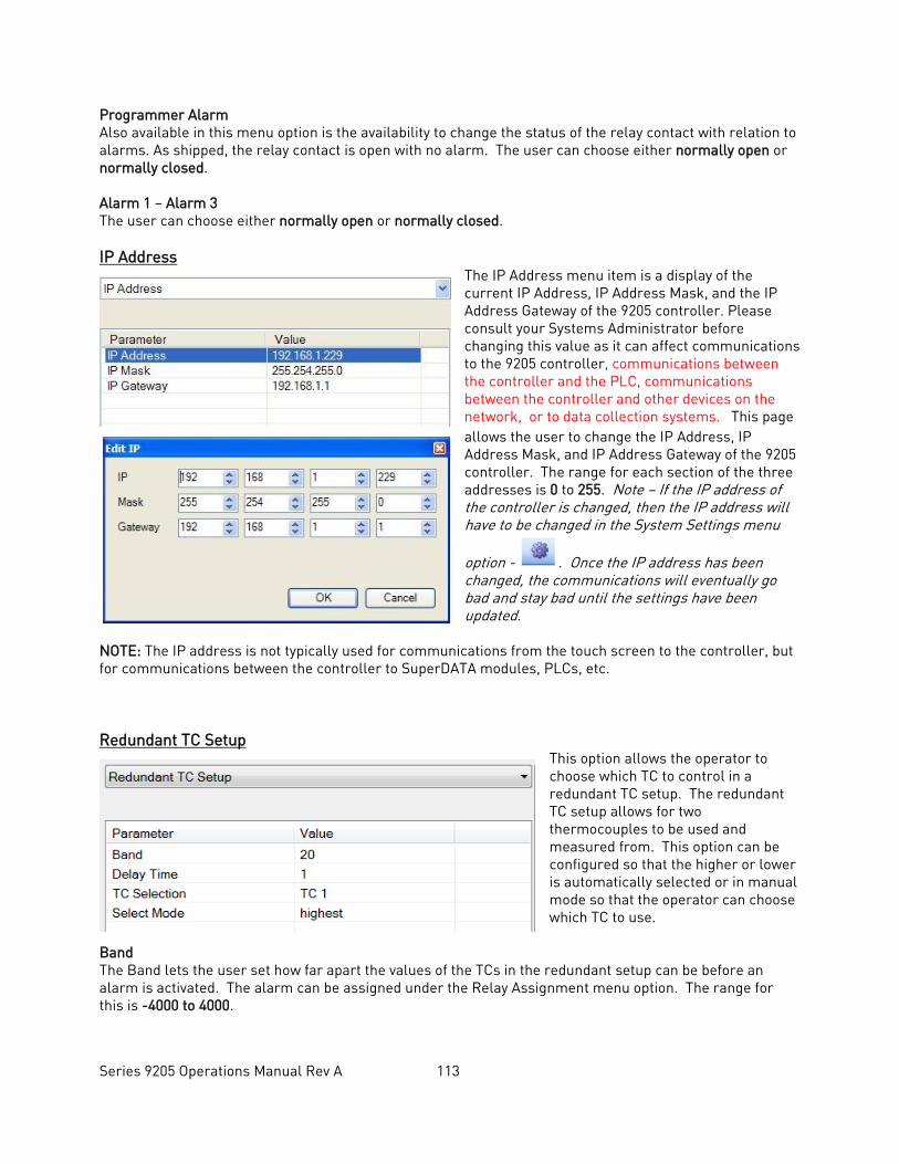
Series 9205 Operations Manual Rev A 113
Programmer Alarm Also available in this menu option is the availability to change the status of the relay contact with relation to alarms. As shipped, the relay contact is open with no alarm. The user can choose either normally open or normally closed. Alarm 1 – Alarm 3 The user can choose either normally open or normally closed. IP Address
The IP Address menu item is a display of the current IP Address, IP Address Mask, and the IP Address Gateway of the 9205 controller. Please consult your Systems Administrator before changing this value as it can affect communications to the 9205 controller, communications between the controller and the PLC, communications between the controller and other devices on the network, or to data collection systems. This page allows the user to change the IP Address, IP Address Mask, and IP Address Gateway of the 9205 controller. The range for each section of the three addresses is 0 to 255. Note – If the IP address of the controller is changed, then the IP address will have to be changed in the System Settings menu
option - . Once the IP address has been changed, the communications will eventually go bad and stay bad until the settings have been updated.
NOTE: The IP address is not typically used for communications from the touch screen to the controller, but for communications between the controller to SuperDATA modules, PLCs, etc. Redundant TC Setup
This option allows the operator to choose which TC to control in a redundant TC setup. The redundant TC setup allows for two thermocouples to be used and measured from. This option can be configured so that the higher or lower is automatically selected or in manual mode so that the operator can choose which TC to use.
Band The Band lets the user set how far apart the values of the TCs in the redundant setup can be before an alarm is activated. The alarm can be assigned under the Relay Assignment menu option. The range for this is -4000 to 4000.
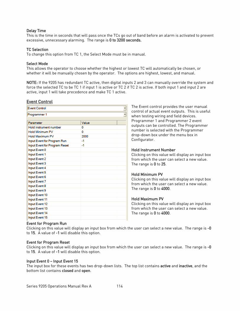
Series 9205 Operations Manual Rev A 114
Delay Time This is the time in seconds that will pass once the TCs go out of band before an alarm is activated to prevent excessive, unnecessary alarming. The range is 0 to 3200 seconds. TC Selection To change this option from TC 1, the Select Mode must be in manual. Select Mode This allows the operator to choose whether the highest or lowest TC will automatically be chosen, or whether it will be manually chosen by the operator. The options are highest, lowest, and manual. NOTE: If the 9205 has redundant TC active, then digital inputs 2 and 3 can manually override the system and force the selected TC to be TC 1 if input 1 is active or TC 2 if TC 2 is active. If both input 1 and input 2 are active, input 1 will take precedence and make TC 1 active. Event Control
The Event control provides the user manual control of actual event outputs. This is useful when testing wiring and field devices. Programmer 1 and Programmer 2 event outputs can be controlled. The Programmer number is selected with the Programmer drop-down box under the menu box in Configurator. Hold Instrument Number Clicking on this value will display an input box from which the user can select a new value. The range is 0 to 25. Hold Minimum PV Clicking on this value will display an input box from which the user can select a new value. The range is 0 to 4000. Hold Maximum PV Clicking on this value will display an input box from which the user can select a new value. The range is 0 to 4000.
Event for Program Run Clicking on this value will display an input box from which the user can select a new value. The range is -0 to 15. A value of -1 will disable this option. Event for Program Reset Clicking on this value will display an input box from which the user can select a new value. The range is -0 to 15. A value of -1 will disable this option. Input Event 0 – Input Event 15 The input box for these events has two drop-down lists. The top list contains active and inactive, and the bottom list contains closed and open.
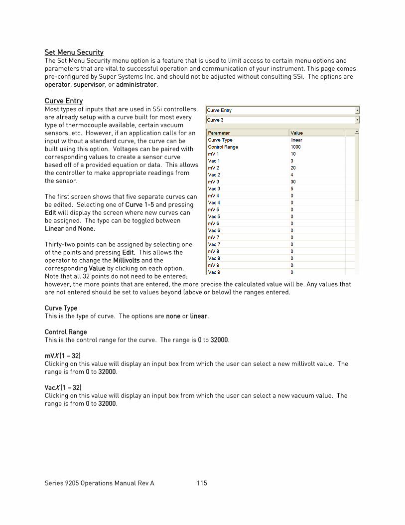
Series 9205 Operations Manual Rev A 115
Set Menu Security The Set Menu Security menu option is a feature that is used to limit access to certain menu options and parameters that are vital to successful operation and communication of your instrument. This page comes pre-configured by Super Systems Inc. and should not be adjusted without consulting SSi. The options are operator, supervisor, or administrator. Curve Entry Most types of inputs that are used in SSi controllers are already setup with a curve built for most every type of thermocouple available, certain vacuum sensors, etc. However, if an application calls for an input without a standard curve, the curve can be built using this option. Voltages can be paired with corresponding values to create a sensor curve based off of a provided equation or data. This allows the controller to make appropriate readings from the sensor. The first screen shows that five separate curves can be edited. Selecting one of Curve 1-5 and pressing Edit will display the screen where new curves can be assigned. The type can be toggled between Linear and None. Thirty-two points can be assigned by selecting one of the points and pressing Edit. This allows the operator to change the Millivolts and the corresponding Value by clicking on each option. Note that all 32 points do not need to be entered; however, the more points that are entered, the more precise the calculated value will be. Any values that are not entered should be set to values beyond (above or below) the ranges entered. Curve Type This is the type of curve. The options are none or linear. Control Range This is the control range for the curve. The range is 0 to 32000. mVX (1 – 32) Clicking on this value will display an input box from which the user can select a new millivolt value. The range is from 0 to 32000. VacX (1 – 32) Clicking on this value will display an input box from which the user can select a new vacuum value. The range is from 0 to 32000.
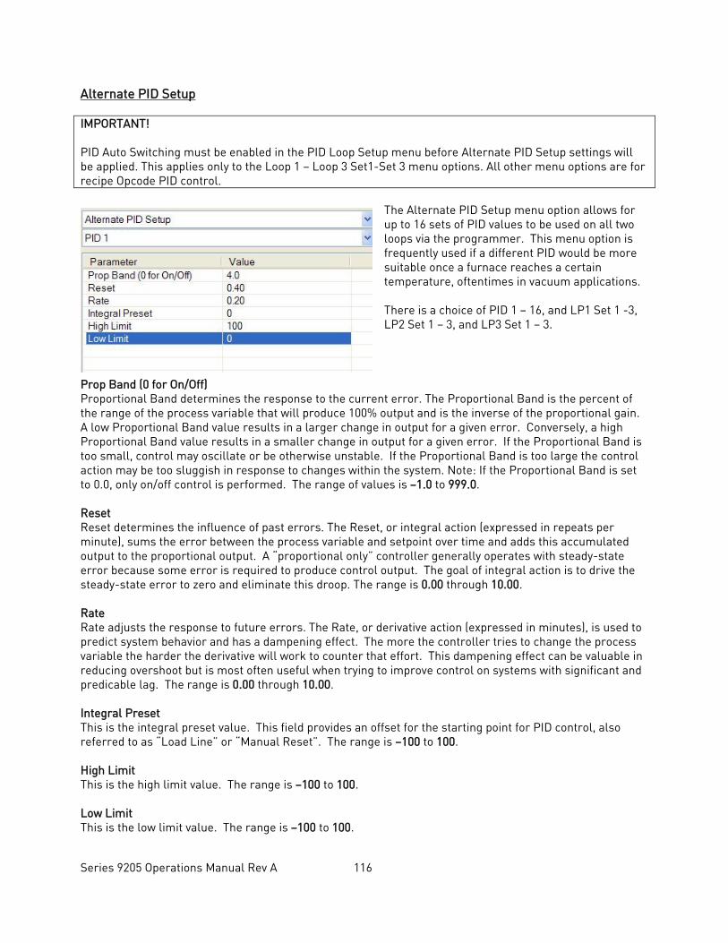
Series 9205 Operations Manual Rev A 116
Alternate PID Setup IMPORTANT! PID Auto Switching must be enabled in the PID Loop Setup menu before Alternate PID Setup settings will be applied. This applies only to the Loop 1 – Loop 3 Set1-Set 3 menu options. All other menu options are for recipe Opcode PID control.
The Alternate PID Setup menu option allows for up to 16 sets of PID values to be used on all two loops via the programmer. This menu option is frequently used if a different PID would be more suitable once a furnace reaches a certain temperature, oftentimes in vacuum applications. There is a choice of PID 1 – 16, and LP1 Set 1 -3, LP2 Set 1 – 3, and LP3 Set 1 – 3.
Prop Band (0 for On/Off) Proportional Band determines the response to the current error. The Proportional Band is the percent of the range of the process variable that will produce 100% output and is the inverse of the proportional gain. A low Proportional Band value results in a larger change in output for a given error. Conversely, a high Proportional Band value results in a smaller change in output for a given error. If the Proportional Band is too small, control may oscillate or be otherwise unstable. If the Proportional Band is too large the control action may be too sluggish in response to changes within the system. Note: If the Proportional Band is set to 0.0, only on/off control is performed. The range of values is –1.0 to 999.0. Reset Reset determines the influence of past errors. The Reset, or integral action (expressed in repeats per minute), sums the error between the process variable and setpoint over time and adds this accumulated output to the proportional output. A “proportional only” controller generally operates with steady-state error because some error is required to produce control output. The goal of integral action is to drive the steady-state error to zero and eliminate this droop. The range is 0.00 through 10.00. Rate Rate adjusts the response to future errors. The Rate, or derivative action (expressed in minutes), is used to predict system behavior and has a dampening effect. The more the controller tries to change the process variable the harder the derivative will work to counter that effort. This dampening effect can be valuable in reducing overshoot but is most often useful when trying to improve control on systems with significant and predicable lag. The range is 0.00 through 10.00. Integral Preset This is the integral preset value. This field provides an offset for the starting point for PID control, also referred to as “Load Line” or “Manual Reset”. The range is –100 to 100. High Limit This is the high limit value. The range is –100 to 100. Low Limit This is the low limit value. The range is –100 to 100.
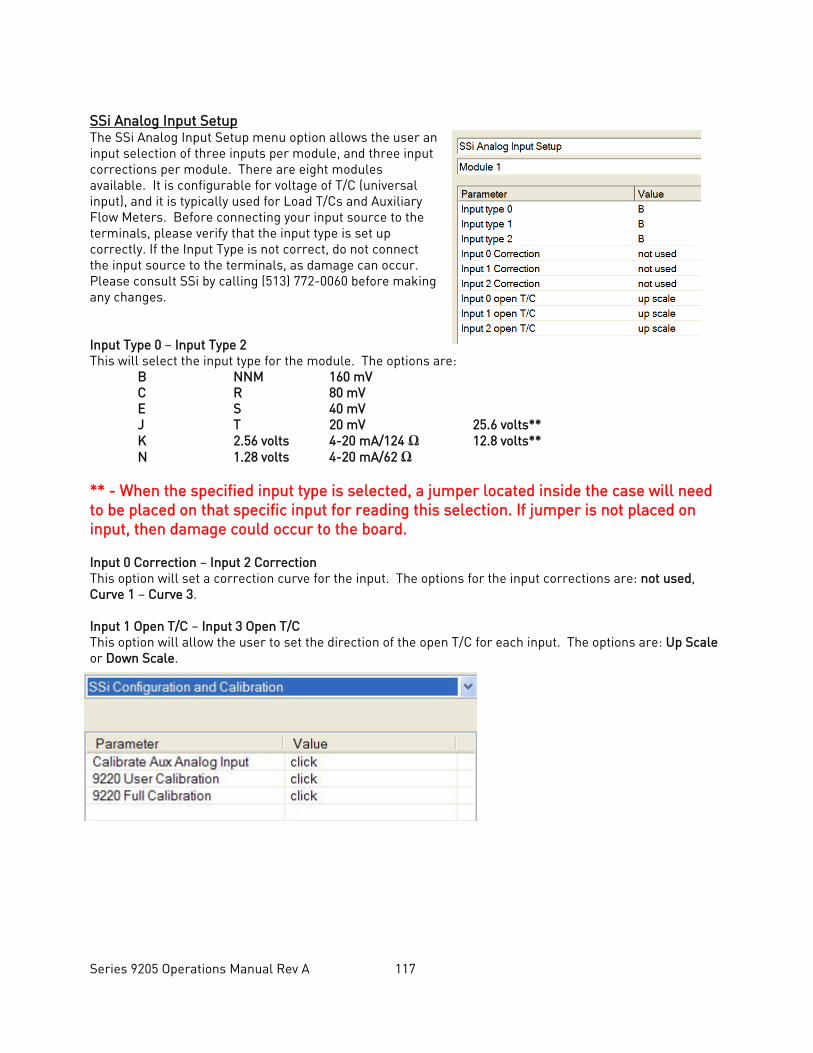
Series 9205 Operations Manual Rev A 117
SSi Analog Input Setup The SSi Analog Input Setup menu option allows the user an input selection of three inputs per module, and three input corrections per module. There are eight modules available. It is configurable for voltage of T/C (universal input), and it is typically used for Load T/Cs and Auxiliary Flow Meters. Before connecting your input source to the terminals, please verify that the input type is set up correctly. If the Input Type is not correct, do not connect the input source to the terminals, as damage can occur. Please consult SSi by calling (513) 772-0060 before making any changes. Input Type 0 – Input Type 2 This will select the input type for the module. The options are: B NNM 160 mV C R 80 mV E S 40 mV J T 20 mV 25.6 volts** K 2.56 volts 4-20 mA/124 Ω 12.8 volts** N 1.28 volts 4-20 mA/62 Ω ** - When the specified input type is selected, a jumper located inside the case will need to be placed on that specific input for reading this selection. If jumper is not placed on input, then damage could occur to the board. Input 0 Correction – Input 2 Correction This option will set a correction curve for the input. The options for the input corrections are: not used, Curve 1 – Curve 3. Input 1 Open T/C – Input 3 Open T/C This option will allow the user to set the direction of the open T/C for each input. The options are: Up Scale or Down Scale.
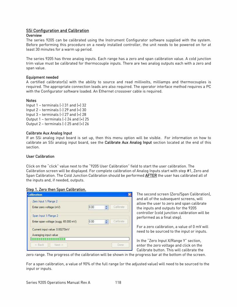
Series 9205 Operations Manual Rev A 118
SSi Configuration and Calibration Overview The series 9205 can be calibrated using the Instrument Configurator software supplied with the system. Before performing this procedure on a newly installed controller, the unit needs to be powered on for at least 30 minutes for a warm up period. The series 9205 has three analog inputs. Each range has a zero and span calibration value. A cold junction trim value must be calibrated for thermocouple inputs. There are two analog outputs each with a zero and span value. Equipment needed A certified calibrator(s) with the ability to source and read millivolts, milliamps and thermocouples is required. The appropriate connection leads are also required. The operator interface method requires a PC with the Configurator software loaded. An Ethernet crossover cable is required. Notes Input 1 – terminals (-) 31 and (+) 32 Input 2 – terminals (-) 29 and (+) 30 Input 3 – terminals (-) 27 and (+) 28 Output 1 – terminals (-) 24 and (+) 25 Output 2 – terminals (-) 25 and (+) 26 Calibrate Aux Analog Input If an SSi analog input board is set up, then this menu option will be visible. For information on how to calibrate an SSi analog input board, see the Calibrate Aux Analog Input section located at the end of this section. User Calibration Click on the “click” value next to the “9205 User Calibration” field to start the user calibration. The Calibration screen will be displayed. For complete calibration of Analog Inputs start with step #1, Zero and Span Calibration. The Cold Junction Calibration should be performed AFTER the user has calibrated all of the inputs and, if needed, outputs. Step 1. Zero then Span Calibration.
The second screen (Zero/Span Calibration), and all of the subsequent screens, will allow the user to zero and span calibrate the inputs and outputs for the 9205 controller (cold junction calibration will be performed as a final step). For a zero calibration, a value of 0 mV will need to be sourced to the input or inputs. In the “Zero Input X/Range Y” section, enter the zero voltage and click on the Calibrate button. This will calibrate the
zero range. The progress of the calibration will be shown in the progress bar at the bottom of the screen. For a span calibration, a value of 90% of the full range (or the adjusted value) will need to be sourced to the input or inputs.
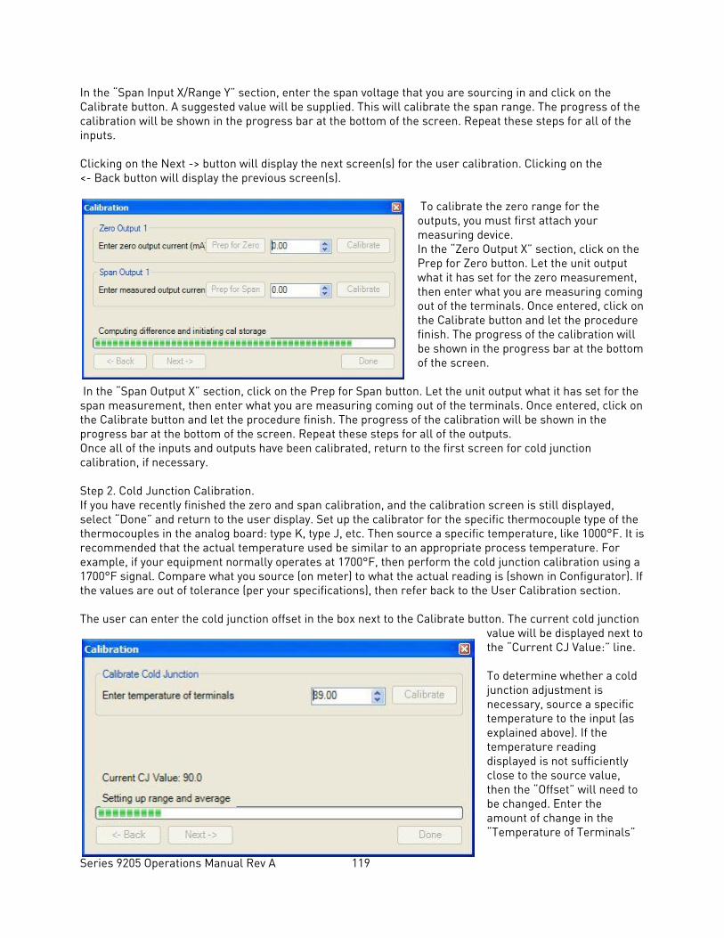
Series 9205 Operations Manual Rev A 119
In the “Span Input X/Range Y” section, enter the span voltage that you are sourcing in and click on the Calibrate button. A suggested value will be supplied. This will calibrate the span range. The progress of the calibration will be shown in the progress bar at the bottom of the screen. Repeat these steps for all of the inputs. Clicking on the Next -> button will display the next screen(s) for the user calibration. Clicking on the <- Back button will display the previous screen(s).
To calibrate the zero range for the outputs, you must first attach your measuring device. In the “Zero Output X” section, click on the Prep for Zero button. Let the unit output what it has set for the zero measurement, then enter what you are measuring coming out of the terminals. Once entered, click on the Calibrate button and let the procedure finish. The progress of the calibration will be shown in the progress bar at the bottom of the screen.
In the “Span Output X” section, click on the Prep for Span button. Let the unit output what it has set for the span measurement, then enter what you are measuring coming out of the terminals. Once entered, click on the Calibrate button and let the procedure finish. The progress of the calibration will be shown in the progress bar at the bottom of the screen. Repeat these steps for all of the outputs. Once all of the inputs and outputs have been calibrated, return to the first screen for cold junction calibration, if necessary. Step 2. Cold Junction Calibration. If you have recently finished the zero and span calibration, and the calibration screen is still displayed, select “Done” and return to the user display. Set up the calibrator for the specific thermocouple type of the thermocouples in the analog board: type K, type J, etc. Then source a specific temperature, like 1000°F. It is recommended that the actual temperature used be similar to an appropriate process temperature. For example, if your equipment normally operates at 1700°F, then perform the cold junction calibration using a 1700°F signal. Compare what you source (on meter) to what the actual reading is (shown in Configurator). If the values are out of tolerance (per your specifications), then refer back to the User Calibration section. The user can enter the cold junction offset in the box next to the Calibrate button. The current cold junction
value will be displayed next to the “Current CJ Value:” line. To determine whether a cold junction adjustment is necessary, source a specific temperature to the input (as explained above). If the temperature reading displayed is not sufficiently close to the source value, then the “Offset” will need to be changed. Enter the amount of change in the “Temperature of Terminals”
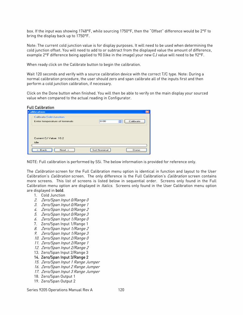
Series 9205 Operations Manual Rev A 120
box. If the input was showing 1748°F, while sourcing 1750°F, then the “Offset” difference would be 2°F to bring the display back up to 1750°F. Note: The current cold junction value is for display purposes. It will need to be used when determining the cold junction offset. You will need to add to or subtract from the displayed value the amount of difference, example 2°F difference being applied to 90 (like in the image) your new CJ value will need to be 92°F. When ready click on the Calibrate button to begin the calibration. Wait 120 seconds and verify with a source calibration device with the correct T/C type. Note: During a normal calibration procedure, the user should zero and span calibrate all of the inputs first and then perform a cold junction calibration, if necessary. Click on the Done button when finished. You will then be able to verify on the main display your sourced value when compared to the actual reading in Configurator. Full Calibration
NOTE: Full calibration is performed by SSi. The below information is provided for reference only. The Calibration screen for the Full Calibration menu option is identical in function and layout to the User Calibration’s Calibration screen. The only difference is the Full Calibration’s Calibration screen contains more screens. This list of screens is listed below in sequential order. Screens only found in the Full Calibration menu option are displayed in Italics. Screens only found in the User Calibration menu option are displayed in bold.
1. Cold Junction 2. Zero/Span Input 0/Range 0 3. Zero/Span Input 0/Range 1 4. Zero/Span Input 0/Range 2 5. Zero/Span Input 0/Range 3 6. Zero/Span Input 1/Range 0 7. Zero/Span Input 1/Range 1 8. Zero/Span Input 1/Range 2 9. Zero/Span Input 1/Range 3 10. Zero/Span Input 2/Range 0 11. Zero/Span Input 2/Range 1 12. Zero/Span Input 2/Range 2 13. Zero/Span Input 2/Range 3 14. Zero/Span Input 3/Range 2 15. Zero/Span Input 1 Range Jumper 16. Zero/Span Input 2 Range Jumper 17. Zero/Span Input 3 Range Jumper 18. Zero/Span Output 1 19. Zero/Span Output 2
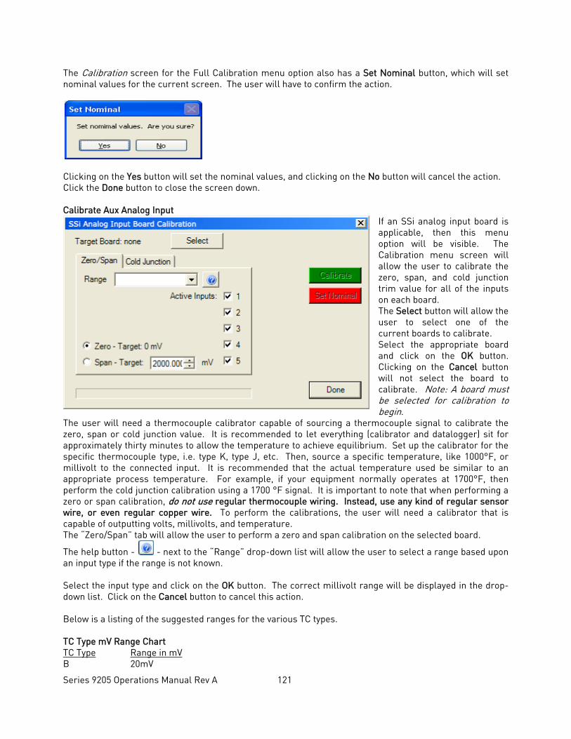
Series 9205 Operations Manual Rev A 121
The Calibration screen for the Full Calibration menu option also has a Set Nominal button, which will set nominal values for the current screen. The user will have to confirm the action.
Clicking on the Yes button will set the nominal values, and clicking on the No button will cancel the action. Click the Done button to close the screen down. Calibrate Aux Analog Input
If an SSi analog input board is applicable, then this menu option will be visible. The Calibration menu screen will allow the user to calibrate the zero, span, and cold junction trim value for all of the inputs on each board. The Select button will allow the user to select one of the current boards to calibrate. Select the appropriate board and click on the OK button. Clicking on the Cancel button will not select the board to calibrate. Note: A board must be selected for calibration to begin.
The user will need a thermocouple calibrator capable of sourcing a thermocouple signal to calibrate the zero, span or cold junction value. It is recommended to let everything (calibrator and datalogger) sit for approximately thirty minutes to allow the temperature to achieve equilibrium. Set up the calibrator for the specific thermocouple type, i.e. type K, type J, etc. Then, source a specific temperature, like 1000°F, or millivolt to the connected input. It is recommended that the actual temperature used be similar to an appropriate process temperature. For example, if your equipment normally operates at 1700°F, then perform the cold junction calibration using a 1700 °F signal. It is important to note that when performing a zero or span calibration, do not use regular thermocouple wiring. Instead, use any kind of regular sensor wire, or even regular copper wire. To perform the calibrations, the user will need a calibrator that is capable of outputting volts, millivolts, and temperature. The “Zero/Span” tab will allow the user to perform a zero and span calibration on the selected board.
The help button - - next to the “Range” drop-down list will allow the user to select a range based upon an input type if the range is not known. Select the input type and click on the OK button. The correct millivolt range will be displayed in the drop-down list. Click on the Cancel button to cancel this action. Below is a listing of the suggested ranges for the various TC types. TC Type mV Range Chart TC Type Range in mV B 20mV
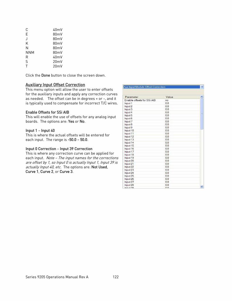
Series 9205 Operations Manual Rev A 122
C 40mV E 80mV J 80mV K 80mV N 80mV NNM 80mV R 40mV S 20mV T 20mV Click the Done button to close the screen down. Auxiliary Input Offset Correction This menu option will allow the user to enter offsets for the auxiliary inputs and apply any correction curves as needed. The offset can be in degrees + or -, and it is typically used to compensate for incorrect T/C wires. Enable Offsets for SSi AIB This will enable the use of offsets for any analog input boards. The options are: Yes or No. Input 1 – Input 40 This is where the actual offsets will be entered for each input. The range is -50.0 – 50.0. Input 0 Correction – Input 39 Correction This is where any correction curve can be applied for each input. Note – The input names for the corrections are offset by 1, so Input 0 is actually Input 1, Input 39 is actually Input 40, etc. The options are: Not Used, Curve 1, Curve 2, or Curve 3.
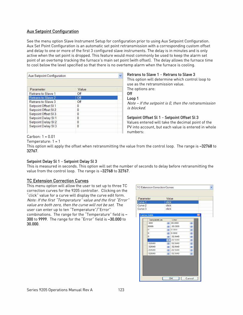
Series 9205 Operations Manual Rev A 123
Aux Setpoint Configuration See the menu option Slave Instrument Setup for configuration prior to using Aux Setpoint Configuration. Aux Set Point Configuration is an automatic set point retransmission with a corresponding custom offset and delay to one or more of the first 3 configured slave instruments. The delay is in minutes and is only active when the set point is dropped. This feature would most commonly be used to keep the alarm set point of an overtemp tracking the furnace's main set point (with offset). The delay allows the furnace time to cool below the level specified so that there is no overtemp alarm when the furnace is cooling.
Retrans to Slave 1 – Retrans to Slave 3 This option will determine which control loop to use as the retransmission value. The options are: Off Loop 1 Note – If the setpoint is 0, then the retransmission is blocked. Setpoint Offset Sl 1 – Setpoint Offset Sl 3 Values entered will take the decimal point of the PV into account, but each value is entered in whole numbers:
Carbon: 1 = 0.01 Temperature: 1 = 1 This option will apply the offset when retransmitting the value from the control loop. The range is –32768 to 32767. Setpoint Delay Sl 1 – Setpoint Delay Sl 3 This is measured in seconds. This option will set the number of seconds to delay before retransmitting the value from the control loop. The range is –32768 to 32767. TC Extension Correction Curves This menu option will allow the user to set up to three TC correction curves for the 9205 controller. Clicking on the “click” value for a curve will display the curve edit form. Note: If the first “Temperature” value and the first “Error” value are both zero, then the curve will not be set. The user can enter up to ten “Temperature”/“Error” combinations. The range for the “Temperature” field is –300 to 9999. The range for the “Error” field is –30.000 to 30.000.
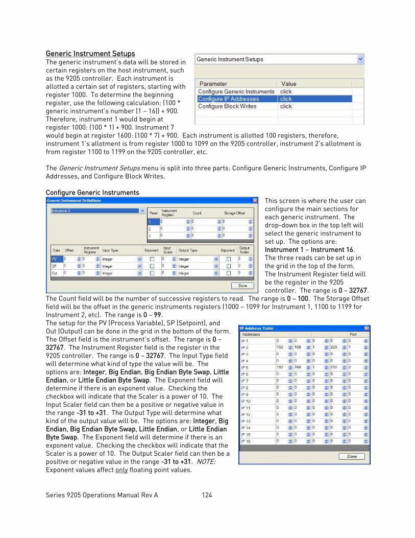
Series 9205 Operations Manual Rev A 124
Generic Instrument Setups The generic instrument’s data will be stored in certain registers on the host instrument, such as the 9205 controller. Each instrument is allotted a certain set of registers, starting with register 1000. To determine the beginning register, use the following calculation: (100 * generic instrument’s number (1 – 16)) + 900. Therefore, instrument 1 would begin at register 1000: (100 * 1) + 900. Instrument 7 would begin at register 1600: (100 * 7) + 900. Each instrument is allotted 100 registers, therefore, instrument 1’s allotment is from register 1000 to 1099 on the 9205 controller, instrument 2’s allotment is from register 1100 to 1199 on the 9205 controller, etc. The Generic Instrument Setups menu is split into three parts: Configure Generic Instruments, Configure IP Addresses, and Configure Block Writes. Configure Generic Instruments
This screen is where the user can configure the main sections for each generic instrument. The drop-down box in the top left will select the generic instrument to set up. The options are: Instrument 1 – Instrument 16. The three reads can be set up in the grid in the top of the form. The Instrument Register field will be the register in the 9205 controller. The range is 0 – 32767.
The Count field will be the number of successive registers to read. The range is 0 – 100. The Storage Offset field will be the offset in the generic instruments registers (1000 – 1099 for Instrument 1, 1100 to 1199 for Instrument 2, etc). The range is 0 – 99. The setup for the PV (Process Variable), SP (Setpoint), and Out (Output) can be done in the grid in the bottom of the form. The Offset field is the instrument’s offset. The range is 0 – 32767. The Instrument Register field is the register in the 9205 controller. The range is 0 – 32767. The Input Type field will determine what kind of type the value will be. The options are: Integer, Big Endian, Big Endian Byte Swap, Little Endian, or Little Endian Byte Swap. The Exponent field will determine if there is an exponent value. Checking the checkbox will indicate that the Scaler is a power of 10. The Input Scaler field can then be a positive or negative value in the range -31 to +31. The Output Type will determine what kind of the output value will be. The options are: Integer, Big Endian, Big Endian Byte Swap, Little Endian, or Little Endian Byte Swap. The Exponent field will determine if there is an exponent value. Checking the checkbox will indicate that the Scaler is a power of 10. The Output Scaler field can then be a positive or negative value in the range -31 to +31. NOTE: Exponent values affect only floating point values.
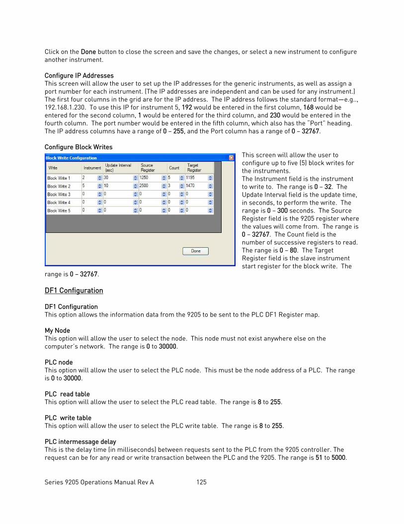
Series 9205 Operations Manual Rev A 125
Click on the Done button to close the screen and save the changes, or select a new instrument to configure another instrument. Configure IP Addresses This screen will allow the user to set up the IP addresses for the generic instruments, as well as assign a port number for each instrument. (The IP addresses are independent and can be used for any instrument.) The first four columns in the grid are for the IP address. The IP address follows the standard format—e.g.., 192.168.1.230. To use this IP for instrument 5, 192 would be entered in the first column, 168 would be entered for the second column, 1 would be entered for the third column, and 230 would be entered in the fourth column. The port number would be entered in the fifth column, which also has the “Port” heading. The IP address columns have a range of 0 – 255, and the Port column has a range of 0 – 32767. Configure Block Writes
This screen will allow the user to configure up to five (5) block writes for the instruments. The Instrument field is the instrument to write to. The range is 0 – 32. The Update Interval field is the update time, in seconds, to perform the write. The range is 0 – 300 seconds. The Source Register field is the 9205 register where the values will come from. The range is 0 – 32767. The Count field is the number of successive registers to read. The range is 0 – 80. The Target Register field is the slave instrument start register for the block write. The
range is 0 – 32767. DF1 Configuration DF1 Configuration This option allows the information data from the 9205 to be sent to the PLC DF1 Register map. My Node This option will allow the user to select the node. This node must not exist anywhere else on the computer’s network. The range is 0 to 30000. PLC node This option will allow the user to select the PLC node. This must be the node address of a PLC. The range is 0 to 30000. PLC read table This option will allow the user to select the PLC read table. The range is 8 to 255. PLC write table This option will allow the user to select the PLC write table. The range is 8 to 255. PLC intermessage delay This is the delay time (in milliseconds) between requests sent to the PLC from the 9205 controller. The request can be for any read or write transaction between the PLC and the 9205. The range is 51 to 5000.
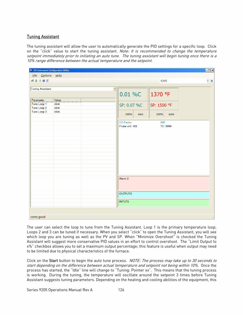
Series 9205 Operations Manual Rev A 126
Tuning Assistant The tuning assistant will allow the user to automatically generate the PID settings for a specific loop. Click on the “click” value to start the tuning assistant. Note: It is recommended to change the temperature setpoint immediately prior to initiating an auto tune. The tuning assistant will begin tuning once there is a 10% range difference between the actual temperature and the setpoint.
The user can select the loop to tune from the Tuning Assistant. Loop 1 is the primary temperature loop; Loops 2 and 3 can be tuned if necessary. When you select “click” to open the Tuning Assistant, you will see which loop you are tuning as well as the PV and SP. When "Minimize Overshoot" is checked the Tuning Assistant will suggest more conservative PID values in an effort to control overshoot. The “Limit Output to x%” checkbox allows you to set a maximum output percentage; this feature is useful when output may need to be limited due to physical characteristics of the furnace. Click on the Start button to begin the auto tune process. NOTE: The process may take up to 30 seconds to start depending on the difference between actual temperature and setpoint not being within 10%. Once the process has started, the “Idle” line will change to “Tuning: Pointer xx”. This means that the tuning process is working. During the tuning, the temperature will oscillate around the setpoint 3 times before Tuning Assistant suggests tuning parameters. Depending on the heating and cooling abilities of the equipment, this
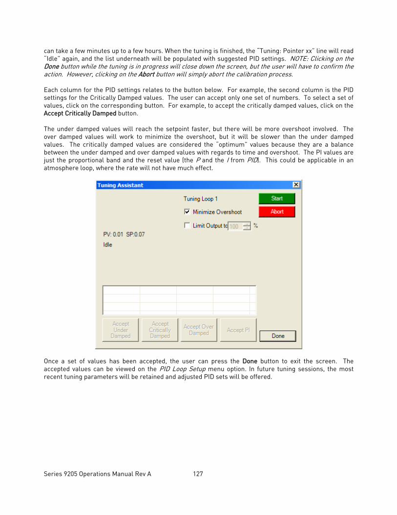
Series 9205 Operations Manual Rev A 127
can take a few minutes up to a few hours. When the tuning is finished, the “Tuning: Pointer xx” line will read “Idle” again, and the list underneath will be populated with suggested PID settings. NOTE: Clicking on the Done button while the tuning is in progress will close down the screen, but the user will have to confirm the action. However, clicking on the Abort button will simply abort the calibration process. Each column for the PID settings relates to the button below. For example, the second column is the PID settings for the Critically Damped values. The user can accept only one set of numbers. To select a set of values, click on the corresponding button. For example, to accept the critically damped values, click on the Accept Critically Damped button. The under damped values will reach the setpoint faster, but there will be more overshoot involved. The over damped values will work to minimize the overshoot, but it will be slower than the under damped values. The critically damped values are considered the “optimum” values because they are a balance between the under damped and over damped values with regards to time and overshoot. The PI values are just the proportional band and the reset value (the P and the I from PID). This could be applicable in an atmosphere loop, where the rate will not have much effect.
Once a set of values has been accepted, the user can press the Done button to exit the screen. The accepted values can be viewed on the PID Loop Setup menu option. In future tuning sessions, the most recent tuning parameters will be retained and adjusted PID sets will be offered.
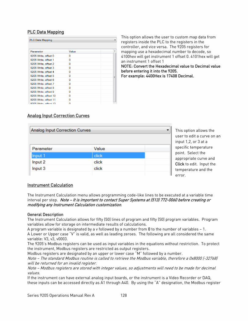
Series 9205 Operations Manual Rev A 128
PLC Data Mapping This option allows the user to custom map data from registers inside the PLC to the registers in the controller, and vice versa. The 9205 registers for mapping use a hexadecimal number to decode, so 4100hex will get instrument 1 offset 0. 4101hex will get an instrument 1 offset 1 NOTE: Convert the Hexadecimal value to Decimal value before entering it into the 9205. For example: 4400Hex is 17408 Decimal.
Analog Input Correction Curves
This option allows the user to edit a curve on an input 1,2, or 3 at a specific temperature point. Select the appropriate curve and Click to edit. Input the temperature and the error.
Instrument Calculation The Instrument Calculation menu allows programming code-like lines to be executed at a variable time interval per step. Note – It is important to contact Super Systems at (513) 772-0060 before creating or modifying any Instrument Calculation customization. General Description The Instrument Calculation allows for fifty (50) lines of program and fifty (50) program variables. Program variables allow for storage on intermediate results of calculations. A program variable is designated by a v followed by a number from 0 to the number of variables – 1. A Lower or Upper case “V” is valid, as well as leading zeroes. The following are all considered the same variable: V3, v3, v0003. The 9205’s Modbus registers can be used as input variables in the equations without restriction. To protect the instrument, Modbus registers are restricted as output registers. Modbus registers are designated by an upper or lower case “M” followed by a number. Note – The standard Modbus routine is called to retrieve the Modbus variable, therefore a 0x8000 (-32768) will be returned for an invalid register. Note – Modbus registers are stored with integer values, so adjustments will need to be made for decimal values. If the instrument can have external analog input boards, or the instrument is a Video Recorder or DAQ, these inputs can be accessed directly as A1 through A40. By using the “A” designation, the Modbus register
Series 9205 Operations Manual Rev A 129
number is not needed and the variable is scaled to the correct value (decimals included) based on the input type specified. In a Video Recorder, the slave instrument data slots can be defined as variables D1 through D32. D31 and D32 are extra slots and have no restrictions as output variables. D1 through D30 are shared with the first ten (10) slave instruments in groups of three (3) – PV, SP, PO – and caution should be used when assigning as outputs. A line in the program of the instrument calculation must start with a variable or a keyword. Variables must be followed by an equal sign (=) and then an expression. The expression can be a simple assignment (V1 = 3) or a variable operation variable as described below (V1 = M225 * 0.1). Keywords MUST be entered in capital letters only. The list of valid keywords is: IF, ELSE, ENDIF, QUE, RLY, and END. “IF” must be followed by an expression which is a variable, relationship operator, then variable. The list of valid relationship operators is: > (Greater Than), < (Less Than). = (Equals), >= (Greater Than or Equal To), <= (Less Than or Equal To), != (Not Equal To), and == (Equal To). Note – The “=” and “==” relationship operators are identical. The list of valid bitwise operators is: & (AND), | (OR), ^ (XOR), << (Left Shift), and >> (Right Shift). The result of the “IF” relationship test determines if the lines following the “IF” statement will be executed or not. The “ELSE” and “ENDIF” must be on a line by themselves. “ELSE” will toggle the program based on the result of the “IF” test. “ENDIF” will close out the “IF”. Example: IF V1 >= 30 V3 = V2 * 1.5 ELSE V3 = 5 ENDIF In this example, if the value in V1 is greater than or equal to 30, then the value of V3 will be the value of V2 multiplied by 1.5. If the value in V1 is less than 30, the value of V3 will be 5. EVERY “IF” must have a closing “ENDIF”. However, the “ELSE” is optional. The “QUE” is used to send data to a slave instrument and must have three (3) variables separated by spaces. The first is the slave instrument number, the second is the register number, and the third is the data to send. Example: QUE 3 1129 V1 This example will send the value of V1 to register 1129 on instrument 3. The “RLY” is used to control a relay if the relay assignment is 999. The “RLY” must be followed by a variable which is the relay number (1 – 8) and a relationship expression. Example: RLY 5 M554 < 2 This example would turn Relay 5 ON if the communication status for instrument 5 was bad. The “END” keyword will stop the lines from running, and start over from line 1. There are a few functions that are available as well. The list of valid functions is: FSIN (Sine), FCOS (Cosine), FEXP (Exponent), FLOG (Logarithm), FLN (Natural Logarithm), FSQRT (Square Root), FABS (Absolute Value), and FPOW (Power). The Sine and Cosine functions need to have the parameter in radians. A function must be in all caps and begin with an “F” and have a pair of parenthesis. An undefined function returns the value of the expression in the parenthesis. Note – A pair of parenthesis by themselves is considered an undefined function. The instrument calculation has limited parsing ability. This is kept to variables, operation, variable – i.e. V1 = 12.25 * V2. Another example is M128 = V1/100. A negative sign (-) in front of the number is considered part of the number – i.e. V1 = -2.55 + V2. A variable to the parser is one of the following: a program variable (Vxx), a Modbus register (Mxxx), a number, or a function. Example: V1 = (V2 * 1.35) + (V3 * V4)
Series 9205 Operations Manual Rev A 130
This example will multiple V2 by 1.35 and multiply V3 and V4 together, and add those two results and store that value in V1. The maximum length of a program line is thirty-one (31) characters. The following are the valid mathematical operators: + (Addition), - (Subtraction), * (Multiplication), / (Division), and % (Modulo Divide – integer only). The difference between Division and Modulo Division is that Modulo will always return an integer value. Example: 11 / 4 = 2.75 11 % 4 = 2 (The .75 will not be returned) Calculation Time In MS (0 to Disable) This is the calculation time for the calculations. This will specify the delay between executing a line. Each line has the same delay between them, even if they are blank. A value of zero (0) will keep the calculations from being performed. The range is 0 – 10000. Configure Instrument Calculations This option will display the screen where the calculations can be entered. To edit a line, click on the Edit button. This will bring up the keyboard, which will allow the user to change the text for the calculation. If Edit is clicked on a blank line, a new calculation can be entered. To Insert a blank line in between lines, select the line BELOW where the inserted line is going to go and click on the Insert button. To delete a line, highlight the line and click on the Delete button. To erase a line, highlight the line and click on the Clear button.
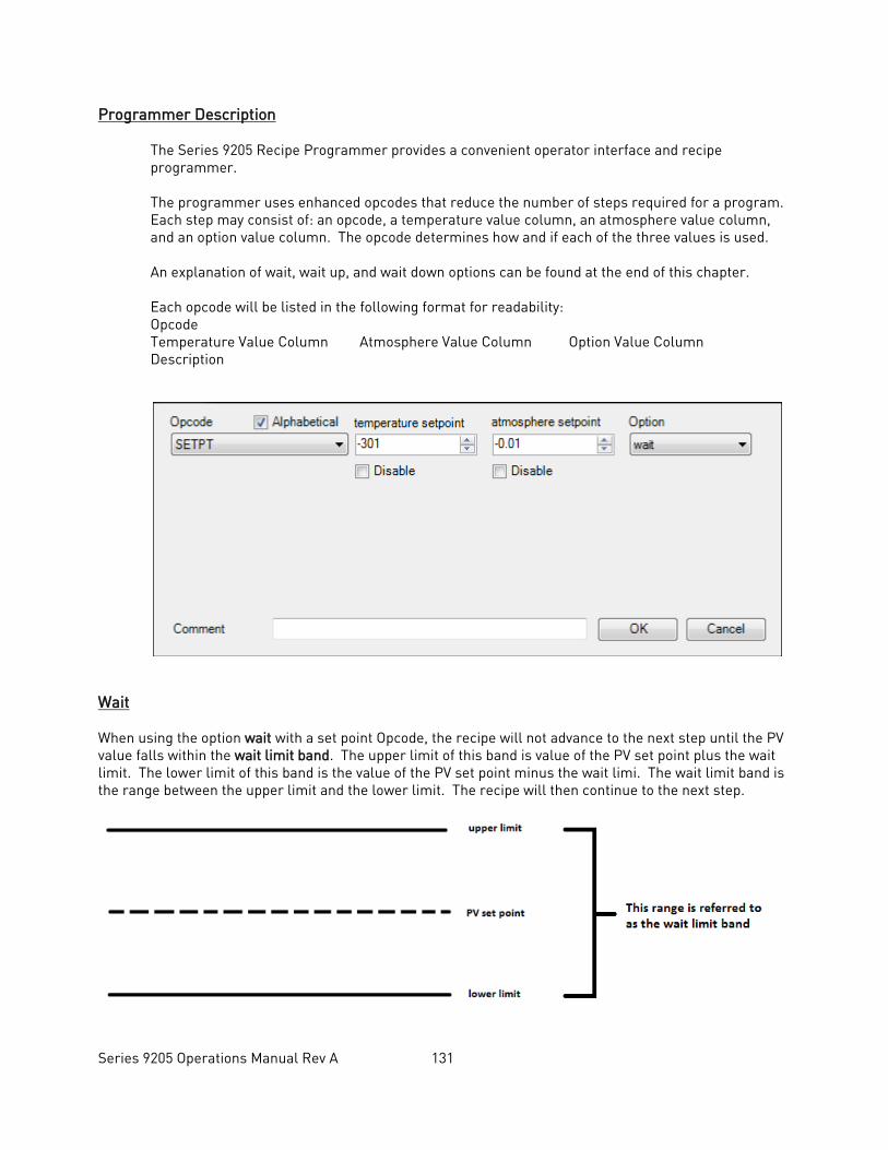
Series 9205 Operations Manual Rev A 131
Programmer Description
The Series 9205 Recipe Programmer provides a convenient operator interface and recipe programmer. The programmer uses enhanced opcodes that reduce the number of steps required for a program. Each step may consist of: an opcode, a temperature value column, an atmosphere value column, and an option value column. The opcode determines how and if each of the three values is used. An explanation of wait, wait up, and wait down options can be found at the end of this chapter. Each opcode will be listed in the following format for readability: Opcode Temperature Value Column Atmosphere Value Column Option Value Column Description
Wait When using the option wait with a set point Opcode, the recipe will not advance to the next step until the PV value falls within the wait limit band. The upper limit of this band is value of the PV set point plus the wait limit. The lower limit of this band is the value of the PV set point minus the wait limi. The wait limit band is the range between the upper limit and the lower limit. The recipe will then continue to the next step.
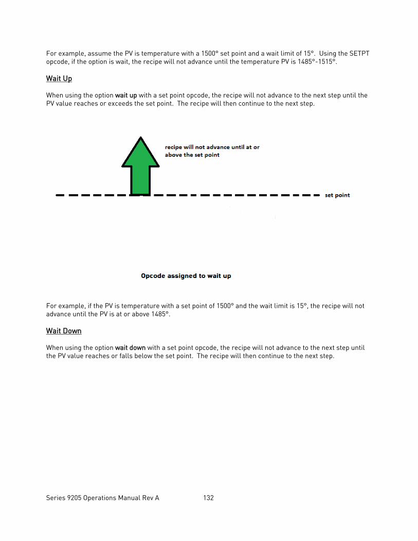
Series 9205 Operations Manual Rev A 132
For example, assume the PV is temperature with a 1500° set point and a wait limit of 15°. Using the SETPT opcode, if the option is wait, the recipe will not advance until the temperature PV is 1485°-1515°. Wait Up When using the option wait up with a set point opcode, the recipe will not advance to the next step until the PV value reaches or exceeds the set point. The recipe will then continue to the next step.
For example, if the PV is temperature with a set point of 1500° and the wait limit is 15°, the recipe will not advance until the PV is at or above 1485°. Wait Down When using the option wait down with a set point opcode, the recipe will not advance to the next step until the PV value reaches or falls below the set point. The recipe will then continue to the next step.
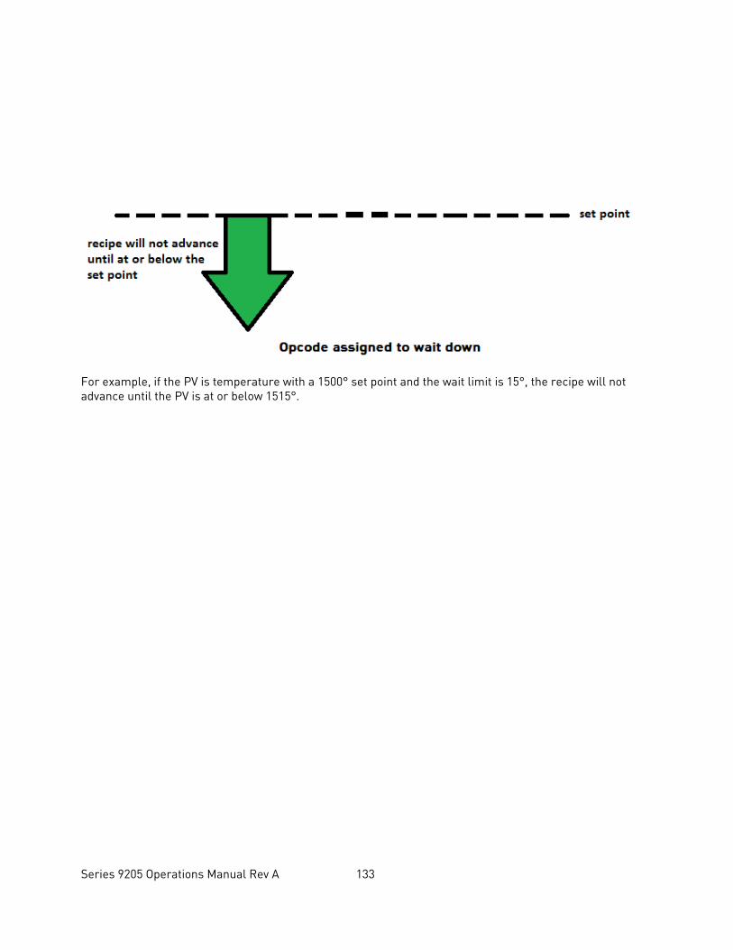
Series 9205 Operations Manual Rev A 133
For example, if the PV is temperature with a 1500° set point and the wait limit is 15°, the recipe will not advance until the PV is at or below 1515°.
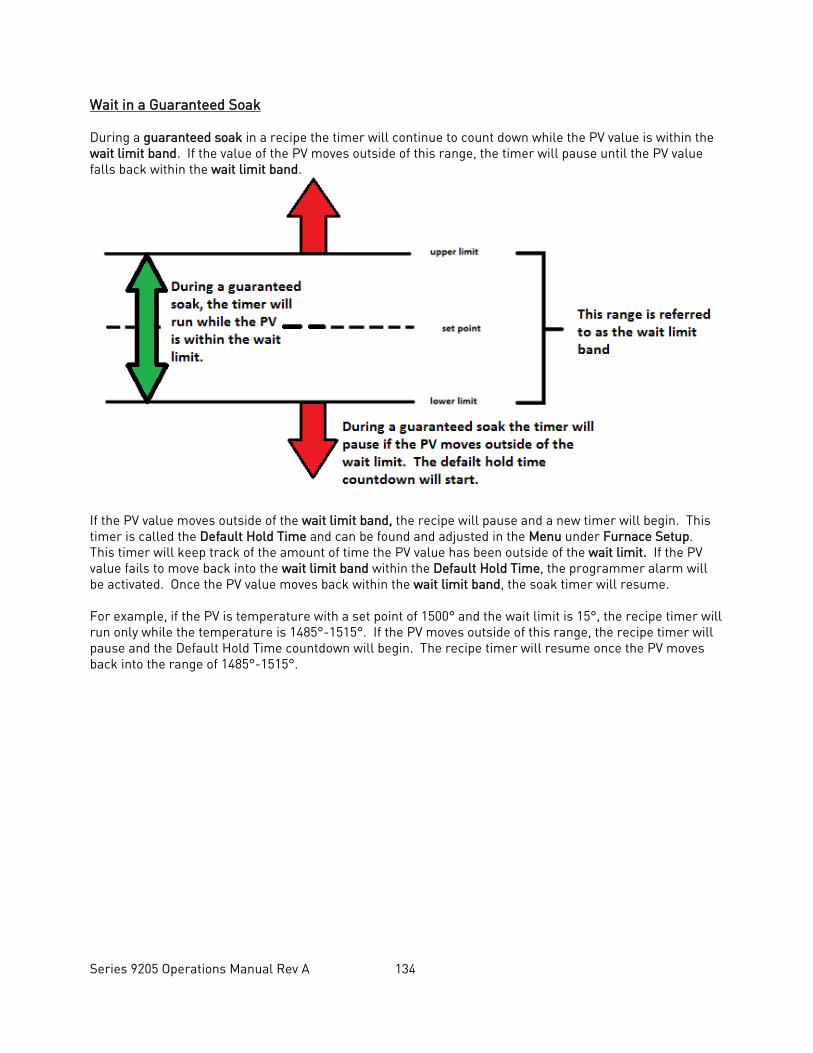
Series 9205 Operations Manual Rev A 134
Wait in a Guaranteed Soak During a guaranteed soak in a recipe the timer will continue to count down while the PV value is within the wait limit band. If the value of the PV moves outside of this range, the timer will pause until the PV value falls back within the wait limit band.
If the PV value moves outside of the wait limit band, the recipe will pause and a new timer will begin. This timer is called the Default Hold Time and can be found and adjusted in the Menu under Furnace Setup. This timer will keep track of the amount of time the PV value has been outside of the wait limit. If the PV value fails to move back into the wait limit band within the Default Hold Time, the programmer alarm will be activated. Once the PV value moves back within the wait limit band, the soak timer will resume. For example, if the PV is temperature with a set point of 1500° and the wait limit is 15°, the recipe timer will run only while the temperature is 1485°-1515°. If the PV moves outside of this range, the recipe timer will pause and the Default Hold Time countdown will begin. The recipe timer will resume once the PV moves back into the range of 1485°-1515°.
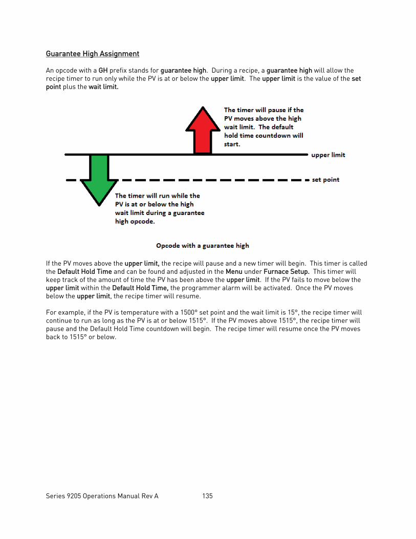
Series 9205 Operations Manual Rev A 135
Guarantee High Assignment An opcode with a GH prefix stands for guarantee high. During a recipe, a guarantee high will allow the recipe timer to run only while the PV is at or below the upper limit. The upper limit is the value of the set point plus the wait limit.
If the PV moves above the upper limit, the recipe will pause and a new timer will begin. This timer is called the Default Hold Time and can be found and adjusted in the Menu under Furnace Setup. This timer will keep track of the amount of time the PV has been above the upper limit. If the PV fails to move below the upper limit within the Default Hold Time, the programmer alarm will be activated. Once the PV moves below the upper limit, the recipe timer will resume. For example, if the PV is temperature with a 1500° set point and the wait limit is 15°, the recipe timer will continue to run as long as the PV is at or below 1515°. If the PV moves above 1515°, the recipe timer will pause and the Default Hold Time countdown will begin. The recipe timer will resume once the PV moves back to 1515° or below.
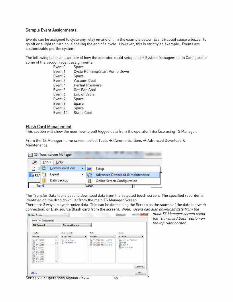
Series 9205 Operations Manual Rev A 136
Sample Event Assignments Events can be assigned to cycle any relay on and off. In the example below, Event 6 could cause a buzzer to go off or a light to turn on, signaling the end of a cycle. However, this is strictly an example. Events are customizable per the system. The following list is an example of how the operator could setup under System Management in Configurator some of the vacuum event assignments.
Event 0 Spare Event 1 Cycle Running/Start Pump Down Event 2 Spare Event 3 Vacuum Cool Event 4 Partial Pressure Event 5 Gas Fan Cool Event 6 End of Cycle Event 7 Spare Event 8 Spare Event 9 Spare Event 10 Static Cool
Flash Card Management This section will show the user how to pull logged data from the operator interface using TS Manager. From the TS Manager home screen, select Tools Communications Advanced Download & Maintenance
The Transfer Data tab is used to download data from the selected touch screen. The specified recorder is identified on the drop down list from the main TS Manager Screen. There are 2 ways to synchronize data. This can be done using the Screen as the source of the data (network connection) or Disk source (flash card from the screen). Note: Users can also download data from the
main TS Manager screen using the “Download Data” button on the top right corner.
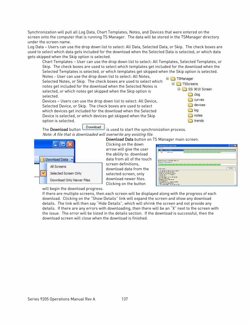
Series 9205 Operations Manual Rev A 137
Synchronization will pull all Log Data, Chart Templates, Notes, and Devices that were entered on the screen onto the computer that is running TS Manager. The data will be stored in the TSManager directory under the screen name. Log Data – Users can use the drop down list to select: All Data, Selected Data, or Skip. The check boxes are used to select which data gets included for the download when the Selected Data is selected, or which data gets skipped when the Skip option is selected.
Chart Templates – User can use the drop down list to select: All Templates, Selected Templates, or Skip. The check boxes are used to select which templates get included for the download when the Selected Templates is selected, or which templates get skipped when the Skip option is selected. Notes - User can use the drop down list to select: All Notes, Selected Notes, or Skip. The check boxes are used to select which notes get included for the download when the Selected Notes is selected, or which notes get skipped when the Skip option is selected. Devices – Users can use the drop down list to select: All Device, Selected Device, or Skip. The check boxes are used to select which devices get included for the download when the Selected Device is selected, or which devices get skipped when the Skip option is selected.
The Download button is used to start the synchronization process. Note: A file that is downloaded will overwrite any existing file.
Download Data button on TS Manager main screen. Clicking on the down arrow will give the user the ability to: download data from all of the touch screen definitions, download data from the selected screen, only download newer files. Clicking on the button
will begin the download progress. If there are multiple screens, then each screen will be displayed along with the progress of each download. Clicking on the “Show Details” link will expand the screen and show any download details. The link will then say “Hide Details”, which will shrink the screen and not provide any details. If there are any errors with downloading, then there will be an “X” next to the screen with the issue. The error will be listed in the details section. If the download is successful, then the download screen will close when the download is finished.
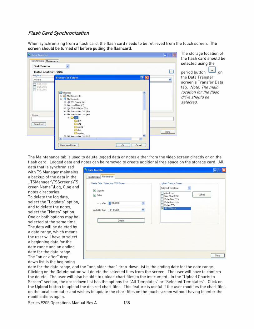
Series 9205 Operations Manual Rev A 138
Flash Card Synchronization When synchronizing from a flash card, the flash card needs to be retrieved from the touch screen. The screen should be turned off before pulling the flashcard.
The storage location of the flash card should be selected using the
period button on the Data Transfer screen’s Transfer Data tab. Note: The main location for the flash drive should be selected.
The Maintenance tab is used to delete logged data or notes either from the video screen directly or on the flash card. Logged data and notes can be removed to create additional free space on the storage card. All data that is synchronized with TS Manager maintains a backup of the data in the ..TSManager\TSScreens\“Screen Name”\Log, Clog and notes directories. To delete the log data, select the “Logdata” option, and to delete the notes, select the “Notes” option. One or both options may be selected at the same time. The data will be deleted by a date range, which means the user will have to select a beginning date for the date range and an ending date for the date range. The “on or after” drop-down list is the beginning date for the date range, and the “and older than” drop-down list is the ending date for the date range. Clicking on the Delete button will delete the selected files from the screen. The user will have to confirm the delete. The user will also be able to upload chart files to the instrument. In the “Upload Charts to Screen” section, the drop-down list has the options for “All Templates” or “Selected Templates”. Click on the Upload button to upload the desired chart files. This feature is useful if the user modifies the chart files on the local computer and wishes to update the chart files on the touch screen without having to enter the modifications again.

Series 9205 Operations Manual Rev A 139
The Done button will close out the screen.
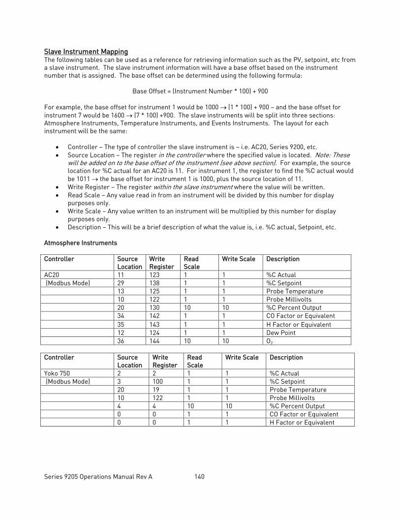
Series 9205 Operations Manual Rev A 140
Slave Instrument Mapping The following tables can be used as a reference for retrieving information such as the PV, setpoint, etc from a slave instrument. The slave instrument information will have a base offset based on the instrument number that is assigned. The base offset can be determined using the following formula:
Base Offset = (Instrument Number * 100) + 900
For example, the base offset for instrument 1 would be 1000 → (1 * 100) + 900 – and the base offset for instrument 7 would be 1600 → (7 * 100) +900. The slave instruments will be split into three sections: Atmosphere Instruments, Temperature Instruments, and Events Instruments. The layout for each instrument will be the same:
• Controller – The type of controller the slave instrument is – i.e. AC20, Series 9200, etc. • Source Location – The register in the controller where the specified value is located. Note: These
will be added on to the base offset of the instrument (see above section). For example, the source location for %C actual for an AC20 is 11. For instrument 1, the register to find the %C actual would be 1011 → the base offset for instrument 1 is 1000, plus the source location of 11.
• Write Register – The register within the slave instrument where the value will be written. • Read Scale – Any value read in from an instrument will be divided by this number for display
purposes only. • Write Scale – Any value written to an instrument will be multiplied by this number for display
purposes only. • Description – This will be a brief description of what the value is, i.e. %C actual, Setpoint, etc.
Atmosphere Instruments Controller Source
Location Write Register
Read Scale
Write Scale Description
AC20 11 123 1 1 %C Actual (Modbus Mode) 29 138 1 1 %C Setpoint 13 125 1 1 Probe Temperature 10 122 1 1 Probe Millivolts 20 130 10 10 %C Percent Output 34 142 1 1 CO Factor or Equivalent 35 143 1 1 H Factor or Equivalent 12 124 1 1 Dew Point 36 144 10 10 O2 Controller Source
Location Write Register
Read Scale
Write Scale Description
Yoko 750 2 2 1 1 %C Actual (Modbus Mode) 3 100 1 1 %C Setpoint 20 19 1 1 Probe Temperature 10 122 1 1 Probe Millivolts 4 4 10 10 %C Percent Output 0 0 1 1 CO Factor or Equivalent 0 0 1 1 H Factor or Equivalent
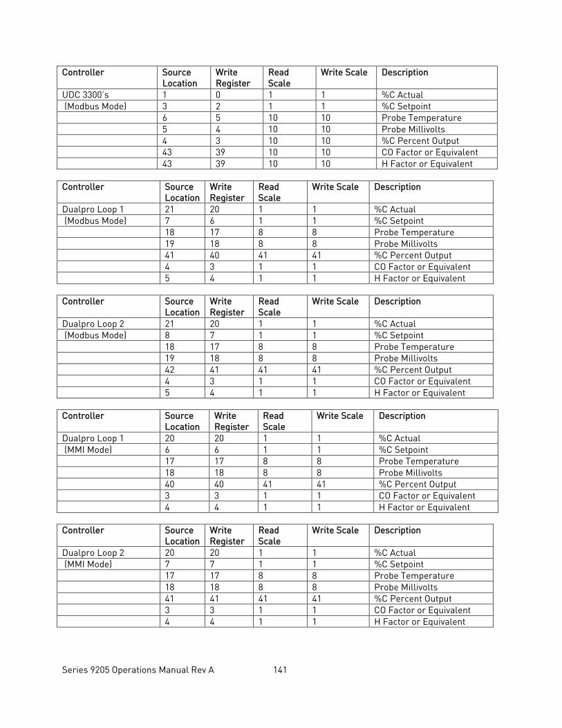
Series 9205 Operations Manual Rev A 141
Controller Source Location
Write Register
Read Scale
Write Scale Description
UDC 3300’s 1 0 1 1 %C Actual (Modbus Mode) 3 2 1 1 %C Setpoint 6 5 10 10 Probe Temperature 5 4 10 10 Probe Millivolts 4 3 10 10 %C Percent Output 43 39 10 10 CO Factor or Equivalent 43 39 10 10 H Factor or Equivalent Controller Source
Location Write Register
Read Scale
Write Scale Description
Dualpro Loop 1 21 20 1 1 %C Actual (Modbus Mode) 7 6 1 1 %C Setpoint 18 17 8 8 Probe Temperature 19 18 8 8 Probe Millivolts 41 40 41 41 %C Percent Output 4 3 1 1 CO Factor or Equivalent 5 4 1 1 H Factor or Equivalent Controller Source
Location Write Register
Read Scale
Write Scale Description
Dualpro Loop 2 21 20 1 1 %C Actual (Modbus Mode) 8 7 1 1 %C Setpoint 18 17 8 8 Probe Temperature 19 18 8 8 Probe Millivolts 42 41 41 41 %C Percent Output 4 3 1 1 CO Factor or Equivalent 5 4 1 1 H Factor or Equivalent Controller Source
Location Write Register
Read Scale
Write Scale Description
Dualpro Loop 1 20 20 1 1 %C Actual (MMI Mode) 6 6 1 1 %C Setpoint 17 17 8 8 Probe Temperature 18 18 8 8 Probe Millivolts 40 40 41 41 %C Percent Output 3 3 1 1 CO Factor or Equivalent 4 4 1 1 H Factor or Equivalent Controller Source
Location Write Register
Read Scale
Write Scale Description
Dualpro Loop 2 20 20 1 1 %C Actual (MMI Mode) 7 7 1 1 %C Setpoint 17 17 8 8 Probe Temperature 18 18 8 8 Probe Millivolts 41 41 41 41 %C Percent Output 3 3 1 1 CO Factor or Equivalent 4 4 1 1 H Factor or Equivalent
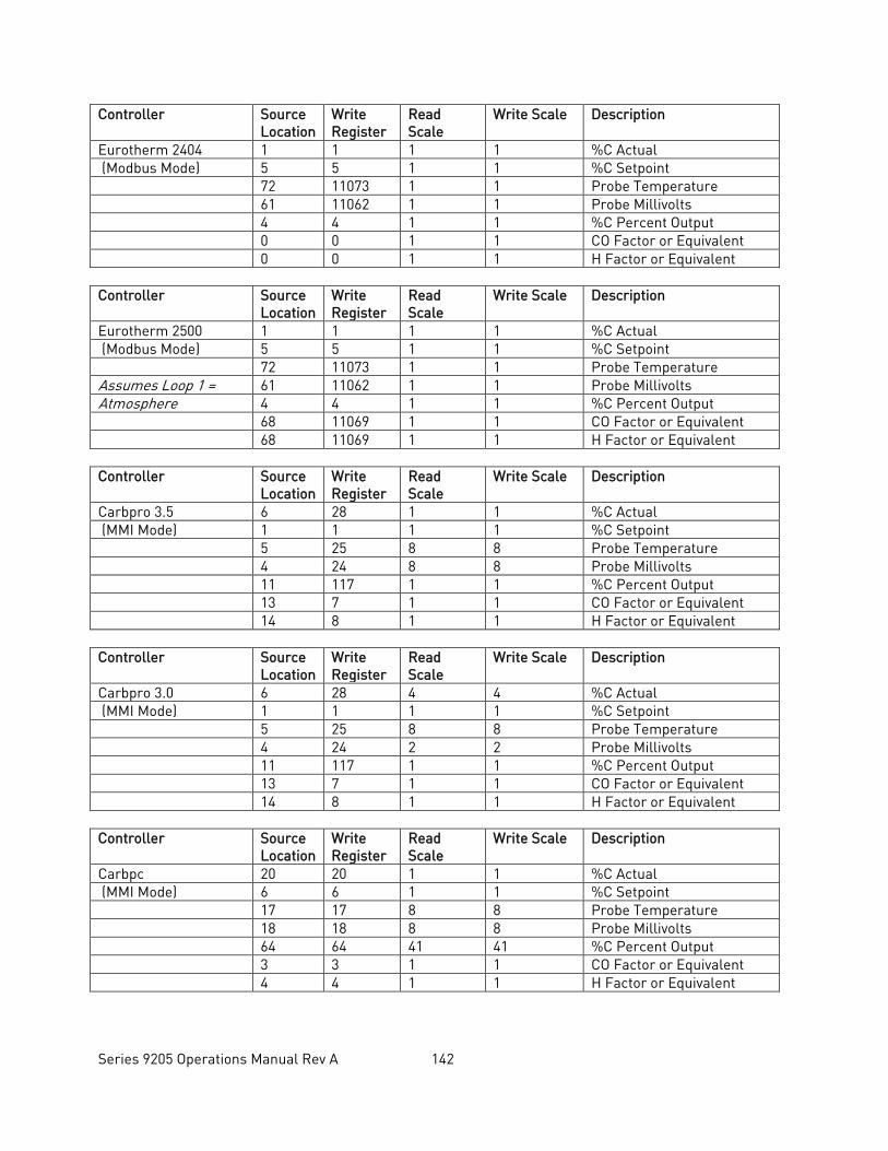
Series 9205 Operations Manual Rev A 142
Controller Source Location
Write Register
Read Scale
Write Scale Description
Eurotherm 2404 1 1 1 1 %C Actual (Modbus Mode) 5 5 1 1 %C Setpoint 72 11073 1 1 Probe Temperature 61 11062 1 1 Probe Millivolts 4 4 1 1 %C Percent Output 0 0 1 1 CO Factor or Equivalent 0 0 1 1 H Factor or Equivalent Controller Source
Location Write Register
Read Scale
Write Scale Description
Eurotherm 2500 1 1 1 1 %C Actual (Modbus Mode) 5 5 1 1 %C Setpoint 72 11073 1 1 Probe Temperature Assumes Loop 1 = 61 11062 1 1 Probe Millivolts Atmosphere 4 4 1 1 %C Percent Output 68 11069 1 1 CO Factor or Equivalent 68 11069 1 1 H Factor or Equivalent Controller Source
Location Write Register
Read Scale
Write Scale Description
Carbpro 3.5 6 28 1 1 %C Actual (MMI Mode) 1 1 1 1 %C Setpoint 5 25 8 8 Probe Temperature 4 24 8 8 Probe Millivolts 11 117 1 1 %C Percent Output 13 7 1 1 CO Factor or Equivalent 14 8 1 1 H Factor or Equivalent Controller Source
Location Write Register
Read Scale
Write Scale Description
Carbpro 3.0 6 28 4 4 %C Actual (MMI Mode) 1 1 1 1 %C Setpoint 5 25 8 8 Probe Temperature 4 24 2 2 Probe Millivolts 11 117 1 1 %C Percent Output 13 7 1 1 CO Factor or Equivalent 14 8 1 1 H Factor or Equivalent Controller Source
Location Write Register
Read Scale
Write Scale Description
Carbpc 20 20 1 1 %C Actual (MMI Mode) 6 6 1 1 %C Setpoint 17 17 8 8 Probe Temperature 18 18 8 8 Probe Millivolts 64 64 41 41 %C Percent Output 3 3 1 1 CO Factor or Equivalent 4 4 1 1 H Factor or Equivalent
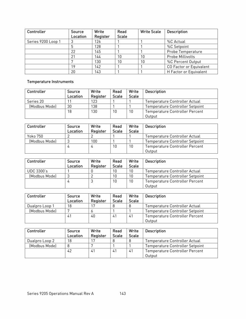
Series 9205 Operations Manual Rev A 143
Controller Source Location
Write Register
Read Scale
Write Scale Description
Series 9200 Loop 1 3 126 1 1 %C Actual 5 128 1 1 %C Setpoint 22 145 1 1 Probe Temperature 21 144 10 10 Probe Millivolts 7 130 10 10 %C Percent Output 19 142 1 1 CO Factor or Equivalent 20 143 1 1 H Factor or Equivalent Temperature Instruments Controller Source
Location Write Register
Read Scale
Write Scale
Description
Series 20 11 123 1 1 Temperature Controller Actual (Modbus Mode) 30 138 1 1 Temperature Controller Setpoint 18 130 10 10 Temperature Controller Percent
Output Controller Source
Location Write Register
Read Scale
Write Scale
Description
Yoko 750 2 2 1 1 Temperature Controller Actual (Modbus Mode) 3 100 1 1 Temperature Controller Setpoint 4 4 10 10 Temperature Controller Percent
Output Controller Source
Location Write Register
Read Scale
Write Scale
Description
UDC 3300’s 1 0 10 10 Temperature Controller Actual (Modbus Mode) 3 2 10 10 Temperature Controller Setpoint 4 3 10 10 Temperature Controller Percent
Output Controller Source
Location Write Register
Read Scale
Write Scale
Description
Dualpro Loop 1 18 17 8 8 Temperature Controller Actual (Modbus Mode) 7 6 1 1 Temperature Controller Setpoint 41 40 41 41 Temperature Controller Percent
Output Controller Source
Location Write Register
Read Scale
Write Scale
Description
Dualpro Loop 2 18 17 8 8 Temperature Controller Actual (Modbus Mode) 8 7 1 1 Temperature Controller Setpoint 42 41 41 41 Temperature Controller Percent
Output
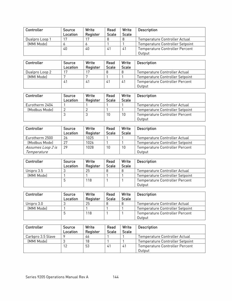
Series 9205 Operations Manual Rev A 144
Controller Source Location
Write Register
Read Scale
Write Scale
Description
Dualpro Loop 1 17 17 8 8 Temperature Controller Actual (MMI Mode) 6 6 1 1 Temperature Controller Setpoint 40 40 41 41 Temperature Controller Percent
Output Controller Source
Location Write Register
Read Scale
Write Scale
Description
Dualpro Loop 2 17 17 8 8 Temperature Controller Actual (MMI Mode) 7 7 1 1 Temperature Controller Setpoint 41 41 41 41 Temperature Controller Percent
Output Controller Source
Location Write Register
Read Scale
Write Scale
Description
Eurotherm 2404 1 1 1 1 Temperature Controller Actual (Modbus Mode) 2 2 1 1 Temperature Controller Setpoint 3 3 10 10 Temperature Controller Percent
Output Controller Source
Location Write Register
Read Scale
Write Scale
Description
Eurotherm 2500 26 1025 1 1 Temperature Controller Actual (Modbus Mode) 27 1026 1 1 Temperature Controller Setpoint Assumes Loop 2 is Temperature
29 1028 10 10 Temperature Controller Percent Output
Controller Source
Location Write Register
Read Scale
Write Scale
Description
Unipro 3.5 3 25 8 8 Temperature Controller Actual (MMI Mode) 1 1 1 1 Temperature Controller Setpoint 5 118 1 1 Temperature Controller Percent
Output Controller Source
Location Write Register
Read Scale
Write Scale
Description
Unipro 3.0 3 25 8 8 Temperature Controller Actual (MMI Mode) 1 1 1 1 Temperature Controller Setpoint 5 118 1 1 Temperature Controller Percent
Output Controller Source
Location Write Register
Read Scale
Write Scale
Description
Carbpro 3.5 Slave 9 46 1 1 Temperature Controller Actual (MMI Mode) 3 18 1 1 Temperature Controller Setpoint 12 53 41 41 Temperature Controller Percent
Output
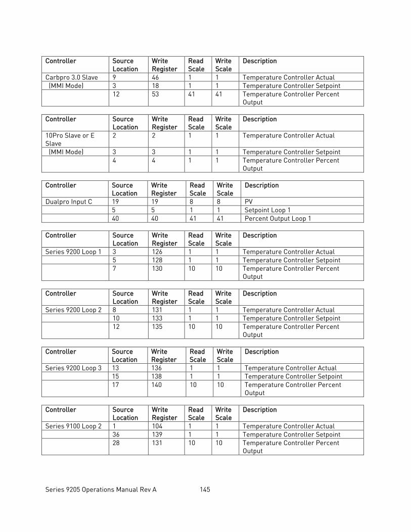
Series 9205 Operations Manual Rev A 145
Controller Source
Location Write Register
Read Scale
Write Scale
Description
Carbpro 3.0 Slave 9 46 1 1 Temperature Controller Actual (MMI Mode) 3 18 1 1 Temperature Controller Setpoint 12 53 41 41 Temperature Controller Percent
Output Controller Source
Location Write Register
Read Scale
Write Scale
Description
10Pro Slave or E Slave
2 2 1 1 Temperature Controller Actual
(MMI Mode) 3 3 1 1 Temperature Controller Setpoint 4 4 1 1 Temperature Controller Percent
Output Controller Source
Location Write Register
Read Scale
Write Scale
Description
Dualpro Input C 19 19 8 8 PV 5 5 1 1 Setpoint Loop 1 40 40 41 41 Percent Output Loop 1 Controller Source
Location Write Register
Read Scale
Write Scale
Description
Series 9200 Loop 1 3 126 1 1 Temperature Controller Actual 5 128 1 1 Temperature Controller Setpoint 7 130 10 10 Temperature Controller Percent
Output Controller Source
Location Write Register
Read Scale
Write Scale
Description
Series 9200 Loop 2 8 131 1 1 Temperature Controller Actual 10 133 1 1 Temperature Controller Setpoint 12 135 10 10 Temperature Controller Percent
Output Controller Source
Location Write Register
Read Scale
Write Scale
Description
Series 9200 Loop 3 13 136 1 1 Temperature Controller Actual 15 138 1 1 Temperature Controller Setpoint 17 140 10 10 Temperature Controller Percent
Output Controller Source
Location Write Register
Read Scale
Write Scale
Description
Series 9100 Loop 2 1 104 1 1 Temperature Controller Actual 36 139 1 1 Temperature Controller Setpoint 28 131 10 10 Temperature Controller Percent
Output
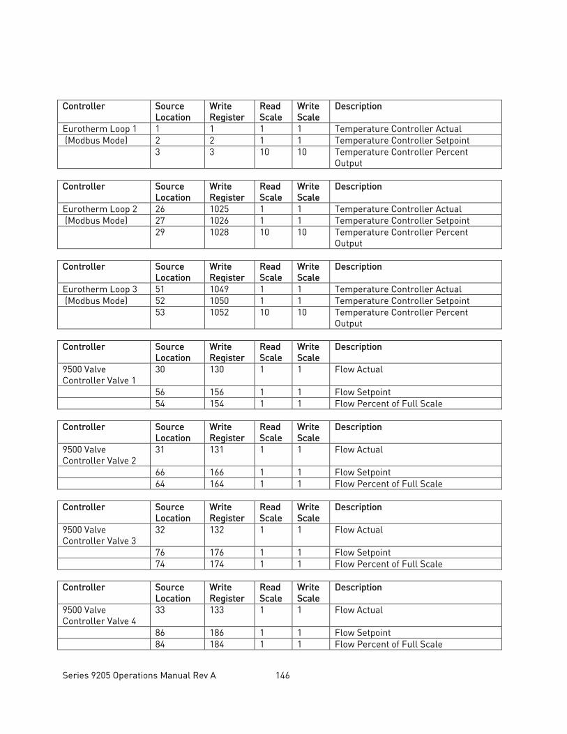
Series 9205 Operations Manual Rev A 146
Controller Source Location
Write Register
Read Scale
Write Scale
Description
Eurotherm Loop 1 1 1 1 1 Temperature Controller Actual (Modbus Mode) 2 2 1 1 Temperature Controller Setpoint 3 3 10 10 Temperature Controller Percent
Output Controller Source
Location Write Register
Read Scale
Write Scale
Description
Eurotherm Loop 2 26 1025 1 1 Temperature Controller Actual (Modbus Mode) 27 1026 1 1 Temperature Controller Setpoint 29 1028 10 10 Temperature Controller Percent
Output Controller Source
Location Write Register
Read Scale
Write Scale
Description
Eurotherm Loop 3 51 1049 1 1 Temperature Controller Actual (Modbus Mode) 52 1050 1 1 Temperature Controller Setpoint 53 1052 10 10 Temperature Controller Percent
Output Controller Source
Location Write Register
Read Scale
Write Scale
Description
9500 Valve Controller Valve 1
30 130 1 1 Flow Actual
56 156 1 1 Flow Setpoint 54 154 1 1 Flow Percent of Full Scale Controller Source
Location Write Register
Read Scale
Write Scale
Description
9500 Valve Controller Valve 2
31 131 1 1 Flow Actual
66 166 1 1 Flow Setpoint 64 164 1 1 Flow Percent of Full Scale Controller Source
Location Write Register
Read Scale
Write Scale
Description
9500 Valve Controller Valve 3
32 132 1 1 Flow Actual
76 176 1 1 Flow Setpoint 74 174 1 1 Flow Percent of Full Scale Controller Source
Location Write Register
Read Scale
Write Scale
Description
9500 Valve Controller Valve 4
33 133 1 1 Flow Actual
86 186 1 1 Flow Setpoint 84 184 1 1 Flow Percent of Full Scale
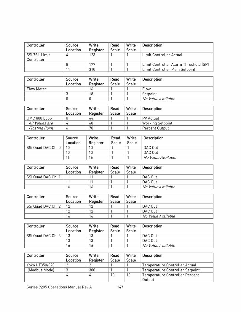
Series 9205 Operations Manual Rev A 147
Controller Source
Location Write Register
Read Scale
Write Scale
Description
SSi 7SL Limit Controller
4 123 1 1 Limit Controller Actual
8 177 1 1 Limit Controller Alarm Threshold (SP) 11 310 1 1 Limit Controller Main Setpoint Controller Source
Location Write Register
Read Scale
Write Scale
Description
Flow Meter 1 16 1 1 Flow 3 18 1 1 Setpoint 0 0 1 1 No Value Available Controller Source
Location Write Register
Read Scale
Write Scale
Description
UMC 800 Loop 1 0 64 1 1 PV Actual All Values are 4 68 1 1 Working Setpoint Floating Point 6 70 1 1 Percent Output Controller Source
Location Write Register
Read Scale
Write Scale
Description
SSi Quad DAC Ch. 0 10 10 1 1 DAC Out 10 10 1 1 DAC Out 16 16 1 1 No Value Available Controller Source
Location Write Register
Read Scale
Write Scale
Description
SSi Quad DAC Ch. 1 11 11 1 1 DAC Out 11 11 1 1 DAC Out 16 16 1 1 No Value Available Controller Source
Location Write Register
Read Scale
Write Scale
Description
SSi Quad DAC Ch. 2 12 12 1 1 DAC Out 12 12 1 1 DAC Out 16 16 1 1 No Value Available Controller Source
Location Write Register
Read Scale
Write Scale
Description
SSi Quad DAC Ch. 3 13 13 1 1 DAC Out 13 13 1 1 DAC Out 16 16 1 1 No Value Available Controller Source
Location Write Register
Read Scale
Write Scale
Description
Yoko UT350/320 2 2 1 1 Temperature Controller Actual (Modbus Mode) 3 300 1 1 Temperature Controller Setpoint 4 4 10 10 Temperature Controller Percent
Output
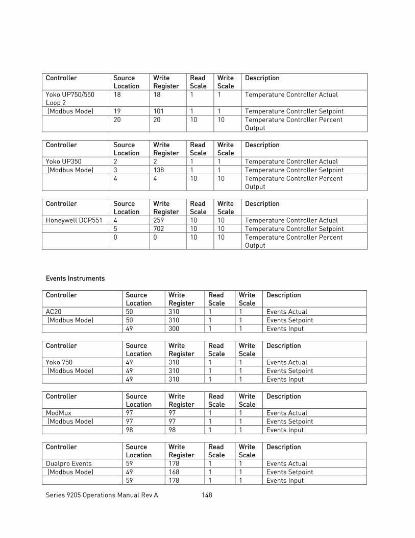
Series 9205 Operations Manual Rev A 148
Controller Source
Location Write Register
Read Scale
Write Scale
Description
Yoko UP750/550 Loop 2
18 18 1 1 Temperature Controller Actual
(Modbus Mode) 19 101 1 1 Temperature Controller Setpoint 20 20 10 10 Temperature Controller Percent
Output Controller Source
Location Write Register
Read Scale
Write Scale
Description
Yoko UP350 2 2 1 1 Temperature Controller Actual (Modbus Mode) 3 138 1 1 Temperature Controller Setpoint 4 4 10 10 Temperature Controller Percent
Output Controller Source
Location Write Register
Read Scale
Write Scale
Description
Honeywell DCP551 4 259 10 10 Temperature Controller Actual 5 702 10 10 Temperature Controller Setpoint 0 0 10 10 Temperature Controller Percent
Output Events Instruments Controller Source
Location Write Register
Read Scale
Write Scale
Description
AC20 50 310 1 1 Events Actual (Modbus Mode) 50 310 1 1 Events Setpoint 49 300 1 1 Events Input Controller Source
Location Write Register
Read Scale
Write Scale
Description
Yoko 750 49 310 1 1 Events Actual (Modbus Mode) 49 310 1 1 Events Setpoint 49 310 1 1 Events Input Controller Source
Location Write Register
Read Scale
Write Scale
Description
ModMux 97 97 1 1 Events Actual (Modbus Mode) 97 97 1 1 Events Setpoint 98 98 1 1 Events Input Controller Source
Location Write Register
Read Scale
Write Scale
Description
Dualpro Events 59 178 1 1 Events Actual (Modbus Mode) 49 168 1 1 Events Setpoint 59 178 1 1 Events Input
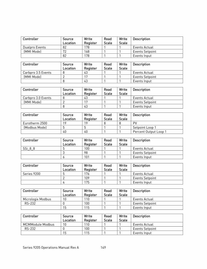
Series 9205 Operations Manual Rev A 149
Controller Source
Location Write Register
Read Scale
Write Scale
Description
Dualpro Events 82 178 1 1 Events Actual (MMI Mode) 72 168 1 1 Events Setpoint 82 178 1 1 Events Input Controller Source
Location Write Register
Read Scale
Write Scale
Description
Carbpro 3.5 Events 8 43 1 1 Events Actual (MMI Mode) 2 17 1 1 Events Setpoint 8 43 1 1 Events Input Controller Source
Location Write Register
Read Scale
Write Scale
Description
Carbpro 3.0 Events 8 43 1 1 Events Actual (MMI Mode) 2 17 1 1 Events Setpoint 8 43 1 1 Events Input Controller Source
Location Write Register
Read Scale
Write Scale
Description
Eurotherm 2500 19 19 8 8 PV (Modbus Mode) 5 5 1 1 Setpoint Loop 1 40 40 1 1 Percent Output Loop 1 Controller Source
Location Write Register
Read Scale
Write Scale
Description
SSi_8_8 5 100 1 1 Events Actual 3 98 1 1 Events Setpoint 6 101 1 1 Events Input Controller Source
Location Write Register
Read Scale
Write Scale
Description
Series 9200 5 176 1 1 Events Actual 2 109 1 1 Events Setpoint 4 175 1 1 Events Input Controller Source
Location Write Register
Read Scale
Write Scale
Description
Micrologix Modbus 10 110 1 1 Events Actual RS-232 0 100 1 1 Events Setpoint 15 115 1 1 Events Input Controller Source
Location Write Register
Read Scale
Write Scale
Description
MCMModule Modbus 10 110 1 1 Events Actual RS-232 0 100 1 1 Events Setpoint 15 115 1 1 Events Input
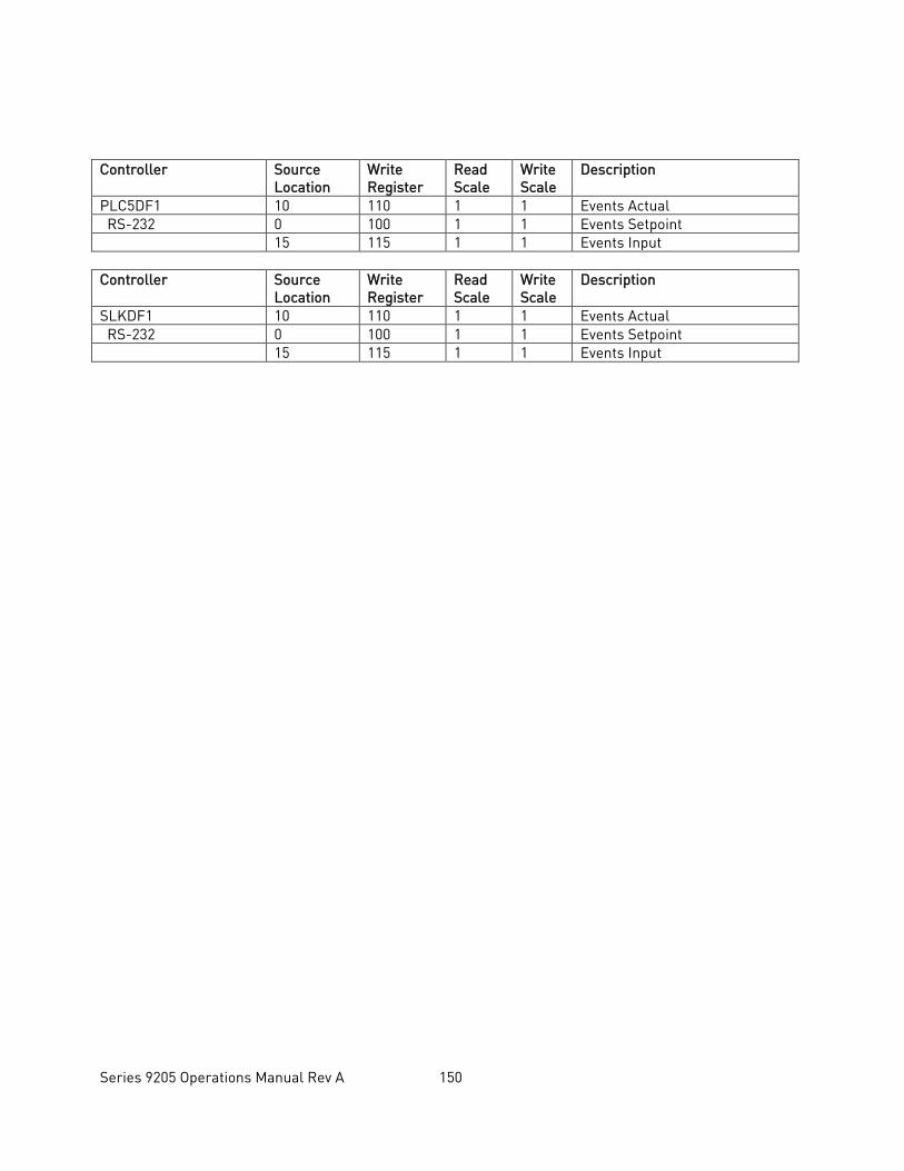
Series 9205 Operations Manual Rev A 150
Controller Source
Location Write Register
Read Scale
Write Scale
Description
PLC5DF1 10 110 1 1 Events Actual RS-232 0 100 1 1 Events Setpoint 15 115 1 1 Events Input Controller Source
Location Write Register
Read Scale
Write Scale
Description
SLKDF1 10 110 1 1 Events Actual RS-232 0 100 1 1 Events Setpoint 15 115 1 1 Events Input
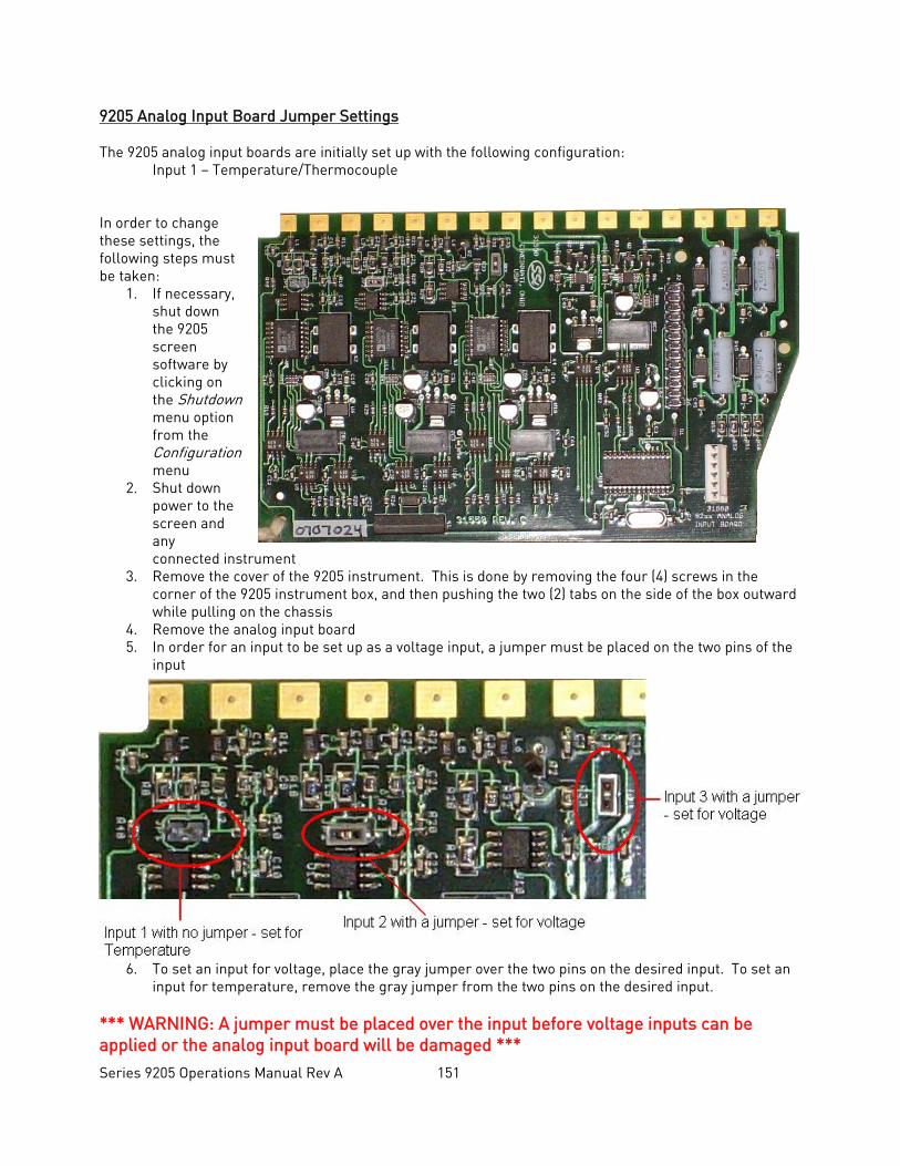
Series 9205 Operations Manual Rev A 151
9205 Analog Input Board Jumper Settings The 9205 analog input boards are initially set up with the following configuration: Input 1 – Temperature/Thermocouple In order to change these settings, the following steps must be taken:
1. If necessary, shut down the 9205 screen software by clicking on the Shutdown menu option from the Configuration menu
2. Shut down power to the screen and any connected instrument
3. Remove the cover of the 9205 instrument. This is done by removing the four (4) screws in the corner of the 9205 instrument box, and then pushing the two (2) tabs on the side of the box outward while pulling on the chassis
4. Remove the analog input board 5. In order for an input to be set up as a voltage input, a jumper must be placed on the two pins of the
input
6. To set an input for voltage, place the gray jumper over the two pins on the desired input. To set an input for temperature, remove the gray jumper from the two pins on the desired input.
*** WARNING: A jumper must be placed over the input before voltage inputs can be applied or the analog input board will be damaged ***
Series 9205 Operations Manual Rev A 152
7. Re-insert the analog input board 8. Replace the cover on the 9205 instrument 9. Re-attach the power to the screen and any connected device 10. Power up the Advantech Touchscreen 11. From the Analog Input Setup menu screen, select the appropriate input and change the T/C Type to
the correct type Contact Super Systems Inc at 513-772-0060 if there are any questions or problems.
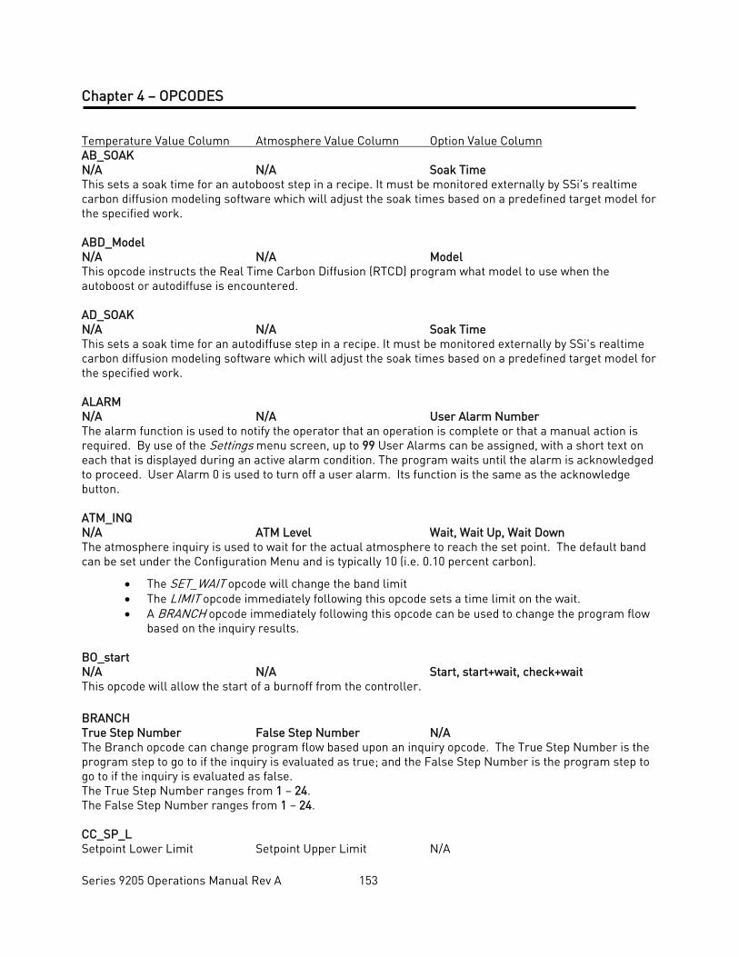
Series 9205 Operations Manual Rev A 153
Chapter 4 – OPCODES Temperature Value Column Atmosphere Value Column Option Value Column AB_SOAK N/A N/A Soak Time This sets a soak time for an autoboost step in a recipe. It must be monitored externally by SSi's realtime carbon diffusion modeling software which will adjust the soak times based on a predefined target model for the specified work. ABD_Model N/A N/A Model This opcode instructs the Real Time Carbon Diffusion (RTCD) program what model to use when the autoboost or autodiffuse is encountered. AD_SOAK N/A N/A Soak Time This sets a soak time for an autodiffuse step in a recipe. It must be monitored externally by SSi's realtime carbon diffusion modeling software which will adjust the soak times based on a predefined target model for the specified work. ALARM N/A N/A User Alarm Number The alarm function is used to notify the operator that an operation is complete or that a manual action is required. By use of the Settings menu screen, up to 99 User Alarms can be assigned, with a short text on each that is displayed during an active alarm condition. The program waits until the alarm is acknowledged to proceed. User Alarm 0 is used to turn off a user alarm. Its function is the same as the acknowledge button. ATM_INQ N/A ATM Level Wait, Wait Up, Wait Down The atmosphere inquiry is used to wait for the actual atmosphere to reach the set point. The default band can be set under the Configuration Menu and is typically 10 (i.e. 0.10 percent carbon).
• The SET_WAIT opcode will change the band limit • The LIMIT opcode immediately following this opcode sets a time limit on the wait. • A BRANCH opcode immediately following this opcode can be used to change the program flow
based on the inquiry results. BO_start N/A N/A Start, start+wait, check+wait This opcode will allow the start of a burnoff from the controller. BRANCH True Step Number False Step Number N/A The Branch opcode can change program flow based upon an inquiry opcode. The True Step Number is the program step to go to if the inquiry is evaluated as true; and the False Step Number is the program step to go to if the inquiry is evaluated as false. The True Step Number ranges from 1 – 24. The False Step Number ranges from 1 – 24. CC_SP_L Setpoint Lower Limit Setpoint Upper Limit N/A
Series 9205 Operations Manual Rev A 154
The Cascade Setpoint Limit opcode will allow the use to set the upper and lower limits for the cascade setpoint. The temperature data is the lower limit, and the atmosphere data is the upper limit. DELAY N/A N/A Delay Time This opcode is used when a short delay is needed. The option value is the delay time in seconds, from 1-500 seconds. DEV_AL Temperature Dev/Band Atmosphere Dev/Band Loop The deviation alarm opcode is used to turn the temperature or vacuum deviation alarms ON or OFF. The Temperature Dev/ Band will determine the deviation band for the temperature deviation alarm. The Loop will determine which type of deviation alarm to use. The Temperature Dev/Band ranges from -301 (Disable) – 30000. The Loop options are: Off, T. Bnd (Temperature Band), A. Bnd (Atmosphere Band), A. Bnd, T. Bnd (Atmosphere Band and Temperature Band), T. + Dev (Temperature + Deviation), T. – Dev (Temperature – Deviation), A. Bnd, T. + Dev (Atmosphere Band and Temperature + Deviation), A. Bnd, T. – Dev (Atmosphere Band and Temperature – Deviation), A. + Dev (Atmosphere + Deviation), A. + Dev, T. Bnd (Atmosphere + Deviation and Temperature Band), A. + Dev, T. + Dev (Atmosphere + Deviation and Temperature + Deviation), A. + Dev, T. – Dev (Atmosphere + Deviation and Temperature – Deviation), A. – Dev (Atmosphere – Deviation), A. – Dev, T. Bnd (Atmosphere – Deviation and Temperature Band), A. – Dev, T. + Dev (Atmosphere – Deviation and Temperature + Deviation), A. – Dev, T. – Dev (Atmosphere – Deviation and Temperature – Deviation). There is also an option for Smart Temp and Smart Atm. The band limit can be changed by the SET_WAIT opcode. DOW_INQ N/A N/A Day This opcode checks the real time clock for the day of the week. This is useful for performing operations on a weekly basis on a specific day. The Day is the day of the week, i.e. Sunday, Monday, Tuesday, Wednesday, Thursday, Friday, or Saturday. EVT_IN Temperature Setpoint Atmosphere Setpoint Event This opcode waits for an input event to be turned ON or OFF depending on the Event value selected. If the Temperature Setpoint is specified, it is considered a set point and will be sent to the appropriate controller. The Temperature Setpoint ranges from -301 (Disable) – 30000. The Atmosphere Setpoint ranges from -0.01 to 99.99. The Event options are: Event 0 ON/OFF – Event 31 ON/OFF. EVT_OUT Temperature Setpoint N/A Event This opcode waits for an output event to be turned ON or OFF depending on the Event value selected. If the Temperature Setpoint is specified, it is considered a set point and will be sent to the appropriate controller. The Temperature Setpoint ranges from -301 (Disable) – 30000. The Event options are: Event 0 ON/OFF – Event 15 ON/OFF. G_SOAK N/A Wait Limit Soak Time This is a guaranteed soak opcode. The temperature process value must be within the deviation band to allow the soak timer to run. If the temperature process value goes out of the deviation band, then the soak timer will stop and wait until the temperature process value comes back into the deviation band before starting up again.
Series 9205 Operations Manual Rev A 155
The Wait Limit is the wait time, in Hours: Minutes format, for the wait limit. The Hours range from 0 – 533, and the Minutes range from 0 – 59. The Soak time is the total time, in Hours:Minutes format, for the soak to run. The Hours range from 0 – 166, and the Minutes range from 0 – 59. The band limit can be changed by the SET_WAIT opcode. GDELAY N/A N/A Delay Time This opcode is a guaranteed short delay. It guarantees on the temperature loop unless the load TCs are enabled, in which case it guarantees against the load TC map for the specified number of seconds. The Delay Time is from 1 – 500 seconds. GHDELAY N/A N/A Delay Time This opcode is a guaranteed high short delay opcode. The temperature process value must be below the high limit deviation band to allow the delay timer to run. If the temperature process value goes out of the deviation band, then the delay timer will stop and wait until the temperature process value comes back into the deviation band before starting up again. The Delay Time is from 1 – 500 seconds. GHSOAK N/A Wait Limit Soak Time This is a guaranteed soak high opcode. The temperature process value must be above the deviation band to allow the soak timer to run. If the temperature process value goes out of the deviation band, then the soak timer will stop and wait until the temperature process value comes back into the deviation band before starting up again. The Wait Limit is the wait time, in Hours: Minutes format, for the wait limit. The Hours range from 0 – 167, and the Minutes range from 0 – 59. The Soak time is the total time, in Hours:Minutes format, for the soak to run. The Hours range from 0 – 166, and the Minutes range from 0 – 59. The band limit can be changed by the SET_WAIT opcode. GHZDELAY N/A N/A Delay Time This is a guaranteed high short delay opcode for a zone. The temperature process value must be below the high limit deviation band to allow the delay timer to run. If the temperature process value goes out of the deviation band, then the delay timer will stop and wait until the temperature process value comes back into the deviation band before starting up again. The Delay Time is from 1 – 500 seconds. GHZSOAK N/A Wait Limit Soak Time This is a guaranteed soak high opcode for a zone. The temperature process value must be below the high limit deviation band to allow the soak timer to run. If the temperature process value goes out of the deviation band, then the soak timer will stop and wait until the temperature process value comes back into the deviation band before starting up again. The Wait Limit is the wait time, in Hours: Minutes format, for the wait limit. The Hours range from 0 – 533, and the Minutes range from 0 – 59. The Soak time is the total time, in Hours:Minutes format, for the soak to run. The Hours range from 0 – 166, and the Minutes range from 0 – 59. The band limit can be changed by the SET_WAIT opcode. GLDELAY N/A N/A Delay Time
Series 9205 Operations Manual Rev A 156
This opcode is a guaranteed low short delay opcode. The temperature process value must be above the lower limit deviation band to allow the delay timer to run. If the temperature process value goes out of the deviation band, then the delay timer will stop and wait until the temperature process value comes back into the deviation band before starting up again. The Delay Time is from 1 – 500 seconds. GLSOAK N/A Wait Limit Soak Time This is a guaranteed soak low opcode. The temperature process value must be above the lower limit deviation band to allow the soak timer to run. If the temperature process value goes out of the deviation band, then the soak timer will stop and wait until the temperature process value comes back into the deviation band before starting up again. The Wait Limit is the wait time, in Hours: Minutes format, for the wait limit. The Hours range from 0 – 533, and the Minutes range from 0 – 59. The Soak time is the total time, in Hours:Minutes format, for the soak to run. The Hours range from 0 – 166, and the Minutes range from 0 – 59. The band limit can be changed by the SET_WAIT opcode. GLZDELAY N/A N/A Delay Time This is a guaranteed low short delay opcode for a zone. The temperature process value must be below the deviation band to allow the delay timer to run. If the temperature process value goes out of the deviation band, then the delay timer will stop and wait until the temperature process value comes back into the deviation band before starting up again. The Delay Time is from 1 – 500 seconds. GLZSOAK N/A Wait Limit Soak Time This is a guaranteed soak low opcode for a zone. The temperature process value must be above the lower limit deviation band to allow the soak timer to run. If the temperature process value goes out of the deviation band, then the soak timer will stop and wait until the temperature process value comes back into the deviation band before starting up again. The Wait Limit is the wait time, in Hours: Minutes format, for the wait limit. The Hours range from 0 – 533, and the Minutes range from 0 – 59. The Soak time is the total time, in Hours:Minutes format, for the soak to run. The Hours range from 0 – 166, and the Minutes range from 0 – 59. The band limit can be changed by the SET_WAIT opcode. GOSUB N/A N/A Recipe Number The go to subroutine opcode is used to call a program to run and then return to the calling program. This is used to execute standard routines that can be used by many programs. GOSUBs can be stacked up to eight (8) levels. The Recipe Number is the recipe (program) to run. The range is 1 – 300.
GRAMP Temperature Setpoint Atmosphere Setpoint Time This is a guaranteed ramp opcode. The process value must be within the deviation band to allow the ramp timer to run. If the process value goes out of the deviation band, then the ramp timer will stop and wait until the process value comes back into the deviation band before starting up again. The Temperature Setpoint is the setpoint to send for the temperature process variable. The range is -301 (disable) – 30000. The Atmosphere setpoint is the setpoint to send for the atmosphere process variable. The range is -0.01 to 99.99.
Series 9205 Operations Manual Rev A 157
The Time is the total time for the program to reach the desired setpoint(s), in Hours:Minutes format. The Hours range from 0 – 166, and the Minutes range from 0 – 59. The band limit can be changed by the SET_WAIT opcode.
GTCINQDEL Delay Time T/C Option This is a guaranteed TC inquiry short delay opcode. It is used to verify that all active thermocouples are within the set wait limits around the setpoint for the user defined time period. The Delay Time is the time in seconds before checking the T/Cs. The range is 0 – 500. The T/C is the Control T/C or Load T/C to use. The options are: Control T/C, T/C 1 – T/C 24. The Option will allow the user to wait for the T/Cs to come within the set wait limits around the setpoint. The options are: Wait, Wait Up, or Wait Down. GZ_SOAK N/A N/A Soak Time This is a guaranteed soak opcode for a zone. The temperature process value must be within the deviation band to allow the soak timer to run. If the temperature process value goes out of the deviation band, then the soak timer will stop and wait until the temperature process value comes back into the deviation band before starting up again. The Soak time is the total time, in Hours:Minutes format, for the soak to run. The Hours range from 0 – 166, and the Minutes range from 0 – 59. The band limit can be changed by the SET_WAIT opcode.
GZDELAY N/A N/A Delay Time This is a guaranteed short delay opcode for a zone. The temperature process value must be within the deviation band to allow the delay timer to run. If the temperature process value goes out of the deviation band, then the soak timer will stop and wait until the temperature process value comes back into the deviation band before starting up again. The Delay Time is from 1 – 500 seconds.
GZRAMP Temperature Setpoint Atmosphere Setpoint Time This is a guaranteed ramp opcode for a zone. The process value must be within the deviation band to allow the ramp timer to run. If the temperature process value goes out of the deviation band, then the ramp timer will stop and wait until the temperature process value comes back into the deviation band before starting up again. The Temperature Setpoint is the setpoint to send for the temperature process variable. The range is -301 (disable) to 30000. The Time is the total time for the program to reach the desired setpoint(s), in Hours:Minutes format. The Hours range from 0 – 166, and the Minutes range from 0 – 59. The band limit can be changed by the SET_WAIT opcode. HIGH_AL Temperature Setpoint Atmosphere Setpoint N/A This opcode is used to enable a high limit alarm on the temperature or atmosphere process. This alarm remains active until the program ends. The Temperature Setpoint is the setpoint to send for the temperature process variable. The range is -301 (disable) to 30000. The Atmosphere Setpoint is the setpoint to send for the atmosphere process variable. The range is -0.01 (disable) to 99.99. HIGH_PO Temperature PO Value Atmosphere PO Value N/A
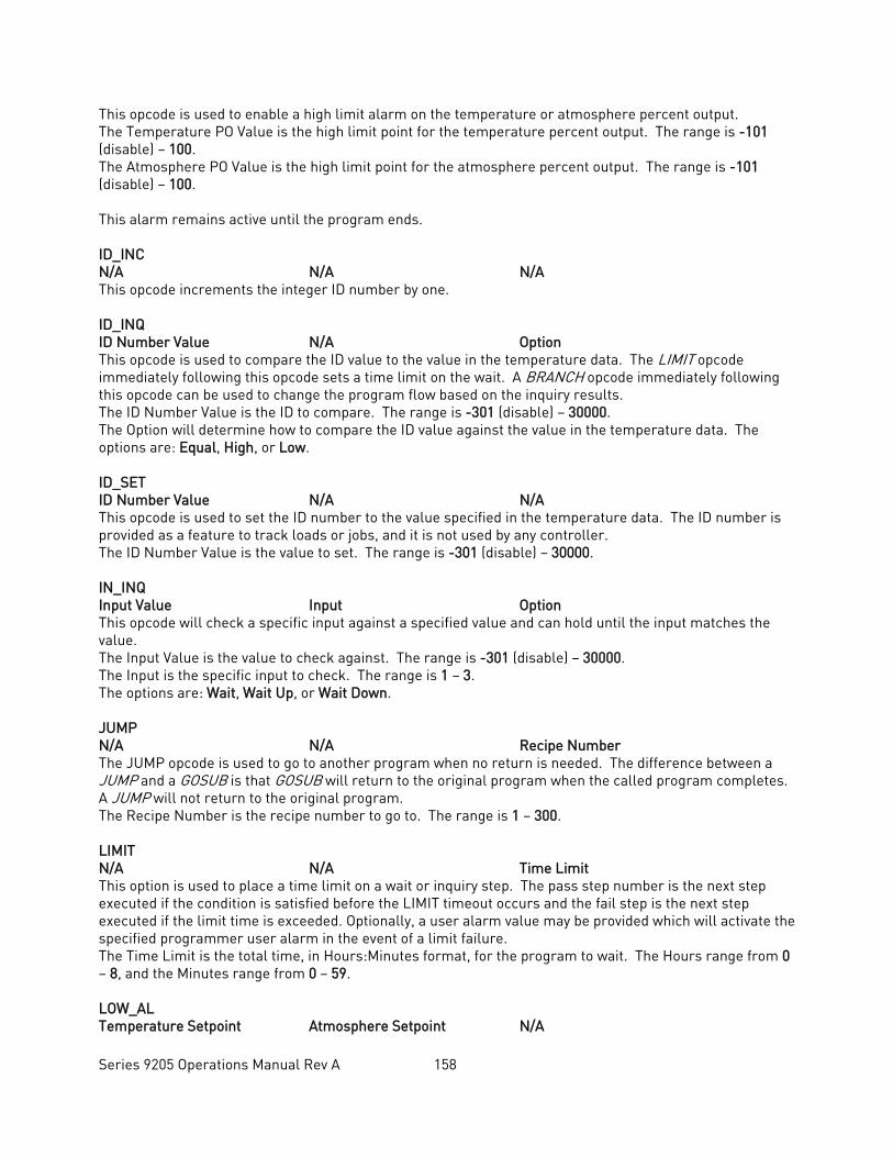
Series 9205 Operations Manual Rev A 158
This opcode is used to enable a high limit alarm on the temperature or atmosphere percent output. The Temperature PO Value is the high limit point for the temperature percent output. The range is -101 (disable) – 100. The Atmosphere PO Value is the high limit point for the atmosphere percent output. The range is -101 (disable) – 100. This alarm remains active until the program ends. ID_INC N/A N/A N/A This opcode increments the integer ID number by one. ID_INQ ID Number Value N/A Option This opcode is used to compare the ID value to the value in the temperature data. The LIMIT opcode immediately following this opcode sets a time limit on the wait. A BRANCH opcode immediately following this opcode can be used to change the program flow based on the inquiry results. The ID Number Value is the ID to compare. The range is -301 (disable) – 30000. The Option will determine how to compare the ID value against the value in the temperature data. The options are: Equal, High, or Low. ID_SET ID Number Value N/A N/A This opcode is used to set the ID number to the value specified in the temperature data. The ID number is provided as a feature to track loads or jobs, and it is not used by any controller. The ID Number Value is the value to set. The range is -301 (disable) – 30000. IN_INQ Input Value Input Option This opcode will check a specific input against a specified value and can hold until the input matches the value. The Input Value is the value to check against. The range is -301 (disable) – 30000. The Input is the specific input to check. The range is 1 – 3. The options are: Wait, Wait Up, or Wait Down. JUMP N/A N/A Recipe Number The JUMP opcode is used to go to another program when no return is needed. The difference between a JUMP and a GOSUB is that GOSUB will return to the original program when the called program completes. A JUMP will not return to the original program. The Recipe Number is the recipe number to go to. The range is 1 – 300. LIMIT N/A N/A Time Limit This option is used to place a time limit on a wait or inquiry step. The pass step number is the next step executed if the condition is satisfied before the LIMIT timeout occurs and the fail step is the next step executed if the limit time is exceeded. Optionally, a user alarm value may be provided which will activate the specified programmer user alarm in the event of a limit failure. The Time Limit is the total time, in Hours:Minutes format, for the program to wait. The Hours range from 0 – 8, and the Minutes range from 0 – 59. LOW_AL Temperature Setpoint Atmosphere Setpoint N/A
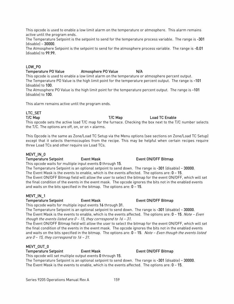
Series 9205 Operations Manual Rev A 159
This opcode is used to enable a low limit alarm on the temperature or atmosphere. This alarm remains active until the program ends. The Temperature Setpoint is the setpoint to send for the temperature process variable. The range is -301 (disable) – 30000. The Atmosphere Setpoint is the setpoint to send for the atmosphere process variable. The range is -0.01 (disable) to 99.99. LOW_PO Temperature PO Value Atmosphere PO Value N/A This opcode is used to enable a low limit alarm on the temperature or atmosphere percent output. The Temperature PO Value is the high limit point for the temperature percent output. The range is -101 (disable) to 100. The Atmosphere PO Value is the high limit point for the temperature percent output. The range is -101 (disable) to 100. This alarm remains active until the program ends. LTC_SET T/C Map T/C Map Load TC Enable This opcode sets the active load T/C map for the furnace. Checking the box next to the T/C number selects the T/C. The options are off, on, or on + alarms. This Opcode is the same as Zone/Load TC Setup via the Menu options (see sections on Zone/Load TC Setup) except that it selects thermocouples from the recipe. This may be helpful when certain recipes require three Load TCs and other require six Load TCs. MEVT_IN_0 Temperature Setpoint Event Mask Event ON/OFF Bitmap This opcode waits for multiple input events 0 through 15. The Temperature Setpoint is an optional setpoint to send down. The range is -301 (disable) – 30000. The Event Mask is the events to enable, which is the events affected. The options are: 0 – 15. The Event ON/OFF Bitmap field will allow the user to select the bitmap for the event ON/OFF, which will set the final condition of the events in the event mask. The opcode ignores the bits not in the enabled events and waits on the bits specified in the bitmap. The options are: 0 – 15. MEVT_IN_1 Temperature Setpoint Event Mask Event ON/OFF Bitmap This opcode waits for multiple input events 16 through 31. The Temperature Setpoint is an optional setpoint to send down. The range is -301 (disable) – 30000. The Event Mask is the events to enable, which is the events affected. The options are: 0 – 15. Note – Even though the events listed are 0 – 15, they correspond to 16 – 31. The Event ON/OFF Bitmap field will allow the user to select the bitmap for the event ON/OFF, which will set the final condition of the events in the event mask. The opcode ignores the bits not in the enabled events and waits on the bits specified in the bitmap. The options are: 0 – 15. Note – Even though the events listed are 0 – 15, they correspond to 16 – 31. MEVT_OUT_0 Temperature Setpoint Event Mask Event ON/OFF Bitmap This opcode will set multiple output events 0 through 15. The Temperature Setpoint is an optional setpoint to send down. The range is -301 (disable) – 30000. The Event Mask is the events to enable, which is the events affected. The options are: 0 – 15.
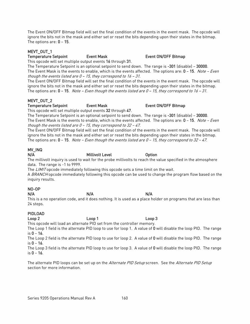
Series 9205 Operations Manual Rev A 160
The Event ON/OFF Bitmap field will set the final condition of the events in the event mask. The opcode will ignore the bits not in the mask and either set or reset the bits depending upon their states in the bitmap. The options are: 0 – 15. MEVT_OUT_1 Temperature Setpoint Event Mask Event ON/OFF Bitmap This opcode will set multiple output events 16 through 31. The Temperature Setpoint is an optional setpoint to send down. The range is -301 (disable) – 30000. The Event Mask is the events to enable, which is the events affected. The options are: 0 – 15. Note – Even though the events listed are 0 – 15, they correspond to 16 – 31. The Event ON/OFF Bitmap field will set the final condition of the events in the event mask. The opcode will ignore the bits not in the mask and either set or reset the bits depending upon their states in the bitmap. The options are: 0 – 15. Note – Even though the events listed are 0 – 15, they correspond to 16 – 31. MEVT_OUT_2 Temperature Setpoint Event Mask Event ON/OFF Bitmap This opcode will set multiple output events 32 through 47. The Temperature Setpoint is an optional setpoint to send down. The range is -301 (disable) – 30000. The Event Mask is the events to enable, which is the events affected. The options are: 0 – 15. Note – Even though the events listed are 0 – 15, they correspond to 32 – 47. The Event ON/OFF Bitmap field will set the final condition of the events in the event mask. The opcode will ignore the bits not in the mask and either set or reset the bits depending upon their states in the bitmap. The options are: 0 – 15. Note – Even though the events listed are 0 – 15, they correspond to 32 – 47. MV_INQ N/A Millivolt Level Option The millivolt inquiry is used to wait for the probe millivolts to reach the value specified in the atmosphere data. The range is -1 to 9999. The LIMIT opcode immediately following this opcode sets a time limit on the wait. A BRANCH opcode immediately following this opcode can be used to change the program flow based on the inquiry results. NO-OP N/A N/A N/A This is a no operation code, and it does nothing. It is used as a place holder on programs that are less than 24 steps. PIDLOAD Loop 2 Loop 1 Loop 3 This opcode will load an alternate PID set from the controller memory. The Loop 1 field is the alternate PID loop to use for loop 1. A value of 0 will disable the loop PID. The range is 0 – 16. The Loop 2 field is the alternate PID loop to use for loop 2. A value of 0 will disable the loop PID. The range is 0 – 16. The Loop 3 field is the alternate PID loop to use for loop 3. A value of 0 will disable the loop PID. The range is 0 – 16. The alternate PID loops can be set up on the Alternate PID Setup screen. See the Alternate PID Setup section for more information.
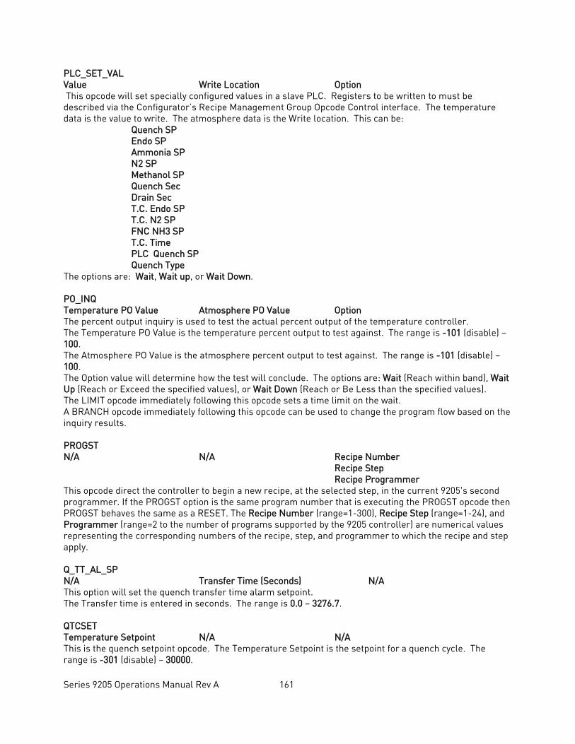
Series 9205 Operations Manual Rev A 161
PLC_SET_VAL Value Write Location Option This opcode will set specially configured values in a slave PLC. Registers to be written to must be described via the Configurator’s Recipe Management Group Opcode Control interface. The temperature data is the value to write. The atmosphere data is the Write location. This can be: Quench SP Endo SP Ammonia SP N2 SP Methanol SP Quench Sec Drain Sec T.C. Endo SP T.C. N2 SP FNC NH3 SP T.C. Time PLC Quench SP Quench Type The options are: Wait, Wait up, or Wait Down. PO_INQ Temperature PO Value Atmosphere PO Value Option The percent output inquiry is used to test the actual percent output of the temperature controller. The Temperature PO Value is the temperature percent output to test against. The range is -101 (disable) – 100. The Atmosphere PO Value is the atmosphere percent output to test against. The range is -101 (disable) – 100. The Option value will determine how the test will conclude. The options are: Wait (Reach within band), Wait Up (Reach or Exceed the specified values), or Wait Down (Reach or Be Less than the specified values). The LIMIT opcode immediately following this opcode sets a time limit on the wait. A BRANCH opcode immediately following this opcode can be used to change the program flow based on the inquiry results. PROGST N/A N/A Recipe Number
Recipe Step Recipe Programmer
This opcode direct the controller to begin a new recipe, at the selected step, in the current 9205's second programmer. If the PROGST option is the same program number that is executing the PROGST opcode then PROGST behaves the same as a RESET. The Recipe Number (range=1-300), Recipe Step (range=1-24), and Programmer (range=2 to the number of programs supported by the 9205 controller) are numerical values representing the corresponding numbers of the recipe, step, and programmer to which the recipe and step apply. Q_TT_AL_SP N/A Transfer Time (Seconds) N/A This option will set the quench transfer time alarm setpoint. The Transfer time is entered in seconds. The range is 0.0 – 3276.7. QTCSET Temperature Setpoint N/A N/A This is the quench setpoint opcode. The Temperature Setpoint is the setpoint for a quench cycle. The range is -301 (disable) – 30000.
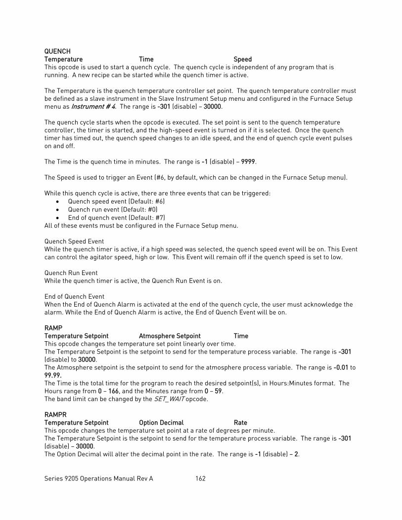
Series 9205 Operations Manual Rev A 162
QUENCH Temperature Time Speed This opcode is used to start a quench cycle. The quench cycle is independent of any program that is running. A new recipe can be started while the quench timer is active. The Temperature is the quench temperature controller set point. The quench temperature controller must be defined as a slave instrument in the Slave Instrument Setup menu and configured in the Furnace Setup menu as Instrument # 4. The range is -301 (disable) – 30000. The quench cycle starts when the opcode is executed. The set point is sent to the quench temperature controller, the timer is started, and the high-speed event is turned on if it is selected. Once the quench timer has timed out, the quench speed changes to an idle speed, and the end of quench cycle event pulses on and off. The Time is the quench time in minutes. The range is -1 (disable) – 9999. The Speed is used to trigger an Event (#6, by default, which can be changed in the Furnace Setup menu). While this quench cycle is active, there are three events that can be triggered:
• Quench speed event (Default: #6) • Quench run event (Default: #0) • End of quench event (Default: #7)
All of these events must be configured in the Furnace Setup menu. Quench Speed Event While the quench timer is active, if a high speed was selected, the quench speed event will be on. This Event can control the agitator speed, high or low. This Event will remain off if the quench speed is set to low. Quench Run Event While the quench timer is active, the Quench Run Event is on. End of Quench Event When the End of Quench Alarm is activated at the end of the quench cycle, the user must acknowledge the alarm. While the End of Quench Alarm is active, the End of Quench Event will be on. RAMP Temperature Setpoint Atmosphere Setpoint Time This opcode changes the temperature set point linearly over time. The Temperature Setpoint is the setpoint to send for the temperature process variable. The range is -301 (disable) to 30000. The Atmosphere setpoint is the setpoint to send for the atmosphere process variable. The range is -0.01 to 99.99. The Time is the total time for the program to reach the desired setpoint(s), in Hours:Minutes format. The Hours range from 0 – 166, and the Minutes range from 0 – 59. The band limit can be changed by the SET_WAIT opcode. RAMPR Temperature Setpoint Option Decimal Rate This opcode changes the temperature set point at a rate of degrees per minute. The Temperature Setpoint is the setpoint to send for the temperature process variable. The range is -301 (disable) – 30000. The Option Decimal will alter the decimal point in the rate. The range is -1 (disable) – 2.
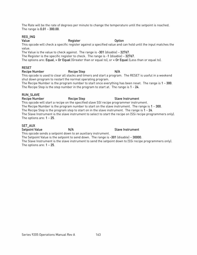
Series 9205 Operations Manual Rev A 163
The Rate will be the rate of degrees per minute to change the temperature until the setpoint is reached. The range is 0.01 – 300.00. REG_INQ Value Register Option This opcode will check a specific register against a specified value and can hold until the input matches the value. The Value is the value to check against. The range is -301 (disable) – 32767. The Register is the specific register to check. The range is -1 (disable) – 32767. The options are: Equal, > Or Equal (Greater than or equal to), or < Or Equal (Less than or equal to). RESET Recipe Number Recipe Step N/A This opcode is used to clear all stacks and timers and start a program. The RESET is useful in a weekend shut down program to restart the normal operating program. The Recipe Number is the program number to start once everything has been reset. The range is 1 – 300. The Recipe Step is the step number in the program to start at. The range is 1 – 24. RUN_SLAVE Recipe Number Recipe Step Slave Instrument This opcode will start a recipe on the specified slave SSI recipe programmer instrument. The Recipe Number is the program number to start on the slave instrument. The range is 1 – 300. The Recipe Step is the program step to start on in the slave instrument. The range is 1 – 24. The Slave Instrument is the slave instrument to select to start the recipe on (SSi recipe programmers only). The options are: 1 – 25. SET_AUX Setpoint Value N/A Slave Instrument This opcode sends a setpoint down to an auxiliary instrument. The Setpoint Value is the setpoint to send down. The range is -301 (disable) – 30000. The Slave Instrument is the slave instrument to send the setpoint down to (SSi recipe programmers only). The options are: 1 – 25.
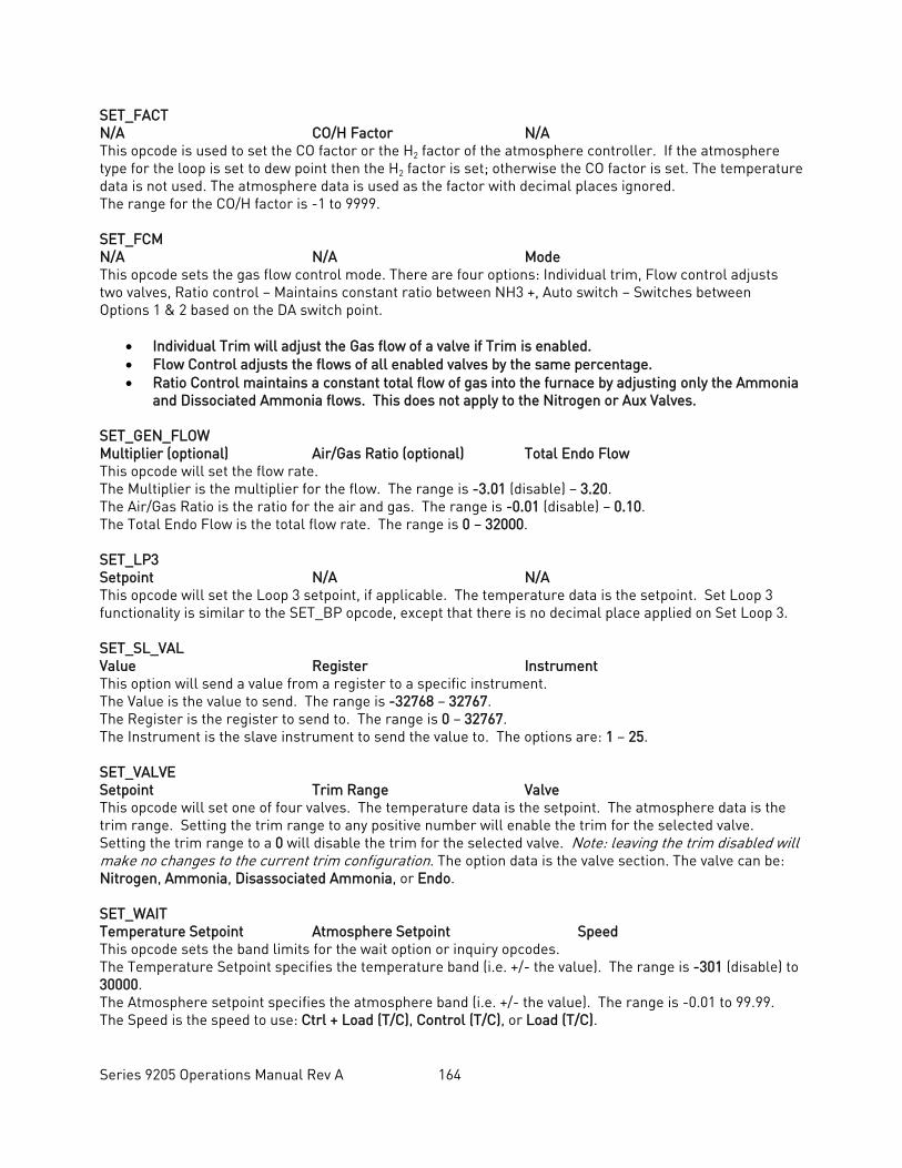
Series 9205 Operations Manual Rev A 164
SET_FACT N/A CO/H Factor N/A This opcode is used to set the CO factor or the H2 factor of the atmosphere controller. If the atmosphere type for the loop is set to dew point then the H2 factor is set; otherwise the CO factor is set. The temperature data is not used. The atmosphere data is used as the factor with decimal places ignored. The range for the CO/H factor is -1 to 9999. SET_FCM N/A N/A Mode This opcode sets the gas flow control mode. There are four options: Individual trim, Flow control adjusts two valves, Ratio control – Maintains constant ratio between NH3 +, Auto switch – Switches between Options 1 & 2 based on the DA switch point.
• Individual Trim will adjust the Gas flow of a valve if Trim is enabled. • Flow Control adjusts the flows of all enabled valves by the same percentage. • Ratio Control maintains a constant total flow of gas into the furnace by adjusting only the Ammonia
and Dissociated Ammonia flows. This does not apply to the Nitrogen or Aux Valves. SET_GEN_FLOW Multiplier (optional) Air/Gas Ratio (optional) Total Endo Flow This opcode will set the flow rate. The Multiplier is the multiplier for the flow. The range is -3.01 (disable) – 3.20. The Air/Gas Ratio is the ratio for the air and gas. The range is -0.01 (disable) – 0.10. The Total Endo Flow is the total flow rate. The range is 0 – 32000. SET_LP3 Setpoint N/A N/A This opcode will set the Loop 3 setpoint, if applicable. The temperature data is the setpoint. Set Loop 3 functionality is similar to the SET_BP opcode, except that there is no decimal place applied on Set Loop 3. SET_SL_VAL Value Register Instrument This option will send a value from a register to a specific instrument. The Value is the value to send. The range is -32768 – 32767. The Register is the register to send to. The range is 0 – 32767. The Instrument is the slave instrument to send the value to. The options are: 1 – 25. SET_VALVE Setpoint Trim Range Valve This opcode will set one of four valves. The temperature data is the setpoint. The atmosphere data is the trim range. Setting the trim range to any positive number will enable the trim for the selected valve. Setting the trim range to a 0 will disable the trim for the selected valve. Note: leaving the trim disabled will make no changes to the current trim configuration. The option data is the valve section. The valve can be: Nitrogen, Ammonia, Disassociated Ammonia, or Endo. SET_WAIT Temperature Setpoint Atmosphere Setpoint Speed This opcode sets the band limits for the wait option or inquiry opcodes. The Temperature Setpoint specifies the temperature band (i.e. +/- the value). The range is -301 (disable) to 30000. The Atmosphere setpoint specifies the atmosphere band (i.e. +/- the value). The range is -0.01 to 99.99. The Speed is the speed to use: Ctrl + Load (T/C), Control (T/C), or Load (T/C).
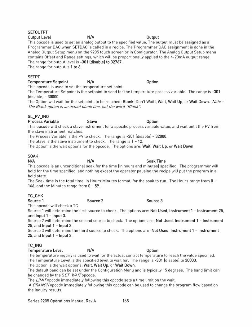
Series 9205 Operations Manual Rev A 165
SETOUTPT Output Level N/A Output This opcode is used to set an analog output to the specified value. The output must be assigned as a Programmer DAC when SETDAC is called in a recipe. The Programmer DAC assignment is done in the Analog Output Setup menu on the 9205 touch screen or in Configurator. The Analog Output Setup menu contains Offset and Range settings, which will be proportionally applied to the 4-20mA output range. The range for output level is -301 (disable) to 32767. The range for output is 1 to 6. SETPT Temperature Setpoint N/A Option This opcode is used to set the temperature set point. The Temperature Setpoint is the setpoint to send for the temperature process variable. The range is -301 (disable) – 30000. The Option will wait for the setpoints to be reached: Blank (Don’t Wait), Wait, Wait Up, or Wait Down. Note – The Blank option is an actual blank line, not the word “Blank”. SL_PV_INQ Process Variable Slave Option This opcode will check a slave instrument for a specific process variable value, and wait until the PV from the slave instrument matches. The Process Variable is the PV to check. The range is -301 (disable) – 32000. The Slave is the slave instrument to check. The range is 1 – 12. The Option is the wait options for the opcode. The options are: Wait, Wait Up, or Wait Down. SOAK N/A N/A Soak Time This opcode is an unconditional soak for the time (in hours and minutes) specified. The programmer will hold for the time specified, and nothing except the operator pausing the recipe will put the program in a hold state. The Soak time is the total time, in Hours:Minutes format, for the soak to run. The Hours range from 0 – 166, and the Minutes range from 0 – 59. TC_CHK Source 1 Source 2 Source 3 This opcode will check a TC Source 1 will determine the first source to check. The options are: Not Used, Instrument 1 – Instrument 25, and Input 1 – Input 3. Source 2 will determine the second source to check. The options are: Not Used, Instrument 1 – Instrument 25, and Input 1 – Input 3. Source 3 will determine the third source to check. The options are: Not Used, Instrument 1 – Instrument 25, and Input 1 – Input 3. TC_INQ Temperature Level N/A Option The temperature inquiry is used to wait for the actual control temperature to reach the value specified. The Temperature Level is the specified level to wait for. The range is -301 (disable) to 30000. The Option is the wait options: Wait, Wait Up, or Wait Down. The default band can be set under the Configuration Menu and is typically 15 degrees. The band limit can be changed by the SET_WAIT opcode. The LIMIT opcode immediately following this opcode sets a time limit on the wait. A BRANCH opcode immediately following this opcode can be used to change the program flow based on the inquiry results.
Series 9205 Operations Manual Rev A 166
timeEVT N/A Delay Time Option This opcode will turn ON or OFF a specified event for the specified amount of time. The Delay Time is the time in seconds. The range is: 0 – 500. The Option is the event to turn ON or OFF. The options are: Event 0 ON or OFF – Event 31 ON or OFF. TOD_INQ N/A N/A Time This opcode is a time of day inquiry that would be used to start a process or subroutine at a specific hour and minute. The Time is the time to check, in Hours:Minutes format. The Hours range from 0 – 23, and the Minutes range from 0 – 59. TZ_INQ Temperature Level N/A Option The zone temperature inquiry is used to wait for the actual control zone temperature to reach the value specified. The Temperature Level is the specified level to wait for. The range is -301 (disable) – 30000. The Option is the wait options: Wait, Wait Up, or Wait Down. The default band can be set under the Configuration Menu and is typically 15 degrees. The band limit can be changed by the SET_WAIT opcode. The LIMIT opcode immediately following this opcode sets a time limit on the wait. A BRANCH opcode immediately following this opcode can be used to change the program flow based on the inquiry results. This opcode is identical to the TC_INQ opcode, except that it will deal with zones. Z_SETPT Temperature Setpoint Atmosphere Setpoint Option This opcode is used to set the temperature or atmosphere set point for a zone. The Temperature Setpoint is the setpoint to send for the temperature process variable. The range is -301 (disable) to 30000. The atmosphere Setpoint is the setpoint to send for the atmosphere process variable. The range is -0.01 to 99.99. The Option will wait for the setpoints to be reached: Blank (Don’t Wait), Wait, Wait Up, or Wait Down. Note – The Blank option is an actual blank line, not the word “Blank”. ZONE_OFF Temperature Value Atmosphere Value Zone The Zone Offset opcode is used to set a temperature or atmosphere offset to be added to the set point sent to a specific zone. The same loop (furnace) can have different offsets for each zone. The zones must be defined in the zone configuration. For example, a pit furnace has three zones: top, middle, and bottom. The zones could be defined as: • top = zone 1 • middle = zone 2 • bottom = zone 3
If the ZONE_OFF opcode is used in a program with Temperature Value = 50 and Zone = 1 and a setpoint of 1700, then:
• A set point of 1750 would be sent to the top zone (Zone 1) • A set point of 1700 would be sent to the middle zone (Zone 2) • A set point of 1700 would be sent to the bottom zone (Zone 3)

Series 9205 Operations Manual Rev A 167
The Temperature value is the offset value to send to the specified zone. The range is -301 (disable) – 30000. The Atmosphere value is the offset value to send to the specified zone. The range is -0.01 to 99.99. The Zone is the specific zone to send the offsets to. The options are: Zone 1 – Zone 5.
Series 9205 Operations Manual Rev A 168
Warranty Limited Warranty for Super Systems Products: The Limited Warranty applies to new Super Systems Inc. (SSI) products purchased direct from SSI or from an authorized SSI dealer by the original purchaser for normal use. SSI warrants that a covered product is free from defects in materials and workmanship, with the exceptions stated below. The limited warranty does not cover damage resulting from commercial use, misuse, accident, modification or alteration to hardware or software, tampering, unsuitable physical or operating environment beyond product specifications, improper maintenance, or failure caused by a product for which SSI is not responsible. There is no warranty of uninterrupted or error-free operation. There is no warranty for loss of data—you must regularly back up the data stored on your product to a separate storage product. There is no warranty for product with removed or altered identification labels. SSI DOES NOT PROVIDE ANY OTHER WARRANTIES OF ANY KIND, INCLUDING, BUT NOT LIMITED TO, THE IMPLIED WARRANTIES OR CONDITIONS OF MERCHANTABILITY AND FITNESS FOR A PARTICULAR PURPOSE. SOME JURISDICTIONS DO NOT ALLOW THE LIMITATION OF IMPLIED WARRANTIES, SO THIS LIMITATION MAY NOT APPLY TO YOU. SSI is not responsible for returning to you product which is not covered by this limited warranty. If you are having trouble with a product, before seeking limited warranty service, first follow the troubleshooting procedures that SSI or your authorized SSI dealer provides. SSI will replace the PRODUCT with a functionally equivalent replacement product, transportation prepaid after PRODUCT has been returned to SSI for testing and evaluation. SSI may replace your product with a product that was previously used, repaired and tested to meet SSI specifications. You receive title to the replaced product at delivery to carrier at SSI shipping point. You are responsible for importation of the replaced product, if applicable. SSI will not return the original product to you; therefore, you are responsible for moving data to another media before returning to SSI, if applicable. Data Recovery is not covered under this warranty and is not part of the warranty returns process. SSI warrants that the replaced products are covered for the remainder of the original product warranty or 90 days, whichever is greater.
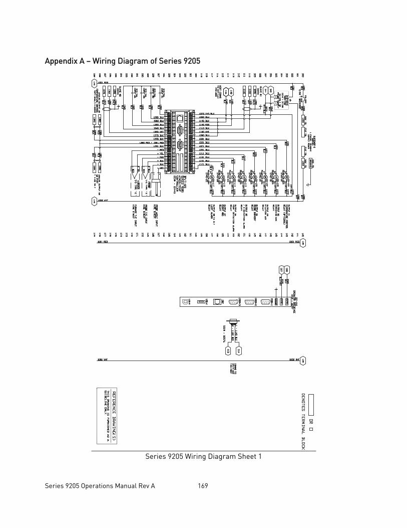
Series 9205 Operations Manual Rev A 169
Appendix A – Wiring Diagram of Series 9205
Series 9205 Wiring Diagram Sheet 1
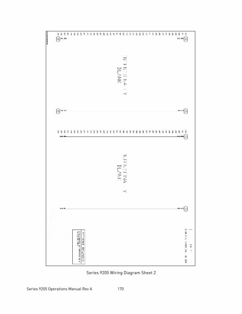
Series 9205 Operations Manual Rev A 170
Series 9205 Wiring Diagram Sheet 2
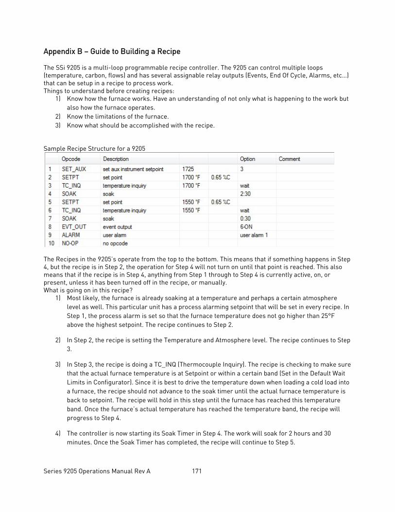
Series 9205 Operations Manual Rev A 171
Appendix B – Guide to Building a Recipe The SSi 9205 is a multi-loop programmable recipe controller. The 9205 can control multiple loops (temperature, carbon, flows) and has several assignable relay outputs (Events, End Of Cycle, Alarms, etc…) that can be setup in a recipe to process work. Things to understand before creating recipes:
1) Know how the furnace works. Have an understanding of not only what is happening to the work but also how the furnace operates.
2) Know the limitations of the furnace. 3) Know what should be accomplished with the recipe.
Sample Recipe Structure for a 9205
The Recipes in the 9205’s operate from the top to the bottom. This means that if something happens in Step 4, but the recipe is in Step 2, the operation for Step 4 will not turn on until that point is reached. This also means that if the recipe is in Step 4, anything from Step 1 through to Step 4 is currently active, on, or present, unless it has been turned off in the recipe, or manually. What is going on in this recipe?
1) Most likely, the furnace is already soaking at a temperature and perhaps a certain atmosphere level as well. This particular unit has a process alarming setpoint that will be set in every recipe. In Step 1, the process alarm is set so that the furnace temperature does not go higher than 25°F above the highest setpoint. The recipe continues to Step 2.
2) In Step 2, the recipe is setting the Temperature and Atmosphere level. The recipe continues to Step 3.
3) In Step 3, the recipe is doing a TC_INQ (Thermocouple Inquiry). The recipe is checking to make sure that the actual furnace temperature is at Setpoint or within a certain band (Set in the Default Wait Limits in Configurator). Since it is best to drive the temperature down when loading a cold load into a furnace, the recipe should not advance to the soak timer until the actual furnace temperature is back to setpoint. The recipe will hold in this step until the furnace has reached this temperature band. Once the furnace’s actual temperature has reached the temperature band, the recipe will progress to Step 4.
4) The controller is now starting its Soak Timer in Step 4. The work will soak for 2 hours and 30 minutes. Once the Soak Timer has completed, the recipe will continue to Step 5.
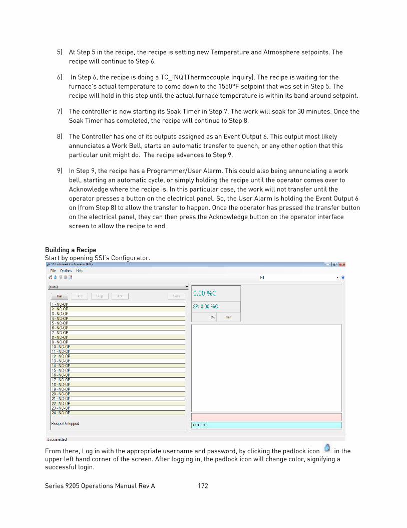
Series 9205 Operations Manual Rev A 172
5) At Step 5 in the recipe, the recipe is setting new Temperature and Atmosphere setpoints. The recipe will continue to Step 6.
6) In Step 6, the recipe is doing a TC_INQ (Thermocouple Inquiry). The recipe is waiting for the furnace’s actual temperature to come down to the 1550°F setpoint that was set in Step 5. The recipe will hold in this step until the actual furnace temperature is within its band around setpoint.
7) The controller is now starting its Soak Timer in Step 7. The work will soak for 30 minutes. Once the Soak Timer has completed, the recipe will continue to Step 8.
8) The Controller has one of its outputs assigned as an Event Output 6. This output most likely annunciates a Work Bell, starts an automatic transfer to quench, or any other option that this particular unit might do. The recipe advances to Step 9.
9) In Step 9, the recipe has a Programmer/User Alarm. This could also being annunciating a work bell, starting an automatic cycle, or simply holding the recipe until the operator comes over to Acknowledge where the recipe is. In this particular case, the work will not transfer until the operator presses a button on the electrical panel. So, the User Alarm is holding the Event Output 6 on (from Step 8) to allow the transfer to happen. Once the operator has pressed the transfer button on the electrical panel, they can then press the Acknowledge button on the operator interface screen to allow the recipe to end.
Building a Recipe Start by opening SSI’s Configurator.
From there, Log in with the appropriate username and password, by clicking the padlock icon in the upper left hand corner of the screen. After logging in, the padlock icon will change color, signifying a successful login.
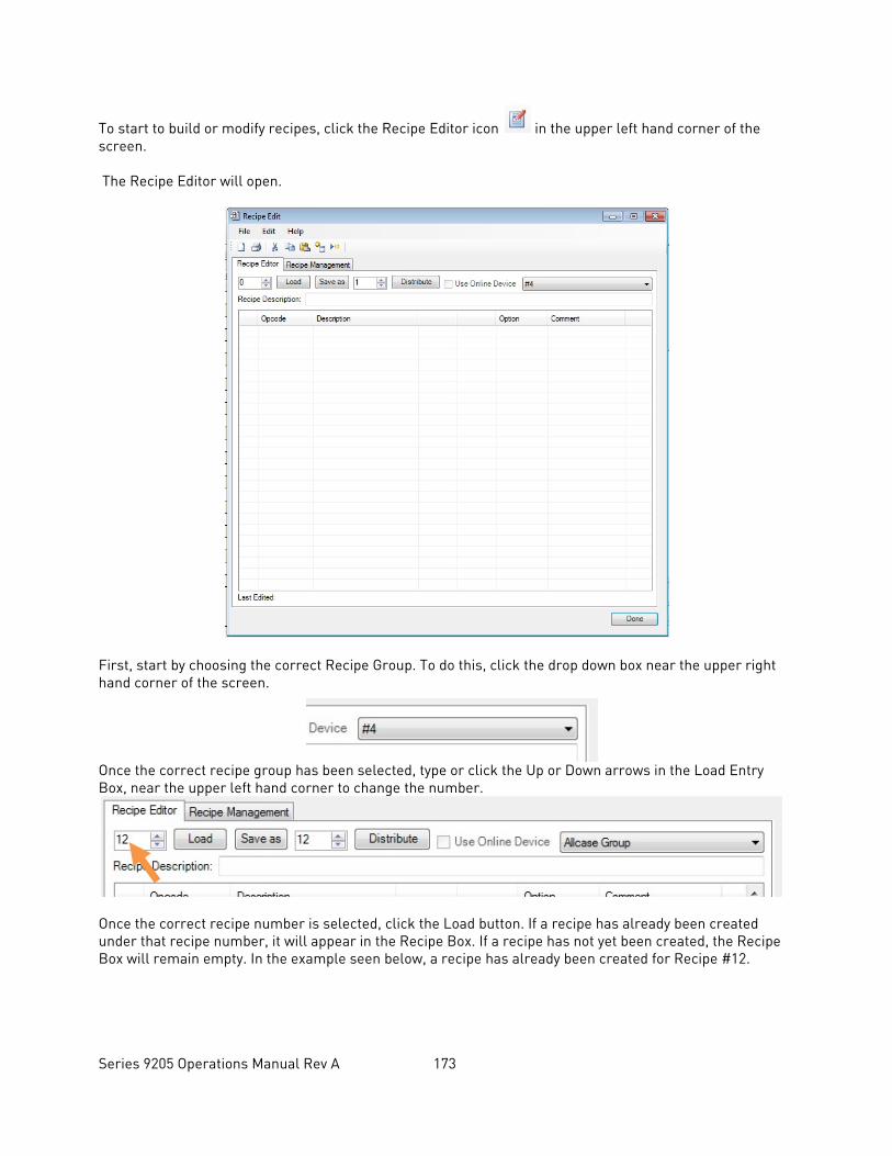
Series 9205 Operations Manual Rev A 173
To start to build or modify recipes, click the Recipe Editor icon in the upper left hand corner of the screen. The Recipe Editor will open.
First, start by choosing the correct Recipe Group. To do this, click the drop down box near the upper right hand corner of the screen. Once the correct recipe group has been selected, type or click the Up or Down arrows in the Load Entry Box, near the upper left hand corner to change the number.
Once the correct recipe number is selected, click the Load button. If a recipe has already been created under that recipe number, it will appear in the Recipe Box. If a recipe has not yet been created, the Recipe Box will remain empty. In the example seen below, a recipe has already been created for Recipe #12.
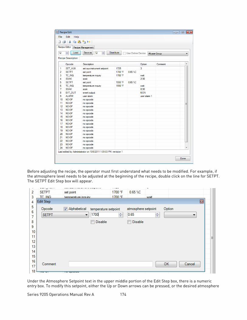
Series 9205 Operations Manual Rev A 174
Before adjusting the recipe, the operator must first understand what needs to be modified. For example, if the atmosphere level needs to be adjusted at the beginning of the recipe, double click on the line for SETPT. The SETPT Edit Step box will appear.
Under the Atmosphere Setpoint text in the upper middle portion of the Edit Step box, there is a numeric entry box. To modify this setpoint, either the Up or Down arrows can be pressed, or the desired atmosphere
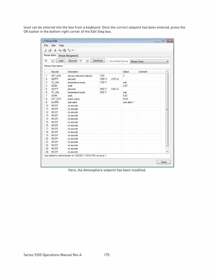
Series 9205 Operations Manual Rev A 175
level can be entered into the box from a keyboard. Once the correct setpoint has been entered, press the OK button in the bottom right corner of the Edit Step box.
Here, the Atmosphere setpoint has been modified.
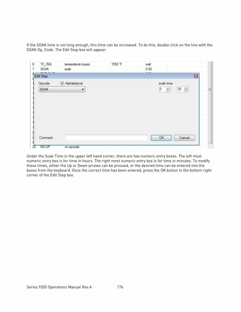
Series 9205 Operations Manual Rev A 176
If the SOAK time is not long enough, this time can be increased. To do this, double click on the line with the SOAK Op_Code. The Edit Step box will appear.
Under the Soak Time in the upper left hand corner, there are two numeric entry boxes. The left most numeric entry box is for time in hours. The right most numeric entry box is for time in minutes. To modify these times, either the Up or Down arrows can be pressed, or the desired time can be entered into the boxes from the keyboard. Once the correct time has been entered, press the OK button in the bottom right corner of the Edit Step box.
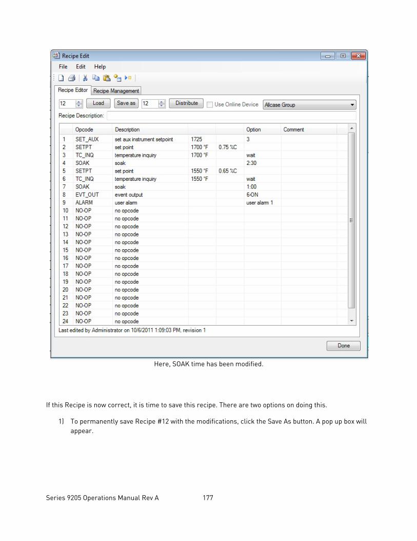
Series 9205 Operations Manual Rev A 177
Here, SOAK time has been modified.
If this Recipe is now correct, it is time to save this recipe. There are two options on doing this.
1) To permanently save Recipe #12 with the modifications, click the Save As button. A pop up box will appear.
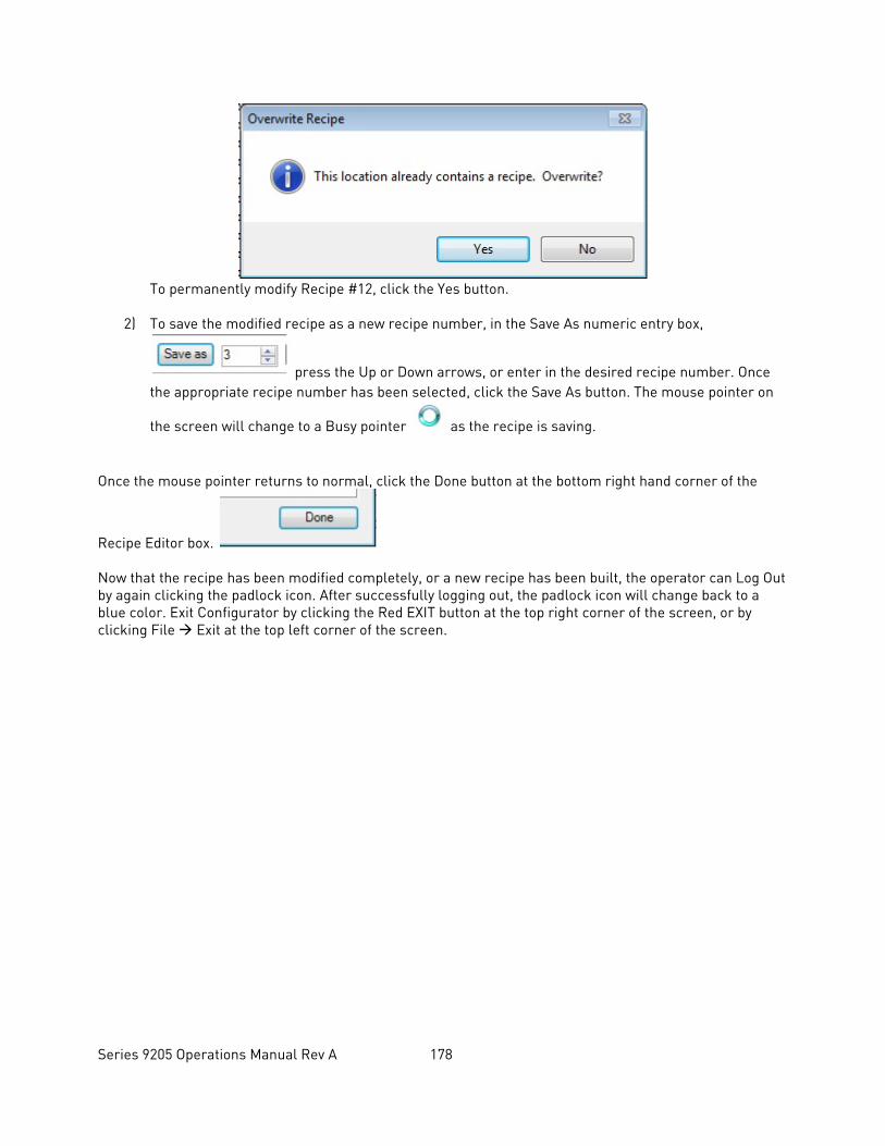
Series 9205 Operations Manual Rev A 178
To permanently modify Recipe #12, click the Yes button.
2) To save the modified recipe as a new recipe number, in the Save As numeric entry box,
press the Up or Down arrows, or enter in the desired recipe number. Once the appropriate recipe number has been selected, click the Save As button. The mouse pointer on
the screen will change to a Busy pointer as the recipe is saving.
Once the mouse pointer returns to normal, click the Done button at the bottom right hand corner of the
Recipe Editor box. Now that the recipe has been modified completely, or a new recipe has been built, the operator can Log Out by again clicking the padlock icon. After successfully logging out, the padlock icon will change back to a blue color. Exit Configurator by clicking the Red EXIT button at the top right corner of the screen, or by clicking File Exit at the top left corner of the screen.
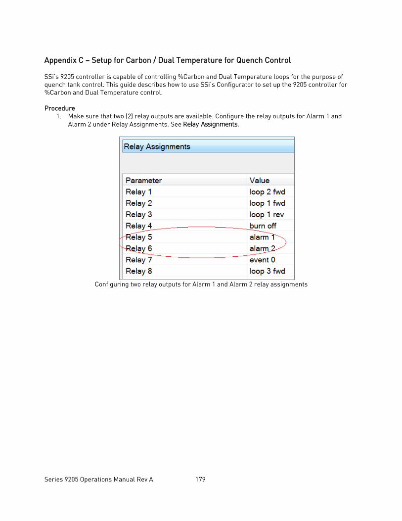
Series 9205 Operations Manual Rev A 179
Appendix C – Setup for Carbon / Dual Temperature for Quench Control SSi’s 9205 controller is capable of controlling %Carbon and Dual Temperature loops for the purpose of quench tank control. This guide describes how to use SSi’s Configurator to set up the 9205 controller for %Carbon and Dual Temperature control. Procedure
1. Make sure that two (2) relay outputs are available. Configure the relay outputs for Alarm 1 and Alarm 2 under Relay Assignments. See Relay Assignments.
Configuring two relay outputs for Alarm 1 and Alarm 2 relay assignments
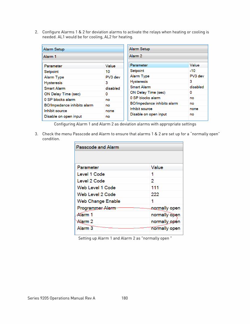
Series 9205 Operations Manual Rev A 180
2. Configure Alarms 1 & 2 for deviation alarms to activate the relays when heating or cooling is needed. AL1 would be for cooling, AL2 for heating.
Configuring Alarm 1 and Alarm 2 as deviation alarms with appropriate settings
3. Check the menu Passcode and Alarm to ensure that alarms 1 & 2 are set up for a “normally open”
condition.
Setting up Alarm 1 and Alarm 2 as "normally open "
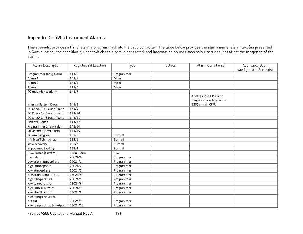
xSeries 9205 Operations Manual Rev A 181
Appendix D – 9205 Instrument Alarms This appendix provides a list of alarms programmed into the 9205 controller. The table below provides the alarm name, alarm text (as presented in Configurator), the condition(s) under which the alarm is generated, and information on user-accessible settings that affect the triggering of the alarm.
Alarm Description Register/Bit Location Type Values Alarm Condition(s) Applicable User-Configurable Setting(s)
Programmer (any) alarm 141/0 Programmer Alarm 1 141/1 Main Alarm 2 141/2 Main Alarm 3 141/3 Main TC redundancy alarm 141/7
Internal System Error 141/8
Analog input CPU is no longer responding to the 9205's main CPU.
TC Check 1->2 out of band 141/9 TC Check 1->3 out of band 141/10 TC Check 2->3 out of band 141/11 End of Quench 141/12 Programmer 2 (any) alarm 141/14 Slave coms (any) alarm 141/15 TC rise too great 163/0 Burnoff mV insufficient drop 163/1 Burnoff slow recovery 163/2 Burnoff impedance too high 163/3 Burnoff PLC Alarms (custom) 2980 - 2989 PLC user alarm 25024/0 Programmer deviation, atmosphere 25024/1 Programmer high atmosphere 25024/2 Programmer low atmosphere 25024/3 Programmer deviation, temperature 25024/4 Programmer high temperature 25024/5 Programmer low temperature 25024/6 Programmer high atm % output 25024/7 Programmer low atm % output 25024/8 Programmer high temperature % output 25024/9 Programmer
low temperature % output 25024/10 Programmer
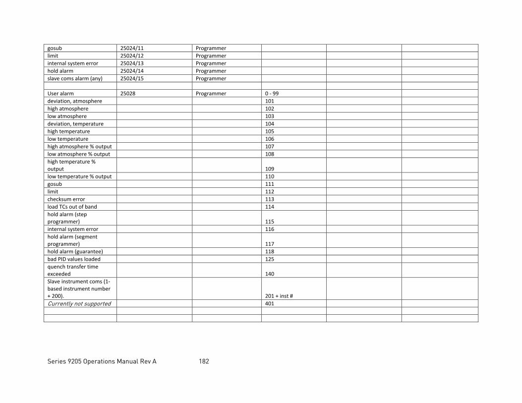
Series 9205 Operations Manual Rev A 182
gosub 25024/11 Programmer limit 25024/12 Programmer internal system error 25024/13 Programmer hold alarm 25024/14 Programmer slave coms alarm (any) 25024/15 Programmer User alarm 25028 Programmer 0 - 99 deviation, atmosphere 101 high atmosphere 102 low atmosphere 103 deviation, temperature 104 high temperature 105 low temperature 106 high atmosphere % output 107 low atmosphere % output 108 high temperature % output
109
low temperature % output 110 gosub 111 limit 112 checksum error 113 load TCs out of band 114 hold alarm (step programmer)
115
internal system error 116 hold alarm (segment programmer)
117
hold alarm (guarantee) 118 bad PID values loaded 125 quench transfer time exceeded
140
Slave instrument coms (1-based instrument number + 200).
201 + inst #
Currently not supported 401
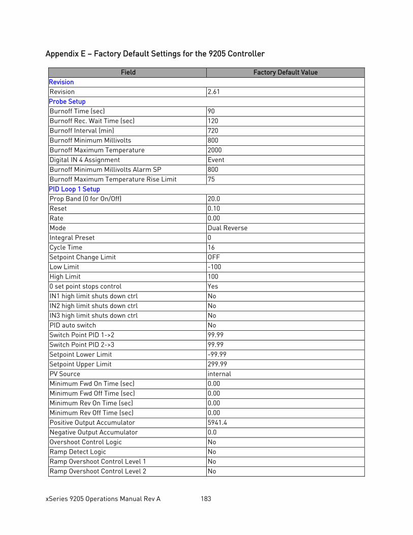
xSeries 9205 Operations Manual Rev A 183
Appendix E – Factory Default Settings for the 9205 Controller
Field Factory Default Value Revision Revision 2.61 Probe Setup Burnoff Time (sec) 90 Burnoff Rec. Wait Time (sec) 120 Burnoff Interval (min) 720 Burnoff Minimum Millivolts 800 Burnoff Maximum Temperature 2000 Digital IN 4 Assignment Event Burnoff Minimum Millivolts Alarm SP 800 Burnoff Maximum Temperature Rise Limit 75 PID Loop 1 Setup Prop Band (0 for On/Off) 20.0 Reset 0.10 Rate 0.00 Mode Dual Reverse Integral Preset 0 Cycle Time 16 Setpoint Change Limit OFF Low Limit -100 High Limit 100 0 set point stops control Yes IN1 high limit shuts down ctrl No IN2 high limit shuts down ctrl No IN3 high limit shuts down ctrl No PID auto switch No Switch Point PID 1->2 99.99 Switch Point PID 2->3 99.99 Setpoint Lower Limit -99.99 Setpoint Upper Limit 299.99 PV Source internal Minimum Fwd On Time (sec) 0.00 Minimum Fwd Off Time (sec) 0.00 Minimum Rev On Time (sec) 0.00 Minimum Rev Off Time (sec) 0.00 Positive Output Accumulator 5941.4 Negative Output Accumulator 0.0 Overshoot Control Logic No Ramp Detect Logic No Ramp Overshoot Control Level 1 No Ramp Overshoot Control Level 2 No
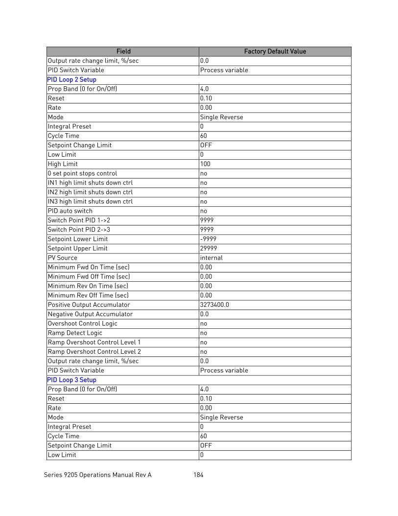
Series 9205 Operations Manual Rev A 184
Field Factory Default Value Output rate change limit, %/sec 0.0 PID Switch Variable Process variable PID Loop 2 Setup Prop Band (0 for On/Off) 4.0 Reset 0.10 Rate 0.00 Mode Single Reverse Integral Preset 0 Cycle Time 60 Setpoint Change Limit OFF Low Limit 0 High Limit 100 0 set point stops control no IN1 high limit shuts down ctrl no IN2 high limit shuts down ctrl no IN3 high limit shuts down ctrl no PID auto switch no Switch Point PID 1->2 9999 Switch Point PID 2->3 9999 Setpoint Lower Limit -9999 Setpoint Upper Limit 29999 PV Source internal Minimum Fwd On Time (sec) 0.00 Minimum Fwd Off Time (sec) 0.00 Minimum Rev On Time (sec) 0.00 Minimum Rev Off Time (sec) 0.00 Positive Output Accumulator 3273400.0 Negative Output Accumulator 0.0 Overshoot Control Logic no Ramp Detect Logic no Ramp Overshoot Control Level 1 no Ramp Overshoot Control Level 2 no Output rate change limit, %/sec 0.0 PID Switch Variable Process variable PID Loop 3 Setup Prop Band (0 for On/Off) 4.0 Reset 0.10 Rate 0.00 Mode Single Reverse Integral Preset 0 Cycle Time 60 Setpoint Change Limit OFF Low Limit 0
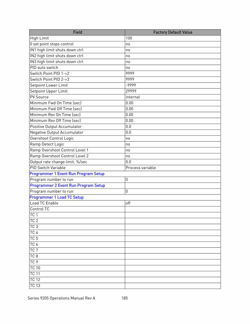
Series 9205 Operations Manual Rev A 185
Field Factory Default Value High Limit 100 0 set point stops control no IN1 high limit shuts down ctrl no IN2 high limit shuts down ctrl no IN3 high limit shuts down ctrl no PID auto switch no Switch Point PID 1->2 9999 Switch Point PID 2->3 9999 Setpoint Lower Limit -9999 Setpoint Upper Limit 29999 PV Source internal Minimum Fwd On Time (sec) 0.00 Minimum Fwd Off Time (sec) 0.00 Minimum Rev On Time (sec) 0.00 Minimum Rev Off Time (sec) 0.00 Positive Output Accumulator 0.0 Negative Output Accumulator 0.0 Overshoot Control Logic no Ramp Detect Logic no Ramp Overshoot Control Level 1 no Ramp Overshoot Control Level 2 no Output rate change limit, %/sec 0.0 PID Switch Variable Process variable Programmer 1 Event Run Program Setup Program number to run 0 Programmer 2 Event Run Program Setup Program number to run 0 Programmer 1 Load TC Setup Load TC Enable off Control TC TC 1 TC 2 TC 3 TC 4 TC 5 TC 6 TC 7 TC 8 TC 9 TC 10 TC 11 TC 12 TC 13
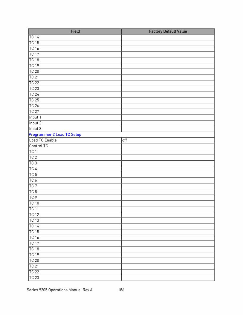
Series 9205 Operations Manual Rev A 186
Field Factory Default Value TC 14 TC 15 TC 16 TC 17 TC 18 TC 19 TC 20 TC 21 TC 22 TC 23 TC 24 TC 25 TC 26 TC 27 Input 1 Input 2 Input 3 Programmer 2 Load TC Setup Load TC Enable off Control TC TC 1 TC 2 TC 3 TC 4 TC 5 TC 6 TC 7 TC 8 TC 9 TC 10 TC 11 TC 12 TC 13 TC 14 TC 15 TC 16 TC 17 TC 18 TC 19 TC 20 TC 21 TC 22 TC 23
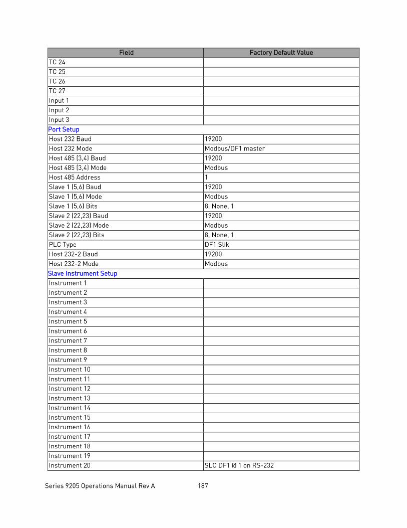
Series 9205 Operations Manual Rev A 187
Field Factory Default Value TC 24 TC 25 TC 26 TC 27 Input 1 Input 2 Input 3 Port Setup Host 232 Baud 19200 Host 232 Mode Modbus/DF1 master Host 485 (3,4) Baud 19200 Host 485 (3,4) Mode Modbus Host 485 Address 1 Slave 1 (5,6) Baud 19200 Slave 1 (5,6) Mode Modbus Slave 1 (5,6) Bits 8, None, 1 Slave 2 (22,23) Baud 19200 Slave 2 (22,23) Mode Modbus Slave 2 (22,23) Bits 8, None, 1 PLC Type DF1 Slik Host 232-2 Baud 19200 Host 232-2 Mode Modbus Slave Instrument Setup Instrument 1 Instrument 2 Instrument 3 Instrument 4 Instrument 5 Instrument 6 Instrument 7 Instrument 8 Instrument 9 Instrument 10 Instrument 11 Instrument 12 Instrument 13 Instrument 14 Instrument 15 Instrument 16 Instrument 17 Instrument 18 Instrument 19 Instrument 20 SLC DF1 @ 1 on RS-232
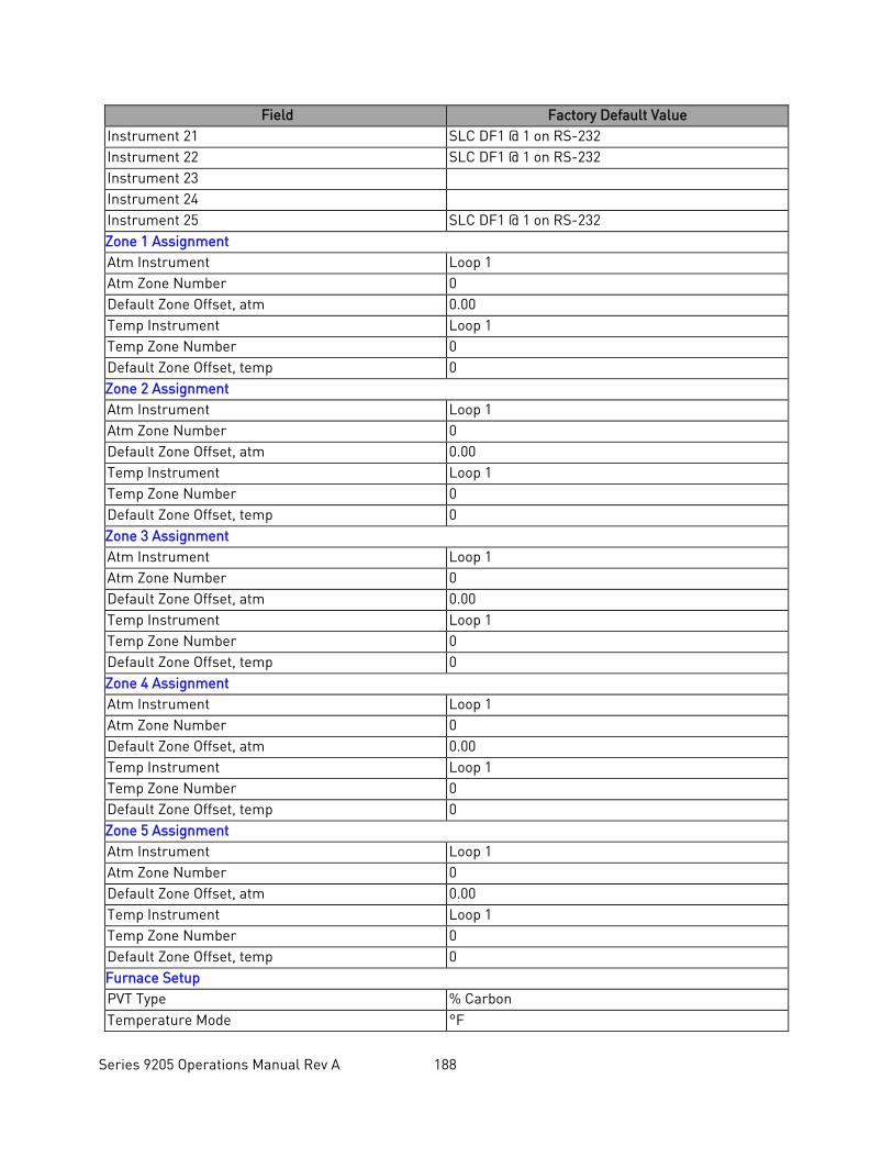
Series 9205 Operations Manual Rev A 188
Field Factory Default Value Instrument 21 SLC DF1 @ 1 on RS-232 Instrument 22 SLC DF1 @ 1 on RS-232 Instrument 23 Instrument 24 Instrument 25 SLC DF1 @ 1 on RS-232 Zone 1 Assignment Atm Instrument Loop 1 Atm Zone Number 0 Default Zone Offset, atm 0.00 Temp Instrument Loop 1 Temp Zone Number 0 Default Zone Offset, temp 0 Zone 2 Assignment Atm Instrument Loop 1 Atm Zone Number 0 Default Zone Offset, atm 0.00 Temp Instrument Loop 1 Temp Zone Number 0 Default Zone Offset, temp 0 Zone 3 Assignment Atm Instrument Loop 1 Atm Zone Number 0 Default Zone Offset, atm 0.00 Temp Instrument Loop 1 Temp Zone Number 0 Default Zone Offset, temp 0 Zone 4 Assignment Atm Instrument Loop 1 Atm Zone Number 0 Default Zone Offset, atm 0.00 Temp Instrument Loop 1 Temp Zone Number 0 Default Zone Offset, temp 0 Zone 5 Assignment Atm Instrument Loop 1 Atm Zone Number 0 Default Zone Offset, atm 0.00 Temp Instrument Loop 1 Temp Zone Number 0 Default Zone Offset, temp 0 Furnace Setup PVT Type % Carbon Temperature Mode °F
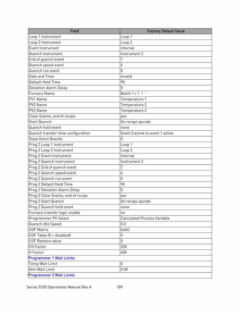
Series 9205 Operations Manual Rev A 189
Field Factory Default Value Loop 1 Instrument Loop 1 Loop 2 Instrument Loop 2 Event Instrument internal Quench Instrument Instrument 2 End of quench event 7 Quench speed event 6 Quench run event 0 Date and Time invalid Default Hold Time 90 Deviation Alarm Delay 0 Furnace Name Batch 1 r 1 ! ' PV1 Name Temperature 1 PV2 Name Temperature 2 PV3 Name Temperature 3 Clear Events, end of recipe yes Start Quench On recipe opcode Quench hold event none Quench transfer time configuration Event 0 active to event 1 active Slave Event Boards 0 Prog 2 Loop 1 Instrument Loop 1 Prog 2 Loop 2 Instrument Loop 2 Prog 2 Event Instrument internal Prog 2 Quench Instrument Instrument 2 Prog 2 End of quench event 7 Prog 2 Quench speed event 6 Prog 2 Quench run event 0 Prog 2 Default Hold Time 90 Prog 2 Deviation Alarm Delay 0 Prog 2 Clear Events, end of recipe yes Prog 2 Start Quench On recipe opcode Prog 2 Quench hold event none Furnace transfer logic enable no Programmer PV Select Calculated Process Variable Quench Idle Speed 0.0 COF Matrix (edit) COF Table (0 = disabled) 0 COF Restore value 0 CO Factor 200 H Factor 400 Programmer 1 Wait Limits Temp Wait Limit 0 Atm Wait Limit 0.00 Programmer 2 Wait Limits
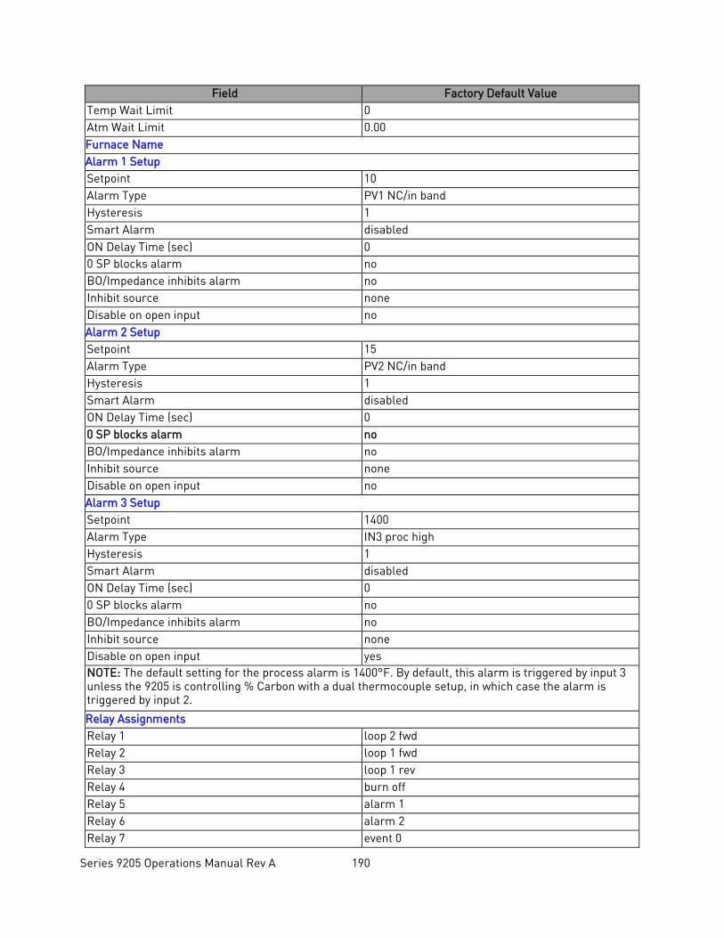
Series 9205 Operations Manual Rev A 190
Field Factory Default Value Temp Wait Limit 0 Atm Wait Limit 0.00 Furnace Name Alarm 1 Setup Setpoint 10 Alarm Type PV1 NC/in band Hysteresis 1 Smart Alarm disabled ON Delay Time (sec) 0 0 SP blocks alarm no BO/Impedance inhibits alarm no Inhibit source none Disable on open input no Alarm 2 Setup Setpoint 15 Alarm Type PV2 NC/in band Hysteresis 1 Smart Alarm disabled ON Delay Time (sec) 0 0 SP blocks alarm no BO/Impedance inhibits alarm no Inhibit source none Disable on open input no Alarm 3 Setup Setpoint 1400 Alarm Type IN3 proc high Hysteresis 1 Smart Alarm disabled ON Delay Time (sec) 0 0 SP blocks alarm no BO/Impedance inhibits alarm no Inhibit source none Disable on open input yes NOTE: The default setting for the process alarm is 1400°F. By default, this alarm is triggered by input 3 unless the 9205 is controlling % Carbon with a dual thermocouple setup, in which case the alarm is triggered by input 2.
Relay Assignments Relay 1 loop 2 fwd Relay 2 loop 1 fwd Relay 3 loop 1 rev Relay 4 burn off Relay 5 alarm 1 Relay 6 alarm 2 Relay 7 event 0
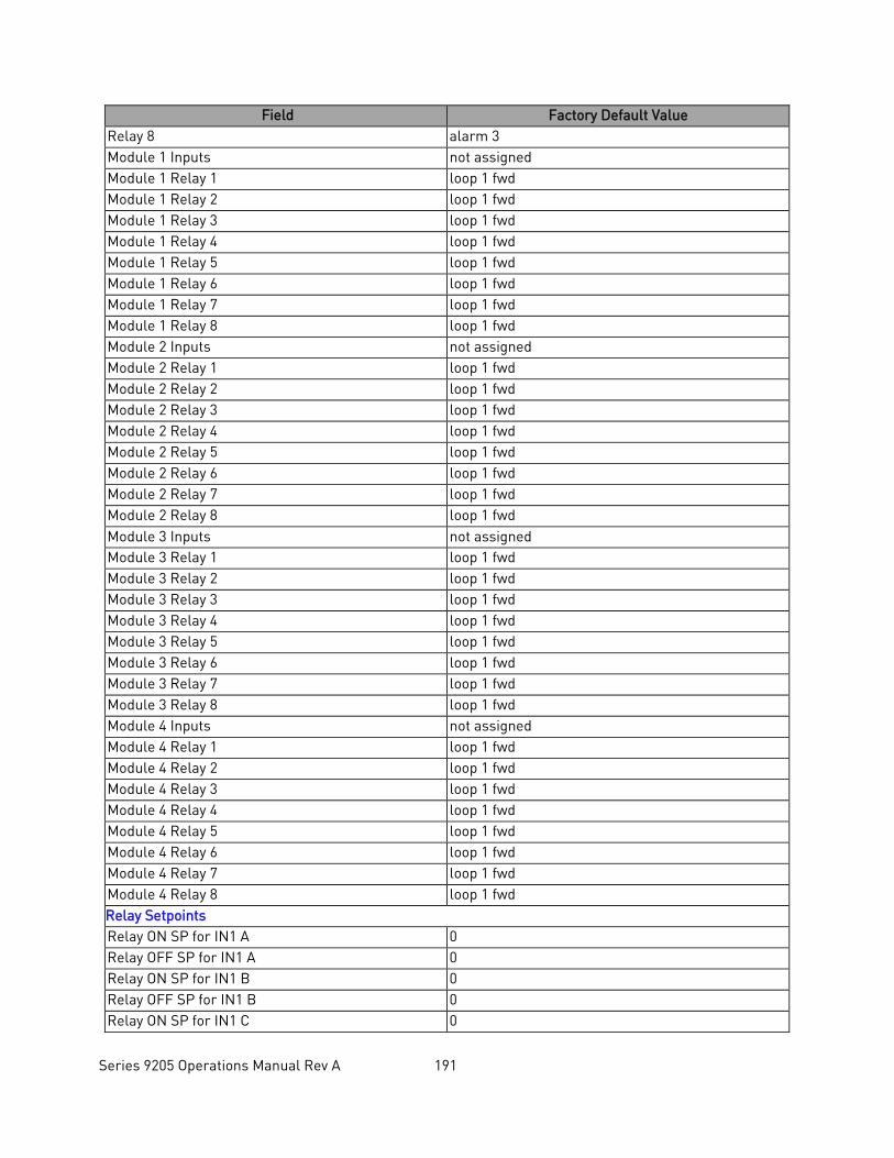
Series 9205 Operations Manual Rev A 191
Field Factory Default Value Relay 8 alarm 3 Module 1 Inputs not assigned Module 1 Relay 1 loop 1 fwd Module 1 Relay 2 loop 1 fwd Module 1 Relay 3 loop 1 fwd Module 1 Relay 4 loop 1 fwd Module 1 Relay 5 loop 1 fwd Module 1 Relay 6 loop 1 fwd Module 1 Relay 7 loop 1 fwd Module 1 Relay 8 loop 1 fwd Module 2 Inputs not assigned Module 2 Relay 1 loop 1 fwd Module 2 Relay 2 loop 1 fwd Module 2 Relay 3 loop 1 fwd Module 2 Relay 4 loop 1 fwd Module 2 Relay 5 loop 1 fwd Module 2 Relay 6 loop 1 fwd Module 2 Relay 7 loop 1 fwd Module 2 Relay 8 loop 1 fwd Module 3 Inputs not assigned Module 3 Relay 1 loop 1 fwd Module 3 Relay 2 loop 1 fwd Module 3 Relay 3 loop 1 fwd Module 3 Relay 4 loop 1 fwd Module 3 Relay 5 loop 1 fwd Module 3 Relay 6 loop 1 fwd Module 3 Relay 7 loop 1 fwd Module 3 Relay 8 loop 1 fwd Module 4 Inputs not assigned Module 4 Relay 1 loop 1 fwd Module 4 Relay 2 loop 1 fwd Module 4 Relay 3 loop 1 fwd Module 4 Relay 4 loop 1 fwd Module 4 Relay 5 loop 1 fwd Module 4 Relay 6 loop 1 fwd Module 4 Relay 7 loop 1 fwd Module 4 Relay 8 loop 1 fwd Relay Setpoints Relay ON SP for IN1 A 0 Relay OFF SP for IN1 A 0 Relay ON SP for IN1 B 0 Relay OFF SP for IN1 B 0 Relay ON SP for IN1 C 0
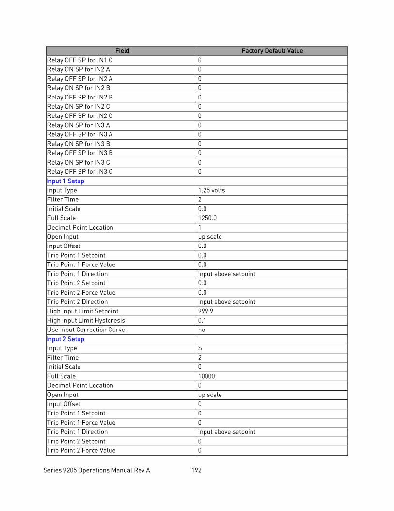
Series 9205 Operations Manual Rev A 192
Field Factory Default Value Relay OFF SP for IN1 C 0 Relay ON SP for IN2 A 0 Relay OFF SP for IN2 A 0 Relay ON SP for IN2 B 0 Relay OFF SP for IN2 B 0 Relay ON SP for IN2 C 0 Relay OFF SP for IN2 C 0 Relay ON SP for IN3 A 0 Relay OFF SP for IN3 A 0 Relay ON SP for IN3 B 0 Relay OFF SP for IN3 B 0 Relay ON SP for IN3 C 0 Relay OFF SP for IN3 C 0 Input 1 Setup Input Type 1.25 volts Filter Time 2 Initial Scale 0.0 Full Scale 1250.0 Decimal Point Location 1 Open Input up scale Input Offset 0.0 Trip Point 1 Setpoint 0.0 Trip Point 1 Force Value 0.0 Trip Point 1 Direction input above setpoint Trip Point 2 Setpoint 0.0 Trip Point 2 Force Value 0.0 Trip Point 2 Direction input above setpoint High Input Limit Setpoint 999.9 High Input Limit Hysteresis 0.1 Use Input Correction Curve no Input 2 Setup Input Type S Filter Time 2 Initial Scale 0 Full Scale 10000 Decimal Point Location 0 Open Input up scale Input Offset 0 Trip Point 1 Setpoint 0 Trip Point 1 Force Value 0 Trip Point 1 Direction input above setpoint Trip Point 2 Setpoint 0 Trip Point 2 Force Value 0
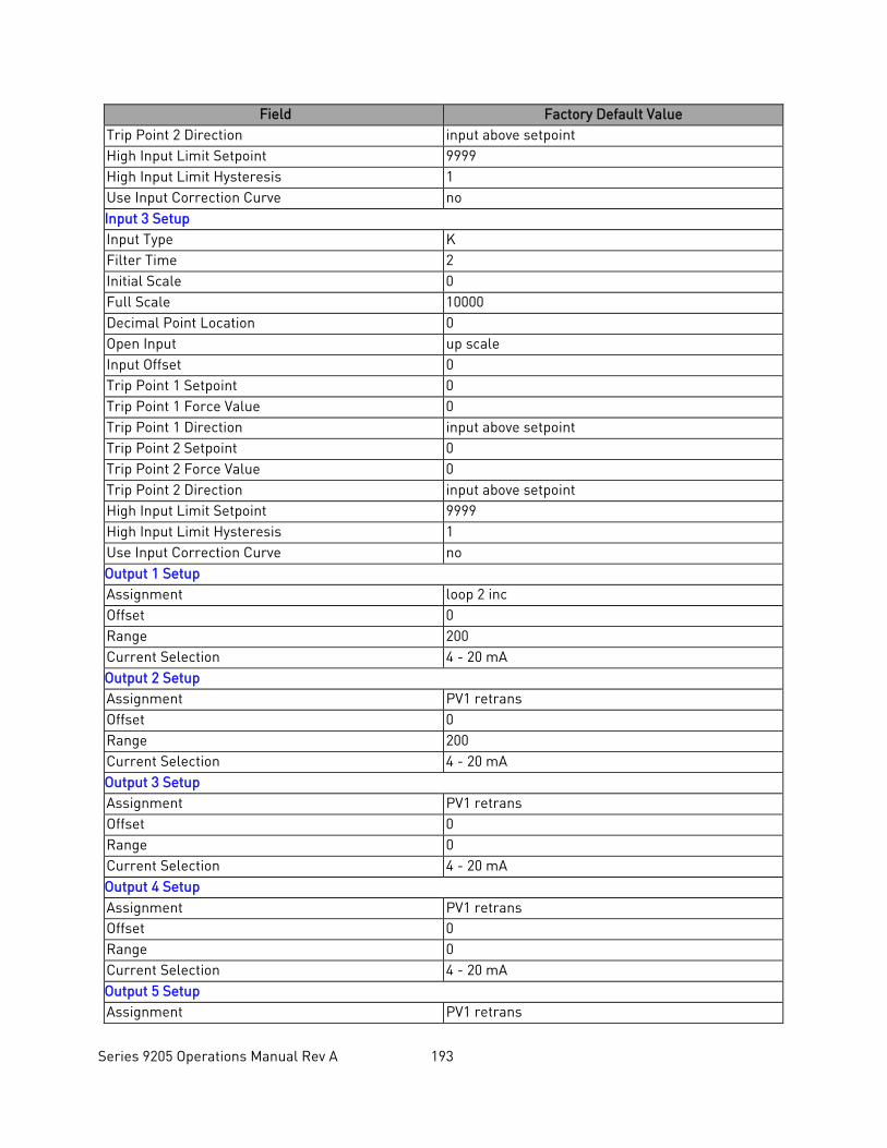
Series 9205 Operations Manual Rev A 193
Field Factory Default Value Trip Point 2 Direction input above setpoint High Input Limit Setpoint 9999 High Input Limit Hysteresis 1 Use Input Correction Curve no Input 3 Setup Input Type K Filter Time 2 Initial Scale 0 Full Scale 10000 Decimal Point Location 0 Open Input up scale Input Offset 0 Trip Point 1 Setpoint 0 Trip Point 1 Force Value 0 Trip Point 1 Direction input above setpoint Trip Point 2 Setpoint 0 Trip Point 2 Force Value 0 Trip Point 2 Direction input above setpoint High Input Limit Setpoint 9999 High Input Limit Hysteresis 1 Use Input Correction Curve no Output 1 Setup Assignment loop 2 inc Offset 0 Range 200 Current Selection 4 - 20 mA Output 2 Setup Assignment PV1 retrans Offset 0 Range 200 Current Selection 4 - 20 mA Output 3 Setup Assignment PV1 retrans Offset 0 Range 0 Current Selection 4 - 20 mA Output 4 Setup Assignment PV1 retrans Offset 0 Range 0 Current Selection 4 - 20 mA Output 5 Setup Assignment PV1 retrans
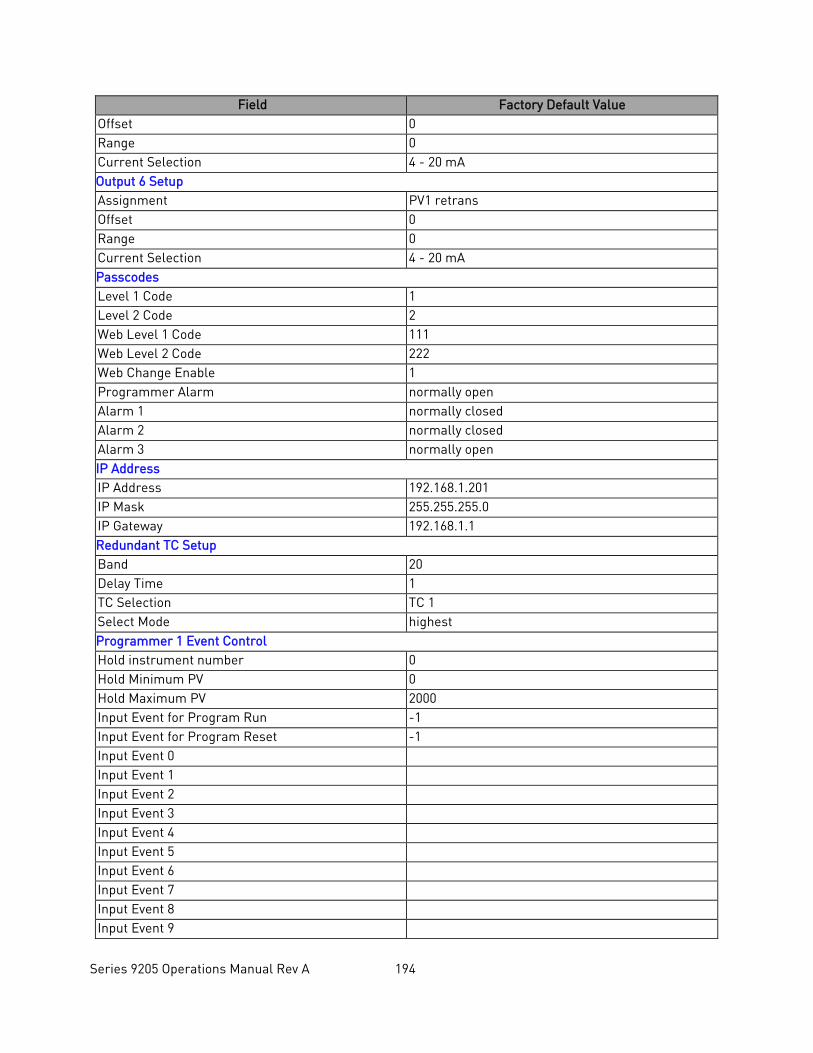
Series 9205 Operations Manual Rev A 194
Field Factory Default Value Offset 0 Range 0 Current Selection 4 - 20 mA Output 6 Setup Assignment PV1 retrans Offset 0 Range 0 Current Selection 4 - 20 mA Passcodes Level 1 Code 1 Level 2 Code 2 Web Level 1 Code 111 Web Level 2 Code 222 Web Change Enable 1 Programmer Alarm normally open Alarm 1 normally closed Alarm 2 normally closed Alarm 3 normally open IP Address IP Address 192.168.1.201 IP Mask 255.255.255.0 IP Gateway 192.168.1.1 Redundant TC Setup Band 20 Delay Time 1 TC Selection TC 1 Select Mode highest Programmer 1 Event Control Hold instrument number 0 Hold Minimum PV 0 Hold Maximum PV 2000 Input Event for Program Run -1 Input Event for Program Reset -1 Input Event 0 Input Event 1 Input Event 2 Input Event 3 Input Event 4 Input Event 5 Input Event 6 Input Event 7 Input Event 8 Input Event 9
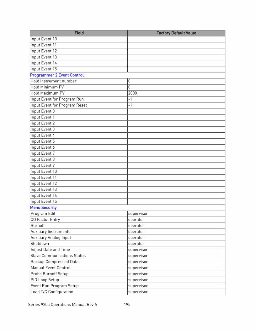
Series 9205 Operations Manual Rev A 195
Field Factory Default Value Input Event 10 Input Event 11 Input Event 12 Input Event 13 Input Event 14 Input Event 15 Programmer 2 Event Control Hold instrument number 0 Hold Minimum PV 0 Hold Maximum PV 2000 Input Event for Program Run -1 Input Event for Program Reset -1 Input Event 0 Input Event 1 Input Event 2 Input Event 3 Input Event 4 Input Event 5 Input Event 6 Input Event 7 Input Event 8 Input Event 9 Input Event 10 Input Event 11 Input Event 12 Input Event 13 Input Event 14 Input Event 15 Menu Security Program Edit supervisor CO Factor Entry operator Burnoff operator Auxiliary Instruments operator Auxiliary Analog Input operator Shutdown operator Adjust Date and Time supervisor Slave Communications Status supervisor Backup Compressed Data supervisor Manual Event Control supervisor Probe Burnoff Setup supervisor PID Loop Setup supervisor Event Run Program Setup supervisor Load T/C Configuration supervisor
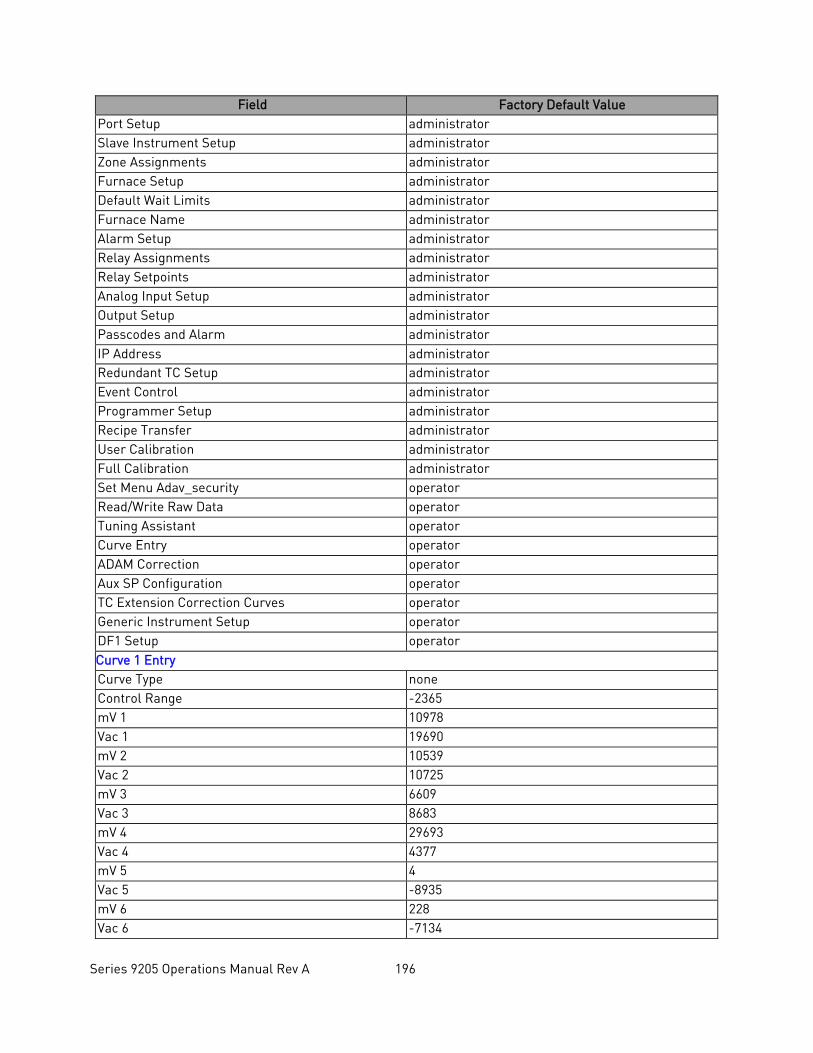
Series 9205 Operations Manual Rev A 196
Field Factory Default Value Port Setup administrator Slave Instrument Setup administrator Zone Assignments administrator Furnace Setup administrator Default Wait Limits administrator Furnace Name administrator Alarm Setup administrator Relay Assignments administrator Relay Setpoints administrator Analog Input Setup administrator Output Setup administrator Passcodes and Alarm administrator IP Address administrator Redundant TC Setup administrator Event Control administrator Programmer Setup administrator Recipe Transfer administrator User Calibration administrator Full Calibration administrator Set Menu Adav_security operator Read/Write Raw Data operator Tuning Assistant operator Curve Entry operator ADAM Correction operator Aux SP Configuration operator TC Extension Correction Curves operator Generic Instrument Setup operator DF1 Setup operator Curve 1 Entry Curve Type none Control Range -2365 mV 1 10978 Vac 1 19690 mV 2 10539 Vac 2 10725 mV 3 6609 Vac 3 8683 mV 4 29693 Vac 4 4377 mV 5 4 Vac 5 -8935 mV 6 228 Vac 6 -7134
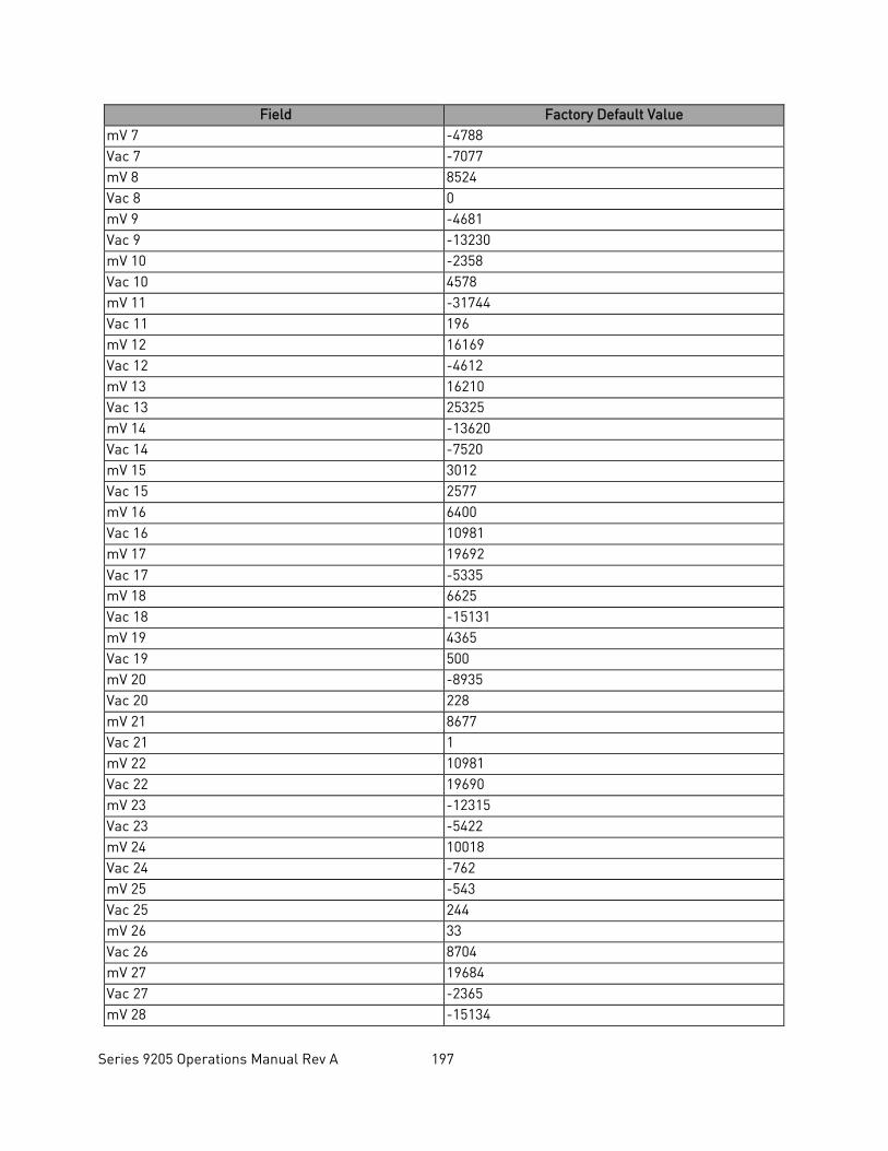
Series 9205 Operations Manual Rev A 197
Field Factory Default Value mV 7 -4788 Vac 7 -7077 mV 8 8524 Vac 8 0 mV 9 -4681 Vac 9 -13230 mV 10 -2358 Vac 10 4578 mV 11 -31744 Vac 11 196 mV 12 16169 Vac 12 -4612 mV 13 16210 Vac 13 25325 mV 14 -13620 Vac 14 -7520 mV 15 3012 Vac 15 2577 mV 16 6400 Vac 16 10981 mV 17 19692 Vac 17 -5335 mV 18 6625 Vac 18 -15131 mV 19 4365 Vac 19 500 mV 20 -8935 Vac 20 228 mV 21 8677 Vac 21 1 mV 22 10981 Vac 22 19690 mV 23 -12315 Vac 23 -5422 mV 24 10018 Vac 24 -762 mV 25 -543 Vac 25 244 mV 26 33 Vac 26 8704 mV 27 19684 Vac 27 -2365 mV 28 -15134
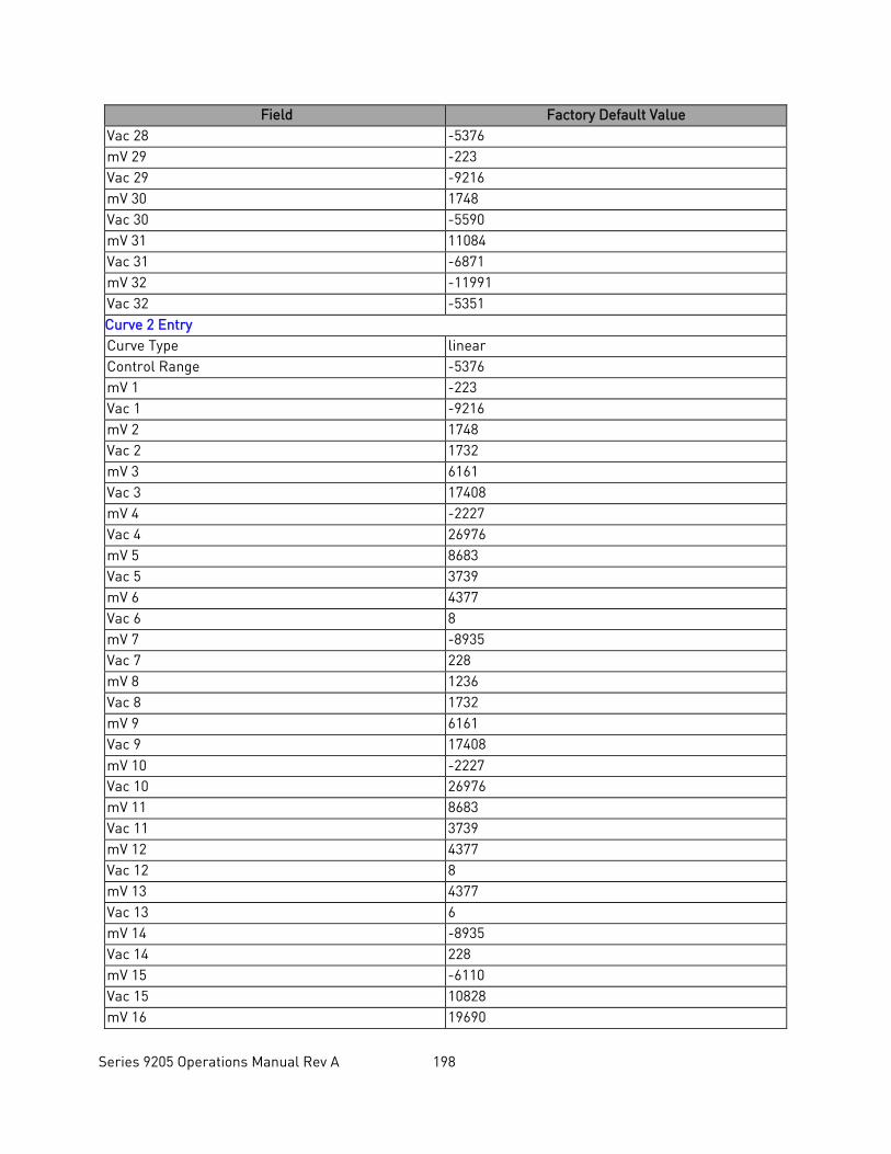
Series 9205 Operations Manual Rev A 198
Field Factory Default Value Vac 28 -5376 mV 29 -223 Vac 29 -9216 mV 30 1748 Vac 30 -5590 mV 31 11084 Vac 31 -6871 mV 32 -11991 Vac 32 -5351 Curve 2 Entry Curve Type linear Control Range -5376 mV 1 -223 Vac 1 -9216 mV 2 1748 Vac 2 1732 mV 3 6161 Vac 3 17408 mV 4 -2227 Vac 4 26976 mV 5 8683 Vac 5 3739 mV 6 4377 Vac 6 8 mV 7 -8935 Vac 7 228 mV 8 1236 Vac 8 1732 mV 9 6161 Vac 9 17408 mV 10 -2227 Vac 10 26976 mV 11 8683 Vac 11 3739 mV 12 4377 Vac 12 8 mV 13 4377 Vac 13 6 mV 14 -8935 Vac 14 228 mV 15 -6110 Vac 15 10828 mV 16 19690
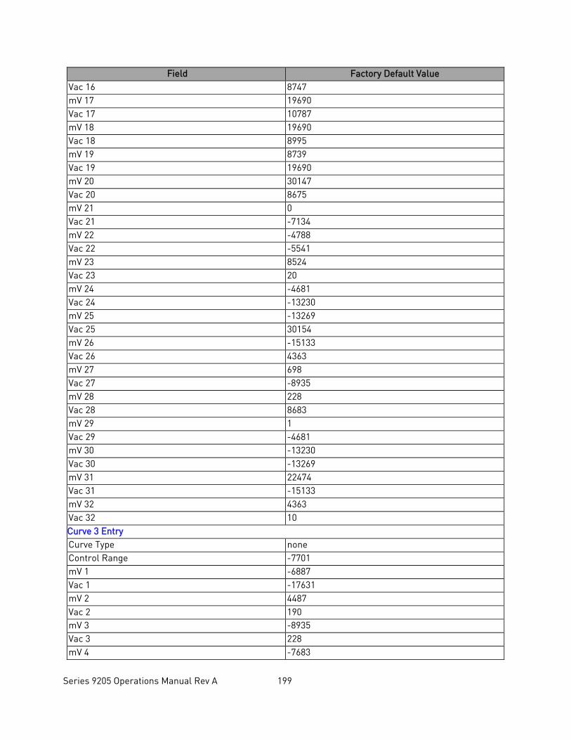
Series 9205 Operations Manual Rev A 199
Field Factory Default Value Vac 16 8747 mV 17 19690 Vac 17 10787 mV 18 19690 Vac 18 8995 mV 19 8739 Vac 19 19690 mV 20 30147 Vac 20 8675 mV 21 0 Vac 21 -7134 mV 22 -4788 Vac 22 -5541 mV 23 8524 Vac 23 20 mV 24 -4681 Vac 24 -13230 mV 25 -13269 Vac 25 30154 mV 26 -15133 Vac 26 4363 mV 27 698 Vac 27 -8935 mV 28 228 Vac 28 8683 mV 29 1 Vac 29 -4681 mV 30 -13230 Vac 30 -13269 mV 31 22474 Vac 31 -15133 mV 32 4363 Vac 32 10 Curve 3 Entry Curve Type none Control Range -7701 mV 1 -6887 Vac 1 -17631 mV 2 4487 Vac 2 190 mV 3 -8935 Vac 3 228 mV 4 -7683
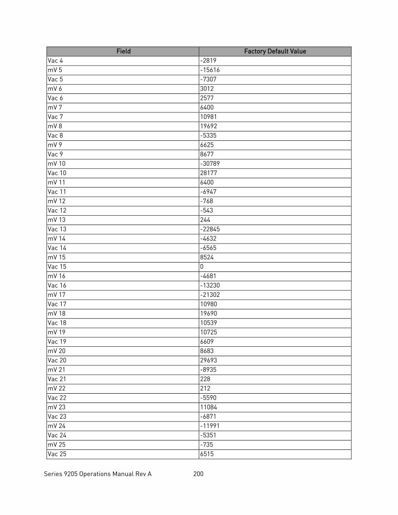
Series 9205 Operations Manual Rev A 200
Field Factory Default Value Vac 4 -2819 mV 5 -15616 Vac 5 -7307 mV 6 3012 Vac 6 2577 mV 7 6400 Vac 7 10981 mV 8 19692 Vac 8 -5335 mV 9 6625 Vac 9 8677 mV 10 -30789 Vac 10 28177 mV 11 6400 Vac 11 -6947 mV 12 -768 Vac 12 -543 mV 13 244 Vac 13 -22845 mV 14 -4632 Vac 14 -6565 mV 15 8524 Vac 15 0 mV 16 -4681 Vac 16 -13230 mV 17 -21302 Vac 17 10980 mV 18 19690 Vac 18 10539 mV 19 10725 Vac 19 6609 mV 20 8683 Vac 20 29693 mV 21 -8935 Vac 21 228 mV 22 212 Vac 22 -5590 mV 23 11084 Vac 23 -6871 mV 24 -11991 Vac 24 -5351 mV 25 -735 Vac 25 6515
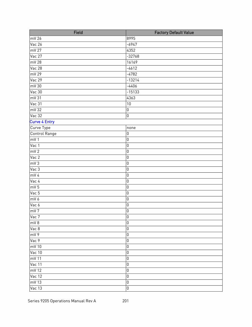
Series 9205 Operations Manual Rev A 201
Field Factory Default Value mV 26 8995 Vac 26 -6947 mV 27 4352 Vac 27 -32768 mV 28 16169 Vac 28 -4612 mV 29 -4782 Vac 29 -13214 mV 30 -4406 Vac 30 -15133 mV 31 4363 Vac 31 10 mV 32 0 Vac 32 0 Curve 4 Entry Curve Type none Control Range 0 mV 1 0 Vac 1 0 mV 2 0 Vac 2 0 mV 3 0 Vac 3 0 mV 4 0 Vac 4 0 mV 5 0 Vac 5 0 mV 6 0 Vac 6 0 mV 7 0 Vac 7 0 mV 8 0 Vac 8 0 mV 9 0 Vac 9 0 mV 10 0 Vac 10 0 mV 11 0 Vac 11 0 mV 12 0 Vac 12 0 mV 13 0 Vac 13 0
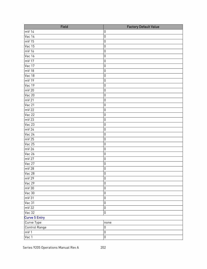
Series 9205 Operations Manual Rev A 202
Field Factory Default Value mV 14 0 Vac 14 0 mV 15 0 Vac 15 0 mV 16 0 Vac 16 0 mV 17 0 Vac 17 0 mV 18 0 Vac 18 0 mV 19 0 Vac 19 0 mV 20 0 Vac 20 0 mV 21 0 Vac 21 0 mV 22 0 Vac 22 0 mV 23 0 Vac 23 0 mV 24 0 Vac 24 0 mV 25 0 Vac 25 0 mV 26 0 Vac 26 0 mV 27 0 Vac 27 0 mV 28 0 Vac 28 0 mV 29 0 Vac 29 0 mV 30 0 Vac 30 0 mV 31 0 Vac 31 0 mV 32 0 Vac 32 0 Curve 5 Entry Curve Type none Control Range 0 mV 1 0 Vac 1 0
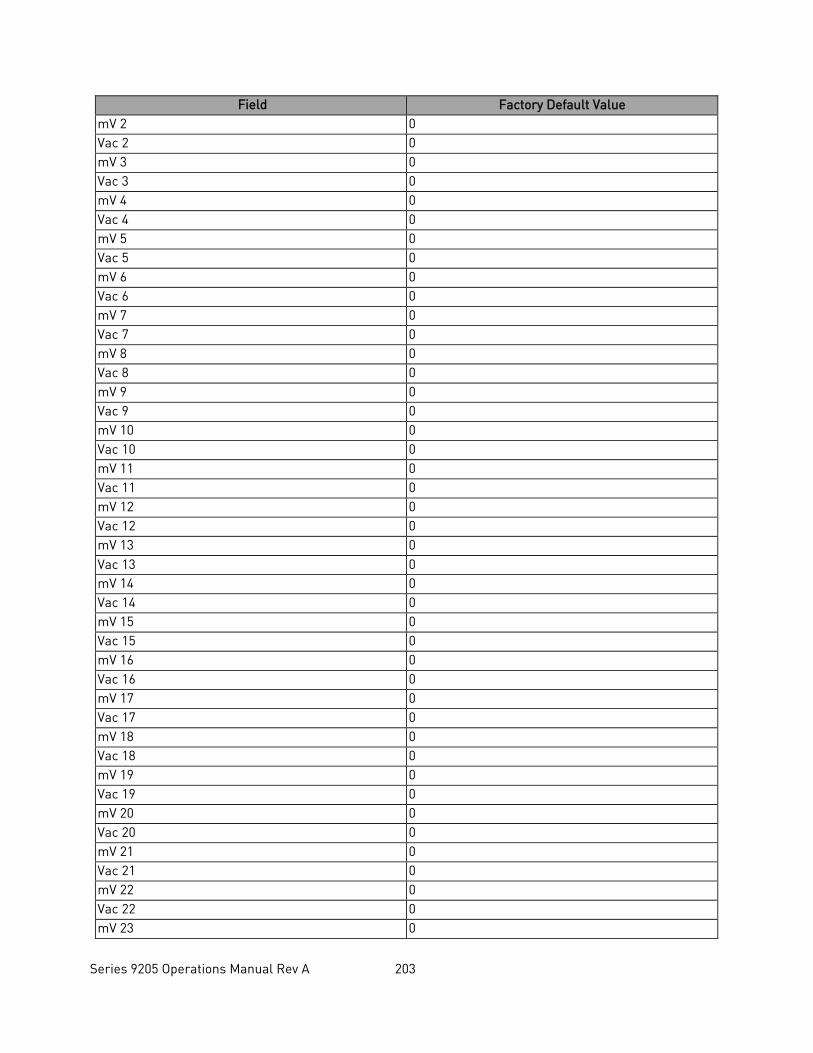
Series 9205 Operations Manual Rev A 203
Field Factory Default Value mV 2 0 Vac 2 0 mV 3 0 Vac 3 0 mV 4 0 Vac 4 0 mV 5 0 Vac 5 0 mV 6 0 Vac 6 0 mV 7 0 Vac 7 0 mV 8 0 Vac 8 0 mV 9 0 Vac 9 0 mV 10 0 Vac 10 0 mV 11 0 Vac 11 0 mV 12 0 Vac 12 0 mV 13 0 Vac 13 0 mV 14 0 Vac 14 0 mV 15 0 Vac 15 0 mV 16 0 Vac 16 0 mV 17 0 Vac 17 0 mV 18 0 Vac 18 0 mV 19 0 Vac 19 0 mV 20 0 Vac 20 0 mV 21 0 Vac 21 0 mV 22 0 Vac 22 0 mV 23 0
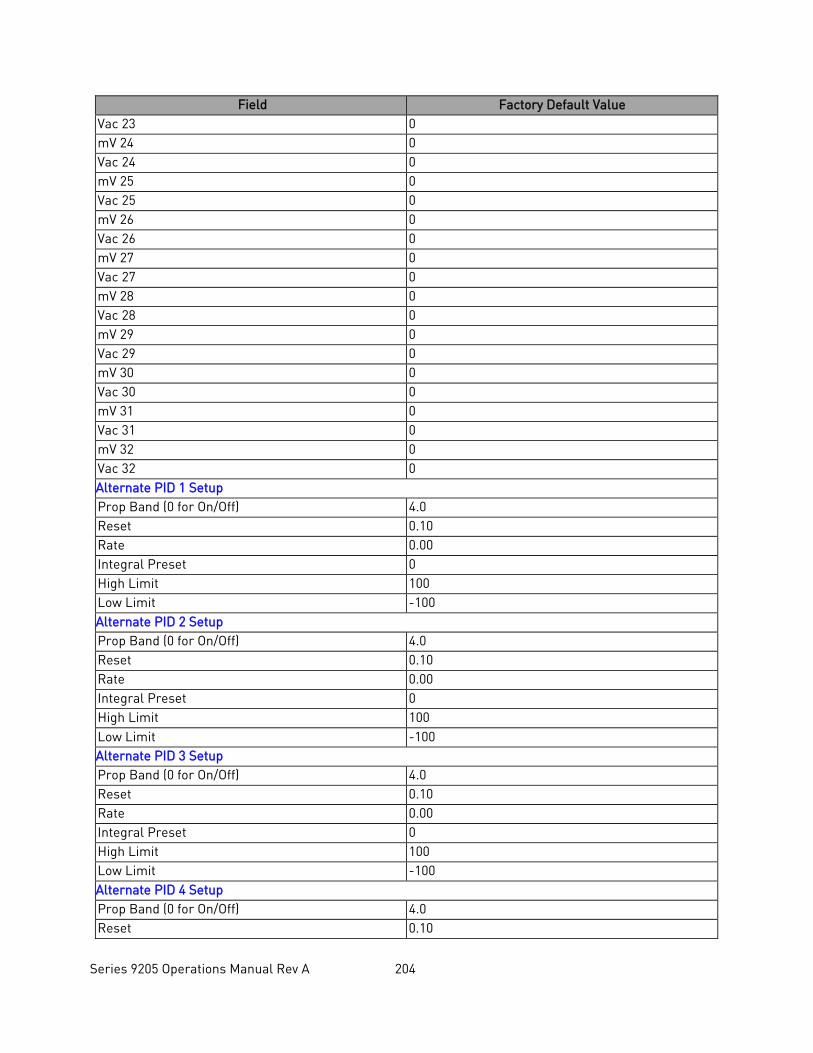
Series 9205 Operations Manual Rev A 204
Field Factory Default Value Vac 23 0 mV 24 0 Vac 24 0 mV 25 0 Vac 25 0 mV 26 0 Vac 26 0 mV 27 0 Vac 27 0 mV 28 0 Vac 28 0 mV 29 0 Vac 29 0 mV 30 0 Vac 30 0 mV 31 0 Vac 31 0 mV 32 0 Vac 32 0 Alternate PID 1 Setup Prop Band (0 for On/Off) 4.0 Reset 0.10 Rate 0.00 Integral Preset 0 High Limit 100 Low Limit -100 Alternate PID 2 Setup Prop Band (0 for On/Off) 4.0 Reset 0.10 Rate 0.00 Integral Preset 0 High Limit 100 Low Limit -100 Alternate PID 3 Setup Prop Band (0 for On/Off) 4.0 Reset 0.10 Rate 0.00 Integral Preset 0 High Limit 100 Low Limit -100 Alternate PID 4 Setup Prop Band (0 for On/Off) 4.0 Reset 0.10
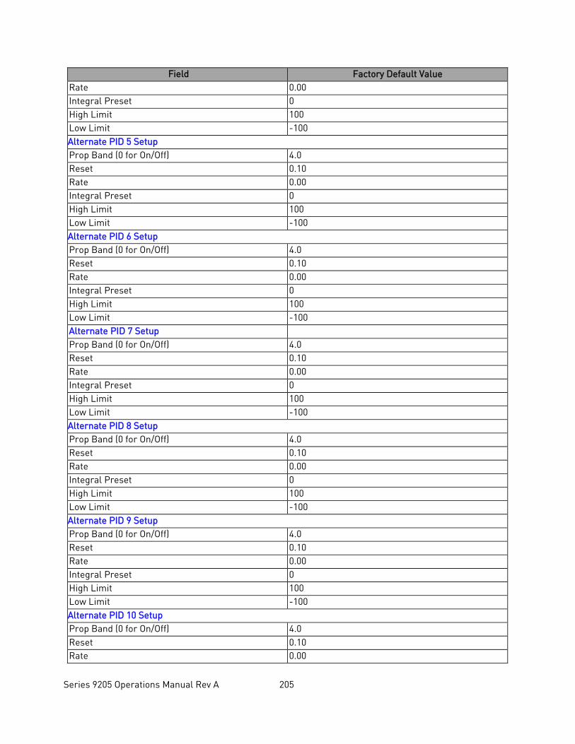
Series 9205 Operations Manual Rev A 205
Field Factory Default Value Rate 0.00 Integral Preset 0 High Limit 100 Low Limit -100 Alternate PID 5 Setup Prop Band (0 for On/Off) 4.0 Reset 0.10 Rate 0.00 Integral Preset 0 High Limit 100 Low Limit -100 Alternate PID 6 Setup Prop Band (0 for On/Off) 4.0 Reset 0.10 Rate 0.00 Integral Preset 0 High Limit 100 Low Limit -100 Alternate PID 7 Setup Prop Band (0 for On/Off) 4.0 Reset 0.10 Rate 0.00 Integral Preset 0 High Limit 100 Low Limit -100 Alternate PID 8 Setup Prop Band (0 for On/Off) 4.0 Reset 0.10 Rate 0.00 Integral Preset 0 High Limit 100 Low Limit -100 Alternate PID 9 Setup Prop Band (0 for On/Off) 4.0 Reset 0.10 Rate 0.00 Integral Preset 0 High Limit 100 Low Limit -100 Alternate PID 10 Setup Prop Band (0 for On/Off) 4.0 Reset 0.10 Rate 0.00
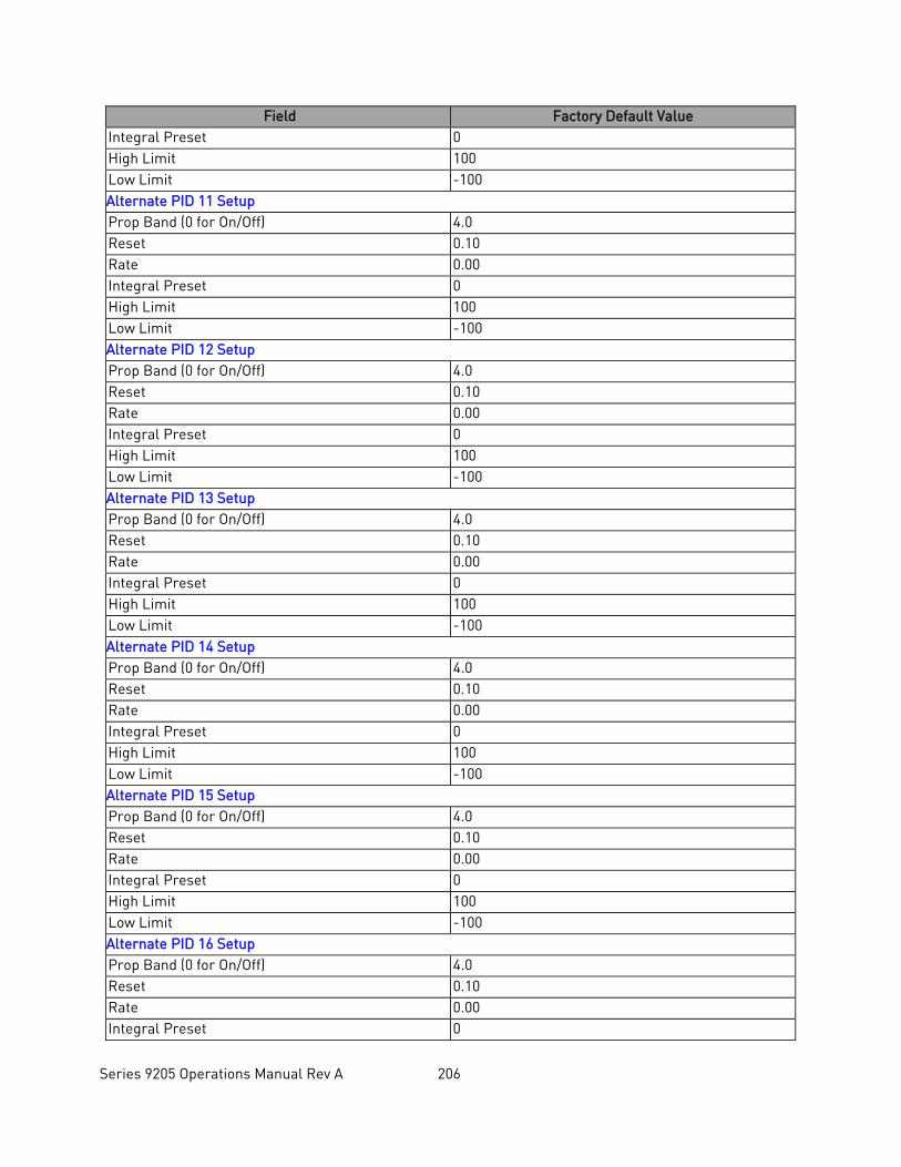
Series 9205 Operations Manual Rev A 206
Field Factory Default Value Integral Preset 0 High Limit 100 Low Limit -100 Alternate PID 11 Setup Prop Band (0 for On/Off) 4.0 Reset 0.10 Rate 0.00 Integral Preset 0 High Limit 100 Low Limit -100 Alternate PID 12 Setup Prop Band (0 for On/Off) 4.0 Reset 0.10 Rate 0.00 Integral Preset 0 High Limit 100 Low Limit -100 Alternate PID 13 Setup Prop Band (0 for On/Off) 4.0 Reset 0.10 Rate 0.00 Integral Preset 0 High Limit 100 Low Limit -100 Alternate PID 14 Setup Prop Band (0 for On/Off) 4.0 Reset 0.10 Rate 0.00 Integral Preset 0 High Limit 100 Low Limit -100 Alternate PID 15 Setup Prop Band (0 for On/Off) 4.0 Reset 0.10 Rate 0.00 Integral Preset 0 High Limit 100 Low Limit -100 Alternate PID 16 Setup Prop Band (0 for On/Off) 4.0 Reset 0.10 Rate 0.00 Integral Preset 0
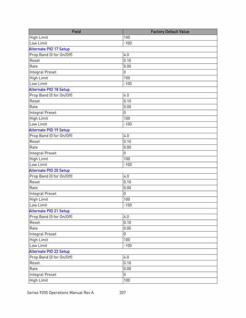
Series 9205 Operations Manual Rev A 207
Field Factory Default Value High Limit 100 Low Limit -100 Alternate PID 17 Setup Prop Band (0 for On/Off) 4.0 Reset 0.10 Rate 0.00 Integral Preset 0 High Limit 100 Low Limit -100 Alternate PID 18 Setup Prop Band (0 for On/Off) 4.0 Reset 0.10 Rate 0.00 Integral Preset 0 High Limit 100 Low Limit -100 Alternate PID 19 Setup Prop Band (0 for On/Off) 4.0 Reset 0.10 Rate 0.00 Integral Preset 0 High Limit 100 Low Limit -100 Alternate PID 20 Setup Prop Band (0 for On/Off) 4.0 Reset 0.10 Rate 0.00 Integral Preset 0 High Limit 100 Low Limit -100 Alternate PID 21 Setup Prop Band (0 for On/Off) 4.0 Reset 0.10 Rate 0.00 Integral Preset 0 High Limit 100 Low Limit -100 Alternate PID 22 Setup Prop Band (0 for On/Off) 4.0 Reset 0.10 Rate 0.00 Integral Preset 0 High Limit 100
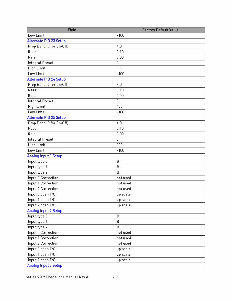
Series 9205 Operations Manual Rev A 208
Field Factory Default Value Low Limit -100 Alternate PID 23 Setup Prop Band (0 for On/Off) 4.0 Reset 0.10 Rate 0.00 Integral Preset 0 High Limit 100 Low Limit -100 Alternate PID 24 Setup Prop Band (0 for On/Off) 4.0 Reset 0.10 Rate 0.00 Integral Preset 0 High Limit 100 Low Limit -100 Alternate PID 25 Setup Prop Band (0 for On/Off) 4.0 Reset 0.10 Rate 0.00 Integral Preset 0 High Limit 100 Low Limit -100 Analog Input 1 Setup Input type 0 B Input type 1 B Input type 2 B Input 0 Correction not used Input 1 Correction not used Input 2 Correction not used Input 0 open T/C up scale Input 1 open T/C up scale Input 2 open T/C up scale Analog Input 2 Setup Input type 0 B Input type 1 B Input type 2 B Input 0 Correction not used Input 1 Correction not used Input 2 Correction not used Input 0 open T/C up scale Input 1 open T/C up scale Input 2 open T/C up scale Analog Input 3 Setup
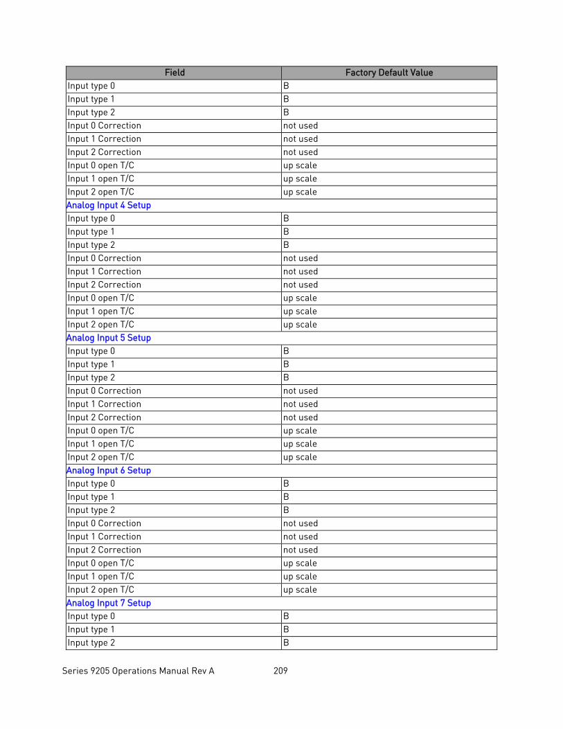
Series 9205 Operations Manual Rev A 209
Field Factory Default Value Input type 0 B Input type 1 B Input type 2 B Input 0 Correction not used Input 1 Correction not used Input 2 Correction not used Input 0 open T/C up scale Input 1 open T/C up scale Input 2 open T/C up scale Analog Input 4 Setup Input type 0 B Input type 1 B Input type 2 B Input 0 Correction not used Input 1 Correction not used Input 2 Correction not used Input 0 open T/C up scale Input 1 open T/C up scale Input 2 open T/C up scale Analog Input 5 Setup Input type 0 B Input type 1 B Input type 2 B Input 0 Correction not used Input 1 Correction not used Input 2 Correction not used Input 0 open T/C up scale Input 1 open T/C up scale Input 2 open T/C up scale Analog Input 6 Setup Input type 0 B Input type 1 B Input type 2 B Input 0 Correction not used Input 1 Correction not used Input 2 Correction not used Input 0 open T/C up scale Input 1 open T/C up scale Input 2 open T/C up scale Analog Input 7 Setup Input type 0 B Input type 1 B Input type 2 B
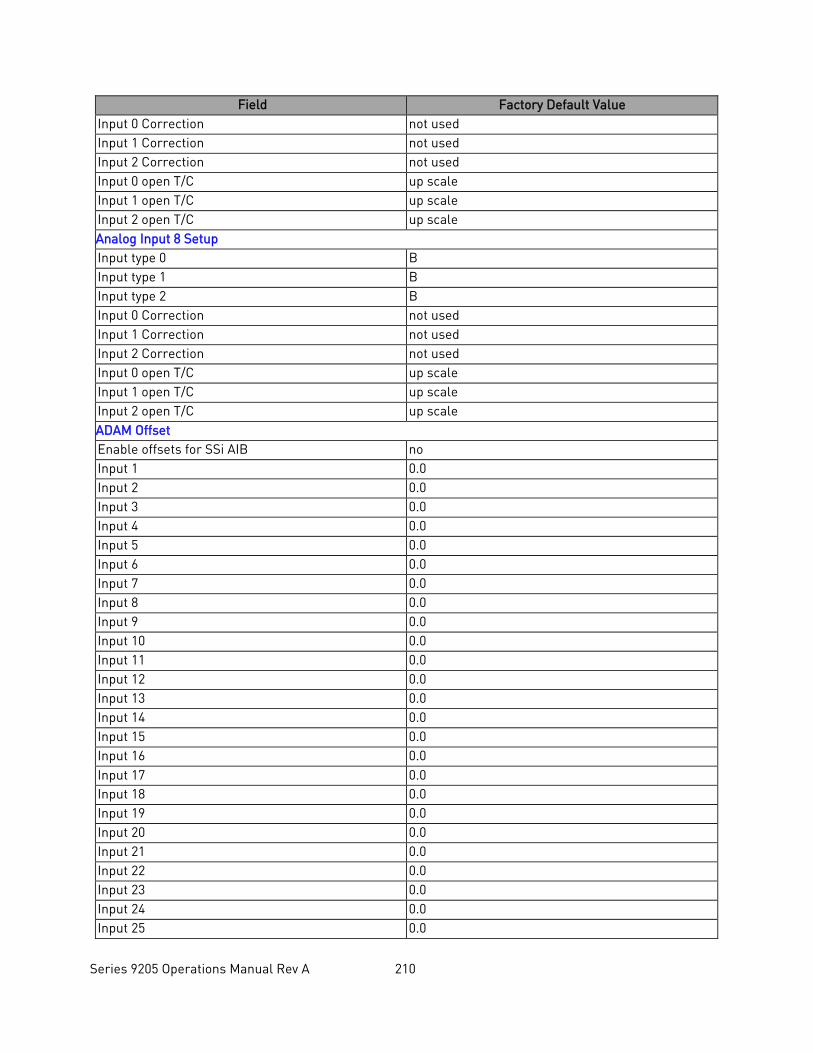
Series 9205 Operations Manual Rev A 210
Field Factory Default Value Input 0 Correction not used Input 1 Correction not used Input 2 Correction not used Input 0 open T/C up scale Input 1 open T/C up scale Input 2 open T/C up scale Analog Input 8 Setup Input type 0 B Input type 1 B Input type 2 B Input 0 Correction not used Input 1 Correction not used Input 2 Correction not used Input 0 open T/C up scale Input 1 open T/C up scale Input 2 open T/C up scale ADAM Offset Enable offsets for SSi AIB no Input 1 0.0 Input 2 0.0 Input 3 0.0 Input 4 0.0 Input 5 0.0 Input 6 0.0 Input 7 0.0 Input 8 0.0 Input 9 0.0 Input 10 0.0 Input 11 0.0 Input 12 0.0 Input 13 0.0 Input 14 0.0 Input 15 0.0 Input 16 0.0 Input 17 0.0 Input 18 0.0 Input 19 0.0 Input 20 0.0 Input 21 0.0 Input 22 0.0 Input 23 0.0 Input 24 0.0 Input 25 0.0
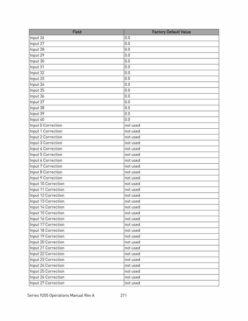
Series 9205 Operations Manual Rev A 211
Field Factory Default Value Input 26 0.0 Input 27 0.0 Input 28 0.0 Input 29 0.0 Input 30 0.0 Input 31 0.0 Input 32 0.0 Input 33 0.0 Input 34 0.0 Input 35 0.0 Input 36 0.0 Input 37 0.0 Input 38 0.0 Input 39 0.0 Input 40 0.0 Input 0 Correction not used Input 1 Correction not used Input 2 Correction not used Input 3 Correction not used Input 4 Correction not used Input 5 Correction not used Input 6 Correction not used Input 7 Correction not used Input 8 Correction not used Input 9 Correction not used Input 10 Correction not used Input 11 Correction not used Input 12 Correction not used Input 13 Correction not used Input 14 Correction not used Input 15 Correction not used Input 16 Correction not used Input 17 Correction not used Input 18 Correction not used Input 19 Correction not used Input 20 Correction not used Input 21 Correction not used Input 22 Correction not used Input 23 Correction not used Input 24 Correction not used Input 25 Correction not used Input 26 Correction not used Input 27 Correction not used
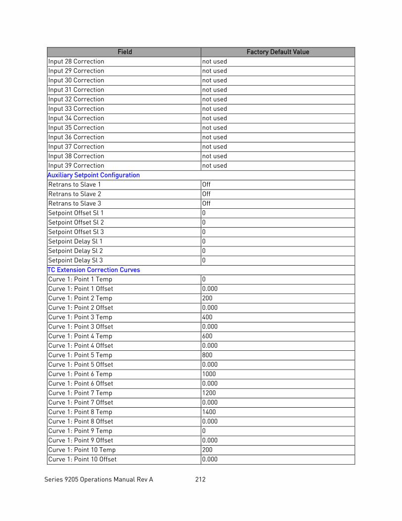
Series 9205 Operations Manual Rev A 212
Field Factory Default Value Input 28 Correction not used Input 29 Correction not used Input 30 Correction not used Input 31 Correction not used Input 32 Correction not used Input 33 Correction not used Input 34 Correction not used Input 35 Correction not used Input 36 Correction not used Input 37 Correction not used Input 38 Correction not used Input 39 Correction not used Auxiliary Setpoint Configuration Retrans to Slave 1 Off Retrans to Slave 2 Off Retrans to Slave 3 Off Setpoint Offset Sl 1 0 Setpoint Offset Sl 2 0 Setpoint Offset Sl 3 0 Setpoint Delay Sl 1 0 Setpoint Delay Sl 2 0 Setpoint Delay Sl 3 0 TC Extension Correction Curves Curve 1: Point 1 Temp 0 Curve 1: Point 1 Offset 0.000 Curve 1: Point 2 Temp 200 Curve 1: Point 2 Offset 0.000 Curve 1: Point 3 Temp 400 Curve 1: Point 3 Offset 0.000 Curve 1: Point 4 Temp 600 Curve 1: Point 4 Offset 0.000 Curve 1: Point 5 Temp 800 Curve 1: Point 5 Offset 0.000 Curve 1: Point 6 Temp 1000 Curve 1: Point 6 Offset 0.000 Curve 1: Point 7 Temp 1200 Curve 1: Point 7 Offset 0.000 Curve 1: Point 8 Temp 1400 Curve 1: Point 8 Offset 0.000 Curve 1: Point 9 Temp 0 Curve 1: Point 9 Offset 0.000 Curve 1: Point 10 Temp 200 Curve 1: Point 10 Offset 0.000
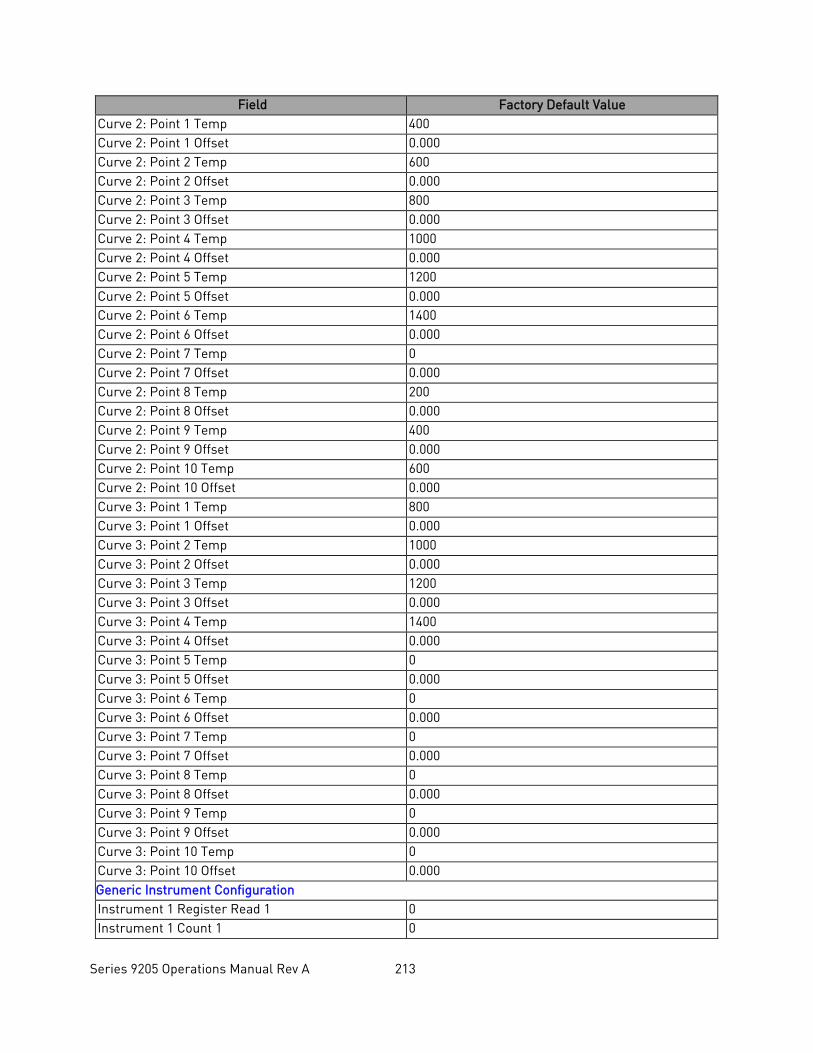
Series 9205 Operations Manual Rev A 213
Field Factory Default Value Curve 2: Point 1 Temp 400 Curve 2: Point 1 Offset 0.000 Curve 2: Point 2 Temp 600 Curve 2: Point 2 Offset 0.000 Curve 2: Point 3 Temp 800 Curve 2: Point 3 Offset 0.000 Curve 2: Point 4 Temp 1000 Curve 2: Point 4 Offset 0.000 Curve 2: Point 5 Temp 1200 Curve 2: Point 5 Offset 0.000 Curve 2: Point 6 Temp 1400 Curve 2: Point 6 Offset 0.000 Curve 2: Point 7 Temp 0 Curve 2: Point 7 Offset 0.000 Curve 2: Point 8 Temp 200 Curve 2: Point 8 Offset 0.000 Curve 2: Point 9 Temp 400 Curve 2: Point 9 Offset 0.000 Curve 2: Point 10 Temp 600 Curve 2: Point 10 Offset 0.000 Curve 3: Point 1 Temp 800 Curve 3: Point 1 Offset 0.000 Curve 3: Point 2 Temp 1000 Curve 3: Point 2 Offset 0.000 Curve 3: Point 3 Temp 1200 Curve 3: Point 3 Offset 0.000 Curve 3: Point 4 Temp 1400 Curve 3: Point 4 Offset 0.000 Curve 3: Point 5 Temp 0 Curve 3: Point 5 Offset 0.000 Curve 3: Point 6 Temp 0 Curve 3: Point 6 Offset 0.000 Curve 3: Point 7 Temp 0 Curve 3: Point 7 Offset 0.000 Curve 3: Point 8 Temp 0 Curve 3: Point 8 Offset 0.000 Curve 3: Point 9 Temp 0 Curve 3: Point 9 Offset 0.000 Curve 3: Point 10 Temp 0 Curve 3: Point 10 Offset 0.000 Generic Instrument Configuration Instrument 1 Register Read 1 0 Instrument 1 Count 1 0
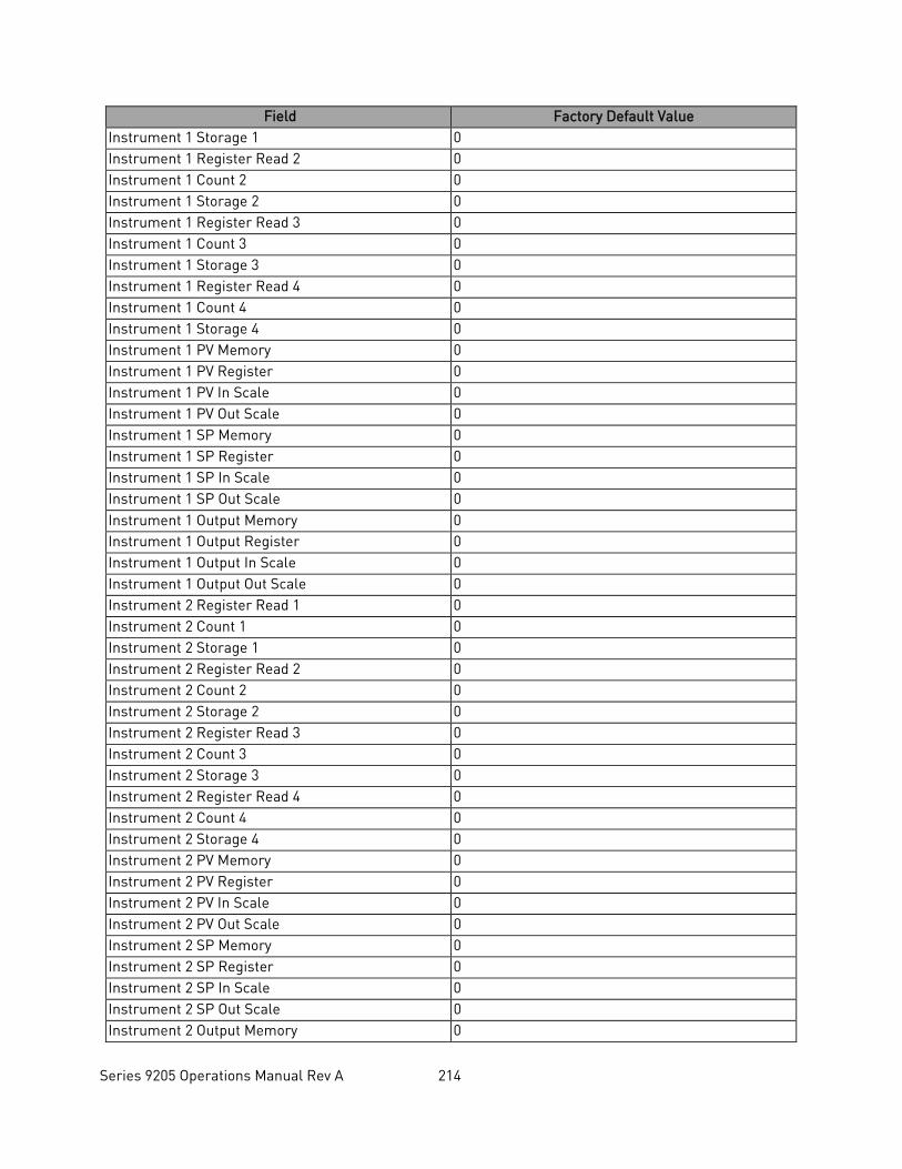
Series 9205 Operations Manual Rev A 214
Field Factory Default Value Instrument 1 Storage 1 0 Instrument 1 Register Read 2 0 Instrument 1 Count 2 0 Instrument 1 Storage 2 0 Instrument 1 Register Read 3 0 Instrument 1 Count 3 0 Instrument 1 Storage 3 0 Instrument 1 Register Read 4 0 Instrument 1 Count 4 0 Instrument 1 Storage 4 0 Instrument 1 PV Memory 0 Instrument 1 PV Register 0 Instrument 1 PV In Scale 0 Instrument 1 PV Out Scale 0 Instrument 1 SP Memory 0 Instrument 1 SP Register 0 Instrument 1 SP In Scale 0 Instrument 1 SP Out Scale 0 Instrument 1 Output Memory 0 Instrument 1 Output Register 0 Instrument 1 Output In Scale 0 Instrument 1 Output Out Scale 0 Instrument 2 Register Read 1 0 Instrument 2 Count 1 0 Instrument 2 Storage 1 0 Instrument 2 Register Read 2 0 Instrument 2 Count 2 0 Instrument 2 Storage 2 0 Instrument 2 Register Read 3 0 Instrument 2 Count 3 0 Instrument 2 Storage 3 0 Instrument 2 Register Read 4 0 Instrument 2 Count 4 0 Instrument 2 Storage 4 0 Instrument 2 PV Memory 0 Instrument 2 PV Register 0 Instrument 2 PV In Scale 0 Instrument 2 PV Out Scale 0 Instrument 2 SP Memory 0 Instrument 2 SP Register 0 Instrument 2 SP In Scale 0 Instrument 2 SP Out Scale 0 Instrument 2 Output Memory 0
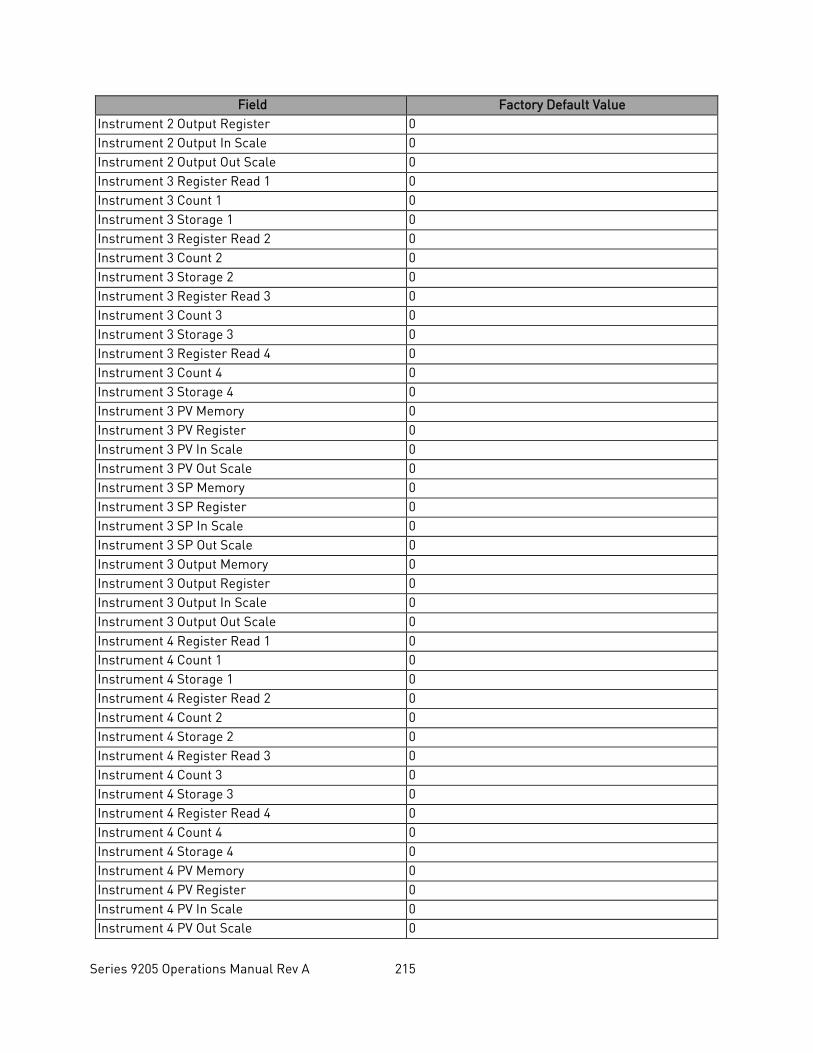
Series 9205 Operations Manual Rev A 215
Field Factory Default Value Instrument 2 Output Register 0 Instrument 2 Output In Scale 0 Instrument 2 Output Out Scale 0 Instrument 3 Register Read 1 0 Instrument 3 Count 1 0 Instrument 3 Storage 1 0 Instrument 3 Register Read 2 0 Instrument 3 Count 2 0 Instrument 3 Storage 2 0 Instrument 3 Register Read 3 0 Instrument 3 Count 3 0 Instrument 3 Storage 3 0 Instrument 3 Register Read 4 0 Instrument 3 Count 4 0 Instrument 3 Storage 4 0 Instrument 3 PV Memory 0 Instrument 3 PV Register 0 Instrument 3 PV In Scale 0 Instrument 3 PV Out Scale 0 Instrument 3 SP Memory 0 Instrument 3 SP Register 0 Instrument 3 SP In Scale 0 Instrument 3 SP Out Scale 0 Instrument 3 Output Memory 0 Instrument 3 Output Register 0 Instrument 3 Output In Scale 0 Instrument 3 Output Out Scale 0 Instrument 4 Register Read 1 0 Instrument 4 Count 1 0 Instrument 4 Storage 1 0 Instrument 4 Register Read 2 0 Instrument 4 Count 2 0 Instrument 4 Storage 2 0 Instrument 4 Register Read 3 0 Instrument 4 Count 3 0 Instrument 4 Storage 3 0 Instrument 4 Register Read 4 0 Instrument 4 Count 4 0 Instrument 4 Storage 4 0 Instrument 4 PV Memory 0 Instrument 4 PV Register 0 Instrument 4 PV In Scale 0 Instrument 4 PV Out Scale 0
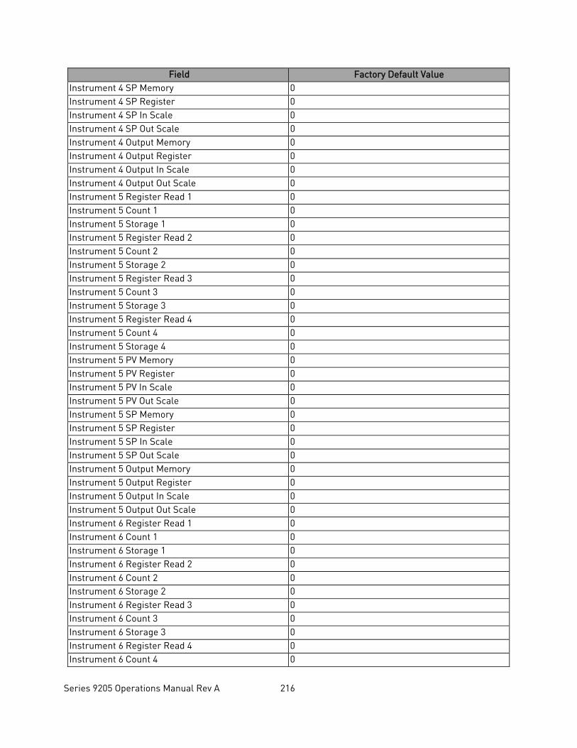
Series 9205 Operations Manual Rev A 216
Field Factory Default Value Instrument 4 SP Memory 0 Instrument 4 SP Register 0 Instrument 4 SP In Scale 0 Instrument 4 SP Out Scale 0 Instrument 4 Output Memory 0 Instrument 4 Output Register 0 Instrument 4 Output In Scale 0 Instrument 4 Output Out Scale 0 Instrument 5 Register Read 1 0 Instrument 5 Count 1 0 Instrument 5 Storage 1 0 Instrument 5 Register Read 2 0 Instrument 5 Count 2 0 Instrument 5 Storage 2 0 Instrument 5 Register Read 3 0 Instrument 5 Count 3 0 Instrument 5 Storage 3 0 Instrument 5 Register Read 4 0 Instrument 5 Count 4 0 Instrument 5 Storage 4 0 Instrument 5 PV Memory 0 Instrument 5 PV Register 0 Instrument 5 PV In Scale 0 Instrument 5 PV Out Scale 0 Instrument 5 SP Memory 0 Instrument 5 SP Register 0 Instrument 5 SP In Scale 0 Instrument 5 SP Out Scale 0 Instrument 5 Output Memory 0 Instrument 5 Output Register 0 Instrument 5 Output In Scale 0 Instrument 5 Output Out Scale 0 Instrument 6 Register Read 1 0 Instrument 6 Count 1 0 Instrument 6 Storage 1 0 Instrument 6 Register Read 2 0 Instrument 6 Count 2 0 Instrument 6 Storage 2 0 Instrument 6 Register Read 3 0 Instrument 6 Count 3 0 Instrument 6 Storage 3 0 Instrument 6 Register Read 4 0 Instrument 6 Count 4 0
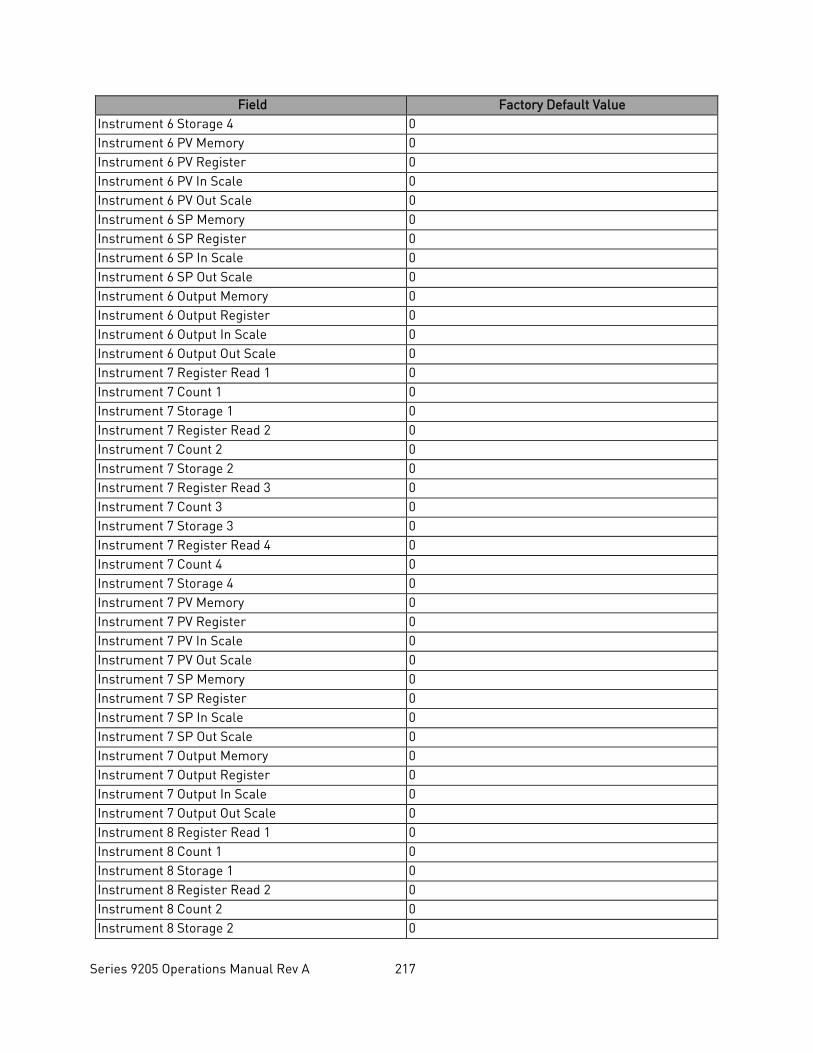
Series 9205 Operations Manual Rev A 217
Field Factory Default Value Instrument 6 Storage 4 0 Instrument 6 PV Memory 0 Instrument 6 PV Register 0 Instrument 6 PV In Scale 0 Instrument 6 PV Out Scale 0 Instrument 6 SP Memory 0 Instrument 6 SP Register 0 Instrument 6 SP In Scale 0 Instrument 6 SP Out Scale 0 Instrument 6 Output Memory 0 Instrument 6 Output Register 0 Instrument 6 Output In Scale 0 Instrument 6 Output Out Scale 0 Instrument 7 Register Read 1 0 Instrument 7 Count 1 0 Instrument 7 Storage 1 0 Instrument 7 Register Read 2 0 Instrument 7 Count 2 0 Instrument 7 Storage 2 0 Instrument 7 Register Read 3 0 Instrument 7 Count 3 0 Instrument 7 Storage 3 0 Instrument 7 Register Read 4 0 Instrument 7 Count 4 0 Instrument 7 Storage 4 0 Instrument 7 PV Memory 0 Instrument 7 PV Register 0 Instrument 7 PV In Scale 0 Instrument 7 PV Out Scale 0 Instrument 7 SP Memory 0 Instrument 7 SP Register 0 Instrument 7 SP In Scale 0 Instrument 7 SP Out Scale 0 Instrument 7 Output Memory 0 Instrument 7 Output Register 0 Instrument 7 Output In Scale 0 Instrument 7 Output Out Scale 0 Instrument 8 Register Read 1 0 Instrument 8 Count 1 0 Instrument 8 Storage 1 0 Instrument 8 Register Read 2 0 Instrument 8 Count 2 0 Instrument 8 Storage 2 0
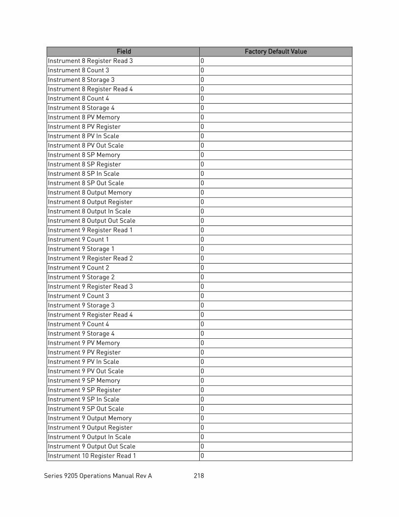
Series 9205 Operations Manual Rev A 218
Field Factory Default Value Instrument 8 Register Read 3 0 Instrument 8 Count 3 0 Instrument 8 Storage 3 0 Instrument 8 Register Read 4 0 Instrument 8 Count 4 0 Instrument 8 Storage 4 0 Instrument 8 PV Memory 0 Instrument 8 PV Register 0 Instrument 8 PV In Scale 0 Instrument 8 PV Out Scale 0 Instrument 8 SP Memory 0 Instrument 8 SP Register 0 Instrument 8 SP In Scale 0 Instrument 8 SP Out Scale 0 Instrument 8 Output Memory 0 Instrument 8 Output Register 0 Instrument 8 Output In Scale 0 Instrument 8 Output Out Scale 0 Instrument 9 Register Read 1 0 Instrument 9 Count 1 0 Instrument 9 Storage 1 0 Instrument 9 Register Read 2 0 Instrument 9 Count 2 0 Instrument 9 Storage 2 0 Instrument 9 Register Read 3 0 Instrument 9 Count 3 0 Instrument 9 Storage 3 0 Instrument 9 Register Read 4 0 Instrument 9 Count 4 0 Instrument 9 Storage 4 0 Instrument 9 PV Memory 0 Instrument 9 PV Register 0 Instrument 9 PV In Scale 0 Instrument 9 PV Out Scale 0 Instrument 9 SP Memory 0 Instrument 9 SP Register 0 Instrument 9 SP In Scale 0 Instrument 9 SP Out Scale 0 Instrument 9 Output Memory 0 Instrument 9 Output Register 0 Instrument 9 Output In Scale 0 Instrument 9 Output Out Scale 0 Instrument 10 Register Read 1 0
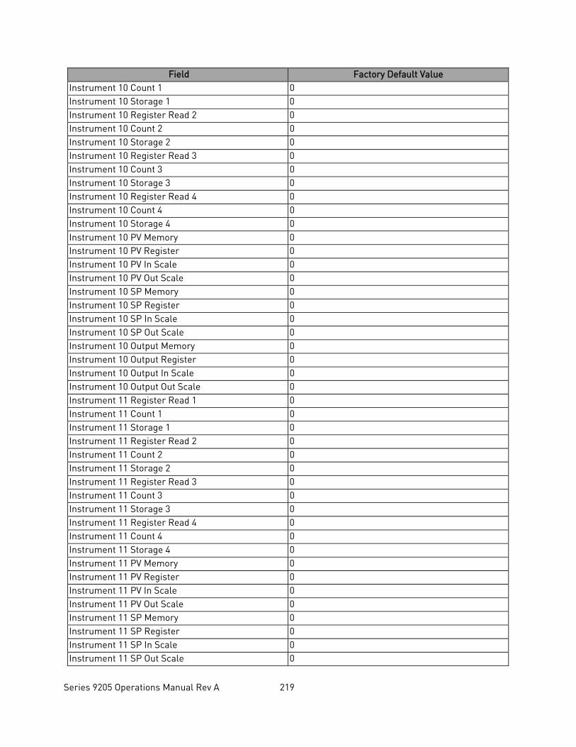
Series 9205 Operations Manual Rev A 219
Field Factory Default Value Instrument 10 Count 1 0 Instrument 10 Storage 1 0 Instrument 10 Register Read 2 0 Instrument 10 Count 2 0 Instrument 10 Storage 2 0 Instrument 10 Register Read 3 0 Instrument 10 Count 3 0 Instrument 10 Storage 3 0 Instrument 10 Register Read 4 0 Instrument 10 Count 4 0 Instrument 10 Storage 4 0 Instrument 10 PV Memory 0 Instrument 10 PV Register 0 Instrument 10 PV In Scale 0 Instrument 10 PV Out Scale 0 Instrument 10 SP Memory 0 Instrument 10 SP Register 0 Instrument 10 SP In Scale 0 Instrument 10 SP Out Scale 0 Instrument 10 Output Memory 0 Instrument 10 Output Register 0 Instrument 10 Output In Scale 0 Instrument 10 Output Out Scale 0 Instrument 11 Register Read 1 0 Instrument 11 Count 1 0 Instrument 11 Storage 1 0 Instrument 11 Register Read 2 0 Instrument 11 Count 2 0 Instrument 11 Storage 2 0 Instrument 11 Register Read 3 0 Instrument 11 Count 3 0 Instrument 11 Storage 3 0 Instrument 11 Register Read 4 0 Instrument 11 Count 4 0 Instrument 11 Storage 4 0 Instrument 11 PV Memory 0 Instrument 11 PV Register 0 Instrument 11 PV In Scale 0 Instrument 11 PV Out Scale 0 Instrument 11 SP Memory 0 Instrument 11 SP Register 0 Instrument 11 SP In Scale 0 Instrument 11 SP Out Scale 0
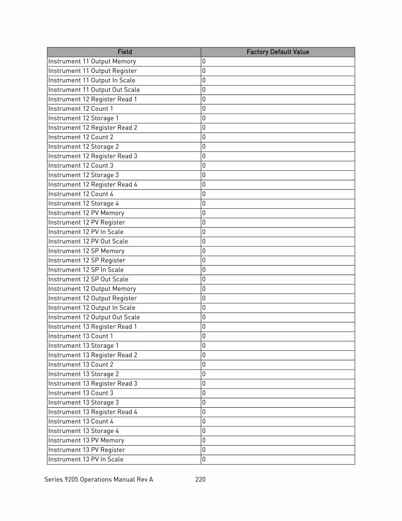
Series 9205 Operations Manual Rev A 220
Field Factory Default Value Instrument 11 Output Memory 0 Instrument 11 Output Register 0 Instrument 11 Output In Scale 0 Instrument 11 Output Out Scale 0 Instrument 12 Register Read 1 0 Instrument 12 Count 1 0 Instrument 12 Storage 1 0 Instrument 12 Register Read 2 0 Instrument 12 Count 2 0 Instrument 12 Storage 2 0 Instrument 12 Register Read 3 0 Instrument 12 Count 3 0 Instrument 12 Storage 3 0 Instrument 12 Register Read 4 0 Instrument 12 Count 4 0 Instrument 12 Storage 4 0 Instrument 12 PV Memory 0 Instrument 12 PV Register 0 Instrument 12 PV In Scale 0 Instrument 12 PV Out Scale 0 Instrument 12 SP Memory 0 Instrument 12 SP Register 0 Instrument 12 SP In Scale 0 Instrument 12 SP Out Scale 0 Instrument 12 Output Memory 0 Instrument 12 Output Register 0 Instrument 12 Output In Scale 0 Instrument 12 Output Out Scale 0 Instrument 13 Register Read 1 0 Instrument 13 Count 1 0 Instrument 13 Storage 1 0 Instrument 13 Register Read 2 0 Instrument 13 Count 2 0 Instrument 13 Storage 2 0 Instrument 13 Register Read 3 0 Instrument 13 Count 3 0 Instrument 13 Storage 3 0 Instrument 13 Register Read 4 0 Instrument 13 Count 4 0 Instrument 13 Storage 4 0 Instrument 13 PV Memory 0 Instrument 13 PV Register 0 Instrument 13 PV In Scale 0
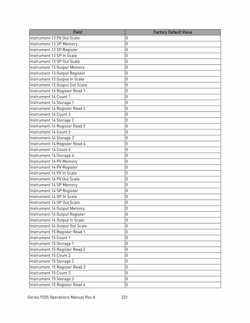
Series 9205 Operations Manual Rev A 221
Field Factory Default Value Instrument 13 PV Out Scale 0 Instrument 13 SP Memory 0 Instrument 13 SP Register 0 Instrument 13 SP In Scale 0 Instrument 13 SP Out Scale 0 Instrument 13 Output Memory 0 Instrument 13 Output Register 0 Instrument 13 Output In Scale 0 Instrument 13 Output Out Scale 0 Instrument 14 Register Read 1 0 Instrument 14 Count 1 0 Instrument 14 Storage 1 0 Instrument 14 Register Read 2 0 Instrument 14 Count 2 0 Instrument 14 Storage 2 0 Instrument 14 Register Read 3 0 Instrument 14 Count 3 0 Instrument 14 Storage 3 0 Instrument 14 Register Read 4 0 Instrument 14 Count 4 0 Instrument 14 Storage 4 0 Instrument 14 PV Memory 0 Instrument 14 PV Register 0 Instrument 14 PV In Scale 0 Instrument 14 PV Out Scale 0 Instrument 14 SP Memory 0 Instrument 14 SP Register 0 Instrument 14 SP In Scale 0 Instrument 14 SP Out Scale 0 Instrument 14 Output Memory 0 Instrument 14 Output Register 0 Instrument 14 Output In Scale 0 Instrument 14 Output Out Scale 0 Instrument 15 Register Read 1 0 Instrument 15 Count 1 0 Instrument 15 Storage 1 0 Instrument 15 Register Read 2 0 Instrument 15 Count 2 0 Instrument 15 Storage 2 0 Instrument 15 Register Read 3 0 Instrument 15 Count 3 0 Instrument 15 Storage 3 0 Instrument 15 Register Read 4 0
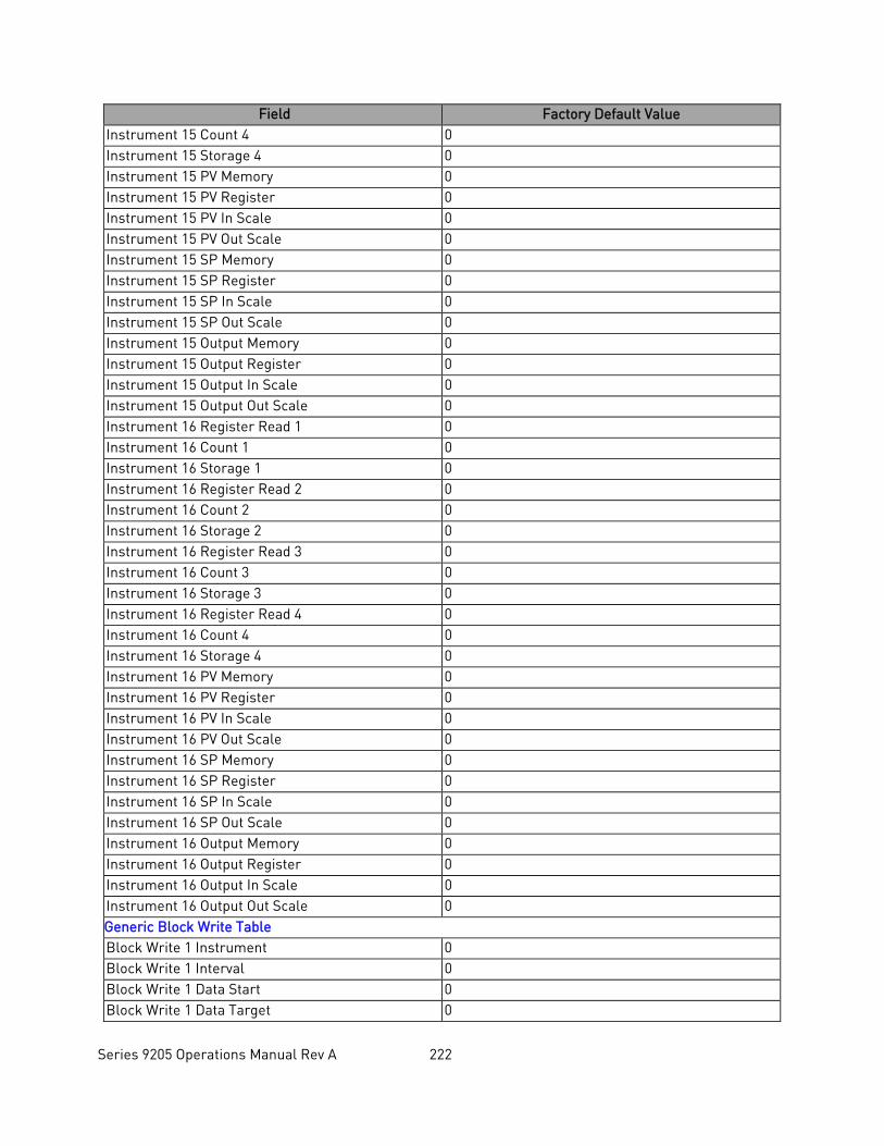
Series 9205 Operations Manual Rev A 222
Field Factory Default Value Instrument 15 Count 4 0 Instrument 15 Storage 4 0 Instrument 15 PV Memory 0 Instrument 15 PV Register 0 Instrument 15 PV In Scale 0 Instrument 15 PV Out Scale 0 Instrument 15 SP Memory 0 Instrument 15 SP Register 0 Instrument 15 SP In Scale 0 Instrument 15 SP Out Scale 0 Instrument 15 Output Memory 0 Instrument 15 Output Register 0 Instrument 15 Output In Scale 0 Instrument 15 Output Out Scale 0 Instrument 16 Register Read 1 0 Instrument 16 Count 1 0 Instrument 16 Storage 1 0 Instrument 16 Register Read 2 0 Instrument 16 Count 2 0 Instrument 16 Storage 2 0 Instrument 16 Register Read 3 0 Instrument 16 Count 3 0 Instrument 16 Storage 3 0 Instrument 16 Register Read 4 0 Instrument 16 Count 4 0 Instrument 16 Storage 4 0 Instrument 16 PV Memory 0 Instrument 16 PV Register 0 Instrument 16 PV In Scale 0 Instrument 16 PV Out Scale 0 Instrument 16 SP Memory 0 Instrument 16 SP Register 0 Instrument 16 SP In Scale 0 Instrument 16 SP Out Scale 0 Instrument 16 Output Memory 0 Instrument 16 Output Register 0 Instrument 16 Output In Scale 0 Instrument 16 Output Out Scale 0 Generic Block Write Table Block Write 1 Instrument 0 Block Write 1 Interval 0 Block Write 1 Data Start 0 Block Write 1 Data Target 0
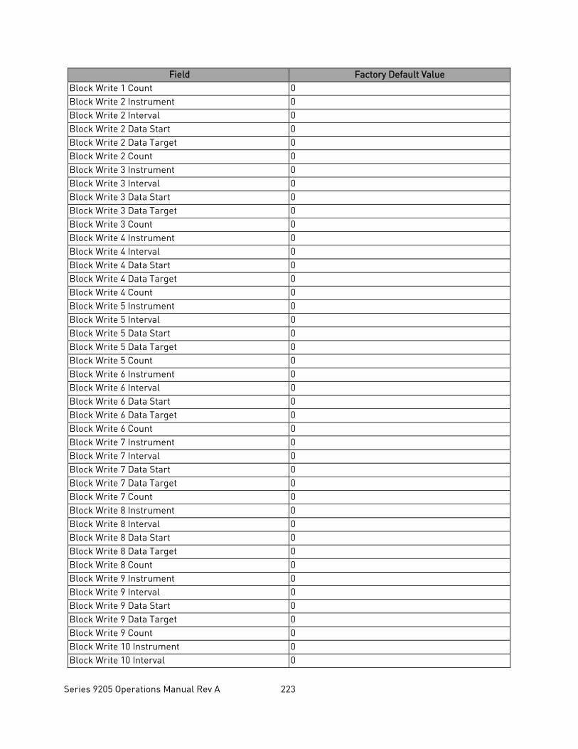
Series 9205 Operations Manual Rev A 223
Field Factory Default Value Block Write 1 Count 0 Block Write 2 Instrument 0 Block Write 2 Interval 0 Block Write 2 Data Start 0 Block Write 2 Data Target 0 Block Write 2 Count 0 Block Write 3 Instrument 0 Block Write 3 Interval 0 Block Write 3 Data Start 0 Block Write 3 Data Target 0 Block Write 3 Count 0 Block Write 4 Instrument 0 Block Write 4 Interval 0 Block Write 4 Data Start 0 Block Write 4 Data Target 0 Block Write 4 Count 0 Block Write 5 Instrument 0 Block Write 5 Interval 0 Block Write 5 Data Start 0 Block Write 5 Data Target 0 Block Write 5 Count 0 Block Write 6 Instrument 0 Block Write 6 Interval 0 Block Write 6 Data Start 0 Block Write 6 Data Target 0 Block Write 6 Count 0 Block Write 7 Instrument 0 Block Write 7 Interval 0 Block Write 7 Data Start 0 Block Write 7 Data Target 0 Block Write 7 Count 0 Block Write 8 Instrument 0 Block Write 8 Interval 0 Block Write 8 Data Start 0 Block Write 8 Data Target 0 Block Write 8 Count 0 Block Write 9 Instrument 0 Block Write 9 Interval 0 Block Write 9 Data Start 0 Block Write 9 Data Target 0 Block Write 9 Count 0 Block Write 10 Instrument 0 Block Write 10 Interval 0
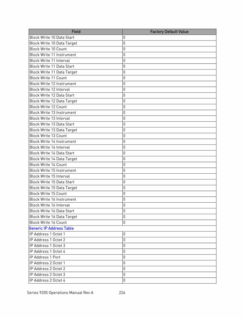
Series 9205 Operations Manual Rev A 224
Field Factory Default Value Block Write 10 Data Start 0 Block Write 10 Data Target 0 Block Write 10 Count 0 Block Write 11 Instrument 0 Block Write 11 Interval 0 Block Write 11 Data Start 0 Block Write 11 Data Target 0 Block Write 11 Count 0 Block Write 12 Instrument 0 Block Write 12 Interval 0 Block Write 12 Data Start 0 Block Write 12 Data Target 0 Block Write 12 Count 0 Block Write 13 Instrument 0 Block Write 13 Interval 0 Block Write 13 Data Start 0 Block Write 13 Data Target 0 Block Write 13 Count 0 Block Write 14 Instrument 0 Block Write 14 Interval 0 Block Write 14 Data Start 0 Block Write 14 Data Target 0 Block Write 14 Count 0 Block Write 15 Instrument 0 Block Write 15 Interval 0 Block Write 15 Data Start 0 Block Write 15 Data Target 0 Block Write 15 Count 0 Block Write 16 Instrument 0 Block Write 16 Interval 0 Block Write 16 Data Start 0 Block Write 16 Data Target 0 Block Write 16 Count 0 Generic IP Address Table IP Address 1 Octet 1 0 IP Address 1 Octet 2 0 IP Address 1 Octet 3 0 IP Address 1 Octet 4 0 IP Address 1 Port 0 IP Address 2 Octet 1 0 IP Address 2 Octet 2 0 IP Address 2 Octet 3 0 IP Address 2 Octet 4 0

Series 9205 Operations Manual Rev A 225
Field Factory Default Value IP Address 2 Port 0 IP Address 3 Octet 1 0 IP Address 3 Octet 2 0 IP Address 3 Octet 3 0 IP Address 3 Octet 4 0 IP Address 3 Port 0 IP Address 4 Octet 1 0 IP Address 4 Octet 2 0 IP Address 4 Octet 3 0 IP Address 4 Octet 4 0 IP Address 4 Port 0 IP Address 5 Octet 1 0 IP Address 5 Octet 2 0 IP Address 5 Octet 3 0 IP Address 5 Octet 4 0 IP Address 5 Port 0 IP Address 6 Octet 1 0 IP Address 6 Octet 2 0 IP Address 6 Octet 3 0 IP Address 6 Octet 4 0 IP Address 6 Port 0 IP Address 7 Octet 1 0 IP Address 7 Octet 2 0 IP Address 7 Octet 3 0 IP Address 7 Octet 4 0 IP Address 7 Port 0 IP Address 8 Octet 1 0 IP Address 8 Octet 2 0 IP Address 8 Octet 3 0 IP Address 8 Octet 4 0 IP Address 8 Port 0 IP Address 9 Octet 1 0 IP Address 9 Octet 2 0 IP Address 9 Octet 3 0 IP Address 9 Octet 4 0 IP Address 9 Port 0 IP Address 10 Octet 1 0 IP Address 10 Octet 2 0 IP Address 10 Octet 3 0 IP Address 10 Octet 4 0 IP Address 10 Port 0 IP Address 11 Octet 1 0 IP Address 11 Octet 2 0
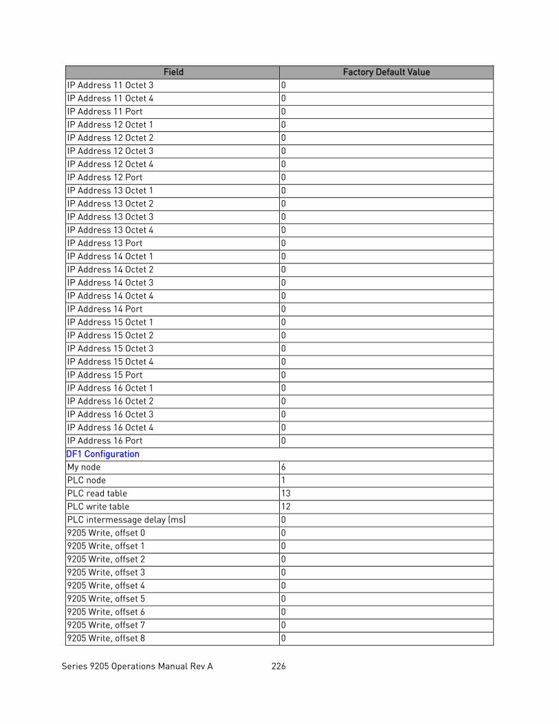
Series 9205 Operations Manual Rev A 226
Field Factory Default Value IP Address 11 Octet 3 0 IP Address 11 Octet 4 0 IP Address 11 Port 0 IP Address 12 Octet 1 0 IP Address 12 Octet 2 0 IP Address 12 Octet 3 0 IP Address 12 Octet 4 0 IP Address 12 Port 0 IP Address 13 Octet 1 0 IP Address 13 Octet 2 0 IP Address 13 Octet 3 0 IP Address 13 Octet 4 0 IP Address 13 Port 0 IP Address 14 Octet 1 0 IP Address 14 Octet 2 0 IP Address 14 Octet 3 0 IP Address 14 Octet 4 0 IP Address 14 Port 0 IP Address 15 Octet 1 0 IP Address 15 Octet 2 0 IP Address 15 Octet 3 0 IP Address 15 Octet 4 0 IP Address 15 Port 0 IP Address 16 Octet 1 0 IP Address 16 Octet 2 0 IP Address 16 Octet 3 0 IP Address 16 Octet 4 0 IP Address 16 Port 0 DF1 Configuration My node 6 PLC node 1 PLC read table 13 PLC write table 12 PLC intermessage delay (ms) 0 9205 Write, offset 0 0 9205 Write, offset 1 0 9205 Write, offset 2 0 9205 Write, offset 3 0 9205 Write, offset 4 0 9205 Write, offset 5 0 9205 Write, offset 6 0 9205 Write, offset 7 0 9205 Write, offset 8 0
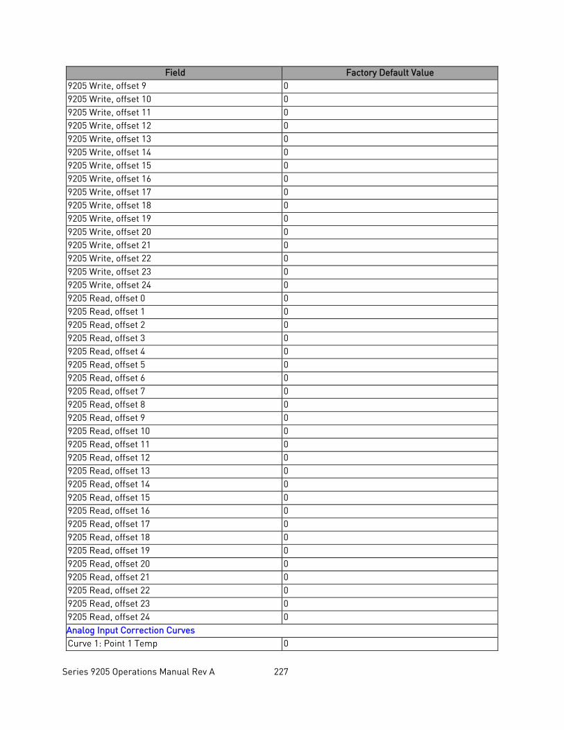
Series 9205 Operations Manual Rev A 227
Field Factory Default Value 9205 Write, offset 9 0 9205 Write, offset 10 0 9205 Write, offset 11 0 9205 Write, offset 12 0 9205 Write, offset 13 0 9205 Write, offset 14 0 9205 Write, offset 15 0 9205 Write, offset 16 0 9205 Write, offset 17 0 9205 Write, offset 18 0 9205 Write, offset 19 0 9205 Write, offset 20 0 9205 Write, offset 21 0 9205 Write, offset 22 0 9205 Write, offset 23 0 9205 Write, offset 24 0 9205 Read, offset 0 0 9205 Read, offset 1 0 9205 Read, offset 2 0 9205 Read, offset 3 0 9205 Read, offset 4 0 9205 Read, offset 5 0 9205 Read, offset 6 0 9205 Read, offset 7 0 9205 Read, offset 8 0 9205 Read, offset 9 0 9205 Read, offset 10 0 9205 Read, offset 11 0 9205 Read, offset 12 0 9205 Read, offset 13 0 9205 Read, offset 14 0 9205 Read, offset 15 0 9205 Read, offset 16 0 9205 Read, offset 17 0 9205 Read, offset 18 0 9205 Read, offset 19 0 9205 Read, offset 20 0 9205 Read, offset 21 0 9205 Read, offset 22 0 9205 Read, offset 23 0 9205 Read, offset 24 0 Analog Input Correction Curves Curve 1: Point 1 Temp 0
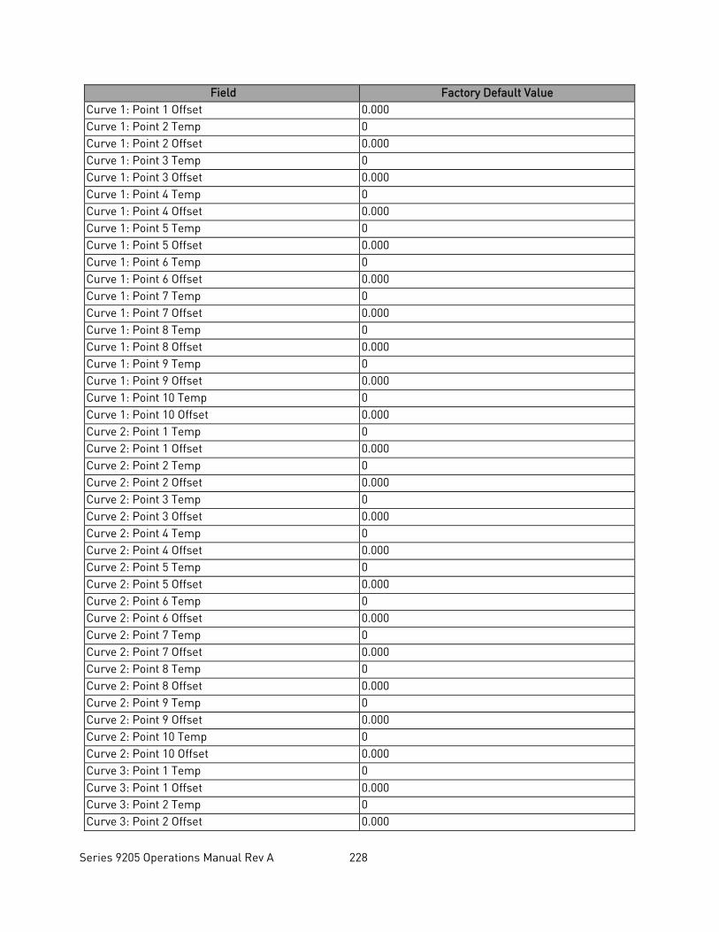
Series 9205 Operations Manual Rev A 228
Field Factory Default Value Curve 1: Point 1 Offset 0.000 Curve 1: Point 2 Temp 0 Curve 1: Point 2 Offset 0.000 Curve 1: Point 3 Temp 0 Curve 1: Point 3 Offset 0.000 Curve 1: Point 4 Temp 0 Curve 1: Point 4 Offset 0.000 Curve 1: Point 5 Temp 0 Curve 1: Point 5 Offset 0.000 Curve 1: Point 6 Temp 0 Curve 1: Point 6 Offset 0.000 Curve 1: Point 7 Temp 0 Curve 1: Point 7 Offset 0.000 Curve 1: Point 8 Temp 0 Curve 1: Point 8 Offset 0.000 Curve 1: Point 9 Temp 0 Curve 1: Point 9 Offset 0.000 Curve 1: Point 10 Temp 0 Curve 1: Point 10 Offset 0.000 Curve 2: Point 1 Temp 0 Curve 2: Point 1 Offset 0.000 Curve 2: Point 2 Temp 0 Curve 2: Point 2 Offset 0.000 Curve 2: Point 3 Temp 0 Curve 2: Point 3 Offset 0.000 Curve 2: Point 4 Temp 0 Curve 2: Point 4 Offset 0.000 Curve 2: Point 5 Temp 0 Curve 2: Point 5 Offset 0.000 Curve 2: Point 6 Temp 0 Curve 2: Point 6 Offset 0.000 Curve 2: Point 7 Temp 0 Curve 2: Point 7 Offset 0.000 Curve 2: Point 8 Temp 0 Curve 2: Point 8 Offset 0.000 Curve 2: Point 9 Temp 0 Curve 2: Point 9 Offset 0.000 Curve 2: Point 10 Temp 0 Curve 2: Point 10 Offset 0.000 Curve 3: Point 1 Temp 0 Curve 3: Point 1 Offset 0.000 Curve 3: Point 2 Temp 0 Curve 3: Point 2 Offset 0.000
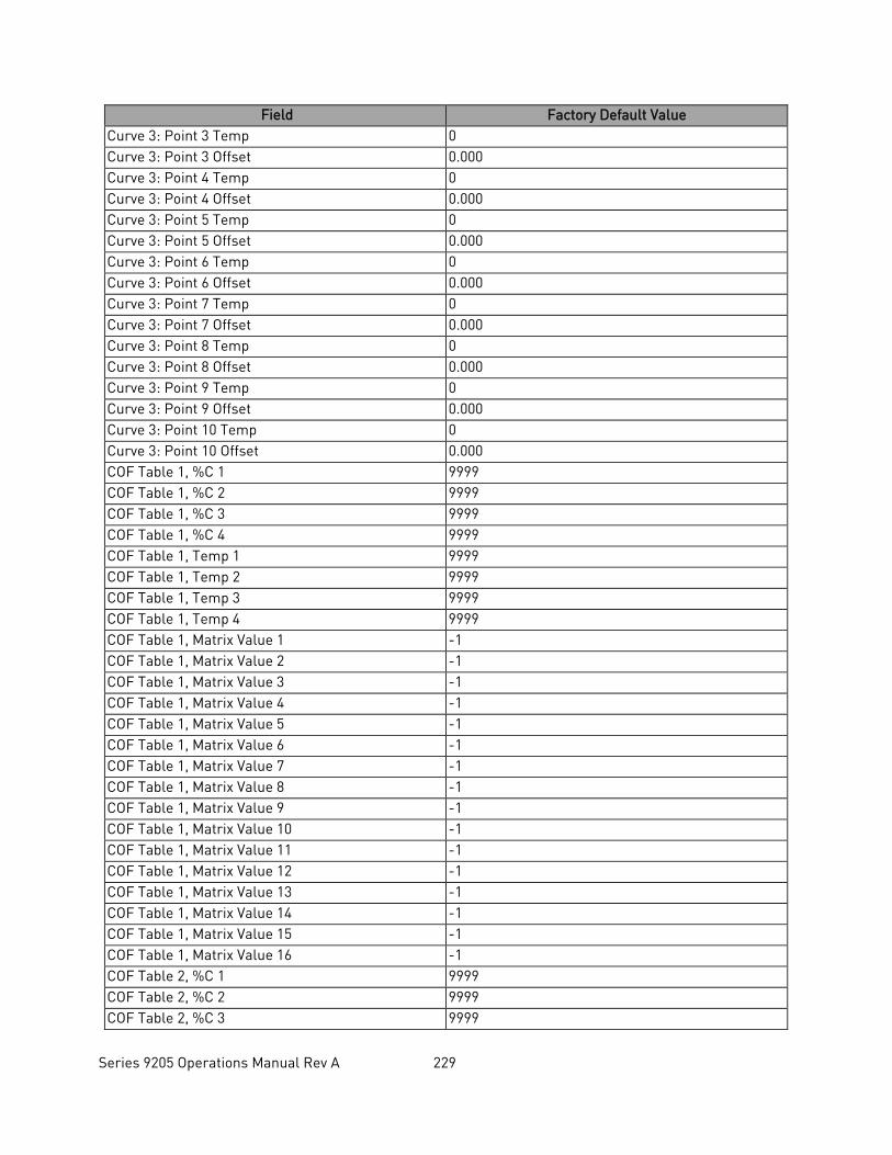
Series 9205 Operations Manual Rev A 229
Field Factory Default Value Curve 3: Point 3 Temp 0 Curve 3: Point 3 Offset 0.000 Curve 3: Point 4 Temp 0 Curve 3: Point 4 Offset 0.000 Curve 3: Point 5 Temp 0 Curve 3: Point 5 Offset 0.000 Curve 3: Point 6 Temp 0 Curve 3: Point 6 Offset 0.000 Curve 3: Point 7 Temp 0 Curve 3: Point 7 Offset 0.000 Curve 3: Point 8 Temp 0 Curve 3: Point 8 Offset 0.000 Curve 3: Point 9 Temp 0 Curve 3: Point 9 Offset 0.000 Curve 3: Point 10 Temp 0 Curve 3: Point 10 Offset 0.000 COF Table 1, %C 1 9999 COF Table 1, %C 2 9999 COF Table 1, %C 3 9999 COF Table 1, %C 4 9999 COF Table 1, Temp 1 9999 COF Table 1, Temp 2 9999 COF Table 1, Temp 3 9999 COF Table 1, Temp 4 9999 COF Table 1, Matrix Value 1 -1 COF Table 1, Matrix Value 2 -1 COF Table 1, Matrix Value 3 -1 COF Table 1, Matrix Value 4 -1 COF Table 1, Matrix Value 5 -1 COF Table 1, Matrix Value 6 -1 COF Table 1, Matrix Value 7 -1 COF Table 1, Matrix Value 8 -1 COF Table 1, Matrix Value 9 -1 COF Table 1, Matrix Value 10 -1 COF Table 1, Matrix Value 11 -1 COF Table 1, Matrix Value 12 -1 COF Table 1, Matrix Value 13 -1 COF Table 1, Matrix Value 14 -1 COF Table 1, Matrix Value 15 -1 COF Table 1, Matrix Value 16 -1 COF Table 2, %C 1 9999 COF Table 2, %C 2 9999 COF Table 2, %C 3 9999
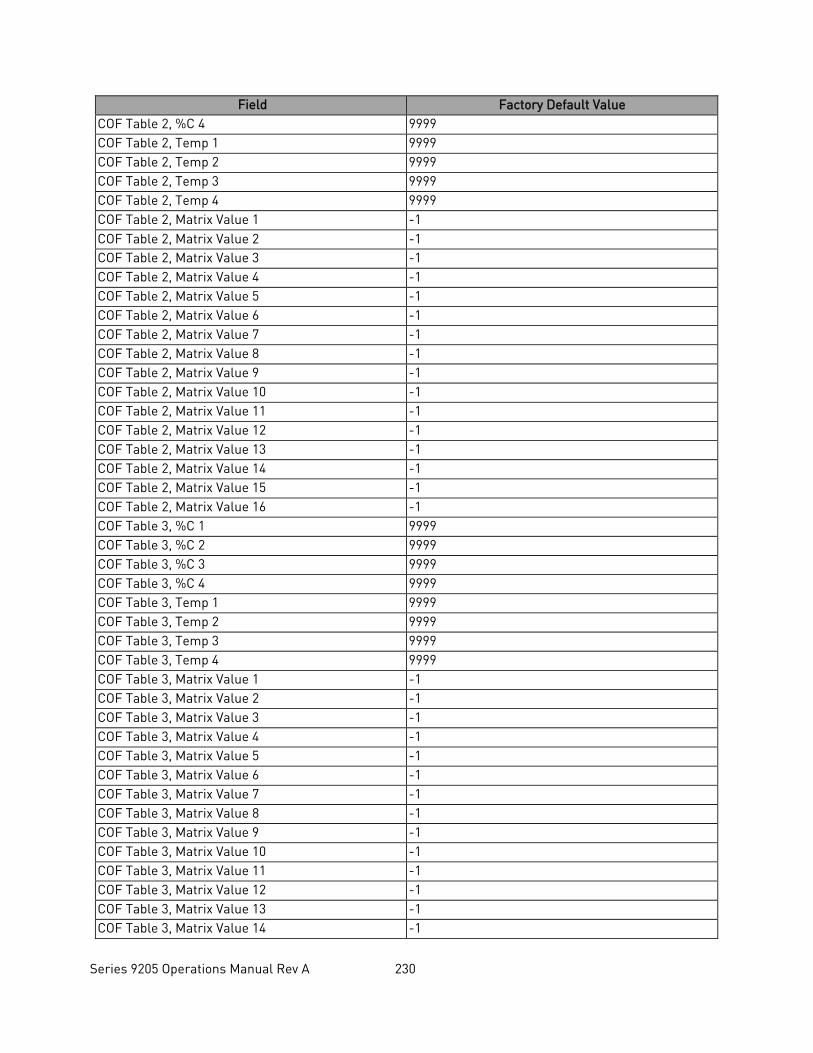
Series 9205 Operations Manual Rev A 230
Field Factory Default Value COF Table 2, %C 4 9999 COF Table 2, Temp 1 9999 COF Table 2, Temp 2 9999 COF Table 2, Temp 3 9999 COF Table 2, Temp 4 9999 COF Table 2, Matrix Value 1 -1 COF Table 2, Matrix Value 2 -1 COF Table 2, Matrix Value 3 -1 COF Table 2, Matrix Value 4 -1 COF Table 2, Matrix Value 5 -1 COF Table 2, Matrix Value 6 -1 COF Table 2, Matrix Value 7 -1 COF Table 2, Matrix Value 8 -1 COF Table 2, Matrix Value 9 -1 COF Table 2, Matrix Value 10 -1 COF Table 2, Matrix Value 11 -1 COF Table 2, Matrix Value 12 -1 COF Table 2, Matrix Value 13 -1 COF Table 2, Matrix Value 14 -1 COF Table 2, Matrix Value 15 -1 COF Table 2, Matrix Value 16 -1 COF Table 3, %C 1 9999 COF Table 3, %C 2 9999 COF Table 3, %C 3 9999 COF Table 3, %C 4 9999 COF Table 3, Temp 1 9999 COF Table 3, Temp 2 9999 COF Table 3, Temp 3 9999 COF Table 3, Temp 4 9999 COF Table 3, Matrix Value 1 -1 COF Table 3, Matrix Value 2 -1 COF Table 3, Matrix Value 3 -1 COF Table 3, Matrix Value 4 -1 COF Table 3, Matrix Value 5 -1 COF Table 3, Matrix Value 6 -1 COF Table 3, Matrix Value 7 -1 COF Table 3, Matrix Value 8 -1 COF Table 3, Matrix Value 9 -1 COF Table 3, Matrix Value 10 -1 COF Table 3, Matrix Value 11 -1 COF Table 3, Matrix Value 12 -1 COF Table 3, Matrix Value 13 -1 COF Table 3, Matrix Value 14 -1
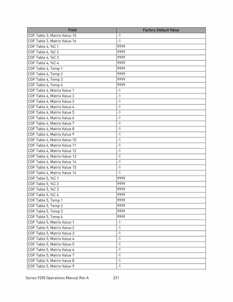
Series 9205 Operations Manual Rev A 231
Field Factory Default Value COF Table 3, Matrix Value 15 -1 COF Table 3, Matrix Value 16 -1 COF Table 4, %C 1 9999 COF Table 4, %C 2 9999 COF Table 4, %C 3 9999 COF Table 4, %C 4 9999 COF Table 4, Temp 1 9999 COF Table 4, Temp 2 9999 COF Table 4, Temp 3 9999 COF Table 4, Temp 4 9999 COF Table 4, Matrix Value 1 -1 COF Table 4, Matrix Value 2 -1 COF Table 4, Matrix Value 3 -1 COF Table 4, Matrix Value 4 -1 COF Table 4, Matrix Value 5 -1 COF Table 4, Matrix Value 6 -1 COF Table 4, Matrix Value 7 -1 COF Table 4, Matrix Value 8 -1 COF Table 4, Matrix Value 9 -1 COF Table 4, Matrix Value 10 -1 COF Table 4, Matrix Value 11 -1 COF Table 4, Matrix Value 12 -1 COF Table 4, Matrix Value 13 -1 COF Table 4, Matrix Value 14 -1 COF Table 4, Matrix Value 15 -1 COF Table 4, Matrix Value 16 -1 COF Table 5, %C 1 9999 COF Table 5, %C 2 9999 COF Table 5, %C 3 9999 COF Table 5, %C 4 9999 COF Table 5, Temp 1 9999 COF Table 5, Temp 2 9999 COF Table 5, Temp 3 9999 COF Table 5, Temp 4 9999 COF Table 5, Matrix Value 1 -1 COF Table 5, Matrix Value 2 -1 COF Table 5, Matrix Value 3 -1 COF Table 5, Matrix Value 4 -1 COF Table 5, Matrix Value 5 -1 COF Table 5, Matrix Value 6 -1 COF Table 5, Matrix Value 7 -1 COF Table 5, Matrix Value 8 -1 COF Table 5, Matrix Value 9 -1
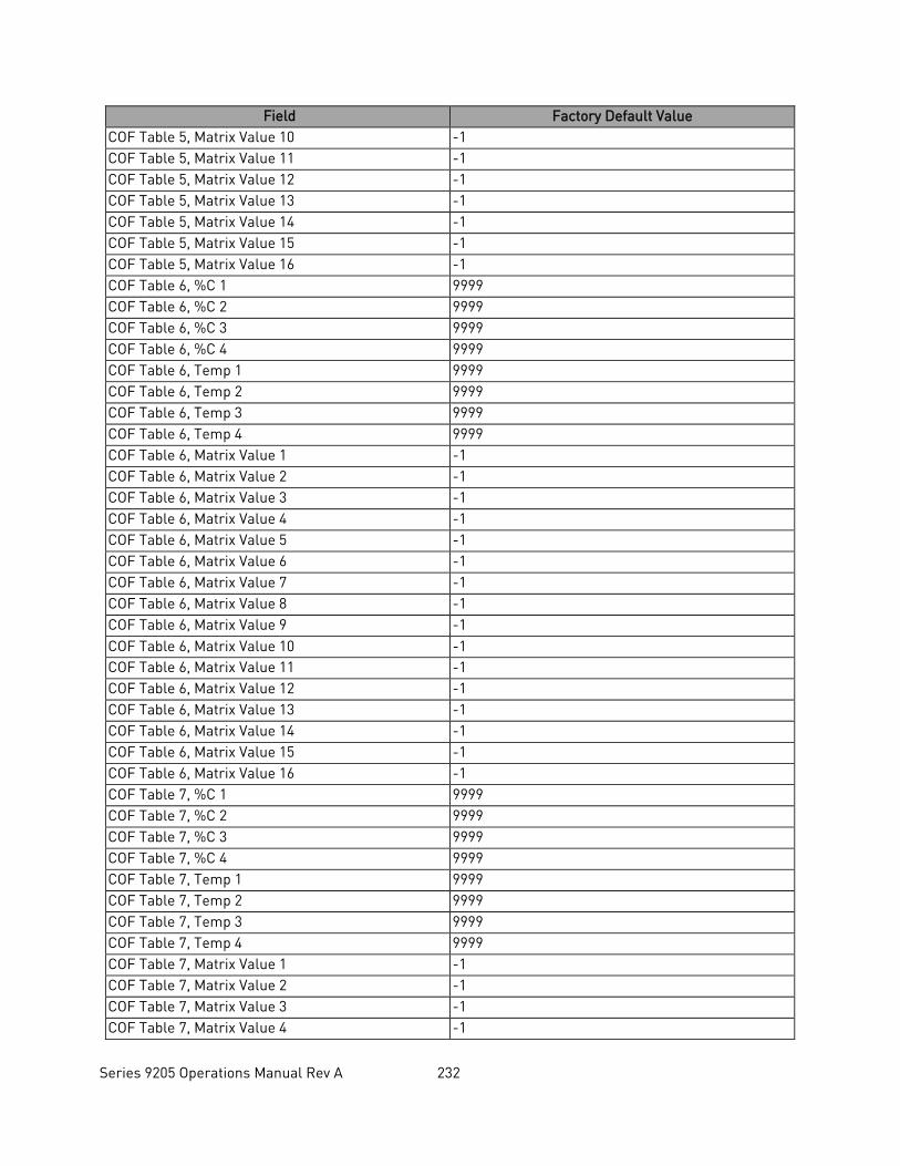
Series 9205 Operations Manual Rev A 232
Field Factory Default Value COF Table 5, Matrix Value 10 -1 COF Table 5, Matrix Value 11 -1 COF Table 5, Matrix Value 12 -1 COF Table 5, Matrix Value 13 -1 COF Table 5, Matrix Value 14 -1 COF Table 5, Matrix Value 15 -1 COF Table 5, Matrix Value 16 -1 COF Table 6, %C 1 9999 COF Table 6, %C 2 9999 COF Table 6, %C 3 9999 COF Table 6, %C 4 9999 COF Table 6, Temp 1 9999 COF Table 6, Temp 2 9999 COF Table 6, Temp 3 9999 COF Table 6, Temp 4 9999 COF Table 6, Matrix Value 1 -1 COF Table 6, Matrix Value 2 -1 COF Table 6, Matrix Value 3 -1 COF Table 6, Matrix Value 4 -1 COF Table 6, Matrix Value 5 -1 COF Table 6, Matrix Value 6 -1 COF Table 6, Matrix Value 7 -1 COF Table 6, Matrix Value 8 -1 COF Table 6, Matrix Value 9 -1 COF Table 6, Matrix Value 10 -1 COF Table 6, Matrix Value 11 -1 COF Table 6, Matrix Value 12 -1 COF Table 6, Matrix Value 13 -1 COF Table 6, Matrix Value 14 -1 COF Table 6, Matrix Value 15 -1 COF Table 6, Matrix Value 16 -1 COF Table 7, %C 1 9999 COF Table 7, %C 2 9999 COF Table 7, %C 3 9999 COF Table 7, %C 4 9999 COF Table 7, Temp 1 9999 COF Table 7, Temp 2 9999 COF Table 7, Temp 3 9999 COF Table 7, Temp 4 9999 COF Table 7, Matrix Value 1 -1 COF Table 7, Matrix Value 2 -1 COF Table 7, Matrix Value 3 -1 COF Table 7, Matrix Value 4 -1
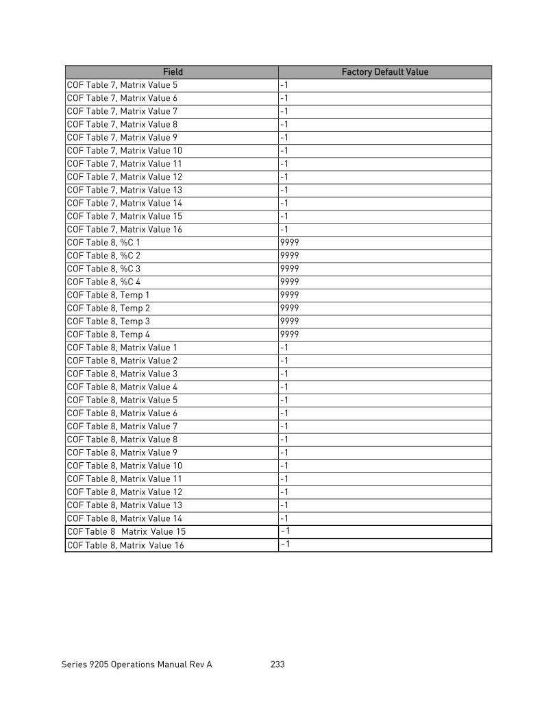
Series 9205 Operations Manual Rev A 233
Field Factory Default Value COF Table 7, Matrix Value 5 -1 COF Table 7, Matrix Value 6 -1 COF Table 7, Matrix Value 7 -1 COF Table 7, Matrix Value 8 -1 COF Table 7, Matrix Value 9 -1 COF Table 7, Matrix Value 10 -1 COF Table 7, Matrix Value 11 -1 COF Table 7, Matrix Value 12 -1 COF Table 7, Matrix Value 13 -1 COF Table 7, Matrix Value 14 -1 COF Table 7, Matrix Value 15 -1 COF Table 7, Matrix Value 16 -1 COF Table 8, %C 1 9999 COF Table 8, %C 2 9999 COF Table 8, %C 3 9999 COF Table 8, %C 4 9999 COF Table 8, Temp 1 9999 COF Table 8, Temp 2 9999 COF Table 8, Temp 3 9999 COF Table 8, Temp 4 9999 COF Table 8, Matrix Value 1 -1 COF Table 8, Matrix Value 2 -1 COF Table 8, Matrix Value 3 -1 COF Table 8, Matrix Value 4 -1 COF Table 8, Matrix Value 5 -1 COF Table 8, Matrix Value 6 -1 COF Table 8, Matrix Value 7 -1 COF Table 8, Matrix Value 8 -1 COF Table 8, Matrix Value 9 -1 COF Table 8, Matrix Value 10 -1 COF Table 8, Matrix Value 11 -1 COF Table 8, Matrix Value 12 -1 COF Table 8, Matrix Value 13 -1 COF Table 8, Matrix Value 14 -1 COF Table 8 Matrix Value 15 -1
COF Table 8, Matrix Value 16 -1

Series 9205 Operations Manual Rev A 234
Revision History
Rev. Description Date MCO # - Initial Release 2/6/2012 2092 A Touch screen and Configurator updates 7/21/2014 2102