Embed Size (px)
Citation preview
SUPER SERIES
OPERATIONS AND MAINTENANCEMANUAL
13224 Fountainhead PlazaHagerstown, MD 21742 Phone (717) 597-7111 www.jerr-dan.com
FOREWORD
This manual is intended to serve as a guide to the owner and operatorin the safe operation and optimum performance of this Jerr-Dan equip-ment.
Establishment of good operating habits and familiarity with the equip-ment and its capabilities combined with good judgement are essential.
Before attempting to operate the unit carefully read all sections of thismanual.
Rev. __________
Date _________
TABLE OF CONTENTS
Certification ...................................................................................... 0.1
Safety ............................................................................................... 1.1Decal Group ..................................................................................... 1.4
Operation .......................................................................................... 2.1
Maintenance and Lubrication ........................................................... 3.1Lubrication Chart .............................................................................. 3.3Troubleshooting ................................................................................ 3.4
1
9/14
Rev. __________
Date _________
THIS PAGE INTENTIONALLY LEFT BLANK
Rev. __________
Date _________0.1
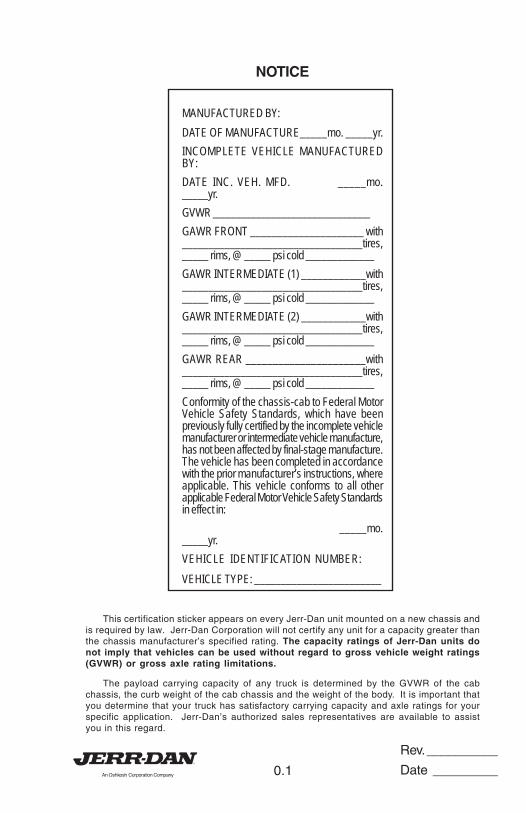
NOTICE
MANUFACTURED BY:
DATE OF MANUFACTURE_____mo. _____yr.
INCOMPLETE VEHICLE MANUFACTUREDBY:
DATE INC. VEH. MFD. _____mo._____yr.
GVWR _______________________________
GAWR FRONT _____________________ with__________________________________tires,_____ rims, @ _____ psi cold _____________
GAWR INTERMEDIATE (1) ____________with__________________________________tires,_____ rims, @ _____ psi cold _____________
GAWR INTERMEDIATE (2) ____________with__________________________________tires,_____ rims, @ _____ psi cold _____________
GAWR REAR ______________________with__________________________________tires,_____ rims, @ _____ psi cold _____________
Conformity of the chassis-cab to Federal MotorVehicle Safety Standards, which have beenpreviously fully certified by the incomplete vehiclemanufacturer or intermediate vehicle manufacture,has not been affected by final-stage manufacture.The vehicle has been completed in accordancewith the prior manufacturer’s instructions, whereapplicable. This vehicle conforms to all otherapplicable Federal Motor Vehicle Safety Standardsin effect in:
_____mo._____yr.
VEHICLE IDENTIFICATION NUMBER:
VEHICLE TYPE: ________________________
This certification sticker appears on every Jerr-Dan unit mounted on a new chassis andis required by law. Jerr-Dan Corporation will not certify any unit for a capacity greater thanthe chassis manufacturer’s specified rating. The capacity ratings of Jerr-Dan units donot imply that vehicles can be used without regard to gross vehicle weight ratings(GVWR) or gross axle rating limitations.
The payload carrying capacity of any truck is determined by the GVWR of the cabchassis, the curb weight of the cab chassis and the weight of the body. It is important thatyou determine that your truck has satisfactory carrying capacity and axle ratings for yourspecific application. Jerr-Dan’s authorized sales representatives are available to assistyou in this regard.
Rev. __________
Date _________0.2
THIS PAGE INTENTIONALLY LEFT BLANK
Rev. __________
Date _________1.1
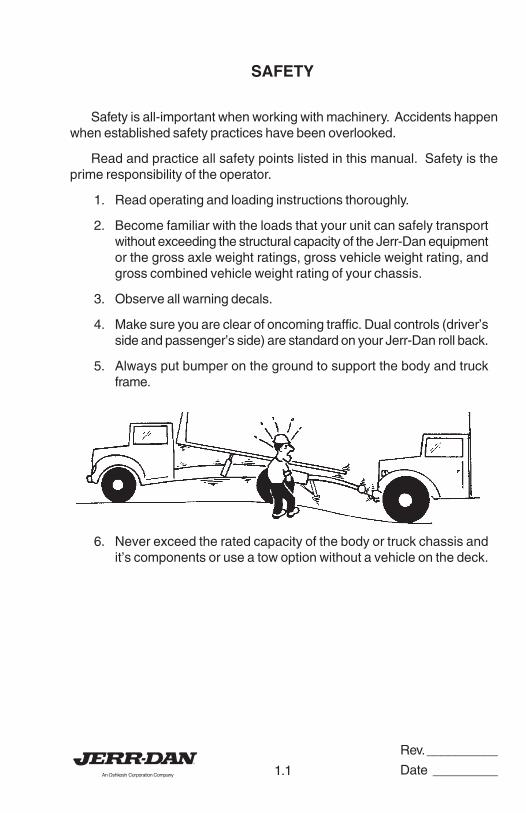
SAFETY
Safety is all-important when working with machinery. Accidents happenwhen established safety practices have been overlooked.
Read and practice all safety points listed in this manual. Safety is theprime responsibility of the operator.
1. Read operating and loading instructions thoroughly.
2. Become familiar with the loads that your unit can safely transportwithout exceeding the structural capacity of the Jerr-Dan equipmentor the gross axle weight ratings, gross vehicle weight rating, andgross combined vehicle weight rating of your chassis.
3. Observe all warning decals.
4. Make sure you are clear of oncoming traffic. Dual controls (driver’sside and passenger’s side) are standard on your Jerr-Dan roll back.
5. Always put bumper on the ground to support the body and truckframe.
6. Never exceed the rated capacity of the body or truck chassis andit’s components or use a tow option without a vehicle on the deck.
Rev. __________
Date _________1.2
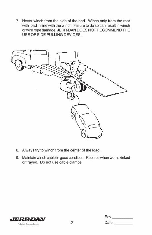
7. Never winch from the side of the bed. Winch only from the rearwith load in line with the winch. Failure to do so can result in winchor wire rope damage. JERR-DAN DOES NOT RECOMMEND THEUSE OF SIDE PULLING DEVICES.
8. Always try to winch from the center of the load.
9. Maintain winch cable in good condition. Replace when worn, kinkedor frayed. Do not use cable clamps.
Rev. __________
Date _________1.3
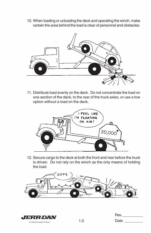
10. When loading or unloading the deck and operating the winch, makecertain the area behind the load is clear of personnel and obstacles.
11. Distribute load evenly on the deck. Do not concentrate the load onone section of the deck, to the rear of the truck axles, or use a towoption without a load on the deck.
12. Secure cargo to the deck at both the front and rear before the truckis driven. Do not rely on the winch as the only means of holdingthe load.
Rev. __________
Date _________1.4
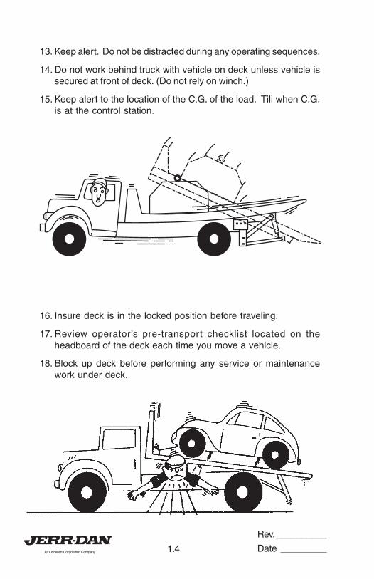
13. Keep alert. Do not be distracted during any operating sequences.
14. Do not work behind truck with vehicle on deck unless vehicle issecured at front of deck. (Do not rely on winch.)
15. Keep alert to the location of the C.G. of the load. Tili when C.G.is at the control station.
16. Insure deck is in the locked position before traveling.
17. Review operator’s pre-transport checklist located on theheadboard of the deck each time you move a vehicle.
18. Block up deck before performing any service or maintenancework under deck.
Rev. __________
Date _________1.5
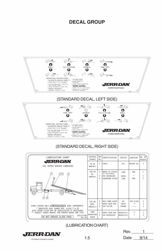
DECAL GROUP
(STANDARD DECAL, LEFT SIDE)
(STANDARD DECAL, RIGHT SIDE)
(LUBRICATION CHART)
655
DISENGAGE PTO BEFOREENGAGING TRANSMISSION.
OPERATING INSTRUCTIONSALL OPERATORS SHOULD BE TRAINED AND
USE SAFETY CHAIN FROM SUBFRAMETO TOWED VEHICLE.
ASSURE PROPER MAINTENANCE.
DO NOT OPERATE IF DAMAGED ORDEFECTIVE.
ADEQUATELY SECURE ALL LOADS.
COMPLY WITH ALL LOAD RATINGS.
TILT ONLY WHEN DECAL ALIGNS WITHFIRST CONTROL HANDLE.
CAPACITY LOADS MUST BEUNIFORMLY DISTRIBUTED.
ASSURE ENGAGEMENT OF WINCH DRUM.
ASSURE SAFETY OF ALL PERSONNEL.
UNDERSTAND THE OPERATOR'S MANUAL.
DISENGAGE PTO BEFOREENGAGING TRANSMISSION.
RETRACT TILT / STABILIZERARM BEFORE TRANSPORT.
ROLL TILT/STAB WINCH TOW OPT
656
DISENGAGE PTO BEFOREENGAGING TRANSMISSION.
OPERATING INSTRUCTIONSALL OPERATORS SHOULD BE TRAINED AND
USE SAFETY CHAIN FROM SUBFRAMETO TOWED VEHICLE.
ASSURE PROPER MAINTENANCE.
DO NOT OPERATE IF DAMAGED ORDEFECTIVE.
ADEQUATELY SECURE ALL LOADS.
COMPLY WITH ALL LOAD RATINGS.
TILT ONLY WHEN DECAL ALIGNS WITHFIRST CONTROL HANDLE.
CAPACITY LOADS MUST BEUNIFORMLY DISTRIBUTED.
ASSURE ENGAGEMENT OF WINCH DRUM.
ASSURE SAFETY OF ALL PERSONNEL.
UNDERSTAND THE OPERATOR'S MANUAL.
DISENGAGE PTO BEFOREENGAGING TRANSMISSION.
RETRACT TILT / STABILIZERARM BEFORE TRANSPORT.
ROLLTILT/STABWINCHTOW OPT
1001127494REV-00
250 OR
SEMI-
ANNUALLY
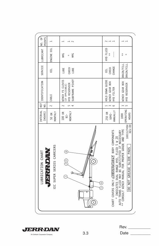
HOLD DOWN GUIDEWINCH GEAR BOX
HYD FILTER
OIL
CHECK
CHANGE
HYD FLUID
**
----
21
1
1000OPERATING
HOURS
WINCH GEAR BOX
HYD RESERVOIR
DRAIN/FILL
DRAIN/FILL**
*
1
1
LUBRICATION CHART
CHART COVERS ONLY BODY COMPONENTS* INDICATES DUAL RANGE HYD. FLUID 5 W 20
AUTO TRANS FLUID MAY BE SUBSTITUTED IF NECESSARY** CONSULT WINCH MANUAL FOR PROPER GRADE AND TYPE
50 OR
MONTHLY
INTERVAL
(HOURS)
REF
NO.IDENTIFICATION SERVICE LUBRICANT
DO NOT GREASE SLIDE PADS
NO. OFPOINTS
100 ORBI-
MONTHLY
BIC SUPER SERIES CARRIERS
2
5
4
WINCH FS CLEVIS(IF APPLICABLE)
HYD RESERVOIR
SUBFRAME PIVOT
LUBE
CHECKLUBE
MPG
*
MPG
1
1
2
CABLE 2 OIL ENGINE OIL 1
1 2 3 4
5
3
5
1
3
6
6
1
9/14
Rev. __________
Date _________1.6
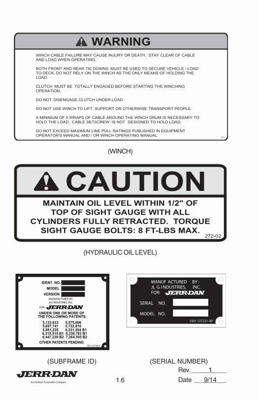
(WINCH)
CAUTIONCAUTIONMAINTAIN OIL LEVEL WITHIN 1/2" OF
TOP OF SIGHT GAUGE WITH ALL
CYLINDERS FULLY RETRACTED. TORQUE
SIGHT GAUGE BOLTS: 8 FT-LBS MAX.272-02
(HYDRAULIC OIL LEVEL)
OTHER PATENTS PENDING
UNDER ONE OR MORE OFTHE FOLLOWING PATENTS:
5,133,633 5,575,6065,697,741 5,722,810
6,315,515 B1 6,336,783 B16,447,239 B2 7,264,305 B2
5,951,235 6,231,294 B1
1001132766-A
FOR:
MANUFACTURED BY: JLG INDUSTRIES, INC.
IDENT. NO.MODEL
VERSION
(SUBFRAME ID) (SERIAL NUMBER)
012
WARNINGWINCH CABLE FAILURE MAY CAUSE INJURY OR DEATH. STAY CLEAR OF CABLE
AND LOAD WHEN OPERATING.
BOTH FRONT AND REAR TIE DOWNS MUST BE USED TO SECURE VEHICLE / LOAD
TO DECK. DO NOT RELY ON THE WINCH AS THE ONLY MEANS OF HOLDING THE
LOAD.
CLUTCH MUST BE TOTALLY ENGAGED BEFORE STARTING THE WINCHING
OPERATION.
DO NOT DISENGAGE CLUTCH UNDER LOAD.
DO NOT USE WINCH TO LIFT, SUPPORT OR OTHERWISE TRANSPORT PEOPLE.
A MINIMUM OF 5 WRAPS OF CABLE AROUND THE WINCH DRUM IS NECESSARY TO
HOLD THE LOAD. CABLE SETSCREW IS NOT DESIGNED TO HOLD LOAD.
DO NOT EXCEED MAXIMUM LINE PULL RATINGS PUBLISHED IN EQUIPMENT
OPERATOR'S MANUAL AND / OR WINCH OPERATING MANUAL.
SERIAL NO.
MODEL NO.
MANUF ACTURED BY :JL G I NDUSTRIES, INC.
1001127221-00
FOR:
1
9/14

Rev. __________
Date _________1.7
SLIDE DECK UNTILSLIDE DECK UNTIL
ARROW ALIGNS WITHARROW ALIGNS WITH
FIRST LEVERFIRST LEVER
BEFORE TILITINGBEFORE TILITING
(DECK ALIGNMENT)
(TOW OPTION WARNING)
WARNINGWARNING
391
SAFETY PIN MUST BE INSTALLED
WHILE TOWING. FULLY RETRACT
BOOM FOR RATED CAPACITY.
(WHEEL LIFT WARNING)
1
9/14
Rev. __________
Date _________1.8
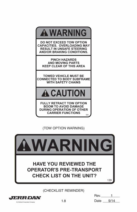
(TOW OPTION WARNING)
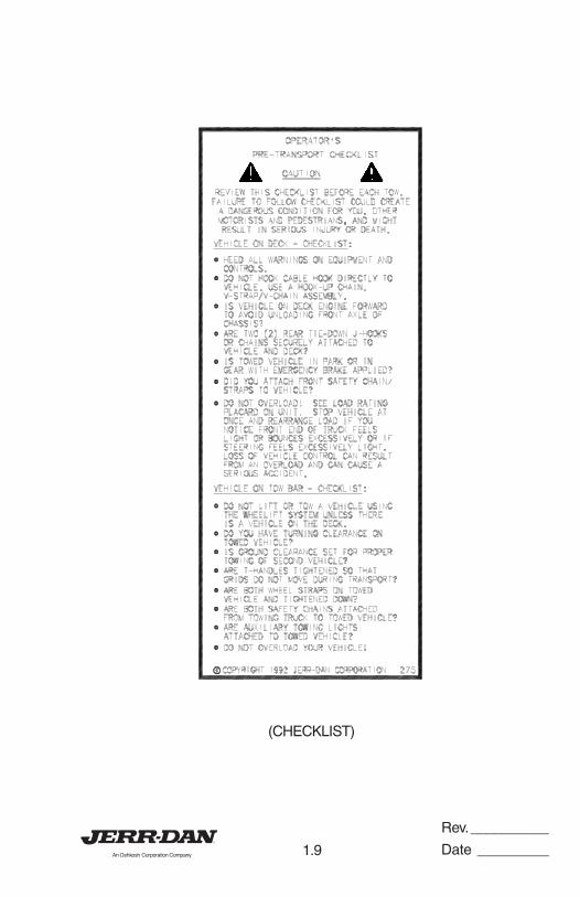
(CHECKLIST REMINDER)
WARNINGWARNING
139
HAVE YOU REVIEWED THE
OPERATOR'S PRE-TRANSPORT
CHECK LIST ON THE UNIT?
1
9/14
Rev. __________
Date _________1.9
(CHECKLIST)
Rev. __________
Date _________1.10
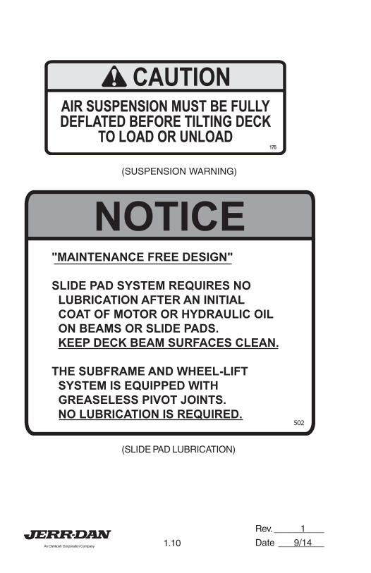
(SUSPENSION WARNING)
NOTICENOTICE
502
"MAINTENANCE FREE DESIGN"
SLIDE PAD SYSTEM REQUIRES NO
LUBRICATION AFTER AN INITIAL
COAT OF MOTOR OR HYDRAULIC OIL
ON BEAMS OR SLIDE PADS.
KEEP DECK BEAM SURFACES CLEAN.
THE SUBFRAME AND WHEEL-LIFT
SYSTEM IS EQUIPPED WITH
GREASELESS PIVOT JOINTS.
NO LUBRICATION IS REQUIRED.
(SLIDE PAD LUBRICATION)
CAUTIONCAUTION
AIR SUSPENSION MUST BE FULLY
DEFLATED BEFORE TILTING DECK
TO LOAD OR UNLOAD
AIR SUSPENSION MUST BE FULLY
DEFLATED BEFORE TILTING DECK
TO LOAD OR UNLOAD176176
1
9/14
Rev. __________
Date _________1.11
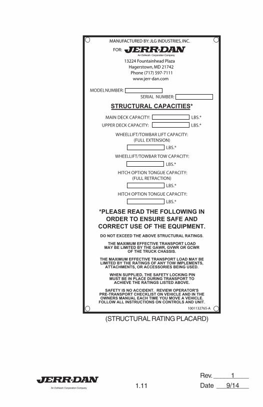
MODELNUMBER:SERIAL NUMBER:
MAIN DECK CAPACITY: LBS.*
DO NOT EXCEED THE ABOVE STRUCTURAL RATINGS.
THE MAXIMUM EFFECTIVE TRANSPORT LOADMAY BE LIMITED BY THE GAWR, GVWR OR GCWR
OF THE TRUCK CHASSIS.
THE MAXIMUM EFFECTIVE TRANSPORT LOAD MAY BELIMITED BY THE RATINGS OF ANY TOW IMPLEMENTS,
ATTACHMENTS, OR ACCESSORIES BEING USED.
WHEN SUPPLIED, THE SAFETY LOCKING PINMUST BE IN PLACE DURING TRANSPORT TO
ACHIEVE THE RATINGS LISTED ABOVE.
SAFETY IS NO ACCIDENT. REVIEW OPERATOR'SPRE-TRANSPORT CHECKLIST ON VEHICLE AND IN THEOWNERS MANUAL EACH TIME YOU MOVE A VEHICLE.
FOLLOW ALL INSTRUCTIONS ON CONTROLS AND UNIT.
UPPER DECK CAPACITY: LBS.*
WHEELLIFT/TOWBAR LIFT CAPACITY:(FULL EXTENSION)
STRUCTURAL CAPACITIES*
LBS.*
WHEELLIFT/TOWBAR TOW CAPACITY:
LBS.*
HITCH OPTION TONGUE CAPACITY:(FULL RETRACTION)
LBS.*
*PLEASE READ THE FOLLOWING INORDER TO ENSURE SAFE AND
CORRECT USE OF THE EQUIPMENT.
HITCH OPTION TONGUE CAPACITY:
LBS.*
1001132765-A
13224 Fountainhead PlazaHagerstown, MD 21742Phone (717) 597-7111
www.jerr-dan.com
FOR:
MANUFACTURED BY: JLG INDUSTRIES, INC.
(STRUCTURAL RATING PLACARD)
1
9/14
Rev. __________
Date _________1.12
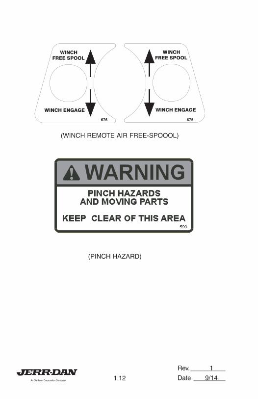
(WINCH REMOTE AIR FREE-SPOOOL)
(PINCH HAZARD)
1
9/14
Rev. __________
Date _________2.1
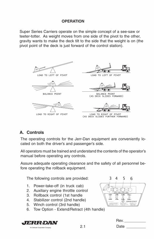
OPERATION
Super Series Carriers operate on the simple concept of a see-saw orteeter-totter. As weight moves from one side of the pivot to the other,gravity wants to make the deck tilt to the side that the weight is on (thepivot point of the deck is just forward of the control station).
BALANCE POINT
LOAD TO RIGHT OF PIVOT
LOAD TO LEFT OF PIVOTLOAD TO LEFT OF PIVOT
BALANCE POINT(AS DECK SLIDES FORWARD)
LOAD TO RIGHT OF PIVOT(AS DECK SLIDES FURTHER FORWARD)
LBS
LBS
LBSLBS
LBS
LBS
A. Controls
The operating controls for the Jerr-Dan equipment are conveniently lo-cated on both the driver’s and passenger’s side.
All operators must be trained and understand the contents of the operator’smanual before operating any controls.
Assure adequate operating clearance and the safety of all personnel be-fore operating the rollback equipment.
The following controls are provided:
1. Power-take-off (in truck cab)2. Auxiliary engine throttle control3. Rollback control (1st handle4. Stabilizer control (2nd handle)5. Winch control (3rd handle)6. Tow Option - Extend/Retract (4th handle)
370
TILT ONLY WHEN DECAL ALIGNS WITH REDCONTROL HANDLE.
HCNIW
TLIT
LLOR
OPERATING INSTRUCTIONS
DISENGAGE PTO BEFOREENGAGING TRANSMISSION.
ASSURE PROPER MAINTENANCE.
DO NOT OPERATE IF DAMAGEDOR DEFECTIVE.
USE SAFETY CHAINS FROM SUBFRAMETO TOWED VEHICLE.
ADEQUATELY SECURE ALL LOADS.
COMPLY WITH ALL LOAD RATINGS.CAPACITY LOADS MUST BEUNIFORMLY DISTRIBUTED.
ASSURE ENGAGEMENT OF WINCH DRUM.
ASSURE SAFETY OF ALL PERSONNEL.
ALL OPERATORS SHOULD BE TRAINED ANDUNDERSTAND THE OPERATOR'S MANUAL.
RABWOT
BATS
RETRACT TILT / STABILIZERARM BEFORE TRANSPORT.
3 4 5 6
Rev. __________
Date _________2.2
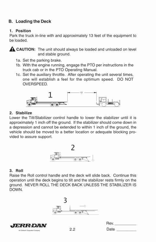
B. Loading the Deck
1. PositionPark the truck in-line with and approximately 13 feet of the equipment tobe loaded.
CAUTION: The unit should always be loaded and unloaded on leveland stable ground.
1a. Set the parking brake.1b. With the engine running, engage the PTO per instructions in the
truck cab or in the PTO Operating Manual.1c. Set the auxiliary throttle. After operating the unit several times,
one will establish a feel for the optimum speed. DO NOTOVERSPEED.
13'
1
2. StabilizeLower the Tilt/Stabilizer control handle to lower the stabilizer until it isapproximately 1 inch off the ground. If the stabilizer should come down ina depression and cannot be extended to within 1 inch of the ground, thevehicle should be moved to a better location or adequate blocking pro-vided to assure support.
2
3. RollRaise the Roll control handle and the deck will slide back. Continue thisoperation until the deck begins to tilt and the stabilizer rests firmly on theground. NEVER ROLL THE DECK BACK UNLESS THE STABILIZER ISDOWN.
3
Rev. __________
Date _________2.3
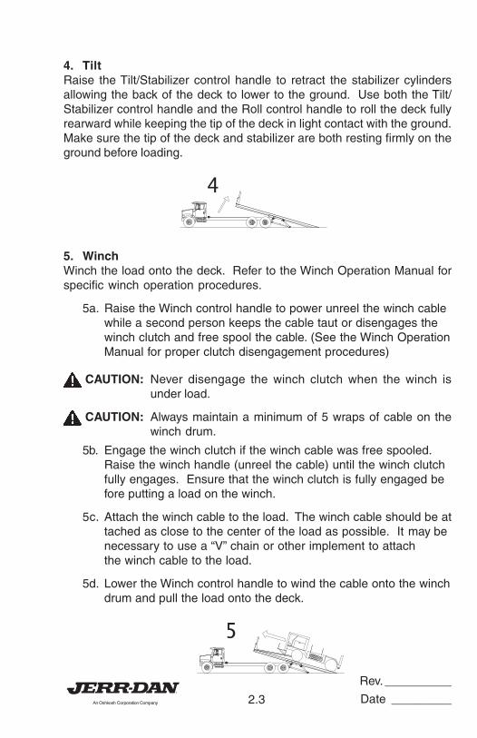
4. TiltRaise the Tilt/Stabilizer control handle to retract the stabilizer cylindersallowing the back of the deck to lower to the ground. Use both the Tilt/Stabilizer control handle and the Roll control handle to roll the deck fullyrearward while keeping the tip of the deck in light contact with the ground.Make sure the tip of the deck and stabilizer are both resting firmly on theground before loading.
4
5. WinchWinch the load onto the deck. Refer to the Winch Operation Manual forspecific winch operation procedures.
5a. Raise the Winch control handle to power unreel the winch cablewhile a second person keeps the cable taut or disengages thewinch clutch and free spool the cable. (See the Winch OperationManual for proper clutch disengagement procedures)
CAUTION: Never disengage the winch clutch when the winch isunder load.
CAUTION: Always maintain a minimum of 5 wraps of cable on thewinch drum.
5b. Engage the winch clutch if the winch cable was free spooled.Raise the winch handle (unreel the cable) until the winch clutchfully engages. Ensure that the winch clutch is fully engaged before putting a load on the winch.
5c. Attach the winch cable to the load. The winch cable should be attached as close to the center of the load as possible. It may benecessary to use a “V” chain or other implement to attachthe winch cable to the load.
5d. Lower the Winch control handle to wind the cable onto the winchdrum and pull the load onto the deck.
5
Rev. __________
Date _________2.4
CAUTION: Always winch load onto deck, NEVER drive equipmentonto the tilted deck.
CAUTION: Always maintain a uniform wrap of cable on the drum.“Nesting” of the winch cable may cause damage or pre-mature wear of the winch cable.
CAUTION: Remember that cables break, winches fail, and hooksbecome disengaged. DO NOT WORK BELOW THELOAD!
CAUTION: Replace worn or damaged cables. Always wear gloveswhen handling cable. DO NOT USE CABLE CLAMPS.
CAUTION: The winch cable should remain attached to the load andtaut.
6. Secure LoadOnce the load is positioned on the deck secure it from movement in alldirections. Set the parking brake or use wheel chocks if applicable.
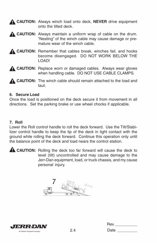
7. RollLower the Roll control handle to roll the deck forward. Use the Tilt/Stabi-lizer control handle to keep the tip of the deck in light contact with theground while rolling the deck forward. Continue this operation only untilthe balance point of the deck and load nears the control station.
CAUTION: Rolling the deck too far forward will cause the deck tolevel (tilt) uncontrolled and may cause damage to theJerr-Dan equipment, load, or truck chassis, and my causepersonal injury.
7
Rev. __________
Date _________2.5
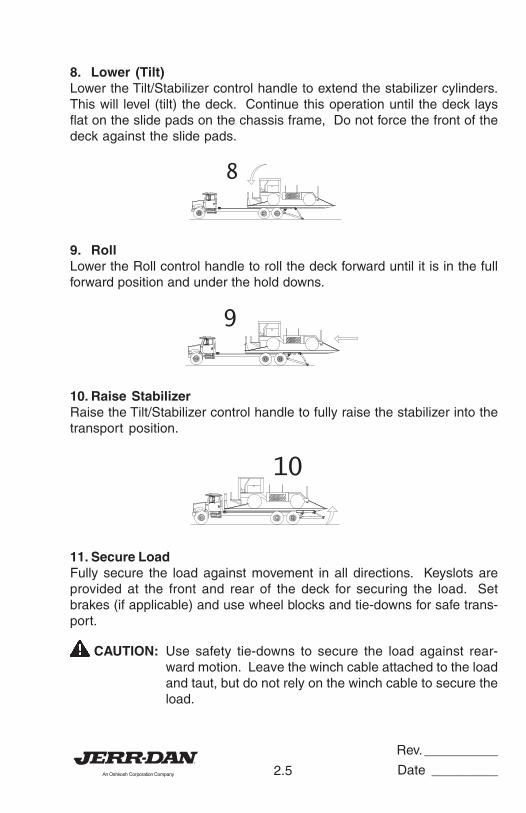
8. Lower (Tilt)Lower the Tilt/Stabilizer control handle to extend the stabilizer cylinders.This will level (tilt) the deck. Continue this operation until the deck laysflat on the slide pads on the chassis frame, Do not force the front of thedeck against the slide pads.
8
9. RollLower the Roll control handle to roll the deck forward until it is in the fullforward position and under the hold downs.
9
10. Raise StabilizerRaise the Tilt/Stabilizer control handle to fully raise the stabilizer into thetransport position.
10
11. Secure LoadFully secure the load against movement in all directions. Keyslots areprovided at the front and rear of the deck for securing the load. Setbrakes (if applicable) and use wheel blocks and tie-downs for safe trans-port.
CAUTION: Use safety tie-downs to secure the load against rear-ward motion. Leave the winch cable attached to the loadand taut, but do not rely on the winch cable to secure theload.
Rev. __________
Date _________2.6
12. Disconnect PTOReturn the engine to normal idle speed and disengage the PTO beforeengaging the transmission. Driving the truck with the PTO engaged willcause overspeeding. Overspeeding of the PTO and/or pump will greatlyshorten their life and can cause damage to the PTO, pump, and transmis-sion.
C. Unloading the Deck
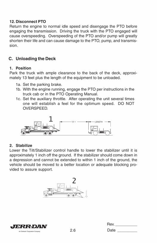
1. PositionPark the truck with ample clearance to the back of the deck, approxi-mately 13 feet plus the length of the equipment to be unloaded.
1a. Set the parking brake.1b. With the engine running, engage the PTO per instructions in the
truck cab or in the PTO Operating Manual.1c. Set the auxiliary throttle. After operating the unit several times
one will establish a feel for the optimum speed. DO NOTOVERSPEED.
LENGTH 13' +1
2. StabilizeLower the Tilt/Stabilizer control handle to lower the stabilizer until it isapproximately 1 inch off the ground. If the stabilizer should come down ina depression and cannot be extended to within 1 inch of the ground, thevehicle should be moved to a better location or adequate blocking pro-vided to assure support.
2
Rev. __________
Date _________2.7
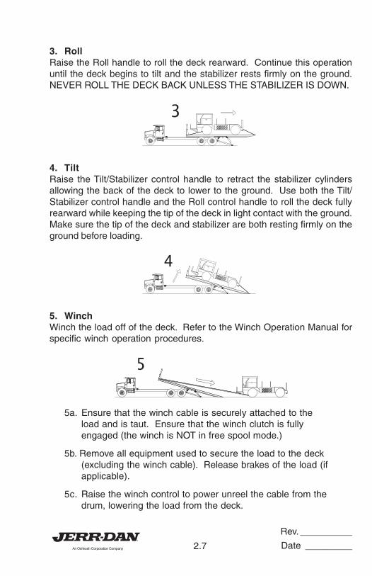
3. RollRaise the Roll handle to roll the deck rearward. Continue this operationuntil the deck begins to tilt and the stabilizer rests firmly on the ground.NEVER ROLL THE DECK BACK UNLESS THE STABILIZER IS DOWN.
3
4. TiltRaise the Tilt/Stabilizer control handle to retract the stabilizer cylindersallowing the back of the deck to lower to the ground. Use both the Tilt/Stabilizer control handle and the Roll control handle to roll the deck fullyrearward while keeping the tip of the deck in light contact with the ground.Make sure the tip of the deck and stabilizer are both resting firmly on theground before loading.
4
5. WinchWinch the load off of the deck. Refer to the Winch Operation Manual forspecific winch operation procedures.
5
5a. Ensure that the winch cable is securely attached to theload and is taut. Ensure that the winch clutch is fullyengaged (the winch is NOT in free spool mode.)
5b. Remove all equipment used to secure the load to the deck(excluding the winch cable). Release brakes of the load (ifapplicable).
5c. Raise the winch control to power unreel the cable from thedrum, lowering the load from the deck.
Rev. __________
Date _________2.8
5d. Secure the load on the ground Remove the winch cablefrom the load and store the cable.
CAUTION: Never disengage the winch clutch when the winch isunder load.
CAUTION: Always maintain a minimum of 5 wraps of cable on thewinch drum.
CAUTION: Always winch load off of the deck, NEVER drive equip-ment on the tilted deck.
CAUTION: Always maintain a uniform wrap of cable on the drum.“Nesting” of the winch cable may cause damage or pre-mature wear of the winch cable.
CAUTION: Remember that cables break, winches fail, and hooksbecome disengaged. DON’T WORK BELOW THE LOAD!
CAUTION: Replace worn or damaged cables. Always wear gloveswhen handling cable. DO NOT USE CABLE CLAMPS!
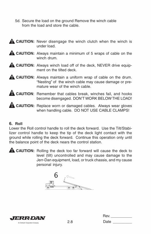
6. RollLower the Roll control handle to roll the deck forward. Use the Tilt/Stabi-lizer control handle to keep the tip of the deck light contact with theground while rolling the deck forward. Continue this operation only untilthe balance point of the deck nears the control station.
CAUTION: Rolling the deck too far forward will cause the deck tolevel (tilt) uncontrolled and may cause damage to theJerr-Dan equipment, load, or truck chassis, and my causepersonal injury.
6
Rev. __________
Date _________2.9
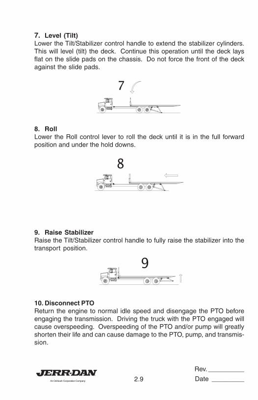
7. Level (Tilt)Lower the Tilt/Stabilizer control handle to extend the stabilizer cylinders.This will level (tilt) the deck. Continue this operation until the deck laysflat on the slide pads on the chassis. Do not force the front of the deckagainst the slide pads.
7
8. RollLower the Roll control lever to roll the deck until it is in the full forwardposition and under the hold downs.
8
9. Raise StabilizerRaise the Tilt/Stabilizer control handle to fully raise the stabilizer into thetransport position.
9
10. Disconnect PTOReturn the engine to normal idle speed and disengage the PTO beforeengaging the transmission. Driving the truck with the PTO engaged willcause overspeeding. Overspeeding of the PTO and/or pump will greatlyshorten their life and can cause damage to the PTO, pump, and transmis-sion.
Rev. __________
Date _________2.10
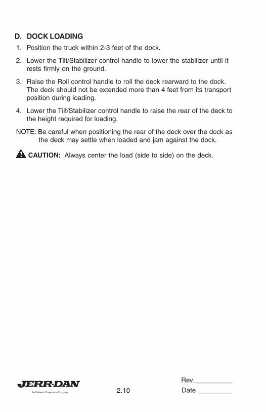
D. DOCK LOADING
1. Position the truck within 2-3 feet of the dock.
2. Lower the Tilt/Stabilizer control handle to lower the stabilizer until itrests firmly on the ground.
3. Raise the Roll control handle to roll the deck rearward to the dock.The deck should not be extended more than 4 feet from its transportposition during loading.
4. Lower the Tilt/Stabilizer control handle to raise the rear of the deck tothe height required for loading.
NOTE: Be careful when positioning the rear of the deck over the dock asthe deck may settle when loaded and jam against the dock.
CAUTION: Always center the load (side to side) on the deck.
Rev. __________
Date _________3.1
MAINTENANCE AND LUBRICATION
Jerr-Dan rollback truck decks are designed for years of service with littlemaintenance. This small amount of maintenance, however, is very impor-tant for durability and for safe operation of the deck.
Maintenance is an owner/user responsibility as neither the manufacturernor the distributor can normally control this function.
Use only safe practices when maintaining this equipment. Never get undera tilted deck unless it is adequately supported (don’t rely on the hydraulicsystem). Always shut off the engine before reaching into pinch areas aswhen checking the hydraulic oil level or greasing under the deck. Maintaina clean shop for safety. Clean up spilled oil immediately.
Inspect the vehicle and deck system periodically for damage or evidenceof pending failure. Damaged or broken parts should be replaced immedi-ately. Never operate a machine which is known to be defective or operat-ing improperly. The cause of any binding or leakage should be determinedimmediately and the problem promptly fixed.
Sliding surfaces of deck beams are to be cleaned and coated with engineoil periodically. Cleaning every six (6) months is recommended for normalhighway operations, but this frequency will vary appreciably with the typeof service. Sliding on dirty wear surfaces will cause rapid wear. Fittings onlinkage pivots should be greased every two (2) months, again dependingupon usage. See Lube Chart.
Check the hydraulic oil level bimonthly or after any leakage. Use 5W20Dual Range hydraulic oil. (Automatic transmission fluid may be used in thehydraulic system if necessary.)
The proper oil level is best checked by rolling the deck back enough to gainaccess to the fill plug (unless the chassis configuration caused the oil tankto be mounted abnormally far to the rear). The oil tank should be about2/3 full with the deck so positioned (shut off the engine after moving thedeck). This will result in a 3/4 full tank with the cylinders fully retracted(deck fully forward). (Proper oil level is achieved when the hydraulic oil iswithin 1/2 inch of top of sight tube.)
Rev. __________
Date _________3.2
The hydraulic filter located on the return side of the hydraulic tank comesequipped with a restriction indicator gauge. This gauge shows the opera-tor the condition of the filter element. When the needle reaches the redband (25 psi), the filter is starting to bypass and the element needs to bechanged. Failure to change the element will result in premature wear and/or failure of any or all of the hydraulic components. Only check gaugewith hydraulic fluid at operating temperatures. Cold oil is more denseand will give a false indicator gauge reading.
If a cylinder seal leaks, disassemble the cylinder and ascertain the causeof the leak. Small scores caused by chips or contaminated fluid can usu-ally be worked out with fine emory cloth to avoid repetition of the trouble.Whenever any seal replacement is necessary, it is always advisable toreplace all seals in that component. These seals are available in kits. Also,thoroughly clean all components before reassembly.
Rev. __________
Date _________3.3
1001127494
REV-00
250 OR
SEMI-
ANNUALLY
HOLD DOW
N GUIDE
WINCH GE
AR BOX
HYD FILT
ER
OIL
CHECK
CHANGE
HYD FLUI
D
** ----
2 1 1
1000
OPERATIN
G
HOURS
WINCH GE
AR BOX
HYD RESE
RVOIR
DRAIN/FI
LL
DRAIN/FI
LL** *
1 1
LUBRICATION CHART
CHAR
T CO
VERS
ONL
Y
BO
DY C
OMPO
NENT
S*
INDI
CATE
S DU
AL R
ANGE
HYD
. FL
UID
5 W
20AU
TO T
RANS
FLU
ID M
AY B
E SU
BSTI
TUTE
D IF
NEC
ESSA
RY**
CON
SULT
WIN
CH M
ANUA
L FO
R PR
OPER
GRA
DE A
ND T
YPE
50 OR
MONTHLY
INTERVAL
(HOURS)
REF
NO.
IDENTIFI
CATION
SERVICE
LUBRICAN
T
DO NOT GREASE SLIDE PADS
NO. OF
POINTS
100 OR
BI-
MONTHLY
BIC SUPER SERIES CARRIERS
2 5 4
WINCH FS
CLEVIS
(IF
APPL
ICAB
LE)
HYD RESE
RVOIR
SUBFRAME PIVOT
LUBE
CHECK
LUBE
MPG
*
MPG
1
1
2
CABLE
2OIL
ENGINE O
IL1
12
34
5
3 5 1 3 6
6
Rev. __________
Date _________3.4
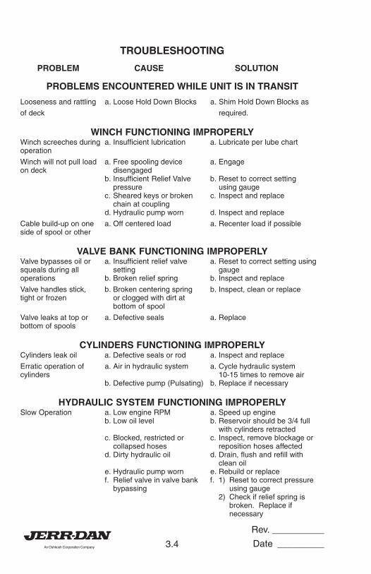
TROUBLESHOOTING
PROBLEM CAUSE SOLUTION
PROBLEMS ENCOUNTERED WHILE UNIT IS IN TRANSIT
Looseness and rattling a. Loose Hold Down Blocks a. Shim Hold Down Blocks as
of deck required.
WINCH FUNCTIONING IMPROPERLYWinch screeches during a. Insufficient lubrication a. Lubricate per lube chartoperation
Winch will not pull load a. Free spooling device a. Engageon deck disengaged
b. Insufficient Relief Valve b. Reset to correct settingpressure using gauge
c. Sheared keys or broken c. Inspect and replacechain at coupling
d. Hydraulic pump worn d. Inspect and replace
Cable build-up on one a. Off centered load a. Recenter load if possibleside of spool or other
VALVE BANK FUNCTIONING IMPROPERLYValve bypasses oil or a. Insufficient relief valve a. Reset to correct setting usingsqueals during all setting gaugeoperations b. Broken relief spring b. Inspect and replace
Valve handles stick, b. Broken centering spring b. Inspect, clean or replacetight or frozen or clogged with dirt at
bottom of spool
Valve leaks at top or a. Defective seals a. Replacebottom of spools
CYLINDERS FUNCTIONING IMPROPERLYCylinders leak oil a. Defective seals or rod a. Inspect and replace
Erratic operation of a. Air in hydraulic system a. Cycle hydraulic systemcylinders 10-15 times to remove air
b. Defective pump (Pulsating) b. Replace if necessary
HYDRAULIC SYSTEM FUNCTIONING IMPROPERLYSlow Operation a. Low engine RPM a. Speed up engine
b. Low oil level b. Reservoir should be 3/4 fullwith cylinders retracted
c. Blocked, restricted or c. Inspect, remove blockage orcollapsed hoses reposition hoses affected
d. Dirty hydraulic oil d. Drain, flush and refill withclean oil
e. Hydraulic pump worn e. Rebuild or replacef. Relief valve in valve bank f. 1) Reset to correct pressure
bypassing using gauge2) Check if relief spring is
broken. Replace ifnecessary
Rev. __________
Date _________3.5
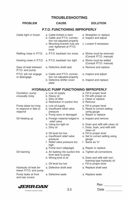
PROBLEM CAUSE SOLUTION
P.T.O. FUNCTIONING IMPROPERLY
Cable tight or frozen a. Cable kinked or bent a. Straighten or replaceb. Cable and P.T.O. connec- b. Inspect and adjust
tion not adjusted properlyc. Mounting bracket nuts are c. Loosen if necessary
over tightened at P.T.O.knob
Rattling noise in P.T.O. a. P.T.O. backlash too loose a. Shims must be removed(Consult P.T.O. manual)
Howling noise in P.T.O. a. P.T.O. backlash too tight a. Shims must be added(Consult P.T.O. manual)
Gear oil leak between a. Defective shaft seal a. Remove and replaceP.T.O. and pump
P.T.O. will not engage a. Cable and P.T.O. connec- a. Inspect and adjustor disengage tion not adjusted properly
b. Defective shifter cover b. Inspect and replaceplate
HYDRAULIC PUMP FUNCTIONING IMPROPERLYCavitation: pump a. Low oil supply a. Fill to proper levelunusually noisy b. Heavy oil b. Fill with proper oil
c. Dirty oil filter c. Clean or replaced. Restriction in suction line d. Remove
Pump takes too long a. Low oil supply a. Fill to proper levelto respond or fails to b. Insufficient relief valve b. Reset to correct settingrespond pressure using gauge
c. Pump worn or damaged c. Repair or replace
Oil Heating up a. Foreign material lodged in a. Inspect and remove relief valve
b. Using too light oil b. Drain and refill with clean oilc. Dirty oil c. Drain, flush, and refill with
clean oild. Oil level too low d. Fill to proper levele. Insufficient relief valve e. Set to correct setting using
pressure gaugef. Relief valve pressure too f. Same as “e”
highg. Pump worn (slippage) g. Repair or replace
Oil foaming a. Air leaking into suction line a. Tighten all connectionsfrom tank to pump
b. Wrong kind of oil b. Drain and refill with non-foaming type hydraulic oil
c. Oil level too low c. Fill to proper level
Hydraulic oil leak be- a. Defective shaft seal a. Replace shaft sealtween P.T.O. and pump
Pump leaks at front a. Defective seals a. Replace sealsand rear covers
TROUBLESHOOTING

Rev. __________
Date _________3.6
THIS PAGE INTENTIONALLY LEFT BLANK


5376000063- 0