Embed Size (px)
DESCRIPTION
Manual book for sieving
Citation preview

7/18/2019 Operations Manual 2013 Revised
http://slidepdf.com/reader/full/operations-manual-2013-revised 1/19
TEST SIEVE SHAKERS
Ro-Tap® Models RX-29 RX-30 RX-94
Ro-Tap® E Model RX-29-E
Course Sieve Shaker Model RX-812
Quality ● Service ● Value www.wstyler.com
2013
7/18/2019 Operations Manual 2013 Revised
http://slidepdf.com/reader/full/operations-manual-2013-revised 2/19
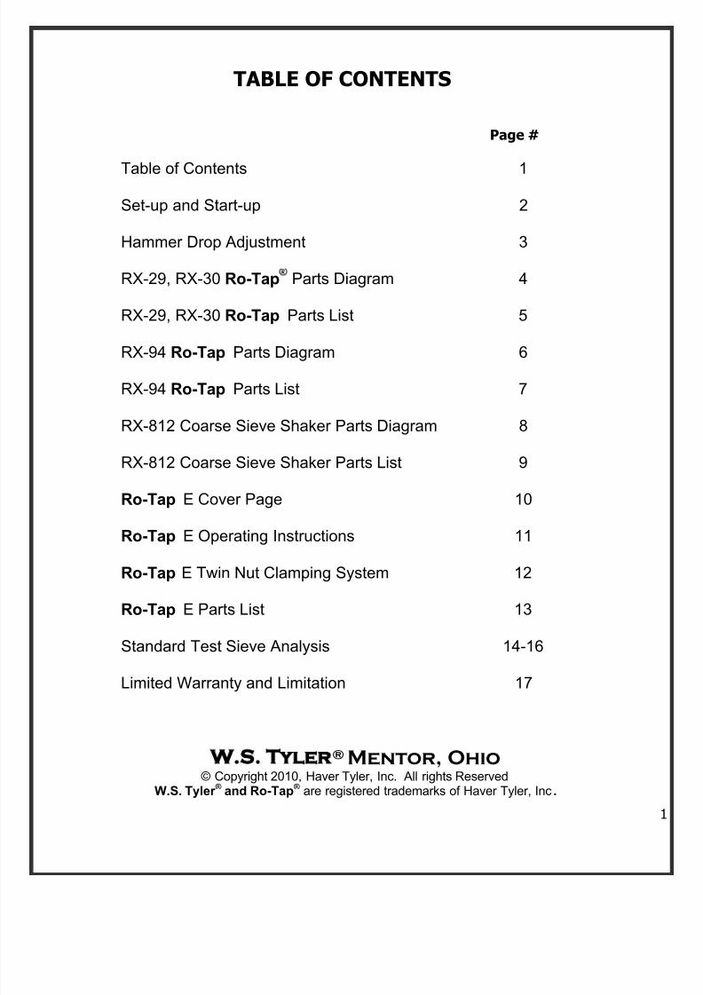
TABLE OF CONTENTS
Page #
Table of Contents 1
Set-up and Start-up 2
Hammer Drop Adjustment 3
RX-29, RX-30 Ro-Tap Parts Diagram 4
RX-29, RX-30 Ro-Tap Parts List 5
RX-94 Ro-Tap Parts Diagram 6
RX-94 Ro-Tap Parts List 7
RX-812 Coarse Sieve Shaker Parts Diagram 8
RX-812 Coarse Sieve Shaker Parts List 9
Ro-Tap E Cover Page 10
Ro-Tap E Operating Instructions 11
Ro-Tap E Twin Nut Clamping System 12
Ro-Tap E Parts List 13
Standard Test Sieve Analysis 14-16
Limited Warranty and Limitation 17
W S Tyler
® Mentor, Ohio© Copyright 2010, Haver Tyler, Inc. All rights Reserved
W.S. Tyler ® and Ro-Tap ® are registered trademarks of Haver Tyler, Inc.
7/18/2019 Operations Manual 2013 Revised
http://slidepdf.com/reader/full/operations-manual-2013-revised 3/19
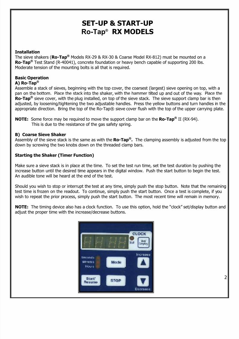
SET-UP & START-UPRo-Tap ® RX MODELS
Installation
The sieve shakers (Ro-Tap
®
Models RX-29 & RX-30 & Coarse Model RX-812) must be mounted on aRo-Tap® Test Stand (R-40041), concrete foundation or heavy bench capable of supporting 200 lbs.Moderate tension of the mounting bolts is all that is required.
Basic Operation A) Ro-Tap® Assemble a stack of sieves, beginning with the top cover, the coarsest (largest) sieve opening on top, with apan on the bottom. Place the stack into the shaker, with the hammer tilted up and out of the way. Place theRo-Tap® sieve cover, with the plug installed, on top of the sieve stack. The sieve support clamp bar is thenadjusted, by loosening/tightening the two adjustable handles. Press the yellow buttons and turn handles in theappropriate direction. Bring the top of the Ro-Tap® sieve cover flush with the top of the upper carrying plate.
NOTE: Some force may be required to move the support clamp bar on the Ro-Tap® II (RX-94).This is due to the resistance of the gas safety spring.
B) Coarse Sieve Shaker Assembly of the sieve stack is the same as with the Ro-Tap®. The clamping assembly is adjusted from the todown by screwing the two knobs down on the threaded clamp bars.
Starting the Shaker (Timer Function)
Make sure a sieve stack is in place at the time. To set the test run time, set the test duration by pushing theincrease button until the desired time appears in the digital window. Push the start button to begin the test.
An audible tone will be heard at the end of the test.
Should you wish to stop or interrupt the test at any time, simply push the stop button. Note that the remainintest time is frozen on the readout. To continue, simply push the start button. Once a test is complete, if youwish to repeat the prior process, simply push the start button. The most recent time will remain in memory.
NOTE: The timing device also has a clock function. To use this option, hold the “clock” set/display button anadjust the proper time with the increase/decrease buttons.
7/18/2019 Operations Manual 2013 Revised
http://slidepdf.com/reader/full/operations-manual-2013-revised 4/19
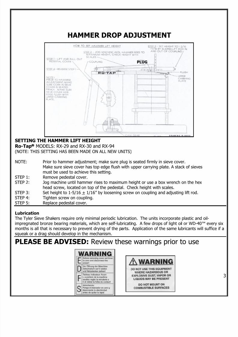
HAMMER DROP ADJUSTMENT
PLUG
SETTING THE HAMMER LIFT HEIGHTRo-Tap® MODELS: RX-29 and RX-30 and RX-94
(NOTE: THIS SETTING HAS BEEN MADE ON ALL NEW UNITS)
NOTE: Prior to hammer adjustment; make sure plug is seated firmly in sieve cover.Make sure sieve cover has top edge flush with upper carrying plate. A stack of sievesmust be used to achieve this setting.
STEP 1: Remove pedestal cover.STEP 2: Jog machine until hammer rises to maximum height or use a box wrench on the hex
head screw, located on top of the pedestal. Check height with scales.STEP 3: Set height to 1-5/16 + 1/16” by loosening screw on coupling and adjusting lift rod.STEP 4: Tighten screw on coupling.STEP 5: Replace pedestal cover.
LubricationThe Tyler Sieve Shakers require only minimal periodic lubrication. The units incorporate plastic and oil-impregnated bronze bearing materials, which are self-lubricating. A few drops of light oil or WD-40™ every sixmonths is all that is necessary to prevent drying of the parts. Application of the same lubricants will suffice if asqueak or a drag should develop in the mechanism.
PLEASE BE ADVISED: Review these warnings prior to use
7/18/2019 Operations Manual 2013 Revised
http://slidepdf.com/reader/full/operations-manual-2013-revised 5/19
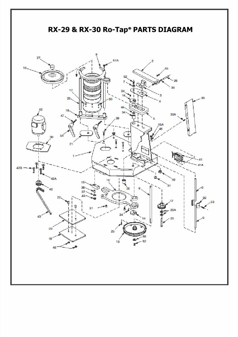
RX-29 & RX-30 Ro-Tap® PARTS DIAGRAM
7/18/2019 Operations Manual 2013 Revised
http://slidepdf.com/reader/full/operations-manual-2013-revised 6/19
RX-29 & RX-30 Ro-Tap® PARTS LIST
ITEM
PART DESCRIPTION QTYREQ’D
ITEM PART DESCRIPTION QTYREQ’D
1 107770 Base 1 41 R-40037 Electronic Timer (230v) 12 R-20029 Hammer 1 41A R-40040 Timer Mounting Clip 2
3 R-20023 Hammer Block 1 42 P-1500-23
Motor-Standard 115/230v 60/50Hz1Phase
1
4 R-30019 Sheet Guard 1 42A ZF10183 3/8-16 x 1” Hex Flange Bolt 4
5 R-30010 Rotating Guard 1 43 R-10058 Timing Belt 1
6 R-10036 Lift Rod 2 44 R-10055 Shim 1
7 R-10038 Upper Main Shaft Washer 1 45 ZZ10068 1//2-13 x 2.50” Long Hex Hd. Bolt 1
8 R-20027 Main Shaft 1 45A ZZ10323 ½ I.D. Lock Washer 1
9 R-30008 Upper Carrying Plate/RX-29 1 1
9a R-30008-1 Upper Carrying Plate (alum) 1 47 R-10079 Clamp Screw 2
9 R-30027 Upper Carrying Plate/RX-30 1 48 ZF10221 3/8” Lock Nut 3
10 R-30009 Lower Carrying Plate 1 49 ZF10222 1/2” Hex Lock Nut 1
12 R-20039 Cam Gear 1 50 ZF10231 10-32x.50” LongFlatHeadSocketCapScrew
3
13 R-30015 Timing Belt Pulley 1 51 ZF10241 3/8-16x.75”LongFlatHeadSocketCapScrew
2
14 R-10034 Eccentric Disc 2 51A ZF10183 3/8-16x1” Hex Flange Bolt 2
15 R-10032 Block 1 52 114162 3/6-16x x 62” Long Hex Head Screw 2
16 R-30007 Sieve Cover (RX-29) 1 53 ZF10251 5/16-24x1.25” LongSocketHeadCapScrew
1
16 R-30011 Sieve Cover (RX-30) 1 54 R-20082 Adj. Handle (Support Bar) 2
17 R-30006 Sieve Support Plate (RX-29) 1 55 ZA10148 #10-24x.25” Socket Hd. Set Screw 1
17 R-30013 Sieve Support Plate (RX-30) 1 56 ZF10271 3/8 I.D. X 1.50” O.D. Fender Washer 1
18 R-30023 Sieve Support Clamp Bar (RX-29) 1 60* R-10018 Timer Cord w/Plug 1
18 R-30022 Sieve Support Clamp Bar (RX-30) 1 61* R-10019 Cable Tie Ml’g 3
19 R-20019 Backup Plate 1 62* R-10112 Straight Connector (APC-050) 2
20 R-20020 Bearing Plate 1 66* 107764 Flexible Conduit 1
21 R-20033 Shield 2 67* R-10076 Wire Clip 1
22 R-10028 Tube Spacer 2 68* ZZ10011 Screw For Wire Clip & Ground Screw 3
23 R-10029 Cam Shoulder Screw 1 69* R-20081 Wrench 123A 106582 I.D. Shim 2
24 R-10042 Main Shaft Key to Eccentric 2
*ITEMS NOT SHOWN*PARTS SOLD AS EACH
25 R-10039 Main Shaft Key-Lower 1
26 R-10035 Hammer Pin 1
27 R-10066 Cork plug 1
28 108184 Name Plate 1
29 R-10033 Tie-Rod 2
30 R-30018 Motor Adapter 1
31 ZA11167 Grommet 2
32 R-10030 Lift Rod Coupling(2.50” Long) 1
33 R-40011 Pedestal Cover 1
33A 8/18 X 75 Self Tapping Screw 1
34 R-10061 Flange Bearing 1
35 R-10062 Bearing 1
36 R-10063 Flange Bearing 237 ZF10168 Thrust Washer 1
38 R-10065 Steel Bushing 1
39 ZF10174 3.8-16 NC X 2.25” Carriage Bolt 3
40 R-10070 Sprocket-14-Teeth (1800 RPM)w/Set ScrewSprocket-17-Teeth (1500 RPM)w/Set Screw
1
1
41 R-40029 Electronic Timer (115v) 1
4
7/18/2019 Operations Manual 2013 Revised
http://slidepdf.com/reader/full/operations-manual-2013-revised 7/19
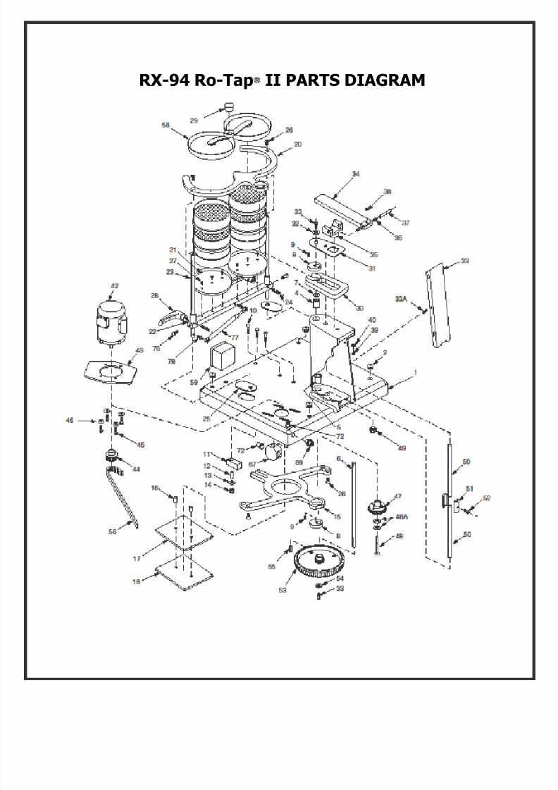
RX-94 Ro-Tap® II PARTS DIAGRAM
7/18/2019 Operations Manual 2013 Revised
http://slidepdf.com/reader/full/operations-manual-2013-revised 8/19
6
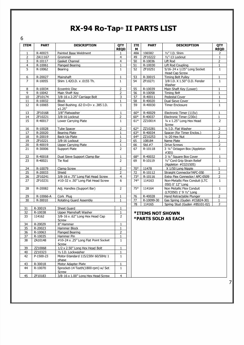
RX-94 Ro-Tap® II PARTS LIST
ITEM PART DESCRIPTION QTYREQD
ITEM
PART DESCRIPTION QTYREQD
1 R-40023 Painted Base Weldment 1 48A 106582 ½” I.D. Shim 2
2 ZA11167 Grommet 4 49 ZF10222 ½” -13 Locknut 1
3 R-10117 Gasket Channel 4 50 R-10036 Lift Rod 24 R-10061 Flanged Bearing 1 51 R-10030 Lift Rod Coupling 1
5 R-10062 Bearing 1 52 ZF10251 5/16-24 x 1/25” Long SocketHead Cap Screw
1
6 R-20027 Mainshaft 1 53 R-30015 Timing Belt Pulley 1
7 R-10055 Shim 1.42O.D. x .0155 Th. 1 54 ZF10271 3/8 I.D. X 1.50” O.D. FenderWasher
1
8 R-10034 Eccentric Disc 2 55 R-10039 Main Shaft Key (Lower) 1
9 R-10042 Main Shaft Key 2 56 R-10058 Timing Belt 1
10 ZF10174 3/8-16 x 2.25” Carriage Bolt 3 57 R-40011 Pedestal Cover 1
11 R-10032 Block 1 58 R-40020 Dual Sieve Cover 1
12 R-10065 Steel Bushing .62 O>D> x .385 I.D.x1.25”
1 59 R-40030 Timer Enclosure 1
13 ZF10168 3/8” Flatwasher 1 60* R-40029 Electronic Timer (115v) 1
14 ZF10221 3/8-16 Locknut 2 60* R-40037 Electronic Timer (230v) 1
15 R-40017 Lower Carrying Plate 1 61* ZZ10014 ¼ x 1.25” Long Hex HeadScrew
2
16 R-10028 Tube Spacer 2 62* ZZ10281 ¼ I.D. Flat Washer 2
17 R-20020 Bearing Plate 1 63* R-40034 Spacer (for Timer Enclos.) 2
18 R-20019 Back-Up Plate 1 64* ZZ10253 ¼-20 Hex Nut 2
19 ZF10221 3/8-16 Lockout 2 65 108184 Name Plate 1
20 R-40019 Upper Carrying Plate 1 66 Std.#7 Drive Screws 2
21 R-30006 Support Plate 2 67 R-10118 3 ¼” Octagon Box (Appleton#30))
1
22 R-40018 Dual Sieve Support Clamp Bar 1 68* R-40032 3 ¼” Square Box Cover 1
23 R-40021 Tie Rod 2 69 R-10119 ½” Cord Grip Strain Relief(Appleton #CG31505)
1
24 R-10079 Clamp Screw 2 70* 11478 X 1/50 Long Nipple 1
25 R-20033 Shield 2 72 R-10112 Straight Connector?APC-050 2
26 ZF10241 3/8-16 x .75” Long Flat Head Screw 4 73* R-10116 Extra Flex Connector/ APC-0509 2
27 ZF10231 #10-32 x .50” Long Flat Head Screw 6 74* 114163 Non-Metallic Flex Conduit (LTC050) 0’ 12” Long
1
28 R-20082 Adj. Handles (Support Bar) 2 75* 114164 Non Metallic Flex Conduit(LTC050) 1’ 9 ½” Long
1
29 R-10066-A Cork Plug 1 76 R-40028 Hand Retractable Plunger 2
30 R-30010 Rotating Guard Assembly 1 77 R-10099-30 Gas Spring (Guden #CG824-30) 1
78 114165 Spring Stud (Guden #BS101-02) 2
31 R-30019 Sheet Guard 1
*ITEMS NOT SHOWN*PARTS SOLD AS EACH
32 R-10038 Upper Mainshaft Washer 1
33 114162 3/8-16 x .62” Long Hex Head CapScrew
2
34 R-20029 8” Hammer 1
35 R-20023 Hammer Block 1
36 R-10063 Flanged Bearing 2
37 R-10035 Hammer Pin 1
38 ZA10148 #10-24 x .25” Long Flat Point SocketScrew 1
39 ZZ10068 1/2 x 2.50” Long Hex Head Bolt 1
40 ZZ10323 ½ I.D. Lockwasher 1
42 P-1500-23 Motor-Standard 115/230V 60/50Hz 1phase
1
43 R-30018 Motor Adapter Plate 1
44 R-10070 Sprocket-14 Teeth(1800 rpm) w/ SetScrew
1
45 ZF10183 3/8-16 x 1.00” Long Hex Head Screw 4

7/18/2019 Operations Manual 2013 Revised
http://slidepdf.com/reader/full/operations-manual-2013-revised 9/19
46 ZF10168 3/8 I.D. Flat Washer 4
47 R-20039 Cam Gear 1
48 R-10029 Cam Shoulder Screw 1
RX-812 COARSE SIEVE SHAKER PARTS DIAGRAM
7/18/2019 Operations Manual 2013 Revised
http://slidepdf.com/reader/full/operations-manual-2013-revised 10/19
8
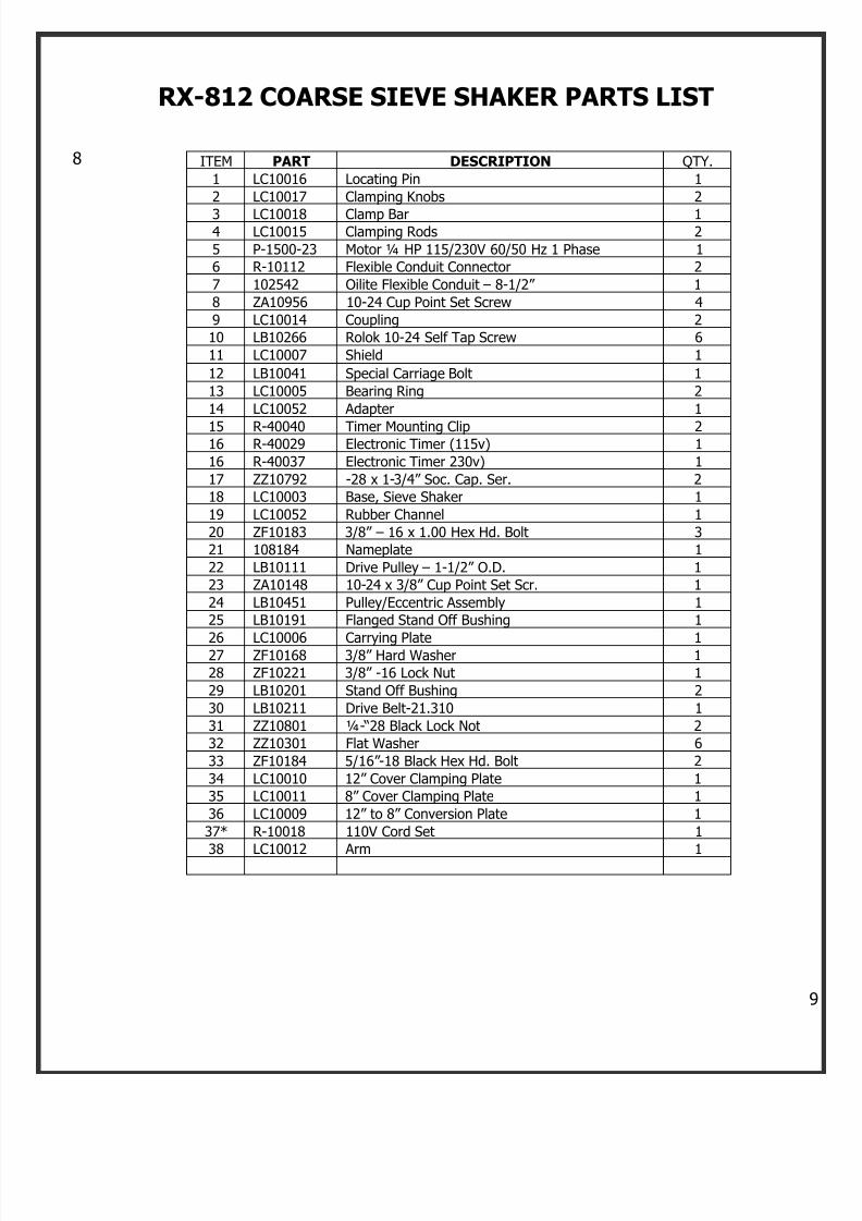
RX-812 COARSE SIEVE SHAKER PARTS LIST
ITEM PART DESCRIPTION QTY.
1 LC10016 Locating Pin 1
2 LC10017 Clamping Knobs 2
3 LC10018 Clamp Bar 14 LC10015 Clamping Rods 2
5 P-1500-23 Motor ¼ HP 115/230V 60/50 Hz 1 Phase 1
6 R-10112 Flexible Conduit Connector 2
7 102542 Oilite Flexible Conduit – 8-1/2” 1
8 ZA10956 10-24 Cup Point Set Screw 4
9 LC10014 Coupling 2
10 LB10266 Rolok 10-24 Self Tap Screw 6
11 LC10007 Shield 1
12 LB10041 Special Carriage Bolt 1
13 LC10005 Bearing Ring 2
14 LC10052 Adapter 1
15 R-40040 Timer Mounting Clip 216 R-40029 Electronic Timer (115v) 1
16 R-40037 Electronic Timer 230v) 1
17 ZZ10792 -28 x 1-3/4” Soc. Cap. Ser. 2
18 LC10003 Base, Sieve Shaker 1
19 LC10052 Rubber Channel 1
20 ZF10183 3/8” – 16 x 1.00 Hex Hd. Bolt 3
21 108184 Nameplate 1
22 LB10111 Drive Pulley – 1-1/2” O.D. 1
23 ZA10148 10-24 x 3/8” Cup Point Set Scr. 1
24 LB10451 Pulley/Eccentric Assembly 1
25 LB10191 Flanged Stand Off Bushing 1
26 LC10006 Carrying Plate 127 ZF10168 3/8” Hard Washer 1
28 ZF10221 3/8” -16 Lock Nut 1
29 LB10201 Stand Off Bushing 2
30 LB10211 Drive Belt-21.310 1
31 ZZ10801 ¼- “28 Black Lock Not 2
32 ZZ10301 Flat Washer 6
33 ZF10184 5/16” -18 Black Hex Hd. Bolt 2
34 LC10010 12” Cover Clamping Plate 1
35 LC10011 8” Cover Clamping Plate 1
36 LC10009 12” to 8” Conversion Plate 1
37* R-10018 110V Cord Set 1
38 LC10012 Arm 1
7/18/2019 Operations Manual 2013 Revised
http://slidepdf.com/reader/full/operations-manual-2013-revised 11/19
1
Ro-Tap® E
Model RX-29-E
7/18/2019 Operations Manual 2013 Revised
http://slidepdf.com/reader/full/operations-manual-2013-revised 12/19
1
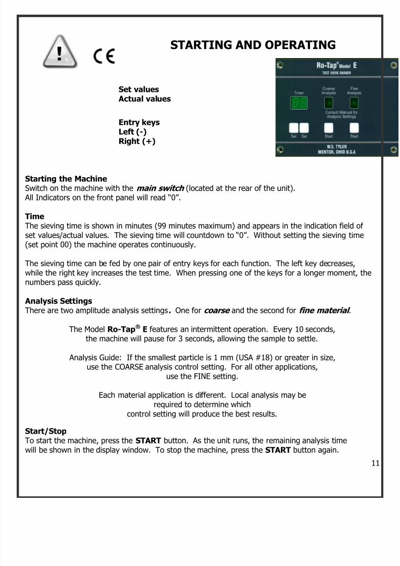
STARTING AND OPERATING
Set values
Actual values
Entry keysLeft (-)Right (+)
Starting the MachineSwitch on the machine with the main switch (located at the rear of the unit).
All Indicators on the front panel will read “0”.
Time The sieving time is shown in minutes (99 minutes maximum) and appears in the indication field ofset values/actual values. The sieving time will countdown to “0”. Without setting the sieving time(set point 00) the machine operates continuously.
The sieving time can be fed by one pair of entry keys for each function. The left key decreases,while the right key increases the test time. When pressing one of the keys for a longer moment, thenumbers pass quickly.
Analysis Settings
There are two amplitude analysis settings. One for coarse and the second for fine material .
The Model Ro-Tap® E features an intermittent operation. Every 10 seconds,the machine will pause for 3 seconds, allowing the sample to settle.
Analysis Guide: If the smallest particle is 1 mm (USA #18) or greater in size,use the COARSE analysis control setting. For all other applications,
use the FINE setting.
Each material application is different. Local analysis may berequired to determine which
control setting will produce the best results.
Start/StopTo start the machine, press the START button. As the unit runs, the remaining analysis timewill be shown in the display window. To stop the machine, press the START button again.
7/18/2019 Operations Manual 2013 Revised
http://slidepdf.com/reader/full/operations-manual-2013-revised 13/19
1
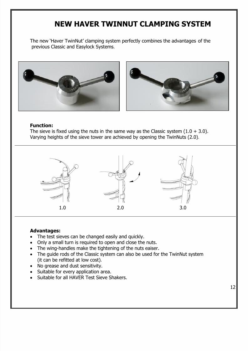
NEW HAVER TWINNUT CLAMPING SYSTEM
The new ‘Haver TwinNut’ clamping system perfectly combines the advantages of theprevious Classic and Easylock Systems.
Function:The sieve is fixed using the nuts in the same way as the Classic system (1.0 + 3.0).
Varying heights of the sieve tower are achieved by opening the TwinNuts (2.0).
1.0 2.0 3.0
Advantages: The test sieves can be changed easily and quickly. Only a small turn is required to open and close the nuts. The wing-handles make the tightening of the nuts eaiser.
The guide rods of the Classic system can also be used for the TwinNut system(it can be refitted at low cost).
No grease and dust sensitivity. Suitable for every application area. Suitable for all HAVER Test Sieve Shakers.
7/18/2019 Operations Manual 2013 Revised
http://slidepdf.com/reader/full/operations-manual-2013-revised 14/19
1
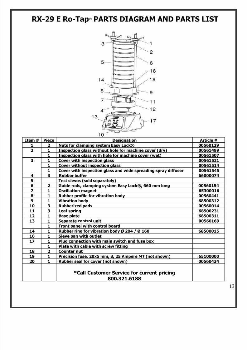
RX-29 E Ro-Tap® PARTS DIAGRAM AND PARTS LIST
Item # Piece Designation Article #
1 2 Nuts for clamping system Easy Lock® 00560129
2 1 Inspection glass without hole for machine cover (dry) 00561499
1 Inspection glass with hole for machine cover (wet) 00561507
3 1 Cover with inspection glass 00561521
1 Cover without inspection glass 00561514
1 Cover with inspection glass and wide spreading spray diffuser 00561545
4 3 Rubber buffer 66000074
5 Test sieves (sold separately)
6 2 Guide rods, clamping system Easy Lock®, 660 mm long 00560154
7 1 Oscillation magnet 65300016
8 1 Rubber profile for vibration body 00560441
9 1 Vibration body 68500312
10 3 Rubberized pads 00560014
11 3 Leaf spring 68500231
12 1 Base plate 68500311
13 1 Separate control unit 00560169
1 Front panel with control board
14 1 Rubber ring for vibration body Ø 204 / Ø 160 68500015
16 1 Sieve pan with outlet
17 1 Plug connection with main switch and fuse box
1 Plate with cable with screw fitting18 2 Counter nut
19 1 Precision fuse, 20x5 mm, 3, 25 Ampere MT (not shown) 65100000
20 1 Rubber seal for cover (not shown) 00560434
*Call Customer Service for current pricing800.321.6188
7/18/2019 Operations Manual 2013 Revised
http://slidepdf.com/reader/full/operations-manual-2013-revised 15/19
1
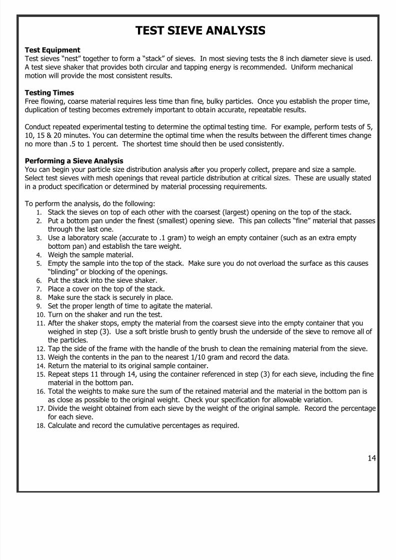
TEST SIEVE ANALYSIS
Test EquipmentTest sieves “nest” together to form a “stack” of sieves. In most sieving tests the 8 inch diameter sieve is used A test sieve shaker that provides both circular and tapping energy is recommended. Uniform mechanicalmotion will provide the most consistent results.
Testing TimesFree flowing, coarse material requires less time than fine, bulky particles. Once you establish the proper time,duplication of testing becomes extremely important to obtain accurate, repeatable results.
Conduct repeated experimental testing to determine the optimal testing time. For example, perform tests of 510, 15 & 20 minutes. You can determine the optimal time when the results between the different times changeno more than .5 to 1 percent. The shortest time should then be used consistently.
Performing a Sieve Analysis You can begin your particle size distribution analysis after you properly collect, prepare and size a sample.Select test sieves with mesh openings that reveal particle distribution at critical sizes. These are usually statedin a product specification or determined by material processing requirements.
To perform the analysis, do the following:1. Stack the sieves on top of each other with the coarsest (largest) opening on the top of the stack.2. Put a bottom pan under the finest (smallest) opening sieve. This pan collects “fine” material that passe
through the last one.
3. Use a laboratory scale (accurate to .1 gram) to weigh an empty container (such as an extra emptybottom pan) and establish the tare weight.
4. Weigh the sample material.5. Empty the sample into the top of the stack. Make sure you do not overload the surface as this causes
“blinding” or blocking of the openings.
6. Put the stack into the sieve shaker.
7. Place a cover on the top of the stack.8. Make sure the stack is securely in place.9. Set the proper length of time to agitate the material.10. Turn on the shaker and run the test.11. After the shaker stops, empty the material from the coarsest sieve into the empty container that you
weighed in step (3). Use a soft bristle brush to gently brush the underside of the sieve to remove all ofthe particles.
12. Tap the side of the frame with the handle of the brush to clean the remaining material from the sieve.
13. Weigh the contents in the pan to the nearest 1/10 gram and record the data.
14. Return the material to its original sample container.15. Repeat steps 11 through 14, using the container referenced in step (3) for each sieve, including the fine
material in the bottom pan.
16. Total the weights to make sure the sum of the retained material and the material in the bottom pan isas close as possible to the original weight. Check your specification for allowable variation.
17. Divide the weight obtained from each sieve by the weight of the original sample. Record the percentagfor each sieve.
18. Calculate and record the cumulative percentages as required.
7/18/2019 Operations Manual 2013 Revised
http://slidepdf.com/reader/full/operations-manual-2013-revised 16/19
1
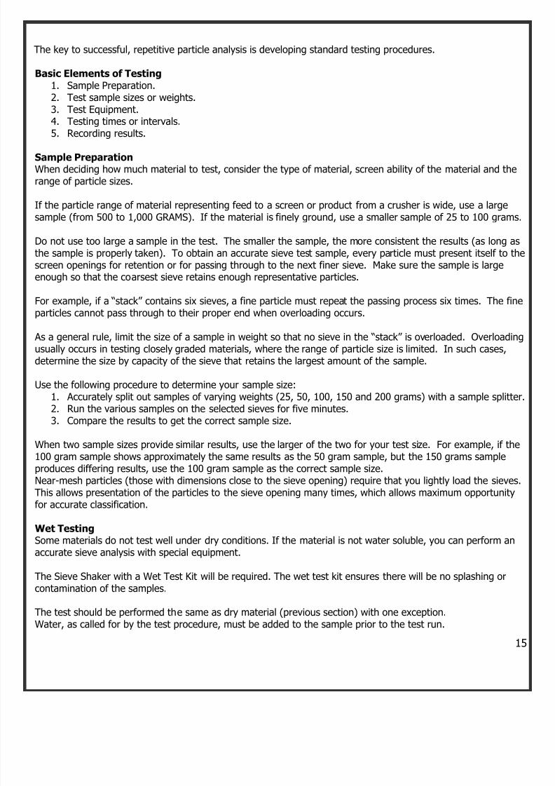
The key to successful, repetitive particle analysis is developing standard testing procedures.
Basic Elements of Testing1. Sample Preparation.2. Test sample sizes or weights.3. Test Equipment.4. Testing times or intervals.
5. Recording results.
Sample PreparationWhen deciding how much material to test, consider the type of material, screen ability of the material and therange of particle sizes.
If the particle range of material representing feed to a screen or product from a crusher is wide, use a largesample (from 500 to 1,000 GRAMS). If the material is finely ground, use a smaller sample of 25 to 100 grams
Do not use too large a sample in the test. The smaller the sample, the more consistent the results (as long asthe sample is properly taken). To obtain an accurate sieve test sample, every particle must present itself to thscreen openings for retention or for passing through to the next finer sieve. Make sure the sample is large
enough so that the coarsest sieve retains enough representative particles.
For example, if a “stack” contains six sieves, a fine particle must repeat the passing process six times. The fineparticles cannot pass through to their proper end when overloading occurs.
As a general rule, limit the size of a sample in weight so that no sieve in the “stack” is overloaded. Overloadinusually occurs in testing closely graded materials, where the range of particle size is limited. In such cases,determine the size by capacity of the sieve that retains the largest amount of the sample.
Use the following procedure to determine your sample size:1. Accurately split out samples of varying weights (25, 50, 100, 150 and 200 grams) with a sample splitter
2. Run the various samples on the selected sieves for five minutes.3. Compare the results to get the correct sample size.
When two sample sizes provide similar results, use the larger of the two for your test size. For example, if the100 gram sample shows approximately the same results as the 50 gram sample, but the 150 grams sampleproduces differing results, use the 100 gram sample as the correct sample size.Near-mesh particles (those with dimensions close to the sieve opening) require that you lightly load the sievesThis allows presentation of the particles to the sieve opening many times, which allows maximum opportunityfor accurate classification.
Wet TestingSome materials do not test well under dry conditions. If the material is not water soluble, you can perform an
accurate sieve analysis with special equipment.
The Sieve Shaker with a Wet Test Kit will be required. The wet test kit ensures there will be no splashing orcontamination of the samples.
The test should be performed the same as dry material (previous section) with one exception.Water, as called for by the test procedure, must be added to the sample prior to the test run.
7/18/2019 Operations Manual 2013 Revised
http://slidepdf.com/reader/full/operations-manual-2013-revised 17/19
1
Static ElectricitySome materials generate static electricity during the dry sieving process. When particles “charge” themselvesas they come in contact with other particles, they stick to the metal frame and cloth of the sieve.
This prevents you from obtaining accurate results.
As a suggestion: Add a small amount of talc, activated charcoal, powdered magnesium carbonate or burgess clay to the
sample material. For a 100 gram sample add approximately 1 gram of chemical. Mix thoroughly to completely coat the particle surfaces. Perform the sieve test.
This method may not eliminate static electricity entirely; however, the effect should be significantlyreduced and will not affect your test results.
7/18/2019 Operations Manual 2013 Revised
http://slidepdf.com/reader/full/operations-manual-2013-revised 18/19
1
W.S. TYLER ™ INDUSTRIAL GROUP
W.S. TYLER8570 Tyler Blvd.Mentor, Ohio 44060ISO 9001:2008 REGISTERED
800.321.6188 toll free
440.974.1047 local440.974.0921 faxe-mail: [email protected] Web: www.wstyler.com
HAVER & BOECKEREnnigerioher Str. 64D-59302 Oelde, Germany49-25522-30-0 phone49-2522-30404 faxwww.haverboecker.com
Ro-Tap® Accessories also available:
Ro-Tap® Maintenance Kits
Ro-Tap®
Test Stand
Ro-Tap® Sound Enclosure
Wet Test Kits
LIMITED WARRANTY AND LIMITATIONW.S. Tyler™ Industrial Group, Mentor, OH
W.S. Tyler warrants, commencing with the date of the first use and for a period of twelve (12) months thereafter, itsIndustrial Group Products to be free from defects in workmanship and materials. This warranty applies to the firstpurchaser.
If, within such warranty period, any new products shall be proved to W.S. Tyler’s satisfaction to be defective, it shall berepaired, or at W.S. Tyler’s option, replaced F.O.B. factory, without charges.
W.S. Tyler’s obligation hereunder shall be confined to such repair or replacement and does not include any charges,direct or indirect, for shipping, removing, or installing defective products.
No warranty shall apply to used products nor to products which have been furnished, repaired or altered by others soas, in W.S. Tyler’s judgment, to affect the same adversely or which shall have been subject to negligence, accident orimproper care, installation, maintenance, storage or other than normal use or service.
W.S. TYLER’S EXPRESSED WARRANTY AND THE REMEDIES SET FORTH HEREIN ARE EXCLUSIVE AND NOOTHER WARRANTIES, GUARANTEES OR REMEDIES OF ANY KIND WHETHER STATUTOR, WRITTEN, ORAL,EXPRESSED, OR IMPLIED, INCLUDING THE WARRANTIES OF MERCHANTABILITY AND/OR FITNESS FOR APARTICULAR PURPOSE, SHALL APPLY.
This warranty gives you specific legal rights, and you may also have other rights that vary from state to state. Theliability of W.S. Tyler arising out of the manufacture, sale, delivery, use or resale of the product, whether based onwarranty, contract, negligence, tort, strict liability or otherwise, and whether for direct, indirect, special, consequential,
exemplary, punitive or other damage, shall not exceed the cost of replacement of the product. Upon the expiration ofthe warranty, all such liability shall terminate.
IN NO EVENT SHALL W.S. TYLER BE LIABLE FOR LOSS OF PROFITS, DIRECT, INDIRECT, INCIDENTAL,SPECIAL OR CONSEQUENTIAL DAMAGES, WHETHER ATTRIBUTABLE TO DEFECTS IN MATERIALFURNISHED, PRODUCT IDENTIFICATION, DELAYS IN DELIVERY, OR OTHERWISE. Some states do not allow theexclusion or limitation of incidental or consequential damages, so the above limitation may not apply to you.
© Copyright 2011, W.S. Tyler. All Rights Reserved.

7/18/2019 Operations Manual 2013 Revised
http://slidepdf.com/reader/full/operations-manual-2013-revised 19/19
1