Embed Size (px)
Citation preview
TM 10-3930-664-10
Technical Manual
OPERATOR’S MANUAL
TRUCK, FORKLIFT, 4000 LB. CAPACITYROUGH TERRAIN, DED, PNEUMATIC TIRE
ARMY MODEL MHE-270 (WITHOUT CAB) ARMY MODEL MHE-271 (WITH CAB)(NSN 3930-01-330-8907) (NSN 3930-01-330-8906 )
Approved for public release: distribution is unlimited.
HEADQUARTERS, DEPARTMENT OF THE ARMY JULY 1994
PRINCIPLES OF 1-8OPERATIONS
INTRODUCTION 1-1
OPERATING 2-1INSTRUCTIONS
PMCS 2-15
OPERATION UNDER 2-25USUAL CONDITIONS
OPERATION UNDER 2-26UNUSUAL CONDITIONS
OPERATOR MAINTENANCEINSTRUCTIONS 3-1
TROUBLESHOOTING 3-1PROCEDURES
MAINTENANCE 3-14PROCEDURES
INDEX Index-1
TM 10-3930-664-10SAFETY SUMMARY
WARNING
CARBON MONOXIDE (EXHAUST GAS) CAN KILL YOU
Carbon monoxide is colorless, odorless, DEADLY POISONOUS gas which, when breathed, deprives the body of oxygenand causes SUFFOCATION. Breathing air with carbon monoxide produces symptoms of headache, dizziness, loss ofmuscular control, a sleepy feeling, and coma. Permanent BRAIN DAMAGE or DEATH can result from severe exposure.
Carbon monoxide occurs in the exhaust fumes of fuel-burning and internal-combustion engines, and becomesDANGEROUSLY CONCENTRATED where fresh air is not moving. The following precautions MUST be followed to makesure personnel are safe whenever the engine is operated for any purpose.
- DO NOT operate engine in a closed place unless that place has a lot of fresh moving air.
- BE ALERT at all times during vehicle operation for exhaust odors and exposure symptoms. If either are present,IMMEDIATELY VENTILATE the area. If symptoms persist, remove affected personnel from the work area and treat asfollows: expose to fresh air; keep warm; DO NOT PERMIT PHYSICAL EXERCISE; if necessary, give artificial respirationas described in FM 21-11 and get medical attention.
- BE AWARE; neither the gas particulate filter unit nor the field protection mask for nuclear-biological-chemical protectionwill protect you from carbon monoxide poisoning.
THE BEST DEFENSE AGAINST CARBON MONOXIDE POISONING ISGOOD VENTILATION
WARNING
Fuel is very flammable and can explode easily. To avoid serious injury or death: when refueling, stop the vehicle, shutdown the engine, and apply the parking brake. Make sure no flame is near the area. Never smoke. Never add fuel withengine running. After fuel is added, securely close the reservoir cap; a loose cap can cause a fuel leak or be a fire hazard.Before starting the vehicle, check that no fuel is spilled on or around the vehicle.
WARNING
Fuel and oil are slippery and can cause falls. To avoid injury, wipe up spilled fuel or oil with rags.
WARNING
Be sure your seat belt is fastened before operating the vehicle. Avoid sudden stops and operate at a safe speed.
a
TM 10-3930-664-10SAFETY SUMMARY
WARNING
Don’t remove the radiator cap when the engine is hot; hot steaming gases can escape and bum you.
Use extreme care when removing the radiator pressure cap. The sudden release of pressure can cause a steam flashwhich could seriously injure you. Slowly loosen cap to the first stop to relieve pressure before removing cap completely.After use, tighten cap securely.
Use a clean thick waste cloth or like to remove the cap. Avoid using gloves, because you could be burned if hot watersoaked through them.
WARNING
High pressure hydraulics (oil under 2350 psi pressure) operate this equipment. A high pressure oil stream can pierce thebody and cause severe injury.
WARNING
High noise levels of 85db(A) or greater are present within 30 feet of this vehicle when the engine is running. Hearingprotection is required for the operator. Hearing protection is also required for all personnel working in and around thisvehicle while the engine is running.
WARNING
TOXIC AND FLAMMABLE
Starting fluid is toxic and highly flammable. Container is pressurized. NEVER heat container and NEVER dischargestarting fluid in confined areas or near an open flame. Failure to comply can result in severe injury.
WARNING
Dry cleaning solvent P-D-680 is toxic and flammable. Wear protective goggles and gloves and use only in a well ventilatedarea. Avoid contact with skin, eyes, and clothes and don’t breath vapors. Do not use near open flame or excessive heat.The flash point is 100°F - 138°F (38°C - 50°C). If you become dizzy while using cleaning solvent, get fresh air immediatelyand get medical aid. If contact with eyes is made, wash your eyes with water and get medical aid immediately.
WARNING
Use caution when inflating tires. Make sure tire is properly seated on rim before inflating. An improperly seated tire canburst with explosive force. Failure to comply can cause DEATH or serious injury.
WARNING
Compressed air used for cleaning purposes will not exceed 30 psi. Use only with effective chip guarding and personalprotective equipment (goggles/shield, gloves, etc.)
b
TM 10-3930-664-10
WARNING
NBC contaminated air filters must be handled and disposed of only by authorized and trained personnel. The unitcommander or senior officer in charge of maintenance personnel must ensure that prescribed protective clothing (FM 3-4)is used, and prescribed safety measures and decontamination procedures (FM 3-5) are followed. The local unit SOP isresponsible for final disposal of contaminated air filters. Failure to comply may cause severe injury or death.
WARNING
When traveling over rough terrain, soft ground, or wet/icy surfaces, slow down and shift to a lower gear. When driving ona floor, dock or bridge, be sure that the combined weights of the machine and load do not exceed the safe limit. Check forsufficient overhead clearance.
WARNING
Keep vehicle away from high voltage power lines. If power line contacts vehicle, vehicle is electrically charged; do nottouch any item not on the vehicle (not grounded) or attempt to leave the vehicle. Failure to comply may result in severeinjury or death.
WARNING
When hooking or unhooking the towbar lunette from a disabled vehicle, set the parking brake or chock the wheels of thedisabled vehicle before hooking or unhooking the towbar. Otherwise, disabled vehicle may move, causing injury, death ordamage.
WARNING
Always operate the vehicle carefully and at a safe speed. Know the rated capacity of the vehicle and do not overload it.Avoid sudden stops to prevent the load from sliding forward and off the forks. NEVER tilt the mast assembly forwardbeyond the vertical position except to deposit the load on a stack.
c/(d blank)
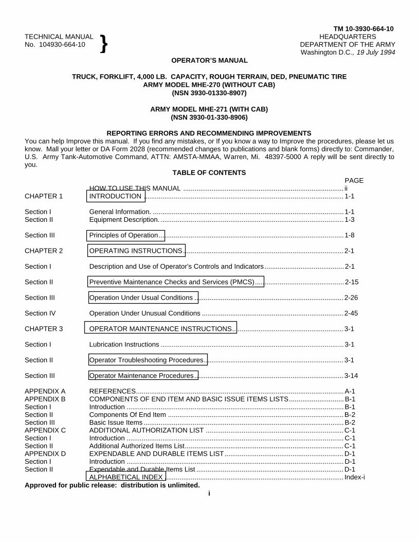
TM 10-3930-664-10TECHNICAL MANUAL HEADQUARTERSNo. 104930-664-10 DEPARTMENT OF THE ARMY
Washington D.C., 19 July 1994OPERATOR’S MANUAL
TRUCK, FORKLIFT, 4,000 LB. CAPACITY, ROUGH TERRAIN, DED, PNEUMATIC TIREARMY MODEL MHE-270 (WITHOUT CAB)
(NSN 3930-01330-8907)
ARMY MODEL MHE-271 (WITH CAB)(NSN 3930-01-330-8906)
REPORTING ERRORS AND RECOMMENDING IMPROVEMENTSYou can help Improve this manual. If you find any mistakes, or If you know a way to Improve the procedures, please let usknow. Mall your letter or DA Form 2028 (recommended changes to publications and blank forms) directly to: Commander,U.S. Army Tank-Automotive Command, ATTN: AMSTA-MMAA, Warren, Mi. 48397-5000 A reply will be sent directly toyou.
TABLE OF CONTENTSPAGE
HOW TO USE THIS MANUAL ..................................................................................... iiCHAPTER 1 INTRODUCTION .......................................................................................................... 1-1
Section I General Information. ..................................................................................................... 1-1Section II Equipment Description. ................................................................................................. 1-3
Section III Principles of Operation.................................................................................................. 1-8
CHAPTER 2 OPERATING INSTRUCTIONS..................................................................................... 2-1
Section I Description and Use of Operator’s Controls and Indicators .......................................... 2-1
Section II Preventive Maintenance Checks and Services (PMCS)............................................... 2-15
Section III Operation Under Usual Conditions ............................................................................... 2-26
Section IV Operation Under Unusual Conditions ........................................................................... 2-45
CHAPTER 3 OPERATOR MAINTENANCE INSTRUCTIONS........................................................... 3-1
Section I Lubrication Instructions ................................................................................................. 3-1
Section II Operator Troubleshooting Procedures.......................................................................... 3-1
Section III Operator Maintenance Procedures ............................................................................... 3-14
APPENDIX A REFERENCES.............................................................................................................. A-1APPENDIX B COMPONENTS OF END ITEM AND BASIC ISSUE ITEMS LISTS............................. B-1Section I Introduction ................................................................................................................... B-1Section II Components Of End Item ............................................................................................. B-2Section III Basic Issue Items .......................................................................................................... B-2APPENDIX C ADDITIONAL AUTHORIZATION LIST ......................................................................... C-1Section I Introduction ................................................................................................................... C-1Section II Additional Authorized Items List.................................................................................... C-1APPENDIX D EXPENDABLE AND DURABLE ITEMS LIST............................................................... D-1Section I Introduction ................................................................................................................... D-1Section II Expendable and Durable Items List .............................................................................. D-1
ALPHABETICAL INDEX ............................................................................................... Index-iApproved for public release: distribution is unlimited.
i
}
TM 10-3930-664-10
HOW TO USE THIS MANUAL
This manual (TM 10-3930-664-10) contains information which you, the operator, will need to properly operate and maintainthe 4000-lb. Rough Terrain Forklift Truck (4KRTFL). This manual is divided into 3 chapters and 4 appendixes with asubject index located after the last appendix. Chapters are divided into sections and sections are further divided intoparagraphs.
BEFORE YOU START
o Read and understand all of the warnings in the front of this manual.
o Read Chapter 1 for standard data found in all TMs. Chapter 1 will also help you to become familiar with thecapabilities, features and operating principles of the 4KRTFL. All right and left indications noted in this manual areto be taken as viewed from the operator’s seat.
o Read Chapter 2 to become familiar with the operator’s controls and indicators, and to learn the proper proceduresfor safe operation of the forklift truck in a variety of conditions. Chapter 2 also contains detailed information aboutyour PMCS responsibilities.
o Read Chapter 3 to become familiar with troubleshooting procedures which will help you isolate and deal withproblems which occur. Chapter 3 also identifies and describes maintenance tasks you are permitted to do.
FEATURES OF THIS MANUAL
o A front cover index of those parts of the manual you will use most often.
o Bleeder edges (a black box) on the first page of each part of the manual in line with the bleeder edge of that samepart on the front cover index for quick access to the part you need.
o A table of contents in the front of the manual for locating any chapter, section or appendix. For quick reference,the titles of those parts of the manual included in the front cover index are identified by a box around the title.
o An index in the back of the manual which lists all subjects in the manual in alphabetical order so that you canquickly locate the information you need.
o WARNINGS, CAUTIONS and NOTES are used to emphasize important information you need to ensure yoursafety and prevent damage to the forklift truck.
ii
TM 10-3930-664-10
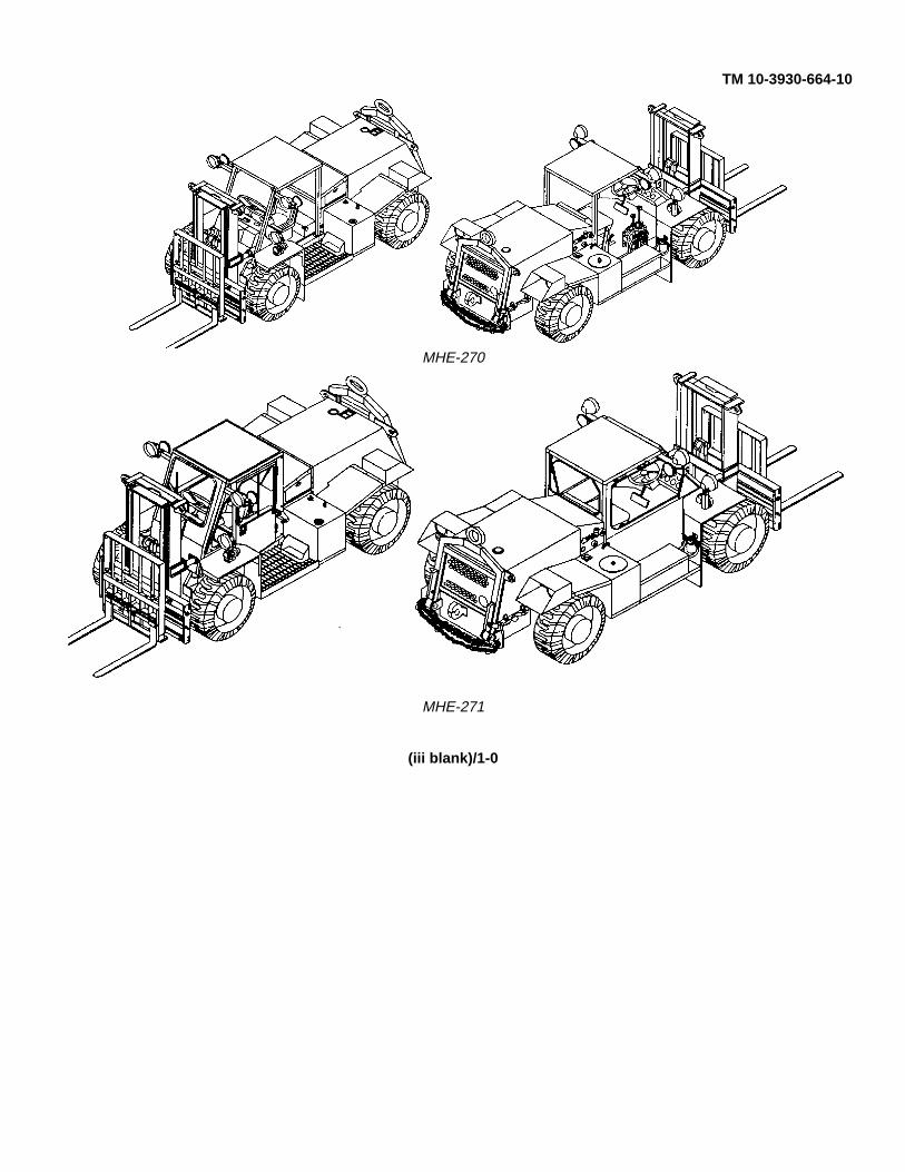
MHE-270
MHE-271
(iii blank)/1-0
TM 10-3930-664-10
CHAPTER 1
INTRODUCTION
SECTION I. General Information
1-1. SCOPE
a. Type of Manual. This manual contains operating, preventive maintenance, troubleshooting and maintenanceinstructions for the 4KRTFL.
b. Equipment Name and Model Numbers. Truck, Forklift, 4000 Pound Capacity, Rough Terrain, Diesel-Engine-Driven, Pneumatic Tire, Army Models MHE-270 (without cab) and MHE-271 (with cab).
c. Purpose of Equipment. The 4KRTFL is designed to handle, transport, and stack materials in various types ofterrain. It is also used to load or unload transport vehicles and containers.
d. Special Limitations on Equipment. The 4KRTFL has no special limitations. Normal limitations such as travelspeed, lift capacity, etc. are given in paragraph 1-12.
1-2. MAINTENANCE FORMS AND PROCEDURES
Department of the Army forms and procedures used for equipment maintenance will be those prescribed by DA Pam 738-750 C The Army Maintenance Management System (TAMMS) (Maintenance Management UPDATE).
1-3. CORROSION PREVENTION AND CONTROL (CPC)
a. Corrosion Prevention and Control (CPC) of Army material is a continuing concern. It is important that anycorrosion problems with this 4KRTFL be detected and reported so that the problem can be corrected and improvementscan be made to prevent the problem in future vehicles or equipment.
b. While corrosion is typically associated with rusting of metals, it can also include deterioration of other materials,such as rubber and plastic. Unusual cracking, softening, swelling, or breaking of these materials may be a corrosionproblem.
c. If a corrosion problem is identified it can be reported using Standard Form 368, Product Quality DeficiencyReport. Use of key words such as "corrosion", "rust", "deterioration", or "cracking" will ensure that the information isidentified as a CPC problem. The form should be submitted to the address specified in DA Pam 738-750.
1-4. DESTRUCTION OF ARMY MATERIAL TO PREVENT ENEMY USE
For destruction of the 4KRTFL to prevent enemy use, refer to TM 750-244-6, Procedures for Destruction of Tank-Automotive Equipment to Prevent Enemy Use.
1-5. REPORTING EQUIPMENT IMPROVEMENT RECOMMENDATION (EIR)
If your 4KRTFL needs improvement, let us know. Send us an EIR. You, the user, are the only one who can tell us whatyou don’t like about your equipment. Let us know why you don’t like the design or performance. Put it on an SF 368(Product Quality Deficiency Report). Mail it to us at U.S. Army Tank-Automotive Command, Attn: AMSTA-QRT, Warren,MI 48397-5000. We will send you a reply.
1-6. WARRANTY INFORMATION
For information concerning warranty of the 4KRTFL refer to Warranty Technical Bulletin, TB 10-3930-664-14.
1-1
TM 10-3930-664-10
1-7. LIST OF ABBREVIATIONS
This list consists of special or unique abbreviations, acronyms, or descriptors not contained in MIL-STD-12.
Abbreviation Description4KRTFL 4000 Pound Rough Terrain Forklift
ROPS Roll Over Protective Structure
FOPS Falling Object Protective Structure
1-8. METRIC UNITS
The 4KRTFL described herein contains metric components and requires metric common or special tools; therefore, metricunits in addition to English units will be used throughout this publication.
1-2
TM 10-3930-664-10
SECTION II. Equipment Description
1-9. EQUIPMENT CHARACTERISTICS, CAPABILITIES AND FEATURES
a. Purpose, The 4KRTFL is designed to handle, transport, and stack materials in various types of terrain. It isalso used to load or unload transport vehicles and containers.
b. Characteristics and Capabilities.
(1) Operates over rough terrain.
(2) Powered by a diesel engine.
(3) Provides power assisted steering.
(4) Lifts loads of 4000 pounds at 24 inch (61 cm) load center to a height of 120 inches (305 cm).
(5) Forks can be shifted left or right up to 22 inches (56 cm).
(6) Forks can be rotated clockwise or counterclockwise up to 10 degrees.
(7) Forks can be tilted forward up to 10 degrees or rearward up to 20 degrees.
(8) Can ford in up to 20 inches (51 cm) of water.
(9) Can tow other vehicles.
c. Features.
(1) Three speed ranges in both forward and reverse.
(2) Declutching of transmission for inching or neutralizing the transmission.
(3) Differential of front axle can be locked to prevent loss of traction.
(4) Automatic actuation of the parking brake upon loss of power.
(5) Three modes of steering; two wheel, four wheel, or crab wheel.
1-3
TM 10-3930-664-10
1-10. LOCATION AND DESCRIPTION OF MAJOR COMPONENTS
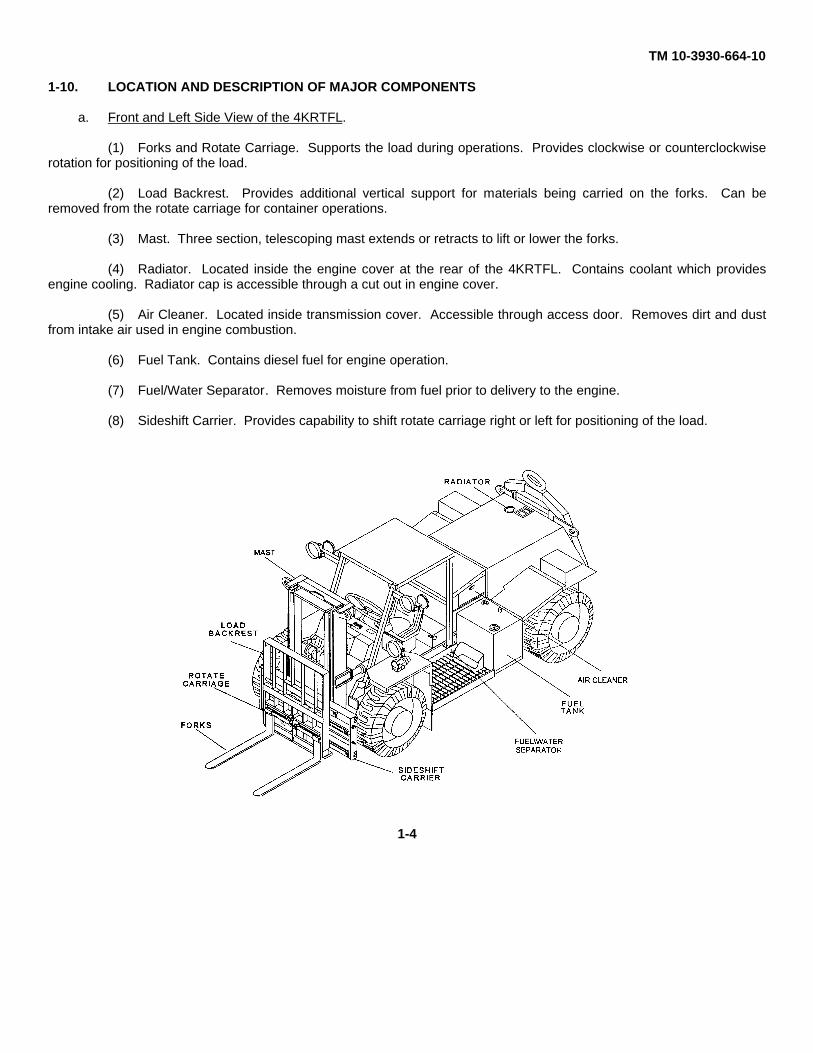
a. Front and Left Side View of the 4KRTFL.
(1) Forks and Rotate Carriage. Supports the load during operations. Provides clockwise or counterclockwiserotation for positioning of the load.
(2) Load Backrest. Provides additional vertical support for materials being carried on the forks. Can beremoved from the rotate carriage for container operations.
(3) Mast. Three section, telescoping mast extends or retracts to lift or lower the forks.
(4) Radiator. Located inside the engine cover at the rear of the 4KRTFL. Contains coolant which providesengine cooling. Radiator cap is accessible through a cut out in engine cover.
(5) Air Cleaner. Located inside transmission cover. Accessible through access door. Removes dirt and dustfrom intake air used in engine combustion.
(6) Fuel Tank. Contains diesel fuel for engine operation.
(7) Fuel/Water Separator. Removes moisture from fuel prior to delivery to the engine.
(8) Sideshift Carrier. Provides capability to shift rotate carriage right or left for positioning of the load.
1-4
TM 10-3930-664-10
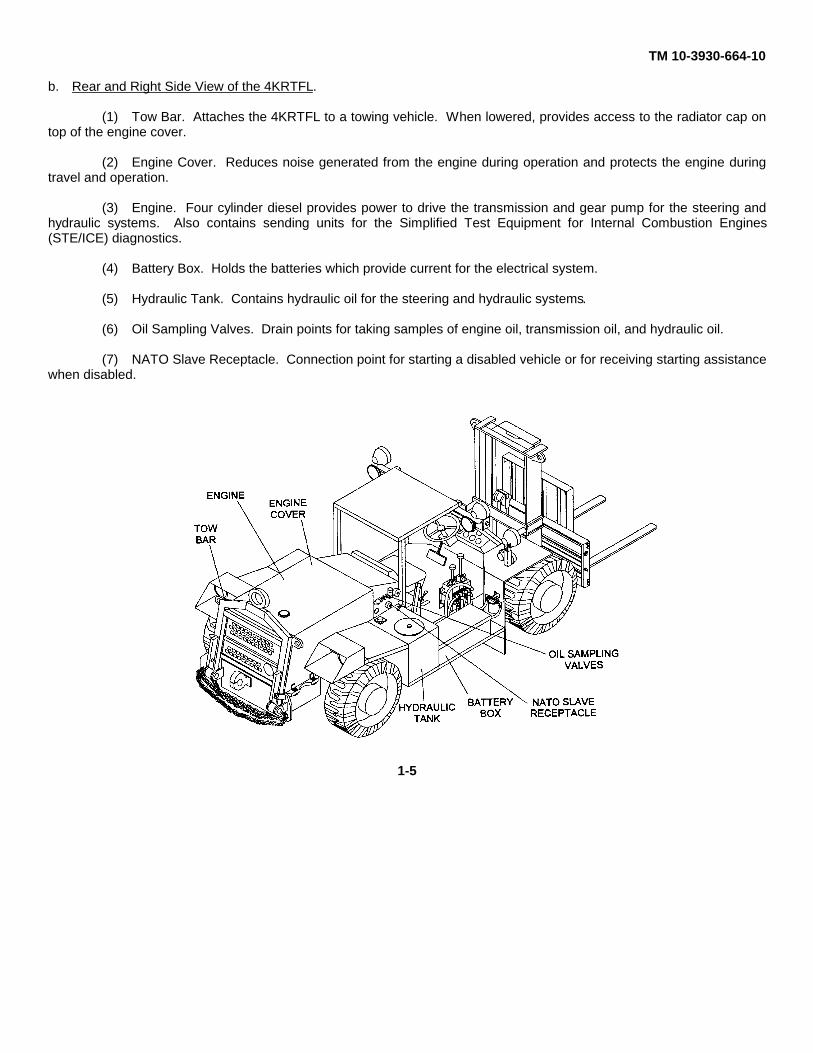
b. Rear and Right Side View of the 4KRTFL.
(1) Tow Bar. Attaches the 4KRTFL to a towing vehicle. When lowered, provides access to the radiator cap ontop of the engine cover.
(2) Engine Cover. Reduces noise generated from the engine during operation and protects the engine duringtravel and operation.
(3) Engine. Four cylinder diesel provides power to drive the transmission and gear pump for the steering andhydraulic systems. Also contains sending units for the Simplified Test Equipment for Internal Combustion Engines(STE/ICE) diagnostics.
(4) Battery Box. Holds the batteries which provide current for the electrical system.
(5) Hydraulic Tank. Contains hydraulic oil for the steering and hydraulic systems.
(6) Oil Sampling Valves. Drain points for taking samples of engine oil, transmission oil, and hydraulic oil.
(7) NATO Slave Receptacle. Connection point for starting a disabled vehicle or for receiving starting assistancewhen disabled.
1-5
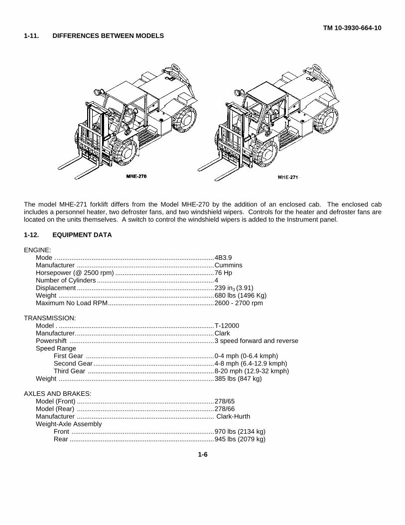
TM 10-3930-664-101-11. DIFFERENCES BETWEEN MODELS
The model MHE-271 forklift differs from the Model MHE-270 by the addition of an enclosed cab. The enclosed cabincludes a personnel heater, two defroster fans, and two windshield wipers. Controls for the heater and defroster fans arelocated on the units themselves. A switch to control the windshield wipers is added to the Instrument panel.
1-12. EQUIPMENT DATA
ENGINE:Mode . ......................................................................................4B3.9Manufacturer ...........................................................................CumminsHorsepower (@ 2500 rpm) ......................................................76 HpNumber of Cylinders ................................................................4Displacement ...........................................................................239 in3 (3.91)Weight .....................................................................................680 lbs (1496 Kg)Maximum No Load RPM..........................................................2600 - 2700 rpm
TRANSMISSION:Model . .....................................................................................T-12000Manufacturer............................................................................ClarkPowershift ...............................................................................3 speed forward and reverseSpeed Range
First Gear ......................................................................0-4 mph (0-6.4 kmph)Second Gear ..................................................................4-8 mph (6.4-12.9 kmph)Third Gear .....................................................................8-20 mph (12.9-32 kmph)
Weight .....................................................................................385 lbs (847 kg)
AXLES AND BRAKES:Model (Front) ...........................................................................278/65Model (Rear) ...........................................................................278/66Manufacturer ........................................................................... Clark-HurthWeight-Axle Assembly
Front ..............................................................................970 lbs (2134 kg)Rear ...............................................................................945 lbs (2079 kg)
1-6
TM 10-3930-664-10
DIMENSIONS AND WEIGHT:Vehicle Operational Weight
MHE-270 ........................................................................11560 lbs (5254.5 kg)MHE-271 ........................................................................11840 lbs (5381.8 kg)
Length .....................................................................................205 in. (520.2 cm)Width .......................................................................................79 in. (200.7 cm)Height.......................................................................................70 in. (277.8 cm)Wheelbase ..............................................................................100 in. (254.0 cm)Tracking Width ........................................................................79.25 in. (201.8 cm)
CAPACITIES:Engine Crankcase....................................................................10 qts. (9.51)Fuel Tank ................................................................................27 gal. (102.21)Cooling System .......................................................................5 gal. (18.91)Transmission ...........................................................................10 qts. (9.51)Hydraulic Oil Reservoir . ..........................................................27 gal. (102.21)Axles .......................................................................................
Differential ......................................................................10 qts. (9.51)Planetary Hubs...............................................................1.25 qts. (1.21)
MISCELLANEOUS:Lift (Maximum at 24 in. Load Center) .....................................4000 lbs (1818 kg)Lift Height (Top of Forks Empty) ..............................................120 in. (304.8 cm)Maximum Reach Below Grade ...............................................
(Top of Forks Empty) ....................................................4 in. (10.2 cm)Mast Tilt ...................................................................................
Forward ..........................................................................10 degreesRearward........................................................................20 degrees
Load Sideshift (Load Center Left or Right) ..............................22 in. (55.9 cm)Forks Oscillation (Clockwise or Counterclockwise) .................10 degreesGround Clearance....................................................................11 in. (27.9 cm)Turning Radius (Curb to Curb) ................................................28 ft. (8.53 m)Fording Depth (Freshwater).....................................................20 in. (50.8 cm)Travel Speed (Maximum) ........................................................20 mph (32 kmph)Towing Speed ..........................................................................35 mph (56 kmph)
1-7
TM 10-3930-664-10
SECTION III Principles Of Operation
1-13. GENERAL
This section explains how components of the 4KRTFL work together. A functional description is given for the powertrainsystem, the fuel system, engine and transmission lubrication systems, engine and transmission cooling systems, electricalsystem, brake system, steering system, hydraulic system, and mast assembly.
1-14. POWERTRAIN SYSTEM
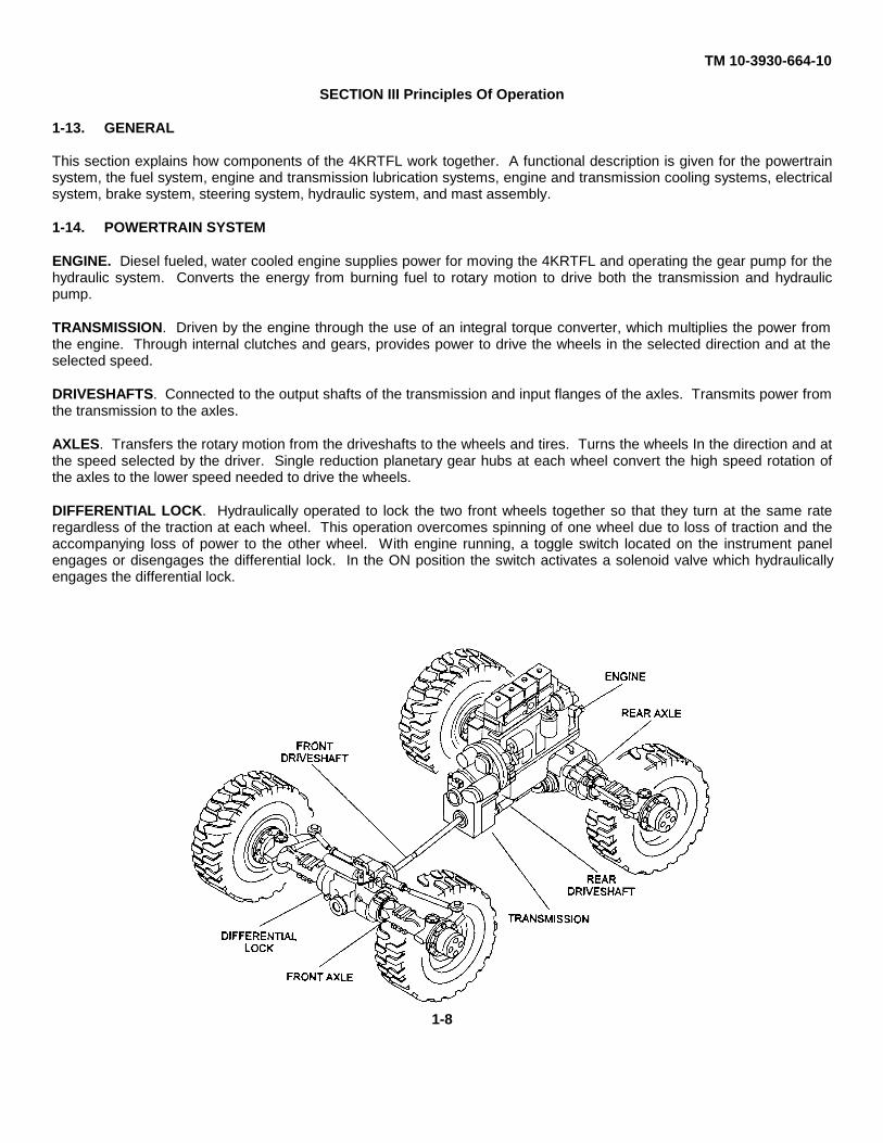
ENGINE. Diesel fueled, water cooled engine supplies power for moving the 4KRTFL and operating the gear pump for thehydraulic system. Converts the energy from burning fuel to rotary motion to drive both the transmission and hydraulicpump.
TRANSMISSION. Driven by the engine through the use of an integral torque converter, which multiplies the power fromthe engine. Through internal clutches and gears, provides power to drive the wheels in the selected direction and at theselected speed.
DRIVESHAFTS. Connected to the output shafts of the transmission and input flanges of the axles. Transmits power fromthe transmission to the axles.
AXLES. Transfers the rotary motion from the driveshafts to the wheels and tires. Turns the wheels In the direction and atthe speed selected by the driver. Single reduction planetary gear hubs at each wheel convert the high speed rotation ofthe axles to the lower speed needed to drive the wheels.
DIFFERENTIAL LOCK. Hydraulically operated to lock the two front wheels together so that they turn at the same rateregardless of the traction at each wheel. This operation overcomes spinning of one wheel due to loss of traction and theaccompanying loss of power to the other wheel. With engine running, a toggle switch located on the instrument panelengages or disengages the differential lock. In the ON position the switch activates a solenoid valve which hydraulicallyengages the differential lock.
1-8
TM 10-3930-664-10
1-15. FUEL SYSTEM
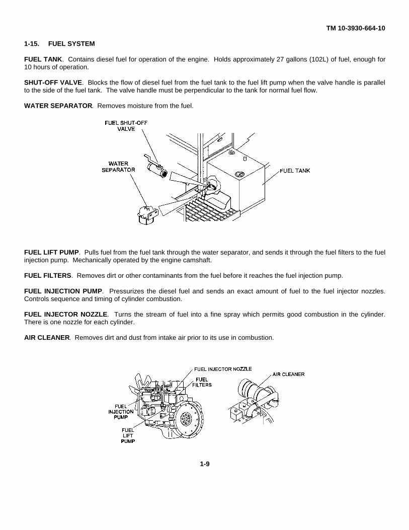
FUEL TANK. Contains diesel fuel for operation of the engine. Holds approximately 27 gallons (102L) of fuel, enough for10 hours of operation.
SHUT-OFF VALVE. Blocks the flow of diesel fuel from the fuel tank to the fuel lift pump when the valve handle is parallelto the side of the fuel tank. The valve handle must be perpendicular to the tank for normal fuel flow.
WATER SEPARATOR. Removes moisture from the fuel.
FUEL LIFT PUMP. Pulls fuel from the fuel tank through the water separator, and sends it through the fuel filters to the fuelinjection pump. Mechanically operated by the engine camshaft.
FUEL FILTERS. Removes dirt or other contaminants from the fuel before it reaches the fuel injection pump.
FUEL INJECTION PUMP. Pressurizes the diesel fuel and sends an exact amount of fuel to the fuel injector nozzles.Controls sequence and timing of cylinder combustion.
FUEL INJECTOR NOZZLE. Turns the stream of fuel into a fine spray which permits good combustion in the cylinder.There is one nozzle for each cylinder.
AIR CLEANER. Removes dirt and dust from intake air prior to its use in combustion.
1-9
TM 10-3930-664-10
1-16. ENGINE LUBRICATION AND COOLING SYSTEMS
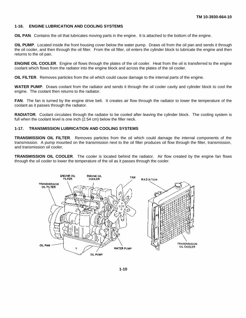
OIL PAN. Contains the oil that lubricates moving parts in the engine. It is attached to the bottom of the engine.
OIL PUMP. Located inside the front housing cover below the water pump. Draws oil from the oil pan and sends it throughthe oil cooler, and then through the oil filter. From the oil filter, oil enters the cylinder block to lubricate the engine and thenreturns to the oil pan.
ENGINE OIL COOLER. Engine oil flows through the plates of the oil cooler. Heat from the oil is transferred to the enginecoolant which flows from the radiator into the engine block and across the plates of the oil cooler.
OIL FILTER. Removes particles from the oil which could cause damage to the internal parts of the engine.
WATER PUMP. Draws coolant from the radiator and sends it through the oil cooler cavity and cylinder block to cool theengine. The coolant then returns to the radiator.
FAN. The fan is turned by the engine drive belt. It creates air flow through the radiator to lower the temperature of thecoolant as it passes through the radiator.
RADIATOR. Coolant circulates through the radiator to be cooled after leaving the cylinder block. The cooling system isfull when the coolant level is one inch (2.54 cm) below the filler neck.
1-17. TRANSMISSION LUBRICATION AND COOLING SYSTEMS
TRANSMISSION OIL FILTER. Removes particles from the oil which could damage the internal components of thetransmission. A pump mounted on the transmission next to the oil filter produces oil flow through the filter, transmission,and transmission oil cooler.
TRANSMISSION OIL COOLER. The cooler is located behind the radiator. Air flow created by the engine fan flowsthrough the oil cooler to lower the temperature of the oil as it passes through the cooler.
1-10
TM 10-3930-664-10
1-18. ELECTRICAL SYSTEM
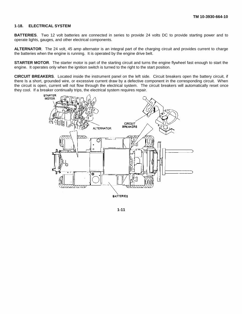
BATTERIES. Two 12 volt batteries are connected in series to provide 24 volts DC to provide starting power and tooperate lights, gauges, and other electrical components.
ALTERNATOR. The 24 volt, 45 amp alternator is an integral part of the charging circuit and provides current to chargethe batteries when the engine is running. It is operated by the engine drive belt.
STARTER MOTOR. The starter motor is part of the starting circuit and turns the engine flywheel fast enough to start theengine. It operates only when the ignition switch is turned to the right to the start position.
CIRCUIT BREAKERS. Located inside the instrument panel on the left side. Circuit breakers open the battery circuit, ifthere Is a short, grounded wire, or excessive current draw by a defective component in the corresponding circuit. Whenthe circuit is open, current will not flow through the electrical system. The circuit breakers will automatically reset oncethey cool. If a breaker continually trips, the electrical system requires repair.
1-11
TM 10-3930-664-101-19. BRAKE SYSTEM
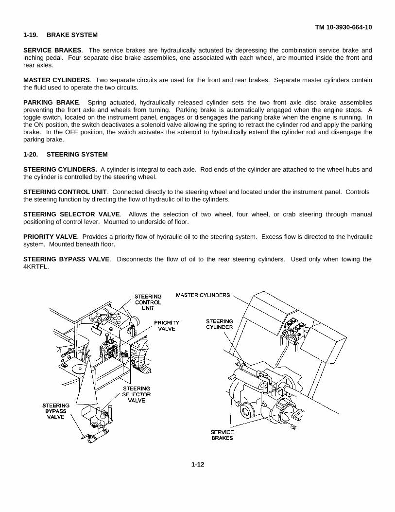
SERVICE BRAKES. The service brakes are hydraulically actuated by depressing the combination service brake andinching pedal. Four separate disc brake assemblies, one associated with each wheel, are mounted inside the front andrear axles.
MASTER CYLINDERS. Two separate circuits are used for the front and rear brakes. Separate master cylinders containthe fluid used to operate the two circuits.
PARKING BRAKE. Spring actuated, hydraulically released cylinder sets the two front axle disc brake assembliespreventing the front axle and wheels from turning. Parking brake is automatically engaged when the engine stops. Atoggle switch, located on the instrument panel, engages or disengages the parking brake when the engine is running. Inthe ON position, the switch deactivates a solenoid valve allowing the spring to retract the cylinder rod and apply the parkingbrake. In the OFF position, the switch activates the solenoid to hydraulically extend the cylinder rod and disengage theparking brake.
1-20. STEERING SYSTEM
STEERING CYLINDERS. A cylinder is integral to each axle. Rod ends of the cylinder are attached to the wheel hubs andthe cylinder is controlled by the steering wheel.
STEERING CONTROL UNIT. Connected directly to the steering wheel and located under the instrument panel. Controlsthe steering function by directing the flow of hydraulic oil to the cylinders.
STEERING SELECTOR VALVE. Allows the selection of two wheel, four wheel, or crab steering through manualpositioning of control lever. Mounted to underside of floor.
PRIORITY VALVE. Provides a priority flow of hydraulic oil to the steering system. Excess flow is directed to the hydraulicsystem. Mounted beneath floor.
STEERING BYPASS VALVE. Disconnects the flow of oil to the rear steering cylinders. Used only when towing the4KRTFL.
1-12
TM 10-3930-664-101-21. HYDRAULIC SYSTEM
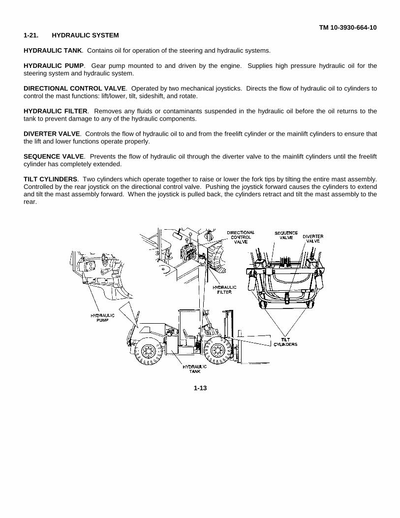
HYDRAULIC TANK. Contains oil for operation of the steering and hydraulic systems.
HYDRAULIC PUMP. Gear pump mounted to and driven by the engine. Supplies high pressure hydraulic oil for thesteering system and hydraulic system.
DIRECTIONAL CONTROL VALVE. Operated by two mechanical joysticks. Directs the flow of hydraulic oil to cylinders tocontrol the mast functions: lift/lower, tilt, sideshift, and rotate.
HYDRAULIC FILTER. Removes any fluids or contaminants suspended in the hydraulic oil before the oil returns to thetank to prevent damage to any of the hydraulic components.
DIVERTER VALVE. Controls the flow of hydraulic oil to and from the freelift cylinder or the mainlift cylinders to ensure thatthe lift and lower functions operate properly.
SEQUENCE VALVE. Prevents the flow of hydraulic oil through the diverter valve to the mainlift cylinders until the freeliftcylinder has completely extended.
TILT CYLINDERS. Two cylinders which operate together to raise or lower the fork tips by tilting the entire mast assembly.Controlled by the rear joystick on the directional control valve. Pushing the joystick forward causes the cylinders to extendand tilt the mast assembly forward. When the joystick is pulled back, the cylinders retract and tilt the mast assembly to therear.
1-13
TM 10-3930-664-10
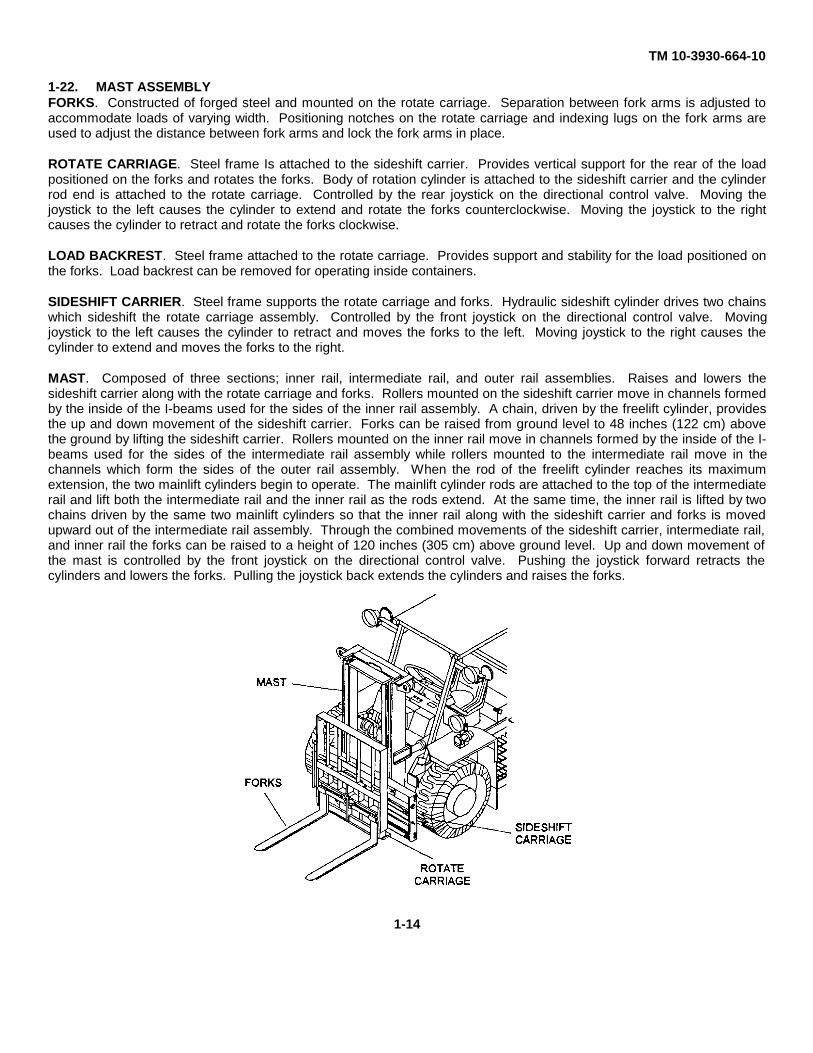
1-22. MAST ASSEMBLYFORKS. Constructed of forged steel and mounted on the rotate carriage. Separation between fork arms is adjusted toaccommodate loads of varying width. Positioning notches on the rotate carriage and indexing lugs on the fork arms areused to adjust the distance between fork arms and lock the fork arms in place.
ROTATE CARRIAGE. Steel frame Is attached to the sideshift carrier. Provides vertical support for the rear of the loadpositioned on the forks and rotates the forks. Body of rotation cylinder is attached to the sideshift carrier and the cylinderrod end is attached to the rotate carriage. Controlled by the rear joystick on the directional control valve. Moving thejoystick to the left causes the cylinder to extend and rotate the forks counterclockwise. Moving the joystick to the rightcauses the cylinder to retract and rotate the forks clockwise.
LOAD BACKREST. Steel frame attached to the rotate carriage. Provides support and stability for the load positioned onthe forks. Load backrest can be removed for operating inside containers.
SIDESHIFT CARRIER. Steel frame supports the rotate carriage and forks. Hydraulic sideshift cylinder drives two chainswhich sideshift the rotate carriage assembly. Controlled by the front joystick on the directional control valve. Movingjoystick to the left causes the cylinder to retract and moves the forks to the left. Moving joystick to the right causes thecylinder to extend and moves the forks to the right.
MAST. Composed of three sections; inner rail, intermediate rail, and outer rail assemblies. Raises and lowers thesideshift carrier along with the rotate carriage and forks. Rollers mounted on the sideshift carrier move in channels formedby the inside of the I-beams used for the sides of the inner rail assembly. A chain, driven by the freelift cylinder, providesthe up and down movement of the sideshift carrier. Forks can be raised from ground level to 48 inches (122 cm) abovethe ground by lifting the sideshift carrier. Rollers mounted on the inner rail move in channels formed by the inside of the I-beams used for the sides of the intermediate rail assembly while rollers mounted to the intermediate rail move in thechannels which form the sides of the outer rail assembly. When the rod of the freelift cylinder reaches its maximumextension, the two mainlift cylinders begin to operate. The mainlift cylinder rods are attached to the top of the intermediaterail and lift both the intermediate rail and the inner rail as the rods extend. At the same time, the inner rail is lifted by twochains driven by the same two mainlift cylinders so that the inner rail along with the sideshift carrier and forks is movedupward out of the intermediate rail assembly. Through the combined movements of the sideshift carrier, intermediate rail,and inner rail the forks can be raised to a height of 120 inches (305 cm) above ground level. Up and down movement ofthe mast is controlled by the front joystick on the directional control valve. Pushing the joystick forward retracts thecylinders and lowers the forks. Pulling the joystick back extends the cylinders and raises the forks.
1-14
TM 10-3930-664-10
CHAPTER 2
OPERATING INSTRUCTIONS
SECTION I Description And Use Of Operator’s Controls And Indicators
2-1. OPERATOR’S CONTROLS AND INDICATORS
This section locates, describes, and illustrates the controls and indicators used on the 4KRTFL.
2-2. INSTRUMENT PANEL
a. Controls
Key Control or Indicator Function
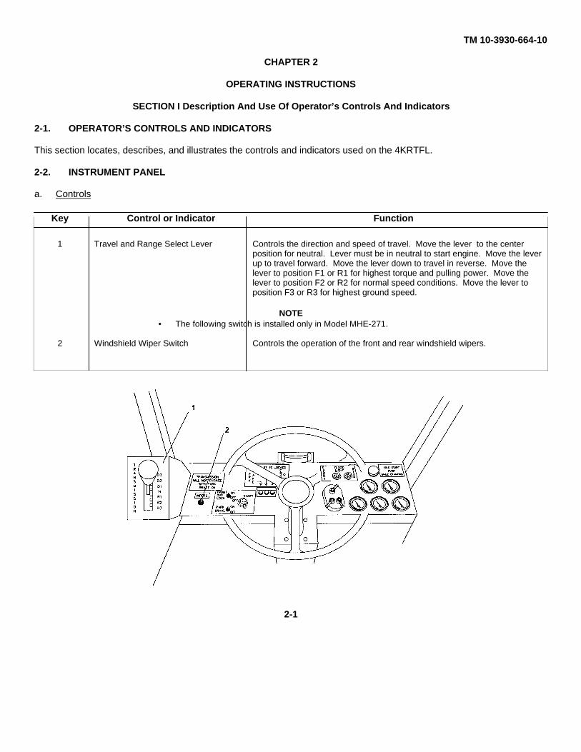
1 Travel and Range Select Lever Controls the direction and speed of travel. Move the lever to the centerposition for neutral. Lever must be in neutral to start engine. Move the leverup to travel forward. Move the lever down to travel in reverse. Move thelever to position F1 or R1 for highest torque and pulling power. Move thelever to position F2 or R2 for normal speed conditions. Move the lever toposition F3 or R3 for highest ground speed.
NOTE• The following switch is installed only in Model MHE-271.
2 Windshield Wiper Switch Controls the operation of the front and rear windshield wipers.
2-1
TM 10-3930-664-10
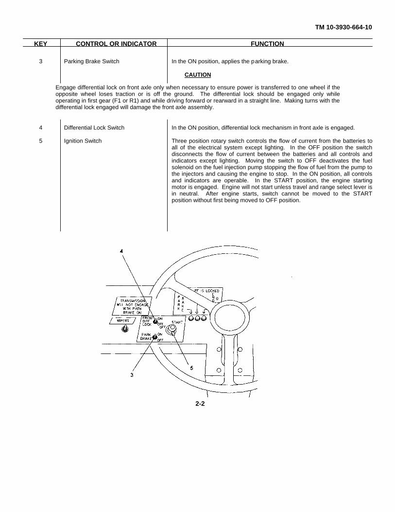
KEY CONTROL OR INDICATOR FUNCTION
3 Parking Brake Switch In the ON position, applies the parking brake.
CAUTION
4 Differential Lock Switch In the ON position, differential lock mechanism in front axle is engaged.
5 Ignition Switch Three position rotary switch controls the flow of current from the batteries toall of the electrical system except lighting. In the OFF position the switchdisconnects the flow of current between the batteries and all controls andindicators except lighting. Moving the switch to OFF deactivates the fuelsolenoid on the fuel injection pump stopping the flow of fuel from the pump tothe injectors and causing the engine to stop. In the ON position, all controlsand indicators are operable. In the START position, the engine startingmotor is engaged. Engine will not start unless travel and range select lever isin neutral. After engine starts, switch cannot be moved to the STARTposition without first being moved to OFF position.
Engage differential lock on front axle only when necessary to ensure power is transferred to one wheel if theopposite wheel loses traction or is off the ground. The differential lock should be engaged only whileoperating in first gear (F1 or R1) and while driving forward or rearward in a straight line. Making turns with thedifferential lock engaged will damage the front axle assembly.
2-2
TM 10-3930-664-10
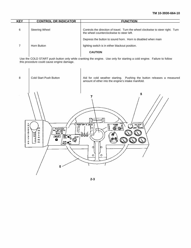
KEY CONTROL OR INDICATOR FUNCTION
6 Steering Wheel Controls the direction of travel. Turn the wheel clockwise to steer right. Turnthe wheel counterclockwise to steer left.
Depress the button to sound horn. Horn is disabled when main
7 Horn Button lighting switch is in either blackout position.
CAUTION
8 Cold Start Push Button Aid for cold weather starting. Pushing the button releases a measuredamount of ether into the engine’s intake manifold.
Use the COLD START push button only while cranking the engine. Use only for starting a cold engine. Failure to followthis procedure could cause engine damage.
2-3
TM 10-3930-664-10
b. Indicators.
KEY CONTROL OR INDICATOR FUNCTION
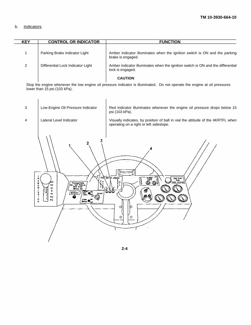
1 Parking Brake Indicator Light Amber indicator illuminates when the ignition switch is ON and the parkingbrake is engaged.
2 Differential Lock Indicator Light Amber indicator illuminates when the ignition switch is ON and the differentiallock is engaged.
CAUTION
3 Low Engine Oil Pressure Indicator Red indicator illuminates whenever the engine oil pressure drops below 15psi (103 kPa).
4 Lateral Level Indicator Visually indicates, by position of ball in vial the attitude of the 4KRTFL whenoperating on a right or left sideslope.
Stop the engine whenever the low engine oil pressure indicator is illuminated. Do not operate the engine at oil pressureslower than 15 psi (103 kPa).
2-4
TM 10-3930-664-10
c. Lighting Switches.
KEY CONTROL OR INDICATOR FUNCTION
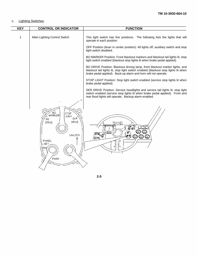
1 Main Lighting Control Switch This light switch has five positions. The following lists the lights that willoperate in each position.
OFF Position (lever in center position): All lights off, auxiliary switch and stoplight switch disabled.
BO MARKER Position: Front blackout markers and blackout tail lights lit, stoplight switch enabled (blackout stop lights lit when brake pedal applied).
BO DRIVE Position: Blackout driving lamp, front blackout marker lights, andblackout tail lights lit, stop light switch enabled (blackout stop lights lit whenbrake pedal applied). Back-up alarm and horn will not operate.
STOP LIGHT Position: Stop light switch enabled (service stop lights lit whenbrake pedal applied).
SER DRIVE Position: Service headlights and service tail lights lit, stop lightswitch enabled (service stop lights lit when brake pedal applied). Front andrear flood lights will operate. Backup alarm enabled.
2-5
TM 10-3930-664-10
KEY CONTROL OR INDICATOR FUNCTION
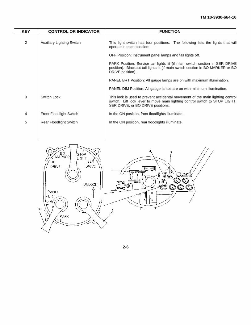
2 Auxiliary Lighting Switch This light switch has four positions. The following lists the lights that willoperate in each position:
OFF Position: Instrument panel lamps and tail lights off.
PARK Position: Service tail lights lit (if main switch section in SER DRIVEposition). Blackout tail lights lit (if main switch section in BO MARKER or BODRIVE position).
PANEL BRT Position: All gauge lamps are on with maximum illumination.
PANEL DIM Position: All gauge lamps are on with minimum illumination.
3 Switch Lock This lock is used to prevent accidental movement of the main lighting controlswitch. Lift lock lever to move main lighting control switch to STOP LIGHT,SER DRIVE, or BO DRIVE positions.
4 Front Floodlight Switch In the ON position, front floodlights illuminate.
5 Rear Floodlight Switch In the ON position, rear floodlights illuminate.
2-6
TM 10-3930-664-10
d. Gauges.
KEY OR CONTROL FUNCTION
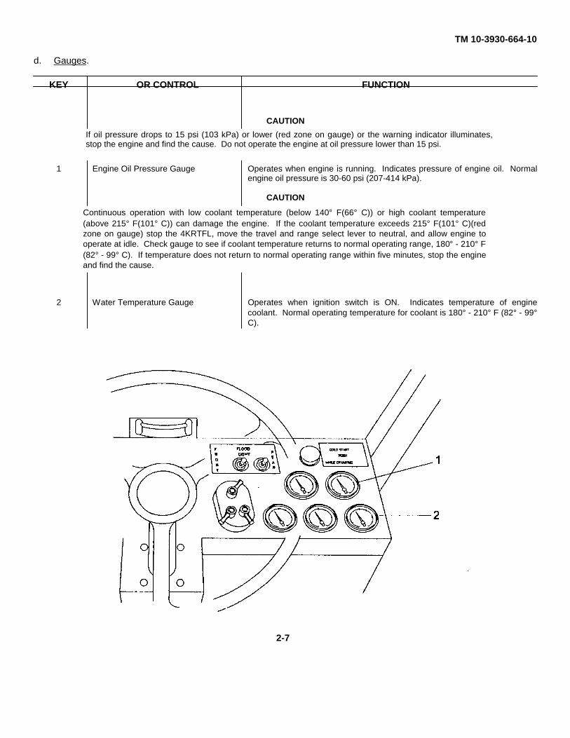
CAUTION
1 Engine Oil Pressure Gauge Operates when engine is running. Indicates pressure of engine oil. Normalengine oil pressure is 30-60 psi (207-414 kPa).
CAUTION
2 Water Temperature Gauge Operates when ignition switch is ON. Indicates temperature of enginecoolant. Normal operating temperature for coolant is 180° - 210° F (82° - 99°C).
If oil pressure drops to 15 psi (103 kPa) or lower (red zone on gauge) or the warning indicator illuminates,stop the engine and find the cause. Do not operate the engine at oil pressure lower than 15 psi.
Continuous operation with low coolant temperature (below 140° F(66° C)) or high coolant temperature(above 215° F(101° C)) can damage the engine. If the coolant temperature exceeds 215° F(101° C)(redzone on gauge) stop the 4KRTFL, move the travel and range select lever to neutral, and allow engine tooperate at idle. Check gauge to see if coolant temperature returns to normal operating range, 180° - 210° F(82° - 99° C). If temperature does not return to normal operating range within five minutes, stop the engineand find the cause.
2-7
TM 10-3930-664-10
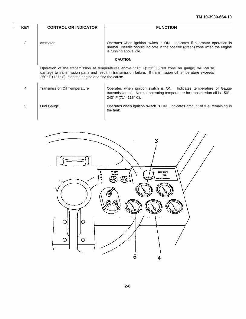
KEY CONTROL OR INDICATOR FUNCTION
3 Ammeter Operates when ignition switch is ON. Indicates if alternator operation isnormal. Needle should indicate in the positive (green) zone when the engineis running above idle.
CAUTION
4 Transmission Oil Temperature Operates when ignition switch is ON. Indicates temperature of Gaugetransmission oil. Normal operating temperature for transmission oil is 150° -240° F (71° -115° C).
5 Fuel Gauge Operates when ignition switch is ON. Indicates amount of fuel remaining inthe tank.
Operation of the transmission at temperatures above 250° F(121° C)(red zone on gauge) will causedamage to transmission parts and result in transmission failure. If transmission oil temperature exceeds250° F (121° C), stop the engine and find the cause.
2-8
TM 10-3930-664-10
2-3. OPERATOR’S STATION
a. Drivetrain Controls.
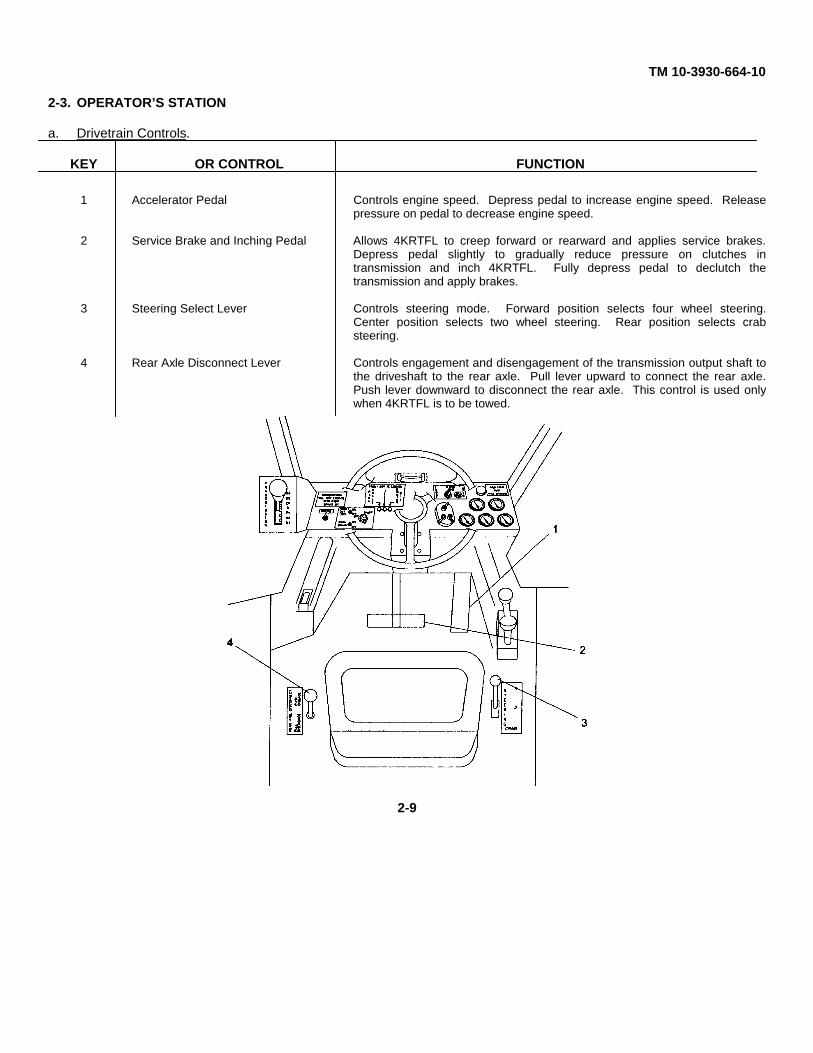
KEY OR CONTROL FUNCTION
1 Accelerator Pedal Controls engine speed. Depress pedal to increase engine speed. Releasepressure on pedal to decrease engine speed.
2 Service Brake and Inching Pedal Allows 4KRTFL to creep forward or rearward and applies service brakes.Depress pedal slightly to gradually reduce pressure on clutches intransmission and inch 4KRTFL. Fully depress pedal to declutch thetransmission and apply brakes.
3 Steering Select Lever Controls steering mode. Forward position selects four wheel steering.Center position selects two wheel steering. Rear position selects crabsteering.
4 Rear Axle Disconnect Lever Controls engagement and disengagement of the transmission output shaft tothe driveshaft to the rear axle. Pull lever upward to connect the rear axle.Push lever downward to disconnect the rear axle. This control is used onlywhen 4KRTFL is to be towed.
2-9
TM 10-3930-664-10
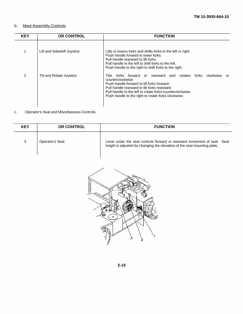
b. Mast Assembly Controls.
KEY OR CONTROL FUNCTION
1 Lift and Sideshift Joystick Lifts or lowers forks and shifts forks to the left or right.Push handle forward to lower forks.Pull handle rearward to lift forks.Pull handle to the left to shift forks to the left.Push handle to the right to shift forks to the right.
2 Tilt and Rotate Joystick Tilts forks forward or rearward and rotates forks clockwise orcounterclockwise.Push handle forward to tilt forks forward.Pull handle rearward to tilt forks rearward.Pull handle to the left to rotate forks counterclockwise.Push handle to the right to rotate forks clockwise.
c. Operator’s Seat and Miscellaneous Controls.
KEY OR CONTROL FUNCTION
3 Operator’s Seat Lever under the seat controls forward or rearward movement of seat. Seatheight is adjusted by changing the elevation of the seat mounting plate.
2-10
TM 10-3930-664-10
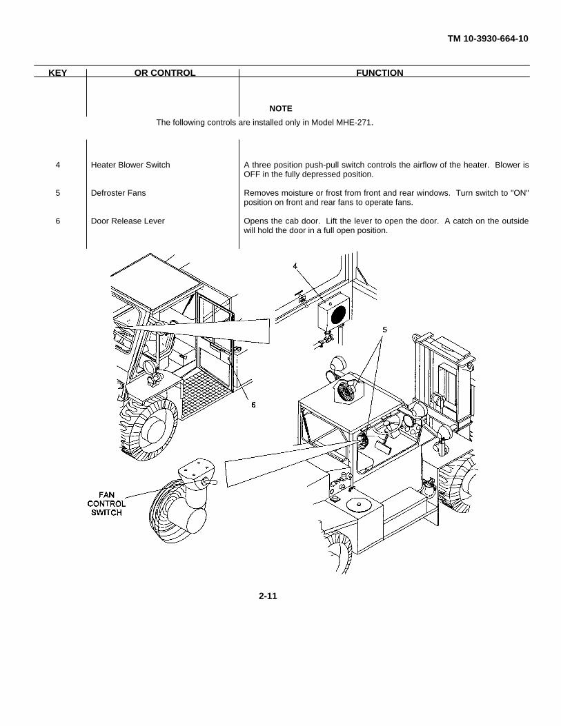
KEY OR CONTROL FUNCTION
NOTE
4 Heater Blower Switch A three position push-pull switch controls the airflow of the heater. Blower isOFF in the fully depressed position.
5 Defroster Fans Removes moisture or frost from front and rear windows. Turn switch to "ON"position on front and rear fans to operate fans.
6 Door Release Lever Opens the cab door. Lift the lever to open the door. A catch on the outsidewill hold the door in a full open position.
The following controls are installed only in Model MHE-271.
2-11
TM 10-3930-664-10
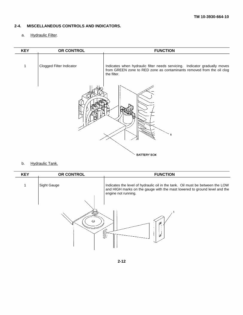
2-4. MISCELLANEOUS CONTROLS AND INDICATORS.
a. Hydraulic Filter.
KEY OR CONTROL FUNCTION
1 Clogged Filter Indicator Indicates when hydraulic filter needs servicing. Indicator gradually movesfrom GREEN zone to RED zone as contaminants removed from the oil clogthe filter.
b. Hydraulic Tank.
KEY OR CONTROL FUNCTION
1 Sight Gauge Indicates the level of hydraulic oil in the tank. Oil must be between the LOWand HIGH marks on the gauge with the mast lowered to ground level and theengine not running.
2-12
TM 10-3930-664-10
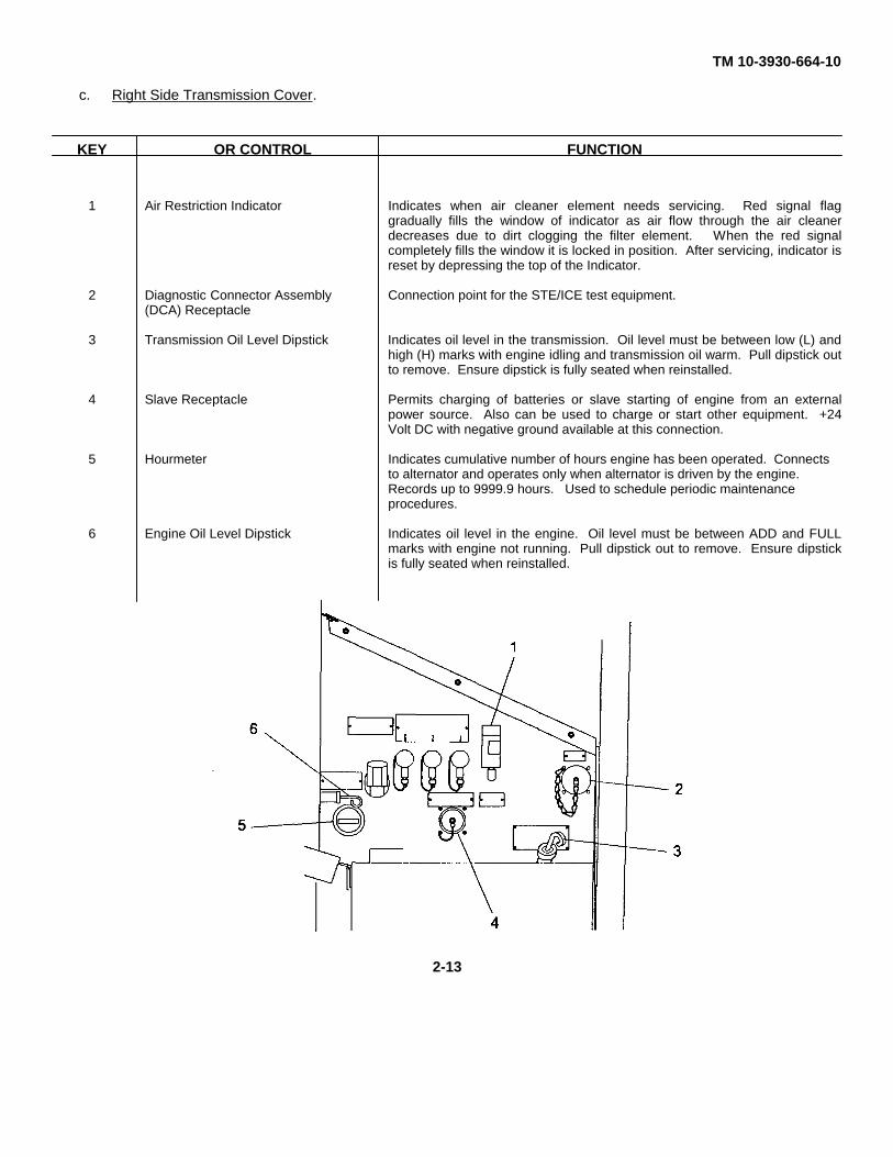
c. Right Side Transmission Cover.
KEY OR CONTROL FUNCTION
1 Air Restriction Indicator Indicates when air cleaner element needs servicing. Red signal flaggradually fills the window of indicator as air flow through the air cleanerdecreases due to dirt clogging the filter element. When the red signalcompletely fills the window it is locked in position. After servicing, indicator isreset by depressing the top of the Indicator.
2 Diagnostic Connector Assembly Connection point for the STE/ICE test equipment.(DCA) Receptacle
3 Transmission Oil Level Dipstick Indicates oil level in the transmission. Oil level must be between low (L) andhigh (H) marks with engine idling and transmission oil warm. Pull dipstick outto remove. Ensure dipstick is fully seated when reinstalled.
4 Slave Receptacle Permits charging of batteries or slave starting of engine from an externalpower source. Also can be used to charge or start other equipment. +24Volt DC with negative ground available at this connection.
5 Hourmeter Indicates cumulative number of hours engine has been operated. Connectsto alternator and operates only when alternator is driven by the engine.Records up to 9999.9 hours. Used to schedule periodic maintenanceprocedures.
6 Engine Oil Level Dipstick Indicates oil level in the engine. Oil level must be between ADD and FULLmarks with engine not running. Pull dipstick out to remove. Ensure dipstickis fully seated when reinstalled.
2-13
TM 10-3930-664-10
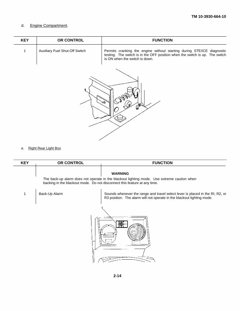
d. Engine Compartment.
KEY OR CONTROL FUNCTION
1 Auxiliary Fuel Shut-Off Switch Permits cranking the engine without starting during STE/ICE diagnostictesting. The switch is in the OFF position when the switch is up. The switchis ON when the switch is down.
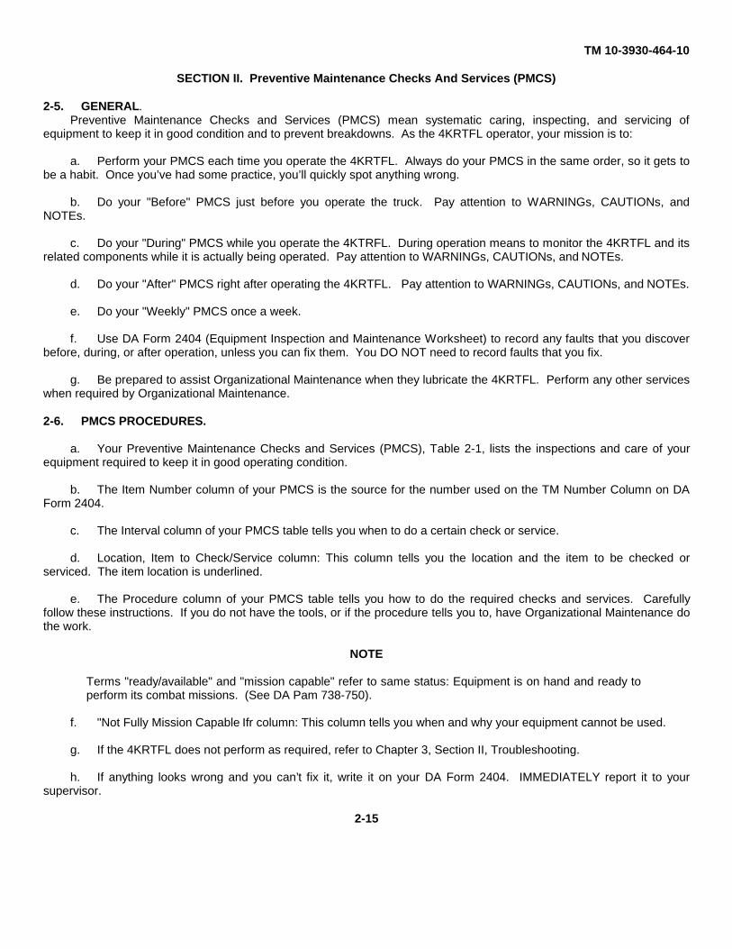
e. Right Rear Light Box
KEY OR CONTROL FUNCTION
WARNING
1 Back-Up Alarm Sounds whenever the range and travel select lever is placed in the RI, R2, orR3 position. The alarm will not operate in the blackout lighting mode.
The back-up alarm does not operate in the blackout lighting mode. Use extreme caution whenbacking in the blackout mode. Do not disconnect this feature at any time.
2-14
TM 10-3930-464-10
SECTION II. Preventive Maintenance Checks And Services (PMCS)
2-5. GENERAL.Preventive Maintenance Checks and Services (PMCS) mean systematic caring, inspecting, and servicing of
equipment to keep it in good condition and to prevent breakdowns. As the 4KRTFL operator, your mission is to:
a. Perform your PMCS each time you operate the 4KRTFL. Always do your PMCS in the same order, so it gets tobe a habit. Once you’ve had some practice, you’ll quickly spot anything wrong.
b. Do your "Before" PMCS just before you operate the truck. Pay attention to WARNINGs, CAUTIONs, andNOTEs.
c. Do your "During" PMCS while you operate the 4KTRFL. During operation means to monitor the 4KRTFL and itsrelated components while it is actually being operated. Pay attention to WARNINGs, CAUTIONs, and NOTEs.
d. Do your "After" PMCS right after operating the 4KRTFL. Pay attention to WARNINGs, CAUTIONs, and NOTEs.
e. Do your "Weekly" PMCS once a week.
f. Use DA Form 2404 (Equipment Inspection and Maintenance Worksheet) to record any faults that you discoverbefore, during, or after operation, unless you can fix them. You DO NOT need to record faults that you fix.
g. Be prepared to assist Organizational Maintenance when they lubricate the 4KRTFL. Perform any other serviceswhen required by Organizational Maintenance.
2-6. PMCS PROCEDURES.
a. Your Preventive Maintenance Checks and Services (PMCS), Table 2-1, lists the inspections and care of yourequipment required to keep it in good operating condition.
b. The Item Number column of your PMCS is the source for the number used on the TM Number Column on DAForm 2404.
c. The Interval column of your PMCS table tells you when to do a certain check or service.
d. Location, Item to Check/Service column: This column tells you the location and the item to be checked orserviced. The item location is underlined.
e. The Procedure column of your PMCS table tells you how to do the required checks and services. Carefullyfollow these instructions. If you do not have the tools, or if the procedure tells you to, have Organizational Maintenance dothe work.
NOTE
Terms "ready/available" and "mission capable" refer to same status: Equipment is on hand and ready toperform its combat missions. (See DA Pam 738-750).
f. "Not Fully Mission Capable Ifr column: This column tells you when and why your equipment cannot be used.
g. If the 4KRTFL does not perform as required, refer to Chapter 3, Section II, Troubleshooting.
h. If anything looks wrong and you can’t fix it, write it on your DA Form 2404. IMMEDIATELY report it to yoursupervisor.
2-15
TM 10-3930-664-10
I. When you do your PMCS, you will always need a rag or two. Following are checks that are common to theentire 4KRTFL:
WARNING
• Dry cleaning solvent P-D-680 is toxic and flammable. Wear protective goggles and gloves and use onlyin well ventilated area. Avoid contact with skin, eyes and clothes and don’t breathe vapors. Do not usenear open flame or excessive heat. The flash point is 1000 F - 138° F (38° C - 50° C). If you becomedizzy while using cleaning solvent, get fresh air immediately and get medical aid. If contact with eyes ismade, wash your eyes with water and get medical aid immediately. Cleaning solvents evaporate quicklyand can irritate exposed skin if solvents contact skin. In cold weather, contact of exposed skin withcleaning solvents can cause frostbite.
• DO NOT use diesel fuel, gasoline, or benzene (benzol) for cleaning.
CAUTION
• Keep cleaning solvents, gasoline, and lubricants away from rubber or soft plastic parts. They willdeteriorate material.
• When cleaning the 4KRTFL with high pressure water, do not use direct pressure washing for thebackup alarm. Immersing the backup alarm in high pressure water can cause the alarm to fail.
(1) Keep It Clean. Dirt, grease, oil, and debris only get in the way and may cover up a serious problem. Cleanas you work and as needed. Use dry cleaning solvent (P-D-680) on all metal surfaces. Use soap and water when youclean rubber or plastic material. Upholstery can be cleaned with soap and water and a clean, damp cloth.
(2) Rust and Corrosion. Check 4RTFL body and mast for rust and corrosion. If any bare metal or corrosionexists, clean, and apply a thin coat of oil. Report it to your supervisor.
(3) Bolts, Nuts, and Screws. Check them all for obvious looseness, missing, bent, or broken condition. Lookfor chipped paint, bare metal, or rust around bolt heads. If you find a loose bolt, nut, or screw, report it to your supervisor.
(4) Welds. Look for loose or chipped paint, rust, or gaps where parts are welded together. If you find a badweld, report it to your supervisor.
(5) Electric Wires and Connectors. Look for cracked, frayed, or broken insulation, bare wires, and loose orbroken connectors. Report any damaged wires to your supervisor.
(6) Hoses and Fluid Lines. Look for wear, damage, leaks, and make sure clamps and fittings are tight. Wetspots show leaks, but a stain around a fitting or connector can also mean a leak. If a leak comes from a loose fitting orconnector, or if something is broken or worn out, report it to your supervisor.
j. When you check for "operating condition," you look at the component to see if it’s serviceable.
2-7. LEAKAGE DEFINITIONS FOR OPERATOR PMCS
It is necessary for you to know how fluid leakage affects the status of the 4KRTFL. Following are types/classes of leakagean operator needs to know to be able to determine the status of the 4KRTFL. Learn these leakage definitions andremember - when in doubt, notify your supervisor.
2-16
TM 10-3930-664-10
CAUTION
• Equipment operation is allowable with minor leakages (Class I or II). Of course, considerationmust be given to fluid capacity in the item/system being checked/inspected. When in doubt,notify your supervisor.
• When operating with Class I or II leaks, continue to check fluid levels as required in yourPMCS.
• Class III leaks should be reported immediately to your supervisor.
a. CLASS I - Seepage of fluid (as indicated by wetness or discoloration) not great enough to form drops.
b. CLASS II - Leakage of fluid great enough to form drops but not enough to cause drops to drip from item beingchecked/inspected.
c. CLASS III - Leakage of fluid great enough to form drops that fall from item being checked/inspected.
Table 2-1. PREVENTIVE MAINTENANCE CHECKS AND SERVICES FORMODELS MHE-270 AND MHE-271
LocationItem Interval Item to Procedure Not Fully MissionNo. Check/ Capable If:
Service
IMPORTANT
Perform "Weekly" as well as "Before" operators PMCS if:
1. You are the assigned operator and have not operatedthe vehicle since the last weekly check.
2. You are operating the vehicle for the f irst time.
WARNING
Unless otherwise specified, perform all maintenanceprocedures with all equipment lowered to the ground,transmission in neutral, parking brake applied, and theengine stopped. Failure to perform these tasks couldcause personal injury or death.
2-17
TM 10-3930-664-10
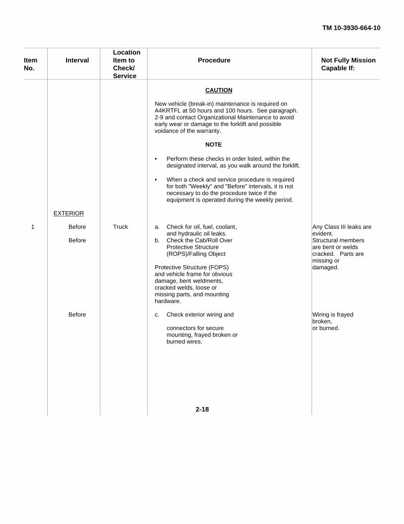
LocationItem Interval Item to Procedure Not Fully MissionNo. Check/ Capable If:
Service
CAUTION
New vehicle (break-in) maintenance is required onA4KRTFL at 50 hours and 100 hours. See paragraph.2-9 and contact Organizational Maintenance to avoidearly wear or damage to the forklift and possiblevoidance of the warranty.
NOTE
• Perform these checks in order listed, within thedesignated interval, as you walk around the forklift.
• When a check and service procedure is requiredfor both "Weekly" and "Before" intervals, it is notnecessary to do the procedure twice if theequipment is operated during the weekly period.
EXTERIOR
1 Before Truck a. Check for oil, fuel, coolant, Any Class III leaks are and hydraulic oil leaks. evident.
Before b. Check the Cab/Roll Over Structural membersProtective Structure are bent or welds(ROPS)/Falling Object cracked. Parts are
missing orProtective Structure (FOPS) damaged.and vehicle frame for obviousdamage, bent weldments,cracked welds, loose ormissing parts, and mountinghardware.
Before c. Check exterior wiring and Wiring is frayedbroken,
connectors for secure or burned.mounting, frayed broken orburned wires.
2-18
TM 10-3930-664-10
LocationItem Interval Item to Procedure Not Fully MissionNo. Check/ Capable If:
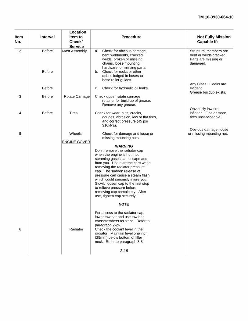
Service2 Before Mast Assembly a. Check for obvious damage, Structural members are
bent weldments, cracked bent or welds cracked.welds, broken or missing Parts are missing orchains, loose mounting damaged.hardware, or missing parts.
Before b. Check for rocks or otherdebris lodged in hoses orhose roller guides.
Any Class III leaks areBefore c. Check for hydraulic oil leaks. evident.
Grease buildup exists.3 Before Rotate Carriage Check upper rotate carriage
retainer for build up of grease.Remove any grease.
Obviously low tire4 Before Tires Check for wear, cuts, cracks, inflation. One or more
gouges, abrasion, low or flat tires, tires unserviceable.and correct pressure (45 psi310kPa).
Obvious damage, loose5 Wheels Check for damage and loose or or missing mounting nut.
missing mounting nuts.ENGINE COVER
WARNINGDon’t remove the radiator capwhen the engine is hot; hotsteaming gases can escape andbum you. Use extreme care whenremoving the radiator pressurecap. The sudden release ofpressure can cause a steam flashwhich could seriously injure you.Slowly loosen cap to the first stopto relieve pressure beforeremoving cap completely. Afteruse, tighten cap securely.
NOTE
For access to the radiator cap,lower tow bar and use tow barcrossmembers as steps. Refer toparagraph 2-26.
6 Radiator Check the coolant level in theradiator. Maintain level one inch(25mm) below bottom of fillerneck. Refer to paragraph 3-8.
2-19
TM 10-3930-664-10
LocationItem Interval Item to Procedure Not Fully MissionNo. Check/ Capable If:
Service
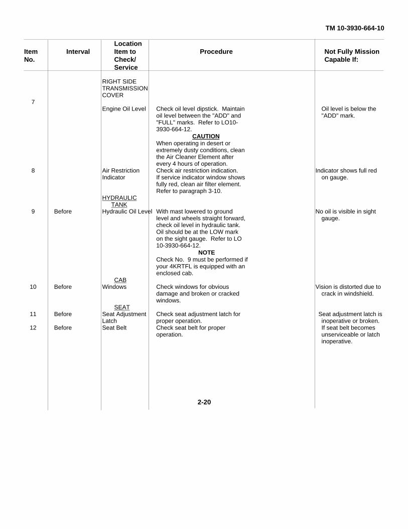
RIGHT SIDETRANSMISSIONCOVER
7Engine Oil Level Check oil level dipstick. Maintain Oil level is below the
oil level between the "ADD" and "ADD" mark."FULL" marks. Refer to LO10-3930-664-12.
CAUTIONWhen operating in desert orextremely dusty conditions, cleanthe Air Cleaner Element afterevery 4 hours of operation.
8 Air Restriction Check air restriction indication. Indicator shows full redIndicator If service indicator window shows on gauge.
fully red, clean air filter element.Refer to paragraph 3-10.
HYDRAULICTANK
9 Before Hydraulic Oil Level With mast lowered to ground No oil is visible in sightlevel and wheels straight forward, gauge.check oil level in hydraulic tank.Oil should be at the LOW markon the sight gauge. Refer to LO10-3930-664-12.
NOTECheck No. 9 must be performed ifyour 4KRTFL is equipped with anenclosed cab.
CAB10 Before Windows Check windows for obvious Vision is distorted due to
damage and broken or cracked crack in windshield.windows.
SEAT11 Before Seat Adjustment Check seat adjustment latch for Seat adjustment latch is
Latch proper operation. inoperative or broken.12 Before Seat Belt Check seat belt for proper If seat belt becomes
operation. unserviceable or latchinoperative.
2-20
TM 10-3930-664-10
LocationItem Interval Item to Procedure Not Fully MissionNo. Check/ Capable If:
Service
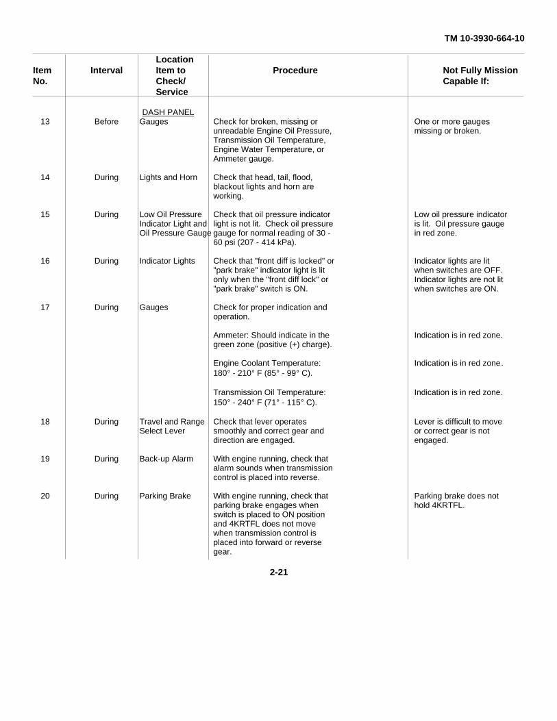
DASH PANEL13 Before Gauges Check for broken, missing or One or more gauges
unreadable Engine Oil Pressure, missing or broken.Transmission Oil Temperature,Engine Water Temperature, orAmmeter gauge.
14 During Lights and Horn Check that head, tail, flood,blackout lights and horn areworking.
15 During Low Oil Pressure Check that oil pressure indicator Low oil pressure indicatorIndicator Light and light is not lit. Check oil pressure is lit. Oil pressure gaugeOil Pressure Gauge gauge for normal reading of 30 - in red zone.
60 psi (207 - 414 kPa).
16 During Indicator Lights Check that "front diff is locked" or Indicator lights are lit"park brake" indicator light is lit when switches are OFF.only when the "front diff lock" or Indicator lights are not lit"park brake" switch is ON. when switches are ON.
17 During Gauges Check for proper indication andoperation.
Ammeter: Should indicate in the Indication is in red zone.green zone (positive (+) charge).
Engine Coolant Temperature: Indication is in red zone.180° - 210° F (85° - 99° C).
Transmission Oil Temperature: Indication is in red zone.150° - 240° F (71° - 115° C).
18 During Travel and Range Check that lever operates Lever is difficult to moveSelect Lever smoothly and correct gear and or correct gear is not
direction are engaged. engaged.
19 During Back-up Alarm With engine running, check thatalarm sounds when transmissioncontrol is placed into reverse.
20 During Parking Brake With engine running, check that Parking brake does notparking brake engages when hold 4KRTFL.switch is placed to ON positionand 4KRTFL does not movewhen transmission control isplaced into forward or reversegear.
2-21
TM 10-3930-664-10Location
Item Interval Item to Procedure Not Fully MissionNo. Check/ Capable If:
ServiceOPERATOR’S
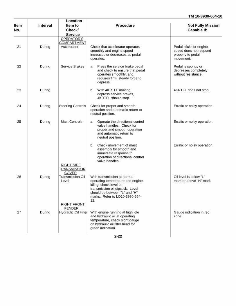
COMPARTMENT21 During Accelerator Check that accelerator operates Pedal sticks or engine
smoothly and engine speed speed does not respondincreases or decreases as pedal properly to pedaloperates. movement.
22 During Service Brakes a. Press the service brake pedal Pedal is spongy orand check to ensure that pedal depresses completelyoperates smoothly, and without resistance.requires firm, steady force todepress.
23 During b. With 4KRTFL moving, 4KRTFL does not stop.depress service brakes,4KRTFL should stop.
24 During Steering Controls Check for proper and smooth Erratic or noisy operation.operation and automatic return toneutral position.
25 During Mast Controls a. Operate the directional control Erratic or noisy operation.valve handles. Check forproper and smooth operationand automatic return toneutral position.
b. Check movement of mast Erratic or noisy operation.assembly for smooth andimmediate response tooperation of directional controlvalve handles.
RIGHT SIDETRANSMISSION
COVER26 During Transmission Oil With transmission at normal Oil level is below "L"
Level operating temperature and engine mark or above "H" mark.idling, check level ontransmission oil dipstick. Levelshould be between "L" and "H"marks. Refer to LO10-3930-664-12.
RIGHT FRONTFENDER
27 During Hydraulic Oil Filter With engine running at high idle Gauge indication in redand hydraulic oil at operating zone.temperature, check sight gaugeon hydraulic oil filter head forgreen indication.
2-22
TM 10-3930-664-10Location
Item Interval Item to Procedure Not Fully MissionNo. Check/ Capable If:
Service
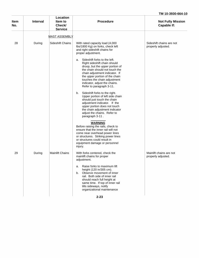
MAST ASSEMBLY
28 During Sideshift Chains With rated capacity load (4,000 Sideshift chains are notlbs/1800 Kg) on forks, check left properly adjusted.and right sideshift chains forproper adjustment.
a. Sideshift forks to the left.Right sideshift chain shoulddroop, but the upper portion ofthe chain should not touch thechain adjustment indicator. Ifthe upper portion of the chaintouches the chain adjustmentindicator, adjust the chains.Refer to paragraph 3-11.
b. Sideshift forks to the right.Upper portion of left side chainshould just touch the chainadjustment indicator. If theupper portion does not touchthe chain adjustment indicatoradjust the chains. Refer toparagraph 3-11 .
WARNINGBefore raising the rails, check toensure that the inner rail will notcome near overhead power linesor structures. Striking power linesor structures could result inequipment damage or personnelinjury.
29 During Mainlift Chains With forks centered, check the Mainlift chains are notmainlift chains for proper properly adjusted.adjustment.
a. Raise forks to maximum liftheight (120 in/305 cm).
b. Observe movement of innerrail. Both side of inner railshould reach full height atsame time. If top of inner railtilts sideways, notifyorganizational maintenance
2-23
TM 10-3930-664-10Location
Item Interval Item to Procedure Not Fully MissionNo. Check/ Capable If:
Service
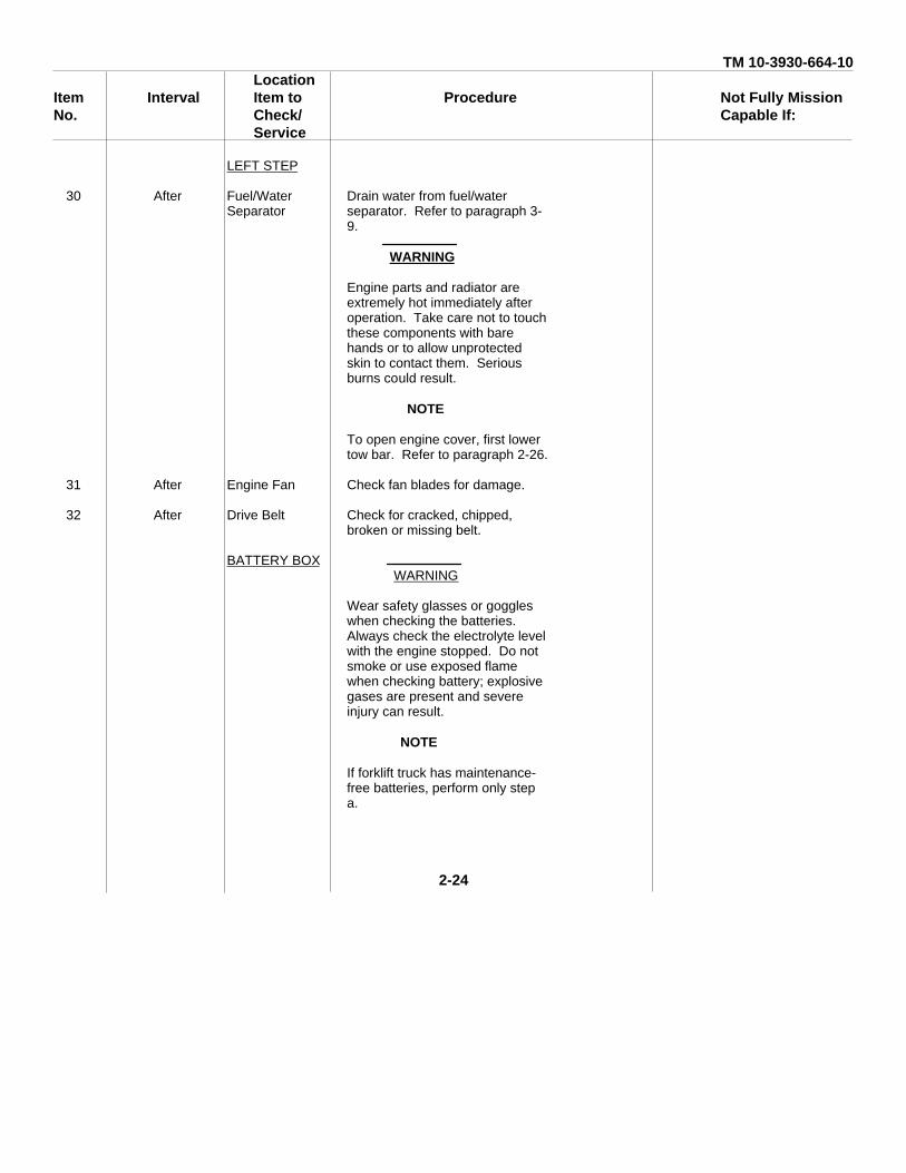
LEFT STEP
30 After Fuel/Water Drain water from fuel/waterSeparator separator. Refer to paragraph 3-
9.
WARNING
Engine parts and radiator areextremely hot immediately afteroperation. Take care not to touchthese components with barehands or to allow unprotectedskin to contact them. Seriousburns could result.
NOTE
To open engine cover, first lowertow bar. Refer to paragraph 2-26.
31 After Engine Fan Check fan blades for damage.
32 After Drive Belt Check for cracked, chipped,broken or missing belt.
BATTERY BOXWARNING
Wear safety glasses or goggleswhen checking the batteries.Always check the electrolyte levelwith the engine stopped. Do notsmoke or use exposed flamewhen checking battery; explosivegases are present and severeinjury can result.
NOTE
If forklift truck has maintenance-free batteries, perform only stepa.
2-24
TM 10-3930-664-10Location
Item Interval Item to Procedure Not Fully MissionNo. Check/ Capable If:
Service
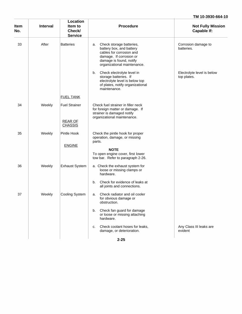
33 After Batteries a. Check storage batteries, Corrosion damage tobattery box, and battery batteries.cables for corrosion anddamage. If corrosion ordamage is found, notifyorganizational maintenance.
b. Check electrolyte level in Electrolyte level is belowstorage batteries. If top plates.electrolyte level is below topof plates, notify organizationalmaintenance.
FUEL TANK
34 Weekly Fuel Strainer Check fuel strainer in filler neckfor foreign matter or damage. Ifstrainer is damaged notifyorganizational maintenance.
REAR OFCHASSIS
35 Weekly Pintle Hook Check the pintle hook for properoperation, damage, or missingparts.
ENGINENOTE
To open engine cover, first lowertow bar. Refer to paragraph 2-26.
36 Weekly Exhaust System a. Check the exhaust system forloose or missing clamps orhardware.
b. Check for evidence of leaks atall joints and connections.
37 Weekly Cooling System a. Check radiator and oil coolerfor obvious damage orobstruction.
b. Check fan guard for damageor loose or missing attachinghardware.
c. Check coolant hoses for leaks, Any Class III leaks aredamage, or deterioration. evident
2-25
TM 10-3930-664-10Location
Item Interval Item to Procedure Not Fully MissionNo. Check/ Capable If:
Service
38 Weekly Engine Lubrication Check for oil leaks at the valve Any Class III leaks areSystem covers, push rod cover and evident.
engine oil filter.
CABNOTE
The following additional checksmust be performed if your4KRTFL is equipped with anenclosed cab.
39 Weekly Windshield Wipers a. Check the windshield wipers Wiper blades missing orblades for cracks, tears, or damage.deterioration.
b. Check the windshield wipers Wipers inoperative.for proper operation. Check toensure that sweep of blades issmooth and glass is cleared ofwater without streaks ormisses.
40 Weekly Heater Check the heater for properoperation.
41 Weekly Defroster Fans Check the defroster fans forproper operation.
SECTION III. Operation Under Usual Conditions
2-8. GENERAL
It is essential that the operator know how to perform every operation of which the vehicle is capable. This section givesinstructions on starting and stopping the vehicle, on the basic motions of the vehicle, and how to use these instructions toperform specific tasks for which the equipment was designed.
2-9. NEW VEHICLE BREAK-IN.
Controlled break-in is the ideal fitting of all internal moving metal parts. Using the proper oil and preventive maintenanceprogram during this period will provide long life of the engine.
a. Starting the Engine. See paragraph 2-10. Warm the engine to operating temperature, 180° - 210° F (82° - 99°C), before placing the engine under load.
b. Operation.
(1) Avoid constant speeds.
2-26
TM 10-3930-664-10
(2) To prevent engine lugging use the travel and range select lever to place the transmission in the appropriategear.
(3) Check the gauges to ensure normal operation of the engine.
(4) Check the coolant level and fill as necessary (refer to paragraph 3-8).
(5) Check the oil level. Add oil as necessary to keep it at the correct level (refer to LO 10-3930-664-12). Donot overfill the crankcase.
(6) After the first 50 hours of operation, the transmission oil filter and hydraulic oil filter must be changed.Contact Organizational Maintenance to change the filters. After the first 100 hours of operation, all the items listed belowmust be changed. Contact Organizational Maintenance to change the items listed below and lubricate the vehicle withcorrect grade of lubricant according to L010-3930-664-12.
Transmission Oil FilterHydraulic Oil FilterEngine Oil and FilterFuel FiltersPlanetary Gear OilDifferential Oil
2-10. STARTING THE ENGINE.
WARNING
Before operating the 4KRTFL ensure your seat belt is fastened.
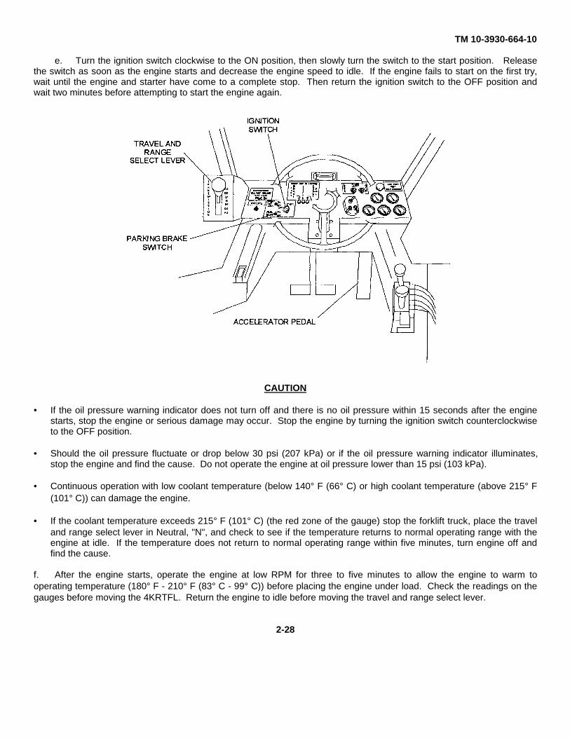
a. Adjust the operators seat so that when your seat belt is buckled you can still depress the service brake andinching and accelerator pedals.
NOTE
Before starting the 4KRTFL, ensure that the parking brake is engaged.
b. Engage the parking brake by placing the PARK BRAKE switch to ON.
NOTE
Before starting the 4KRTFL, ensure that the travel and range select lever is in the neutral position.
c. If the travel and range select lever is not in the neutral position, move the lever to neutral, "N".
d. Depress the accelerator pedal to approximately half of its travel.
CAUTION
Do not operate the starting motor for more than 30 seconds. If engine does not start within 30seconds, wait two minutes before trying to start the engine again. Continuous cranking canoverheat and damage the starting motor.
2-27
TM 10-3930-664-10
e. Turn the ignition switch clockwise to the ON position, then slowly turn the switch to the start position. Releasethe switch as soon as the engine starts and decrease the engine speed to idle. If the engine fails to start on the first try,wait until the engine and starter have come to a complete stop. Then return the ignition switch to the OFF position andwait two minutes before attempting to start the engine again.
CAUTION
• If the oil pressure warning indicator does not turn off and there is no oil pressure within 15 seconds after the enginestarts, stop the engine or serious damage may occur. Stop the engine by turning the ignition switch counterclockwiseto the OFF position.
• Should the oil pressure fluctuate or drop below 30 psi (207 kPa) or if the oil pressure warning indicator illuminates,stop the engine and find the cause. Do not operate the engine at oil pressure lower than 15 psi (103 kPa).
• Continuous operation with low coolant temperature (below 140° F (66° C) or high coolant temperature (above 215° F(101° C)) can damage the engine.
• If the coolant temperature exceeds 215° F (101° C) (the red zone of the gauge) stop the forklift truck, place the traveland range select lever in Neutral, "N", and check to see if the temperature returns to normal operating range with theengine at idle. If the temperature does not return to normal operating range within five minutes, turn engine off andfind the cause.
f. After the engine starts, operate the engine at low RPM for three to five minutes to allow the engine to warm tooperating temperature (180° F - 210° F (83° C - 99° C)) before placing the engine under load. Check the readings on thegauges before moving the 4KRTFL. Return the engine to idle before moving the travel and range select lever.
2-28
TM 10-3930-664-10
2-11. MOVING THE FORKLIFT
WARNING
Use care when backing up. Have someone direct you if you cannot see where you are going. Watchclearances.
a. Operating Safely.
(1) Do not allow riders on the 4KRTFL.
WARNING
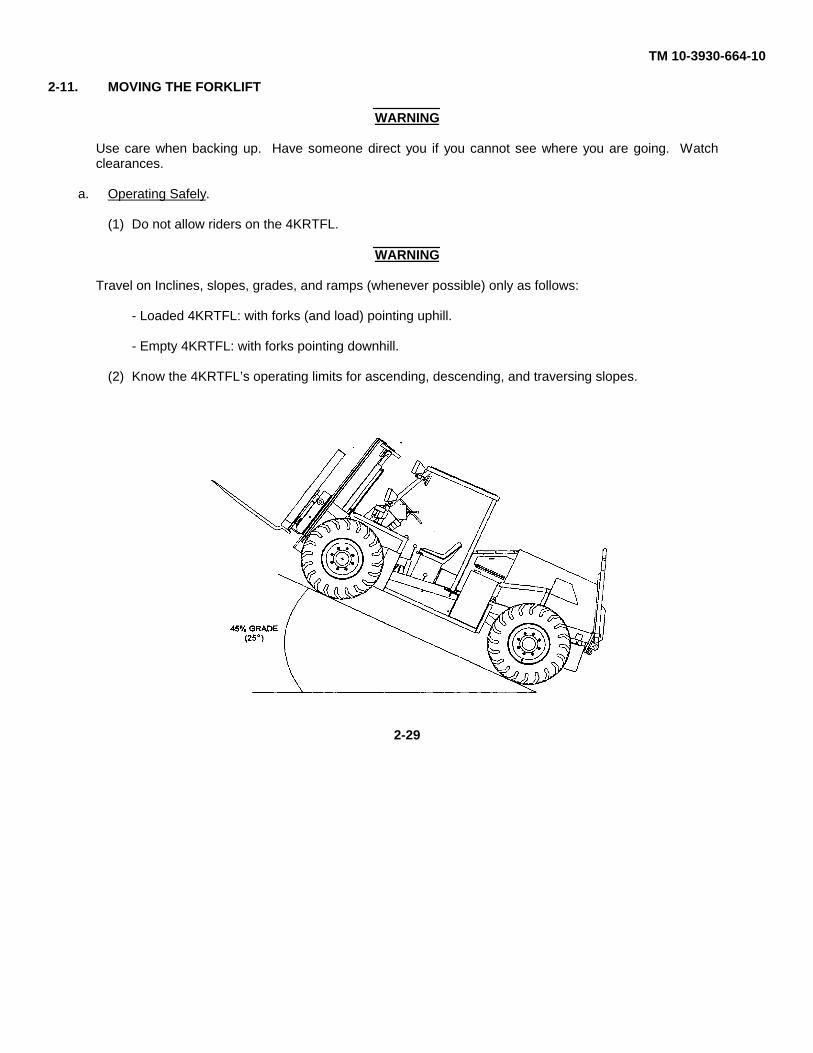
Travel on Inclines, slopes, grades, and ramps (whenever possible) only as follows:
- Loaded 4KRTFL: with forks (and load) pointing uphill.
- Empty 4KRTFL: with forks pointing downhill.
(2) Know the 4KRTFL’s operating limits for ascending, descending, and traversing slopes.
2-29
TM 10-3930-664-10
WARNING
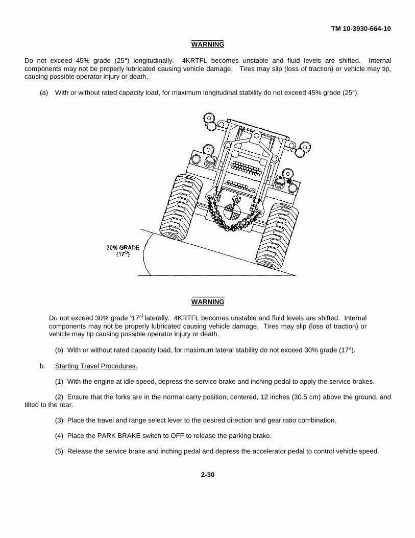
Do not exceed 45% grade (25°) longitudinally. 4KRTFL becomes unstable and fluid levels are shifted. Internalcomponents may not be properly lubricated causing vehicle damage. Tires may slip (loss of traction) or vehicle may tip,causing possible operator injury or death.
(a) With or without rated capacity load, for maximum longitudinal stability do not exceed 45% grade (25°).
WARNING
Do not exceed 30% grade (17°) laterally. 4KRTFL becomes unstable and fluid levels are shifted. Internalcomponents may not be properly lubricated causing vehicle damage. Tires may slip (loss of traction) orvehicle may tip causing possible operator injury or death.
(b) With or without rated capacity load, for maximum lateral stability do not exceed 30% grade (17°).
b. Starting Travel Procedures.
(1) With the engine at idle speed, depress the service brake and inching pedal to apply the service brakes.
(2) Ensure that the forks are in the normal carry position; centered, 12 inches (30.5 cm) above the ground, andtilted to the rear.
(3) Place the travel and range select lever to the desired direction and gear ratio combination.
(4) Place the PARK BRAKE switch to OFF to release the parking brake.
(5) Release the service brake and inching pedal and depress the accelerator pedal to control vehicle speed.
2-30
TM 10-3930-664-10
c. Changing Gear Ratios.
WARNING
Downshift at high speeds can cause equipment damage, loss of load off forks, and personal injury.
CAUTION
• Operating the 4KRTFL with a heavy load in F3 or R3 gear ratios will cause torque converter to slip excessivelyand the transmission may overheat.
• Upshifting and downshifting should be done in the normal sequence of speeds.
• The gears should be engaged only after reaching the top speed of the next lower gear. If necessary, the4KRTFL should be slowed by using the service brakes.
(1) To accelerate to desired speed, it may be necessary to shift to a higher gear ratio (F2 or F3, R2 or R3). Ashift to second or third speed forward (F2 or F3) from the next lower speed (F1 or F2) or to second or third speed reverse(R2 or R3) from the next lower speed (R1 or R2) can be made at full throttle, under load.
(2) When downshifting, do not over-rev the engine. Downshift to first or second speed in either direction maybe made at full throttle, under load providing the 4KRTFL is not exceeding the maximum speed attainable in the next lowergear ratio.
d. Changing Direction of Travel.
WARNING
Do not stop quickly. The load may drop off the forks causing damage or personal injury.
CAUTION
The 4KRTFL should be brought to a complete stop prior to shifting the travel and range select lever fromone direction to the other. The engine should be at idle speed when shifting from one direction to theother.
(1) Depress the service brake and inching pedal to bring the 4KRTFL to a complete stop.
(2) Move the travel and range select lever through neutral, "N", to the lowest gear ratio of the new direction oftravel.
(3) Release the service brake and inching pedal and depress the accelerator pedal to control 4KRTFL speedin the new direction.
e. Inching Procedure. The inching feature may be used to slowly move the 4KRTFL forward or backward. Toprecisely position the forks for lifting or depositing a load or to maneuver the vehicle into or out of confined areas, use thefollowing procedure.
NOTE
The inching feature operates by gradually declutching the transmission when the service brake andinching pedal is depressed or gradually permitting the clutches to engage when the pedal is released.Inching can be accomplished during a portion of pedal travel in either direction.
2-31
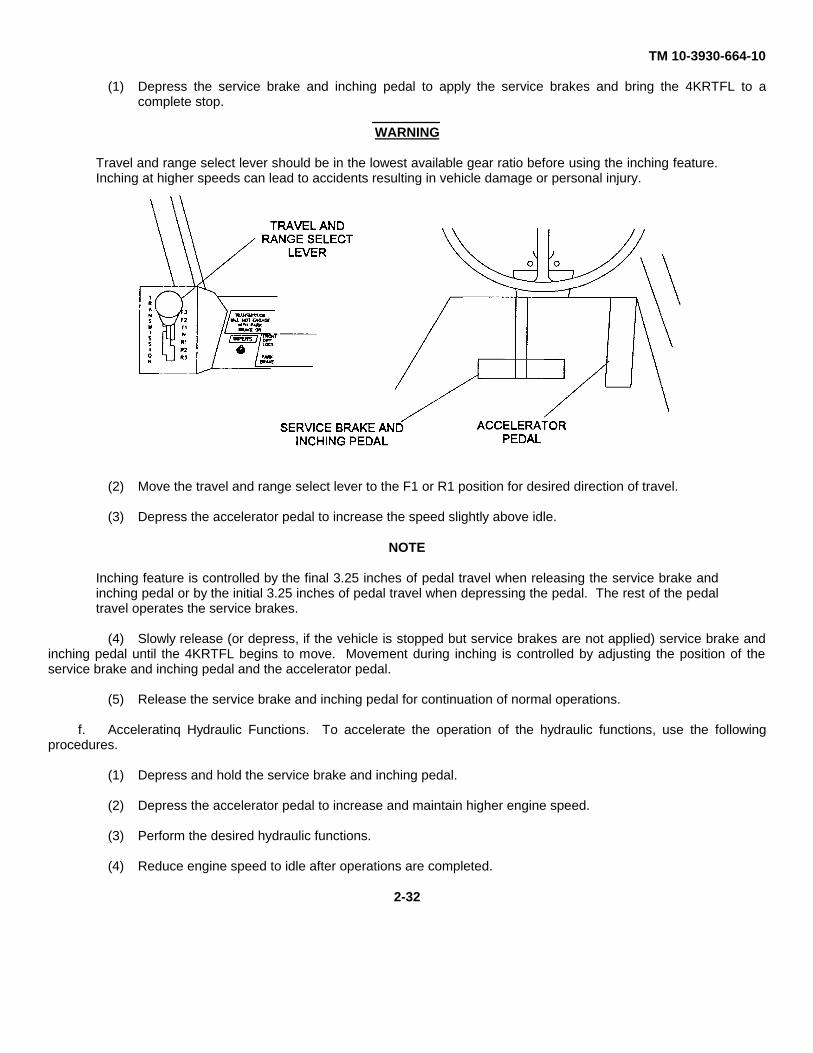
TM 10-3930-664-10
(1) Depress the service brake and inching pedal to apply the service brakes and bring the 4KRTFL to acomplete stop.
WARNING
Travel and range select lever should be in the lowest available gear ratio before using the inching feature.Inching at higher speeds can lead to accidents resulting in vehicle damage or personal injury.
(2) Move the travel and range select lever to the F1 or R1 position for desired direction of travel.
(3) Depress the accelerator pedal to increase the speed slightly above idle.
NOTE
Inching feature is controlled by the final 3.25 inches of pedal travel when releasing the service brake andinching pedal or by the initial 3.25 inches of pedal travel when depressing the pedal. The rest of the pedaltravel operates the service brakes.
(4) Slowly release (or depress, if the vehicle is stopped but service brakes are not applied) service brake andinching pedal until the 4KRTFL begins to move. Movement during inching is controlled by adjusting the position of theservice brake and inching pedal and the accelerator pedal.
(5) Release the service brake and inching pedal for continuation of normal operations.
f. Acceleratinq Hydraulic Functions. To accelerate the operation of the hydraulic functions, use the followingprocedures.
(1) Depress and hold the service brake and inching pedal.
(2) Depress the accelerator pedal to increase and maintain higher engine speed.
(3) Perform the desired hydraulic functions.
(4) Reduce engine speed to idle after operations are completed.
2-32
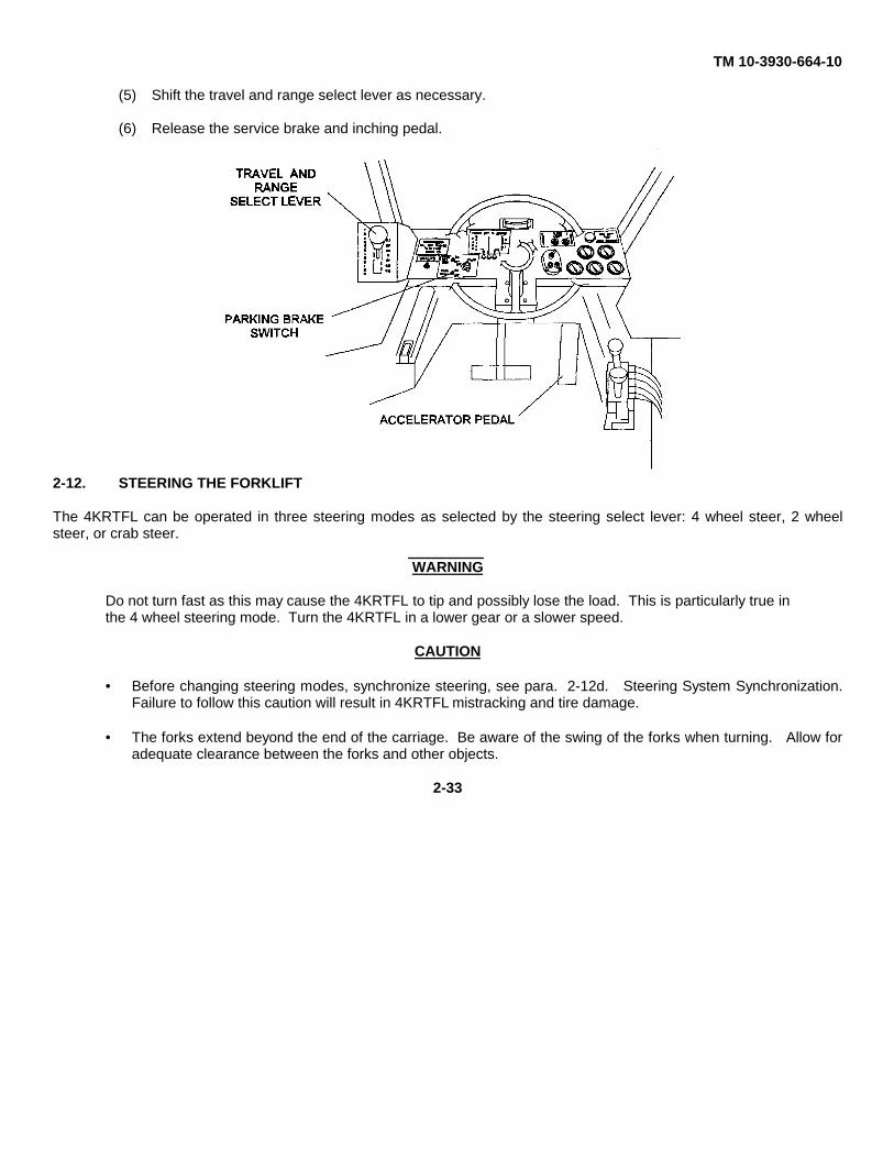
TM 10-3930-664-10
(5) Shift the travel and range select lever as necessary.
(6) Release the service brake and inching pedal.
2-12. STEERING THE FORKLIFT
The 4KRTFL can be operated in three steering modes as selected by the steering select lever: 4 wheel steer, 2 wheelsteer, or crab steer.
WARNING
Do not turn fast as this may cause the 4KRTFL to tip and possibly lose the load. This is particularly true inthe 4 wheel steering mode. Turn the 4KRTFL in a lower gear or a slower speed.
CAUTION
• Before changing steering modes, synchronize steering, see para. 2-12d. Steering System Synchronization.Failure to follow this caution will result in 4KRTFL mistracking and tire damage.
• The forks extend beyond the end of the carriage. Be aware of the swing of the forks when turning. Allow foradequate clearance between the forks and other objects.
2-33
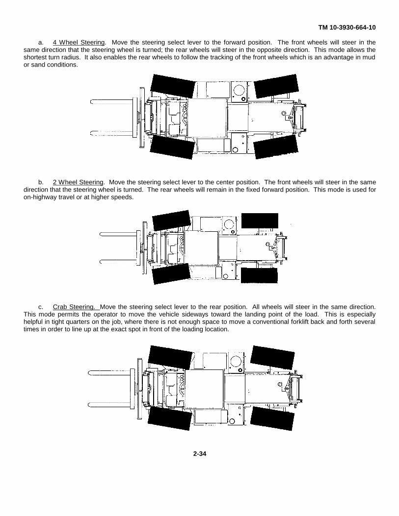
TM 10-3930-664-10
a. 4 Wheel Steering. Move the steering select lever to the forward position. The front wheels will steer in thesame direction that the steering wheel is turned; the rear wheels will steer in the opposite direction. This mode allows theshortest turn radius. It also enables the rear wheels to follow the tracking of the front wheels which is an advantage in mudor sand conditions.
b. 2 Wheel Steering. Move the steering select lever to the center position. The front wheels will steer in the samedirection that the steering wheel is turned. The rear wheels will remain in the fixed forward position. This mode is used foron-highway travel or at higher speeds.
c. Crab Steering. Move the steering select lever to the rear position. All wheels will steer in the same direction.This mode permits the operator to move the vehicle sideways toward the landing point of the load. This is especiallyhelpful in tight quarters on the job, where there is not enough space to move a conventional forklift back and forth severaltimes in order to line up at the exact spot in front of the loading location.
2-34
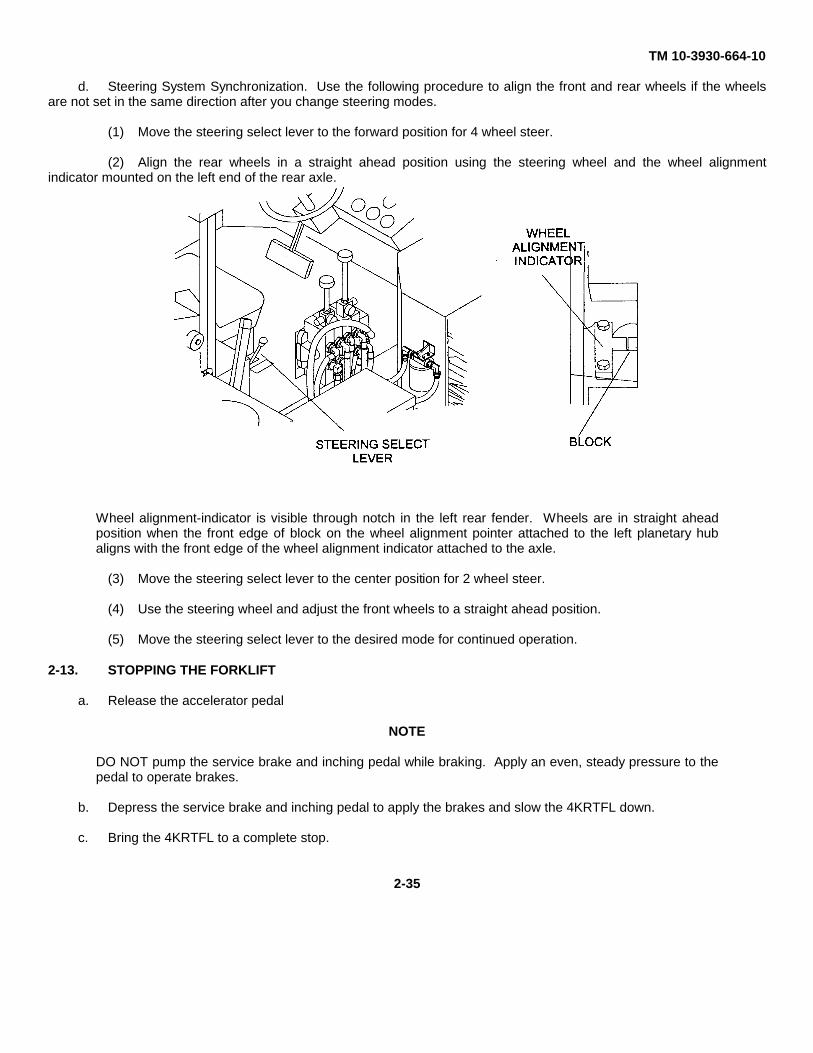
TM 10-3930-664-10
d. Steering System Synchronization. Use the following procedure to align the front and rear wheels if the wheelsare not set in the same direction after you change steering modes.
(1) Move the steering select lever to the forward position for 4 wheel steer.
(2) Align the rear wheels in a straight ahead position using the steering wheel and the wheel alignmentindicator mounted on the left end of the rear axle.
Wheel alignment-indicator is visible through notch in the left rear fender. Wheels are in straight aheadposition when the front edge of block on the wheel alignment pointer attached to the left planetary hubaligns with the front edge of the wheel alignment indicator attached to the axle.
(3) Move the steering select lever to the center position for 2 wheel steer.
(4) Use the steering wheel and adjust the front wheels to a straight ahead position.
(5) Move the steering select lever to the desired mode for continued operation.
2-13. STOPPING THE FORKLIFT
a. Release the accelerator pedal
NOTE
DO NOT pump the service brake and inching pedal while braking. Apply an even, steady pressure to thepedal to operate brakes.
b. Depress the service brake and inching pedal to apply the brakes and slow the 4KRTFL down.
c. Bring the 4KRTFL to a complete stop.
2-35
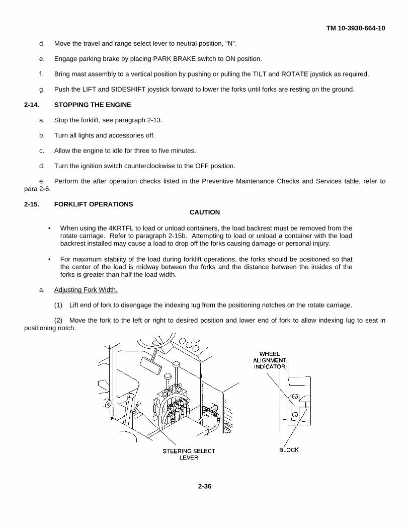
TM 10-3930-664-10
d. Move the travel and range select lever to neutral position, "N".
e. Engage parking brake by placing PARK BRAKE switch to ON position.
f. Bring mast assembly to a vertical position by pushing or pulling the TILT and ROTATE joystick as required.
g. Push the LIFT and SIDESHIFT joystick forward to lower the forks until forks are resting on the ground.
2-14. STOPPING THE ENGINE
a. Stop the forklift, see paragraph 2-13.
b. Turn all lights and accessories off.
c. Allow the engine to idle for three to five minutes.
d. Turn the ignition switch counterclockwise to the OFF position.
e. Perform the after operation checks listed in the Preventive Maintenance Checks and Services table, refer topara 2-6.
2-15. FORKLIFT OPERATIONSCAUTION
• When using the 4KRTFL to load or unload containers, the load backrest must be removed from therotate carriage. Refer to paragraph 2-15b. Attempting to load or unload a container with the loadbackrest installed may cause a load to drop off the forks causing damage or personal injury.
• For maximum stability of the load during forklift operations, the forks should be positioned so thatthe center of the load is midway between the forks and the distance between the insides of theforks is greater than half the load width.
a. Adjusting Fork Width.
(1) Lift end of fork to disengage the indexing lug from the positioning notches on the rotate carriage.
(2) Move the fork to the left or right to desired position and lower end of fork to allow indexing lug to seat inpositioning notch.
2-36
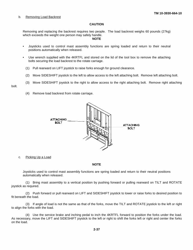
TM 10-3930-664-10b. Removing Load Backrest
CAUTION
Removing and replacing the backrest requires two people. The load backrest weighs 60 pounds (27kg)which exceeds the weight one person may safely handle.
NOTE
• Joysticks used to control mast assembly functions are spring loaded and return to their neutralpositions automatically when released.
• Use wrench supplied with the 4KRTFL and stored on the lid of the tool box to remove the attachingbolts securing the load backrest to the rotate carriage.
(1) Pull rearward on LIFT joystick to raise forks enough for ground clearance.
(2) Move SIDESHIFT joystick to the left to allow access to the left attaching bolt. Remove left attaching bolt.
(3) Move SIDESHIFT joystick to the right to allow access to the right attaching bolt. Remove right attachingbolt.
(4) Remove load backrest from rotate carriage.
c. Picking Up a Load
NOTE
Joysticks used to control mast assembly functions are spring loaded and return to their neutral positionsautomatically when released.
(1) Bring mast assembly to a vertical position by pushing forward or pulling rearward on TILT and ROTATEjoystick as required.
(2) Push forward or pull rearward on LIFT and SIDESHIFT joystick to lower or raise forks to desired position tofit beneath the load.
(3) If angle of load is not the same as that of the forks, move the TILT and ROTATE joystick to the left or rightto align the forks with the load.
(4) Use the service brake and inching pedal to inch the 4KRTFL forward to position the forks under the load.As necessary, move the LIFT and SIDESHIFT joystick to the left or right to shift the forks left or right and center the forkson the load.
2-37
TM 10-3930-664-10
(5) Pull the LIFT and SIDESHIFT joystick to the rear to raise load to desired height for removal from stack orfor transport.
(6) Pull the TILT and ROTATE joystick to the rear to tilt mast rearward enough to safely transport the loadwithout danger of the load sliding off the forks.
d. Transporting a Load.
WARNING
Always operate the 4KRTFL at a safe speed. Know the rated capacity of the 4KRTFL and do not overloadit. Avoid sudden stops to prevent the load from sliding forward and off the forks. NEVER tilt the mastassembly forward beyond the vertical position except to deposit the load on a stack, trailer, or ground.
(1) To clear a stack or exit a container, place travel and range select lever in R1 and use the service brake andinching pedal to Inch the 4KRTFL rearward.
(2) With load tilted rearward and lowered to normal carry height of 12 inches (30 cm) above the ground,transport the load at a safe speed for the type of load and terrain.
(3) As necessary to compensate for uneven loads or sloping terrain, move the TILT AND ROTATE joystick tothe left or right to rotate forks to desired position.
e. Depositing a Load.
(1) Bring the mast assembly to a vertical position by pushing the TILT AND ROTATE joystick forward.
(2) As necessary, align the forks with the stack, trailer, or ground by moving the TILT AND ROTATE joystickleft or right to rotate the forks to the desired position.
(3) As necessary, move the LIFT AND SIDESHIFT joystick left or right to shift the load left or right to place theload in the proper position for unloading.
(4) If the load is to be placed on a stack or a level higher than the transport level, raise the fork to the desiredheight by pulling the LIFT AND SIDESHIFT joystick to the rear.
(5) Use the service brake and inching pedal to inch the 4KRTFL forward to the location where the load is to beplaced.
(6) Push the LIFT AND SIDESHIFT joystick forward to lower the load until it rests on the stack, trailer, orground.
(7) Place the travel and range selector lever in the R1 position and use service brake and inching pedal toback 4KRTFL away from the load.
2-38
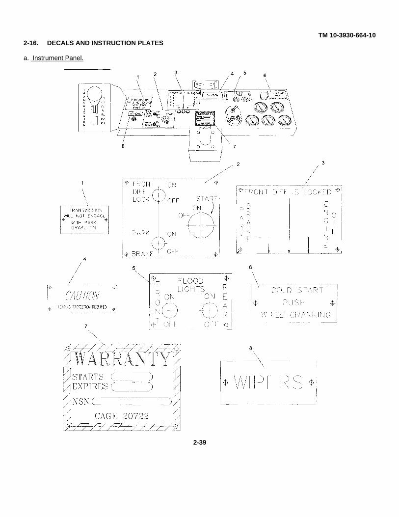
TM 10-3930-664-102-16. DECALS AND INSTRUCTION PLATES
a. Instrument Panel.
2-39
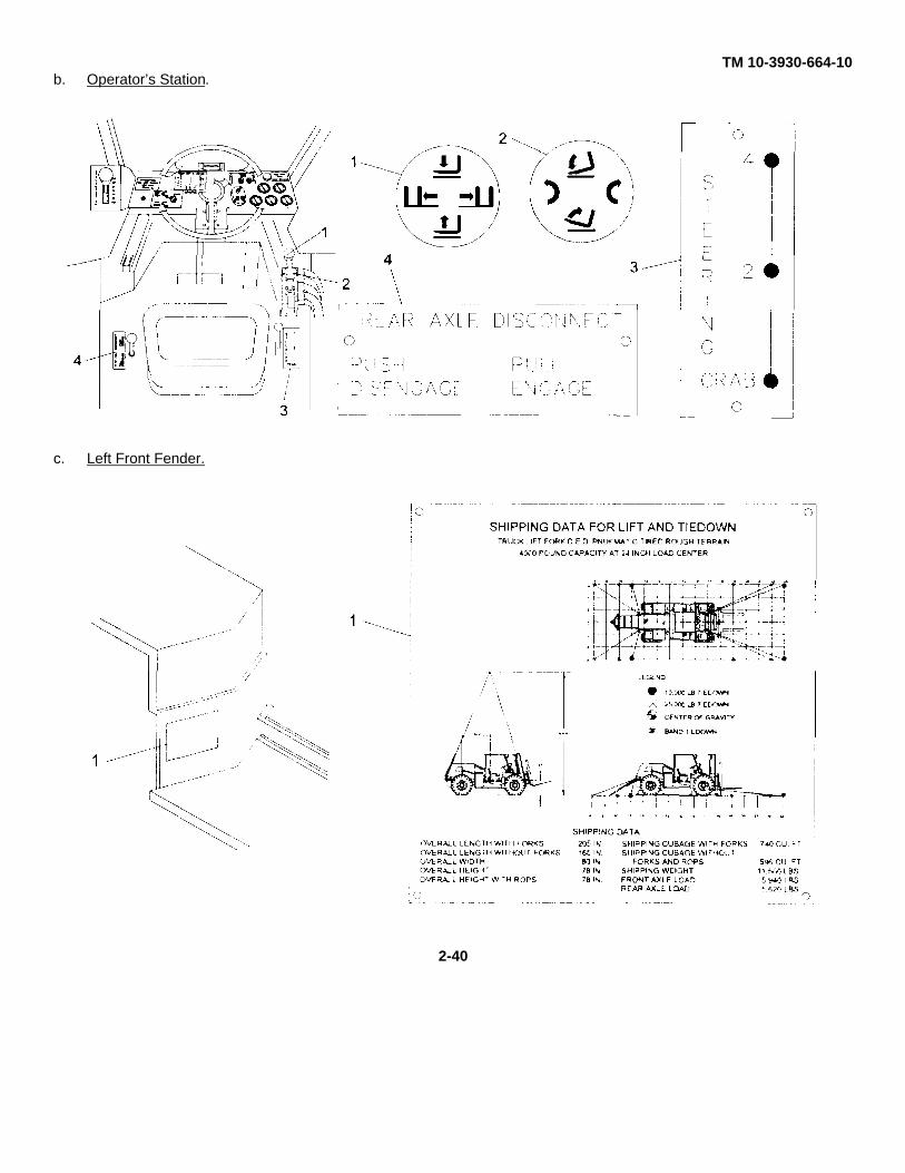
TM 10-3930-664-10b. Operator’s Station.
c. Left Front Fender.
2-40
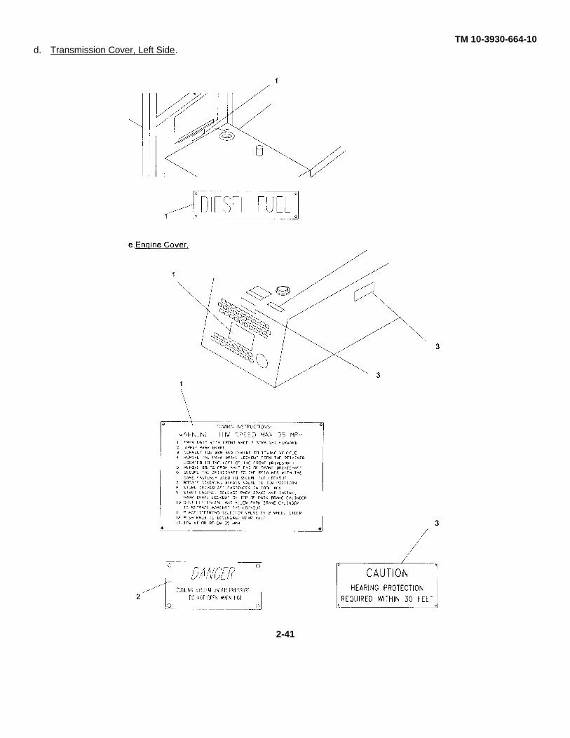
TM 10-3930-664-10d. Transmission Cover, Left Side.
2-41
PAGE 2-42This page was not available from the proponent or the
Publication Distribution Center at the time of the CD release.Please refer to your paper or microfiche copy as appropriate.
NOT DIGITIZED
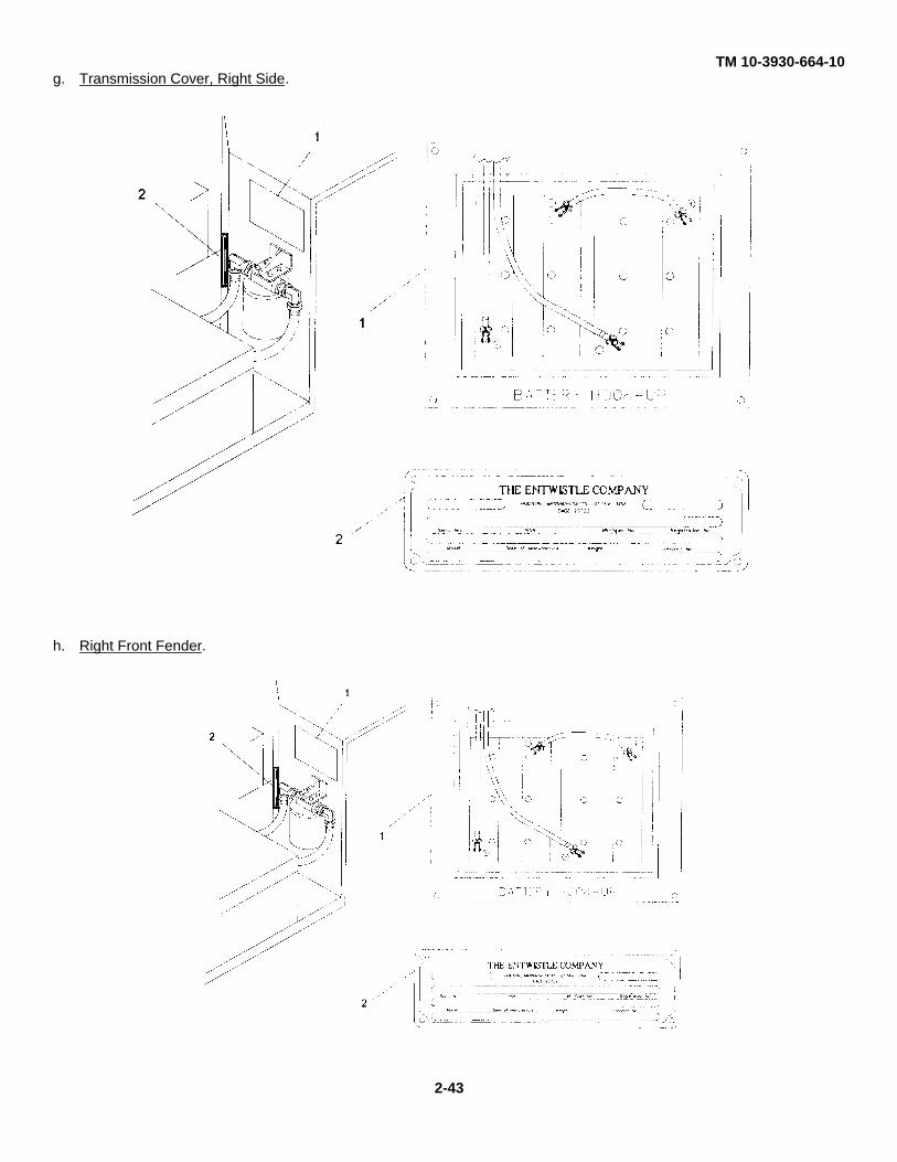
TM 10-3930-664-10g. Transmission Cover, Right Side.
h. Right Front Fender.
2-43
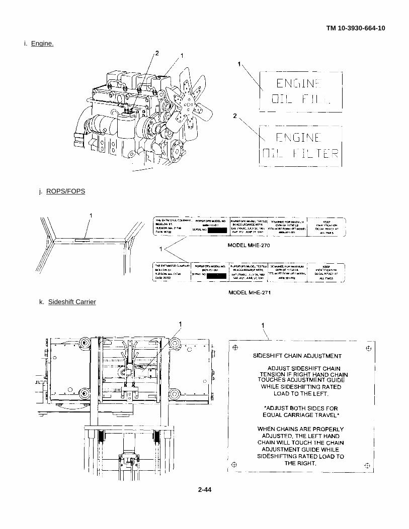
TM 10-3930-664-10
i. Engine.
j. ROPS/FOPS
k. Sideshift Carrier
2-44
TM 10-3930-664-10SECTION IV. Operation Under Unusual Conditions
2-17. GENERAL
This section provides the operator with additional instructions for operating in various environments and emergencysituations.
2-18. OPERATION IN EXTREME MOIST HEAT
At Parking or Halt.
(1) If possible, park the 4KRTFL under shelter.
(2) Dry the seat and wiring to prevent the formation of mildew.
(3) Keep the fuel tank full at all times to prevent condensation from forming in the tank.
(4) Contact organizational Maintenance to check all points of lubrication according to LO10-3930-664-12.
2-19. OPERATION IN EXTREME DRY HEAT. (Refer to FM90-3, DESERT OPERATIONS)
a. Preparation. Precautions must be taken to avoid overheating.
(1) Contact Organizational Maintenance to drain, flush and refill cooling system.
(2) Contact Organizational Maintenance to lubricate the 4KRTFL with correct grade of lubricants in accordancewith Lubrication Order, LO10-3930-664-12.
b. Operation.
(1) Check the water temperature and transmission oil temperature gauges at frequent intervals.
(2) Check the air cleaner indicator frequently. Service the filter as often as required.
c. At Halt or Parking. Park the 4KRTFL in shaded area, if possible. Cover seat, steering wheel, controls, andgauges to protect them from direct heating by the sun.
2-20. OPERATION IN EXTREME COLD
a. Preparations. Extensive preparation of mechanical equipment is required when extreme cold weather isanticipated. The following steps will help protect the vehicle against subfreezing temperatures.
(1) Contact Organizational Maintenance to prepare the cooling system by draining and then refilling withantifreeze appropriate for anticipated temperatures. Refer to Appendix D and FM 4-367.
(2) Contact Organizational Maintenance to change the engine lubricating oil to the grade called for in LO10-3930-664-12 for cold weather operation.
b. Starting the Engine.
(1) Try starting the engine using the procedure given in paragraph 2-10.
2-45
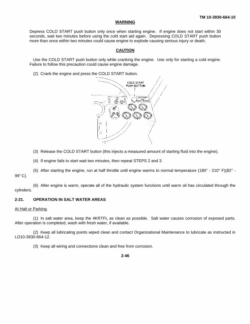
TM 10-3930-664-10WARNING
Depress COLD START push button only once when starting engine. If engine does not start within 30seconds, wait two minutes before using the cold start aid again. Depressing COLD START push buttonmore than once within two minutes could cause engine to explode causing serious injury or death.
CAUTION
Use the COLD START push button only while cranking the engine. Use only for starting a cold engine.Failure to follow this precaution could cause engine damage.
(2) Crank the engine and press the COLD START button.
(3) Release the COLD START button (this injects a measured amount of starting fluid into the engine).
(4) If engine fails to start wait two minutes, then repeat STEPS 2 and 3.
(5) After starting the engine, run at half throttle until engine warms to normal temperature (180° - 210° F)(82° -99° C).
(6) After engine is warm, operate all of the hydraulic system functions until warm oil has circulated through thecylinders.
2-21. OPERATION IN SALT WATER AREAS
At Halt or Parking.
(1) In salt water area, keep the 4KRTFL as clean as possible. Salt water causes corrosion of exposed parts.After operation is completed, wash with fresh water, if available.
(2) Keep all lubricating points wiped clean and contact Organizational Maintenance to lubricate as instructed inLO10-3930-664-12.
(3) Keep all wiring and connections clean and free from corrosion.
2-46
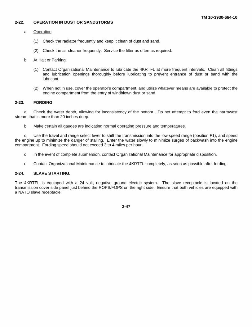
TM 10-3930-664-102-22. OPERATION IN DUST OR SANDSTORMS
a. Operation.
(1) Check the radiator frequently and keep it clean of dust and sand.
(2) Check the air cleaner frequently. Service the filter as often as required.
b. At Halt or Parking.
(1) Contact Organizational Maintenance to lubricate the 4KRTFL at more frequent intervals. Clean all fittingsand lubrication openings thoroughly before lubricating to prevent entrance of dust or sand with thelubricant.
(2) When not in use, cover the operator’s compartment, and utilize whatever means are available to protect theengine compartment from the entry of windblown dust or sand.
2-23. FORDING
a. Check the water depth, allowing for inconsistency of the bottom. Do not attempt to ford even the narroweststream that is more than 20 inches deep.
b. Make certain all gauges are indicating normal operating pressure and temperatures.
c. Use the travel and range select lever to shift the transmission into the low speed range (position F1), and speedthe engine up to minimize the danger of stalling. Enter the water slowly to minimize surges of backwash into the enginecompartment. Fording speed should not exceed 3 to 4 miles per hour.
d. In the event of complete submersion, contact Organizational Maintenance for appropriate disposition.
e. Contact Organizational Maintenance to lubricate the 4KRTFL completely, as soon as possible after fording.
2-24. SLAVE STARTING.
The 4KRTFL is equipped with a 24 volt, negative ground electric system. The slave receptacle is located on thetransmission cover side panel just behind the ROPS/FOPS on the right side. Ensure that both vehicles are equipped witha NATO slave receptacle.
2-47
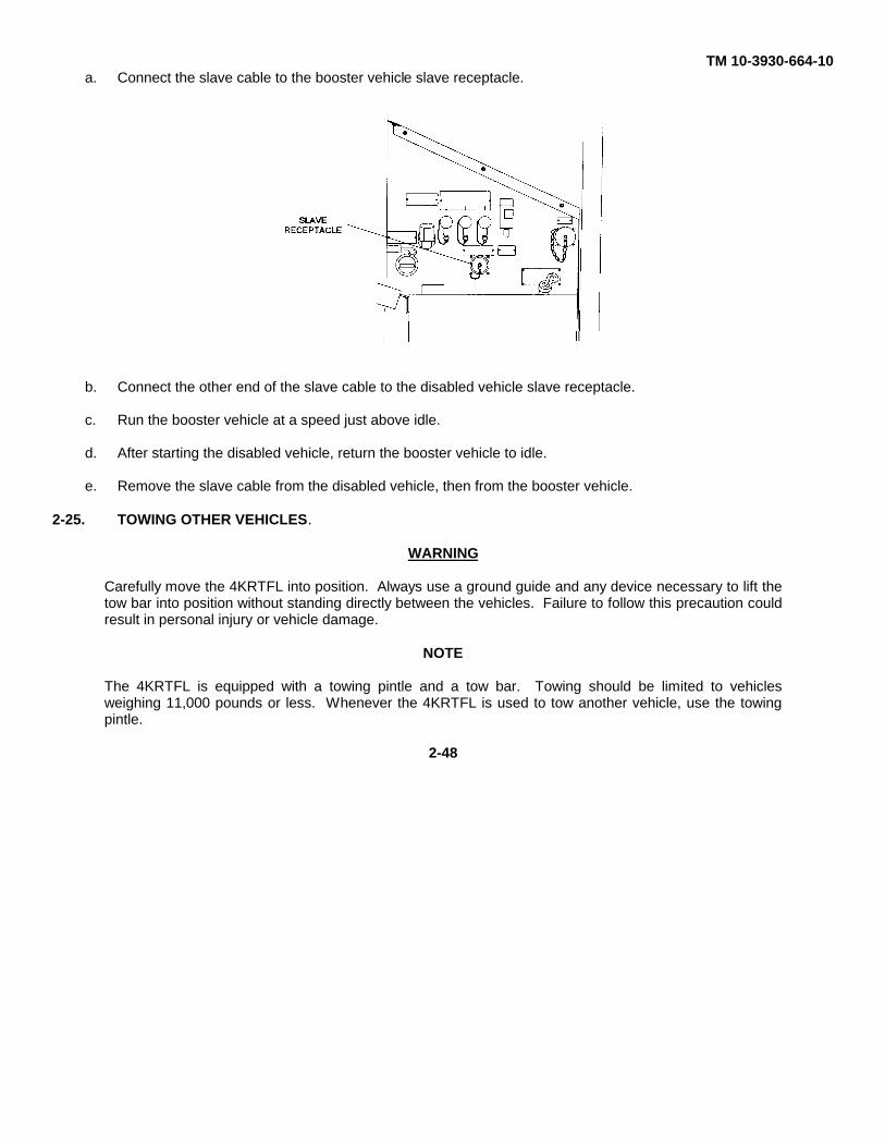
TM 10-3930-664-10a. Connect the slave cable to the booster vehicle slave receptacle.
b. Connect the other end of the slave cable to the disabled vehicle slave receptacle.
c. Run the booster vehicle at a speed just above idle.
d. After starting the disabled vehicle, return the booster vehicle to idle.
e. Remove the slave cable from the disabled vehicle, then from the booster vehicle.
2-25. TOWING OTHER VEHICLES.
WARNING
Carefully move the 4KRTFL into position. Always use a ground guide and any device necessary to lift thetow bar into position without standing directly between the vehicles. Failure to follow this precaution couldresult in personal injury or vehicle damage.
NOTE
The 4KRTFL is equipped with a towing pintle and a tow bar. Towing should be limited to vehiclesweighing 11,000 pounds or less. Whenever the 4KRTFL is used to tow another vehicle, use the towingpintle.
2-48
TM 10-3930-664-10
a. Position the 4KRTFL so that the tow bar from the disabled vehicle can be attached to the towing pintle.
NOTE
Parking brake is automatically applied when engine is not running unless park brake lockout has beeninstalled.
b. Stop the engine. See para 2-14.
WARNING
When hooking or unhooking the tow bar lunette from a disabled vehicle, set the parking brake or chockthe wheels of the disabled vehicle before hooking or unhooking the tow bar. Otherwise, disabled vehiclemay move, causing injury, death, or damage.
c. Set the parking brake or chock the wheels of the vehicle to be towed.
d. Attach the tow bar lunette from the disabled vehicle to the towing pintle of the 4KRTFL.
e. Release the parking brake or remove the chocks from the wheels of the disabled vehicle.
f. Proceed to tow with caution.
2-26. TOWING THE 4KRTFL.
WARNING
Carefully move the towing vehicle into position. Always use a ground guide and any device necessary tolift the tow bar into position without standing directly between the vehicles. Failure to follow this precautioncould result in personal injury or vehicle damage.
2-49
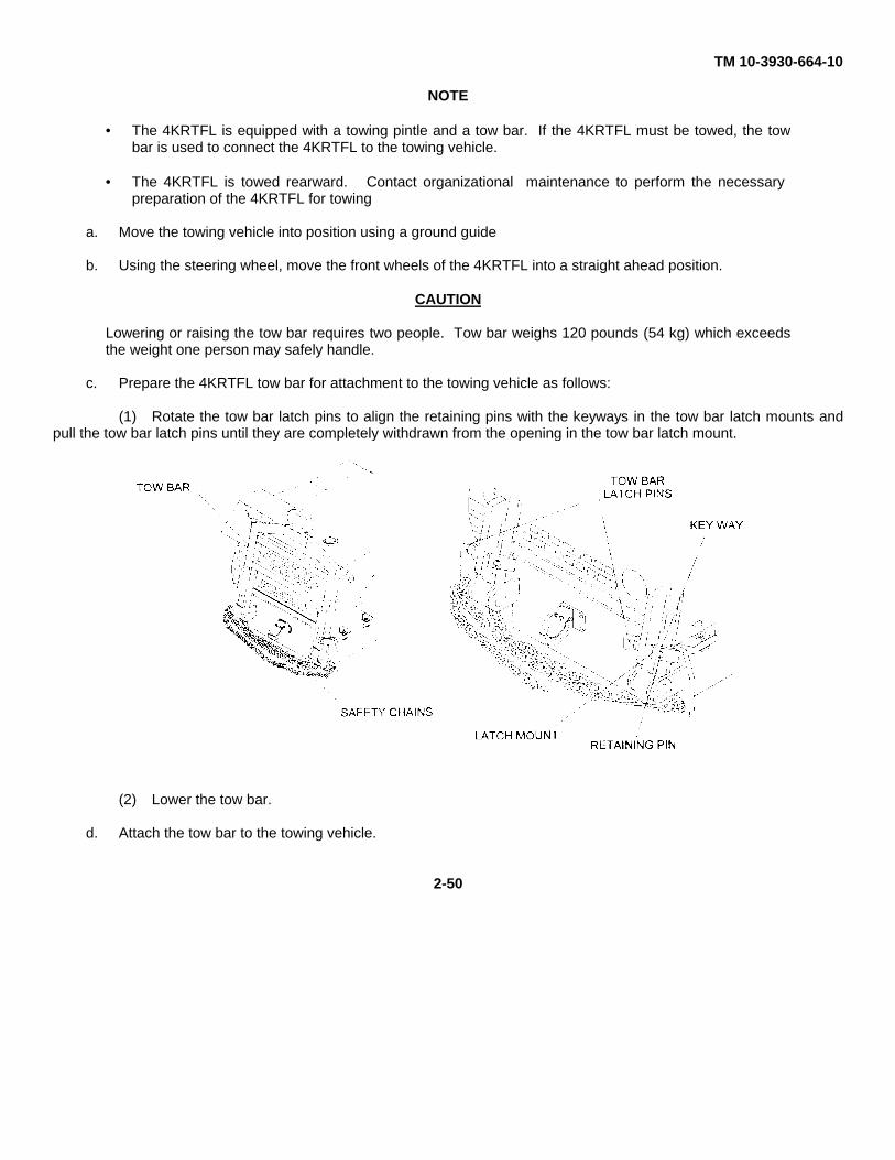
TM 10-3930-664-10
NOTE
• The 4KRTFL is equipped with a towing pintle and a tow bar. If the 4KRTFL must be towed, the towbar is used to connect the 4KRTFL to the towing vehicle.
• The 4KRTFL is towed rearward. Contact organizational maintenance to perform the necessarypreparation of the 4KRTFL for towing
a. Move the towing vehicle into position using a ground guide
b. Using the steering wheel, move the front wheels of the 4KRTFL into a straight ahead position.
CAUTION
Lowering or raising the tow bar requires two people. Tow bar weighs 120 pounds (54 kg) which exceedsthe weight one person may safely handle.
c. Prepare the 4KRTFL tow bar for attachment to the towing vehicle as follows:
(1) Rotate the tow bar latch pins to align the retaining pins with the keyways in the tow bar latch mounts andpull the tow bar latch pins until they are completely withdrawn from the opening in the tow bar latch mount.
(2) Lower the tow bar.
d. Attach the tow bar to the towing vehicle.
2-50
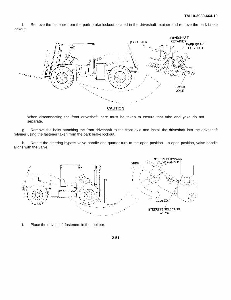
TM 10-3930-664-10
f. Remove the fastener from the park brake lockout located in the driveshaft retainer and remove the park brakelockout.
CAUTION
When disconnecting the front driveshaft, care must be taken to ensure that tube and yoke do notseparate.
g. Remove the bolts attaching the front driveshaft to the front axle and install the driveshaft into the driveshaftretainer using the fastener taken from the park brake lockout.
h. Rotate the steering bypass valve handle one-quarter turn to the open position. In open position, valve handlealigns with the valve.
i. Place the driveshaft fasteners in the tool box
2-51
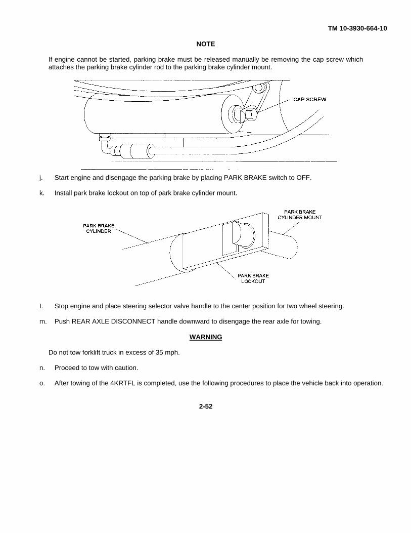
TM 10-3930-664-10
NOTE
If engine cannot be started, parking brake must be released manually be removing the cap screw whichattaches the parking brake cylinder rod to the parking brake cylinder mount.
j. Start engine and disengage the parking brake by placing PARK BRAKE switch to OFF.
k. Install park brake lockout on top of park brake cylinder mount.
I. Stop engine and place steering selector valve handle to the center position for two wheel steering.
m. Push REAR AXLE DISCONNECT handle downward to disengage the rear axle for towing.
WARNING
Do not tow forklift truck in excess of 35 mph.
n. Proceed to tow with caution.
o. After towing of the 4KRTFL is completed, use the following procedures to place the vehicle back into operation.
2-52
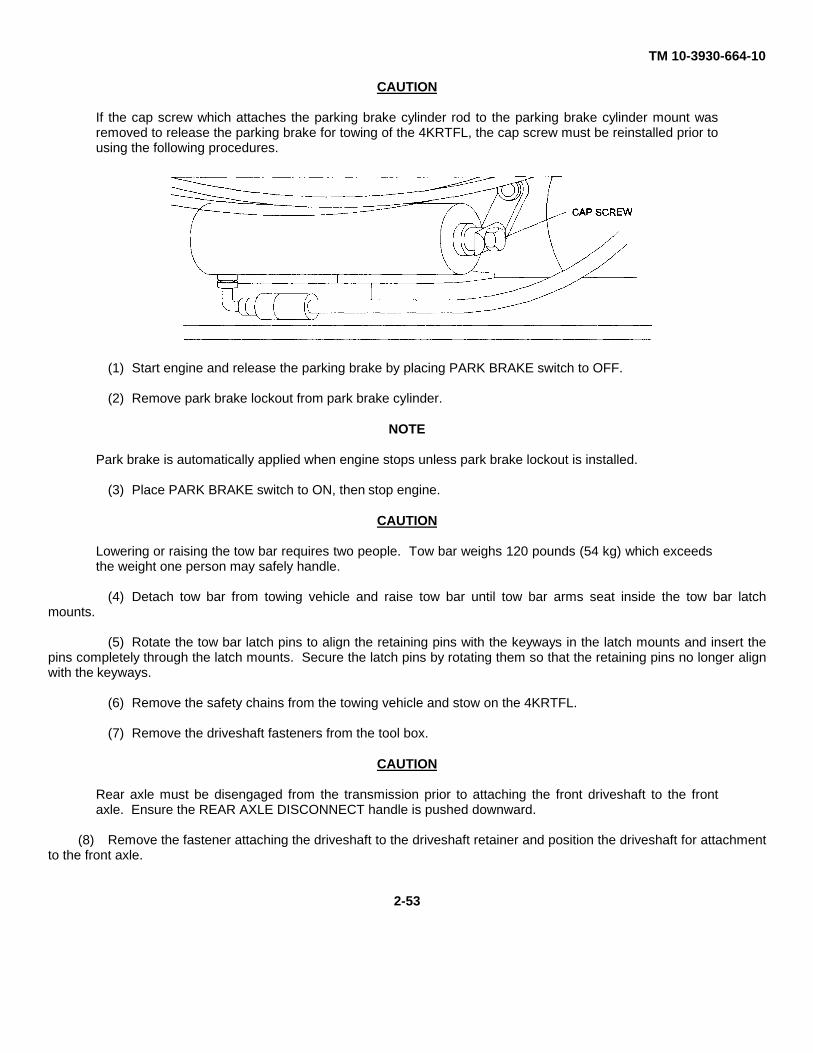
TM 10-3930-664-10
CAUTION
If the cap screw which attaches the parking brake cylinder rod to the parking brake cylinder mount wasremoved to release the parking brake for towing of the 4KRTFL, the cap screw must be reinstalled prior tousing the following procedures.
(1) Start engine and release the parking brake by placing PARK BRAKE switch to OFF.
(2) Remove park brake lockout from park brake cylinder.
NOTE
Park brake is automatically applied when engine stops unless park brake lockout is installed.
(3) Place PARK BRAKE switch to ON, then stop engine.
CAUTION
Lowering or raising the tow bar requires two people. Tow bar weighs 120 pounds (54 kg) which exceedsthe weight one person may safely handle.
(4) Detach tow bar from towing vehicle and raise tow bar until tow bar arms seat inside the tow bar latchmounts.
(5) Rotate the tow bar latch pins to align the retaining pins with the keyways in the latch mounts and insert thepins completely through the latch mounts. Secure the latch pins by rotating them so that the retaining pins no longer alignwith the keyways.
(6) Remove the safety chains from the towing vehicle and stow on the 4KRTFL.
(7) Remove the driveshaft fasteners from the tool box.
CAUTION
Rear axle must be disengaged from the transmission prior to attaching the front driveshaft to the frontaxle. Ensure the REAR AXLE DISCONNECT handle is pushed downward.
(8) Remove the fastener attaching the driveshaft to the driveshaft retainer and position the driveshaft for attachmentto the front axle.
2-53
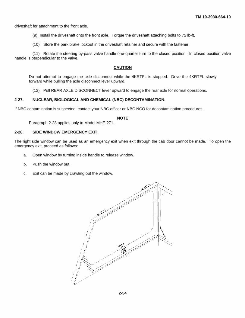
TM 10-3930-664-10
driveshaft for attachment to the front axle.
(9) Install the driveshaft onto the front axle. Torque the driveshaft attaching bolts to 75 lb-ft.
(10) Store the park brake lockout in the driveshaft retainer and secure with the fastener.
(11) Rotate the steering by-pass valve handle one-quarter turn to the closed position. In closed position valvehandle is perpendicular to the valve.
CAUTION
Do not attempt to engage the axle disconnect while the 4KRTFL is stopped. Drive the 4KRTFL slowlyforward while pulling the axle disconnect lever upward.
(12) Pull REAR AXLE DISCONNECT lever upward to engage the rear axle for normal operations.
2-27. NUCLEAR, BIOLOGICAL AND CHEMICAL (NBC) DECONTAMINATION.
If NBC contamination is suspected, contact your NBC officer or NBC NCO for decontamination procedures.
NOTEParagraph 2-28 applies only to Model MHE-271.
2-28. SIDE WINDOW EMERGENCY EXIT.
The right side window can be used as an emergency exit when exit through the cab door cannot be made. To open theemergency exit, proceed as follows:
a. Open window by turning inside handle to release window.
b. Push the window out.
c. Exit can be made by crawling out the window.
2-54
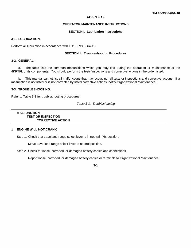
TM 10-3930-664-10CHAPTER 3
OPERATOR MAINTENANCE INSTRUCTIONS
SECTION I. Lubrication Instructions
3-1. LUBRICATION.
Perform all lubrication in accordance with LO10-3930-664-12.
SECTION II. Troubleshooting Procedures
3-2. GENERAL.
a. The table lists the common malfunctions which you may find during the operation or maintenance of the4KRTFL or its components. You should perform the tests/inspections and corrective actions in the order listed.
b. This manual cannot list all malfunctions that may occur, nor all tests or inspections and corrective actions. If amalfunction is not listed or is not corrected by listed corrective actions, notify Organizational Maintenance.
3-3. TROUBLESHOOTING.
Refer to Table 3-1 for troubleshooting procedures.
Table 3-1. Troubleshooting
MALFUNCTIONTEST OR INSPECTION
CORRECTIVE ACTION
1 ENGINE WILL NOT CRANK
Step 1. Check that travel and range select lever is in neutral, (N), position.
Move travel and range select lever to neutral position.
Step 2. Check for loose, corroded, or damaged battery cables and connections.
Report loose, corroded, or damaged battery cables or terminals to Organizational Maintenance.
3-1
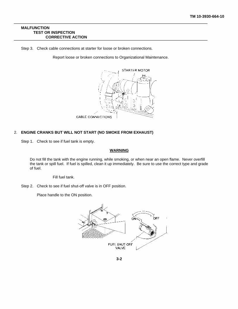
TM 10-3930-664-10
MALFUNCTIONTEST OR INSPECTION
CORRECTIVE ACTION
Step 3. Check cable connections at starter for loose or broken connections.
Report loose or broken connections to Organizational Maintenance.
2. ENGINE CRANKS BUT WILL NOT START (NO SMOKE FROM EXHAUST)
Step 1. Check to see if fuel tank is empty.
WARNING
Do not fill the tank with the engine running, while smoking, or when near an open flame. Never overfillthe tank or spill fuel. If fuel is spilled, clean it up immediately. Be sure to use the correct type and gradeof fuel.
Fill fuel tank.
Step 2. Check to see if fuel shut-off valve is in OFF position.
Place handle to the ON position.
3-2
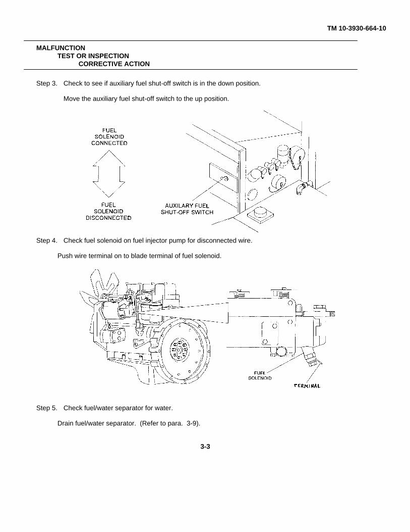
TM 10-3930-664-10
MALFUNCTIONTEST OR INSPECTION
CORRECTIVE ACTION
Step 3. Check to see if auxiliary fuel shut-off switch is in the down position.
Move the auxiliary fuel shut-off switch to the up position.
Step 4. Check fuel solenoid on fuel injector pump for disconnected wire.
Push wire terminal on to blade terminal of fuel solenoid.
Step 5. Check fuel/water separator for water.
Drain fuel/water separator. (Refer to para. 3-9).
3-3
TM 10-3930-664-10
MALFUNCTIONTEST OR INSPECTION
CORRECTIVE ACTION
3. ENGINE HARD TO START OR WILL NOT START (EXHAUST SMOKE PRESENT)
Step 1 Check the ambient temperature.
Use the cold start push button when the ambient temperature Is 32° F 0° C) or lower.
(Refer to para 2-20)
Step 2. Check air cleaner restriction indicator to see if red flag shows (indicates that air cleaner is clogged )
Service the air cleaner. (Refer to para 3-10.)
Step 3. Check to see if any fuel lines are damaged.
Report damaged fuel lines to Organizational Maintenance.
4. ENGINE STARTS BUT WILL NOT RUN
Step 1. Check fuel/water separator for water.
Drain fuel/water separator. (Refer to para 3-9.)
Step 2. Check to see if any fuel lines are damaged.
Report damaged fuel lines to Organizational Maintenance.
5. ENGINE MISFIRES OR RUNS ROUGH
Step 1. Check to see if fuel tank is low or empty.
WARNING
Do not fill the tank with the engine running, while smoking, or when near an open flame. Never overfill thetank or spill fuel. If fuel is spilled, clean it up immediately. Be sure to use the correct type and grade offuel.
Fill fuel tank.
Step 2. Check to see if any moisture is present in water separator.
Drain the water separator. (Refer to para. 3-9.)
Step 3. Check for black or gray exhaust smoke. Plugged or dirty intake system.
Service air cleaner. (Refer to para 3-10).
Step 4. Check for white or blue smoke. Indicates engine is cold.
Allow engine to warm up.
3-4
TM 10-3930-664-10
MALFUNCTIONTEST OR INSPECTION
CORRECTIVE ACTION
Step 5. Check for leaks in fuel lines and injectors.
Report leaks to Organizational Maintenance.
6. LOW ENGINE POWER
Step 1. Check if engine oil level is above FULL mark.
Report over filled engine oil level to Organizational Maintenance.
Step 2. Check air cleaner restriction indicator to see if red flag shows (indicates that air cleaner is clogged.)
Service air cleaner. (Refer to para 3-10).
Step 3. Check the exhaust pipe for obstruction.
Remove any obstructions.
7. ENGINE OVERHEATS
WARNING
Don’t remove the radiator cap when the engine is hot; hot steaming gases can escape and bum you. Useextreme care when removing the radiator pressure cap. The sudden release of pressure can cause asteam flash which could seriously injure you. Slowly loosen cap to the first stop to relieve pressure beforeremoving cap completely. After use, tighten cap securely.
Step 1. Check for low coolant level.
Add coolant as required. (Refer to para. 3-8.)
Step 2. Check radiator hoses for leaks or collapse.
Report collapsed hoses or leaks to Organizational Maintenance.
WARNING
The engine, radiator, and oil cooler can be extremely hot. Contacting exposed skin to these areas couldresult in severe bums.
Step 3. Check radiator for leaks or obstruction by debris.
Clean debris from radiator fins. Report leaks to Organizational Maintenance
3-5
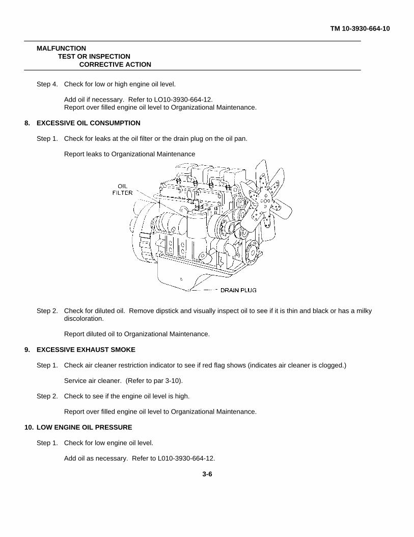
TM 10-3930-664-10
MALFUNCTIONTEST OR INSPECTION
CORRECTIVE ACTION
Step 4. Check for low or high engine oil level.
Add oil if necessary. Refer to LO10-3930-664-12.Report over filled engine oil level to Organizational Maintenance.
8. EXCESSIVE OIL CONSUMPTION
Step 1. Check for leaks at the oil filter or the drain plug on the oil pan.
Report leaks to Organizational Maintenance
Step 2. Check for diluted oil. Remove dipstick and visually inspect oil to see if it is thin and black or has a milkydiscoloration.
Report diluted oil to Organizational Maintenance.
9. EXCESSIVE EXHAUST SMOKE
Step 1. Check air cleaner restriction indicator to see if red flag shows (indicates air cleaner is clogged.)
Service air cleaner. (Refer to par 3-10).
Step 2. Check to see if the engine oil level is high.
Report over filled engine oil level to Organizational Maintenance.
10. LOW ENGINE OIL PRESSURE
Step 1. Check for low engine oil level.
Add oil as necessary. Refer to L010-3930-664-12.
3-6
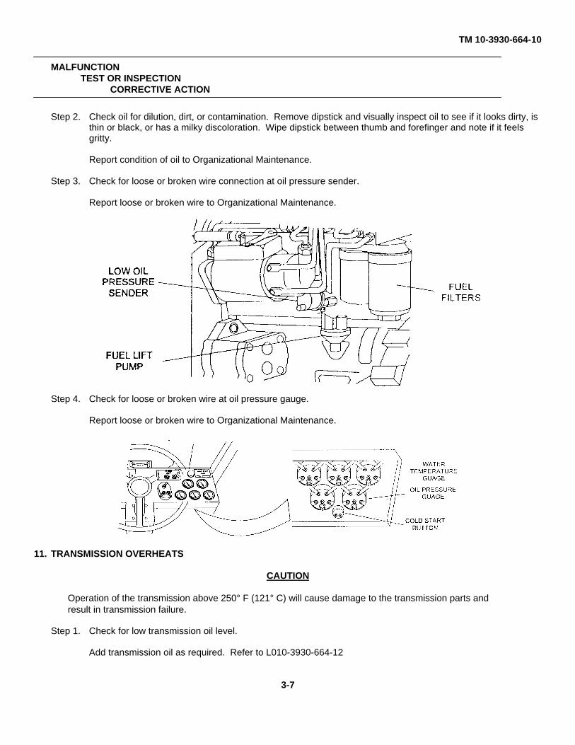
TM 10-3930-664-10
MALFUNCTIONTEST OR INSPECTION
CORRECTIVE ACTION
Step 2. Check oil for dilution, dirt, or contamination. Remove dipstick and visually inspect oil to see if it looks dirty, isthin or black, or has a milky discoloration. Wipe dipstick between thumb and forefinger and note if it feelsgritty.
Report condition of oil to Organizational Maintenance.
Step 3. Check for loose or broken wire connection at oil pressure sender.
Report loose or broken wire to Organizational Maintenance.
Step 4. Check for loose or broken wire at oil pressure gauge.
Report loose or broken wire to Organizational Maintenance.
11. TRANSMISSION OVERHEATS
CAUTION
Operation of the transmission above 250° F (121° C) will cause damage to the transmission parts andresult in transmission failure.
Step 1. Check for low transmission oil level.
Add transmission oil as required. Refer to L010-3930-664-12
3-7
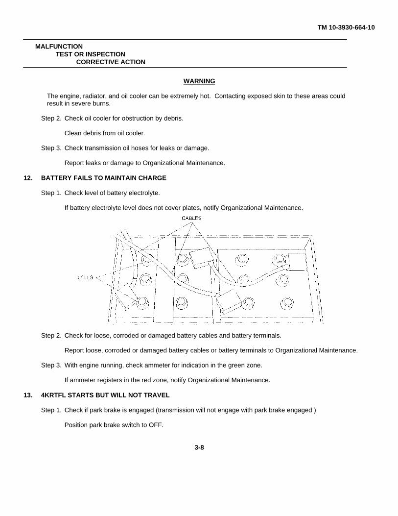
TM 10-3930-664-10
MALFUNCTIONTEST OR INSPECTION
CORRECTIVE ACTION
WARNING
The engine, radiator, and oil cooler can be extremely hot. Contacting exposed skin to these areas couldresult in severe burns.
Step 2. Check oil cooler for obstruction by debris.
Clean debris from oil cooler.
Step 3. Check transmission oil hoses for leaks or damage.
Report leaks or damage to Organizational Maintenance.
12. BATTERY FAILS TO MAINTAIN CHARGE
Step 1. Check level of battery electrolyte.
If battery electrolyte level does not cover plates, notify Organizational Maintenance.
Step 2. Check for loose, corroded or damaged battery cables and battery terminals.
Report loose, corroded or damaged battery cables or battery terminals to Organizational Maintenance.
Step 3. With engine running, check ammeter for indication in the green zone.
If ammeter registers in the red zone, notify Organizational Maintenance.
13. 4KRTFL STARTS BUT WILL NOT TRAVEL
Step 1. Check if park brake is engaged (transmission will not engage with park brake engaged )
Position park brake switch to OFF.
3-8
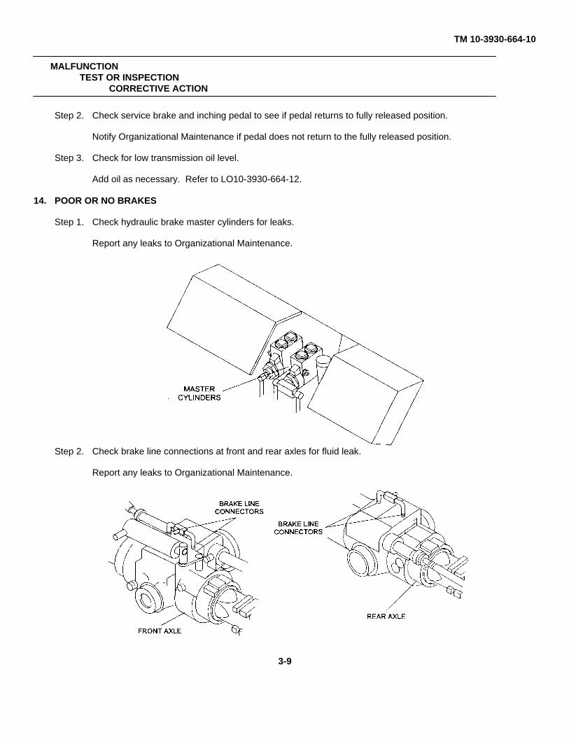
TM 10-3930-664-10
MALFUNCTIONTEST OR INSPECTION
CORRECTIVE ACTION
Step 2. Check service brake and inching pedal to see if pedal returns to fully released position.
Notify Organizational Maintenance if pedal does not return to the fully released position.
Step 3. Check for low transmission oil level.
Add oil as necessary. Refer to LO10-3930-664-12.
14. POOR OR NO BRAKES
Step 1. Check hydraulic brake master cylinders for leaks.
Report any leaks to Organizational Maintenance.
Step 2. Check brake line connections at front and rear axles for fluid leak.
Report any leaks to Organizational Maintenance.
3-9
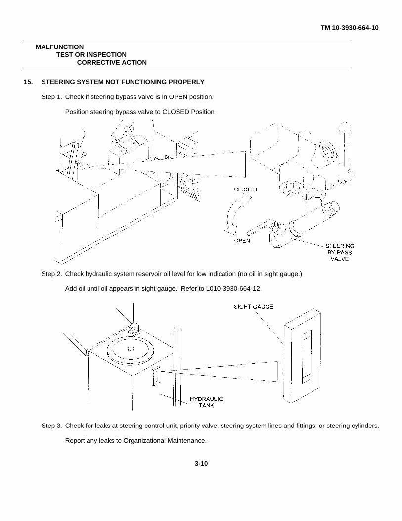
TM 10-3930-664-10
MALFUNCTIONTEST OR INSPECTION
CORRECTIVE ACTION
15. STEERING SYSTEM NOT FUNCTIONING PROPERLY
Step 1. Check if steering bypass valve is in OPEN position.
Position steering bypass valve to CLOSED Position
Step 2. Check hydraulic system reservoir oil level for low indication (no oil in sight gauge.)
Add oil until oil appears in sight gauge. Refer to L010-3930-664-12.
Step 3. Check for leaks at steering control unit, priority valve, steering system lines and fittings, or steering cylinders.
Report any leaks to Organizational Maintenance.
3-10
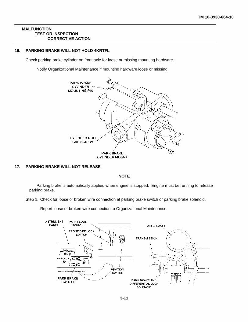
TM 10-3930-664-10
MALFUNCTIONTEST OR INSPECTION
CORRECTIVE ACTION
16. PARKING BRAKE WILL NOT HOLD 4KRTFL
Check parking brake cylinder on front axle for loose or missing mounting hardware.
Notify Organizational Maintenance if mounting hardware loose or missing.
17. PARKING BRAKE WILL NOT RELEASE
NOTE
Parking brake is automatically applied when engine is stopped. Engine must be running to releaseparking brake.
Step 1. Check for loose or broken wire connection at parking brake switch or parking brake solenoid.
Report loose or broken wire connection to Organizational Maintenance.
3-11
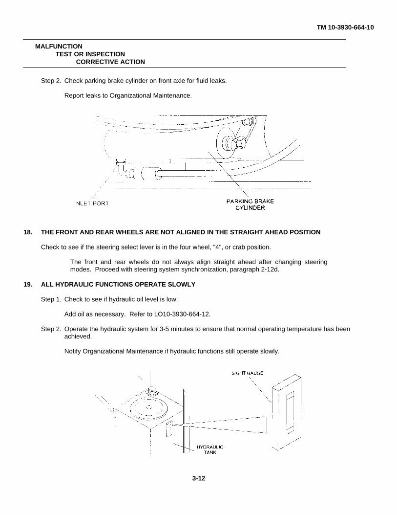
TM 10-3930-664-10
MALFUNCTIONTEST OR INSPECTION
CORRECTIVE ACTION
Step 2. Check parking brake cylinder on front axle for fluid leaks.
Report leaks to Organizational Maintenance.
18. THE FRONT AND REAR WHEELS ARE NOT ALIGNED IN THE STRAIGHT AHEAD POSITION
Check to see if the steering select lever is in the four wheel, "4", or crab position.
The front and rear wheels do not always align straight ahead after changing steeringmodes. Proceed with steering system synchronization, paragraph 2-12d.
19. ALL HYDRAULIC FUNCTIONS OPERATE SLOWLY
Step 1. Check to see if hydraulic oil level is low.
Add oil as necessary. Refer to LO10-3930-664-12.
Step 2. Operate the hydraulic system for 3-5 minutes to ensure that normal operating temperature has beenachieved.
Notify Organizational Maintenance if hydraulic functions still operate slowly.
3-12
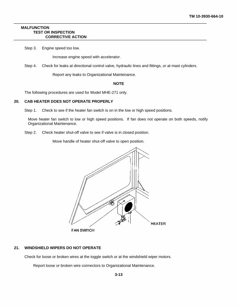
TM 10-3930-664-10
MALFUNCTIONTEST OR INSPECTION
CORRECTIVE ACTION
Step 3. Engine speed too low.
Increase engine speed with accelerator.
Step 4. Check for leaks at directional control valve, hydraulic lines and fittings, or at mast cylinders.
Report any leaks to Organizational Maintenance.
NOTE
The following procedures are used for Model MHE-271 only.
20. CAB HEATER DOES NOT OPERATE PROPERLY
Step 1. Check to see if the heater fan switch is on in the low or high speed positions.
Move heater fan switch to low or high speed positions. If fan does not operate on both speeds, notifyOrganizational Maintenance.
Step 2. Check heater shut-off valve to see if valve is in closed position.
Move handle of heater shut-off valve to open position.
21. WINDSHIELD WIPERS DO NOT OPERATE
Check for loose or broken wires at the toggle switch or at the windshield wiper motors.
Report loose or broken wire connectors to Organizational Maintenance.
3-13
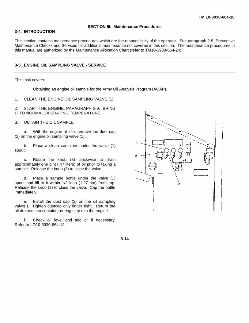
TM 10-3930-664-10
SECTION III. Maintenance Procedures3-4. INTRODUCTION
This section contains maintenance procedures which are the responsibility of the operator. See paragraph 2-5, PreventiveMaintenance Checks and Services for additional maintenance not covered in this section. The maintenance procedures inthis manual are authorized by the Maintenance Allocation Chart (refer to TM10-3930-664-24).
3-5. ENGINE OIL SAMPLING VALVE - SERVICE
This task covers:
Obtaining an engine oil sample for the Army Oil Analysis Program (AOAP).
1. CLEAN THE ENGINE OIL SAMPLING VALVE (1).
2. START THE ENGINE, PARAGRAPH 2-9. BRINGIT TO NORMAL OPERATING TEMPERATURE.
3. OBTAIN THE OIL SAMPLE.
a. With the engine at idle, remove the dust cap(2) on the engine oil sampling valve (1).
b. Place a clean container under the valve (1)spout.
c. Rotate the knob (3) clockwise to drainapproximately one pint (.47 liters) of oil prior to taking asample. Release the knob (3) to close the valve.
d. Place a sample bottle under the valve (1)spout and fill to it within 1/2 inch (1.27 cm) from top.Release the knob (3) to close the valve. Cap the bottleimmediately.
e. Install the dust cap (2) on the oil samplingvalve(I). Tighten dustcap only finger tight. Return theoil drained into container during step c to the engine.
f. Check oil level and add oil if necessary.Refer to LO10-3930-664-12.
3-14
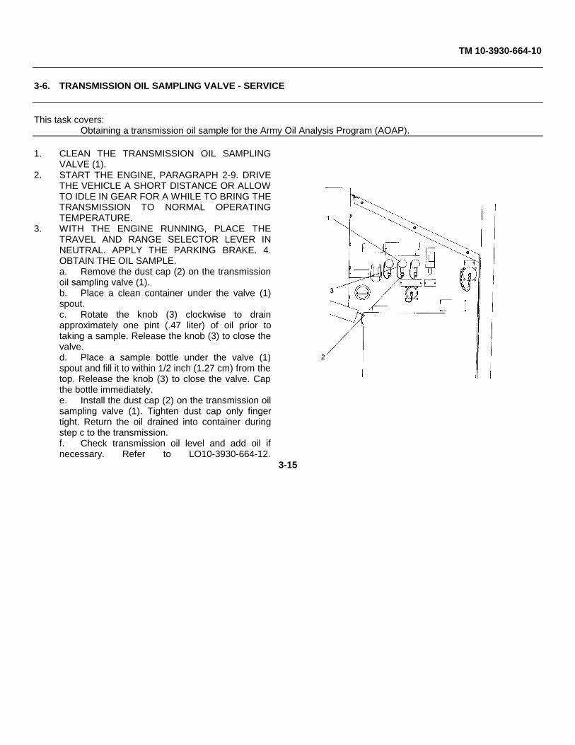
TM 10-3930-664-10
3-6. TRANSMISSION OIL SAMPLING VALVE - SERVICE
This task covers:Obtaining a transmission oil sample for the Army Oil Analysis Program (AOAP).
1. CLEAN THE TRANSMISSION OIL SAMPLINGVALVE (1).
2. START THE ENGINE, PARAGRAPH 2-9. DRIVETHE VEHICLE A SHORT DISTANCE OR ALLOWTO IDLE IN GEAR FOR A WHILE TO BRING THETRANSMISSION TO NORMAL OPERATINGTEMPERATURE.
3. WITH THE ENGINE RUNNING, PLACE THETRAVEL AND RANGE SELECTOR LEVER INNEUTRAL. APPLY THE PARKING BRAKE. 4.OBTAIN THE OIL SAMPLE.a. Remove the dust cap (2) on the transmissionoil sampling valve (1).b. Place a clean container under the valve (1)spout.c. Rotate the knob (3) clockwise to drainapproximately one pint (.47 liter) of oil prior totaking a sample. Release the knob (3) to close thevalve.d. Place a sample bottle under the valve (1)spout and fill it to within 1/2 inch (1.27 cm) from thetop. Release the knob (3) to close the valve. Capthe bottle immediately.e. Install the dust cap (2) on the transmission oilsampling valve (1). Tighten dust cap only fingertight. Return the oil drained into container duringstep c to the transmission.f. Check transmission oil level and add oil ifnecessary. Refer to LO10-3930-664-12.
3-15
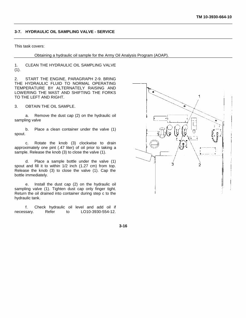
TM 10-3930-664-10
3-7. HYDRAULIC OIL SAMPLING VALVE - SERVICE
This task covers:
Obtaining a hydraulic oil sample for the Army Oil Analysis Program (AOAP).
1. CLEAN THE HYDRAULIC OIL SAMPLING VALVE(1).
2. START THE ENGINE, PARAGRAPH 2-9. BRINGTHE HYDRAULIC FLUID TO NORMAL OPERATINGTEMPERATURE BY ALTERNATELY RAISING ANDLOWERING THE MAST AND SHIFTING THE FORKSTO THE LEFT AND RIGHT.
3. OBTAIN THE OIL SAMPLE.
a. Remove the dust cap (2) on the hydraulic oilsampling valve
b. Place a clean container under the valve (1)spout.
c. Rotate the knob (3) clockwise to drainapproximately one pint (.47 liter) of oil prior to taking asample. Release the knob (3) to close the valve (1).
d. Place a sample bottle under the valve (1)spout and fill it to within 1/2 inch (1.27 cm) from top.Release the knob (3) to close the valve (1). Cap thebottle immediately.
e. Install the dust cap (2) on the hydraulic oilsampling valve (1). Tighten dust cap only finger tight.Return the oil drained into container during step c to thehydraulic tank.
f. Check hydraulic oil level and add oil ifnecessary. Refer to LO10-3930-554-12.
3-16
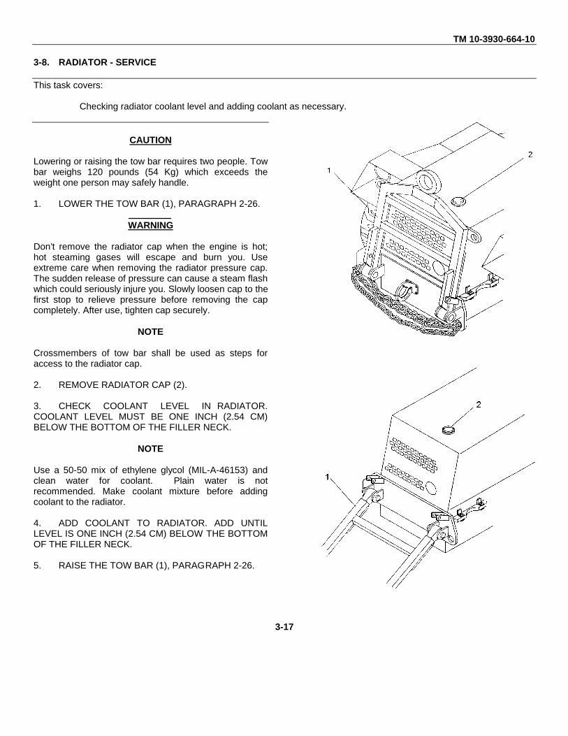
TM 10-3930-664-10
3-8. RADIATOR - SERVICE
This task covers:
Checking radiator coolant level and adding coolant as necessary.
CAUTION
Lowering or raising the tow bar requires two people. Towbar weighs 120 pounds (54 Kg) which exceeds theweight one person may safely handle.
1. LOWER THE TOW BAR (1), PARAGRAPH 2-26.
WARNING
Don’t remove the radiator cap when the engine is hot;hot steaming gases will escape and burn you. Useextreme care when removing the radiator pressure cap.The sudden release of pressure can cause a steam flashwhich could seriously injure you. Slowly loosen cap to thefirst stop to relieve pressure before removing the capcompletely. After use, tighten cap securely.
NOTE
Crossmembers of tow bar shall be used as steps foraccess to the radiator cap.
2. REMOVE RADIATOR CAP (2).
3. CHECK COOLANT LEVEL IN RADIATOR.COOLANT LEVEL MUST BE ONE INCH (2.54 CM)BELOW THE BOTTOM OF THE FILLER NECK.
NOTE
Use a 50-50 mix of ethylene glycol (MIL-A-46153) andclean water for coolant. Plain water is notrecommended. Make coolant mixture before addingcoolant to the radiator.
4. ADD COOLANT TO RADIATOR. ADD UNTILLEVEL IS ONE INCH (2.54 CM) BELOW THE BOTTOMOF THE FILLER NECK.
5. RAISE THE TOW BAR (1), PARAGRAPH 2-26.
3-17
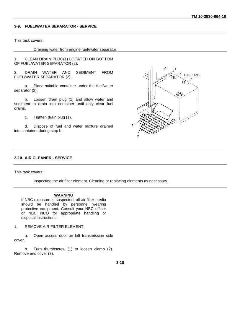
TM 10-3930-664-10
3-9. FUEL/WATER SEPARATOR - SERVICE
This task covers:
Draining water from engine fuel/water separator.
1. CLEAN DRAIN PLUG(1) LOCATED ON BOTTOMOF FUEL/WATER SEPARATOR (2).
2. DRAIN WATER AND SEDIMENT FROMFUEL/WATER SEPARATOR (2).
a. Place suitable container under the fuel/waterseparator (2).
b. Loosen drain plug (1) and allow water andsediment to drain into container until only clear fueldrains.
c. Tighten drain plug (1).
d. Dispose of fuel and water mixture drainedinto container during step b.
3-10. AIR CLEANER - SERVICE
This task covers:
Inspecting the air filter element. Cleaning or replacing elements as necessary.
WARNINGIf NBC exposure is suspected, all air filter mediashould be handled by personnel wearingprotective equipment. Consult your NBC officeror NBC NCO for appropriate handling ordisposal instructions.
1. REMOVE AIR FILTER ELEMENT.
a. Open access door on left transmission sidecover.
b. Turn thumbscrew (1) to loosen clamp (2).Remove end cover (3).
3-18
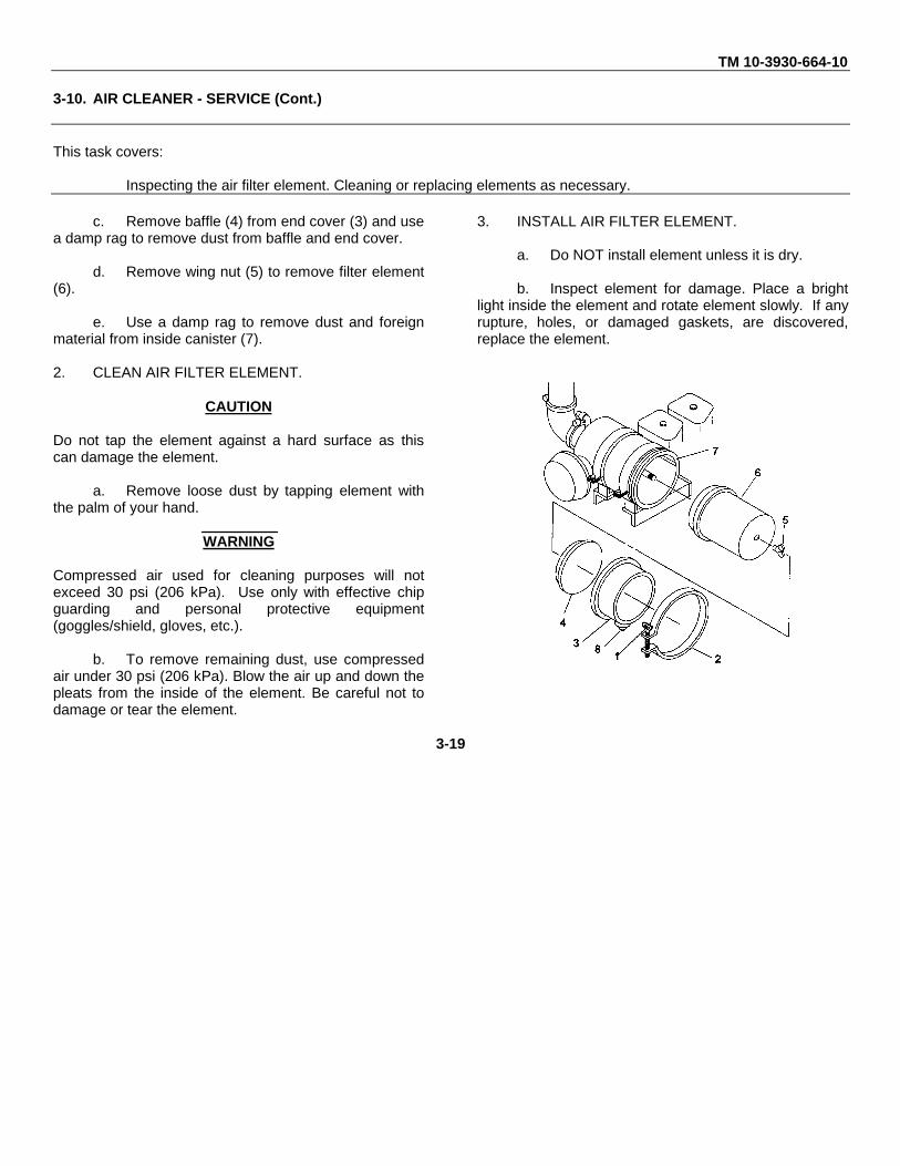
TM 10-3930-664-10
3-10. AIR CLEANER - SERVICE (Cont.)
This task covers:
Inspecting the air filter element. Cleaning or replacing elements as necessary.
c. Remove baffle (4) from end cover (3) and usea damp rag to remove dust from baffle and end cover.
d. Remove wing nut (5) to remove filter element(6).
e. Use a damp rag to remove dust and foreignmaterial from inside canister (7).
2. CLEAN AIR FILTER ELEMENT.
CAUTION
Do not tap the element against a hard surface as thiscan damage the element.
a. Remove loose dust by tapping element withthe palm of your hand.
WARNING
Compressed air used for cleaning purposes will notexceed 30 psi (206 kPa). Use only with effective chipguarding and personal protective equipment(goggles/shield, gloves, etc.).
b. To remove remaining dust, use compressedair under 30 psi (206 kPa). Blow the air up and down thepleats from the inside of the element. Be careful not todamage or tear the element.
3. INSTALL AIR FILTER ELEMENT.
a. Do NOT install element unless it is dry.
b. Inspect element for damage. Place a brightlight inside the element and rotate element slowly. If anyrupture, holes, or damaged gaskets, are discovered,replace the element.
3-19
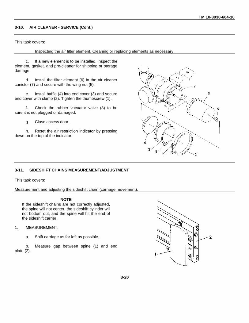
TM 10-3930-664-10
3-10. AIR CLEANER - SERVICE (Cont.)
This task covers:
Inspecting the air filter element. Cleaning or replacing elements as necessary.
c. If a new element is to be installed, inspect theelement, gasket, and pre-cleaner for shipping or storagedamage.
d. Install the filter element (6) in the air cleanercanister (7) and secure with the wing nut (5).
e. Install baffle (4) into end cover (3) and secureend cover with clamp (2). Tighten the thumbscrew (1).
f. Check the rubber vacuator valve (8) to besure it is not plugged or damaged.
g. Close access door.
h. Reset the air restriction indicator by pressingdown on the top of the indicator.
3-11. SIDESHIFT CHAINS MEASUREMENT/ADJUSTMENT
This task covers:
Measurement and adjusting the sideshift chain (carriage movement).
NOTEIf the sideshift chains are not correctly adjusted,the spine will not center, the sideshift cylinder willnot bottom out, and the spine will hit the end ofthe sideshift carrier.
1. MEASUREMENT.
a. Shift carriage as far left as possible.
b. Measure gap between spine (1) and endplate (2).
3-20
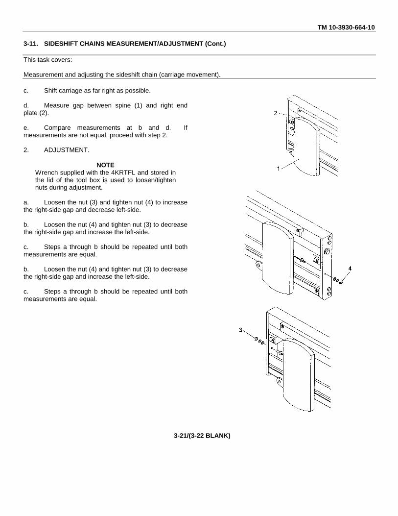
TM 10-3930-664-10
3-11. SIDESHIFT CHAINS MEASUREMENT/ADJUSTMENT (Cont.)
This task covers:
Measurement and adjusting the sideshift chain (carriage movement).
c. Shift carriage as far right as possible.
d. Measure gap between spine (1) and right endplate (2).
e. Compare measurements at b and d. Ifmeasurements are not equal, proceed with step 2.
2. ADJUSTMENT.
NOTEWrench supplied with the 4KRTFL and stored inthe lid of the tool box is used to loosen/tightennuts during adjustment.
a. Loosen the nut (3) and tighten nut (4) to increasethe right-side gap and decrease left-side.
b. Loosen the nut (4) and tighten nut (3) to decreasethe right-side gap and increase the left-side.
c. Steps a through b should be repeated until bothmeasurements are equal.
b. Loosen the nut (4) and tighten nut (3) to decreasethe right-side gap and increase the left-side.
c. Steps a through b should be repeated until bothmeasurements are equal.
3-21/(3-22 BLANK)
TM 10-3930-664-10
APPENDIX A
REFERENCES
A-1. FORMSThe following forms pertain to this material. (Refer to DA Pamphlet 310-2 for index of blank forms.)
Standard Form 46, U.S. Government Motor Vehicle Operator’s Identification Card
Standard Form 91, Operator’s Report of Motor Vehicle Accident.
Recommended Changes to DA Publications and Blank Form, DA Form 2028.
DA PAM 738-750, The Army Maintenance Management System (TAMMS), for instructions on the use of maintenanceforms pertaining to this material.
A-2. OTHER PUBLICATIONS
The following publications contain information pertinent to the major item materiel and associated equipment.
The Army Maintenance Management System (TAMMS) applies as follows:
(1) Army Equipment Log Book Binder, NSN 7510-00-889-3494.
(2) Case, Maintenance and Operational Manuals, NSN 7520-00-559-5618.
(3) DA Form 2407, Maintenance Request.
(4) DA Form 2408, Equipment Log Book Assembly (Record).
(5) DA Form 2408-1, Equipment Daily and Monthly Log.
(6) DA Form 2408-5, Equipment Modification Record.
(7) DA Form 2408-9, Equipment Control Record.
(8) DA Form 2409, Equipment Maintenance Log (Consolidated).
A-1
a. Operating Vehicle
Driver Selection and Training (Wheeled Vehicles) FM 55-30Manual for the Wheeled Vehicle Driver FM 21-305Prevention of Motor Vehicle Accidents AR 385-55Accident Reporting and Records AR 385-40
b. Maintenance and Repair
The Army, Maintenance management Systems (TAMMS) DA PA-M 738-750Identification List for Fuels, Lubricants. Oils and Waxes C 9190-ILDescription. Use. Bonding Techniques. and Properties of Adhesives TB ORD 1032Materiels Used for Cleaning. Preserving. Abrading. and CementingOrdinance Material and Related Materials, Including Chemicals TM 9-247Metal Body Repair and Related Operations FM 43-2Welding Theory and Application TM 9-247Painting Instructions for Field Use TM 43-0139Inspection. Care. and Maintenance of Anti-Friction Bearings TM 9-214Operator’s. Organizational. Direct Support and General Mainten-ance Manual for Lead-Acid Storage Batteries. 4HN, 24 (NSN 6140-00-059-3528) MS 75047-1. 2HN, 12V (NSN 6140-00-057-2554);MS 35000-3. TM 9-6140-200-14
c. Cold Operation and Maintenance
Basic Cold Weather Manual FMI 31-70Northern Operations FFM 31-71Operation and Maintenance of Ordnance Materiel in ExtremeCold Weather (0°F to -65°F) FM 9-207Winterization Kits for Army, Tank-Automotive Materiel SB 9-16
d. Decontamination
Chemical, Biological, and Radiological (CBR) Decontamination TM 3-220Chemical, Biological, Radiological, and Nuclear Defense (NBC) FM 21-40
e. General
Hand Portable Fire Extinguishers Approved for Army users TB 5-4200-200-10Camouflage FM 5-20Procedures for Destruction of Equipment to Prevent Enemy users(Mobility Equipment Command) TM 750-244-3Administrative Storage of Equipment TM 740-90-1Preservation of USAMECOM Mechanical Equipment for Shipmentand Storage TM 740-97-2
A-2
TM 10-3930-664-10
APPENDIX B
COMPONENTS OF END ITEM (COEI) AND BASIC ISSUE ITEMS (BII) LISTS
SECTION I. Introduction
B-1. SCOPE
This appendix lists components of the end item and basic issue items for the 4KRTFL to help you inventory the items forsafe and efficient operation of the equipment.
B-2. GENERAL
The Components of End Item (COEI) and Basic Issue Items (BII) Lists is divided into the following sections:
a. Section II, Components of End Item. This listing is for information purposes only, and is not authority torequisition replacements. These items are part of the 4KRTFL, that are to be removed and separately packaged fortransportation or shipment. As part of the end item, these items must be with the end item whenever it is issued ortransferred between property accounts. Illustrations are furnished to help you find and identify the items.
b. Section III, Basic Issue Items. These essential items are required to place the 4KRTFL in operation, operate it,and to do emergency repairs. BII must be with the 4KRTFL during operation and when it is transferred between propertyaccounts. Listing these items is your authority to request/requisition them for replacement based on authorization of theend item by the TOE/MTOE. Illustrations are furnished to help you find and identify the items.
B-3. EXPLANATION OF COLUMNS
a. Column (1), Illus Number, gives you the number of the item illustrated.
b. Column (2), National Stock Number, identifies the stock number of the item to be used for requisitioningpurposes.
c. Column (3), Description and Usable On Code, identifies the Federal item name (in all capital letters) followed bya minimum description when needed. The last line below the description is the CAGEC (Commercial and GovernmentEntity Code) (in parenthesis) and the part number. If the item you need is not the same for different models of theequipment, a Usable On Code will appear on the right side Of the description column on the same line as the part number.These codes are identified below:
CODE USED ON
JPL Model MHE-270MRF Model MHE-271
d. Column (4), U/I (unit of issue), indicates how the item is issued for the National Stock Number shown in column two.
e. Column (5), Qty Rqd, indicates the quantity required.
B-1
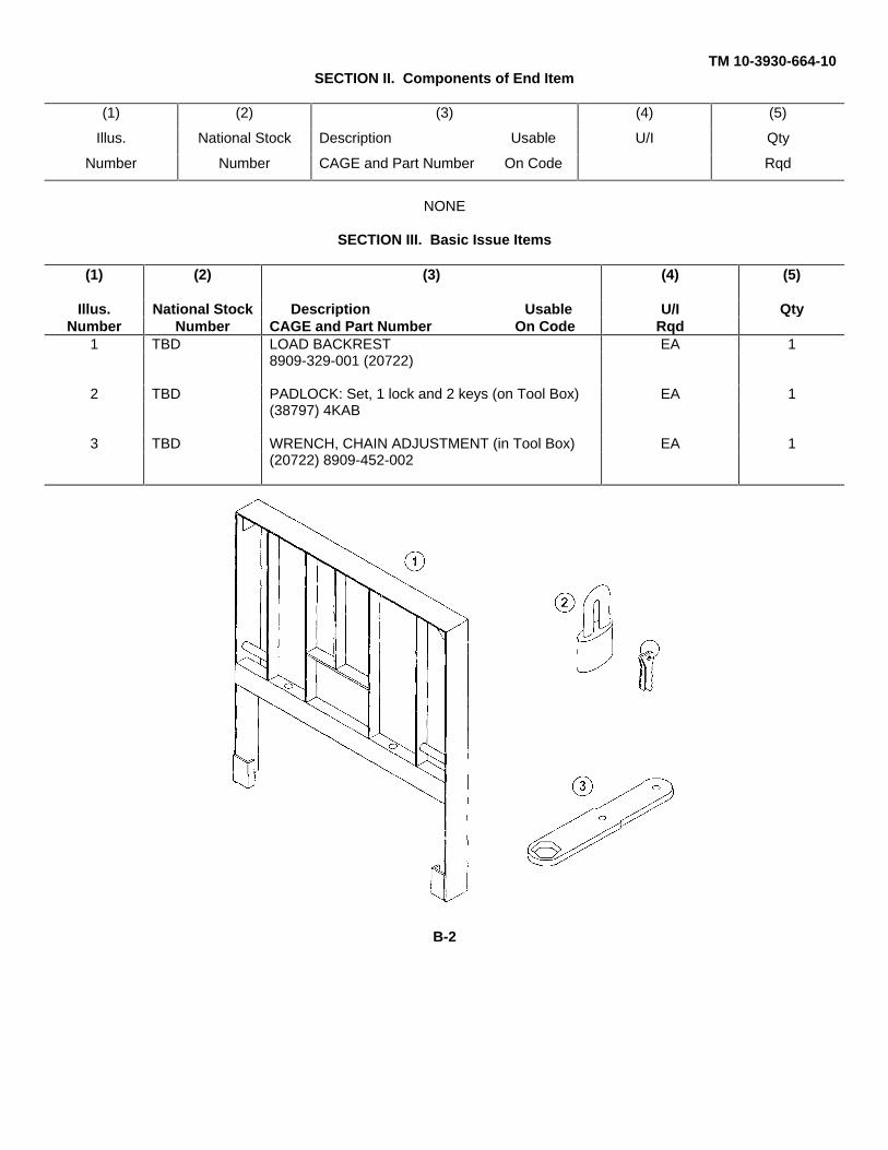
TM 10-3930-664-10SECTION II. Components of End Item
(1) (2) (3) (4) (5)
Illus. National Stock Description Usable U/I Qty
Number Number CAGE and Part Number On Code Rqd
NONE
SECTION III. Basic Issue Items
(1) (2) (3) (4) (5)
Illus. National Stock Description Usable U/I QtyNumber Number CAGE and Part Number On Code Rqd
1 TBD LOAD BACKREST EA 18909-329-001 (20722)
2 TBD PADLOCK: Set, 1 lock and 2 keys (on Tool Box) EA 1(38797) 4KAB
3 TBD WRENCH, CHAIN ADJUSTMENT (in Tool Box) EA 1(20722) 8909-452-002
B-2
TM 10-3039-664-10
APPENDIX C
ADDITIONAL AUTHORIZATION LIST
SECTION I. INTRODUCTION
C-1. SCOPE
This appendix lists additional items you are authorized for the support of the 4KRTFL.
C-2. GENERAL
This list identifies items that do not have to accompany the 4KRTFL and do not have to be turned in with it. These itemsare all authorized to you by CTA, MTOE, TDA, or JTA.
C-3. EXPLANATION OF LISTING
National stock numbers, descriptions, and recommended quantities are provided to help you identify and request theadditional items you require to support this equipment. The items are listed in alphabetical sequence by item name. If theitem you require differs between serial numbers of the same model, effective serial numbers are shown in the last line ofthe description. If item required differs for different models of this equipment, the model is shown under the "Usable onCode" heading in the description column. These codes are identified as:
CODE USED ON
JPL Model MHE-270MRF Model MHE-271
SECTION II. ADDITIONAL AUTHORIZATION LIST
(1) (2) (3) (4)National Stock Description Usable U/I Qty
Number CAGE and Part Number On Code Recm
NONE
C-1/(C-2 blank)
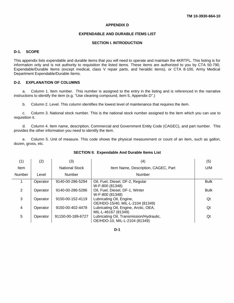
TM 10-3930-664-10
APPENDIX D
EXPENDABLE AND DURABLE ITEMS LIST
SECTION I. INTRODUCTION
D-1. SCOPE
This appendix lists expendable and durable items that you will need to operate and maintain the 4KRTFL. This listing is forinformation only and is not authority to requisition the listed items. These items are authorized to you by CTA 50-790,Expendable/Durable Items (except medical, class V repair parts, and heraldic items), or CTA 8-100, Army MedicalDepartment Expendable/Durable Items.
D-2. EXPLANATION OF COLUMNS
a. Column 1. Item number. This number is assigned to the entry in the listing and is referenced in the narrativeinstructions to identify the item (e.g. "Use cleaning compound, item 5, Appendix D".)
b. Column 2. Level. This column identifies the lowest level of maintenance that requires the item.
c. Column 3. National stock number. This is the national stock number assigned to the item which you can use torequisition it.
d. Column 4. Item name, description, Commercial and Government Entity Code (CAGEC), and part number. Thisprovides the other information you need to identify the item.
e. Column 5. Unit of measure. This code shows the physical measurement or count of an item, such as gallon,dozen, gross, etc.
SECTION II. Expendable And Durable Items List
(1) (2) (3) (4) (5)
Item National Stock Item Name, Description, CAGEC, Part U/M
Number Level Number Number
1 Operator 9140-00-286-5294 Oil, Fuel, Diesel, DF-2, Regular BulkW-F-800 (81348)
2 Operator 9140-00-286-5286 Oil, Fuel, Diesel, DF-1, Winter BulkW-F-800 (81348)
3 Operator 9150-00-152-4119 Lubricating Oil, Engine, QtOE/HDO-15/40, MIL-L-2104 (81349)
4 Operator 9150-00-402-4478 Lubricating Oil, Engine, Arctic, OEA, QtMIL-L-46167 (81349)
5 Operator 91150-00-189-6727 Lubricating Oil, Transmission/Hydraulic, QtOE/HDO-10, MIL-L-2104 (81349)
D-1
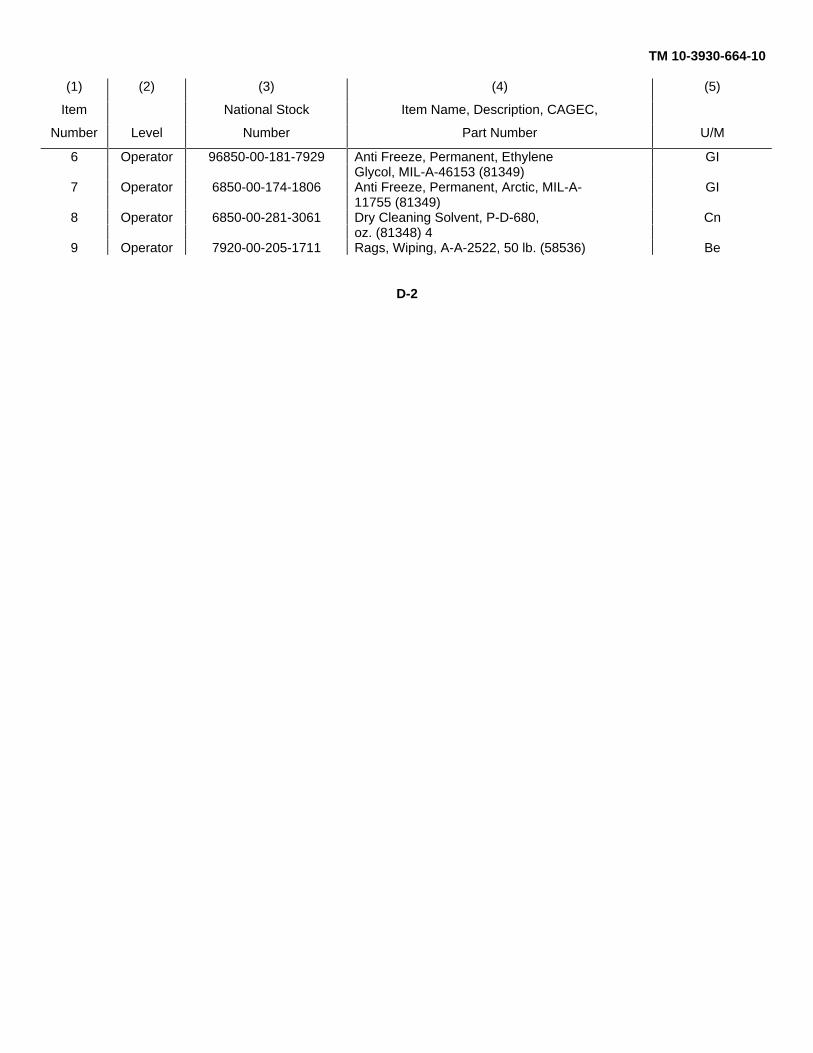
TM 10-3930-664-10
(1) (2) (3) (4) (5)
Item National Stock Item Name, Description, CAGEC,
Number Level Number Part Number U/M
6 Operator 96850-00-181-7929 Anti Freeze, Permanent, Ethylene GIGlycol, MIL-A-46153 (81349)
7 Operator 6850-00-174-1806 Anti Freeze, Permanent, Arctic, MIL-A- GI11755 (81349)
8 Operator 6850-00-281-3061 Dry Cleaning Solvent, P-D-680, Cnoz. (81348) 4
9 Operator 7920-00-205-1711 Rags, Wiping, A-A-2522, 50 lb. (58536) Be
D-2
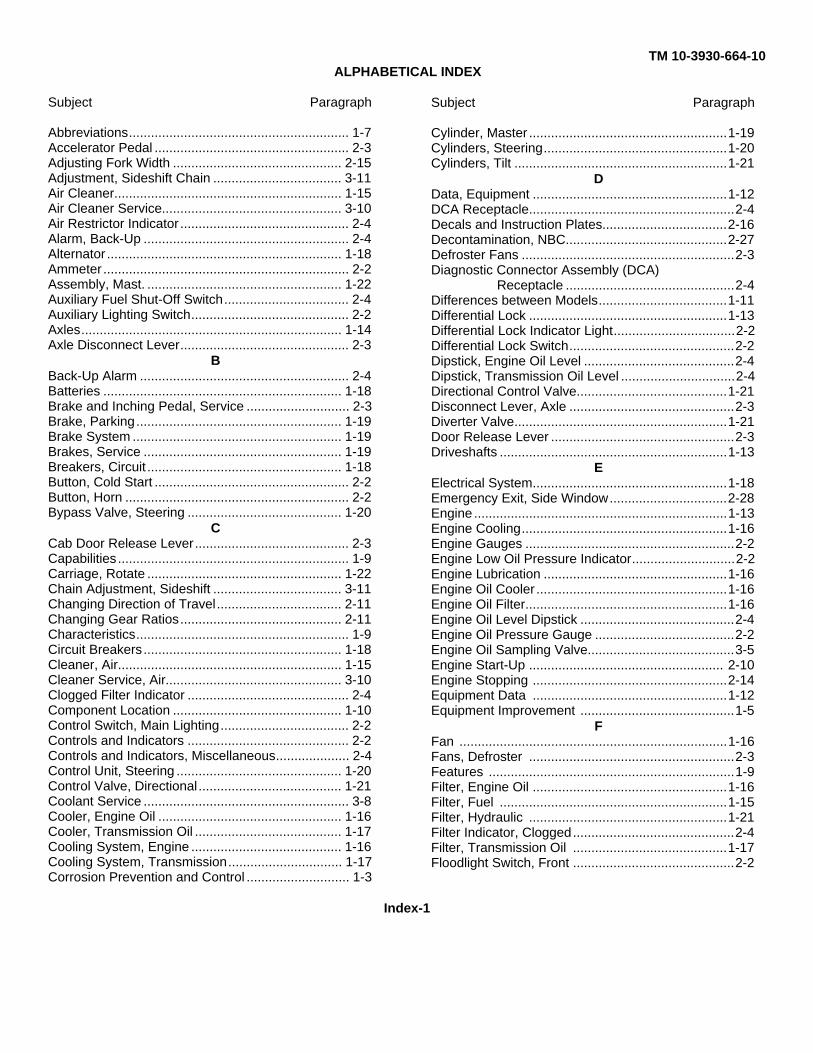
TM 10-3930-664-10ALPHABETICAL INDEX
Subject Paragraph
Abbreviations............................................................ 1-7Accelerator Pedal ..................................................... 2-3Adjusting Fork Width .............................................. 2-15Adjustment, Sideshift Chain ................................... 3-11Air Cleaner.............................................................. 1-15Air Cleaner Service................................................. 3-10Air Restrictor Indicator .............................................. 2-4Alarm, Back-Up ........................................................ 2-4Alternator ................................................................ 1-18Ammeter ................................................................... 2-2Assembly, Mast. ..................................................... 1-22Auxiliary Fuel Shut-Off Switch.................................. 2-4Auxiliary Lighting Switch........................................... 2-2Axles....................................................................... 1-14Axle Disconnect Lever.............................................. 2-3
BBack-Up Alarm ......................................................... 2-4Batteries ................................................................. 1-18Brake and Inching Pedal, Service ............................ 2-3Brake, Parking........................................................ 1-19Brake System ......................................................... 1-19Brakes, Service ...................................................... 1-19Breakers, Circuit ..................................................... 1-18Button, Cold Start ..................................................... 2-2Button, Horn ............................................................. 2-2Bypass Valve, Steering .......................................... 1-20
CCab Door Release Lever.......................................... 2-3Capabilities ............................................................... 1-9Carriage, Rotate ..................................................... 1-22Chain Adjustment, Sideshift ................................... 3-11Changing Direction of Travel.................................. 2-11Changing Gear Ratios............................................ 2-11Characteristics.......................................................... 1-9Circuit Breakers...................................................... 1-18Cleaner, Air............................................................. 1-15Cleaner Service, Air................................................ 3-10Clogged Filter Indicator ............................................ 2-4Component Location .............................................. 1-10Control Switch, Main Lighting................................... 2-2Controls and Indicators ............................................ 2-2Controls and Indicators, Miscellaneous.................... 2-4Control Unit, Steering ............................................. 1-20Control Valve, Directional....................................... 1-21Coolant Service ........................................................ 3-8Cooler, Engine Oil .................................................. 1-16Cooler, Transmission Oil ........................................ 1-17Cooling System, Engine ......................................... 1-16Cooling System, Transmission............................... 1-17Corrosion Prevention and Control ............................ 1-3
Subject Paragraph
Cylinder, Master ......................................................1-19Cylinders, Steering..................................................1-20Cylinders, Tilt ..........................................................1-21
DData, Equipment .....................................................1-12DCA Receptacle........................................................2-4Decals and Instruction Plates..................................2-16Decontamination, NBC............................................2-27Defroster Fans ..........................................................2-3Diagnostic Connector Assembly (DCA)
Receptacle ..............................................2-4Differences between Models...................................1-11Differential Lock ......................................................1-13Differential Lock Indicator Light.................................2-2Differential Lock Switch.............................................2-2Dipstick, Engine Oil Level .........................................2-4Dipstick, Transmission Oil Level ...............................2-4Directional Control Valve.........................................1-21Disconnect Lever, Axle .............................................2-3Diverter Valve..........................................................1-21Door Release Lever ..................................................2-3Driveshafts ..............................................................1-13
EElectrical System.....................................................1-18Emergency Exit, Side Window................................2-28Engine .....................................................................1-13Engine Cooling........................................................1-16Engine Gauges .........................................................2-2Engine Low Oil Pressure Indicator............................2-2Engine Lubrication ..................................................1-16Engine Oil Cooler ....................................................1-16Engine Oil Filter.......................................................1-16Engine Oil Level Dipstick ..........................................2-4Engine Oil Pressure Gauge ......................................2-2Engine Oil Sampling Valve........................................3-5Engine Start-Up ..................................................... 2-10Engine Stopping .....................................................2-14Equipment Data .....................................................1-12Equipment Improvement ..........................................1-5
FFan .........................................................................1-16Fans, Defroster ........................................................2-3Features ...................................................................1-9Filter, Engine Oil .....................................................1-16Filter, Fuel ..............................................................1-15Filter, Hydraulic ......................................................1-21Filter Indicator, Clogged............................................2-4Filter, Transmission Oil ..........................................1-17Floodlight Switch, Front ............................................2-2
Index-1
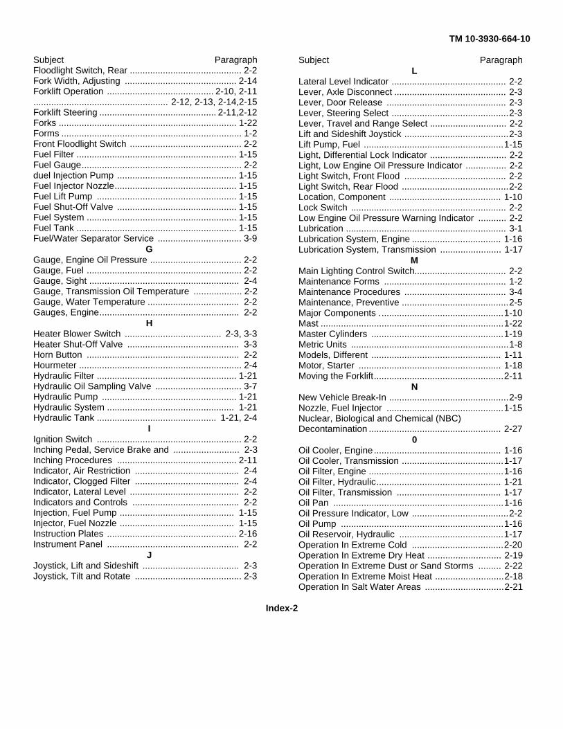
TM 10-3930-664-10
Subject ParagraphFloodlight Switch, Rear ............................................ 2-2Fork Width, Adjusting ............................................ 2-14Forklift Operation .......................................... 2-10, 2-11..................................................... 2-12, 2-13, 2-14,2-15Forklift Steering .............................................. 2-11,2-12Forks ...................................................................... 1-22Forms ....................................................................... 1-2Front Floodlight Switch ............................................ 2-2Fuel Filter ............................................................... 1-15Fuel Gauge............................................................... 2-2duel Injection Pump ............................................... 1-15Fuel Injector Nozzle................................................ 1-15Fuel Lift Pump ....................................................... 1-15Fuel Shut-Off Valve ............................................... 1-15Fuel System ........................................................... 1-15Fuel Tank ............................................................... 1-15Fuel/Water Separator Service ................................. 3-9
GGauge, Engine Oil Pressure .................................... 2-2Gauge, Fuel ............................................................. 2-2Gauge, Sight ........................................................... 2-4Gauge, Transmission Oil Temperature ................... 2-2Gauge, Water Temperature .................................... 2-2Gauges, Engine....................................................... 2-2
HHeater Blower Switch ...................................... 2-3, 3-3Heater Shut-Off Valve ............................................ 3-3Horn Button ............................................................ 2-2Hourmeter ................................................................ 2-4Hydraulic Filter ....................................................... 1-21Hydraulic Oil Sampling Valve .................................. 3-7Hydraulic Pump ..................................................... 1-21Hydraulic System .................................................. 1-21Hydraulic Tank ............................................... 1-21, 2-4
IIgnition Switch ......................................................... 2-2Inching Pedal, Service Brake and .......................... 2-3Inching Procedures ............................................... 2-11Indicator, Air Restriction ......................................... 2-4Indicator, Clogged Filter ......................................... 2-4Indicator, Lateral Level ........................................... 2-2Indicators and Controls .......................................... 2-2Injection, Fuel Pump ............................................. 1-15Injector, Fuel Nozzle ............................................. 1-15Instruction Plates ................................................... 2-16Instrument Panel .................................................... 2-2
JJoystick, Lift and Sideshift ...................................... 2-3Joystick, Tilt and Rotate .......................................... 2-3
Subject ParagraphL
Lateral Level Indicator ............................................. 2-2Lever, Axle Disconnect ............................................ 2-3Lever, Door Release ............................................... 2-3Lever, Steering Select ..............................................2-3Lever, Travel and Range Select .............................. 2-2Lift and Sideshift Joystick .........................................2-3Lift Pump, Fuel .......................................................1-15Light, Differential Lock Indicator .............................. 2-2Light, Low Engine Oil Pressure Indicator ................ 2-2Light Switch, Front Flood ........................................ 2-2Light Switch, Rear Flood ..........................................2-2Location, Component ............................................ 1-10Lock Switch ............................................................. 2-2Low Engine Oil Pressure Warning Indicator ........... 2-2Lubrication ............................................................... 3-1Lubrication System, Engine ................................... 1-16Lubrication System, Transmission ........................ 1-17
MMain Lighting Control Switch.................................... 2-2Maintenance Forms ................................................ 1-2Maintenance Procedures ........................................ 3-4Maintenance, Preventive ..........................................2-5Major Components .................................................1-10Mast ........................................................................1-22Master Cylinders ....................................................1-19Metric Units ..............................................................1-8Models, Different ................................................... 1-11Motor, Starter ........................................................ 1-18Moving the Forklift...................................................2-11
NNew Vehicle Break-In ...............................................2-9Nozzle, Fuel Injector ..............................................1-15Nuclear, Biological and Chemical (NBC)Decontamination .................................................... 2-27
0Oil Cooler, Engine.................................................. 1-16Oil Cooler, Transmission ........................................1-17Oil Filter, Engine .....................................................1-16Oil Filter, Hydraulic................................................. 1-21Oil Filter, Transmission ......................................... 1-17Oil Pan ...................................................................1-16Oil Pressure Indicator, Low ......................................2-2Oil Pump ................................................................1-16Oil Reservoir, Hydraulic .........................................1-17Operation In Extreme Cold ....................................2-20Operation In Extreme Dry Heat ............................. 2-19Operation In Extreme Dust or Sand Storms ......... 2-22Operation In Extreme Moist Heat ...........................2-18Operation In Salt Water Areas ...............................2-21
Index-2
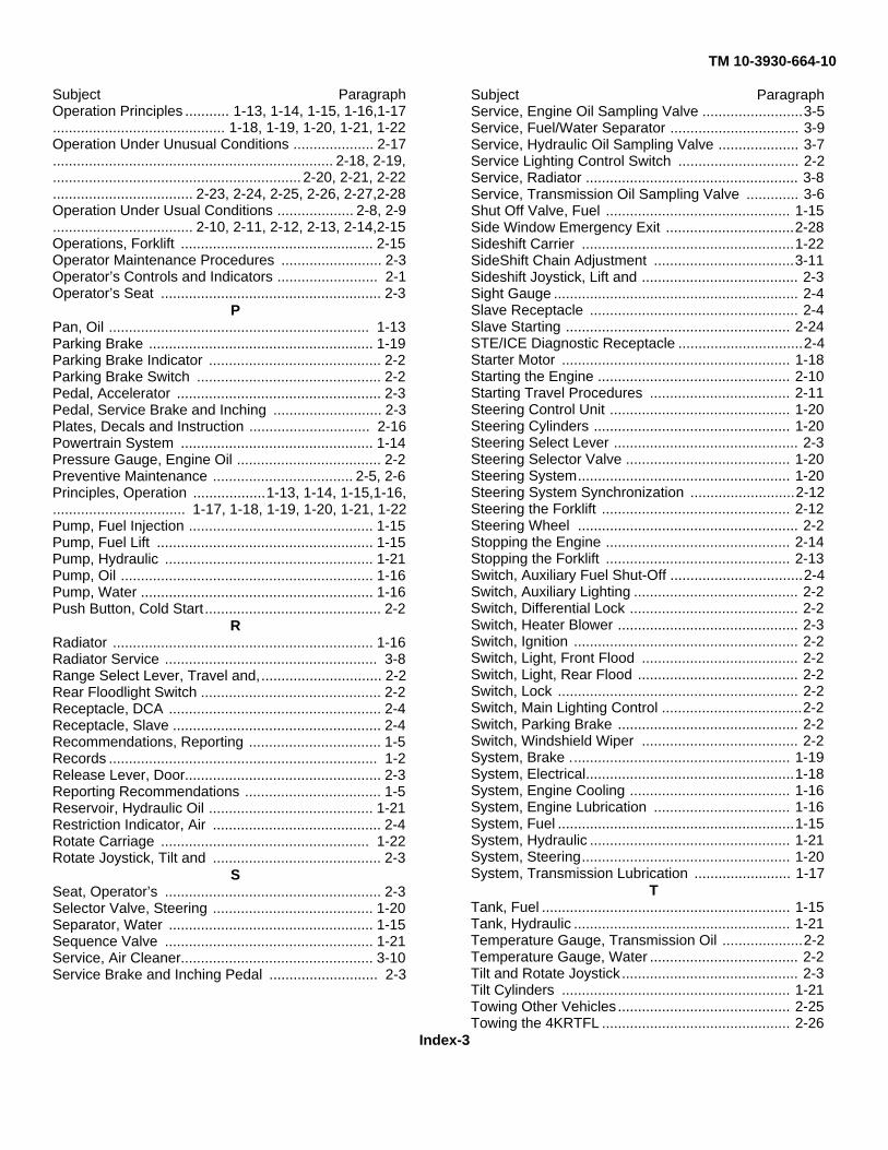
TM 10-3930-664-10
Subject ParagraphOperation Principles ........... 1-13, 1-14, 1-15, 1-16,1-17........................................... 1-18, 1-19, 1-20, 1-21, 1-22Operation Under Unusual Conditions .................... 2-17...................................................................... 2-18, 2-19,.............................................................. 2-20, 2-21, 2-22................................... 2-23, 2-24, 2-25, 2-26, 2-27,2-28Operation Under Usual Conditions ................... 2-8, 2-9................................... 2-10, 2-11, 2-12, 2-13, 2-14,2-15Operations, Forklift ................................................ 2-15Operator Maintenance Procedures ......................... 2-3Operator’s Controls and Indicators ......................... 2-1Operator’s Seat ....................................................... 2-3
PPan, Oil ................................................................. 1-13Parking Brake ........................................................ 1-19Parking Brake Indicator ........................................... 2-2Parking Brake Switch .............................................. 2-2Pedal, Accelerator ................................................... 2-3Pedal, Service Brake and Inching ........................... 2-3Plates, Decals and Instruction .............................. 2-16Powertrain System ................................................ 1-14Pressure Gauge, Engine Oil .................................... 2-2Preventive Maintenance ................................... 2-5, 2-6Principles, Operation ..................1-13, 1-14, 1-15,1-16,................................. 1-17, 1-18, 1-19, 1-20, 1-21, 1-22Pump, Fuel Injection .............................................. 1-15Pump, Fuel Lift ...................................................... 1-15Pump, Hydraulic .................................................... 1-21Pump, Oil ............................................................... 1-16Pump, Water .......................................................... 1-16Push Button, Cold Start ............................................ 2-2
RRadiator ................................................................. 1-16Radiator Service ..................................................... 3-8Range Select Lever, Travel and,.............................. 2-2Rear Floodlight Switch ............................................. 2-2Receptacle, DCA ..................................................... 2-4Receptacle, Slave .................................................... 2-4Recommendations, Reporting ................................. 1-5Records ................................................................... 1-2Release Lever, Door................................................. 2-3Reporting Recommendations .................................. 1-5Reservoir, Hydraulic Oil ......................................... 1-21Restriction Indicator, Air .......................................... 2-4Rotate Carriage .................................................... 1-22Rotate Joystick, Tilt and .......................................... 2-3
SSeat, Operator’s ...................................................... 2-3Selector Valve, Steering ........................................ 1-20Separator, Water ................................................... 1-15Sequence Valve .................................................... 1-21Service, Air Cleaner................................................ 3-10Service Brake and Inching Pedal ........................... 2-3
Subject ParagraphService, Engine Oil Sampling Valve .........................3-5Service, Fuel/Water Separator ................................ 3-9Service, Hydraulic Oil Sampling Valve .................... 3-7Service Lighting Control Switch .............................. 2-2Service, Radiator ..................................................... 3-8Service, Transmission Oil Sampling Valve ............. 3-6Shut Off Valve, Fuel .............................................. 1-15Side Window Emergency Exit ................................2-28Sideshift Carrier .....................................................1-22SideShift Chain Adjustment ...................................3-11Sideshift Joystick, Lift and ....................................... 2-3Sight Gauge ............................................................. 2-4Slave Receptacle .................................................... 2-4Slave Starting ........................................................ 2-24STE/ICE Diagnostic Receptacle ...............................2-4Starter Motor ......................................................... 1-18Starting the Engine ................................................ 2-10Starting Travel Procedures ................................... 2-11Steering Control Unit ............................................. 1-20Steering Cylinders ................................................. 1-20Steering Select Lever .............................................. 2-3Steering Selector Valve ......................................... 1-20Steering System..................................................... 1-20Steering System Synchronization ..........................2-12Steering the Forklift ............................................... 2-12Steering Wheel ....................................................... 2-2Stopping the Engine .............................................. 2-14Stopping the Forklift .............................................. 2-13Switch, Auxiliary Fuel Shut-Off .................................2-4Switch, Auxiliary Lighting ......................................... 2-2Switch, Differential Lock .......................................... 2-2Switch, Heater Blower ............................................. 2-3Switch, Ignition ........................................................ 2-2Switch, Light, Front Flood ....................................... 2-2Switch, Light, Rear Flood ........................................ 2-2Switch, Lock ............................................................ 2-2Switch, Main Lighting Control ...................................2-2Switch, Parking Brake ............................................. 2-2Switch, Windshield Wiper ....................................... 2-2System, Brake ....................................................... 1-19System, Electrical....................................................1-18System, Engine Cooling ........................................ 1-16System, Engine Lubrication .................................. 1-16System, Fuel ...........................................................1-15System, Hydraulic .................................................. 1-21System, Steering.................................................... 1-20System, Transmission Lubrication ........................ 1-17
TTank, Fuel .............................................................. 1-15Tank, Hydraulic ...................................................... 1-21Temperature Gauge, Transmission Oil ....................2-2Temperature Gauge, Water ..................................... 2-2Tilt and Rotate Joystick ............................................ 2-3Tilt Cylinders ......................................................... 1-21Towing Other Vehicles........................................... 2-25Towing the 4KRTFL ............................................... 2-26
Index-3
TM 10-3930-664-10
Subject Paragraph
Transmission ......................................................... 1-14Transmission Cooling System ............................... 1-17Transmission Lubrication System ......................... 1-17Transmission Oil Cooler ....................................... 1-17Transmission Oil Filter ........................................... 1-17Transmission Oil Level Dipstick ............................. 2-4Transmission Oil Sampling Valve ............................ 3-6Transmission Oil Temperature Gauge .................... 2-2Travel and Range Select Lever .............................. 2-2Troubleshooting ...................................................... 3-3
UUnit, Steering Control ........................................... 1-20
VValve, Directional Control ...................................... 1-21Valve, Diverter ....................................................... 1-21
Subject Paragraph
Valve, Engine Oil Sampling ......................................3-5Valve, Fuel Shut Off ............................................... 1-15Valve, Hydraulic Oil Sampling ................................. 3-7Valve, Priority ........................................................ 1-20Valve, Sequence ................................................... 1-21Valve, Steering Bypass ..........................................1-20Valve, Steering Selector .........................................1-20Valve, Transmission Oil Sampling . ......................... 3-6
WWarranty ..................................................................1-6Water Pump ............................................................1-16Water Separator .....................................................1-15Water Separator Service.......................................... 3-9Water Temperature Gauge ...................................... 2-2Wheel, Steering .......................................................2-2Width, Adjusting Fork .............................................2-15Wiper Switch, Windshield ........................................2-2
Index-4

PIN: 073275-000
This fine document...
Was brought to you by me:
Liberated Manuals -- free army and government manuals
Why do I do it? I am tired of sleazy CD-ROM sellers, who take publicly available information, slap “watermarks” and other junk on it, and sell it. Those masters of search engine manipulation make sure that their sites that sell free information, come up first in search engines. They did not create it... They did not even scan it... Why should they get your money? Why are not letting you give those free manuals to your friends?
I am setting this document FREE. This document was made by the US Government and is NOT protected by Copyright. Feel free to share, republish, sell and so on.
I am not asking you for donations, fees or handouts. If you can, please provide a link to liberatedmanuals.com, so that free manuals come up first in search engines:
<A HREF=http://www.liberatedmanuals.com/>Free Military and Government Manuals</A>
– SincerelyIgor Chudovhttp://igor.chudov.com/
– Chicago Machinery Movers