Embed Size (px)
Citation preview

MIMAKI ENGINEERING CO., LTD.URL: http: // www.mimaki. co. jp/
D201979-13

i
Caution ..........................................................................viiCaution ...........................................................................viiRequests ........................................................................viiFCC Statement (USA) ....................................................viiInterference to televisions and radios .............................vii
Foreword ......................................................................viiiAbout This Operation manual ........................................ viii
Safety Precautions ........................................................ ixAbout Symbols ................................................................ix
How to Read this Manual ............................................xiv
Chapter 1 Before UseMoving This Machine ..................................................1-2
Where to Install This Machine ...................................... 1-2Working Environmental Temperature ........................... 1-2Moving This Machine .................................................... 1-3
Names of Parts and Functions ...................................1-4Front Side of the Machine ............................................ 1-4Rear/Sides .................................................................... 1-5Operation Panel ........................................................... 1-6Heater ........................................................................... 1-7Media Sensor ............................................................... 1-7Carriage ........................................................................ 1-8Capping Station ............................................................ 1-9Pinch Rollers and Grid Rollers ..................................... 1-9Pen-line Rubber ......................................................... 1-10
Media ..........................................................................1-11Usable Sizes of Media ................................................ 1-11Caution in Handling of Media ..................................... 1-11
Connecting Cables ....................................................1-12Connecting USB2.0 Interface Cable ........................... 1-12Connecting the Power Cable ...................................... 1-13
Inserting Ink Cartridges ............................................1-14Caution in Handling of Ink Cartridges ......................... 1-15
Menu Mode .................................................................1-16
Chapter 2 Basic OperationsUser Type for Printing .................................................2-2
Settings That Can Be Registered in User Types .......... 2-2Using the Registered User Types ................................. 2-2
About Tool Conditions during Cutting ......................2-3Tool Condition Types and Their Selection Method ....... 2-3Registering a Tool Condition ........................................ 2-4Improving Cutting Quality ............................................. 2-6
Contents

ii
Operation Flow ............................................................ 2-7Turning the Power ON/OFF ........................................ 2-8
Turning the Power ON ..................................................2-8Turning the Power OFF ................................................2-9
Installing Tools .......................................................... 2-10When a Cutter Is Used ...............................................2-10Exchanging Tool .........................................................2-13How to Attach a Ballpoint pen .....................................2-14
Setting a Medium ...................................................... 2-15Adjusting the Head Height ..........................................2-15Adjusting the Position of the Pinch Roller According to the State of a Medium .............................................2-17Roll Stopper ................................................................2-22Maximum Print Area/Cut Area ....................................2-23Notes When Using Medium Holder ............................2-24Setting a Roll Medium .................................................2-25Take-up Device ...........................................................2-29Setting a Leaf Medium ................................................2-31When Changing the Origin .........................................2-33
Test Printing .............................................................. 2-35Test Printing ................................................................2-35Performing Head Cleaning .........................................2-36
Test Cutting ............................................................... 2-37Preparing for the Heaters ......................................... 2-38
Changing the Temperature Settings for the Heaters ..2-38Checking the Heater Temperature .............................2-39
Printing Data .............................................................. 2-40Starting a Printing Operation ......................................2-40Stopping a Printing Operation .....................................2-41Deleting Received Data (Data Clear) .........................2-41
Data Cutting ............................................................... 2-42Starting a Cutting Operation .......................................2-42Stopping Cutting in a While ........................................2-42Restarting a Cutting Operation ...................................2-42Stopping a Cutting Operation (Data Clear) .................2-43Removing the Cutter Unit Temporarily .......................2-43
Cutting a Medium ...................................................... 2-44

iii
Chapter 3 Extended Functions – Printer –About User Types ........................................................3-2
Registering All Printing Conditions Together (Type Registration) ....................................................... 3-2How to Register User Types ......................................... 3-2
Setting the Pinch Rollers ............................................3-5Recommended Setting for the Pinch Roller Pressure .. 3-5Quantity of Pinch Rollers .............................................. 3-5Setting for the Pinch Rollers ......................................... 3-6
Setting Media Correction ............................................3-8Setting Media Correction .............................................. 3-8
If the Positions of Dots Shift... .................................3-10Changing the Set Values of the Heaters .................3-12
Changing the Temperature Settings for the Heaters .. 3-12Adjustment to an Appropriate Temperature ............... 3-14When the Heater Temperature Does Not Reach the Preset One ................................................................. 3-15
Setting the Printing Method ......................................3-16Setting of Printing Quality ........................................... 3-16Setting a Scanning Direction ...................................... 3-18Setting Logical Seek ................................................... 3-19
Setting Drying Time ...................................................3-20Setting Priority Order ................................................3-22Setting Automatic Cleaning ......................................3-24Setting Cleaning during Printing .............................3-26Other Settings ............................................................3-27Copying the Set Contents .........................................3-29Initializing the Settings .............................................3-30Machine Settings .......................................................3-31
Setting the DEODORIZE FAN .................................... 3-31Setting the DRYNESS FEED ..................................... 3-32Stamp Setting ............................................................. 3-33Setting the Test Print Arrange .................................... 3-34When using 600 cc cartridge (firmware Ver.2.10 or older ) ....................................... 3-35When using 600 cc cartridge (firmware Ver.2.20 or later) ......................................... 3-41Change the operation condition of the ambient temperature ................................................................ 3-47
Extension of Ink Expiry Month .................................3-48Switch Setting of Ink Supply Path ...........................3-50

iv
Chapter 4 Extended Functions – Cutting –Setting the Pinch Rollers ........................................... 4-2
Recommended Setting for the Pinch Roller Pressure and Number of Pinch Rollers ........................................4-2Quantity of Pinch Rollers ..............................................4-2Setting for the Pinch Rollers .........................................4-3
Cutting out Data with Register Marks ....................... 4-5Flow of Cutting Data with Register Marks .....................4-5Entering Register Mark Detection Mode .......................4-5Notes on Inputting Data with Register Marks ...............4-6Setting Register Mark Detection .................................4-11Method of Detecting Register Marks ..........................4-15When Cutting Failed ...................................................4-17
Setting Automatic Cutting ........................................ 4-22Dividing and Cutting ................................................. 4-23
Setting the Dividing and Cutting Function ...................4-23Cutting Data by Using the Dividing and Cutting Function ......................................................................4-25
Cutting with a Dotted Line ....................................... 4-26Changing the Order of Cutting ................................ 4-28
Setting the SORTING .................................................4-29Procedure for SORTING .............................................4-31
Cutting out Data without Register Marks ............... 4-32Setting the P/C ORIGIN OFFSET ...............................4-32Setting the P/C SCALE ADJUST ................................4-34
Other Settings ........................................................... 4-36Copying the Setting Contents ................................. 4-40Initializing the Settings ............................................. 4-41Cutting Samples ........................................................ 4-42Cutting a Medium into Multiple Pieces with a Certain Length ........................................................... 4-44Perform Multiple Cuttings ........................................ 4-46Setting the Step Size ................................................ 4-48Other Convenient Functions .................................... 4-49
Medium Feeding .........................................................4-49How to turn the heater OFF in the cutting mode .........4-50

v
Chapter 5 Extended Functions – Common Settings –Common Settings ........................................................5-2
Setting the Pinch Rollers .............................................. 5-3Setting a Cut Method .................................................... 5-4Setting CONFIRM. FEED ............................................ 5-5Setting the Expand Function ........................................ 5-6Setting Margins ............................................................ 5-8Setting the RECEIVED DATA ...................................... 5-9Setting Time ............................................................... 5-10Setting Units ............................................................... 5-11Setting the MACHINE NAME ..................................... 5-12Setting a KEY BUZZER .............................................. 5-13
Confirming Machine Information .............................5-14Displaying the Information .......................................... 5-14Printing the List of Settings ......................................... 5-16
Chapter 6 MaintenanceMaintenance .................................................................6-2
Precautions for Maintenance ........................................ 6-2About Cleaning Solution ............................................... 6-2Cleaning the Exterior Surfaces ..................................... 6-3Cleaning the Platen ...................................................... 6-3Cleaning the Media Sensor and Register Mark Sensor .......................................................................... 6-4Cleaning the Medium Holder ........................................ 6-4
Maintaining the Capping Station ................................6-5Cleaning the Wiper and Cap ........................................ 6-6Replacing the Wiper ..................................................... 6-8Before Washing the Ink Discharge Passage ................ 6-9Cleaning the Head Nozzles ........................................ 6-11Washing the Ink Discharge Passage (PUMP Tube Washing) .................................................................... 6-13When not using for a long term (CUSTODY WASH) (firmware Ver.2.20 or older) ........................................ 6-14When not using for a long term (firmware Ver. 2.30 or later) ........................................ 6-16
Cleaning the Ink Head and the Area around It ........6-19When Nozzle Clogging Cannot Be Solved ..............6-21
FILL UP INK ............................................................... 6-21DISCHARGE & WASH ............................................... 6-22Supplying the Machine with Ink Anew ........................ 6-24
Preventing Nozzle Clogging When the Power Is OFF .........................................................................6-26
Setting the Refreshing Interval in the Sleep Mode ..... 6-27Setting the Tube Washing Interval in the Sleep Mode 6-28Setting the Cleaning Interval in the Sleep Mode ........ 6-29

vi
Setting Regular Operations ..................................... 6-30Setting the Regular Wiping Operation during a Printing Operation .......................................................6-31Setting the Refreshing Interval in the Standby Mode .6-33Setting the Interval between Each PUMP Tube Washing Operation in the Standby Mode ...................6-34Setting the Cleaning Interval in the Standby Mode .....6-35
Other Maintenance Functions ................................. 6-36Changing the Time When a Warning about Wiper Replacement Is Issued ...............................................6-36Setting the Display of Media Residual ........................6-37If a Waste Ink Tank Confirmation Message Appears .6-39
Replacing the Cutter Blade ...................................... 6-43Replacing the Pinch Rollers .................................... 6-45Replacing a Cutter Blade Not Included in the Accessories ............................................................... 6-46
Chapter 7 TroubleshootingTroubleshooting .......................................................... 7-2
Image Quality Is Poor ...................................................7-4Nozzle Is Clogged .........................................................7-4Ink Cartridge Warning Appears ....................................7-5
Warning/Error Messages ............................................ 7-7Warning Messages .......................................................7-7Error Messages ..........................................................7-10
Chapter 8 AppendixMain Body Specifications .......................................... 8-2
Printer Section Specifications .......................................8-2Cutter Section Specifications ........................................8-2Common Specifications ................................................8-4
Ink Specifications ....................................................... 8-5Warning Labels ........................................................... 8-6Inquiry Sheet ............................................................... 8-8Function Flowchart ..................................................... 8-9

vii
CautionCaution
DISCLAIMER OF WARRANTY: THIS LIMITED WARRANTY OF MIMAKI SHALL BE THE SOLE ANDEXCLUSIVE WARRANTY AND IS IN LIEU OF ALL OTHER WARRANTIES, EXPRESS OR IMPLIED,INCLUDING, BUT NOT LIMITED TO, ANY IMPLIED WARRANTY OF MERCHANTABILITY OR FITNESS,AND MIMAKI NEITHER ASSUMES NOR AUTHORIZES DEALER TO ASSUME FOR IT ANY OTHEROBLIGATION OR LIABILITY OR MAKE ANY OTHER WARRANTY OR MAKE ANY OTHER WARRANTYIN CONNECTION WITH ANY PRODUCT WITHOUT MIMAKI'S PRIOR WRITTEN CONSENT. IN NO EVENT SHALL MIMAKI BE LIABLE FOR SPECIAL, INCIDENTAL OR CONSEQUENTIALDAMAGES OR FOR LOSS OF PROFITS OF DEALER OR CUSTOMERS OF ANY PRODUCT.
Requests• This Operation manual has been carefully prepared for your easy understanding. However, please do
not hesitate to contact a distributor in your district or our office if you have any inquiry.• Description contained in this Operation manual are subject to change without notice for improvement.
FCC Statement (USA)This equipment has been tested and found to comply with the limits for a Class A digital device, pursuant toPart 15 of the FCC Rules. These limits are designed to provide reasonable protection against harmfulinterference when the equipment is operated in a commercial environment. This equipment generates,uses and can radiate radio frequency energy and, if not installed and used in accordance with the Operationmanual, may cause harmful interference to radio communications.Operation of this equipment in a residential area is likely to cause harmful interference in which case theuser will be required to correct the interference at his own expense.In the case where MIMAKI-recommended cable is not used for connection of this device, limits provided byFCC rules can be exceeded.To prevent this, use of MIMAKI-recommended cable is essential for the connection of this printer.
Interference to televisions and radiosThe product described in this manual generates high frequency when operating.The product can interfere with radios and televisions if set up or commissioned under improper conditions.The product is not guaranteed against any damage to specific-purpose radio and televisions.The product’s interference with your radio or television will be checked by turning on/off the power switch ofthe product.In the event that the product is the cause of interference, try to eliminate it by taking one of the followingcorrective measures or taking some of them in combination.
• Change the orientation of the antenna of the television set or radio to find a position without receptiondifficulty.
• Separate the television set or radio from this product.• Plug the power cord of this product into an outlet which is isolated from power circuits connected to the
television set or radio.

viii
ForewordThank you very much for your purchase of the MIMAKI Printer Cutter "CJV30-60BS/100BS/130BS/160BS".
The CJV30-60BS/100BS/130BS/160BS is a Printer Cutter for high-quality printing enabled by solvent ink(4 colors) with a cutting function installed on it.
• 4-colors version : 2 each of Cyan, Magenta, Yellow and Black color ink cartridge are usable.
About This Operation manual• This Operation manual describes the operation and maintenance of "CJV30-60BS/100BS/130BS/
160BS" (hereafter referred to as "this machine").• Please read and fully understand this Operation manual before putting the machine into service. It is
also necessary to keep this Operation manual on hand.• Make arrangements so that this manual is certainly delivered to the person in charge of the operation
of this machine.• This Operation manual has been carefully prepared for your easy understanding. However, please do
not hesitate to contact a distributor in your district or our office if you have any inquiry.• Description contained in this Operation manual are subject to change without notice for improvement.• In the case where this Operation manual should be illegible due to destruction or lost by fire or
breakage, purchase another copy of the Operation manual from our office.• You can also download the latest manual from our website.
Unauthorized reproduction of this manual is strictly prohibited.MIMAKI ENGINEERING Co., Ltd.
All Rights Reserved. Copyright

ix
Safety PrecautionsAbout Symbols
Symbols are used in this Operation manual for safe operation and for prevention of damage to the machine. Onesymbol is used for one caution. Please understand the meaning of each symbol and use this machine safely.
Symbols and Their Meanings
Meaning
Failure to observe the instructions given with this symbol can result in death or serious injuries topersonnel. Be sure to read and observe the instructions for proper operation.
Failure to observe the instructions given with this symbol can result in injuries to personnel ordamage to property.
Important notes in use of this machine are given with this symbol. Understand the notesthoroughly to operate the machine properly.
Useful information is given with this symbol. Refer to the information to operate the machineproperly.
Indicates the reference page for related contents.
The symbol indicates that the instructions must be observed as strictly as the CAUTIONinstructions (including DANGER and WARNING instructions). A sign representing a precaution(the sign shown at left warns of an electric shock hazard) is shown in the triangle.
The symbol indicates that the action shown is prohibited. A sign representing a prohibitedaction (the sign shown at left prohibits disassembly) is shown in or around the circle.
The symbol indicates that the action shown must be taken without fail or the instructions mustbe observed without fail. A sign representing a particular instruction (the sign shown at left showsthe necessity to unplug the cable from the wall outlet) is shown in the circle.
x
Safety Precautions
Warning and Caution for Use
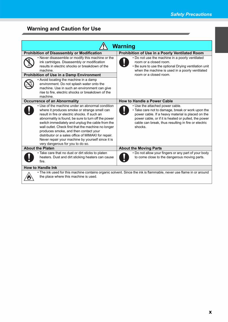
WarningProhibition of Disassembly or Modification Prohibition of Use in a Poorly Ventilated Room
• Never disassemble or modify this machine or the ink cartridges. Disassembly or modification results in electric shocks or breakdown of the machine.
• Do not use the machine in a poorly ventilated room or a closed room.
• Be sure to use the optional Drying ventilation unit when the machine is used in a poorly ventilated room or a closed room.Prohibition of Use in a Damp Environment
• Avoid locating the machine in a damp environment. Do not splash water onto the machine. Use in such an environment can give rise to fire, electric shocks or breakdown of the machine.
Occurrence of an Abnormality How to Handle a Power Cable• Use of the machine under an abnormal condition
where it produces smoke or strange smell can result in fire or electric shocks. If such an abnormality is found, be sure to turn off the power switch immediately and unplug the cable from the wall outlet. Check first that the machine no longer produces smoke, and then contact your distributor or a sales office of MIMAKI for repair. Never repair your machine by yourself since it is very dangerous for you to do so.
• Use the attached power cable.• Take care not to damage, break or work upon the
power cable. If a heavy material is placed on the power cable, or if it is heated or pulled, the power cable can break, thus resulting in fire or electric shocks.
About the Platen About the Moving Parts• Take care that no dust or dirt sticks to platen
heaters. Dust and dirt sticking heaters can cause fire.
• Do not allow your fingers or any part of your body to come close to the dangerous moving parts.
How to Handle Ink• The ink used for this machine contains organic solvent. Since the ink is flammable, never use flame in or around
the place where this machine is used.
xi
Precautions for Use
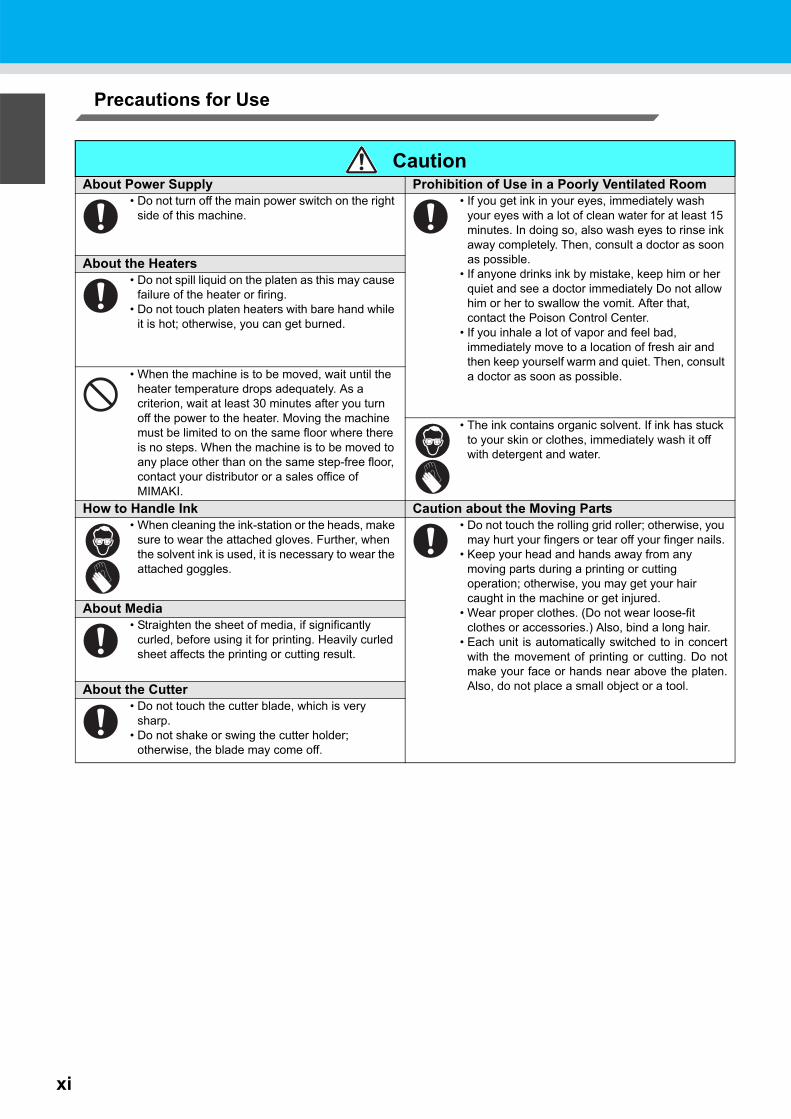
CautionAbout Power Supply Prohibition of Use in a Poorly Ventilated Room
• Do not turn off the main power switch on the right side of this machine.
• If you get ink in your eyes, immediately wash your eyes with a lot of clean water for at least 15 minutes. In doing so, also wash eyes to rinse ink away completely. Then, consult a doctor as soon as possible.
• If anyone drinks ink by mistake, keep him or her quiet and see a doctor immediately Do not allow him or her to swallow the vomit. After that, contact the Poison Control Center.
• If you inhale a lot of vapor and feel bad, immediately move to a location of fresh air and then keep yourself warm and quiet. Then, consult a doctor as soon as possible.
About the Heaters• Do not spill liquid on the platen as this may cause
failure of the heater or firing.• Do not touch platen heaters with bare hand while
it is hot; otherwise, you can get burned.
• When the machine is to be moved, wait until the heater temperature drops adequately. As a criterion, wait at least 30 minutes after you turn off the power to the heater. Moving the machine must be limited to on the same floor where there is no steps. When the machine is to be moved to any place other than on the same step-free floor, contact your distributor or a sales office of MIMAKI.
• The ink contains organic solvent. If ink has stuck to your skin or clothes, immediately wash it off with detergent and water.
How to Handle Ink Caution about the Moving Parts• When cleaning the ink-station or the heads, make
sure to wear the attached gloves. Further, when the solvent ink is used, it is necessary to wear the attached goggles.
• Do not touch the rolling grid roller; otherwise, you may hurt your fingers or tear off your finger nails.
• Keep your head and hands away from any moving parts during a printing or cutting operation; otherwise, you may get your hair caught in the machine or get injured.
• Wear proper clothes. (Do not wear loose-fit clothes or accessories.) Also, bind a long hair.
• Each unit is automatically switched to in concertwith the movement of printing or cutting. Do notmake your face or hands near above the platen.Also, do not place a small object or a tool.
About Media• Straighten the sheet of media, if significantly
curled, before using it for printing. Heavily curled sheet affects the printing or cutting result.
About the Cutter• Do not touch the cutter blade, which is very
sharp.• Do not shake or swing the cutter holder;
otherwise, the blade may come off.

xii
Safety Precautions
Cautions and Requests
WarningHow to Handle Ink Cartridges About the Clamp Lever
• Use the CJV30BS genuine ink. Remember that the user shall be responsible for repairing any damage resulting from the use of ink other than the genuine one.
• When any ink other than the CJV30BS genuine ink is used, the machine will not operate for its own protection.
• Do not use the CJV30BS genuine ink for other printers because doing so may cause the printers to break down.
• Never refill the ink cartridge with ink. Refilled ink cartridge can cause a trouble. Remember that MIMAKI assumes no responsibility for any damage caused by the use of the ink cartridge replenished with ink.
• If the ink cartridge is moved from a cold place to a warm place, leave it in the room temperature for three hours or more before using it.
• Open the ink cartridge just before installing it in the machine. If it is opened and left for an extended period of time, normal printing performance of the machine may not be ensured.
• Make sure to store ink cartridges in a cool and dark place.• Store ink cartridges and the waste ink tank in a place that
is out of the reach of children.• Be sure to thoroughly consume the ink in the ink cartridge,
once it is opened, within three months. If an extended period of time has passed away after opening the cartridge tank, printing quality would be poor.
• Neither pound the ink cartridge nor shake it violently, as doing so can cause leakage of ink.
• Do not touch or stain the contacts of the ink cartridge, as doing so may cause damage to the print circuit board.
• Waste ink is equivalent to waste oil of industrial waste. Request an industrial waste disposal company for disposal of waste ink.
• Never open the front cover or raise the lever during printing. Opening the cover or raising the lever will abort printing.
How to Handle Media• Use media recommended by MIMAKI to ensure reliable,
high-quality printing.• Set the heater temperature to meet the characteristics of
the media. Set the temperature of the Pre-heater, Print heater and Post-heater according to the type and characteristics of the media used. Automatic temperature setting can be made on the operation panel by setting the profile on the dedicated RIP. For setting on the RIP, refer to the instruction manual for your RIP.
• Pay attention to the expansion and contraction of the media. Do not use media immediately after unpacking. The media can be affected by the room temperature and humidity, and thus it may expand and contract.The media have to be left in the atmosphere in which they are to be used for 30 minutes or more after unpacked.
• Do not use curled media. The use of curled media can not only cause a media jam but also affect print quality. Straighten the sheet of media, if significantly curled, before using it for printing. If a regular-sized coated sheet of media is rolled and stored, the coated side has to face outside.
About Media and Dust• Store media in a bag. Wiping off dust accumulated on
media will adversely affect the media due to static electricity.
• When leaving the workshop after the working hours, do not leave any media on the roll hanger. If any media is left on the roll hanger, it can get dusty.
Caution about Maintenance• It is strongly recommended to use the machine in a room that is not dusty. Set the Refresh level 2 or 3 when the machine
is to be used in an unfavorable environment. ( P.3-34 "Setting of Refreshing")• Dust in the heads can also cause drops of ink to fall suddenly down on the media during printing. In such a case, be sure
to clean up the heads. ( P.3-28 "Setting Auto cleaning")• When cleaning the ink-station or the heads, make sure to wear the attached gloves. Further, when the solvent ink is used,
it is necessary to wear the attached goggles.• Perform wiping (removal of dust and paper powder) of the capping station and wiper frequently.
Periodic Replacement Parts• Some parts of this machine must be replaced with new ones periodically by service personnel. Be sure to make a contract
with your distributor or dealer for after sale service to ensure the long life of your machine.

Safety Precautions
xiii
Cautions about Installation
CautionA place exposed to direct sunlight On an inclined surface
A place where the temperature or humidity changes significantly
• Use the machine under the following environmental conditions:
•Operating environment: 20 to 35°C35 to 65% (Rh)
A place that vibrates A place exposed to direct air flow from an air conditioner, etc.
Around a place where fire is used

xiv
How to Read this Manual

xv

This chapter
describes the items required to understand before use, such as the name of each part ofthe machine or the installation procedures.
Moving This Machine.................................. 1-2Where to Install This Machine ..................... 1-2Working Environmental Temperature ......... 1-2Moving This Machine .................................. 1-3
Names of Parts and Functions .................. 1-4Front Side of the Machine ........................... 1-4Rear/Sides .................................................. 1-5Operation Panel .......................................... 1-6Heater ......................................................... 1-7Media Sensor .............................................. 1-7Carriage ...................................................... 1-8Capping Station ........................................... 1-9Pinch Rollers and Grid Rollers .................... 1-9Pen-line Rubber ........................................ 1-10
Media .......................................................... 1-11Usable Sizes of Media ...............................1-11Caution in Handling of Media .....................1-11
Connecting Cables.................................... 1-12Connecting USB2.0 Interface Cable ..........1-12Connecting the Power Cable .....................1-13
Inserting Ink Cartridges............................ 1-14Caution in Handling of Ink Cartridges ........1-15
Menu Mode ................................................ 1-16
Chapter 1Before Use

1-2
Moving This MachineWhere to Install This Machine
Secure a suitable installation space before assembling this machine.The place of installation must have enough space for not only this machine itself, but also for the printing andcutting operation.
Working Environmental TemperatureUse this machine in an environment of 20 to 35°C to ensure reliable printing.The heater temperature may not reach the set value, depending on the ambient temperature.
Model Width Depth Height Gross weightCJV30-60BS 1,524 mm 739 mm 1,424 mm 110 kg
CJV30-100BS 1,934 mm 739 mm 1,424 mm 130 kgCJV30-130BS 2,289 mm 739 mm 1,424 mm 145 kgCJV30-160BS 2,538 mm 739 mm 1,424 mm 160 kg
CJV30-60BS :2524 mmCJV30-100BS :2934 mmCJV30-130BS :3289 mmCJV30-160BS :3538 mm
500 mmor more
500 mmor more
1000 mm or more
1000 mm or more
2740 mmor more

Moving This Machine
1-3
1
Before U
se
Moving This MachineMove this machine according to the following steps when this machine needs to be moved on the same step-freefloor.
1 Unlock the casters.
2 Move this machine as shown in the figure.• For safety, be sure to operate it with 4 people or more.• Do not push the cover to move this machine since the cover
may be broken.
3 Lock the casters.
• When the machine is moved to any place other than on the same step-free floor, contact your distributoror our service office.If you move it by yourself, failure or damage may occur.Be sure to request your distributor or our service office to move this machine.
• When moving this machine, take care that it does not receive a significant impact.• Be sure to lock the casters after moving of this machine.

1-4
Names of Parts and FunctionsFront Side of the Machine
Tool trayA tool tray is provided so that you can put the small tools such as cutter knives, pens, etc. on it.
Carriage (printer unit)Moves the print head unit from side to side.
Operation panelThis panel has operation keys for configuring the settings needed for this machine and a display for showing the items to operate.
Clamp lever (front)Moves the pinch rollers up and down to hold or release the media.
Power switch*1
Turns ON/OFF the power to the machine.
Waste ink tankWaste ink gathers in this tank.
StandSupports the main body of the machine. It is provided with casters that are used to move this machine.
Take-up deviceAutomatically winds up the roll media printed.
Maintenance coverOpen the cover when carrying out maintenance. Even when the power switch is OFF, keep the cover closed.
PlatenThe printed media is printed out, sliding on the platen. Three heaters are installed inside the platen.
Print heater/Post-heaterFixes and dries the ink on the currently produced print. (Located inside the platen)
Ink cartridgeThe cartridge contains ink for each color.
Cartridge protection coverThis cover prevents an injury to the operator or the breakage of the machine caused by the protrusion of the cartridge. (It is located under the ink cartridge.)
*1 : The power switch under the operation panel lights up in green when the power is turned ON, and blinks when the power switch isturned OFF. The ink clogging prevention function is regularly performed even when the power switch is turned OFF with the mainpower switch ( P.1-5) kept ON. (Sleep function P.6-26)
Carriage (cutter unit)Moves the cutter head unit from side to side.

1-5
Names of Parts and Functions
1
Before U
se
Rear/Sides
Pre-heaterPreheats the media before printing. (Located inside the platen)
USB connectorThis is USB2.0 interface connector.
Roll holdersHolds a media by inserting it into the right and left ends of the core of the roll media. Roll holders are available for the 2 inches and 3 inches core of the roll media.
Clamp lever (rear)Interlocks with the clamp lever in the front of this machine.
Main power switchTurns ON/OFF the main power for this machine. Leave the main power turned ON to prevent ink clogging.
AC inletConnect the power cable to the AC inlet.
Cleaning solution cartridgeSet a dedicated Washings cartridge (optional).

1-6
Operation Panel
Jog key
Use these keys to shift the carriage or the media in [LOCAL]. Also use them to select an item from printing conditions.
keyUse this key to display the function setting menu.
keyCancels the last input value or returns the setting menu to the immediate higher level of the hierarchy.
Display
Displays the status of the machine, set items and errors.
key
Use this key to switch the modes between print mode (PRINT MODE lamp is ON) and cut mode (CUT MODE lamp is ON).
keyUse this key to switch between [LOCAL] and [REMOTE].
keyRegisters the last input value as the setting value or goes tothe immediate lower level of the hierarchy.
keyUse this key to check the prints forerrors in print mode and cut mode.
keyUse this key to set the temperatures for the Pre-heater, Print heater and Post-heater or check the current temperature of the platen.
keyUse this key to select a user type in print mode or to select a tool condition in cut mode.
keyUse this key to execute head cleaning when ink clogging occurs in print mode, or to feed the media in cut mode.
keyDeletes the data that has been received.
CONSTANT lampLights up in green when the heater temperature reaches the set temperature.
HEAT lampLights up in orange during heating up of the heater.

1-7
Names of Parts and Functions
1
Before U
se
HeaterPre-heater/Print heater/Post-heater are equipped on the platen.The Pre-heater is used for pre-heating of the media prior to printing to prevent rapid changes in temperature.The Print-heater improves the image quality in printing. The Post-heater dries ink after printing.
Media SensorThe media sensor detects the presence of the media and the medialength.This machine has a media sensor on the platen (in the rear).
• While the heater is on, the platen is very hot. When the front cover (Optional) is to be opened or mediais to be replaced, lower the heater temperatures and wait until the platen temperature drops; otherwise,you can get burned.
• When the media is to be replaced with a thin one, lower the heater temperatures and wait until theplaten temperature drops adequately. Setting a thin sheet of media while the platen is hot may causethe media to stick to the platen or cause wrinkling or curling of the media.
• Set the media so that the media sensor located in the rearof the platen is covered with the media without fail. Themedia cannot be detected unless it is placed over thesensor.
Post-heater Print heater Pre-heater
Media sensor

1-8
CarriageThe carriage consists of the printer unit and the cutter unit.
Printer Unit
Cutter Unit
Conjunct unit *1In concert with the data sent from a computer or the movement of the main body,switching is performed between printer unit and cutter unit.
Printer unitThe printer unit is used for printing.
Cutter unitThe cutter unit is used forcutting and printing with apen.
*1 When switching the conjunct unit to the printer unit with the cutter unit placed on the platen, the movement speed of the first 20cmbecomes slow to avoid injury from the cutter unit.
Height-adjusting leverA height-adjusting lever is provided to adjust the height of the Head in 2 stages according to the thickness of media. ( P.2-15)
ORIGIN markUse the ORIGIN mark as a marker for the origin position when using the printer unit
Tool holderAttach a tool for cutting mediato the tool holder.
Light pointerThe light pointer is used for detecting the register mark.
CutterThe cutter is used for cutting off media.

1-9
Names of Parts and Functions
1
Before U
se
Capping Station
The capping station consists of the ink caps, the wiper for cleaningthe heads, etc.The ink caps prevent the nozzles in the ink heads from drying up.The wiper cleans the nozzles in the heads.The wiper is consumable. If the wiper is deformed or the media isstained, replace the wiper with a new one. ( P.6-8)
Pinch Rollers and Grid RollersThis machine retains the media with the pinch rollers and the grid rollers.
• Be sure to wear the attached goggles in cleaning within the capping station to protect your eyes againstink.
• Do not switch manually the pressure mode switching lever and ON/OFF switching lever. Doing so maycause malfunctions to occur.
Wiper
Ink cap
Pressure mode switching leverThis lever changes the pressure to hold the media. For details onpressure setting, see P.3-6, P.4-3 "Setting for the Pinch Rollers".
ON/OFF switching leverThis lever switches the pinch rollers ON/OFF. For details on the setting,see P.3-6, P.4-3 "Setting for the Pinch Rollers".

Names of Parts and Functions
1-10
Pen-line RubberCutting and printing with a pen are performed on the pen line rubber.
If you want to perform dotted line cutting, follow the stepsbelow.
When performing dotted line cutting:
1 Remove the pen-line rubber.(1) Insert a flathead screwdriver or equivalent tool into
the gap between the left end of the pen-line rubber and the platen.
(2) Raise the pen-line rubber.
2 Install the pen-line sponge.(1) Align the right end of the pen-line sponge with the
right end of the platen.(2) Install the pen-line sponge.
Be careful of the following when installing the pen-line rubber.• When installing the pen-line rubber, make sure to push it into the slot softly and avoid stretching it
forcibly.• If pen line rubber is stretched forcibly, the edge of the pen line comes off and may decline the cutting
quality.• Store the replaced pen line.
• The pen-line sponge and pen-line sponge are consumable. Replace it with a new one if necessary.
Pen-line Rubber
Pen-line Rubber
Pen-line sponge

1-11
1
Before U
se
MediaUsable media sizes and notes for handling are described.
Usable Sizes of Media
Caution in Handling of MediaPay attention to the followings for handling of media.
Model CJV30-60BS CJV30-100BS CJV30-130BS CJV30-160BS
Type of recommended media
Whenprinting Tarpaulin / FF(Flexible Face) / Polyvinyl chloride film
Whencutting Chloroethene sheet / Fluorescent sheet / Reflection sheet
Maximum width 620 mm 1,030 mm 1,371 mm 1,620 mmMinimum width 100 mm 100 mm 100 mm 100 mmMaximum printing / cut width 610 mm 1,020 mm 1,361 mm 1,610 mm
Rol
l med
ia
Thickness 1.0 mm or lessRoll outside diameter φ180 mm or lessRoll weight 25 kg or lessRoll inside diameter 2 or 3 inchesPrint side Side facing outward
Roll end treatment The roll end is gently fixed to the core with weak-adhesive tape or weak glue for easy removal.
• Use media recommended by MIMAKI.Such media ensures reliable and high-quality printing.
• Set the heater temperature to meet the characteristics of the media.Set the temperature of the Pre-heater and Print heater according to the type and characteristics of themedia used. Automatic temperature setting can be executed on the operation panel by setting theprofile on the dedicated RIP. For the setting on the RIP, see the instruction manual for your RIP.
• Pay attention to the expansion and contraction of the media.Do not use media immediately after unpacking them. The media can be affected by the roomtemperature and humidity, and thus it may expand and contract. The media have to be left for 30minutes or more in the open air in the environment in which they are to be used after being unpacked.
• Do not use curled media.The use of curled media can cause a media jam. If a regular-sized coated sheet of media is rolled andstored, the coated side has to face outside.

1-12
Connecting CablesConnecting USB2.0 Interface Cable
Connect the PC and this machine with the USB2.0 interfacecable.
Notes on USB 2.0 Interface
When two or more CJV30BS machines are connected to one personal computer
Set the different "MACHINE NAME" for each connected CJV30BS. ( P.5-12)When two or more CJV30BS machines are connected to one personal computer, the personal computer may notrecognize all the CJV30BS machines normally.Reconnect the unrecognized CJV30BS machine to another USB port, if available, and check to see if it isrecognized. If the CJV30BS machine is not recognized by the newly connected USB port, use USB 2.0 repeatercables available on the market.
Notes on peripheral devices in USB high speed mode
When a peripheral device (USB memory or USB HDD) to be operated in USB high speed mode is connected tothe same personal computer that a CJV30BS machine is connected to, the USB device may not be recognized.When CJV30BS is connected to the personal computer to which an external HDD is connected via USB, thespeed of data output to CJV30BS may drop. That can cause the head unit to stop temporarily at the right or leftend during printing.
• Your application must be compatible with USB 2.0.
• Contact a RIP maker near your location or our office when the USB2.0 interface is not attached to the PC.
• Your application must be compatible with USB 2.0.
USB cable
USB2.0 repeater cable

Connecting Cables
1-13
1
Before U
se
Removing USB memory
If a USB memory module is inserted in the personal computer to which a CJV30BS machine is connected, click"Stop" in the "Safely Remove Hardware" window by following the instructions given there first and then removethe module.Leaving a USB memory module inserted can cause [ERROR 10 COMMAND ERROR].Copy the data onto the hard disk before outputting it for printing.
Connecting the Power Cable
1 Insert the power cable into an inlet of the machine.
2 Secure a cable band.• Secure the cable with the cable band attached to this
machine.
3 Insert the power plug into a plug socket.
• Do not use any power cables other than the attached power cable.
• Be sure to connect the power cable to the outlet near this machine, and make sure that the power cablecan be easily removed.
• Connect the power cable to the grounded outlet. Otherwise, it may result in fire or an electric shock.
Inlet
Power cable
Cable band
Power plug
Socket

1-14
Inserting Ink CartridgesInsert ink cartridges.
1 Shake the ink cartridge as shown on the right.
2 Insert the ink cartridge.• Insert the ink cartridge lengthwise with the surface having IC
chips pointing to the left side.• Colors are displayed on the display as follows.
Black: K, Cyan: C, Magenta: M, Yellow: Y
Changing an Ink CartridgePerform as follows when [INK END] or [NEAR END] is displayed on the display.
When [INK END] is displayed(1) Pull out the ink cartridge to be replaced.(2) Replace with a new ink pack and a new IC chip. (See the label attached on the eco case for
details.)(3) Insert an ink cartridge.
When [NEAR END] is displayedThere is a little ink left. Though printing can be continued even if it is displayed, it is recommended to replacethe ink cartridge as soon as possible to avoid running out of ink during printing.
• While [NEAR END] is displayed, the cleaning during printing does not work. ( P.3-26)

Inserting Ink Cartridges
1-15
1
Before U
se
For Ink Cartridge LampsThe condition of the ink cartridges set in the machine is confirmable with lamps located over the ink cartridges.
Caution in Handling of Ink Cartridges
Condition of Lamp Explanation
Upper rowRed lamp
OFF No error
Blinking
One of the following errors occurs.• Almost no ink• No ink• Expiration of a term of ink validity (one
month)
ON
One of the following errors occurs.• No ink left• No ink cartridge inserted• Other ink errors ( P.7-5)
Lower rowGreen lamp
OFF No error
ON
When used with 4-color ink set, themachine supplies ink from the inkcartridge with lower ink. In this case, thecartridge being used lights in green.
• The solvent ink contains organic solvent. If ink has stuck to your skin or clothes, immediately wash it offwith detergent and water. If you have gotten ink in your eyes, immediately wash your eyes with a lot ofclean water for at least 15 minutes. In doing so, also wash the back of the eyelids to rinse the ink awaycompletely. Then, consult a doctor as soon as possible.
• Use genuine ink cartridges for this machine. This machine functions by recognizing the genuine inkcartridges. In case of trouble caused by modified ink cartridges or the like, it shall be out of the warrantyeven within the warranty period.
• When the ink cartridge has been moved from a cold place to a warm one, leave it at room temperaturefor three hours or more before using it.
• Be sure to thoroughly use up the ink in the ink cartridge within three months of it being opened. If anextended period of time has passed after opening the cartridge, printing quality will deteriorate.
• Make sure to store ink cartridges in a cool and dark place.• Store ink cartridges in a place that is out of the reach of children.• Request an industrial waste disposal company to dispose of an empty ink cartridge.• Do not shake ink cartridges violently. This may result in ink leakage from the ink cartridges.• Never refill the ink cartridge with ink. A refilled ink cartridge can cause trouble. Remember that MIMAKI
assumes no responsibility for any damage caused by the use of an ink cartridge refilled with ink.• Do not touch or stain the contacts of the ink cartridge because doing so can cause damage to the print
circuit board.• Do not disassemble the ink cartridges.
Ink cartridge lamps

1-16
Menu ModeThis machine has 4 modes. Each menu mode is described below.
Not-ready
This is the mode in which the medium has not been detected yet.
• The keys other than the / key are effective.
LOCAL
LOCAL is the mode for the preparation state.There are two LOCAL modes: [Printer mode] and [Cutting mode].
• Press the key to switch to the printer mode and the cutting mode.• All the keys are effective.• The machine can receive data from the computer. However, it does not perform printing or cutting.
Function
To set Function mode, press the key when this machine is in Local mode.In this mode, printing conditions can be set.
REMOTE
The received data is printed or cut.Printing or cutting can be interrupted by pressing the key.
LOCAL display in printer mode
Displays current user type ( P.2-2).
Displays machine name ( P.5-12) to recognize the device.
Displays the detected medium width.
LOCAL display in cutting mode
Indicates that the machine is in cutting mode. Displays machine name ( P.5-
12) to recognize the device.
Indicates the current tool condition and set value ( P.2-3).

This chapter
describes procedures and setting methods for ink and media preparation, tool installationfor cutting, and printing and cutting.
User Type for Printing ................................ 2-2Settings That Can Be Registered in User Types .................................................. 2-2Using the Registered User Types ............... 2-2
About Tool Conditions during Cutting ..... 2-3Tool Condition Types and Their Selection Method ........................................................ 2-3Registering a Tool Condition ....................... 2-4Improving Cutting Quality ............................ 2-6
Operation Flow............................................ 2-7Turning the Power ON/OFF........................ 2-8
Turning the Power ON ................................ 2-8Turning the Power OFF ............................... 2-9
Installing Tools.......................................... 2-10When a Cutter Is Used .............................. 2-10Exchanging Tool ....................................... 2-13How to Attach a Ballpoint pen ................... 2-14
Setting a Medium ...................................... 2-15Adjusting the Head Height ........................ 2-15Adjusting the Position of the Pinch Roller According to the State of a Medium .......... 2-17Roll Stopper .............................................. 2-22Maximum Print Area/Cut Area .................. 2-23Notes When Using Medium Holder ........... 2-24Setting a Roll Medium ............................... 2-25Take-up Device ......................................... 2-29Setting a Leaf Medium .............................. 2-31When Changing the Origin ........................ 2-33
Test Printing .............................................. 2-35Test Printing ...............................................2-35Performing Head Cleaning ........................2-36
Test Cutting ............................................... 2-37Preparing for the Heaters ......................... 2-38
Changing the Temperature Settings for the Heaters ................................................2-38Checking the Heater Temperature ............2-39
Printing Data.............................................. 2-40Starting a Printing Operation .....................2-40Stopping a Printing Operation ....................2-41Deleting Received Data (Data Clear) ........2-41
Data Cutting............................................... 2-42Starting a Cutting Operation ......................2-42Stopping Cutting in a While .......................2-42Restarting a Cutting Operation ..................2-42Stopping a Cutting Operation (Data Clear) ...............................................2-43Removing the Cutter Unit Temporarily ......2-43
Cutting a Medium ...................................... 2-44
Chapter 2Basic Operations

2-2
User Type for PrintingRegister a printing condition according to each of the media that you use in a user type beforehand. When youreplace one medium with another, you can set the optimum printing condition only by changing one user type toanother.
Settings That Can Be Registered in User TypesFor the method of registering settings in user types (1 to 4), see P.3-2.
Using the Registered User Types
1 Press the key in LOCAL to select theprinting mode.
2 Press the key.
3 Press to selectone of the user types (1 to 4).
• You can also select one by pressing the key.
4 Press the key.
For Selecting a User Type without Using You can select a user type by using the key in the printer mode without pressing the key.
Settings Reference Page Settings Reference
PagePINCH ROLLER P.3-5 PRE-FEED
P.3-27MEDIA COMP. P.3-8 COLOR PATTERNDROP. POS CORRECT P.3-10 REFRESHHEATER P.3-12 VACUUMPRINT MODE P.3-16 FEED SPEED LEVELINK LAYERS P.3-27 PRIORITY P.3-22DRYING TIME P.3-20 AUTO CLEANING P.3-24AUTO CUT P.3-27 PRINT. CLEANING P.3-26
Press to select the printer mode.
Press to check [SETUP] and press
.
Press to select one of the user
types (1 to 4).Press .
< LOCA L . 1 > [ # 0 1 ]WI DTH : * * * * mm
USER TYPE CHANGETYPE ( 1 ) - > < 2 > : e n t
< LOCA L . 2 > [ # 0 1 ]WI DTH : * * * * mm
Number of the selected user type

2-3
2
Basic O
perationsAbout Tool Conditions during Cutting
Register a cutting condition according to each of the media that you use in a tool condition beforehand. Whenyou replace one medium with another, you can set the optimum cutting condition only by changing a toolcondition to another.
Tool Condition Types and Their Selection MethodA tool condition consists of a cutting condition and a printing-with-a-pen condition.You can select one tool condition by pressing the key and determine it by pressing the
key.For the method of registering tool conditions, see P.2-4.
For Selecting a Tool Condition without Using You can select a tool condition by using the key in the cutting mode without pressing the
key.
Type Explanation
CU
T1 to CU
T3
This is a tool condition when a cutter is used.
PEN
This is a tool condition when the pen is used.
HA
LFThis is a tool condition when dotted-line cutting is performed.
Press to select the cutting mode.
Press to check [SETUP] and press
.
Press to select a tool condition.
Press .
SPD PRS OFS[ CUT 2 ] 2 0 5 0 0 . 5 0
SPD PRS OFS[ CUT 3 ] 2 0 5 0 0 . 3 0
SPD PRS OFS[ CUT 1 ] 3 0 6 0 0 . 3 0
SPD PRS OFS[ PEN ] 3 0 8 0
SPD PRS OFS[ HA L F ] 2 0 4 0 0 . 3 0
Blade edgeOFFSET
Cutter holder
SPD * PRS OFS[ CUT 1 ] 3 0 6 0 0 . 3 0
OFFSETDistance between the center of the cutter holder and the edge of the cutter blade (mm)
PRESSURECutting pressure (g)
SPEEDCutting speed (cm/s)
This will be displayed in the following cases:When [CUT MODE] is set to “FINE” ( P.4-37)When [MEDIA TYPE] is set to “HEAVY” ( P.4-37)If “ * ” is displayed, the actual cutting speed is limited to 20cm/s.
SPD PRS[ PEN ] 3 0 8 0
OFFSET does not need to be set.
SPD PRS OFS[ HA L F ] 2 0 4 0 0 . 3 0
2-4
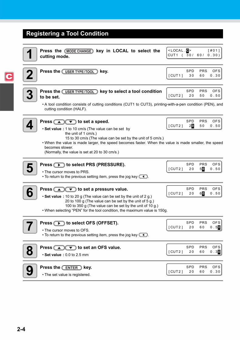
Registering a Tool Condition
1 Press the key in LOCAL to select thecutting mode.
2 Press the key.
3 Press the key to select a tool condition to be set.
• A tool condition consists of cutting conditions (CUT1 to CUT3), printing-with-a-pen condition (PEN), andcutting condition (HALF).
4 Press to set a speed.• Set value : 1 to 10 cm/s (The value can be set by
the unit of 1 cm/s.)15 to 30 cm/s (The value can be set by the unit of 5 cm/s.)
• When the value is made larger, the speed becomes faster. When the value is made smaller, the speedbecomes slower.(Normally, the value is set at 20 to 30 cm/s.)
5 Press to select PRS (PRESSURE).• The cursor moves to PRS.• To return to the previous setting item, press the jog key .
6 Press to set a pressure value.• Set value : 10 to 20 g (The value can be set by the unit of 2 g.)
20 to 100 g (The value can be set by the unit of 5 g.)100 to 350 g (The value can be set by the unit of 10 g.)
• When selecting “PEN” for the tool condition, the maximum value is 150g.
7 Press to select OFS (OFFSET).• The cursor moves to OFS.• To return to the previous setting item, press the jog key .
8 Press to set an OFS value.• Set value : 0.0 to 2.5 mm
9 Press the key.• The set value is registered.
< LOCA L . C > [ # 0 1 ]CUT 1 ( 3 0 / 6 0 / 0 . 3 0 )
SPD PRS OFS[ CUT 1 ] 3 0 6 0 0 . 3 0
SPD PRS OFS[ CUT 2 ] 2 0 5 0 0 . 5 0
SPD PRS OFS[ CUT 2 ] 2 0 5 0 0 . 5 0
SPD PRS OFS[ CUT 2 ] 2 0 5 0 0 . 5 0
SPD PRS OFS[ CUT 2 ] 2 0 6 0 0 . 5 0
SPD PRS OFS[ CUT 2 ] 2 0 6 0 0 . 5 0
SPD PRS OFS[ CUT 2 ] 2 0 6 0 0 . 3 0
SPD PRS OFS[ CUT 2 ] 2 0 6 0 0 . 3 0

2-5
About Tool Conditions during Cutting
2
Basic O
perations
• When the printing-with-a-pen condition (PEN) has been selected in Step 3, SPEED: 30 cm/s andPRESSURE: 60 to 80g should be handled as reference values.
• It is recommended to check whether the condition set by performing test cutting is proper after registering the tool condition. ( P.2-37)
• When a cutting condition (CUT 1 to 3 or HALF) has been set, the cutting and throwing-away (bladeedge direction alignment) operation ( P.4-38) is performed.
• When the PRESSURE value is set at less than 20 g in Step 7, the speed value in Step 5 needs to be setat 10 cm/s or less. Otherwise, the tool floats, and this causes letters to be blurred and cuttingremainders to be generated.
• With PRESSURE (cutting pressure) being set at a large value, do not make the cutting adjustment onlywith the length of the blade edge drawn out.When cutting is performed with the length of the blade edge drawn out being short and withPRESSURE being set at a large value, a strange sound may be made during cutting. In addition, thebottom surface of the cutter may rub against the sheet, causing the sheet surface to be damaged or thecutting quality to deteriorate.

About Tool Conditions during Cutting
2-6
Improving Cutting QualityCutting quality can be improved by reducing the level of acceleration speed for cutting.
1 Press the key in LOCAL to select the cut-ting mode.
2 Press the key.
3 Press the key.
4 Press to set the speed reduction level.
• Setting value: 10 to 100% (10% step)• The acceleration speed when the speed reduction level is set to 100% is displayed in the upper part of the
display. Even if the speed reduction level is set to lower, the acceleration speed displayed in the upper partof the display will not be renewed.
L
5 Press the key.
• The set value will be registered.
Relationships between cutting speed and acceleration speed
• If you set the speed reduction level, cutting speed will become slower. (Minimum operation acceleration speed: 0.1G)
ItemCUT MODE • When pen pressure (PRS) is set to 150g or
higher, the acceleration speed will be 0.2G lower than the value indicated in the table shown on the left.
FINE STANDARD FAST
Speed [cm/s]1 ~ 5 0.4 [G] 0.6 [G] 0.8 [G]6 ~ 15 0.5 [G] 0.7 [G] 0.9 [G]
20 ~ 30 0.6 [G] 0.8 [G] 1.0 [G]
< LOCA L . C > [ # 0 1 ]CUT 1 ( 3 0 / 6 0 / 0 . 3 0 )
SPD * PRS OFS[ CUT 1 ] 3 0 6 0 0 . 3 0
( 1 0 0% = 0 . 5G )[ CUT 1 ] ACC . L v . = 1 0 0%
( 1 0 0% = 0 . 5G )[ CUT 1 ] ACC . L v . = 8 0%

2-7
2
Basic O
perations
Operation FlowPrint Print & Cut Cut
Installing tools
Selecting a user type
Selecting a tool condition
Cutting
Setting the heaters
Test printing
Printing
Turning the power ON
Setting media
Test cutting
Refer to P. 2-8 "Turning the Power ON/OFF".
Refer to P. 2-37.
Refer to P. 2-10 "Installing Tools".
Refer to P. 2-15 "Setting a Medium".
Refer to P. 2-2 "User Type for Printing".
Refer to P. 2-3 "About Tool Conditions during Cutting".
Refer to P. 2-42 "Data Cutting".
Refer to P. 2-38 "Preparing for the Heaters".
Refer to P. 2-35 "Test Printing".
Refer to P. 2-40 "Printing Data".

2-8
Turning the Power ON/OFFTurning the Power ON
This machine is provided with the following two power switches:Main power switch : It is located on the side of this machine. Keep this switch ON all the time.Power switch : Normally, use this switch to turn the power ON/OFF.
The power switch lights in green when the power is ON and blinks in green when it isOFF.The nozzle clogging prevention function periodically operates even with the powerswitch turned OFF when the main power switch is turned ON (the power switch blinks ingreen).
1 Turn the main power switch ON.• Set the main power switch located on the side of this machine
to the “I” side.
• The firmware version is displayed when the power is turned ON.
• The machine performs its initial operation.• When the main power switch is turned on, the printer unit will go
and return once on the platen.
2 The machine enters LOCAL.
3 Turn ON the power of the connected PC.
• The head nozzle may result in nozzle clogging if the main power switch is left OFF for a long time.
Main power switch
C J V 3 0 - 6 0 BS V * . * *
P L EASE WA I T
< LOCA L . 1 > [ # 0 1 ]

Turning the Power ON/OFF
2-9
2
Basic O
perations
Turning the Power OFFWhen having ended the operation of the machine, turn the power OFF by pressing the power switch located onthe front side. Check the following items when turning the power OFF.
• If the machine is receiving data from the PC or if there is any data that has not been output yet• If the head has returned to the capping station• If any error has occurred ( P.7-10 "Error Messages")
1 Turn OFF the power of the connected PC.
2 Press the power switch to turn the power OFF.• The power switch blinks in green.• Do not turn OFF the main power switch located on the side of
the machine.• To use this machine again, light the green lamp by pressing the
power switch.• When the conjunct unit is connected to the cutter unit, after
being connected to the printer unit, the power turns OFF.
Cautions about Turning the Power OFF
Do not turn the main power switch OFF.When the main power switch is ON, the power periodically turns ON and the nozzle clogging preventionfunction (flushing function) operates. When the main power switch has been turned OFF, the sleep functions, such as flushing, do not operate,and this may cause nozzle clogging.
Turn the power OFF after having checked the position of the print unit.If the power is turned OFF in a state where the print unit has not returned to the capping station, the inkhead dries, which may cause nozzle clogging. In this case, turn the power ON again and check that the print unit has returned to the capping station, andthen turn the power OFF.
Do not turn the power OFF during printing or cutting.The head may not return to the capping station.
After having turned the power switch OFF, turn the main power switch OFF.When turning the main power switch off for moving the machine or for solving the error or the like, pressthe power switch on the front of the machine, check the display is turned off on the operation panel, andthen turn the main power switch off.
Power switch

2-10
Installing ToolsThis machine allows you to use the following tools:
Cutter : This tool is selected when an image printed on a medium is cut or whenletters are cut with a cutting medium.
Pen (water-based ballpoint pen) : This tool is used to perform “test printing” for checking how images orletters are cut actually.
When a Cutter Is Used
Mounting a Cutter Blade
1 Remove the cutter holder.
2 Loosen the locknut and remove the adjustment knob from the holder.
3 Insert a cutter blade in the hole of the adjustment knob.
• Pick up the cutter blade with tweezers.
4 Tighten the locknut.
• Do not touch the cutter with your fingers.The sharp blade edge of the cutter may cause you to get injured.
• Do not shake the tool after having set the cutter.Otherwise, the blade edge may pop out, causing you to get injured.
• Store the cutter blade in a place that is out of the reach of children.In addition, dispose of used cutter blades according to regional laws and regulations.
Locknut
Adjustment knob

2-11
Installing Tools
2
Basic O
perations
Adjusting the Blade EdgeThe blade edge needs to be adjusted according to the type of cutter and medium you use.After having adjusted the blade edge, set cutting conditions and conduct test cutting to check how the cutter cuts.
1 Remove the cutter holder and loosen the locknut.
2 Rotate the adjustment knob and adjust the length of the blade edge drawn out.
3 Tighten the locknut.• Tighten the adjustment knob until
it does not rotate any further.
Adjust the length of the blade edge
• Be careful that the length of the blade edge is not too long. When the blade edge is too long, the cuttermay cut the backing paper through and damage the machine.
• For the blade edge adjustment of cutters other than ones supplied with this machine, see the Appendix.( P. 6-46)
Locknut
Adjustment knob
Depth of the blade edge that cuts in =
Reference:Length of the blade edge drawn out = 0.3 to 0.5 mm (When the blade edge cuts badly, replace the bladewith another.)
• Adjust the pressure so that the backing paper has a little cutting streak.• When the backing paper thickness is less than the film thickness and, therefore, accurate cutting
quality cannot be obtained, changing the length of the blade edge may produce a good result.
Length of the blade edge drawn out
Depth of the blade edge that cuts in
FilmBacking paper
(Film thickness + Backing paper thickness)
2• However, when film thickness is less than backing
paper thickness:

2-12
Installing the Cutter Holder
1 Insert the cutter holder into the tool holder.
• Press the cutter brim on the tool holder.
2 Fix the cutter holder.• Rotate the knob of the tool holder clockwise and fix the tool
firmly.
• Insert the cutter holder firmly so that there is no space under the holder.
• Fix the cutter holder firmly. When the cutter holder has been fixed loosely, no accurate cutting (printing-with-a-pen) quality can be expected.
Brim
Knob

2-13
Installing Tools
2
Basic O
perations
Exchanging Tool
1 Press the key in LOCAL to select cuttingmode.
2 Press the key.
3 Press to select [MAINTENANCE].
4 Press the key.
5 Press to select [TOOL REPLACE].
6 Press the key.
7 Press the key.• The cutter unit moves to the left end of the machine.• Now the cutter unit can be moved manually. Move the cutter unit to the position where you can assure
easy access, and then replace the blade edge.
8 See P.2-12 "Installing the Cutter Holder" to replace the cutter holder.• When exchanging the cutter blade, refer to P.2-10 "Mounting a Cutter Blade".• Adjust the length of the blade edge as required. ( P. 2-11)
9 When replacement is finished, press the key.
• Do not touch until the cutter unit stops.
< LOCA L . C > [ # 0 1 ]CUT 1 ( 3 0 / 6 0 / 0 . 3 0 )
FUNCT I ON CSETUP < ENT >
FUNCT I ON CMA I NTENANCE < ENT >
MA I NTENANCEMARK SENSOR < e n t >
MA I NTENANCETOOL REP L ACE < e n t >
TOOL REP L ACEACT I ON : e n t

Installing Tools
2-14
How to Attach a Ballpoint pen
1 Put the cap on the pen adaptor.• The cap is used to adjust the height of the pen.
2 Insert a pen into the pen adaptor.• Insert the pen until the point of the pen touches the cap.
3 Fix the point of the pen.• Tighten the fixing screw clockwise.• Be careful not to turn the fixing screw of the pen adaptor too tight.
Otherwise, the ballpoint pen may break.
4 Remove the cap.
5 Insert the pen adaptor to which the pen has been attached into the tool holder.
• Press the brim of the pen adaptor on the tool holder.• Set the pen adaptor so that the fixing screw does not touch
anything.
6 Fix the tool.• Turn the knob of the tool holder clockwise
and fix the tool firmly.
• When you use a ballpoint pen sold on the market, use one with a diameter of 8 to 9 mm. Image qualitymay change, depending on the pens to be used.(Recommended ballpoint pen: K105-A and K105-GA (product No.) manufactured by Pentel Co., Ltd.)
• Ballpoint pens shown right may lean over and make contact withthe cover when they are held by the pen adaptor. (Pen whose penholder's diameter changes, depending on its parts/Pen that hasprojections or steps on its pen holder)
Pen whose pen holder diameter changes,
depending on its parts
Pen that has projections or steps
on its pen holder
Pen
Pen adaptor
Fixing screw
Cap
Insert the pen until the point of the pen touches the pen adaptor.

2-15
2
Basic O
perations
Setting a MediumThis machine can be used with a roll medium and leaf medium.For usable media, refer to P.1-11 "Usable Sizes of Media".
Adjusting the Head HeightAdjust the head height according to the thickness of the medium you use.
1 Move the carriage to the platen.• When the device is turned ON:
Execute [ST.MAINTENANCE - CARRIAGE OUT] of theMaintenance functions.( P.6-6 Steps 1 and 2)
• When the device is turned OFF:Move the carriage by hand.
2 Loosen the two screws located at the front.
• Loosen the screws, rotating each by one turn of a screwdriver.
3 Adjust the height-adjusting lever according to the medium.
• Adjust the position of the lever, referring to "For the Adjusting Lever and the Range".
• Set the height-adjusting lever to the highest stage or the lowest stage. Setting it to the intermediate height, a printing fault can result.
4 While keeping the height-adjusting lever held atthe aforementioned position, tighten the twoscrews.
• Be sure to fasten the screws, pressing the height-adjustinglever, otherwise the head cannot be secured at the correctposition.
• Fasten the screws securely.
• Adjust the head height prior to setting the medium. If the head height is adjusted after the medium is set,this may cause a medium jamming, deterioration of the print quality or head damage.
• If the drawing quality is set to "Bi-D" ( P.3-18), perform "Dot position correction" of the maintenancefunction after the head height is adjusted. ( P.3-10).
Carriage
Screws
Height-adjusting lever

2-16
5 Return the carriage to the station position.
For the Adjusting Lever and the Range
Height-adjusting lever Head height Switching area
Thin 2 mm(The set position before shipping) Switch by user
Thick 3 mm
• Set the lever to "Thick" when a thicker medium such as tarpaulin or FF is used.• Set the lever to "Thick" when the medium is prone to gather dust in the head or is often stained with ink
traces.

2-17
Setting a Medium
2
Basic O
perations
Adjusting the Position of the Pinch Roller According to the State of a MediumAdjust the position of the pinch roller according to the width of the medium to be set.This machine feeds the medium with a pinch roller and grid roller for printing or cutting. The pinch roller should be above the grid roller.
How to Adjust the Pinch RollerMove the pinch roller unit to adjust the position of the pinch roller.Use the pinch roller guide mark for positioning.
Pinch roller
Grid roller
Pinch roller guide markTo adjust the pinch roller from the front side:
To adjust the pinch roller from the rear side:
Pinch roller unit (top view)Adjust the pinch roller so that the triangle mark comes between the pinch roller guide marks.
Pinch roller unit (rear side)

2-18
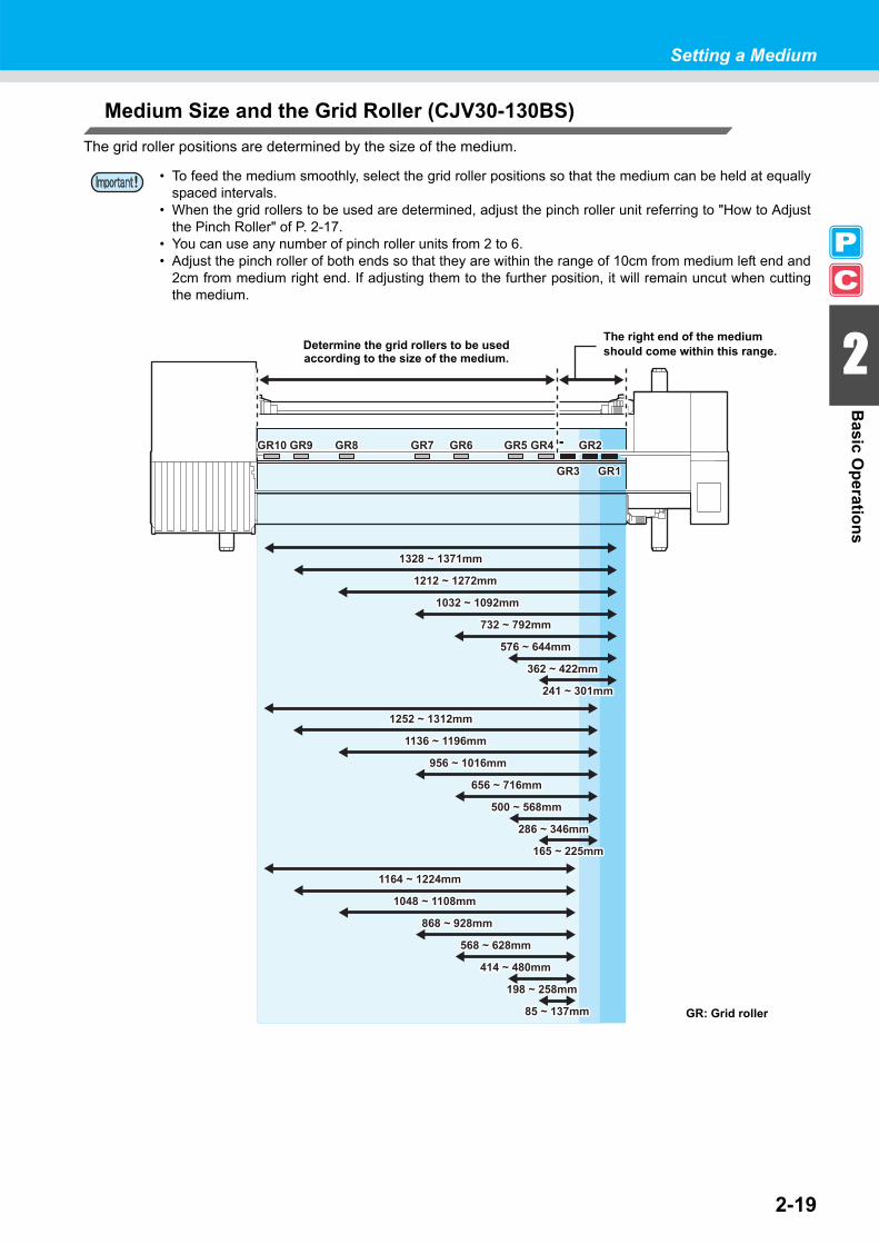
Medium Size and the Grid Roller (CJV30-160BS)The grid roller positions are determined by the size of the medium.
• To feed the medium smoothly, select the grid roller positions so that the medium can be held at equallyspaced intervals.
• When the grid rollers to be used are determined, adjust the pinch roller unit referring to "How to Adjustthe Pinch Roller" of P. 2-17.
• You can use any number of pinch roller units from 2 to 7.• Adjust the pinch roller of both ends so that they are within the range of 10cm from medium left end and
2cm from medium right end. If adjusting them to the further position, it will remain uncut when cuttingthe medium.
1577 ~ 1620mm1577 ~ 1620mm
1446 ~ 1514mm1446 ~ 1514mm
1212 ~ 1272mm1212 ~ 1272mm
1032 ~ 1092mm1032 ~ 1092mm
732 ~ 792mm732 ~ 792mm
576 ~ 644mm576 ~ 644mm
364 ~ 424mm364 ~ 424mm
241 ~ 301mm241 ~ 301mm
1501 ~ 1561mm1501 ~ 1561mm
1370 ~ 1438mm1370 ~ 1438mm
1136 ~ 1196mm1136 ~ 1196mm
956 ~ 1016mm956 ~ 1016mm
656 ~ 716mm656 ~ 716mm
500 ~ 568mm500 ~ 568mm
288 ~ 348mm288 ~ 348mm
165 ~ 225mm165 ~ 225mm
1413 ~ 1473mm1413 ~ 1473mm
1284 ~ 1350mm1284 ~ 1350mm
1048 ~ 1108mm1048 ~ 1108mm
868 ~ 928mm868 ~ 928mm
568 ~ 628mm568 ~ 628mm
414 ~ 480mm414 ~ 480mm
200 ~ 260mm200 ~ 260mm
85 ~ 137mm85 ~ 137mm
GR1GR1
GR2GR2GR4GR4
GR3GR3
GR11GR11 GR10GR10 GR5GR5GR6GR6GR7GR7GR8GR8GR9GR9
Determine the grid rollers to be usedaccording to the size of the medium.
The right end of the medium should come within this range.
GR: Grid roller
2-19
Setting a Medium
2
Basic O
perations
Medium Size and the Grid Roller (CJV30-130BS)The grid roller positions are determined by the size of the medium.
• To feed the medium smoothly, select the grid roller positions so that the medium can be held at equallyspaced intervals.
• When the grid rollers to be used are determined, adjust the pinch roller unit referring to "How to Adjustthe Pinch Roller" of P. 2-17.
• You can use any number of pinch roller units from 2 to 6.• Adjust the pinch roller of both ends so that they are within the range of 10cm from medium left end and
2cm from medium right end. If adjusting them to the further position, it will remain uncut when cuttingthe medium.
1328 ~ 1371mm1328 ~ 1371mm
1212 ~ 1272mm1212 ~ 1272mm
1032 ~ 1092mm1032 ~ 1092mm
732 ~ 792mm732 ~ 792mm
576 ~ 644mm576 ~ 644mm
362 ~ 422mm362 ~ 422mm
241 ~ 301mm241 ~ 301mm
1252 ~ 1312mm1252 ~ 1312mm
1136 ~ 1196mm1136 ~ 1196mm
956 ~ 1016mm956 ~ 1016mm
656 ~ 716mm656 ~ 716mm
500 ~ 568mm500 ~ 568mm
286 ~ 346mm286 ~ 346mm
165 ~ 225mm165 ~ 225mm
1164 ~ 1224mm1164 ~ 1224mm
1048 ~ 1108mm1048 ~ 1108mm
868 ~ 928mm868 ~ 928mm
568 ~ 628mm568 ~ 628mm
414 ~ 480mm414 ~ 480mm
198 ~ 258mm198 ~ 258mm
85 ~ 137mm85 ~ 137mm
GR1GR1
GR2GR2GR4GR4
GR3GR3
GR10GR10 GR5GR5GR6GR6GR7GR7GR8GR8GR9GR9
Determine the grid rollers to be usedaccording to the size of the medium.
The right end of the medium should come within this range.
GR: Grid roller

2-20
Medium Size and the Grid Roller (CJV30-100BS)The grid roller positions are determined by the size of the medium.
• To feed the medium smoothly, select the grid roller positions so that the medium can be held at equallyspaced intervals.
• When the grid rollers to be used are determined, adjust the pinch roller unit referring to "How to Adjustthe Pinch Roller" of P. 2-17.
• You can use any number of pinch roller units from 2 to 4.• Adjust the pinch roller of both ends so that they are within the range of 10cm from medium left end and
2cm from medium right end. If adjusting them to the further position, it will remain uncut when cuttingthe medium.
973 ~ 1030mm973 ~ 1030mm
900 ~ 960mm900 ~ 960mm
732 ~ 792mm732 ~ 792mm
576 ~ 644mm576 ~ 644mm
364 ~ 424mm364 ~ 424mm
241 ~ 301mm241 ~ 301mm
897 ~ 957mm897 ~ 957mm
824 ~ 884mm824 ~ 884mm
656 ~ 716mm656 ~ 716mm
500 ~ 568mm500 ~ 568mm
288 ~ 348mm288 ~ 348mm
165 ~ 225mm165 ~ 225mm
809 ~ 869mm809 ~ 869mm
736 ~ 796mm736 ~ 796mm
568 ~ 628mm568 ~ 628mm
414 ~ 480mm414 ~ 480mm
200 ~ 260mm200 ~ 260mm
85 ~ 137mm85 ~ 137mm
GR1GR1GR2GR2GR4GR4 GR3GR3GR5GR5GR6GR6GR7GR7GR8GR8GR9GR9
Determine the grid rollers to be usedaccording to the size of the medium.
The right end of the medium should come within this range.
GR: Grid roller

2-21
Setting a Medium
2
Basic O
perations
Medium Size and the Grid Roller (CJV30-60BS)The grid roller positions are determined by the size of the medium.
• To feed the medium smoothly, select the grid roller positions so that the medium can be held at equallyspaced intervals.
• When the grid rollers to be used are determined, adjust the pinch roller unit referring to "How to Adjustthe Pinch Roller" of P. 2-17.
• Be sure to prepare two or more pinch roller units.• Adjust the pinch roller of both ends so that they are within the range of 10cm from medium left end and
2cm from medium right end. If adjusting them to the further position, it will remain uncut when cuttingthe medium.
364 ~ 424mm364 ~ 424mm
241 ~ 301mm241 ~ 301mm
563 ~ 620mm563 ~ 620mm
480 ~ 547mm480 ~ 547mm
288 ~ 348mm288 ~ 348mm
165 ~ 225mm165 ~ 225mm
399 ~ 460mm399 ~ 460mm
200 ~ 260mm200 ~ 260mm
85 ~ 137mm85 ~ 137mm
GR1GR1GR2GR2GR4GR4 GR3GR3GR5GR5GR6GR6
Determine the grid rollers to be used according to the size of the medium.
The right end of the medium should come within this range.
GR: Grid roller

2-22
Roll StopperWhen the medium is set and a certain amount is pulled out, the roll stopper function is activated to stop the rollholder temporarily. This function is provided to prevent unnecessary pull-out of the medium.
Locking the roll stopper manuallyDepending on the roll holder set location, the roll stopper arm may not be able to lock the roll stopper. In this case,follow the steps below to lock the roll stopper.
1 Pull the roll stopper in the directionshown right.
2 Press the lock pin to hold the roll stopper.
• The roll stopper works with the clamp lever. Do not push the clamp lever down while the roll stopper iscaught between the roll stopper arm and the this machine. The roll stopper arm might be broken and theroll stopper function might be disabled.
Roll stopper arm
Roll stopper
Rollholder
Rollholder
Main body of
the machine
Main body of
the machine
Lock pin
Roll stopper

2-23
Setting a Medium
2
Basic O
perations
Maximum Print Area/Cut AreaThe maximum printed area/cut area varies, depending on the position of the pinch roller( P.2-18 to P.2-21)and the origin position ( P.2-33). The white area shown in the following figure represents the maximum print/cut area.The area other than that is the dead space that cannot be printed/cut.
Expand the maximum printed/cut area with the Expand function of the Common settings
Notes While Expand Function Is ON
CJV30-60BS CJV30-100BS CJV30-130BS CJV30-160BSMaximum printing/cut width 610 mm 1,020 mm 1,361 mm 1,610 mm
• The recommended dead space in the front end is 40 mm or more. (Turn the expand function "OFF"P.5-6) If the dead space in the front end is too small, the media may become loose. This affects
print or cut quality.
• While the expand function is ON, keep the end of the medium holder from coming in contact with the pinch holder. It will cause the stain on the medium when printing.
• Make a clearance of 1 mm or above between the end of the medium holder and the pinch holder.
Expand OFF Expand ON
Dead space in the rear end98.5 mm
Pinch roller
Dead space in the front: 40 mm Dead space in the front: 40 mm
Printing/cutting width
Printing/cutting width
Origin Origin
Cut
leng
th
Cut
leng
th
* Dead space:Area that cannot be printed or cut
5 mm or more
5 mm or more
1mm or above
5mm or above

2-24
Notes When Using Medium Holder
Setting Position of the MediumSet the medium so that the right end of the medium will be inside the area shown below.
The End of the Medium Should Not Exceed the Slit Line on the Platen
• If the medium is set with its end exceeding the slit line on the platen, the medium may be lifted when it isfed obliquely. This may cause damage to the head.
Set the medium so that the right end of the medium will be inside the area shown by an arrow. (up to the 3rd grid roller from the right end in front of the main body)
Medium
Medium holder
Slit line

2-25
Setting a Medium
2
Basic O
perations
Setting a Roll MediumSet a roll medium to the roll media hanger located on the back of this machine.
1 Move the roll holder located in the back of thedevice in the direction of the middle of the device.
• Loosen the roll holder fixing screw and then move it.
2 Check that the clamp lever is lowered.
3 Move the roll holder to the roll setting position.• Check the medium size and the position to set the medium, referring to the section applicable to your
machine ( P.2-18 to P.2-21).
• Check that the roll stopper is not caught between the roll stopper arm and this machine.• If the roll stopper arm and the roll stopper are interlocked and they don't move, enable the roll stopper
function manually. ( P.2-22)
• Take care not to drop the medium on your foot when setting the medium. It may cause an injury due tothe medium.
• If the cutter unit is on the platen, press the key to evacuate the cutter unit. ( P.2-43)
Roll holder fixing screw
Roll holder
Adjust the basic position of the roll holder so that it is placed between the guide marks of the pinch rollers.
Setting position of 2 inch tube
Roll holder side (The back of this machine)
Setting position of 3 inch tube

2-26
4 Tighten the roll holder fixing screw.• Check the Steps 2 to 3 again.
5 Set the left end of the core of the roll medium on the left roll holder.
• Push the roll medium onto the roll holder until the roll core isall the way seated.
6 Loosen the screw of the right side roll holder, then insert the holder into the core of the roll medium.
7 Raise the clamp lever in the rear side of this machine.
• When the setting of the pinch roller pressure is “OFF”( P.3-6, P.4-3), raising the clamp lever will change thesetting from “OFF” to “LOW”. (Because the medium will besurely held when changing the medium size.)
8 Insert the roll medium in this machine.
• The roll medium can be smoothly inserted by slanting the medium.(1) Pull the medium out of the roll to the head of the platen.(2) Insert the medium between the platen and the pinch roller units.
• Pull the medium out of the roll so that the medium can be grasped from the front of the machine.(3) Push down the clamp lever from the back of this machine.
• The medium is held.
• Set the pinch roller units so that the medium can be held at equally spaced intervals. If the pinch rollerscannot be set at equally spaced intervals, start over from Step 3.
• Ensure there is a dead space of 5 mm or above at each end of the medium.
Clamp lever
Pinch roller unit

2-27
Setting a Medium
2
Basic O
perations
9 Pull out the roll medium out.(1) Raise the clamp lever from the front of this machine.(2) Pull out the roll medium gently and then stop pulling
when locked lightly.
10 Make the roll medium even, then lower the clamplever.
• Pulling several positions of the medium lightly, lower the clamp lever after confirming that the amount of the roll medium pulled out is almost even.
11 For printing, clip lightly the medium with the medium holder.
• When using a thick medium, remove the medium holder fromthe medium before printing.
• When setting the medium holder, refer to P.2-24.• You do not need to use the medium holder for cutting.
12 Prepare the take-up device.• Set an empty core of the roll medium on the take-up device.
13 Press to set the number of the pinch roller atthe left end of the medium.
• Set the number of the pinch roller at the left end of the set medium.• Press to skip the pinch roller pressure setting from Step 14 to Step 17.
Medium holder
Core
Take-upDevice
* * P I NCH ROL L ER * *P I NCH ROL L ER : No . 7 t o 1

2-28
14 Press the key.
15 Check the current pinch roller pressure.• To change the set pinch roller pressure temporarily, follow the steps below.(1) Press to select a pinch roller to set.(2) Press to set the pressure.
16 Press the key.
17 Press the key to select "ROLL".• Detects the medium width.• When "Remaining amount of a medium to display" of the maintenance function is "ON" ( P.6-37), the
screen for entering medium remaining amount is displayed after detecting the medium width. ( P.2-29)
18 Secure the medium on the take-up device.( P.2-29)
(1) Feed the medium up to the core of the roll medium of the take-up device by pressing the key.
(2) Fix the middle of the medium with adhesive tape.(3) In the same manner, fix the left side and right side of the
medium.• Make sure that there is no slack or wrinkle on the
medium by pulling it to the right and left evenly, and thenfix it with a piece of tape.
• Once a printing condition or a cutting condition appropriate to the media is registered when setting thetype and the tool condition, setting the pinch roller on Step 13 to 15 is not needed.
• When performing the settings for the first time, the values displayed in step 14 display the valuesconfigured by the type registration and tool conditions.
• The value set in Steps 13 to 16 will be held until the power is tuned OFF or until the function "Setting forthe pinch rollers" ( P.3-5 and P.4-2) is changed.
• The value set here will be displayed next time when the medium is set.• The setting for the pinch roller can be canceled when the medium is set, using the common settings
"Setting for the pinch rollers" ( P.5-3).
> PR I NT [ MMMMMMM ]CUT [ H_ _ _ _ _H ]
Current mode and pinch roller pressure is indicated with [>].
MED I A SE L ECTROL L < > L EAF

2-29
Setting a Medium
2
Basic O
perations
Entering the Medium Remaining AmountWhen "Remaining amount of a medium to display" of the maintenance function is "ON" ( P.6-37), the screenfor entering medium remaining amount is displayed after detecting the medium width.
1 Display the screen for entering medium remainingamount.
2 Press keys to enter the medium remaining amount.
3 Press the key.
Take-up Device
Adjusting the switchThe take-up direction of the medium is selectable by using the switchof the take-up device.
Lever in top position (REVERSE) : The take-up device winds the medium with the printed side facing in.
Lever in middle position (OFF) : The take-up device does not wind the medium.
Lever in bottom position (FORWARD) : The take-up device winds the medium with the printed side facing out.
• The medium remaining amount can be entered only when a medium or a roll is detected in the printermode.
I n p u t o f Me d i a L e n g t hMED I A L ENGTH = * * * . * m
I n p u t o f Me d i a L e n g t hMED I A L ENGTH = 5 0 . 0m

2-30
Setting the Torque LimiterThe take-up device is provided with a torque limiter. The take-up torque can be adjusted with the torque limiter.(The torque limiter is set at the maximum value when shipped from the factory.)In the following cases, make the adjustment:
(1) when the tension is too strong in using thin medium(2) when performing combined operation of print & cut
• A clockwise turn : Increases torque (a heavy and thicker medium such as tarpaulin or the like)• A counterclockwise turn : Decreases torque (for light medium)
When Not Using Taking-up Device
• When the torque limiter is adjusted too weak:The medium cannot be taken up firmly.
• When the torque limiter is adjusted too strong:Slack may occur depending on the medium and have an influence on the image quality.In addition, when performing combined operation of print & cut and when making the medium return tothe cutting start position, it may not return to the origin of the resister mark after printing is completed.
• When performing printing or cutting of 700 mm or morewithout using the taking-up device, evacuate the taking-up device to right and left. The quality of the print and cutmay become low because of the impact when the frontend of the medium touches the taking-up device. (Sameas when fixing the optional dry evacuation unit)
50% of the maximum torque 100% of the maximum torqueTorque indicator
Adjustment nut

2-31
Setting a Medium
2
Basic O
perations
Setting a Leaf MediumUnlike a roll medium, a leaf medium does not need to be retained with the roll holders.
1 Raise the clamp lever.• When the setting of the pinch roller pressure is “OFF”
( P.3-6, P.4-3), raising the clamp lever will change thesetting from “OFF” to “LOW”. (Because the medium will besurely held when changing the medium size.)
2 Insert the leaf medium between the platen and the pinch rollers.
• Check the medium size and the position to set the medium,referring to the section applicable to your machine ( P.2-18 to P.2-21).
3 For printing, clip lightly the medium with the medium holder.
• When using a thick medium, remove the medium holder fromthe medium before printing.
• When setting the medium holder, refer to P.2-24.• You do not need to use the medium holder for cutting.
4 Push down the clamp lever.• Set the medium straight.
• If the cutter unit is on the platen, press the key to evacuate the cutter unit. ( P.2-43)
• Set the pinch roller so that the medium is held at equally spaced intervals. If the pinch rollers cannot beset at equally spaced intervals, start over from Step 2.
• Ensure there is a dead space of 5 mm or above at each end of the medium.
Clamp lever
Pinch roller
Medium holder

2-32
5 Press to set the number of the pinch roller at the left end of the medium.
• Set the number of the pinch roller at the left end of the set medium.• Press to skip the pinch roller pressure setting from Step 6 to Step 9.
6 Press the key.
7 Check the current pinch roller pressure.• To change the set pinch roller pressure temporarily, follow the steps below.(1) Press to select a pinch roller to set.(2) Press to set the pressure.
8 Press the key.
9 Press the key to select "LEAF".
10 The medium detection is started.(1) The medium width is detected.(2) The medium is fed then the rear end of the medium is detected.(3) It returns to LOCAL when the detection is completed.
• Once a printing condition or a cutting condition appropriate to the media is registered when setting thetype and the tool condition, setting the pinch roller on Step 5 to 7 is not needed.
• When performing the settings for the first time, the values displayed in step 6 display the valuesconfigured by the type registration and tool conditions.
• The value set in Steps 5 to 8 will be held until the power is turned OFF or until the function "Setting forthe pinch rollers" ( P.3-5 and P.4-2) is changed.
• The value set here will be displayed next time when the medium is set.• The setting for the pinch roller can be canceled when the medium is set, using the common settings
"Setting for the pinch rollers" ( P.5-3).
* * P I NCH ROL L ER * *P I NCH ROL L ER : No . 7 t o 1
> PR I NT [ MMMMMMM ]CUT [ H_ _ _ _ _H ]
Current mode and pinch roller pressure is indicated with [>].
MED I A SE L ECTROL L < > L EAF
DETECT I NG MED I A NOWP L EASE WA I T

2-33
Setting a Medium
2
Basic O
perations
When Changing the OriginThe position of the print origin can be changed.Move the print origin to the intended position and determine the origin position.
1 In LOCAL, press the keys.
• LOCAL changes to the origin setting mode.
2 Pressing the to set origin to the intended position.
• Select the carriage and medium, moving the point with the.
3 After determining the origin, press the key.• The origin is changed.
• When changing the origin position in the printer unit, use the [ORIGIN] seal put on the printer unit as areference.
• When changing the origin position in the cutter unit, use the tool holder (pen point) of the cutter unit as areference.
• To print with the cross direction (Y direction) aligned with the previous printing position while printing &cutting the data with the register mark, do not change the origin.
• After cutting the data with the register mark ( P.4-5) , the position in the cross direction (Ydirection) of the tool holder (pen point) is on the corner line of the TP1 register mark. If the origin is setwith this position, the succeeding printing starts from this position, and may be misaligned with theprevious printing.
OR I G I N SET UP0 . 0 - - - -
OR I G I N SET UP0 . 0 0 . 0
Origin(Length)
Origin(Width)
OR I G I N SET UP* * OR I G I N * *

Setting a Medium
2-34
Reference for Setting Position of the OriginThe print origin in the depth direction (X') is positioned at about 40 mm rearward from the cutting line.The scanning direction (Y’) is positioned at the left end of the first pinch roller (the right end pinch roller seen fromthe front of the main body).The value in the scanning direction (Y') can be changed using "Margin" ( P.5-8) in Function mode. This can bechanged by using the jog key.
• Put a 5mm or more space between the right edge of the first pinch roller and the right of the media.
Cutting line
About 40 mm (X')
5 mm
The position of the scanning direction (Y') Pinch roller
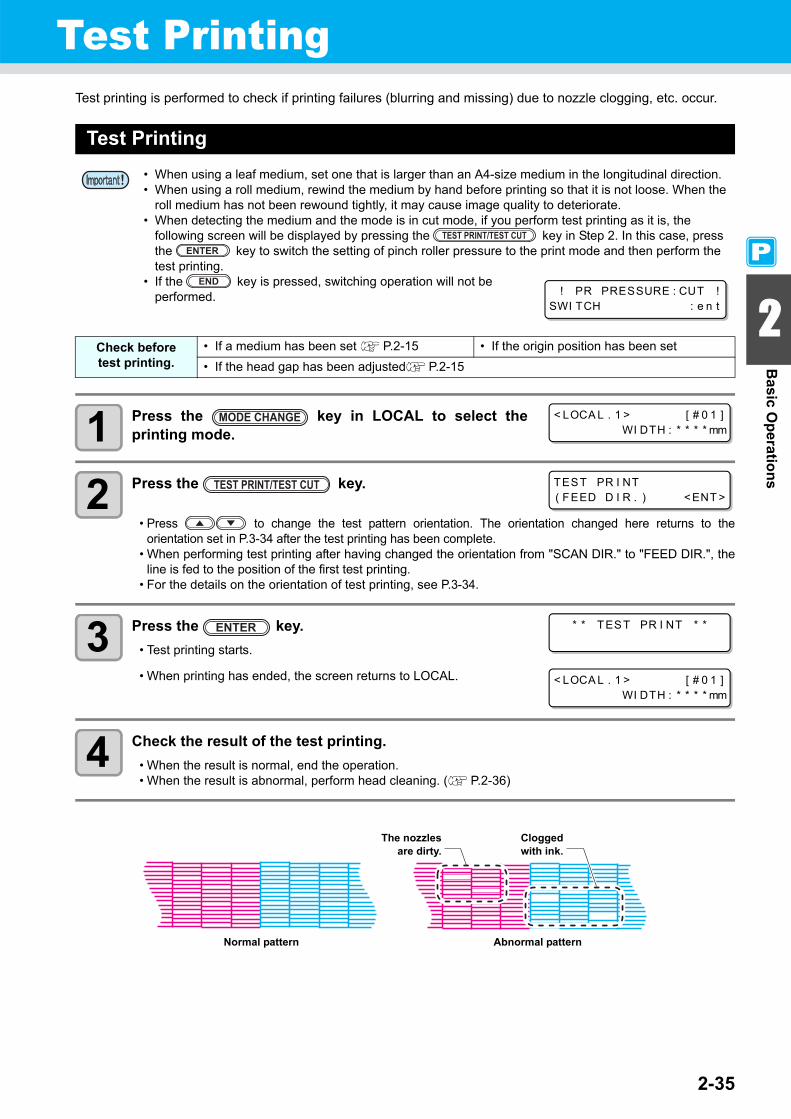
2-35
2
Basic O
perations
Test PrintingTest printing is performed to check if printing failures (blurring and missing) due to nozzle clogging, etc. occur.
Test Printing
1 Press the key in LOCAL to select theprinting mode.
2 Press the key.
• Press to change the test pattern orientation. The orientation changed here returns to theorientation set in P.3-34 after the test printing has been complete.
• When performing test printing after having changed the orientation from "SCAN DIR." to "FEED DIR.", theline is fed to the position of the first test printing.
• For the details on the orientation of test printing, see P.3-34.
3 Press the key.• Test printing starts.
• When printing has ended, the screen returns to LOCAL.
4 Check the result of the test printing.• When the result is normal, end the operation.• When the result is abnormal, perform head cleaning. ( P.2-36)
• When using a leaf medium, set one that is larger than an A4-size medium in the longitudinal direction.• When using a roll medium, rewind the medium by hand before printing so that it is not loose. When the
roll medium has not been rewound tightly, it may cause image quality to deteriorate. • When detecting the medium and the mode is in cut mode, if you perform test printing as it is, the
following screen will be displayed by pressing the key in Step 2. In this case, press the key to switch the setting of pinch roller pressure to the print mode and then perform the test printing.
• If the key is pressed, switching operation will not be performed.
Check beforetest printing.
• If a medium has been set P.2-15 • If the origin position has been set• If the head gap has been adjusted P.2-15
! PR PRESSURE : CUT !SWI TCH : e n t
< LOCA L . 1 > [ # 0 1 ]WI DTH : * * * * mm
TEST PR I NT( FEED D I R . ) < ENT >
* * TEST PR I NT * *
< LOCA L . 1 > [ # 0 1 ]WI DTH : * * * * mm
Abnormal pattern
Cloggedwith ink.
Normal pattern
The nozzlesare dirty.

Test Printing
2-36
Performing Head CleaningHead cleaning can be performed in three ways. Select one according to the result of test printing.
NORMAL : When any line is missingSOFT : When only head wiping is needed (when lines are bent)HARD : When poor image quality cannot be improved even by NORMAL or SOFT cleaning
1 Press the key in LOCAL to select theprinting mode.
2 Press the key.
3 Press to select a type of cleaning.
4 Press the key.• The remaining cleaning time is indicated in the lower part of the
display.• When cleaning has ended, the screen returns to LOCAL.
5 Perform test printing again to check the result.• Repeat the cleaning and test printing until the result becomes normal.
When 600cc cartridge is usedEven when [Ink Level] is displayed, enough ink for head cleaning may remain in the ink pack.When [Ink Level] appears, see "When [Ink Level] is displayed" in the provided manual "When using 600 cc cartridge" and enter the current weight of the 600cc cartridge.
When the remaining ink is not enough for head cleaningWhen the remaining ink is not enough for head cleaning, an error shown on the right appears on the step 3. Replace with a new ink pack, and then perform head cleaning again.
When image quality is not improved even though head cleaning is repeated:• Clean the wiper and ink cap. ( P.6-6)• Wash the nozzle head. ( P.6-11)• See "When Nozzle Clogging Cannot Be Solved" to improve poor image quality. ( P.6-21)
< LOCA L . 1 > [ # 0 1 ]WI DTH : * * * * mm
CL EAN I NGTYPE : NORMA L
CL EAN I NGTYPE : HARD
CL EAN I NG ACT I VE0 0 : 0 0
* * * 6 0 0 c c E r r o r * * *s h o r t a g e o f i n k .
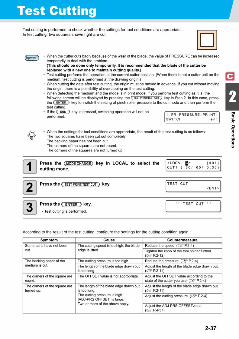
2-37
2
Basic O
perations
Test CuttingTest cutting is performed to check whether the settings for tool conditions are appropriate.In test cutting, two squares shown right are cut.
1 Press the key in LOCAL to select thecutting mode.
2 Press the key.
3 Press the key.• Test cutting is performed.
According to the result of the test cutting, configure the settings for the cutting condition again.
• When the cutter cuts badly because of the wear of the blade, the value of PRESSURE can be increased temporarily to deal with the problem. (This should be done only temporarily. It is recommended that the blade of the cutter be replaced with a new one to maintain cutting quality.)
• Test cutting performs the operation at the current cutter position. (When there is not a cutter unit on the medium, test cutting is performed at the drawing origin.)
• When cutting the data after test cutting, the origin must be moved in advance. If you cut without moving the origin, there is a possibility of overlapping on the test cutting.
• When detecting the medium and the mode is in print mode, if you perform test cutting as it is, the following screen will be displayed by pressing the key in Step 2. In this case, press the key to switch the setting of pinch roller pressure to the cut mode and then perform the test cutting.
• If the key is pressed, switching operation will not be performed.
• When the settings for tool conditions are appropriate, the result of the test cutting is as follows:The two squares have been cut out completely.The backing paper has not been cut.The corners of the squares are not round.The corners of the squares are not turned up.
Symptom Cause CountermeasureSome parts have not been cut.
The cutting speed is too high, the blade edge is lifted.
Reduce the speed. ( P.2-4)Tighten the knob of the tool holder further.( P.2-12)
The backing paper of the medium is cut.
The cutting pressure is too high. Reduce the pressure. ( P.2-4)The length of the blade edge drawn out is too long.
Adjust the length of the blade edge drawn out.( P.2-11)
The corners of the square are round.
The OFFSET value is not appropriate. Adjust the OFFSET value according to the state of the cutter you use. ( P.2-4)
The corners of the square are turned up.
The length of the blade edge drawn out is too long.The cutting pressure is high.[ADJ-PRS OFFSET] is large.Two or more of the above apply.
Adjust the length of the blade edge drawn out.( P.2-11)Adjust the cutting pressure. ( P.2-4)
Adjust the ADJ-PRS OFFSETvalue. ( P.4-37)
! PR PRESSURE : PR I NT !SWI TCH : e n t
< LOCA L . C > [ # 0 1 ]CUT 1 ( 3 0 / 6 0 / 0 . 3 0 )
TEST CUT< ENT >
* * TEST CUT * *

2-38
Preparing for the HeatersChanging the Temperature Settings for the Heaters
The temperature settings for the heaters can be changed and stored in P.3-12 "Changing the TemperatureSettings for the Heaters".Described here is how to change the already set temperature.Set the heater temperature according to the characteristics of the media you use.
• The temperature of the heaters has been set to "OFF" as default.• Appropriate temperature adjustment can be made because the temperature can be adjusted even during printing.• It may take several minutes to tens of minutes for the set temperature to be reached, depending on the ambient
temperature.
1 Press the key in LOCAL.
2 Press the key.
3 Press to set the temperature of each heater.
Heater selection : Select one with .Temperature setting : Set the temperature with .
• The heater starts to get hot. (The [HEAT] lamp lights in orange.)
4 The heating of the heater stops.• When the heater temperature reaches the set temperature, the [HEAT] lamp goes off and the
[CONSTANT] lamp lights in green.
5 Press the key to stop heating.• The screen returns to Local.
• You can register the temperature of the heaters beforehand according to the types of media you use. P.3-2 "Registering All Printing Conditions Together (Type Registration)"
• The temperature set by the operation above is not reflected in the set values of the heaters whose types have been registered. The currently set temperature is not changed until the power is turned OFF or a new temperature is set on the following conditions:
(1) Change the type of the heater.(2) Change the heater temperature according to P.3-12 "Changing the Temperature Settings for the
Heaters".(3) Specify the heater temperature from the PC.
• When the RIP you use has the function of controlling the heater temperature, the temperature can be controlled on the RIP side. (For how to control the temperature, see the instruction manual for the RIP you use.)
• Use this machine at a temperature between 20 to 35°C. The temperature may not reach the set value, depending on the ambient temperature.
PRE PRT POST3 5 ° C 4 0 ° C 5 0 ° C
Screen for checking the heater temperature
4 0 ° C 4 0 ° C 5 0 ° C( OF F OF F OF F )
Temperature set in [HEATER] of the type registration
4 0 ° C 4 0 ° C 5 0 ° C( OF F OF F OF F )
Set temperature: 20 to 50°C

Preparing for the Heaters
2-39
2
Basic O
perations
Reference for Temperature Setting
Checking the Heater Temperature
1 Press on the operation panel.• The current heater temperature is displayed.
2 Press to end the checking.• The screen returns to LOCAL.
Ink type BS* inkMedia type Glossy chloroethylene Tarpaulin FF
Pre-heater setting 35°C 35°C 35°CPrint heater setting 35°C 35°C 35°CPost-heater setting 50°C 50°C 50°C
• Adjust the temperature appropriately according the state of the medium you use.
• When switching the mode to the print mode after cutting data in the cut mode and pressing the key, “OFF” is displayed on each heater temperature. When pressing the key again, the temperature will go up to the set temperature.
PRE PRT POST3 5 ° C 4 0 ° C 5 0 ° C

2-40
Printing DataStarting a Printing Operation
1 Set a medium. ( P.2-15)
2 Check the heater temperature.• Check the CONSTANT lamp lights in [PRE], [PRINT], and
[POST] below the display.
3 Press the key in LOCAL.• The screen changes to REMOTE, and data can be received from the
PC.
4 Transmit data to be printed from the PC.• The pressure is switched automatically in concert with the pinch
roller pressure set in P. 3-6 "Setting for the Pinch Rollers".• The ACTIVE lamp blinks and the printing conditions are displayed.• For the method of data transmission, see the instruction manual for
the output software.
5 Start printing.• The printing speed may change, depending on the width of the set
medium or the position of the print origin even when the same datais printed. This is because of a difference in resolution.
• When using a roll medium, rewind the medium by hand before printing so that it is not loose. When the roll medium has not been rewound tightly, it may cause the image quality to deteriorate.
• When switching the mode to the print mode after cutting data in the cut mode, “OFF” is displayed on each heater temperature. Press the key twice, and then raise the heater temperature up to the set temperature and perform printing.
TEMPERATURE CONTROL !P L EASE WA I T
* REMOTE * 7 2 0 x 7 2 01 6 . B d . V d . x 2 x x . x xm
Resolution: 360/540/720/1440 DPI
Number of passes
Length of the printed medium
Scanning directionUd: Unidirectional Bd: Bidirectional
Data typeVd: Variable dataNd: Normal data
Scanning speedx1: Standard speedx2: Double speed

Printing Data
2-41
2
Basic O
perations
Stopping a Printing OperationPerform the following operation when stopping a printing operation halfway.
1 Press the key during printing.• The printing operation stops.• Interrupt data sending at the PC side during the data is sent from the PC.• Printing restarts from the interrupted data by repressing the key.
Deleting Received Data (Data Clear)When you want to stop printing, delete the already received data.
1 Press the key in LOCAL.
2 Press the key.• The ACTIVE lamp goes off.• The received data is deleted, and the present mode returns to LOCAL.
< LOCA L . 1 > [ # 0 1 ]WI DTH : * * * * mm
DATA CL EAR< ENT >
* * DATA CL EAR * *

2-42
Data CuttingStarting a Cutting Operation
Also when printing data with a pen, follow the procedure below.
1 When the machine is in a REMOTE state, the PC transmits data to be cut.
• The pressure is switched automatically in concert with the pinchroller pressure set in P. 4-3 "Setting for the Pinch Rollers".
• When the machine has received the data, the data starts the cutting automatically.
• When the cutting has been completed, the display appears as the one shown right.
Stopping Cutting in a WhileIf you stop cutting or pen plotting in a while, perform the following operation.
1 Press the key while the machine is operating.• The operation of the machine stops in a while and it enters a local state.• The time it takes for the operation of the machine to stop is different, depending on the data being
processed.When a circle is processed: After the circle has been processed, the operation stops.Other line segments : After they have been processed by the unit of vector, the operation
stops.
Restarting a Cutting Operation
1 Press the key to restart a cutting operation.• The machine enters a REMOTE state, and a cutting operation is restarted.
Functions That Can Be Set after a Cutting Operation Has Been Stopped
Changing the tool condition
"About Tool Conditions during Cutting" of P.2-3
Stopping a cutting operation of the received data
"Stopping a Cutting Operation (Data Clear)" of P.2-43
* REMOTE . C * [ # 0 1 ]CUT 1 ( 3 0 / 6 0 / 0 . 3 0 )

Data Cutting
2-43
2
Basic O
perations
Stopping a Cutting Operation (Data Clear)If you want to stop a cutting operation of the received data, clear the data.
• When clearing the data, the process will not restart even if you press the key.• After clearing the data, switching to the remote mode and receiving another data, new data will be cut.
1 Press the key in LOCAL.
2 Press the key.• The ACTIVE lamp goes out.• The reception buffer is cleared, and the present mode returns to LOCAL.
Removing the Cutter Unit TemporarilyWhen cutting or printing-with-a-pen job is finished, the cutter unit is on the platen.To check the result of cutting (printing-with-a-pen) or to set a new medium, follow the steps below to remove thecutter unit from the platen temporarily.
1 Press the key in LOCAL.
2 Press the key.• The cutter unit moves from on the platen to the left end of the
machine.
• Do not perform the data clearance during the data transmitting.• Even after performing the data clearance, the received data is stored in the reception buffer. You can
specify the data performed data clearance and perform Multiple Cuttings. ( P. 4-46)
DATA CL EAR< ENT >
* * DATA CL EAR * *
CUT HEAD RETRACT< ENT >
P L EASE WA I T

2-44
Cutting a MediumThere are two methods of cutting medium: automatic and manual.
Automatic CuttingAfter printing has been completed, the medium is cut off automatically.
1 When printing has been completed, the medium is cut automatically.
Manual CuttingBy using the keys on the operation panel, you can cut the medium at any position.
1 Press the key in LOCAL.• LOCAL changes to the origin setting mode.• By pressing , feed the medium to the cutting position.
2 Press the key.
3 Press the key.• The medium is cut.• When the cutting has been completed, the current mode returns to LOCAL.
• When cutting a medium, select a cutting method according to the size of the medium. ( P.5-4"Setting a Cut Method")
• When a medium is cut, be careful that the printed side does not touch the floor or the printed side ofother already cut media.
• When you use a take-up device, roll up the cut medium by using the switch of the take-up device.• The set pinch roller ( P.2-17) detects the size of the medium and then determines the cutting method
using it as a reference. If both ends of the medium are away from the pinch roller, note that the mediummay remain uncut.
• In order to activate the automatic cutting function, the setting for it needs to be configured. (Theautomatic cutting function is set to "OFF" as default.)
• The automatic cutting function needs to be set for printer function ( P.3-28) and cut function ( P.4-22) separately.
• When the automatic cutting function is "OFF", perform the operation in "Manual Cutting" described laterto cut a medium.
OR I G I N SET UP0 . 0 - - - -
MED I A CUT< ENT >
MED I A CUT T I NGP L EASE WA I T

This chapter
describes the operation procedures for using the printing function more conveniently andeach setting procedure.
About User Types ....................................... 3-2Registering All Printing Conditions Together (Type Registration) ...................................... 3-2How to Register User Types ....................... 3-2
Setting the Pinch Rollers ........................... 3-5Recommended Setting for the Pinch Roller Pressure ...................................................... 3-5Quantity of Pinch Rollers ............................. 3-5Setting for the Pinch Rollers ........................ 3-6
Setting Media Correction ........................... 3-8Setting Media Correction ............................. 3-8
If the Positions of Dots Shift.................... 3-10Changing the Set Values of the Heaters. 3-12
Changing the Temperature Settings for the Heaters ................................................ 3-12Adjustment to an Appropriate Temperature .............................................. 3-14When the Heater Temperature Does Not Reach the Preset One ............................... 3-15
Setting the Printing Method..................... 3-16Setting of Printing Quality .......................... 3-16Setting a Scanning Direction ..................... 3-18Setting Logical Seek ................................. 3-19
Setting Drying Time .................................. 3-20Setting Priority Order................................ 3-22Setting Automatic Cleaning ..................... 3-24Setting Cleaning during Printing ............. 3-26Other Settings ........................................... 3-27Copying the Set Contents ........................ 3-29Initializing the Settings ............................. 3-30Machine Settings....................................... 3-31
Setting the DEODORIZE FAN ...................3-31Setting the DRYNESS FEED .....................3-32Stamp Setting ............................................3-33Setting the Test Print Arrange ...................3-34When using 600 cc cartridge (firmware Ver.2.10 or older ) ......................3-35When using 600 cc cartridge (firmware Ver.2.20 or later) ........................3-41Change the operation condition of the ambient temperature ..................................3-47
Extension of Ink Expiry Month................. 3-48Switch Setting of Ink Supply Path ........... 3-50
Chapter 3Extended Functions – Printer –

3-2
About User TypesRegistering All Printing Conditions Together (Type Registration)
This machine allows you to register printing conditions in each of the user types (1 to 4).Register a printing condition according to each media that you use in a user type beforehand. When you replaceone medium to another, you can set the optimum printing condition only by changing one user type to another.
Example of Type Registration
How to Register User Types
1 Press the key in LOCAL to select theprinting mode.
2 Press the key.
3 Press the key.
4 Press to select one of the types (1 to 4) and press the key.
5 Select and set each item of "List of Functions to Be Set".• For details on how to set each function, see the reference page contained in "List of Functions to Be Set in
User Types".
Type 1 For Tarpaulin1 Type 3 For FF (Flexible Face)Type 2 For Tarpaulin2 Type 4 Polyvinyl chloride mat
< LOCA L . 1 > [ # 0 1 ]WI DTH : * * * * mm
FUNCT I ONSETUP < ENT >
SETUPSE L ECT : TYPE . 1

3-3
About User Types
3
Extended Functions – Printer –
List of Functions to Be Set in User TypesThis section describes the overview of each function to be set and set values that can be registered in user types.The underlined has been set as default.
Function Name Set Value OverviewPINCH ROLLER( P.3-5)
ENDS HIGH/MIDDLE/LOW Used to set the pinch roller pressure.
INNER HIGH/MIDDLE/LOW/OFF
No. 2 to Used to set the number of the pinch roller atthe left end of the medium.
MEDIA COMP. ( P.3-8) -255 to 0 to 255 Used to print a pattern for correcting a media-feeding rate and correct it.
DROP. POS CORRECT ( P.3-10) -40.0 to 0 to 40.0 Used to adjust the dot position in go andreturn printing.
HEATER ( P.3-12)
SET TEMP. PRE HEATER
OFF/ 20 to 50°C(OFF/ 68 to 122°F)
Used to set heater conditions.
PRINT HEATER
OFF/20 to 50°C(OFF/68 to 122°F)
POST HEATER
OFF/20 to 50°C(OFF/68 to 122°F)
SET TIME STANDBY (NONE/0 to 90 minby the unit of 10 min)
OFF TIME (NONE/0 to 90 minby the unit of 10 min)
PRINT MODE( P.3-16)
DRAFT QUALITY STD/ FAST / FINE Used to set printing quality and a printingdirection.FINE QUALITY STD/ FAST / FINE
SCAN DIRECTION Bi-D / Uni-D
LOGICAL SEEK ON/OFF
INK LAYER ( P.3-27) 1 to 9 Used to set the number of layers to which inkis applied.
DRYING TIME( P.3-20)
SCAN 0.0 to 19.9 sec Used to set the time for ink to dry.
PRINT END 0 to 999 sec
AUTO CUT ( P.3-27) ON/OFF Used to cut the media automatically afterprinting.
PRE-FEED( P.3-27) ON/OFF Used to feed a medium back and forth beforeprinting.When a sticky medium is used, select ON.
COLOR PATTERN ( P.3-27) ON/OFF Used to print a color pattern on the right edgeof a medium.
REFRESH ( P.3-27) LEVEL 0 (Long interval forrefreshing) to 3 (Short intervalfor refreshing)
Used to refresh the print heads duringprinting.
VACUUM ( P.3-27) OFF / STANDARD / WEAK /LittleWEAK / STRONG
Used to set the ability to adsorb a medium.
FEED SPEED LEVEL ( P.3-27) 10 to 100 to 200%10%........6 mm/sec
100%......60 mm/sec200%....120 mm/sec
Used to change the media-feeding speed during printing, etc.

About User Types
3-4
Function Name Set Value OverviewPRIORITY ( P.3-22) INDIVIDUALLY / ALL HOST /
ALL PANELUsed to set the priority order of settings (byhost/panel). Used to set the following items individuallywhen the individual setting is selected.
• Media correction• Heater• Printing method• Ink-laying printing• Drying time• Automatic Cutting• Pre-feed• Color pattern• Refreshing• VACUUM• Feeding speed level
AUTO CLEANING ( P.3-24)
ON INTERVAL 10 to 1,000 to 10,000 mm Used to set the automatic cleaning of the printing heads performed for each printing operation.
TYPE NORMAL / SOFT / HARD
OFF
PRINT. CLEANING ( P.3-26)
ON INTERVAL 10 to 1,000 to 10,000 mm Used to set the automatic cleaning of the printing heads performed during printing.TYPE NORMAL / SOFT / HARD
OFF

3-5
3
Extended Functions – Printer –Setting the Pinch Rollers
Set the pinch roller pressure and the pinch roller numbers according to the medium to be used.
Recommended Setting for the Pinch Roller PressureThe table below shows the recommended pinch roller pressure for printing:
Quantity of Pinch RollersThe following table shows the quantity of the pinch rollers for each model.Check the pinch rollers on your machine for quantity.
Settings Set Value Overview
ENDSHIGH
Set the pressure for the pinch rollers at both ends of the medium according to themedium to be used.MIDDLE
LOW
INNER
HIGHSet the pressure for the pinch rollers other than those at both ends of the mediumaccording to usage.
MIDDLELOWOFF
No. 2 to 7 *1
*1. The number of pinch rollers varies according to the machine type.
Set the number of the leftmost pinch roller according to the size of the medium to beused.
Set pressure UsageENDS : MiddleINNER: Middle For standard operation
ENDS : HighINNER: Low
Use this combination of settings when you want to minimize the traces of pinch rollers on themedium.
• This setting may cause misalignment of the medium depending on themedium type, feeding rate, or medium width.
• When you use the machine under conditions other than the above, the medium may slip out of place during printing.
• Adjust the pinch roller pressure according to the situation.
Model QuantityCJV30-160BS 7 piecesCJV30-130BS 6 piecesCJV30-100BS 4 piecesCJV30-60BS 3 pieces

3-6
Setting for the Pinch RollersThis section describes the setting procedure for CJV30-160BS.For CJV30-130BS/100BS/60BS, the number of pinch rollers set in Step 10 varies.
1 Press the key in LOCAL to select theprinting mode.
2 Press the key.
3 Press the key.
4 Press to select one of the types (1 to 4) and press the key.
5 Press the key.
6 Press to set the pressure for the pinchrollers at both ends of the medium.
• Set value: HIGH/MID./LOW
7 Press to move the cursor to themiddle pinch roller setting.
End pinch roller (left end)
End pinch roller (right end)
Middle pinch rollers
• The figure above shows CJV30-160BS.
PinchRoller
PinchRoller No.
< LOCA L . 1 > [ # 0 1 ]WI DTH : * * * * mm
FUNCT I ONSETUP < ENT >
SETUPSE L ECT : TYPE . 1
ENDS : H I GH [ H_ _ _ _ _H ]I NNER : OF F No . 7 - 1
ENDS : M I D . [ H_ _ _ _ _H ]I NNER : OF F No . 7 - 1
ENDS : M I D . [ H_ _ _ _ _H ]I NNER : OF F No . 7 - 1

Setting the Pinch Rollers
3-7
3
Extended Functions – Printer –
8 Press to set the pressure for the middle pinch rollers.
• Set value: HIGH/MID./LOW/OFF
9 Press to move the cursor to the pinch rollernumber setting.
10 Press to set the number of the pinch roller atthe left end of the medium.
• Set value: 2 to 7
11 Press the key.
12 Press the key several times to end the setting.
Advanced Setting for the Middle Pinch RollersAdvanced setting is available for the middle pinch rollers according to the medium to be used.
1 Perform the operations in Steps 1 to 10 in P.3-6 "Setting for the Pinch Rollers".
2 Press the key.
3 Press to select a pinch roller to set, and press to set the advanced setting.
4 Press the key.
5 Press the key several times to end the setting.
• Pinch roller pressure set here is reflected to the medium in the following condition:When print/cut remotelyWhen detecting the medium next
• If you wish to reflect the set value to the medium currently set, detect the medium again by moving the clamp lever up and down.
• When printing in the local mode such as the dot position correction or medium correction, perform the steps from Step 1 and set the pinch roller pressure again.
ENDS : M I D . [ H_ _ _ _ _H ]I NNER : M I D . No . 7 - 1
ENDS : M I D . [ H_ _ _ _ _H ]I NNER : M I D . No . 7 - 1
ENDS : M I D . [ _ _ _H_ _H ]I NNER : M I D . No . 4 - 1
ENDS : M I D . [ H_ _ _ _ _H ]I NNER : M I D . No . 7 - 1
ENDS : M I D . [ H_ _ _ L _H ]I NNER : M I D . No . 7 - 1

3-8
Setting Media CorrectionIn the following cases, be sure to set medium correction and correct the amount of the medium feeding.
• when replacing the kind of the medium ( P.2-15)• when changing the heater temperature ( P.2-38)• when changing the pinch roller pressure in the pinch roller setting ( P.3-6)
If the correction value is not appropriate, stripes may appear on the printed image, thus resulting in a poorprinting.
Setting Media CorrectionA pattern for media correction is printed and a medium-feeding rate is corrected.
1 Set a medium. ( P.2-15)
2 Press the key in LOCAL to select the printing mode.
3 Press the key.
4 Press the key.
5 Press to select one of the types (1 to 4) and press the key.
• When you have changed the temperature of the heaters, make sure that the [CONSTANT] lamp lights up and that the preset temperature is reached, and then start the correction.
• When printing with a take-up device, set the medium first and then perform media correction.
• Two bands are printed in the correction pattern.• Make adjustment so that an even color density is obtained in the boundary between the two bands.
• When detecting the medium and when the mode is in cut mode, if you correct the medium as it is, the following screen will be displayed by pressing the key in Step 7. In this case, press the
key to switch the setting of pinch roller pressure to the print mode and then print the correction pattern.
• If the key is pressed, switching operation will not be performed.
Second band
First band
Medium-feeding direction
! PR PRESSURE : CUT !SWI TCH : e n t
< LOCA L . 1 > [ # 0 1 ]WI DTH : * * * * mm
FUNCT I ONSETUP < ENT >
SETUPSE L ECT : TYPE . 1

Setting Media Correction
3-9
3
Extended Functions – Printer –
6 Press to select [MEDIA COMP.].
7 Press the key.
8 Press the key to print a correction pattern.
9 Check the correction pattern and enter a correction value.• Press the to enter a correction value.
Enter a correction value in "+" : The boundary between the two bands is widened.Enter a correction value in "-" : The boundary between the two bands is narrowed.
• When you change the correction value by "10", the width of the boundary changes by about 0.1 mm.
10 Press the key twice.• Print a correction pattern again and check it.• When media correction is needed, perform the operation in Step 9 to
make correction.• Press the key several times to end correction.
Correcting Media-feeding during PrintingA media-feeding rate can be corrected even in the remote mode or when image data is printed.
1 Press the key in the remote mode.
2 Press the key.
3 Press to enter a corrected feeding rate.• Corrected feeding rate: -500 to 500• The value entered here is reflected in the corrected feeding rate soon.
4 Press the key.• When you press the key instead of the key, the
value entered here will be invalid.
5 Press the key.• The changed value is registered.• When you press the key instead of the key, the
value entered here will be valid temporarily. (When you performmedia detection again or turn the power OFF, the correction value iscleared.)
[ 1 ]MED I A COMP . < e n t >
[ 1 ] MED I A COMP .PR I NT START : e n t
PR I NT I NGP L EASE WA I T
[ 1 ] MED I A COMP .VA LUE = 0
[ 1 ] MED I A COMP .PR I NT START : e n t
FEED COMPENSAT I ON .0
FEED COMPENSAT I ON .0 > 1
FEED COMPENSAT I ON .SAVE : e n t
* REMOTE . 1 + * [ # 0 1 ]* * . * * mm
This indicates that media correction was made in the remote mode.

3-10
If the Positions of Dots Shift...When the condition for printing (medium thickness/head height/setting of pinch roller pressure/ink type/etc.) hasbeen changed, perform the following operation to correct the ink drop position for bidirectional (Bi) printing andobtain the proper printing result.
Example of a Printed Pattern
1 Set a medium on the machine and set a printing origin. ( P. 2-15, P. 2-33)• In order to print a pattern, a medium that is 500 mm wide and at least 400 mm long is necessary.
2 Press the key in LOCAL to select the printing mode.
3 Press the key.
4 Press the key.
5 Press to select one of the types (1 to 4) and press the key.
6 Press to select [DROP.POScorrect].
7 Press the key.
8 Press the key to start pattern printing.• Multiple test patterns are printed. (The printed patterns are called
Pattern 1, Pattern 2, Pattern 3... in the order of printing.)
• When detecting the medium and when the mode is in cut mode, if you correct the dot position as it is, the following screen will be displayed by pressing the key in Step 7. In this case, press the
key to switch the setting of pinch roller pressure to the print mode and then print the pattern.• If the key is pressed, switching operation will not be
performed. ! PR PRESSURE : CUT !SWI TCH : e n t
The fourth in the + direction from the 0 position is indicated as a straight line.In this case, the dot position correction value is 4.0.
Output direction
< LOCA L . 1 > [ # 0 1 ]WI DTH : * * * * mm
FUNCT I ONSETUP < ENT >
SETUPSE L ECT : TYPE . 1
[ 1 ]DROP . POS c o r r e c t < e n t >
[ 1 ] DROP . POS c o r r e c tPR I NT START : e n t
PR I NT I NGP L EASE WA I T

If the Positions of Dots Shift...
3-11
3
Extended Functions – Printer –
9 Press to correct the dot position of Pattern 1.• Correction value: -40 to 40• Check the test patterns. The position where an outward feeding line
and a return feeding line become one straight line is the correctionvalue.
• When the correction value in not between -40 and 40, adjust theheight of the printing heads and then perform the operations in Step2 and later.
• 2 types of the correction value is available depending on the head height.
10 Press the key.
11 In the same way as in Step 9, correct the dot position in Pattern 2 and subsequentpatterns and press the key.
12 Press the key several times to end the correction.
[ 1 ] DROP . POS c o r r e c ( H )PAT TERN1 = 0 . 0
Displays the current head height.
(H)... High (thick)(L) ... Low (thin)

3-12
Changing the Set Values of the HeatersReference for Temperature Setting
Changing the Temperature Settings for the HeatersHere, each item of "SET TEMP." and "SET TIME" is set.
1 Press the key in LOCAL to select theprinting mode.
2 Press the key.
3 Press the key.
4 Press to select one of the types (1 to 4) and press the key.
Ink type BS* inkMedia type Glossy chloroethylene Tarpaulin FF
Pre-heater setting 35°C 35°C 35°CPrint heater setting 35°C 35°C 35°CPost-heater setting 50°C 50°C 50°C
• Adjust the temperature appropriately according to the state of the medium you use.
Temperature setting (SET TEMP.) Used to change the set temperature of the pre-heater, print heater, andpost-heater inside the platen.
Time setting *1(SET TIME)
*1. The time set here is valid only when the printing is completed. The value when print & cut operation or cutting operation is completed is deferent depending on the application software (RasterLinkPro4 or later, FineCut7 or later) you use.
STANDBY
Used to set the time it takes until the temperature of the heaters falls toreach the preheat temperature after printing has been complete.Set value:NONE, 0 to 90 min (by the unit of 10 min)• The preheat temperature has been preset and cannot be changed.• If the machine receives data with the preheat temperature reached, the
heaters automatically raise their temperature up to the set temperature, and then the machine starts printing.
• When the set value has been set to "NONE", the heaters do not lower their temperature to the preheat one.
OFF TIME
The heaters are turned off in the following cases:• When printing is not performed longer than the preset time in the standby
mode• When printing is not performed longer than the preset time after printing has
been completed with "NONE" being selected for the set value of "STANDBY"
Set value:NONE, 0 to 90 min (by the unit of 10 min)If the machine receives data with the heaters turned off, the heaters areautomatically turned on to raise their temperatures up to the preset levelsand then the machine starts printing.• When "NONE" is selected for the set value, the heaters are not turned off.• When "0 min" is set for the set value, the heaters are turned off after printing
has been complete.
< LOCA L . 1 > [ # 0 1 ]WI DTH : * * * * mm
FUNCT I ONSETUP < ENT >
SETUPSE L ECT : TYPE . 1

3-13
Changing the Set Values of the Heaters
3
Extended Functions – Printer –
5 Press to select [HEATER].
6 Press the key twice.• The heater temperature setting screen appears.
7 Press to set the temperature of each heater.
Heater selection: Select one with .Temperature setting: Set the temperature with .
8 Press the key.
9 Press to select [SET TIME].
10 Press the key.
11 Press to set time.Item selection:Select one with .Time setting: Set time with .
12 Press the key.
13 Press the key several times to end the setting.• The screen returns to LOCAL.
• Use this machine at a temperature between 20 to 35°C. The temperature may not reach the set value, depending on the ambient temperature conditions.
[ 1 ]HEATER < e n t >
PRE PRT POST2 5 ° C 2 5 ° C 3 5 ° C
PRE PRT POST3 5 ° C 4 0 ° C 5 0 ° C
Set temperature: 20 to 50°C
[ 1 ] HEATERSET TEMP . < e n t >
[ 1 ] HEATERSET T I ME < e n t >
STANDBY : OF F T I ME1 0m i n : NONE
STANDBY : OF F T I ME1 0m i n : NONE
Set value: NONE, 0 to 90 min(by the unit of 10 min)

3-14
Adjustment to an Appropriate TemperatureThis section describes how to adjust the temperature of the heaters to an appropriate one.Because the heater temperature should be different, depending on the types of media, ambient temperature,etc., set an appropriate temperature for each medium. For non-coated media or media on which ink is slow todry, increase the heater temperature so that the ink fixing and drying characteristics can be improved.Check the items in the following method to set an appropriate temperature.
Wait until the CONSTANT lamp lights up.
Set the temperature of the heaters. ( P.3-12)
Make media correction. ( P.3-8)
YesNo
Is the medium wrinkled?
Test printing
Does the medium stick to the platen?
Does beading occur?
End
Lower the heater
temperature.
Raise the heater
temperature.
Move the medium back and forth with the [ ] and [ ] keys.
Initially, set a higher temperature.
No
No
Yes
Yes

Changing the Set Values of the Heaters
3-15
3
Extended Functions – Printer –
When the Heater Temperature Does Not Reach the Preset OneWhen the heater temperature is too low or the ink capacity (ink limit) is too small, printing failures, such asbeading and banding, may occur.
Beading is a phenomenon that adjacent dots attract and stick to one another. Beading causes speckled patternsor stripes along printing passes (banding).
Example of BeadingThe area in the vicinity of 100% magenta looks fine. Generally, the area in the vicinity of 70-100% single color iseasily affected by the unevenness of a media feeding rate. The print shown here, free from unevenness of colorin the vicinity of 100% magenta area, shows that media-feeding has been adjusted appropriately.
In the blue area (100% magenta + 100% cyan), however, speckled patterns and banding have occurred. Thisbanding is a result of beading. When the heater temperature is low or the ink capacity (ink limit) of a medium issmall, the first dot does not solidify before the second dot lands on the medium. As a result, dots stick to oneanother and unevenness or banding occurs.In order to prevent beading, it is recommended to raise the heater temperature to increase the ink capacity (inklimit) of the medium, to adjust the ink volume per dot for the medium, to increase the number of printing passesand decrease the ink amount for one shot, and/or to gain time by scan wait. Change the medium if none of the above-mentioned measures works to prevent beading.
Fine looking print
Print with banding

3-16
Setting the Printing MethodIn the printing method setting, the following items are set:• Printing quality (DRAFT) : Printing quality in the DRAFT mode (resolution in the scanning direction: 540 dpi) is set.• Printing quality (FINE) : Printing quality in the FINE mode (resolution in the scanning direction: 720 dpi) is set.• Scanning direction : A printing direction is set.• Logical seek : ON/OFF of Logical seek is set.
Setting of Printing Quality
1 Press the key in LOCAL to select the printing mode.
2 Press the key.
3 Press the key.
4 Press to select one of the types (1 to 4) and press the key.
5 Press to select [PRINT MODE].
6 Press the key.
7 Select items to set.(1) Press to select [DRAFT QUALITY] or [FINE QUALITY].
([DRAFT QUALITY] is selected here.)(2) Press .
8 Press to select a printing quality.• Set value:STD./ FAST/ FINE• When ending the setting here, press the key to proceed to Step 11.
Set Item Set Value OverviewDRAFT QUALITY
STD. / FAST / FINE Used to select an image quality for printing.FINE QUALITY
< LOCA L . 1 > [ # 0 1 ]WI DTH : * * * * mm
FUNCT I ONSETUP < ENT >
SETUPSE L ECT : TYPE . 1
[ 1 ]PR I NT MODE < e n t >
[ 1 ] PR I NT MODEDRAF T QUA L I TY < e n t >
[ 1 ] PR I NT MODEDRAF T q u a l i t y : STD .

3-17
Setting the Printing Method
3
Extended Functions – Printer –
9 When changing the details of printing quality in each resolution, press to select a resolution.
(1) Press to select a resolution.(2) Press .
• Set value:540 x 720, 540 x 900, 540 x 1,080 dpi (when DRAFT is selected)720 x 540, 720 x 720, 720 x 1,080, 720 x 1,440 dpi (when FINE is selected)
10 Select the number of passes and a printing speed.(1) Select the number of passes with and press .(2) Select a printing speed (Fast or Standard) with .(3) Press .
• The set value for the number of passes is different, depending on the content of ink setting or theresolution selected in Step 8. See "Combination of Factors That Can Be Set" to select the number ofpasses.
11 Press the key several times to end the setting.
Combination of Factors That Can Be SetWhen changing the details of printing quality in Steps 9 and 10 of "Setting of Printing Quality”, see the table belowto set printing quality.
DRAFT quality FINE qualityResolution
(dpi)4 colors 6 colors Resolution
(dpi)4 colors 6 colors
Pass Speed Pass Speed Pass Speed Pass Speed540 x 720
dpi4 Fast/Standard 8 Fast/Standard 720 x 540 6 Fast/Standard 6 Fast/Standard8 16 12 12
16 32 24 24540 x 900
dpi10 Fast/Standard 10 Fast/Standard 720 x 720 4 Fast/Standard 8 Fast/Standard20 20 8 1640 40 16 32
540 x 1,080dpi
6 Fast/Standard 12 Fast/Standard 720 x 1,080 6 Fast/Standard 12 Fast/Standard12 24 12 2424 48 24 48
720 x 1,440 8 Fast/Standard 16 Fast/Standard16 3232 64
[ 1 ] DRAF T QUA L I TY5 4 0 x 7 2 0 < e n t >
[ 1 ] DRAF T QUA L I TYPASS = 8 : SCAN=H i SPEED

3-18
Setting a Scanning Direction
1 Perform the operations in P.3-16 Steps 1 to 6.
2 Press to select [SCAN DIRECTION].
3 Press the key.
4 Press to select a scanning direction.• Set value : Bi-D, Uni-D
5 Press the key.
6 Press the key several times to end the setting.
Set Value Overview
Bi-D Printing is performed in both outward and return directions of the printer unit.Select this when you want to print in a shorter period of time.
Uni-D Printing is performed only in the outward direction of the printer unit.Select this when you want to print finer.
[ 1 ] PR I NT MODEDRAF T QUA L I TY < e n t >
[ 1 ] PR I NT MODESCAN D I RECT I ON < e n t >
[ 1 ] PR I NT MODES c a nD I RECT I ON : B i - D
[ 1 ] PR I NT MODES c a nD I RECT I ON : Un i - D
[ 1 ] PR I NT MODESCAN D I RECT I ON < e n t >

Setting the Printing Method
3-19
3
Extended Functions – Printer –
Setting Logical Seek
1 Perform the operations in P.3-16 Steps 1 to 6.
2 Press to select [LOGICAL SEEK].
3 Press the key.
4 Press to select ON/OFF.
5 Press the key.
6 Press the key several times to end the setting.
Set Value Overview
ON The printer unit moves according to the size of the data during printing.Select this when you want to print in a shorter period of time.
OFF The printer unit moves from the right edge to the left edge of a medium, regardless of the size ofthe data. When you use a medium on which ink is hard to dry, you can have a longer drying time.
Unidirectional printing Bidirectional printing
Unidirectional printing Bidirectional printing Movement of the heads when Logical seek is OFF
Movement of the heads when Logical seek is ON
[ 1 ] PR I NT MODEDRAF T QUA L I TY < e n t >
[ 1 ] PR I NT MODELOG I CA L SEEK < e n t >
[ 1 ] PR I NT MODELOG I CA L SEEK : ON
[ 1 ] PR I NT MODELOG I CA L SEEK : OF F
[ 1 ] PR I NT MODELOG I CA L SEEK < e n t >

3-20
Setting Drying TimeThe following items for ink drying time are set.
1 Press the key in LOCAL to select theprinting mode.
2 Press the key.
3 Press the key.
4 Press to select one of the types (1 to 4) and press the key.
5 Press to select [DRYING TIME].
6 Press the key.
7 Press to set drying time.Item selection:Select one with .Time setting:Set time with .
Set Item Set Value Overview
SCAN 0.0 to 19.9 secInk drying time for each scanning is set.(During bidirectional printing, the machine stops for a certain period of timespecified for each of the outward and return scanning.)
PRINT END 0 to 8 hours Ink drying time after printing has been complete is set.(The next printing is not performed until the set drying time passes.)
< LOCA L . 1 > [ # 0 1 ]WI DTH : * * * * mm
FUNCT I ONSETUP < ENT >
SETUPSE L ECT : TYPE . 1
[ 1 ]DRY I NG T I ME < e n t >
SCAN : PR I NT END0 . 0 s : 0 h 0 0m0 0 s
SCAN : PR I NT END0 . 0 s : 0 h 0 0m0 0 s
Scanning:0.0 to 19.9 sec
After printing:0 to 8 hours

Setting Drying Time
3-21
3
Extended Functions – Printer –
8 Press the key.
9 Press the key several times to end the setting.
[ 1 ]DRY I NG T I ME < e n t >

3-22
Setting Priority OrderIt is determined which is prioritized for printing, the setting by the machine (panel) or the setting by the PC (host).
Items to be selected :Media correction / Heater / Printing method / Ink-laying printing / Drying time / Automatic cutting / Pre-feed / Color pattern / Refreshing / Adsorption / Feeding speed level
1 Press the key in LOCAL to select theprinting mode.
2 Press the key.
3 Press the key.
4 Press to select one of the types (1 to 4) and press the key.
5 Press to select [PRIORITY].
6 Press the key.
7 Press to select one of the set values.
• Set value :INDIVIDUALLY/ ALL HOST / ALL PANEL• When selecting [INDIVIDUALLY], proceed to Step 8. When selecting [ALL HOST] or [ALL PANEL], press
the key and proceed to Step 12.
8 Press the key.• The setting screen of media correction appears.
9 Press to select "HOST" or "PANEL".
10 Press the key.• You can move between items also by pressing . However, unless you press the key,
the set value is not determined.
Set Value Overview
INDIVIDUALLY It is determined which is prioritized for the items below this table, the setting by this machine(panel) or the setting by the PC (host).
ALL HOST The setting by the PC (host) for the items below this table is prioritized.ALL PANEL The setting by this machine (panel) for the items below this table is prioritized.
< LOCA L . 1 > [ # 0 1 ]WI DTH : * * * * mm
FUNCT I ONSETUP < ENT >
SETUPSE L ECT : TYPE . 1
[ 1 ]PR I OR I TY < e n t >
[ 1 ] PR I OR I TYSETUP : AL L HOST
[ 1 ] PR I OR I TYSETUP : I ND I V I DUA L L Y
[ 1 ] PR I OR I TYMED I A COMP . : HOST
[ 1 ] PR I OR I TYMED I A COMP . : PANE L

Setting Priority Order
3-23
3
Extended Functions – Printer –
11 Perform the same operations as in Steps 9 and 10 to set other items.
12 Press the key several times to end the setting.
• Even with the setting by the host being prioritized, the items set by the panel become effective if they have not been specified by the host.

3-24
Setting Automatic CleaningYou can set items so that the head cleaning is automatically performed when printing has been completed for theset length.When printing has been completed, the machine measures the length of a medium printed after the previoushead cleaning and performs the cleaning automatically if necessary. The machine can perform a stable printing operation with its heads always kept clean. Cleaning is performed before the first printing after the machine has started. Then subsequent cleaning isperformed according to the length (by the unit of meter) of a printed medium.
When the operation interval is 1,000 mm (example)
1 Press the key in LOCAL to select theprinting mode.
2 Press the key.
3 Press the key.
4 Press to select one of the types (1 to 4) and press the key.
5 Press to select [AUTO CLEANING].
6 Press the key.
7 Press to select ON.• When selecting OFF, proceed to Step 9.
Set Item Set Value OverviewINTERVAL 10 to 1,000 mm Interval between each automatic cleaning operation (print length)
TYPE NORMAL / SOFT /HARD A cleaning type is selected.
Print length: 1.6 m cleaning (3rd time)
Print length: 0.0 m cleaning (1st time)
Print length: 0.8 m no cleaning
Print length: 1.6 m cleaning (2nd time)
Print length: 0.8 m no cleaning
When five images that are 80 cm long are printed in sequence, cleaning is performed before the 1st, 3rd, and 5th images are printed.
< LOCA L . 1 > [ # 0 1 ]WI DTH : * * * * mm
FUNCT I ONSETUP < ENT >
SETUPSE L ECT : TYPE . 1
[ 1 ]AUTO CL EAN I NG < e n t >
[ 1 ] AUTO CL EAN I NGSETUP : OF F
[ 1 ] AUTO CL EAN I NGSETUP : ON

Setting Automatic Cleaning
3-25
3
Extended Functions – Printer –
8 Press the key.
9 Press to set a cleaning interval and a cleaning type.
Item selection : Select one with .Setting of an interval and type :
Set an interval and type with .
10 Press the key.
11 Press the key several times to end the setting.
• This function does not operate when ink near-end occurs. See P.1-14 "Changing an Ink Cartridge" to solve ink near-end.
• Depending on the state of the heads, etc., the image quality deterioration may not be improved even with this function performed. In this case, contact our service office or the distributor in your region.
I NTERVA L : TYPE1 0 0 0mm : NORMA L
I NTERVA L : TYPE1 0 0 0mm : NORMA L
INTERVAL:10 to 10,000 mm
TYPE: NORMALSOFTHARD

3-26
Setting Cleaning during PrintingIt is set whether head cleaning is performed automatically during printing.In cleaning during printing, a cleaning interval is set according to the length of a printed medium. Printing is interrupted each time a medium is printed for the set length, and head cleaning is performedautomatically during the interval.
1 Press the key in LOCAL to select theprinting mode.
2 Press the key.
3 Press the key.
4 Press to select one of the types (1 to 4) and press the key.
5 Press to select [Print. CLEANING].
6 Press the key.
7 Press to select ON.• When selecting OFF, proceed to Step 10.
8 Press the key.
9 Press to set a cleaning interval and a cleaning type.
Item selection : Select one with .Setting of an interval and type:
Set an interval and type with .
10 Press the key.• Press the key several times to end the setting.
Set Item Set Value OverviewINTERVAL 10 to 1,000 mm Interval between each cleaning operation (print length)
TYPE NORMAL / SOFT /HARD A cleaning type is selected.
• This function does not operate when ink near-end occurs. See P.1-14 "Changing an Ink Cartridge" to solve the ink near-end.
• Depending on the state of the heads, etc., the image quality deterioration may not be improved even with this function performed. In this case, contact our service office or the distributor in your region.
< LOCA L . 1 > [ # 0 1 ]WI DTH : * * * * mm
FUNCT I ONSETUP < ENT >
SETUPSE L ECT : TYPE . 1
[ 1 ]P r i n t . CL EAN I NG< e n t >
[ 1 ] P r i n t . CL EAN I NGSETUP : OF F
[ 1 ] P r i n t . CL EAN I NGSETUP : ON
I NTERVA L : TYPE1 0 0 0mm : NORMA L
I NTERVA L : TYPE1 0 0 0mm : NORMA L
INTERVAL:10 to 10,000 mm
TYPE: NORMALSOFTHARD

3-27
3
Extended Functions – Printer –Other Settings
Change the settings according to the types of use.
1 Press the key in LOCAL to select theprinting mode.
2 Press the key.
3 Press the key.
4 Press to select one of the types (1 to 4) and press the key.
5 Press to select an item to set.• See "List of Settings". (P.3-28)
6 Press the key.
7 Press to select a set value.• See "List of Settings". (P.3-28)
8 Press the key.
9 Press the key several times to end the setting.
• The set value is retained even when the power is turned “OFF”.
< LOCA L . 1 > [ # 0 1 ]WI DTH : * * * * mm
FUNCT I ONSETUP < ENT >
SETUPSE L ECT : TYPE . 1

Other Settings
3-28
List of SettingsThe underlined has been set as default.
Function Name Overview Set Value
PINCH ROLLERSetting the pinch roller pressure and the pinch roller numbers according to the medium to be used.
See P.3-5.
MEDIA COMP. A medium-feeding rate is corrected. See P.3-8.
DROP. POS CORRECT Setting used when the thickness of the medium, head height, or ink type is changed. See P.3-10.
HEATERThe heater temperature is set.
See P.3-12.The standby time and OFF time of the heaters are set.
PRINT MODEPrinting quality is set.
See P.3-16.A scanning direction is set.Logical seek is set.
INK LAYER The number of ink layers is set. Once to nine times
DRYING TIMEInk drying time for each scanning is set.
See P.3-20.Ink drying time after printing has been complete is set.
AUTO CUT Whether a medium is automatically cut after printing is set. ON/OFF
PRE-FEED Whether a medium is fed back and forth before printing is set. ON/OFF
COLOR PATTERN It is set whether a color pattern is printed on the right edge of a medium.*1
*1. When ON is set, maximum printing width becomes 18mm narrower.When cutting only with RasterLinkPro4 or later, maximum cutting width also becomes 18mm narrower. If it affects the data layout,set to OFF.
ON/OFF
REFRESH The refreshing level of the heads is set. 0 to 3
VACUUM The ability to adsorb a medium is set. STORONG / STANDARD /LittleWEAK / WEAK /OFF
FEED SPEED The speed at which a medium is fed during printing, etc. is set. 10 to 100 to 200%
PRIORITY The prioritized setting (by the host or the panel) is determined.
INDIVIDUALLY / ALL HOST /ALL PANEL
AUTO CLEANING Automatic head cleaning conducted for each printing operation is set. See P.3-24.
PRINT. CLEANING Automatic head cleaning conducted during printing is set. See P.3-26.

3-29
3
Extended Functions – Printer –Copying the Set Contents
The contents you set can be copied to other type.
1 Press the key in LOCAL to select theprinting mode.
2 Press the key.
3 Press the key.
4 Press to select one of the types (1 to 4) and press the key.
5 Press to select [SETUP COPY].
6 Press the key.
7 Press to select the type to copy (1 to 4 or ALL).• If “ALL” is selected, the set contents of all types are same.
8 Press the key.
9 Press the key.
10 Press the key several times to end the resetting.
< LOCA L . 1 > [ # 0 1 ]WI DTH : * * * * mm
FUNCT I ONSETUP < ENT >
SETUPSE L ECT : TYPE . 1
[ 1 ]SETUP COPY < e n t >
[ 1 ] SETUP COPYTYPE . 1 - > TYPE . 2
[ 1 ] SETUP COPYTYPE . 1 - > TYPE . 3
COPY : e n tTYPE . 1 - > TYPE . 3

3-30
Initializing the SettingsThe already configured settings are initialized. (Resetting)The setting items of the selected type are reset.
1 Press the key in LOCAL to select theprinting mode.
2 Press the key.
3 Press the key.
4 Press to select one of the types (1 to 4) and press the key.
5 Press to select [SETUP RESET].
6 Press the key.
7 Press the key.• The already configured settings are initialized.
8 Press the key several times to end the resetting.
< LOCA L . 1 > [ # 0 1 ]WI DTH : * * * * mm
FUNCT I ONSETUP < ENT >
SETUPSE L ECT : TYPE . 1
[ 1 ]SETUP RESET < e n t >
[ 1 ] SETUP RESETRESET : e n t

3-31
3
Extended Functions – Printer –Machine Settings
Common settings are functions for using this machine easily.The following items can be set in Machine settings.
Setting the DEODORIZE FANThe exhaust fan operates during printing. After printing has been complete, it operates according to the setting of"Stop timer".
The following two items can be set for the exhaust fan.• STOP TIME : The time until the exhaust fan stops after printing has been completed is set.• RENEW : When this is set to "ON", the exhaust fan can operate while printing is not performed.
1 Press the key in LOCAL to select theprinting mode.
2 Press the key.
3 Press to select [MACHINE SETUP].
4 Press the key twice.
5 Press to select an item to set.STOP TIME : The time until the exhaust fan stops after printing has been completed is set.RENEW : Select this when you want to operate the exhaust fan.
Item Set Value*1
*1. The underlined has been set as default.
Overview
DEODRIZE SETUP*2
*2. The exhaust fan is optional.
STOP TIME
OFF / 10 to 120 to 240 min/CONTINUE
The time until the rotation of the exhaust fan stops after printing has been completed is set. ( P. 3-31)
RENEW ON/OFF The present operating state of the exhaust fan is switched. ( P. 3-31)
DRYNESS FEED ON/OFF It is set whether a medium is fed for it to be dried after printing has been completed. ( P. 3-32)
STAMP SETUP ON/OFF The setting for the output date and printing conditions to be output after printing has been completed is configured. ( P. 3-33)
Waste Ink Warning ON/OFF It is set whether the confirmation message of the waste ink tank is displayed. ( P. 6-41)
Test PRT. Arrange FEED DIR./SCAN DIR.
The orientation of test patterns when test printing has been repeated is set. ( P. 3-34)
600cc Cartridge *3
*3. It is not displayed when the 600cc cartridge is not set in the ink slot.
Setting the weight of an eco-case. ( P. 3-34)
CART.PRIORITY INK LEVELEXP. DATE
Setting a cartridge to be used first for double cartridge automatic change function.
ENV. TEMP. *4
*4. This function is available for the firmware Ver.2.30 and later.
Not wait ARR.Wait arrival
Sets the operation when an error indicating that the ambient temperature is out of the usable temperature range occurs. ( P. 3-47)
• The exhaust fan is an option contained in the drying exhaust unit. • When this machine is equipped with a drying fan, the fan operates in cooperation with the settings
configured here.
< LOCA L . 1 > [ # 0 1 ]WI DTH : * * * * mm
FUNCT I ONSETUP < ENT >
FUNCT I ONMACH I NE SETUP < ENT >
DEODR I ZE FANSTOP T I ME < e n t >

3-32
6 Press the key.
7 Press to select a set value.STOP TIME : 0 to 240 sec or continuous operationRENEW : When you operate the exhaust fan, select "ON". When you stop the fan, select "OFF".
8 Press the key.• Press the key several times to end the setting.
Setting the DRYNESS FEEDIt is set whether a medium is fed for it to be dried after printing has been completed.
1 Press the key in LOCAL to select theprinting mode.
2 Press the key.
3 Press to select [MACHINE SETUP].
4 Press the key.
5 Press to select [DRYNESS FEED].
6 Press the key.
7 Press to select ON/OFF.
8 Press the key.
9 Press the key several times to end the setting.
< LOCA L . 1 > [ # 0 1 ]WI DTH : * * * * mm
FUNCT I ONSETUP < ENT >
FUNCT I ONMACH I NE SETUP < ENT >
MACH I NE SETUPDEODR I ZE FAN < e n t >
MACH I NE SETUPDRYNESS FEED < e n t >
DRYNESS FEEDSETUP : ON

3-33
Machine Settings
3
Extended Functions – Printer –
Stamp SettingIt is set whether information, such as printing conditions and a printing date, is output after printing has beencompleted.
1 Press the key in LOCAL to select theprinting mode.
2 Press the key.
3 Press to select [MACHINE SETUP].
4 Press the key.
5 Press to select [STAMP SETUP].
6 Press the key.
7 Press to select ON/OFF.
8 Press the key.• Press the key several times to end the setting.
Output Example
< LOCA L . 1 > [ # 0 1 ]WI DTH : * * * * mm
FUNCT I ONSETUP < ENT >
FUNCT I ONMACH I NE SETUP < ENT >
MACH I NE SETUPDEODR I ZE FAN < e n t >
MACH I NE SETUPSTAMP SETUP < e n t >
STAMP SETUPSTAMP : OF F

3-34
Setting the Test Print ArrangeThe orientation of test patterns that are printed when test printing is repeated can be set.
1 Press the key in LOCAL to select theprinting mode.
2 Press the key.
3 Press to select [MACHINE SETUP].
4 Press the key.
5 Press to select [TestPRT.Arrange].
6 Press the key.
7 Press to select a set value.FEED DIR. : Oriented in the media-feeding direction (rear) (default setting)SCAN DIR. : Oriented in the media-scanning direction (lateral)
8 Press the key.• Press the key several times to end the setting.
Media-feeding direction
: When the set value is "FEED DIR.": When the set value is "SCAN DIR."
< LOCA L . 1 > [ # 0 1 ]WI DTH : * * * * mm
FUNCT I ONSETUP < ENT >
FUNCT I ONMACH I NE SETUP < ENT >
MACH I NE SETUPDEODR I ZE FAN < e n t >
MACH I NE SETUPT e s t PRT . A r r a n g e < e n t >
T e s t P r i n t A r r a n g eSETUP : FEED D I R .

3-35
Machine Settings
3
Extended Functions – Printer –
When using 600 cc cartridge (firmware Ver.2.10 or older )
Requisite for the 600 cc cartridge
Mounting/removing 600 cc ink packFor mounting/removing the 600 cc ink pack, refer to the label adhered on the eco case.
Precaution for using 600 cc cartridgeBe sure to put the ink pack and the ink chip in the eco case for setting the 600 cc cartridge on the ink station.
Registering weight of eco caseRegister the eco case weight on this machine to calculate the remaining ink quantity from the weight of the 600cc cartridge.
Eco CaseThe 600 cc ink pack and the attached ink chip are put in the eco case and used.This is referred to as "600 cc cartridge" in this manual.600 cc Ink Pack
Ink Chip *1
*1.Attached to the 600cc ink pack.
Scale
To calculate the remaining ink quantity, input the weight of the eco case and the600 cc cartridge into this machine. Use a scale for weight measuring. (To managethe accurate remaining ink quantity, prepare the scale that can weigh in one gramunit.)
• This machine cannot judge whether the 600 cc ink pack is in the eco case or not. When using the 600 cc cartridge, be sure to attach the ink pack.
• Setting an eco case without ink chip on the machine will break this machine. Be sure to attach the ink chip to the eco case before use.
Register the weight of the eco case in the following cases.• For using the 600 cc cartridge for the first time • When the case weight is changed by replacing the eco case.
• The weight of each eco case slightly differs respectively. To control accurate ink quantity, be sure to register the weight of each eco case.

3-36
When using 600 cc cartridge for the first timeWhen the 600 cc cartridge is set in the slot of the ink station, the weight registration function of the eco caseautomatically starts.
1 Measure the weight of the eco case.• Measure the weight of the eco case only in advance.• If the 600 cc ink pack is in the eco case, remove the 600 cc ink pack and then perform measurement.
2 Set the 600 cc cartridge in the ink station.• Mount the 600 cc ink pack and the ink chip on the eco case, and set
it to the ink slot.• The input screen for the weight of the eco case will be displayed.
3 Pressing the keys input the weight of the eco case.
• Press the keys to move to another digit.• Press the keys to input the weight.
4 Press the key.• For setting 600 cc cartridges in multiple slots, repeat the procedures in Step 2 and 3.• After all registration is completed, the device will return to the status before the weight registration function
was initiated.
CART . S l o t . . 3 . . . . .c a s e we i g h t = 3 0 0 g
CART . S l o t . . 3 . . . . .c a s e we i g h t = 3 5 5 g

3-37
Machine Settings
3
Extended Functions – Printer –
When the eco case weight is changedWhen the case weight is changed by replacing the eco case, register the weight of the eco case in the followingprocedures.
1 Press the key in LOCAL to select theprinting mode.
2 Press the key.
3 Select [MACHINE SETUP] by pressing the keys.
4 Press the key.
5 Select [600cc Cartridge] by pressing the keys.
• When the 600 cc cartridge is not set, “ 600 cc Cartridge” will not be displayed.
• It is recommended to measure the weight of the eco case inadvance and then perform the procedure from the Step 5.
6 Press the key.
7 Select [Slot] by pressing the keys.• The selected slot is highlighted.
8 Press the key.• The weight input screen is displayed.
9 Pressing the keys input the weight of the eco case.
• Press the keys to move to another digit.• Press the keys to input the weight.
10 Press the key.
• The slot selection screen is displayed again.• When you want to register the weight of another slot continuously,
repeat the Step 6 to select a slot.
11 Press the key several times to end the setting.
< LOCA L . 1 > [ # 0 1 ]WI DTH : * * * * mm
FUNCT I ONSETUP < ENT >
FUNCT I ONMACH I NE SETUP < ENT >
MACH I NE SETUPDEODOR I ZE FAN < e n t >
MACH I NE SETUP6 0 0 c c Ca r t r i d g e < e n t >
CART . S l o t s e l e c t1 . 3 4 . . 7 .
CART . S l o t s e l e c t1 . 3 4 . . 7 .
CART . S l o t . . 3 . . . . .c a s e we i g h t = 3 0 0 g
CART . S l o t . . . 4 . . . .c a s e we i g h t = 3 5 5 g
CART . S l o t s e l e c t1 . 3 4 . . 7 .

3-38
When [Ink Level] is displayedIf quantity of the remaining 600 cc ink becomes low, a warning [Ink Level] appears.To use the ink remaining in the ink pack, input the 600 cc cartridge weight displaying the warning.
1 If [Ink level] is displayed, remove the 600cc cartridgeand measure the weight of the 600cc cartridge.
• Be sure to measure the weight of the eco case including the 600 cc ink pack.
2 Reinsert the 600cc cartridge.
3 Press the key.
4 Pressing the keys input the weight of the 600cc cartridge.
• Press the keys to move to another digit.• Press the keys to input the weight.
5 Press the key.
6 Press the key.• Return to the local mode or the remote mode.
• This function is only available for the 600 cc cartridge displaying [Ink Level] warning.• This function is available for resetting the 600cc cartridge on the local mode or remote mode (in the
standby status or in the printing status). • This machine calculates the available quantity of remaining ink from the weight of the 600 cc cartridge
input in this machine. Accurately weigh the 600 cc cartridge down to 1 gram unit.
• If available ink remains, [Ink Level] warning disappears and [NEAR END] appears.• If [Ink Level] warning is displayed after inputting the weight, available ink is used up. Immediately
replace the ink pack with new one.• The ink in the ink pack cannot be completely used up.
To prevent ink supply trouble, the ink remains about 30 cc in the pack.(To use 600 cc of ink, 630 cc or more ink contains in the pack.)
• You can input the weight of the same 600 cc cartridge up to two times (Three times for the 600 cc cartridge used for initial filling). (It depends on the machine or the environment used.)If [Ink Level] warning occurs after that, replace the ink pack.
• If you want to use the currently-used ink continuously because the ink remains much in the ink pack, repeat the weight input every time [Ink Level] warning occurs.
• To input a larger value than the actual weight of the 600 cc cartridge will cause a dot missing by false control of the remaining ink.
< LOCA L . 1 > [ # 0 1 ]I n k L e v e l - - C - - - - -
I n k L e v e l S e t . . C . . . . .E x e c < > Ca n c e l
I n k L e v e l S e t . . C . . . . .[ 1 ] 0 5 5 5 g
Displays the number of inputting the weight for the same 600 cc cartridge .
I n k L e v e l S e t . . C . . . . .0 5 5 5 g OK ? : e n t

3-39
Machine Settings
3
Extended Functions – Printer –
● When an error occurs in the Step 6
This function stores the calculated quantity of remaining ink in the ink chip of the 600cc cartridge.If the 600cc cartridge is removed or there is a problem on the contact of thisdevice and the ink chip, the data storage in the ink chip cannot be performed.In this case, the message on the right will be displayed.If the message is displayed, reinsert the 600cc cartridge and follow theprocedures from the Step 2 again.
Inputting weight of the cartridge after initial ink fillingWhen the initial ink charging ( P. 6-18) was finished after [DISCHARGE & WASH], the screen to input theweight of the 600cc cartridge is displayed.
1 When ink filling is completed, the following screen isdisplayed.
2 Remove the 600cc cartridge and measure the weight.• Be sure to measure the weight of the eco case including the 600 cc ink pack.
3 Reinsert the 600cc cartridge.
4 Pressing the keys input the weight of the 600cc cartridge.
• Press the keys to move to another digit.• Press the keys to input the weight.
5 Press the key.
6 Press the key.• If there is a 600 cc cartridge, which the quantity of remaining ink is not set, the screen will return to the
Step 1.Repeat the procedures from the Step 1 to 6 for all the 600cc cartridges set in this machine.
• When the setting for the quantity of the remaining ink of all the 600cc cartridges is completed, return to thelocal mode.
• This machine calculates the available quantity of remaining ink from the weight of the 600 cc cartridge input in this machine. Accurately weigh the 600 cc cartridge down to 1 gram unit.
• To input a larger value than the actual weight of the 600 cc cartridge will cause a dot missing by false control of the remaining ink.
* * * 6 0 0 c c E r r o r * * *P r e s e r v a t i o n f a i l u r e
I n k L e v e l S e t . . C . . . . .0 4 0 0 g
I n k L e v e l S e t . . C . . . . .0 5 5 5 g
I n k L e v e l S e t . . C . . . . .0 5 5 5 g OK ? : e n t

3-40
● When an error occurs in the Step 6
This function stores the calculated quantity of remaining ink in the ink chip of the 600cc cartridge.If the 600cc cartridge is removed or there is a problem on the contact of thisdevice and the ink chip, the data storage in the ink chip cannot be performed.In this case, the message on the right will be displayed.If the message is displayed, reinsert the 600cc cartridge and follow theprocedures from the Step 3 again.
Error when performing maintenance functionWhen performing the maintenance function such as the head cleaning or the ink filling for the 600 cc cartridge,selected functions can be performed if the quantity of remaining ink is enough to execute the function, even if theink near end occurs.If the quantity of remaining ink is not enough, a message on the right appears,and selected maintenance function is not performed.
* * * 6 0 0 c c E r r o r * * *P r e s e r v a t i o n f a i l u r e
* * * 6 0 0 c c E r r o r * * *S h o r t a g e o f i n k .

3-41
Machine Settings
3
Extended Functions – Printer –
When using 600 cc cartridge (firmware Ver.2.20 or later)
Requisite for the 600 cc cartridge
Mounting/removing 600 cc ink packFor mounting/removing the 600 cc ink pack, refer to the label adhered on the eco case.
Precaution for using 600 cc cartridgeBe sure to put the ink pack and the ink chip in the eco case for setting the 600 cc cartridge on the ink station.
Registering weight of eco caseRegister the eco case weight on this machine to calculate the remaining ink quantity from the weight of the 600cc cartridge.
Eco CaseThe 600 cc ink pack and the attached ink chip are put in the eco case and used.This is referred to as "600 cc cartridge" in this manual.600 cc Ink Pack
Ink Chip *1
*1.Attached to the 600cc ink pack.
Scale
To calculate the remaining ink quantity, input the weight of the eco case and the600 cc cartridge into this machine. Use a scale for weight measuring. (To managethe accurate remaining ink quantity, prepare the scale that can weigh in one gramunit.)
• This machine cannot judge whether the 600 cc ink pack is in the eco case or not. When using the 600 cc cartridge, be sure to attach the ink pack.
• Setting an eco case without ink chip on the machine will break this machine. Be sure to attach the ink chip to the eco case before use.
Register the weight of the eco case in the following cases.• For using the 600 cc cartridge for the first time • When the case weight is changed by replacing the eco case.
• The weight of each eco case slightly differs respectively. To control accurate ink quantity, be sure to register the weight of each eco case.
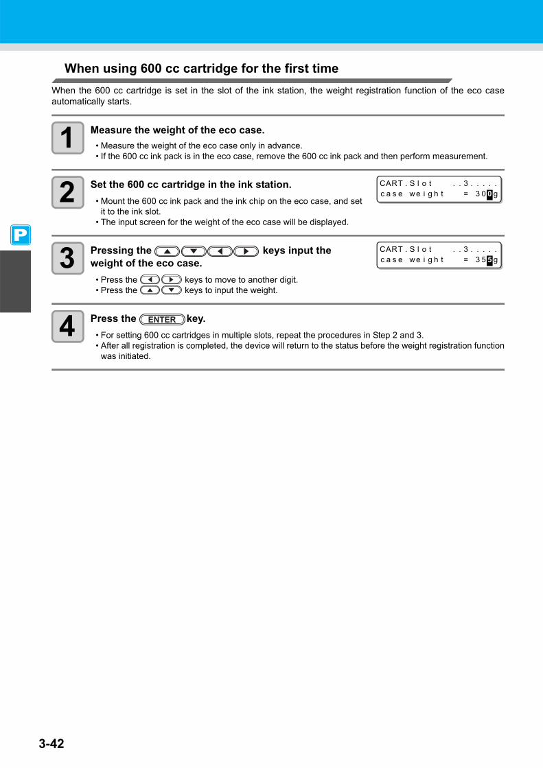
3-42
When using 600 cc cartridge for the first timeWhen the 600 cc cartridge is set in the slot of the ink station, the weight registration function of the eco caseautomatically starts.
1 Measure the weight of the eco case.• Measure the weight of the eco case only in advance.• If the 600 cc ink pack is in the eco case, remove the 600 cc ink pack and then perform measurement.
2 Set the 600 cc cartridge in the ink station.• Mount the 600 cc ink pack and the ink chip on the eco case, and set
it to the ink slot.• The input screen for the weight of the eco case will be displayed.
3 Pressing the keys input the weight of the eco case.
• Press the keys to move to another digit.• Press the keys to input the weight.
4 Press the key.• For setting 600 cc cartridges in multiple slots, repeat the procedures in Step 2 and 3.• After all registration is completed, the device will return to the status before the weight registration function
was initiated.
CART . S l o t . . 3 . . . . .c a s e we i g h t = 3 0 0 g
CART . S l o t . . 3 . . . . .c a s e we i g h t = 3 5 5 g

3-43
Machine Settings
3
Extended Functions – Printer –
When the eco case weight is changedWhen the case weight is changed by replacing the eco case, register the weight of the eco case in the followingprocedures.
1 Press the key in LOCAL to select theprinting mode.
2 Press the key.
3 Select [MACHINE SETUP] by pressing the keys.
4 Press the key.
5 Select [600cc Cartridge] by pressing the keys.
• When the 600 cc cartridge is not set, “ 600 cc Cartridge” will not be displayed.
• It is recommended to measure the weight of the eco case inadvance and then perform the procedure from the Step 5.
6 Press the key.
7 Select [Slot] by pressing the keys.• The selected slot is highlighted.
8 Press the key.• The weight input screen is displayed.
9 Pressing the keys input the weight of the eco case.
• Press the keys to move to another digit.• Press the keys to input the weight.
10 Press the key.
• The slot selection screen is displayed again.• When you want to register the weight of another slot continuously,
repeat the Step 6 to select a slot.
11 Press the key several times to end the setting.
< LOCA L . 1 > [ # 0 1 ]WI DTH : * * * * mm
FUNCT I ONSETUP < ENT >
FUNCT I ONMACH I NE SETUP < ENT >
MACH I NE SETUPDEODOR I ZE FAN < e n t >
MACH I NE SETUP6 0 0 c c Ca r t r i d g e < e n t >
CART . S l o t s e l e c t1 . 3 4 . . 7 .
CART . S l o t s e l e c t1 . 3 4 . . 7 .
CART . S l o t . . 3 . . . . .c a s e we i g h t = 3 0 0 g
CART . S l o t . . . 4 . . . .c a s e we i g h t = 3 5 5 g
CART . S l o t s e l e c t1 . 3 4 . . 7 .

3-44
When [Ink Level] is displayedWhen quantity of the remaining 600 cc ink becomes low, a warning [Ink Level] appears.Enter the weight of the cartridge with the Ink Level Set function.
● Using Ink Level Set function
1 If [Ink level] is displayed, remove the 600cccartridge and measure the weight of the 600cccartridge.
• Be sure to measure the weight of the eco case including the600 cc ink pack.
2 Reset the 600 cc cartridge.
3 Press the key.
4 Pressing the keys input the weight of the 600cc cartridge.
• Press the keys to move to another digit.• Press the keys to input the weight.
5 Press the key.
• This machine recalculates usable amount of remaining ink by entering the weight of the 600 cc cartridge.
• Ink Level Set function starts by resetting the 600 cc cartridge indicating [Ink Level] warning in the local mode or remote mode (during waiting or printing).
• Weight the cartridge exactly down to the gram. Entering a larger weight than the actual one may cause Nozzle Drop Out.
• Use the “E” display as a guide for replacing the ink pack.
• If ink remains much in the ink pack even when “E” is displayed, proceed to the Step 2 and the subsequent steps.
• Ink in the ink pack cannot be completely used up. To prevent ink supply errors, about 30 cc of ink must remain in the ink pack.
< LOCA L . 1 > MMCCYYKKI n k L e v e l - - L - - - E -
Displays the cartridge causing [Ink Level] warning.Upper line: Ink color being setLower line: Cartridge condition
“ - ”No error“L” Ink Level Low“E” Ink Level End
I n k L e v e l S e t . . C . . . . .E x e c < > Ca n c e l
I n k L e v e l S e t . . C . . . . .[ 1 ] 0 5 5 5 g
Displays the set number of times of weight to the cartridge being operated.
I n k L e v e l S e t . . C . . . . .0 5 5 5 g OK ? : e n t

3-45
Machine Settings
3
Extended Functions – Printer –
6 Press the key.• Usable amount of remaining ink is recalculated. • The contents displayed differ depending on the amount of remaining ink.
(1)When ink still remains
• Return to the local mode or the remote mode.• [Ink Level] warning disappears and the state of the 600 cc cartridge
that Ink Level Set function was performed changes to [INK NEAREND] warning.
• [INK NEAR END] warning can be checked on the guidance function.( P. 5-14)
(2)When no ink remains
• A message for replacing the ink pack is displayed.• Press the key to return to the local mode or the remote
mode.• [Ink Level] warning is still displayed and the state of the 600 cc
cartridge that Ink Level Set function was performed changes to [INKEND] warning.
• [INK END] warning can be checked on the guidance function. ( P. 5-14)
● When an error occur in the Step 6
This function stores the calculated quantity of remaining ink in the ink chip of the 600cc cartridge.If the 600cc cartridge is removed or there is a problem on the contact of thisdevice and the ink chip, the data storage in the ink chip cannot be performed.In this case, the message on the right will be displayed.If the message is displayed, reinsert the 600cc cartridge and follow theprocedures from the Step 2 again.
• Once a message for replacing the ink pack appears, immediately replace the target ink pack with a new one. (Usable ink has been used up.)
• Ink in the ink pack cannot be completely used up. To prevent ink supply errors, about 30 cc of ink must remain in the ink pack. (Before shipping, more than 630 cc of ink is filled in the ink pack to use 600 cc.)
< LOCA L . 1 > [ # 0 1 ]
I n k L e v e l S e t . . C . . . . .Re p l a c e i n k p a c k : e n t
< LOCA L . 1 > MMCCYYKKI n k L e v e l - - E - - - - -
Changes the display from [L] to [E].
* * * 6 0 0 c c E r r o r * * *P r e s e r v a t i o n f a i l u r e

3-46
Inputting weight of the cartridge after initial ink fillingWhen the initial ink charging ( P. 6-18) was finished after [DISCHARGE & WASH], the screen to input theweight of the 600cc cartridge is displayed.
1 When ink filling is completed, the following screen isdisplayed.
2 Remove the 600cc cartridge and measure the weight.• Be sure to measure the weight of the eco case including the 600 cc ink pack.
3 Reset the 600 cc cartridge.
4 Pressing the keys input the weight of the 600cc cartridge.
• Press the keys to move to another digit.• Press the keys to input the weight.
5 Press the key.
6 Press the key.• If there is a 600 cc cartridge, which the quantity of remaining ink is not set, the screen will return to the
Step 1.Repeat the procedures from the Step 1 to 6 for all the 600cc cartridges set in this machine.
• When the setting for the quantity of the remaining ink of all the 600cc cartridges is completed, return to thelocal mode.
● When an error occur in the Step 6
This function stores the calculated quantity of remaining ink in the ink chip of the 600cc cartridge.If the 600cc cartridge is removed or there is a problem on the contact of thisdevice and the ink chip, the data storage in the ink chip cannot be performed.In this case, the message on the right will be displayed.If the message is displayed, reinsert the 600cc cartridge and follow theprocedures from the Step 3 again.
Error when performing maintenance functionWhen performing the maintenance function such as the head cleaning or the ink filling for the 600 cc cartridge,selected functions can be performed if the quantity of remaining ink is enough to execute the function, even if theink near end occurs.If the quantity of remaining ink is not enough, a message on the right appears,and selected maintenance function is not performed.
• This machine recalculates usable amount of remaining ink by entering the weight of the 600 cc cartridge.
• Weigh the cartridge exactly down to the gram. Entering a larger weight than the actual one may cause dot missing.
I n k L e v e l S e t . . C . . . . .0 4 0 0 g
I n k L e v e l S e t . . C . . . . .0 5 5 5 g
I n k L e v e l S e t . . C . . . . .0 5 5 5 g OK ? : e n t
* * * 6 0 0 c c E r r o r * * *P r e s e r v a t i o n f a i l u r e
* * * 6 0 0 c c E r r o r * * *S h o r t a g e o f i n k .

Machine Settings
3-47
3
Extended Functions – Printer –
Change the operation condition of the ambient temperatureIf you print in the status that the temperature of the place in which the machine has installed (ambienttemperature) is out of the usable temperature range, ink discharging defect or changing color may occur, and itadversely affects the printing quality.Here, select the operation if the ambient temperature is out of the usable temperature range when printing.
1 Press the key in LOCAL to select theprinting mode.
2 Press the key.
3 Press to select [MACHINE SETUP].
4 Press the key.
5 Press to select [ENV.TEMP.].
6 Press the key.
7 Press to select a set value.Not wait ARR. : The error message is displayed for a moment, and printing starts.Wait arrival : After the error message is displayed, wait until the ambient temperature reaches the
proper value. Then, printing starts.
8 Press the key.• Press the key several times to end the setting.
• For the details of the usable temperature range, refer to P. 8-4 “Allowable temperature”.• If the ambient temperature is out of the usable temperature range at the start of printing, the error
message below is displayed to inform you of it.
* * * * ERROR 1 2 0 * * * *ENV I RONMENT TEMP ( LO )
* * * * ERROR 1 2 1 * * * *ENV I RONMENT TEMP ( H I )
< LOCA L . 1 > [ # 0 1 ]WI DTH : * * * * mm
FUNCT I ONSETUP < ENT >
FUNCT I ONMACH I NE SETUP < ENT >
MACH I NE SETUPDEODR I ZE FAN < e n t >
MACH I NE SETUPENV . TEMP . < e n t >
MACH I NE SETUPSE L : No t wa i t ARR .

3-48
Extension of Ink Expiry MonthInk expiry month can be extended for six months from the expired month. When used without extension, inkbecomes unusable after two months of the expiry month.
Extension of Ink Expiry MonthThe following setting or confirmation screen appears when the power of this machine is turned on, or whenexpired ink cartridge is set.
1 When a screen shown on the right appears, go to thenext step.
2 Press the to select [YES].• When the ink expiry month is not extended, select [NO]. In this
case, the ink will be disabled after two months of the expirymonth.
3 Press the key.• Ink expiry month is extended.
When a cartridge extended the expiry month is setWhen a cartridge extended the expiry month is set and the power is turned on, or when a cartridge extended theexpiry month is set to this machine, the following screen appears.
• An ink cartridge that is once set [YES] for extension cannot be changed the setting.• To extend multiple inks’ expiry month at a time, set the expired ink cartridges, and then set the
extension.• Extension of ink expiry month may lower the print image quality or print quality such as color difference
or banding. Please understand them when extending ink expiry month.• When initial filling, the ink expired more than two months ago cannot be used.
• When extended six months (six months from the ink expired month) have passed, a message “COMPLETELY EXPIRED” appears and the ink becomes unusable. Immediately replace the ink cartridge with a new one.
• If ink expiry month is extended, the cartridge LED blinks in green while supplying ink from the extended cartridge.
• To check expired ink, press the key while displaying the screens above alternately.
EXTEND EXP I RE DATE ?YES < >NO
NOT RECOMMENDED ! !YES < >NO
alternately displayed
EXP I RE DATE EXTENDEDPRESS [ ENT ]
EXP I RED I NK I N USEPRESS [ ENT ]
NOT RECOMMENDED ! !PRESS [ ENT ]
Press the keyalternately displayed

Extension of Ink Expiry Month
3-49
3
Extended Functions – Printer –
When an ink expiry month is extendedExample: If expiry month of your ink cartridge is February 2009.
• When the expiry month is not extended
• When the expiry month is extended (When extended at the time of )
February March April May or later
Printable continuously Not printable continuously Not printable (Unusable)
A message "Expiration:2MONTH" or "COMPLETELY EXPIRED" appears on the display, and the cartridge lamp lights in red.
A message "Expiration:1MONTH" appears on the display, and the cartridge lamp blinks in red.
A message "Expiration" appears.
February March April May or later September
Printable continuously Not printable continuously Printable continuously Not printable
(Unusable)
Printable continuously Not printable continuously
Not printable (Unusable) Printable continuously Not printable
(Unusable)
A message "COMPLETELY EXPIRED" appears.
Even if extended at any time from April to August, it is extended for six months from the expiry month

3-50
Switch Setting of Ink Supply PathFor the ink supply, condition of the ink cartridge to be used first by the double-cartridge automatic switchingfunction can be selected.
1 Press the key in LOCAL to select theprinting mode.
2 Press the key.
3 Select [MACHINE SETUP] by pressing the keys.
4 Press the key.
5 Select [CART.PRIORITY] by pressing the keys.
6 Press the key.
7 Select the condition of ink to be used first by pressing the keys.
INK LEVEL : Low ink cartridge is used firstEXP. DATE : Close-to-date ink cartridge is used first
8 Press the key.
9 Press the key several times to end.
• When expired ink cartridge is set, the expired cartridge is used first regardless of the setting below.• When the optional bulk ink system (MBIS1) is used and the MBIS1 is set in both slots, the setting below
is effective.• When both an ink cartridge and the bulk ink system (MBIS1) are set in the supply paths of the same
color, see the next page.
< LOCA L . 1 > [ # 0 1 ]WI DTH : * * * * mm
FUNCT I ONSETUP < ENT >
FUNCT I ONMACH I NE SETUP < ENT >
MACH I NE SETUPCART . PR I OR I TY < e n t >
CART . PR I OR I TYSE L ECT : I NK L EVE L

Switch Setting of Ink Supply Path
3-51
3
Extended Functions – Printer –
When both ink cartridge and MBIS1 are usedWhen both an ink cartridge and the optional bulk ink system (MBIS1) are set in the supply paths of the samecolor, you can select the ink to be used first.
1 Press the key in LOCAL or REMOTE of theprinting mode.
2 Press the key.
3 Press the key to set the supply path and the ink to be used first.
Select the supply path : Press the key.Select the ink to be used first : Press the key.
4 Press the key.• It enters in the LOCAL or the REMOTE mode.
• Usually, when both an ink cartridge and the bulk ink system (MBIS1) are set in the supply path of the same color, the ink in the bulk ink system (MBIS1) is used first.
• If supply path does not have both ink cartridge and the bulk ink system (MBIS1), this function cannot be set.
• Pull out the ink cartridge selected on this function or turn the power on again to disable the setting.
BS 2 - I NK MMCCYYKKREMA I N 3 4 5 6 7 8 9 9
BUL K / CART SE L ECT- B B B
Displays the currently supplying ink.B : Bulk ink system (MBIS1)C : Ink cartridge- : Only one type is set
BUL K / CART SE L ECT- C B B

3-52

This chapter
describes the operation procedures for using the cutting function more conveniently andeach setting procedure.
Setting the Pinch Rollers ........................... 4-2Recommended Setting for the Pinch Roller Pressure and Number of Pinch Rollers ....... 4-2Quantity of Pinch Rollers ............................. 4-2Setting for the Pinch Rollers ........................ 4-3
Cutting out Data with Register Marks ....... 4-5Flow of Cutting Data with Register Marks ... 4-5Entering Register Mark Detection Mode ..... 4-5Notes on Inputting Data with Register Marks .......................................................... 4-6Setting Register Mark Detection ............... 4-11Method of Detecting Register Marks ......... 4-15When Cutting Failed .................................. 4-17
Setting Automatic Cutting........................ 4-22Dividing and Cutting................................. 4-23
Setting the Dividing and Cutting Function . 4-23Cutting Data by Using the Dividing and Cutting Function ........................................ 4-25
Cutting with a Dotted Line ....................... 4-26
Changing the Order of Cutting ................ 4-28Setting the SORTING ................................4-29Procedure for SORTING ............................4-31
Cutting out Data without Register Marks 4-32Setting the P/C ORIGIN OFFSET ..............4-32Setting the P/C SCALE ADJUST ...............4-34
Other Settings ........................................... 4-36Copying the Setting Contents.................. 4-40Initializing the Settings ............................. 4-41Cutting Samples........................................ 4-42Cutting a Medium into Multiple Pieces with a Certain Length................................ 4-44Perform Multiple Cuttings ........................ 4-46Setting the Step Size................................. 4-48Other Convenient Functions.................... 4-49
Medium Feeding ........................................4-49How to turn the heater OFF in the cutting mode ..........................................................4-50
Chapter 4Extended Functions – Cutting –

4-2
Setting the Pinch RollersSet the pinch roller pressure and the pinch roller numbers according to the medium to be used.
Recommended Setting for the Pinch Roller Pressure and Number of Pinch RollersThe table below shows the recommended pinch roller pressure for cutting:
Quantity of Pinch RollersThe following table shows the quantity of pinch rollers for each model.Check the pinch rollers on your machine for quantity.
Settings Set Value Overview
ENDSHIGH
Set the pressure for the pinch rollers at both ends of the medium according to themedium to be used.MIDDLE
LOW
INNER
HIGH
Set the pressure for the pinch rollers other than those at both ends of the mediumaccording to usage.
MIDDLELOWOFF
No. 2 to 7 *1
*1. The number of pinch rollers varies according to the machine type.
Set the number of the leftmost pinch roller according to the size of the medium to beused.
Set pressure UsageENDS: HighINNER: High For standard operation
ENDS: HighINNER: Low
Use this combination of settings when you want the streaks made by the pinch rollers on themedium to be unnoticeable.
• This setting may cause misalignment of the medium depending on themedium type, feeding rate, or medium width.
Medium width Required pinch rollersLess than 600 mm Both ends only600 to 1,300 mm Both ends + 1 middle pinch roller1,300 mm or more Both ends + 2 middle pinch rollers
• When you use the machine under conditions other than the above, the medium may slip out of place during cutting.
• Adjust the pinch roller pressure according to the situation.
Model QuantityCJV30-160BS 7 piecesCJV30-130BS 6 piecesCJV30-100BS 4 piecesCJV30-60BS 3 pieces
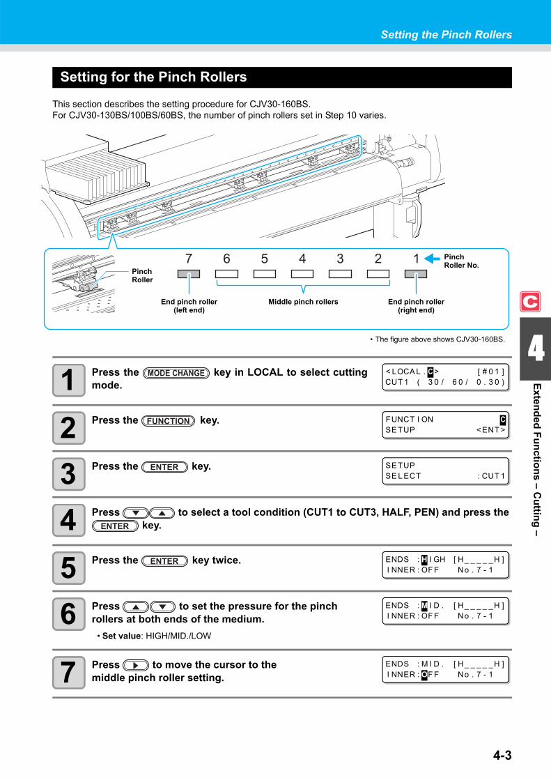
4-3
Setting the Pinch Rollers
4
Extended Functions – Cutting –
Setting for the Pinch Rollers
This section describes the setting procedure for CJV30-160BS.For CJV30-130BS/100BS/60BS, the number of pinch rollers set in Step 10 varies.
1 Press the key in LOCAL to select cuttingmode.
2 Press the key.
3 Press the key.
4 Press to select a tool condition (CUT1 to CUT3, HALF, PEN) and press the key.
5 Press the key twice.
6 Press to set the pressure for the pinch rollers at both ends of the medium.
• Set value: HIGH/MID./LOW
7 Press to move the cursor to themiddle pinch roller setting.
End pinch roller (left end)
End pinch roller (right end)
Middle pinch rollers
• The figure above shows CJV30-160BS.
PinchRoller
PinchRoller No.
< LOCA L . C > [ # 0 1 ]CUT 1 ( 3 0 / 6 0 / 0 . 3 0 )
FUNCT I ON CSETUP < ENT >
SETUPSE L ECT : CUT 1
ENDS : H I GH [ H_ _ _ _ _H ]I NNER : OF F No . 7 - 1
ENDS : M I D . [ H_ _ _ _ _H ]I NNER : OF F No . 7 - 1
ENDS : M I D . [ H_ _ _ _ _H ]I NNER : OF F No . 7 - 1

Setting the Pinch Rollers
4-4
8 Press to set the pressure for the middle pinch rollers.
• Set value: HIGH/MID./LOW/OFF
9 Press to move the cursor to the pinch rollernumber setting.
10 Press to set the number of the pinch roller atthe left end of the medium.
• Set value: 2 to 7
11 Press the key.
12 Press the key several times to end the setting.
Advanced Setting for the Middle Pinch RollersAdvanced setting is available for the middle pinch rollers.
1 Perform the operations in Steps 1 to 10 in P. 4-3 "Setting for the Pinch Rollers".
2 Press the key.
3 Press to select a pinch roller to set, and press to set the advanced setting.
4 Press the key.
5 Press the key several times to end the setting.
• The pinch roller pressure set here is reflected to the medium under the following conditions:When performing print/cut remotelyWhen detecting the medium next
• If you want to reflect the set value to the current medium, move the clamp lever up and down to detect the medium again.
ENDS : M I D . [ H_ _ _ _ _H ]I NNER : M I D . No . 7 - 1
ENDS : M I D . [ H_ _ _ _ _H ]I NNER : M I D . No . 7 - 1
ENDS : M I D . [ _ _ _H_ _H ]I NNER : M I D . No . 4 - 1
ENDS : M I D . [ H_ _ _ _ _H ]I NNER : M I D . No . 3 - 1
ENDS : M I D . [ H_ _ _ L _H ]I NNER : M I D . No . 3 - 1

4-5
4
Extended Functions – Cutting –
Cutting out Data with Register MarksIf you create register marks on an output image, the cutter unit detects these marks and cuts the image outautomatically following these marks. This helps you to make stickers, etc.This section describes how to cut the printed medium.Refer to P.4-10 for the combined operation of print & cut.
There are following two types of register marks.
Flow of Cutting Data with Register Marks
Entering Register Mark Detection Mode
1 Press the key in LOCAL.• The machine enters the register mark detection mode.
• Use the TP4 when performing trapezium correction to correct the uneven medium-feeding rate caused by the difference in the diameter between the right and left grid rollers. If the trapezium correction is to be omitted, there is no need to set the TP4. In that case, however, cutting distortion will increase.
• When the registration detection is set to OFF, the machine doesn't enter registration mode. ( P.4-11)• If this key is pressed while various settings are being configured, the input value may be canceled or the
active set item may be returned to the previous set item.
TP1
TP2
TP3
TP4
TP1
TP2
TP3
TP4
Register mark: Type 1 Register mark: Type 2
Add register marks on the image with which you want to make a sticker, etc., and then print the image with register marks on a medium.
Set the printed medium in CJV30BS.
Send the cut-target image from the computer for cutting.
There are some conditions for creating the register marks.See pages P.4-6 through P.4-10.
Set it referring to P.2-15.
In case it is not successfully cut,•Confirm the response of the register mark sensor. ( P.4-17)
•Confirm the position of the Light Pointer.( P.4-20)
•Adjust the sensitivity of the register mark sensor. ( P.4-21)

4-6
Notes on Inputting Data with Register MarksThere are some limitations on preparing data with register marks.In order to make full use of this function, read the following instructions carefully and prepare data with registermarks properly.
Size of the Register MarksRefer to "The Size of a Register Mark Suited for the Distance between the Marks" ( P.4-8) for the relationship between the data and the length of one side of a register mark.
The Area Where Register Marks and Designs Can Be Arranged• The TP1 starting position must be at least 20 mm away from the front end of the medium.• The TP2 end position must be at least 30 mm away from the rear end of the medium.
Register mark: Type 1
Register mark: Type 2
• The register mark described here is intended to detect the medium skew and the lengths along the X and Y axis. It is not a mark for trimming.
0.3~1.0mm
4~40mm
Design layoutavailable area
Effective cut area(Normal)
Effective cut area(Expand)
Pinch roller
30 mm or more
X: Between 50 to 3,000 mm
20 mm or more
Y: 50 mm or more
Design layoutavailable area
Effective cut area(Normal)
Effective cut area(Expand)
Pinch roller
30 mm + (Mark length/2) or more
X: Between 50 to 3,000 mm
20mm + (Mark length/2) or more
Y: 50 mm or more
Keep the marks away from the pinch rollers.

4-7
Cutting out Data with Register Marks
4
Extended Functions – Cutting –
No-printing Area around the Register MarksAn area around a register mark (from the mark origin to the mark size area) is a non-printing area.There must be no data printed or stain in this area.Otherwise, a wrong origin may be detected or a mark read error can occur.
Example of Cause of Wrong Detection 1There is a line outside the register marks
Example of Cause of Wrong Detection 2The distance between register marks (TP2 and TP1 or TP4 and TP2) is smaller than the mark length (for Type 2)
• If a wrong mark origin is detected, the cutting will be performed in the wrong area.
Mark size
Register mark: Type 1 Register mark: Type 2
No-printing area Register mark
Mark Origin
No-printing areaRegister markMark Origin
No-printing area
Mark Origin
Detected wrong mark origin
Space larger thanthe mark length Space larger than
the mark length
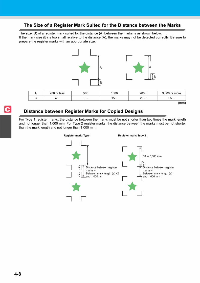
4-8
The Size of a Register Mark Suited for the Distance between the MarksThe size (B) of a register mark suited for the distance (A) between the marks is as shown below.If the mark size (B) is too small relative to the distance (A), the marks may not be detected correctly. Be sure toprepare the register marks with an appropriate size.
(mm)
Distance between Register Marks for Copied DesignsFor Type 1 register marks, the distance between the marks must be not shorter than two times the mark lengthand not longer than 1,000 mm. For Type 2 register marks, the distance between the marks must be not shorterthan the mark length and not longer than 1,000 mm.
A 200 or less 500 1000 2000 3,000 or moreB 4 ~ 8 ~ 15 ~ 25 ~ 35 ~
Register mark: Type Register mark: Type 2
Distance between register marks =Between mark length (a) x2and 1,000 mm
Distance between register marks =Between mark length (a)and 1,000 mm
50 to 3,000 mm

4-9
Cutting out Data with Register Marks
4
Extended Functions – Cutting –
The Recommended Size of the Area Defined with a Set of Four Register MarksIt is recommended that the size of the area defined with a set of four register marks is in the range of A4 size (210mm x 297 mm) to A3 size (297 mm x 420 mm).If you follow this recommendation, you can minimize wasteful spaces and arrange the designs efficiently.
Color of MarkThe mark must be printed in black against the white background.The register mark will not be detected correctly if the background is not white or the mark is not black.
Mark BlurredIf the mark is blurred, a wrong mark origin can be detected, thus resulting in deviated cutting.
A4 size to A3 size
OK NG
OKOK NGNG

4-10
Notes on Register Mark DetectionObserve the following precautions on register mark detection.
• When you retry medium detection, medium skew correction, scale correction between register marks, and theposition of the origin are cleared.
• Once the cutter unit detects marks, it will set the origin at the location of TP1.If you change the position of the origin to a different location using the jog keys, the origin at the new location willsupersede the origin at TP1.
• Locate register marks so that the line connecting the corners of the four marks forms a rectangle.Register marks arranged unevenly can result in deviated cutting.
Notes for the combined operation of print & cutWhen performing combined operation of print & cut with Raster Link Pro 4 SG or later, be careful to the followingitems:
(1) When performing combined operation of print & cut with the attached application software to thisdevice (Rasater Link Pro 4 SG or later / FineCut 7.0 or later /), the following set contents will followthe instruction of software side. Note that the contents set in this device will be invalid.
• Register mark size• Register mark shape• The number of sheets
(2) The combined operation of print & cut without a register mark is not performed under the followingconditions:
• Print & cut using the take-up device• Print & cut when “COLOR PATTERN ( P.3-28) “ of the setting mode is set to “ON”
• Other than the above conditions, there is a possibility of the cutting line being misaligned depending on the printing data size. Therefore, it is also recommended to perform the operation with the data which has register marks for combined operation of print & cut.

4-11
Cutting out Data with Register Marks
4
Extended Functions – Cutting –
Setting Register Mark DetectionWhen you want to cut the data with register marks, set the following without fail.
1 Press the key in LOCAL to select cutting mode.
2 Press the key.
3 Press the key.
4 Press to select a tool condition (CUT1 to CUT3, HALF, PEN) and press the key.
5 Press to select [MARK DETECT].
6 Press the key.
7 Press to select number of detected register marks.• Set values: OFF, 1pt , 2ptX , 2ptY , 3pt , 4pt
8 Press the key.• In case you selected "OFF" in Step 7, proceed to Step 12.
9 Press to select the following items, and then press the key.• The following items are provided for the register mark detection setting.
Mark detect, Register mark size, offset Y, offset X, form of register mark, number of continuous cutting in direction Y, number of continuous cutting in direction X, high speed limi, and skew check
• See pages P.4-12 through P.4-14 for details of each set item.
10 Press to select a set value.• See pages P.4-12 through P.4-14 for set values for each set item.
11 Press the key to enter the value.
12 Press the key several times to return to LOCAL.
< LOCA L . C > [ # 0 1 ]CUT 1 ( 3 0 / 6 0 / 0 . 3 0 )
FUNCT I ON CSETUP < ENT >
SETUPSE L ECT : CUT 1
[ CUT 1 ]MARK DETECT < e n t >
[ CUT 1 ] MARK DETECTDETECT : OF F

4-12
Set Items
MARK DETECT
The higher the number of detected points, the higher the cutting accuracy.Select "1pt" when using Raster Link Pro4 SG (or later) or FineCut.
MARK SIZE
OFFSET Y / OFFSET X
Set Value DescriptionOFF Select this setting for cutting a normal medium, not for cutting the outline.1pt Detects the TP1. Sets only the origin.
2pt X Detects the two register marks TP1 and TP2 (Feeding direction). Performs the skew correction andthe scale correction in the medium feeding direction.
2pt Y Detects the two register marks TP1 and TP3 (Width direction). Performs the skew correction and thescale correction in the width direction.
3pt Detects the three register marks TP1, TP2 and TP3. Performs the skew correction and the scalecorrection in the medium feeding and the width direction.
4pt Detects the four register marks TP1, TP2, TP3 and TP4. Performs the skew correction, the scalecorrection in both directions, and the trapezium correction.
Set Value Description4 to 40 mm Set the length of one side of the register mark.
When the horizontal and vertical lengths of the printed mark differ from each other,set the same value as the shorter length.
Set Value Description± 40.00 mm Generally the origin will be set at the position shown below.
However, the position information of the origin may differ depending on the application software. Inthis case, the location of the origin can be corrected.
If the origin is located out of the available cutting area, "ERR37 MARK ORG" will be displayed. In thiscase, write the register marks in the area closer to the center of the sheet.
Length of one side
Register mark: Type 1 Register mark: Type 2
Origin
Origin
Plus Y direction Plus Y direction
Plus X direction
Plus X direction

4-13
Cutting out Data with Register Marks
4
Extended Functions – Cutting –
MARK TYPE
COPIES (X) / COPIES (Y)
SPEED LIMIT
Set Value Description
TYPE1TYPE2
Select either one of the following types of register marks.
Set Value Description1 to 9999
(COPIES X)
1 to 99(COPIES Y)
Effective when the same pattern is multi-printed at regular intervals.Cuts automatically the preset number of sheets while detecting register marks consecutively basedon the first data.
For leaf sheets (cut sheets), the value of [COPIES Y] is used as thenumber of copies.When the number of copies can be set on the application software, like onthe supplied FineCut, set the value to [1].
Set Value Description0 to 30 cm/s Set a speed limit for rapid moving in continuous copying.
During rapid moving, mark detection may not be performed correctly if a slippery medium is used. Insuch a case, set a speed limit.If no speed limit is required, set the value to "0".
TP1
TP2
TP3
TP4
TP1
TP2
TP3
TP4
MARK:TYPE 1 MARK:TYPE 2

4-14
Setting of skew check
Resetting the Setting of Register Mark DetectionIn case the cutter unit detects a medium that has no printing of register marks and displays [SEARCH STARTPOS.], set the register mark detection to "OFF".Then, the register mark detection is disabled.
Set Value Description0 to 99 mm This will set the allowable value of sheet declination when copying continuously.
When copying continuously for roll sheet, the printing position may be misaligned gradually becauseof the sheet declination etc. In such a case, the operation can be continued by detecting registermarks again with the following procedures:
If the coordinate value of B axis of the Register mark 1 is misaligned exceeding the setting value,cutting operation suspends.When pressing the key, the device enters the register mark detection waiting mode.To restart the register mark detection, move the light spot of the light pointer to the positiondescribed in the figure below with the jog key and press the key.At this time, do not correct the medium by raising the clamp lever. The operation cannot becontinued.If check is not performed, set “0”.
Follow Steps 1 to 5 in "Setting Register Mark
Detection".Press to
select "OFF". Press the key. Press the several times.
Position of starting register mark detection
Referencemark 1
MARK:TYPE 1 MARK:TYPE 2
Referencemark 2

4-15
Cutting out Data with Register Marks
4
Extended Functions – Cutting –
Method of Detecting Register Marks
Setting the Origin of the Register Mark Right after Setting of a Medium
1 Load the medium and lower the clamp lever.• The pinch rollers retain the sheet.• Set the medium referring to the procedures from P.2-25.
2 Detecting the medium• Detect the medium referring to P.2-25 "Setting a Roll Medium".• Once the sheet is detected, the display indicates that the cutter unit
is waiting for the register mark detection operation.
3 Move the Light Pointer into the area shown below by pressing .
• If the medium is curled, straighten it.When using a cutting software having no mark function, use a medium which has neither stains nor images in the area (A) located between TP1 and TP2 and in the area (B) located between TP1 and TP3.
• Set the setting of the register mark detection to [1pt] or more in advance. ( P.4-11)
Pinch roller
SEARCH START POS .0 . 0 0 . 0
1 mm or moreaway
Mark detection position
Register mark:Type 1
Register mark:Type 2

4-16
4 Press the key after completing the settings.• The plotter will start detecting the register marks according to
the settings of [MARK DETECT].• See "MARK DETECT" ( P.4-12) for the number of register
marks.• In case the cutter unit cannot detect any register marks, it displays "ERROR36 MARK DETECT" on the
display. Set the medium again.
5 Set the origin.• The display will show the available cutting area and then return to LOCAL.
Setting the Origin of the Register Mark after Test Cutting
1 Confirm the cutting mode is local, press key.• Light pointer will be lit.• If the mode is printer mode, press the key to switch.
2 Set the origin by performing the procedure 3 of P.4-15 "Setting the Origin of the Register Mark Right after Setting of a Medium".
• Set the setting of the register mark detection to [1pt] or more in advance. ( P.4-11)
< LOCA L . C > [ # 0 1 ]CUT 1 ( 3 0 / 6 0 / 0 . 3 0 )

4-17
Cutting out Data with Register Marks
4
Extended Functions – Cutting –
When Cutting Failed
Checking the Sensor for the Register Mark Detection
1 Press the key in LOCAL to select cutting mode.
2 Press the key.
3 Press to select [MAINTENANCE].
4 Press the key twice.
5 Press the key.• Light pointer will be lit.
6 Press to move the light pointer to the register mark detection position.
• The register mark detection position should be at least 1 mm away from a register mark.
• You cannot check the response correctly by moving the head or medium manually. Be sure to follow the steps below to check the response.
• For conditions of an already printed register mark, refer to "Notes on Inputting Data with Register Marks" ( P.4-6).
• The setting values are kept in memory even when the power is turned OFF.• The settings performed here for type and length of the register mark are reflected in the settings of
"Setting Register Mark Detection" ( P.4-11).• The detection speed selected here will be used in the register mark detection operations thereafter.• The pointer offset value and sensor gain setting value selected by this operation are not initialized by
“Initializing the Settings” ( P.4-41).
• The origin set here is registered as the origin for normal printing/cutting. If changing the origin after completion of confirming the register mark sensor, perform the operation in P.2-33 "When Changing the Origin".
< LOCA L . C > [ # 0 1 ]CUT 1 ( 3 0 / 6 0 / 0 . 3 0 )
FUNCT I ON CSETUP < ENT >
FUNCT I ON CMA I NTENANCE < ENT >
MARK SENSORSENSOR CHECK < e n t >
MARK SENSORS I ZE = 1 0mm
1 mm or moreaway
Mark detection position
Register mark:Type 1
Register mark:Type 2

4-18
7 Press the key.
8 Press to set the size of the register mark, and then press the key.
• Set value: 4 to 40 mm• The value entered here is reflected in the "MARK DETECT".
9 Press to select the type of the register mark, and then press the key.• Set value: TYPE 1( ), TYPE 2( )• The value entered here is reflected in the "MARK DETECT".
10 Press to set the register mark reading speed, and then press the key.• Set value: 10 to 20 cm/s• The value entered here is reflected in the "MARK DETECT".
11 Press to execute the register mark detection. (see the next page)
MARK SENSORS I ZE = 1 0mm
MARK SENSORFORM : TYPE 1
MARK SENSORSPEED = 1 0 cm / s

4-19
Cutting out Data with Register Marks
4
Extended Functions – Cutting –
Detect Operation
1 Scan in the X direction (plus direction) to confirm that the line can be detected.
• The buzzer sounds when the line is detected. If the line is notdetected, the buzzer does not sound.
2 Scan in the X direction (minus direction) to confirm that the line can be detected.
3 Scan in the Y direction (plus direction) to confirm that the line can be detected.
4 Scan in the Y direction (minus direction) to confirm that the line can be detected.
5 Confirm that the buzzer sounds 4 times upon completion of Steps 1 to 4.
• When the detection behavior completes successfully, thebuzzer sounds 4 times.
• If the cutter unit failed to detect the line, perform "Adjust theSensitivity (Light Intensity) of the Mark Sensor LED(Automatically)" ( P.4-21).
• If the cutter unit cannot detect the line successfully even afteryou adjusted the sensitivity, verify the registration conditionsand contact our service office.
Minus direction
Plus direction
Mark size
Scan in the Y direction
Scan in the X direction
Plus direction
Minus direction

4-20
Correcting the Light Pointer Position If the cutter unit fails to recognize any register mark properly, the possible cause is an error in the positionalrelationship between the mark sensor and the light pointer. In this case, correct the position of the light pointer.
1 Install a water-based ballpoint pen in the tool holder.
• When making an adjustment, use a special pen for the cutterunit to reduce the fudge factor. Any pen color works for theadjustment. You can order the special pen from the distributorin your region.
2 Make sure that the machine is in cutting mode.• If the machine is in printer mode, press the key to
switch the mode to cutting mode.
3 Press the key.
4 Press to select [MAINTENANCE].
5 Press the key twice.
6 Press to select [POINTER OFFSET].
7 Press the key.• A 10 mm by 10 mm cross pattern will be plotted with a pen.• The light pointer turns on and moves to the center of the cross pattern.
8 Press to adjust the light pointer position so that the center of the light pointer is in alignment with the center of the cross pattern.
9 Press the key.• The machine will return the screen in Step 1 after registering the
correction value.
• The value registered in the [POINTER OFFSET] is not initialized even by executing P.4-41 “Initializing the Settings”.
< LOCA L . C > [ # 0 1 ]CUT 1 ( 3 0 / 6 0 / 0 . 3 0 )
FUNCT I ON CSETUP < ENT >
FUNCT I ON CMA I NTENANCE < ENT >
MARK SENSORSENSOR CHECK < e n t >
MARK SENSORPO I NTER OF FSET < e n t >
PO I NTER OF FSETY = 0 . 3 X = 0 . 5

Cutting out Data with Register Marks
4-21
4
Extended Functions – Cutting –
Adjust the Sensitivity (Light Intensity) of the Mark Sensor LED (Automatically)If an error occurs frequently in register mark detection, a possible cause is an improper sensitivity of the marksensor LED. In this case, adjust the sensitivity (light intensity) of the mark sensor LED.
1 Make sure that the machine is in cutting mode.• If the machine is in printer mode, press the key to
switch the mode to cutting mode.
2 Confirm that the mark sensor is located just above a plain area (non-printed area) of the medium.
• If the mark sensor is not located just above a plain area,correct the location by pressing .
3 Press the key.
4 Press to select [MAINTENANCE].
5 Press the key twice.
6 Select [LEVEL ADJUST] by pressing .
7 Press the key.
8 Press the key after the number displayed on the screen is stabilized.• If all digits of the number cannot be stabilized, press the key when the leftmost digit of the
number is fixed.• The adjusted value is registered and the machine returns to LOCAL.• Pressing the key enables you to move the cutter unit manually.
• Make sure that the medium is clean and white, and locate the medium directly under the sensor.
• The value registered in [LEVEL ADJUST] will not be initialized even if the procedure described in P.4-41 “Initializing the Settings” is performed.
< LOCA L . C > [ # 0 1 ]CUT 1 ( 3 0 / 6 0 / 0 . 3 0 )
FUNCT I ON CSETUP < ENT >
FUNCT I ON CMA I NTENANCE < ENT >
MARK SENSORSENSOR CHECK < e n t >
MARK SENSORL EVE L AD J UST < e n t >
L EVE L AD J USTOUT : * * * * I N : * * * *

4-22
Setting Automatic CuttingA medium is automatically cut off after cutting has been complete.
1 Press the key in LOCAL to select thecutting mode.
2 Press the key.
3 Press the key.
4 Press to select one from the tool conditions (CUT1 to CUT3, PEN, and HALF) and press the key.
5 Press to select [AUTO CUT].
6 Press the key.
7 Press to select "ON" and press the key.
• When you do not want to set AUTO CUT, select "OFF" and proceed to Step 10.
8 Press to select a margin length ( 0 to 30 mm ) and press the key.
9 Press the key several times to return to LOCAL.
• The setting configured here is not reflected in the automatic cutting during printing. When you set automatic cutting during printing, see "AUTO CUT" ( P.3-27) in Extended Functions - Printer.
• The “AUTO CUT” is not performed when “1” or higher value is set to the take-up timing ( P.4-37). (Take up has priority.)
< LOCA L . C > [ # 0 1 ]CUT 1 ( 3 0 / 6 0 / 0 . 3 0 )
FUNCT I ON CSETUP < ENT >
SETUPSE L ECT : CUT 1
[ CUT 1 ]AUTO CUT < e n t >
[ CUT 1 ] AUTO CUTSETUP : OF F
[ CUT 1 ] AUTO CUTCUT MARG I N : 0 0mm
Cutting margin
Cutting position

4-23
4
Extended Functions – Cutting –
Dividing and CuttingWhen the function of dividing and cutting has been set, data that islarger than the width of a medium can be divided and cut. (Dividingand cutting function)
Setting the Dividing and Cutting Function
1 Press the key in LOCAL to select thecutting mode.
2 Press the key.
3 Press the key.
4 Press to select one from the tool conditions (CUT1 to CUT3, PEN, and HALF) and press the key.
5 Press to select [DIVISION CUT].
6 Press the key.
7 Press to select "ON" and press the key.
• When having selected "OFF", proceed to Step 11.
• The following convenient functions can be used with the dividing and cutting function.
Cutting a frame: Along with the cut data, a frame that fits the size of the cut data is automatically cut.
Attaching marks for pasting: You can attach marks for pasting two media produced by dividing and cutting a medium.
The part that has jutted out from a medium is divided and cut.
Mark forpasting
Frame
< LOCA L . C > [ # 0 1 ]CUT 1 ( 3 0 / 6 0 / 0 . 3 0 )
FUNCT I ON CSETUP < ENT >
SETUPSE L ECT : CUT 1
[ CUT 1 ]D I V I S I ON CUT < e n t >
[ CUT 1 ] D I V I S I ON CUTSETUP : OF F
[ CUT 1 ] D I V I S I ON CUTFRAME CUT : ON

4-24
8 Press to select [FRAME CUT] and press the key.
• When you want to cut a frame, select "ON".
9 Press to select [MARK CUT] and press the key.
• When you want to attach marks for pasting, select "ON".
10 Press the key several times to return to LOCAL.
Cancelling the Setting of Dividing and Cutting
• The set values are recorded even when the power has been turned OFF.• Because a mark for pasting is 1 cm long, the width of an effective cut area needs to be 1 cm or more.• During the operation of dividing and cutting, data sent from the host computer is ignored.• Dividing and Cutting cannot be performed in any of the following cases:
When the data size is larger than the reception buffer capacityWhen an origin change command is contained in the cut dataWhen register mark detection is performedWhen the width of an effective cut area is 1 cm or lessWhen the test data stored in this machine has been cut
Perform the operations in Steps 1 to 6 in "Setting the Dividing and
Cutting Function".Press to select "OFF". Press . Press key
several times.
[ CUT 1 ] D I V I S I ON CUTFRAME CUT : OF F
[ CUT 1 ] D I V I S I ON CUTMARK CUT : ON

Dividing and Cutting
4-25
4
Extended Functions – Cutting –
Cutting Data by Using the Dividing and Cutting Function
1 Data is received from the computer.
• When data has jutted out from the cut area, a screen shownright appears.
2 When cutting has been complete, the frame and marks for pasting are automatically cut.
3 When the frame has been cut, the screen returns to LOCAL.
• Do not replace a medium when this screen does not appear.
4 Set a new origin.• Move the carriage using the jog keys and set an origin.• When there is no space to be cut, replace the medium.
5 Press the key to go to the remote mode.• The medium is fed by the maximum medium length of the cut data and cut.• When the medium is not fed or the length of the medium is short, replace the medium with a larger one in
Step 4.
6 Repeat the operations in Steps 4 and 5.• Repeat the operations until there is no data that exceeds the width of
the medium.• When the operations have been completed, tool conditions are displayed and the screen returns to
LOCAL.
• Cut does not start if new origin was not set in Step 4.
Effective area
Origin
* REMOTE . C * < 1 0 0 KB >* * OF F SCA L E * *
* * D I V I S I ON * *
< LOCA L . C > [ # 0 1 ]* * D I V I S I ON * *
< LOCA L . C > [ # 0 1 ][ CUT 1 ] 3 0 6 0 0 . 3 0

4-26
Cutting with a Dotted LineData to be cut is not cut out completely but is cut with a dotted line.To perform cutting with a dotted line, you must set the tool condition to “HALF”.
• For cutting a medium with a dotted line, use the sold separately cutter (Model number: SPB-0001, a set ofthree ultra hard blades).
• Install a pen-line sponge before cutting a medium with a dotted line. ( P.1-10)
1 Press the key in LOCAL to select thecutting mode.
2 Press the key.
3 Press the key.
4 Press to select the tool condition (HALF) and press the key.
5 Press to select [HALF CUT].
6 Press the key.
7 Press to select a cutting pressure for Half cutting.
• Set value: 0 to 300 g
8 Press the key.
9 Press to select the length of Half cutting.
• Set value: 0.1 to 6.0 mm
10 Press the key.
Medium
Cutter
Not cut out but left as it is (half cut)
Cut out
< LOCA L . C > [ # 0 1 ]
FUNCT I ON CSETUP < ENT >
SETUPSE L ECT : CUT 1
SETUPSE L ECT : HA L F
[ CUT 1 ]HA L F CUT < e n t >
[ CUT 1 ] HA L F CUTSETUP : OF F
[ CUT 1 ] HA L F CUTHA L F CUT PRES . = 5 0 g
[ CUT 1 ] HA L F CUTHA L F L ENGTH = 0 . 1mm
[ CUT 1 ] HA L F CUTHA L F L ENGTH = 0 . 1mm
[ CUT 1 ] HA L F CUTCUT L ENGTH = 5mm

Cutting with a Dotted Line
4-27
4
Extended Functions – Cutting –
11 Press to select the length ofthe part cut out from the medium.
• Set value: 5 to 150mm
12 Press the key.
13 Press the key several times to return to LOCAL.
Reference Value
The followings are the cutting condition and dotted line cutting condition when cutting the cutting sheet or thepolyvinyl chloride media.
The followings are the cutting condition and dotted line cutting condition when cutting 65 kB (kilogram base)media.
• When a tool condition other than "HALF" has been selected in Step 4, cutting with a dotted line cannot be set.
• The set values are recorded even when the power has been turned OFF.• When a medium is cut with a dotted line, the medium is cut along with the backing sheet. Therefore, the
life of a cutter blade is shorter than in normal cutting.• The cutting pressure applied when a medium is cut through can be set by cutting conditions ( P.2-3).
Cutting condition Condition for cutting with a dotted line
PRESSURE 100 ~ 150 g HALF CUT PRES. 30 gOFFSET 0.30 mm HALF LENGTH 0.5 mm
CUT LENGTH 10 mm
Cutting condition Condition for cutting with a dotted line
SPEED 40 cm/s HALF CUT PRES. 0 gPRESSURE 40 g HALF LENGTH 0.5 mmOFFSET 0.30 mm CUT LENGTH 10 mm
• "CUT LENGTH" needs to be set shorter for characters with many strokes and small characters.
[ CUT 1 ] HA L F CUTCUT L ENGTH = 5 0mm

4-28
Changing the Order of CuttingBy changing the order of pieces of data for cutting transmitted from the host computer, you can change the orderof cutting them. (Sorting function)When data to be cut with a single stroke cannot be cut with a single stroke because of the order of pieces of datatransmitted from a software application, you can cut the data with a single stroke by changing the order of cuttingthem.
In the following case, data cannot be cut with a single stroke.
Some application software transmit data to this machine in the order of creating and editing data.• For example, when data read by a scanner has been revised, the data cannot be cut with a single stroke because
the part revised is cut later.
When cutting data by sorting
In sorting, data is cut as blocks. A block means movement from a down stroke with a pen to an up stroke with apen. After one block has been cut, a block whose starting point is closest to the already cut block is cut.
The starting point and cutting direction of host data are not changed.Circle : Starting point of data = Starting point of cuttingArrow : Data direction = Cutting directionNumbers : Order of block cutting
With the sorting function, you can do the following:
When you turn the sorting function "ON", the following functions are activated:
Auto-feeding function:This function is used to detect the length of data to be cut and to draw out a medium whose length is the sameas that of the data beforehand.
Area control function:This function is used to specify an area beforehand and to preferentially cut blocks of data that fit into thearea.When there is no block of data that fits into the area, the area is enlarged so that the data is cut gradually inthe medium-feeding direction.
With no area specified With an area specified
Specified area

4-29
Changing the Order of Cutting
4
Extended Functions – Cutting –
Setting the SORTING
1 Press the key in LOCAL to select thecutting mode.
2 Press the key.
3 Press the key.
4 Press to select one from the tool conditions (CUT1 to CUT3, PEN, and HALF) and press the key.
5 Press to select [SORTING].
6 Press the key.
7 Press to select "ON".
8 Press the key.
9 Press to select [AUTO FEED].• When performing AUTO FEED, select "ON".
10 Press the key.
< LOCA L . C > [ # 0 1 ]CUT 1 ( 3 0 / 6 0 / 0 . 3 0 )
FUNCT I ON CSETUP < ENT >
SETUPSE L ECT : CUT 1
[ CUT 1 ]SORT I NG < e n t >
[ CUT 1 ] SORT I NGSETUP : OF F
[ CUT 1 ] SORT I NGSETUP : ON
[ CUT 1 ] SORT I NGAUTO FEED : OF F
[ CUT 1 ] SORT I NGAREA : OF F

4-30
11 Press to select a set value of [AREA].• Set value: OFF or 10 to 5,100 cm (by units of 10 cm)
12 Press the key.
13 Press the key several times to return to LOCAL.
Cancelling the Setting of the SORTING
• The set values are recorded even when the power has been turned OFF.• When the set value has been changed, the data in the reception buffer is cleared.• When the sorting function is set to ON, the reception buffer capacity decreases to about 20 MB.
Perform the operations in Steps 1 to 6 in "Setting the Sorting Function".
Press to select "OFF". Press . Press
several times.
[ CUT 1 ] SORT I NGAREA : 5 0 0

Changing the Order of Cutting
4-31
4
Extended Functions – Cutting –
Procedure for SORTING
1 Transmit data.
• The size of the data that has not been processed yet in the reception buffer is displayed. Cutting (plottingwith a pen) is not performed. The processed line segments are stored in the sorting buffer.
2 When data transmission has been complete, the waiting time until cutting starts is displayed.
• The remaining time is displayed in units of seconds.• When no data is received while waiting for the start of cutting, the counter counts down.
3 Perform auto-feeding.
• If [AUTO FEED:ON] was selected in Step 9 of Setting the SORTING( P.4-29), AUTO FEED will beperformed.
• Before starting of the cutting operation, feed the medium by the amount for the cutting. If the amount of thecutting of the medium is not fed, [ERROR 15-C AUTO FEED] is displayed.
• After replacing the medium with a longer one, perform data transmission or cut the data into piecesaccording to the specified number ( P.4-46).
4 Start cutting.• The already cut data is displayed in percentage.
5 When the cutting has been completed, the screen goes to the remote mode.
• When sorting is [ON], after receiving the data to be cut, the cutting operation will not start until it completes the operation of the data receiving and the sorting process.However, in the following situation, perform sorting and cutting without waiting.
When the sorting buffer is full of data (about 540,000 line segments)When cutting conditions, such as Tool number, SPEED, PRESSURE, have been changedWhen a feed command or origin change command has been executed
* REMOTE . C * < 1 0 0 KB >* * SORT I NG * *
* REMOTE . C * < 1 0 0%>* * P LOT * * 0 9 s
* REMOTE . C * < 1%>* * SORT I NG * *
* REMOTE . C * < 1 0 0%>* * SORT I NG * *
* REMOTE . C * [ # 0 1 ]CUT 1 ( 3 0 / 6 0 / 0 . 3 0 )

4-32
Cutting out Data without Register MarksTo print & cut the data without register marks, adjust the misalignment between a printed image and the cuttingline (P/C Adjust).
The P/C Adjust has the following items.
Example of the P/C AdjustThis can be set for the conditions of each tool separately. Set it according to the purpose of use.
Setting the P/C ORIGIN OFFSETAdjust the misalignment between the print origin and the cutting origin.According to the scanning speed in the Y direction, 540dpi and 720dpi has the different ink drop positions whileprinting. Adjust with the resolution you want to print.
1 Set a PVC medium ( P.2-15), and attach the eccentric cutter for cutting ( P.2-10).
2 Press the key in LOCAL to select the cutting mode.
3 Press the key.
• Before adjusting, set a PVC medium and attach the provided eccentric cutter for cutting. • Before setting in this section, perform “Setting Media Correction” ( P.3-8) in print mode.• Even if adjusting in this section, some data may be slightly misaligned depending on the print mode,
medium features, the pinch roller setting or the other causes. If so, adjust again. • This function is valid when the firmware Ver.2.10 or later is installed.
Set item Overview
P/C ORIGIN OFFSET Adjusts the misalignment between the print origin and the cutting origin.
P/C SCALE ADJUST Adjusts the scale to apply cutting to the correction value of the media-feeding set on the mediacorrection ( P.3-8).
When using the tool condition [CUT1] to cut the data with the register mark detection. P/C Adjust is not needed.When using the tool condition [CUT2] to print & cut the data without register marks. Perform P/C Adjust.When using the tool condition [CUT3] only to cut the color medium or the like. P/C Adjust is not needed.When using the tool condition [PEN] only to draw with a pen. P/C Adjust is not needed.
• This machine stores an adjustment value of either 540dpi or 720dpi. Select the resolution of the printing to be performed after adjustment.
• You can set the P/C origin offset for each tool condition.• When you cut by using two and more tool conditions ([CUT1] and [HALF] etc.) within the same data, set
the same adjusting value for each tool condition. If you cut by tool condition with different adjusting value, misalignment may occur.
• When you set the same setting for two and more tool conditions, it is not required to print & cut the adjusting pattern in the second tool condition setting. After performing the Step 8, press key to enter the P/C origin offset value.
< LOCA L . C > [ # 0 1 ]CUT 1 ( 3 0 / 6 0 / 0 . 3 0 )
FUNCT I ON CSETUP < ENT >

4-33
Cutting out Data without Register Marks
4
Extended Functions – Cutting –
4 Press the key.
5 Press to select one from the tool conditions (CUT1 to CUT3, PEN, and HALF) and press the key.
6 Press to select [P/C ADJUST] .
7 Press the key twice.
8 Press to select 540dpi or 720dpi, and press the key.
• Select one depending on the resolution you want to print with after adjustment.• Press to change the print start position (print origin).• Press to go to Step 10.
9 Press the key to print & cut the adjustment pattern.
• The adjustment pattern shown on the right is printed & cut.• A blue part shows the pattern, and a dotted line part shows the
cutting line.
10 Remove the cut pattern, and adjust the misalignment.• Press to enter an offset value of the cutting
line. (approximately 0.05mm per 1 step)
Select X/Y direction : Press .Enter an offset value : Press .
11 Press the key.• Perform the steps from Step 9 again, and repeat until they align.
The cutting line fitsthe pattern.
The cutting line ismisaligned 0.5mmleftward, and0.6mm upward.
The cutting line ismisaligned 0.4mmrightward, and0.7mm downward.
The cutting line ismisaligned 0.3mmupward.
The cutting line ismisaligned 0.2mmrightward.
Y=0, X=0 Y=-10 (0.05x10)X=-12 (0.05x12)
Y=+ 8 (0.05x8)X=+14 (0.05x14)
Y= 0 (0.05x0)X=-6 (0.05x6)
Y=+4 (0.05x4)X= 0 (0.05x0)
SETUPSE L ECT : CUT 1
[ CUT 1 ]P / C AD J UST < e n t >
P / C OR I G I N OFS .5 4 0 d p i < e n t >
P / C OR I G I N OFS .PR I NT START : e n t
Y: 20mm
X: 20mm
P / C OR I G I N OFS .X = 2 Y = 3
0.6mm
0.5mm 0.7mm 0.4mm
0.3mm
0.2mm
P / C OR I G I N OFS .PR I NT START : e n t

4-34
12 Press the key several times to return to LOCAL.
Setting the P/C SCALE ADJUSTAdjust the scale to apply cutting to the expansion or contraction of the print caused by the media-feedingcorrection.
1 Set a PVC medium ( P.2-15), and attach the eccentric cutter for cutting ( P.2-10).
2 Press the key in LOCAL to select the cutting mode.
3 Press the key.
4 Press the key.
5 Press to select one from the tool conditions (CUT1 to CUT3, PEN, and HALF) and press the key.
6 Press to select [P/C ADJUST] .
• Even if you adjust with the P/C origin offset, misalignment may occur when you print & cut data actually in some cases. In such a case, you can adjust again by the procedures below:
(1) Press the key to select the cutting mode.(2) Press the key to switch to the remote status.(3) Press the key.
(4) Adjust by pressing .• Change the direction of X/Y with , and enter the
offset value with .(5) Press the key to save the adjusting value.
• When you save the adjusting value, the value registered with the P/C origin offset is updated.• If you do not wish to save the adjusting value, press the key or the key.
• When a medium used or the feeding correction value is changed, readjust it as needed. (When starting to print the pattern, the former setting is initialized.)
• This setting fits the cutting position to the printing position. Please note that the value adjusted here is also applied to cut only or to draw with a pen by PEN tool.
• If you do not want to apply this setting for cutting only, perform the followings.→Select "Clear" on Step 9.→Cut with a tool condition without the P/C scale correction.
P / C OR I G I N OFS .X = 0 Y = 0
< LOCA L . C > [ # 0 1 ]CUT 1 ( 3 0 / 6 0 / 0 . 3 0 )
FUNCT I ON CSETUP < ENT >
SETUPSE L ECT : CUT 1
[ CUT 1 ]P / C AD J UST < e n t >

Cutting out Data without Register Marks
4-35
4
Extended Functions – Cutting –
7 Press the key.
8 Press to select [P/C SCALE ADJ.] .
9 Press the key.
10 Press to print all the pattern and cut the pattern 0.• The pattern shown on the right is printed.• To clear the adjustment value, press and go to Step 16.• The origin is approximately 300mm away from the pattern 0.
11 Remove the pattern 0, and check themisaligned direction.
• Some are misaligned in the Y direction, but it has noeffect on this adjustment.
12 Press to set + / - .
13 Press the key.• The machine cuts from the pattern 1 to 9.
14 Remove the pattern from 1, and select one that fits the cutting line and the pattern.
15 Enter the number of the fit pattern, and press the KEY.
16 Press the key several times to return to LOCAL.
[ CUT 1 ] P / C AD J USTP / C OR I G I N OFS . < e n t >
[ CUT 1 ] P / C AD J USTP / C SCA L E AD J . < e n t >
P / C SCA L E AD J .CL EAR < > PR I NT
If the cutting line is misaligned downward,
select + direction.
If the cutting line is misaligned upward,
select - direction.
Y
X
P / C SCA L E AD J .D I RECT I ON = +
P / C SCA L E AD J .AD J . VA LUE = 5

4-36
Other SettingsChange the settings according to the types of use.
1 Press the key in LOCAL to select thecutting mode.
2 Press the key.
3 Press the key.
4 Press to select one from the tool conditions (CUT1 to CUT3, PEN, and HALF) and press the key.
5 Press to select an item to set.• See "List of Settings" to select one.
6 Press the key.
7 Press to select a set value.• See "List of Settings" to select one.
8 Press the key.
9 Press the key several times to return to LOCAL.
• The set value is retained even when the power is turned "OFF".
< LOCA L . C > [ # 0 1 ]CUT 1 ( 3 0 / 6 0 / 0 . 3 0 )
FUNCT I ON CSETUP < ENT >
SETUPSE L ECT : CUT 1

4-37
Other Settings
4
Extended Functions – Cutting –
List of SettingsThe setting is as follows when purchasing:
Function Name Overview Set Value
PINCH ROLLERSetting the pinch roller pressure and the pinch roller numbers according to the medium to be used.
See P.4-2.
MARK DETECT See P.4-5.
CUT MODE ( P.4-38)
Normal cutting mode STD.Cutting in a short time (not suitable for heavy media) FAST
Cutting mode that prioritizes cutting quality FINE
AUTO CUT After cutting has been completed, a medium is cut off automatically. See P.4-22.
DIVISION CUT The function of dividing and cutting is set. See P.4-23.HALF CUT The function of cutting with a dotted line is set. See P.4-26.
UP SPEED The movement speed of a medium and a carriage when a tool is up is set.
AUTO/5/10/20/30
DUMMY CUT ( P.4-38) The operation of dummy cutting is set. OFF/ONMEDIA TYPE *1
*1. When setting the medium setting to “HEAVY”, the cutting speed is limited to 20cm/s.
The weight of a medium to be mounted is set. STANDARD / HEAVYSORTING The sorting function is set. See P.4-28.
ADJ-PRS OFFSET ( P.4-38)When there is part of a medium left uncut at the starting and ending points, the value is increased.
0 ~ 3 ~ 7
TAKEUP TIMMING *2
*2. - When take-up timing is set, the setting of AUTO CUT ( P.4-22) will be invalid.- When take-up timing is set to "1" or higher, the setting of the switch of take-up device is required. ( P.2-29)
Set the timing of take-up the medium when thecutting several sheet of data with a registermark or when setting the Multiple Cuttingsfunction.
OFF / 1 to 99 (for one line)
OVER CUT Set when there is a part remaining uncutbecause of thick medium etc. OFF / 0.1mm ~ 1.0mm
VACUUM The ability to adsorb a medium is set. STRONG/ STANDARD / LittleWEAK/ WEAK / OFF

4-38
About the Cutting Mode
Select "FINE" in any of the following cases:• When characters of which the size is 10 mm or less are cut.• When pictures or characters that have many sharp corners are cut.• When minute cutting is required.
However, the edges of a finished pattern may become jagged when the data transmitted from the host computeris too complicated. In such a case, select "FAST" for a smooth finish.
• The cutting speed is limited to 20cm/s for “FINE”.
About Dummy Cutting
This is performed after detecting the medium or when changing thetool type in front of the pinch roller which is near the both ends from theposition of the cutter unit is placed presently.Set the dummy cutting function to OFF when you do not want todamage the medium in cutting cut-out characters.
About Cutter Blade Corrected Pressure Offset
Some part of a medium is left uncut because the pressure applied when the cutter blade touches the medium isweak.When an optional eccentric blade is used, some part of a medium to becut with the blade's angle being 120 degrees or less may be left uncut.
This is because the corners are cut with a low pressure (about 5 g)automatically applied so that the medium does not turn up. Some partof a medium may be left uncut because the blade edge does not rotatesmoothly in its moving direction with the cutting pressure being low. Insuch a case, configure the setting for the pressure to be increasedwhen the corners are cut.
• When “PEN” is selected for the tool condition, the dummy cutting cannot be set.• The default of the dummy cutting function is ON.
When you have set the dummy cutting function to OFF, perform test cutting ( P.2-37) to adjust the cutter blade orientation before cutting.
Pinch roller
Dummy cutting

Other Settings
4-39
4
Extended Functions – Cutting –
About Over Cutting
Specify whether the over cutting function is enable or unable and thelength of the over cutting.If the length of the over cutting is set, cutting is performed with extracutting space at the front by the specified amount of length at the startof cutting and tool up is performed at the end going too far.
• With setting the over cutting properly, you can reduce the part remaining uncut at the start/end of the cutting, especially for the medium easy to bend. However, too much amount of over cutting causes to scratches on the medium.
Over cut : OFF
Over cut : 1.0mm

4-40
Copying the Setting ContentsThe setting contents can be copied to other tool conditions.
1 Press the key in LOCAL to select thecutting mode.
2 Press the key.
3 Press the key.
4 Press to select one from the tool conditions (CUT1 to CUT3, PEN, and HALF) and press the key.
5 Press to select [SETUP COPY].
6 Press the key.
7 Press to select the tool condition to copy (CUT1 to CUT3, PEN, HALF or ALL).
• If “ALL” is selected, the set contents of all tool conditions are same.
8 Press the key.
9 Press the key.
10 Press the key several times to return to LOCAL.
• You cannot copy the setting performing with the key (speed, cutting pressure, offset value).
< LOCA L . C > [ # 0 1 ]CUT 1 ( 3 0 / 6 0 / 0 . 3 0 )
FUNCT I ON CSETUP < ENT >
SETUPSE L ECT : CUT 1
[ CUT 1 ]SETUP COPY < e n t >
[ CUT 1 ] SETUP COPYCUT 1 - > CUT 2
[ CUT 1 ] SETUP COPYCUT 1 - > CUT 3
COPY : e n tCUT 1 - > CUT 3

4-41
4
Extended Functions – Cutting –
Initializing the Settings
1 Press the key in LOCAL to select thecutting mode.
2 Press the key.
3 Press the key.
4 Press to select one from the tool conditions (CUT1 to CUT3, PEN, and HALF) and press the key.
5 Press to select [SETUP RESET].
6 Press the key.
7 Press the key.• The set items and parameters are initialized.
8 Press the key several times to return to LOCAL.
• The set value is retained even when the power is turned "OFF".
< LOCA L . C > [ # 0 1 ]CUT 1 ( 3 0 / 6 0 / 0 . 3 0 )
FUNCT I ON CSETUP < ENT >
SETUPSE L ECT : CUT 1
[ CUT 1 ]SETUP RESET < e n t >
[ CUT 1 ] SETUP RESETRESET : e n t

4-42
Cutting SamplesIn such a case as when data cannot be cut normally, a sample stored inthis machine is cut to check the cause of the abnormality.
1 Press the key in LOCAL to select thecutting mode.
2 Press the key.
3 Press to select [MAINTENANCE].
4 Press the key.
5 Press to select [SAMPLE CUT].
6 Press the key.
7 Press to select sample data to be cut.• Two samples are available: "CUT" and "LOGO". When having
selected "CUT", proceed to Step 10.
8 Press the key.
9 When cutting LOGO, press to select magnification (1 to 999%).
• When sample cutting has been performed, data stored in the reception buffer is deleted.• When detecting the medium and the mode is in print mode, if you perform the sample cut as it is, the
following screen will be displayed by pressing the key in Step 10. In this case, press the key to switch the setting of the pinch roller pressure to the cut mode and then perform the
sample cut.• If the key is pressed, switching operation will not be
performed.
Sample of "Cut"
Sample of "Logo"
! PR PRESSURE : PR I NT !SWI TCH : e n t
< LOCA L . C > [ # 0 1 ]CUT 1 ( 3 0 / 6 0 / 0 . 3 0 )
FUNCT I ON CSETUP < ENT >
FUNCT I ON CMA I NTENANCE < ENT >
MA I NTENANCEMARK SENSOR < e n t >
MA I NTENANCESAMP L E CUT < e n t >
SAMP L E CUTSE L ECT : CUT
SAMP L E CUTSE L ECT : LOGO
SAMP L E CUTLOGO : 1 0 0%
SAMP L E CUTLOGO : 2 0 0%

Cutting Samples
4-43
4
Extended Functions – Cutting –
10 Press the key.
11 Press the key to start cutting.
About the Result of Sample Cutting
When sample data can be cut normally, but other data cannot be cut normallyThe host computer has an abnormality.
When both sample data and other data cannot be cut normallyIncrease the set value in [ADJ-PRS OFFSET] ( P.4-37) and increase the pressure when the cuttercomes down.
SAMP L E CUTCUT START : e n t

4-44
Cutting a Medium into Multiple Pieces with a Certain LengthYou can cut a medium into multiple pieces with a specified length. (Automatic media-cutting function)
1 Press the key in LOCAL to select thecutting mode.
2 Press the key.
3 Press to select [MAINTENANCE] and press the key.
4 Press to select [MEDIA CUT].
5 Press the key.
6 Press to select a cutting interval.• Set value: 10 to 10,000 mm
7 Press the key.
8 Press to select a length for the leading end adjustment cutting.
• Set value: 0 to 500 mm
9 Press the key.
10 Press to select the number of times amedium is cut (number of pieces produced by cutting amedium).
• Set value: 1 to 9,999
Settings Set Value OverviewCutting interval 10 to 10,000 mm Distance between the leading and terminal ends of a cut medium is set.
Leading end adjustment cutting
0 to 500 mm The length of a medium's leading end to be cut is set before automatic media cutting starts.Even when the leading end of a medium has been cut obliquely or the cut surface is not smooth, leading end adjustment cutting enables you to cut a medium into a specified number of pieces with the same length.
Number of times a medium is cut
1 to 9,999 The number of times a medium is cut (number of pieces produced by cutting a medium) is set.
< LOCA L . C > [ # 0 1 ]
FUNCT I ON CSETUP < ENT >
MA I NTENANCEMARK SENSOR < e n t >
MA I NTENANCEMED I A CUT < e n t >
MED I A CUTI NTERVA L = 1 0mm
MED I A CUTI NTERVA L = 5 0 0mm
MED I A CUTFRONT CUT OF F = 1 0mm
MED I A CUTFRONT CUT OF F = 5 0mm
MED I A CUTCOUNT = 1
MED I A CUTCOUNT = 1 0

Cutting a Medium into Multiple Pieces with a Certain Length
4-45
4
Extended Functions – Cutting –
11 Press the key.• Cut is performed for the specified number of times.• Pressing the key suspends the operation.
12 Press the key several times to return to LOCAL.

4-46
Perform Multiple CuttingsAlready received data can be copied (plotted with a pen) to produce a multiple number of pieces of data. (Up to999 pieces)
• Copying of data to produce a multiple number of pieces of data is performed with the data stored in themachine's reception buffer being specified.
• Only one piece of data can be stored in the reception buffer.• When new data is received, it is overwritten on the data that has been stored in the buffer.
(The previously received data cannot be specified for it to be copied to produce a multiple number of pieces ofdata.)
1 Press the key in LOCAL to select thecutting mode.
2 Set an origin.• Set the origin referring to P.2-33.
3 Press the key.
4 Press to select [No. COPIES].
5 Press the key.
6 Press to set the number of pieces of data (1 to 999) produced by copying data.
7 Press the key.
8 Press to select an interval (0 to 30 mm) between figures to be copied.
9 Press the key.• The mode enters to REMOTE automatically, and then the data will be cut.
Copying interval
Origin position before data is copied to produce a multiple number of pieces of data (manual setting)
Origin position after data has been copied to produce a multiple number of pieces of data (automatic setting)
< LOCA L . C > [ # 0 1 ]CUT 1 ( 3 0 / 6 0 / 0 . 3 0 )
FUNCT I ON CSETUP < ENT >
FUNCT I ON CNo . COP I ES < ENT >
No . COP I ESCOP I ES = 1
No . COP I ESCOP I ES = 1 0
No . COP I ESI NTERVA L = 0mm
No . COP I ESI NTERVA L = 1 0mm

Perform Multiple Cuttings
4-47
4
Extended Functions – Cutting –
• When copying data to produce a multiple number of pieces of data, make sure to set an origin again. When, immediately after data is copied to produce a multiple number of pieces, a piece of data is cut according to a specified number without setting an origin, data is cut (plotted with a pen) with themselves being overlapped.
• While data is being cut into pieces according to a specified number, data from the host computer cannot be received.
• There must be an interval of 10 seconds or more between the preceding data and the succeeding one transmitted from the host computer. When the succeeding data is transmitted within 10 seconds, both two data are cut into pieces according to a specified number.
• Data to be divided and cut is not divided, but cut into pieces according to a specified number. When an error is displayed, see "Error Messages" ( P.7-10).

4-48
Setting the Step SizeFor some application software (especially old ones), data output may possible only by different unit from the limitof resolution. In such a case, change this setting value and make the cutting performed in correct size.
1 Press the key in LOCAL to select thecutting mode.
2 Press the key.
3 Press to select [MAINTENANCE].
4 Press the key.
5 Press to select [STEP SIZE].
6 Press the key.
7 Press to select the setting value.• Setting value : 0.01 or 0.025
8 Press the key.
9 Press the key several times to return to LOCAL.
< LOCA L . C > [ # 0 1 ]CUT 1 ( 3 0 / 6 0 / 0 . 3 0 )
FUNCT I ON CSETUP < ENT >
FUNCT I ON CMA I NTENANCE < ENT >
MA I NTENANCEMARK SENSOR < e n t >
MA I NTENANCESTEP S I ZE < e n t >
STEP S I ZES I ZE = 0 . 0 2 5
STEP S I ZES I ZE = 0 . 0 1

4-49
4
Extended Functions – Cutting –
Other Convenient FunctionsMedium Feeding
Before you start cutting or printing with a pen, feed a certain length ofthe medium to allow a margin.By feeding the sheet beforehand, you can check for a skew of themedium or prevent a skew while cutting the long data (or printing thelong data with a pen).
1 Press the key in LOCAL to select thecutting mode.
2 Press the key.
3 Press to input the feed amount.• Set value: 0.1 m to 51.0 m (by the unit of 0.1 m)
4 Press the key.• The medium will be fed by the input length.
• If you start high-speed cutting without feeding a certain length of the roll medium beforehand, the medium may not be fed properly, causing an error in the machine.
• The key does not work until the medium is detected.
• Press the key to stop the medium feeding.
< LOCA L . C > [ # 0 1 ]CUT 1 ( 3 0 / 6 0 / 0 . 3 0 )
MED I A FEED: 0 . 1m
MED I A FEED: 1 . 5m
* * MED I A FEED * *: * . * * m

Other Convenient Functions
4-50
How to turn the heater OFF in the cutting modePress the key in the cutting mode to turn the heater OFF.
1 Press the key twice in the cuttingmode.
• Pressing the key switches "HEATER Power-off" and "CUT HEAD RETRUCT".
2 Press the key.• The machine works depending on the setting selected on the step 1.
• Setting above keeps the heater OFF in the cutting mode.• If switched from the cutting mode to the printing mode, press the key.
The machine restarts the control by the heater temperature set in the printing mode.
HEATER P owe r - o f f< ENT >
Press the to switch.
HEATER P owe r - o f f< ENT >
CUT HEAD RETRUCT< ENT >

This chapter
describes the operation procedures for using both the printing and cutting function moreconveniently and each setting procedure.
Common Settings.......................................................................... 5-2Setting the Pinch Rollers .................................................................5-3Setting a Cut Method .......................................................................5-4Setting CONFIRM. FEED ...............................................................5-5Setting the Expand Function ...........................................................5-6Setting Margins ................................................................................5-8Setting the RECEIVED DATA .........................................................5-9Setting Time ..................................................................................5-10Setting Units ..................................................................................5-11Setting the MACHINE NAME ........................................................5-12Setting a KEY BUZZER .................................................................5-13
Confirming Machine Information ............................................... 5-14Displaying the Information .............................................................5-14Printing the List of Settings ............................................................5-16
Chapter 5Extended Functions – Common Settings –

5-2
Common SettingsCommon settings are functions for using this machine easily.The items set here are common to both the printing and cutting modes.
The common settings are as follows:
Item Set Value*1
*1. The underlined has been set as default.
Meaning
PR SETUPP.5-3
ON/PWR ON ONLY/PR No.ONLY/ OFF
Sets the setting of a pinch roller when detecting the medium.
CUT METHODP.5-4 2 STEP/ 3 STEP The method of cutting a medium with automatic cutting used is set.
CONFIRM. FEEDP.5-5 OFF / 10 ~ 500 mm
A feeding method for confirming the result of test printing can be set.When this is turned ON, the screen changes to "BACK FEED" forreturning a medium to the original position by pressing .
EXPANDSP.5-6 ON / OFF A printed area or cut area (area plotted with a pen) can be expanded.
MARGIN P.5-8
LEFT 0 to 85mm(by the unit of 1 mm)
Used to set margins on the right and left edges of a medium.RIGHT 0 to 85mm
(by the unit of 1 mm)
RECEIVED DATAP.5-9 AUTO / MANUAL
This setting can be changed for printing/cutting using an applicationother than those that come standard with this machine(RasterLinkPro4 or later/FineCut7 or later *2 ).
*2. When has not been displayed at the lower left of the dialog of FineCut7 (or later), configure this setting.
TIME SETP.5-10 The present date and time are set.
UNIT SETUPP.5-11
TEMP. °C / °F A unit for displaying temperature is set.LENGTH mm / inch A unit for displaying length and area is set.
MACHINE NAMEP.5-12 01 to 99
The names of machines (machine No.) are set for recognizing themwhen they are connected to one another with a USB 2.0 interfaceused.
KEY BUZZERP.5-13 ON / OFF A buzzer sound when keys are pressed is set.
INFORMATIONP.5-14
Various types of information for confirming the condition of thismachine can be checked.

5-3
Common Settings
5
Extended Functions – Com
mon Settings –
Setting the Pinch RollersThis is the setting methods of a pinch roller when detecting the medium.
1 Press the key in LOCAL.
2 Press to select [COMMON SETUP].
3 Press the key twice.
4 Press to select a set value.• Set value: ON, PWR ON ONLY, PR No. ONLY, OFF
5 Press the key.
6 Press the key several times to end the setting.
Set Value Overview
ON The pinch roller number and the pinch roller pressure need to be set each time the medium isset, according to the width of the medium.
PWR ON ONLY The pinch roller number and the pinch roller pressure need to be set when the medium is setfor the first time after the power is turned ON, according to the width of the medium.
PR No. ONLY The pinch roller number needs to be set each time the medium is set, according to the widthof the medium.
OFF The pinch roller setting is not needed when the medium is set.(The values set with Function are used.)
FUNCT I ONSETUP < ENT >
FUNCT I ONCOMMON SETUP < ENT >
PR SETUP: ON
PR SETUP: PWR ON ONL Y
COMMON SETUPPR SETUP < e n t >

5-4
Setting a Cut MethodSet the cutting method to cut the medium.
1 Press the key in LOCAL.
2 Press to select [COMMON SETUP].
3 Press the key.
4 Press to select [CUT METHOD].
5 Press the key.
6 Press to select a set value.• Set value : 2 STEP, 3 STEP
7 Press the key.
8 Press the key several times to end the setting.
Set Value Overview2 STEP The medium is cut in two steps.3 STEP The medium is cut in three steps.
2 STEP 3 STEP
FUNCT I ONSETUP < ENT >
FUNCT I ONCOMMON SETUP < ENT >
COMMON SETUPPR SETUP < e n t >
COMMON SETUPCUT METHOD < e n t >
CUT METHODSETUP 2 STEP
CUT METHODSETUP 3 STEP
COMMON SETUPCUT METHOD < e n t >

5-5
Common Settings
5
Extended Functions – Com
mon Settings –
Setting CONFIRM. FEEDSet whether or not to feed the medium for checking when test printing is finished.
1 Press the key in LOCAL.
2 Press to select [COMMON SETUP].
3 Press the key.
4 Press to select [CONFIRM FEED].
5 Press the key.
6 Press to select the length to be fed (10 to 500mm).
• When having selected [OFF], proceed to Step 9.
7 Press the key to set [BACK FEED].
8 Press to select ON/OFF.• ON : To slightly take-up the medium fed by the confirmation feeding function.• OFF: Not to take-up the medium.
9 Press the key.
10 Press the key several times to end the setting.
Set Value OverviewOFF The medium will not be fed after test printing/cutting.
10 to 500mmSets the length to be fed after test printing/cutting. If the length is set, the setting can be set to take up thefed medium a little. (from Step 7)
FUNCT I ONSETUP < ENT >
FUNCT I ONCOMMON SETUP < ENT >
COMMON SETUPPR SETUP < e n t >
COMMON SETUPCONF I RM . FEED < e n t >
CONF I RM . FEEDFEED : 1 0 0mm
CONF I RM . FEEDBACK FEED : ON
COMMON SETUPCONF I RM . FEED < e n t >

5-6
Setting the Expand FunctionYou can reduce the dead space to thereby expand a printed area or cut area (area plotted with a pen). (Expandfunction)The dead space is reduced by 10 mm on the right and left as well as on the side nearest you.
Turning the Expand Function "ON"Expand function will be enabled after setting of the expand and the medium is detected.
1 Press the key in LOCAL.
2 Press to select [COMMON SETUP].
3 Press the key.
4 Press to select [EXPAND].
5 Press the key.
6 Press to select "ON".
7 Press the key.
Left pinch roller Right pinch roller
Expand : OFF
Expand : ON
FUNCT I ONSETUP < ENT >
FUNCT I ONCOMMON SETUP < ENT >
COMMON SETUPPR SETUP < e n t >
COMMON SETUPEXPAND < e n t >
EXPANDSETUP : OF F
EXPANDSETUP : ON
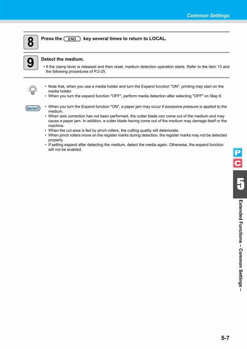
5-7
Common Settings
5
Extended Functions – Com
mon Settings –
8 Press the key several times to return to LOCAL.
9 Detect the medium.• If the clamp lever is released and then reset, medium detection operation starts. Refer to the item 13 and
the following procedures of P.2-25.
• Note that, when you use a media holder and turn the Expand function "ON", printing may start on the media holder.
• When you turn the expand function "OFF", perform media detection after selecting "OFF" on Step 6.
• When you turn the Expand function "ON", a paper jam may occur if excessive pressure is applied to the medium.
• When axis correction has not been performed, the cutter blade can come out of the medium and may cause a paper jam. In addition, a cutter blade having come out of the medium may damage itself or the machine.
• When the cut area is fed by pinch rollers, the cutting quality will deteriorate.• When pinch rollers move on the register marks during detection, the register marks may not be detected
properly. • If setting expand after detecting the medium, detect the media again. Otherwise, the expand function
will not be enabled.

5-8
Setting MarginsThe left and right margins of a medium to be printed or cut are set.
1 Press the key in LOCAL to select theprinting mode.
2 Press the key.
3 Press the key.
4 Press to select [MARGIN].
5 Press the key.
6 Press to set the left and right margins.
Item selection : Select the left or right margin with .Margin setting : Set the width of the margin with .
7 Press the key.
8 Press the key several times to end the setting.
Set Item Set Value OverviewLEFT 0 to 85 mm The left margin of a medium to be printed or cut is set.
RIGHT 0 to 85 mm The right margin of a medium to be printed or cut is set.
< LOCA L . 1 > [ # 0 1 ]WI DTH : * * * * mm
FUNCT I ONCOMMON SETUP < ENT >
COMMON SETUPPR SETUP < e n t >
COMMON SETUPMARG I N < e n t >
L EF T : R I GHT0mm : 0mm
L EF T : R I GHT0mm : 0mm
Left margin: 0 to 85 mm
(by the unit of 1 mm)
Right margin: 0 to 85 mm
(by the unit of 1 mm)
COMMON SETUPMARG I N < e n t >

5-9
Common Settings
5
Extended Functions – Com
mon Settings –
Setting the RECEIVED DATAThe setting can be changed for printing/cutting using an application other than those that come standard withthis machine.
1 Press the key in LOCAL.
2 Press to select [COMMON SETUP].
3 Press the key.
4 Press to select [RECEIVED DATA].
5 Press the key.
6 Press to select a set value.• Set value: AUTO, MANUAL
7 Press the key.
8 Press the key several times to end the setting.
Set Value Overview
AUTO When the standard application included with the machine is used, printing/cutting will be executedautomatically according to the type of the received data.
MANUAL
Set this parameter when executing printing/cutting with the application other than those that come withthe machine (RasterLinkPro4 or later/FineCut7 or later *1).In this case, this machine operates as follows. If the machine receives different data, an error occurs.
While in PRINT mode : The machine can only receive the print data. If the received data is not theprint data, an error occurs.
While in CUT mode : The machine can only receive the cut data. If the received data is not the cutdata, an error occurs.
*1. When has not been displayed at the lower left of the dialog of FineCut7 (or later), configure this setting.
FUNCT I ONSETUP < ENT >
FUNCT I ONCOMMON SETUP < ENT >
COMMON SETUPPR SETUP < e n t >
COMMON SETUPRECE I VED DATA < e n t >
RECE I VED DATASETUP : AUTO
COMMON SETUPRECE I VED DATA < e n t >

5-10
Setting Time
1 Press the key in LOCAL.
2 Press to select [COMMON SETUP].
3 Press the key.
4 Press to select [TIME SET].
5 Press the key twice.
6 Press to enter time.Select date (year/month/day/hour/minute): Select with .Enter date (year/month/day/hour/minute) : Enter with .
7 Press the key.• The entered date is displayed.
8 Press the key several times to end the setting.
• The time set in the past can be changed until only eight hours before the present displayed time.• When a future time after the present one has been set by mistake, performing the following operations
in Step 7 enables the already set future time to be restored to the previously set time.(1) Press the key in Step 7. (The entered time and the previously set time are displayed.)(2) Press the key.If you have made several changes in time setting, only the last time to be set can be restored to the previously set time. In addition, the time before change is ahead by the time that has elapsed.
FUNCT I ONSETUP < ENT >
FUNCT I ONCOMMON SETUP < ENT >
COMMON SETUPPR SETUP < e n t >
COMMON SETUPT I ME SET < e n t >
T I ME SET2 0 0 8 . 0 9 . 1 0 1 5 : 3 0 : 0 0
T I ME SET2 0 0 8 . 0 9 . 1 0 1 5 : 3 0 : 0 0

5-11
Common Settings
5
Extended Functions – Com
mon Settings –
Setting UnitsUnits used by this machine are set.
1 Press the key in LOCAL.
2 Press to select [COMMON SETUP].
3 Press the key.
4 Press to select [UNIT SETUP].
5 Press the key.
6 Press to select a unit.Item selection : Select one with .Unit setting : Enter with .
7 Press the key.
8 Press the key several times to end the setting.
FUNCT I ONSETUP < ENT >
FUNCT I ONCOMMON SETUP < ENT >
COMMON SETUPPR SETUP < e n t >
COMMON SETUPUN I T SETUP < e n t >
TEMP . : L ENGTH° C : mm
COMMON SETUPUN I T SETUP < e n t >

5-12
Setting the MACHINE NAMEThe names of machines (machine No.) are set for recognizing them when they are connected to one another witha USB 2.0 interface used.
1 Press the key in LOCAL.
2 Press to select [COMMON SETUP].
3 Press the key.
4 Press to select [MACHINE NAME].
5 Press the key.
6 Press to select a machine name (01 to 99).
7 Press the key.
8 Press the key several times to end the setting.
FUNCT I ONSETUP < ENT >
FUNCT I ONCOMMON SETUP < ENT >
COMMON SETUPPR SETUP < e n t >
COMMON SETUPMACH I NE NAME < e n t >
MACH I NE NAMEC J V 3 0 BS - 0 1
MACH I NE NAMEC J V 3 0 BS - 1 0
COMMON SETUPMACH I NE NAME < e n t >

Common Settings
5-13
5
Extended Functions – Com
mon Settings –
Setting a KEY BUZZERA buzzer sound when keys are pressed is set.
1 Press the key in LOCAL.
2 Press to select [COMMON SETUP].
3 Press the key.
4 Press to select [KEY BUZZER].
5 Press the key.
6 Press to select ON/OFF.
7 Press the key.
8 Press the key several times to end the setting.
• When the key buzzer is set to "OFF", the buzzer sound for errors, warnings, operation completion, etc. cannot be shut off.
FUNCT I ONSETUP < ENT >
FUNCT I ONCOMMON SETUP < ENT >
COMMON SETUPPR SETUP < e n t >
COMMON SETUPKEY BUZ ZER < e n t >
KEY BUZ ZERSETUP : ON
KEY BUZ ZERSETUP : OF F
COMMON SETUPKEY BUZ ZER < e n t >

5-14
Confirming Machine InformationThe information of this machine can be confirmed. The following items can be confirmed as machine information.
Displaying the Information
1 Press the key in LOCAL.• When you want to print the list of settings of this machine, set a
medium. ( P.2-15)
2 Press to select [COMMON SETUP].
3 Press the key.
4 Press to select [INFORMATION].
5 Press the key.
6 Press to select a type of information.
7 Press the key.• The Information you need is displayed.• When [List] or [Ink REPL. Report] is selected, the machine information is printed.
Item Overview
Error historyThis displays the history of errors and warnings to date.When you press , the date of occurrence (year/month/day/hour/minute) andthe error/warning information are displayed alternately in the order of occurrence.
Maintenance historyThis displays the date and time when the maintenance function was used.The maintenance history mainly describes the manual and automatic (regular or sleepmode) cleaning functions.
Printing mode historyThis displays the information of online printing (printing conditions) that has beenperformed to date since the machine's power-on. (Up to 50 pieces of information)When you press , the information is displayed in the order of printing.
List This allows you to print the settings of the machine. You can print the settings accordingto four categories. ( P.5-16)
Ink REPL. Report *1
*1. This function is available for the firmware Ver. 2.20 and later.
Prints history of ink used on the machine.
Version This displays the version information of the machine.Serial No. This displays serial numbers.
FUNCT I ONSETUP < ENT >
FUNCT I ONCOMMON SETUP < ENT >
COMMON SETUPPR SETUP < e n t >
COMMON SETUPI NFORMAT I ON < e n t >
I NFORMAT I ONERROR H I STORY < e n t >

5-15
Confirming Machine Information
5
Extended Functions – Com
mon Settings –
About Displayed InformationThis section describes how to read displayed information.
Error historyThe date of occurrence (year/month/day) is displayed.
The details of an error is displayed.
Maintenance historyThe details of maintenanceis displayed.
VersionVersion information, such as F/W,is displayed.
Printing mode historyResolution, length of a printed medium, etc. are displayed.
The date (year/month/day) of printing is displayed.
Serial No.Serial number is displayed.
ERROR H I STORY0 0 0 1 0 8 . 1 0 . 1 0 1 2 : 1 5
* * * * * ERROR 0 9 * * * * *HDC ERROR ( - - - - )
0 0 0 1 0 8 . 1 0 . 1 0 1 2 : 1 5> > CARR I AGE OU T
C J V 3 0 - 6 0 B S V 1 . 0 0MR L - I I I V 1 . 0 0
[ 0 1 ] 7 2 0 x 1 0 8 0 . 1 2B d . V d . x 1 . 1 L : 1 2 . 3 4m
PR I N Tmo d e H I S T .[ 0 1 ] 0 8 . 1 0 . 1 0 1 2 : 1 5
S ER I A L N o0 0 0 0 0 0 0 0

Confirming Machine Information
5-16
Printing the List of SettingsYou can print the settings of this machine by selecting one from the following four types.
1 Press the key in LOCAL.• When you want to print the list of settings of this machine, set a
medium. ( P.2-15)
2 Press to select [COMMON SETUP].
3 Press the key.
4 Press to select [INFORMATION].
5 Press the key.
6 Press to select [LIST].
7 Press the key.
8 Press to select a list to print.
9 Press the key.• Printing starts.
List Type OverviewPrinting mode The settings in the printing mode are printed.Cutting mode The settings in the cutting mode are printed.
Running meter A running meter is printed.All All lists are printed.
• When detecting the medium and the mode is in cut mode, if you perform printing in the list as it is, the following screen will be displayed by pressing the key in Step 7. In this case, press the
key to switch the setting of the pinch roller pressure to the print mode and then perform printing.
• If the key is pressed, switching operation will not be performed. ! PR PRESSURE : CUT !
SWI TCH : e n t
FUNCT I ONSETUP < ENT >
FUNCT I ONCOMMON SETUP < ENT >
COMMON SETUPPR SETUP < e n t >
COMMON SETUPI NFORMAT I ON < e n t >
I NFORMAT I ONERROR H I STORY < e n t >
I NFORMAT I ONL I ST < e n t >
L I STSE L ECT : PR I NT MODE

This chapter
describes the items required to use this machine more comfortably, which are themethods for the daily care, the maintenance of the ink unit etc.
Maintenance ................................................ 6-2Precautions for Maintenance ...................... 6-2About Cleaning Solution .............................. 6-2Cleaning the Exterior Surfaces ................... 6-3Cleaning the Platen ..................................... 6-3Cleaning the Media Sensor and Register Mark Sensor ................................................ 6-4Cleaning the Medium Holder ....................... 6-4
Maintaining the Capping Station ............... 6-5Cleaning the Wiper and Cap ....................... 6-6Replacing the Wiper .................................... 6-8Before Washing the Ink Discharge Passage ...................................................... 6-9Cleaning the Head Nozzles ....................... 6-11Washing the Ink Discharge Passage (PUMP Tube Washing) ............................. 6-13When not using for a long term (CUSTODY WASH) (firmware Ver.2.20 or older) ...... 6-14When not using for a long term (firmware Ver. 2.30 or later) ...................... 6-16
Cleaning the Ink Head and the Area around It..................................................... 6-19When Nozzle Clogging Cannot Be Solved ........................................................ 6-21
FILL UP INK .............................................. 6-21DISCHARGE & WASH .............................. 6-22Supplying the Machine with Ink Anew ....... 6-24
Preventing Nozzle Clogging When the Power Is OFF ............................................. 6-26
Setting the Refreshing Interval in the Sleep Mode ..........................................................6-27Setting the Tube Washing Interval in the Sleep Mode ................................................6-28Setting the Cleaning Interval in the Sleep Mode ..........................................................6-29
Setting Regular Operations...................... 6-30Setting the Regular Wiping Operation during a Printing Operation ...................................6-31Setting the Refreshing Interval in the Standby Mode ............................................6-33Setting the Interval between Each PUMP Tube Washing Operation in the Standby Mode ..6-34Setting the Cleaning Interval in the Standby Mode ..........................................................6-35
Other Maintenance Functions.................. 6-36Changing the Time When a Warning about Wiper Replacement Is Issued ....................6-36Setting the Display of Media Residual .......6-37If a Waste Ink Tank Confirmation Message Appears .....................................................6-39
Replacing the Cutter Blade ...................... 6-43Replacing the Pinch Rollers..................... 6-45Replacing a Cutter Blade Not Included in the Accessories......................................... 6-46
Chapter 6Maintenance

6-2
MaintenanceMaintain the machine regularly or as necessary so that its accuracy will be maintained and it can continue to beused for a long time.
Precautions for MaintenancePay attention to the following items when maintaining this machine.
About Cleaning SolutionUse the cleaning solution corresponding to the BS* ink.
• When using cleaning solution for maintenance, be sure to wear the supplied protective glasses.
• The ink contains organic solvent. When cleaning the machine, be sure to wear gloves so that no ink willmake direct contact with your skin.
• Never disassemble the machine. Disassembling it can result in electric shock hazards or damage to themachine. Before maintenance, be sure to turn off the power switch and unplug the power cable; otherwise, anunexpected accident may occur.
• Prevent moisture from entering the machine. Moisture inside the machine can cause electric shockhazards or damage to the machine.
• To ensure stable ink jetting, it is necessary for the machine to eject a small amount of ink (flushing)regularly when a printing (outputting) operation has not been performed for a long time.
• When the machine is not to be used for a long time, turn off only the power switch on the front side, leavethe main power switch at the rear turned ON (in the position of | ), and leave the power cable connected.
• If organic solvent ink is mixed with water or alcohol, coagulation is generated. Do not wipe the nozzle face of the heads, wiper, caps, etc. with water or alcohol. Doing so can causenozzle clogging or machine failure.
• Do not use benzene, thinner, or any chemical agent containing an abrasive. Such materials candeteriorate or deform the surface of the cover.
• Do not apply a lubricant, etc. to any parts inside the machine. Doing so can cause damage to the plottermechanism.
• Be careful that the cleaning solution, ink, etc. not to stick to the cover because this may cause thesurface of the cover to deteriorate or deform.
Ink type Applicable cleaning solution for maintenance
BS* ink Cleaning Solution 200 for Solvent Ink (SPC-0369)MILD SOLVENT WASHING LIQUID (SPC-0294)

6-3
Maintenance
6 6
Maintenance
Cleaning the Exterior SurfacesWhen the exterior surfaces of the machine are stained, dampen a soft cloth with water or a neutral detergentdiluted with water, squeeze it, and wipe the surfaces with the cloth.
Cleaning the PlatenThe platen easily gets dirty with lint, paper dust, etc. generated when a medium is cut. Wipe off conspicuous stains with a soft-hair brush, a dry cloth, a paper towel, etc.
• When the platen is stained with ink, wipe it off with a paper towel containing a small amount of cleaningsolution for maintenance.
• Before cleaning the platen, make sure that the platen has cooled adequately.• Because dust and dirt are easily accumulated in the slots for holding a medium and cutting paper (cutter
line), be sure to clean these parts carefully.

Maintenance
6-4
Cleaning the Media Sensor and Register Mark SensorWhen the sensor is covered with dust, etc., it may cause false detection of media or register marks.Using a cotton swab, remove the dust, etc. accumulated on the surface of the sensor.
When cleaning the sensor on the undersurface of the cutter unit, perform the operations on P. 6-19 "Cleaning theInk Head and the Area around It" Steps 1 and 2 and move the carriage to the left end.
Cleaning the Medium HolderWhen the medium holder is covered with lint, dust, etc., a medium cannot be fed normally during printing or duststicks to the nozzles, which may result in abnormal printing.Clean the medium holder regularly.
Media sensor
Media sensor: On the platen at the rear Register mark sensor: On the undersurface of the cutter unit
Mark sensor
Medium holder

6-5
6
Maintenance
Maintaining the Capping StationMaintain the ink cap, wiper, etc. located in the capping station. (ST.MAINTENANCE)
The ink cap and wiper function as follows.• Wiper : It wipes off ink sticking to the head nozzles.• Ink cap : It prevents the head nozzles from clogging due to dryness.
As the machine is used repeatedly, the wiper and ink cap gradually become dirty with ink, dust, etc.If nozzle missing cannot be corrected even after head cleaning ( P.2-40) has been performed, use a cleaningkit and clean stick.
Tools required for maintenance
• Kit of cleaning solution for maintenanceCleaning solution 200 for Solvent Ink (SPC-0369)
• Clean stick (SPC-0527) • Gloves • Goggles
• Be sure to wear the supplied goggles and gloves when maintaining the capping station. Otherwise, youmay get ink in your eyes.
• Do not move the carriage out of the capping station by hand. When you want to move the carriage,perform the operations on P.6-6 Steps 1 and 4.

6-6
Cleaning the Wiper and CapIt is recommended that the wiper and cap be cleaned frequently in order to maintain the high image quality of themachine and keep the machine itself in good working order.
1 Press the key in LOCAL to select theprinting mode.
2 Select [ST. MAINTENANCE] of the maintenance menu.(1) Press the key.(2) Press to select [MAINTENANCE] and press the key.
3 Press the key.
4 Press the key.• The carriage moves onto the platen.
5 Remove the wiper.• Pull out the wiper by holding the protrusions at its both ends.
6 Clean the wiper and bracket.• Wipe off the ink sticking to the wiper and bracket with a clean
stick dipped in cleaning solution for maintenance.
• Clean the wiper and the area around it about twice a week (it varies, depending on frequency in the useof the machine).
• Replace the wiper with a new one when it is extremely dirty or bent. ( P.6-8)• When cleaning the wiper, be careful that lint from the clean stick does not get left on the wiper.
Remaining lint may cause image quality to deteriorate.
< LOCA L . 1 > [ # 0 1 ]WI DTH : * * * * mm
ST . MA I NTENANCECARR I AGE OUT < e n t >
Protrusion
Wiper
Bracket

6-7
Maintaining the Capping Station
6 6
Maintenance
7 Clean the wiper slider.• Wipe off the ink sticking to the wiper slider with a clean stick
dipped in cleaning solution for maintenance.
8 Return the wiper to its original position.• Insert the wiper by holding its both ends.
9 Clean the cap rubber and wiper cover.• Wipe off the ink sticking to the cap rubber and wiper cover
with a clean stick dipped in cleaning solution for maintenance.
10 Press the key.• After its initial operation, the machine returns to LOCAL.
Wiper slider
Protrusion
Cap rubber
Wiper cover
* B e i n g I n i t i a l i z e d *P L EASE WA I T

6-8
Replacing the WiperThe wiper is consumable. When the message shown on the right appears,replace the wiper immediately.In addition, wipe off the ink sticking to the undersurface of the slider.
1 Press the key in LOCAL to select theprinting mode.
2 Select [ST. MAINTENANCE] of the maintenance menu.(1) Press the key.(2) Press to select [MAINTENANCE] and press the key.
3 Press the key.
4 Press to select [WIPER REPLACE].
5 Press the key.• The carriage moves onto the platen.
6 Remove the wiper.• Pull out the wiper by holding the protrusions at its both ends.
7 Insert a new wiper.• Insert a new wiper by holding its both ends.
8 Press the key.• After its initial operation, the machine returns to LOCAL.
• A cleaning wiper is an option. Buy one through the dealer in your region or at our service office.• Do not select [WIPER REPLACE] at any time other than when the wiper is replaced. Once it is selected,
the counter that counts the number of times the wiper is used is reset.
< LOCA L . 1 > [ # 0 1 ]! Re p l a c e a WI PER
< LOCA L . 1 > [ # 0 1 ]WI DTH : * * * * mm
ST . MA I NTENANCECARR I AGE OUT < e n t >
ST . MA I NTENANCEWI PER REP L ACE < e n t >
ST . MA I NTENANCECOMP L ETED : e n t
Protrusion
Protrusion
* B e i n g I n i t i a l i z e d *P L EASE WA I T
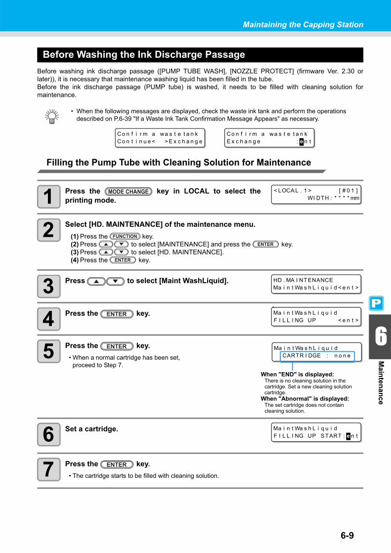
6-9
Maintaining the Capping Station
6 6
Maintenance
Before Washing the Ink Discharge PassageBefore washing ink discharge passage ([PUMP TUBE WASH], [NOZZLE PROTECT] (firmware Ver. 2.30 orlater)), it is necessary that maintenance washing liquid has been filled in the tube.Before the ink discharge passage (PUMP tube) is washed, it needs to be filled with cleaning solution formaintenance.
Filling the Pump Tube with Cleaning Solution for Maintenance
1 Press the key in LOCAL to select theprinting mode.
2 Select [HD. MAINTENANCE] of the maintenance menu.(1) Press the key.(2) Press to select [MAINTENANCE] and press the key.(3) Press to select [HD. MAINTENANCE].(4) Press the key.
3 Press to select [Maint WashLiquid].
4 Press the key.
5 Press the key.• When a normal cartridge has been set,
proceed to Step 7.
6 Set a cartridge.
7 Press the key.• The cartridge starts to be filled with cleaning solution.
• When the following messages are displayed, check the waste ink tank and perform the operations described on P.6-39 "If a Waste Ink Tank Confirmation Message Appears" as necessary.
Co n f i r m a wa s t e t a n kCo n t i n u e < > E x c h a n g e
Co n f i r m a wa s t e t a n kE x c h a n g e : e n t
< LOCA L . 1 > [ # 0 1 ]WI DTH : * * * * mm
HD . MA I NTENANCEMa i n t Wa s h L i q u i d < e n t >
Ma i n t Wa s h L i q u i dF I L L I NG UP < e n t >
Ma i n t Wa s h L i q u i dCARTR I DGE : n o n e
When "END" is displayed:There is no cleaning solution in the cartridge. Set a new cleaning solution cartridge.
When "Abnormal" is displayed:The set cartridge does not contain cleaning solution.
Ma i n t Wa s h L i q u i dF I L L I NG UP START : e n t

6-10
Discharging Cleaning Solution for MaintenancePerform the following operations to discharge the cleaning solution in the tube.
1 Press the key in LOCAL to select theprinting mode.
2 Select [HD. MAINTENANCE] of the maintenance menu.(1) Press the key.(2) Press to select [MAINTENANCE] and press the key.(3) Press to select [HD. MAINTENANCE].(4) Press the key.
3 Press to select [Maint WashLiquid].
4 Press the key.
5 Press to select [DISCHARGE].
6 Press the key.• When the cartridge has been disengaged, proceed to Step 8.
7 Remove the cartridge.
8 Press the key.• The cleaning solution starts to be discharged.
< LOCA L . 1 > [ # 0 1 ]WI DTH : * * * * mm
HD . MA I NTENANCEMa i n t Wa s h L i q u i d < e n t >
Ma i n t Wa s h L i q u i dF I L L I NG UP < e n t >
Ma i n t Wa s h L i q u i dD I SCHARGE < e n t >
Ma i n t Wa s h L i q u i dT h e r e i s a CARTR I DGE
Ma i n t Wa s h L i q u i dD I SCHARGE START : e n t

6-11
Maintaining the Capping Station
6 6
Maintenance
Cleaning the Head NozzlesThe head nozzles need to be washed to prevent them from being clogged with coagulated ink.
1 Press the key in LOCAL to select theprinting mode.
2 Select [ST. MAINTENANCE] of the maintenance menu.(1) Press the key.(2) Press to select [MAINTENANCE] and press the key.
3 Press the key.
4 Press to select [NOZZLE WASH].
5 Press the key.• The carriage moves onto the platen.
6 Clean the wiper and bracket.(1) Pull out the wiper by holding the protrusions at its both ends.(2) Clean the wiper and bracket with a clean stick dipped in cleaning solution for maintenance
(SPC-0369).(3) Insert the wiper into the original position by holding the protrusions at its both ends.
7 Press the key.
Check the items on the rightbeforehand.
Is [NEAR END] or [INK END] displayed?• The cleaning solution or ink is absorbed when the nozzles are washed.
At this time, if the state of "no ink" or "almost no ink" is detected, the nozzlewashing operation cannot start.
• Replace the cartridge with another from which the state of "almost no ink" or "noink" is not detected.
< LOCA L . 1 > [ # 0 1 ]WI DTH : * * * * mm
ST . MA I NTENANCECARR I AGE OUT < e n t >
ST . MA I NTENANCENOZ Z L E WASH < e n t >
WI PER CL EAN I NGCOMP L ETED ( NEXT ) : e n t
Protrusion
F i l l t h e l i q u i dCOMP L ETED ( NEXT ) : e n t

6-12
8 Press the key and fill up the cap with cleaning solution for maintenance.
• When you press the key, cleaning solution dripsinto the cap.
• When you press the key again, the solution stopsdripping.
• Repeat the drops several times to fill the cap with the cleaningsolution just before the solution overflows from the cap.
9 Press the key.
10 Press to set the time for the cleaningsolution to be left as it is.
• Set value: 1 to 99 min (by the unit of 1 min)
11 Press the key.• The cleaning solution in the cap is absorbed.• The screen on the right is displayed for the time set in Step 10.• When the set time has elapsed, the screen returns to LOCAL.
• When nozzle missing is not corrected even after this cleaning has been performed several times,perform "When Nozzle Clogging Cannot Be Solved" ( P.6-21) and "DISCHARGE & WASH" ( P.6-22). When the problem is not solved even after the operation above, contact the distributor in yourregion or our service office.
• When this machine is not filled with cleaning solution for maintenance, do the following:(1) Perform the operations in Steps 1 to 5.(2) Fill up the cap with cleaning solution for maintenance, using a syringe.(3) Perform the operations in Step 9 and later.
• The waste ink discharged by head nozzle cleaning is not counted as the waste ink automaticallyaccumulated in this device ( P.6-39). Check the status of the waste ink tank without fail before/afterthe cleaning.
ST . MA I NTENANCEL EAV I NG T I ME : 1m i n
ST . MA I NTENANCEL EAV I NG T I ME : 2m i n
* B e i n g I n i t i a l i z e d *P L EASE WA I T
< LOCA L . 1 > [ # 0 1 ]
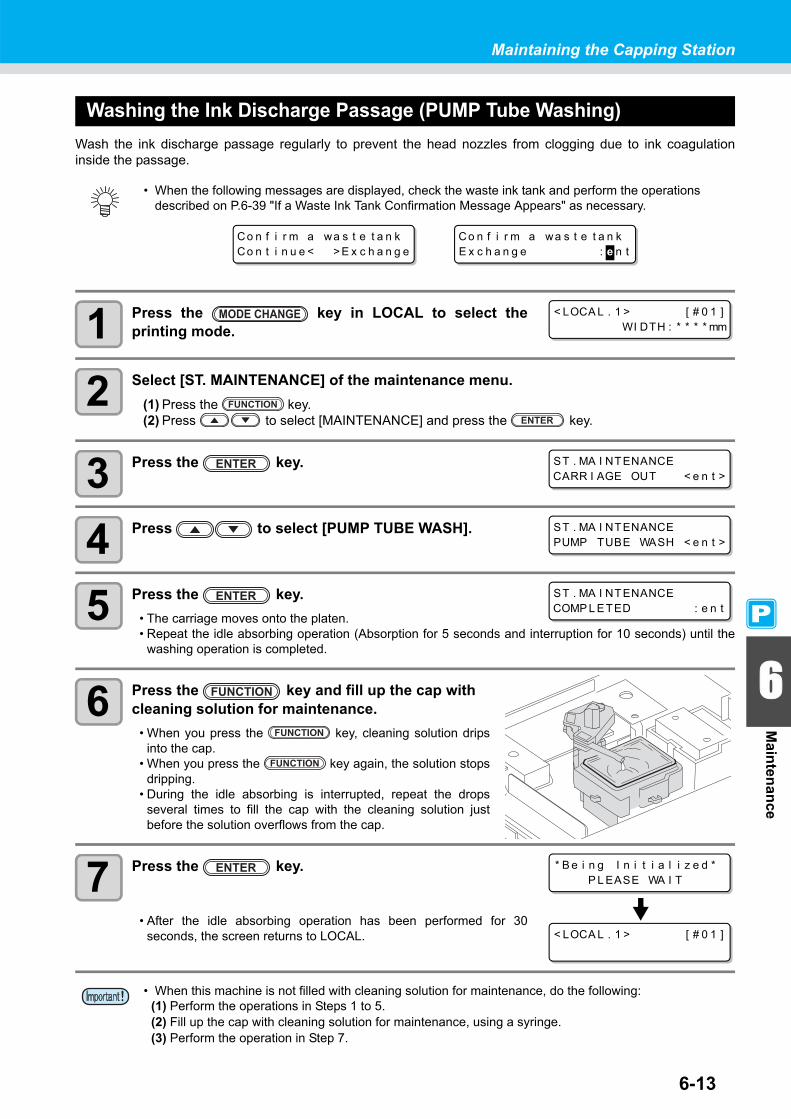
6-13
Maintaining the Capping Station
6 6
Maintenance
Washing the Ink Discharge Passage (PUMP Tube Washing)Wash the ink discharge passage regularly to prevent the head nozzles from clogging due to ink coagulationinside the passage.
1 Press the key in LOCAL to select theprinting mode.
2 Select [ST. MAINTENANCE] of the maintenance menu.(1) Press the key.(2) Press to select [MAINTENANCE] and press the key.
3 Press the key.
4 Press to select [PUMP TUBE WASH].
5 Press the key.• The carriage moves onto the platen.• Repeat the idle absorbing operation (Absorption for 5 seconds and interruption for 10 seconds) until the
washing operation is completed.
6 Press the key and fill up the cap with cleaning solution for maintenance.
• When you press the key, cleaning solution dripsinto the cap.
• When you press the key again, the solution stopsdripping.
• During the idle absorbing is interrupted, repeat the dropsseveral times to fill the cap with the cleaning solution justbefore the solution overflows from the cap.
7 Press the key.
• After the idle absorbing operation has been performed for 30seconds, the screen returns to LOCAL.
• When the following messages are displayed, check the waste ink tank and perform the operations described on P.6-39 "If a Waste Ink Tank Confirmation Message Appears" as necessary.
• When this machine is not filled with cleaning solution for maintenance, do the following:(1) Perform the operations in Steps 1 to 5.(2) Fill up the cap with cleaning solution for maintenance, using a syringe.(3) Perform the operation in Step 7.
Co n f i r m a wa s t e t a n kCo n t i n u e < > E x c h a n g e
Co n f i r m a wa s t e t a n kE x c h a n g e : e n t
< LOCA L . 1 > [ # 0 1 ]WI DTH : * * * * mm
ST . MA I NTENANCECARR I AGE OUT < e n t >
ST . MA I NTENANCEPUMP TUBE WASH < e n t >
ST . MA I NTENANCECOMP L ETED : e n t
* B e i n g I n i t i a l i z e d *P L EASE WA I T
< LOCA L . 1 > [ # 0 1 ]

6-14
When not using for a long term (CUSTODY WASH) (firmware Ver.2.20 or older)When the machine is not going to be used for a week or more, use the cleaning function for custody to clean thehead nozzles and ink discharge passage. After this, keep the machine in custody.This function is available for the firmware Ver. 2.20 or earlier.
1 Press the key in LOCAL to select theprinting mode.
2 Select [ST. MAINTENANCE] of the maintenance menu.(1) Press the key.(2) Press to select [MAINTENANCE] and press the key.
3 Press the key.
4 Press to select [COSTODY WASH].
5 Press the key.• The carriage moves onto the platen.
6 Clean the wiper and bracket.(1) Pull out the wiper by holding the protrusions at its both ends.(2) Clean the wiper and bracket with a clean stick dipped in cleaning solution for maintenance
(SPC-0369).(3) Insert the wiper into the original position by holding the protrusions at its both ends.
Check the items on the rightbeforehand.
Is [NEAR END] or [INK END] displayed?• The cleaning solution or ink is absorbed when the nozzles are washed.
At this time, if the state of "no ink" or "almost no ink" is detected, the nozzlewashing operation cannot start.
• Replace the cartridge with another from which the state of "almost no ink" or "noink" is not detected.
• When the following messages are displayed, check the waste ink tank and perform the operations described on P.6-39 "If a Waste Ink Tank Confirmation Message Appears" as necessary.
Co n f i r m a wa s t e t a n kCo n t i n u e < > E x c h a n g e
Co n f i r m a wa s t e t a n kE x c h a n g e : e n t
< LOCA L . 1 > [ # 0 1 ]WI DTH : * * * * mm
ST . MA I NTENANCECARR I AGE OUT < e n t >
ST . MA I NTENANCECOSTODY WASH < e n t >
WI PER CL EAN I NGCOMP L ETED ( NEXT ) : e n t
Protrusion

6-15
Maintaining the Capping Station
6 6
Maintenance
7 Press the key.
8 Press the key and fill up the cap with cleaning solution for maintenance.
• When you press the key, cleaning solution dripsinto the cap.
• When you press the key again, the solution stopsdripping.
• Repeat the drops several times to fill the cap with the cleaningsolution just before the solution overflows from the cap.
9 Press the key.
10 Press to set the time for the cleaningsolution to be left as it is.
• Set value: 1 to 99 min (by the unit of 1 min)
11 Press the key.• The nozzles are washed.• When the nozzles have been completely washed, the head moves
onto the platen.
12 Press the key and fill up the cap withcleaning solution for maintenance.
• When you press the key, cleaning solution dripsinto the cap.
• When you press the key again, the solution stopsdripping.
• During the idle absorbing is interrupted, repeat the dropsseveral times to fill the cap with the cleaning solution justbefore the solution overflows from the cap.
13 Press the key.• After its initial operation, the machine returns to LOCAL.
F i l l t h e l i q u i d .COMP L ETED ( NEXT ) : e n t
ST . MA I NTENANCEL EAV I NG T I ME : 1m i n
ST . MA I NTENANCEL EAV I NG T I ME : 2m i n
* B e i n g I n i t i a l i z e d *P L EASE WA I T
* B e i n g I n i t i a l i z e d *P L EASE WA I T

6-16
When not using for a long term (firmware Ver. 2.30 or later)When the operation of the machine is to be suspended for 24 hours or more, use the NOZZLE PROTECTfunction to protect the nozzle surface.This function is available for the firmware Ver. 2.30 or later.
Execute the NOZZLE PROTECT function
1 Press the key in LOCAL to select theprinting mode.
2 Select [ST. MAINTENANCE] of the maintenance menu.(1) Press the key.(2) Press to select [MAINTENANCE] and press the key.
3 Press the key.
4 Press to select [NOZZLE PROTECT].
5 Press the key.• The carriage moves onto the platen.
6 Press the key.• The NOZZLE PROTECT function is executed.• When NOZZLE PROTECT function is finished, the power is automatically turned off and the machine
enters a nozzle protection status. • In the nozzle protection status, it executes NOZZLE PROTECT regularly. Keep the main power switch on.
Also, check that it has enough maintenance washing liquid.
Check the items on the rightbeforehand.
Has maintenance washing liquid been filled?• If maintenance washing liquid has not been filled, fill it by referring to P.6-9 “Filling the
Pump Tube with Cleaning Solution for Maintenance”.Hasn’t a warning occurred in the maintenance washing liquid cartridge?
• If the warning message of [Wash Liquid Cart. NONE], [Wash Liquid END] or [WRONGWASH CART.] is displayed, set a proper maintenance washing liquid cartridge to solvethe warning.
• When the following messages are displayed, check the waste ink tank and perform the operationsdescribed on P.6-39 "If a Waste Ink Tank Confirmation Message Appears" as necessary.
• In the nozzle protection status, maintenance in the sleep status does not work.• If the power is turned on after executing NOZZLE PROTECT function,
this machine automatically performs (1) and (2) described below andthen displays a message shown in the right. After checking themessage, perform test drawing to check the nozzle status.
(1) Discharges washing liquid filled in the cap.(2) Executes normal cleaning of the head cleaning automatically.
Co n f i r m a wa s t e t a n kCo n t i n u e < > E x c h a n g e
Co n f i r m a wa s t e t a n kE x c h a n g e : e n t
< LOCA L . 1 > [ # 0 1 ]WI DTH : * * * * mm
ST . MA I NTENANCECARR I AGE OUT < e n t >
ST . MA I NTENANCENOZ Z L E PROTECT < e n t >
NOZ Z L E PROTECTEXECUTE : e n t
< L OC A L . 1 > [ # 0 1 ]! D o T E S T D R AW

6-17
Maintaining the Capping Station
6 6
Maintenance
Executes the NOZZLE PROTECT function automaticallyYou can set the status to enter the nozzle protection automatically (auto-execute function of NOZZLE PROTECT)in case the device is not used for a certain amount of time.In the nozzle protection status, NOZZLE PROTECT can be automatically executed regularly.
To use the auto-execute function of NOZZLE PROTECT, set the following items.• On Time : Time from the stop of the device to the start of the nozzle protection status. • Interval : Execution interval of NOZZLE PROTECT in the nozzle protection status.
1 Press the key in LOCAL to select theprinting mode.
2 Select [AutoNZL.PROTECT] of the maintenance menu.(1) Press the key.(2) Press to select [MAINTENANCE] and press the key.(3) Press to select [AutoNZL.PROTECT] .
3 Press the key.
4 Press to select [ON Time].
• The machine not being used means that it is in the standby status or the status that the power supplyswitch under the operation panel is OFF (the sleep status).
• The followings are the examples (three patterns) if you set the time length until the NOZZLE PROTECTfunction is executed to “16h”.
In the nozzle protection status *2In use On standby *1
Executing NOZZLE PROTECT
In use In sleep status *1
In use On standby *1
Power switch OFF
In sleep status *1
Power switch OFF
*1 : If the time length set in P.4-31 “Setting Routine operations” and P.4-28 “Preventing nozzle clogging while power-off” has passed, maintenance operation is executed automatically.
*2 : In the nozzle protection status, a maintenance function set at P.4-28 “Preventing nozzle clogging while power-off” does not work.After entering the nozzle protection status, this machine automatically performs NOZZLE PROTECT regularly.
Executing NOZZLE PROTECT
Executing NOZZLE PROTECT
In the nozzle protection status *2
In the nozzle protection status *2
< LOCA L . 1 > [ # 0 1 ]WI DTH : * * * * mm
A u t oNZ L . PROTECTON T i me < e n t >
A u t oNZ L . PROTECTON T i me < e n t >

Maintaining the Capping Station
6-18
5 Press the key.
6 By pressing the keys, set the time length until the NOZZLE PROTECT is executed.
• Set value:OFF, 1 to 24 hours
7 Press the key.• “ON Time” setting ends. Following this, set “Interval”.• “Interval” is set to seven days as default. If changing is not needed,
press the key several times to end the setting.
8 Select [Interval] by pressing the keys.
9 Press the key.
10 Press the keys to set an execution interval(number of days) of NOZZLE PROTECT.
• Set value:OFF, 1 to 14 days
11 Press the key.• Press the key several times to end.
• If maintenance washing liquid has not been filled in the machine, thescreen on the right is displayed in the Step 5. Fill maintenancewashing liquid and execute procedures from the Step 1 again.
A u t oNZ L . PROTECTON T i me = 1 6 h
A u t oNZ L . PROTECTON T i me = 1 2 h
A u t oNZ L . PROTECTON T i me < e n t >
A u t oNZ L . PROTECTI n t e r v a l < e n t >
A u t oNZ L . PROTECT i n t v lON T i me = 7 d
A u t oNZ L . PROTECT i n t v lON T i me = 1 0 d
MA I NTENANCEA u t oNZ L . CUSTODY < e n t >
* * Wa s h i n g l i q u i d * ** * u n - f i l l i n g u p . * *

6-19
6
Maintenance
Cleaning the Ink Head and the Area around ItBecause the ink head employs a very precise mechanism, due care needs to be taken when it is cleaned.Using a clean stick, etc., rub off gelatinous ink or dust that may stick to the lower part of the slider and the areaaround the ink head. In doing so, never rub the nozzles of the head.
1 Press the key in LOCAL to select theprinting mode.
2 Select [ CR.MAINTENANCE ] of the maintenance menu.(1)Press the key.(2)Press to select [ MAINTENANCE ] and press the key.(3)Press to select [ CR.MAINTENANCE ] and press the
key.
3 Remove the maintenance cover.(1)Turn the two screws that fix the maintenance cover
counterclockwise to remove them.(2)Remove the maintenance cover.
4 Press the key.
5 Press the key.
• Carriage will move to the left end of this device.
Tools needed for cleaning • Clean stick • Gloves • Goggles
• Be sure to wear the attached goggles and gloves when cleaning the area around the ink head.Otherwise, you may get ink in your eyes.
• The ink contains organic solvent. If you get the ink on your skin or in your eyes, wash it away with plentyof water immediately.
• You can move the carriage manually, however, if you connect the connection unit to thecutter unit, you cannot move it manually because it is locked. If you try to move forcibly, itmay cause injury.
< LOCA L . 1 > [ # 0 1 ]WI DTH : * * * * mm
CR . MA I NTENANCERemo v e t h e c o v e r : e n t
Screw
Maintenance cover
Turn it counterclockwise.
CR . MA I NTENANCECARR I AGE OUT : e n t

Cleaning the Ink Head and the Area around It
6-20
6 Wipe off the ink sticking to the side of the ink head with a clean stick.• Never rub the nozzles.
7 When the cleaning has been completed, press the key.
• After its initial operation, the machine returns to LOCAL.
• Clean the area around the ink head about twice a week (it varies, depending on the frequency themachine is used).
Clean the side (in dark gray) of the ink head with a clean stick.
Nozzles (Never touch them.)
Clean this with a clean stick or waste cloth.
* B e i n g I n i t i a l i z e d *P L EASE WA I T

6-21
6
Maintenance
When Nozzle Clogging Cannot Be SolvedWhen nozzle clogging cannot be solved even after the ink head cleaning ( P.2-40) or head nozzle washing( P.6-11) has been done, perform the following two functions:
FILL UP INK
1 Press the key in LOCAL to select theprinting mode.
2 Select [HD. MAINTENANCE] of the maintenance menu.(1)Press the key.(2)Press to select [MAINTENANCE] and press the key.(3)Press to select [HD. MAINTENANCE].(4)Press the key.
3 Press the key.• Ink is supplied automatically.
• When ink has been supplied completely, the screen returns to theshown on the right.
4 Press the key several times to end the setting.
When 600cc cartridge is usedEven when [Ink Level] is displayed, enough ink for head cleaning may remain in the ink pack.When [Ink Level] appears, see "When [Ink Level] is displayed" in the provided manual "When using 600 cc cartridge" and enter the current weight of the 600cc cartridge.
When the remaining ink is not enough for head cleaningWhen the remaining ink is not enough for head cleaning, an error shown on the right appears on the step 3. Replace with a new ink pack, and then perform head cleaning again.
FILL UP INK • Ink is supplied to solve nozzle clogging.
DISCHARGE & WASH • The head, tube, and damper are washed with dedicated cleaning solution (optional).( P.6-22)
< LOCA L . 1 > [ # 0 1 ]WI DTH : * * * * mm
F I L L I NG UP0 0 : 0 0
HD . MA I NTENANCEF I L L UP I NK < e n t >
* * * 6 0 0 c c E r r o r * * *s h o r t a g e o f i n k .

6-22
DISCHARGE & WASHInk is discharged from the head, damper, and tube for them to be cleaned.
1 Press the key in LOCAL to select theprinting mode.
2 Select [HD. MAINTENANCE] of the maintenance menu.(1)Press the key.(2)Press to select [MAINTENANCE] and press the key.(3)Press to select [HD. MAINTENANCE].(4)Press the key.
3 Press to select [DISCHARGE & WASH].
4 Press the key.
5 Remove the ink cartridge.• Ink remaining in the head or tube is discharged into the waste ink
tank.• When ink has been discharged completely, the screen on the right
appears.
6 Mount a cleaning solution cartridge on the ink station.• The cleaning solution starts to be absorbed.• When the cleaning solution has been absorbed completely, the
screen on the right appears.
7 Remove the cleaning solution cartridge.• The cleaning solution remaining in the head or tube is discharged
into the waste ink tank.• When the cleaning solution has been discharged completely, the
screen on the right appears.
• To use this function, the dedicated cleaning solution ( P.6-2"About Cleaning Solution") is required. Inaddition, before performing the work, check whether ink to be filled again remains or not.
• When the following messages are displayed, check the waste ink tank and perform the operationsdescribed on P.6-39 "If a Waste Ink Tank Confirmation Message Appears" as necessary.
Co n f i r m a wa s t e t a n kCo n t i n u e < > E x c h a n g e
Co n f i r m a wa s t e t a n kE x c h a n g e : e n t
< LOCA L . 1 > [ # 0 1 ]WI DTH : * * * * mm
MA I NTENANCED I SCHARGE&WASH < e n t >
Remo v e : I n k Ca r t r i d g eMMCCYYKK
* D I SCHARGE *0 0 : 0 0
S e t : Wa s h i n gCa r t r i d g e1 2 3 4 5 6 7 8
* ABSORPT I ON *0 0 : 0 0
Remo v e : Ca r t r i d g e s1 2 3 4 5 6 7 8
* D I SCHARGE *0 0 : 0 0
S e t : Wa s h i n gCa r t r i d g e1 2 3 4 5 6 7 8

6-23
When Nozzle Clogging Cannot Be Solved
6 6
Maintenance
8 Mount a cleaning solution cartridge on the ink station.• The cleaning solution starts to be absorbed.• When the cleaning solution has been absorbed completely, the
screen on the right appears.
9 Remove the cleaning solution cartridge.• The cleaning solution remaining in the head or tube is discharged
into the waste ink tank.
• When the cleaning solution has been discharged completely, thescreen on the right appears.
• Check the state of the waste ink tank and select whether to stop orresume cleaning.
• When you resume cleaning, press to return to Step 6.
10 Press .
11 Press the key several times to end the operation.
* ABSORPT I ON *0 0 : 0 0
Remo v e : Ca r t r i d g e s1 2 3 4 5 6 7 8
* D I SCHARGE *0 0 : 0 0
Ma i n t . Wa s h L i q u i dEND< >D I SCHARGE

6-24
Supplying the Machine with Ink AnewAfter you have performed [DISCHARGE & WASH], supply the machine with ink anew with the followingoperations.
1 Turn on the power of the machine.• When the power is turned on, the firmware version is displayed
following [BOOT].
2 Check the ink type to fill, and then press the key.
• To check the state of the cartridge, press the key. ( P.7-5)
3 Check the ink set (the color) to fill, and then press the key.
• You cannot change the current ink set to another by yourself.• If you want to change the ink set, contact our service office.
4 Press the key.
BOOT
C J V 3 0 BS - 6 0 V * . * *
P l e a s e Wa i t
I NK TYPEBS 2 S o l
BS 2 I NK SET4 - Co l o r ( MMCCYYKK )
S e t : BS 2 - 4 c o l o r I n k- - - - - - - -

When Nozzle Clogging Cannot Be Solved
6-25
6
Maintenance
5 Mount an ink cartridge on the ink station.
• When an ink cartridge has been set, the machine is supplied with inkautomatically.
• The ink station has an insertion slot allocated to each ink color. Set the ink cartridge according to thecartridge label under the ink station.
6 When ink has been supplied to the machine completely, the screen returns to LOCAL.
When the Machine Cannot Be Supplied with Ink in Step 5 When various ink errors including "Almost no ink" and "No ink" occur, ink does not start to be supplied to themachine.
When ink does not start to be supplied to the machine in Step 5:(1) Press the key to return to the screen in Step 2.(2) Press the key to check the state of the ink cartridge.(3) Correct ink errors ( P.7-5) and repeat the operations from Step 2.
• If blurring or missing of characters is found in printing after the machine has been supplied with inkanew, see "Perform head cleaning depending on the test printing result" ( P.2-40) or "FILL UP INK"( P.6-21).
S e t : BS 2 - 4 c o l o r I n k- - C - Y - KK
F I L L I NG UP NOW.0 0 : 0 0
Front side
< LOCA L . 1 > [ # 0 1 ]WI DTH : * * * * mm

6-26
Preventing Nozzle Clogging When the Power Is OFFEven when the power switch is off, the machine starts regularly and performs various operations to preventnozzle clogging (Sleep mode). In the sleep mode, the following items can be set:
Default value
Set Item Set Value Overview
REFRESH
OFF/1 to 168 hours
The interval between each refreshing operation is set.
PUMP TUBE WASH The interval between each PUMP tube washing operation is set.
CLEANING The interval between each cleaning operation is set.
Ink Type Refreshing PUMP Tube Washing Cleaning
BS* 4 hours 48 hours OFF
• When the message on the right is displayed, the operations set inthe sleep mode are not performed. Perform the operationsdescribed on P.6-39 as necessary.
• When you turn off the power switch on the front side of the machine,check the state of the waste ink tank.
< LOCA L . 1 > [ # 0 1 ]! WASTE TANK

6-27
Preventing Nozzle Clogging When the Power Is OFF
6 6
Maintenance
Setting the Refreshing Interval in the Sleep ModeThe interval between each operation of ejecting a small amount of ink from the nozzles to prevent nozzleclogging is set.
1 Press the key in LOCAL to select theprinting mode.
2 Select [SLEEP SETUP] of the maintenance menu.(1)Press the key.(2)Press to select [MAINTENANCE] and press the key.(3)Press to select [SLEEP SETUP].
3 Press the key.
4 Press the key.
5 Press to set the refreshing interval.• Set value: OFF or 1 to 168 hours
6 Press the key.
7 Press the key several times to end the setting.
< LOCA L . 1 > [ # 0 1 ]WI DTH : * * * * mm
S L EEP SETUPREFRESH < e n t >
S L EEP SETUPREFRESH i n t e r v a l = 1 h
S L EEP SETUPREFRESH i n t e r v a l = 1 0 h
S L EEP SETUPREFRESH < e n t >

6-28
Setting the Tube Washing Interval in the Sleep ModeThe interval between each operation of washing the cap and PUMP tube with cleaning solution for maintenancein the sleep mode is set.
1 Press the key in LOCAL to select theprinting mode.
2 Select [SLEEP SETUP] of the maintenance menu.(1)Press the key.(2)Press to select [MAINTENANCE] and press the key.(3)Press to select [SLEEP SETUP].(4)Press the key.
3 Press to select [PUMP TUBE WASH].
4 Press the key.
5 Press to set the interval between each tube washing operation.
• Set value: OFF or 1 to 168 hours
6 Press the key.
7 Press the key several times to end the setting.
• When the machine has not been filled with cleaning solution, thescreen on the right appears in Step 5. Fill the machine withcleaning solution ( P.6-10) and perform the operations in Step 1and later.
• If the cleaning solution is not set, it does not work.* Set thecleaning solution.*For [!Wash Liquid END], it works to use up the cleaning solution, however, replace early.
< LOCA L . 1 > [ # 0 1 ]WI DTH : * * * * mm
S L EEP SETUPPUMP TUBE WASH < e n t >
S L EEP SETUPWASH I NTERVA L = 1 h
S L EEP SETUPWASH I NTERVA L = 4 h
S L EEP SETUPPUMP TUBE WASH < e n t >
* * Wa s h i n g L i q u i d * *
< LOCA L . C> ! WSH [ # 0 1 ]CUT 1 ( 3 0 / 6 0 / 0 . 3 0 )
< LOCA L . 1 > [ # 0 1 ]! Wa s h L i q u i dCa r t . NONE
or
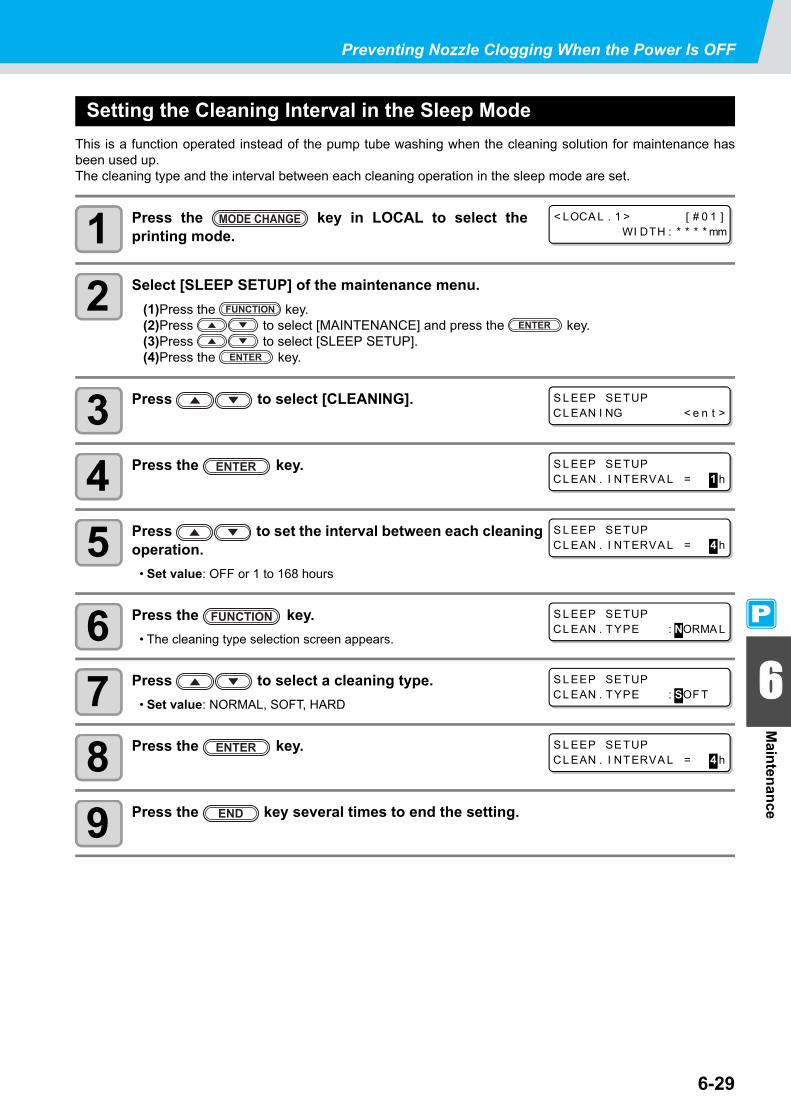
Preventing Nozzle Clogging When the Power Is OFF
6-29
6
Maintenance
Setting the Cleaning Interval in the Sleep ModeThis is a function operated instead of the pump tube washing when the cleaning solution for maintenance hasbeen used up.The cleaning type and the interval between each cleaning operation in the sleep mode are set.
1 Press the key in LOCAL to select theprinting mode.
2 Select [SLEEP SETUP] of the maintenance menu.(1)Press the key.(2)Press to select [MAINTENANCE] and press the key.(3)Press to select [SLEEP SETUP].(4)Press the key.
3 Press to select [CLEANING].
4 Press the key.
5 Press to set the interval between each cleaning operation.
• Set value: OFF or 1 to 168 hours
6 Press the key.• The cleaning type selection screen appears.
7 Press to select a cleaning type.• Set value: NORMAL, SOFT, HARD
8 Press the key.
9 Press the key several times to end the setting.
< LOCA L . 1 > [ # 0 1 ]WI DTH : * * * * mm
S L EEP SETUPCL EAN I NG < e n t >
S L EEP SETUPCL EAN . I NTERVA L = 1 h
S L EEP SETUPCL EAN . I NTERVA L = 4 h
S L EEP SETUPCL EAN . TYPE : NORMA L
S L EEP SETUPCL EAN . TYPE : SOF T
S L EEP SETUPCL EAN . I NTERVA L = 4 h

6-30
Setting Regular OperationsVarious regular operations are performed with the power ON to prevent problems, such as ink coagulation, fromoccurring (Regular settings). For the regular settings, the following items can be set:
Default value
Set Item Set Value Overview
ROUTINE WIPING
SCAN COUNT 0 to 9,990 timesWhen the set number of times scanning is performed has beenreached during a printing operation, the nozzle face is wipedand dew condensation is removed.
TEMP. Difference 0 ~ 60°C
When the difference between the set temperature of the printheater and the ambient temperature has exceeded a specifiedtemperature during a printing operation, the nozzle face is wipedand dew condensation is removed.
REFRESH
OFF/1 to 168hours
The interval between each refreshing operation is set.
PUMP TUBE WASHThe interval between each PUMP tube washing operation is set.
CLEANINGThe interval between each cleaning operation is set.
Ink Type Refreshing PUMP Tube Washing CleaningBS* 4 hours 48 hours OFF
• When the message on the right is displayed, the operations otherthan [ROUTINE WIPING] in the regular settings are not performed.Perform the operations described on P.6-39 as necessary.
• When you turn off the power switch on the front side of the machine,check the state of the waste ink tank.
• Even if [!RTN] is displayed, the connection unit automatically switches to the printer unit and starts the regular operation when the machine is left unused for a certain period of time.
< LOCA L . 1 > [ # 0 1 ]! WASTE TANK
< LOCA L . C > ! RTN [ # 0 1 ]CUT 1 ( 3 0 / 6 0 / 0 . 3 0 )

6-31
Setting Regular Operations
6 6
Maintenance
Setting the Regular Wiping Operation during a Printing OperationWhen the set number of times scanning is performed has been reached during a printing operation, a wipingoperation is performed automatically to prevent ink dew condensation on the nozzle face.
In the following cases, ink splashing, ink dripping or nozzle missing may occur during a printing operation.It is recommended that the regular wiping operation be set to always maintain a good printing state.
• When the print heater has been set at a high temperature• When a relatively large value (high density, two coats of ink, etc.) has been set to the amount of ejected ink
The cause of the ink splashing, ink dripping or nozzle missing is that the ink printed immediately after ink ejectionis heated by the print heater, which causes evaporated solvent to condense on the nozzle face.In addition, the larger the difference between the set temperature of the print heater and the ambient temperatureis, the more easily the evaporated solvent can condense.
1 Press the key in LOCAL to select theprinting mode.
2 Select [ROUTINE SETUP] of the maintenance menu.(1)Press the key.(2)Press to select [MAINTENANCE] and press the key.(3)Press to select [ROUTINE SETUP].
3 Press the key.
4 Press the key.
5 Press the key.
6 Press to set the number of times scanning is performed.
• Set value: 0 to 9,990 times• The set value should be 30 to 50 times when the heater temperature has been set at a high one (around
50°C) or when the amount of ejected ink is large, for example, due to two coats of ink.
7 Press the key.
8 Press .• The temperature difference setting screen appears.
9 Press the key.
< LOCA L . 1 > [ # 0 1 ]WI DTH : * * * * mm
ROUT I NE SETUPROUT I NE WI P I NG < e n t >
ROUT I NE WI P I NGSCAN COUNT < e n t >
ROUT I NE WI P I NGSCAN COUNT = 5 0
ROUT I NE WI P I NGSCAN COUNT = 4 0
ROUT I NE WI P I NGSCAN COUNT < e n t >
ROUT I NE WI P I NGTEMP . d i f f e r e n c e < e n t >
ROUT I NE WI P I NGTEMP . D i f f e r e n c e = 2 0 ° C

6-32
10 Press to set temperature difference (0 to 60°C).
• When the set temperature of the print heater is higher than the ambient temperature and the differencebetween the two exceeds a specified temperature, the regular wiping function is activated.
11 Press the key.
12 Press the key several times to end the setting.
ROUT I NE WI P I NGTEMP . D i f f e r e n c e = 2 0 ° C
ROUT I NE WI P I NGTEMP . d i f f e r e n c e < e n t >

6-33
Setting Regular Operations
6 6
Maintenance
Setting the Refreshing Interval in the Standby ModeThe interval between each refreshing operation is set.
1 Press the key in LOCAL to select theprinting mode.
2 Select [ROUTINE SETUP] of the maintenance menu.(1)Press the key.(2)Press to select [MAINTENANCE] and press the key.(3)Press to select [ROUTINE SETUP].(4)Press the key.
3 Press to select [REFRESH].
4 Press the key.
5 Press to set the interval between each refreshing operation.
• Set value: OFF or 1 to 168 hours
6 Press the key.
7 Press the key several times to end the setting.
< LOCA L . 1 > [ # 0 1 ]WI DTH : * * * * mm
ROUT I NE SETUPREFRESH < e n t >
ROUT I NE SETUPREFRESH i n t e r v a l = 1 h
ROUT I NE SETUPREFRESH i n t e r v a l = 1 0 h
ROUT I NE SETUPREFRESH < e n t >

6-34
Setting the Interval between Each PUMP Tube Washing Operation in the Standby ModeThe PUMP tube is washed regularly to prevent nozzle clogging caused by ink coagulation in the tube.
1 Press the key in LOCAL to select theprinting mode.
2 Select [ROUTINE SETUP] of the maintenance menu.(1)Press the key.(2)Press to select [MAINTENANCE] and press the key.(3)Press to select [ROUTINE SETUP].(4)Press the key.
3 Press to select [PUMP TUBE WASH].
4 Press the key.
5 Press to set the interval between each PUMP tube washing operation.
• Set value: OFF or 1 to 168 hours
6 Press the key.
7 Press the key several times to end the setting.
• This function can be performed only when the states shown by the screens below are maintained.
• When the machine has not been filled with cleaning solution, thescreen on the right appears in Step 5. Fill the machine withcleaning solution ( P.6-10) and perform the operations in Step 1and later.
• If the cleaning solution is not set, it does not work.* Set thecleaning solution.*For [!Wash Liquid END], it works to use up the cleaning solution, however, replace early.
< LOCA L . 1 > [ # 0 1 ] * REMOTE . 1 * [ # 0 1 ]0 . 0 0m
LOCAL REMOTE
< LOCA L . 1 > [ # 0 1 ]WI DTH : * * * * mm
ROUT I NE SETUPPUMP TUBE WASH < e n t >
ROUT I NE SETUPWASH I NTERVA L = 1 h
ROUT I NE SETUPWASH I NTERVA L = 4 h
ROUT I NE SETUPPUMP TUBE WASH < e n t >
* Wa s h L i q u i d U N - F I L L *
< LOCA L . C> ! WSH [ # 0 1 ]CUT 1 ( 3 0 / 6 0 / 0 . 3 0 )
< LOCA L . 1 > [ # 0 1 ]! Wa s h L i q u i dCa r t . NONE
or

Setting Regular Operations
6-35
6
Maintenance
Setting the Cleaning Interval in the Standby ModeThis is a function operated instead of the PUMP tube washing when the cleaning solution for maintenance hasbeen used up.The cleaning type and the interval between each cleaning operation in the standby mode are set.
1 Press the key in LOCAL to select theprinting mode.
2 Select [ROUTINE SETUP] of the maintenance menu.(1)Press the key.(2)Press to select [MAINTENANCE] and press the key.(3)Press to select [ROUTINE SETUP].(4)Press the key.
3 Press to select [CLEANING].
4 Press the key.
5 Press to set the interval between each cleaning operation.
• Set value: OFF or 1 to 168 hours
6 Press the key.• The cleaning type selection screen appears.
7 Press to select a cleaning type.• Set value: NORMAL, SOFT, HARD
8 Press the key.
9 Press the key several times to end the setting.
• This function is not performed when ink-related errors, such as "NEAR END" and "INK END", havebeen occurring.
• While this function is performed, the screen shows the progress that is the same as that of Headcleaning and no key operation can be performed. ( P.2-40 "Perform head cleaning depending on thetest printing result")
• This function can be performed only when the states shown by the screens below are maintained.
< LOCA L . 1 > [ # 0 1 ] * REMOTE . 1 * [ # 0 1 ]0 . 0 0m
LOCAL REMOTE
< LOCA L . 1 > [ # 0 1 ]WI DTH : * * * * mm
ROUT I NE SETUPCL EAN I NG < e n t >
ROUT I NE SETUPCL EAN . I NTERVA L = 1 h
ROUT I NE SETUPCL EAN . I NTERVA L = 4 h
ROUT I NE SETUPCL EAN . TYPE : NORMA L
ROUT I NE SETUPCL EAN . TYPE : SOF T
ROUT I NE SETUPCL EAN . I NTERVA L = 4 h

6-36
Other Maintenance FunctionsChanging the Time When a Warning about Wiper Replacement Is Issued
The wiper is consumable. The head can easily become dirty in a dusty environment.In addition, the head cannot be cleaned adequately with a bent or worn wiper used. Wiper levels can be set sothat a warning about wiper replacement is issued earlier than the standard according to the operatingenvironment.
1 Press the key in LOCAL to select theprinting mode.
2 Select [WIPER LEVEL] of the maintenance menu.(1)Press the key.(2)Press to select [MAINTENANCE] and press the key.(3)Press to select [WIPER LEVEL].
3 Press the key.
4 Press to set a wiper level.• Set value: 1/10 to 10/10
5 Press the key.
6 Press the key several times to end the setting.
Set Value Overview
1/10 ~ 10/10The time when a warning about wiper replacement is issued is set.As the value becomes smaller, a warning about wiper replacement is displayed earlier.
Normal wiper Deformed wiper
< LOCA L . 1 > [ # 0 1 ]WI DTH : * * * * mm
WI PER L EVE LL EVE L : 1 0 / 1 0
WI PER L EVE LL EVE L : 9 / 1 0
MA I NTENANCEWI PER L EVE L < e n t >

6-37
Other Maintenance Functions
6 6
Maintenance
Setting the Display of Media ResidualWhether the screen displays the remaining amount of a medium is set.
1 Press the key in LOCAL to select theprinting mode.
2 Select [MEDIA RESIDUAL] of the maintenance menu.(1)Press the key.(2)Press to select [MAINTENANCE] and press the key.(3)Press to select [MEDIA RESIDUAL].
3 Press the key.
4 Press to select ON/OFF.
5 Press the key.
6 Press the key several times to end the setting.
When "Remaining amount of a medium to display" is set to ON,
the remaining amount of a medium is displayed in the remote mode.(However, when a leaf medium is used, the length of the medium to be printedis displayed.)
When "Remaining amount of a medium to display" is set to OFF, the remaining amount of a medium is not displayed in the remote mode.
• The amount of a medium that has been fed by the printing and jog keys is reflected in the remainingamount of a medium.
• The length of a medium (initial value of the remaining amount) is entered when a roll medium isdetected. ( P.2-29)
• The setting configured here does not become effective unless media detection is performed after thesetting has been complete.
< LOCA L . 1 > [ # 0 1 ]WI DTH : * * * * mm
MED I A RES I DUA LSETUP : ON
MED I A RES I DUA LSETUP : OF F
MA I NTENANCEMED I A RES I DUA L < e n t >

6-38
Printing the Remaining Amount of a MediumThe present remaining amount of a medium can be printed.
1 In LOCAL, Press .• LOCAL changes to the origin setting mode.
2 Press to set the origin to a desired position.• Move the carriage and medium with and set the
origin.• When you do not change the origin, do not press
and proceed to Step 3.
• When you press the key here, the origin is changed, andthe screen returns to LOCAL.
3 Press the key.• When you press ,
the screen returns to Step 2.• When you press the key, the screen returns to LOCAL.
4 Press the key.• The remaining amount of a medium starts to be printed.• When the printing has been completed, the screen returns to LOCAL.
• Set "Remaining amount of a medium to display" to "ON".• When you replace the medium you use now with another, it is recommended that you print the
remaining amount of the medium on it. With the remaining amount of a medium having been printedbeforehand, when you use the replaced medium again, you can enter an accurate value in the screenfor entering the remaining amount of a medium ( P.2-29) that appears after media detection.
• When the remaining amount of a medium has been printed with the origin changed, the origin set hereis effective even when subsequent data are printed.
OR I G I N SETUP0 . 0 - - - -
OR I G I N SETUP0 . 0 - - - -
Origin position(length)
Origin position(width)
MED I A RES I DUA L PR I NT< ENT >

6-39
Other Maintenance Functions
6 6
Maintenance
If a Waste Ink Tank Confirmation Message AppearsInk used in head cleaning, etc. is stored in the waste ink tank on the lower right side of the machine. Thismachine counts the accumulated amount of discharged ink. When that reaches a specified amount, the machinedisplays a confirmation message. (When this message is displayed, consider the replacement of the wasteink tank.)
If a Message Is Displayed, for Example, When the Machine Is Supplied with InkWhen functions that use the waste ink tank, such as ink-supplying, head cleaning, and PUMP tube washing, areperformed, a message that requests you to confirm the state of the waste ink tank may be displayed, dependingon the state of the tank.
When the waste ink tank is almost full:
The message on the right is displayed.
1 Check the state of the waste ink tank.When the waste ink tank is almost full:(1)Replace the waste ink tank with another. ( P.6-41) (2)Press the key to select "Exchange". (The amount of discharged ink is reset.)
When the waste ink tank still has a capacity for waste ink:(1)Press to select "Continue". (The amount of discharged ink is not reset.)
• In this case, returning to LOCAL will display the message of P. 6-39 "Confirmation Message inLOCAL".
When the waste ink tank is completely full:
The message on the right is displayed.
1 Replace the waste ink tank with another ( P.6-41) and press the key.• The amount of discharged ink is reset.
Confirmation Message in LOCAL
The message on the right is displayed.
1 Check the state of the waste ink tank and replace it with another as necessary. ( P.6-41)
• When you have selected "Exchange" for "almost full" or "completely full" in the above operation, makesure to replace the waste ink tank. ( P.6-41) When you use the machine without replacing the wasteink tank, waste ink may overflow from the tank before a confirmation message is displayed.
• This machine does not count the accumulated amount of waste ink discharged when theST.MAINTENANCE (NOZZLE WASH, PUMP TUBE WASH, and COSTODY WASH (firmware Ver.2.20or older)) are performed. Before performing these functions, make sure to check the state of the wasteink tank.
Co n f i r m a wa s t e t a n kCo n t i n u e < > E x c h a n g e
Co n f i r m a wa s t e t a n kE x c h a n g e : e n t
< LOCA L . 1 > [ # 0 1 ]! WASTE TANK

6-40
When You Do Not Want the Confirmation Message of the Waste Ink Tank to Be Displayed You can configure the setting so that the confirmation message of the waste ink tank is not displayed.
1 Press the key in LOCAL to select theprinting mode.
2 Select [Waste Ink Warning] of the machine setting menu.(1)Press the key.(2)Press to select [MACHINE SETUP] and press the key.(3)Press to select [Waste Ink Warning].(4)Press the key.
3 Press to select OFF.
4 Press the key.
5 Press the key several times to end the setting.
• When you set Waste ink warning to "OFF", the confirmation message is not displayed. Make sure tovisually check the amount of ink remaining in the waste ink tank.
< LOCA L . 1 > [ # 0 1 ]WI DTH : * * * * mm
Wa s t e I n kWa r n i n gSETUP : OF F
MACH I NE SETUPWa s t e I n kWa r n i n g < e n t >

6-41
Other Maintenance Functions
6 6
Maintenance
Replacing the Waste Ink Tank with AnotherWhen the message on the right has been displayed, check the state ofthe waste ink tank immediately and replace the tank as necessary.
1 Remove the waste ink tank guard.(1)Lift the waste ink tank guard and unlock it.(2)Open the waste ink tank guard to your side.
2 Hold the grip of the waste ink tank and remove the tank by pulling it to your side.
• Attach the cap to the removed waste ink tank.
3 Replace the waste ink tank with another.(1)Prepare a new waste ink tank (SPC-0117).(2)Hold the grip of the waste ink tank and insert the tank.
< LOCA L . 1 > [ # 0 1 ]! WASTE TANK
Waste ink guard
Lift and pull it.
Cap
Accumulated waste ink
New waste ink tank

Other Maintenance Functions
6-42
4 Close the waste ink tank guard.• Align the protrusion of the waste ink tank guard with the hole of the main body and lock the tank.
v
5 Press the key in LOCAL to select the printing mode.
6 Select [Ink Tank Replace] of the maintenance menu.(1)Press the key.(2)Press to select [MAINTENANCE] and press the key.(3)Press to select [Ink Tank Replace].
7 Press the key.
8 Press the key.• The amount of discharged ink controlled by this machine is reset, and the confirmation message is
canceled.
9 Press the key several times to end the setting.
Hole Protrusion
< LOCA L . 1 > [ # 0 1 ]WI DTH : * * * * mm
I n k T a n k Re p l a c eEXCHANGE : e n t

6-43
6
Maintenance
Replacing the Cutter BladeThe medium cutter blade is consumable. When the cutter blade gets dull, replace it with a new one (SPA-0107).
1 Press the key in LOCAL to select cuttingmode.
2 Press the key.
3 Press to select [MAINTENANCE].
4 Press the key.
5 Press to select [TOOL REPLACE].
6 Press the key.
7 Press the key.• The cutter unit moves to the left end of the machine.
• The blade is sharp. Be careful not to hurt yourself or anyone else.• Store the cutter blade in a place that is out of the reach of children. In addition, dispose of used cutter
blades according to regional laws and regulations.
• When replacing the cutter blade, it is recommended to place a sheet of paper under the cutter blade.This will help pick up the cutter blade if it drops.
< LOCA L . C > [ # 0 1 ]CUT 1 ( 3 0 / 6 0 / 0 . 3 0 )
FUNCT I ON CSETUP < ENT >
FUNCT I ON CMA I NTENANCE < ENT >
MA I NTENANCEMARK SENSOR < e n t >
MA I NTENANCETOOL REP L ACE < e n t >
TOOL REP L ACEACT I ON : e n t

Replacing the Cutter Blade
6-44
8 Replace the cutter unit by the carriage.• Now the cutter unit can be moved manually. Move the cutter unit to the position where you can assure
easy access, and then replace the blade edge.
(1)Loosen the screw of the cutter unit.(2)Remove the cutter unit.(3)Mount a new cutter unit.(4)Fasten the screw of the cutter unit to secure the cutter unit.
9 When replacement is finished, press the key.• The screen returns to LOCAL.
Screw
Cutter unit
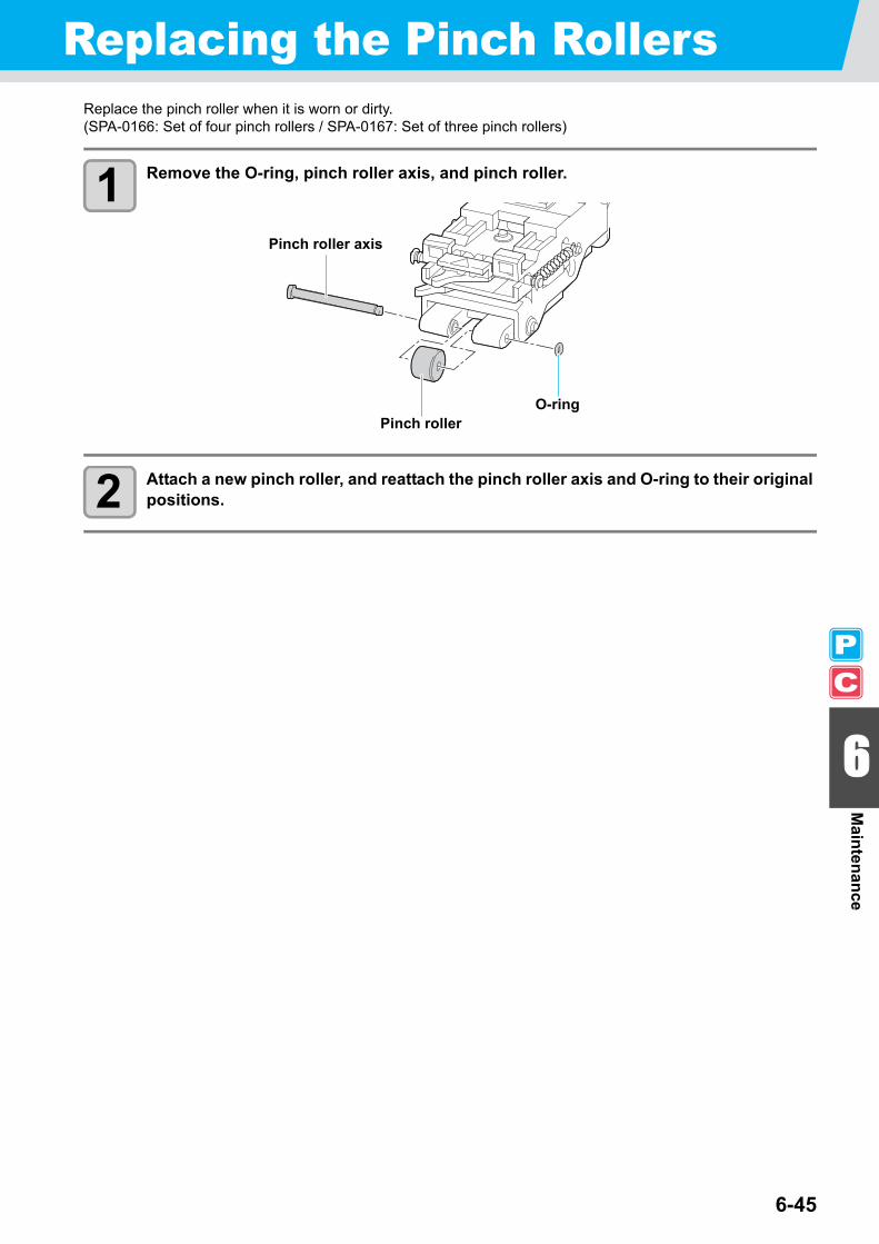
6-45
6
Maintenance
Replacing the Pinch RollersReplace the pinch roller when it is worn or dirty.(SPA-0166: Set of four pinch rollers / SPA-0167: Set of three pinch rollers)
1 Remove the O-ring, pinch roller axis, and pinch roller.
2 Attach a new pinch roller, and reattach the pinch roller axis and O-ring to their original positions.
Pinch roller axis
O-ringPinch roller

6-46
Replacing a Cutter Blade Not Included in the AccessoriesThis section describes how to replace the cutter holder (Swivel cutter holder : SPA-0090) and the cutter (Swivelblade : SPB-0030) that are sold separately.
1 Rotate the cap from which a blade comes out andremove the cutter.
2 Replace the cutter with a new one, using tweezers.
3 Adjust the length of the cutter blade that comes out from the cap.
• When you rotate the adjustment knob in the direction of an arrow, acutter blade emerges. (0.5 mm per rotation)
Cutter holder
Cutter
Cap
Cutter blade
Adjustment knob

This chapter
describes the corrective measures to be taken for a phenomenon suspected to betrouble and the procedures to clear the error number displayed on the LCD.
Troubleshooting ............................................................................ 7-2Image Quality Is Poor ......................................................................7-4Nozzle Is Clogged ...........................................................................7-4Ink Cartridge Warning Appears .......................................................7-5
Warning/Error Messages .............................................................. 7-7Warning Messages ..........................................................................7-7Error Messages .............................................................................7-10
Chapter 7Troubleshooting

7-2
TroubleshootingTake the appropriate actions as described below before taking the trouble as a failure. If the problem is still notsolved after troubleshooting, contact your distributor or our service office.
Failure phenomenon Cause SolutionPower does not turn ON. The power cable of the machine is not
connected securely.Securely connect the power cable of the machine to the outlet.
The main switch is not ON. Turn ON the main switch.The power switch located on the front of machine is not ON.
Turn ON the power switch on the front of the machine.
Printing/cutting (printing with apen) does not start.
The interface cable is not connected securely.
Securely connect the interface cable.
The interface cable is not correct. Use a USB2.0 Hi-Speed-compliant cable.The message indicating that the ink has run out is displayed.
Replace the ink cartridge with a new one.
The host computer setting (machine model, etc.) is wrong.
Check the host computer setting.
The USB driver is not installed. Install the USB driver included with the machine.
Medium gets jammed.Medium is soiled.
A medium other than those recommended by MIMAKI is used.
Use the recommended medium.
Medium is curled. Avoid using a medium with curls.The end of the medium is bent. Avoid using any medium with bent ends.The medium is hanging down along the platen.
Use a take-up device or re-load the medium on the machine.
[HEAT] or [CONSTANT] LEDdoes not light up.
The power to the machine is not ON. Turn ON the power to the machine.The heater temperature setting is not effective.
Set the heater temperature higher than room temperature.
An error occurs in the machinewhen the host computer sendsdata to the machine.
Command settings are wrong. Use the application included with the machine.
Machine model setting is wrong. Correct the machine model setting to [CJV30BS] on the application software.
Cutting produces a perforationrather than a clean cut.
Screw for the tool holder is loose. Tighten up the screw.The cutter blade protrudes excessively. Adjust the protrusion of the blade properly.The tool condition is set to [HALF]. Set the tool condition to [CUT1] to [CUT3].The blade is chipped or worn out. Replace the blade with a new one.The blade does not rotate smoothly. Replace the holder with a new one.
Slippage of medium arises incutting.
The pinch rollers and grid rollers fail to securely retain the medium in position.
Check the position of the pinch rollers and grid roller and adjust them so that they securely retain the medium in position.Increase the number of pinch rollers.
The pinch roller pressure is not properly selected.
Select the proper pinch roller pressure. ( P.4-2)
There is a slack in the roll medium so the medium fed meanders or skews.
Remove the slack in the roll medium and straighten the right and left end faces of the roll when loading the roll medium on the machine. Then, start feeding the medium.

7-3
Troubleshooting
7
Troubleshooting
Failure phenomenon Cause SolutionSlippage of medium arises in cutting.
The medium was bent and came off the backing paper and thus there are air bubbles between the medium and the backing paper.
When a long leaf medium is to be cut, take care not to bend the medium while feeding or cutting it and do not put any extra load on the medium.When a long leaf medium is to be cut, provide a sufficient space for working in the direction of medium feeding.Front: 1.5 m or moreRear: 1.5 m or more
The setting direction of the medium and the direction specified on the data do not agree with each other.
Correct the medium setting or data setting.
The medium comes in contact with the floor surface.
Decrease the cutting speed (SPEED) to reduce the load on the medium when it comes in contact with the floor surface.
The side margins of the medium beside the pinch rollers are not enough.
Provide a side margin of 20 mm or more on each side of the medium beside the pinch rollers.
The setting of offset X and offset Y of"Setting Register Mark Detection" is notcorrect.
Correct the offset value in concert withmisalignment. ( P.4-11)
The tool is dragged during operation.
An unexpected cutter imprint remains on the medium.
The medium is warped. Load the medium on the machine so that the medium is not warped.
The tool does not move up/down successfully.
Turn the power OFF and try to lift/lower the tool holder by hand.If the tool holder does not move up but remains in the lower position, contact your distributor or our service office.
An extremely thick medium is used. Use a medium meeting the specifications.Some parts remain uncut. Low pressure on the cutter blade. Increase the value of
“ADJ-PRS OFFSET”. ( P.4-36)Increase the cutter pressure and performtest cutting again. ( P.2-37)Set the over cutting. ( P.4-36)
Register mark cannot be detected.
The position of the register mark sensorand the light pointer is not the same.
Adjust the position of the light pointer.( P.4-20)
The sensitivity of the register marksensor is low.
Adjust the sensitivity of the register marksensor. ( P.4-21)
There is a part remaining uncutwhen cutting medium.
Both ends of the medium stays awayfrom the position of pinch rollers locatedat both ends.
Set the pinch roller of both ends so thatthey are within the range of 10cm frommedium left end and 2cm from mediumright end. ( P.2-17)

7-4
Image Quality Is PoorThis section describes the corrective actions to be taken in case the image quality is not satisfactory. Takeappropriate measures to remedy the problems with image quality. If the remedy does not work, contact yourdistributor or our service office.
Nozzle Is CloggedWhen nozzle clogging is not dissolved even after cleaning the head referring to P.2-36, make sure of thefollowing operations.
Fill ink by executing the operations of P.6-21.
Following the procedures described in P.6-22, perform DISCHARGE & WASH.
Failure phenomenon Solution
White lines/blur/dark stripes (in thedirection the heads travel)
(1) Execute head cleaning. P.2-36(2) Perform maintenance of the inside of the station. P.6-5(3) Execute the [Media correction] function. P.3-8(4) If any pieces of paper or dust is attached on the medium holder
or other paths of the head, remove it.
Characters are double or triple printed in the media feed direction.
(1) Execute the [Media correction] function. P.3-8
Disagreement in print positions between outward trip and homeward trip.
(1) Execute the [Dot position correction] function. P.3-10
Ink drops falling on the medium during printing.
(1) Execute the wiper cleaning. P.6-6(2) Execute the ink cap cleaning. P.6-6(3) Execute the head cleaning [Normal]. P.2-36(4) When the phenomenon is not improved, set the regular wiping
operation. P.6-31

7-5
Troubleshooting
7
Troubleshooting
Ink Cartridge Warning AppearsIf trouble with an ink cartridge is detected, a warning message appears.Printing, cleaning, and all the other operations that use ink become disabled if warning occurs.In this case, replace the ink cartridge immediately.
Displaying the Description of Ink Cartridge TroubleYou can check the details of the cartridge error with the following operations. ( P.7-6)
1 Press the key in LOCAL.
2 Press the key.
• When two or more cartridge troubles occur, warnings can be displayed in turn by pressing .
• Press or to return to the display of the remaining amount of ink.
• Once cartridge trouble is displayed, do not leave the ink cartridge for a long time without replacing it;otherwise, the machine will lose the nozzle clogging prevention function.If nozzles are clogged, the machine must be repaired by our service engineer.
BS * I NK MMCCYYKKREMA I N 3 4 5 6 7 8 9 9
NON - OR I G I NA L I NK- - - C - - - -
Indicates that the cartridge of cyan (C) has some
abnormality.

Troubleshooting
7-6
Messages and Solutions
Message Cause Solution
The ink of the ink cartridge has been nearlyused up.
Replace the cartridge generating the warningwith a new one.
The ink of the ink cartridge has been completelyused up.
Replace the cartridge generating the warningwith a new one.
The ink cartridge is not our genuine product. Replace the cartridge generating the warningwith our genuine product.
The IC chip of the ink cartridge cannot be readnormally.
Remove the cartridge generating the warningonce and install it again.If the same warning message still appears,contact our service office or the distributor in yourregion.
The ink of the ink cartridge is different in typefrom the ink currently supplied.
Check the ink type of the cartridge generating thewarning.
The ink of the ink cartridge is different in colorfrom the ink currently supplied.
Check the ink color of the cartridge generatingthe warning.
There is trouble with an installed ink cartridge. Check the cartridge generating the warning.
An ink cartridge has not been installed in theslot.
Install an appropriate cartridge in the slotgenerating the warning.
The specified expiration date of an ink cartridgehas passed.
Replace the cartridge generating the warningwith a new one.The cartridge may be used until one month afterthe specified expiration date.
The expiration date of an ink cartridge haselapsed (one month has passed after thespecified expiration date).
The red LED blinks. Replace the cartridgegenerating the warning with a new one.The cartridge may be used until two months afterthe specified expiration date.
The expiration date of an ink cartridge haselapsed (two months have passed after thespecified expiration date).
Replace the cartridge generating the warningwith a new one.
The remaining amount of the ink in an inkcartridge is zero.
Replace the cartridge generating the warningwith a new one.
I N K N E A R E N DMMC C - - - -
I N K E N D- - - - Y Y K K
NON - OR I G I N A L I N K- - - - Y Y K K
WRONG I N K I C- - - - Y Y K K
K i n d o f I N K- - - - - - - -
C o l o r o f I N K- - - - - - - -
WRONG C A R T R I DG E- - - - - - - -
NO C A R T R I DG E- - - - - - - -
E x p i r a t i o n- - - - - - - -
E x p i r a t i o n : 1 MON T H- - - - - - - -
E x p i r a t i o n : 2 MON T H- - - - - - - -
I N K R EMA I N Z E RO- - - - - - - -

7-7
7
Troubleshooting
Warning/Error MessagesIf some trouble occurs, the buzzer sounds and the display shows a corresponding error message.Take appropriate measures to remedy the displayed error.
Warning Messages
Message Cause Solution
Medium is not set. Set the medium.
The end of the life of the internal clock battery isdetected.
Contact our service office or the distributor inyour region.
Time to replace the wiper in the capping stationwith a new one has come.(The wiping count has reached the specifiedvalue.)
Replace the wiper with a new one.( P.6-8)
When the power supply has been kept turningOFF for 72 hours or longer, sleep refresh orcleaning was not performed.
Perform the test printing and check the nozzlestatus.If the power supply has been kept turning OFFfor a long time, the sleep operation must beperformed. ( P.6-26)
A heater is disconnected.(This example shows that the preheater isdisconnected.) Contact our service office or the distributor in
your region.The thermistor of a heater is defective.(This example shows that the thermistor of pre-heater is defective.)
Ink for one supply path has been nearly usedup.
Replace the cartridge for the supply pathcorresponding to the indicated color.You can print without replacing the cartridge(until "No ink" is displayed). However, themachine returns to LOCAL each time when theprinting of one file is completed.
Ink for one supply path has been completelyused up.
Replace the cartridge for the supply pathcorresponding to the indicated color.
Ink for one supply path is not set.Or improper ink is set.
Replace or set the cartridge for the supply pathcorresponding to the indicated color.Refer to P. 7-5 "Ink Cartridge Warning Appears"to check the details of the failure, and then fix theproblem following the applicable procedure.
Ink near end was detected right after thecartridge with much remaining amount of inkhas been inserted.
Pull out the inserted cartridge and insert it again.If the message will be displayed again, contact adistributor in your district or our office to call forservice.
600cc ink is low. Remove and weigh the 600cc cartridge, then setit again. ( P.3-38)
600cc ink is low. Remove and weigh the 600cc cartridge, then setit again. ( P.3-38)
* * NO ME D I A * *
! E X C H A NG E B A T T E R Y
< L OC A L . 1 > [ # 0 1 ]! R e p l a c e a W I P E R
< L OC A L . 1 > [ # 0 1 ]! D o T E S T P R I N T
P R E P R T P O S TB R E A K * * ° C * * ° C
P R E P R T P O S TT H E RM * * ° C * * ° C
< L OC A L . 1 > [ # 0 1 ]N E A R E N D MMC C - - - -
* R EMO T E . 1 * [ # 0 1 ]N E A R E N D MMC C - - - -
< L OC A L . 1 > [ # 0 1 ]I N K E N D - - - - Y Y K K
* R EMO T E . 1 * [ # 0 1 ]I N K E N D - - - - Y Y K K
< L OC A L . 1 > [ # 0 1 ]! C A R T R I DG E - - - - Y Y K K
* R EMO T E . 1 * [ # 0 1 ]! C A R T R I DG E - - - - Y Y K K
< L OC A L . 1 > [ # 0 1 ]R E I N S E R T C A R T R I DG E
< L OC A L . 1 > [ # 0 1 ]I n k L e v e l - - - - Y - K -
* R EMO T E . 1 * [ # 0 1 ]I n k L e v e l - - - - Y - K -
I N K L E V E L ( 6 0 0 c c )- - - - - - - -

7-8
Message Cause Solution
There is a problem with the installed ink cartridges.
Check the warning details in the guidance function. ( P.7-5)
There are the following problems with the cleaning solution:The cleaning solution is not set.Something other than the cleaning solution is set.The cleaning solution is ended.
Replace the cleaning solution.
As the connection unit is not connected to theprint head, regular operations cannot beexecuted.
Start the origin setting in the print mode, andswitch the connection unit, or execure theappropriate regular operations manually.
The waste ink tank is nearly full.Replace the waste ink tank, and then execute[MAINTENANCE]-[Ink Tank Replace].( P.6-41)
The cleaning liquid cartridge is empty. Replace the cleaning solution cartridge with anew one.
The cleaning liquid cartridge has not beeninstalled. Install the cleaning solution cartridge.
There is trouble with the cleaning liquidcartridge. Install the cleaning solution cartridge.
Cleaning solution has not been supplied.
Supply the cleaning solution.Execute [MAINTENANCE]-[HD.MAINTENANCE]-[FILL UP INK]. ( P.6-21)
** OFFSCALE **
The cutting data exceeds the effective cuttingarea.Or the machine has stopped after cutting themedium up to its end normally.
Use a larger medium, decrease the amount ofdata, or execute the divided cutting function.This warning may occur depending on the setvalue of the P/C origin offset ( P.4-32).
** END COPY **The plotter has terminated copying aftercompletion of one sheet copying, since the datareceived contains the origin updating command.
The plural sheets cutting function is disabled.To perform plural sheets cutting, change thesetting back to enable the function on the hostcomputer.
** DIVISION ** 5s
The machine has finished the cuttingcorresponding to a division of the data thatexceeds the medium width, using the divisioncut function, and is now waiting for the receipt ofthe next data.
If the machine does not receive any data fromthe host computer within ten seconds, it willrecognize that the data has ended.Then, the machine will perform the frame cuttingand mark cutting and enter LOCAL.
** END DIVISION **
This message appears in any of the followingcases:The medium width is 1 cm or less.The sample cutting data exceeds the mediumwidth.The two-point axis alignment is set to ON.Register marks have already been detected.
Division cut is disabled.
< L OC A L . 1 > ! C A R [ # 0 1 ]
* R EMO T E . 1 * ! C A R [ # 0 1 ]
< L OC A L . 1 > ! WS H [ # 0 1 ]
* R EMO T E . 1 * ! WS H [ # 0 1 ]
< L OC A L . 1 > ! R T N [ # 0 1 ]
* R EMO T E . 1 * ! R T N [ # 0 1 ]
< L OC A L . 1 > ! T N K [ # 0 1 ]
* R EMO T E . 1 * ! T N K [ # 0 1 ]
< L OC A L . 1 > [ # 0 1 ]! WA S T E T A N K
< L OC A L . 1 > [ # 0 1 ]! Wa s h L i q u i d E N D
< L OC A L . 1 > [ # 0 1 ]! w a s h L i q u i d C a r t . NON
< L OC A L . 1 > [ # 0 1 ]! WRONG WA S H C A R T .
* * Wa s h i n g l i q u i d * *

7-9
Warning/Error Messages
7
Troubleshooting
Message Cause Solution
COPY SKIP A register mark cannot be detected duringcontinuous copying. (One pattern is skipped.)
There is no problem if the marks are successfullydetected after skipping one pattern.If marks cannot be detected continuously by fivepatterns or more, [ERROR 36-C MARKDETECT] ( P.7-12) is displayed.
MEDIA SKEW <ENT> Sheet misalignment exceeds the setting lengthof skew check ( P.4-14).
Set the sheet again and press the key.
PAUSE REM/ENDThe plotter is holding the register mark detecting operation, since the key has been pressed during the detection process.
Press the key to resume the mark detection.Or press the key to end the operation.
MEDIA EXCHANGEThe machine is waiting for the medium to be replaced during continuous copying in the leaf media mode.
Replace the leaf sheet (cut sheet) with a new one, and resume continuous copying.
MEDIA END REM/END
End of the medium is detected while detecting a register mark or cutting roll medium.
Cutting cannot be continued, since roll medium has ended.Press the key and replace it with new medium.
The medium is lifted. Fix the lifting of the sheet and press the key to resume cutting.
The back of the machine is exposed to intense light.
Turn the machine around so as not to exposed it to the light, and press the key to resume cutting.

7-10
Error MessagesWhen an error message is displayed, eliminate the error according to the chart below.If the same error message appears again, contact your distributor or our service office.
Error messages Cause Solution
An error occurred in the circuit board system. (ROM)
Turn OFF the power to the machine and turn it ON again after a while.If the same error message appears again, contact our service office or the distributor in your region.
An error occurred in the circuit board system. (RAM)
An error occurred in the circuit board system.(Power supply voltage +5 V)
An error occurred in the circuit board system.(Power supply voltage +24 V)
An error occurred in the circuit board system.(Power supply voltage +42 V)
An error occurred in the circuit board system. (Parameter ROM)
An error occurred in the circuit board system. (SDRAM)
A connection error in the heads was detected.(Abnormal temperature was detected.)
A connection error in the heads was detected.(Abnormal voltage was detected.)
An error occurred in detecting the linear encoder. (Unable to count)
An error occurred in detecting the linear encoder.(Error in the mounting direction)
An error occurred in detecting the linear encoder.(Read-out count error)
An error occurred in the circuit board system.(FPGA PDC)
An error occurred in the circuit board system.(FPGA HDC)
The machine received some data other than command data.
According to the application, switch the settings for COMMON SETUP>RECEIVED DATA. ( P.5-2)
Securely connect the interface cable in position.
Use an interface cable conforming to the specifications.
Any parameter outside the range of acceptable numeric values was received.
Turn OFF the power to the machine and turn it ON again after a while.If the same error message appears again, contact our service office or the distributor in your region.
* * * * * E R ROR 0 1 * * * * *MA I N ROM
* * * * * E R ROR 0 2 * * * * *MA I N R AM
* * * * * E R ROR 0 3 * * * * *P OWE R + 5 V
* * * * * E R ROR 0 3 * * * * *P OWE R + 2 4 V
* * * * * E R ROR 0 3 * * * * *P OWE R + 4 2 V
* * * * * E R ROR 0 4 * * * * *F - ROM
* * * * * E R ROR 0 6 * * * * *S D - R AM
* * * * * E R ROR 0 7 * * * * *H E A D ( - - - - )
* * * * * E R ROR 0 7 * * * * *V O L T A G E ( - - - - )
* * * * * E R ROR 0 8 * * * * *L i n e a r E N COD E R : S E N S OR
* * * * * E R ROR 0 8 * * * * *L i n e a r E N COD E R : D I R .
* * * * * E R ROR 0 8 * * * * *L i n e a r E N COD E R : COU N T
* * * * * E R ROR 0 9 * * * * *F P G A E R ROR
* * * * * E R ROR 0 9 * * * * *H D C E R ROR ( - - - - )
* * * * * E R ROR 1 0 * * * * *COMMA N D E R ROR
* * * * E R ROR 1 0 - C * * * *COMMA N D E R ROR
* * * * * E R ROR 1 1 * * * * *P A R AME T E R E R ROR
* * * * E R ROR 1 1 - C * * * *P A R AME T E R E R ROR

7-11
Warning/Error Messages
7
Troubleshooting
Error messages Cause Solution
Data other than command data has beenreceived.
Turn OFF the power to the machine and turn it ON again after a while.If the same error message appears again, contact our service office or the distributor in your region.
An improper device control command is issued.
Change the control command to the machine, and then send the data again.Or, turn the power OFF, turn it back ON, and then send the data again.If the same error message appears again, contact our service office or the distributor in your region.
The receiver buffer exceeds the limit. Divide the polygonal data and send the divided data.
The machine failed to feed the medium by the length specified by the data. Load the longer medium, and then try again.
The received data does not follow the command system set with the machine.
Transmit data that is compatible with the command system using the application supported by this machine.
An error occurred in communication between the host computer and this machine due to the USB2.0 connection. (Full-Speed mode connection)
Check that the host PC supports the USB2.0 interface.(Communication can be resumed without changing any setting. However, it is recommended to use the connection in High-speed mode.)
An error occurred in communication between the host computer and this machine due to the USB2.0 connection.
Check that the cable is securely connected. Also, check to see if any error has occurred in the host computer.
Improper operation was conducted on the operation panel.
The bottom row of the display shows the reason by which the operation is disabled. Eliminate the cause of the error, and then continue the operation.
Multiple cutting cannot be executed because the receiver buffer is empty.
Send the cutting data before executing the No.COPIES.
Multiple cutting cannot be executed because the received data is too large. Refer to the No.COPIES function.
The medium length in the medium-feeding direction is too short. Use a longer medium.
The function setting has been changed or an unavailable function has been commanded while an unfinished printing job remains in the queue.
Finish printing all the data that has been received by the machine or clear the remaining data, and then try again.
Improper operation was conducted while cutting is suspended by REMOTE.
Continue cutting until cutting data is completed, or clear the data.
* * * * * E R ROR 1 2 * * * * *MA I N T E N A N C E COMMA N D
* * * * E R ROR 1 2 - C * * * *D E V I C E
* * * * E R ROR 1 3 - C * * * *PM O V E R
* * * * E R ROR 1 5 - C * * * *A U T O F E E D
* * * * * E R ROR 1 6 * * * * *MR L COMMA N D
* * * * * E R ROR 2 5 * * * * *F U L L - S P E E D
* * * * * E R ROR 2 5 * * * * *P A C K E T S I Z E O V E R
* * * * * E R ROR 2 5 * * * * *U S B P RO T OCO L
* * * * * E R ROR 2 5 * * * * *U S B E N V I RONME N T
* * * * * E R ROR 2 5 * * * * *U S B D A T A
* * * * * E R ROR 3 0 * * * * *O P E R A T I ON E R ROR
* * * * E R ROR 3 1 - C * * * *NO D A T A
* * * * E R ROR 3 2 - C * * * *D A T A T OO B I G
* * * * E R ROR 3 3 - C * * * *ME D I A S I Z E
* * * * * E R ROR 3 4 * * * * *P R I N T D A T A R EMA I N
* * * * E R ROR 3 4 - C * * * *C U T D A T A R EMA I N

7-12
Error messages Cause Solution
To execute takeup, media cannot be automati-cally cut.
When TAKEUP TIMING is set on roll mediadetection, autocut is not executed. If puttingpriority on autocut, set TAKEUP TIMING "OFF".( P.4-37)
A register mark cannot be detected.(During the mark detection process after detecting the medium)
Confirm the following items:• Medium is not curled.• The register mark detection start point is set
correctly. ( P.4-15) • The register marks are printed in black against
a white background.• There is no unnecessary patterns, dust, or dirt
between the register marks.• Various settings regarding the register mark are
configured appropriately. ( P.4-11)If all the above items are OK, contact our service office or the distributor in your region.
A register mark cannot be detected.(During copy cut of the mark)
• "MARK DETECT" and "JOG & <ENT> or <END>" are displayed alternately.
• "MARK SCALE" and "JOG & <ENT> or <END>" are displayed alternately.
Confirm the following items:• When this error occurs, the light pointer stops at
the detection starting point. If the position is found improper, move the light pointer to the appropriate position using the JOG keys. Press the ENTER key to make the machine perform detection again.
• When using a soft medium or a large medium of which the width exceeds 800 mm, increase the pinch rollers (middle).
• When using a soft medium, set the length of each side of the register mark to 8 mm or above. Also, place the mark copies making a clearance of 8 mm between each mark.
• Confirm that the register marks are printed in black against a white background.
• Confirm that there is no unnecessary patterns, dust, or dirt between the register marks.
• Confirm that the various settings regarding the register mark are configured appropriately. P**
• When the media press is used, the medium may be lifted. In this case, remove the media press and try again.
If all the above items are OK, contact our serviceoffice or the distributor in your region.
The origin is detected in the area outside of the available printing area by the register mark detecting process.
Place the register mark within the availableprinting area.
An excessive load was applied to the X motor.
Turn OFF the power to the machine and turn itON again after a while.If the same error message appears again,contact our service office or the distributor in yourregion.
An excessive load was applied to the Y motor.
An error due to an excessive current of the X motor was detected.
An error due to an excessive current of the Y motor was detected.
An error occurred in the capping control. (Improper parameter adjustment value)
An error occurred in the wiper control.
* * * * E R ROR 3 5 - C * * * *c u t NG W I N D
* * * * E R ROR 3 6 - C * * * *MA R K D E T E C T
* * * * E R ROR 3 6 - C * * * *J OG & < E N T > o r < E N D >
* * * * E R ROR 3 8 - C * * * *MA R K S C A L E
* * * * E R ROR 3 7 - C * * * *MA R K OR I G I N
* * * * * E R ROR 4 0 * * * * *MO T OR A L A RM X
* * * * * E R ROR 4 1 * * * * *MO T OR A L A RM Y
* * * * * E R ROR 4 2 * * * * *X O V E R C U R R E N T
* * * * * E R ROR 4 3 * * * * *Y O V E R C U R R E N T
* * * * * E R ROR 4 5 * * * * *C A P P I NG : P A R AME T E R
* * * * * E R ROR 4 6 * * * * *W I P E R

Warning/Error Messages
7-13
7
Troubleshooting
Error messages Cause Solution
Paper could not be detected.Confirm the position of the medium setting andthe pinch roller and then perform the mediumdetection again. ( P.2-25)
Y-origin could not be detected.
Turn OFF the power to the machine and turn itON again after a while.If the same error message appears again,contact our service office or the distributor in yourregion.
The ambient temperature is out of the usabletemperature range (too low).
Adjust the ambient temperature of the installationplace. ( P.3-47)
The ambient temperature is out of the usabletemperature range (too high).
There is a slot where no cartridge has beeninserted.
The empty slot may be dried to the degree that itcannot use ink. To avoid this trouble, set acartridge in the empty slot.
Since the cutter head could not be fixed at thewaiting position, the coupler switching wasdisabled.
Turn OFF the power supply and wait for a while.Then turn ON the power. If this message isdisplayed again, contact our service office orselling office.
Since the print head could not be fixed at thewaiting position, the coupler switching wasdisabled.
The cutter unit and the coupler are disconnectedduring operation.
Paper could not be detected.The pinch roller positions are not appropriate.
Set the pinch rollers in the correct positions.If the same error message appears again,contact your distributor or our service office.
An error occurred on the head unit memory. Turn OFF the power to the machine and turn itON again after a while.If the same error message appears again,contact our service office or the distributor in yourregion.
The head is not connected.An error occurred on the head slider board.The head is not MIMAKI genuine.
An SD-RAM of the size required for the machinehas not been equipped.
Turn OFF the power to the machine and turn itON again after a while.If the same error message appears again,contact our service office or the distributor in yourregion.(When a usable SD-RAM is available, themachine can be started as is. However, theprinting speed may be slow depending on theresolution.)
An error occurred on the main PCB.
Turn OFF the power to the machine and turn it ON again after a while.If the same error message appears again, contact our service office or the distributor in your region.
An error is detected on the waveform printed onthe lower line of the display.
An abnormal temperature of the media heater was detected.
An error was detected during scanning operation.
A system error occurred.
* * * * * E R ROR 5 0 * * * * *ME D I A D E T E C T
* * * * * E R ROR 5 1 * * * * *Y - OR I G I N
* * * * E R ROR 1 2 0 * * * *E N V I RONME N T T EMP ( L O )
* * * * E R ROR 1 2 1 * * * *E N V I RONME N T T EMP ( H I )
* * * * E R ROR 1 4 4 * * * *C A R T R I DG E S E T !
* * * * E R ROR 1 7 0 * * * *C U T T E R L OC K
* * * * E R ROR 1 7 0 * * * *P R I N T H E A D L OC K
* * * * E R ROR 1 8 0 * * * *C U T T E R J O I N T
* * * * E R ROR 1 8 1 * * * *P R P O S I T I ON
* * * * E R ROR 2 0 0 * * * *H E A D MEMOR Y ( - - - - )
* * * * E R ROR 2 0 2 * * * *D V E I C E CON S T R U C T I ON
* * * * E R ROR 2 0 3 * * * *S D R AM S I Z E
* * * * E R ROR 2 0 6 * * * *MA I N P C B
* * * * E R ROR 2 0 7 * * * *X X X X X X X X X X
* * * * E R ROR 2 1 1 * * * *H e a t e r T EMP ( - - / - - / - - )
* * * * E R ROR 2 5 0 * * * *Y COOR D I N A T E S
* * * * E R ROR 2 5 1 * * * *S Y S T EM E R ROR

7-14

This chapter
contains the lists of the specifications and functions of this machine.
Main Body Specifications ............................................................. 8-2Printer Section Specifications ..........................................................8-2Cutter Section Specifications ...........................................................8-2Common Specifications ...................................................................8-4
Ink Specifications .......................................................................... 8-5Warning Labels.............................................................................. 8-6Inquiry Sheet.................................................................................. 8-8Function Flowchart ....................................................................... 8-9
Chapter 8Appendix

8-2
Main Body SpecificationsPrinter Section Specifications
Cutter Section Specifications
Item CJV30-60BS CJV30-100BS CJV30-130BS CJV30-160BS
Printing headMethod Drop-on-demand piezoelectric print heads
Specification One head
Printing mode(scanning x feeding)
720 x 540 dpi / 540 or 720 or 1440 x 720 dpi / 540 x 900 dpi / 540 or 720 x 1,080 dpi / 720 x 1,440 dpi / 1440 x 1,440 dpi
Usable inks BS* ink
Ink supplySupplied from ink cartridges through tubesInk cartridge replacement method: Supplied by toggle switchover with two cartridges per color
Amount of supplied ink Two 600-cc ink packs for each color, 1200 cc per color
Usable media Tarpaulin / FF(Flexible Face) / Polyvinyl chloride film
Dead space
Leafmedium
Left and right: Inside the pinch roller detection position (default value) / Front: 40.0 mm / Rear: 98.5 mm
Rollmedium
Left and right: Inside the pinch roller detection position (default value) / Front: 40.0 mm / Rear: 0.0 mm
Head height adjustment 2.0 mm / 3.0 mm (from the platen surface) 2-step adjustment
Waste ink tank Bottle type (2,000 cc)
Image memory SD-RAM 128 MB
Command MRL-III (MIMAKI original command)
Item CJV30-60BS CJV30-100BS CJV30-130BS CJV30-160BSMaximum speed *1
*1. The maximum speed may be limited, depending on the size of a used medium. In addition, the cutting section does notoperate with both speed and acceleration being at the maximum.
30 cm/s
Maximum acceleration 1 G
Cutting pressure 10 to 350 g
Usable tools Eccentric cutter / water-based ballpoint pen / oil-based ballpoint pen / Ballpoint pen for handwriting (sold on the market) *2
*2. Use one with a diameter of 8 to 9 φ whose clamped part has no protrusion or taper. In addition, because the position of thepen point changes, depending on the types of pens, no good image quality can be ensured.
Number of times the cutter responds to a medium 10 times/sec
Usable media Polyvinyl chloride sheet (Thickness of 0.25mm or less with laminate*3) / fluorescent sheet *4 / reflecting sheet *4(excluding high-intensity reflecting sheets)
*3. This conforms with our specified sheet.*4. When a blade dedicated for fluorescent sheets (SPB-0007) or a blade dedicated for reflecting sheets (SPB-0006) is used
Dead space
Leafmedium
Left and right: Inside the pinch roller detection position (default value) / Front: 40.0 mm / Rear: 98.5 mm
Rollmedium
Left and right: Inside the pinch roller detection position (default value) / Front: 40.0 mm / Rear: 0.0 mm
Repetition accuracy *5
*5. For repetition accuracy, see the lower part of this page.
± 0.2 mm (excluding the expansion and contraction due to the temperature of the film)
Reception buffer memory SD-RAM 30 MB (20 MB when the sorting function is effective.)
Command MGL- II c2
Program step 25 µm / 10 µm

8-3
Main Body Specifications
8
Appendix
Repetition Accuracy Conditions
State of the Plotter
• Clamping pressure: Strong
State of How a Medium Should Be Set
• The left and right margins of the medium must be 20 mm wide or more.• The medium on the front side must not be warped or lifted. • The medium and the backing sheet must not be separated (no air bubbles between them) because of the bend of
the medium.• The medium must be set properly by the medium feeding function.• When the medium is a roll medium, it must not be wound up loosely. (The surface of both ends of the medium
must have no steps.)
Cutting Speed
• 30 cm/s or less (when the attached cutter is used)
Data to Be Cut
• Test pattern for maintenance (ten continuous reciprocating motions in the longitudinal direction)• The medium and the backing sheet must not be separated (no air bubbles between them) because of the extreme
bend of the medium caused while it is cut.

Main Body Specifications
8-4
Common Specifications
Item CJV30-60BS CJV30-100BS CJV30-130BS CJV30-160BSMaximum printing/cut width 610 mm 1,020 mm 1,361 mm 1,610 mm
Size of a rollmedium
Maximum width 620 mm 1,030 mm 1,371 mm 1,620 mmMinimum width 100 mmThickness 1.0 mm or lessRoll outside diameter φ180 mm or lessRoll weight *1
*1. The roll must not sag when its both ends are held.
25 kg or lessRoll inside diameter 2 or 3 inchesPrint side Roll exterior surface Rolling-up processing The end of a medium is attached to a paper tube with adhesive tape or weak adhesion.
Size of a leafmedium
Maximum width 620 mm 1,030 mm 1,371 mm 1,620 mmMinimum width 100 mm
Distance accuracy
Absolute accuracy The larger of the two: ± 0.3 mm or ± 0.3% of a specified distanceReproducibility The larger of the two: ± 0.2 mm or ± 0.1% of a specified distance
Rectangular accuracy ± 0.5 mm / 1,000 mmMedium skew 5 mm or less every 10 m
Medium cutting Cutting in the Y direction by the blade installed on the cutter head(Cutting accuracy (difference between steps): 0.5 mm or less)
Paper ejection Roll take-up device supplied as a standard accessory (Switchover is possible between winding up a roll with its printed surface facing inward and outward.)
Interface USB 2.0
NoiseDuring standby 58 dB or less (FAST-A: 1 m from the front, rear, left, and right sides, and adsorption fan:
low)Continuous operation noise 70 dB or less
Safety standards to be met VCCI-Class A, FCC-Class A, UL 60950, CE Marking (EMC Directive, Low Voltage Directive), CB Report, and RoHS Directive
Power specifications AC100 to AC120 ± 10%, AC220 to AC240 ± 10%, 50/60 Hz ± 1 Hz, 15A or less
Power consumption *2
*2. The main body and the heaters are included.
1,380 W or less
Installation environment
Allowable temperature 20°C to 35°C
Relative humidity 35 to 65% Rh (with no dew condensation)Accuracy-ensuring temperature 20°C to 25°C
Temperature gradient ± 10°C/h or less
Dust Equivalent to the normal office levelWeight 110kg 130kg 145kg 160kg
Outside dimensions
Width 1,524 mm 1,934 mm 2,289 mm 2,538 mmDepth 739 mmHeight 1,424 mm

8-5
8
Appendix
Ink SpecificationsItem When solvent ink is used
Form Dedicated ink cartridge
Color
Black ink cartridgeCyan ink cartridgeMagenta ink cartridgeYellow ink cartridge
Amount of supplied ink 600cc ink pack
Shelf life The period is printed on the ink cartridge.Within three months after opening the package even in the available period.
Storage temperature
During storage
0 to 25°C (average temperature of a day)• Be sure to keep the ink container in an airtight condition.
During transportation
-20 to 60°C• Avoid a place where the temperature becomes lower than -20°C or higher than 60°C.
• Do not disassemble the ink packs or refill them with ink.• Ink may freeze if left in a cold place for a long time.• If ink has frozen, thaw it at room temperature (25°C) for more than three hours before use.

8-6
Warning LabelsWarning labels are attached to this machine. Be sure to fully understand the warnings given on the labels. If a warning label is illegible due to stains or has come off, purchase a new one from a distributor or our serviceoffice.
When the maintenance cover is open
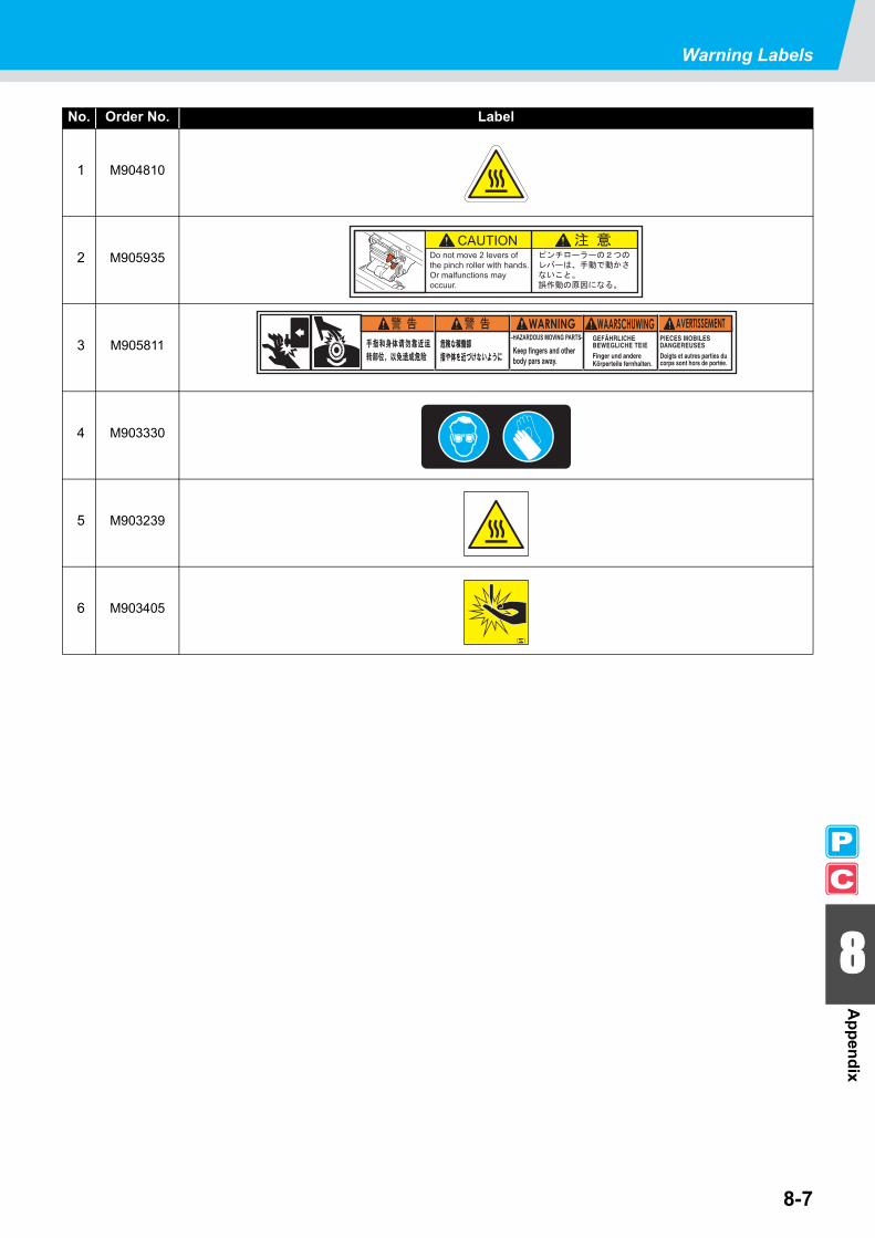
Warning Labels
8-7
8
Appendix
No. Order No. Label
1 M904810
2 M905935
3 M905811
4 M903330
5 M903239
6 M903405

8-8
Inquiry SheetUse this sheet for troubles and abnormal functioning of the machine. Fill in the following necessary items and fax the sheet to our service office.
Company name
Person in charge
Phone number
Machine model
Used OS
Machine information*1
*1. See "Confirming Machine Information" ( P.5-14) of "Chapter 5 Extended Functions - Common Settings -" and fill in the sheet.
Error message
Inquiry details

8-9
8
Appendix
Function FlowchartPrint mode Cut mode
Display
Mainte(P.8-22)
Machine(P.8-28)
Setup(P.8-16)
Common (P.8-36)
Common setup
ENGLISH / DEUTSCH / FRANCAIS / ESPANOL / ITALIANO / PORTUGESE
Mainte(P.8-34)
Copies(P.8-34)
FUNCT I ONSETUP < ENT >
< LOCA L . 1 > [ # 0 1 ]WI DTH : * * * * mm
FUNCT I ONMA I NTENANCE < ENT >
FUNCT I ONMACH I NE SETUP < ENT >
< LOCA L . C > [ # 0 1 ][ CUT 1 ] 3 0 6 0 0 . 3 0
FUNCT I ON CMA I NTENANCE < ENT >
FUNCT I ON CNo . COP I ES < ENT >
Setup(P.8-30)
FUNCT I ON CSETUP < ENT >
FUNCT I ONCOMMON SETUP < ENT >
FUNCT I OND I SP L AY < ENT >
D I SP L AYJ APANESE

8-10
LOCAL Menu on the Printer Mode
C L E AN I NGT Y P E : NORMA L
C L E AN I NG AC T I V E0 0 : 0 0
C L E AN I NGT Y P E : SOF T
< L OCA L . 1 > [ # 0 1 ]WI D T H : * * * * mm
OR I G I N S E T UP0 . 0 - - - -
OR I G I N S E T UP* * OR I G I N * *
MED I A CU T< e n t >
End including origin setup
PRE PR T POS T3 5 ° C 4 0 ° C 5 0 ° C
4 0 ° C 4 0 ° C 5 0 ° C( OF F OF F OF F )
T E S T PR I N T( SCAN D I R . ) < EN T >
* * T E S T PR I N T * *
DA T A C L E AR< EN T >
* * DA T A C L E AR * *
US ER T Y P E CHANGET Y P E ( 1 ) - > < 2 > : e n t
SCAN DIR. / FEED DIR. /WHITE CHK.
To P8-12
C L E AN I NGT Y P E : HARD
C L E AN I NGT Y P E : S POT Select a color to maintain.

8-11
Function Flowchart
8
Appendix
Shake the cartridge fifth or sixth times.
MED I A RE S I DUA L PR I N T< EN T >
Only when [MEDIA RESIDUAL] is “ON”
Remove the cartridge. Set the cartridge.

8-12
From P8-10
B S * I NK MMCCY Y K KREMA I N 3 4 5 6 7 8 9 9
HE AD HE I GH T : T h i n[ MMMMMMM ] : 1 0 0 0mm

8-13
Function Flowchart
8
Appendix
C J V 3 0 - 6 0 B S V 1 . 0 0MR L - I I I V 1 . 0 0
WRONG I NK I CM - C - - - - K
NON - OR I G I NA L I NKM - C - - - - K
k i n d o f I NKM - C - - - - K
WRONG CAR T R I DGEM - C - - - - K
C o l o r o f I NKM - C - - - - K
NO CAR T R I DGEM - C - - - - K
I NK REMA I N Z EROM - C - - - - K
E x p i r a t i o n : 2MON T HM - C - - - - K
I NK ENDM - C - - - - K
E x p i r a t i o n : 1MON T HM - C - - - - K
I NK NE AR ENDM - C - - - - K
E x p i r a t i o nM - C - - - - K

8-14
LOCAL Menu on the Cut Mode
OR I G I N S E T UP0 . 0 - - - -
OR I G I N S E T UP* * OR I G I N * *
< L OCA L . C > [ # 0 1 ]CU T 1 ( 3 0 / 6 0 / 0 . 3 0 )
MED I A CUT< e n t >
End including origin setup
CU T HE AD RE T RAC T< EN T >
P L E A S E WA I T
T E S T CU T< EN T >
* * T E S T CUT * *
MED I A F E ED: 0 . 1m
* * MED I A F E ED * *
DA T A C L E AR< EN T >
* * DA T A C L E AR * *
S PD PRS OF S[ CU T 1 ] 3 0 6 0 0 . 3 0
0.1 ~ 500.0 m
S E T UP DRAWI NG ARE A0 . 0 - - - -
( 1 0 0% = 0 . 5 G )[ CU T 1 ] ACC . L v . = 1 0 0%
HE A T ER P o w e r - o f f< EN T >

8-15
Function Flowchart
8
Appendix

8-16
To P8-18To P8-18
Setup (Printer Mode)
S E T UPS E L EC T : T Y P E . 1
[ 1 ]P I NCH RO L L ER < e n t >
ENDS : H I GH [ H _ _ _ _ _ H ]I NNER : OF F N o . 6 t o 1
[ 1 ] HE A T ERS E T T I ME < e n t >
TYPE. 2TYPE. 3TYPE. 4
[ 1 ]MED I A COMP . < e n t >
[ 1 ] MED I A COMP .PR I N T S T AR T : e n t
[ 1 ]DROP . POS c o r r e c t < e n t >
[ 1 ] DROP . POS c o r r e c ( L )PR I N T S T AR T : e n t
[ 1 ]HE A T ER < e n t >
[ 1 ] HE A T ERS E T T EMP . < e n t >
[ 1 ]PR I N T MODE < e n t >
[ 1 ] PR I N T MODEDRA F T QUA L I T Y < e n t >
[ 1 ] PR I N T MODEF I NE QUA L I T Y < e n t >
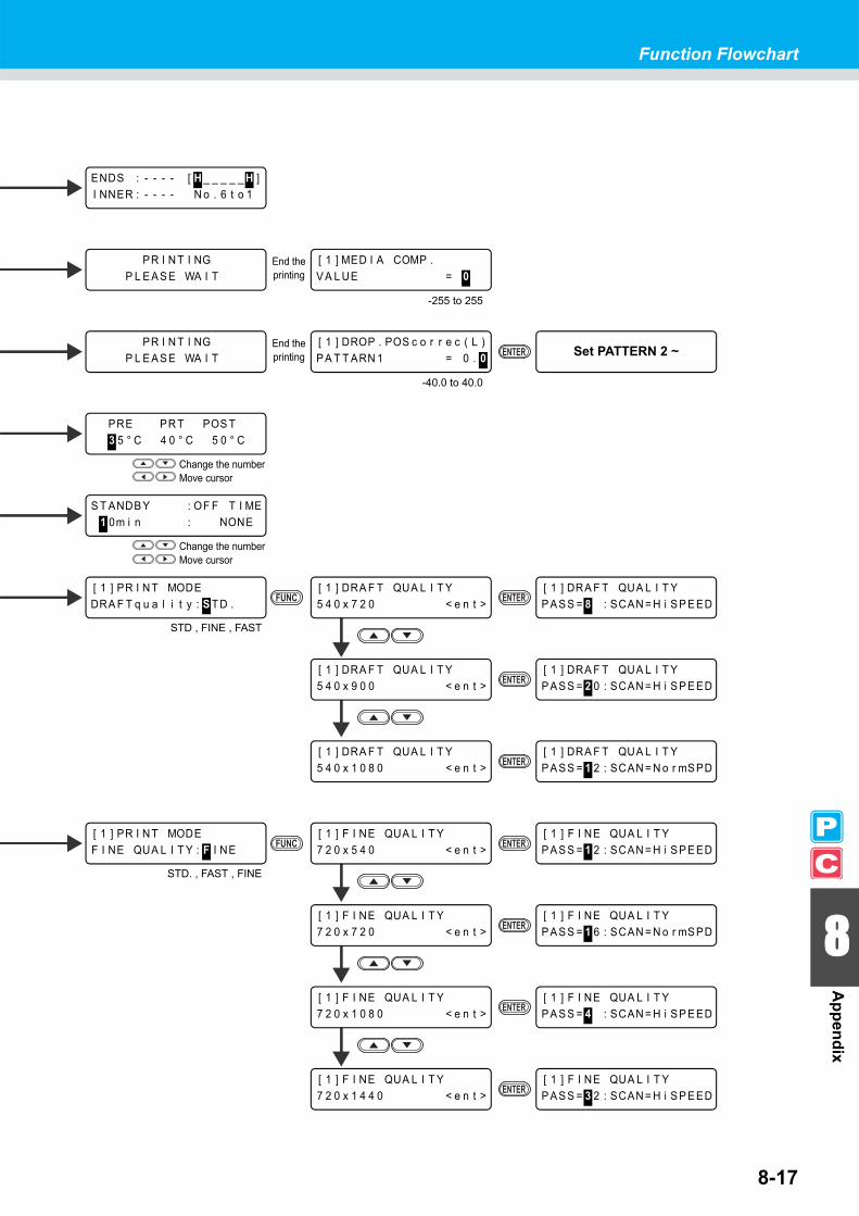
8-17
Function Flowchart
8
Appendix
ENDS : - - - - [ H _ _ _ _ _ H ]I NNER : - - - - N o . 6 t o 1
PRE PR T POS T3 5 ° C 4 0 ° C 5 0 ° C
Change the number Move cursor
S T ANDB Y : OF F T I ME1 0m i n : NONE
[ 1 ] MED I A COMP .V A L UE = 0
PR I N T I NGP L E A S E WA I T
-255 to 255
End the printing
[ 1 ] DROP . POS c o r r e c ( L )P A T T ARN 1 = 0 . 0
PR I N T I NGP L E A S E WA I T
-40.0 to 40.0
End the printing Set PATTERN 2 ~
[ 1 ] DRA F T QUA L I T Y5 4 0 x 7 2 0 < e n t >
[ 1 ] PR I N T MODEDRA F T q u a l i t y : S T D .
STD , FINE , FAST
[ 1 ] DRA F T QUA L I T YP A S S = 8 : SCAN = H i S P E ED
[ 1 ] DRA F T QUA L I T Y5 4 0 x 1 0 8 0 < e n t >
[ 1 ] DRA F T QUA L I T YP A S S = 1 2 : SCAN = N o r mS PD
[ 1 ] F I NE QUA L I T Y7 2 0 x 5 4 0 < e n t >
[ 1 ] PR I N T MODEF I NE QUA L I T Y : F I NE
STD. , FAST , FINE
[ 1 ] F I NE QUA L I T YP A S S = 1 2 : SCAN = H i S P E ED
[ 1 ] F I NE QUA L I T Y7 2 0 x 7 2 0 < e n t >
[ 1 ] F I NE QUA L I T YP A S S = 1 6 : SCAN = N o r mS PD
[ 1 ] F I NE QUA L I T Y7 2 0 x 1 0 8 0 < e n t >
[ 1 ] F I NE QUA L I T YP A S S = 4 : SCAN = H i S P E ED
[ 1 ] F I NE QUA L I T Y7 2 0 x 1 4 4 0 < e n t >
[ 1 ] F I NE QUA L I T YP A S S = 3 2 : SCAN = H i S P E ED
[ 1 ] DRA F T QUA L I T Y5 4 0 x 9 0 0 < e n t >
[ 1 ] DRA F T QUA L I T YP A S S = 2 0 : SCAN = H i S P E ED
Change the number Move cursor

8-18
[ 1 ]AU TO CU T < e n t >
[ 1 ] AU TO CU TS E T UP : OF F
[ 1 ]PRE - F E ED < e n t >
[ 1 ] PRE - F E EDS E T UP : OF F
[ 1 ]CO L OR P A T T ERN < e n t >
[ 1 ] COL OR P A T T ERNS E T UP : ON
ON / OFF
ON / OFF
ON / OFF
[ 1 ]RE F RE SH < e n t >
[ 1 ] RE F RE SHS E T UP : L E V E L 3
LEVEL 0 to 3
[ 1 ] V ACUUMS E T UP : S T ANDARD
[ 1 ] F e e d S P E ED L E V E LL E V E L : 1 0 0%
10 to 200 %
[ 1 ]V ACUUM < e n t >
[ 1 ]F e e d S P E ED L E V E L < e n t >
OFF / STANDARD / WEAK /LittleWEAK / STRONG
To P8-20
From P8-16 From P8-16
[ 1 ] PR I N T MODESCAN D I REC T I ON < e n t >
[ 1 ] PR I N T MODEL OG I CA L S E E K < e n t >
[ 1 ] I NK L A Y ERSS E T UP : 1
[ 1 ]DRY I NG T I ME < e n t >
SCAN : PR I N T END0 . 0 s : 0 s
[ 1 ]I NK L A Y ERS < e n t >
1 to 9
Change the number Move cursor

8-19
Function Flowchart
8
Appendix
[ 1 ] PR I N T MODES c a n D I REC T I ON : B i - D
Bi-D , Uni-D
[ 1 ] PR I N T MODEL OG I CA L S E E K : ON
ON / OFF

8-20
[ 1 ] S E T UP RE S E TRE S E T : e n t
[ 1 ]S E T UP RE S E T < e n t >
[ 1 ]AU TO C L E AN I NG < e n t >
[ 1 ] AU TO C L E AN I NGS E T UP : ON
[ 1 ]P r i n t . C L E AN I NG< e n t >
[ 1 ] P r i n t . C L E AN I NGS E T UP : ON
ON / OFF
ON / OFF
Select ON
[ 1 ] S E T UP COP YT Y P E . 1 - > T Y P E . 2
[ 1 ]S E T UP COP Y < e n t >
TYPE.1 to 4 , ALL
From P8-18
[ 1 ] PR I OR I T YS E T UP : I ND I V I DUA L L Y
[ 1 ]PR I OR I T Y < e n t >
INDIVIDUALLY , ALL HOSTALL PANEL
When INDIVIDUALLY is selected
Select ON

8-21
Function Flowchart
8
Appendix
[ 1 ] PR I OR I T YDRY I NG T I ME : HOS T
[ 1 ] PR I OR I T YI NK L A Y ERS : HOS T
HOST / PANEL HOST / PANEL
[ 1 ] PR I OR I T YAU TO CUT : HOS T
HOST / PANEL
[ 1 ] PR I OR I T YHE A T ER : HOS T
[ 1 ] PR I OR I T YMED I A COMP . : HOS T
HOST / PANEL HOST / PANEL
[ 1 ] PR I OR I T YPR I N T MODE : HOS T
HOST / PANEL
[ 1 ] PR I OR I T YCOL OR P A T T ERN : HOS T
[ 1 ] PR I OR I T YPRE - F E ED : HOS T
HOST / PANEL HOST / PANEL
[ 1 ] PR I OR I T YRE F RE SH : HOS T
HOST / PANEL
[ 1 ] PR I OR I T YF E ED S PD . L E V E L : HOS T
[ 1 ] PR I OR I T YV ACUUM : HOS T
HOST / PANEL HOST / PANEL
I N T ERV A L : T Y P E1 0 0 0mm : NORMA L
I N T ERV A L : T Y P E1 0 0 0mm : NORMA L
Initialize the setup parameter of selected user type
COP Y : e n tT Y P E . 1 - > T Y P E . 2
Start copy
Change the number Move cursor
Change the number Move cursor
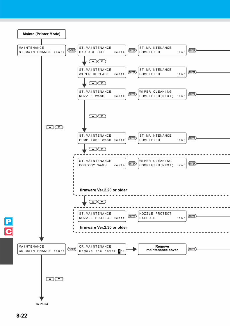
8-22
CR . MA I N T ENANCER emo v e t h e c o v e r : e n t
Remove maintenance cover
S T . MA I N T ENANCECOS TODY WA SH < e n t >
WI P ER C L E AN I NGCOMP L E T ED ( NE X T ) : e n t
Mainte (Printer Mode)
MA I NT ENANCES T . MA I N T ENANCE < e n t >
S T . MA I N T ENANCECAR I AGE OU T < e n t >
S T . MA I N T ENANCECOMP L E T ED : e n t
S T . MA I N T ENANCEWI P ER RE P L ACE < e n t >
S T . MA I N T ENANCECOMP L E T ED : e n t
S T . MA I N T ENANCEPUMP T UB E WA SH < e n t >
S T . MA I N T ENANCECOMP L E T ED : e n t
S T . MA I N T ENANCENOZ Z L E WA SH < e n t >
WI P ER C L E AN I NGCOMP L E T ED ( NE X T ) : e n t
MA I NT ENANCECR . MA I N T ENANCE < e n t >
To P8-24
firmware Ver.2.20 or older
S T . MA I N T ENANCENOZ Z L E PROT EC T < e n t >
NOZ Z L E PROT ECTE X ECU T E : e n t
firmware Ver.2.30 or older

8-23
Function Flowchart
8
Appendix
S T . MA I N T ENANCECOMP L E T ED : e n t
Leave for the set time
To Local after initializing
S T . MA I N T ENANCEL E A V I NG T I ME : 1m i n
F i l l t h e l i q u i d .COMP L E T ED ( NE X T ) : e n t
S T . MA I N T ENANCEL E A V I NG T I ME : 1m i n
F i l l t h e l i q u i dCOMP L E T ED ( NE X T ) : e n t
1 to 99 min
1 to 99 min
CR . MA I N T ENANCECOMP L E T ED : e n t
CR . MA I N T ENANCECAR I AGE OU T : e n t
To Local after initializing
To Local after initializing
To Local after initializing
Leave for the set time
To Local after initializing
To Local after initializing
To Local after initializing
NOZ Z L E PROT EC TP L E A S E WA I T
NOZ Z L E PROT EC T0 0 : 0 0

8-24
S L E E P S E T UPPUMP T UB E WA SH < e n t >
S L E E P S E T UPWA SH I N T ERV A L = 4 h
S L E E P S E T UPC L E AN I NG < e n t >
S L E E P S E T UPC L E AN . I NT ERV A L = 4 h
MA I NT ENANCES L E E P S E T UP < e n t >
S L E E P S E T UPRE F RE SH < e n t >
S L E E P S E T UPRE F RE SH i n t e r v a l = 4 h
HD . MA I N T ENANCEMa i n t Wa s h L i q u i d < e n t >
Ma i n t Wa s h L i q u i dF I L L I NG UP < e n t >
MA I NT ENANCEHD . MA I N T ENANCE < e n t >
HD . MA I N T ENANCEF I L L UP I NK < e n t >
F I L L I NG UP0 0 : 0 0
HD . MA I N T ENANCED I SCHARGE &WA SH < e n t >
R emo v e : I n k C a r t r i d g e sMMCCY Y K K
To P8-26
From P8-22
Ma i n t Wa s h L i q u i dD I SCHARGE < e n t >
OFF/1 to 168h
OFF/1 to 168h
OFF/1 to 168h

8-25
Function Flowchart
8
Appendix
S e t : Wa s h i n g C a r t r i d g e1 2 3 4 5 6 7 8
* A B SORP T I ON *0 0 : 0 0
* D I SCHARGE *0 0 : 0 0
Ma i n t Wa s h L i q u i dF I L L I NG UP S T AR T : e n t
Ma i n t Wa s h L i q u i dD I SCHARGE S T AR T : e n t
R emo v e : C a r t r i d g e s1 2 3 4 5 6 7 8
* D I SCHARGE *0 0 : 0 0
* A B SORP T I ON *0 0 : 0 0
S E L EC T :END < > R e - Wa s h
Ma i n t Wa s h L i q u i dCAR T R I DGE : n o n e
R emo v e : Ma i n t . Wa s h
S L E E P S E T UPC L E AN . T Y P E : NORMA L
NORMAL / SOFT / HARD
Settable except for OFF
* D I SCHARGE *0 0 : 0 0
S e t : Wa s h i n g C a r t r i d g e1 2 3 4 5 6 7 8
R emo v e : C a r t r i d g e s1 2 3 4 5 6 7 8
Set a cartridge
Remove maintenance washing

8-26
A u t o N Z L . PROT EC TON T i me = 1 6 h
MA I N T ENANCEA u t o N Z L . PROT EC T < e n t >
A u t o N Z L . PROT EC TON T i me < e n t >
A u t o N Z L . PROT EC TI n t e r v a l < e n t >
A u t o N Z L . PROT EC T i n t r lN umb e r o f d a t s = 7 d
OFF/1 to 14day
OFF/1 to 24h
firmware Ver.2.30 or older
ROU T I NE W I P I NGSCAN COUN T < e n t >
ROU T I NE S E T UPRE F RE SH < e n t >
ROU T I NE S E T UPRE F RE SH i n t e r v a l = 4 h
MA I NT ENANCEROU T I NE S E T UP < e n t >
ROU T I NE S E T UPROU T I NE WI P I NG < e n t >
From P8-24
ROU T I NE W I P I NGT EMP . d i f f e r e n c e < e n t >
OFF/1 to 168h
ROU T I NE S E T UPPUMP T UB E WA SH < e n t >
ROU T I NE S E T UPWA SH I N T ERV A L = 4 h
ROU T I NE S E T UPC L E AN I NG < e n t >
ROU T I NE S E T UPC L E AN . I NT ERV A L = 4 h
OFF/1 to 168h
OFF/1 to 168h
MA I NT ENANCEWI P ER L E V E L < e n t >
WI P ER L E V E LL E V E L : 1 0 / 1 0
1/10 to 10/10
MA I NT ENANCEI n k T a n k R e p l a c e < e n t >
I n k T a n k R e p l a c eRE P L ACE : e n t
MED I A RE S I DUA LS E T UP : OF F
MA I NT ENANCEMED I A RE S I DUA L < e n t >
ON / OFF
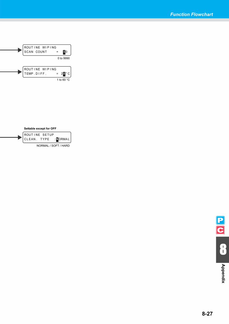
8-27
Function Flowchart
8
Appendix
ROUT I NE S E T UPC L E AN . T Y P E : NORMA L
NORMAL / SOFT / HARD
ROUT I NE WI P I NGSCAN COUN T = 5 0
ROUT I NE WI P I NGT EMP . D I F F . = 2 0 ° C
Settable except for OFF
1 to 60 °C
0 to 9990

8-28
MACH I NE S E T UP6 0 0 c c C a r t r i d g e < e n t >
CAR T . S l o t . . 3 . . . . .1 . 3 4 . . 7 .
MACH I NE S E T UPS T AMP S E T UP < e n t >
MACH I NE S E T UPT e s t PR T . A r r a n g e < e n t >
T e s t P r i n t A r r a n g eS E T UP : F E ED D I R .
FEED DIR./ SCAN DIR.
Machine (Printer Mode)
MACH I NE S E T UPDEODOR I Z E F AN < e n t >
DEODOR I Z E F ANS TOP T I ME < e n t >
DEODOR I Z E F ANS TOP T I ME = 1 2 0M i n
DEODOR I Z E F ANRENEW < e n t >
DEODOR I Z E F ANRENEW : ON
MACH I NE S E T UPDRYNE S S F E ED < e n t >
DRYNE S S F E EDS E T UP : ON
S T AMP S E T UPS T AMP : OF F
MACH I NE S E T UPWa s t e I n k Wa r n i n g < e n t >
Wa s t e I n k Wa r n i n gS E T UP : ON
ON / OFF
ON / OFF
ON / OFF
ON / OFF
0 to 240 min /CONTINUE
CAR T . S l o t . . 3 . . . . .c a s e w e i g h t = 3 0 0 g
300 to 500 g
MACH I NE S E T UPCAR T . PR I OR I T Y < e n t >
CAR T . PR I OR I T YS E L EC T : I NK L E V E L
INK LEVEL / EXP.DATE
This function is available for the firmware Ver.2.30 and later.
MACH I NE S E T UPENV . T EMP . < e n t >
MACH I NE S E T UPS E L : Wa i t a r r i v a l
Wait arrival / Not wait ARR.

8-29
Function Flowchart
8
Appendix

8-30
To P8-32
Setup (Cut Mode)
S E T UPS E L EC T : CUT 1
[ CU T 1 ]P I NCH ROL L ER < e n t >
ENDS : H I GH [ H _ _ _ _ _ H ]I NNER : OF F N o . 6 t o 1
CUT2CUT3
PENHALF [ CU T 1 ]
MARK DE T EC T < e n t >[ CU T 1 ] MARK DE T EC TDE T EC T : OF F
[ CU T 1 ]CU T MODE < e n t >
[ CU T 1 ] CUT MODES E T UP : S T D .
[ CU T 1 ]AU TO CU T < e n t >
[ CU T 1 ] AUTO CUTS E T UP : OF F
OFF, 1pt, 2pt X,2pt Y, 3pt, 4pt
STD. / FINE / FAST
OFF / ON
[ CU T 1 ]P / C AD J US T < e n t >
[ CU T 1 ] P / C AD J US TP / C OR I G I N OF S . < e n t >
[ CU T 1 ] P / C AD J US TP / C SCA L E AD J . < e n t >

8-31
Function Flowchart
8
Appendix
[ CUT 1 ] AU TO CU TCU T MARG I N = 3 0mm
ENDS : - - - - [ H _ _ _ _ _ H ]I NNER : - - - - N o . 6 t o 1
[ CUT 1 ] MARK DE T EC TS P E ED L I M I T = 1 c m / s
[ CU T 1 ] MARK DE T EC TOF F S E T Y ( ) = 0 . 0mm
[ CUT 1 ] MARK DE T EC TS I Z E = 1 0mm
-40.0 to 40.0 mm
[ CU T 1 ] MARK DE T EC TCOP I E S Y ( ) = 1
[ CUT 1 ] MARK DE T EC TFORM : T Y P E 1
1 to 9999
[ CU T 1 ] MARK DE T EC TOF F S E T X ( ) = 0 . 0mm
[ CU T 1 ] MARK DE T EC TCOP I E S X ( ) = 1
4 to 40 mm
TYPE 1 / TYPE 2
-40.0 to 40.0 mm
1 to 9999
1 to 30 cm/s
0 to 30 mm
Only when AUTO CUT is ON
[ CU T 1 ] MARK DE T EC TS K EW CHECK = 0mm
0 to 99 mm
P / C OR I G I N OF S .PR I N T S T AR T : e n t
P / C OR I G I N OF S .5 4 0 d p i < e n t >
P / C OR I G I N OF S .Y = 0 X = 0
P / C SCA L E AD J .AD J . V A L UE = 5
P / C SCA L E AD J .C L E AR < > PR I N T
P / C SCA L E AD J .D I REC T I ON = +
540dpi/720dpi
Adjust misalignment
Print all the pattern.Cut the pattern 0.
Check misalignment of the pattern 0
+ / -
Remove the printed & cut pattern
Cut the pattern 1 to 9 Enter the fit pattern

8-32
[ CU T 1 ]T A K EUP T I MM I NG < e n t >
[ CU T 1 ] T A K EUP T I MM I NGS E T UP : OF F
OFF / 1 to 99
[ CU T 1 ]AD J - PRS OF F S E T < e n t >
[ CU T 1 ] AD J - PRS OF F S E TOF F S E T = 3
[ CU T 1 ]SOR T I NG < e n t >
[ CU T 1 ] SOR T I NGS E T UP : OF F
OFF / ON
1 to 7
[ CU T 1 ]V ACUUM < e n t >
[ CU T 1 ] V ACUUMS E T UP : S T RONG
OFF / STRONG / WEAK /LittleWEAK / STANDARD
From P8-30
[ CU T 1 ]S E T UP RE S E T < e n t >
[ CU T 1 ] S E T UP RE S E TRE S E T : e n t
[ CU T 1 ]OV ER CU T < e n t >
[ CU T 1 ] OV ER CUTL ENGT H 0 . 1mm
OFF / 0.1 to 1.0 mm
[ CU T 1 ] S E T UP COP YCU T 1 - > CU T 2
[ CU T 1 ]S E T UP COP Y < e n t >
CUT1 to 3 / PEN / HALF / ALL
[ CU T 1 ]D I V I S I ON CUT < e n t >
[ CU T 1 ] D I V I S I ON CU TS E T UP : OF F
[ HA L F ]HA L F CU T < e n t >
[ HA L F ] HA L F CUTHA L F CU T PRE S . = 0 g
OFF / ON
0 to 300 g
Only when tool condi-tion [HALF] is selected
[ CU T 1 ]UP S P E ED < e n t >
[ CU T 1 ] UP S P E EDS E T UP : AU TO
AUTO , 5 , 10 , 20 , 30 cm/s
[ CU T 1 ]DUMMY CU T < e n t >
[ CU T 1 ] DUMMY CU TS E T UP : OF F
[ CU T 1 ]MED I A T Y P E < e n t >
[ CU T 1 ] MED I A T Y P ES E T UP : S T ANDARD
OFF / ON
STANDARD / HEAVY
Not displayed when tool condition [PEN] is selected

8-33
Function Flowchart
8
Appendix
[ CU T 1 ] SOR T I NGARE A : OF F
[ CUT 1 ] SOR T I NGAU TO F E ED : OF F
OFF / ON OFF / 10 to 5100 cm
COP Y : e n tCU T 1 - > CU T 2
Start copy
[ CU T 1 ] D I V I S I ON CU TMARK CU T : OF F
[ CUT 1 ] D I V I S I ON CUTF RAME CU T : ON
[ HA L F ] HA L F CU TCU T L ENGT H = 1 0mm
[ HA L F ] HA L F CU THA L F L ENGT H = 0 . 5mm
OFF / ON OFF / ON
0.1 to 6.0 mm 5 to 150 mm
Only when DIVISION CUT is ON

8-34
Draw pattern
MED I A CU TI N T ERV A L = 5 0 0mm
MED I A CUTF RON T CUT OF F = 3 0mm
Mainte (Cut Mode)
MA I NT ENANCEMARK S ENSOR < e n t >
MARK S ENSORS ENSOR CHECK < e n t >
S ENSOR CHECKOR I G I N S E T : e n t
MARK S ENSORPO I N T ER OF F S E T < e n t >
S AMP L E CU TS E L EC T : LOGO
S AMP L E CU TL OGO : 1 0 0%
MARK S ENSORL E V E L AD J US T < e n t >
L E V E L AD J US TOU T : 0 0 0 0 I N : 0 0 0 0
MA I NT ENANCES AMP L E CU T < e n t >
MA I NT ENANCEMED I A CU T < e n t >
MA I NT ENANCETOO L RE P L ACE < e n t >
TOOL RE P L ACEAC T I ON : e n t
TOO L RE P L ACECOMP L E T ED : e n t
0 to 500 mm
1 to 999 %
10 to 10000 mm
LOGO / CUT
Only when LOGO is selected
S T E P S I Z ES I Z E = 0 . 0 2 5
MA I NT ENANCES T E P S I Z E < e n t >
0.025 / 0.01
Operation starts after changing to REMOTE
Copies (Cut Mode)
N o . COP I E SCOP I E S = 1
N o . COP I E SI N T ERV A L = 2mm
0 to 30 mm1 to 999

8-35
Function Flowchart
8
Appendix
Changes to REMOTE after cutting pattern
S ENSOR CHECKFORM : T Y P E 1
S ENSOR CHECKS I Z E = 1 0mm
S ENSOR CHECKS P E ED = 1 0 c m / s
S AMP L E CU TCU T S T AR T : e n t
MED I A CU TCOUN T = 1
PO I N T ER OF F S E TY = 0 . 0 X = 0 . 0
Start operation
4 to 40 mm TYPE 1 / TYPE 2 5 to 10 cm/s
1 to 9999
To Local after initializing
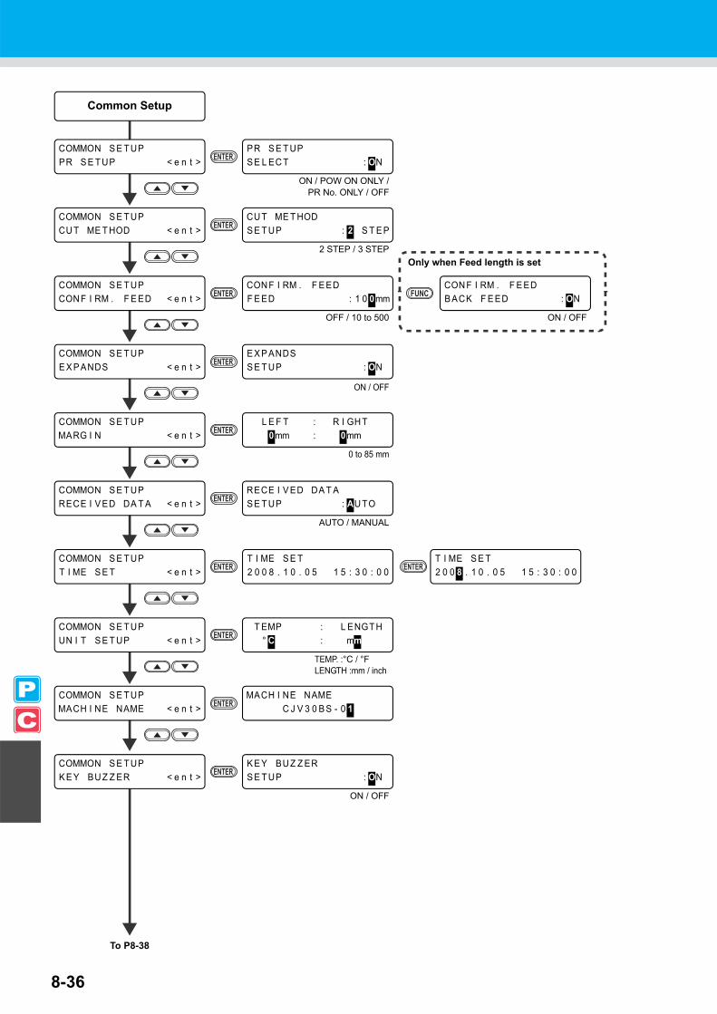
8-36
Common Setup
To P8-38
COMMON S E T UPT I ME S E T < e n t >
COMMON S E T UPCON F I RM . F E ED < e n t >
CON F I RM . F E EDF E ED : 1 0 0mm
T I ME S E T2 0 0 8 . 1 0 . 0 5 1 5 : 3 0 : 0 0
T I ME S E T2 0 0 8 . 1 0 . 0 5 1 5 : 3 0 : 0 0
COMMON S E T UPUN I T S E T UP < e n t >
T EMP : L ENGT H° C : mm
COMMON S E T UPMACH I NE NAME < e n t >
MACH I NE NAMEC J V 3 0 B S - 0 1
OFF / 10 to 500
TEMP. :°C / °FLENGTH :mm / inch
CON F I RM . F E EDB ACK F E ED : ON
ON / OFF
Only when Feed length is set
COMMON S E T UPPR S E T UP < e n t >
PR S E T UPS E L EC T : ON
COMMON S E T UPMARG I N < e n t >
L E F T : R I GH T0mm : 0mm
COMMON S E T UPRECE I V ED DA T A < e n t >
RECE I V ED DA T AS E T UP : AU TO
ON / POW ON ONLY /PR No. ONLY / OFF
0 to 85 mm
AUTO / MANUAL
COMMON S E T UPCU T ME T HOD < e n t >
CU T ME T HODS E T UP : 2 S T E P
2 STEP / 3 STEP
COMMON S E T UPE X P ANDS < e n t >
E X P ANDSS E T UP : ON
ON / OFF
COMMON S E T UPK E Y BU Z Z ER < e n t >
K E Y BUZ Z ERS E T UP : ON
ON / OFF

8-37
Function Flowchart
8
Appendix

8-38
I N FORMA T I ONS ER I A L N o < e n t >
S ER I A L N o0 0 0 0 0 0 0 0
I N FORMA T I ONMA I N T E . H I S TORY < e n t >
I N FORMA T I ONERROR H I S TORY < e n t >
ERROR H I S TORY[ 0 1 ] 0 7 . 1 0 . 1 0 1 2 : 1 5
[ 0 1 ] 0 5 . 0 9 . 2 9 0 8 : 1 8CARR I AGE OU T
I N FORMA T I ONPR I N Tmo d e H I S T . < e n t >
[ 0 1 ] 7 2 0 x 1 0 8 0 . 1 2B d . V d . x 1 . 1 L : 1 2 . 3 4m
I N FORMA T I ONL I S T < e n t >
L I S TS E L EC T : PR I N T MODE
I N FORMA T I ONV ERS I ON < e n t >
C J V 3 0 - 6 0 B S V 1 . 0 0MR L - I I I V 1 . 0 0
From P8-36
COMMON S E T UPI N FORMA T I ON < e n t >
PRINT MODE / CUT MODE /REPLACE COUNTER / ALL
Select with
Select with
Select with

Function Flowchart
8-39
8
Appendix
PR I N Tmo d e H I S T .[ 0 1 ] 0 5 . 0 9 . 2 9 0 9 : 5 7
Displays error
L I S T* * PR I N T I NG * *
Select with
Select with

8-40

D201979-13-19012011

NHFW : 2.3© MIMAKI ENGINEERING CO., LTD.2011