Embed Size (px)
Citation preview
Hani Kamhawi, John T. Yim, Michael J. Patterson, and Penni J. DaltonGlenn Research Center, Cleveland, Ohio
Operational Status of the International Space Station Plasma Contactor Hollow Cathode Assemblies FromJuly 2011 to May 2013
NASA/TM—2014-216579
April 2014
AIAA–2013–4114
https://ntrs.nasa.gov/search.jsp?R=20140007510 2018-05-12T09:19:27+00:00Z
NASA STI Program . . . in Profi le
Since its founding, NASA has been dedicated to the advancement of aeronautics and space science. The NASA Scientifi c and Technical Information (STI) program plays a key part in helping NASA maintain this important role.
The NASA STI Program operates under the auspices of the Agency Chief Information Offi cer. It collects, organizes, provides for archiving, and disseminates NASA’s STI. The NASA STI program provides access to the NASA Aeronautics and Space Database and its public interface, the NASA Technical Reports Server, thus providing one of the largest collections of aeronautical and space science STI in the world. Results are published in both non-NASA channels and by NASA in the NASA STI Report Series, which includes the following report types:
• TECHNICAL PUBLICATION. Reports of completed research or a major signifi cant phase of research that present the results of NASA programs and include extensive data or theoretical analysis. Includes compilations of signifi cant scientifi c and technical data and information deemed to be of continuing reference value. NASA counterpart of peer-reviewed formal professional papers but has less stringent limitations on manuscript length and extent of graphic presentations.
• TECHNICAL MEMORANDUM. Scientifi c and technical fi ndings that are preliminary or of specialized interest, e.g., quick release reports, working papers, and bibliographies that contain minimal annotation. Does not contain extensive analysis.
• CONTRACTOR REPORT. Scientifi c and technical fi ndings by NASA-sponsored contractors and grantees.
• CONFERENCE PUBLICATION. Collected papers from scientifi c and technical conferences, symposia, seminars, or other meetings sponsored or cosponsored by NASA.
• SPECIAL PUBLICATION. Scientifi c, technical, or historical information from NASA programs, projects, and missions, often concerned with subjects having substantial public interest.
• TECHNICAL TRANSLATION. English-language translations of foreign scientifi c and technical material pertinent to NASA’s mission.
Specialized services also include creating custom thesauri, building customized databases, organizing and publishing research results.
For more information about the NASA STI program, see the following:
• Access the NASA STI program home page at http://www.sti.nasa.gov
• E-mail your question to [email protected]
• Fax your question to the NASA STI Information Desk at 443–757–5803
• Phone the NASA STI Information Desk at 443–757–5802
• Write to: STI Information Desk
NASA Center for AeroSpace Information 7115 Standard Drive Hanover, MD 21076–1320
Hani Kamhawi, John T. Yim, Michael J. Patterson, and Penni J. DaltonGlenn Research Center, Cleveland, Ohio
Operational Status of the International Space Station Plasma Contactor Hollow Cathode Assemblies FromJuly 2011 to May 2013
NASA/TM—2014-216579
April 2014
AIAA–2013–4114
National Aeronautics andSpace Administration
Glenn Research CenterCleveland, Ohio 44135
Prepared for the49th Joint Propulsion Conference and Exhibitcosponsored by AIAA, ASME, SAE, and ASEESan Jose, California, July 14–17, 2013
Available from
NASA Center for Aerospace Information7115 Standard DriveHanover, MD 21076–1320
National Technical Information Service5301 Shawnee Road
Alexandria, VA 22312
Available electronically at http://www.sti.nasa.gov
Level of Review: This material has been technically reviewed by technical management.
NASA/TM—2014-216579 1
Operational Status of the International Space Station Plasma Contactor Hollow Cathode Assemblies From
July 2011 to May 2013
Hani Kamhawi, John T. Yim, Michael J. Patterson, and Penni J. Dalton National Aeronautics and Space Administration
Glenn Research Center Cleveland, Ohio 44135
Abstract The International Space Station has onboard two Aerojet Rocketdyne developed plasma contactor
units that perform the function of charge control. The plasma contactor units contain NASA Glenn Research Center developed hollow cathode assemblies. NASA Glenn Research Center monitors the on-orbit operation of the flight hollow cathode assemblies. As of May 31, 2013, HCA.001-F has been ignited and operated 123 times and has accumulated 8072 hours of operation, whereas, HCA.003-F has been ignited and operated 112 times and has accumulated 9664 hours of operation. Monitored hollow cathode ignition times and anode voltage magnitudes indicate that they continue to operate nominally.
Introduction The International Space Station (ISS) power system is designed with high voltage solar arrays
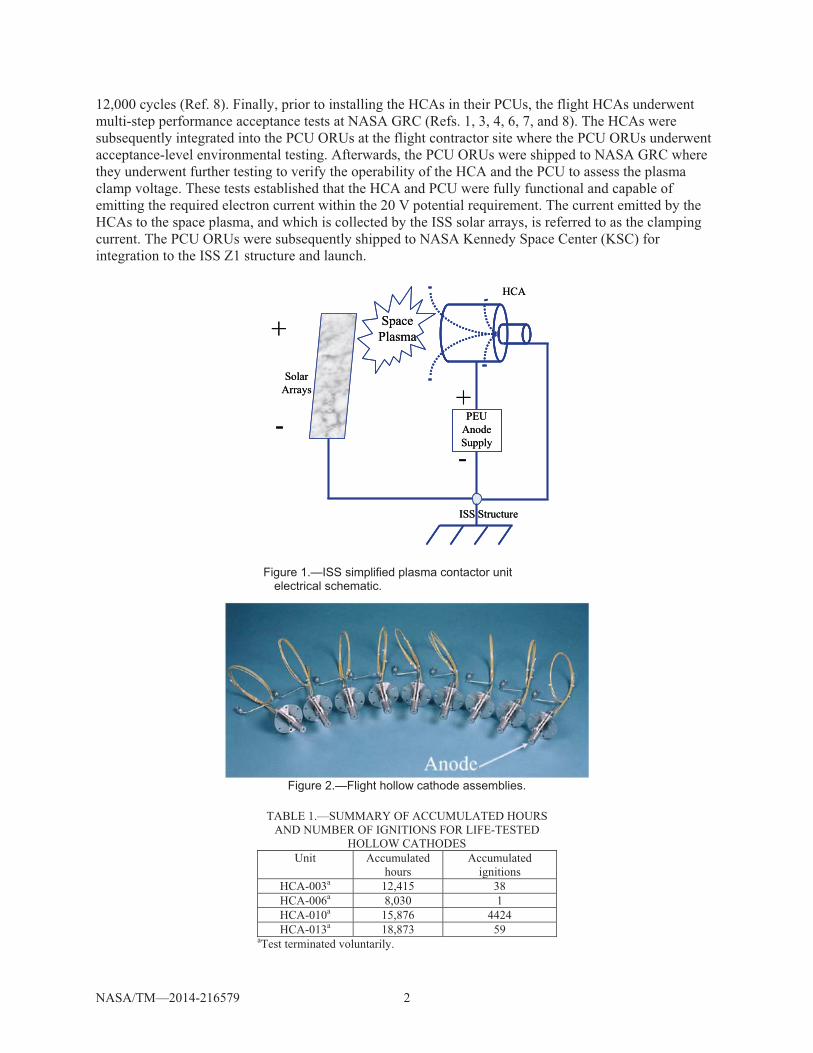
operating at output voltages of typically 140 to 160 V (Ref. 1). The power system is configured with a “negative ground” that electrically ties the habitat modules, structure, and radiators to the negative tap of the solar arrays. As a result of the electrical configuration and the plasma current balance, early analyses indicated that the habitat modules, structure, and radiators may float to voltages as high as 120 V with respect to the ambient space plasma (Ref. 1). Furthermore, given the large negative floating potentials, there exist the probability for deleterious interactions of the ISS and the space plasma. In 1992, a decision was made to baseline a plasma contactor on the ISS, from a variety of solutions, as a means to mitigate these interactions (Ref. 2). A plasma contactor establishes a low impedance plasma bridge to control the spacecraft potential relative to the local space plasma. Figure 1 illustrates the current path enabled through a plasma contactor. The plasma contactor unit (PCU) consists of a hollow cathode assembly (HCA), power electronics unit (PEU), and gas feed system (GFS). The entire unit is contained within an avionics box referenced as the orbit replaceable unit (ORU) (Ref. 1). The HCA within each PCU generates the electrons required for ISS charge control, and is electrically tied to the negative single point ground of the ISS main truss segment. The HCA consists of a low-work function insert for electron emission, a body tube with a heater, and an electrical isolator. During HCA operation, a continuous xenon flow of 6.0 to 7.5 sccm is maintained, a 3.0 A current to the anode is emitted, and the HCA emits to the space plasma for space charge control.
NASA Glenn Research Center (GRC) developed and delivered the flight HCAs, shown in Figure 2, for integration into the PCUs. The NASA GRC HCA development program included manufacture, test, and installation of engineering, qualification, and flight model HCAs according to the program requirements (Refs. 3 and 4). This included long duration testing of the devices to meet the 18,000 operational hours requirement. A 28,000+ hours operation test (Ref. 5) and a 19,000+ hours operation test (Ref. 6) were among the tests performed in support of this goal. Table 1 presents the final status of the life tested hollow cathode assemblies where all life tests were terminated voluntarily. In addition, a high fidelity development model HCA attained 32,000 successful ignition cycles, demonstrating the ISS requirement of 6,000 ignition cycles with at least 99 percent reliability (Ref. 7). HCA heater testing was also conducted to determine the cyclic life capability of the heater, which was found to be around
NASA/TM—2014-216579 2
12,000 cycles (Ref. 8). Finally, prior to installing the HCAs in their PCUs, the flight HCAs underwent multi-step performance acceptance tests at NASA GRC (Refs. 1, 3, 4, 6, 7, and 8). The HCAs were subsequently integrated into the PCU ORUs at the flight contractor site where the PCU ORUs underwent acceptance-level environmental testing. Afterwards, the PCU ORUs were shipped to NASA GRC where they underwent further testing to verify the operability of the HCA and the PCU to assess the plasma clamp voltage. These tests established that the HCA and PCU were fully functional and capable of emitting the required electron current within the 20 V potential requirement. The current emitted by the HCAs to the space plasma, and which is collected by the ISS solar arrays, is referred to as the clamping current. The PCU ORUs were subsequently shipped to NASA Kennedy Space Center (KSC) for integration to the ISS Z1 structure and launch.
Figure 2.—Flight hollow cathode assemblies.
TABLE 1.—SUMMARY OF ACCUMULATED HOURS
AND NUMBER OF IGNITIONS FOR LIFE-TESTED HOLLOW CATHODES
Unit Accumulated hours
Accumulated ignitions
HCA-003a 12,415 38 HCA-006a 8,030 1 HCA-010a 15,876 4424 HCA-013a 18,873 59
aTest terminated voluntarily.
+
- PEU Anode Supply
+
-
HCA
SolarArrays
ISS Structure
Space Plasma+
- PEU Anode Supply
+
-
HCA
SolarArrays
ISS Structure
Space Plasma
Figure 1.—ISS simplified plasma contactor unit electrical schematic.
NASA/TM—2014-216579 3
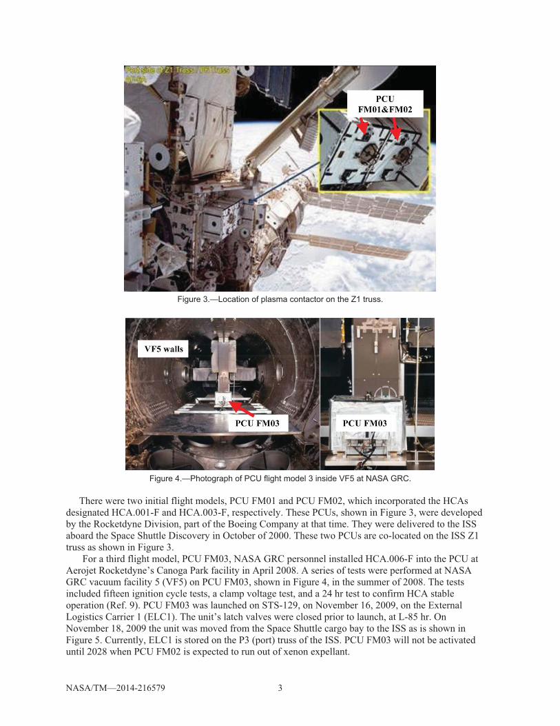
Figure 3.—Location of plasma contactor on the Z1 truss.
Figure 4.—Photograph of PCU flight model 3 inside VF5 at NASA GRC.
There were two initial flight models, PCU FM01 and PCU FM02, which incorporated the HCAs
designated HCA.001-F and HCA.003-F, respectively. These PCUs, shown in Figure 3, were developed by the Rocketdyne Division, part of the Boeing Company at that time. They were delivered to the ISS aboard the Space Shuttle Discovery in October of 2000. These two PCUs are co-located on the ISS Z1 truss as shown in Figure 3.
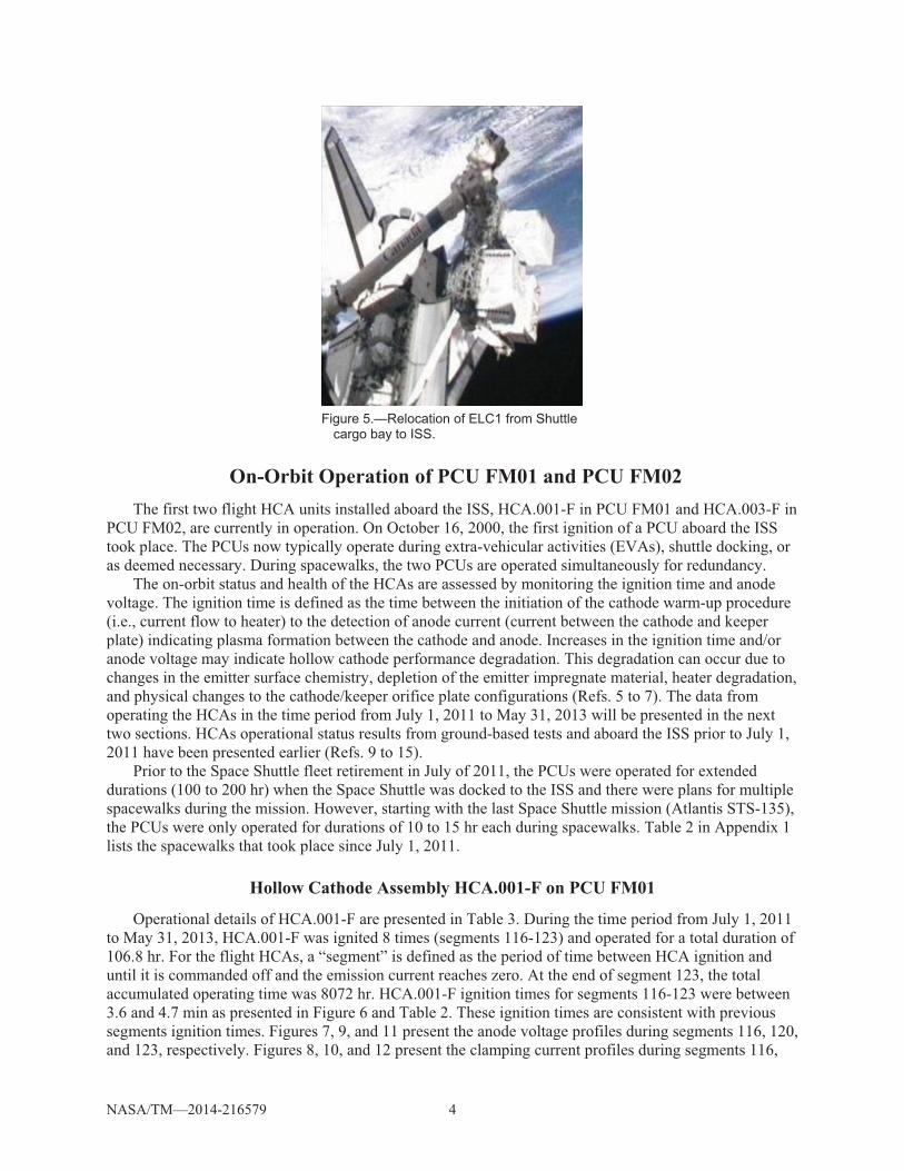
For a third flight model, PCU FM03, NASA GRC personnel installed HCA.006-F into the PCU at Aerojet Rocketdyne’s Canoga Park facility in April 2008. A series of tests were performed at NASA GRC vacuum facility 5 (VF5) on PCU FM03, shown in Figure 4, in the summer of 2008. The tests included fifteen ignition cycle tests, a clamp voltage test, and a 24 hr test to confirm HCA stable operation (Ref. 9). PCU FM03 was launched on STS-129, on November 16, 2009, on the External Logistics Carrier 1 (ELC1). The unit’s latch valves were closed prior to launch, at L-85 hr. On November 18, 2009 the unit was moved from the Space Shuttle cargo bay to the ISS as is shown in Figure 5. Currently, ELC1 is stored on the P3 (port) truss of the ISS. PCU FM03 will not be activated until 2028 when PCU FM02 is expected to run out of xenon expellant.
NASA/TM—2014-216579 4
Figure 5.—Relocation of ELC1 from Shuttle
cargo bay to ISS.
On-Orbit Operation of PCU FM01 and PCU FM02 The first two flight HCA units installed aboard the ISS, HCA.001-F in PCU FM01 and HCA.003-F in
PCU FM02, are currently in operation. On October 16, 2000, the first ignition of a PCU aboard the ISS took place. The PCUs now typically operate during extra-vehicular activities (EVAs), shuttle docking, or as deemed necessary. During spacewalks, the two PCUs are operated simultaneously for redundancy.
The on-orbit status and health of the HCAs are assessed by monitoring the ignition time and anode voltage. The ignition time is defined as the time between the initiation of the cathode warm-up procedure (i.e., current flow to heater) to the detection of anode current (current between the cathode and keeper plate) indicating plasma formation between the cathode and anode. Increases in the ignition time and/or anode voltage may indicate hollow cathode performance degradation. This degradation can occur due to changes in the emitter surface chemistry, depletion of the emitter impregnate material, heater degradation, and physical changes to the cathode/keeper orifice plate configurations (Refs. 5 to 7). The data from operating the HCAs in the time period from July 1, 2011 to May 31, 2013 will be presented in the next two sections. HCAs operational status results from ground-based tests and aboard the ISS prior to July 1, 2011 have been presented earlier (Refs. 9 to 15).
Prior to the Space Shuttle fleet retirement in July of 2011, the PCUs were operated for extended durations (100 to 200 hr) when the Space Shuttle was docked to the ISS and there were plans for multiple spacewalks during the mission. However, starting with the last Space Shuttle mission (Atlantis STS-135), the PCUs were only operated for durations of 10 to 15 hr each during spacewalks. Table 2 in Appendix 1 lists the spacewalks that took place since July 1, 2011.
Hollow Cathode Assembly HCA.001-F on PCU FM01
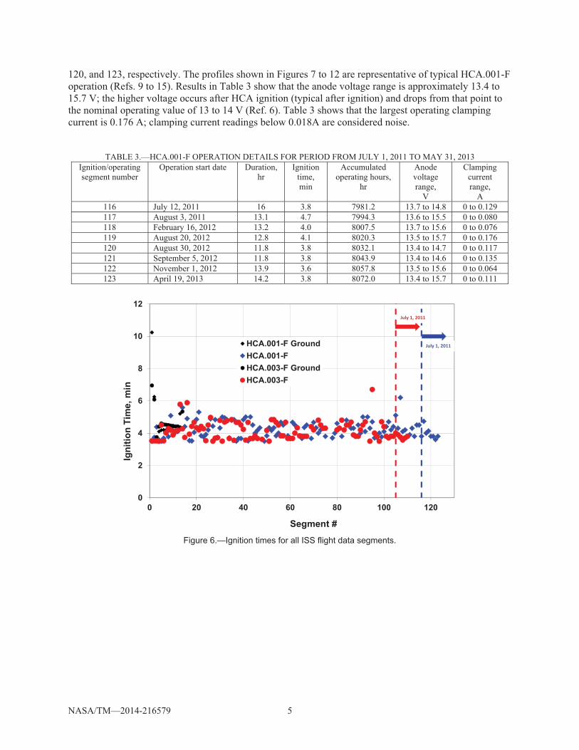
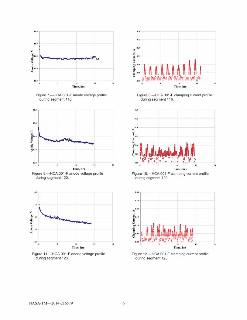
Operational details of HCA.001-F are presented in Table 3. During the time period from July 1, 2011 to May 31, 2013, HCA.001-F was ignited 8 times (segments 116-123) and operated for a total duration of 106.8 hr. For the flight HCAs, a “segment” is defined as the period of time between HCA ignition and until it is commanded off and the emission current reaches zero. At the end of segment 123, the total accumulated operating time was 8072 hr. HCA.001-F ignition times for segments 116-123 were between 3.6 and 4.7 min as presented in Figure 6 and Table 2. These ignition times are consistent with previous segments ignition times. Figures 7, 9, and 11 present the anode voltage profiles during segments 116, 120, and 123, respectively. Figures 8, 10, and 12 present the clamping current profiles during segments 116,
NASA/TM—2014-216579 5
120, and 123, respectively. The profiles shown in Figures 7 to 12 are representative of typical HCA.001-F operation (Refs. 9 to 15). Results in Table 3 show that the anode voltage range is approximately 13.4 to 15.7 V; the higher voltage occurs after HCA ignition (typical after ignition) and drops from that point to the nominal operating value of 13 to 14 V (Ref. 6). Table 3 shows that the largest operating clamping current is 0.176 A; clamping current readings below 0.018A are considered noise.
TABLE 3.—HCA.001-F OPERATION DETAILS FOR PERIOD FROM JULY 1, 2011 TO MAY 31, 2013 Ignition/operating segment number
Operation start date Duration,hr
Ignition time, min
Accumulated operating hours,
hr
Anode voltage range,
V
Clamping current range,
A 116 July 12, 2011 16 3.8 7981.2 13.7 to 14.8 0 to 0.129 117 August 3, 2011 13.1 4.7 7994.3 13.6 to 15.5 0 to 0.080 118 February 16, 2012 13.2 4.0 8007.5 13.7 to 15.6 0 to 0.076 119 August 20, 2012 12.8 4.1 8020.3 13.5 to 15.7 0 to 0.176 120 August 30, 2012 11.8 3.8 8032.1 13.4 to 14.7 0 to 0.117 121 September 5, 2012 11.8 3.8 8043.9 13.4 to 14.6 0 to 0.135 122 November 1, 2012 13.9 3.6 8057.8 13.5 to 15.6 0 to 0.064 123 April 19, 2013 14.2 3.8 8072.0 13.4 to 15.7 0 to 0.111
Figure 6.—Ignition times for all ISS flight data segments.
0
2
4
6
8
10
12
0 20 40 60 80 100 120
Igni
tion
Tim
e, m
in
Segment #
HCA.001-F GroundHCA.001-FHCA.003-F GroundHCA.003-F
July�1,�2011
July�1,�2011
NASA/TM—2014-216579 6
Figure 7.—HCA.001-F anode voltage profile during segment 116.
Figure 8.—HCA.001-F clamping current profile during segment 116.
Figure 9.—HCA.001-F anode voltage profile during segment 120.
Figure 10.—HCA.001-F clamping current profile during segment 120.
Figure 11.—HCA.001-F anode voltage profile during segment 123.
Figure 12.—HCA.001-F clamping current profile during segment 123.
NASA/TM—2014-216579 7
Hollow Cathode Assembly HCA.003-F on PCU FM02
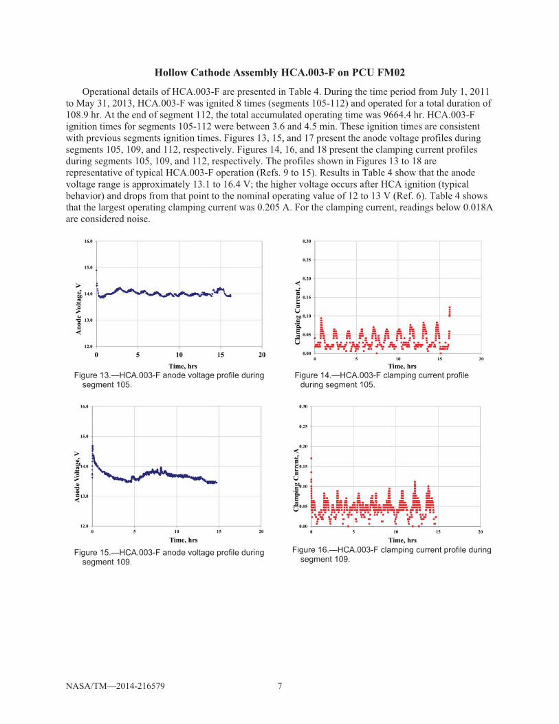
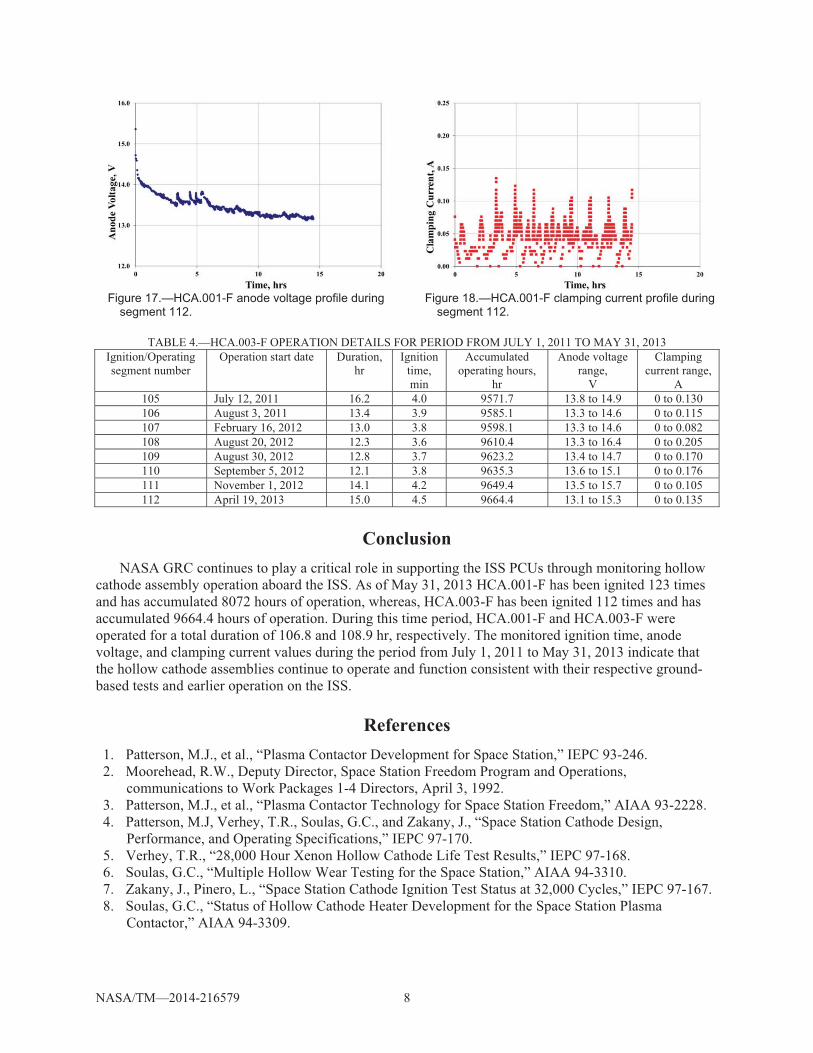
Operational details of HCA.003-F are presented in Table 4. During the time period from July 1, 2011 to May 31, 2013, HCA.003-F was ignited 8 times (segments 105-112) and operated for a total duration of 108.9 hr. At the end of segment 112, the total accumulated operating time was 9664.4 hr. HCA.003-F ignition times for segments 105-112 were between 3.6 and 4.5 min. These ignition times are consistent with previous segments ignition times. Figures 13, 15, and 17 present the anode voltage profiles during segments 105, 109, and 112, respectively. Figures 14, 16, and 18 present the clamping current profiles during segments 105, 109, and 112, respectively. The profiles shown in Figures 13 to 18 are representative of typical HCA.003-F operation (Refs. 9 to 15). Results in Table 4 show that the anode voltage range is approximately 13.1 to 16.4 V; the higher voltage occurs after HCA ignition (typical behavior) and drops from that point to the nominal operating value of 12 to 13 V (Ref. 6). Table 4 shows that the largest operating clamping current was 0.205 A. For the clamping current, readings below 0.018A are considered noise.
Figure 13.—HCA.003-F anode voltage profile during segment 105.
Figure 14.—HCA.003-F clamping current profile during segment 105.
Figure 15.—HCA.003-F anode voltage profile during segment 109.
Figure 16.—HCA.003-F clamping current profile during segment 109.
NASA/TM—2014-216579 8
Figure 17.—HCA.001-F anode voltage profile during segment 112.
Figure 18.—HCA.001-F clamping current profile during segment 112.
TABLE 4.—HCA.003-F OPERATION DETAILS FOR PERIOD FROM JULY 1, 2011 TO MAY 31, 2013
Ignition/Operating segment number
Operation start date Duration,hr
Ignition time, min
Accumulated operating hours,
hr
Anode voltage range,
V
Clamping current range,
A 105 July 12, 2011 16.2 4.0 9571.7 13.8 to 14.9 0 to 0.130 106 August 3, 2011 13.4 3.9 9585.1 13.3 to 14.6 0 to 0.115 107 February 16, 2012 13.0 3.8 9598.1 13.3 to 14.6 0 to 0.082 108 August 20, 2012 12.3 3.6 9610.4 13.3 to 16.4 0 to 0.205 109 August 30, 2012 12.8 3.7 9623.2 13.4 to 14.7 0 to 0.170 110 September 5, 2012 12.1 3.8 9635.3 13.6 to 15.1 0 to 0.176 111 November 1, 2012 14.1 4.2 9649.4 13.5 to 15.7 0 to 0.105 112 April 19, 2013 15.0 4.5 9664.4 13.1 to 15.3 0 to 0.135
Conclusion NASA GRC continues to play a critical role in supporting the ISS PCUs through monitoring hollow
cathode assembly operation aboard the ISS. As of May 31, 2013 HCA.001-F has been ignited 123 times and has accumulated 8072 hours of operation, whereas, HCA.003-F has been ignited 112 times and has accumulated 9664.4 hours of operation. During this time period, HCA.001-F and HCA.003-F were operated for a total duration of 106.8 and 108.9 hr, respectively. The monitored ignition time, anode voltage, and clamping current values during the period from July 1, 2011 to May 31, 2013 indicate that the hollow cathode assemblies continue to operate and function consistent with their respective ground-based tests and earlier operation on the ISS.
References 1. Patterson, M.J., et al., “Plasma Contactor Development for Space Station,” IEPC 93-246. 2. Moorehead, R.W., Deputy Director, Space Station Freedom Program and Operations,
communications to Work Packages 1-4 Directors, April 3, 1992. 3. Patterson, M.J., et al., “Plasma Contactor Technology for Space Station Freedom,” AIAA 93-2228. 4. Patterson, M.J, Verhey, T.R., Soulas, G.C., and Zakany, J., “Space Station Cathode Design,
Performance, and Operating Specifications,” IEPC 97-170. 5. Verhey, T.R., “28,000 Hour Xenon Hollow Cathode Life Test Results,” IEPC 97-168. 6. Soulas, G.C., “Multiple Hollow Wear Testing for the Space Station,” AIAA 94-3310. 7. Zakany, J., Pinero, L., “Space Station Cathode Ignition Test Status at 32,000 Cycles,” IEPC 97-167. 8. Soulas, G.C., “Status of Hollow Cathode Heater Development for the Space Station Plasma
Contactor,” AIAA 94-3309.
NASA/TM—2014-216579 9
9. Kamhawi, H., Patterson, M.J., and Dalton, P., “On the Operational Status of the International Space Station Plasma Contactor Hollow Cathodes,” AIAA 2009-5092.
10. Carpenter, C.B., “Comparison of On-Orbit and Ground Based Hollow Cathode Operation,” AIAA 2002-4098.
11. Carpenter, C.B., “Comparison of On-Orbit and Ground Based Hollow Cathode Operation,” AIAA 2003-5145.
12. Carpenter, C.B., “On the Operational Status of the ISS Plasma Contactor Hollow Cathodes,” AIAA 2004-3425.
13. Kamhawi, H., and Patterson, M.J., “On the Operational Status of the International Space Station Plasma Contactor Hollow Cathodes,” AIAA 2005-3676.
14. Kamhawi, H., and Patterson, M.J., “On the Operational Status of the International Space Station Plasma Contactor Hollow Cathodes,” AIAA 2007-5190.
15. Kamhawi, H., Patterson, M.J., and Dalton, P., “Update on the Operational Status of the International Space Station Plasma Contactor Hollow Cathodes,” AIAA 2011-5990.

NASA/TM—2014-216579 11
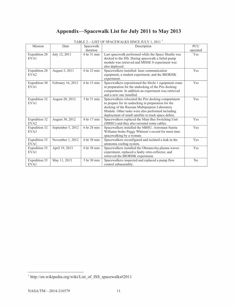
Appendix—Spacewalk List for July 2011 to May 2013
TABLE 2.—LIST OF SPACEWALKS SINCE JULY 1, 2011 1 Mission Date Spacewalk
duration Description PCU
operated Expedition 28 EVA1
July 12, 2011 6 hr 31 min Last spacewalk performed while the Space Shuttle was docked to the ISS. During spacewalk a failed pump module was retrieved and MISSE 8 experiment was also deployed.
Yes
Expedition 28 EVA2
August 3, 2011 6 hr 23 min Spacewalkers installed: laser communication equipment, a student experiment, and the BIORISK experiment.
Yes
Expedition 30 EVA1
February 16, 2012 6 hr 15 min Spacewalkers repositioned the Strela 1 equipment crane in preparation for the undocking of the Pirs docking compartment. In addition an experiment was retrieved and a new one installed.
Yes
Expedition 32 EVA1
August 20, 2012 5 hr 51 min Spacewalkers relocated the Pirs docking compartment to prepare for its undocking in preparation for the docking of the Russian Multipurpose Laboratory Module. Other tasks were also performed including deployment of small satellite to track space debris.
Yes
Expedition 32 EVA2
August 30, 2012 8 hr 17 min Spacewalkers replaced the Main Bus Switching Unit (MBSU) and they also rerouted some cables.
Yes
Expedition 32 EVA3
September 5, 2012 6 hr 28 min Spacewalkers installed the MBSU. Astronaut Sunita Williams broke Peggy Whitson’s record for most time spacewalking by a woman.
Yes
Expedition 33 EVA1
November 1, 2012 6 hr 38 min Spacewalkers reconfigured and isolated a leak in the ammonia cooling system.
Yes
Expedition 33 EVA1
April 19, 2013 6 hr 38 min Spacewalkers installed the Obstanovka plasma waves experiment, replaced a faulty retro-reflector, and retrieved the BIORISK experiment.
Yes
Expedition 35 EVA1
May 11, 2013 5 hr 30 min Spacewalkers inspected and replaced a pump flow control subassembly.
No
1 http://en.wikipedia.org/wiki/List_of_ISS_spacewalks#2011