Embed Size (px)
Citation preview
Operational Amplifiers
Brandon Borm
Shelley Nation
Chloe Milion

Outline
Introduction Background Fundamentals of Op-Amps Real vs. Ideal Applications

What is an Op-Amp
Low cost integrating circuit consisting of transistorsresistorscapacitors
Op-amps amplify an input signal using an external power supply

Uses for Op-Amps Op-Amps are commonly used for both linear and
nonlinear applications Linear
Amplifiers Summers Integrators Differentiators Filters (High, Low, and Band Pass)
Non-linear Comparators A/D converters

Vacuum Tube Op-Amps First op amps built in 1930’s-
1940’s Technically feedback amplifiers
due to only having one useable input
Used in WWII to help how to strike military targets Buffers, summers, differentiators,
inverters
Took ±300V to ± 100V to power
http://en.wikipedia.org/wiki/Image:K2-w_vaccuum_tube_op-amp.jpg1

Solid State Discrete Op-Amps Solid state op amps invented in
1960’sPossible due to invention of
silicon transistors and the IC Chip and discrete parts
Reduced power input to ±15V to ±10V
Packaging in small black boxes allowed for integration with a circuit

Monolithic Integrated Circuit Op-Amp First created in 1963
μA702 by Fairchild Semiconductor
μA741 created in 1968 Became widely used due to its ease
of use 8 pin, dual in-line package (DIP)
Further advancements include use of field effects transistors (FET), greater precision, faster response, and smaller packaging

Features of Op-Amps +Vin: non-inverting input
-Vin: inverting input
+Vs: positive source
-Vs: negative source
Vout: output voltage ON: Offset Null NC: Not Connected
Vout
+Vs
-Vs
+Vin
-Vin
+
-
ON
-Vin
+Vin
-Vs ON
Vout
+Vs
NC

Characteristics of Op-AmpsIdeal Op-Amp
Infinite open loop gain (GOL): Zero common mode gain
Infinite bandwidth: Range of frequencies
with non-zero gain
Real Op-Amp
Limited open loop gain: Decreases with increase
in frequency Non-zero common mode
gain
Limited Bandwidth: Gain becomes zero at
high frequencies

Characteristics of Op-AmpsIdeal Op-Amp
Infinite slew rate
Infinite input impedance No input current
Zero output impedance Infinite output current
Real Op-Amp
Finite slew rate
Large input impedance Small input current
Non-zero output impedance Limited output current

Summary of Characteristics
Parameter Ideal Op-Amp Typical Op-Amp
GOL ∞ 105 - 109
Common Mode Gain
0 10-5
Bandwidth ∞ 1-20 MHz
Input Impedance
∞ 106 Ω (bipolar)
109-1012 Ω (FET)
Output Impedance
0 100-1000 Ω

Ideal Op-Amp
Active device Infinite open loop gain Infinite input impedance Zero output impedance
+
-
+Vs
-Vs
Vdiff
iin = 0A
Vout = Vdiff x Gopenloop

Negative Feedback
Vout is a linear function of the input voltage
Zin = infinity Iin=0A Vdiff=0V
Modelisation of basic mathematical operation

Non Inverting Circuit
+
-
R1 R2
+Vs
-Vs
iin = 0A
Vdiff = 0VVin
Vout
0A
V- V- - Vout
i
(1) V- - Vout = R2 x i
(2) V- = - R1 x i
V- = V+ = Vin
(2) i = -Vin/R1
(1) Vin – Vout = -Vin x R1/R2
Vout = (1 + R1/R2) x Vin
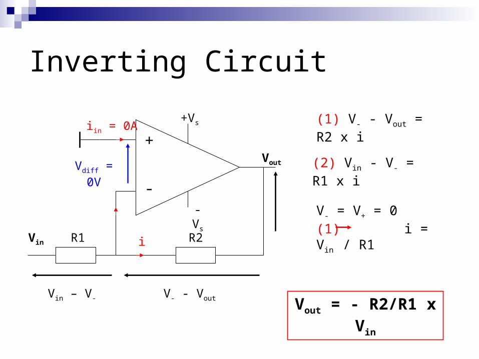
Inverting Circuit
+
-
R1 R2
+Vs
-Vs
Vdiff = 0V
Vin
Vout
iin = 0A
i
V- - VoutVin – V-
(1) V- - Vout = R2 x i
(2) Vin - V- = R1 x i
V- = V+ = 0(1) i = Vin / R1
Vout = - R2/R1 x Vin

Follower Circuit
Vin Vout
+ Vs
- Vs

Summing Op-Amp• Adds analog signals
f
out
R
VV
R
VV
R
VV
R
VV
3
3
2
2
1
1
3
3
2
2
1
1
R
V
R
V
R
VRV foutSolving for Vout:
Ohm’s Law:

Summing Op-Amp

Difference Op-Amps• Subtracts analog signals
1
1
32
124
413
)(V
R
RV
RRR
RRRVout
• Output voltage is proportional to difference between input voltages:

Difference Op-Amp

Integrator Op-Amps•Similar layout to inverting op-amp, but replace feedback resistor with a capacitor
•A constant input signal generates a certain rate of change in output voltage
• Smoothes signals over time
t
ininitialoutfinalout dtVRC
VV0
,,
1
•Output voltage is proportional to the integral of the input voltage:

Integrator Op-Amp

Differentiating Op-Amp•Similar to inverting op-amp, but input resistor is replaced with a capacitor
•Accentuates noise over time
dt
dVRCV in
out • Output signal is scaled derivative of input signal:

Differentiating Op-Amp
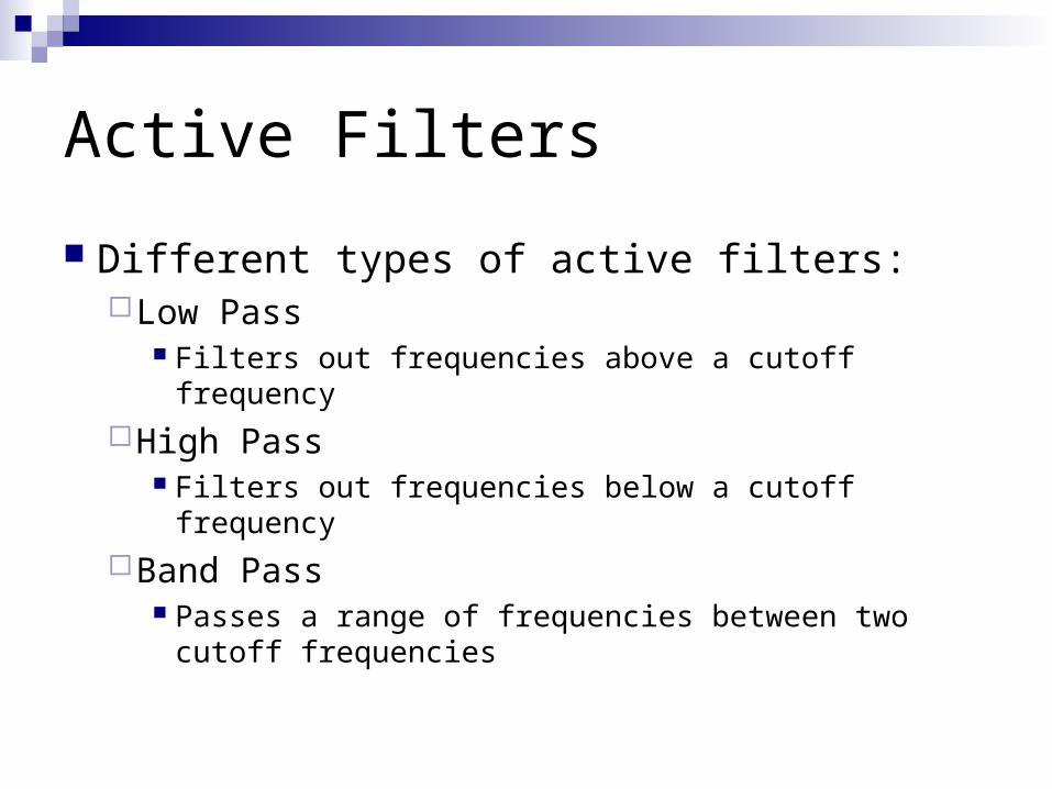
Active Filters
Different types of active filters:Low Pass
Filters out frequencies above a cutoff frequency
High Pass Filters out frequencies below a cutoff frequency
Band Pass Passes a range of frequencies between two cutoff
frequencies

Active Low-Pass Filter
Cutoff frequency:CRc2
1
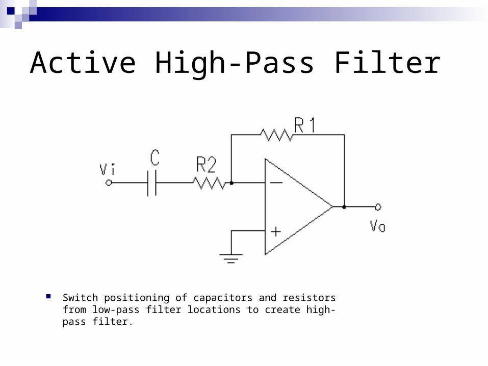
Active High-Pass Filter
Switch positioning of capacitors and resistors from low-pass filter locations to create high-pass filter.

Active Band-Pass Filter
Created by connecting output of a high-pass filter to the input of a low-pass filter or vice versa.
Also can create using only 1 op-amp with feedback and input capacitors
No negative feedback
Vout is a non-linear function of the differential input voltage V+ - V-
V+ - V- = Vdiff
Vout = sign(Vdiff) x Vs
Binary logic and oscillator

Comparator
+
-
+Vs
-Vs
iin = 0A
Vdiff
V+
V-
Vout
0V
+ Vs
Vout ( volts )
Vdiff
- Vs

Comparator

Questions?

References
“Operational Amplifiers.” http://en.wikipedia.org/wiki/Op_amp
“Real vs. Ideal Op Amp.” http://hyperphysics.phy-astr.gsu.edu/hbase/electronic/opamp.html#c4
“741 Op Amp Tutorial.” http://www.uoguelph.ca/~antoon/gadgets/741/741.html
“Op Amp History.” Analog Devices. http://www.analog.com/library/analogDialogue/archives/39-05/Web_ChH_final.pdf