Embed Size (px)
Citation preview
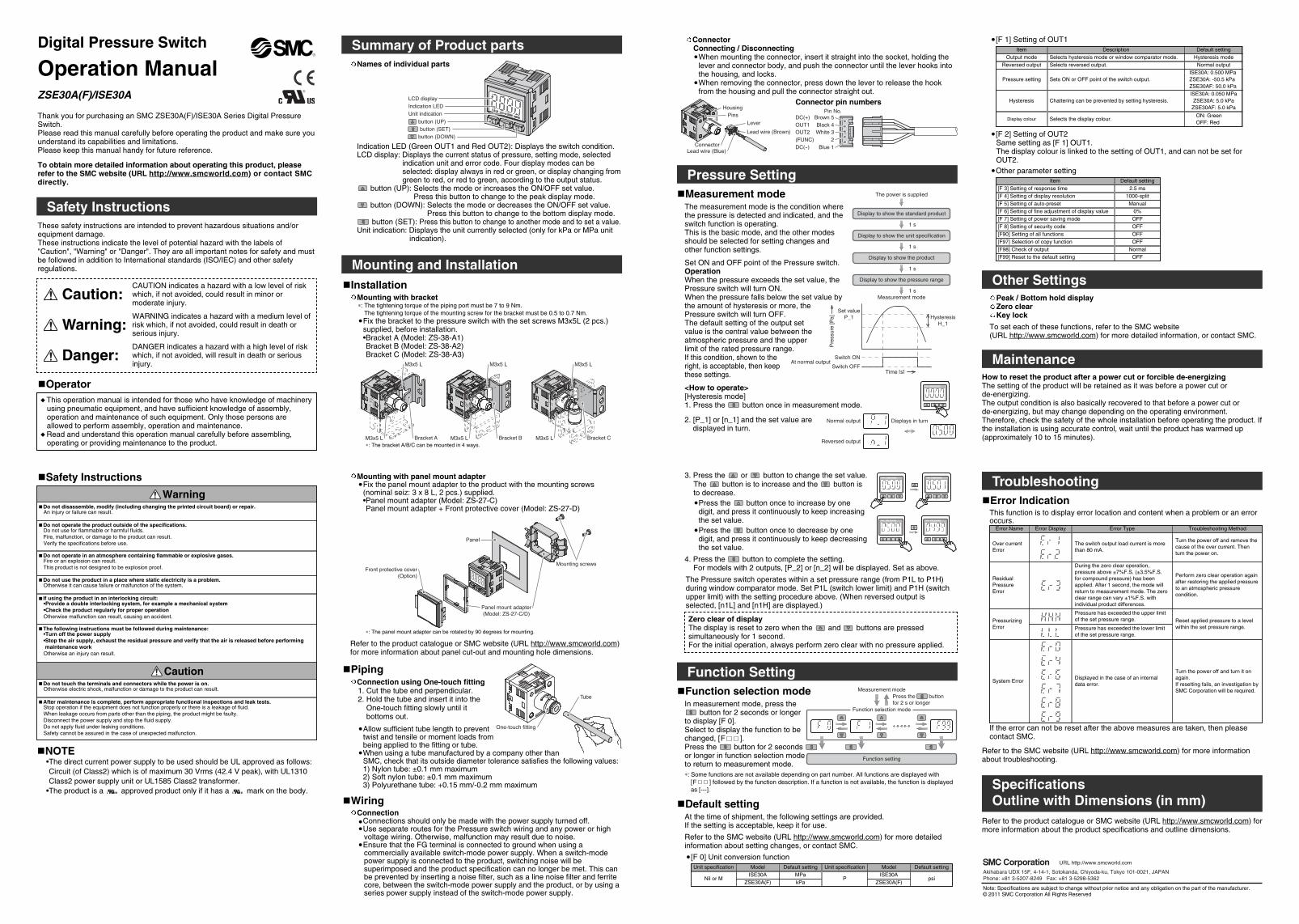
Pressure Setting
Set ON and OFF point of the Pressure switch.OperationWhen the pressure exceeds the set value, thePressure switch will turn ON.When the pressure falls below the set value bythe amount of hysteresis or more, thePressure switch will turn OFF.The default setting of the output setvalue is the central value between theatmospheric pressure and the upperlimit of the rated pressure range.If this condition, shown to theright, is acceptable, then keepthese settings.
<How to operate>[Hysteresis mode]1. Press the button once in measurement mode.
2. [P_1] or [n_1] and the set value aredisplayed in turn.
ConnectorConnecting / DisconnectingWhen mounting the connector, insert it straight into the socket, holding thelever and connector body, and push the connector until the lever hooks intothe housing, and locks.When removing the connector, press down the lever to release the hookfrom the housing and pull the connector straight out.
Digital Pressure Switch
Operation ManualZSE30A(F)/ISE30A
Thank you for purchasing an SMC ZSE30A(F)/ISE30A Series Digital PressureSwitch.Please read this manual carefully before operating the product and make sure youunderstand its capabilities and limitations.Please keep this manual handy for future reference.
To obtain more detailed information about operating this product, pleaserefer to the SMC website (URL http://www.smcworld.com) or contact SMCdirectly.
Safety InstructionsThese safety instructions are intended to prevent hazardous situations and/orequipment damage.These instructions indicate the level of potential hazard with the labels of"Caution", "Warning" or "Danger". They are all important notes for safety and mustbe followed in addition to International standards (ISO/IEC) and other safetyregulations.
Function Setting
Default settingAt the time of shipment, the following settings are provided.If the setting is acceptable, keep it for use.
Refer to the SMC website (URL http://www.smcworld.com) for more detailedinformation about setting changes, or contact SMC.
[F 0] Unit conversion function
[F 1] Setting of OUT1
[F 2] Setting of OUT2Same setting as [F 1] OUT1.The display colour is linked to the setting of OUT1, and can not be set forOUT2.Other parameter setting
Item Default setting[F 3] Setting of response time 2.5 ms[F 4] Setting of display resolution 1000-split[F 5] Setting of auto-preset Manual
0%[F 6] Setting of fine adjustment of display valueOFF[F 7] Setting of power saving modeOFF[F 8] Setting of security codeOFF[F90] Setting of all functionsOFF[F97] Selection of copy functionNormal[F98] Check of outputOFF[F99] Reset to the default setting
Item DescriptionOutput mode Selects hysteresis mode or window comparator mode.
Reversed output Selects reversed output.
Pressure setting Sets ON or OFF point of the switch output.
Default setting
Hysteresis Chattering can be prevented by setting hysteresis.
Hysteresis mode
ISE30A: 0.500 MPaZSE30A: -50.5 kPaZSE30AF: 50.0 kPa
Normal output
ISE30A: 0.050 MPaZSE30A: 5.0 kPaZSE30AF: 5.0 kPa
Unit specification Model
Nil or MISE30A
ZSE30A(F)
Default setting
PISE30AMPa
kPa ZSE30A(F)
Measurement modeThe measurement mode is the condition wherethe pressure is detected and indicated, and theswitch function is operating.This is the basic mode, and the other modesshould be selected for setting changes andother function settings.
Measurement mode
1 s
1 s
1 s
Display to show the unit specification
Display to show the product
The power is supplied
1 s
Display to show the standard product
Display to show the pressure range
Indication LED (Green OUT1 and Red OUT2): Displays the switch condition.LCD display: Displays the current status of pressure, setting mode, selected
indication unit and error code. Four display modes can beselected: display always in red or green, or display changing fromgreen to red, or red to green, according to the output status.
button (UP): Selects the mode or increases the ON/OFF set value.Press this button to change to the peak display mode.
button (DOWN): Selects the mode or decreases the ON/OFF set value.Press this button to change to the bottom display mode.
button (SET): Press this button to change to another mode and to set a value.Unit indication: Displays the unit currently selected (only for kPa or MPa unit
indication).
Summary of Product parts
InstallationMounting with bracket∗: The tightening torque of the piping port must be 7 to 9 Nm.The tightening torque of the mounting screw for the bracket must be 0.5 to 0.7 Nm.Fix the bracket to the pressure switch with the set screws M3x5L (2 pcs.)supplied, before installation.•Bracket A (Model: ZS-38-A1)Bracket B (Model: ZS-38-A2)Bracket C (Model: ZS-38-A3)
Mounting and Installation
Names of individual parts
Connector pin numbers
psi
LCD displayIndication LED
button (UP)button (SET)
button (DOWN)
Unit indication
M3x5 L Bracket B
M3x5 L
Bracket AM3x5 L
M3x5 L
M3x5 L Bracket C
M3x5 L
DC(+) Brown 5Pin No.
OUT1 Black 4OUT2 White 3(FUNC) 2DC(-) Blue 1
HousingPins
LeverLead wire (Brown)
ConnectorLead wire (Blue)
Displays in turnNormal output
Reversed output
Display colour Selects the display colour.ON: GreenOFF: Red
CAUTION indicates a hazard with a low level of riskwhich, if not avoided, could result in minor ormoderate injury.
OperatorThis operation manual is intended for those who have knowledge of machineryusing pneumatic equipment, and have sufficient knowledge of assembly,operation and maintenance of such equipment. Only those persons areallowed to perform assembly, operation and maintenance.Read and understand this operation manual carefully before assembling,operating or providing maintenance to the product.
Caution:
Warning:
Danger:
WARNING indicates a hazard with a medium level ofrisk which, if not avoided, could result in death orserious injury.
DANGER indicates a hazard with a high level of riskwhich, if not avoided, will result in death or seriousinjury.
Safety Instructions
Do not disassemble, modify (including changing the printed circuit board) or repair.An injury or failure can result.
Do not operate in an atmosphere containing flammable or explosive gases.Fire or an explosion can result.This product is not designed to be explosion proof.
Do not use the product in a place where static electricity is a problem.Otherwise it can cause failure or malfunction of the system.
NOTE•The direct current power supply to be used should be UL approved as follows:Circuit (of Class2) which is of maximum 30 Vrms (42.4 V peak), with UL1310Class2 power supply unit or UL1585 Class2 transformer.•The product is a approved product only if it has a mark on the body.
If using the product in an interlocking circuit:•Provide a double interlocking system, for example a mechanical system•Check the product regularly for proper operationOtherwise malfunction can result, causing an accident.
The following instructions must be followed during maintenance:•Turn off the power supply•Stop the air supply, exhaust the residual pressure and verify that the air is released before performingmaintenance workOtherwise an injury can result.
After maintenance is complete, perform appropriate functional inspections and leak tests.Stop operation if the equipment does not function properly or there is a leakage of fluid.When leakage occurs from parts other than the piping, the product might be faulty.Disconnect the power supply and stop the fluid supply.Do not apply fluid under leaking conditions.Safety cannot be assured in the case of unexpected malfunction.
Do not touch the terminals and connectors while the power is on.Otherwise electric shock, malfunction or damage to the product can result.
Do not operate the product outside of the specifications.Do not use for flammable or harmful fluids.Fire, malfunction, or damage to the product can result.Verify the specifications before use.
The Pressure switch operates within a set pressure range (from P1L to P1H)during window comparator mode. Set P1L (switch lower limit) and P1H (switchupper limit) with the setting procedure above. (When reversed output isselected, [n1L] and [n1H] are displayed.)
Zero clear of displayThe display is reset to zero when the and buttons are pressedsimultaneously for 1 second.For the initial operation, always perform zero clear with no pressure applied.
Other SettingsPeak / Bottom hold displayZero clearKey lock
To set each of these functions, refer to the SMC website(URL http://www.smcworld.com) for more detailed information, or contact SMC.
MaintenanceHow to reset the product after a power cut or forcible de-energizingThe setting of the product will be retained as it was before a power cut orde-energizing.The output condition is also basically recovered to that before a power cut orde-energizing, but may change depending on the operating environment.Therefore, check the safety of the whole installation before operating the product. Ifthe installation is using accurate control, wait until the product has warmed up(approximately 10 to 15 minutes).
Troubleshooting
The switch output load current is morethan 80 mA.
Turn the power off and remove thecause of the over current. Thenturn the power on.
Error IndicationThis function is to display error location and content when a problem or an erroroccurs.
ResidualPressureError
PressurizingError
System Error
During the zero clear operation,pressure above ±7%F.S. (±3.5%F.S.for compound pressure) has beenapplied. After 1 second, the mode willreturn to measurement mode. The zeroclear range can vary ±1%F.S. withindividual product differences.
Perform zero clear operation againafter restoring the applied pressureto an atmospheric pressurecondition.
Pressure has exceeded the upper limitof the set pressure range.
Displayed in the case of an internaldata error.
Reset applied pressure to a levelwithin the set pressure range.
Turn the power off and turn it onagain.If resetting fails, an investigation bySMC Corporation will be required.
If the error can not be reset after the above measures are taken, then pleasecontact SMC.
Note: Specifications are subject to change without prior notice and any obligation on the part of the manufacturer.© 2011 SMC Corporation All Rights Reserved
Pressure has exceeded the lower limitof the set pressure range.
Akihabara UDX 15F, 4-14-1, Sotokanda, Chiyoda-ku, Tokyo 101-0021, JAPANPhone: +81 3-5207-8249 Fax: +81 3-5298-5362
URL http://www.smcworld.com
Error Name Error Display Error Type Troubleshooting Method
Over currentError
3. Press the or button to change the set value.The button is to increase and the button isto decrease.Press the button once to increase by onedigit, and press it continuously to keep increasingthe set value.Press the button once to decrease by onedigit, and press it continuously to keep decreasingthe set value.
4. Press the button to complete the setting.For models with 2 outputs, [P_2] or [n_2] will be displayed. Set as above.
Function selection modeIn measurement mode, press the
button for 2 seconds or longerto display [F 0].Select to display the function to bechanged, [F ].Press the button for 2 secondsor longer in function selection modeto return to measurement mode.
Measurement mode
Function selection mode
Function setting
Press the buttonfor 2 s or longer
∗: Some functions are not available depending on part number. All functions are displayed with [F ] followed by the function description. If a function is not available, the function is displayedas [---].
Unit specification Model Default setting
Warning
Caution
Switch ONAt normal output
Switch OFF
Set valueP_1 Hysteresis
H_1
Time [s]
Pre
ssur
e [P
a]
∗: The bracket A/B/C can be mounted in 4 ways.
PipingConnection using One-touch fitting1. Cut the tube end perpendicular.2. Hold the tube and insert it into theOne-touch fitting slowly until itbottoms out.
Allow sufficient tube length to preventtwist and tensile or moment loads frombeing applied to the fitting or tube.When using a tube manufactured by a company other thanSMC, check that its outside diameter tolerance satisfies the following values:1) Nylon tube: ±0.1 mm maximum2) Soft nylon tube: ±0.1 mm maximum3) Polyurethane tube: +0.15 mm/-0.2 mm maximum
WiringConnectionConnections should only be made with the power supply turned off.Use separate routes for the Pressure switch wiring and any power or highvoltage wiring. Otherwise, malfunction may result due to noise.Ensure that the FG terminal is connected to ground when using acommercially available switch-mode power supply. When a switch-modepower supply is connected to the product, switching noise will besuperimposed and the product specification can no longer be met. This canbe prevented by inserting a noise filter, such as a line noise filter and ferritecore, between the switch-mode power supply and the product, or by using aseries power supply instead of the switch-mode power supply.
Mounting with panel mount adapterFix the panel mount adapter to the product with the mounting screws(nominal seiz: 3 x 8 L, 2 pcs.) supplied.•Panel mount adapter (Model: ZS-27-C)Panel mount adapter + Front protective cover (Model: ZS-27-D)
Panel
Front protective cover(Option)
Panel mount adapter(Model: ZS-27-C/D)
Mounting screws
Tube
One-touch fitting
∗: The panel mount adapter can be rotated by 90 degrees for mounting.
SpecificationsOutline with Dimensions (in mm)
Refer to the product catalogue or SMC website (URL http://www.smcworld.com) formore information about the product specifications and outline dimensions.
Refer to the product catalogue or SMC website (URL http://www.smcworld.com)for more information about panel cut-out and mounting hole dimensions.
Refer to the SMC website (URL http://www.smcworld.com) for more informationabout troubleshooting.