Embed Size (px)
Citation preview
General
1
Function of Each Components
2
Operation Method (JLN-740A/741A)
3
Menu Settings and Configurations (JLN-740A/741A)
4
Operation Method (JLN-740N/741N)
5
Menu Settings and Configurations (JLN-740N/741N)
6
Operation Method (Option)
7
Setting by Using Menus (Option)
8
Installation Method
9
Maintenance and Inspection
10
After-Sales Service
11
Disposal
12
Specification
13
Menu list APP A
Installation Drawings APP B
Error due to the deviation from the irradiation angle reference value
APP C
Spare Parts List APP D
JLN-740A/740N JLN-741A/741N DOPPLER LOG
Instruction Manual


i
Safety Cautions
Cautions for High Voltage High voltage of hundreds volts is used inside this equipment. Touching a component inside the unit is very dangerous. Any person other than specialized maintenance staffs should not maintain, inspect, or adjust the unit. High voltages on the order of tens of thousand volts are most likely to cause instant deaths from electrical shocks. At times, even voltages on the order of several hundred volts could lead to electrocution. To defend against electrical shock hazards, do not put your hand into the inside of apparatus. When you put in a hand unavoidably in case of urgent, it is strongly suggested to turn off the power switch and allow the capacitors, etc. to discharge with a wire having its one end positively grounded to remove residual charges. Before you put your hand into the inside of apparatus, make sure that internal parts are no longer charged. Extra protection is ensured by wearing dry cotton gloves at this time. Another important precaution to observe is to keep one hand in your pocket at a time, instead of using both hands at the same time. It is also important to select a secure footing to work on, as the secondary effects of electrical shock hazards can be more serious. In the event of electrical shocks, disinfect the burnt site completely and obtain medical care immediately.
Precautions for Rescue of Victim of Electric Shock
When a victim of electric shock is found, turn off the power source and ground the circuit immediately. If this is impossible, move the victim away from the unit as quick as possible without touching him or her with bare hands. He or she can safely be moved if an insulating material such as dry wood plate or cloth is used. It is necessary to perform first aid immediately. Breathing may stop if current flows through the respiration center of brain due to electric shock. If the electric shock is not large, breathing can be restored by artificial respiration. A victim of electric shock looks pale and his or her pulse may become very weak or stop, resulting in unconsciousness and rigidity at worst.
7ZPNA3208
ii
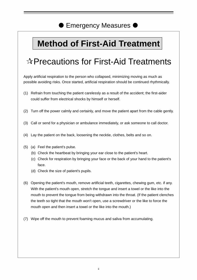
Emergency Measures
Method of First-Aid Treatment
Precautions for First-Aid Treatments
Apply artificial respiration to the person who collapsed, minimizing moving as much as possible avoiding risks. Once started, artificial respiration should be continued rhythmically.
(1) Refrain from touching the patient carelessly as a result of the accident; the first-aider
could suffer from electrical shocks by himself or herself. (2) Turn off the power calmly and certainly, and move the patient apart from the cable gently. (3) Call or send for a physician or ambulance immediately, or ask someone to call doctor. (4) Lay the patient on the back, loosening the necktie, clothes, belts and so on. (5) (a) Feel the patient's pulse.
(b) Check the heartbeat by bringing your ear close to the patient's heart. (c) Check for respiration by bringing your face or the back of your hand to the patient's
face. (d) Check the size of patient's pupils.
(6) Opening the patient's mouth, remove artificial teeth, cigarettes, chewing gum, etc. if any. With the patient's mouth open, stretch the tongue and insert a towel or the like into the mouth to prevent the tongue from being withdrawn into the throat. (If the patient clenches the teeth so tight that the mouth won't open, use a screwdriver or the like to force the mouth open and then insert a towel or the like into the mouth.)
(7) Wipe off the mouth to prevent foaming mucus and saliva from accumulating.
iii
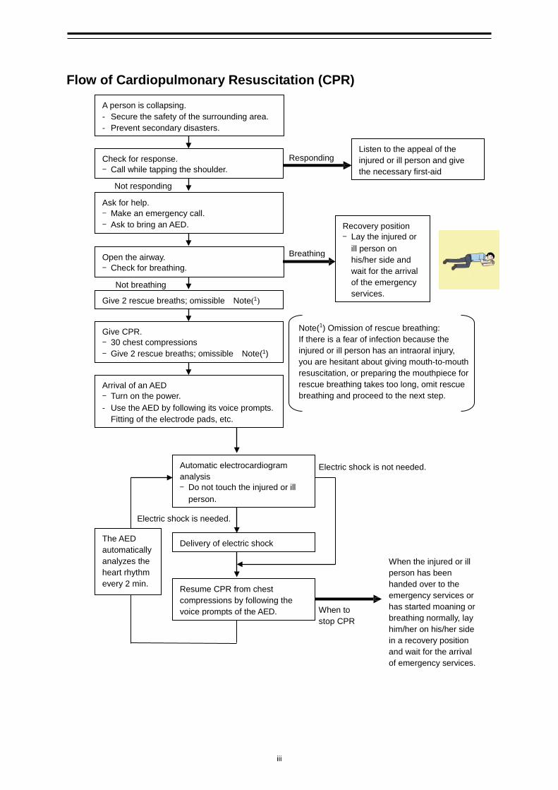
Flow of Cardiopulmonary Resuscitation (CPR)
A person is collapsing. - Secure the safety of the surrounding area. - Prevent secondary disasters.
Check for response. - Call while tapping the shoulder.
Breathing
Recovery position - Lay the injured or
ill person on his/her side and wait for the arrival of the emergency services.
Not responding
Ask for help. - Make an emergency call. - Ask to bring an AED.
Listen to the appeal of the injured or ill person and give the necessary first-aid
Responding
Not breathing
Give 2 rescue breaths; omissible Note(1)
Give CPR. - 30 chest compressions - Give 2 rescue breaths; omissible Note(1)
Note(1) Omission of rescue breathing: If there is a fear of infection because the injured or ill person has an intraoral injury, you are hesitant about giving mouth-to-mouth resuscitation, or preparing the mouthpiece for rescue breathing takes too long, omit rescue breathing and proceed to the next step.
Open the airway. - Check for breathing.
Arrival of an AED
- Turn on the power. - Use the AED by following its voice prompts. Fitting of the electrode pads, etc.
Automatic electrocardiogram analysis - Do not touch the injured or ill
person.
Electric shock is needed.
Electric shock is not needed.
Delivery of electric shock
Resume CPR from chest compressions by following the voice prompts of the AED.
When the injured or ill person has been handed over to the emergency services or has started moaning or breathing normally, lay him/her on his/her side in a recovery position and wait for the arrival of emergency services.
When to stop CPR
A person is collapsing. - Secure the safety of the surrounding area. - Prevent secondary disasters.
The AED automatically analyzes the heart rhythm every 2 min.
iv
Specific Procedures for Cardiopulmonary Resuscitation (CPR)
1. Check the scene for safety to prevent secondary disasters a) Do not touch the injured or ill person in panic when an accident has occurred. (Doing so may
cause electric shock to the first-aiders.)
b) Do not panic and be sure to turn off the power. Then, gently move the injured or ill person to a
safe place away from the electrical circuit.
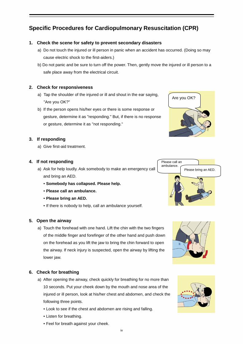
2. Check for responsiveness
a) Tap the shoulder of the injured or ill and shout in the ear saying,
"Are you OK?"
b) If the person opens his/her eyes or there is some response or
gesture, determine it as "responding." But, if there is no response
or gesture, determine it as "not responding."
3. If responding
a) Give first-aid treatment.
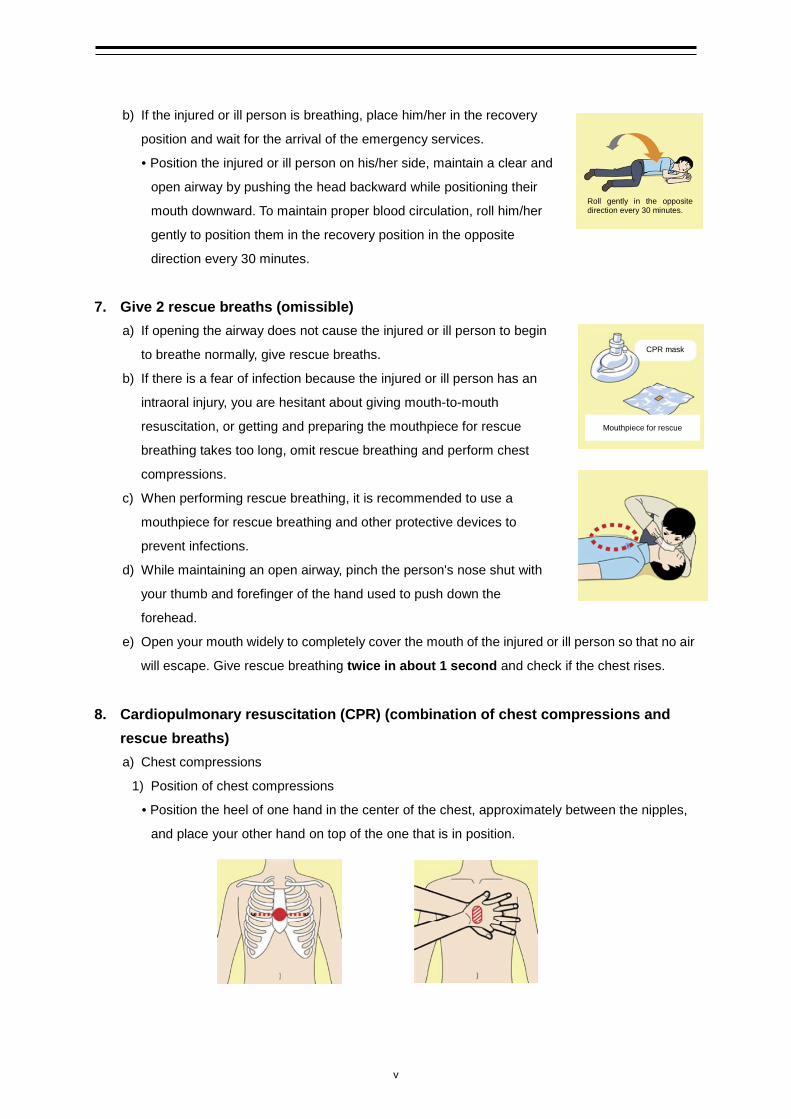
4. If not responding
a) Ask for help loudly. Ask somebody to make an emergency call
and bring an AED.
• Somebody has collapsed. Please help.
• Please call an ambulance.
• Please bring an AED.
• If there is nobody to help, call an ambulance yourself.
5. Open the airway a) Touch the forehead with one hand. Lift the chin with the two fingers
of the middle finger and forefinger of the other hand and push down
on the forehead as you lift the jaw to bring the chin forward to open
the airway. If neck injury is suspected, open the airway by lifting the
lower jaw.
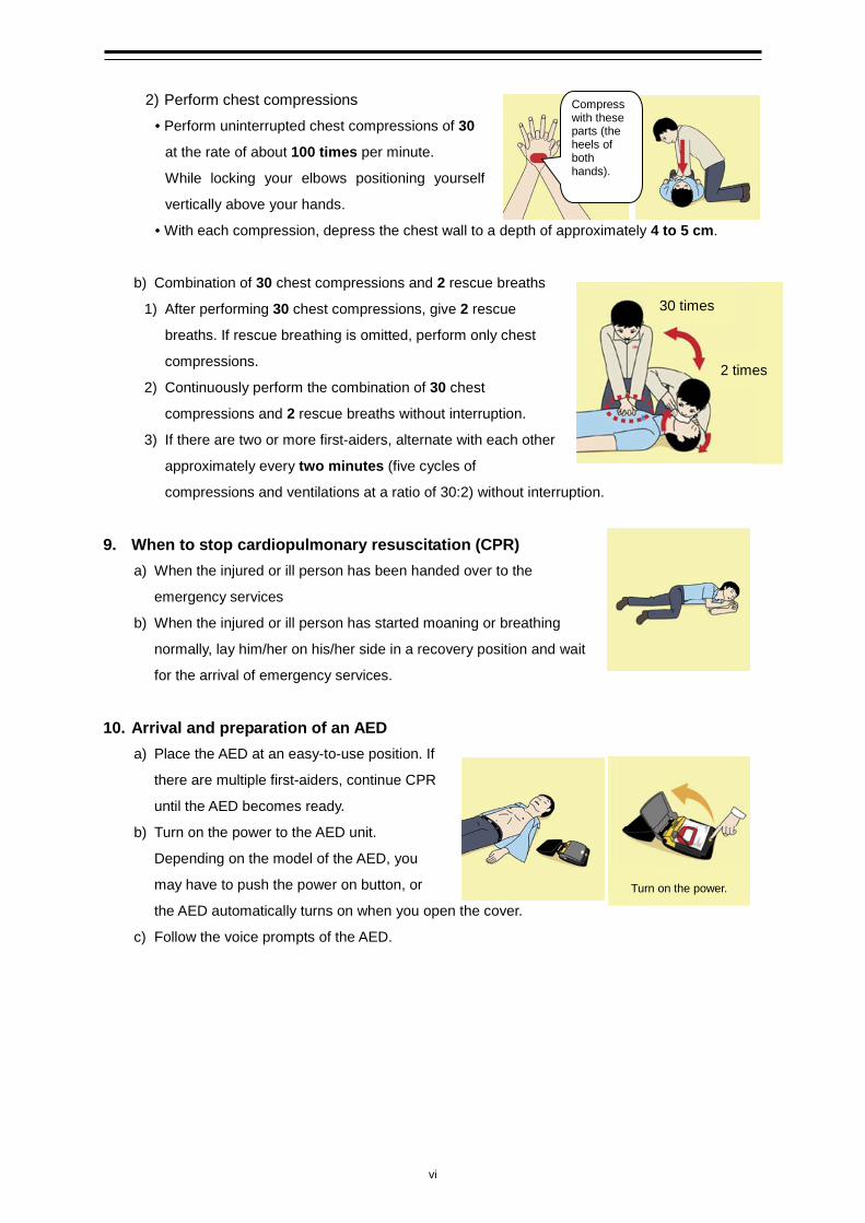
6. Check for breathing a) After opening the airway, check quickly for breathing for no more than
10 seconds. Put your cheek down by the mouth and nose area of the
injured or ill person, look at his/her chest and abdomen, and check the
following three points.
• Look to see if the chest and abdomen are rising and falling.
• Listen for breathing.
• Feel for breath against your cheek.
Are you OK?
Please call an ambulance.
Please bring an AED.
v
b) If the injured or ill person is breathing, place him/her in the recovery
position and wait for the arrival of the emergency services.
• Position the injured or ill person on his/her side, maintain a clear and
open airway by pushing the head backward while positioning their
mouth downward. To maintain proper blood circulation, roll him/her
gently to position them in the recovery position in the opposite
direction every 30 minutes.
7. Give 2 rescue breaths (omissible) a) If opening the airway does not cause the injured or ill person to begin
to breathe normally, give rescue breaths.
b) If there is a fear of infection because the injured or ill person has an
intraoral injury, you are hesitant about giving mouth-to-mouth
resuscitation, or getting and preparing the mouthpiece for rescue
breathing takes too long, omit rescue breathing and perform chest
compressions.
c) When performing rescue breathing, it is recommended to use a
mouthpiece for rescue breathing and other protective devices to
prevent infections.
d) While maintaining an open airway, pinch the person's nose shut with
your thumb and forefinger of the hand used to push down the
forehead.
e) Open your mouth widely to completely cover the mouth of the injured or ill person so that no air
will escape. Give rescue breathing twice in about 1 second and check if the chest rises.
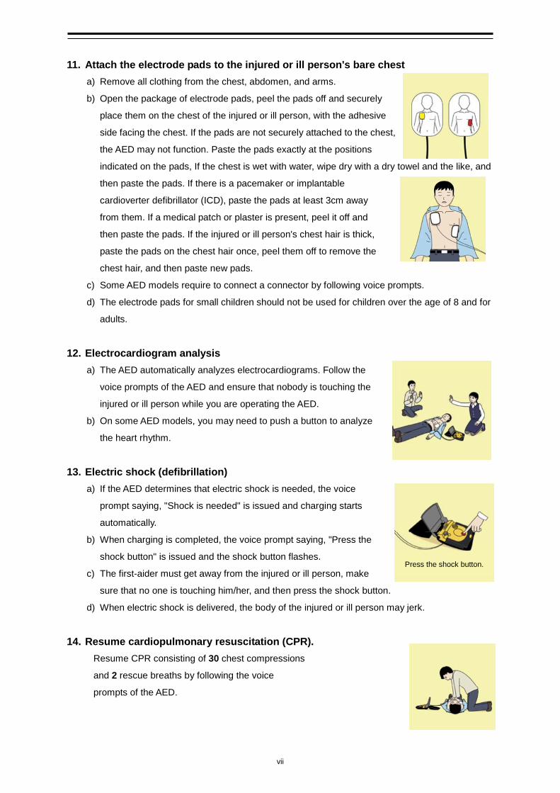
8. Cardiopulmonary resuscitation (CPR) (combination of chest compressions and rescue breaths) a) Chest compressions
1) Position of chest compressions
• Position the heel of one hand in the center of the chest, approximately between the nipples,
and place your other hand on top of the one that is in position.
Roll gently in the opposite direction every 30 minutes.
CPR mask
Mouthpiece for rescue
vi
2) Perform chest compressions
• Perform uninterrupted chest compressions of 30
at the rate of about 100 times per minute.
While locking your elbows positioning yourself
vertically above your hands.
• With each compression, depress the chest wall to a depth of approximately 4 to 5 cm.
b) Combination of 30 chest compressions and 2 rescue breaths
1) After performing 30 chest compressions, give 2 rescue
breaths. If rescue breathing is omitted, perform only chest
compressions.
2) Continuously perform the combination of 30 chest
compressions and 2 rescue breaths without interruption.
3) If there are two or more first-aiders, alternate with each other
approximately every two minutes (five cycles of
compressions and ventilations at a ratio of 30:2) without interruption.
9. When to stop cardiopulmonary resuscitation (CPR)
a) When the injured or ill person has been handed over to the
emergency services
b) When the injured or ill person has started moaning or breathing
normally, lay him/her on his/her side in a recovery position and wait
for the arrival of emergency services.
10. Arrival and preparation of an AED a) Place the AED at an easy-to-use position. If
there are multiple first-aiders, continue CPR
until the AED becomes ready.
b) Turn on the power to the AED unit.
Depending on the model of the AED, you
may have to push the power on button, or
the AED automatically turns on when you open the cover.
c) Follow the voice prompts of the AED.
30 times
Compress with these parts (the heels of both hands).
2 times
Turn on the power.
vii
11. Attach the electrode pads to the injured or ill person's bare chest a) Remove all clothing from the chest, abdomen, and arms.
b) Open the package of electrode pads, peel the pads off and securely
place them on the chest of the injured or ill person, with the adhesive
side facing the chest. If the pads are not securely attached to the chest,
the AED may not function. Paste the pads exactly at the positions
indicated on the pads, If the chest is wet with water, wipe dry with a dry towel and the like, and
then paste the pads. If there is a pacemaker or implantable
cardioverter defibrillator (ICD), paste the pads at least 3cm away
from them. If a medical patch or plaster is present, peel it off and
then paste the pads. If the injured or ill person's chest hair is thick,
paste the pads on the chest hair once, peel them off to remove the
chest hair, and then paste new pads.
c) Some AED models require to connect a connector by following voice prompts.
d) The electrode pads for small children should not be used for children over the age of 8 and for
adults.
12. Electrocardiogram analysis
a) The AED automatically analyzes electrocardiograms. Follow the
voice prompts of the AED and ensure that nobody is touching the
injured or ill person while you are operating the AED.
b) On some AED models, you may need to push a button to analyze
the heart rhythm.
13. Electric shock (defibrillation)
a) If the AED determines that electric shock is needed, the voice
prompt saying, "Shock is needed" is issued and charging starts
automatically.
b) When charging is completed, the voice prompt saying, "Press the
shock button" is issued and the shock button flashes.
c) The first-aider must get away from the injured or ill person, make
sure that no one is touching him/her, and then press the shock button.
d) When electric shock is delivered, the body of the injured or ill person may jerk.
14. Resume cardiopulmonary resuscitation (CPR). Resume CPR consisting of 30 chest compressions
and 2 rescue breaths by following the voice
prompts of the AED.
Press the shock button.
viii
15. Automatic electrocardiogram analysis a) When 2 minutes have elapsed since you resumed cardiopulmonary resuscitation (CPR), the
AED automatically analyzes the electrocardiogram.
b) If you suspended CPR by following voice prompts and AED voice prompt informs you that
shock is needed, give electric shock again by following the voice prompts.
If AED voice prompt informs you that no shock is needed, immediately resume CPR.
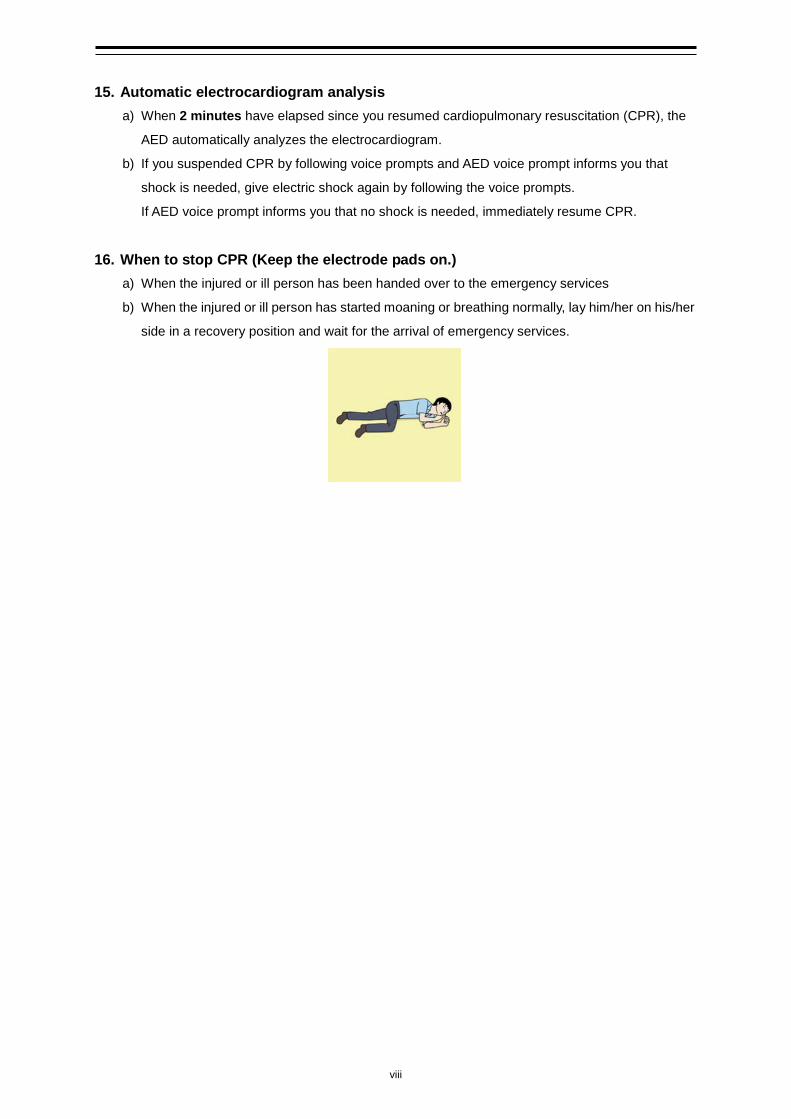
16. When to stop CPR (Keep the electrode pads on.)
a) When the injured or ill person has been handed over to the emergency services
b) When the injured or ill person has started moaning or breathing normally, lay him/her on his/her
side in a recovery position and wait for the arrival of emergency services.
ix
Contents
Safety Cautions ......................................................................................................... i Emergency Measures ............................................................................................... ii Contents ................................................................................................................... ix Preface..................................................................................................................... xv
Pictorial Indication .............................................................................................................................. xvi
Usage Precautions ........................................................................................................................... xvii
JLN-740A Overview of standard components ................................................... xxiii JLN-740N Overview of standard components ................................................... xxiv JLN-741A Overview of standard components .................................................... xxv JLN-741N Overview of standard components ................................................... xxvi Abbreviations .......................................................................................................xxvii Glossary ............................................................................................................... xxix How to use this manual ........................................................................................ xxx Chapter 1 General .................................................................................................................... 1-1
1.1 Functions ........................................................................................................................ 1-1 1.2 Features .......................................................................................................................... 1-2 1.3 Components .................................................................................................................... 1-4 1.4 Construction .................................................................................................................... 1-8 1.5 System Configuration ................................................................................................... 1-18
1.5.1 JLN-740A System Configuration Diagram............................................................... 1-18 1.5.2 JLN-740N System Configuration Diagram .............................................................. 1-19 1.5.3 JLN-741A System Configuration Diagram............................................................... 1-20 1.5.4 JLN-741N System Configuration Diagram .............................................................. 1-21
Chapter 2 Function of Each Components ................................................................................ 2-1 2.1 Main Display NWZ-510SDW (For JLN-740A/741A) ....................................................... 2-1 2.2 Main Display NWZ-4640 (For JLN-740N/741N) ............................................................. 2-2 2.3 Remote Display (Optional) NWZ-650SDR/840SDR ...................................................... 2-3 2.4 MID (Optional) NWZ-4610 .............................................................................................. 2-4 2.5 Distance Counter (Optional) NWW-7 ............................................................................. 2-5
Chapter 3 Operation Method (JLN-740A/741A) ...................................................................... 3-1 3.1 Basic Operation .............................................................................................................. 3-2
3.1.1 Power Supply ON/OFF .............................................................................................. 3-2 3.1.2 Adjusting Brightness .................................................................................................. 3-4
3.2 Displaying Ship Speed/Accumulated Sailing Distance .................................................. 3-5 3.2.1 Displaying Ship Speeds ............................................................................................. 3-5 3.2.2 Displaying the Accumulated Sailing Distance ........................................................... 3-6
3.3 Displaying Alert ............................................................................................................... 3-8 Chapter 4 Setting by Using Menus (JLN-740A/741A) ............................................................. 4-1
x
4.1. Setting of NWZ-510SDW ................................................................................................ 4-2 4.1.1. Main Menu ................................................................................................................. 4-2 4.1.2. Common Operation of Each Menu ............................................................................ 4-4 4.1.3. Operation of Each Menu ............................................................................................ 4-5
4.1.3.1. Touch Position Calibration .................................................................................. 4-5 4.1.3.2. Brightness Adjustment ........................................................................................ 4-7 4.1.3.3. Date Setting ........................................................................................................ 4-8 4.1.3.4. Confirming the system information ................................................................... 4-10 4.1.3.5. Advanced Settings of the details of the equipment at installation of this
equipment ......................................................................................................... 4-11 4.1.3.6. Setting the number of decimal digits of a ship speed ...................................... 4-11 4.1.3.7. Ship Speed Unit Settings ................................................................................. 4-12 4.1.3.8. Setting the upper limit and the lower limit for ship speed alerts ...................... 4-13 4.1.3.9. SDME Advanced Settings ................................................................................ 4-15 4.1.3.10. Alert List ............................................................................................................ 4-15 4.1.3.11. Alert History ...................................................................................................... 4-16
4.2. Alert ............................................................................................................................... 4-17 4.2.1. JLN-740A Alert list ................................................................................................... 4-17 4.2.2. JLN-741A Alert list ................................................................................................... 4-19 4.2.3. Sentence list that generates “ID sentence abnormal(PARSING FAIL)” .................. 4-20
Chapter 5 Operation Method (JLN-740N/741N) ...................................................................... 5-1 5.1 Basic Operation .............................................................................................................. 5-2
5.1.1 Power Supply ON/OFF .............................................................................................. 5-2 5.1.2 Adjusting Brightness .................................................................................................. 5-4
5.2 Displaying Ship Speed/Accumulated Sailing Distance .................................................. 5-5 5.2.1 Displaying Ship Speeds ............................................................................................. 5-5 5.2.2 Displaying the Accumulated Sailing Distance ........................................................... 5-6
5.3 Displaying Alert ............................................................................................................... 5-7 Chapter 6 Setting by Using Menus (JLN-740N/741N) ............................................................. 6-1
6.1. Setting NWZ-4640 .......................................................................................................... 6-2 6.1.1. Calling a main menu .................................................................................................. 6-2 6.1.2. Common operations of menus screens ..................................................................... 6-4 6.1.3. Operation of each menu ............................................................................................ 6-5
6.1.3.1. Display setting .................................................................................................... 6-5 6.1.3.1.1. Adjusting contrast ........................................................................................ 6-5 6.1.3.1.2. Adjusting back light ...................................................................................... 6-6 6.1.3.1.3. Setting a click sound .................................................................................... 6-6 6.1.3.1.4. Setting a display screen ............................................................................... 6-7
6.1.3.1.4.1. STEP1 Selecting a display screen ..................................................... 6-8 6.1.3.1.4.2. STEP2 Selecting a screen structure .................................................. 6-9 6.1.3.1.4.3. STEP3 Selecting display contents ................................................... 6-11
6.1.3.1.5. Select a back light color ............................................................................. 6-14

xi
6.2. System setting .............................................................................................................. 6-15 6.3. Language setting .......................................................................................................... 6-15 6.4. Alert setting ................................................................................................................... 6-15 6.5. Sensor setting ............................................................................................................... 6-16 6.6. Date and time setting .................................................................................................... 6-16 6.7. Alert history display ....................................................................................................... 6-16 6.8. Alert list display ............................................................................................................. 6-17 6.9. Alert ............................................................................................................................... 6-17 6.9.1 Alerts that occur in JLN-741N ....................................................................................... 6-18 6.9.2 Alerts that occur in JLN-741N ....................................................................................... 6-19 6.9.3 Sentence list that generates “ID sentence abnormal(PARSING FAIL)” ............... 6-20 6.9.4 Display of alert list · history screen ............................................................................... 6-21 6.10. Installation setting ......................................................................................................... 6-22 6.10.1 System setting ....................................................................................................... 6-22 6.10.2 Language setting ................................................................................................... 6-23 6.10.3 Sensor setting ....................................................................................................... 6-23 6.10.4 Date setting ........................................................................................................... 6-23
Chapter 7 Operation Method (Option) ..................................................................................... 7-1 7.1 Basic Operation .............................................................................................................. 7-2
7.1.1 Adjusting Brightness .................................................................................................. 7-2 7.2 Displaying Ship Speed/Accumulated Sailing Distance .................................................. 7-4
7.2.1 Displaying Ship Speeds ............................................................................................. 7-4 7.2.2 Displaying the Accumulated Sailing Distance ........................................................... 7-5
7.3 Displaying Alert ............................................................................................................... 7-8 Chapter 8 Setting by Using Menus (Option) ............................................................................ 8-1
8.1. Setting of NWZ-650SDR/840SDR .................................................................................. 8-2 8.1.1. Main Menu ................................................................................................................. 8-2 8.1.2. Operation of Each Menu ............................................................................................ 8-4
8.1.2.1. Touch Position Calibration .................................................................................. 8-4 8.1.2.2. Brightness Adjustment ........................................................................................ 8-5 8.1.2.3. Date Setting ........................................................................................................ 8-6 8.1.2.4. Confirming the system information ..................................................................... 8-8 8.1.2.5. Advanced Settings of the details of the equipment at installation of this
equipment ........................................................................................................... 8-9 8.1.2.6. Display Mode Selection ...................................................................................... 8-9 8.1.2.7. Ship Speed Unit Settings ................................................................................. 8-10 8.1.2.8. SDME Advanced Settings ................................................................................ 8-11 8.1.2.9. SOG and STW selection .................................................................................. 8-12
8.2. Setting of NWZ-4610 .................................................................................................... 8-12 Chapter 9 Installation Method .................................................................................................. 9-1
9.1 Installation of the Main Display and Distribution Processor ........................................... 9-2 9.2 Installation of the Transducer Mounting ......................................................................... 9-3

xii
9.3 Connection Diagram ....................................................................................................... 9-4 9.3.1 JLN-740A inter-connection diagram .......................................................................... 9-4 9.3.2 JLN-740N inter-connection diagram .......................................................................... 9-5 9.3.3 JLN-741A inter-connection diagram .......................................................................... 9-6 9.3.4 JLN-741N inter-connection diagram .......................................................................... 9-7
Chapter 10 Maintenance and Inspection ................................................................................. 10-1 10.1 Routine Maintenance .................................................................................................... 10-1 10.2 Countermeasures for Abnormalities and Faults ........................................................... 10-2 10.3 Repair unit ..................................................................................................................... 10-2 10.4 Troubleshooting ............................................................................................................ 10-3
Chapter 11 After-Sales Service ................................................................................................ 11-1 11.1 Requesting Repair ........................................................................................................ 11-1 11.2 Recommendation of Inspection and Maintenance ....................................................... 11-2
Chapter 12 Disposal ................................................................................................................. 12-1 Chapter 13 Specification .......................................................................................................... 13-1
13.1. General Specification .................................................................................................... 13-1 13.1.1. JLN-740A ................................................................................................................. 13-1 13.1.2. JLN-740N ................................................................................................................. 13-1 13.1.3. JLN-741A ................................................................................................................. 13-2 13.1.4. JLN-741N ................................................................................................................. 13-2
13.2. JLN-740A/741A Main Display NWZ-510SDW .............................................................. 13-3 13.2.1. Display Unit .............................................................................................................. 13-3 13.2.2. Electrical Specifications ........................................................................................... 13-3 13.2.3. Environmental Requirements .................................................................................. 13-3 13.2.4. Mechanical Specifications ....................................................................................... 13-3 13.2.5. External Interface ..................................................................................................... 13-4
13.3. JLN-740N/741N Main Display NWZ-4640 .......................................................................... 13-5 13.3.1. Display Unit .............................................................................................................. 13-5 13.3.2. Electrical Specifications ........................................................................................... 13-5 13.3.3. Environmental Requirements .................................................................................. 13-5 13.3.4. Mechanical Specifications ....................................................................................... 13-5 13.3.5. External interface ..................................................................................................... 13-5
13.4. Distribution Processor NQA-7040 ................................................................................ 13-6 13.4.1. Electrical Specifications ........................................................................................... 13-6 13.4.2. Environmental Requirements .................................................................................. 13-6 13.4.3. Mechanical Specifications ....................................................................................... 13-6 13.4.4. External Interface ..................................................................................................... 13-6
13.5. Signal Processor NJC-70S ........................................................................................... 13-7 13.5.1. Electrical Specifications ........................................................................................... 13-7 13.5.2. Environmental Requirements .................................................................................. 13-7 13.5.3. Mechanical Specifications ....................................................................................... 13-7
13.6. Transducer mounting NKF-547 .................................................................................... 13-8
xiii
13.6.1. Electrical Specifications ........................................................................................... 13-8 13.6.2. Environmental Requirements .................................................................................. 13-8 13.6.3. Mechanical Specifications ....................................................................................... 13-8
13.7. Transducer mounting (Option) NKF-531E .................................................................... 13-9 13.7.1. Electrical Specifications ........................................................................................... 13-9 13.7.2. Environmental Requirements .................................................................................. 13-9 13.7.3. Mechanical Specifications ....................................................................................... 13-9
13.8. Remote Display (Optional) NWZ-650SDR ................................................................. 13-10 13.8.1. Display Unit ............................................................................................................ 13-10 13.8.2. Electrical Specifications ......................................................................................... 13-10 13.8.3. Environmental Requirements ................................................................................ 13-10 13.8.4. Mechanical Specifications ..................................................................................... 13-10
13.9. Remote Display (Optional) NWZ-840SDR ................................................................. 13-11 13.9.1. Display Unit ............................................................................................................ 13-11 13.9.2. Electrical Specifications ......................................................................................... 13-11 13.9.3. Environmental Requirements ................................................................................ 13-11 13.9.4. Mechanical Specifications ..................................................................................... 13-11
13.10. MID (Optional) NWZ-4610 .................................................................................. 13-12 13.10.1. Display Unit .................................................................................................... 13-12 13.10.2. Electrical Specifications .................................................................................. 13-12 13.10.3. Environmental Requirements ......................................................................... 13-12 13.10.4. Mechanical Specifications .............................................................................. 13-12
13.11. JLN-740A/N Data Format .................................................................................... 13-13 13.11.1. IEC 61162-1 Input/Output Data ...................................................................... 13-13
13.11.1.1. Output data ..................................................................................................... 13-13 13.11.1.2. Input data ........................................................................................................ 13-16
13.11.2. IEC 61162-450 I/F .......................................................................................... 13-19 13.12. JLN-741A/N Data Format .................................................................................... 13-20
13.12.1. IEC 61162-1 Output Data ............................................................................... 13-20 13.12.1.1. Output data ................................................................................................. 13-20
13.13. About Chinese version RoHS ............................................................................. 13-22 Appendix A Menu list .................................................................................................................. A-1
A.1 Display menu list (NWZ-510SDW, NWZ-650SDR/NWZ-840SDR) ................................. A-1 A.2 Display menu list (NWZ-4640)......................................................................................... A-6 A.3 Maintenance software menu list .................................................................................... A-10
Appendix B Installation Drawings ............................................................................................... B-1 Appendix C Error due to the deviation from the irradiation angle reference value .................... C-1
C.1 Errors by hull motions ........................................................................................................ C-1 Appendix D Spare Parts List ....................................................................................................... D-1

xiv
(This page intentionally left blank)
xv
Preface
Thank you for purchasing the Japan Radio Co., Ltd. JLN-740A/740N/741A/741N Doppler Log. This equipment is an SDME (Speed and Distance Measuring Equipment), complying with the regulations of IMO (International Marine Organization), measures and displays wide-range ship speed through the water.
• Please read all safety precautions, pictorial indication and manual carefully before using your equipment to ensure safe and proper use.
• Please keep this instruction manual handy for future reference. Doing so will allow you to understand and to be prepared for any contingency.
xvi
Pictorial Indication
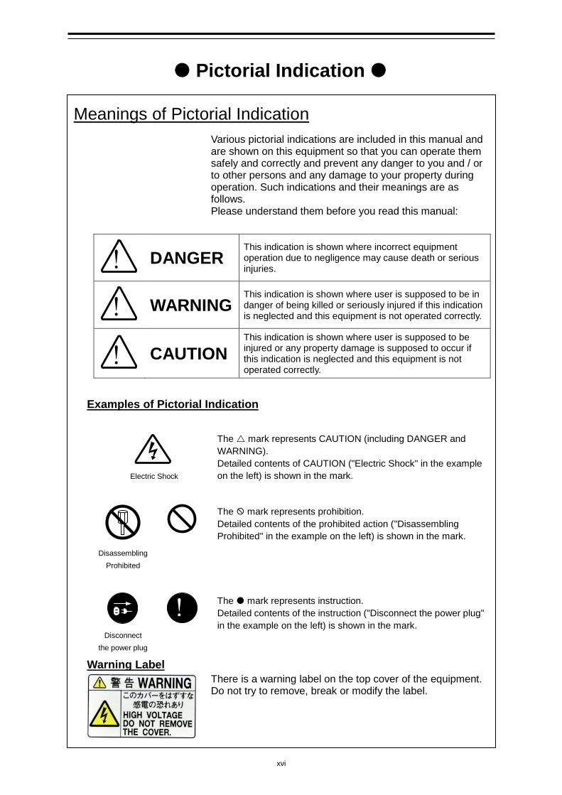
Meanings of Pictorial Indication Various pictorial indications are included in this manual and are shown on this equipment so that you can operate them safely and correctly and prevent any danger to you and / or to other persons and any damage to your property during operation. Such indications and their meanings are as follows. Please understand them before you read this manual:
!
DANGER This indication is shown where incorrect equipment operation due to negligence may cause death or serious injuries.
!
WARNING This indication is shown where user is supposed to be in danger of being killed or seriously injured if this indication is neglected and this equipment is not operated correctly.
!
CAUTION This indication is shown where user is supposed to be injured or any property damage is supposed to occur if this indication is neglected and this equipment is not operated correctly.
Examples of Pictorial Indication
Electric Shock
The mark represents CAUTION (including DANGER and WARNING). Detailed contents of CAUTION ("Electric Shock" in the example on the left) is shown in the mark.
Disassembling
Prohibited
The mark represents prohibition. Detailed contents of the prohibited action ("Disassembling Prohibited" in the example on the left) is shown in the mark.
Disconnect
the power plug
!
The mark represents instruction. Detailed contents of the instruction ("Disconnect the power plug" in the example on the left) is shown in the mark.
Warning Label There is a warning label on the top cover of the equipment. Do not try to remove, break or modify the label.

xvii
Usage Precautions
DANGER
Never remove the cover of this equipment. Touching the high-voltage section inside may cause an electric shock.
Before conducting inspection, maintenance or parts replacement, make sure to turn off the power and breaker. Failure to comply may cause an electric shock, fire or an equipment fault. Make sure to turn the breaker off since voltage is still outputted from the distribution processor even after the displays are turned off. Failure may result in equipment failure, or death or serious injury due to electric shock.
Do not touch the equipment with hands or gloves wet with water. Otherwise, an electric shock or a malfunction may occur.
xviii
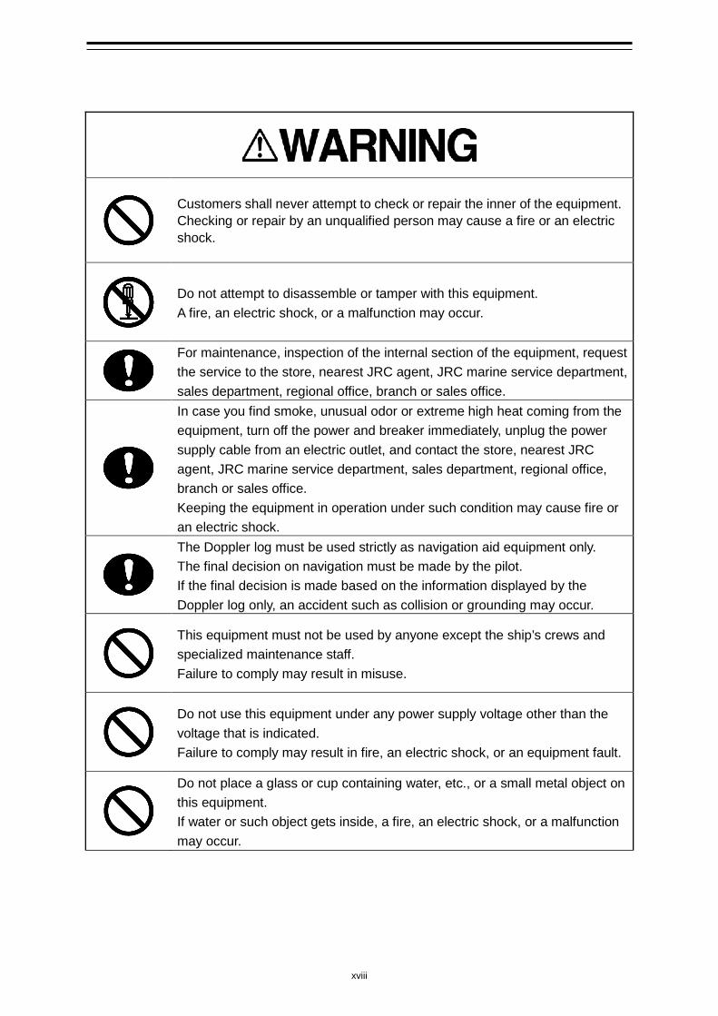
Customers shall never attempt to check or repair the inner of the equipment. Checking or repair by an unqualified person may cause a fire or an electric shock.
Do not attempt to disassemble or tamper with this equipment. A fire, an electric shock, or a malfunction may occur.
For maintenance, inspection of the internal section of the equipment, request the service to the store, nearest JRC agent, JRC marine service department, sales department, regional office, branch or sales office.
In case you find smoke, unusual odor or extreme high heat coming from the equipment, turn off the power and breaker immediately, unplug the power supply cable from an electric outlet, and contact the store, nearest JRC agent, JRC marine service department, sales department, regional office, branch or sales office. Keeping the equipment in operation under such condition may cause fire or an electric shock.
The Doppler log must be used strictly as navigation aid equipment only. The final decision on navigation must be made by the pilot. If the final decision is made based on the information displayed by the Doppler log only, an accident such as collision or grounding may occur.
This equipment must not be used by anyone except the ship’s crews and specialized maintenance staff. Failure to comply may result in misuse.
Do not use this equipment under any power supply voltage other than the voltage that is indicated. Failure to comply may result in fire, an electric shock, or an equipment fault.
Do not place a glass or cup containing water, etc., or a small metal object on this equipment. If water or such object gets inside, a fire, an electric shock, or a malfunction may occur.
xix
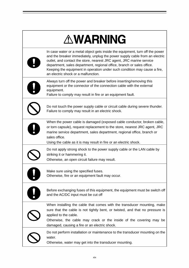
In case water or a metal object gets inside the equipment, turn off the power and the breaker immediately, unplug the power supply cable from an electric outlet, and contact the store, nearest JRC agent, JRC marine service department, sales department, regional office, branch or sales office. Keeping the equipment in operation under such condition may cause a fire, an electric shock or a malfunction.
Always turn off the power and breaker before inserting/removing this equipment or the connector of the connection cable with the external equipment. Failure to comply may result in fire or an equipment fault.
Do not touch the power supply cable or circuit cable during severe thunder. Failure to comply may result in an electric shock.
When the power cable is damaged (exposed cable conductor, broken cable, or torn capsule), request replacement to the store, nearest JRC agent, JRC marine service department, sales department, regional office, branch or sales office. Using the cable as it is may result in fire or an electric shock.
Do not apply strong shock to the power supply cable or the LAN cable by striking it or hammering it. Otherwise, an open circuit failure may result.
Make sure using the specified fuses. Otherwise, fire or an equipment fault may occur.
Before exchanging fuses of this equipment, the equipment must be switch off and the AC/DC input must be cut off
When installing the cable that comes with the transducer mounting, make sure that the cable is not tightly bent, or twisted, and that no pressure is applied to the cable. Otherwise, the cable may crack or the inside of the covering may be damaged, causing a fire or an electric shock.
Do not perform installation or maintenance to the transducer mounting on the water. Otherwise, water may get into the transducer mounting.
xx
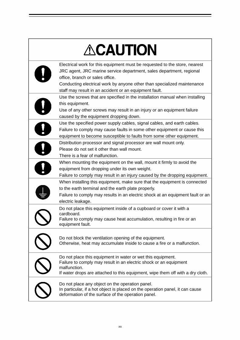
Electrical work for this equipment must be requested to the store, nearest JRC agent, JRC marine service department, sales department, regional office, branch or sales office. Conducting electrical work by anyone other than specialized maintenance staff may result in an accident or an equipment fault.
Use the screws that are specified in the installation manual when installing this equipment. Use of any other screws may result in an injury or an equipment failure caused by the equipment dropping down.
Use the specified power supply cables, signal cables, and earth cables. Failure to comply may cause faults in some other equipment or cause this equipment to become susceptible to faults from some other equipment.
Distribution processor and signal processor are wall mount only. Please do not set it other than wall mount. There is a fear of malfunction.
When mounting the equipment on the wall, mount it firmly to avoid the equipment from dropping under its own weight. Failure to comply may result in an injury caused by the dropping equipment.
When installing this equipment, make sure that the equipment is connected to the earth terminal and the earth plate properly. Failure to comply may results in an electric shock at an equipment fault or an electric leakage.
Do not place this equipment inside of a cupboard or cover it with a cardboard. Failure to comply may cause heat accumulation, resulting in fire or an equipment fault.
Do not block the ventilation opening of the equipment. Otherwise, heat may accumulate inside to cause a fire or a malfunction.
Do not place this equipment in water or wet this equipment. Failure to comply may result in an electric shock or an equipment malfunction. If water drops are attached to this equipment, wipe them off with a dry cloth.
Do not place any object on the operation panel. In particular, if a hot object is placed on the operation panel, it can cause deformation of the surface of the operation panel.
xxi
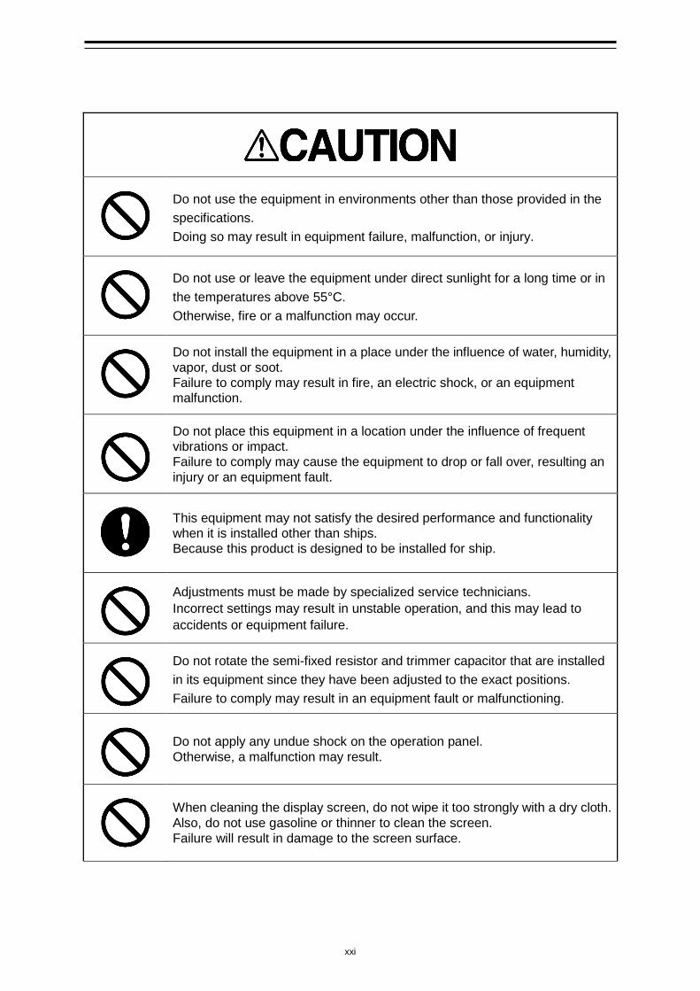
Do not use the equipment in environments other than those provided in the specifications. Doing so may result in equipment failure, malfunction, or injury.
Do not use or leave the equipment under direct sunlight for a long time or in the temperatures above 55°C. Otherwise, fire or a malfunction may occur.
Do not install the equipment in a place under the influence of water, humidity, vapor, dust or soot. Failure to comply may result in fire, an electric shock, or an equipment malfunction.
Do not place this equipment in a location under the influence of frequent vibrations or impact. Failure to comply may cause the equipment to drop or fall over, resulting an injury or an equipment fault.
This equipment may not satisfy the desired performance and functionality when it is installed other than ships. Because this product is designed to be installed for ship.
Adjustments must be made by specialized service technicians. Incorrect settings may result in unstable operation, and this may lead to accidents or equipment failure.
Do not rotate the semi-fixed resistor and trimmer capacitor that are installed in its equipment since they have been adjusted to the exact positions. Failure to comply may result in an equipment fault or malfunctioning.
Do not apply any undue shock on the operation panel. Otherwise, a malfunction may result.
When cleaning the display screen, do not wipe it too strongly with a dry cloth. Also, do not use gasoline or thinner to clean the screen. Failure will result in damage to the screen surface.
xxii
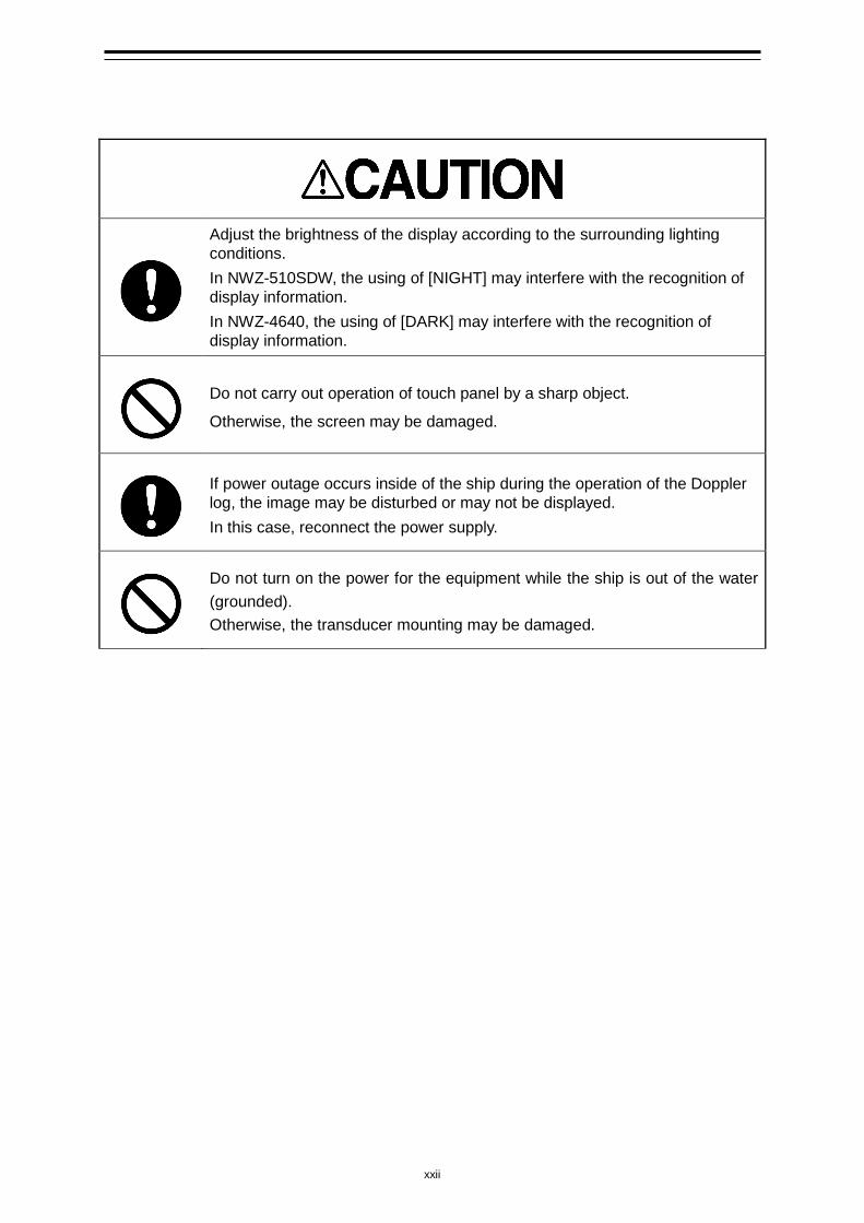
Adjust the brightness of the display according to the surrounding lighting conditions. In NWZ-510SDW, the using of [NIGHT] may interfere with the recognition of display information. In NWZ-4640, the using of [DARK] may interfere with the recognition of display information.
Do not carry out operation of touch panel by a sharp object.
Otherwise, the screen may be damaged.
If power outage occurs inside of the ship during the operation of the Doppler log, the image may be disturbed or may not be displayed. In this case, reconnect the power supply.
Do not turn on the power for the equipment while the ship is out of the water (grounded). Otherwise, the transducer mounting may be damaged.
xxiii
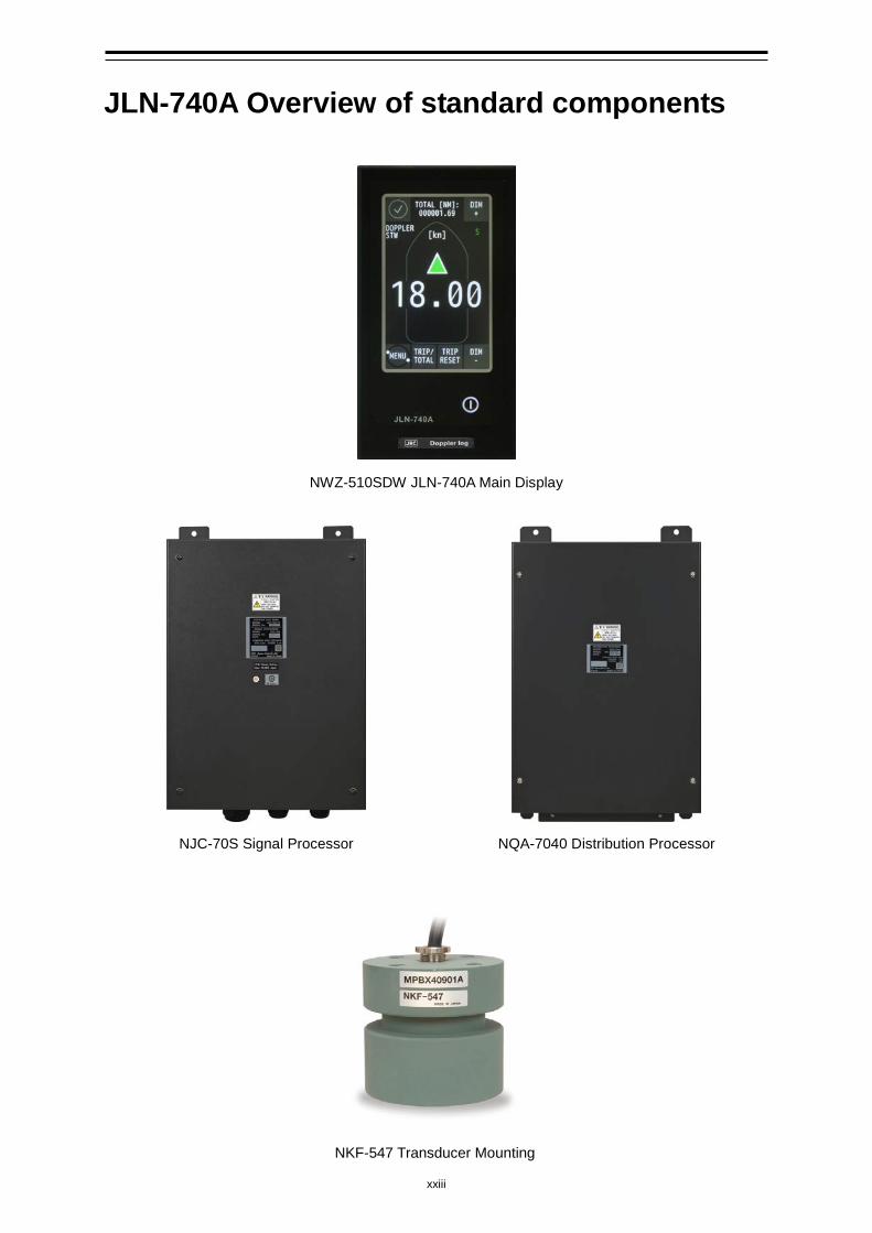
JLN-740A Overview of standard components
NWZ-510SDW JLN-740A Main Display
NJC-70S Signal Processor NQA-7040 Distribution Processor
NKF-547 Transducer Mounting
xxiv
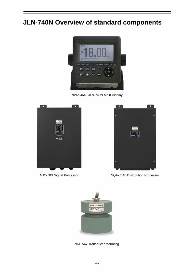
JLN-740N Overview of standard components
NWZ-4640 JLN-740N Main Display
NJC-70S Signal Processor NQA-7040 Distribution Processor
NKF-547 Transducer Mounting
xxv
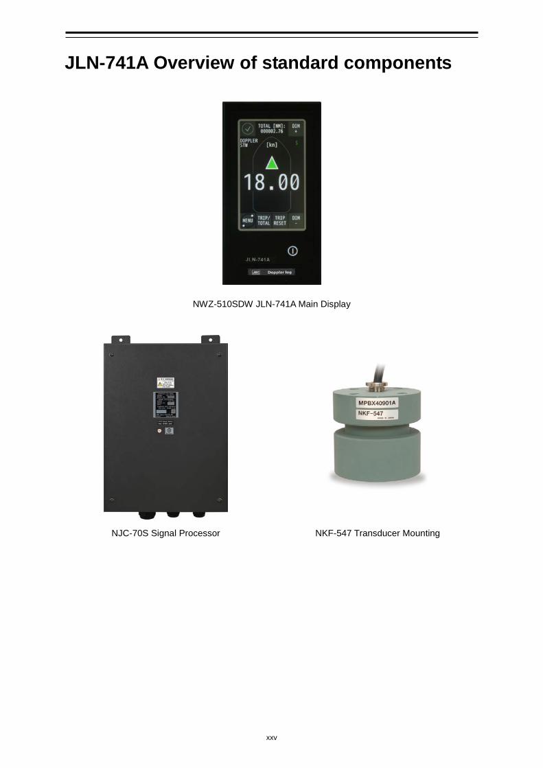
JLN-741A Overview of standard components
NWZ-510SDW JLN-741A Main Display
NJC-70S Signal Processor NKF-547 Transducer Mounting
xxvi
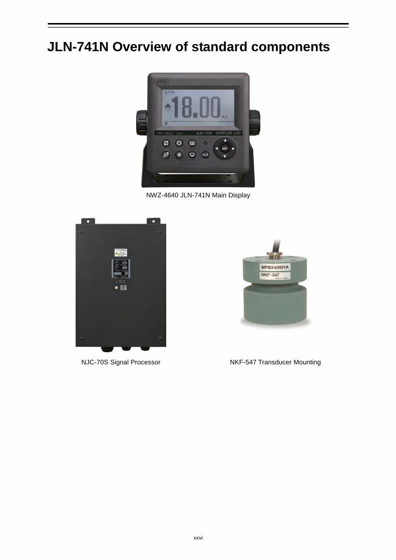
JLN-741N Overview of standard components
NWZ-4640 JLN-741N Main Display
NJC-70S Signal Processor NKF-547 Transducer Mounting
xxvii
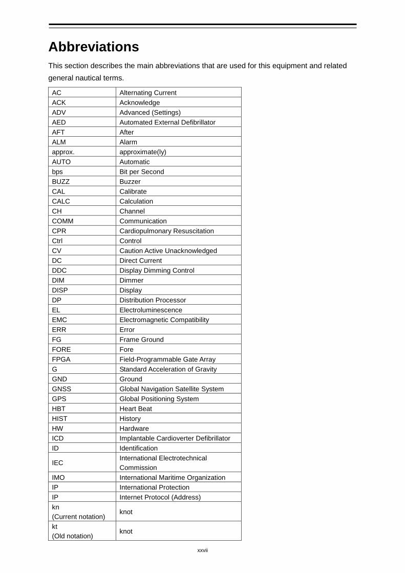
Abbreviations This section describes the main abbreviations that are used for this equipment and related general nautical terms. AC Alternating Current ACK Acknowledge ADV Advanced (Settings) AED Automated External Defibrillator AFT After ALM Alarm approx. approximate(ly) AUTO Automatic bps Bit per Second BUZZ Buzzer CAL Calibrate CALC Calculation CH Channel COMM Communication CPR Cardiopulmonary Resuscitation Ctrl Control CV Caution Active Unacknowledged DC Direct Current DDC Display Dimming Control DIM Dimmer DISP Display DP Distribution Processor EL Electroluminescence EMC Electromagnetic Compatibility ERR Error FG Frame Ground FORE Fore FPGA Field-Programmable Gate Array G Standard Acceleration of Gravity GND Ground GNSS Global Navigation Satellite System GPS Global Positioning System HBT Heart Beat HIST History HW Hardware ICD Implantable Cardioverter Defibrillator ID Identification
IEC International Electrotechnical Commission
IMO International Maritime Organization IP International Protection IP Internet Protocol (Address) kn (Current notation)
knot
kt (Old notation)
knot
xxviii
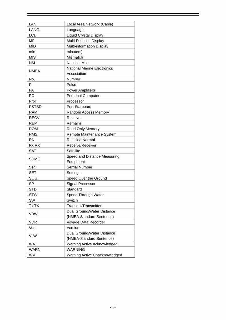
LAN Local Area Network (Cable) LANG. Language LCD Liquid Crystal Display MF Multi-Function Display MID Multi-information Display min minute(s) MIS Mismatch NM Nautical Mile
NMEA National Marine Electronics Association
No. Number P Pulse PA Power Amplifiers PC Personal Computer Proc Processor PSTBD Port-Starboard RAM Random Access Memory RECV Receive REM Remains ROM Read Only Memory RMS Remote Maintenance System RN Rectified Normal Rx RX Receive/Receiver SAT Satellite
SDME Speed and Distance Measuring Equipment
Ser. Serrial Number SET Settings SOG Speed Over the Ground SP Signal Processor STD Standard STW Speed Through Water SW Switch Tx TX Transmit/Transmitter
VBW Dual Ground/Water Distance (NMEA-Standard Sentence)
VDR Voyage Data Recorder Ver. Version
VLW Dual Ground/Water Distance (NMEA-Standard Sentence)
WA Warning Active Acknowledged WARN WARNING WV Warning Active Unacknowledged
xxix
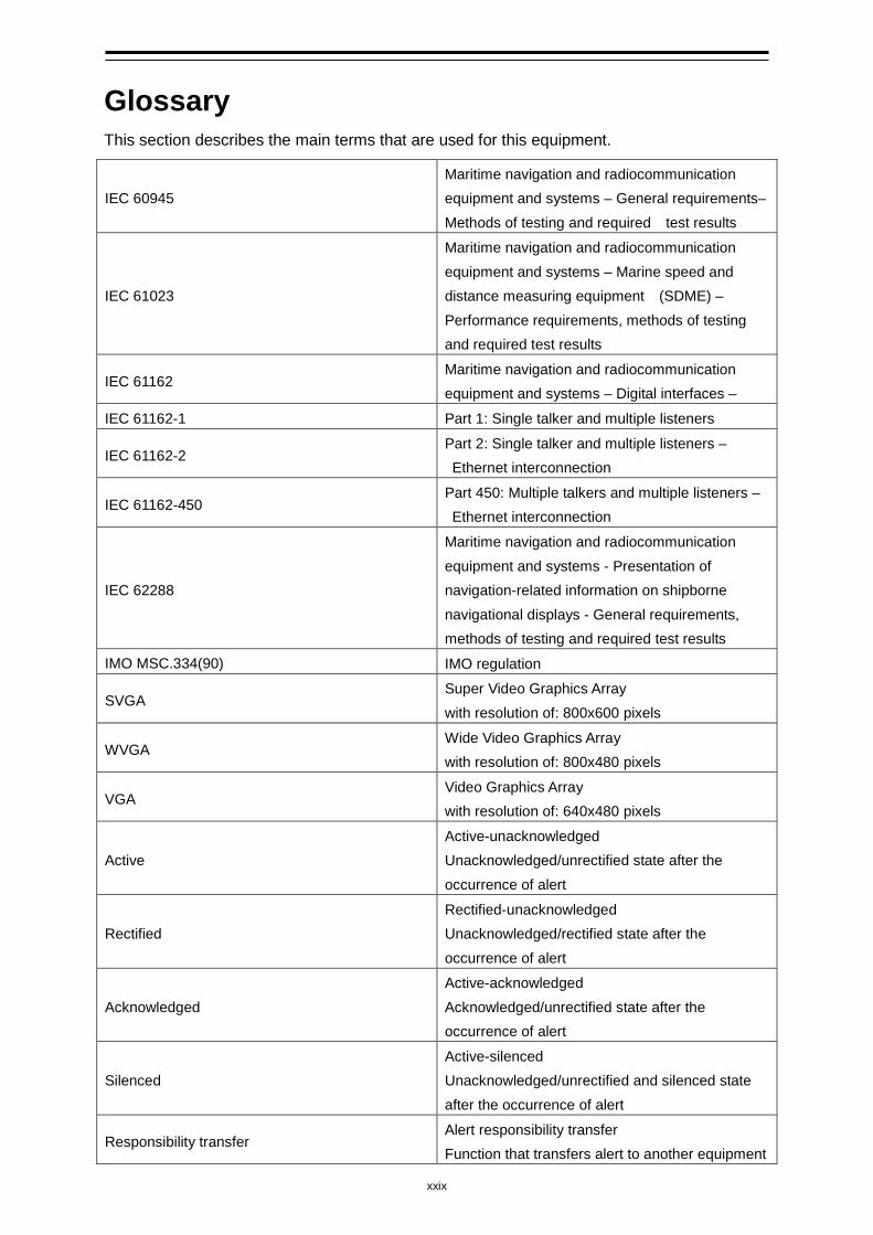
Glossary This section describes the main terms that are used for this equipment.
IEC 60945 Maritime navigation and radiocommunication equipment and systems – General requirements– Methods of testing and required test results
IEC 61023
Maritime navigation and radiocommunication equipment and systems – Marine speed and distance measuring equipment (SDME) – Performance requirements, methods of testing and required test results
IEC 61162 Maritime navigation and radiocommunication equipment and systems – Digital interfaces –
IEC 61162-1 Part 1: Single talker and multiple listeners
IEC 61162-2 Part 2: Single talker and multiple listeners – Ethernet interconnection
IEC 61162-450 Part 450: Multiple talkers and multiple listeners – Ethernet interconnection
IEC 62288
Maritime navigation and radiocommunication equipment and systems - Presentation of navigation-related information on shipborne navigational displays - General requirements, methods of testing and required test results
IMO MSC.334(90) IMO regulation
SVGA Super Video Graphics Array with resolution of: 800x600 pixels
WVGA Wide Video Graphics Array with resolution of: 800x480 pixels
VGA Video Graphics Array with resolution of: 640x480 pixels
Active Active-unacknowledged Unacknowledged/unrectified state after the occurrence of alert
Rectified Rectified-unacknowledged Unacknowledged/rectified state after the occurrence of alert
Acknowledged Active-acknowledged Acknowledged/unrectified state after the occurrence of alert
Silenced Active-silenced Unacknowledged/unrectified and silenced state after the occurrence of alert
Responsibility transfer Alert responsibility transfer Function that transfers alert to another equipment
xxx
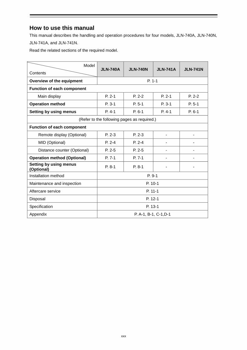
How to use this manual This manual describes the handling and operation procedures for four models, JLN-740A, JLN-740N,
JLN-741A, and JLN-741N.
Read the related sections of the required model.
Model
Contents JLN-740A JLN-740N JLN-741A JLN-741N
Overview of the equipment P. 1-1
Function of each component
Main display P. 2-1 P. 2-2 P. 2-1 P. 2-2
Operation method P. 3-1 P. 5-1 P. 3-1 P. 5-1
Setting by using menus P. 4-1 P. 6-1 P. 4-1 P. 6-1
(Refer to the following pages as required.)
Function of each component
Remote display (Optional) P. 2-3 P. 2-3 - -
MID (Optional) P. 2-4 P. 2-4 - -
Distance counter (Optional) P. 2-5 P. 2-5 - -
Operation method (Optional) P. 7-1 P. 7-1 - - Setting by using menus (Optional) P. 8-1 P. 8-1 - -
Installation method P. 9-1
Maintenance and inspection P. 10-1
Aftercare service P. 11-1
Disposal P. 12-1
Specification P. 13-1
Appendix P. A-1, B-1, C-1,D-1
1-1 Chapter 1 Outline of the Equipment
1
Chapter 1 General
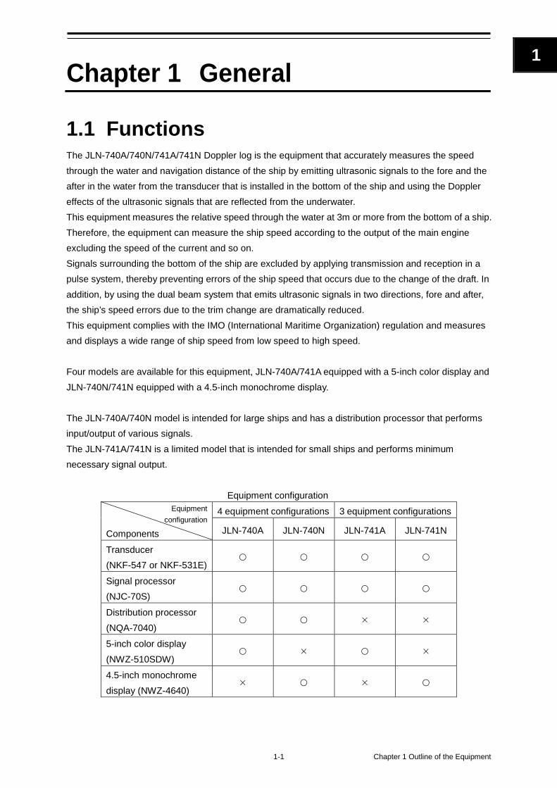
1.1 Functions The JLN-740A/740N/741A/741N Doppler log is the equipment that accurately measures the speed through the water and navigation distance of the ship by emitting ultrasonic signals to the fore and the after in the water from the transducer that is installed in the bottom of the ship and using the Doppler effects of the ultrasonic signals that are reflected from the underwater. This equipment measures the relative speed through the water at 3m or more from the bottom of a ship. Therefore, the equipment can measure the ship speed according to the output of the main engine excluding the speed of the current and so on. Signals surrounding the bottom of the ship are excluded by applying transmission and reception in a pulse system, thereby preventing errors of the ship speed that occurs due to the change of the draft. In addition, by using the dual beam system that emits ultrasonic signals in two directions, fore and after, the ship’s speed errors due to the trim change are dramatically reduced. This equipment complies with the IMO (International Maritime Organization) regulation and measures and displays a wide range of ship speed from low speed to high speed. Four models are available for this equipment, JLN-740A/741A equipped with a 5-inch color display and JLN-740N/741N equipped with a 4.5-inch monochrome display. The JLN-740A/740N model is intended for large ships and has a distribution processor that performs input/output of various signals. The JLN-741A/741N is a limited model that is intended for small ships and performs minimum necessary signal output.
Equipment configuration Equipment
configuration
Components
4 equipment configurations 3 equipment configurations
JLN-740A JLN-740N JLN-741A JLN-741N
Transducer (NKF-547 or NKF-531E)
Signal processor (NJC-70S)
Distribution processor (NQA-7040)
5-inch color display (NWZ-510SDW)
4.5-inch monochrome display (NWZ-4640)
Chapter 1 Outline of the Equipment 1-2
1.2 Features This equipment has the following features. Colour display unit with touch panel (JLN-740A/741A) This unit has the function of displaying a ship speed and a trip distance by using a 5-inch colour display as well as the user interface function for setting various parameters. Autonomic measurement function by an ultrasonic transducer mounting This function measures the fore/after speed of the ship by using ultrasonic signals. Therefore, the function can measure the ship speed relative to the sea water without any impact from the fair tide/tidal current near the bottom of the ship. This function applies a dual beam system that sends ultrasonic signals in two directions, ahead and astern, thereby dramatically reducing the ship speed measurement errors caused by the rolling of the hull of the ship. Digital/analog display switching function of a remote display (JLN-740A/740N) Both analog display and digital display are supported for the remote display NWZ-640SDR/840SDR, which is available as optional. Output sentence version switching function (JLN-740A/740N) This function outputs VBW (ship speed information) and VLW (trip distance) sentences. IEC61162-1 is applied to the sentences as the standard. In addition, the function supports NMEA Ver.1.5, Ver.2.1, Ver.2.3, and Ver.4.0. JLN-740A/740N supports multiple versions in the same way as the IEC61162-450 sentences of Ethernet output. The switching range is the same as that of serial output. Remote Maintenance function (Remote Maintenance System, RMS) (JLN-740A/740N) This function corresponds to the updating and equipment operation status checking of firmware by RMS. Maintainability and serviceability are improved by using the RMS function. To use this function, connection with VDR of JRC is necessary. Alert sequence function (JLN-740A/740N) This function transmits and receives alert information with Bridge Alert Management System (BAM) and Integrated Navigation System (INS). This function corresponds to alert management by BAM/INS. This function also supports Ethernet communication as well as contact and serial communication. The alert sequence function (excluding contact) complies with IMO Resolution A.1021 of IEC 61162 and IEC 61924.
1-3 Chapter 1 Outline of the Equipment
1
Ship speed alert function (JLN-740A/740N) This function enables the setting of an upper limit and a lower limit for the ahead/astern ship speeds by using any value. Since an alert is issued if the ship speed exceeds any of the set values, the values can be used as the guidelines for maintaining a constant speed. Transducer mounting damage prevention function (*under the process of patent acquistion) This equipment prevents damage of the oscillator due to the excessive output by controlling the transmission output according to the individual differences of the oscillators within the transducer. Transducer mounting checking function This function can check the waveforms that are received through the transducer mounting from the bridge and the operating status of the transducer mounting by connecting a maintenance PC. This eliminates the necessity for the shifting to the boatswain’s store/bottom compartment and its ventilation, thereby reducing the time required for maintenance/service. Bubble detection function (*under the process of patent acquisition) Bubbles near the transducer mounting radiation face can be detected by sending bubble detection ultrasonic signals at a constant interval. This function facilitates the detection of the cause of the missing values, which is difficult in the existing equipment. AC power failure detection function (JLN-740A/740N) This function outputs an alert and inputs ACK at a dedicated contact input/output when the AC power voltage drops. To operate the detection circuit, connection of DC24V is necessary. Dimmer function (JLN-740A/740N/741N) A dimmer function of the display unit by an external volume is supported. Individual control/bulk control can be selected by using the display dimmer. Applicable standards This equipment complies with the following standards. IMO MSC.334(90) IEC61023 ed.3 IEC60945 ed.4 IEC61162-1 ed.4 IEC61162-450 IEC62288 ed.2
Chapter 1 Outline of the Equipment 1-4
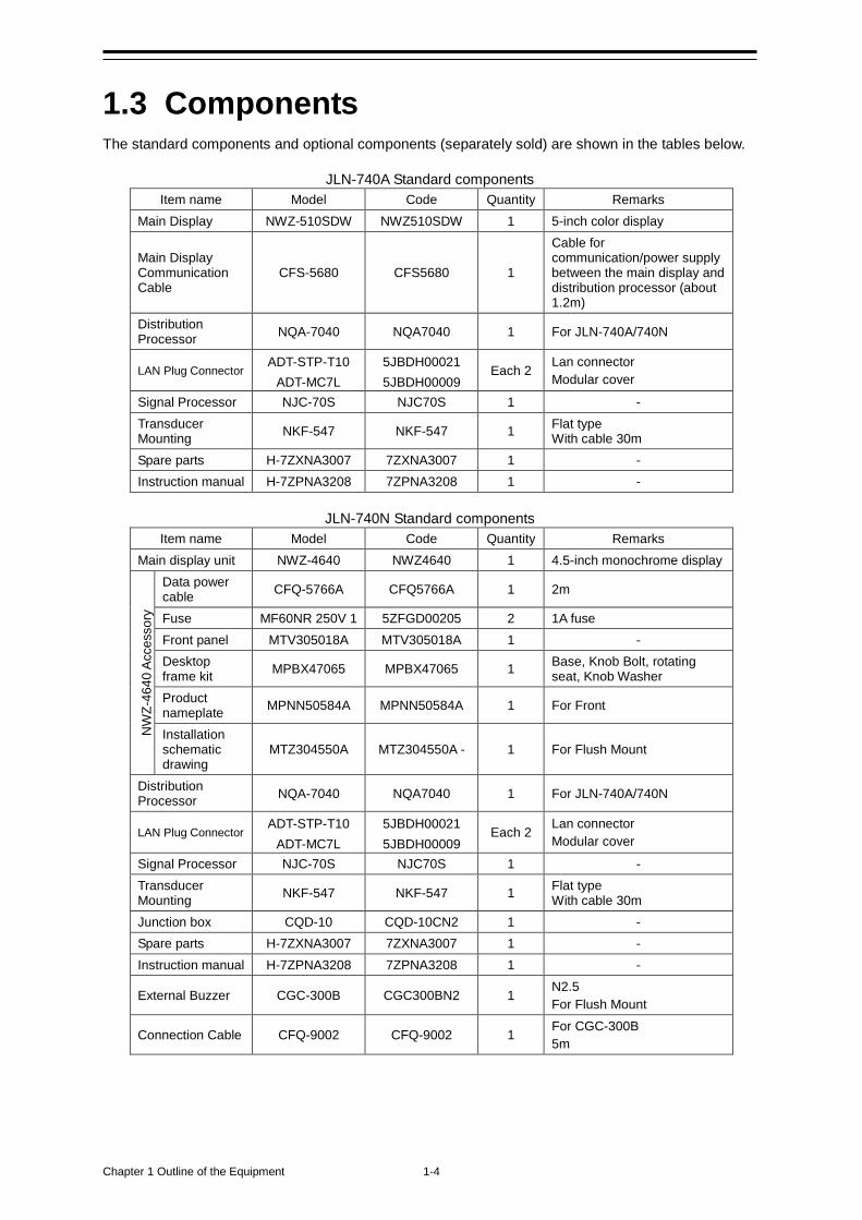
1.3 Components The standard components and optional components (separately sold) are shown in the tables below.
JLN-740A Standard components Item name Model Code Quantity Remarks
Main Display NWZ-510SDW NWZ510SDW 1 5-inch color display
Main Display Communication Cable
CFS-5680 CFS5680 1
Cable for communication/power supply between the main display and distribution processor (about 1.2m)
Distribution Processor NQA-7040 NQA7040 1 For JLN-740A/740N
LAN Plug Connector ADT-STP-T10
ADT-MC7L 5JBDH00021 5JBDH00009
Each 2 Lan connector Modular cover
Signal Processor NJC-70S NJC70S 1 - Transducer Mounting NKF-547 NKF-547 1 Flat type
With cable 30m Spare parts H-7ZXNA3007 7ZXNA3007 1 - Instruction manual H-7ZPNA3208 7ZPNA3208 1 -
JLN-740N Standard components
Item name Model Code Quantity Remarks Main display unit NWZ-4640 NWZ4640 1 4.5-inch monochrome display
NW
Z-46
40 A
cces
sory
Data power cable CFQ-5766A CFQ5766A 1 2m
Fuse MF60NR 250V 1 5ZFGD00205 2 1A fuse Front panel MTV305018A MTV305018A 1 - Desktop frame kit MPBX47065 MPBX47065 1 Base, Knob Bolt, rotating
seat, Knob Washer Product nameplate MPNN50584A MPNN50584A 1 For Front
Installation schematic drawing
MTZ304550A MTZ304550A - 1 For Flush Mount
Distribution Processor NQA-7040 NQA7040 1 For JLN-740A/740N
LAN Plug Connector ADT-STP-T10
ADT-MC7L 5JBDH00021 5JBDH00009
Each 2 Lan connector Modular cover
Signal Processor NJC-70S NJC70S 1 - Transducer Mounting NKF-547 NKF-547 1 Flat type
With cable 30m Junction box CQD-10 CQD-10CN2 1 - Spare parts H-7ZXNA3007 7ZXNA3007 1 - Instruction manual H-7ZPNA3208 7ZPNA3208 1 -
External Buzzer CGC-300B CGC300BN2 1 N2.5 For Flush Mount
Connection Cable CFQ-9002 CFQ-9002 1 For CGC-300B 5m
1-5 Chapter 1 Outline of the Equipment
1
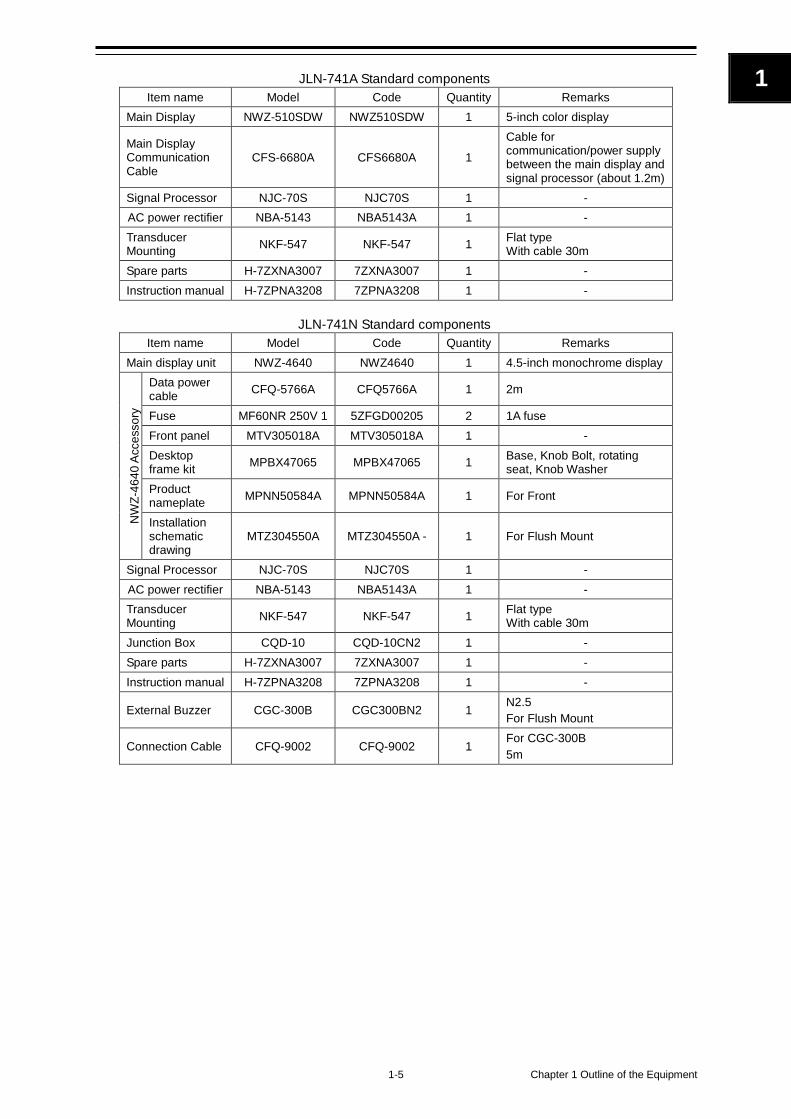
JLN-741A Standard components
Item name Model Code Quantity Remarks Main Display NWZ-510SDW NWZ510SDW 1 5-inch color display
Main Display Communication Cable
CFS-6680A CFS6680A 1
Cable for communication/power supply between the main display and signal processor (about 1.2m)
Signal Processor NJC-70S NJC70S 1 - AC power rectifier NBA-5143 NBA5143A 1 - Transducer Mounting NKF-547 NKF-547 1 Flat type
With cable 30m Spare parts H-7ZXNA3007 7ZXNA3007 1 - Instruction manual H-7ZPNA3208 7ZPNA3208 1 -
JLN-741N Standard components
Item name Model Code Quantity Remarks Main display unit NWZ-4640 NWZ4640 1 4.5-inch monochrome display
NW
Z-46
40 A
cces
sory
Data power cable CFQ-5766A CFQ5766A 1 2m
Fuse MF60NR 250V 1 5ZFGD00205 2 1A fuse Front panel MTV305018A MTV305018A 1 - Desktop frame kit MPBX47065 MPBX47065 1 Base, Knob Bolt, rotating
seat, Knob Washer Product nameplate MPNN50584A MPNN50584A 1 For Front
Installation schematic drawing
MTZ304550A MTZ304550A - 1 For Flush Mount
Signal Processor NJC-70S NJC70S 1 - AC power rectifier NBA-5143 NBA5143A 1 - Transducer Mounting NKF-547 NKF-547 1 Flat type
With cable 30m Junction Box CQD-10 CQD-10CN2 1 - Spare parts H-7ZXNA3007 7ZXNA3007 1 - Instruction manual H-7ZPNA3208 7ZPNA3208 1 -
External Buzzer CGC-300B CGC300BN2 1 N2.5 For Flush Mount
Connection Cable CFQ-9002 CFQ-9002 1 For CGC-300B 5m
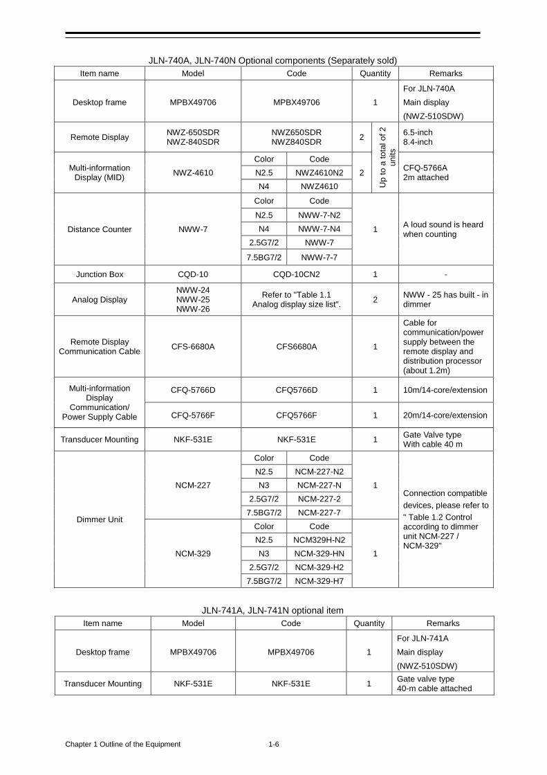
Chapter 1 Outline of the Equipment 1-6
JLN-740A, JLN-740N Optional components (Separately sold)
Item name Model Code Quantity Remarks
Desktop frame MPBX49706 MPBX49706 1 For JLN-740A Main display (NWZ-510SDW)
Remote Display NWZ-650SDR NWZ-840SDR
NWZ650SDR NWZ840SDR 2
Up
to a
tota
l of 2
un
its
6.5-inch 8.4-inch
Multi-information Display (MID) NWZ-4610
Color Code 2 CFQ-5766A
2m attached N2.5 NWZ4610N2 N4 NWZ4610
Distance Counter NWW-7
Color Code
1 A loud sound is heard when counting
N2.5 NWW-7-N2 N4 NWW-7-N4
2.5G7/2 NWW-7
7.5BG7/2 NWW-7-7
Junction Box CQD-10 CQD-10CN2 1 -
Analog Display NWW-24 NWW-25 NWW-26
Refer to "Table 1.1 Analog display size list". 2 NWW - 25 has built - in
dimmer
Remote Display Communication Cable CFS-6680A CFS6680A 1
Cable for communication/power supply between the remote display and distribution processor (about 1.2m)
Multi-information Display
Communication/ Power Supply Cable
CFQ-5766D CFQ5766D 1 10m/14-core/extension
CFQ-5766F CFQ5766F 1 20m/14-core/extension
Transducer Mounting NKF-531E NKF-531E 1 Gate Valve type With cable 40 m
Dimmer Unit
NCM-227
Color Code
1 Connection compatible devices, please refer to " Table 1.2 Control according to dimmer unit NCM-227 / NCM-329"
N2.5 NCM-227-N2 N3 NCM-227-N
2.5G7/2 NCM-227-2 7.5BG7/2 NCM-227-7
NCM-329
Color Code
1 N2.5 NCM329H-N2 N3 NCM-329-HN
2.5G7/2 NCM-329-H2 7.5BG7/2 NCM-329-H7
JLN-741A, JLN-741N optional item
Item name Model Code Quantity Remarks
Desktop frame MPBX49706 MPBX49706 1 For JLN-741A Main display (NWZ-510SDW)
Transducer Mounting NKF-531E NKF-531E 1 Gate valve type 40-m cable attached
1-7 Chapter 1 Outline of the Equipment
1
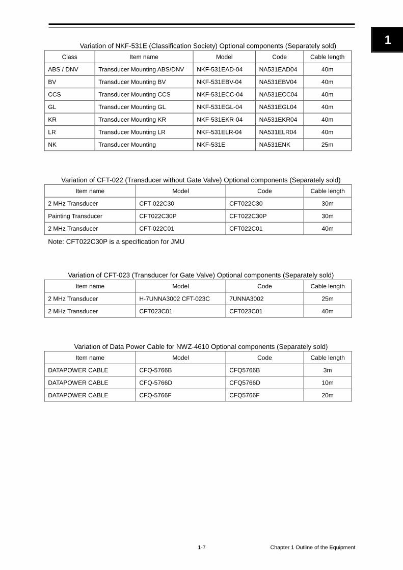
Variation of NKF-531E (Classification Society) Optional components (Separately sold)
Class Item name Model Code Cable length
ABS / DNV Transducer Mounting ABS/DNV NKF-531EAD-04 NA531EAD04 40m
BV Transducer Mounting BV NKF-531EBV-04 NA531EBV04 40m
CCS Transducer Mounting CCS NKF-531ECC-04 NA531ECC04 40m
GL Transducer Mounting GL NKF-531EGL-04 NA531EGL04 40m
KR Transducer Mounting KR NKF-531EKR-04 NA531EKR04 40m
LR Transducer Mounting LR NKF-531ELR-04 NA531ELR04 40m
NK Transducer Mounting NKF-531E NA531ENK 25m
Variation of CFT-022 (Transducer without Gate Valve) Optional components (Separately sold) Item name Model Code Cable length
2 MHz Transducer CFT-022C30 CFT022C30 30m
Painting Transducer CFT022C30P CFT022C30P 30m
2 MHz Transducer CFT-022C01 CFT022C01 40m
Note: CFT022C30P is a specification for JMU
Variation of CFT-023 (Transducer for Gate Valve) Optional components (Separately sold) Item name Model Code Cable length
2 MHz Transducer H-7UNNA3002 CFT-023C 7UNNA3002 25m
2 MHz Transducer CFT023C01 CFT023C01 40m
Variation of Data Power Cable for NWZ-4610 Optional components (Separately sold) Item name Model Code Cable length
DATAPOWER CABLE CFQ-5766B CFQ5766B 3m
DATAPOWER CABLE CFQ-5766D CFQ5766D 10m
DATAPOWER CABLE CFQ-5766F CFQ5766F 20m
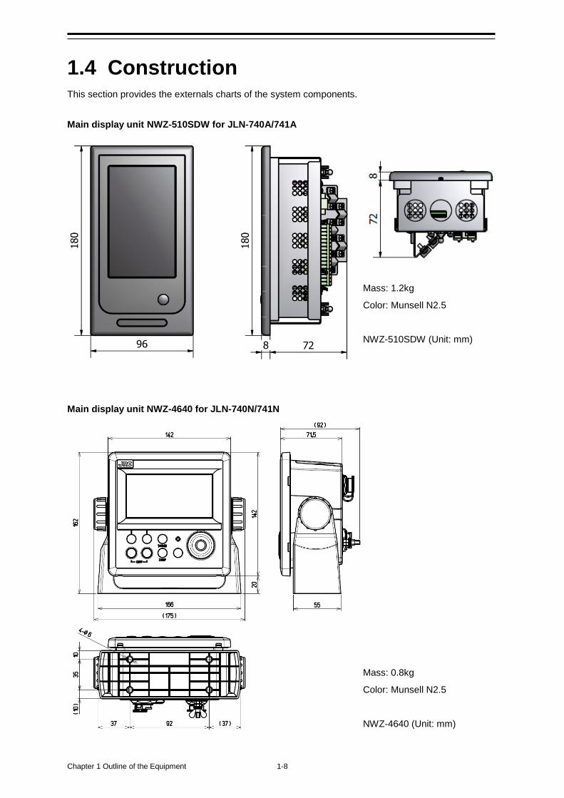
Chapter 1 Outline of the Equipment 1-8
1.4 Construction This section provides the externals charts of the system components. Main display unit NWZ-510SDW for JLN-740A/741A
Main display unit NWZ-4640 for JLN-740N/741N
Mass: 1.2kg
Color: Munsell N2.5
NWZ-510SDW (Unit: mm)
Mass: 0.8kg
Color: Munsell N2.5
NWZ-4640 (Unit: mm)
1-9 Chapter 1 Outline of the Equipment
1
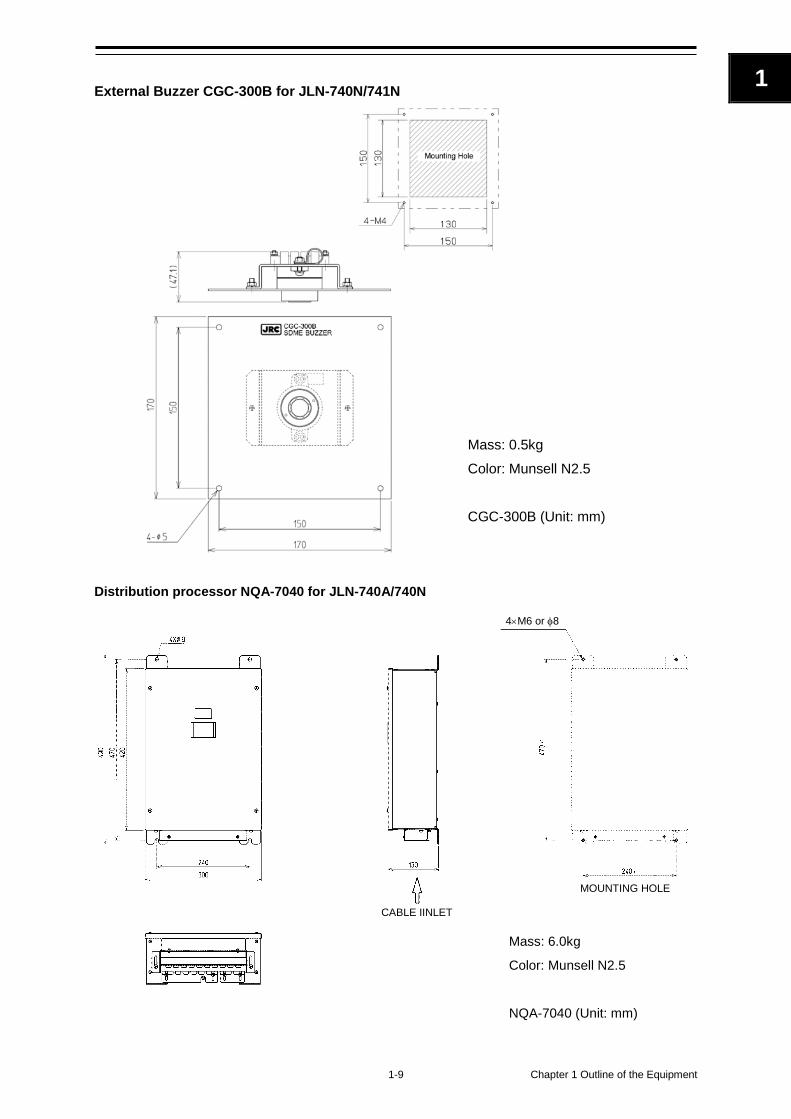
External Buzzer CGC-300B for JLN-740N/741N Distribution processor NQA-7040 for JLN-740A/740N
Mass: 6.0kg
Color: Munsell N2.5
NQA-7040 (Unit: mm)
4×M6 or φ8
CABLE IINLET
MOUNTING HOLE
Mass: 0.5kg Color: Munsell N2.5 CGC-300B (Unit: mm)
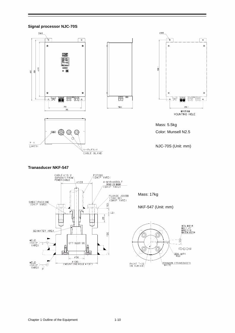
Chapter 1 Outline of the Equipment 1-10
Signal processor NJC-70S
Tranasducer NKF-547
Mass: 17kg NKF-547 (Unit: mm)
Mass: 5.5kg
Color: Munsell N2.5
NJC-70S (Unit: mm)
C

1-11 Chapter 1 Outline of the Equipment
1
Remote display NWZ-650SDR (optional)
Remote display NWZ-840SDR (optional)
Mass: 1.4kg
Color: Munsell N2.5
NWZ-650SDR (Unit: mm)
Mass: 2.1kg
Color: Munsell N2.5
NWZ-840SDR (Unit: mm)

Chapter 1 Outline of the Equipment 1-12
Desktop frame MPBX49706 (optional) Multi Information Display NWZ-4610 (optional)
Mass: 0.8kg
Color: Munsell N2.5
NWZ-4610 (Unit: mm)
Mass: 1.0kg
Color: Munsell N2.5
MPBX49706 (Unit: mm)
1-13 Chapter 1 Outline of the Equipment
1
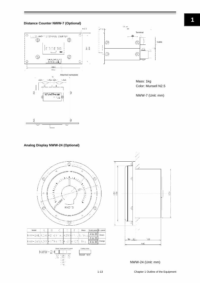
Distance Counter NWW-7 (Optional)
Mass: 1kg Color: Munsell N2.5 NWW-7 (Unit: mm)
Analog Display NWW-24 (Optional)
Attached nameplate
Cable
Terminal
-4 to 20
-5 to 25 -6 to 30
Munsell N2.5
Model Mass Scale panel E.L panel
Green
Orange
Model Coating colour Scale panel EL panel
NWW-24 (Unit: mm)
Chapter 1 Outline of the Equipment 1-14
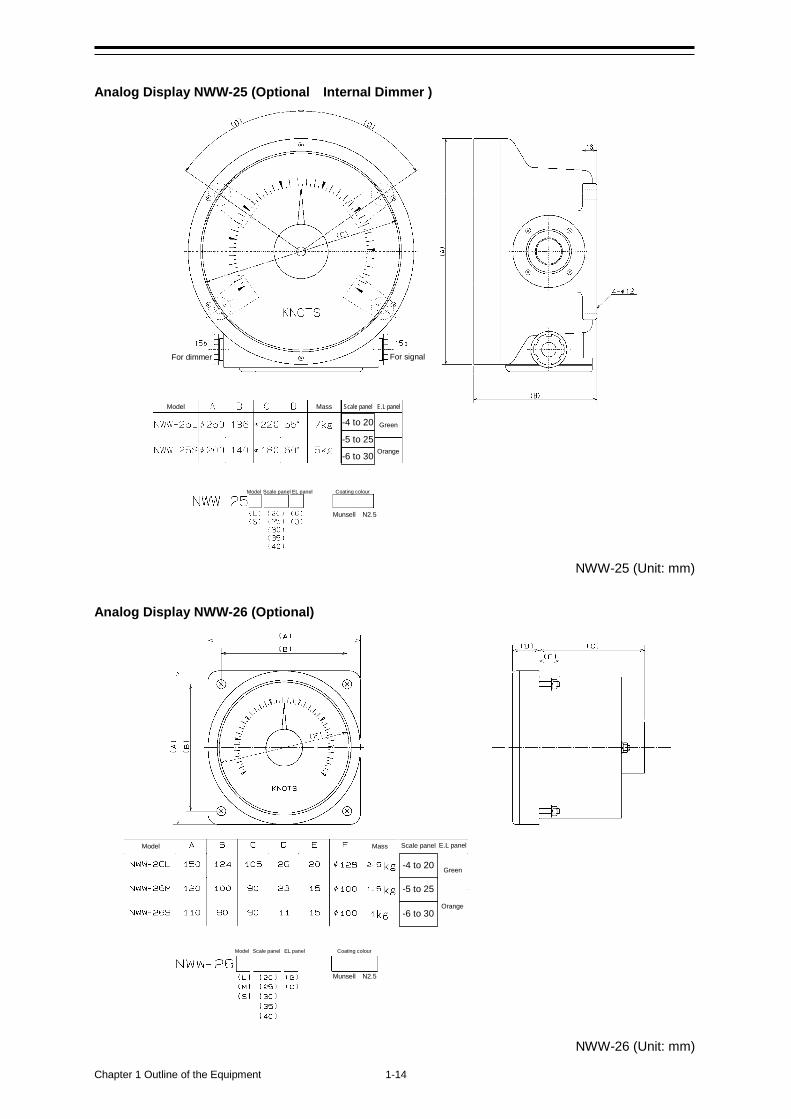
Analog Display NWW-25 (Optional Internal Dimmer )
NWW-25 (Unit: mm) Analog Display NWW-26 (Optional)
NWW-26 (Unit: mm)
-4 to 20
-5 to 25
-6 to 30
-4 to 20
-5 to 25
-6 to 30
For dimmer For signal
Munsell N2.5
Model Mass Scale panel E.L panel
Green
Orange
Model Coating colour Scale panel EL panel
Munsell N2.5
Model Mass Scale panel E.L panel
Green
Orange
Model Coating colour Scale panel EL panel

1-15 Chapter 1 Outline of the Equipment
1
Table 1.1 Analog display size list
NWW-24
(Flush mount type) NWW-25
(Wall mount type) NWW-26
(Panel flush mount type) Range Size Green EL Orange EL Green EL Orange EL Green EL Orange EL
-4∼2
0kn L NWW-24L20G NWW-24L20O NWW-25L20G NWW-25L20O NWW-26L20G NWW-26L20O
M - - - - NWW-26M20G NWW-26M20O S NWW-24S20G NWW-24S20O NWW-25S20G NWW-25S20O NWW-26S20G NWW-26S20O
-5∼2
5kn L NWW-24L25G NWW-24L25O NWW-25L25G NWW-25L25O NWW-26L25G NWW-26L25O
M - - - - NWW-26M25G NWW-26M25O S NWW-24S25G NWW-24S25O NWW-25S25G NWW-25S25O NWW-26S25G NWW-26S25O
-6∼3
0kn L NWW-24L30G NWW-24L30O NWW-25L30G NWW-25L30O NWW-26L30G NWW-26L30O
M - - - - NWW-26M30G NWW-26M30O S NWW-24S30G NWW-24S30O NWW-25S30G NWW-25S30O NWW-26S30G NWW-26S30O
Dimmer Unit NCM-227 (Optional)
Mass: 0.5kg Color: Munsell N2.5 NCM-227 (Unit: mm)
Terminal board
Chapter 1 Outline of the Equipment 1-16
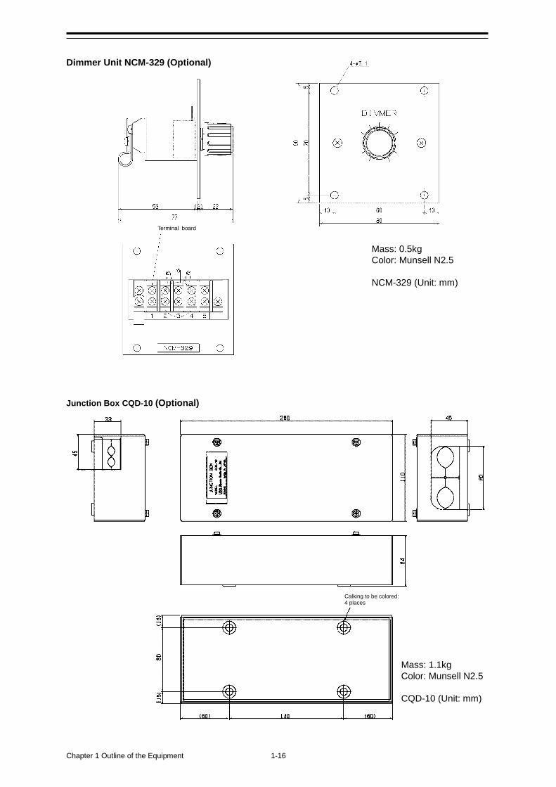
Dimmer Unit NCM-329 (Optional)
Junction Box CQD-10 (Optional)
Calking to be colored: 4 places
Mass: 0.5kg Color: Munsell N2.5 NCM-329 (Unit: mm)
Mass: 1.1kg Color: Munsell N2.5 CQD-10 (Unit: mm)
Terminal board
1-17 Chapter 1 Outline of the Equipment
1
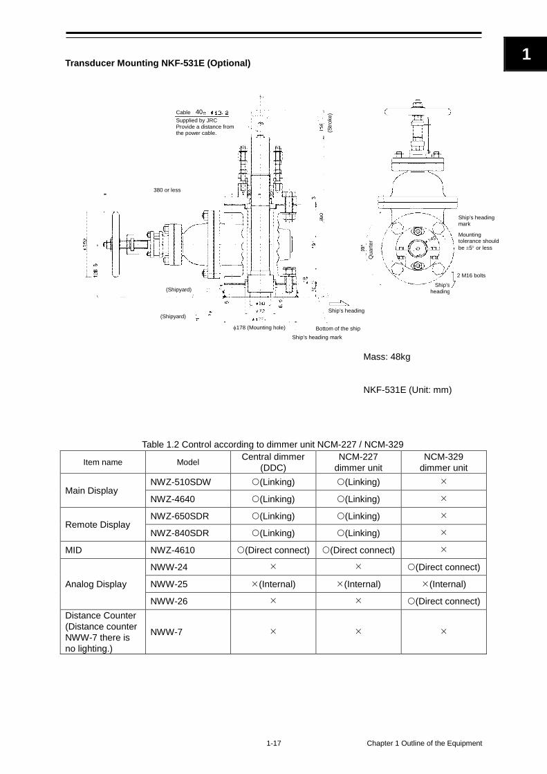
Transducer Mounting NKF-531E (Optional)
Table 1.2 Control according to dimmer unit NCM-227 / NCM-329
Item name Model Central dimmer (DDC)
NCM-227 dimmer unit
NCM-329 dimmer unit
Main Display NWZ-510SDW (Linking) (Linking)
NWZ-4640 (Linking) (Linking)
Remote Display NWZ-650SDR (Linking) (Linking)
NWZ-840SDR (Linking) (Linking)
MID NWZ-4610 (Direct connect) (Direct connect)
Analog Display
NWW-24 (Direct connect)
NWW-25 (Internal) (Internal) (Internal)
NWW-26 (Direct connect) Distance Counter (Distance counter NWW-7 there is no lighting.)
NWW-7
Mass: 48kg
NKF-531E (Unit: mm)
Cable Supplied by JRC
Provide a distance from the power cable.
380 or less
(Shipyard)
(Shipyard)
(Stro
ke)
φ178 (Mounting hole) Ship’s heading mark
Bottom of the ship
Ship’s heading
Ship’s heading mark
Ship’s heading
Qua
rter
Mounting tolerance should be ±5° or less
2 M16 bolts
40
Chapter 1 Outline of the Equipment 1-18
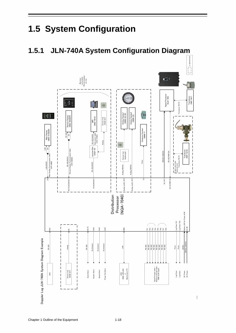
1.5 System Configuration
1.5.1 JLN-740A System Configuration Diagram
Dis
trib
ution
Pro
cess
or
(NQ
A-7040)
Rem
ote
Dis
pla
y(N
WZ-6
50S
DR
)
Ana
log
Dis
pla
y1(N
WW
-24/2
6)
Analo
g,100V
AC
Analo
g,100V
AC
RS-422,2
4V
DC
RS-422,2
4V
DC
LA
N
Dry
Conta
ct
Dry
Conta
ct
Dry
Conta
ct
Analo
g
Pow
er
Fai
l A
larm
Speed A
larm
Sys
tem
Ala
rm
Ana
log
Dis
pla
y2(N
WW
-25)
RS-422
Mai
n D
ispla
y(N
WZ-5
10S
DW
)
LA
N,2
4V
DC
Puls
eLog
Puls
e
DC
Pow
er
24V
DC
AC
Pow
er
100V
AC
/230V
AC
Dopple
r Log
JLN
-740A
Syst
em
Dia
gram
Exa
mple
VD
R(R
MS/JR
CLA
N)
or
Main
tenan
ce P
C
MID
(NW
Z-4
610
)
Serial
Ala
rm
Dim
mer
Unit
(NC
M-227)
Maxi
mum
connecta
ble
R
em
ote
dis
pla
ys
are
tw
o.
RX
RX,T
X
Log
Puls
e T
X1
ALM
ALM
ALM
AC
IN
Batt
ery
24V
for
Pow
er
ALM
RM
S
J10
RX,T
X,D
C24V
OU
T
TX
,DC
24V
OU
T
Analo
g o
ut,EL O
UT
Analo
g o
ut,EL O
UT
TX
Main
Dis
pla
y C
om
munic
atio
n C
able
(CFS
-5680)
LA
N
DC
Dim
mer
Unit
(NC
M-3
29)
RS-422
GP
SR
X2
Rem
ote
Dis
play
Com
munic
atio
n C
able
(CFS
-6680A
)
RS-422
DC
Sig
nal Pro
cess
or(N
JC
-70S)
AC
OU
T
RX,T
X,P
WR-EN
100V
AC
/230V
AC
RS-422,P
WR-EN
Tra
nsd
ucer
(NKF-5
47)
Tra
nsd
ucer
RX
,TX
Puls
eLog
Puls
e T
X2
Log
Puls
e
Dim
mer
Unit
(NC
M-227)
Analo
g
Jun
ctio
n B
ox(C
QD
-10)
RS-422,2
4V
DC
Data
pow
er
cable
(CFQ
-5766A
)
Tra
nsd
ucer
(NKF-5
31E
)
Tra
nsd
ucer
RX
,TX
If g
ate
val
ve t
ype
(optional item
)
is o
ptional
ite
m
RS-422
RS-422
RS-422
RS-422
RS-422
RS-422
RS-422
RS-422
TX
1
TX
2
TX
3
TX
4
TX
5
TX
6
TX
7
TX
8
Speed t
hro
ugh
wat
er
/
Dis
tance t
hro
ugh
wate
rV
BW
/V
LW
outp
ut
Dis
tanc
e C
oun
ter
(NW
W-7
)
Puls
e
20170822
1-19 Chapter 1 Outline of the Equipment
1
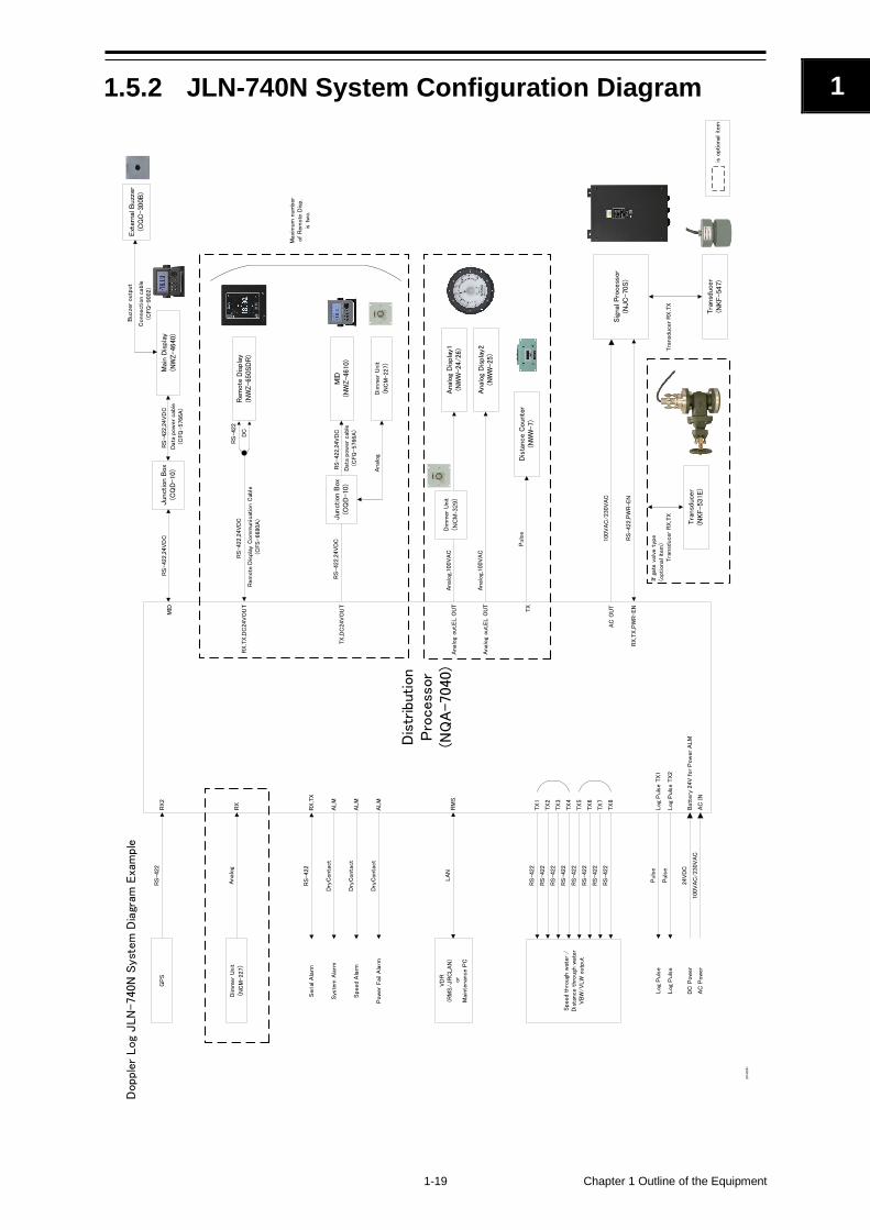
1.5.2 JLN-740N System Configuration Diagram
Dis
trib
ution
Pro
cess
or
(NQ
A-7040)
Ana
log
Dis
pla
y1(N
WW
-24/2
6)
Analo
g,100V
AC
Analo
g,100V
AC
LA
N
Analo
g
Ana
log
Dis
pla
y2(N
WW
-25)
Puls
eLog
Puls
e
DC
Pow
er
24V
DC
AC
Pow
er
100V
AC
/230V
AC
Dopple
r Log
JLN
-740N
Syst
em
Dia
gram
Exa
mple
Dim
mer
Unit
(NC
M-227)
RX
Log
Puls
e T
X1
AC
IN
Batt
ery
24V
for
Pow
er
ALM
RM
SA
nalo
g o
ut,EL O
UT
Analo
g o
ut,EL O
UT
Dim
mer
Unit
(NC
M-3
29)
RS-422
GP
SR
X2
AC
OU
T
RX,T
X,P
WR-EN
Mai
n D
ispla
y(N
WZ-4
640
)M
IDR
S-422,2
4V
DC
Data
pow
er
cable
(CFQ
-5766A
)
VD
R(R
MS/JR
CLA
N)
or
Main
tenan
ce P
C
Dry
Conta
ct
Dry
Conta
ct
Dry
Conta
ct
Pow
er
Fai
l A
larm
Speed A
larm
Sys
tem
Ala
rm
RS-422
Serial
Ala
rmR
X,T
X
ALM
ALM
ALM
Puls
eLog
Puls
eLog
Puls
e T
X2
Rem
ote
Dis
pla
y(N
WZ-6
50S
DR
)
RS-422,2
4V
DC
RS-422,2
4V
DC
MID
(NW
Z-4
610
)
Maxi
mum
num
ber
of
Rem
ote
Dis
p.
is t
wo.
RX,T
X,D
C24V
OU
T
TX
,DC
24V
OU
T
RS-422
DC
Dim
mer
Unit
(NC
M-227)
Analo
g
Jun
ctio
n B
ox(C
QD
-10)
RS-422,2
4V
DC
Data
pow
er
cable
(CFQ
-5766A
)
Jun
ctio
n B
ox(C
QD
-10)
RS-422,2
4V
DC
Sig
nal Pro
cess
or(N
JC
-70S)
100V
AC
/230V
AC
RS-422,P
WR-EN
Tra
nsd
ucer
(NKF-5
47)
Tra
nsd
ucer
RX
,TX
Tra
nsd
ucer
(NKF-5
31E
)
Tra
nsd
ucer
RX
,TX
If g
ate
val
ve t
ype
(optional item
)
is o
ptional
ite
m
TX
RS-422
RS-422
RS-422
RS-422
RS-422
RS-422
RS-422
RS-422
TX
1
TX
2
TX
3
TX
4
TX
5
TX
6
TX
7
TX
8
Speed t
hro
ugh
wat
er
/
Dis
tance t
hro
ugh
wate
rV
BW
/V
LW
outp
ut
Dis
tanc
e C
oun
ter
(NW
W-7
)
Puls
e
Rem
ote
Dis
play
Com
munic
atio
n C
able
(CFS
-6680A
)
20180201
Ext
erna
l Buzz
er(C
GC
-300B
)C
onnection c
able
(CFQ
-9002)
Buzze
r outp
ut
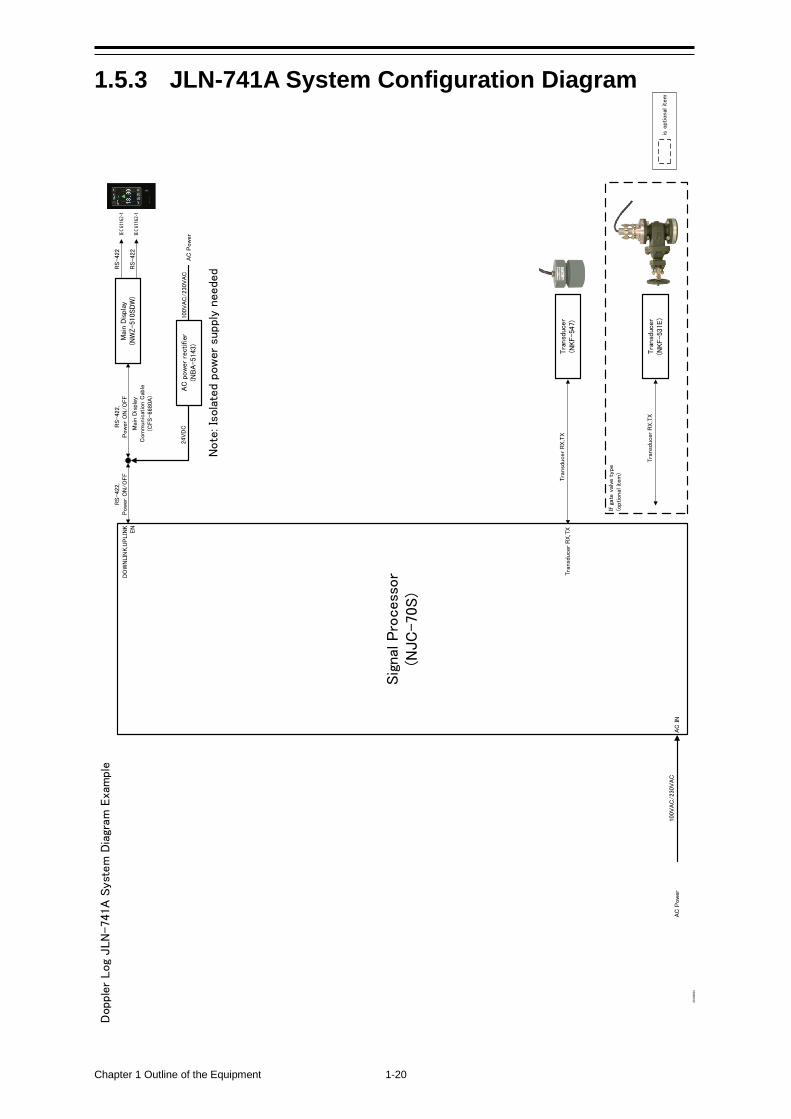
Chapter 1 Outline of the Equipment 1-20
1.5.3 JLN-741A System Configuration Diagram
Sig
nal
Pro
cess
or
(NJC
-70S)
Mai
n D
ispla
y(N
WZ-5
10S
DW
)
AC
Pow
er
100V
AC
/230V
AC
AC
Pow
er
100V
AC
/230V
AC
Dopple
r Log
JLN
-741A
Syst
em
Dia
gram
Exa
mple
AC
IN
Tra
nsd
ucer
RX
,TX
Tra
nsd
ucer
(NKF-5
47)
Tra
nsd
ucer
RX
,TX
DO
WN
LIN
K,U
PLIN
KEN
Main
Dis
pla
y C
om
munic
atio
n C
able
(CFS
-6680A
)
RS-422,
Pow
er
ON
/O
FF
RS-422,
Pow
er
ON
/O
FF
AC
pow
er r
ectifier
(NB
A-5
143
)
24V
DC
RS-422
RS-422
IEC6
1162
-1
IEC6
1162
-1
Tra
nsd
ucer
(NKF-5
31E
)
Tra
nsd
ucer
RX
,TX
If g
ate
val
ve t
ype
(optional item
)
is o
ptional
ite
m
20180201
Note
: Is
ola
ted p
ow
er
supply
needed
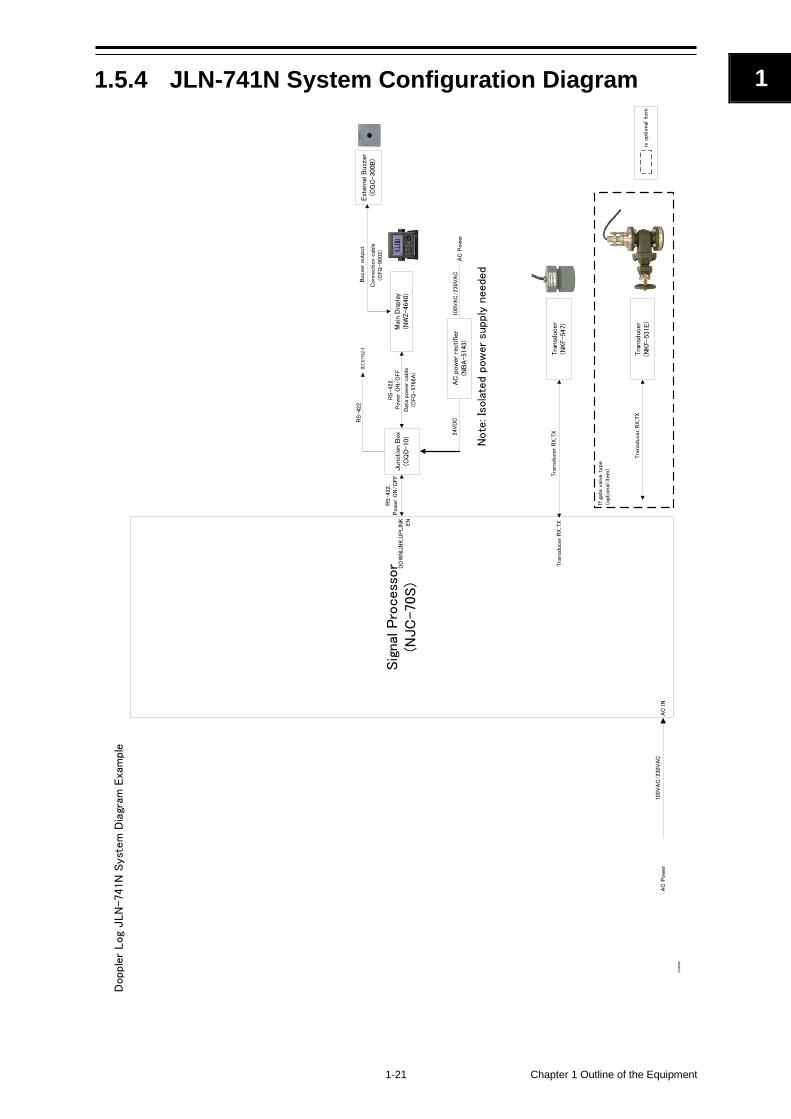
1-21 Chapter 1 Outline of the Equipment
1
1.5.4 JLN-741N System Configuration Diagram
Sig
nal
Pro
cess
or
(NJC
-70S)
AC
Pow
er
100V
AC
/230V
AC
Dopple
r Log
JLN
-741N
Syst
em
Dia
gram
Exa
mple
AC
IN
Mai
n D
ispla
y(N
WZ-4
640
)
RS-422,
Pow
er
ON
/O
FF
Data
pow
er
cable
(CFQ
-5766A
)
DO
WN
LIN
K,U
PLIN
KEN
Jun
ctio
n B
ox(C
QD
-10)
RS-422,
Pow
er
ON
/O
FF
RS-422
IEC6
1162
-1
AC
Pow
er
100V
AC
/230V
AC
AC
pow
er r
ectifier
(NB
A-5
143
)
24V
DC
Tra
nsd
ucer
RX
,TX
Tra
nsd
ucer
(NKF-5
47)
Tra
nsd
ucer
RX
,TX
Tra
nsd
ucer
(NKF-5
31E
)
Tra
nsd
ucer
RX
,TX
If g
ate
val
ve t
ype
(optional item
)
is o
ptional
ite
m
20180201
Ext
erna
l Buzz
er(C
GC
-300B
)C
onnection c
able
(CFQ
-9002)
Buzze
r outp
ut
Note
: Is
ola
ted p
ow
er
supply
needed

Chapter 1 Outline of the Equipment 1-22
(This page intentionally left blank)
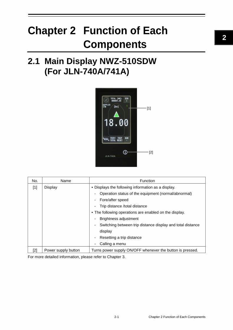
2-1 Chapter 2 Function of Each Components
2
Chapter 2 Function of Each Components
2.1 Main Display NWZ-510SDW (For JLN-740A/741A)
No. Name Function [1] Display • Displays the following information as a display.
- Operation status of the equipment (normal/abnormal) - Fore/after speed - Trip distance /total distance
• The following operations are enabled on the display. - Brightness adjustment - Switching between trip distance display and total distance
display - Resetting a trip distance - Calling a menu
[2] Power supply button Turns power supply ON/OFF whenever the button is pressed. For more detailed information, please refer to Chapter 3.
[1]
[2]
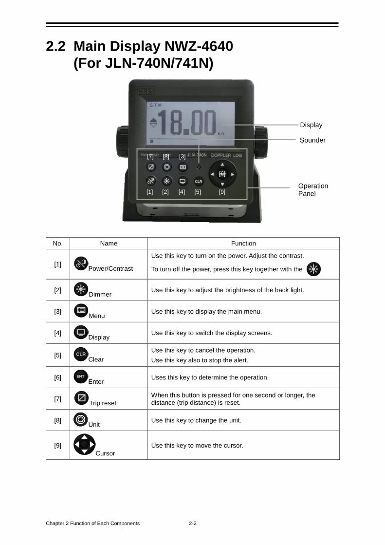
Chapter 2 Function of Each Components 2-2
2.2 Main Display NWZ-4640 (For JLN-740N/741N)
No. Name Function
[1] Power/Contrast
Use this key to turn on the power. Adjust the contrast.
To turn off the power, press this key together with the
[2] Dimmer Use this key to adjust the brightness of the back light.
[3] Menu Use this key to display the main menu.
[4] Display Use this key to switch the display screens.
[5] Clear Use this key to cancel the operation. Use this key also to stop the alert.
[6] Enter Uses this key to determine the operation.
[7] Trip reset When this button is pressed for one second or longer, the distance (trip distance) is reset.
[8] Unit Use this key to change the unit.
[9] Cursor
Use this key to move the cursor.
Operation Panel
Sounder
Display
[1] [2]
[3]
[4] [5]
[6]
[9]
[8] [7]
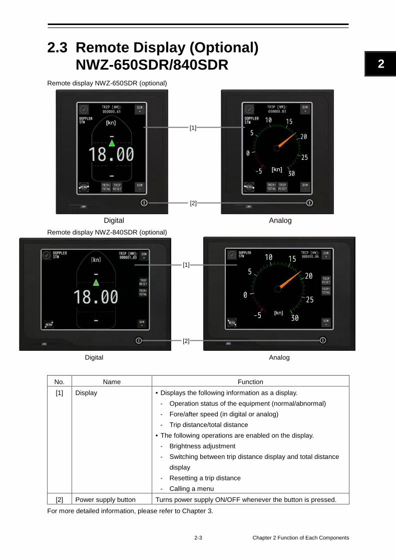
2-3 Chapter 2 Function of Each Components
2
2.3 Remote Display (Optional) NWZ-650SDR/840SDR
Remote display NWZ-650SDR (optional)
Digital Analog
Remote display NWZ-840SDR (optional)
Digital Analog
No. Name Function [1] Display • Displays the following information as a display.
- Operation status of the equipment (normal/abnormal) - Fore/after speed (in digital or analog) - Trip distance/total distance
• The following operations are enabled on the display. - Brightness adjustment - Switching between trip distance display and total distance
display - Resetting a trip distance - Calling a menu
[2] Power supply button Turns power supply ON/OFF whenever the button is pressed. For more detailed information, please refer to Chapter 3.
[1]
[1]
[2]
[2]
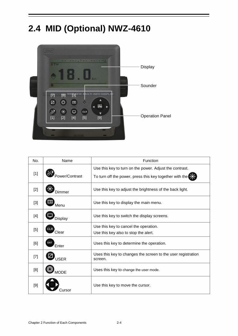
Chapter 2 Function of Each Components 2-4
2.4 MID (Optional) NWZ-4610
No. Name Function
[1] Power/Contrast
Use this key to turn on the power. Adjust the contrast.
To turn off the power, press this key together with the
[2] Dimmer Use this key to adjust the brightness of the back light.
[3] Menu Use this key to display the main menu.
[4] Display Use this key to switch the display screens.
[5] Clear Use this key to cancel the operation. Use this key also to stop the alert.
[6] Enter Uses this key to determine the operation.
[7] USER Uses this key to changes the screen to the user registration screen.
[8] MODE Uses this key to change the user mode.
[9] Cursor
Use this key to move the cursor.
Operation Panel
Display
Sounder
[1] [2]
[3]
[4] [5]
[6]
[9]
[8] [7]
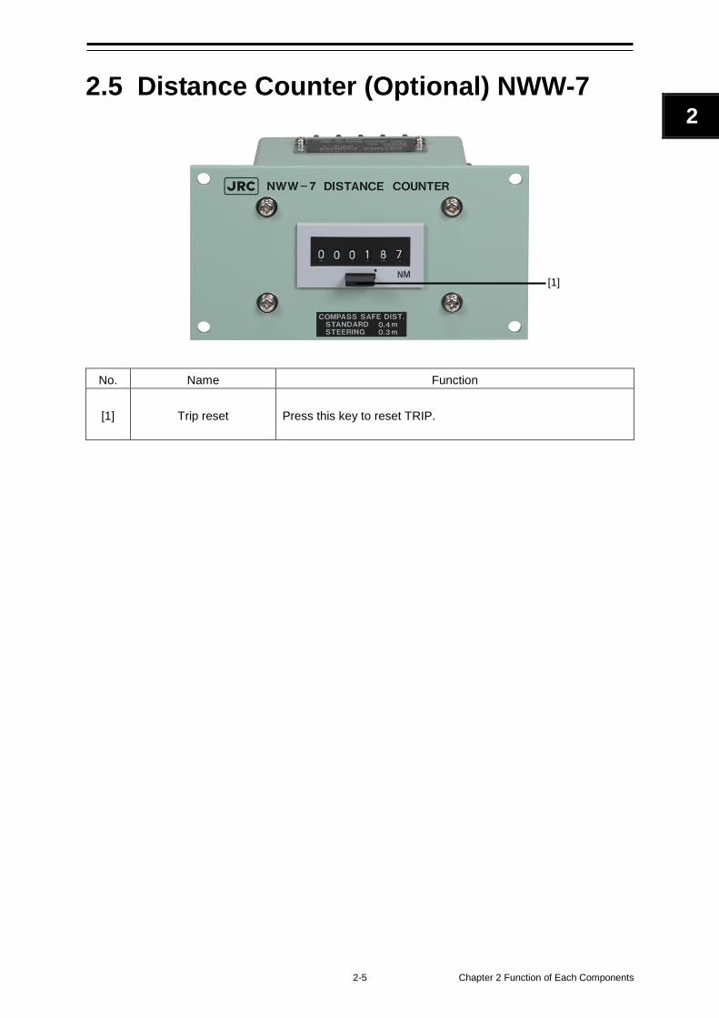
2-5 Chapter 2 Function of Each Components
2
2.5 Distance Counter (Optional) NWW-7
No. Name Function
[1] Trip reset Press this key to reset TRIP.
[1]

Chapter 2 Function of Each Components 2-6
(This page intentionally left blank)
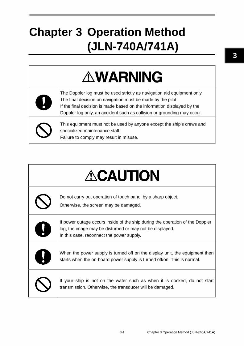
3-1 Chapter 3 Operation Method (JLN-740A/741A)
3 2
Chapter 3 Operation Method (JLN-740A/741A)
The Doppler log must be used strictly as navigation aid equipment only. The final decision on navigation must be made by the pilot. If the final decision is made based on the information displayed by the Doppler log only, an accident such as collision or grounding may occur.
This equipment must not be used by anyone except the ship’s crews and specialized maintenance staff. Failure to comply may result in misuse.
Do not carry out operation of touch panel by a sharp object.
Otherwise, the screen may be damaged.
If power outage occurs inside of the ship during the operation of the Doppler log, the image may be disturbed or may not be displayed. In this case, reconnect the power supply.
When the power supply is turned off on the display unit, the equipment then starts when the on-board power supply is turned off/on. This is normal.
If your ship is not on the water such as when it is docked, do not start transmission. Otherwise, the transducer will be damaged.
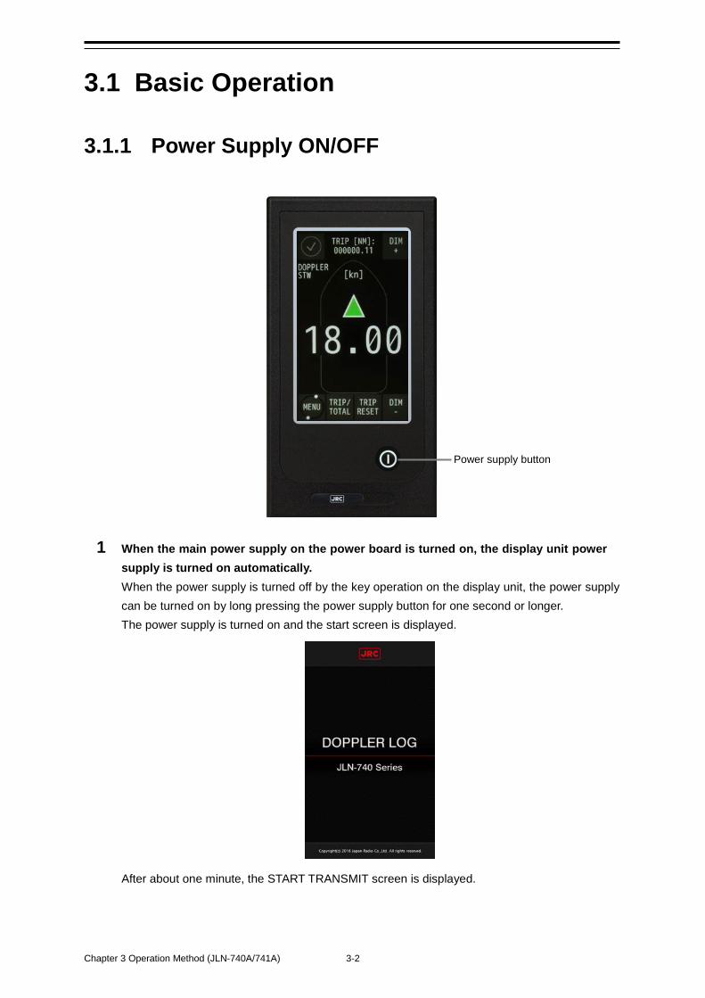
Chapter 3 Operation Method (JLN-740A/741A) 3-2
3.1 Basic Operation
3.1.1 Power Supply ON/OFF
1 When the main power supply on the power board is turned on, the display unit power supply is turned on automatically. When the power supply is turned off by the key operation on the display unit, the power supply can be turned on by long pressing the power supply button for one second or longer. The power supply is turned on and the start screen is displayed.
After about one minute, the START TRANSMIT screen is displayed.
Power supply button
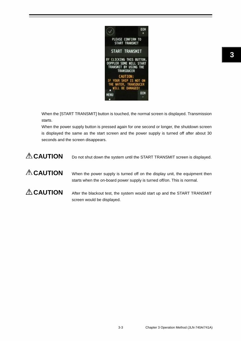
3-3 Chapter 3 Operation Method (JLN-740A/741A)
3 2
When the [START TRANSMIT] button is touched, the normal screen is displayed. Transmission starts. When the power supply button is pressed again for one second or longer, the shutdown screen is displayed the same as the start screen and the power supply is turned off after about 30 seconds and the screen disappears.
CAUTION Do not shut down the system until the START TRANSMIT screen is displayed.
CAUTION When the power supply is turned off on the display unit, the equipment then
starts when the on-board power supply is turned off/on. This is normal.
CAUTION After the blackout test, the system would start up and the START TRANSMIT screen would be displayed.
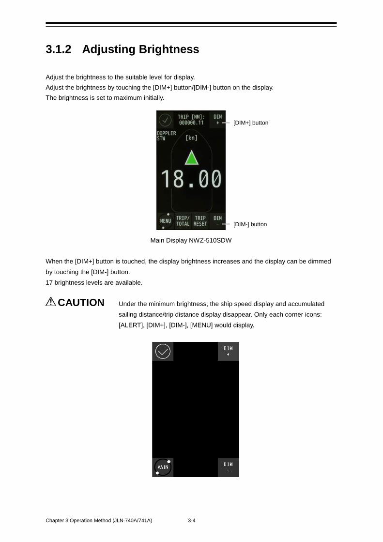
Chapter 3 Operation Method (JLN-740A/741A) 3-4
3.1.2 Adjusting Brightness Adjust the brightness to the suitable level for display. Adjust the brightness by touching the [DIM+] button/[DIM-] button on the display. The brightness is set to maximum initially.
Main Display NWZ-510SDW When the [DIM+] button is touched, the display brightness increases and the display can be dimmed by touching the [DIM-] button. 17 brightness levels are available.
CAUTION Under the minimum brightness, the ship speed display and accumulated sailing distance/trip distance display disappear. Only each corner icons: [ALERT], [DIM+], [DIM-], [MENU] would display.
[DIM+] button
[DIM-] button
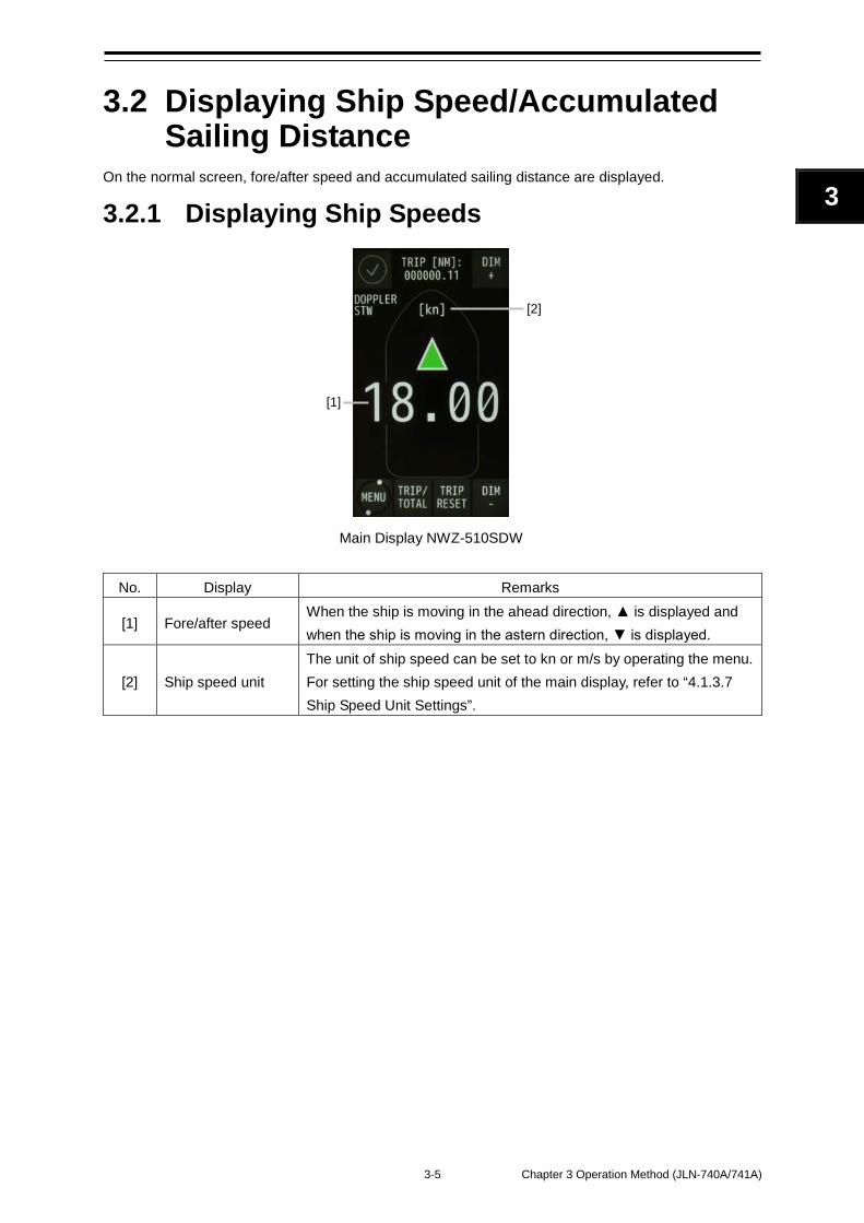
3-5 Chapter 3 Operation Method (JLN-740A/741A)
3 2
3.2 Displaying Ship Speed/Accumulated Sailing Distance
On the normal screen, fore/after speed and accumulated sailing distance are displayed.
3.2.1 Displaying Ship Speeds
Main Display NWZ-510SDW
No. Display Remarks
[1] Fore/after speed When the ship is moving in the ahead direction, ▲ is displayed and when the ship is moving in the astern direction, ▼ is displayed.
[2] Ship speed unit The unit of ship speed can be set to kn or m/s by operating the menu. For setting the ship speed unit of the main display, refer to “4.1.3.7 Ship Speed Unit Settings”.
[1]
[2]
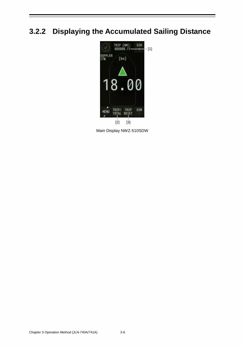
Chapter 3 Operation Method (JLN-740A/741A) 3-6
3.2.2 Displaying the Accumulated Sailing Distance
Main Display NWZ-510SDW
[1]
[2] [3]
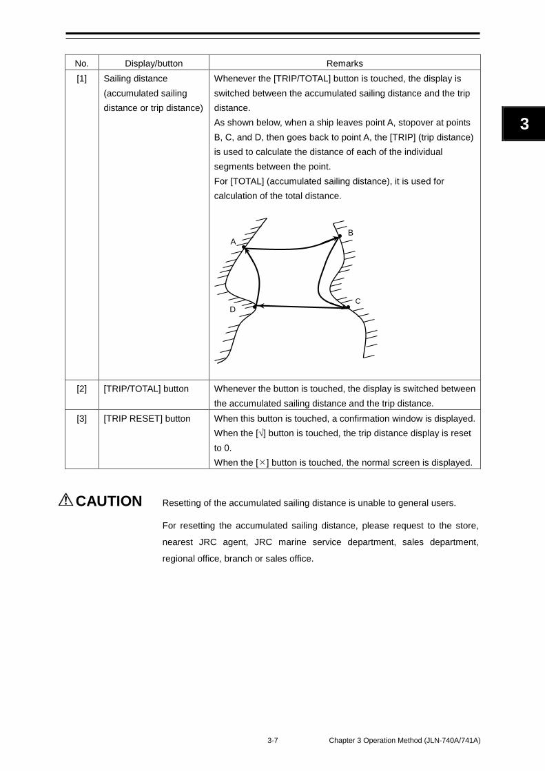
3-7 Chapter 3 Operation Method (JLN-740A/741A)
3 2
No. Display/button Remarks [1] Sailing distance
(accumulated sailing distance or trip distance)
Whenever the [TRIP/TOTAL] button is touched, the display is switched between the accumulated sailing distance and the trip distance. As shown below, when a ship leaves point A, stopover at points B, C, and D, then goes back to point A, the [TRIP] (trip distance) is used to calculate the distance of each of the individual segments between the point. For [TOTAL] (accumulated sailing distance), it is used for calculation of the total distance.
[2] [TRIP/TOTAL] button Whenever the button is touched, the display is switched between
the accumulated sailing distance and the trip distance. [3] [TRIP RESET] button When this button is touched, a confirmation window is displayed.
When the [√] button is touched, the trip distance display is reset to 0. When the [] button is touched, the normal screen is displayed.
CAUTION Resetting of the accumulated sailing distance is unable to general users.
For resetting the accumulated sailing distance, please request to the store,
nearest JRC agent, JRC marine service department, sales department,
regional office, branch or sales office.
A B
C D
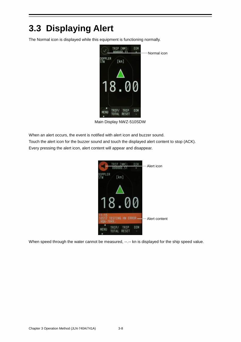
Chapter 3 Operation Method (JLN-740A/741A) 3-8
3.3 Displaying Alert The Normal icon is displayed while this equipment is functioning normally.
Main Display NWZ-510SDW When an alert occurs, the event is notified with alert icon and buzzer sound. Touch the alert icon for the buzzer sound and touch the displayed alert content to stop (ACK). Every pressing the alert icon, alert content will appear and disappear.
When speed through the water cannot be measured, --.-- kn is displayed for the ship speed value.
Normal icon
Alert icon
Alert content
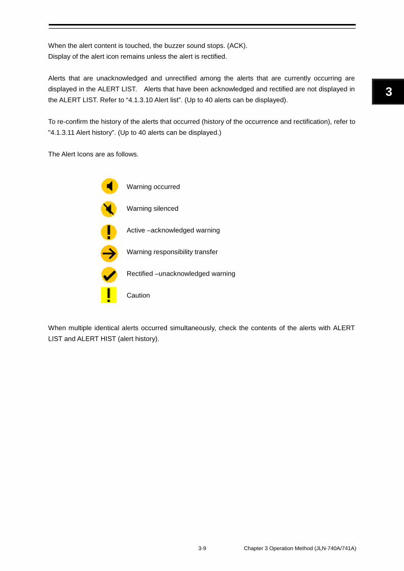
3-9 Chapter 3 Operation Method (JLN-740A/741A)
3 2
When the alert content is touched, the buzzer sound stops. (ACK). Display of the alert icon remains unless the alert is rectified. Alerts that are unacknowledged and unrectified among the alerts that are currently occurring are displayed in the ALERT LIST. Alerts that have been acknowledged and rectified are not displayed in the ALERT LIST. Refer to “4.1.3.10 Alert list”. (Up to 40 alerts can be displayed). To re-confirm the history of the alerts that occurred (history of the occurrence and rectification), refer to "4.1.3.11 Alert history”. (Up to 40 alerts can be displayed.) The Alert Icons are as follows.
Warning occurred Warning silenced Active –acknowledged warning Warning responsibility transfer Rectified –unacknowledged warning Caution
When multiple identical alerts occurred simultaneously, check the contents of the alerts with ALERT LIST and ALERT HIST (alert history).
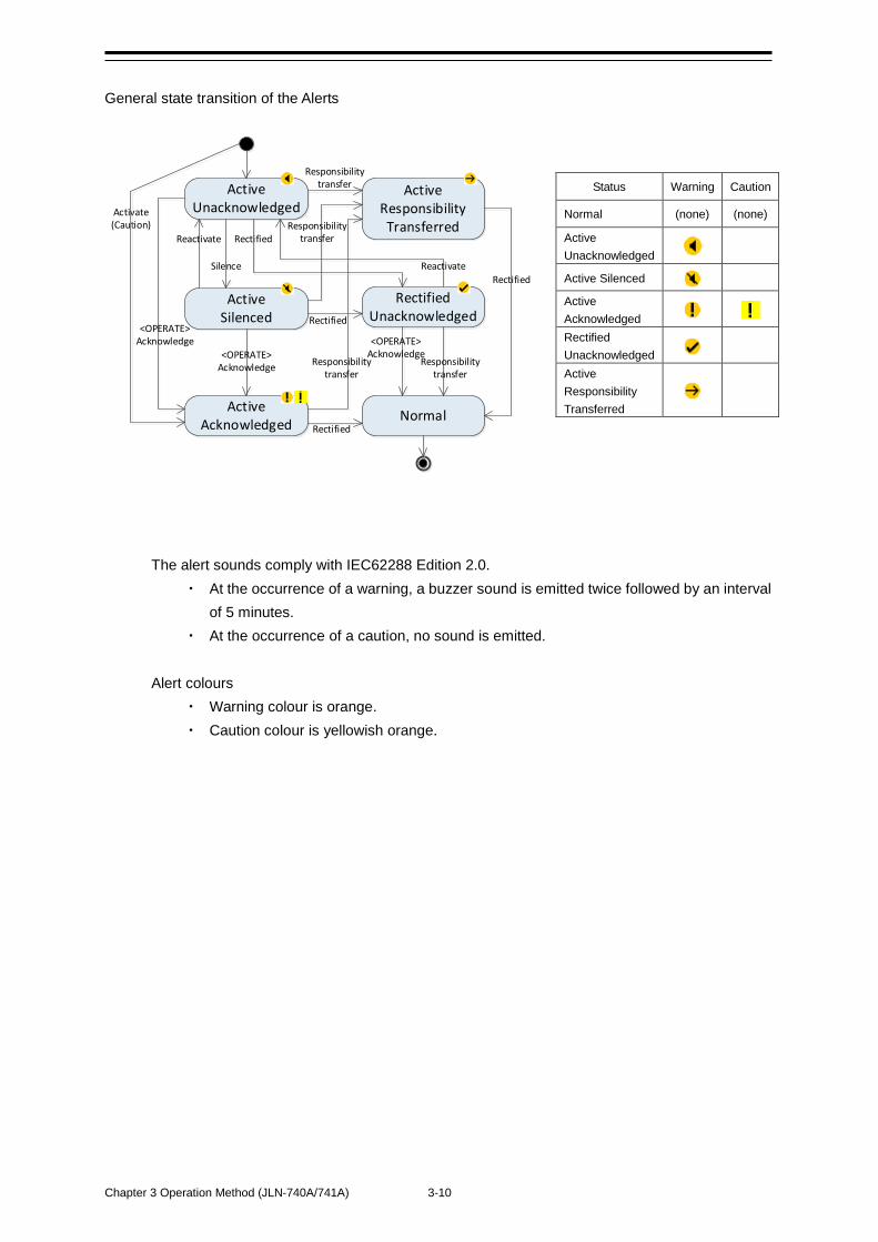
Chapter 3 Operation Method (JLN-740A/741A) 3-10
ActiveUnacknowledged
ActiveSilenced
ActiveAcknowledged Normal
RectifiedUnacknowledged
ActiveResponsibility Transferred
Activate(Caution)
Silence
<OPERATE>Acknowledge
<OPERATE>Acknowledge
Responsibilitytransfer
Responsibilitytransfer
Responsibilitytransfer
Rectified
Responsibilitytransfer
<OPERATE>Acknowledge
Rectified
Rectified
Reactivate
Reactivate
Rectified
General state transition of the Alerts
The alert sounds comply with IEC62288 Edition 2.0.
At the occurrence of a warning, a buzzer sound is emitted twice followed by an interval of 5 minutes.
At the occurrence of a caution, no sound is emitted.
Alert colours Warning colour is orange. Caution colour is yellowish orange.
Status Warning Caution
Normal (none) (none)
Active Unacknowledged
Active Silenced
Active Acknowledged
Rectified Unacknowledged
Active Responsibility Transferred
4-1 Chapter 4 Setting by Using Menus (JLN-740A/741A)
4
2
Chapter 4 Setting by Using Menus (JLN-740A/741A)
In JLN-740A/741A, various settings and adjustments can be performed by using the menus that are displayed.
Adjustments must be made by specialized service technicians. Incorrect settings may result in unstable operation, and this may lead to accidents or equipment failure.
Adjust the brightness of main display according to the surrounding lighting. In NWZ-510SDW, the setting of [NIGHT] may interfere with the recognition of display information. In NWZ-4640, the setting of [MINIMUM] may interfere with the recognition of display information.
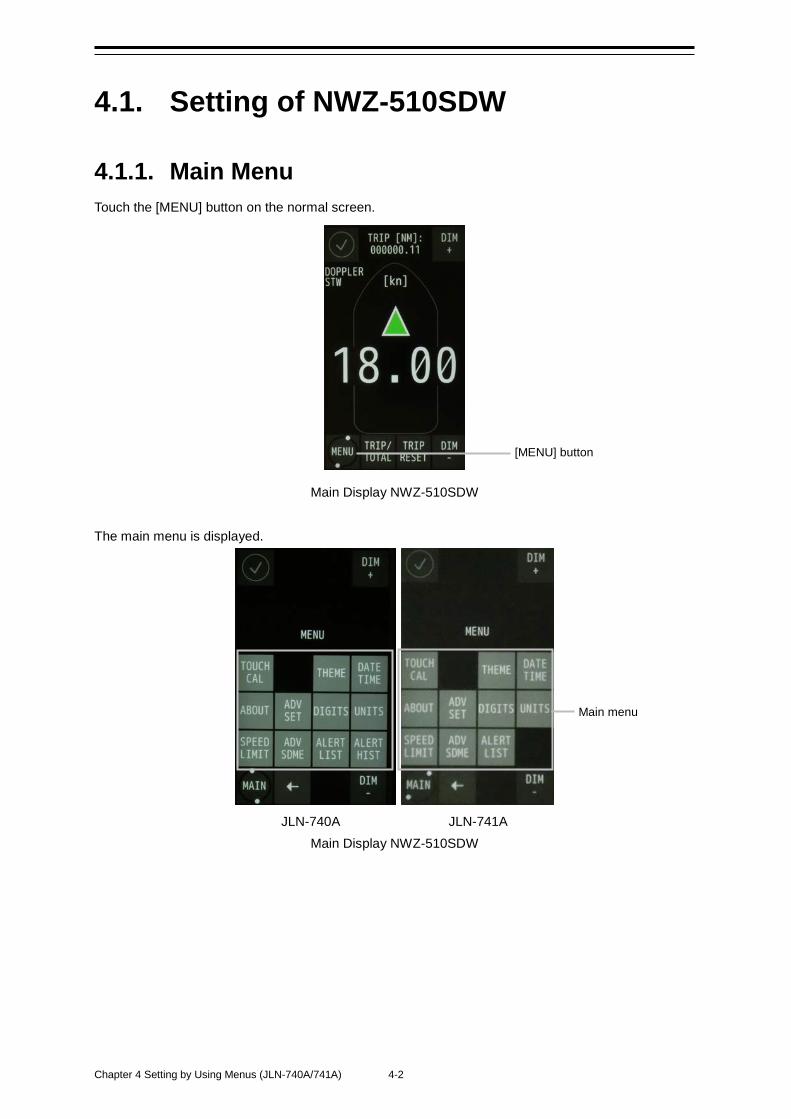
Chapter 4 Setting by Using Menus (JLN-740A/741A) 4-2
4.1. Setting of NWZ-510SDW
4.1.1. Main Menu Touch the [MENU] button on the normal screen.
Main Display NWZ-510SDW The main menu is displayed.
JLN-740A JLN-741A Main Display NWZ-510SDW
[MENU] button
Main menu
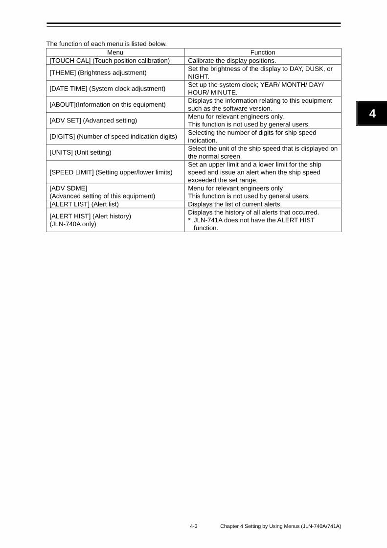
4-3 Chapter 4 Setting by Using Menus (JLN-740A/741A)
4
2
The function of each menu is listed below.
Menu Function [TOUCH CAL] (Touch position calibration) Calibrate the display positions.
[THEME] (Brightness adjustment) Set the brightness of the display to DAY, DUSK, or NIGHT.
[DATE TIME] (System clock adjustment) Set up the system clock; YEAR/ MONTH/ DAY/ HOUR/ MINUTE.
[ABOUT](Information on this equipment) Displays the information relating to this equipment such as the software version.
[ADV SET] (Advanced setting) Menu for relevant engineers only. This function is not used by general users.
[DIGITS] (Number of speed indication digits) Selecting the number of digits for ship speed indication.
[UNITS] (Unit setting) Select the unit of the ship speed that is displayed on the normal screen.
[SPEED LIMIT] (Setting upper/lower limits) Set an upper limit and a lower limit for the ship speed and issue an alert when the ship speed exceeded the set range.
[ADV SDME] (Advanced setting of this equipment)
Menu for relevant engineers only This function is not used by general users.
[ALERT LIST] (Alert list) Displays the list of current alerts.
[ALERT HIST] (Alert history) (JLN-740A only)
Displays the history of all alerts that occurred. * JLN-741A does not have the ALERT HIST
function.
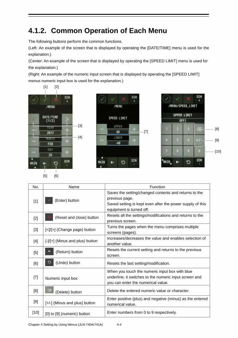
Chapter 4 Setting by Using Menus (JLN-740A/741A) 4-4
4.1.2. Common Operation of Each Menu The following buttons perform the common functions. (Left: An example of the screen that is displayed by operating the [DATE/TIME] menu is used for the explanation.) (Center: An example of the screen that is displayed by operating the [SPEED LIMIT] menu is used for the explanation.) (Right: An example of the numeric input screen that is displayed by operating the [SPEED LIMIT] menus numeric input box is used for the explanation.)
No. Name Function
[1] (Enter) button
Saves the setting/changed contents and returns to the previous page. Saved setting is kept even after the power supply of this equipment is turned off.
[2] (Reset and close) button Resets all the settings/modifications and returns to the previous screen.
[3] [<]/[>] (Change page) button Turns the pages when the menu comprises multiple screens (pages).
[4] [-]/[+] (Minus and plus) button Increases/decreases the value and enables selection of another value.
[5] (Return) button Resets the current setting and returns to the previous screen.
[6] (Undo) button Resets the last setting/modification.
[7] Numeric input box
When you touch the numeric input box with blue underline, it switches to the numeric input screen and you can enter the numerical value.
[8] (Delete) button Delete the entered numeric value or character.
[9] [+/-] (Minus and plus) button Enter positive (plus) and negative (minus) as the entered numerical value.
[10] [0] to [9] (numeric) button Enter numbers from 0 to 9 respectively.
[7]
[1] [2]
[3]
[4]
[10]
[9]
[8]
[5] [6]
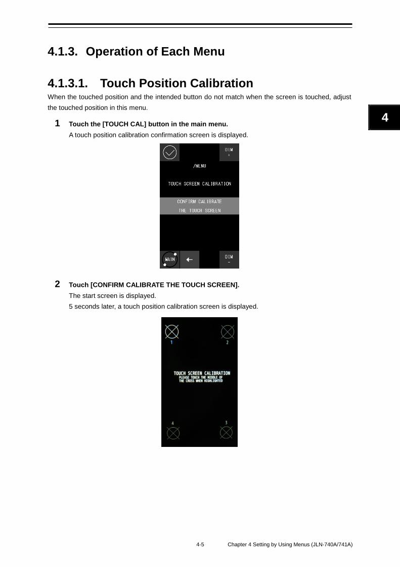
4-5 Chapter 4 Setting by Using Menus (JLN-740A/741A)
4
2
4.1.3. Operation of Each Menu
4.1.3.1. Touch Position Calibration When the touched position and the intended button do not match when the screen is touched, adjust the touched position in this menu.
1 Touch the [TOUCH CAL] button in the main menu. A touch position calibration confirmation screen is displayed.
2 Touch [CONFIRM CALIBRATE THE TOUCH SCREEN]. The start screen is displayed. 5 seconds later, a touch position calibration screen is displayed.
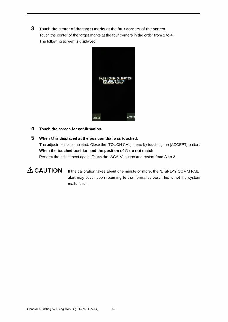
Chapter 4 Setting by Using Menus (JLN-740A/741A) 4-6
3 Touch the center of the target marks at the four corners of the screen. Touch the center of the target marks at the four corners in the order from 1 to 4. The following screen is displayed.
4 Touch the screen for confirmation.
5 When is displayed at the position that was touched: The adjustment is completed. Close the [TOUCH CAL] menu by touching the [ACCEPT] button. When the touched position and the position of do not match: Perform the adjustment again. Touch the [AGAIN] button and restart from Step 2.
CAUTION If the calibration takes about one minute or more, the “DISPLAY COMM FAIL” alert may occur upon returning to the normal screen. This is not the system malfunction.
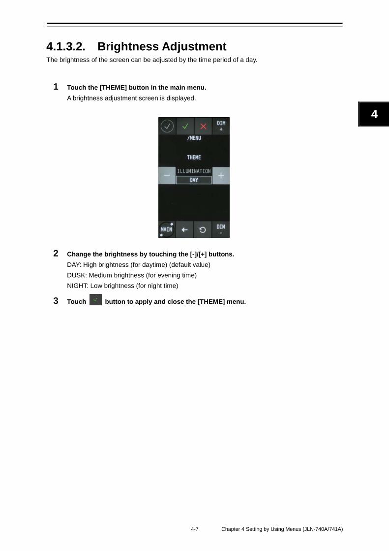
4-7 Chapter 4 Setting by Using Menus (JLN-740A/741A)
4
2
4.1.3.2. Brightness Adjustment The brightness of the screen can be adjusted by the time period of a day.
1 Touch the [THEME] button in the main menu. A brightness adjustment screen is displayed.
2 Change the brightness by touching the [-]/[+] buttons. DAY: High brightness (for daytime) (default value) DUSK: Medium brightness (for evening time) NIGHT: Low brightness (for night time)
3 Touch button to apply and close the [THEME] menu.
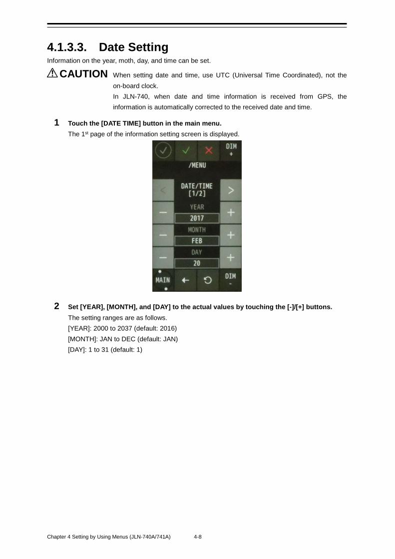
Chapter 4 Setting by Using Menus (JLN-740A/741A) 4-8
4.1.3.3. Date Setting Information on the year, moth, day, and time can be set.
CAUTION When setting date and time, use UTC (Universal Time Coordinated), not the on-board clock. In JLN-740, when date and time information is received from GPS, the information is automatically corrected to the received date and time.
1 Touch the [DATE TIME] button in the main menu. The 1st page of the information setting screen is displayed.
2 Set [YEAR], [MONTH], and [DAY] to the actual values by touching the [-]/[+] buttons. The setting ranges are as follows. [YEAR]: 2000 to 2037 (default: 2016) [MONTH]: JAN to DEC (default: JAN) [DAY]: 1 to 31 (default: 1)
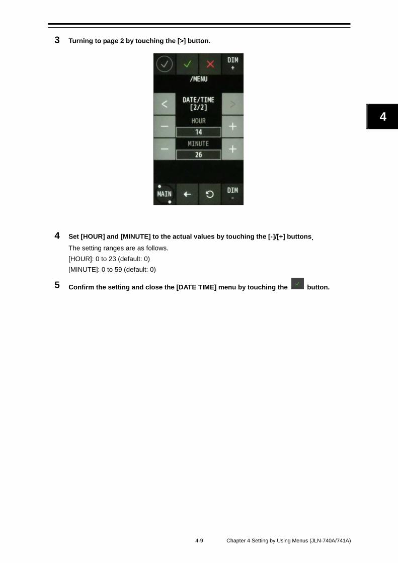
4-9 Chapter 4 Setting by Using Menus (JLN-740A/741A)
4
2
3 Turning to page 2 by touching the [>] button.
4 Set [HOUR] and [MINUTE] to the actual values by touching the [-]/[+] buttons. The setting ranges are as follows. [HOUR]: 0 to 23 (default: 0) [MINUTE]: 0 to 59 (default: 0)
5 Confirm the setting and close the [DATE TIME] menu by touching the button.
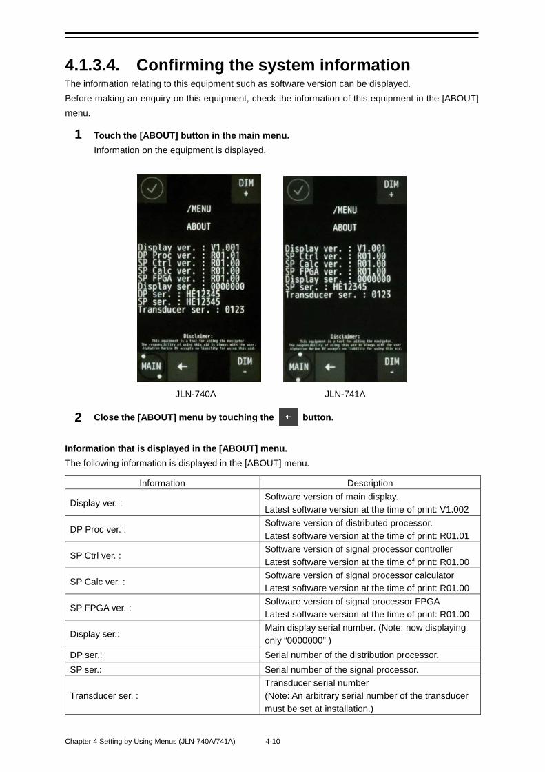
Chapter 4 Setting by Using Menus (JLN-740A/741A) 4-10
4.1.3.4. Confirming the system information The information relating to this equipment such as software version can be displayed. Before making an enquiry on this equipment, check the information of this equipment in the [ABOUT] menu.
1 Touch the [ABOUT] button in the main menu. Information on the equipment is displayed.
JLN-740A JLN-741A
2 Close the [ABOUT] menu by touching the button.
Information that is displayed in the [ABOUT] menu. The following information is displayed in the [ABOUT] menu.
Information Description
Display ver. : Software version of main display. Latest software version at the time of print: V1.002
DP Proc ver. : Software version of distributed processor. Latest software version at the time of print: R01.01
SP Ctrl ver. : Software version of signal processor controller Latest software version at the time of print: R01.00
SP Calc ver. : Software version of signal processor calculator Latest software version at the time of print: R01.00
SP FPGA ver. : Software version of signal processor FPGA Latest software version at the time of print: R01.00
Display ser.: Main display serial number. (Note: now displaying only “0000000” )
DP ser.: Serial number of the distribution processor. SP ser.: Serial number of the signal processor.
Transducer ser. : Transducer serial number (Note: An arbitrary serial number of the transducer must be set at installation.)
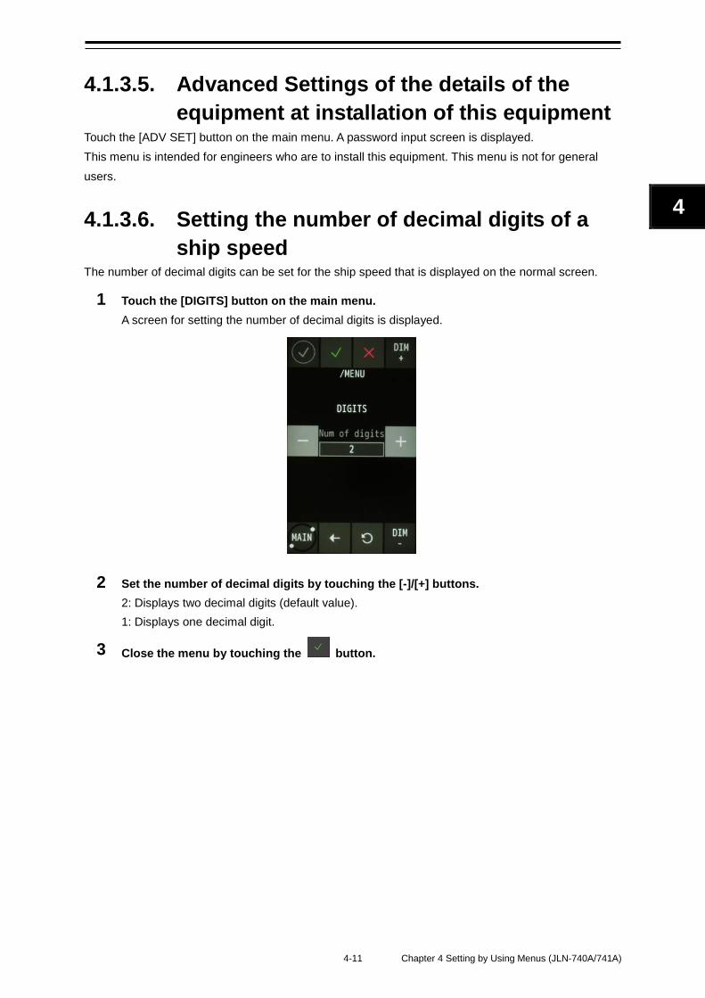
4-11 Chapter 4 Setting by Using Menus (JLN-740A/741A)
4
2
4.1.3.5. Advanced Settings of the details of the equipment at installation of this equipment
Touch the [ADV SET] button on the main menu. A password input screen is displayed. This menu is intended for engineers who are to install this equipment. This menu is not for general users.
4.1.3.6. Setting the number of decimal digits of a ship speed
The number of decimal digits can be set for the ship speed that is displayed on the normal screen.
1 Touch the [DIGITS] button on the main menu. A screen for setting the number of decimal digits is displayed.
2 Set the number of decimal digits by touching the [-]/[+] buttons. 2: Displays two decimal digits (default value). 1: Displays one decimal digit.
3 Close the menu by touching the button.

Chapter 4 Setting by Using Menus (JLN-740A/741A) 4-12
4.1.3.7. Ship Speed Unit Settings The unit of the ship speed that is displayed on the normal screen can be set.
1 Touch the [UNITS] button in the main menu. A screen for setting a unit is displayed.
2 Change the unit by touching the [-]/[+] buttons. kn: knot (default value) m/s: meter per second
3 Close the [UNITS] menu by touching the button.
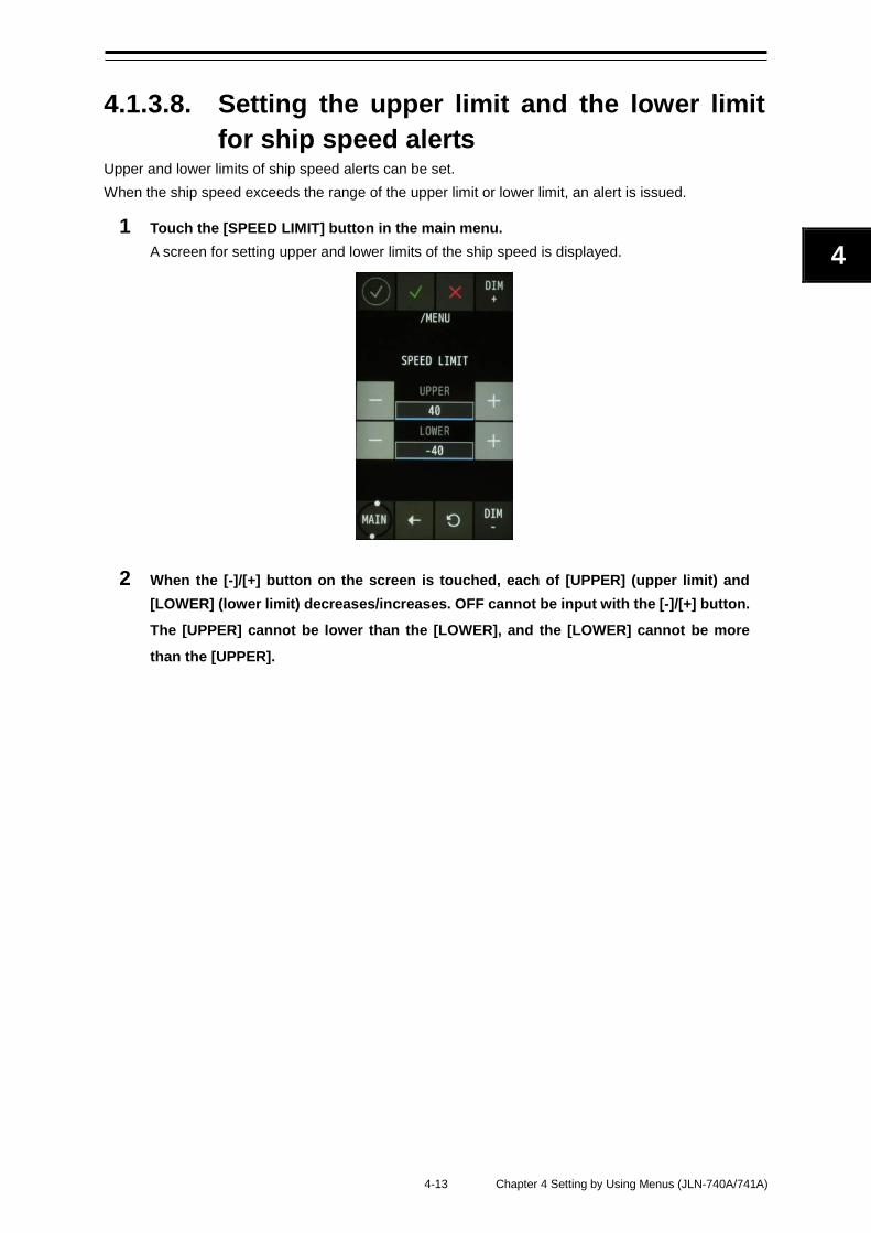
4-13 Chapter 4 Setting by Using Menus (JLN-740A/741A)
4
2
4.1.3.8. Setting the upper limit and the lower limit for ship speed alerts
Upper and lower limits of ship speed alerts can be set. When the ship speed exceeds the range of the upper limit or lower limit, an alert is issued.
1 Touch the [SPEED LIMIT] button in the main menu. A screen for setting upper and lower limits of the ship speed is displayed.
2 When the [-]/[+] button on the screen is touched, each of [UPPER] (upper limit) and [LOWER] (lower limit) decreases/increases. OFF cannot be input with the [-]/[+] button.
The [UPPER] cannot be lower than the [LOWER], and the [LOWER] cannot be more
than the [UPPER].
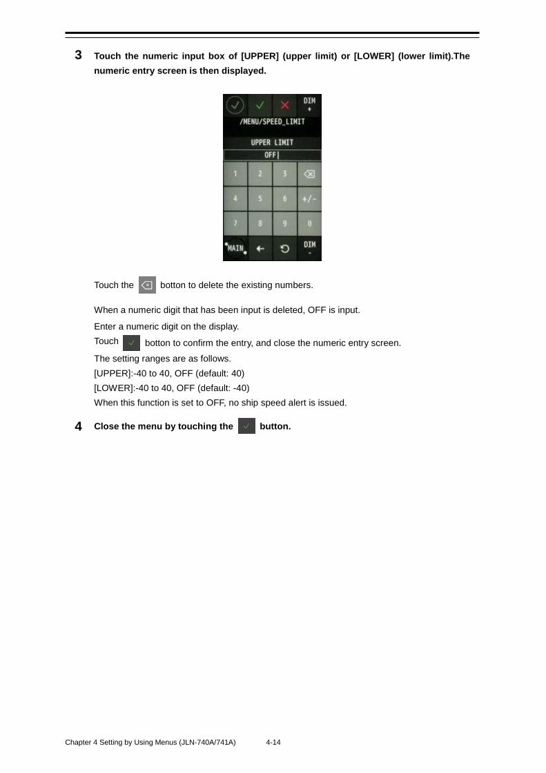
Chapter 4 Setting by Using Menus (JLN-740A/741A) 4-14
3 Touch the numeric input box of [UPPER] (upper limit) or [LOWER] (lower limit).The numeric entry screen is then displayed.
Touch the botton to delete the existing numbers.
When a numeric digit that has been input is deleted, OFF is input.
Enter a numeric digit on the display. Touch botton to confirm the entry, and close the numeric entry screen.
The setting ranges are as follows. [UPPER]:-40 to 40, OFF (default: 40) [LOWER]:-40 to 40, OFF (default: -40) When this function is set to OFF, no ship speed alert is issued.
4 Close the menu by touching the button.
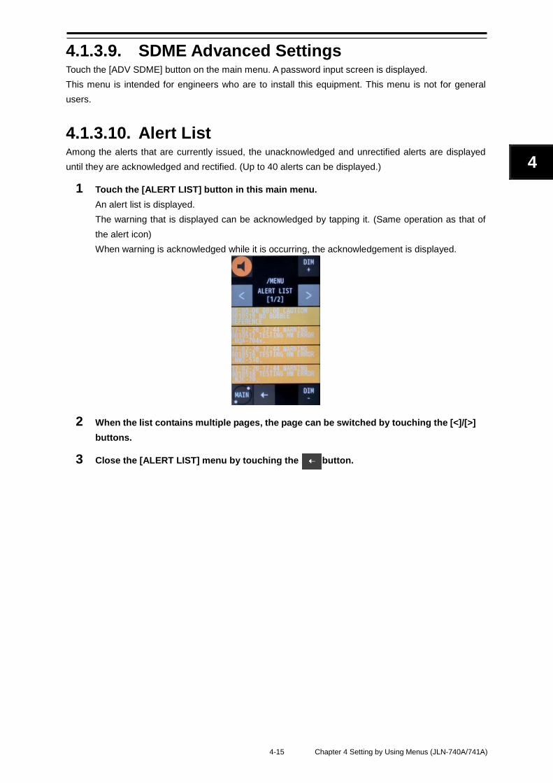
4-15 Chapter 4 Setting by Using Menus (JLN-740A/741A)
4
2
4.1.3.9. SDME Advanced Settings Touch the [ADV SDME] button on the main menu. A password input screen is displayed. This menu is intended for engineers who are to install this equipment. This menu is not for general users.
4.1.3.10. Alert List Among the alerts that are currently issued, the unacknowledged and unrectified alerts are displayed until they are acknowledged and rectified. (Up to 40 alerts can be displayed.)
1 Touch the [ALERT LIST] button in this main menu. An alert list is displayed. The warning that is displayed can be acknowledged by tapping it. (Same operation as that of the alert icon) When warning is acknowledged while it is occurring, the acknowledgement is displayed.
2 When the list contains multiple pages, the page can be switched by touching the [<]/[>] buttons.
3 Close the [ALERT LIST] menu by touching the button.
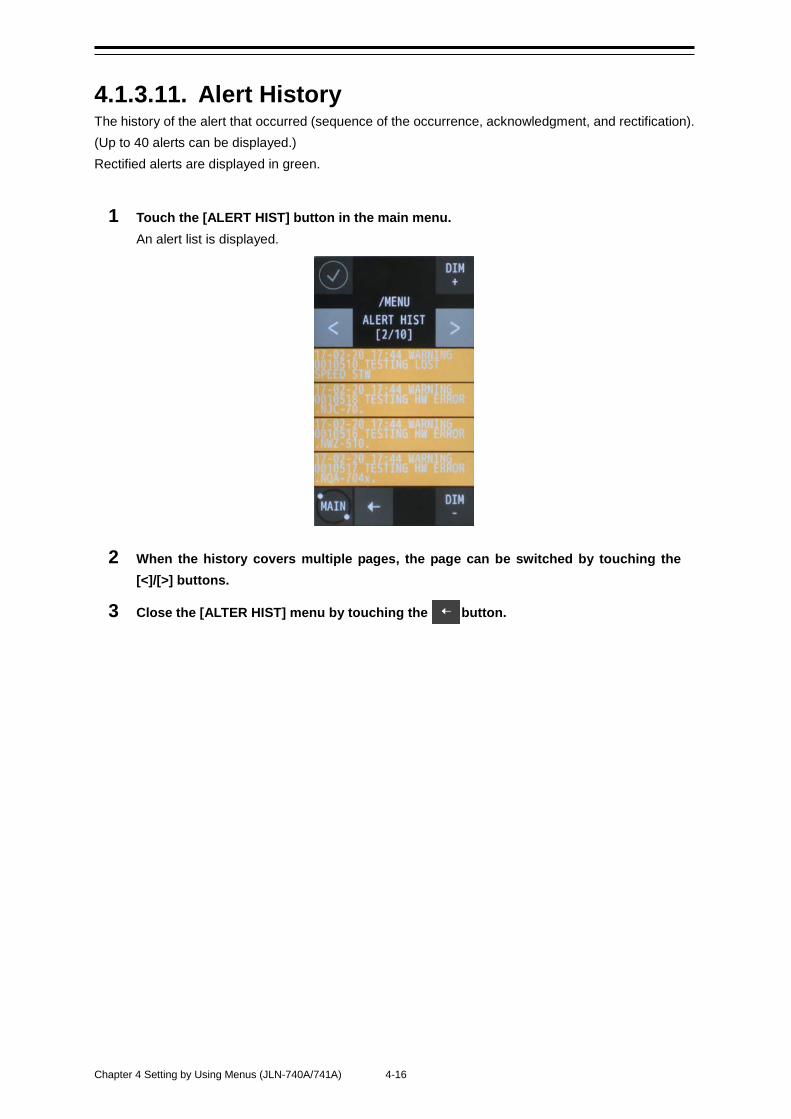
Chapter 4 Setting by Using Menus (JLN-740A/741A) 4-16
4.1.3.11. Alert History The history of the alert that occurred (sequence of the occurrence, acknowledgment, and rectification). (Up to 40 alerts can be displayed.) Rectified alerts are displayed in green.
1 Touch the [ALERT HIST] button in the main menu. An alert list is displayed.
2 When the history covers multiple pages, the page can be switched by touching the [<]/[>] buttons.
3 Close the [ALTER HIST] menu by touching the button.

4-17 Chapter 4 Setting by Using Menus (JLN-740A/741A)
4
2
4.2. Alert
4.2.1. JLN-740A Alert list
Alert message WARNING CAUTION Possible cause LOST SPEED STW STW (fore/after) could not be measured.
HW ERROR (NWZ-510) Main display hardware error HW ERROR (NQA-7040) Distribution processor hardware error
HW ERROR (NJC-70) Signal processor hardware error OVER SPEED STW STW exceed the set speed limit range.
BUBBLE DETECTED Bubble was detected.
NO BUBBLE REFERENCE No bubble detection reference data
TX/RX STOP Transmission/reception power for the transceiver stopped.
CPU STOP (CDC-7400) CPU of NJC70S/CDC-7400 is not operating.
HW ERROR (CDC-7400) FPGA of NJC70S/CDC-7400 is not operating.
PLEASE SET DATE-TIME No date and time are input.
DISPLAY COMM. FAIL Communication with the main display unit was disconnected.
SENSOR COMM. FAIL Communication with the signal processor was disconnected.
CPU1 MISMATCH (1MIN REMAINS) CDC-7400 CPU version does not match.
One minute remains for update time. CPU2 MISMATCH (1MIN REMAINS) CDC-7400 CPU version does not match.
One minute remains for update time.
FPGA1 MISMATCH (10MIN REMAINS)
CDC-7400 FPGA version does not match. Ten minutes remain for update time.
PARSING OF NMEA (Talker+ID) FAILED NMEA (Talker+ID) could not analysis.
Alert with main display only. INVALID CHECKSUM OF
NMEA (Talker+ID) SENTENCE Invalid checksum of NMEA (Talker+ID). Alert with main display only.
(ID) TIMED OUT (ID) timed out. Alert with main display only.
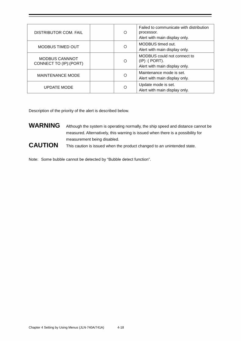
Chapter 4 Setting by Using Menus (JLN-740A/741A) 4-18
DISTRIBUTOR COM. FAIL Failed to communicate with distribution processor. Alert with main display only.
MODBUS TIMED OUT MODBUS timed out. Alert with main display only.
MODBUS CANNNOT CONNECT TO (IP):(PORT)
MODBUS could not connect to (IP) :( PORT). Alert with main display only.
MAINTENANCE MODE Maintenance mode is set. Alert with main display only.
UPDATE MODE Update mode is set. Alert with main display only.
Description of the priority of the alert is described below.
WARNING Although the system is operating normally, the ship speed and distance cannot be measured. Alternatively, this warning is issued when there is a possibility for measurement being disabled.
CAUTION This caution is issued when the product changed to an unintended state. Note: Some bubble cannot be detected by “Bubble detect function”.
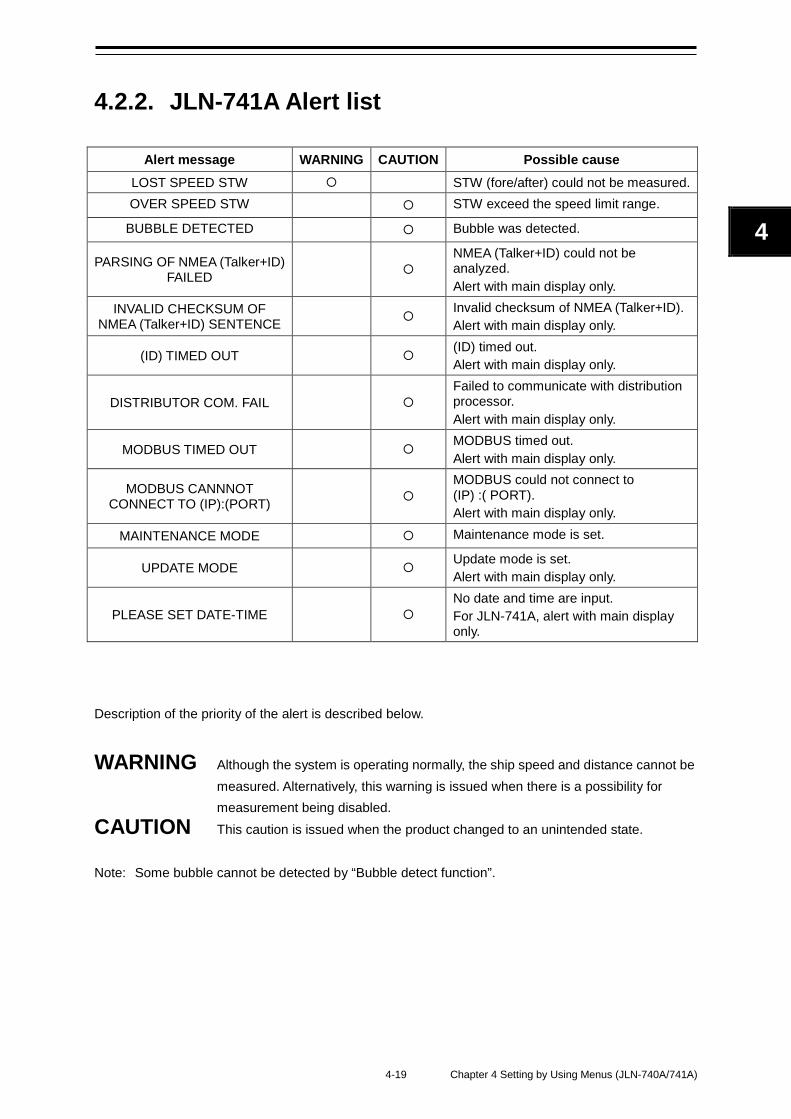
4-19 Chapter 4 Setting by Using Menus (JLN-740A/741A)
4
2
4.2.2. JLN-741A Alert list
Alert message WARNING CAUTION Possible cause LOST SPEED STW STW (fore/after) could not be measured. OVER SPEED STW STW exceed the speed limit range.
BUBBLE DETECTED Bubble was detected.
PARSING OF NMEA (Talker+ID) FAILED
NMEA (Talker+ID) could not be analyzed. Alert with main display only.
INVALID CHECKSUM OF NMEA (Talker+ID) SENTENCE Invalid checksum of NMEA (Talker+ID).
Alert with main display only.
(ID) TIMED OUT (ID) timed out. Alert with main display only.
DISTRIBUTOR COM. FAIL Failed to communicate with distribution processor. Alert with main display only.
MODBUS TIMED OUT MODBUS timed out. Alert with main display only.
MODBUS CANNNOT CONNECT TO (IP):(PORT)
MODBUS could not connect to (IP) :( PORT). Alert with main display only.
MAINTENANCE MODE Maintenance mode is set.
UPDATE MODE Update mode is set. Alert with main display only.
PLEASE SET DATE-TIME No date and time are input. For JLN-741A, alert with main display only.
Description of the priority of the alert is described below.
WARNING Although the system is operating normally, the ship speed and distance cannot be measured. Alternatively, this warning is issued when there is a possibility for measurement being disabled.
CAUTION This caution is issued when the product changed to an unintended state. Note: Some bubble cannot be detected by “Bubble detect function”.
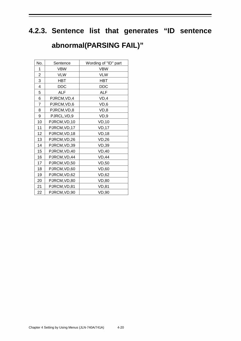
Chapter 4 Setting by Using Menus (JLN-740A/741A) 4-20
4.2.3. Sentence list that generates “ID sentence
abnormal(PARSING FAIL)”
No. Sentence Wording of "ID" part 1 VBW VBW 2 VLW VLW 3 HBT HBT 4 DDC DDC 5 ALF ALF 6 PJRCM,VD,4 VD,4 7 PJRCM,VD,6 VD,6 8 PJRCM,VD,8 VD,8 9 PJRCL,VD,9 VD,9
10 PJRCM,VD,10 VD,10 11 PJRCM,VD,17 VD,17 12 PJRCM,VD,18 VD,18 13 PJRCM,VD,26 VD,26 14 PJRCM,VD,39 VD,39 15 PJRCM,VD,40 VD,40 16 PJRCM,VD,44 VD,44 17 PJRCM,VD,50 VD,50 18 PJRCM,VD,60 VD,60 19 PJRCM,VD,62 VD,62 20 PJRCM,VD,80 VD,80 21 PJRCM,VD,81 VD,81 22 PJRCM,VD,90 VD,90
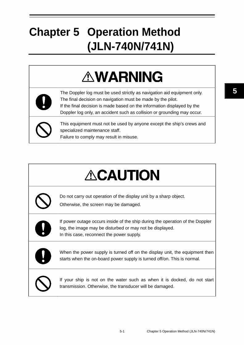
5-1 Chapter 5 Operation Method (JLN-740N/741N)
5
Chapter 5 Operation Method (JLN-740N/741N)
The Doppler log must be used strictly as navigation aid equipment only. The final decision on navigation must be made by the pilot. If the final decision is made based on the information displayed by the Doppler log only, an accident such as collision or grounding may occur.
This equipment must not be used by anyone except the ship’s crews and specialized maintenance staff. Failure to comply may result in misuse.
Do not carry out operation of the display unit by a sharp object.
Otherwise, the screen may be damaged.
If power outage occurs inside of the ship during the operation of the Doppler log, the image may be disturbed or may not be displayed. In this case, reconnect the power supply.
When the power supply is turned off on the display unit, the equipment then starts when the on-board power supply is turned off/on. This is normal.
If your ship is not on the water such as when it is docked, do not start transmission. Otherwise, the transducer will be damaged.
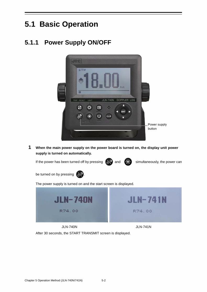
Chapter 5 Operation Method (JLN-740N/741N) 5-2
5.1 Basic Operation
5.1.1 Power Supply ON/OFF
1 When the main power supply on the power board is turned on, the display unit power supply is turned on automatically.
If the power has been turned off by pressing and simultaneously, the power can
be turned on by pressing .
The power supply is turned on and the start screen is displayed.
JLN-740N JLN-741N
After 30 seconds, the START TRANSMIT screen is displayed.
Power supply button
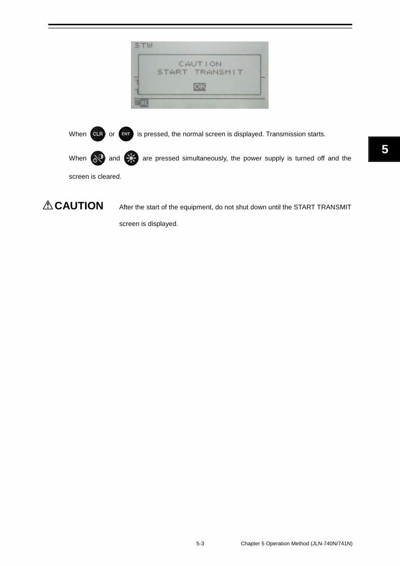
5-3 Chapter 5 Operation Method (JLN-740N/741N)
5
When or is pressed, the normal screen is displayed. Transmission starts.
When and are pressed simultaneously, the power supply is turned off and the
screen is cleared.
CAUTION After the start of the equipment, do not shut down until the START TRANSMIT
screen is displayed.
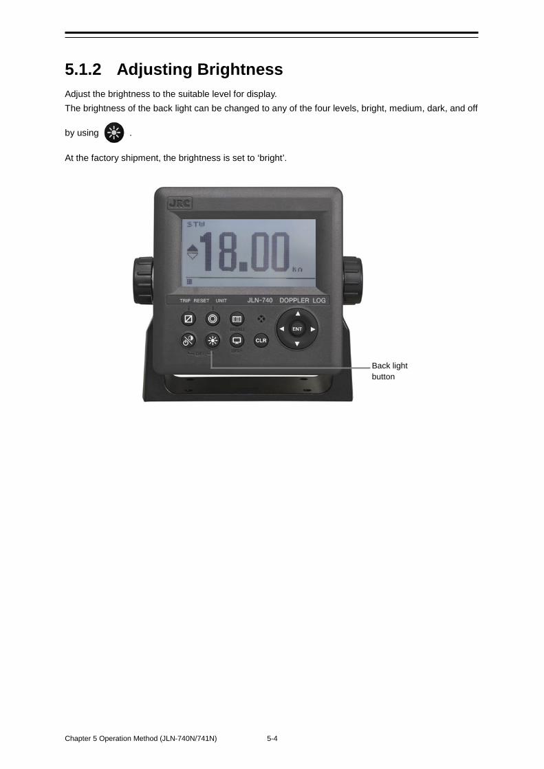
Chapter 5 Operation Method (JLN-740N/741N) 5-4
5.1.2 Adjusting Brightness Adjust the brightness to the suitable level for display. The brightness of the back light can be changed to any of the four levels, bright, medium, dark, and off
by using .
At the factory shipment, the brightness is set to ‘bright’.
Back light button
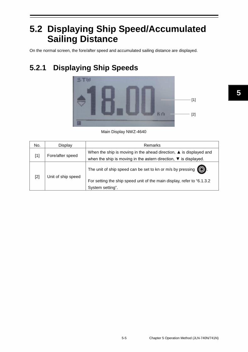
5-5 Chapter 5 Operation Method (JLN-740N/741N)
5
5.2 Displaying Ship Speed/Accumulated Sailing Distance
On the normal screen, the fore/after speed and accumulated sailing distance are displayed.
5.2.1 Displaying Ship Speeds
Main Display NWZ-4640
No. Display Remarks
[1] Fore/after speed When the ship is moving in the ahead direction, ▲ is displayed and when the ship is moving in the astern direction, ▼ is displayed.
[2] Unit of ship speed
The unit of ship speed can be set to kn or m/s by pressing .
For setting the ship speed unit of the main display, refer to “6.1.3.2 System setting”.
[1]
[2]
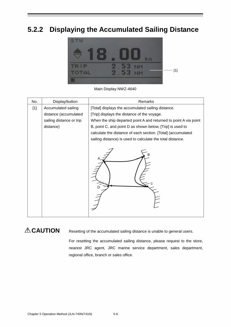
Chapter 5 Operation Method (JLN-740N/741N) 5-6
5.2.2 Displaying the Accumulated Sailing Distance
Main Display NWZ-4640
No. Display/button Remarks [1] Accumulated sailing
distance (accumulated sailing distance or trip distance)
[Total] displays the accumulated sailing distance. [Trip] displays the distance of the voyage. When the ship departed point A and returned to point A via point B, point C, and point D as shown below, [Trip] is used to calculate the distance of each section. [Total] (accumulated sailing distance) is used to calculate the total distance.
CAUTION Resetting of the accumulated sailing distance is unable to general users.
For resetting the accumulated sailing distance, please request to the store,
nearest JRC agent, JRC marine service department, sales department,
regional office, branch or sales office.
A B
C D
[1]
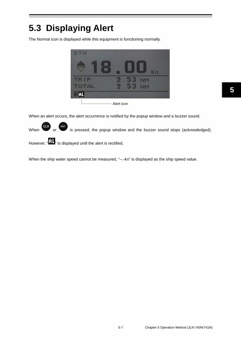
5-7 Chapter 5 Operation Method (JLN-740N/741N)
5
5.3 Displaying Alert The Normal icon is displayed while this equipment is functioning normally.
When an alert occurs, the alert occurrence is notified by the popup window and a buzzer sound.
When or is pressed, the popup window and the buzzer sound stops (acknowledged).
However, “ ” is displayed until the alert is rectified.
When the ship water speed cannot be measured, “--.-kn” is displayed as the ship speed value.
Alert icon

Chapter 5 Operation Method (JLN-740N/741N) 5-8
(This page intentionally left blank)
6-1 Chapter 6 Setting by Using Menus (JLN-740N/741N)
6
Chapter 6 Setting by Using Menus (JLN-740N/741N)
On JLN-740N/741N, various configurations can be set and adjusted by pressing the buttons.
Adjustments must be made by specialized service technicians. Incorrect settings may result in unstable operation, and this may lead to accidents or equipment failure.
Adjust the brightness of main display according to the surrounding lighting. In NWZ-510SDW, the setting of [NIGHT] may interfere with the recognition of display information. In NWZ-4640, the setting of [MINIMUM] may interfere with the recognition of display information.
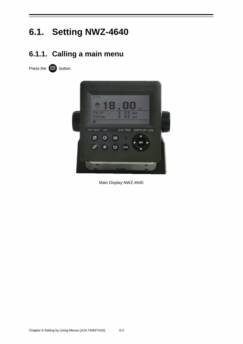
Chapter 6 Setting by Using Menus (JLN-740N/741N) 6-2
6.1. Setting NWZ-4640
6.1.1. Calling a main menu
Press the button.
Main Display NWZ-4640
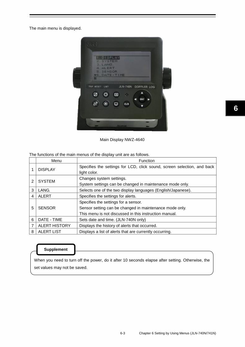
6-3 Chapter 6 Setting by Using Menus (JLN-740N/741N)
6
The main menu is displayed.
Main Display NWZ-4640
The functions of the main menus of the display unit are as follows. Menu Function
1 DISPLAY Specifies the settings for LCD, click sound, screen selection, and back light color.
2 SYSTEM Changes system settings. System settings can be changed in maintenance mode only.
3 LANG. Selects one of the two display languages (English/Japanese). 4 ALERT Specifies the settings for alerts.
5 SENSOR Specifies the settings for a sensor. Sensor setting can be changed in maintenance mode only. This menu is not discussed in this instruction manual.
6 DATE - TIME Sets date and time. (JLN-740N only) 7 ALERT HISTORY Displays the history of alerts that occurred. 8 ALERT LIST Displays a list of alerts that are currently occurring.
When you need to turn off the power, do it after 10 seconds elapse after setting. Otherwise, the
set values may not be saved.
Supplement
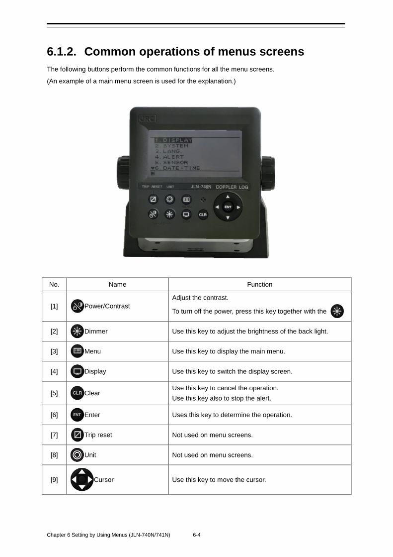
Chapter 6 Setting by Using Menus (JLN-740N/741N) 6-4
6.1.2. Common operations of menus screens The following buttons perform the common functions for all the menu screens.
(An example of a main menu screen is used for the explanation.)
No. Name Function
[1] Power/Contrast Adjust the contrast.
To turn off the power, press this key together with the
[2] Dimmer Use this key to adjust the brightness of the back light.
[3] Menu Use this key to display the main menu.
[4] Display Use this key to switch the display screen.
[5] Clear Use this key to cancel the operation. Use this key also to stop the alert.
[6] Enter Uses this key to determine the operation.
[7] Trip reset Not used on menu screens.
[8] Unit Not used on menu screens.
[9] Cursor Use this key to move the cursor.
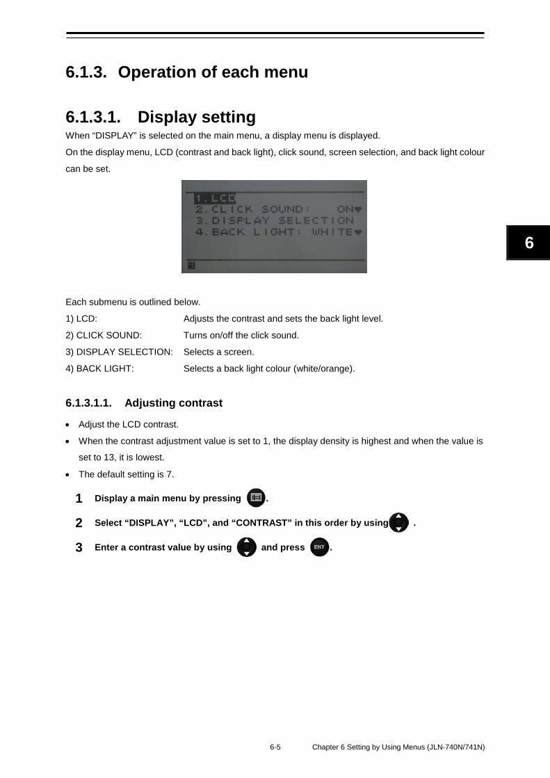
6-5 Chapter 6 Setting by Using Menus (JLN-740N/741N)
6
6.1.3. Operation of each menu
6.1.3.1. Display setting When “DISPLAY” is selected on the main menu, a display menu is displayed.
On the display menu, LCD (contrast and back light), click sound, screen selection, and back light colour
can be set.
Each submenu is outlined below.
1) LCD: Adjusts the contrast and sets the back light level.
2) CLICK SOUND: Turns on/off the click sound.
3) DISPLAY SELECTION: Selects a screen.
4) BACK LIGHT: Selects a back light colour (white/orange).
6.1.3.1.1. Adjusting contrast
• Adjust the LCD contrast.
• When the contrast adjustment value is set to 1, the display density is highest and when the value is
set to 13, it is lowest.
• The default setting is 7.
1 Display a main menu by pressing .
2 Select “DISPLAY”, “LCD”, and “CONTRAST” in this order by using .
3 Enter a contrast value by using and press .
Chapter 6 Setting by Using Menus (JLN-740N/741N) 6-6
6.1.3.1.2. Adjusting back light
• Brightness of the back light can be changed by using . Four levels of brightness are
available: bright, medium, dark, and off.
This section shows how to set a value of each brightness level.
1 Display a main menu by pressing .
2 Select “DISPLAY”, “LCD”, and “DIMMER MAXIMUM/TYPICAL/MINIMUM” in this order
by using .
3 Enter a brightness level value by using and press .
6.1.3.1.3. Setting a click sound
• Turn on/off a key-operation click sound.
ON: Enables a click sound. When the key is pressed, a “pip” sound is emitted. When the operation
is invalid, a “pip pip pip” sound is emitted.
OFF: Disables a click sound.
1 Display a main menu by pressing .
2 Select “DISPLAY” and “CLICK SOUND” in that order by using .
3 Select “ON” or “OFF” by using and press .
Enter the highest value in “MAXIMUM” and the lowest value in “MINIMUM”.
Supplement
6-7 Chapter 6 Setting by Using Menus (JLN-740N/741N)
6
6.1.3.1.4. Setting a display screen
Up to six display screens can be registered in this display unit.
The display screen can be switched either manually by using or automatically (auto screen
function).
The auto screen function enables the setting of a switching interval. Switching can also be notified by
emitting a sounder.
Only the integer section or the decimal section of an indication character can be expanded and
displayed. (Display mode)
Set the auto screen function and the display mode in "STEP3."
The screen structures of each display screen include customised screens that can be set freely, special
screens that do not allow any setting, and graphic screens. The contents to be displayed on the display
screen can be selected.
The screen selection procedure is as follows.
STEP1 Select a display screen.
STEP2 Select a screen structure.
STEP3 Select the display contents.
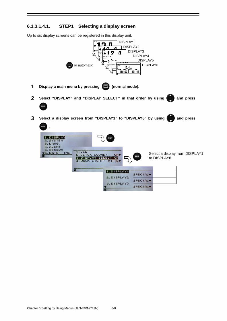
Chapter 6 Setting by Using Menus (JLN-740N/741N) 6-8
6.1.3.1.4.1. STEP1 Selecting a display screen
Up to six display screens can be registered in this display unit.
1 Display a main menu by pressing (normal mode).
2 Select “DISPLAY” and “DISPLAY SELECT” in that order by using and press
.
3 Select a display screen from “DISPLAY1” to “DISPLAY6” by using and press
.
or automatic
DISPLAY1 DISPLAY2
DISPLAY3 DISPLAY4
DISPLAY5 DISPLAY6
Select a display from DISPLAY1 to DISPLAY6
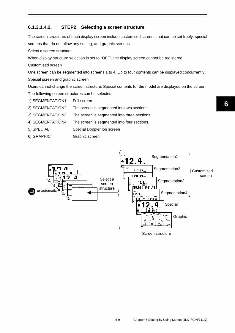
6-9 Chapter 6 Setting by Using Menus (JLN-740N/741N)
6
6.1.3.1.4.2. STEP2 Selecting a screen structure
The screen structures of each display screen include customised screens that can be set freely, special
screens that do not allow any setting, and graphic screens.
Select a screen structure.
When display structure selection is set to “OFF”, the display screen cannot be registered.
Customised screen
One screen can be segmented into screens 1 to 4. Up to four contents can be displayed concurrently.
Special screen and graphic screen
Users cannot change the screen structure. Special contents for the model are displayed on the screen.
The following screen structures can be selected. 1) SEGMENTATION1: Full screen
2) SEGMENTATION2: The screen is segmented into two sections.
3) SEGMENTATION3: The screen is segmented into three sections.
4) SEGMENTATION4: The screen is segmented into four sections.
5) SPECIAL: Special Doppler log screen
6) GRAPHIC: Graphic screen
or automatic
Customized screen
Segmentation1
Segmentation2
Segmentation3
Segmentation4
Special
Graphic
Select a screen
structure
Screen structure
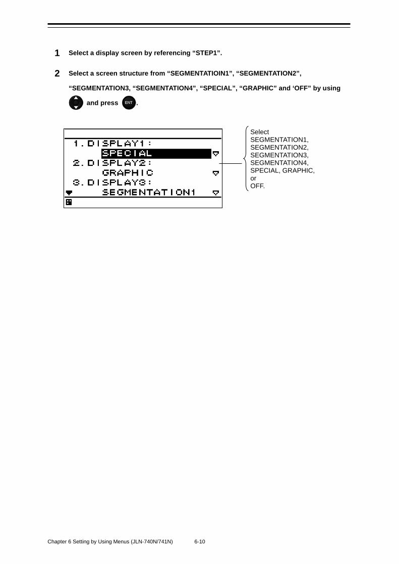
Chapter 6 Setting by Using Menus (JLN-740N/741N) 6-10
1 Select a display screen by referencing “STEP1”.
2 Select a screen structure from “SEGMENTATIOIN1”, “SEGMENTATION2”,
“SEGMENTATION3, “SEGMENTATION4”, “SPECIAL”, “GRAPHIC” and ‘OFF” by using
and press .
Select SEGMENTATION1, SEGMENTATION2, SEGMENTATION3, SEGMENTATION4, SPECIAL, GRAPHIC, or OFF.
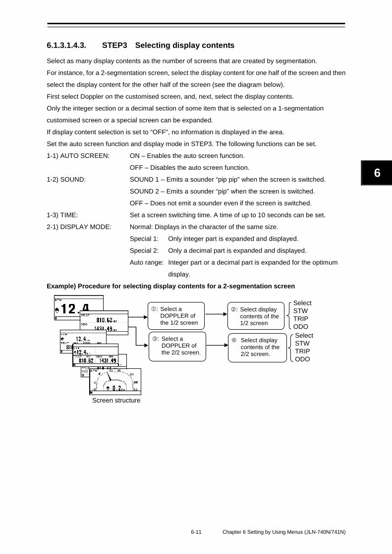
6-11 Chapter 6 Setting by Using Menus (JLN-740N/741N)
6
6.1.3.1.4.3. STEP3 Selecting display contents
Select as many display contents as the number of screens that are created by segmentation.
For instance, for a 2-segmentation screen, select the display content for one half of the screen and then
select the display content for the other half of the screen (see the diagram below).
First select Doppler on the customised screen, and, next, select the display contents.
Only the integer section or a decimal section of some item that is selected on a 1-segmentation
customised screen or a special screen can be expanded.
If display content selection is set to “OFF”, no information is displayed in the area.
Set the auto screen function and display mode in STEP3. The following functions can be set.
1-1) AUTO SCREEN: ON – Enables the auto screen function.
OFF – Disables the auto screen function.
1-2) SOUND: SOUND 1 – Emits a sounder “pip pip” when the screen is switched.
SOUND 2 – Emits a sounder “pip” when the screen is switched.
OFF – Does not emit a sounder even if the screen is switched.
1-3) TIME: Set a screen switching time. A time of up to 10 seconds can be set.
2-1) DISPLAY MODE: Normal: Displays in the character of the same size.
Special 1: Only integer part is expanded and displayed.
Special 2: Only a decimal part is expanded and displayed.
Auto range: Integer part or a decimal part is expanded for the optimum
display.
Example) Procedure for selecting display contents for a 2-segmentation screen
: Select display contents of the 1/2 screen
Select display contents of the 2/2 screen.
: Select a DOPPLER of the 1/2 screen
: Select a DOPPLER of the 2/2 screen.
Select STW TRIP ODO Select STW TRIP ODO
Screen structure
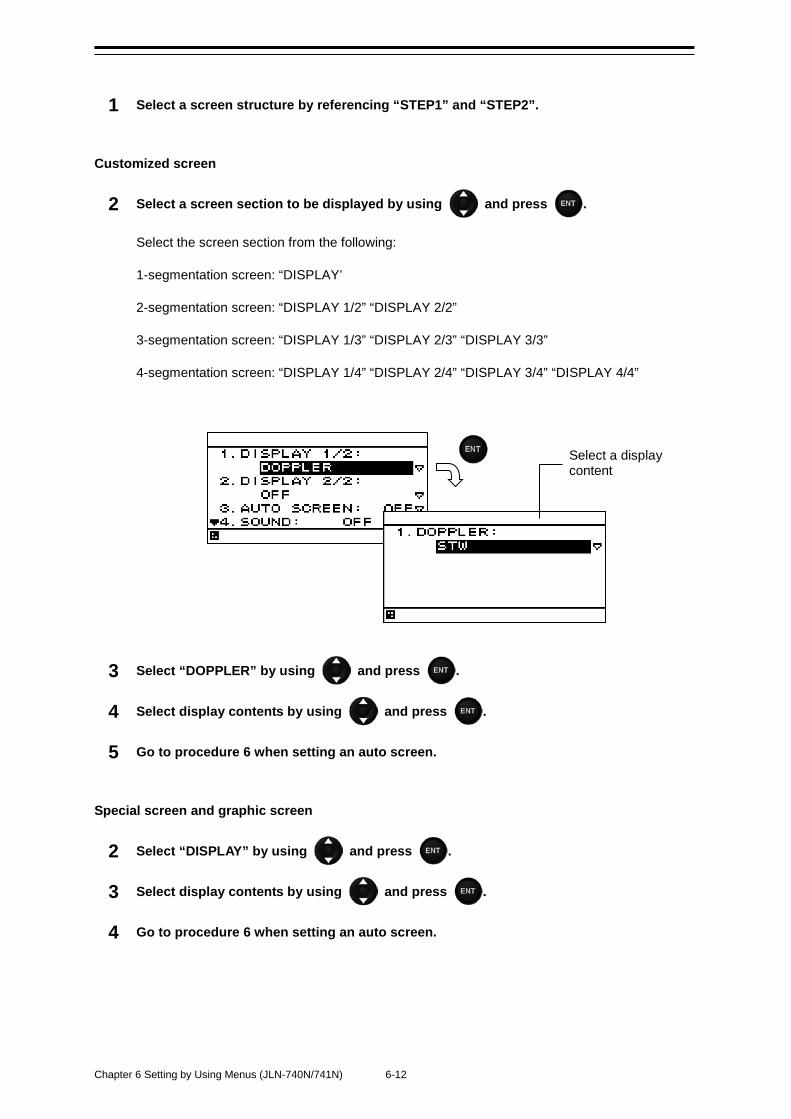
Chapter 6 Setting by Using Menus (JLN-740N/741N) 6-12
1 Select a screen structure by referencing “STEP1” and “STEP2”.
Customized screen
2 Select a screen section to be displayed by using and press .
Select the screen section from the following:
1-segmentation screen: “DISPLAY’
2-segmentation screen: “DISPLAY 1/2” “DISPLAY 2/2”
3-segmentation screen: “DISPLAY 1/3” “DISPLAY 2/3” “DISPLAY 3/3”
4-segmentation screen: “DISPLAY 1/4” “DISPLAY 2/4” “DISPLAY 3/4” “DISPLAY 4/4”
3 Select “DOPPLER” by using and press .
4 Select display contents by using and press .
5 Go to procedure 6 when setting an auto screen.
Special screen and graphic screen
2 Select “DISPLAY” by using and press .
3 Select display contents by using and press .
4 Go to procedure 6 when setting an auto screen.
Select a display content
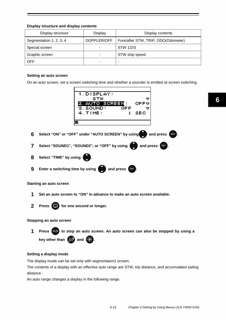
6-13 Chapter 6 Setting by Using Menus (JLN-740N/741N)
6
Display structure and display contents
Display structure Display Display contents
Segmentation 1, 2, 3, 4 DOPPLER/OFF Fore/after STW, TRIP, ODO(Odometer)
Special screen - STW 1/2/3
Graphic screen - STW ship speed
OFF - -
Setting an auto screen
On an auto screen, set a screen switching time and whether a sounder is emitted at screen switching.
6 Select “ON” or “OFF” under “AUTO SCREEN” by using and press .
7 Select “SOUND1”, “SOUND2”, or “OFF” by using and press .
8 Select “TIME” by using .
9 Enter a switching time by using and press .
Starting an auto screen
1 Set an auto screen to “ON” in advance to make an auto screen available.
2 Press for one second or longer.
Stopping an auto screen
1 Press to stop an auto screen. An auto screen can also be stopped by using a
key other than and .
Setting a display mode
The display mode can be set only with segmentaion1 screen. The contents of a display with an effective auto range are STW, trip distance, and accumulated sailing distance . An auto range changes a display in the following range.
1
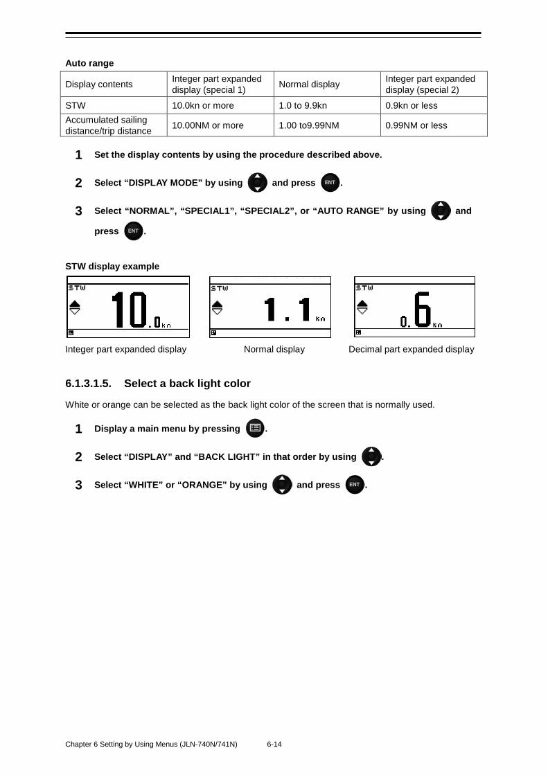
Chapter 6 Setting by Using Menus (JLN-740N/741N) 6-14
Auto range
Display contents Integer part expanded display (special 1) Normal display Integer part expanded
display (special 2)
STW 10.0kn or more 1.0 to 9.9kn 0.9kn or less Accumulated sailing distance/trip distance 10.00NM or more 1.00 to9.99NM 0.99NM or less
1 Set the display contents by using the procedure described above.
2 Select “DISPLAY MODE” by using and press .
3 Select “NORMAL”, “SPECIAL1”, “SPECIAL2”, or “AUTO RANGE” by using and
press .
STW display example
Integer part expanded display Normal display Decimal part expanded display
6.1.3.1.5. Select a back light color
White or orange can be selected as the back light color of the screen that is normally used.
1 Display a main menu by pressing .
2 Select “DISPLAY” and “BACK LIGHT” in that order by using .
3 Select “WHITE” or “ORANGE” by using and press .
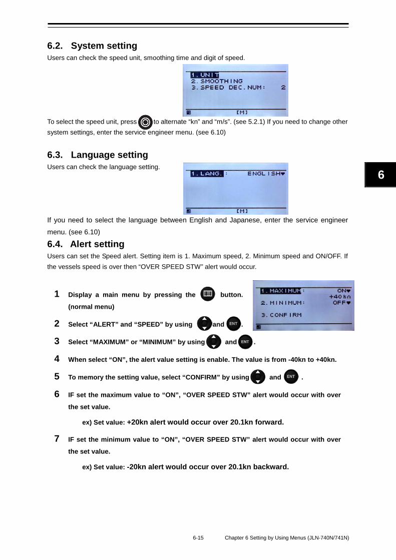
6-15 Chapter 6 Setting by Using Menus (JLN-740N/741N)
6
6.2. System setting Users can check the speed unit, smoothing time and digit of speed. To select the speed unit, press to alternate “kn” and “m/s”. (see 5.2.1) If you need to change other system settings, enter the service engineer menu. (see 6.10)
6.3. Language setting Users can check the language setting. If you need to select the language between English and Japanese, enter the service engineer menu. (see 6.10)
6.4. Alert setting Users can set the Speed alert. Setting item is 1. Maximum speed, 2. Minimum speed and ON/OFF. If the vessels speed is over then “OVER SPEED STW” alert would occur.
1 Display a main menu by pressing the button.
(normal menu)
2 Select “ALERT” and “SPEED” by using and .
3 Select “MAXIMUM” or “MINIMUM” by using and .
4 When select “ON”, the alert value setting is enable. The value is from -40kn to +40kn.
5 To memory the setting value, select “CONFIRM” by using and .
6 IF set the maximum value to “ON”, “OVER SPEED STW” alert would occur with over
the set value.
ex) Set value: +20kn alert would occur over 20.1kn forward.
7 IF set the minimum value to “ON”, “OVER SPEED STW” alert would occur with over
the set value.
ex) Set value: -20kn alert would occur over 20.1kn backward.
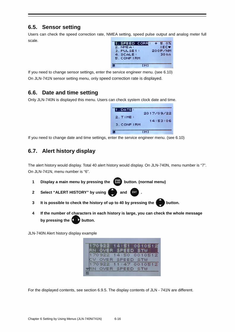
Chapter 6 Setting by Using Menus (JLN-740N/741N) 6-16
6.5. Sensor setting Users can check the speed correction rate, NMEA setting, speed pulse output and analog meter full scale. If you need to change sensor settings, enter the service engineer menu. (see 6.10) On JLN-741N sensor setting menu, only speed correction rate is displayed.
6.6. Date and time setting Only JLN-740N is displayed this menu. Users can check system clock date and time. If you need to change date and time settings, enter the service engineer menu. (see 6.10)
6.7. Alert history display The alert history would display. Total 40 alert history would display. On JLN-740N, menu number is “7”. On JLN-741N, menu number is “6”.
1 Display a main menu by pressing the button. (normal menu)
2 Select “ALERT HISTORY” by using and .
3 It is possible to check the history of up to 40 by pressing the button.
4 If the number of characters in each history is large, you can check the whole message
by pressing the button. JLN-740N Alert history display example
For the displayed contents, see section 6.9.5. The display contents of JLN - 741N are different.
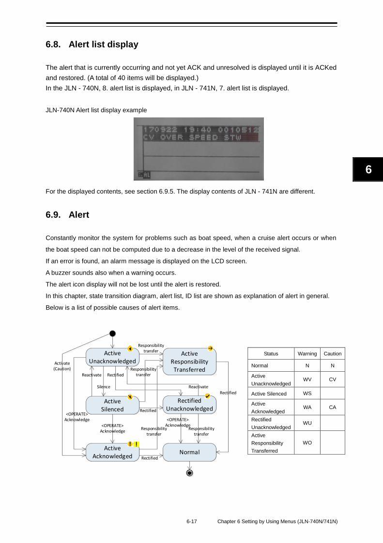
6-17 Chapter 6 Setting by Using Menus (JLN-740N/741N)
6
ActiveUnacknowledged
ActiveSilenced
ActiveAcknowledged Normal
RectifiedUnacknowledged
ActiveResponsibility Transferred
Activate(Caution)
Silence
<OPERATE>Acknowledge
<OPERATE>Acknowledge
Responsibilitytransfer
Responsibilitytransfer
Responsibilitytransfer
Rectified
Responsibilitytransfer
<OPERATE>Acknowledge
Rectified
Rectified
Reactivate
Reactivate
Rectified
6.8. Alert list display
The alert that is currently occurring and not yet ACK and unresolved is displayed until it is ACKed and restored. (A total of 40 items will be displayed.) In the JLN - 740N, 8. alert list is displayed, in JLN - 741N, 7. alert list is displayed. JLN-740N Alert list display example
For the displayed contents, see section 6.9.5. The display contents of JLN - 741N are different.
6.9. Alert
Constantly monitor the system for problems such as boat speed, when a cruise alert occurs or when
the boat speed can not be computed due to a decrease in the level of the received signal.
If an error is found, an alarm message is displayed on the LCD screen.
A buzzer sounds also when a warning occurs.
The alert icon display will not be lost until the alert is restored.
In this chapter, state transition diagram, alert list, ID list are shown as explanation of alert in general.
Below is a list of possible causes of alert items.
Status Warning Caution
Normal N N
Active Unacknowledged
WV CV
Active Silenced WS
Active Acknowledged
WA CA
Rectified Unacknowledged
WU
Active Responsibility Transferred
WO
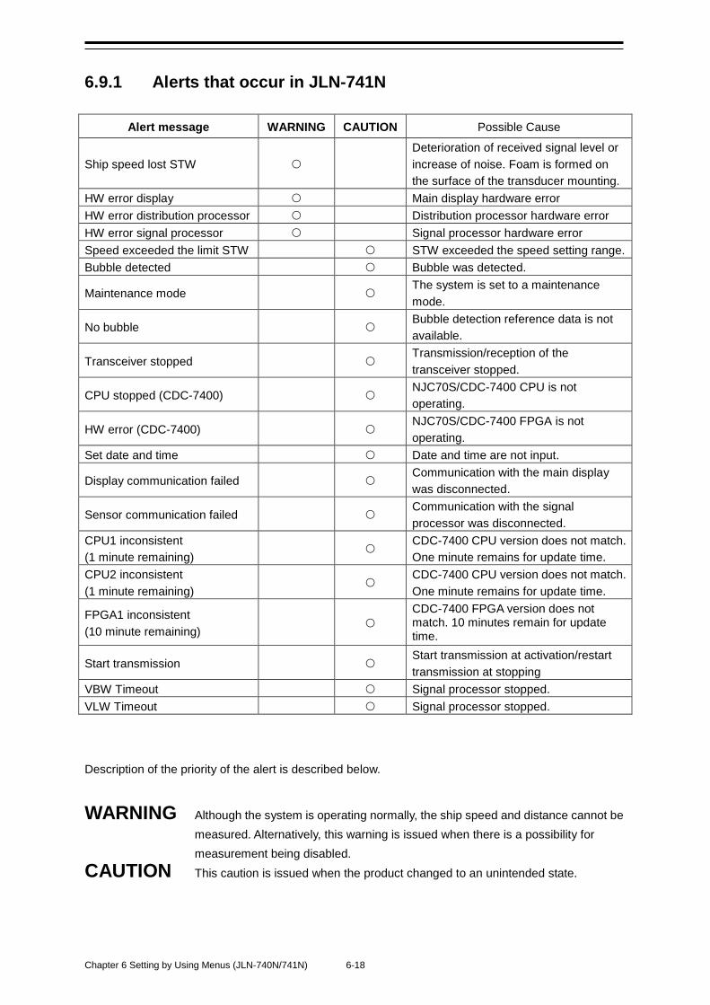
Chapter 6 Setting by Using Menus (JLN-740N/741N) 6-18
6.9.1 Alerts that occur in JLN-741N
Alert message WARNING CAUTION Possible Cause
Ship speed lost STW
Deterioration of received signal level or increase of noise. Foam is formed on the surface of the transducer mounting.
HW error display
Main display hardware error HW error distribution processor
Distribution processor hardware error
HW error signal processor
Signal processor hardware error Speed exceeded the limit STW
STW exceeded the speed setting range.
Bubble detected
Bubble was detected.
Maintenance mode
The system is set to a maintenance mode.
No bubble
Bubble detection reference data is not available.
Transceiver stopped
Transmission/reception of the transceiver stopped.
CPU stopped (CDC-7400)
NJC70S/CDC-7400 CPU is not operating.
HW error (CDC-7400)
NJC70S/CDC-7400 FPGA is not operating.
Set date and time
Date and time are not input.
Display communication failed
Communication with the main display was disconnected.
Sensor communication failed
Communication with the signal processor was disconnected.
CPU1 inconsistent (1 minute remaining)
CDC-7400 CPU version does not match. One minute remains for update time.
CPU2 inconsistent (1 minute remaining)
CDC-7400 CPU version does not match. One minute remains for update time.
FPGA1 inconsistent (10 minute remaining)
CDC-7400 FPGA version does not match. 10 minutes remain for update time.
Start transmission
Start transmission at activation/restart transmission at stopping
VBW Timeout
Signal processor stopped. VLW Timeout
Signal processor stopped.
Description of the priority of the alert is described below.
WARNING Although the system is operating normally, the ship speed and distance cannot be measured. Alternatively, this warning is issued when there is a possibility for measurement being disabled.
CAUTION This caution is issued when the product changed to an unintended state.
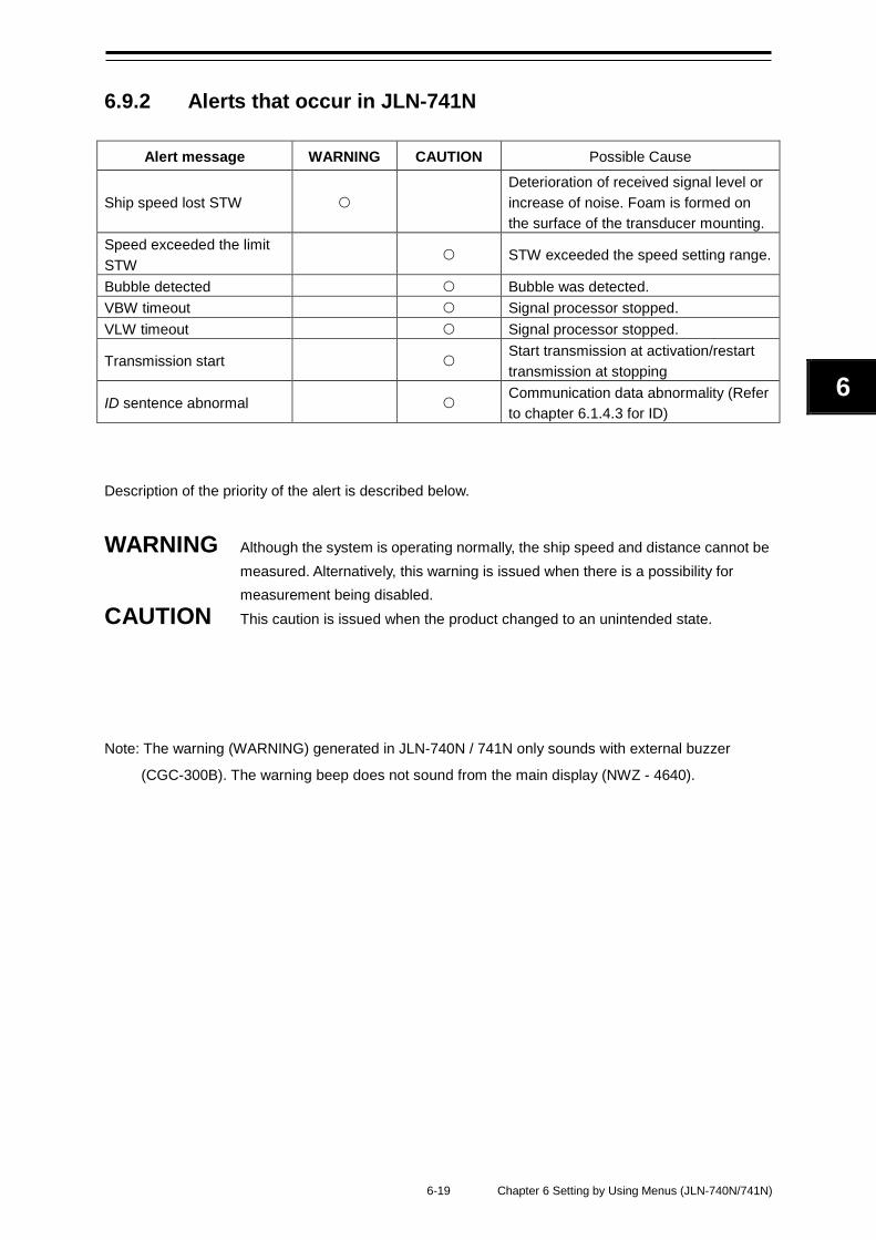
6-19 Chapter 6 Setting by Using Menus (JLN-740N/741N)
6
6.9.2 Alerts that occur in JLN-741N
Alert message WARNING CAUTION Possible Cause
Ship speed lost STW
Deterioration of received signal level or increase of noise. Foam is formed on the surface of the transducer mounting.
Speed exceeded the limit STW
STW exceeded the speed setting range.
Bubble detected
Bubble was detected. VBW timeout Signal processor stopped. VLW timeout Signal processor stopped.
Transmission start Start transmission at activation/restart transmission at stopping
ID sentence abnormal Communication data abnormality (Refer to chapter 6.1.4.3 for ID)
Description of the priority of the alert is described below.
WARNING Although the system is operating normally, the ship speed and distance cannot be measured. Alternatively, this warning is issued when there is a possibility for measurement being disabled.
CAUTION This caution is issued when the product changed to an unintended state. Note: The warning (WARNING) generated in JLN-740N / 741N only sounds with external buzzer
(CGC-300B). The warning beep does not sound from the main display (NWZ - 4640).
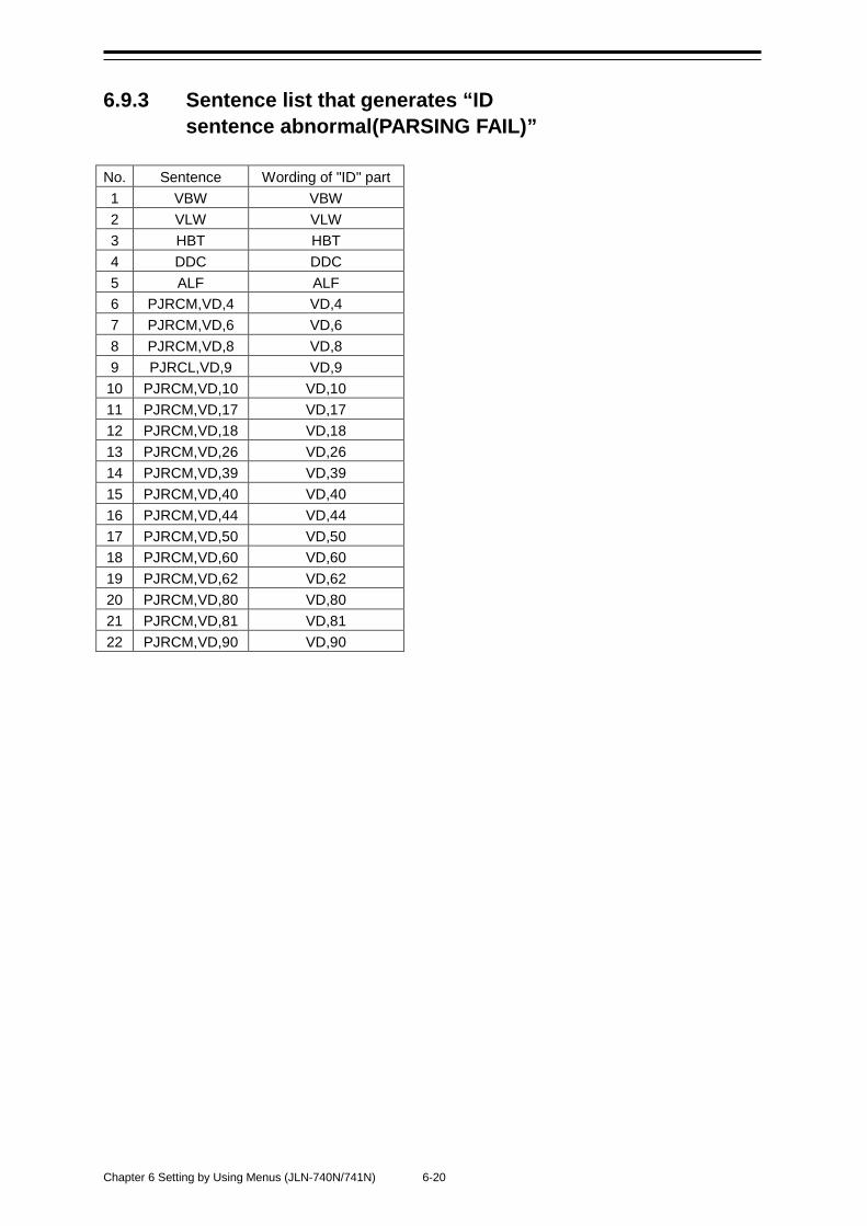
Chapter 6 Setting by Using Menus (JLN-740N/741N) 6-20
6.9.3 Sentence list that generates “ID sentence abnormal(PARSING FAIL)”
No. Sentence Wording of "ID" part 1 VBW VBW 2 VLW VLW 3 HBT HBT 4 DDC DDC 5 ALF ALF 6 PJRCM,VD,4 VD,4 7 PJRCM,VD,6 VD,6 8 PJRCM,VD,8 VD,8 9 PJRCL,VD,9 VD,9
10 PJRCM,VD,10 VD,10 11 PJRCM,VD,17 VD,17 12 PJRCM,VD,18 VD,18 13 PJRCM,VD,26 VD,26 14 PJRCM,VD,39 VD,39 15 PJRCM,VD,40 VD,40 16 PJRCM,VD,44 VD,44 17 PJRCM,VD,50 VD,50 18 PJRCM,VD,60 VD,60 19 PJRCM,VD,62 VD,62 20 PJRCM,VD,80 VD,80 21 PJRCM,VD,81 VD,81 22 PJRCM,VD,90 VD,90
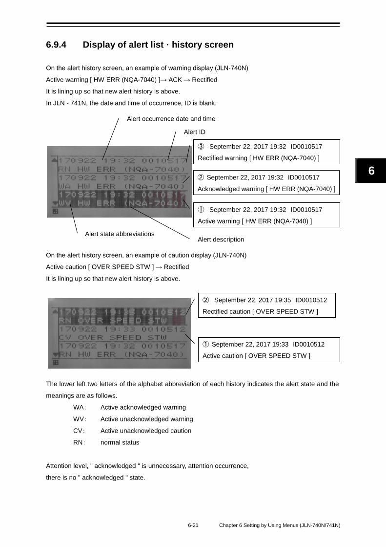
6-21 Chapter 6 Setting by Using Menus (JLN-740N/741N)
6
6.9.4 Display of alert list · history screen On the alert history screen, an example of warning display (JLN-740N)
Active warning [ HW ERR (NQA-7040) ]→ ACK → Rectified
It is lining up so that new alert history is above.
In JLN - 741N, the date and time of occurrence, ID is blank.
On the alert history screen, an example of caution display (JLN-740N)
Active caution [ OVER SPEED STW ] → Rectified
It is lining up so that new alert history is above.
The lower left two letters of the alphabet abbreviation of each history indicates the alert state and the
meanings are as follows.
WA: Active acknowledged warning
WV: Active unacknowledged warning
CV: Active unacknowledged caution
RN: normal status
Attention level, " acknowledged " is unnecessary, attention occurrence,
there is no " acknowledged " state.
① September 22, 2017 19:32 ID0010517
Active warning [ HW ERR (NQA-7040) ]
③ September 22, 2017 19:32 ID0010517
Rectified warning [ HW ERR (NQA-7040) ]
② September 22, 2017 19:32 ID0010517
Acknowledged warning [ HW ERR (NQA-7040) ]
② September 22, 2017 19:35 ID0010512
Rectified caution [ OVER SPEED STW ]
① September 22, 2017 19:33 ID0010512
Active caution [ OVER SPEED STW ]
Alert occurrence date and time
Alert ID
Alert state abbreviations Alert description
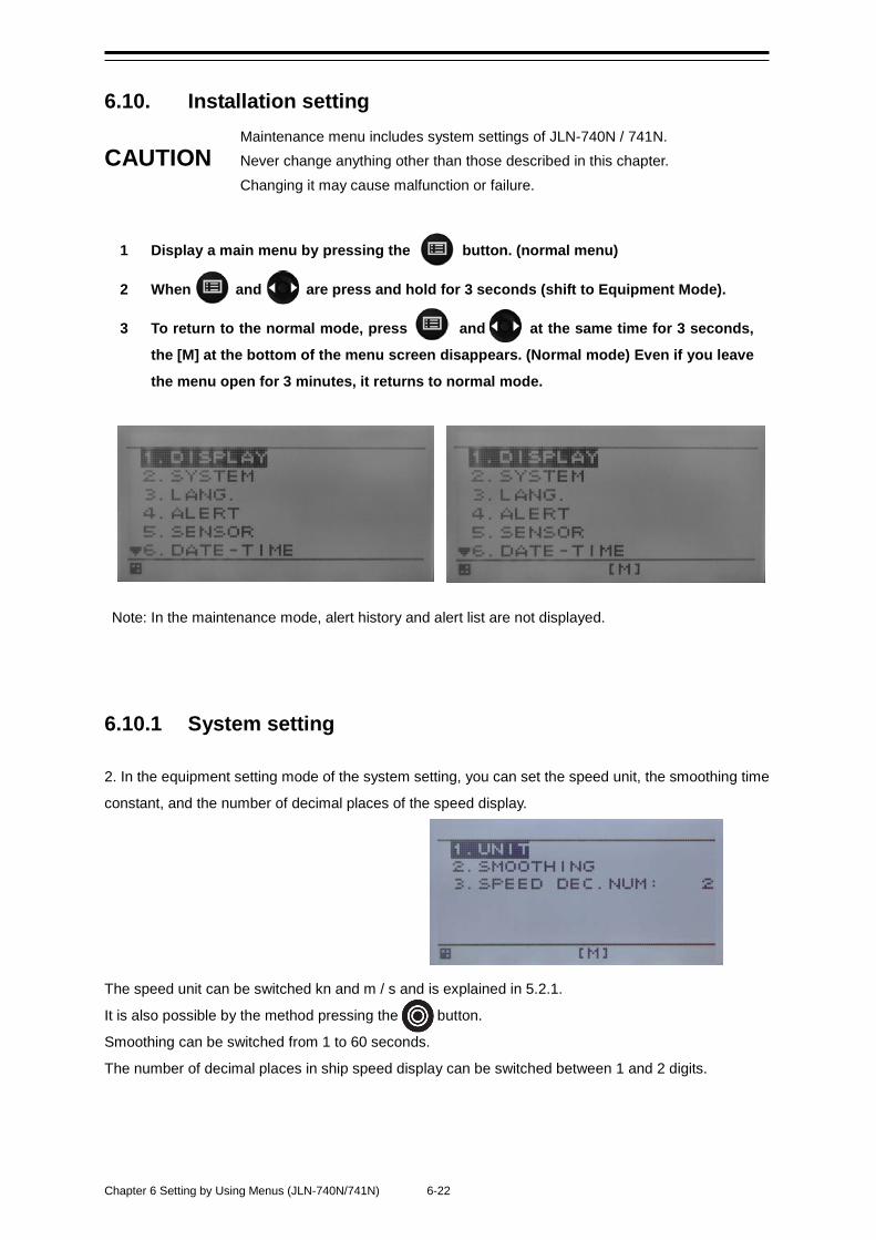
Chapter 6 Setting by Using Menus (JLN-740N/741N) 6-22
6.10. Installation setting Maintenance menu includes system settings of JLN-740N / 741N.
CAUTION Never change anything other than those described in this chapter. Changing it may cause malfunction or failure.
1 Display a main menu by pressing the button. (normal menu)
2 When and are press and hold for 3 seconds (shift to Equipment Mode).
3 To return to the normal mode, press and at the same time for 3 seconds,
the [M] at the bottom of the menu screen disappears. (Normal mode) Even if you leave
the menu open for 3 minutes, it returns to normal mode.
Note: In the maintenance mode, alert history and alert list are not displayed.
6.10.1 System setting 2. In the equipment setting mode of the system setting, you can set the speed unit, the smoothing time
constant, and the number of decimal places of the speed display.
The speed unit can be switched kn and m / s and is explained in 5.2.1.
It is also possible by the method pressing the button.
Smoothing can be switched from 1 to 60 seconds.
The number of decimal places in ship speed display can be switched between 1 and 2 digits.
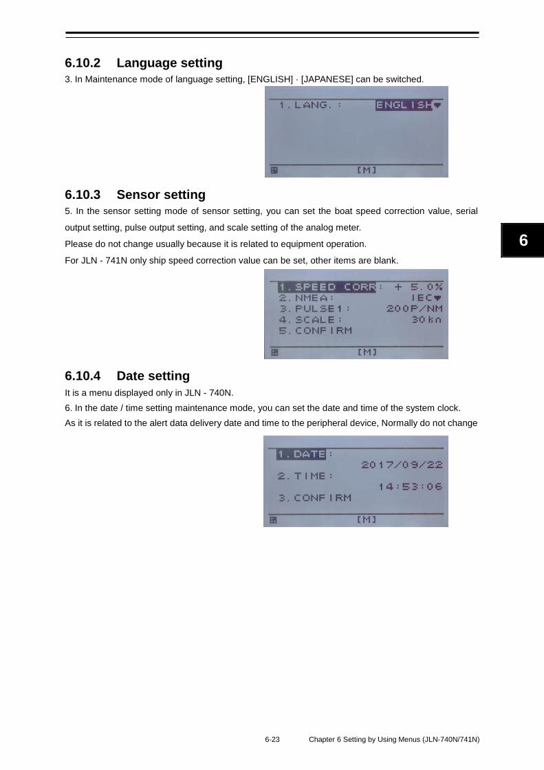
6-23 Chapter 6 Setting by Using Menus (JLN-740N/741N)
6
6.10.2 Language setting 3. In Maintenance mode of language setting, [ENGLISH] · [JAPANESE] can be switched.
6.10.3 Sensor setting 5. In the sensor setting mode of sensor setting, you can set the boat speed correction value, serial
output setting, pulse output setting, and scale setting of the analog meter.
Please do not change usually because it is related to equipment operation.
For JLN - 741N only ship speed correction value can be set, other items are blank.
6.10.4 Date setting It is a menu displayed only in JLN - 740N. 6. In the date / time setting maintenance mode, you can set the date and time of the system clock. As it is related to the alert data delivery date and time to the peripheral device, Normally do not change

Chapter 6 Setting by Using Menus (JLN-740N/741N) 6-24
(This page intentionally left blank)
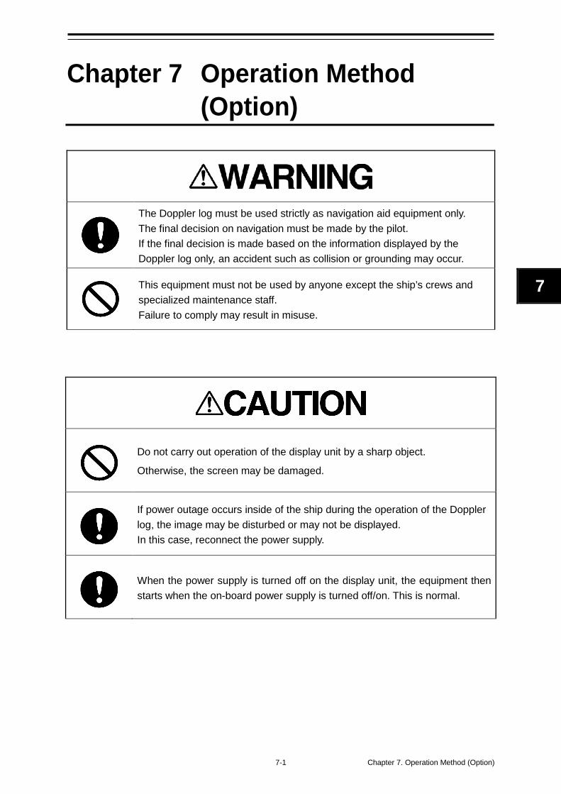
7-1 Chapter 7. Operation Method (Option)
7
Chapter 7 Operation Method (Option)
The Doppler log must be used strictly as navigation aid equipment only. The final decision on navigation must be made by the pilot. If the final decision is made based on the information displayed by the Doppler log only, an accident such as collision or grounding may occur.
This equipment must not be used by anyone except the ship’s crews and specialized maintenance staff. Failure to comply may result in misuse.
Do not carry out operation of the display unit by a sharp object.
Otherwise, the screen may be damaged.
If power outage occurs inside of the ship during the operation of the Doppler log, the image may be disturbed or may not be displayed. In this case, reconnect the power supply.
When the power supply is turned off on the display unit, the equipment then starts when the on-board power supply is turned off/on. This is normal.
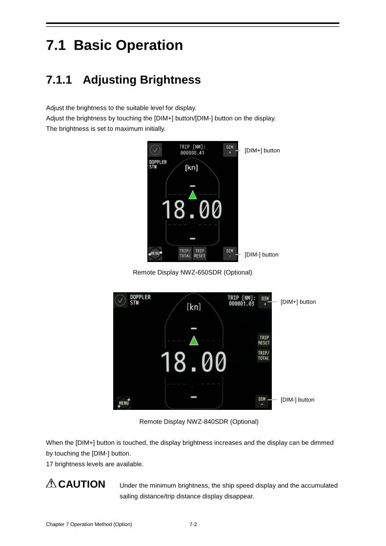
Chapter 7 Operation Method (Option) 7-2
7.1 Basic Operation
7.1.1 Adjusting Brightness Adjust the brightness to the suitable level for display. Adjust the brightness by touching the [DIM+] button/[DIM-] button on the display. The brightness is set to maximum initially.
Remote Display NWZ-650SDR (Optional)
Remote Display NWZ-840SDR (Optional) When the [DIM+] button is touched, the display brightness increases and the display can be dimmed by touching the [DIM-] button. 17 brightness levels are available.
CAUTION Under the minimum brightness, the ship speed display and the accumulated sailing distance/trip distance display disappear.
[DIM+] button
[DIM-] button
[DIM+] button
[DIM-] button
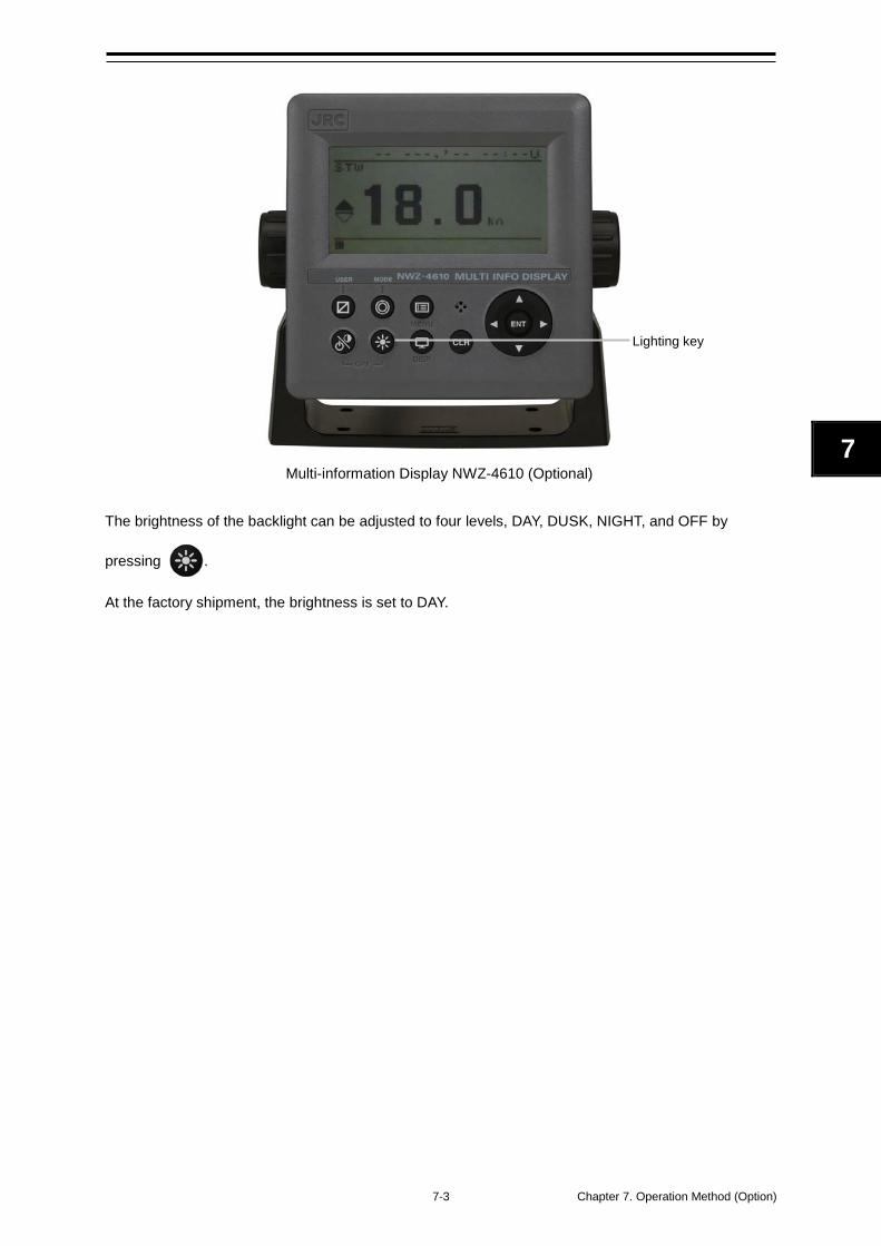
7-3 Chapter 7. Operation Method (Option)
7
Multi-information Display NWZ-4610 (Optional)
The brightness of the backlight can be adjusted to four levels, DAY, DUSK, NIGHT, and OFF by
pressing .
At the factory shipment, the brightness is set to DAY.
Lighting key
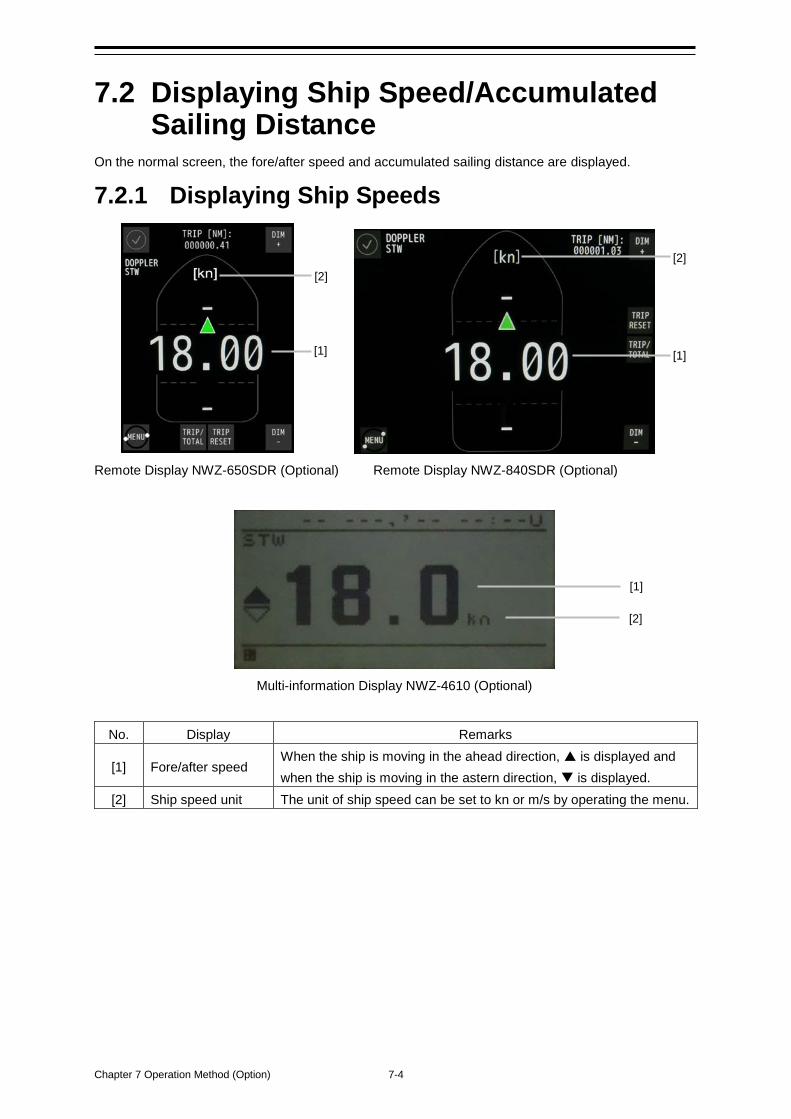
Chapter 7 Operation Method (Option) 7-4
7.2 Displaying Ship Speed/Accumulated Sailing Distance
On the normal screen, the fore/after speed and accumulated sailing distance are displayed.
7.2.1 Displaying Ship Speeds
Remote Display NWZ-650SDR (Optional) Remote Display NWZ-840SDR (Optional)
Multi-information Display NWZ-4610 (Optional)
No. Display Remarks
[1] Fore/after speed When the ship is moving in the ahead direction, is displayed and when the ship is moving in the astern direction, is displayed.
[2] Ship speed unit The unit of ship speed can be set to kn or m/s by operating the menu.
[1] [1]
[2]
[1]
[2]
[2]
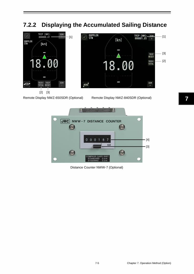
7-5 Chapter 7. Operation Method (Option)
7
7.2.2 Displaying the Accumulated Sailing Distance
Remote Display NWZ-650SDR (Optional) Remote Display NWZ-840SDR (Optional)
Distance Counter NWW-7 (Optional)
[4]
[3]
[1]
[2] [3]
[1]
[2]
[3]
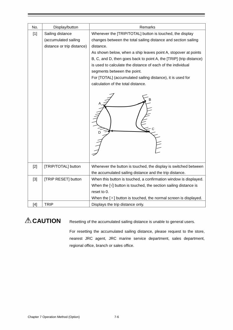
Chapter 7 Operation Method (Option) 7-6
No. Display/button Remarks [1] Sailing distance
(accumulated sailing distance or trip distance)
Whenever the [TRIP/TOTAL] button is touched, the display changes between the total sailing distance and section sailing distance. As shown below, when a ship leaves point A, stopover at points B, C, and D, then goes back to point A, the [TRIP] (trip distance) is used to calculate the distance of each of the individual segments between the point. For [TOTAL] (accumulated sailing distance), it is used for calculation of the total distance.
[2] [TRIP/TOTAL] button Whenever the button is touched, the display is switched between
the accumulated sailing distance and the trip distance. [3] [TRIP RESET] button When this button is touched, a confirmation window is displayed.
When the [√] button is touched, the section sailing distance is reset to 0. When the [] button is touched, the normal screen is displayed.
[4] TRIP Displays the trip distance only.
CAUTION Resetting of the accumulated sailing distance is unable to general users.
For resetting the accumulated sailing distance, please request to the store,
nearest JRC agent, JRC marine service department, sales department,
regional office, branch or sales office.
A B
C D
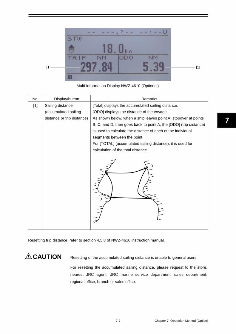
7-7 Chapter 7. Operation Method (Option)
7
Multi-information Display NWZ-4610 (Optional)
No. Display/button Remarks [1] Sailing distance
(accumulated sailing distance or trip distance)
[Total] displays the accumulated sailing distance. [ODO] displays the distance of the voyage. As shown below, when a ship leaves point A, stopover at points B, C, and D, then goes back to point A, the [ODO] (trip distance) is used to calculate the distance of each of the individual segments between the point. For [TOTAL] (accumulated sailing distance), it is used for calculation of the total distance.
Resetting trip distance, refer to section 4.5.8 of NWZ-4610 instruction manual.
CAUTION Resetting of the accumulated sailing distance is unable to general users.
For resetting the accumulated sailing distance, please request to the store,
nearest JRC agent, JRC marine service department, sales department,
regional office, branch or sales office.
A B
C D
[1] [1]
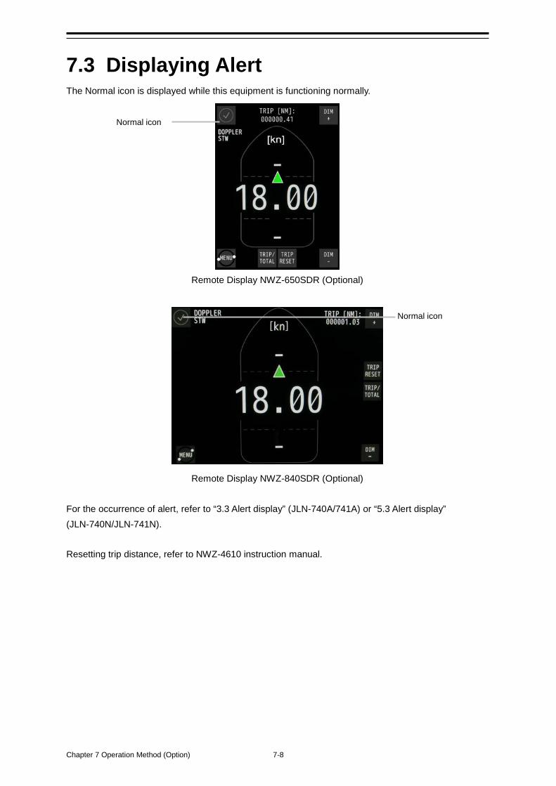
Chapter 7 Operation Method (Option) 7-8
7.3 Displaying Alert The Normal icon is displayed while this equipment is functioning normally.
Remote Display NWZ-650SDR (Optional)
Remote Display NWZ-840SDR (Optional) For the occurrence of alert, refer to “3.3 Alert display” (JLN-740A/741A) or “5.3 Alert display” (JLN-740N/JLN-741N). Resetting trip distance, refer to NWZ-4610 instruction manual.
Normal icon
Normal icon
8-1 Chapter 8 Setting by Using Menus (Option)
8
Chapter 8 Setting by Using Menus (Option)
In NWZ-650SDR/840SDR, various settings and adjustments can be performed by using the menus that are displayed. On NWZ-4610, various configurations can be set and adjusted by pressing the buttons.
Adjustments must be made by specialized service technicians. Incorrect settings may result in unstable operation, and this may lead to accidents or equipment failure.
Adjust the brightness of main display according to the surrounding lighting. In NWZ-650SDR/840SDR, the setting of [NIGHT] may interfere with the recognition of display information. In NWZ-4610, the setting of [MINIMUM] may interfere with the recognition of display information.
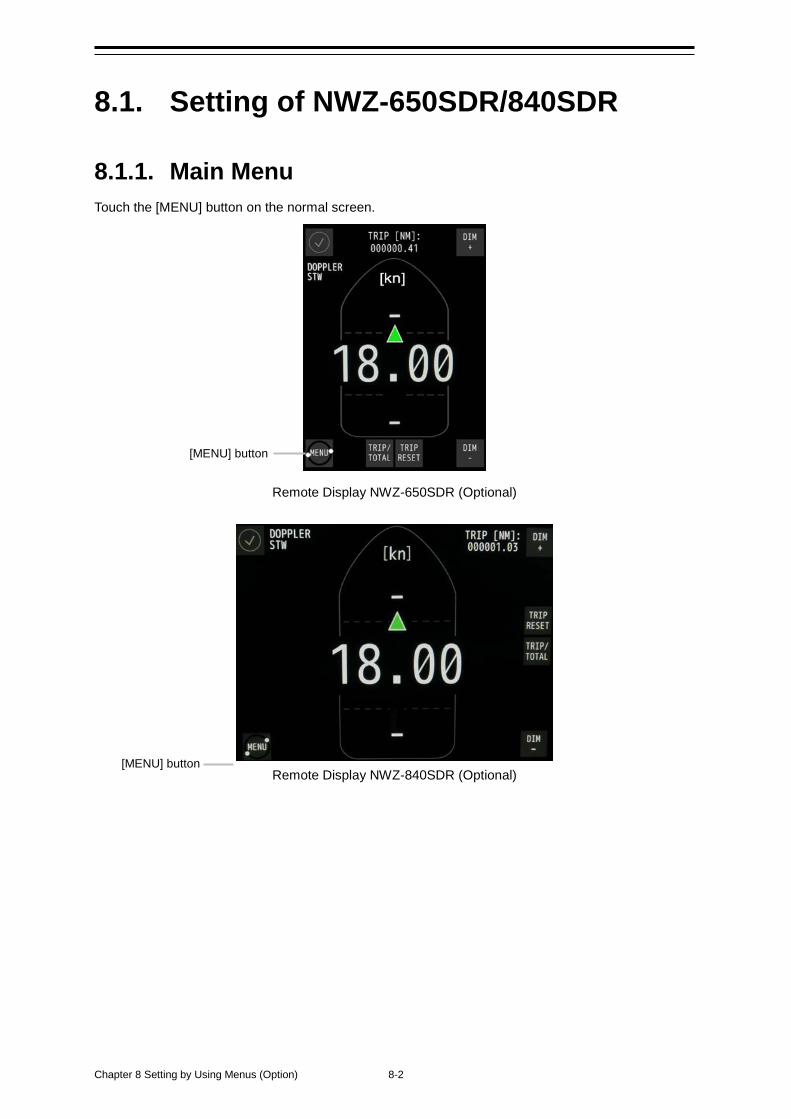
Chapter 8 Setting by Using Menus (Option) 8-2
8.1. Setting of NWZ-650SDR/840SDR
8.1.1. Main Menu Touch the [MENU] button on the normal screen.
Remote Display NWZ-650SDR (Optional)
Remote Display NWZ-840SDR (Optional)
[MENU] button
[MENU] button
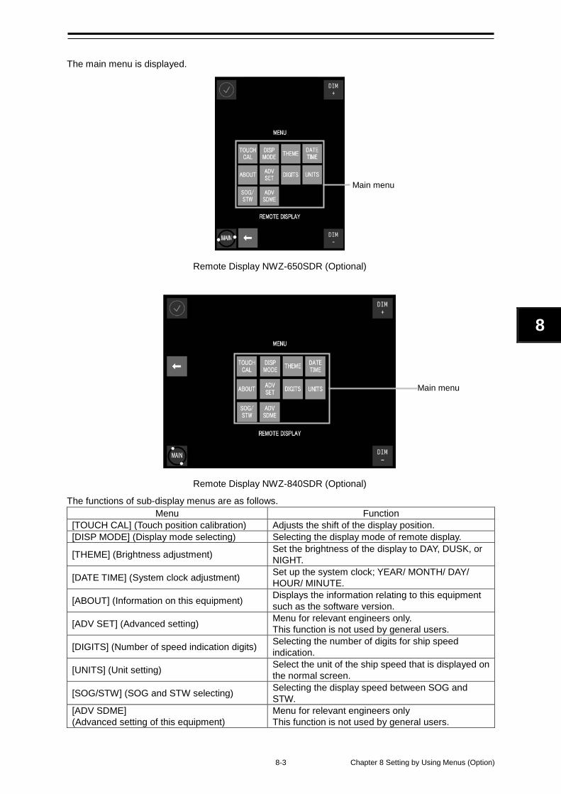
8-3 Chapter 8 Setting by Using Menus (Option)
8
The main menu is displayed.
Remote Display NWZ-650SDR (Optional)
Remote Display NWZ-840SDR (Optional)
The functions of sub-display menus are as follows. Menu Function
[TOUCH CAL] (Touch position calibration) Adjusts the shift of the display position. [DISP MODE] (Display mode selecting) Selecting the display mode of remote display.
[THEME] (Brightness adjustment) Set the brightness of the display to DAY, DUSK, or NIGHT.
[DATE TIME] (System clock adjustment) Set up the system clock; YEAR/ MONTH/ DAY/ HOUR/ MINUTE.
[ABOUT] (Information on this equipment) Displays the information relating to this equipment such as the software version.
[ADV SET] (Advanced setting) Menu for relevant engineers only. This function is not used by general users.
[DIGITS] (Number of speed indication digits) Selecting the number of digits for ship speed indication.
[UNITS] (Unit setting) Select the unit of the ship speed that is displayed on the normal screen.
[SOG/STW] (SOG and STW selecting) Selecting the display speed between SOG and STW.
[ADV SDME] (Advanced setting of this equipment)
Menu for relevant engineers only This function is not used by general users.
Main menu
Main menu
Chapter 8 Setting by Using Menus (Option) 8-4
8.1.2. Operation of Each Menu
8.1.2.1. Touch Position Calibration When the touched position and the intended button do not match when the screen is touched, adjust the touched position in this menu.
1 Touch the [TOUCH CAL] button in the main menu. A touch position calibration confirmation screen is displayed.
2 Touch [CONFIRM CALIBRATE THE TOUCH SCREEN]. The start screen is displayed. 5 seconds later, a touch position calibration screen is displayed.
3 Touch the center of the target marks at the four corners of the screen. Touch the center of the target marks at the four corners in the order from 1 to 4. The following screen is displayed.
4 Touch the screen for confirmation.
5 When is displayed at the position that was touched: The adjustment is completed. Close the [TOUCH CAL] menu by touching the [ACCEPT] button. When the touched position and the position of do not match: Perform the adjustment again. Touch the [AGAIN] button and restart from Step 2.
CAUTION If the calibration takes about one minute or more, the “DISPLAY COMM FAIL” alert may occur upon returning to the normal screen. This is not the system malfunction.
8-5 Chapter 8 Setting by Using Menus (Option)
8
8.1.2.2. Brightness Adjustment The brightness of the screen can be adjusted by the time period of a day.
1 Touch the [THEME] button in the main menu. A brightness adjustment screen is displayed.
2 Change the brightness by touching the [-]/[+] buttons. DAY: High brightness (for daytime) (initial value) DUSK: Medium brightness (for evening time) NIGHT: Low brightness (for night time)
3 Touch button to apply and close the [THEME] menu.
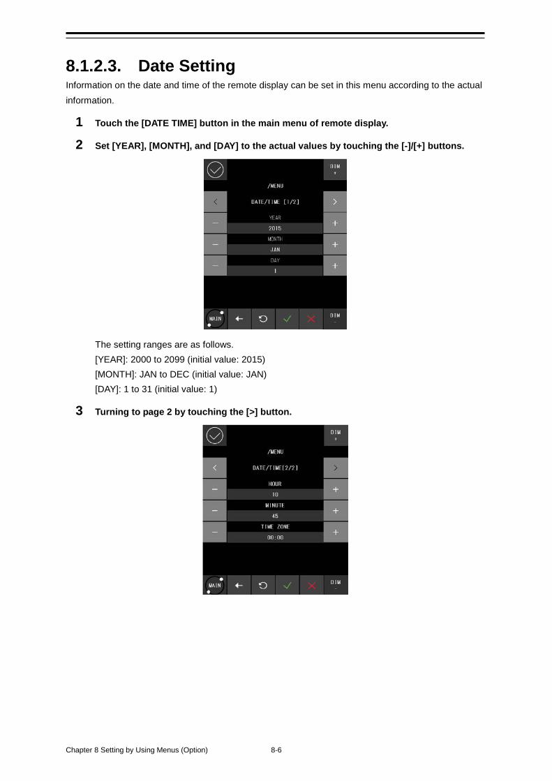
Chapter 8 Setting by Using Menus (Option) 8-6
8.1.2.3. Date Setting Information on the date and time of the remote display can be set in this menu according to the actual information.
1 Touch the [DATE TIME] button in the main menu of remote display.
2 Set [YEAR], [MONTH], and [DAY] to the actual values by touching the [-]/[+] buttons.
The setting ranges are as follows. [YEAR]: 2000 to 2099 (initial value: 2015) [MONTH]: JAN to DEC (initial value: JAN) [DAY]: 1 to 31 (initial value: 1)
3 Turning to page 2 by touching the [>] button.
8-7 Chapter 8 Setting by Using Menus (Option)
8
4. Set [HOUR], [MINUTE] and [TIME ZONE] to the actual values by touching the [-]/[+] buttons. The setting ranges are as follows. [HOUR]: 0 to 23 (initial value: 0) [MINUTE]: 0 to 59 (initial value: 0) [TIME ZONE]: -12:00 to +12:00 (initial value: 00:00)
5. Confirm the setting and close the [DATE TIME] menu by touching the button.
Chapter 8 Setting by Using Menus (Option) 8-8
8.1.2.4. Confirming the system information The information relating to this equipment such as software version can be displayed. Before making an enquiry on this equipment, check the information of this equipment in the [ABOUT] menu.
1 Touch the [ABOUT] button in the main menu. Information on the equipment is displayed.
2 Close the [ABOUT] menu by touching the button. Information that is displayed in the [ABOUT] menu. The following information is displayed in the [ABOUT] menu.
Information Description
MF ver. : Software version of remote display. Latest software version at the time of print: V1.026
MF ser. : Serial version of distributed processor.
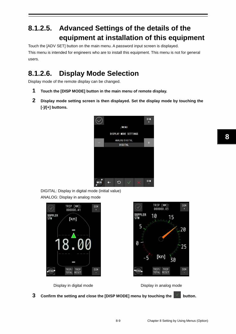
8-9 Chapter 8 Setting by Using Menus (Option)
8
8.1.2.5. Advanced Settings of the details of the equipment at installation of this equipment
Touch the [ADV SET] button on the main menu. A password input screen is displayed. This menu is intended for engineers who are to install this equipment. This menu is not for general users.
8.1.2.6. Display Mode Selection Display mode of the remote display can be changed.
1 Touch the [DISP MODE] button in the main menu of remote display.
2 Display mode setting screen is then displayed. Set the display mode by touching the [-]/[+] buttons.
DIGITAL: Display in digital mode (initial value) ANALOG: Display in analog mode
Display in digital mode Display in analog mode
3 Confirm the setting and close the [DISP MODE] menu by touching the button.
Chapter 8 Setting by Using Menus (Option) 8-10
8.1.2.7. Ship Speed Unit Settings The unit of the ship speed that is displayed on the normal screen can be set.
1 Touch the [UNITS] button in the main menu. A screen for setting a unit is displayed.
2 Change the unit by touching the [-]/[+] buttons. kn: knot (initial value) m/s: meter per second
3 Close the [UNITS] menu by touching the button.
8-11 Chapter 8 Setting by Using Menus (Option)
8
8.1.2.8. Advanced SDME Settings Touch the [ADV SDME] button on the main menu. A password input screen is displayed. This menu is intended for engineers who are to install this equipment. This menu is not for general users.
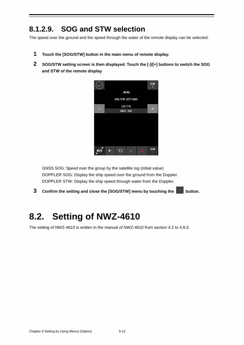
Chapter 8 Setting by Using Menus (Option) 8-12
8.1.2.9. SOG and STW selection The speed over the ground and the speed through the water of the remote display can be selected.
1 Touch the [SOG/STW] button in the main menu of remote display.
2 SOG/STW setting screen is then displayed. Touch the [-]/[+] buttons to switch the SOG and STW of the remote display
GNSS SOG: Speed over the group by the satellite log (initial value) DOPPLER SOG: Display the ship speed over the ground from the Doppler. DOPPLER STW: Display the ship speed through water from the Doppler.
3 Confirm the setting and close the [SOG/STW] menu by touching the button.
8.2. Setting of NWZ-4610 The setting of NWZ-4610 is written in the manual of NWZ-4610 from section 4.2 to 4.8.5.
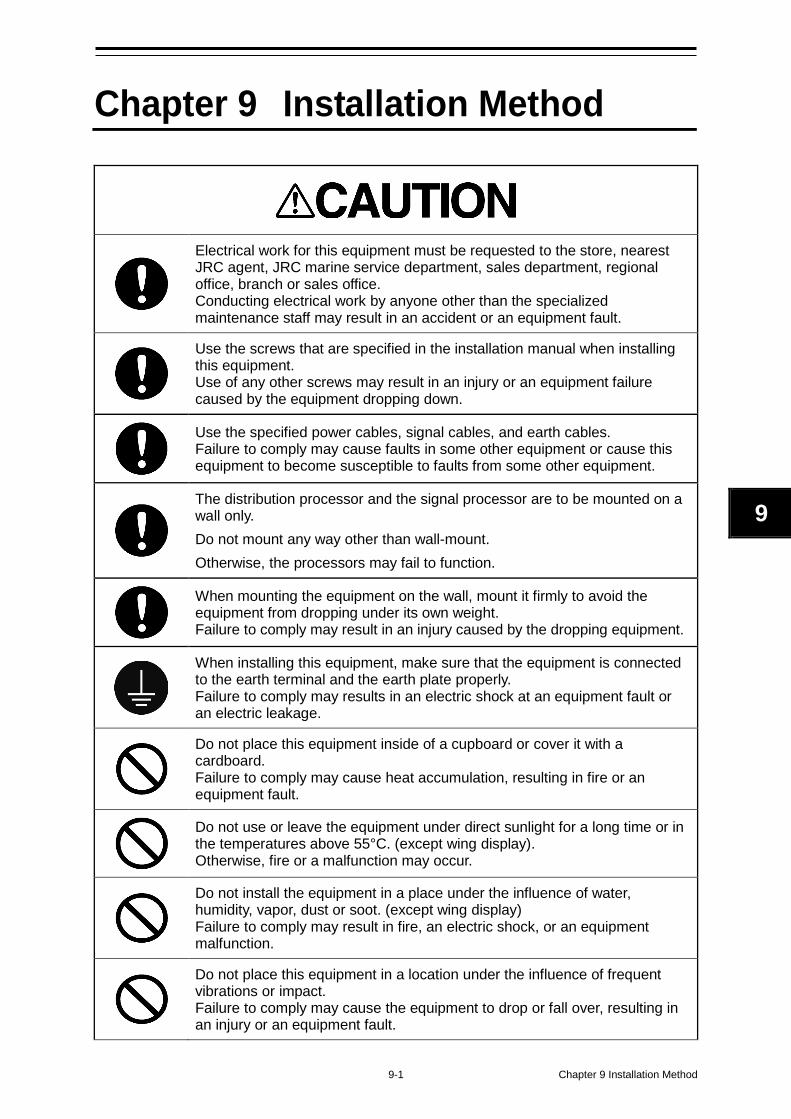
9-1 Chapter 9 Installation Method
9
Chapter 9 Installation Method
Electrical work for this equipment must be requested to the store, nearest JRC agent, JRC marine service department, sales department, regional office, branch or sales office. Conducting electrical work by anyone other than the specialized maintenance staff may result in an accident or an equipment fault.
Use the screws that are specified in the installation manual when installing this equipment. Use of any other screws may result in an injury or an equipment failure caused by the equipment dropping down.
Use the specified power cables, signal cables, and earth cables. Failure to comply may cause faults in some other equipment or cause this equipment to become susceptible to faults from some other equipment.
The distribution processor and the signal processor are to be mounted on a wall only. Do not mount any way other than wall-mount. Otherwise, the processors may fail to function.
When mounting the equipment on the wall, mount it firmly to avoid the equipment from dropping under its own weight. Failure to comply may result in an injury caused by the dropping equipment.
When installing this equipment, make sure that the equipment is connected to the earth terminal and the earth plate properly. Failure to comply may results in an electric shock at an equipment fault or an electric leakage.
Do not place this equipment inside of a cupboard or cover it with a cardboard. Failure to comply may cause heat accumulation, resulting in fire or an equipment fault.
Do not use or leave the equipment under direct sunlight for a long time or in the temperatures above 55°C. (except wing display). Otherwise, fire or a malfunction may occur.
Do not install the equipment in a place under the influence of water, humidity, vapor, dust or soot. (except wing display) Failure to comply may result in fire, an electric shock, or an equipment malfunction.
Do not place this equipment in a location under the influence of frequent vibrations or impact. Failure to comply may cause the equipment to drop or fall over, resulting in an injury or an equipment fault.
Chapter 9 Installation Method 9-2
9.1 Installation of the Main Display and Distribution Processor
Installation location Install these equipment units in a place that is not susceptible to interferences since signal cables are susceptible to noise and generate noise easily. Do not install the equipment units parallel to the cable of the DSB radio or amateur radio device. Do not install the equipment units in a place that is exposed to direct sunlight (except wing displays), wave splashes, or hot air.
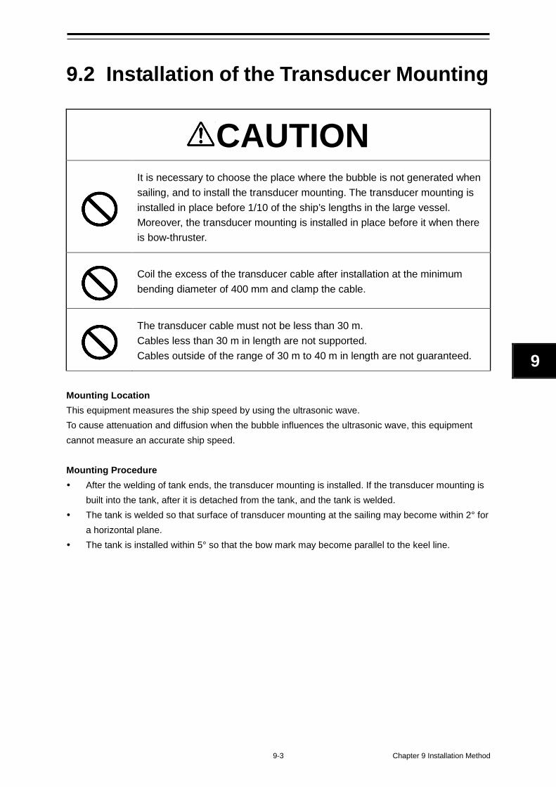
9-3 Chapter 9 Installation Method
9
9.2 Installation of the Transducer Mounting
CAUTION
It is necessary to choose the place where the bubble is not generated when sailing, and to install the transducer mounting. The transducer mounting is installed in place before 1/10 of the ship’s lengths in the large vessel. Moreover, the transducer mounting is installed in place before it when there is bow-thruster.
Coil the excess of the transducer cable after installation at the minimum bending diameter of 400 mm and clamp the cable.
The transducer cable must not be less than 30 m. Cables less than 30 m in length are not supported. Cables outside of the range of 30 m to 40 m in length are not guaranteed.
Mounting Location This equipment measures the ship speed by using the ultrasonic wave. To cause attenuation and diffusion when the bubble influences the ultrasonic wave, this equipment cannot measure an accurate ship speed. Mounting Procedure After the welding of tank ends, the transducer mounting is installed. If the transducer mounting is
built into the tank, after it is detached from the tank, and the tank is welded. The tank is welded so that surface of transducer mounting at the sailing may become within 2° for
a horizontal plane. The tank is installed within 5° so that the bow mark may become parallel to the keel line.
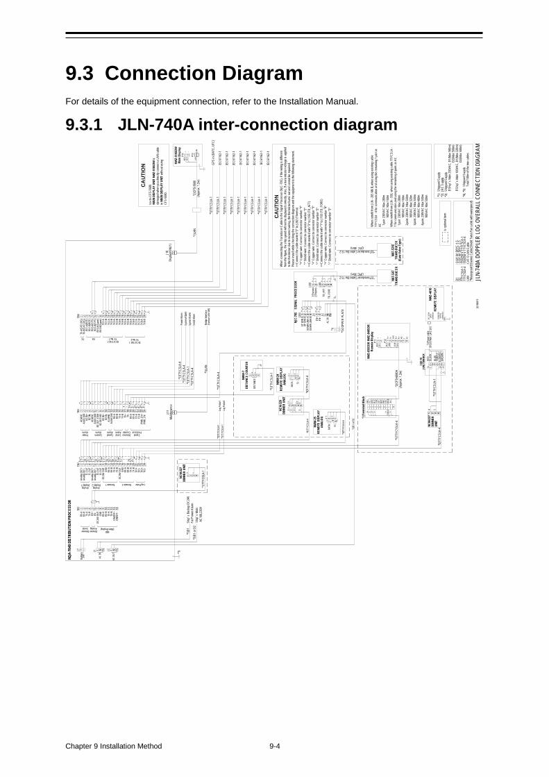
Chapter 9 Installation Method 9-4
9.3 Connection Diagram For details of the equipment connection, refer to the Installation Manual.
9.3.1 JLN-740A inter-connection diagram
*1
)TTY
CSLA
-1
*1)T
TYCS
LA-1
*1)T
TYCS
LA-1
IEC6
1162
-1
IEC6
1162
-1
IEC6
1162
-1
NQA-
7040
DIS
TRIB
UTIO
N PR
OCES
SOR
IEC6
1162
-1*1
)TTY
CSLA
-1
J10
Disp
lay(O
NLY)
J11
Maint
enan
ce
J7Ba
ttery
24
V+ - J1
AC IN
L N FG
*1)D
1Sh
ip’s B
acku
p DC2
4VFo
r Pow
er Al
arm
*3)D
1 or
D2
Ship’
s Main
A
C100
,230V1 2 3 4 5 6 7 8 9 10 11 12 13 14TB
1
DimmerSerial
DimmerAnalog
MID(Main Display)
RX-A
RX-B
TX-A
TX-B
RX+
RX-
DC26
V OU
TGN
DRX
-ARX
-BTX
-ATX
-BON
/OFF
+ON
/OFF
-
1 2 3 4 5 6 7 8 9 10 11 12 13 14 15 16 17 18 19 20 21 22 23 24TB2
Analo
g OU
T+An
alog
OUT-
EL O
UTEL
OUT
Analo
g OU
T+An
alog
OUT-
EL O
UTEL
OUT
DC26
V OU
TGN
DRX
-ARX
-BTX
-ATX
-BDC
26V
OUT
GND
RX-A
RX-B
TX-A
TX-B
TX1+
TX1-
TX2+
TX2-
Remote 1Analog
Display 1
NWW
-24
REMO
TE D
ISPL
AYAN
ALOG 1 1 2 2
DATA EL
1 L
*4)T
TYCS
LA-4
NCM-
329
DIMM
ER U
NIT
1 1 2 2
1 1 2 2
*4)T
TYCS
LA-4
NWW
-7DI
STAN
CE C
OUNT
ER
DIST
ANCE
1 2 3 4
+
*1)T
TYCS
LA-1
IEC6
1162
-1*1
)TTY
CSLA
-1
IEC6
1162
-1*1
)TTY
CSLA
-1
IEC6
1162
-1*1
)TTY
CSLA
-1
IEC6
1162
-1*1
)TTY
CSLA
-1
*1)T
TYCS
LA-4
*1)T
TYCS
LA-4
*1)T
TYCS
LA-4
*1)T
TYCS
LA-1
*1)T
TYCS
LA-4
Powe
r Alar
mSy
stem
Alarm
Spee
d Al
armSe
rial A
larm
*1)L
ANBr
idge
Inter
face
(Sen
sor L
AN S
W)
NCM-
227
DIMM
ER U
NIT
+1 2 3 4
CAUT
ION
Use t
he C
FS-5
680.
MAIN
DIS
PLAY
UNI
T NW
Z-51
0SDW
is
dama
ged w
hen y
ou di
rectly
conn
ect a
LAN
cable
in
MAIN
DIS
PLAY
UNI
T wi
thout
using
CF
S-56
80.
*1)T
TYCS
LA-1
GPS
in (D
ATE,
UTC
)
1 2 3 4 5 6 7 8 9 10 11 12 13 14 15 16 17 18 19 20 21 22 23 24TB4
IEC61162-1TX No.2
TX-A
(SAT
LOG)
TX-B
(SAT
LOG)
RX1-
A(RO
T)RX
1-B(
ROT)
RX2-
A(GP
S)RX
2-B(
GPS)
RX3-
A(Sp
are)
RX3-
B(Sp
are)
TX1-
ATX
1-B
TX2-
ATX
2-B
TX3-
ATX
3-B
TX4-
ATX
4-B
TX5-
ATX
5-B
TX6-
ATX
6-B
TX7-
ATX
7-B
TX8-
ATX
8-B
IEC61162-1TX No.1 RXTX
1 2 3 4 5 6 7 8 9 10 11 12 13 14 15 16 17 18 19 20 21 22 23 24TB3
ALM-
NCAL
M-CO
MBZ
IN+
BZ IN
-AL
M-NC
ALM-
COM
BZ O
UT-C
OMBZ
OUT
-NO
BZ IN
+BZ
IN-
ALM-
NCAL
M-CO
MRX
-ARX
-BTX
-ATX
-B TX+
TX-
RX-A
RX-B
TX-A
TX-B
PWR_
EN+
PWR_
EN-
Power Alarm
SystemAlarm
SpeedAlarm
SerialAlarm
SignalProcessor
DistanceCounter
AnalogDisplay 2 Remote 2 Log Pulse
1+
1-
2+
2-
1+
1- 2+
2-
NWW
-25
REMO
TE D
ISPL
AYAN
ALOG 1 1 2 2
DATA EL
1 L
*1)T
TYCS
LA-4
Log P
ulse1
*1)T
TYCS
LA-1
Log P
ulse2
*1
)TTY
CSLA
-1
*1)T
TYCY
SLA-
4
1 2 3 4 5 6 7 8 + S -
RED
BLK
ORG
YEL
GRN
BLU
PUR
GRY
WHT PN
K
SHIE
LD1-3+ 3- 2+ 2- 1+
NKF-
547
TRAN
SDUC
ER
NJC-
70S
SIG
NAL
PRO
CESS
OR
J2
AC O
UTL N FG
NWZ-
4610
REMO
TE D
ISPL
AY
DC12
/24V
DA
TAco
nnec
tor
SENS
OR/
DATA
2co
nnec
tor
CQD-
10JU
NCTI
ON B
OX
PURP
LE
RED
3 71 2 5 64
NCM-
227
DIMM
ER
UNIT
1 2 3 4
4 5*1
)TTY
CSLA
-1
1+
1- 2+
2-*5
)TTY
CSLA
-4
1+
1-
2+
2-
3-
3+ 1+
1-
2+
2-
12
NWZ-
650S
DR N
WZ-
840S
DRRe
mot
e Disp
layP1
1 1 2+
P12
RED
BLK
1 2 3 4 5 6 7 8
ORG
YEW
GRN
BLU
Tx+
Tx-
GND
Rx+
Rx-
NO C NC
+ - 2+
2-
1+
1-
3+
3-
*1)
NKF-
531E
TRAN
SDUC
ER(G
ate V
alve T
ype)
*2)Transducer Cable Dia 13.2(JRC 40m)
Whe
n re
trofit
from
JLN
- 205
Mk I
I, whe
n usin
g exis
ting c
able
TTYC
SLA
- 4 fo
r com
mun
icatio
n and
using
the r
emain
ing 1
pair a
s AC 1
pair
230V
AC M
ax 2
80m
10
0VAC
Max
160
mW
hen
retro
fit fro
m JL
N - 5
50, w
hen u
sing e
xistin
g cab
le TT
YCSL
A -
7 for
comm
unica
tion a
nd us
ing th
e rem
aining
4 p
airs a
s AC
1pa
ir 23
0VAC
Max
280
m
100V
AC M
ax 1
60m
2pa
irs 23
0VAC
Max
500
m
100V
AC M
ax 3
20m
3pa
irs 23
0VAC
Max
500
m
100V
AC M
ax 4
80m
4pa
irs 23
0VAC
Max
500
m
100V
AC M
ax 5
00m
*2)T
erm
inal B
lock
D1: 0
.6/1
kV D
PYC-
1.5
D2: 0
.6/1
kV D
PYC-
2.5
TTYC
SLA-
1:15
0/25
0 V
TTYC
SLA-
1TT
YCSL
A-4
:150/
250
V TT
YCSL
A-4
LAN
:CAT
-5 L
AN C
able
*Wate
rproo
f Eth
ernet
Cab
le(Sh
ield T
wist-
Pair
cable
with
wate
rpro
of)
is op
tiona
l item
*1):
Ship
yard
Sup
ply*2
): JR
C Su
pply
*3):
Ship
yard
Sup
ply
If S
hip’
s Main
230
VAC,
D1(
Max 5
00m
)
D
2(Ma
x 500
m)
If Ship
’s M
ain 1
00VA
C, D
1(Ma
x 320
m)
D2(
Max 5
00m
)*4
), *5
): S
hipya
rd S
upply
T
otal 1
00m
of the
two
cable
s
*1)C
OPPE
R PL
ATE
JLN-
740A
DOP
PLER
LOG
OVER
ALL C
ONNE
CTIO
N DI
AGRA
M
*1)
J202 1 2 3 4
TD_F
ORE
TD_A
FT
1 21:T
herm
o+
J103
2:The
rmo-
1 2 3 4 L N FG1 2
AC IN
J2J4J203
UP LI
NK A
UP LI
NK B
DOW
N LIN
K A
DOW
N LIN
K B
EN+
EN-
1+
1-
2+
2-
3+
3-
2+
2-
3+
3-
1-
1+
SHIE
LD
2019
0819
CAUT
ION
Whe
n co
nnec
ting
the T
rans
duce
r Cab
le to
the S
ignal
Proc
esso
r (NJ
C-70
S), if
the w
iring i
s diffe
rent
from
the fig
ure, t
he sh
ip sp
eed w
ill no
t be d
isplay
ed co
rrectl
y. Al
so, I
f a tr
ansm
ission
volta
ge is
appli
ed
to the
ther
misto
r due
to in
corre
ct wi
ring,
the
therm
istor
burns
out a
nd ca
nnot
be re
paire
d.Pl
ease
insta
ll whil
e che
cking
the c
onne
ction
diag
ram
and
the eq
uipme
nt to
the fo
llowi
ng st
atem
ent.
>>Co
nnec
t the c
able
marke
d "2"
to J2
02 (T
herm
o)
"+" C
oppe
r wire
: Con
nect
to co
nnec
tor nu
mber
"1"
"-"
Shie
ld wi
re: C
onne
ct to
conn
ector
numb
er "2
">>
Conn
ect th
e ca
ble m
arke
d with
"3" t
o J10
3 (T
D_AF
T)
"+" C
oppe
r wire
: Con
nect
to co
nnec
tor nu
mber
"1"
"-"
Shie
ld wi
re: C
onne
ct to
conn
ector
numb
er "2
">>
Conn
ect th
e ca
ble m
arke
d with
"1" t
o J10
3 (T
D_FO
RE)
"+
" Cop
per w
ire: C
onne
ct to
conn
ector
numb
er "4
"
"-" S
hield
wire
: Con
nect
to co
nnec
tor nu
mber
"3"
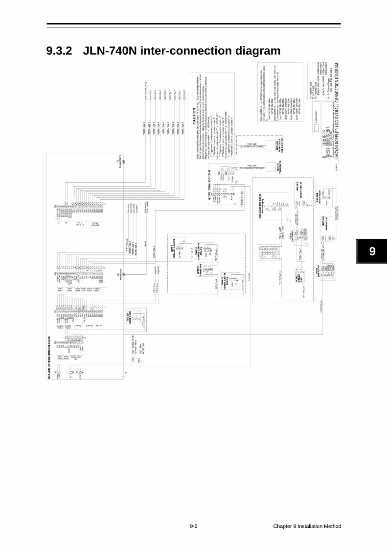
9-5 Chapter 9 Installation Method
9
9.3.2 JLN-740N inter-connection diagram
*1)T
TYCS
LA-1
*1)T
TYCS
LA-1
*1)T
TYCS
LA-1
IEC6
1162
-1
IEC6
1162
-1
IEC6
1162
-1
NQA-
7040
DIS
TRIB
UTIO
N PR
OCES
SOR
JLN-
740N
DOP
PLER
LOG
OVER
ALL
CONN
ECTI
ON D
IAGR
AM
IEC6
1162
-1*1
)TTY
CSLA
-1
J10
Disp
lay(O
NLY)
J11
Maint
enan
ce
J7Ba
ttery
24
V+ - J1
AC IN
L N FG
Ship’
s Bac
kup D
C24V
For P
ower
Alar
m*1
)D1
Ship’
s Main
A
C100
,230V
1 2 3 4 5 6 7 8 9 10 11 12 13 14TB1
DimmerSerial
DimmerAnalog
MID(Main Display)
RX-A
RX-B
TX-A
TX-B
RX+
RX-
DC26
V OU
TGN
DRX
-ARX
-BTX
-ATX
-BON
/OFF
+ON
/OFF
-
1 2 3 4 5 6 7 8 9 10 11 12 13 14 15 16 17 18 19 20 21 22 23 24TB2
Analo
g OU
T+An
alog
OUT-
EL O
UTEL
OUT
Analo
g OU
T+An
alog
OUT-
EL O
UTEL
OUT
DC26
V OU
TGN
DRX
-ARX
-BTX
-ATX
-BDC
26V
OUT
GND
RX-A
RX-B
TX-A
TX-B
TX1+
TX1-
TX2+
TX2-
Remote 1Analog
Display 1
1 1 2 2
DATA EL
1 L
NWW
-24
REMO
TE D
ISPL
AYAN
ALOG
*4)T
TYCS
LA-4
NCM-
329
DIMM
ER U
NIT
1 1 2 2
1 1 2 2
*4)T
TYCS
LA-4
NWW
-7DI
STAN
CE C
OUNT
ER
DIST
ANCE
1 2 3 4
+
*1)T
TYCS
LA-1
NWZ-
4640
MAIN
DIS
PLAY
DC12
/24V
DA
TAco
nnec
tor
SENS
OR/
DATA
2co
nnec
tor
WHI
TEB
GREE
N BR
OWN
RED
*2)
Powe
r cab
le
CFQ
-576
6A (J
RC 2m
)3 71 2 5 64
IEC6
1162
-1*1
)TTY
CSLA
-1
IEC6
1162
-1*1
)TTY
CSLA
-1
IEC6
1162
-1*1
)TTY
CSLA
-1
IEC6
1162
-1*1
)TTY
CSLA
-1
*1)T
TYCS
LA-4
*1)T
TYCS
LA-4
*1)T
TYCS
LA-4
*1)T
TYCS
LA-1
*1)T
TYCS
LA-4
Powe
r Alar
mSy
stem
Alarm
Spee
d Al
armSe
rial A
larm
*1)L
ANBr
idge
Inter
face
(Sen
sor L
AN S
W)
NCM-
227
DIMM
ER U
NIT
+1 2 3 4
1+
1-
3+
3-
1+
1- 3+
3-
*1)T
TYCS
LA-1
GPS
in (D
ATE,
UTC
)
1 2 3 4 5 6 7 8 9 10 11 12 13 14 15 16 17 18 19 20 21 22 23 24TB4
IEC61162-1TX No.2
TX-A
(SAT
LOG)
TX-B
(SAT
LOG)
RX1-
A(RO
T)RX
1-B(
ROT)
RX2-
A(GP
S)RX
2-B(
GPS)
RX3-
A(Sp
are)
RX3-
B(Sp
are)
TX1-
ATX
1-B
TX2-
ATX
2-B
TX3-
ATX
3-B
TX4-
ATX
4-B
TX5-
ATX
5-B
TX6-
ATX
6-B
TX7-
ATX
7-B
TX8-
ATX
8-B
IEC61162-1TX No.1 RXTX
1 2 3 4 5 6 7 8 9 10 11 12 13 14 15 16 17 18 19 20 21 22 23 24TB3
ALM-
NCAL
M-CO
MBZ
IN+
BZ IN
-AL
M-NC
ALM-
COM
BZ O
UT-C
OMBZ
OUT
-NO
BZ IN
+BZ
IN-
ALM-
NCAL
M-CO
MRX
-ARX
-BTX
-ATX
-B TX+
TX-
RX-A
RX-B
TX-A
TX-B
PWR_
EN+
PWR_
EN-
Power Alarm
SystemAlarm
SpeedAlarm
SerialAlarm
SignalProcessor
DistanceCounter
AnalogDisplay 2 Remote 2 Log Pulse
1+
1-
2+
2-
1+
1- 2+
2-
NWW
-25
REMO
TE D
ISPL
AYAN
ALOG 1 1 2 2
DATA EL
1 L
*1)T
TYCS
LA-4
Log P
ulse1
*1)T
TYCS
LA-1
Log P
ulse2
*1
)TTY
CSLA
-1
*2)C
FS-6
680A
(App
rox.
1.2m
)
1 2 3 4 5 6 7 8 + S -
RED
ORG
YEL
GRN
BLU
PUR
GRY
WHT PN
K
SHIE
LD1-3+ 3- 2+ 2- 1+
NKF-
547
TRAN
SDUC
ER
NJC-
70S
SIG
NAL
PRO
CESS
OR
J202 1 2 3 4
TD_F
ORE
TD_A
FT
1 21:T
herm
o+ J103
2:The
rmo-
1 2 3 4 L N FG1 2
AC IN
J2
J2
AC O
UTL N FG
J4J203
UP LI
NK A
UP LI
NK B
DOW
N LIN
K A
DOW
N LIN
K B
*1) D
1 or D
2
EN+
EN-
NWZ-
4610
REMO
TE D
ISPL
AY
DC12
/24V
DA
TAco
nnec
tor
SENS
OR/
DATA
2co
nnec
tor
PURP
LE
RED
3 71 2 5 64
NCM-
227
DIMM
ER
UNIT
1 2 3 4
4 5*5
)TTY
CSLA
-1
1+
1- 2+
2-*5
)TTY
CSLA
-4
2+
2-
2+
2-
1+
1-
2+
2-
3-
3+ 1+
1-
2+
2-
12
4+
4-
84+
4-
YELL
OW
ORAN
GE
NWZ-
650S
DR N
WZ-
840S
DRRe
mot
e Disp
layP1
1 1 2+
P12
RED
BLK
1 2 3 4 5 6 7 8
ORG
YEL
GRN
BLU
Tx+
Tx-
GND
Rx+
Rx-
NO C NC
+ -
1+
1-
2+
2-
1+
1-
3+
3-
2+
2-
3+
3-
2+
2-
3+
3-
1-
1+
*1)
CQD-
10JU
NCTI
ON B
OX
CQD-
10JU
NCTI
ON B
OX
BLK
With
fuse
NKF-
531E
TRAN
SDUC
ER(G
ate V
alve T
ype)
is op
tiona
l item
*2)Transducer Cable Dia 13.2(JRC 40m)
*1):
Ship
yard
Sup
ply*2
): JR
C Su
pply
*3):
Ship
yard
Sup
ply
If S
hip’
s Main
230
VAC,
D1(
Max 5
00m
)
D
2(Ma
x 500
m)
If Ship
’s M
ain 1
00VA
C, D
1(Ma
x 320
m)
D2(
Max 5
00m
)*4
), *5
): S
hipya
rd S
upply
T
otal 1
00m
of the
two
cable
s
Whe
n re
trofit
from
JLN
- 205
Mk I
I, whe
n usin
g exis
ting c
able
TTYC
SLA
- 4 fo
r com
mun
icatio
n and
using
the r
emain
ing 1
pair a
s AC 1
pair
230V
AC M
ax 2
80m
10
0VAC
Max
160
mW
hen
retro
fit fro
m JL
N - 5
50, w
hen u
sing e
xistin
g cab
le TT
YCSL
A -
7 for
comm
unica
tion a
nd us
ing th
e rem
aining
4 p
airs a
s AC
1pa
ir 23
0VAC
Max
280
m
100V
AC M
ax 1
60m
2pa
irs 23
0VAC
Max
500m
10
0VAC
Max
320
m 3
pairs
230V
AC M
ax 5
00m
10
0VAC
Max
480
m 4
pairs
230V
AC M
ax 5
00m
10
0VAC
Max
500
m
D1: 0
.6/1
kV D
PYC-
1.5
D2: 0
.6/1
kV D
PYC-
2.5
TTYC
SLA-
1:15
0/25
0 V
TTYC
SLA-
1TT
YCSL
A-4
:150/
250
V TT
YCSL
A-4
LAN
:CAT
-5 L
AN C
able
*Wate
rproo
f Eth
ernet
Cab
le(Sh
ield T
wist-
Pair
cable
with
wate
rpro
of)
*1)C
OPPE
R PL
ATE
*1)
シールド
2019
0819
CGC-
300B
Exte
rnal
Buzz
er
Buzz
er1 2 3 4
+
CAUT
ION
Whe
n co
nnec
ting
the T
rans
duce
r Cab
le to
the S
ignal
Proc
esso
r (NJ
C-70
S), if
the w
iring i
s diffe
rent
from
the fig
ure, t
he sh
ip sp
eed w
ill no
t be d
isplay
ed co
rrectl
y. Al
so, I
f a tr
ansm
ission
volta
ge is
appli
ed
to the
ther
misto
r due
to in
corre
ct wi
ring,
the
therm
istor
burns
out a
nd ca
nnot
be re
paire
d.Pl
ease
insta
ll whil
e che
cking
the c
onne
ction
diag
ram
and
the eq
uipme
nt to
the fo
llowi
ng st
atem
ent.
>>Co
nnec
t the c
able
marke
d "2"
to J2
02 (T
herm
o)
"+" C
oppe
r wire
: Con
nect
to co
nnec
tor nu
mber
"1"
"-"
Shie
ld wi
re: C
onne
ct to
conn
ector
numb
er "2
">>
Conn
ect th
e ca
ble m
arke
d with
"3" t
o J10
3 (T
D_AF
T)
"+" C
oppe
r wire
: Con
nect
to co
nnec
tor nu
mber
"1"
"-"
Shie
ld wi
re: C
onne
ct to
conn
ector
numb
er "2
">>
Conn
ect th
e ca
ble m
arke
d with
"1" t
o J10
3 (T
D_FO
RE)
"+
" Cop
per w
ire: C
onne
ct to
conn
ector
numb
er "4
"
"-" S
hield
wire
: Con
nect
to co
nnec
tor nu
mber
"3"
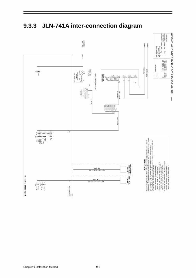
Chapter 9 Installation Method 9-6
9.3.3 JLN-741A inter-connection diagram
NJC-
70S
SIGN
AL P
ROCE
SSOR
JLN-
741A
DOP
PLER
LOG
OVER
ALL C
ONNE
CTIO
N DI
AGRA
M
Ship’
s Main
10
0,23
0VAC
*1)T
TYCS
LA-4
2+
*2)Transducer Cable Dia 13.2(JRC 30m)
NKF-
547
TRAN
SDUC
ER
J202 1 2 3 4
TD_F
ORE
TD_A
FT
1 21:T
herm
o+
J103
2:The
rmo-
1 2 3 4
L N FG
1 2
AC IN
J2
J4J203
UP LI
NK A
UP LI
NK B
DOW
N LIN
K A
DOW
N LIN
K B
*3)D
1 or D
2
EN+
EN-
1 2 3 4 5 6 7 8 + S - 12
RED
ORG
YEW
GRN
BLU
PUR
GRY
WHT PN
K
SHIE
LD
2+ 2- 3+ 3- 1+
+ -
2- 3-3+ 1+1-
1+ 1-2+ 2- 3+ 3-
NWZ-
510S
DWMa
in D
isplay
P11 1 2
+
P12
+RED
-BLK
1 2 3 4 5 6 7 8
1ORG
2YEW
3GRN
4BLU
Tx+
Tx-
GND
Rx+
Rx-
NO C NC
6GRY
7WHT
*1)C
OPPE
R PL
ATE
*1)D
1 or
D2
D1: 0
.6/1
kV D
PYC-
1.5
D2: 0
.6/1
kV D
PYC-
2.5
TTYC
SLA-
1:15
0/25
0 V
TTYC
SLA-
1TT
YCSL
A-4
:150/
250
V TT
YCSL
A-4
is op
tiona
l item
P19 1 2 3 4 5 6 7 8 9 10 11 12
Tx+
Tx-
Rx+
Rx-
Tx+
Tx-
Rx+
Rx-
Tx+
Tx-
Rx+
Rx-
*1)T
TYCS
LA-1
NMEA
1
*1)T
TYCS
LA-1
NMEA
2
NKF-
531E
TRAN
SDUC
ER(G
ate V
alve T
ype)
*2)Transducer Cable Dia 13.2(JRC 40m)
BLK
*1):
Ship
yard
Sup
ply*2
): JR
C Su
pply
*3):
Ship
yard
Sup
ply
If S
hip’
s Main
230
VAC,
D1(
Max 5
00m
)
D
2(Ma
x 500
m)
If Ship
’s M
ain 1
00VA
C, D
1(Ma
x 320
m)
D2(
Max 5
00m
)
Ship’
s Main
10
0,23
0VAC
*1)D
1
NBA-
5143
POW
ER S
UPPL
Y UN
IT
COM
100V
220V
FG-
+AC
INDC
24V
OUT
If Ship
’s M
ain A
C100
V
NBA-
5143
POW
ER S
UPPL
Y UN
IT
COM
100V
220V
FG-
+AC
INDC
24V
OUT
1-
5 6 7 8
UP LI
NK (S
P) A
UP LI
NK (S
P) B
Tx Tr
ig A
Tx Tr
ig B
9BLK
2019
0819
*Use
isola
ted po
wer s
upply
CAUT
ION
Whe
n co
nnec
ting
the T
rans
duce
r Cab
le to
the S
ignal
Proc
esso
r (NJ
C-70
S), if
the w
iring i
s diffe
rent
from
the fig
ure, t
he sh
ip sp
eed w
ill no
t be d
isplay
ed co
rrectl
y. Al
so, I
f a tr
ansm
ission
volta
ge is
appli
ed
to the
ther
misto
r due
to in
corre
ct wi
ring,
the
therm
istor
burns
out a
nd ca
nnot
be re
paire
d.Pl
ease
insta
ll whil
e che
cking
the c
onne
ction
diag
ram
and
the eq
uipme
nt to
the fo
llowi
ng st
atem
ent.
>>Co
nnec
t the c
able
marke
d "2"
to J2
02 (T
herm
o)
"+" C
oppe
r wire
: Con
nect
to co
nnec
tor nu
mber
"1"
"-"
Shie
ld wi
re: C
onne
ct to
conn
ector
numb
er "2
">>
Conn
ect th
e ca
ble m
arke
d with
"3" t
o J10
3 (T
D_AF
T)
"+" C
oppe
r wire
: Con
nect
to co
nnec
tor nu
mber
"1"
"-"
Shie
ld wi
re: C
onne
ct to
conn
ector
numb
er "2
">>
Conn
ect th
e ca
ble m
arke
d with
"1" t
o J10
3 (T
D_FO
RE)
"+
" Cop
per w
ire: C
onne
ct to
conn
ector
numb
er "4
"
"-" S
hield
wire
: Con
nect
to co
nnec
tor nu
mber
"3"
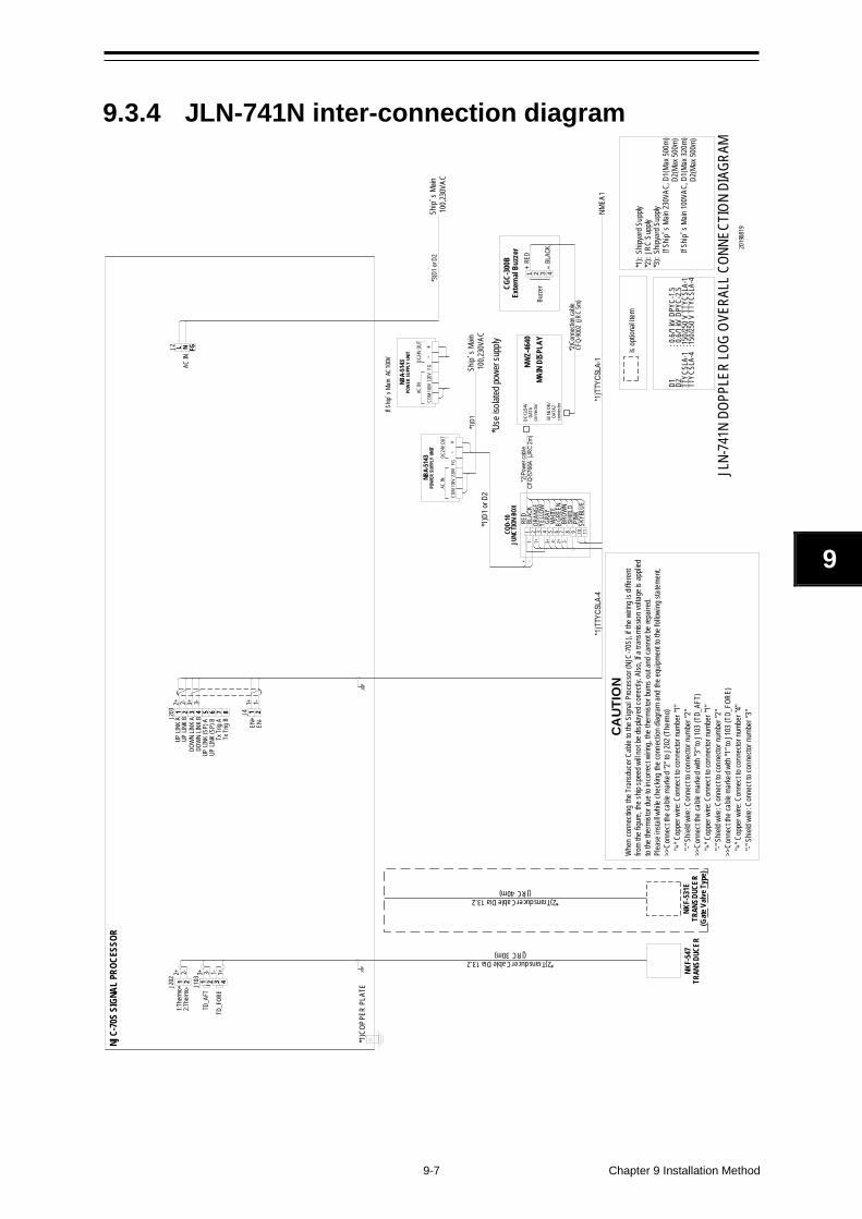
9-7 Chapter 9 Installation Method
9
9.3.4 JLN-741N inter-connection diagram
NJC-
70S
SIGN
AL P
ROCE
SSOR
JLN-
741N
DOP
PLER
LOG
OVER
ALL
CONN
ECTI
ON D
IAGR
AM
Ship’
s Main
10
0,23
0VAC
*2)Transducer Cable Dia 13.2(JRC 30m)
NKF-
547
TRAN
SDUC
ER
J202 1 2 3 4
TD_F
ORE
TD_A
FT
1 21:T
herm
o+ J103
2:The
rmo-
1 2 3 4
L N FG
1 2
AC IN
J2
J4J203
UP LI
NK A
UP LI
NK B
DOW
N LIN
K A
DOW
N LIN
K B
*3)D
1 or D
2
EN+
EN-
+ -DC
12/2
4V
DATA
conn
ecto
r
GRAY
WHI
TEB
GREE
N BR
OWN
RED
3 71 2 5 641+1- 3+ 3- 2+ 2-
1+ 1-2+ 2- 3+ 3-
8
YELL
OWOR
ANGE
2+ 2- 3-3+ 1+1-
is op
tiona
l item
D1: 0
.6/1
kV D
PYC-
1.5
D2: 0
.6/1
kV D
PYC-
2.5
TTYC
SLA-
1:15
0/25
0 V
TTYC
SLA-
1TT
YCSL
A-4
:150/
250
V TT
YCSL
A-4
NKF-
531E
TRAN
SDUC
ER(G
ate V
alve T
ype)
*2)Transducer Cable Dia 13.2(JRC 40m)
CQD-
10JU
NCTI
ON B
OX
9PI
NK10 11
SKYB
LUE
NMEA
1
*1):
Ship
yard
Sup
ply*2
): JR
C Su
pply
*3):
Ship
yard
Sup
ply
If S
hip’
s Main
230
VAC,
D1(
Max 5
00m
)
D
2(Ma
x 500
m)
If Ship
’s M
ain 1
00VA
C, D
1(Ma
x 320
m)
D2(
Max 5
00m
)
*1)C
OPPE
R PL
ATE
*1)D
1 or
D2
Ship’
s Main
10
0,23
0VAC
*1)D
1
NBA-
5143
POW
ER S
UPPL
Y UN
IT
COM
100V
220V
FG-
+AC
INDC
24V
OUT
If Ship
’s M
ain A
C100
V
NBA-
5143
POW
ER S
UPPL
Y UN
IT
COM
100V
220V
FG-
+AC
INDC
24V
OUT
5 6 7 8
UP LI
NK (S
P) A
UP LI
NK (S
P) B
Tx Tr
ig A
Tx Tr
ig B
2019
0819
*Use
isola
ted po
wer s
upply
NWZ-
4640
MAIN
DIS
PLAY
SENS
OR/
DATA
2co
nnec
tor
*2)
Conn
ectio
n ca
ble
CFQ
-900
2 (JR
C 5m
)
CGC-
300B
Exte
rnal
Buzz
er
Buzz
er1 2 3 4
+ RE
D
CAUT
ION
Whe
n co
nnec
ting
the T
rans
duce
r Cab
le to
the S
ignal
Proc
esso
r (NJ
C-70
S), if
the w
iring i
s diffe
rent
from
the fig
ure, t
he sh
ip sp
eed w
ill no
t be d
isplay
ed co
rrectl
y. Al
so, I
f a tr
ansm
ission
volta
ge is
appli
ed
to the
ther
misto
r due
to in
corre
ct wi
ring,
the
therm
istor
burns
out a
nd ca
nnot
be re
paire
d.Pl
ease
insta
ll whil
e che
cking
the c
onne
ction
diag
ram
and
the eq
uipme
nt to
the fo
llowi
ng st
atem
ent.
>>Co
nnec
t the c
able
marke
d "2"
to J2
02 (T
herm
o)
"+" C
oppe
r wire
: Con
nect
to co
nnec
tor nu
mber
"1"
"-"
Shie
ld wi
re: C
onne
ct to
conn
ector
numb
er "2
">>
Conn
ect th
e ca
ble m
arke
d with
"3" t
o J10
3 (T
D_AF
T)
"+" C
oppe
r wire
: Con
nect
to co
nnec
tor nu
mber
"1"
"-"
Shie
ld wi
re: C
onne
ct to
conn
ector
numb
er "2
">>
Conn
ect th
e ca
ble m
arke
d with
"1" t
o J10
3 (T
D_FO
RE)
"+
" Cop
per w
ire: C
onne
ct to
conn
ector
numb
er "4
"
"-" S
hield
wire
: Con
nect
to co
nnec
tor nu
mber
"3"

Chapter 9 Installation Method 9-8
(This page intentionally left blank)
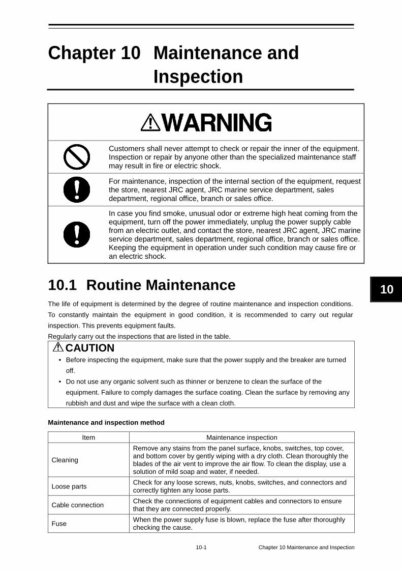
10-1 Chapter 10 Maintenance and Inspection
10
Chapter 10 Maintenance and Inspection
Customers shall never attempt to check or repair the inner of the equipment. Inspection or repair by anyone other than the specialized maintenance staff may result in fire or electric shock.
For maintenance, inspection of the internal section of the equipment, request the store, nearest JRC agent, JRC marine service department, sales department, regional office, branch or sales office.
In case you find smoke, unusual odor or extreme high heat coming from the equipment, turn off the power immediately, unplug the power supply cable from an electric outlet, and contact the store, nearest JRC agent, JRC marine service department, sales department, regional office, branch or sales office. Keeping the equipment in operation under such condition may cause fire or an electric shock.
10.1 Routine Maintenance The life of equipment is determined by the degree of routine maintenance and inspection conditions. To constantly maintain the equipment in good condition, it is recommended to carry out regular inspection. This prevents equipment faults. Regularly carry out the inspections that are listed in the table.
CAUTION • Before inspecting the equipment, make sure that the power supply and the breaker are turned
off. • Do not use any organic solvent such as thinner or benzene to clean the surface of the
equipment. Failure to comply damages the surface coating. Clean the surface by removing any rubbish and dust and wipe the surface with a clean cloth.
Maintenance and inspection method
Item Maintenance inspection
Cleaning
Remove any stains from the panel surface, knobs, switches, top cover, and bottom cover by gently wiping with a dry cloth. Clean thoroughly the blades of the air vent to improve the air flow. To clean the display, use a solution of mild soap and water, if needed.
Loose parts Check for any loose screws, nuts, knobs, switches, and connectors and correctly tighten any loose parts.
Cable connection Check the connections of equipment cables and connectors to ensure that they are connected properly.
Fuse When the power supply fuse is blown, replace the fuse after thoroughly checking the cause.
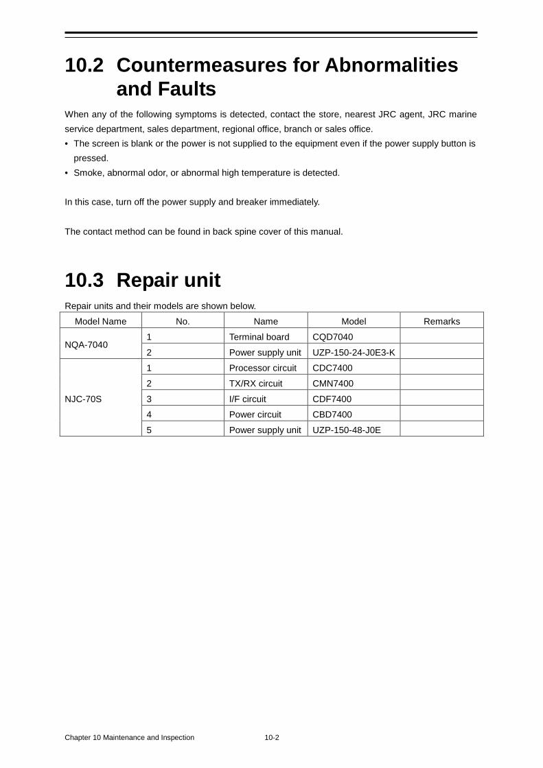
Chapter 10 Maintenance and Inspection 10-2
10.2 Countermeasures for Abnormalities and Faults
When any of the following symptoms is detected, contact the store, nearest JRC agent, JRC marine service department, sales department, regional office, branch or sales office. • The screen is blank or the power is not supplied to the equipment even if the power supply button is
pressed. • Smoke, abnormal odor, or abnormal high temperature is detected. In this case, turn off the power supply and breaker immediately. The contact method can be found in back spine cover of this manual.
10.3 Repair unit Repair units and their models are shown below.
Model Name No. Name Model Remarks
NQA-7040 1 Terminal board CQD7040
2 Power supply unit UZP-150-24-J0E3-K
NJC-70S
1 Processor circuit CDC7400
2 TX/RX circuit CMN7400
3 I/F circuit CDF7400 4 Power circuit CBD7400
5 Power supply unit UZP-150-48-J0E
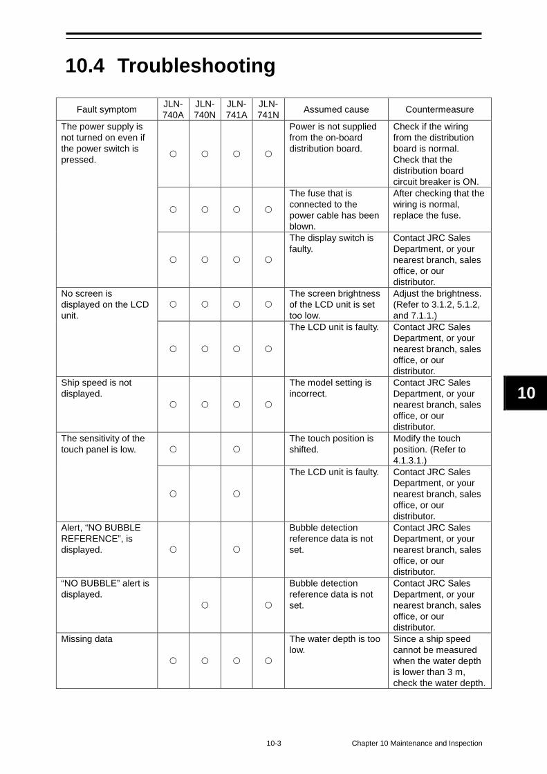
10-3 Chapter 10 Maintenance and Inspection
10
10.4 Troubleshooting
Fault symptom JLN- 740A
JLN- 740N
JLN- 741A
JLN- 741N Assumed cause Countermeasure
The power supply is not turned on even if the power switch is pressed.
Power is not supplied from the on-board distribution board.
Check if the wiring from the distribution board is normal. Check that the distribution board circuit breaker is ON.
The fuse that is connected to the power cable has been blown.
After checking that the wiring is normal, replace the fuse.
The display switch is faulty.
Contact JRC Sales Department, or your nearest branch, sales office, or our distributor.
No screen is displayed on the LCD unit.
The screen brightness of the LCD unit is set too low.
Adjust the brightness. (Refer to 3.1.2, 5.1.2, and 7.1.1.)
The LCD unit is faulty. Contact JRC Sales Department, or your nearest branch, sales office, or our distributor.
Ship speed is not displayed.
The model setting is incorrect.
Contact JRC Sales Department, or your nearest branch, sales office, or our distributor.
The sensitivity of the touch panel is low.
The touch position is shifted.
Modify the touch position. (Refer to 4.1.3.1.)
The LCD unit is faulty. Contact JRC Sales Department, or your nearest branch, sales office, or our distributor.
Alert, “NO BUBBLE REFERENCE”, is displayed.
Bubble detection reference data is not set.
Contact JRC Sales Department, or your nearest branch, sales office, or our distributor.
“NO BUBBLE” alert is displayed.
Bubble detection reference data is not set.
Contact JRC Sales Department, or your nearest branch, sales office, or our distributor.
Missing data
The water depth is too low.
Since a ship speed cannot be measured when the water depth is lower than 3 m, check the water depth.
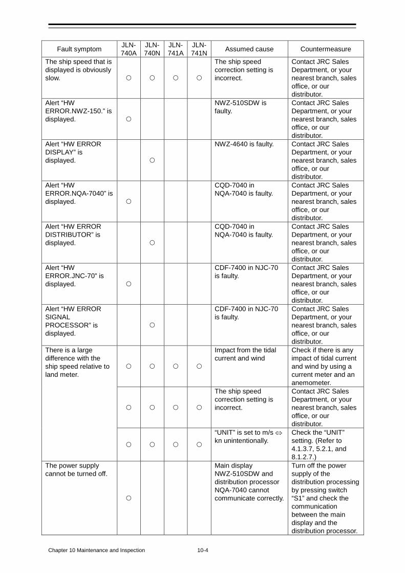
Chapter 10 Maintenance and Inspection 10-4
Fault symptom JLN- 740A
JLN- 740N
JLN- 741A
JLN- 741N Assumed cause Countermeasure
The ship speed that is displayed is obviously slow.
The ship speed correction setting is incorrect.
Contact JRC Sales Department, or your nearest branch, sales office, or our distributor.
Alert “HW ERROR.NWZ-150.” is displayed.
NWZ-510SDW is faulty.
Contact JRC Sales Department, or your nearest branch, sales office, or our distributor.
Alert “HW ERROR DISPLAY” is displayed.
NWZ-4640 is faulty. Contact JRC Sales Department, or your nearest branch, sales office, or our distributor.
Alert “HW ERROR.NQA-7040” is displayed.
CQD-7040 in NQA-7040 is faulty.
Contact JRC Sales Department, or your nearest branch, sales office, or our distributor.
Alert “HW ERROR DISTRIBUTOR” is displayed.
CQD-7040 in NQA-7040 is faulty.
Contact JRC Sales Department, or your nearest branch, sales office, or our distributor.
Alert “HW ERROR.JNC-70” is displayed.
CDF-7400 in NJC-70 is faulty.
Contact JRC Sales Department, or your nearest branch, sales office, or our distributor.
Alert “HW ERROR SIGNAL PROCESSOR” is displayed.
CDF-7400 in NJC-70 is faulty.
Contact JRC Sales Department, or your nearest branch, sales office, or our distributor.
There is a large difference with the ship speed relative to land meter.
Impact from the tidal current and wind
Check if there is any impact of tidal current and wind by using a current meter and an anemometer.
The ship speed correction setting is incorrect.
Contact JRC Sales Department, or your nearest branch, sales office, or our distributor.
“UNIT” is set to m/s ⇔ kn unintentionally.
Check the “UNIT” setting. (Refer to 4.1.3.7, 5.2.1, and 8.1.2.7.)
The power supply cannot be turned off.
Main display NWZ-510SDW and distribution processor NQA-7040 cannot communicate correctly.
Turn off the power supply of the distribution processing by pressing switch “S1” and check the communication between the main display and the distribution processor.
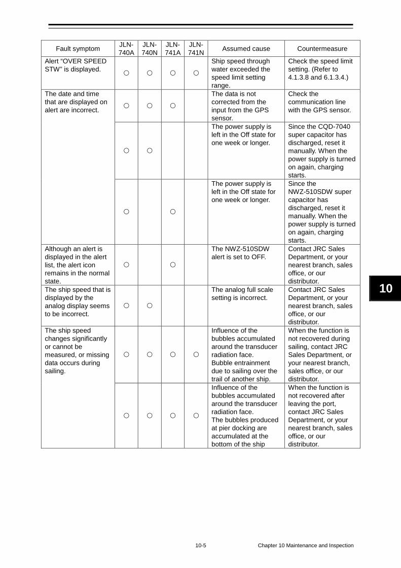
10-5 Chapter 10 Maintenance and Inspection
10
Fault symptom JLN- 740A
JLN- 740N
JLN- 741A
JLN- 741N Assumed cause Countermeasure
Alert “OVER SPEED STW” is displayed.
Ship speed through water exceeded the speed limit setting range.
Check the speed limit setting. (Refer to 4.1.3.8 and 6.1.3.4.)
The date and time that are displayed on alert are incorrect.
The data is not corrected from the input from the GPS sensor.
Check the communication line with the GPS sensor.
The power supply is left in the Off state for one week or longer.
Since the CQD-7040 super capacitor has discharged, reset it manually. When the power supply is turned on again, charging starts.
The power supply is left in the Off state for one week or longer.
Since the NWZ-510SDW super capacitor has discharged, reset it manually. When the power supply is turned on again, charging starts.
Although an alert is displayed in the alert list, the alert icon remains in the normal state.
The NWZ-510SDW alert is set to OFF.
Contact JRC Sales Department, or your nearest branch, sales office, or our distributor.
The ship speed that is displayed by the analog display seems to be incorrect.
The analog full scale setting is incorrect.
Contact JRC Sales Department, or your nearest branch, sales office, or our distributor.
The ship speed changes significantly or cannot be measured, or missing data occurs during sailing.
Influence of the bubbles accumulated around the transducer radiation face. Bubble entrainment due to sailing over the trail of another ship.
When the function is not recovered during sailing, contact JRC Sales Department, or your nearest branch, sales office, or our distributor.
Influence of the bubbles accumulated around the transducer radiation face. The bubbles produced at pier docking are accumulated at the bottom of the ship
When the function is not recovered after leaving the port, contact JRC Sales Department, or your nearest branch, sales office, or our distributor.

Chapter 10 Maintenance and Inspection 10-6
(This page intentionally left blank)
11-1 Chapter 11 After-Sales Service
11
Chapter 11 After-Sales Service 11.1 Requesting Repair When suspecting “fault”, stop using the equipment and contact the store, nearest JRC agent, JRC marine service department, sales department, regional office, branch or sales office. Repair under the warranty period When the equipment becomes faulty while it is used in the normal utilization condition according to the description/instruction in the instruction manual, the distributor or JRC will repair the equipment without charge. If the equipment becomes faulty due to mishandling, negligence, or for a reason beyond control such as natural disaster or fire, repair is charged. Repair beyond the warranty period When the functions can be recovered by repair, JRC will repair the equipment with charge according to the customer’s request. Necessary information • Product name, model name, manufacturing date, and manufacturing number • Condition of abnormality (as detailed as possible) • Office name or organization name, address, telephone number and FAX number
Chapter 11 After-Sales Service 11-2
11.2 Recommendation of Inspection and Maintenance
The performance may deteriorate due to the aging of parts although the degree varies depending on the utilization condition. For the inspection and maintenance separate from the normal maintenance, contact the store, nearest JRC agent, JRC marine service department, sales department, regional office, branch or sales office. This service is charged. For any questions regarding the after-sales service, please contact your distributor/agent, JRC branch, sales office, or liaison office. The contact method can be found in back spine cover of this manual.
12-1 Chapter 12 Disposal
12
Chapter 12 Disposal
Disposal treatment of this equipment must comply with the rules and regulations of the Government or the local government.
Disposal of this equipment Disposal treatment of this equipment must comply with the regulations or rules of the Government or the local government that controls the location of the disposal.

Chapter 12 Disposal 12-2
(This page intentionally left blank)
13-1 Chapter 13 Specification
1
13
1
Chapter 13 Specification 13.1. General Specification 13.1.1. JLN-740A Water speed measuring system Dual – beam pulse Doppler system Operation frequency 2 MHz Fore/after speed measurement scale -10.00 to +40.00 kn No. of digits displayed Fixed 4 or 3 digits selectable Minimum digital display unit 0.01 kn or 0.1 kn selectable Sailing display range 0 to 999999.99NM
(0 to 9999.99NM for optional NWW-7 0 to 99999.99NM for optional NWZ-4610)
Water speed measurable depth 3.0 m deeper than the transducer surface Ship speed accuracy 1% of the speed of the ship, or 0.1 kn whichever is
greater Total distance accuracy 1% of the distance run by the ship in 1h or 0.1
nautical miles in each hour whichever is greater Power consumption 50 W 60VA (for 100VAC)
50 W 150VA (for 230VAC) Power consumption of resource alert circuit 0.25 W (normal condition)
0.5 W (when power fail alert happening)
13.1.2. JLN-740N Water speed measuring system Dual – beam pulse Doppler system Operation frequency 2 MHz Fore/after speed measurement scale -10.00 to +40.00 kn No. of digits displayed Fixed 4 or 3 digits selectable Minimum digital display unit 0.01 kn or 0.1 kn selectable Minimum analog display unit Scale: 0.5 kn units
Value: 5.0 kn units Sailing display range 0 to 99999.99NM
(0 to 9999.99NM for optional NWW-7 0 to 99999.99NM for optional NWZ-4610)
Water speed measurable depth 3.0 m deeper than the transducer surface Ship speed accuracy 1% of the speed of the ship, or 0.1 kn whichever is
greater Total distance accuracy 1% of the distance run by the ship in 1h or 0.1
nautical miles in each hour whichever is greater Power consumption 40 W 55VA (for 100VAC) 45 W 145VA (for 230VAC) Power consumption of resource alert circuit 0.25 W (normal condition)
0.5 W (when power fail alert happening)
Chapter 13 Specification 13-2
13.1.3. JLN-741A Water speed measuring system Dual – beam pulse Doppler system Operation frequency 2 MHz Fore/after speed measurement scale -10.00 to +40.00 kn No. of digits displayed Fixed 4 or 3 digits selectable Minimum digital display unit 0.01 kn or 0.1 kn selectable Sailing display range 0 to 999999.99NM Water speed measurable depth 3.0 m deeper than the transducer surface Ship speed accuracy 1 % of the speed of the ship, or 0.1 kn whichever is
greater Total distance accuracy 1% of the distance run by the ship in 1h or 0.1
nautical miles in each hour whichever is greater Power consumption 20 W 30VA (for 100VAC)
20 W 75VA (for 230VAC)
13.1.4. JLN-741N Water speed measuring system Dual – beam pulse Doppler system Operation frequency 2 MHz Fore/after speed measurement scale -10.00 to +40.00 kn No. of digits displayed Fixed 4 or 3 digits selectable Minimum digital display unit 0.01 kn or 0.1 kn selectable Minimum analog display unit Scale: 0.5 kn units
Value: 5.0 kn units Sailing display range 0 to 99999.99NM Water speed measurable depth 3.0 m deeper than the transducer surface Ship speed accuracy 1 % of the speed of the ship, or 0.1 kn whichever is
greater Total distance accuracy 1% of the distance run by the ship in 1h or 0.1
nautical miles in each hour whichever is greater Power consumption 20 W 25VA (for 100VAC)
20 W 75VA (for 230VAC)

13-3 Chapter 13 Specification
1
13
1
13.2. JLN-740A/741A Main Display NWZ-510SDW CAUTION JLN-741A/741N does not use NWZ-510SDW
13.2.1. Display Unit Display unit 5-inch color LCD, 480(H) × 800(V) pixels (WVGA) Pixel pitch 0.135 mm Operation buttons Touch panel and power supply button Backlight (LED) LCD and power supply button Maximum luminance 300 cd/m2 or more (when maximum luminance is set) Viewing distance 1 m Minimum character visually distance 30 cm Fore/after speed visually distance 4.6 m Dimmer function adjustments Selection from daytime(DAY), intermediate(DUSK),
nighttime(NIGHT) and 17-level
13.2.2. Electrical Specifications Power supply voltage 24VDC (18V to 34V) Power consumption About 8 W
13.2.3. Environmental Requirements Operating temperature range -15°C to +55°C (IEC 60945 ed.4 Protected equipment) Storage temperature range -20°C to +70°C Protection level Equivalent to IP22 (front at installation of flush-mount) Vibration Complies with IEC 60945 ed.4 EMC Complies with IEC 60945 ed.4 Compass safety distance 0.1 m (STD), 0.1 m (STEER)
13.2.4. Mechanical Specifications External size 96 mm (width) × 180 mm (height) × 80 mm (depth), protrusions
excluded Mass 1.2 kg Color Munsell N2.5 Mounting Desktop or flush-mount
Chapter 13 Specification 13-4
13.2.5. External Interface [JLN-741A configuration] IEC 61162-1 Output: 2ch
13-5 Chapter 13 Specification
1
13
1
13.3. JLN-740N/741N Main Display NWZ-4640 CAUTION JLN-741A/741N does not use NWZ-4640
13.3.1. Display Unit Display unit 4.5 inch monochrome LCD 128 × 64 dots Pixel pitch 0.74 mm Backlight White LED or orange LED (selectable) Dimmer Levels 4 levels (Bright, Medium, Dark, OFF) Dimmer control Key or external dimmer unit Contrast 13 levels Key 12 keys Operation buttons Viewing distance 1 m Fore/after speed visual distance 8.0 m
13.3.2. Electrical Specifications Power supply voltage 12/24VDC (10.8V to 31.2V) Power consumption Less than 2.5 W Memory backup Flash memory
13.3.3. Environmental Requirements Operating temperature range -15°C to +55°C (IEC 60945 ed.4 Protected equipment) Storage temperature range -20°C to +70°C Protection level Equivalent to IP55 Vibration Complies with IEC 60945 ed.4 EMC Complies with IEC 60945 ed.4 Compass safety distance 1.00 m (STD), 0.5 m (STEER)
13.3.4. Mechanical Specifications External size 142(W) × 142(H) × 92(D) mm (without Base unit) 175(W) × 162(H) × 92(D) mm (Include Base unit) Mass 0.8 kg Body Color Munsell N2.5 Installation Desktop or flush-mount
13.3.5. External interface [JLN-741N configuration] IEC 61162-1 Output: 1ch
Chapter 13 Specification 13-6
13.4. Distribution Processor NQA-7040 CAUTION JLN-741A/741N does not use NQA-7040
13.4.1. Electrical Specifications Power supply voltage 100/230VAC (90V to 253V) Power consumption Maximum 30 W (include sensor and displays power)
13.4.2. Environmental Requirements Operating temperature range -15°C to +55°C (IEC 60945 ed.4 Protected equipment) Storage temperature range -20°C to +70°C Protection level IP22 Vibration Complies with IEC 60945 ed.4 EMC Complies with IEC 60945 ed.4 Compass safety distance 0.8 m (STD), 0.4 m (STEER)
13.4.3. Mechanical Specifications External size 300 mm (width) × 490 mm (height) × 130 mm (depth), protrusions
excluded Mass About 6 kg Color Munsell N2.5
13.4.4. External Interface IEC 61162-1 Input: 1ch (RMC/ZDA)
Output: 8ch (VBW/VLW) For the details, refer to 13.11. Alert Power supply alert/system alert/speed alert/serial alert input/output Distance counter pulse output 1ch Log pulse output 2ch Remote display unit 1 system 2ch Analog display unit 1 system 2ch Analog dimmer input 1ch Serial dimmer input/output 1ch IEC 61162-450 For the details, refer to 13.11.2.

13-7 Chapter 13 Specification
1
13
1
13.5. Signal Processor NJC-70S
13.5.1. Electrical Specifications Power supply voltage 100/230VAC (90V to 253V) Power consumption Maximum of 19 W
13.5.2. Environmental Requirements Operating temperature range -15°C to +55°C (IEC 60945 ed.4 Protected equipment) Storage temperature range -20°C to +70°C Protection level IP55 Vibration Complies with IEC 60945 ed.4 EMC Complies with IEC 60945 ed.4 Compass safety distance 0.2 m (STD), 0.1 m (STEER)
13.5.3. Mechanical Specifications External size 315 mm (width) × 422 mm (height) × 197 mm (depth), protrusions
excluded Mass About 5.5 kg Color Munsell N2.5
Chapter 13 Specification 13-8
13.6. Transducer mounting NKF-547
13.6.1. Electrical Specifications Operation frequency 2 MHz Oscillator CFT-022C
13.6.2. Environmental Requirements Operating temperature range -3°C to +40°C Storage temperature range -10°C to +70°C Transducer mounting water pressure resistance 600 kPa (6 bar) for 12 h
13.6.3. Mechanical Specifications External size φ135 × 130 mm Mass 17.0 kg Cable 30 m
13-9 Chapter 13 Specification
1
13
1
13.7. Transducer mounting (Option) NKF-531E
13.7.1. Electrical Specifications Operation frequency 2 MHz Oscillator CFT-023C
13.7.2. Environmental Requirements Operating temperature range -3°C to +40°C Storage temperature range -10°C to +70°C Transducer mounting water pressure resistance 600 kPa (6 bar) for 12 h
13.7.3. Mechanical Specifications External size 467.5 × 175 × 390 mm Mass 48.0 kg Cable 40 m
Chapter 13 Specification 13-10
13.8. Remote Display (Optional) NWZ-650SDR CAUTION JLN-741A/741N does not use NWZ-650SDR
13.8.1. Display Unit Display unit 6.5-inch color LCD, 480(H) × 640(V) pixels (VGA) Pixel pitch 0.207 mm Operation buttons Touch panel and power supply button Backlight (LED) LCD and power supply button Maximum luminance 300 cd/m2 or more (Default brightness value is ‘Maximum Dim+
level’) Viewing distance 1.2 m Fore/after speed visual distance 5.7 m Dimmer function adjustments Selection from daytime, intermediate, nighttime and 17-level
13.8.2. Electrical Specifications Power supply voltage 24VDC (18V to 34V) Power consumption About 10 W
13.8.3. Environmental Requirements Operating temperature range -15°C to +55°C (IEC 60945 ed.4 Protected equipment) Storage temperature range -20°C to +70°C Protection level Equivalent to IP22 (front at installation of flush-mount) Vibration Complies with IEC 60945 ed.4 EMC Complies with IEC 60945 ed.4 Compass safety distance 0.1 m (STD), 0.1 m (STEER)
13.8.4. Mechanical Specifications External size 160 mm (width) × 180 mm (height) × 80 mm (depth), protrusions
excluded Mass 1.4 kg Color Munsell N2.5
13-11 Chapter 13 Specification
1
13
1
13.9. Remote Display (Optional) NWZ-840SDR CAUTION JLN-741A/741N does not use NWZ-840SDR
13.9.1. Display Unit Display unit 8.4-inch color LCD, 800(H) × 600(V) pixels (SVGA) Pixel pitch 0.213 mm Operation buttons Touch panel and power supply button Backlight (LED) LCD and power supply button Maximum luminance 300 cd/m2 or more (Default brightness value is ‘Maximum Dim+
level’) Viewing distance 1.2 m Fore/after speed visual distance 5.7 m Dimmer function adjustments Selection from daytime, intermediate, nighttime and 17-level
13.9.2. Electrical Specifications Power supply voltage 24VDC (18V to 34V) Power consumption About 11 W
13.9.3. Environmental Requirements Operating temperature range -15°C to +55°C (IEC 60945 ed.4 Protected equipment) Storage temperature range -20°C to +70°C Protection level Equivalent to IP22 (front at installation of flush-mount) Vibration Complies with IEC 60945 ed.4 EMC Complies with IEC 60945 ed.4 Compass safety distance 0.1 m (STD), 0.1 m (STEER)
13.9.4. Mechanical Specifications External size 240 mm (width) × 180 mm (height) × 80 mm (depth), protrusions
excluded Mass 2.1 kg Color Munsell N2.5
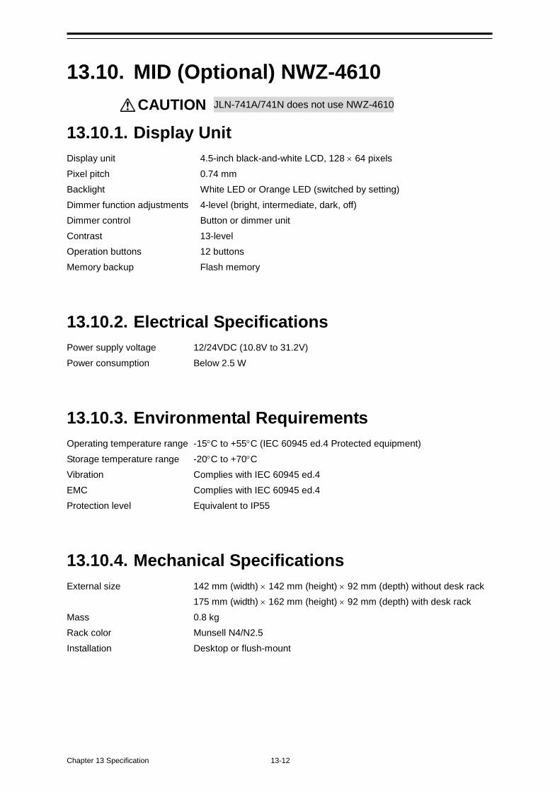
Chapter 13 Specification 13-12
13.10. MID (Optional) NWZ-4610 CAUTION JLN-741A/741N does not use NWZ-4610
13.10.1. Display Unit Display unit 4.5-inch black-and-white LCD, 128 × 64 pixels Pixel pitch 0.74 mm Backlight White LED or Orange LED (switched by setting) Dimmer function adjustments 4-level (bright, intermediate, dark, off) Dimmer control Button or dimmer unit Contrast 13-level Operation buttons 12 buttons Memory backup Flash memory
13.10.2. Electrical Specifications Power supply voltage 12/24VDC (10.8V to 31.2V) Power consumption Below 2.5 W
13.10.3. Environmental Requirements Operating temperature range -15°C to +55°C (IEC 60945 ed.4 Protected equipment) Storage temperature range -20°C to +70°C Vibration Complies with IEC 60945 ed.4 EMC Complies with IEC 60945 ed.4 Protection level Equivalent to IP55
13.10.4. Mechanical Specifications External size 142 mm (width) × 142 mm (height) × 92 mm (depth) without desk rack 175 mm (width) × 162 mm (height) × 92 mm (depth) with desk rack Mass 0.8 kg Rack color Munsell N4/N2.5 Installation Desktop or flush-mount
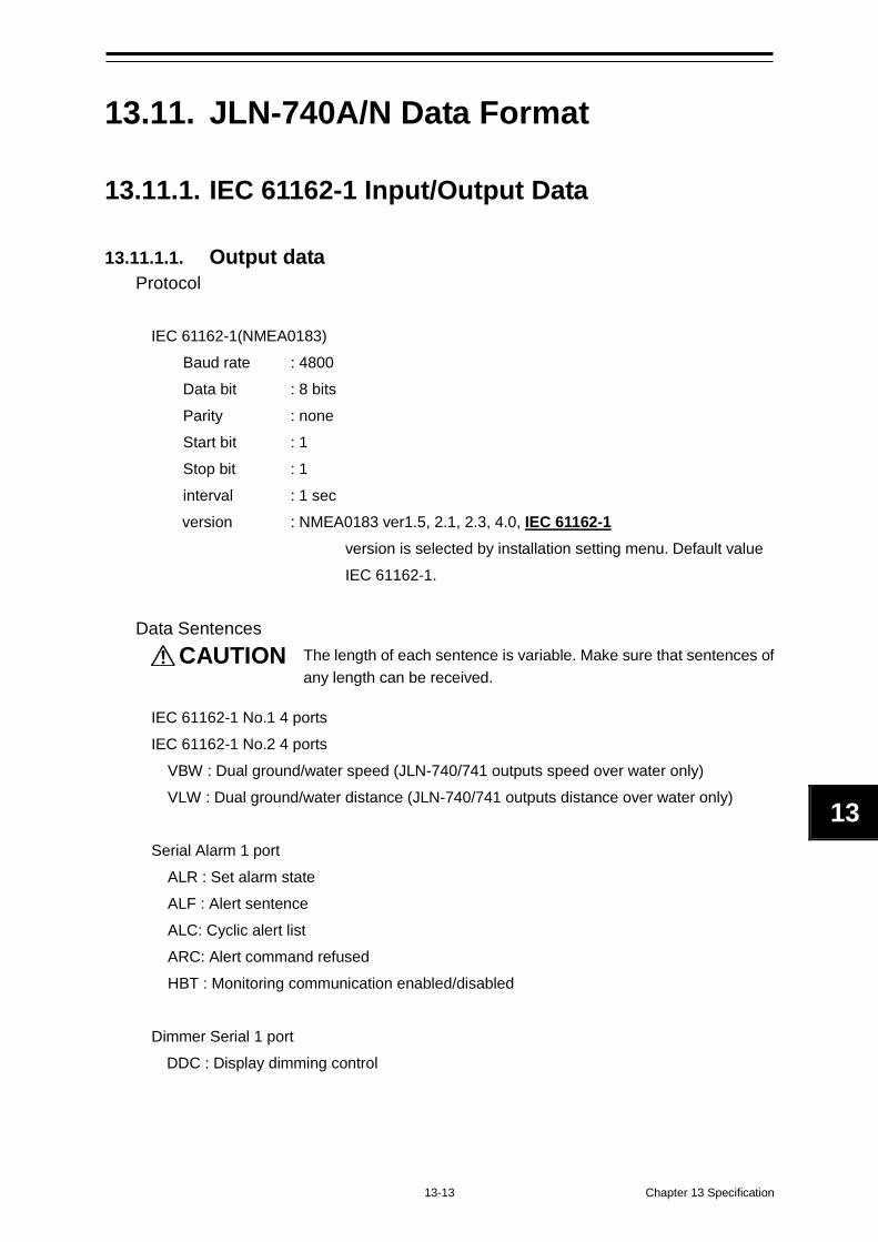
13-13 Chapter 13 Specification
1
13
1
13.11. JLN-740A/N Data Format
13.11.1. IEC 61162-1 Input/Output Data
13.11.1.1. Output data Protocol
IEC 61162-1(NMEA0183)
Baud rate : 4800 Data bit : 8 bits Parity : none Start bit : 1 Stop bit : 1 interval : 1 sec version : NMEA0183 ver1.5, 2.1, 2.3, 4.0, IEC 61162-1
version is selected by installation setting menu. Default value IEC 61162-1.
Data Sentences
CAUTION The length of each sentence is variable. Make sure that sentences of any length can be received.
IEC 61162-1 No.1 4 ports IEC 61162-1 No.2 4 ports
VBW : Dual ground/water speed (JLN-740/741 outputs speed over water only) VLW : Dual ground/water distance (JLN-740/741 outputs distance over water only)
Serial Alarm 1 port
ALR : Set alarm state ALF : Alert sentence ALC: Cyclic alert list ARC: Alert command refused HBT : Monitoring communication enabled/disabled
Dimmer Serial 1 port
DDC : Display dimming control
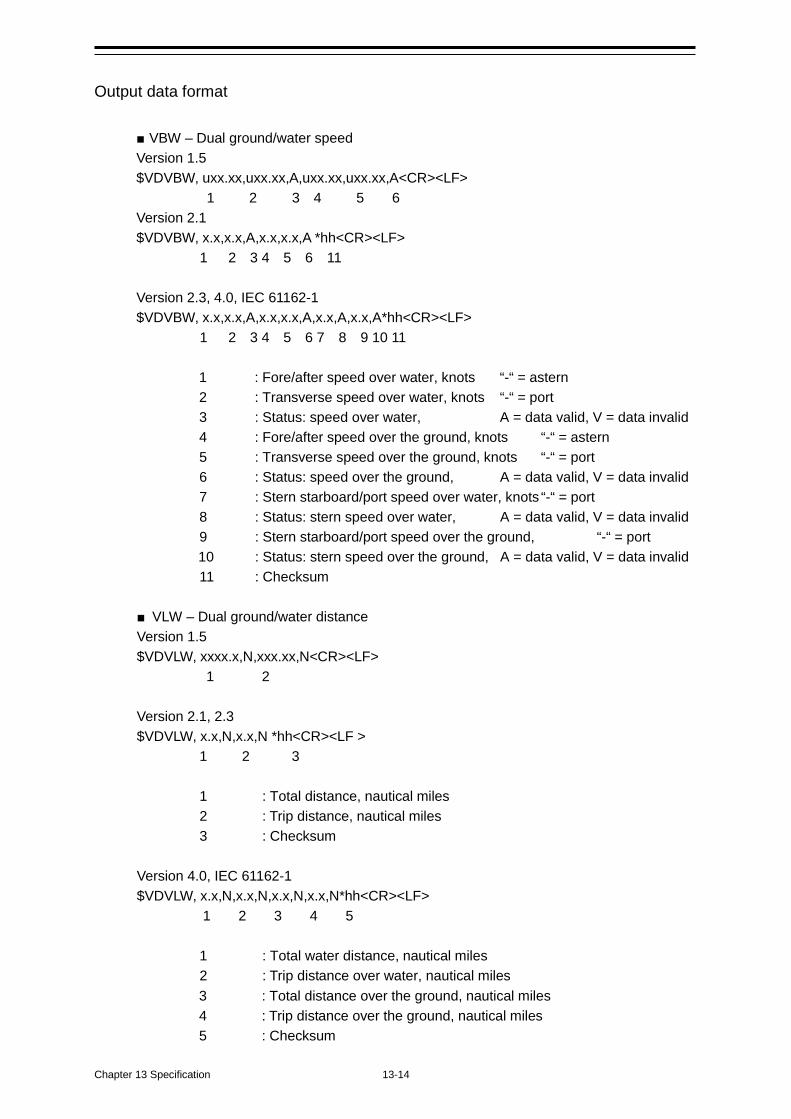
Chapter 13 Specification 13-14
Output data format
■ VBW – Dual ground/water speed Version 1.5 $VDVBW, uxx.xx,uxx.xx,A,uxx.xx,uxx.xx,A<CR><LF>
1 2 3 4 5 6 Version 2.1 $VDVBW, x.x,x.x,A,x.x,x.x,A *hh<CR><LF>
1 2 3 4 5 6 11
Version 2.3, 4.0, IEC 61162-1 $VDVBW, x.x,x.x,A,x.x,x.x,A,x.x,A,x.x,A*hh<CR><LF>
1 2 3 4 5 6 7 8 9 10 11
1 : Fore/after speed over water, knots “-“ = astern 2 : Transverse speed over water, knots “-“ = port 3 : Status: speed over water, A = data valid, V = data invalid 4 : Fore/after speed over the ground, knots “-“ = astern 5 : Transverse speed over the ground, knots “-“ = port 6 : Status: speed over the ground, A = data valid, V = data invalid 7 : Stern starboard/port speed over water, knots “-“ = port 8 : Status: stern speed over water, A = data valid, V = data invalid 9 : Stern starboard/port speed over the ground, “-“ = port 10 : Status: stern speed over the ground, A = data valid, V = data invalid 11 : Checksum
■ VLW – Dual ground/water distance Version 1.5 $VDVLW, xxxx.x,N,xxx.xx,N<CR><LF>
1 2
Version 2.1, 2.3 $VDVLW, x.x,N,x.x,N *hh<CR><LF >
1 2 3 1 : Total distance, nautical miles 2 : Trip distance, nautical miles 3 : Checksum
Version 4.0, IEC 61162-1 $VDVLW, x.x,N,x.x,N,x.x,N,x.x,N*hh<CR><LF>
1 2 3 4 5
1 : Total water distance, nautical miles 2 : Trip distance over water, nautical miles 3 : Total distance over the ground, nautical miles 4 : Trip distance over the ground, nautical miles 5 : Checksum
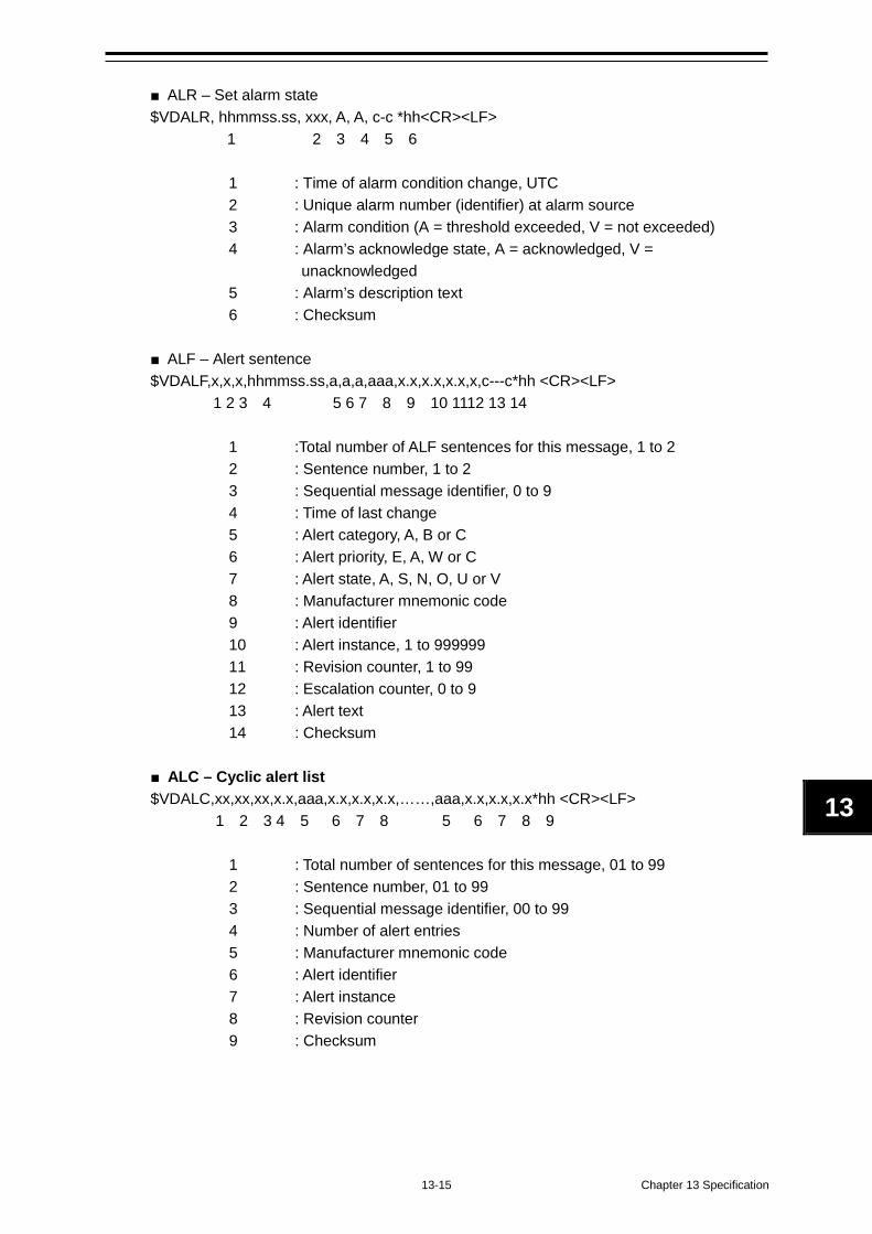
13-15 Chapter 13 Specification
1
13
1
■ ALR – Set alarm state $VDALR, hhmmss.ss, xxx, A, A, c-c *hh<CR><LF>
1 2 3 4 5 6 1 : Time of alarm condition change, UTC 2 : Unique alarm number (identifier) at alarm source 3 : Alarm condition (A = threshold exceeded, V = not exceeded) 4 : Alarm’s acknowledge state, A = acknowledged, V =
unacknowledged 5 : Alarm’s description text 6 : Checksum
■ ALF – Alert sentence $VDALF,x,x,x,hhmmss.ss,a,a,a,aaa,x.x,x.x,x.x,x,c---c*hh <CR><LF>
1 2 3 4 5 6 7 8 9 10 1112 13 14
1 :Total number of ALF sentences for this message, 1 to 2 2 : Sentence number, 1 to 2 3 : Sequential message identifier, 0 to 9 4 : Time of last change 5 : Alert category, A, B or C 6 : Alert priority, E, A, W or C 7 : Alert state, A, S, N, O, U or V 8 : Manufacturer mnemonic code 9 : Alert identifier 10 : Alert instance, 1 to 999999 11 : Revision counter, 1 to 99 12 : Escalation counter, 0 to 9 13 : Alert text 14 : Checksum
■ ALC – Cyclic alert list $VDALC,xx,xx,xx,x.x,aaa,x.x,x.x,x.x,……,aaa,x.x,x.x,x.x*hh <CR><LF>
1 2 3 4 5 6 7 8 5 6 7 8 9
1 : Total number of sentences for this message, 01 to 99 2 : Sentence number, 01 to 99 3 : Sequential message identifier, 00 to 99 4 : Number of alert entries 5 : Manufacturer mnemonic code 6 : Alert identifier 7 : Alert instance 8 : Revision counter 9 : Checksum
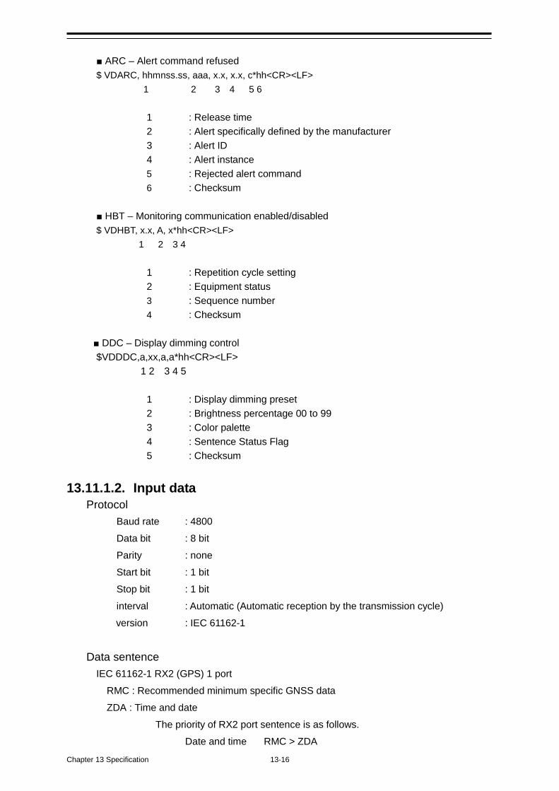
Chapter 13 Specification 13-16
■ ARC – Alert command refused $ VDARC, hhmnss.ss, aaa, x.x, x.x, c*hh<CR><LF> 1 2 3 4 5 6
1 : Release time 2 : Alert specifically defined by the manufacturer 3 : Alert ID 4 : Alert instance 5 : Rejected alert command 6 : Checksum
■ HBT – Monitoring communication enabled/disabled $ VDHBT, x.x, A, x*hh<CR><LF> 1 2 3 4
1 : Repetition cycle setting 2 : Equipment status 3 : Sequence number 4 : Checksum
■ DDC – Display dimming control $VDDDC,a,xx,a,a*hh<CR><LF> 1 2 3 4 5
1 : Display dimming preset 2 : Brightness percentage 00 to 99 3 : Color palette 4 : Sentence Status Flag 5 : Checksum
13.11.1.2. Input data Protocol
Baud rate : 4800 Data bit : 8 bit Parity : none Start bit : 1 bit Stop bit : 1 bit interval : Automatic (Automatic reception by the transmission cycle) version : IEC 61162-1
Data sentence IEC 61162-1 RX2 (GPS) 1 port
RMC : Recommended minimum specific GNSS data ZDA : Time and date
The priority of RX2 port sentence is as follows. Date and time RMC > ZDA
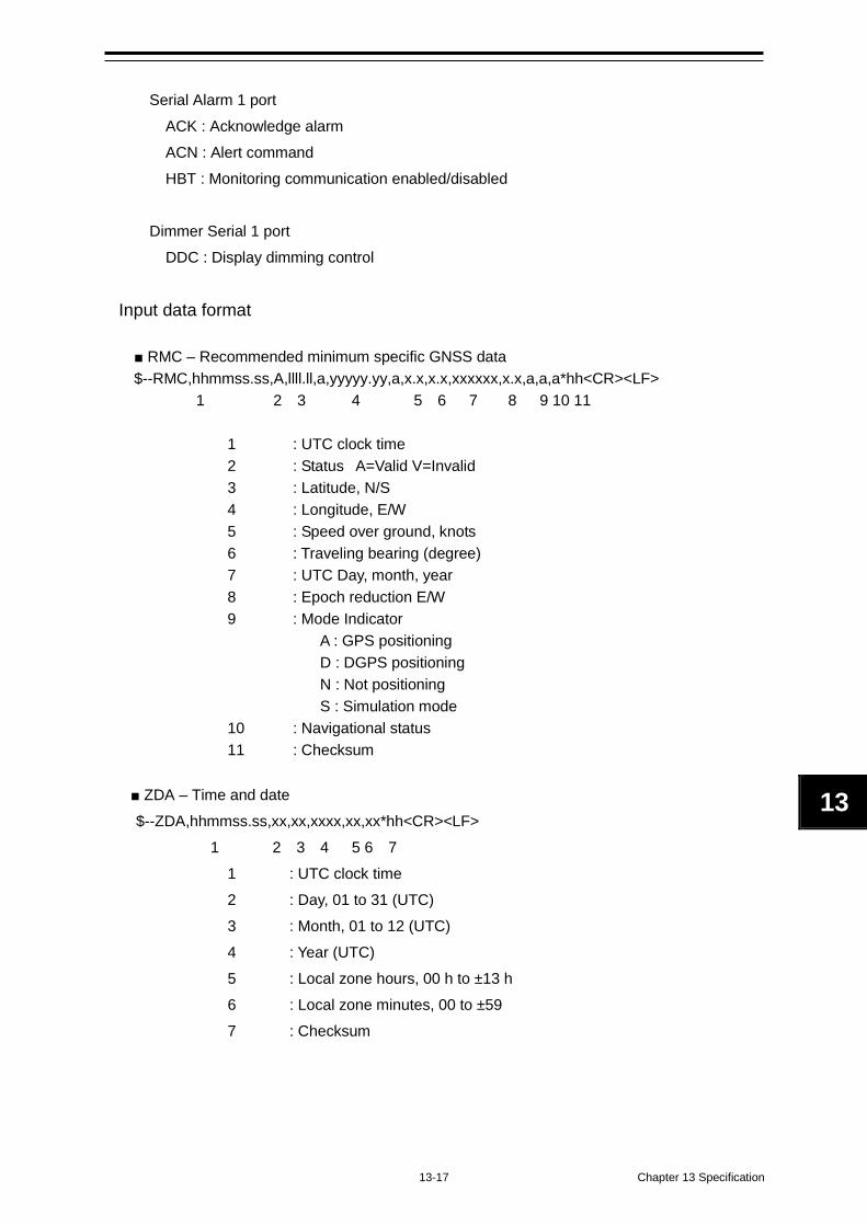
13-17 Chapter 13 Specification
1
13
1
Serial Alarm 1 port
ACK : Acknowledge alarm ACN : Alert command HBT : Monitoring communication enabled/disabled
Dimmer Serial 1 port
DDC : Display dimming control
Input data format
■ RMC – Recommended minimum specific GNSS data $--RMC,hhmmss.ss,A,llll.ll,a,yyyyy.yy,a,x.x,x.x,xxxxxx,x.x,a,a,a*hh<CR><LF>
1 2 3 4 5 6 7 8 9 10 11
1 : UTC clock time 2 : Status A=Valid V=Invalid 3 : Latitude, N/S 4 : Longitude, E/W 5 : Speed over ground, knots 6 : Traveling bearing (degree) 7 : UTC Day, month, year 8 : Epoch reduction E/W 9 : Mode Indicator
A : GPS positioning D : DGPS positioning N : Not positioning S : Simulation mode
10 : Navigational status 11 : Checksum
■ ZDA – Time and date $--ZDA,hhmmss.ss,xx,xx,xxxx,xx,xx*hh<CR><LF> 1 2 3 4 5 6 7
1 : UTC clock time 2 : Day, 01 to 31 (UTC) 3 : Month, 01 to 12 (UTC) 4 : Year (UTC) 5 : Local zone hours, 00 h to ±13 h 6 : Local zone minutes, 00 to ±59 7 : Checksum
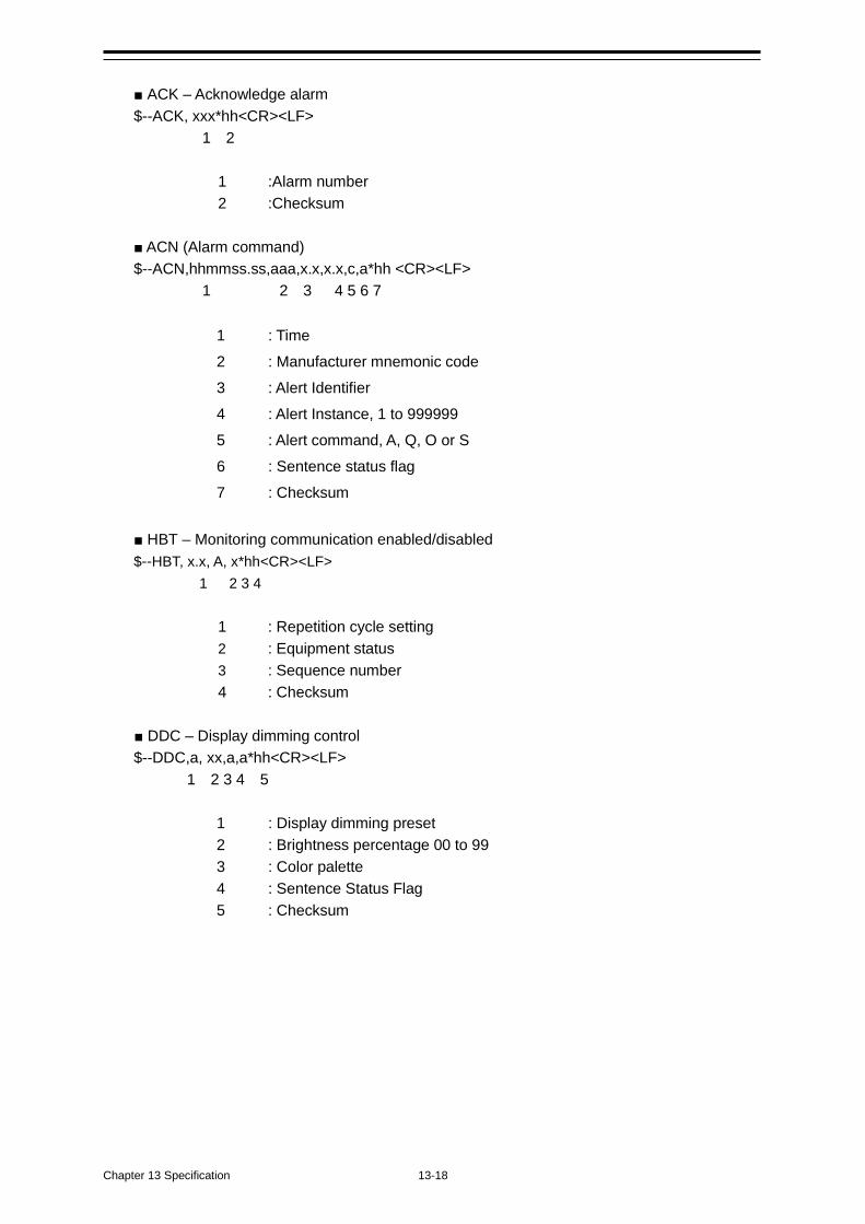
Chapter 13 Specification 13-18
■ ACK – Acknowledge alarm $--ACK, xxx*hh<CR><LF> 1 2
1 :Alarm number 2 :Checksum
■ ACN (Alarm command) $--ACN,hhmmss.ss,aaa,x.x,x.x,c,a*hh <CR><LF> 1 2 3 4 5 6 7
1 : Time 2 : Manufacturer mnemonic code 3 : Alert Identifier 4 : Alert Instance, 1 to 999999 5 : Alert command, A, Q, O or S 6 : Sentence status flag 7 : Checksum
■ HBT – Monitoring communication enabled/disabled $--HBT, x.x, A, x*hh<CR><LF> 1 2 3 4
1 : Repetition cycle setting 2 : Equipment status 3 : Sequence number 4 : Checksum
■ DDC – Display dimming control $--DDC,a, xx,a,a*hh<CR><LF> 1 2 3 4 5
1 : Display dimming preset 2 : Brightness percentage 00 to 99 3 : Color palette 4 : Sentence Status Flag 5 : Checksum
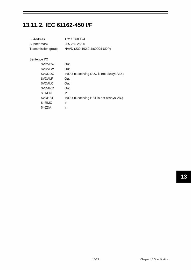
13-19 Chapter 13 Specification
1
13
1
13.11.2. IEC 61162-450 I/F
IP Address 172.16.60.124 Subnet mask 255.255.255.0 Transmission group NAVD (239.192.0.4:60004 UDP)
Sentence I/O $VDVBW Out $VDVLW Out $VDDDC In/Out (Receiving DDC is not always VD.) $VDALF Out $VDALC Out $VDARC Out $--ACN In $VDHBT In/Out (Receiving HBT is not always VD.) $--RMC In $--ZDA In
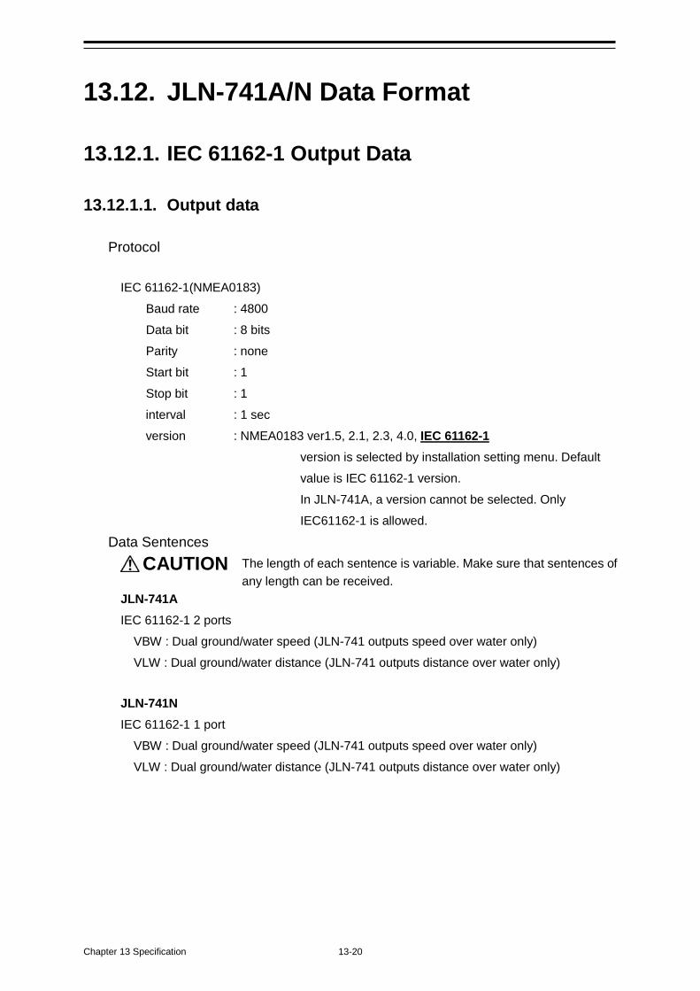
Chapter 13 Specification 13-20
13.12. JLN-741A/N Data Format
13.12.1. IEC 61162-1 Output Data
13.12.1.1. Output data Protocol
IEC 61162-1(NMEA0183)
Baud rate : 4800 Data bit : 8 bits Parity : none Start bit : 1 Stop bit : 1 interval : 1 sec version : NMEA0183 ver1.5, 2.1, 2.3, 4.0, IEC 61162-1
version is selected by installation setting menu. Default value is IEC 61162-1 version. In JLN-741A, a version cannot be selected. Only IEC61162-1 is allowed.
Data Sentences CAUTION The length of each sentence is variable. Make sure that sentences of
any length can be received. JLN-741A IEC 61162-1 2 ports
VBW : Dual ground/water speed (JLN-741 outputs speed over water only) VLW : Dual ground/water distance (JLN-741 outputs distance over water only)
JLN-741N IEC 61162-1 1 port
VBW : Dual ground/water speed (JLN-741 outputs speed over water only) VLW : Dual ground/water distance (JLN-741 outputs distance over water only)
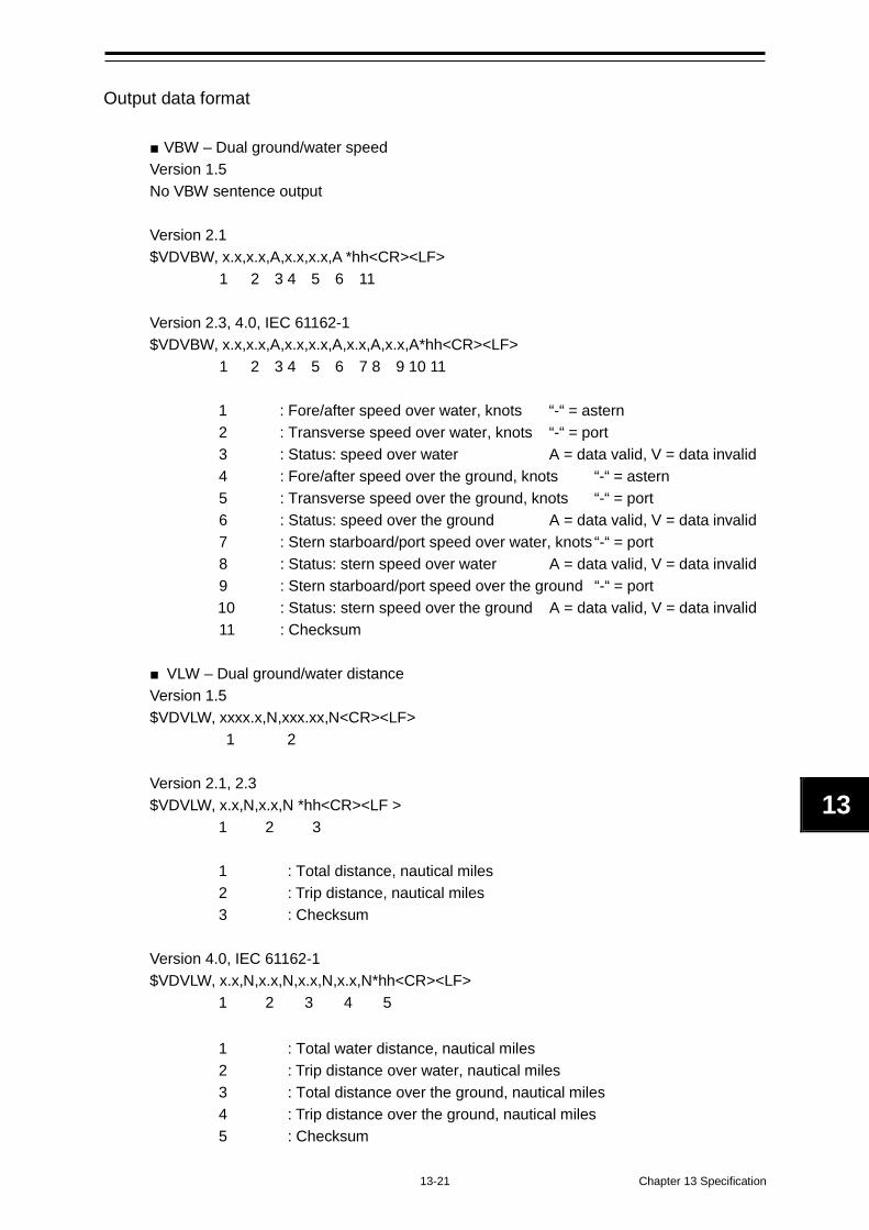
13-21 Chapter 13 Specification
1
13
1
Output data format
■ VBW – Dual ground/water speed Version 1.5 No VBW sentence output
Version 2.1 $VDVBW, x.x,x.x,A,x.x,x.x,A *hh<CR><LF>
1 2 3 4 5 6 11
Version 2.3, 4.0, IEC 61162-1 $VDVBW, x.x,x.x,A,x.x,x.x,A,x.x,A,x.x,A*hh<CR><LF>
1 2 3 4 5 6 7 8 9 10 11
1 : Fore/after speed over water, knots “-“ = astern 2 : Transverse speed over water, knots “-“ = port 3 : Status: speed over water A = data valid, V = data invalid 4 : Fore/after speed over the ground, knots “-“ = astern 5 : Transverse speed over the ground, knots “-“ = port 6 : Status: speed over the ground A = data valid, V = data invalid 7 : Stern starboard/port speed over water, knots “-“ = port 8 : Status: stern speed over water A = data valid, V = data invalid 9 : Stern starboard/port speed over the ground “-“ = port 10 : Status: stern speed over the ground A = data valid, V = data invalid 11 : Checksum
■ VLW – Dual ground/water distance Version 1.5 $VDVLW, xxxx.x,N,xxx.xx,N<CR><LF>
1 2
Version 2.1, 2.3 $VDVLW, x.x,N,x.x,N *hh<CR><LF >
1 2 3
1 : Total distance, nautical miles 2 : Trip distance, nautical miles 3 : Checksum
Version 4.0, IEC 61162-1 $VDVLW, x.x,N,x.x,N,x.x,N,x.x,N*hh<CR><LF>
1 2 3 4 5
1 : Total water distance, nautical miles 2 : Trip distance over water, nautical miles 3 : Total distance over the ground, nautical miles 4 : Trip distance over the ground, nautical miles 5 : Checksum
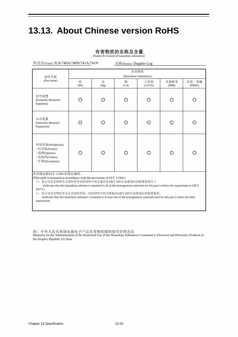
Chapter 13 Specification 13-22
13.13. About Chinese version RoHS
形式名(Type): JLN-740A/740N/741A/741N 名称(Name): Doppler Log
铅 汞 镉 六价铬 多溴联苯 多溴二苯醚(Pb) (Hg) (Cd) (Cr(Ⅵ)) (PBB) (PBDE)
室外装置(Extanally MounrtedEqipment)
○ ○ ○ ○ ○ ○
室内装置(Internally MountedEquipment)
○ ○ ○ ○ ○ ○
外部设备(Peripherals) ・打印机(Printer) ・选择(Options) ・电线类(Cables) ・手册(Documents)
○ ○ ○ ○ ○ ○
本表格依据SJ/T 11364 的规定编制。
(This table is prepared in accordance with the provisions of SJ/T 11364.)
有害物质的名称及含量(Names & Content of hazardous substances)
Measures for the Administration of the Restricted Use of the Hazardous Substances Contained in Electrical and Electronic Products ofthe People's Republic of China
RE: 中华人民共和国电器电子产品有害物质限制使用管理办法
○:表示该有害物质在该部件所有均质材料中的含量均在GB/T 26572 标准规定的限量要求以下。
(Indicates that this hazardous substance contained in all of the homogeneous materials for this part is below the requirement in GB/T26572.)×:表示该有害物质至少在该部件的某一均质材料中的含量超出GB/T 26572 标准规定的限量要求。
(Indicates that this hazardous substance contained in at least one of the homogeneous materials used for this part is above the limitrequirement
部件名称(Part name)
有害物质
(Hazardous Substances)
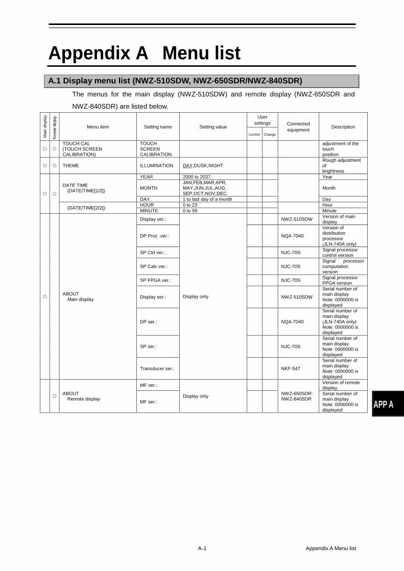
A-1 Appendix A Menu list
APP A
Appendix A Menu list A.1 Display menu list (NWZ-510SDW, NWZ-650SDR/NWZ-840SDR)
The menus for the main display (NWZ-510SDW) and remote display (NWZ-650SDR and
NWZ-840SDR) are listed below.
Mai
n di
spla
y
Remo
te dis
play
Menu item Setting name Setting value
User settings Connected
equipment Description Current Change
TOUCH CAL (TOUCH SCREEN CALIBRATION)
TOUCH SCREEN CALIBRATION
adjustment of the touch position
THEME ILLUMINATION DAY,DUSK,NIGHT Rough adjustment of brightness
DATE TIME (DATE/TIME[1/2])
YEAR 2000 to 2037
Year
MONTH JAN,FEB,MAR,APR, MAY,JUN,JUL,AUG, SEP,OCT,NOV,DEC
Month
DAY 1 to last day of a month Day
(DATE/TIME[2/2]) HOUR 0 to 23 Hour
MINUTE 0 to 59 Minute
ABOUT Main display
Display ver.:
Display only
NWZ-510SDW Version of main display
DP Proc .ver.: NQA-7040
Version of distribution processor (JLN-740A only)
SP Ctrl ver.: NJC-70S Signal processor control version
SP Calc ver.: NJC-70S Signal processor computation version
SP FPGA ver.: NJC-70S Signal processor FPGA version
Display ser.: NWZ-510SDW
Serial number of main display Note: 0000000 is displayed
DP ser.: NQA-7040
Serial number of main display (JLN-740A only) Note: 0000000 is displayed
SP ser.: NJC-70S
Serial number of main display Note: 0000000 is displayed
Transducer ser.: NKF-547
Serial number of main display Note: 0000000 is displayed
ABOUT Remote display
MF ver.:
Display only
NWZ-650SDR NWZ-840SDR
Version of remote display
MF ser.: Serial number of main display Note: 0000000 is displayed
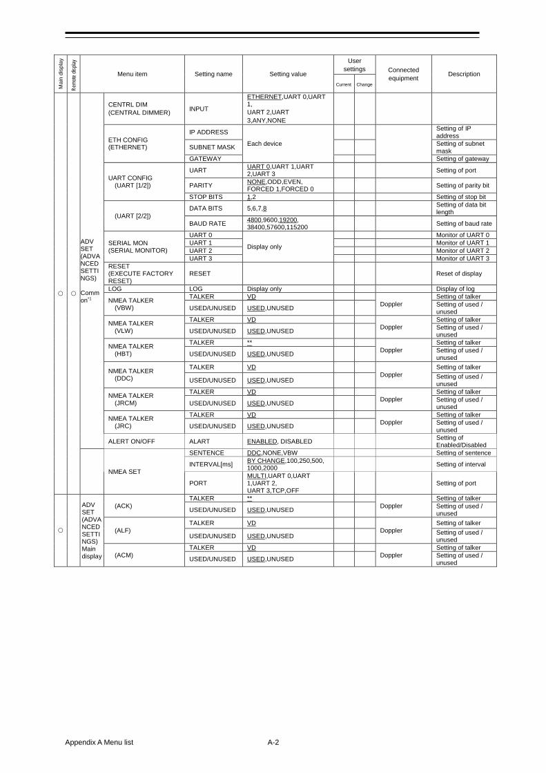
Appendix A Menu list A-2
Mai
n di
spla
y
Remo
te dis
play
Menu item Setting name Setting value
User settings Connected
equipment Description Current Change
ADV SET (ADVANCED SETTINGS) Common*1
CENTRL DIM (CENTRAL DIMMER) INPUT
ETHERNET,UART 0,UART 1, UART 2,UART 3,ANY,NONE
ETH CONFIG (ETHERNET)
IP ADDRESS
Each device
Setting of IP address
SUBNET MASK Setting of subnet mask
GATEWAY Setting of gateway
UART CONFIG (UART [1/2])
UART UART 0,UART 1,UART 2,UART 3
Setting of port
PARITY NONE,ODD,EVEN, FORCED 1,FORCED 0
Setting of parity bit
STOP BITS 1,2 Setting of stop bit
(UART [2/2]) DATA BITS 5,6,7,8 Setting of data bit
length
BAUD RATE 4800,9600,19200, 38400,57600,115200
Setting of baud rate
SERIAL MON (SERIAL MONITOR)
UART 0
Display only
Monitor of UART 0 UART 1 Monitor of UART 1 UART 2 Monitor of UART 2 UART 3 Monitor of UART 3
RESET (EXECUTE FACTORY RESET)
RESET Reset of display
LOG LOG Display only Display of log
NMEA TALKER (VBW)
TALKER VD Doppler
Setting of talker
USED/UNUSED USED,UNUSED Setting of used / unused
NMEA TALKER (VLW)
TALKER VD Doppler
Setting of talker
USED/UNUSED USED,UNUSED Setting of used / unused
NMEA TALKER (HBT)
TALKER ** Doppler
Setting of talker
USED/UNUSED USED,UNUSED Setting of used / unused
NMEA TALKER (DDC)
TALKER VD Doppler
Setting of talker
USED/UNUSED USED,UNUSED Setting of used / unused
NMEA TALKER (JRCM)
TALKER VD Doppler
Setting of talker
USED/UNUSED USED,UNUSED Setting of used / unused
NMEA TALKER (JRC)
TALKER VD Doppler
Setting of talker
USED/UNUSED USED,UNUSED Setting of used / unused
ALERT ON/OFF ALART ENABLED, DISABLED Setting of Enabled/Disabled
NMEA SET
SENTENCE DDC,NONE,VBW Setting of sentence
INTERVAL[ms] BY CHANGE,100,250,500, 1000,2000
Setting of interval
PORT MULTI,UART 0,UART 1,UART 2, UART 3,TCP,OFF
Setting of port
ADV SET (ADVANCED SETTINGS) Main display
(ACK) TALKER **
Doppler Setting of talker
USED/UNUSED USED,UNUSED Setting of used / unused
(ALF) TALKER VD
Doppler Setting of talker
USED/UNUSED USED,UNUSED Setting of used / unused
(ACM) TALKER VD
Doppler Setting of talker
USED/UNUSED USED,UNUSED Setting of used / unused
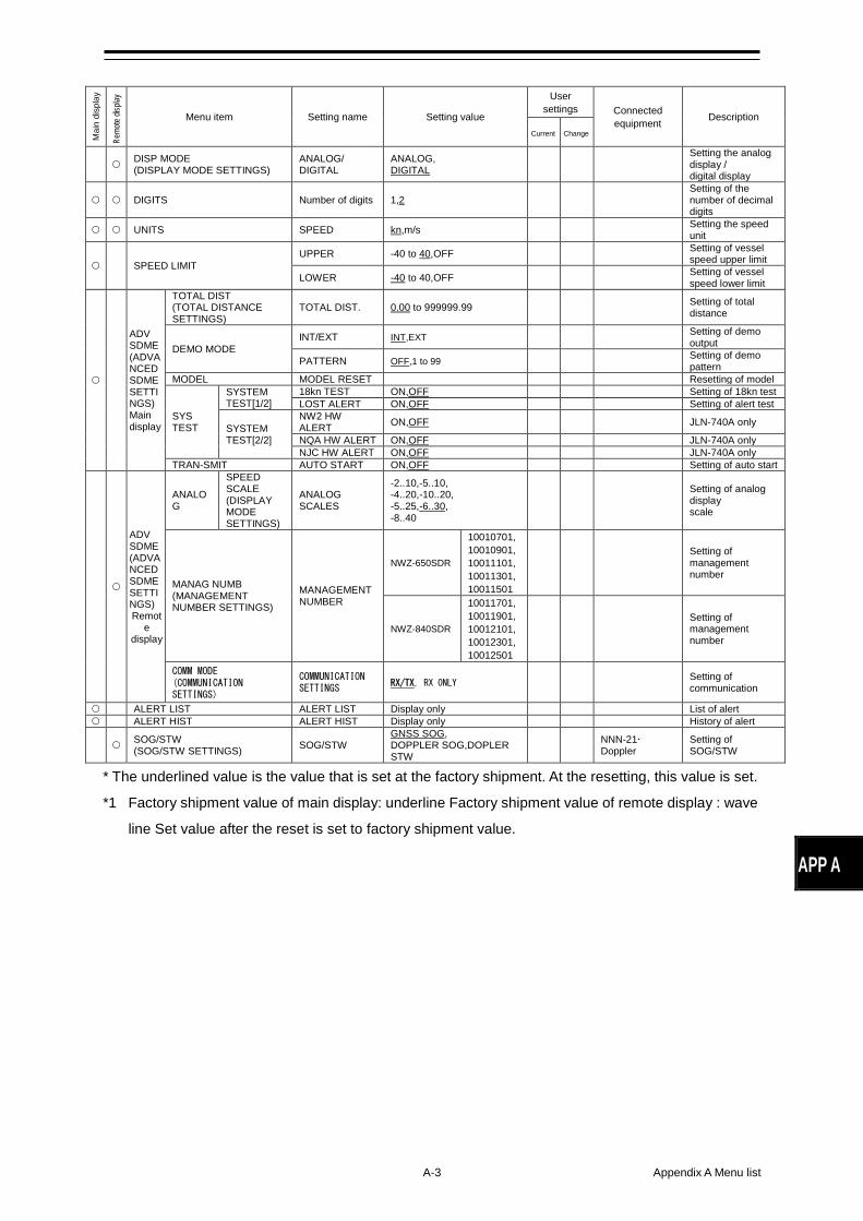
A-3 Appendix A Menu list
APP A
* The underlined value is the value that is set at the factory shipment. At the resetting, this value is set.
*1 Factory shipment value of main display: underline Factory shipment value of remote display : wave
line Set value after the reset is set to factory shipment value.
Mai
n di
spla
y
Remo
te dis
play
Menu item Setting name Setting value
User settings Connected
equipment Description Current Change
DISP MODE (DISPLAY MODE SETTINGS)
ANALOG/ DIGITAL
ANALOG, DIGITAL
Setting the analog display / digital display
DIGITS Number of digits 1,2 Setting of the number of decimal digits
UNITS SPEED kn,m/s Setting the speed unit
SPEED LIMIT UPPER -40 to 40,OFF Setting of vessel
speed upper limit
LOWER -40 to 40,OFF Setting of vessel speed lower limit
ADV SDME (ADVANCED SDME SETTINGS) Main display
TOTAL DIST (TOTAL DISTANCE SETTINGS)
TOTAL DIST. 0.00 to 999999.99 Setting of total distance
DEMO MODE INT/EXT INT,EXT Setting of demo
output
PATTERN OFF,1 to 99 Setting of demo pattern
MODEL MODEL RESET Resetting of model
SYS TEST
SYSTEM TEST[1/2]
18kn TEST ON,OFF Setting of 18kn test LOST ALERT ON,OFF Setting of alert test
SYSTEM TEST[2/2]
NW2 HW ALERT ON,OFF JLN-740A only
NQA HW ALERT ON,OFF JLN-740A only NJC HW ALERT ON,OFF JLN-740A only
TRAN-SMIT AUTO START ON,OFF Setting of auto start
ADV SDME (ADVANCED SDME SETTINGS) Remot
e display
ANALOG
SPEED SCALE (DISPLAY MODE SETTINGS)
ANALOG SCALES
-2..10,-5..10, -4..20,-10..20, -5..25,-6..30, -8..40
Setting of analog display scale
MANAG NUMB (MANAGEMENT NUMBER SETTINGS)
MANAGEMENT NUMBER
NWZ-650SDR
10010701, 10010901, 10011101, 10011301, 10011501
Setting of management number
NWZ-840SDR
10011701, 10011901, 10012101, 10012301, 10012501
Setting of management number
COMM MODE (COMMUNICATION SETTINGS)
COMMUNICATION SETTINGS RX/TX, RX ONLY Setting of
communication
ALERT LIST ALERT LIST Display only List of alert ALERT HIST ALERT HIST Display only History of alert
SOG/STW (SOG/STW SETTINGS) SOG/STW
GNSS SOG, DOPPLER SOG,DOPLER STW
NNN-21 Doppler
Setting of SOG/STW
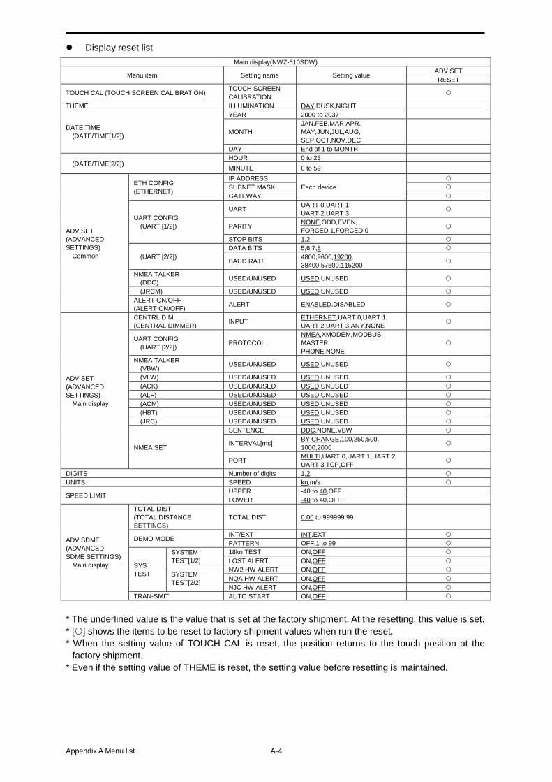
Appendix A Menu list A-4
Display reset list
* The underlined value is the value that is set at the factory shipment. At the resetting, this value is set. * [] shows the items to be reset to factory shipment values when run the reset. * When the setting value of TOUCH CAL is reset, the position returns to the touch position at the
factory shipment. * Even if the setting value of THEME is reset, the setting value before resetting is maintained.
Main display(NWZ-510SDW)
Menu item Setting name Setting value ADV SET RESET
TOUCH CAL (TOUCH SCREEN CALIBRATION) TOUCH SCREEN CALIBRATION
THEME ILLUMINATION DAY,DUSK,NIGHT
DATE TIME (DATE/TIME[1/2])
YEAR 2000 to 2037
MONTH JAN,FEB,MAR,APR, MAY,JUN,JUL,AUG, SEP,OCT,NOV,DEC
DAY End of 1 to MONTH
(DATE/TIME[2/2]) HOUR 0 to 23 MINUTE 0 to 59
ADV SET (ADVANCED SETTINGS) Common
ETH CONFIG (ETHERNET)
IP ADDRESS Each device
SUBNET MASK GATEWAY
UART CONFIG (UART [1/2])
UART UART 0,UART 1, UART 2,UART 3
PARITY NONE,ODD,EVEN, FORCED 1,FORCED 0
STOP BITS 1,2
(UART [2/2]) DATA BITS 5,6,7,8
BAUD RATE 4800,9600,19200, 38400,57600,115200
NMEA TALKER (DDC) USED/UNUSED USED,UNUSED
(JRCM) USED/UNUSED USED,UNUSED ALERT ON/OFF (ALERT ON/OFF) ALERT ENABLED,DISABLED
ADV SET (ADVANCED SETTINGS) Main display
CENTRL DIM (CENTRAL DIMMER) INPUT ETHERNET,UART 0,UART 1,
UART 2,UART 3,ANY,NONE
UART CONFIG (UART [2/2]) PROTOCOL
NMEA,XMODEM,MODBUS MASTER, PHONE,NONE
NMEA TALKER (VBW) USED/UNUSED USED,UNUSED
(VLW) USED/UNUSED USED,UNUSED (ACK) USED/UNUSED USED,UNUSED (ALF) USED/UNUSED USED,UNUSED (ACM) USED/UNUSED USED,UNUSED (HBT) USED/UNUSED USED,UNUSED (JRC) USED/UNUSED USED,UNUSED
NMEA SET
SENTENCE DDC,NONE,VBW
INTERVAL[ms] BY CHANGE,100,250,500, 1000,2000
PORT MULTI,UART 0,UART 1,UART 2, UART 3,TCP,OFF
DIGITS Number of digits 1,2 UNITS SPEED kn,m/s
SPEED LIMIT UPPER -40 to 40,OFF LOWER -40 to 40,OFF
ADV SDME (ADVANCED SDME SETTINGS) Main display
TOTAL DIST (TOTAL DISTANCE SETTINGS)
TOTAL DIST. 0.00 to 999999.99
DEMO MODE INT/EXT INT,EXT PATTERN OFF,1 to 99
SYS TEST
SYSTEM TEST[1/2]
18kn TEST ON,OFF LOST ALERT ON,OFF
SYSTEM TEST[2/2]
NW2 HW ALERT ON,OFF NQA HW ALERT ON,OFF NJC HW ALERT ON,OFF
TRAN-SMIT AUTO START ON,OFF
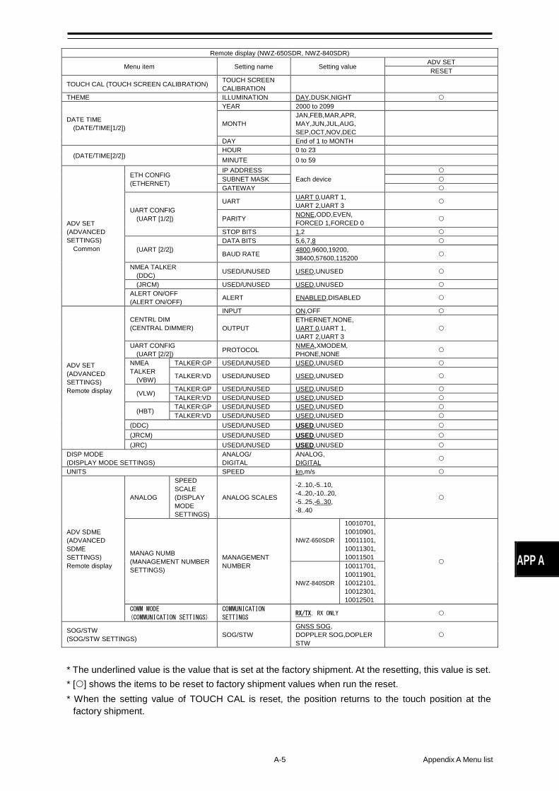
A-5 Appendix A Menu list
APP A
* The underlined value is the value that is set at the factory shipment. At the resetting, this value is set. * [] shows the items to be reset to factory shipment values when run the reset. * When the setting value of TOUCH CAL is reset, the position returns to the touch position at the
factory shipment.
Remote display (NWZ-650SDR, NWZ-840SDR)
Menu item Setting name Setting value ADV SET RESET
TOUCH CAL (TOUCH SCREEN CALIBRATION) TOUCH SCREEN CALIBRATION
THEME ILLUMINATION DAY,DUSK,NIGHT
DATE TIME (DATE/TIME[1/2])
YEAR 2000 to 2099
MONTH JAN,FEB,MAR,APR, MAY,JUN,JUL,AUG, SEP,OCT,NOV,DEC
DAY End of 1 to MONTH
(DATE/TIME[2/2]) HOUR 0 to 23 MINUTE 0 to 59
ADV SET (ADVANCED SETTINGS) Common
ETH CONFIG (ETHERNET)
IP ADDRESS Each device
SUBNET MASK GATEWAY
UART CONFIG (UART [1/2])
UART UART 0,UART 1, UART 2,UART 3
PARITY NONE,ODD,EVEN, FORCED 1,FORCED 0
STOP BITS 1,2
(UART [2/2]) DATA BITS 5,6,7,8
BAUD RATE 4800,9600,19200, 38400,57600,115200
NMEA TALKER (DDC) USED/UNUSED USED,UNUSED
(JRCM) USED/UNUSED USED,UNUSED ALERT ON/OFF (ALERT ON/OFF) ALERT ENABLED,DISABLED
ADV SET (ADVANCED SETTINGS) Remote display
CENTRL DIM (CENTRAL DIMMER)
INPUT ON,OFF
OUTPUT ETHERNET,NONE, UART 0,UART 1, UART 2,UART 3
UART CONFIG (UART [2/2]) PROTOCOL NMEA,XMODEM,
PHONE,NONE
NMEA TALKER (VBW)
TALKER:GP USED/UNUSED USED,UNUSED
TALKER:VD USED/UNUSED USED,UNUSED
(VLW) TALKER:GP USED/UNUSED USED,UNUSED TALKER:VD USED/UNUSED USED,UNUSED
(HBT) TALKER:GP USED/UNUSED USED,UNUSED TALKER:VD USED/UNUSED USED,UNUSED
(DDC) USED/UNUSED USED,UNUSED (JRCM) USED/UNUSED USED,UNUSED (JRC) USED/UNUSED USED,UNUSED
DISP MODE (DISPLAY MODE SETTINGS)
ANALOG/ DIGITAL
ANALOG, DIGITAL
UNITS SPEED kn,m/s
ADV SDME (ADVANCED SDME SETTINGS) Remote display
ANALOG
SPEED SCALE (DISPLAY MODE SETTINGS)
ANALOG SCALES
-2..10,-5..10, -4..20,-10..20, -5..25,-6..30, -8..40
MANAG NUMB (MANAGEMENT NUMBER SETTINGS)
MANAGEMENT NUMBER
NWZ-650SDR
10010701, 10010901, 10011101, 10011301, 10011501
NWZ-840SDR
10011701, 10011901, 10012101, 10012301, 10012501
COMM MODE
(COMMUNICATION SETTINGS) COMMUNICATION
SETTINGS RX/TX, RX ONLY
SOG/STW (SOG/STW SETTINGS) SOG/STW
GNSS SOG, DOPPLER SOG,DOPLER STW
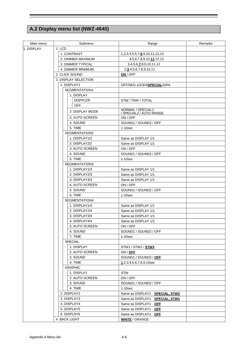
Appendix A Menu list A-6
A.2 Display menu list (NWZ-4640) Main menu Submenu Range Remarks
1. DISPLAY 1. LCD 1. CONTRAST 1,2,3,4,5,6,7,8,9,10,11,12,13 2. DIMMER MAXIMUM 4,5,6,7,8,9,10,11,12,13 3. DIMMER TYPICAL 3,4,5,6,7,8,9,10,11,12 4. DIMMER MINIMUM 2,3,4,5,6,7,8,9,10,11 2. CLICK SOUND ON / OFF 3. DISPLAY SELECTION 1. DISPLAY1 OFF/SEG.1/2/3/4/SPECIAL/GRA. SEGMENTATION1 1. DISPLAY DOPPLER STW / TRIP / TOTAL OFF 2. DISPLAY MODE NORMAL / SPECIAL1
/ SPECIAL2 / AUTO RANGE 3. AUTO SCREEN ON / OFF 4. SOUND SOUND1 / SOUND2 / OFF 5. TIME 1-10sec SEGMENTATION2 1. DISPLAY1/2 Same as DISPLAY 1/1 2. DISPLAY2/2 Same as DISPLAY 1/1 3. AUTO SCREEN ON / OFF 4. SOUND SOUND1 / SOUND2 / OFF 5. TIME 1-10sec SEGMENTATION3 1. DISPLAY1/3 Same as DISPLAY 1/1 2. DISPLAY2/3 Same as DISPLAY 1/1 3. DISPLAY3/3 Same as DISPLAY 1/1 4. AUTO SCREEN ON / OFF 5. SOUND SOUND1 / SOUND2 / OFF 6. TIME 1-10sec SEGMENTATION4 1. DISPLAY1/4 Same as DISPLAY 1/1 2. DISPLAY2/4 Same as DISPLAY 1/1 3. DISPLAY3/4 Same as DISPLAY 1/1 4. DISPLAY4/4 Same as DISPLAY 1/1 5. AUTO SCREEN ON / OFF 6. SOUND SOUND1 / SOUND2 / OFF 7. TIME 1-10sec SPECIAL 1. DISPLAY STW1 / STW2 / STW3 2. AUTO SCREEN ON / OFF 3. SOUND SOUND1 / SOUND2 / OFF 4. TIME 1,2,3,4,5,6,7,8,9,10sec GRAPHIC 1. DISPLAY STW 2. AUTO SCREEN ON / OFF 3. SOUND SOUND1 / SOUND2 / OFF 4. TIME 1-10sec 2. DISPLAY2 Same as DISPLAY1 SPECIAL, STW2 3. DISPLAY3 Same as DISPLAY1 SPECIAL, STW1 4. DISPLAY4 Same as DISPLAY1 OFF 5. DISPLAY5 Same as DISPLAY1 OFF 6. DISPLAY6 Same as DISPLAY1 OFF 4. BACK LIGHT WHITE / ORANGE
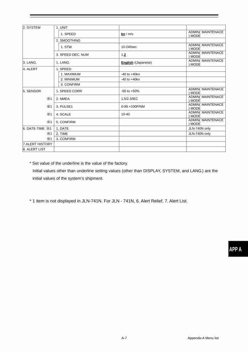
A-7 Appendix A Menu list
APP A
2. SYSTEM 1. UNIT 1. SPEED kn / m/s ADMIN( MAINTENACE
) MODE 2. SMOOTHING 1. STW 10-240sec ADMIN( MAINTENACE
) MODE 3. SPEED DEC. NUM 1,2 ADMIN( MAINTENACE
) MODE
3. LANG. 1. LANG. English /(Japanese) ADMIN( MAINTENACE) MODE
4. ALERT 1. SPEED 1. MAXIMUM -40 to +40kn 2. MINIMUM -40 to +40kn 3. CONFIRM
5. SENSOR 1. SPEED CORR -50 to +50% ADMIN( MAINTENACE) MODE
※1 2. NMEA 1.5/2.3/IEC ADMIN( MAINTENACE) MODE
※1 3. PULSE1 0-99 ×100P/NM ADMIN( MAINTENACE) MODE
※1 4. SCALE 10-40 ADMIN( MAINTENACE) MODE
※1 5. CONFIRM ADMIN( MAINTENACE) MODE
6. DATE-TIME ※1 1. DATE JLN-740N only ※1 2. TIME JLN-740N only ※1 3. CONFIRM
7.ALERT HISTORY
8. ALERT LIST
* Set value of the underline is the value of the factory.
Initial values other than underline setting values (other than DISPLAY, SYSTEM, and LANG.) are the
initial values of the system's shipment.
* 1 item is not displayed in JLN-741N. For JLN - 741N, 6. Alert Relief, 7. Alert List.
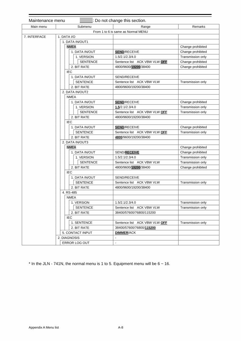
Appendix A Menu list A-8
Maintenance menu ___: Do not change this section. Main menu Submenu Range Remarks
From 1 to 6 is same as Normal MENU 7. INTERFACE 1. DATA I/O 1. DATA IN/OUT1 NMEA Change prohibited 1. DATA IN/OUT SEND/RECEIVE Change prohibited 1. VERSION 1.5/2.1/2.3/4.0 Transmission only SENTENCE Sentence list ACK VBW VLW OFF Change prohibited 2. BIT RATE 4800/9600/19200/38400 Change prohibited IEC 1. DATA IN/OUT SEND/RECEIVE SENTENCE Sentence list ACK VBW VLW Transmission only 2. BIT RATE 4800/9600/19200/38400 2. DATA IN/OUT2 NMEA 1. DATA IN/OUT SEND/RECEIVE Change prohibited 1. VERSION 1.5/2.1/2.3/4.0 Transmission only SENTENCE Sentence list ACK VBW VLW OFF Transmission only 2. BIT RATE 4800/9600/19200/38400 IEC 1. DATA IN/OUT SEND/RECEIVE Change prohibited SENTENCE Sentence list ACK VBW VLW OFF Transmission only 2. BIT RATE 4800/9600/19200/38400 2. DATA IN/OUT3 NMEA Change prohibited 1. DATA IN/OUT SEND/RECEIVE Change prohibited 1. VERSION 1.5/2.1/2.3/4.0 Transmission only SENTENCE Sentence list ACK VBW VLW Transmission only 2. BIT RATE 4800/9600/19200/38400 Change prohibited IEC 1. DATA IN/OUT SEND/RECEIVE SENTENCE Sentence list ACK VBW VLW Transmission only 2. BIT RATE 4800/9600/19200/38400 4. RS-485 NMEA 1. VERSION 1.5/2.1/2.3/4.0 Transmission only SENTENCE Sentence list ACK VBW VLW Transmission only 2. BIT RATE 38400/57600/76800/115200 IEC 1. SENTENCE Sentence list ACK VBW VLW OFF Transmission only 2. BIT RATE 38400/57600/76800/115200 5. CONTACT INPUT DIMMER/ACK 2. DIAGNOSIS - ERROR LOG OUT -
* In the JLN - 741N, the normal menu is 1 to 5. Equipment menu will be 6 ~ 16.
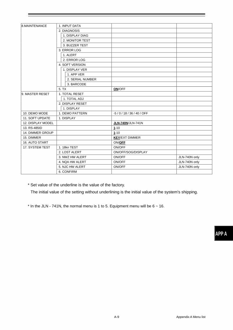
A-9 Appendix A Menu list
APP A
8.MAINTENANCE 1. INPUT DATA 2. DIAGNOSIS 1. DISPLAY DIAG 2. MONITOR TEST 3. BUZZER TEST 3. ERROR LOG 1. ALERT 2. ERROR LOG 4. SOFT VERSION 1. DISPLAY VER 1. APP VER 2. SERIAL NUMBER 3. BARCODE 5. TX ON/OFF
9. MASTER RESET 1. TOTAL RESET 1. TOTAL ADJ 2. DISPLAY RESET 1. DISPLAY 10. DEMO MODE 1. DEMO PATTERN -5 / 0 / 18 / 36 / 40 / OFF 11. SOFT UPDATE 1. DISPLAY 12. DISPLAY MODEL JLN-740N/JLN-741N 13. RS-485ID 1-10 14. DIMMER GROUP 1-10 15. DIMMER KEY/EXT DIMMER 16. AUTO START ON/OFF
17. SYSTEM TEST 1. 18kn TEST ON/OFF 2. LOST ALERT ON/OFF/SOG/DISPLAY 3. NWZ HW ALERT ON/OFF JLN-740N only 4. NQA HW ALERT ON/OFF JLN-740N only 5. NJC HW ALERT ON/OFF JLN-740N only 6. CONFIRM
* Set value of the underline is the value of the factory.
The initial value of the setting without underlining is the initial value of the system's shipping. * In the JLN - 741N, the normal menu is 1 to 5. Equipment menu will be 6 ~ 16.
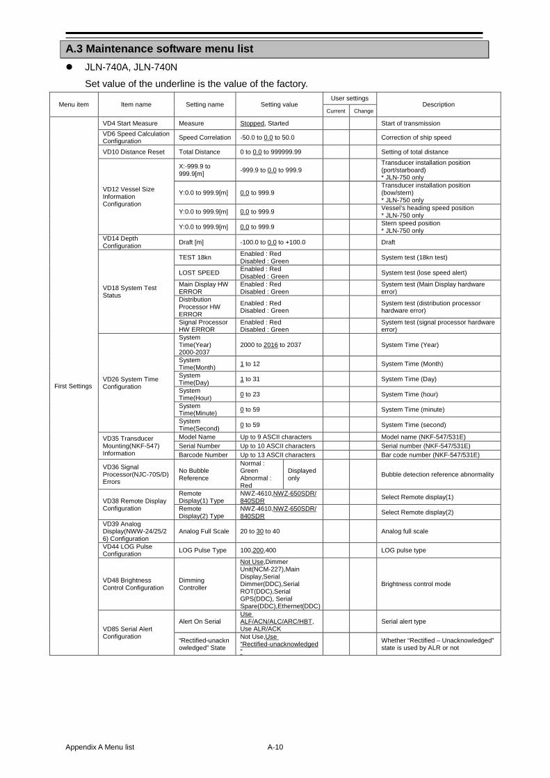
Appendix A Menu list A-10
A.3 Maintenance software menu list JLN-740A, JLN-740N
Set value of the underline is the value of the factory.
Menu item Item name Setting name Setting value User settings
Description Current Change
First Settings
VD4 Start Measure Measure Stopped, Started Start of transmission VD6 Speed Calculation Configuration Speed Correlation -50.0 to 0.0 to 50.0 Correction of ship speed
VD10 Distance Reset Total Distance 0 to 0.0 to 999999.99 Setting of total distance
VD12 Vessel Size Information Configuration
X:-999.9 to 999.9[m] -999.9 to 0.0 to 999.9
Transducer installation position (port/starboard) * JLN-750 only
Y:0.0 to 999.9[m] 0.0 to 999.9 Transducer installation position (bow/stern) * JLN-750 only
Y:0.0 to 999.9[m] 0.0 to 999.9 Vessel’s heading speed position * JLN-750 only
Y:0.0 to 999.9[m] 0.0 to 999.9 Stern speed position * JLN-750 only
VD14 Depth Configuration Draft [m] -100.0 to 0.0 to +100.0 Draft
VD18 System Test Status
TEST 18kn Enabled : Red Disabled : Green
System test (18kn test)
LOST SPEED Enabled : Red Disabled : Green
System test (lose speed alert)
Main Display HW ERROR
Enabled : Red Disabled : Green
System test (Main Display hardware error)
Distribution Processor HW ERROR
Enabled : Red Disabled : Green
System test (distribution processor hardware error)
Signal Processor HW ERROR
Enabled : Red Disabled : Green
System test (signal processor hardware error)
VD26 System Time Configuration
System Time(Year) 2000-2037
2000 to 2016 to 2037 System Time (Year)
System Time(Month) 1 to 12 System Time (Month)
System Time(Day) 1 to 31 System Time (Day)
System Time(Hour) 0 to 23 System Time (hour)
System Time(Minute) 0 to 59 System Time (minute)
System Time(Second) 0 to 59 System Time (second)
VD35 Transducer Mounting(NKF-547) Information
Model Name Up to 9 ASCII characters Model name (NKF-547/531E) Serial Number Up to 10 ASCII characters Serial number (NKF-547/531E) Barcode Number Up to 13 ASCII characters Bar code number (NKF-547/531E)
VD36 Signal Processor(NJC-70S/D) Errors
No Bubble Reference
Normal : Green Abnormal : Red
Displayed only
Bubble detection reference abnormality
VD38 Remote Display Configuration
Remote Display(1) Type
NWZ-4610,NWZ-650SDR/840SDR
Select Remote display(1)
Remote Display(2) Type
NWZ-4610,NWZ-650SDR/840SDR
Select Remote display(2)
VD39 Analog Display(NWW-24/25/26) Configuration
Analog Full Scale 20 to 30 to 40 Analog full scale
VD44 LOG Pulse Configuration LOG Pulse Type 100,200,400 LOG pulse type
VD48 Brightness Control Configuration
Dimming Controller
Not Use,Dimmer Unit(NCM-227),Main Display,Serial Dimmer(DDC),Serial ROT(DDC),Serial GPS(DDC), Serial Spare(DDC),Ethernet(DDC)
Brightness control mode
VD85 Serial Alert Configuration
Alert On Serial Use ALF/ACN/ALC/ARC/HBT,Use ALR/ACK
Serial alert type
“Rectified-unacknowledged” State
Not Use,Use “Rectified-unacknowledged”
Whether “Rectified – Unacknowledged” state is used by ALR or not
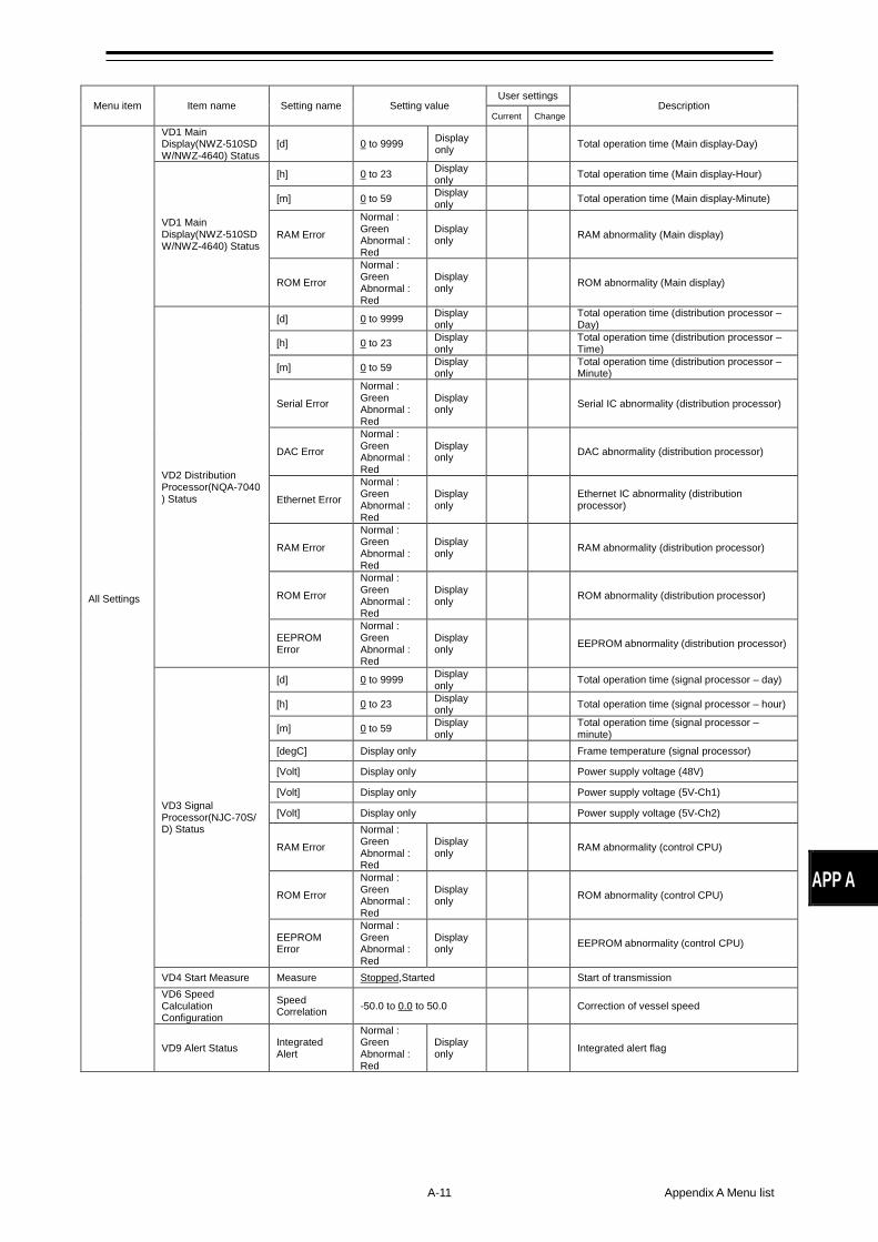
A-11 Appendix A Menu list
APP A
Menu item Item name Setting name Setting value User settings
Description Current Change
All Settings
VD1 Main Display(NWZ-510SDW/NWZ-4640) Status
[d] 0 to 9999 Display only Total operation time (Main display-Day)
VD1 Main Display(NWZ-510SDW/NWZ-4640) Status
[h] 0 to 23 Display only
Total operation time (Main display-Hour)
[m] 0 to 59 Display only
Total operation time (Main display-Minute)
RAM Error
Normal : Green Abnormal : Red
Display only
RAM abnormality (Main display)
ROM Error
Normal : Green Abnormal : Red
Display only
ROM abnormality (Main display)
VD2 Distribution Processor(NQA-7040) Status
[d] 0 to 9999 Display only
Total operation time (distribution processor – Day)
[h] 0 to 23 Display only
Total operation time (distribution processor – Time)
[m] 0 to 59 Display only
Total operation time (distribution processor – Minute)
Serial Error
Normal : Green Abnormal : Red
Display only
Serial IC abnormality (distribution processor)
DAC Error
Normal : Green Abnormal : Red
Display only
DAC abnormality (distribution processor)
Ethernet Error
Normal : Green Abnormal : Red
Display only
Ethernet IC abnormality (distribution processor)
RAM Error
Normal : Green Abnormal : Red
Display only
RAM abnormality (distribution processor)
ROM Error
Normal : Green Abnormal : Red
Display only
ROM abnormality (distribution processor)
EEPROM Error
Normal : Green Abnormal : Red
Display only
EEPROM abnormality (distribution processor)
VD3 Signal Processor(NJC-70S/D) Status
[d] 0 to 9999 Display only
Total operation time (signal processor – day)
[h] 0 to 23 Display only
Total operation time (signal processor – hour)
[m] 0 to 59 Display only
Total operation time (signal processor – minute)
[degC] Display only Frame temperature (signal processor)
[Volt] Display only Power supply voltage (48V)
[Volt] Display only Power supply voltage (5V-Ch1)
[Volt] Display only Power supply voltage (5V-Ch2)
RAM Error
Normal : Green Abnormal : Red
Display only
RAM abnormality (control CPU)
ROM Error
Normal : Green Abnormal : Red
Display only
ROM abnormality (control CPU)
EEPROM Error
Normal : Green Abnormal : Red
Display only
EEPROM abnormality (control CPU)
VD4 Start Measure Measure Stopped,Started Start of transmission VD6 Speed Calculation Configuration
Speed Correlation -50.0 to 0.0 to 50.0 Correction of vessel speed
VD9 Alert Status Integrated Alert
Normal : Green Abnormal : Red
Display only
Integrated alert flag
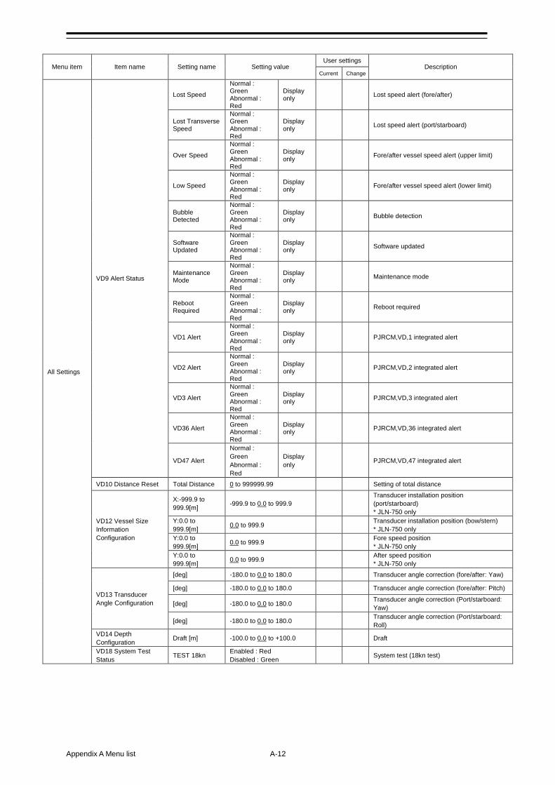
Appendix A Menu list A-12
Menu item Item name Setting name Setting value User settings
Description Current Change
All Settings
VD9 Alert Status
Lost Speed
Normal : Green Abnormal : Red
Display only
Lost speed alert (fore/after)
Lost Transverse Speed
Normal : Green Abnormal : Red
Display only
Lost speed alert (port/starboard)
Over Speed
Normal : Green Abnormal : Red
Display only
Fore/after vessel speed alert (upper limit)
Low Speed
Normal : Green Abnormal : Red
Display only
Fore/after vessel speed alert (lower limit)
Bubble Detected
Normal : Green Abnormal : Red
Display only
Bubble detection
Software Updated
Normal : Green Abnormal : Red
Display only
Software updated
Maintenance Mode
Normal : Green Abnormal : Red
Display only
Maintenance mode
Reboot Required
Normal : Green Abnormal : Red
Display only
Reboot required
VD1 Alert
Normal : Green Abnormal : Red
Display only
PJRCM,VD,1 integrated alert
VD2 Alert
Normal : Green Abnormal : Red
Display only
PJRCM,VD,2 integrated alert
VD3 Alert
Normal : Green Abnormal : Red
Display only
PJRCM,VD,3 integrated alert
VD36 Alert
Normal : Green Abnormal : Red
Display only
PJRCM,VD,36 integrated alert
VD47 Alert
Normal : Green Abnormal : Red
Display only
PJRCM,VD,47 integrated alert
VD10 Distance Reset Total Distance 0 to 999999.99 Setting of total distance
VD12 Vessel Size Information Configuration
X:-999.9 to 999.9[m] -999.9 to 0.0 to 999.9
Transducer installation position (port/starboard) * JLN-750 only
Y:0.0 to 999.9[m] 0.0 to 999.9 Transducer installation position (bow/stern)
* JLN-750 only Y:0.0 to 999.9[m] 0.0 to 999.9 Fore speed position
* JLN-750 only Y:0.0 to 999.9[m] 0.0 to 999.9 After speed position
* JLN-750 only
VD13 Transducer Angle Configuration
[deg] -180.0 to 0.0 to 180.0 Transducer angle correction (fore/after: Yaw)
[deg] -180.0 to 0.0 to 180.0 Transducer angle correction (fore/after: Pitch)
[deg] -180.0 to 0.0 to 180.0 Transducer angle correction (Port/starboard: Yaw)
[deg] -180.0 to 0.0 to 180.0 Transducer angle correction (Port/starboard: Roll)
VD14 Depth Configuration Draft [m] -100.0 to 0.0 to +100.0 Draft
VD18 System Test Status TEST 18kn Enabled : Red
Disabled : Green System test (18kn test)
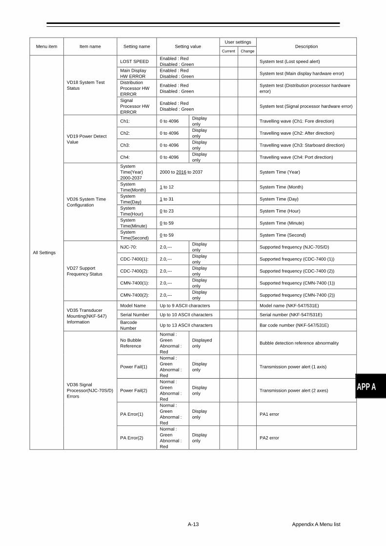
A-13 Appendix A Menu list
APP A
Menu item Item name Setting name Setting value User settings
Description Current Change
All Settings
VD18 System Test Status
LOST SPEED Enabled : Red Disabled : Green
System test (Lost speed alert)
Main Display HW ERROR
Enabled : Red Disabled : Green
System test (Main display hardware error)
Distribution Processor HW ERROR
Enabled : Red Disabled : Green
System test (Distribution processor hardware error)
Signal Processor HW ERROR
Enabled : Red Disabled : Green
System test (Signal processor hardware error)
VD19 Power Detect Value
Ch1: 0 to 4096 Display only
Travelling wave (Ch1: Fore direction)
Ch2: 0 to 4096 Display only
Travelling wave (Ch2: After direction)
Ch3: 0 to 4096 Display only
Travelling wave (Ch3: Starboard direction)
Ch4: 0 to 4096 Display only
Travelling wave (Ch4: Port direction)
VD26 System Time Configuration
System Time(Year) 2000-2037
2000 to 2016 to 2037 System Time (Year)
System Time(Month) 1 to 12 System Time (Month)
System Time(Day) 1 to 31 System Time (Day)
System Time(Hour) 0 to 23 System Time (Hour)
System Time(Minute) 0 to 59 System Time (Minute)
System Time(Second) 0 to 59 System Time (Second)
VD27 Support Frequency Status
NJC-70: 2.0,--- Display only
Supported frequency (NJC-70S/D)
CDC-7400(1): 2.0,--- Display only
Supported frequency (CDC-7400 (1))
CDC-7400(2): 2.0,--- Display only
Supported frequency (CDC-7400 (2))
CMN-7400(1): 2.0,--- Display only
Supported frequency (CMN-7400 (1))
CMN-7400(2): 2.0,--- Display only
Supported frequency (CMN-7400 (2))
VD35 Transducer Mounting(NKF-547) Information
Model Name Up to 9 ASCII characters Model name (NKF-547/531E)
Serial Number Up to 10 ASCII characters Serial number (NKF-547/531E) Barcode Number Up to 13 ASCII characters Bar code number (NKF-547/531E)
VD36 Signal Processor(NJC-70S/D) Errors
No Bubble Reference
Normal : Green Abnormal : Red
Displayed only
Bubble detection reference abnormality
Power Fail(1)
Normal : Green Abnormal : Red
Display only
Transmission power alert (1 axis)
Power Fail(2)
Normal : Green Abnormal : Red
Display only
Transmission power alert (2 axes)
PA Error(1)
Normal : Green Abnormal : Red
Display only
PA1 error
PA Error(2)
Normal : Green Abnormal : Red
Display only
PA2 error
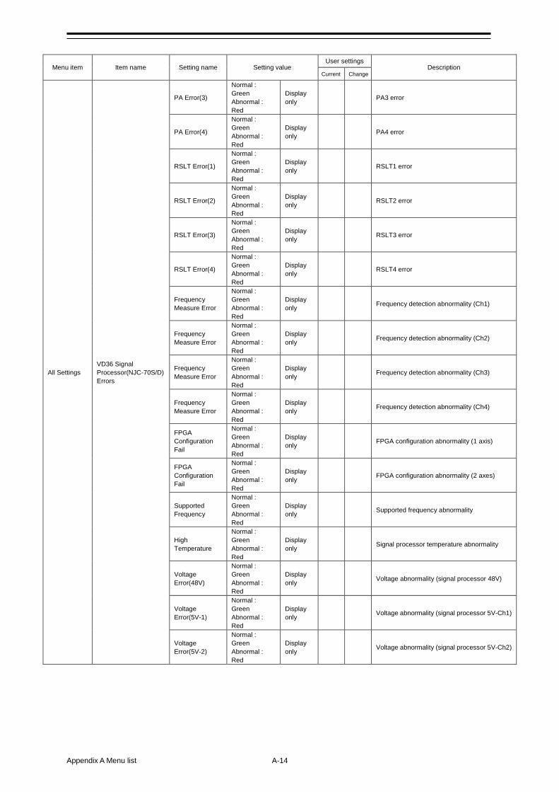
Appendix A Menu list A-14
Menu item Item name Setting name Setting value User settings
Description Current Change
All Settings VD36 Signal Processor(NJC-70S/D) Errors
PA Error(3)
Normal : Green Abnormal : Red
Display only
PA3 error
PA Error(4)
Normal : Green Abnormal : Red
Display only
PA4 error
RSLT Error(1)
Normal : Green Abnormal : Red
Display only
RSLT1 error
RSLT Error(2)
Normal : Green Abnormal : Red
Display only
RSLT2 error
RSLT Error(3)
Normal : Green Abnormal : Red
Display only
RSLT3 error
RSLT Error(4)
Normal : Green Abnormal : Red
Display only
RSLT4 error
Frequency Measure Error
Normal : Green Abnormal : Red
Display only
Frequency detection abnormality (Ch1)
Frequency Measure Error
Normal : Green Abnormal : Red
Display only
Frequency detection abnormality (Ch2)
Frequency Measure Error
Normal : Green Abnormal : Red
Display only
Frequency detection abnormality (Ch3)
Frequency Measure Error
Normal : Green Abnormal : Red
Display only
Frequency detection abnormality (Ch4)
FPGA Configuration Fail
Normal : Green Abnormal : Red
Display only
FPGA configuration abnormality (1 axis)
FPGA Configuration Fail
Normal : Green Abnormal : Red
Display only
FPGA configuration abnormality (2 axes)
Supported Frequency
Normal : Green Abnormal : Red
Display only
Supported frequency abnormality
High Temperature
Normal : Green Abnormal : Red
Display only
Signal processor temperature abnormality
Voltage Error(48V)
Normal : Green Abnormal : Red
Display only
Voltage abnormality (signal processor 48V)
Voltage Error(5V-1)
Normal : Green Abnormal : Red
Display only
Voltage abnormality (signal processor 5V-Ch1)
Voltage Error(5V-2)
Normal : Green Abnormal : Red
Display only
Voltage abnormality (signal processor 5V-Ch2)
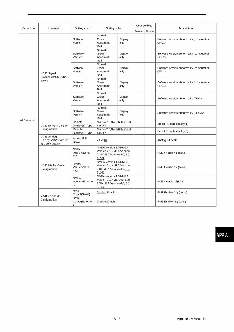
A-15 Appendix A Menu list
APP A
Menu item Item name Setting name Setting value User settings
Description Current Change
All Settings
VD36 Signal Processor(NJC-70S/D) Errors
Software Version
Normal : Green Abnormal : Red
Display only
Software version abnormality (computation CPU1)
Software Version
Normal : Green Abnormal : Red
Display only
Software version abnormality (computation CPU2)
Software Version
Normal : Green Abnormal : Red
Display only
Software version abnormality (computation CPU3)
Software Version
Normal : Green Abnormal : Red
Display only
Software version abnormality (computation CPU4)
Software Version
Normal : Green Abnormal : Red
Display only
Software version abnormality (FPGA1)
Software Version
Normal : Green Abnormal : Red
Display only
Software version abnormality (FPGA2)
VD38 Remote Display Configuration
Remote Display(1) Type
NWZ-4610,NWZ-650SDR/840SDR
Select Remote display(1)
Remote Display(2) Type
NWZ-4610,NWZ-650SDR/840SDR
Select Remote display(2)
VD39 Analog Display(NWW-24/25/26) Configuration
Analog Full Scale 20 to 40 Analog full scale
VD40 NMEA Version Configuration
NMEA Version(Serial Tx1)
NMEA Version 1.5,NMEA Version 2.1,NMEA Version 2.3,NMEA Version 4.0,IEC 61162
NMEA version 1 (serial)
NMEA Version(Serial Tx2)
NMEA Version 1.5,NMEA Version 2.1,NMEA Version 2.3,NMEA Version 4.0,IEC 61162
NMEA version 2 (serial)
NMEA Version(Ethernet)
NMEA Version 1.5,NMEA Version 2.1,NMEA Version 2.3,NMEA Version 4.0,IEC 61162
NMEA version 3(LAN)
VD41 JRC-RMS Configuration
RMS Output(Serial) Disable,Enable RMS Enable flag (serial)
RMS Output(Ethernet)
Disable,Enable RMS Enable flag (LAN)
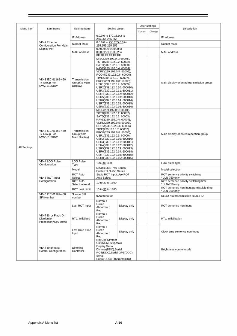
Appendix A Menu list A-16
Menu item Item name Setting name Setting value User settings
Description Current Change
All Settings
VD42 Ethernet Configuration For Main Display Port
IP Address 0.0.0.0 to 172.16.0.2 to 255.255.255.255
IP address
Subnet Mask 0.0.0.0 to 255.255.0.0 to 255.255.255.255
Subnet mask
MAC Address 00:00:00:00:00:00 to 00:00:27:00:00:02 to FF:FF:FF:FF:FF:FF
MAC address
VD43 IEC 61162-450 Tx Group For NWZ-510SDW
Transmission Group(to Main Display)
MISC(239.192.0.1: 60001), TGTD(239.192.0.2: 60002), SATD(239.192.0.3: 60003), NAVD(239.192.0.4: 60004), VDRD(239.192.0.5: 60005), RCOM(239.192.0.6: 60006), TIME(239.192.0.7: 60007), PROP(239.192.0.8: 60008), USR1(239.192.0.9: 60009), USR2(239.192.0.10: 600010), USR3(239.192.0.11: 600011), USR4(239.192.0.12: 600012), USR5(239.192.0.13: 600013), USR6(239.192.0.14: 600014), USR7(239.192.0.15: 600015), USR8(239.192.0.16: 600016)
Main display oriented transmission group
VD43 IEC 61162-450 Tx Group For NWZ-510SDW
Transmission Group(from Main Display)
MISC(239.192.0.1: 60001), TGTD(239.192.0.2: 60002), SATD(239.192.0.3: 60003), NAVD(239.192.0.4: 60004), VDRD(239.192.0.5: 60005), RCOM(239.192.0.6: 60006), TIME(239.192.0.7: 60007), PROP(239.192.0.8: 60008), USR1(239.192.0.9: 60009), USR2(239.192.0.10: 600010), USR3(239.192.0.11: 600011), USR4(239.192.0.12: 600012), USR5(239.192.0.13: 600013), USR6(239.192.0.14: 600014), USR7(239.192.0.15: 600015), USR8(239.192.0.16: 600016)
Main display oriented reception group
VD44 LOG Pulse Configuration
LOG Pulse Type 100,200,400 LOG pulse type
VD45 ROT Input Configuration
Model Disable:JLN-740 Series Enable:JLN-750 Series
Model selection
ROT Auto Select
Static ROT Input,Use ROT Auto Select
ROT sentence priority switching * JLN-750 only
ROT Auto Select Interval 10 to 30 to 1800 ROT sentence priority switching time
* JLN-750 only
ROT Lost Limit 10 to 30 to 1800 ROT sentence non-input permissible time * JLN-750 only
VD46 IEC 61162-450 SFI Number
Source SFI number 0000 to 9999 61162-450 transmission source ID
VD47 Error Flags On Distribution Processor(NQA-7040)
Lost ROT Input
Normal : Green Abnormal : Red
Display only ROT sentence non-input
RTC Initialized
Normal : Green Abnormal : Red
Display only RTC initialization
Lost Date-Time Input
Normal : Green Abnormal : Red
Display only Clock time sentence non-input
VD48 Brightness Control Configuration
Dimming Controller
Not Use,Dimmer Unit(NCM-227),Main Display,Serial Dimmer(DDC),Serial ROT(DDC),Serial GPS(DDC), Serial Spare(DDC),Ethernet(DDC)
Brightness control mode
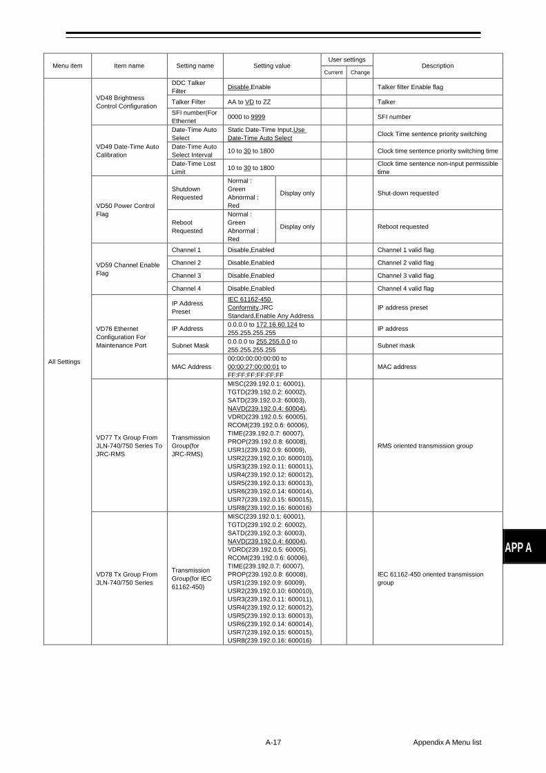
A-17 Appendix A Menu list
APP A
Menu item Item name Setting name Setting value User settings
Description Current Change
All Settings
VD48 Brightness Control Configuration
DDC Talker Filter Disable,Enable Talker filter Enable flag
Talker Filter AA to VD to ZZ Talker SFI number(For Ethernet 0000 to 9999 SFI number
VD49 Date-Time Auto Calibration
Date-Time Auto Select
Static Date-Time Input,Use Date-Time Auto Select
Clock Time sentence priority switching
Date-Time Auto Select Interval 10 to 30 to 1800 Clock time sentence priority switching time
Date-Time Lost Limit 10 to 30 to 1800 Clock time sentence non-input permissible
time
VD50 Power Control Flag
Shutdown Requested
Normal : Green Abnormal : Red
Display only Shut-down requested
Reboot Requested
Normal : Green Abnormal : Red
Display only Reboot requested
VD59 Channel Enable Flag
Channel 1 Disable,Enabled Channel 1 valid flag
Channel 2 Disable,Enabled Channel 2 valid flag
Channel 3 Disable,Enabled Channel 3 valid flag
Channel 4 Disable,Enabled Channel 4 valid flag
VD76 Ethernet Configuration For Maintenance Port
IP Address Preset
IEC 61162-450 Conformity,JRC Standard,Enable Any Address
IP address preset
IP Address 0.0.0.0 to 172.16.60.124 to 255.255.255.255
IP address
Subnet Mask 0.0.0.0 to 255.255.0.0 to 255.255.255.255
Subnet mask
MAC Address 00:00:00:00:00:00 to 00:00:27:00:00:01 to FF:FF:FF:FF:FF:FF
MAC address
VD77 Tx Group From JLN-740/750 Series To JRC-RMS
Transmission Group(for JRC-RMS)
MISC(239.192.0.1: 60001), TGTD(239.192.0.2: 60002), SATD(239.192.0.3: 60003), NAVD(239.192.0.4: 60004), VDRD(239.192.0.5: 60005), RCOM(239.192.0.6: 60006), TIME(239.192.0.7: 60007), PROP(239.192.0.8: 60008), USR1(239.192.0.9: 60009), USR2(239.192.0.10: 600010), USR3(239.192.0.11: 600011), USR4(239.192.0.12: 600012), USR5(239.192.0.13: 600013), USR6(239.192.0.14: 600014), USR7(239.192.0.15: 600015), USR8(239.192.0.16: 600016)
RMS oriented transmission group
VD78 Tx Group From JLN-740/750 Series
Transmission Group(for IEC 61162-450)
MISC(239.192.0.1: 60001), TGTD(239.192.0.2: 60002), SATD(239.192.0.3: 60003), NAVD(239.192.0.4: 60004), VDRD(239.192.0.5: 60005), RCOM(239.192.0.6: 60006), TIME(239.192.0.7: 60007), PROP(239.192.0.8: 60008), USR1(239.192.0.9: 60009), USR2(239.192.0.10: 600010), USR3(239.192.0.11: 600011), USR4(239.192.0.12: 600012), USR5(239.192.0.13: 600013), USR6(239.192.0.14: 600014), USR7(239.192.0.15: 600015), USR8(239.192.0.16: 600016)
IEC 61162-450 oriented transmission group
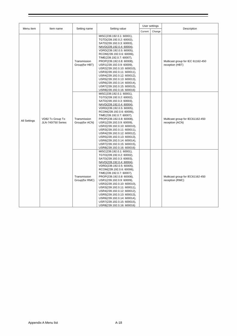
Appendix A Menu list A-18
Menu item Item name Setting name Setting value User settings
Description Current Change
All Settings VD82 Tx Group To JLN-740/750 Series
Transmission Group(for HBT)
MISC(239.192.0.1: 60001), TGTD(239.192.0.2: 60002), SATD(239.192.0.3: 60003), NAVD(239.192.0.4: 60004), VDRD(239.192.0.5: 60005), RCOM(239.192.0.6: 60006), TIME(239.192.0.7: 60007), PROP(239.192.0.8: 60008), USR1(239.192.0.9: 60009), USR2(239.192.0.10: 600010), USR3(239.192.0.11: 600011), USR4(239.192.0.12: 600012), USR5(239.192.0.13: 600013), USR6(239.192.0.14: 600014), USR7(239.192.0.15: 600015), USR8(239.192.0.16: 600016)
Multicast group for IEC 61162-450 reception (HBT)
Transmission Group(for ACN)
MISC(239.192.0.1: 60001), TGTD(239.192.0.2: 60002), SATD(239.192.0.3: 60003), NAVD(239.192.0.4: 60004), VDRD(239.192.0.5: 60005), RCOM(239.192.0.6: 60006), TIME(239.192.0.7: 60007), PROP(239.192.0.8: 60008), USR1(239.192.0.9: 60009), USR2(239.192.0.10: 600010), USR3(239.192.0.11: 600011), USR4(239.192.0.12: 600012), USR5(239.192.0.13: 600013), USR6(239.192.0.14: 600014), USR7(239.192.0.15: 600015), USR8(239.192.0.16: 600016)
Multicast group for IEC61162-450 reception (ACN)
Transmission Group(for RMC)
MISC(239.192.0.1: 60001), TGTD(239.192.0.2: 60002), SATD(239.192.0.3: 60003), NAVD(239.192.0.4: 60004), VDRD(239.192.0.5: 60005), RCOM(239.192.0.6: 60006), TIME(239.192.0.7: 60007), PROP(239.192.0.8: 60008), USR1(239.192.0.9: 60009), USR2(239.192.0.10: 600010), USR3(239.192.0.11: 600011), USR4(239.192.0.12: 600012), USR5(239.192.0.13: 600013), USR6(239.192.0.14: 600014), USR7(239.192.0.15: 600015), USR8(239.192.0.16: 600016)
Multicast group for IEC61162-450 reception (RMC)
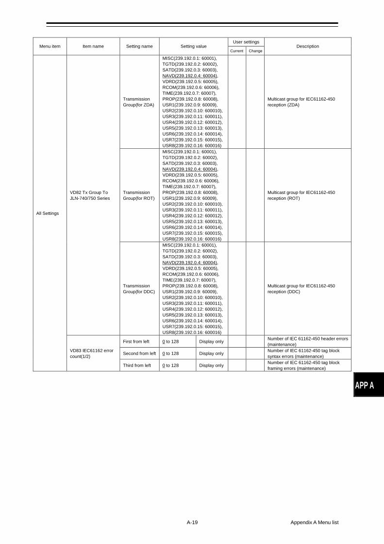
A-19 Appendix A Menu list
APP A
Menu item Item name Setting name Setting value User settings
Description Current Change
All Settings
VD82 Tx Group To JLN-740/750 Series
Transmission Group(for ZDA)
MISC(239.192.0.1: 60001), TGTD(239.192.0.2: 60002), SATD(239.192.0.3: 60003), NAVD(239.192.0.4: 60004), VDRD(239.192.0.5: 60005), RCOM(239.192.0.6: 60006), TIME(239.192.0.7: 60007), PROP(239.192.0.8: 60008), USR1(239.192.0.9: 60009), USR2(239.192.0.10: 600010), USR3(239.192.0.11: 600011), USR4(239.192.0.12: 600012), USR5(239.192.0.13: 600013), USR6(239.192.0.14: 600014), USR7(239.192.0.15: 600015), USR8(239.192.0.16: 600016)
Multicast group for IEC61162-450 reception (ZDA)
Transmission Group(for ROT)
MISC(239.192.0.1: 60001), TGTD(239.192.0.2: 60002), SATD(239.192.0.3: 60003), NAVD(239.192.0.4: 60004), VDRD(239.192.0.5: 60005), RCOM(239.192.0.6: 60006), TIME(239.192.0.7: 60007), PROP(239.192.0.8: 60008), USR1(239.192.0.9: 60009), USR2(239.192.0.10: 600010), USR3(239.192.0.11: 600011), USR4(239.192.0.12: 600012), USR5(239.192.0.13: 600013), USR6(239.192.0.14: 600014), USR7(239.192.0.15: 600015), USR8(239.192.0.16: 600016)
Multicast group for IEC61162-450 reception (ROT)
Transmission Group(for DDC)
MISC(239.192.0.1: 60001), TGTD(239.192.0.2: 60002), SATD(239.192.0.3: 60003), NAVD(239.192.0.4: 60004), VDRD(239.192.0.5: 60005), RCOM(239.192.0.6: 60006), TIME(239.192.0.7: 60007), PROP(239.192.0.8: 60008), USR1(239.192.0.9: 60009), USR2(239.192.0.10: 600010), USR3(239.192.0.11: 600011), USR4(239.192.0.12: 600012), USR5(239.192.0.13: 600013), USR6(239.192.0.14: 600014), USR7(239.192.0.15: 600015), USR8(239.192.0.16: 600016)
Multicast group for IEC61162-450 reception (DDC)
VD83 IEC61162 error count(1/2)
First from left 0 to 128 Display only Number of IEC 61162-450 header errors (maintenance)
Second from left 0 to 128 Display only Number of IEC 61162-450 tag block syntax errors (maintenance)
Third from left 0 to 128 Display only Number of IEC 61162-450 tag block framing errors (maintenance)
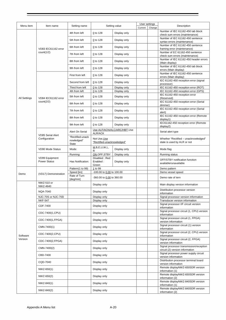
Appendix A Menu list A-20
Menu item Item name Setting name Setting value
User settings Description
Current Change
All Settings
VD83 IEC61162 error count(1/2)
4th from left 0 to 128 Display only Number of IEC 61162-450 tab block check sum errors (maintenance)
5th from left 0 to 128 Display only Number of IEC 61162-450 sentence syntax errors (maintenance)
6th from left 0 to 128 Display only Number of IEC 61162-450 sentence framing error (maintenance)
7th from left 0 to 128 Display only Number of EC 61162-450 sentence check sum errors (maintenance)
8th from left 0 to 128 Display only Number of IEC 61162-450 header errors (Main display)
9th from left 0 to 128 Display only Number of IEC 61162-450 tab block errors (Main display)
VD84 IEC61162 error count(2/2)
First from left 0 to 128 Display only Number of IEC 61162-450 sentence errors (Main display)
Second from left 0 to 128 Display only IEC 61162-450 reception error (signal processor)
Third from left 0 to 128 Display only IEC 61162-450 reception error (ROT) 4th from left 0 to 128 Display only IEC 61162-450 reception error (GPS)
5th from left 0 to 128 Display only IEC 61162-450 reception error (Reserved)
6th from left 0 to 128 Display only IEC 61162-450 reception error (Serial dimmer)
7th from left 0 to 128 Display only IEC 61162-450 reception error (Serial alert)
8th from left 0 to 128 Display only IEC 61162-450 reception error (Remote display1)
9th from left 0 to 128 Display only IEC61162-450 reception error (Remote display2)
VD85 Serial Alert Configuration
Alert On Serial Use ALF/ACN/ALC/ARC/HBT,Use ALR/ACK
Serial alert type
“Rectified-unacknowledged” State
Not Use,Use “Rectified-unacknowledged”
Whether “Rectified – unacknowledged” state is used by ALR or not
VD90 Mode Status Mode: M,B,E,U,W,L,R Display only Mode flag
VD99 Equipment Power Status
Running: ON,OFF,STBY Display only Running status
Has Notification: Disabled : Red Enabled : Green
Display only OFF/STBY notification function available/unavailable
Demo (VD17) Demonstration
Pattern(1 to 99) 1 to 99 Demo pattern Speed [kn] -100.00 to 0.00 to 100.00 Demo vessel speed Rate of Turn [deg/min] -360.00 to 0.00 to 360.00 Demo rate of tern
Software Version
NWZ-510 or NWZ-4640 Display only Main display version information
NQA-7040 Display only Distribution processor version information
NJC-70S or NJC-70D Display only Signal processor version information NKF-547 Display only Transducer version information
CDF-7400 Display only Signal processor I/F circuit version information
CDC-7400(1,CPU) Display only Signal processor circuit (1, CPU) version information
CDC-7400(1,FPGA) Display only Signal processor circuit (1, FPGA) version information
CMN-7400(1) Display only Signal processor circuit (1) version information
CDC-7400(2,CPU) Display only Signal processor circuit (2, CPU) version information
CDC-7400(2,FPGA) Display only Signal processor circuit (2, FPGA) version information
CMN-7400(2) Display only Signal processor transmission/reception circuit (2) version information
CBD-7400 Display only Signal processor power supply circuit version information
CQD-7040 Display only Distribution processor terminal board version information
NWZ-650(1) Display only Remote displayNWZ-650SDR version information (1)
NWZ-650(2) Display only Remote displayNWZ-650SDR version information (2)
NWZ-840(1) Display only Remote displayNWZ-840SDR version information (1)
NWZ-840(2) Display only Remote displayNWZ-840SDR version information (2)
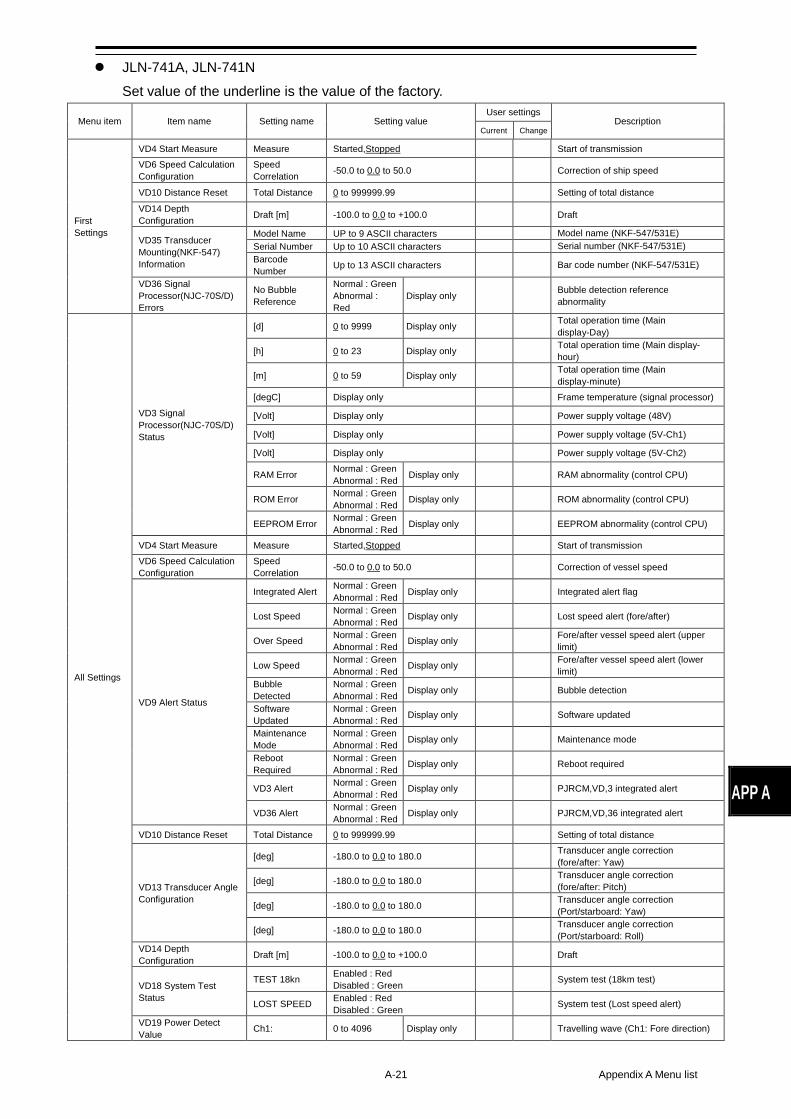
A-21 Appendix A Menu list
APP A
JLN-741A, JLN-741N Set value of the underline is the value of the factory.
Menu item Item name Setting name Setting value User settings
Description Current Change
First Settings
VD4 Start Measure Measure Started,Stopped Start of transmission VD6 Speed Calculation Configuration
Speed Correlation -50.0 to 0.0 to 50.0 Correction of ship speed
VD10 Distance Reset Total Distance 0 to 999999.99 Setting of total distance
VD14 Depth Configuration Draft [m] -100.0 to 0.0 to +100.0 Draft
VD35 Transducer Mounting(NKF-547) Information
Model Name UP to 9 ASCII characters Model name (NKF-547/531E) Serial Number Up to 10 ASCII characters Serial number (NKF-547/531E) Barcode Number Up to 13 ASCII characters Bar code number (NKF-547/531E)
VD36 Signal Processor(NJC-70S/D) Errors
No Bubble Reference
Normal : Green Abnormal : Red
Display only Bubble detection reference abnormality
All Settings
VD3 Signal Processor(NJC-70S/D) Status
[d] 0 to 9999 Display only Total operation time (Main display-Day)
[h] 0 to 23 Display only Total operation time (Main display- hour)
[m] 0 to 59 Display only Total operation time (Main display-minute)
[degC] Display only Frame temperature (signal processor)
[Volt] Display only Power supply voltage (48V)
[Volt] Display only Power supply voltage (5V-Ch1)
[Volt] Display only Power supply voltage (5V-Ch2)
RAM Error Normal : Green Abnormal : Red Display only RAM abnormality (control CPU)
ROM Error Normal : Green Abnormal : Red Display only ROM abnormality (control CPU)
EEPROM Error Normal : Green Abnormal : Red Display only EEPROM abnormality (control CPU)
VD4 Start Measure Measure Started,Stopped Start of transmission VD6 Speed Calculation Configuration
Speed Correlation -50.0 to 0.0 to 50.0 Correction of vessel speed
VD9 Alert Status
Integrated Alert Normal : Green Abnormal : Red Display only Integrated alert flag
Lost Speed Normal : Green Abnormal : Red Display only Lost speed alert (fore/after)
Over Speed Normal : Green Abnormal : Red Display only Fore/after vessel speed alert (upper
limit)
Low Speed Normal : Green Abnormal : Red Display only Fore/after vessel speed alert (lower
limit) Bubble Detected
Normal : Green Abnormal : Red Display only Bubble detection
Software Updated
Normal : Green Abnormal : Red Display only Software updated
Maintenance Mode
Normal : Green Abnormal : Red Display only Maintenance mode
Reboot Required
Normal : Green Abnormal : Red Display only Reboot required
VD3 Alert Normal : Green Abnormal : Red Display only PJRCM,VD,3 integrated alert
VD36 Alert Normal : Green Abnormal : Red Display only PJRCM,VD,36 integrated alert
VD10 Distance Reset Total Distance 0 to 999999.99 Setting of total distance
VD13 Transducer Angle Configuration
[deg] -180.0 to 0.0 to 180.0 Transducer angle correction (fore/after: Yaw)
[deg] -180.0 to 0.0 to 180.0 Transducer angle correction (fore/after: Pitch)
[deg] -180.0 to 0.0 to 180.0 Transducer angle correction (Port/starboard: Yaw)
[deg] -180.0 to 0.0 to 180.0 Transducer angle correction (Port/starboard: Roll)
VD14 Depth Configuration Draft [m] -100.0 to 0.0 to +100.0 Draft
VD18 System Test Status
TEST 18kn Enabled : Red Disabled : Green
System test (18km test)
LOST SPEED Enabled : Red Disabled : Green
System test (Lost speed alert)
VD19 Power Detect Value Ch1: 0 to 4096 Display only Travelling wave (Ch1: Fore direction)

Appendix A Menu list A-22
Menu item Item name Setting name Setting value User settings
Description Current Change
All Settings
VD19 Power Detect Value
Ch2: 0 to 4096 Display only Travelling wave (Ch2: After direction)
Ch3: 0 to 4096 Display only Travelling wave (Ch3: Starboard direction)
Ch4: 0 to 4096 Display only Travelling wave (Ch4: Port direction)
VD27 Support Frequency Configuration
NJC-70: 2.0,--- Display only Supported frequency (NJC-70S/D)
CDC-7400(1): 2.0,--- Display only Supported frequency (CDC-7400 (1))
CDC-7400(2): 2.0,--- Display only Supported frequency (CDC-7400 (2))
CMN-7400(1): 2.0,--- Display only Supported frequency (CMN-7400 (1))
CMN-7400(2): 2.0,--- Display only Supported frequency (CMN-7400 (2))
VD35 Transducer Mounting(NKF-547) Information
Model Name Up to 9 ASCII characters Model name (NKF-547/531E)
Serial Number Up to 10 ASCII characters Serial number (NKF-547/531E) Barcode Number Up to 13 ASCII characters Bar code number (NKF-547/531E)
VD36 Signal Processor(NJC-70S/D) Errors
No Bubble Reference
Normal : Green Abnormal : Red Display only Bubble detection reference abnormality
Power Fail(1) Normal : Green Abnormal : Red Display only Transmission power alert (1 axis)
Power Fail(2) Normal : Green Abnormal : Red Display only Transmission power alert (2 axes)
PA Error(1) Normal : Green Abnormal : Red Display only PA1 error
PA Error(2) Normal : Green Abnormal : Red Display only PA2 error
PA Error(3) Normal : Green Abnormal : Red Display only PA3 error
PA Error(4) Normal : Green Abnormal : Red Display only PA4 error
RSLT Error(1) Normal : Green Abnormal : Red Display only RSLT1 error
RSLT Error(2) Normal : Green Abnormal : Red Display only RSLT2 error
RSLT Error(3) Normal : Green Abnormal : Red Display only RSLT3 error
RSLT Error(4) Normal : Green Abnormal : Red Display only RSLT4 error
Frequency Measure Error
Normal : Green Abnormal : Red Display only Frequency detection abnormality (Ch1)
Frequency Measure Error
Normal : Green Abnormal : Red Display only Frequency detection abnormality (Ch2)
Frequency Measure Error
Normal : Green Abnormal : Red Display only Frequency detection abnormality (Ch3)
Frequency Measure Error
Normal : Green Abnormal : Red Display only Frequency detection abnormality (Ch4)
FPGA Configuration Fail
Normal : Green Abnormal : Red Display only FPGA configuration abnormality (1 axis)
FPGA Configuration Fail
Normal : Green Abnormal : Red Display only FPGA configuration abnormality (2 axes)
Supported Frequency
Normal : Green Abnormal : Red Display only Supported frequency abnormality
High Temperature
Normal : Green Abnormal : Red Display only Signal processor temperature
abnormality Voltage Error(48V)
Normal : Green Abnormal : Red Display only Voltage abnormality (signal processor
48V) Voltage Error(5V-1)
Normal : Green Abnormal : Red Display only Voltage abnormality (signal processor
5V-Ch1) Voltage Error(5V-2)
Normal : Green Abnormal : Red Display only Voltage abnormality (signal processor
5V-Ch2) Software Version
Normal : Green Abnormal : Red Display only Software version abnormality
(computation CPU1) Software Version
Normal : Green Abnormal : Red Display only Software version abnormality
(computation CPU2) Software Version
Normal : Green Abnormal : Red Display only Software version abnormality
(computation CPU3) Software Version
Normal : Green Abnormal : Red Display only Software version abnormality
(computation CPU4) Software Version
Normal : Green Abnormal : Red Display only Software version abnormality
(computation (FPGA1) Software Version
Normal : Green Abnormal : Red Display only Software version abnormality
(computation (FPGA2)
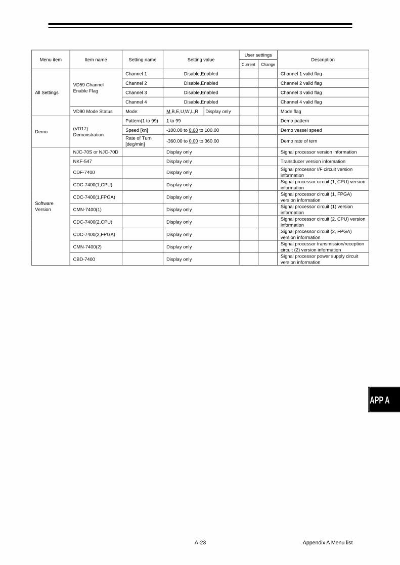
A-23 Appendix A Menu list
APP A
Menu item Item name Setting name Setting value User settings
Description Current Change
All Settings VD59 Channel Enable Flag
Channel 1 Disable,Enabled Channel 1 valid flag
Channel 2 Disable,Enabled Channel 2 valid flag
Channel 3 Disable,Enabled Channel 3 valid flag
Channel 4 Disable,Enabled Channel 4 valid flag
VD90 Mode Status Mode: M,B,E,U,W,L,R Display only Mode flag
Demo (VD17) Demonstration
Pattern(1 to 99) 1 to 99 Demo pattern
Speed [kn] -100.00 to 0.00 to 100.00 Demo vessel speed Rate of Turn [deg/min] -360.00 to 0.00 to 360.00 Demo rate of tern
Software Version
NJC-70S or NJC-70D Display only Signal processor version information
NKF-547 Display only Transducer version information
CDF-7400 Display only Signal processor I/F circuit version information
CDC-7400(1,CPU) Display only Signal processor circuit (1, CPU) version information
CDC-7400(1,FPGA) Display only Signal processor circuit (1, FPGA) version information
CMN-7400(1) Display only Signal processor circuit (1) version information
CDC-7400(2,CPU) Display only Signal processor circuit (2, CPU) version information
CDC-7400(2,FPGA) Display only Signal processor circuit (2, FPGA) version information
CMN-7400(2) Display only Signal processor transmission/reception circuit (2) version information
CBD-7400 Display only Signal processor power supply circuit version information

Appendix A Menu list A-24
(This page intentionally left blank)
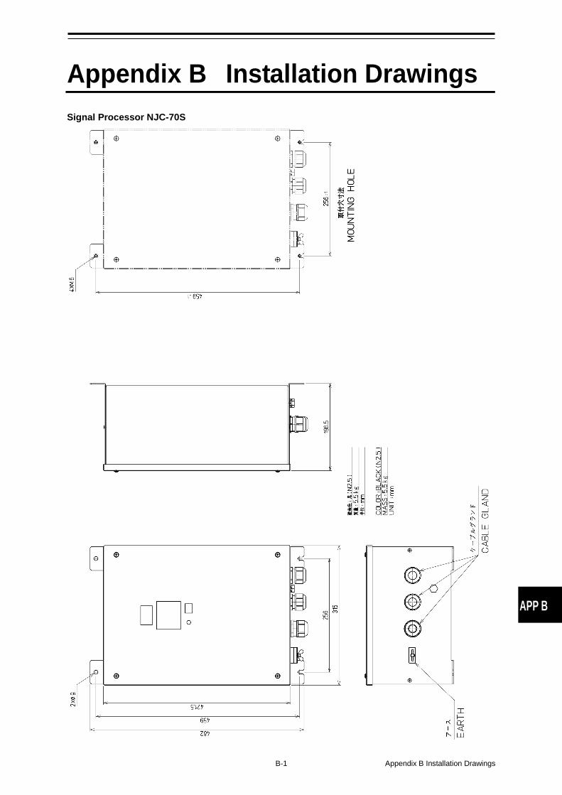
B-1 Appendix B Installation Drawings
APP B
Appendix B Installation Drawings Signal Processor NJC-70S
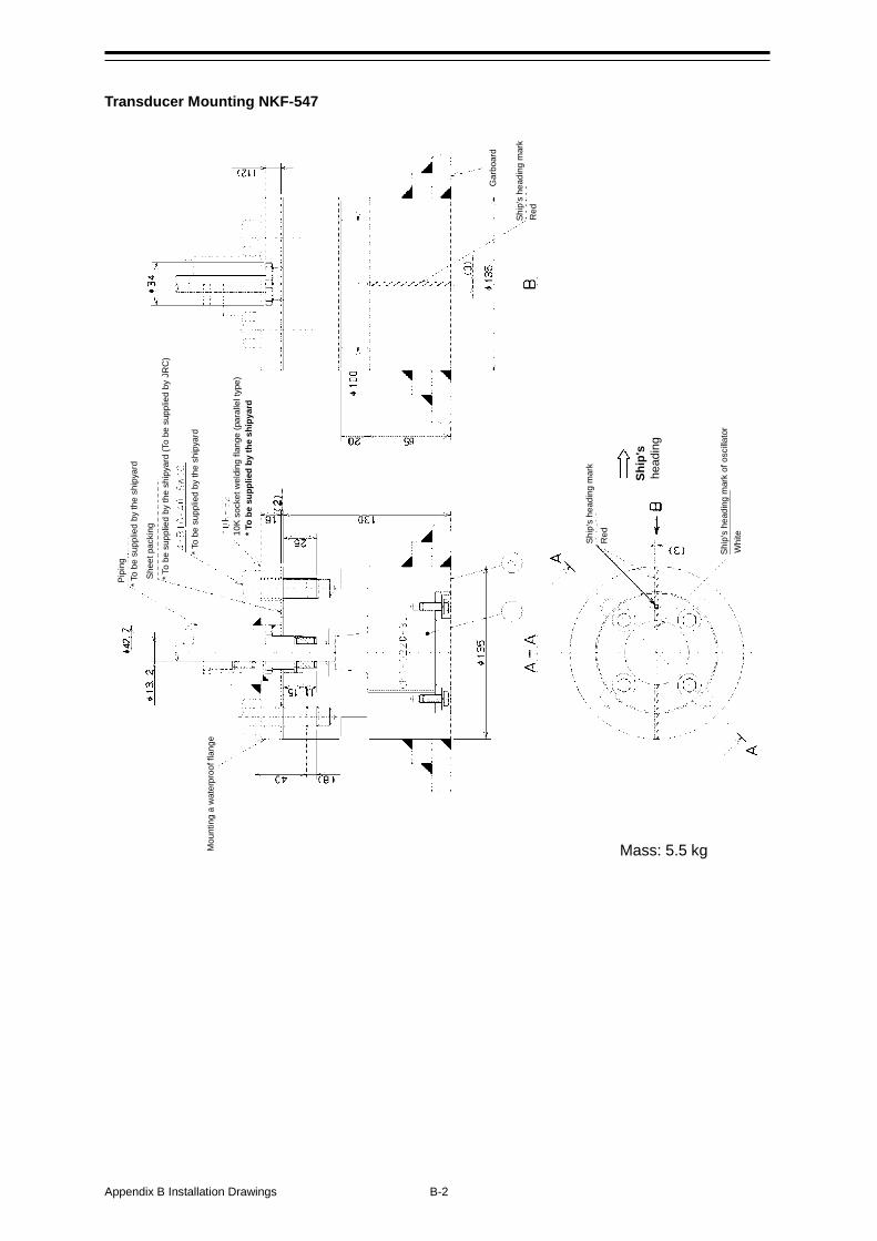
Appendix B Installation Drawings B-2
Pipi
ng
* To
be s
uppl
ied
by th
e sh
ipya
rd
Shee
t pac
king
* T
o be
sup
plie
d by
the
ship
yard
(To
be s
uppl
ied
by J
RC
)
* To
be s
uppl
ied
by th
e sh
ipya
rd
10K
sock
et w
eldi
ng fl
ange
(par
alle
l typ
e)
* To
be s
uppl
ied
by th
e sh
ipya
rd
Mou
ntin
g a
wat
erpr
oof f
lang
e
Gar
boar
d
Red
Ship
's h
eadi
ng m
ark
of o
scilla
tor
Ship
's h
eadi
ng m
ark
Red
Whi
te
Ship
's
head
ing
Mass: 5.5 kg
Ship
's h
eadi
ng m
ark
Transducer Mounting NKF-547
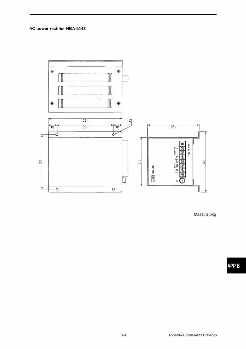
B-3 Appendix B Installation Drawings
APP B
AC power rectifier NBA-5143
Mass: 3.5kg
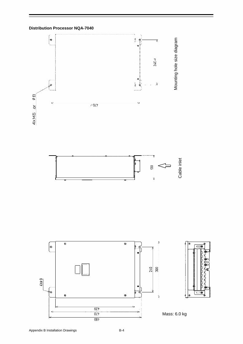
Appendix B Installation Drawings B-4
Distribution Processor NQA-7040
or
Mou
ntin
g ho
le s
ize
diag
ram
C
able
inle
t
Mass: 6.0 kg
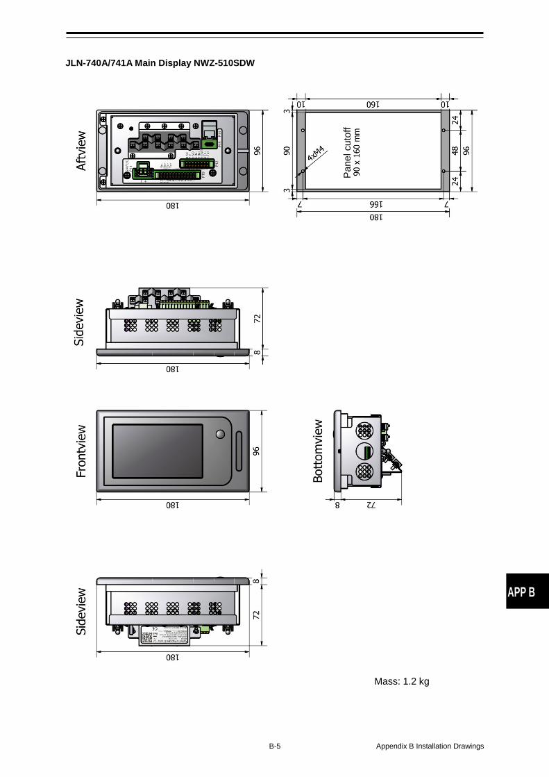
B-5 Appendix B Installation Drawings
APP B
JLN-740A/741A Main Display NWZ-510SDW
Pane
l cut
off
Mass: 1.2 kg
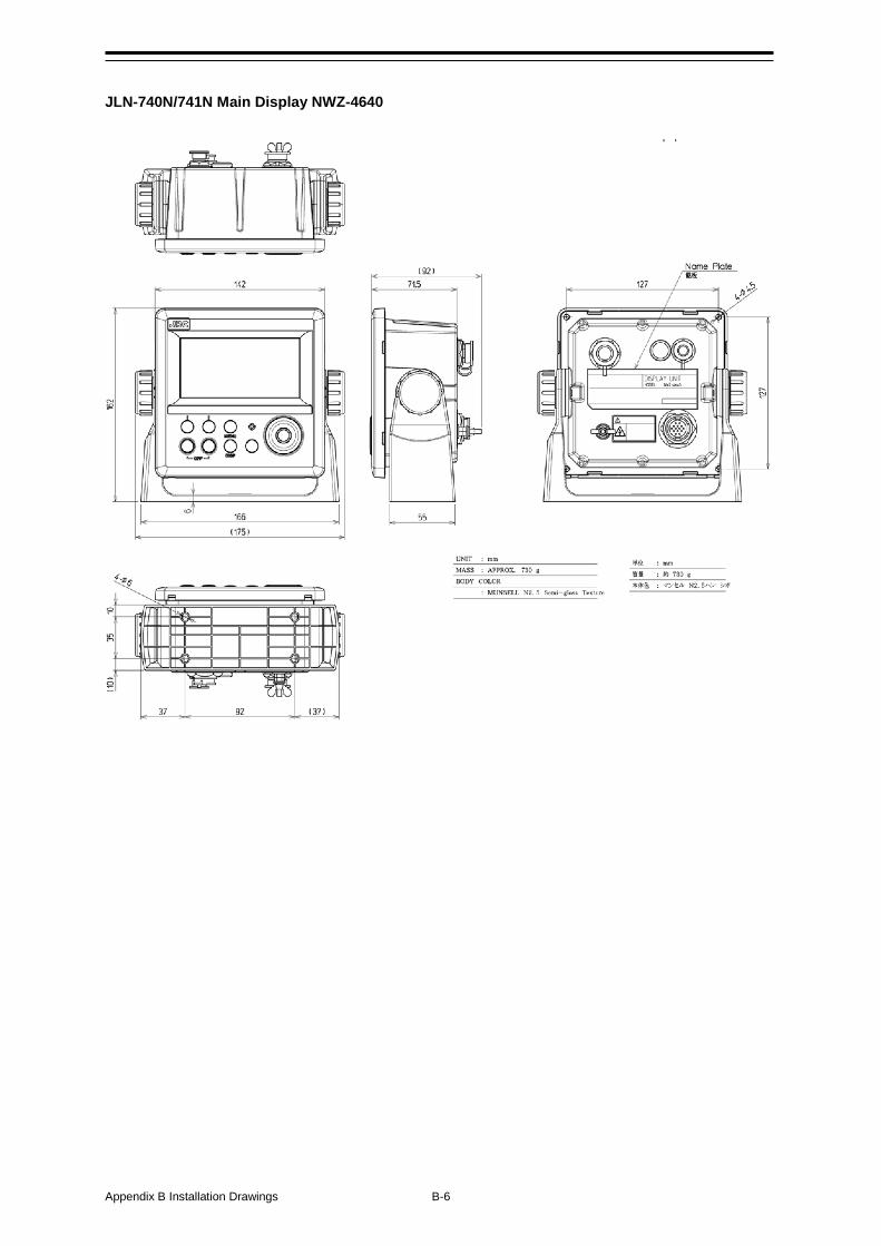
Appendix B Installation Drawings B-6
JLN-740N/741N Main Display NWZ-4640
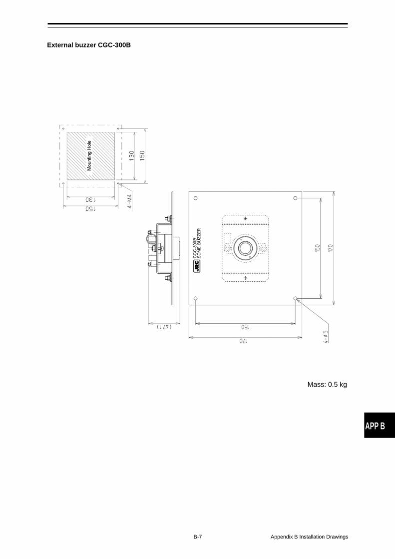
B-7 Appendix B Installation Drawings
APP B
External buzzer CGC-300B
Mass: 0.5 kg
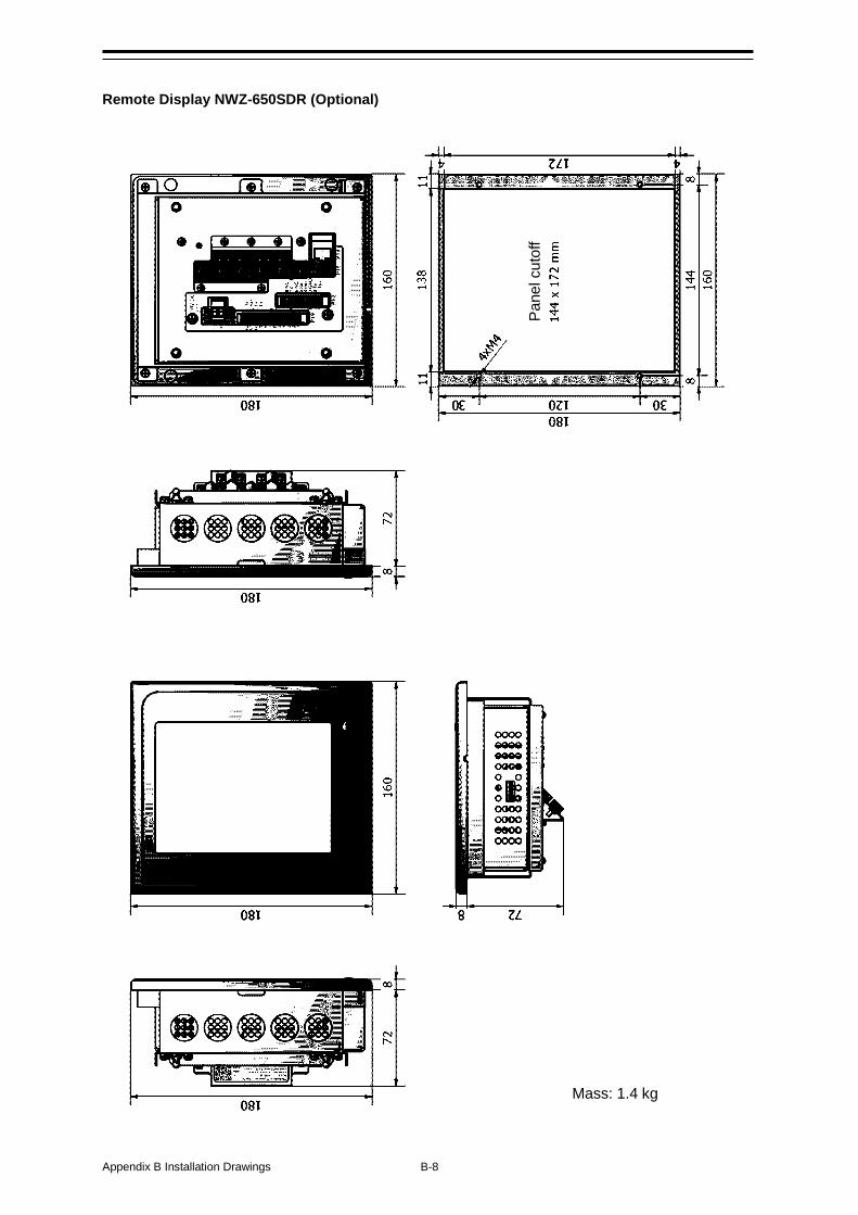
Appendix B Installation Drawings B-8
Remote Display NWZ-650SDR (Optional)
Pane
l cut
off
Mass: 1.4 kg
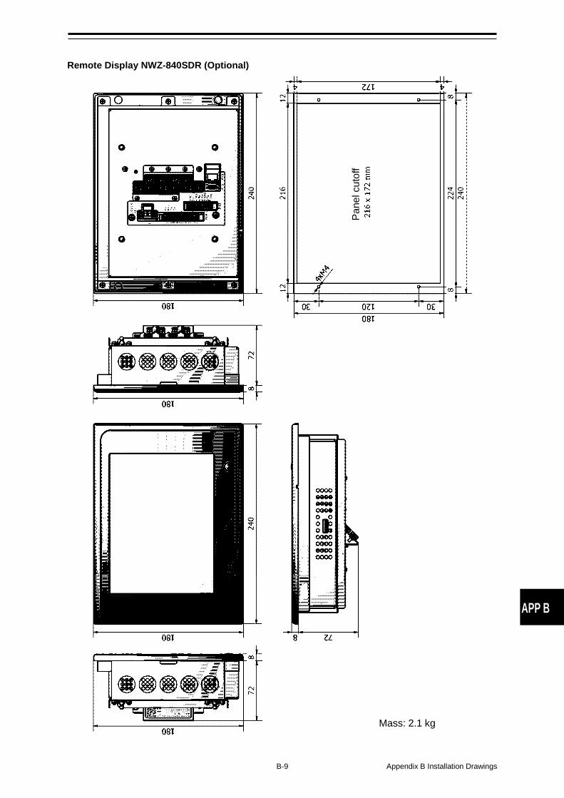
B-9 Appendix B Installation Drawings
APP B
Remote Display NWZ-840SDR (Optional)
Pane
l cut
off
Mass: 2.1 kg
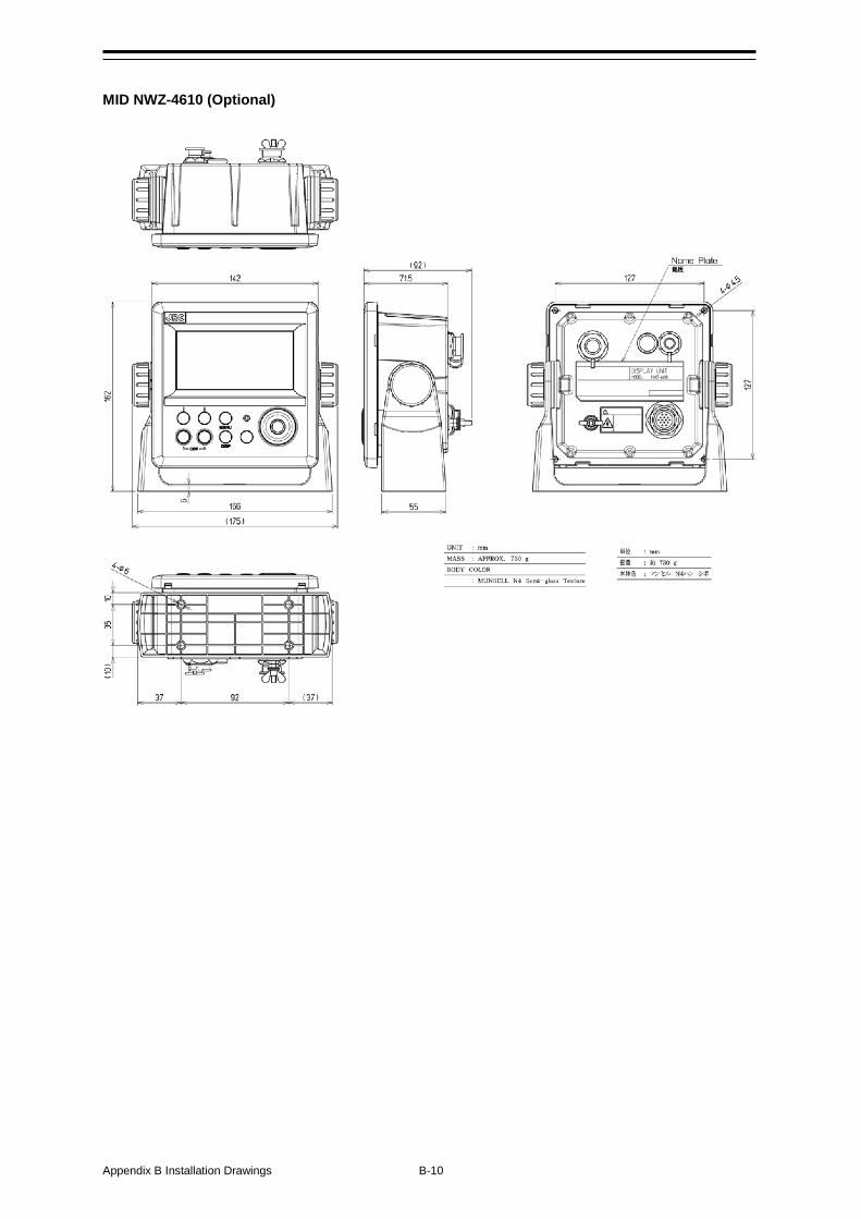
Appendix B Installation Drawings B-10
MID NWZ-4610 (Optional)
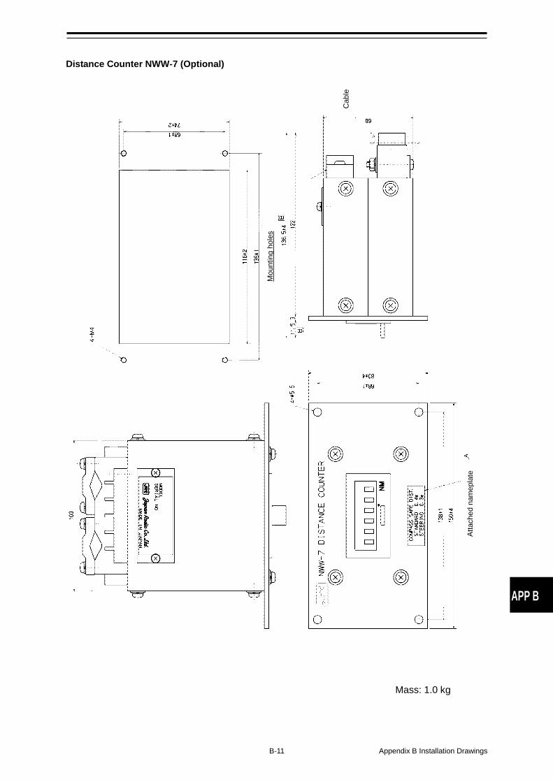
B-11 Appendix B Installation Drawings
APP B
Distance Counter NWW-7 (Optional)
Mou
ntin
g ho
les
Cab
le
Atta
ched
nam
epla
te
Mass: 1.0 kg
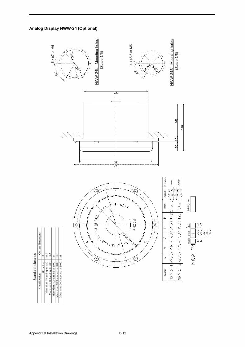
Appendix B Installation Drawings B-12
Analog Display NWW-24 (Optional)
Cl
assi
ficat
ion
Out
line
dim
ensi
ons
30 o
r les
s ±1
M
ore
than
30
and
up to
120
±1
.5
Mor
e th
an 1
20 a
nd u
p to
400
±2
.5
Mor
e th
an 4
00 a
nd u
p to
100
0 ±4
M
ore
than
100
0 an
d up
to 2
000
±6
Mor
e th
an 2
000
and
up to
300
0 ±8
6 x φ7
or M
6
4 x φ5
.5 o
r M5
NW
W-2
4L
Mou
ntin
g ho
les
(Sca
le 1
/5)
NW
W-2
4S
Mou
ntin
g ho
les
(Sca
le 1
/5)
E. L
. pla
te
Scal
e M
ass.
M
odel
E. L
.
plat
e Sc
ale
Mod
el
Pain
ting
colo
r
Gre
en
Ora
nge
Stan
dard
tole
ranc
e
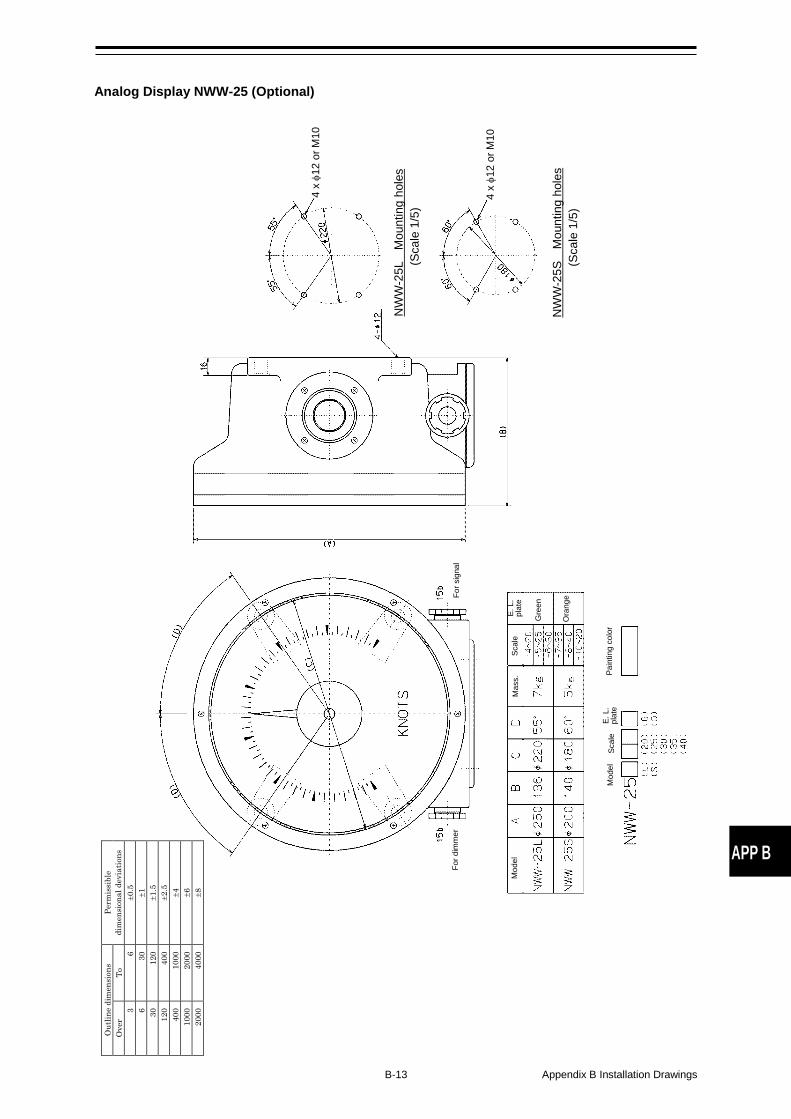
B-13 Appendix B Installation Drawings
APP B
Analog Display NWW-25 (Optional)
4 x φ1
2 or
M10
4 x φ1
2 or
M10
NW
W-2
5L
Mou
ntin
g ho
les
(Sca
le 1
/5)
NW
W-2
5S
Mou
ntin
g ho
les
(Sca
le 1
/5)
Mod
el
Mas
s.
Scal
e
Scal
e E.
L.
pl
ate
Gre
en
Ora
nge
E. L
.
plat
e M
odel
For d
imm
er
For s
igna
l
Pain
ting
colo
r
O
utlin
e di
men
sion
s Pe
rmis
sibl
e di
men
sion
al d
evia
tions
O
ver
To
3 6
±0.5
6
30
±1
30
120
±1.5
12
0 40
0 ±2
.5
400
1000
±4
10
00
2000
±6
20
00
4000
±8
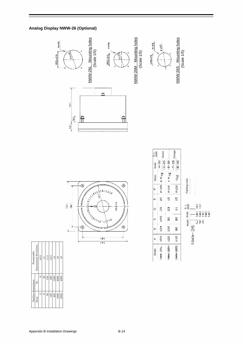
Appendix B Installation Drawings B-14
Analog Display NWW-26 (Optional)
NW
W-2
6L
Mou
ntin
g ho
les
(Sca
le 1
/5)
NW
W-2
6M
Mou
ntin
g ho
les
(Sca
le 1
/5)
NW
W-2
6S
Mou
ntin
g ho
les
(Sca
le 1
/5)
Mod
el
Mas
s.
Scal
e E.
L.
pl
ate
Gre
en
Ora
nge
Pain
ting
colo
r M
odel
Sc
ale
E. L
.
plat
e
O
utlin
e di
men
sion
s Pe
rmis
sibl
e di
men
sion
al d
evia
tions
O
ver
To
3 6
±0.5
6
30
±1
30
120
±1.5
12
0 40
0 ±2
.5
400
1000
±4
10
00
2000
±6
20
00
4000
±8
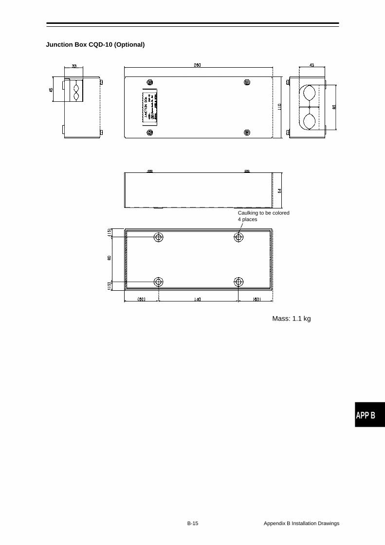
B-15 Appendix B Installation Drawings
APP B
Junction Box CQD-10 (Optional)
Caulking to be colored 4 places
Mass: 1.1 kg

Appendix B Installation Drawings B-16
Dimmer Unit NCM-227 (Optional)
Outline dimensions Permissible dimensional deviations Over To
3 6 ±0.5 6 30 ±1
30 120 ±1.5 120 400 ±2.5 400 1000 ±4
1000 2000 ±6 2000 4000 ±8
Terminal board
Mounting hole size
Painting color 7.5BG7/2 Mass. 0.5 kg
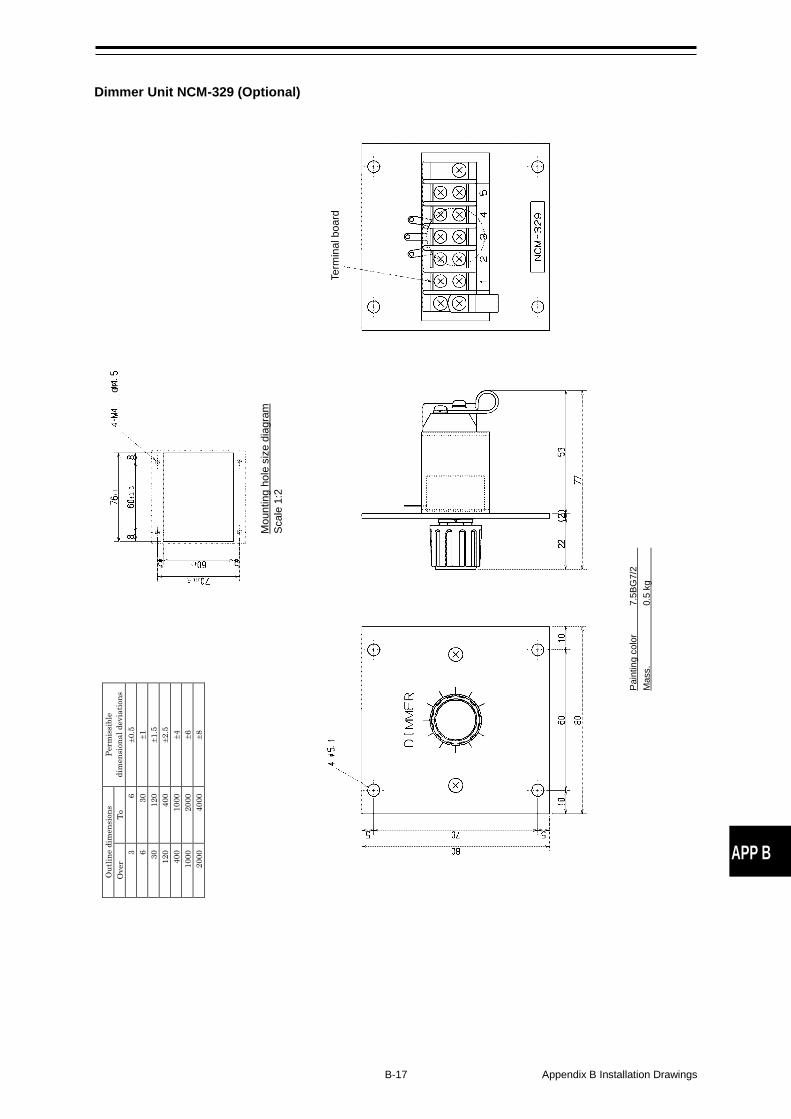
B-17 Appendix B Installation Drawings
APP B
Dimmer Unit NCM-329 (Optional)
Pain
ting
colo
r 7.
5BG
7/2
Mas
s.
0.5
kg
Term
inal
boa
rd
or
Mou
ntin
g ho
le s
ize
diag
ram
Sc
ale
1:2
O
utlin
e di
men
sion
s Pe
rmis
sibl
e di
men
sion
al d
evia
tions
O
ver
To
3 6
±0.5
6
30
±1
30
120
±1.5
12
0 40
0 ±2
.5
400
1000
±4
10
00
2000
±6
20
00
4000
±8
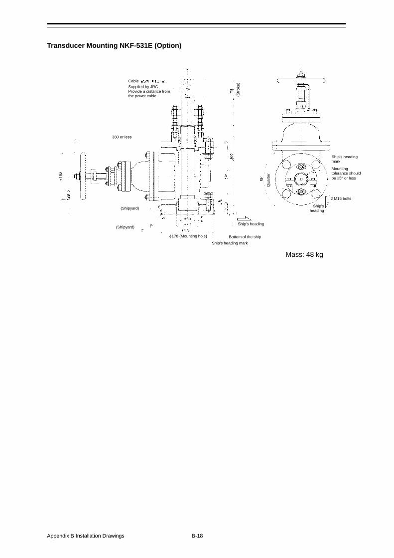
Appendix B Installation Drawings B-18
Transducer Mounting NKF-531E (Option)
Cable Supplied by JRC
Provide a distance from the power cable.
380 or less
(Shipyard)
(Shipyard)
(Stro
ke)
φ178 (Mounting hole) Ship’s heading mark
Bottom of the ship
Ship’s heading
Ship’s heading mark
Ship’s heading
Qua
rter
Mounting tolerance should be ±5° or less
2 M16 bolts
Mass: 48 kg
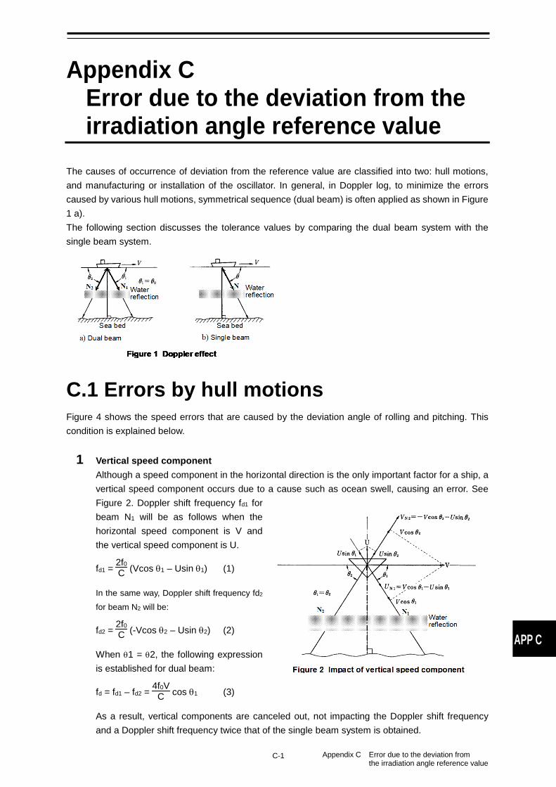
C-1 Appendix C Error due to the deviation from the irradiation angle reference value
APP C
Appendix C Error due to the deviation from the irradiation angle reference value
The causes of occurrence of deviation from the reference value are classified into two: hull motions, and manufacturing or installation of the oscillator. In general, in Doppler log, to minimize the errors caused by various hull motions, symmetrical sequence (dual beam) is often applied as shown in Figure 1 a). The following section discusses the tolerance values by comparing the dual beam system with the single beam system.
C.1 Errors by hull motions Figure 4 shows the speed errors that are caused by the deviation angle of rolling and pitching. This condition is explained below.
1 Vertical speed component Although a speed component in the horizontal direction is the only important factor for a ship, a vertical speed component occurs due to a cause such as ocean swell, causing an error. See Figure 2. Doppler shift frequency fd1 for beam N1 will be as follows when the horizontal speed component is V and the vertical speed component is U.
fd1 = 2f0C (Vcos θ1 – Usin θ1) (1)
In the same way, Doppler shift frequency fd2
for beam N2 will be:
fd2 = 2f0C (-Vcos θ2 – Usin θ2) (2)
When θ1 = θ2, the following expression is established for dual beam:
fd = fd1 – fd2 = 4f0VC cos θ1 (3)
As a result, vertical components are canceled out, not impacting the Doppler shift frequency and a Doppler shift frequency twice that of the single beam system is obtained.
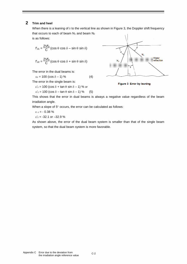
C-2 Appendix C Error due to the deviation from the irradiation angle reference value
2 Trim and heel When there is a leaning of δ to the vertical line as shown in Figure 3, the Doppler shift frequency that occurs to each of beam N1 and beam N2 is as follows:
f'd1 = 2Vf0C (cos θ cos δ – sin θ sin δ)
f'd2 = 2Vf0C (cos θ cos δ + sin θ sin δ)
The error in the dual beams is: εδ = 100 (cos δ – 1) % (4)
The error in the single beam is: ε'δ = 100 (cos δ + tan θ sin δ – 1) % or
ε'δ = 100 (cos δ – tan θ sin δ – 1) % (5) This shows that the error in dual beams is always a negative value regardless of the beam irradiation angle. When a slope of 5° occurs, the error can be calculated as follows: ε δ = - 0.38 % ε'δ = -32.1 or –32.9 % As shown above, the error of the dual beam system is smaller than that of the single beam system, so that the dual beam system is more favorable.
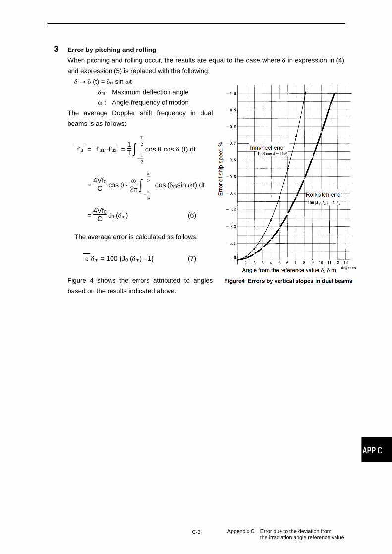
C-3 Appendix C Error due to the deviation from the irradiation angle reference value
APP C
3 Error by pitching and rolling When pitching and rolling occur, the results are equal to the case where δ in expression in (4) and expression (5) is replaced with the following: δ → δ (t) = δm sin ωt
δm: Maximum deflection angle ω : Angle frequency of motion
The average Doppler shift frequency in dual beams is as follows:
f'd = f'd1–f'd2 = 1T ∫−
2T
2T
cos θ cos δ (t) dt
= 4Vf0C cos θ ⋅ ω2π ∫
ωπ
ωπ
−
cos (δmsin ωt) dt
= 4Vf0C J0 (δm) (6)
The average error is calculated as follows.
ε δm = 100 {J0 (δm) –1} (7)
Figure 4 shows the errors attributed to angles based on the results indicated above.

C-4 Appendix C Error due to the deviation from the irradiation angle reference value
(This page intentionally left blank)
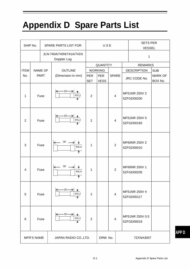
D-1 Appendix D Spare Parts List
APP D
Appendix D Spare Parts List
SHIP No. SPARE PARTS LIST FOR U S E SETS PER VESSEL
JLN-740A/740N/741A/741N
Doppler Log 1
ITEM No.
NAME OF PART
OUTLINE (Dimension in mm)
QUANTITY REMARKS WORKING
SPARE DESCRIPTION SUB
MARK OF BOX No.
PER SET
PER VESS
JRC CODE No.
1 Fuse
2 4 MF51NR 250V 2 5ZFGD00200
2 Fuse
2 4 MF51NR 250V 5 5ZFGD00183
3 Fuse
1 2 MF60NR 250V 2 5ZFGD00010
4 Fuse
1 2 MF60NR 250V 1 5ZFGD00205
5 Fuse
2 4 MF51NR 250V 4 5ZFGD00117
6 Fuse
2 4 MF51NR 250V 0.5 5ZFGD00019
MFR’S NAME JAPAN RADIO CO.,LTD. DRW. No. 7ZXNA3007
20 Φ5.2
20 Φ5.2
30
Φ6.4
30
Φ6.4
20 Φ5.2
20 Φ5.2

Appendix D Spare Parts List D-2
(This page intentionally left blank)


ISO 9001, ISO 14001 Certified
OCT. 2019 Edition 3CODE No.7ZPNA3208
Not use the asbestos
For further information,contact:
URL Head office : http://www.jrc.co.jp/eng/
Marine Service Department
1-7-32 Tatsumi, Koto-ku, Tokyo 135-0053, Japan
: +81-50-3786-9201e-mailOne-call
General
1
Function of Each Components
2
Operation Method (JLN-740A/741A)
3
Menu Settings and Configurations (JLN-740A/741A)
4
Operation Method (JLN-740N/741N)
5
Menu Settings and Configurations (JLN-740N/741N)
6
Operation Method (Option)
7
Setting by Using Menus (Option)
8
Installation Method
9
Maintenance and Inspection
10
After-Sales Service
11
Disposal
12
Specification
13
Menu list APP A
Installation Drawings APP B
Error due to the deviation from the irradiation angle reference value
APP C
Spare Parts List APP D
JLN-740A/740N JLN-741A/741N DOPPLER LOG
Instruction Manual