Embed Size (px)
Citation preview

059411-00 Rev. A
Installation and Operation Manual
Oil Tank MonitorMSI OTM
2 MSI OTM Installation and Operation Manual
Contents
059411-00 Rev. A Heat‐Timer Corp.
Controls, Indicators, and Connections. . . . . . . . . . . . . . . . . . . . . 3Specifications . . . . . . . . . . . . . . . . . . . . . . . . . . . . . . . . . . . . . . . . . 4Installation Instructions . . . . . . . . . . . . . . . . . . . . . . . . . . . . . . . . 5
Required Materials (Not Supplied) . . . . . . . . . . . . . . . . . . . . . 5Mounting the MSI OTM . . . . . . . . . . . . . . . . . . . . . . . . . . . . . . 5Connecting the Wiring . . . . . . . . . . . . . . . . . . . . . . . . . . . . . . . 7
Startup Instructions . . . . . . . . . . . . . . . . . . . . . . . . . . . . . . . . . . . . 9Detailed Operation . . . . . . . . . . . . . . . . . . . . . . . . . . . . . . . . . . . 10
Control Theory . . . . . . . . . . . . . . . . . . . . . . . . . . . . . . . . . . . . 10Programming the OTM . . . . . . . . . . . . . . . . . . . . . . . . . . . . . 10OTM Menu Options . . . . . . . . . . . . . . . . . . . . . . . . . . . . . . . . 11
OTM Menu Map . . . . . . . . . . . . . . . . . . . . . . . . . . . . . . . . 11Troubleshooting . . . . . . . . . . . . . . . . . . . . . . . . . . . . . . . . . . . . . . 12Connection Diagram . . . . . . . . . . . . . . . . . . . . . . . . . . . . . . . . . . 13Notes . . . . . . . . . . . . . . . . . . . . . . . . . . . . . . . . . . . . . . . . . . . . . . . 14
Controls, Indicators, and Connections 3
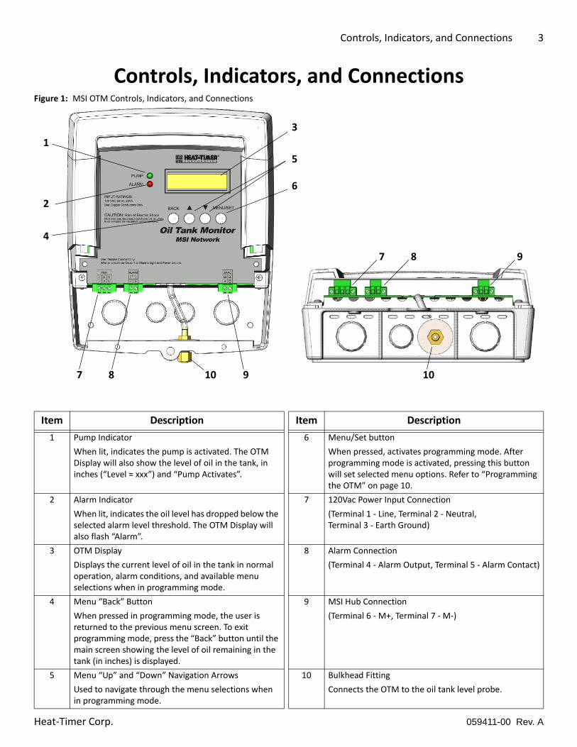
Controls, Indicators, and ConnectionsFigure 1: MSI OTM Controls, Indicators, and Connections
Item Description Item Description
1 Pump Indicator
When lit, indicates the pump is activated. The OTM Display will also show the level of oil in the tank, in inches (“Level = xxx”) and “Pump Activates”.
6 Menu/Set button
When pressed, activates programming mode. After programming mode is activated, pressing this button will set selected menu options. Refer to “Programming the OTM” on page 10.
2 Alarm Indicator
When lit, indicates the oil level has dropped below the selected alarm level threshold. The OTM Display will also flash “Alarm”.
7 120Vac Power Input Connection
(Terminal 1 ‐ Line, Terminal 2 ‐ Neutral, Terminal 3 ‐ Earth Ground)
3 OTM Display
Displays the current level of oil in the tank in normal operation, alarm conditions, and available menu selections when in programming mode.
8 Alarm Connection
(Terminal 4 ‐ Alarm Output, Terminal 5 ‐ Alarm Contact)
4 Menu “Back” Button
When pressed in programming mode, the user is returned to the previous menu screen. To exit programming mode, press the “Back” button until the main screen showing the level of oil remaining in the tank (in inches) is displayed.
9 MSI Hub Connection
(Terminal 6 ‐ M+, Terminal 7 ‐ M‐)
5 Menu “Up” and “Down” Navigation Arrows
Used to navigate through the menu selections when in programming mode.
10 Bulkhead Fitting
Connects the OTM to the oil tank level probe.
1
3
5
6
2
4
987
987 1010
059411-00 Rev. AHeat‐Timer Corp.
4 MSI OTM Installation and Operation Manual
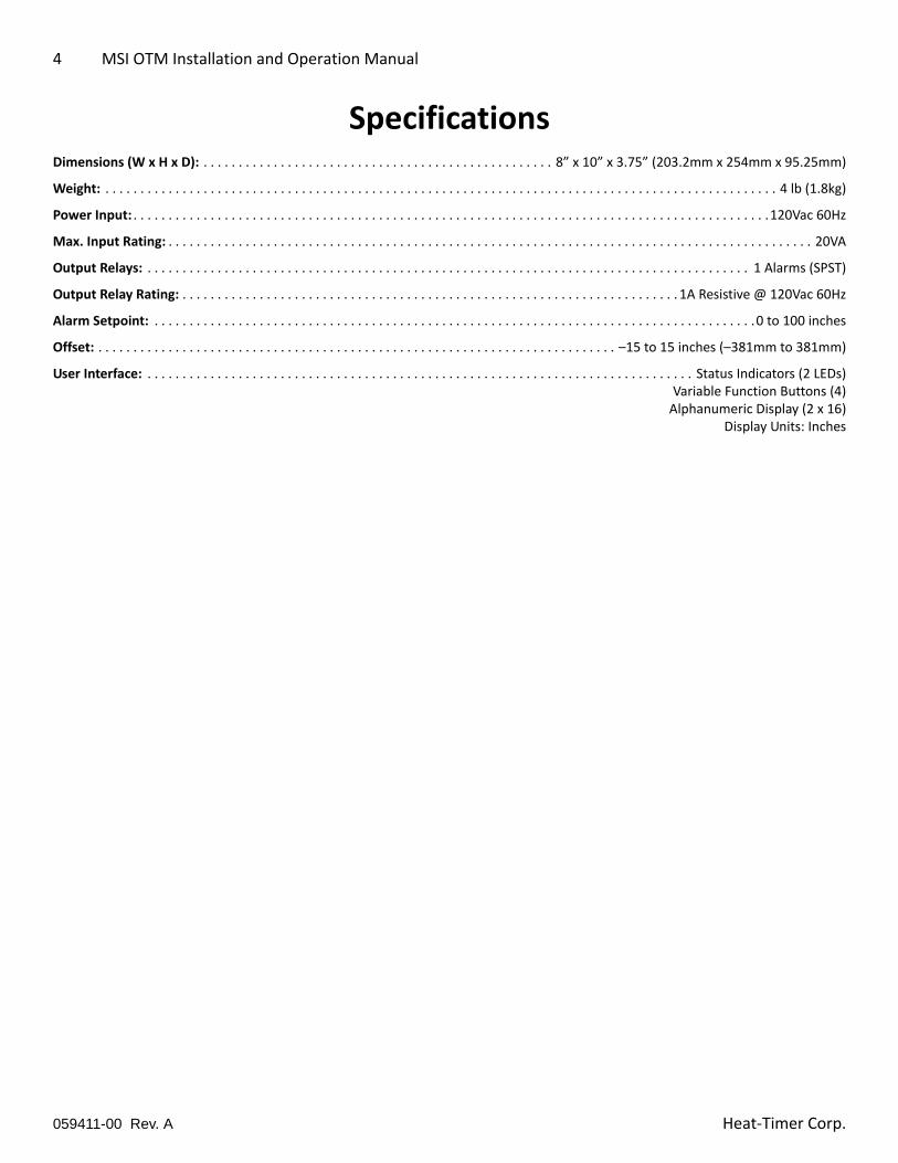
SpecificationsDimensions (W x H x D): . . . . . . . . . . . . . . . . . . . . . . . . . . . . . . . . . . . . . . . . . . . . . . . . . . 8” x 10” x 3.75” (203.2mm x 254mm x 95.25mm)
Weight: . . . . . . . . . . . . . . . . . . . . . . . . . . . . . . . . . . . . . . . . . . . . . . . . . . . . . . . . . . . . . . . . . . . . . . . . . . . . . . . . . . . . . . . . . . . . . . . . 4 lb (1.8kg)
Power Input: . . . . . . . . . . . . . . . . . . . . . . . . . . . . . . . . . . . . . . . . . . . . . . . . . . . . . . . . . . . . . . . . . . . . . . . . . . . . . . . . . . . . . . . . . . .120Vac 60Hz
Max. Input Rating: . . . . . . . . . . . . . . . . . . . . . . . . . . . . . . . . . . . . . . . . . . . . . . . . . . . . . . . . . . . . . . . . . . . . . . . . . . . . . . . . . . . . . . . . . . . . 20VA
Output Relays: . . . . . . . . . . . . . . . . . . . . . . . . . . . . . . . . . . . . . . . . . . . . . . . . . . . . . . . . . . . . . . . . . . . . . . . . . . . . . . . . . . . . . . 1 Alarms (SPST)
Output Relay Rating: . . . . . . . . . . . . . . . . . . . . . . . . . . . . . . . . . . . . . . . . . . . . . . . . . . . . . . . . . . . . . . . . . . . . . . . 1A Resistive @ 120Vac 60Hz
Alarm Setpoint: . . . . . . . . . . . . . . . . . . . . . . . . . . . . . . . . . . . . . . . . . . . . . . . . . . . . . . . . . . . . . . . . . . . . . . . . . . . . . . . . . . . . . .0 to 100 inches
Offset: . . . . . . . . . . . . . . . . . . . . . . . . . . . . . . . . . . . . . . . . . . . . . . . . . . . . . . . . . . . . . . . . . . . . . . . . . . –15 to 15 inches (–381mm to 381mm)
User Interface: . . . . . . . . . . . . . . . . . . . . . . . . . . . . . . . . . . . . . . . . . . . . . . . . . . . . . . . . . . . . . . . . . . . . . . . . . . . . . . Status Indicators (2 LEDs)Variable Function Buttons (4)Alphanumeric Display (2 x 16)
Display Units: Inches
059411-00 Rev. A Heat‐Timer Corp.
Installation Instructions 5
Installation InstructionsThis section provides the installation instructions for the MSI OTM.
The installation process consists of the following basic steps:
1. Selecting appropriate locations and mounting the device(s).
2. Connecting power and communications wiring.
3. Performing an initial startup and configuration of the system.
Required Materials (Not Supplied)The following materials/tools are required for installation, but are not supplied:
• General tool kit (screwdrivers, wrenches, wire strippers, power drill, etc.)
• 1/4” copper compression tee
• 1/4” copper tubing (soft)
• 18 AWG multi‐conductor, shielded twisted‐pair cable (Belden p/n 8760 or equivalent #18/2 cable) – used for the 24Vac OTM to MSI Hub connection
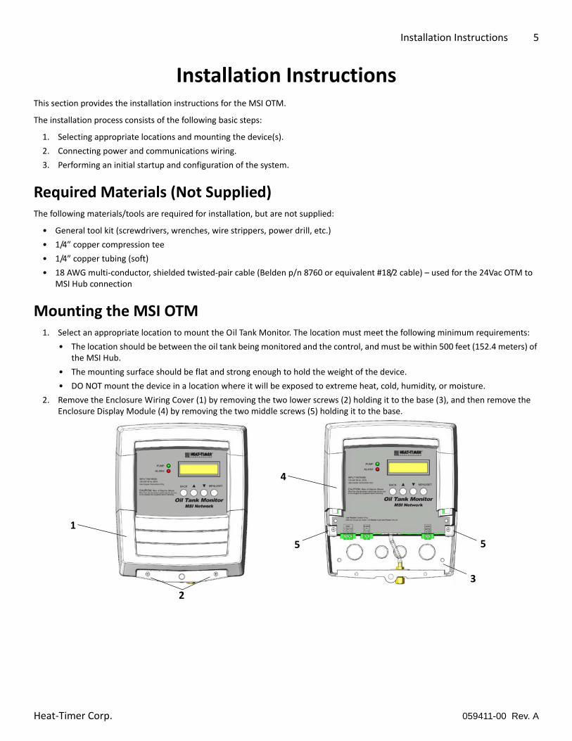
Mounting the MSI OTM1. Select an appropriate location to mount the Oil Tank Monitor. The location must meet the following minimum requirements:
• The location should be between the oil tank being monitored and the control, and must be within 500 feet (152.4 meters) of the MSI Hub.
• The mounting surface should be flat and strong enough to hold the weight of the device.
• DO NOT mount the device in a location where it will be exposed to extreme heat, cold, humidity, or moisture.
2. Remove the Enclosure Wiring Cover (1) by removing the two lower screws (2) holding it to the base (3), and then remove the Enclosure Display Module (4) by removing the two middle screws (5) holding it to the base.
1
2
4
5 5
3
059411-00 Rev. AHeat‐Timer Corp.
6 MSI OTM Installation and Operation Manual
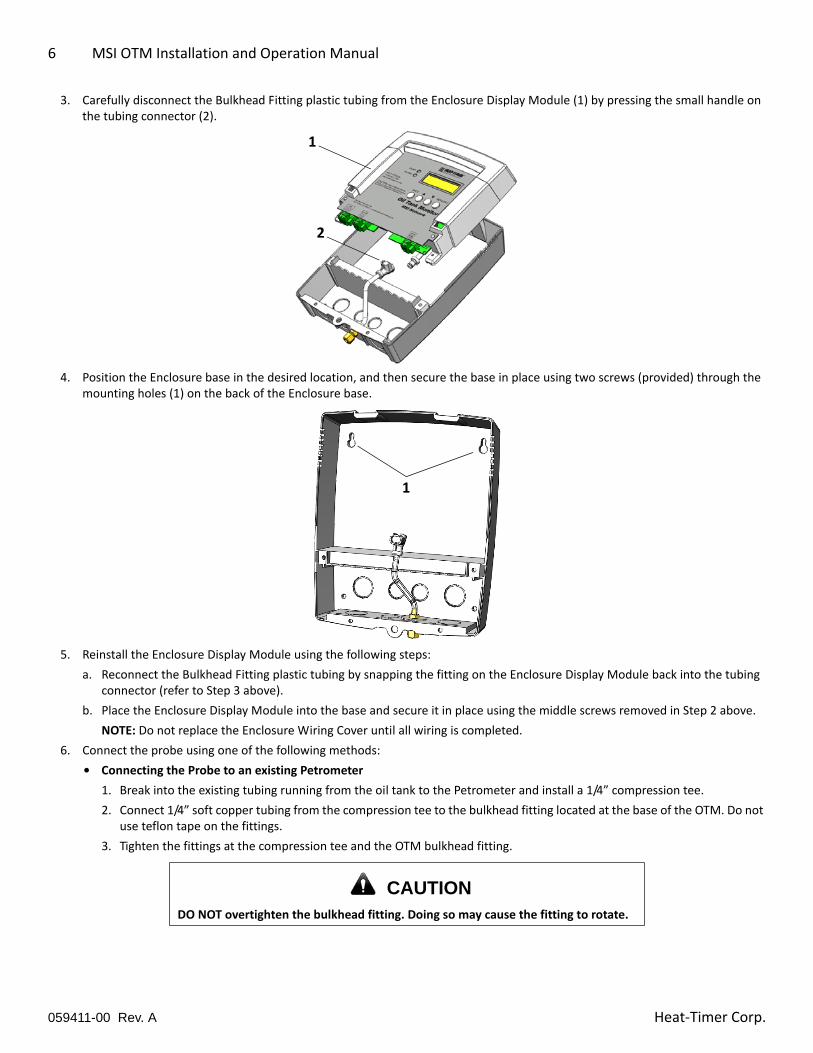
3. Carefully disconnect the Bulkhead Fitting plastic tubing from the Enclosure Display Module (1) by pressing the small handle on the tubing connector (2).
4. Position the Enclosure base in the desired location, and then secure the base in place using two screws (provided) through the mounting holes (1) on the back of the Enclosure base.
5. Reinstall the Enclosure Display Module using the following steps:
a. Reconnect the Bulkhead Fitting plastic tubing by snapping the fitting on the Enclosure Display Module back into the tubing connector (refer to Step 3 above).
b. Place the Enclosure Display Module into the base and secure it in place using the middle screws removed in Step 2 above.
NOTE: Do not replace the Enclosure Wiring Cover until all wiring is completed.
6. Connect the probe using one of the following methods:
• Connecting the Probe to an existing Petrometer
1. Break into the existing tubing running from the oil tank to the Petrometer and install a 1/4” compression tee.
2. Connect 1/4” soft copper tubing from the compression tee to the bulkhead fitting located at the base of the OTM. Do not use teflon tape on the fittings.
3. Tighten the fittings at the compression tee and the OTM bulkhead fitting.
CAUTIONDO NOT overtighten the bulkhead fitting. Doing so may cause the fitting to rotate.
2
1
1
059411-00 Rev. A Heat‐Timer Corp.
Installation Instructions 7
• Connecting the Probe directly to the Oil Tank
1. Using 1/4” soft copper tubing, connect one end of the tubing to the bottom of the oil tank, and then connect the other end of the tubing to the bulkhead fitting located at the base of the OTM. Do not use teflon tape on the fittings.
2. Tighten the OTM bulkhead fitting.
7. Continue to “Connecting the Wiring” on page 7 when all devices have been mounted.
Connecting the Wiring
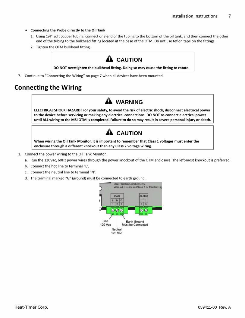
1. Connect the power wiring to the Oil Tank Monitor.
a. Run the 120Vac, 60Hz power wires through the power knockout of the OTM enclosure. The left‐most knockout is preferred.
b. Connect the hot line to terminal “L”.
c. Connect the neutral line to terminal “N”.
d. The terminal marked “G” (ground) must be connected to earth ground.
CAUTIONDO NOT overtighten the bulkhead fitting. Doing so may cause the fitting to rotate.
WARNINGELECTRICAL SHOCK HAZARD! For your safety, to avoid the risk of electric shock, disconnect electrical power to the device before servicing or making any electrical connections. DO NOT re‐connect electrical power until ALL wiring to the MSI OTM is completed. Failure to do so may result in severe personal injury or death.
CAUTIONWhen wiring the Oil Tank Monitor, it is important to remember that Class 1 voltages must enter the enclosure through a different knockout than any Class 2 voltage wiring.
059411-00 Rev. AHeat‐Timer Corp.
8 MSI OTM Installation and Operation Manual
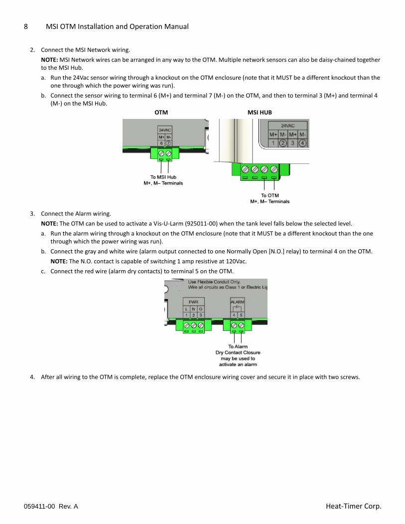
2. Connect the MSI Network wiring.
NOTE: MSI Network wires can be arranged in any way to the OTM. Multiple network sensors can also be daisy‐chained together to the MSI Hub.
a. Run the 24Vac sensor wiring through a knockout on the OTM enclosure (note that it MUST be a different knockout than the one through which the power wiring was run).
b. Connect the sensor wiring to terminal 6 (M+) and terminal 7 (M‐) on the OTM, and then to terminal 3 (M+) and terminal 4 (M‐) on the MSI Hub.
3. Connect the Alarm wiring.
NOTE: The OTM can be used to activate a Vis‐U‐Larm (925011‐00) when the tank level falls below the selected level.
a. Run the alarm wiring through a knockout on the OTM enclosure (note that it MUST be a different knockout than the one through which the power wiring was run).
b. Connect the gray and white wire (alarm output connected to one Normally Open [N.O.] relay) to terminal 4 on the OTM.
NOTE: The N.O. contact is capable of switching 1 amp resistive at 120Vac.
c. Connect the red wire (alarm dry contacts) to terminal 5 on the OTM.
4. After all wiring to the OTM is complete, replace the OTM enclosure wiring cover and secure it in place with two screws.
OTM MSI HUB
059411-00 Rev. A Heat‐Timer Corp.
Startup Instructions 9
Startup InstructionsUse the following steps to perform an initial configuration of the MSI OTM.
1. Connect power to the Oil Tank Monitor. The following sequence of events will occur:
a. The OTM displays “Heat-Timer Corp. V 1.00 2013” followed by “Oil Tank Level Monitor”.
b. The OTM displays “Level= [xxx]” where [xxx] is the oil level in the tank, in inches.
c. After the oil level is displayed, the internal oil pump turns on to update the oil level reading. The OTM displays “Pump activates”.
d. After the pump finishes, the OTM updates the display to show the current oil level in the tank.
2. Enter programming mode and configure the following settings (refer to “Programming the OTM” on page 10 for information):
• Oil Type – Select the oil type used in the system (Oil #2, Oil #4, or Oil #6).
• Bottom Offset – If a petrometer is installed, set the Bottom Offset so the OTM and petrometer display the same oil level.
059411-00 Rev. AHeat‐Timer Corp.
10 MSI OTM Installation and Operation Manual
Detailed Operation
Control TheoryThe Oil Tank Monitor measures and displays the number of inches of oil in a tank, and can activate an alarm if the oil level falls below a user‐configured number of inches. The unit is designed to transmit the tank level (via the MSI Hub) to the Platinum Control, which then sends the information to the Internet Control Management System (ICMS). This allows remote users to monitor the level of the tank and send out alarms if the tank level is outside the desired range.
The Oil Tank Monitor has a pump for automatic pressure compensation. An internal timer energizes the pump at regular intervals to ensure correct operation. The pump can also be programmed to activate immediately for testing or after maintenance.
The Oil Tank Monitor’s internal programming mode allows adjustment of the Alarm value (in inches) and provides an offset for tube placement in the oil tank. Once programmed, these values will not be lost if power is interrupted or lost. The program values are displayed, allowing precise adjustment for each setting.
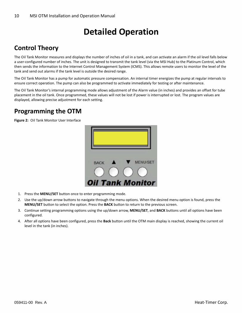
Programming the OTMFigure 2: Oil Tank Monitor User Interface
1. Press the MENU/SET button once to enter programming mode.
2. Use the up/down arrow buttons to navigate through the menu options. When the desired menu option is found, press the MENU/SET button to select the option. Press the BACK button to return to the previous screen.
3. Continue setting programming options using the up/down arrow, MENU/SET, and BACK buttons until all options have been configured.
4. After all options have been configured, press the Back button until the OTM main display is reached, showing the current oil level in the tank (in inches).
059411-00 Rev. A Heat‐Timer Corp.
Detailed Operation 11
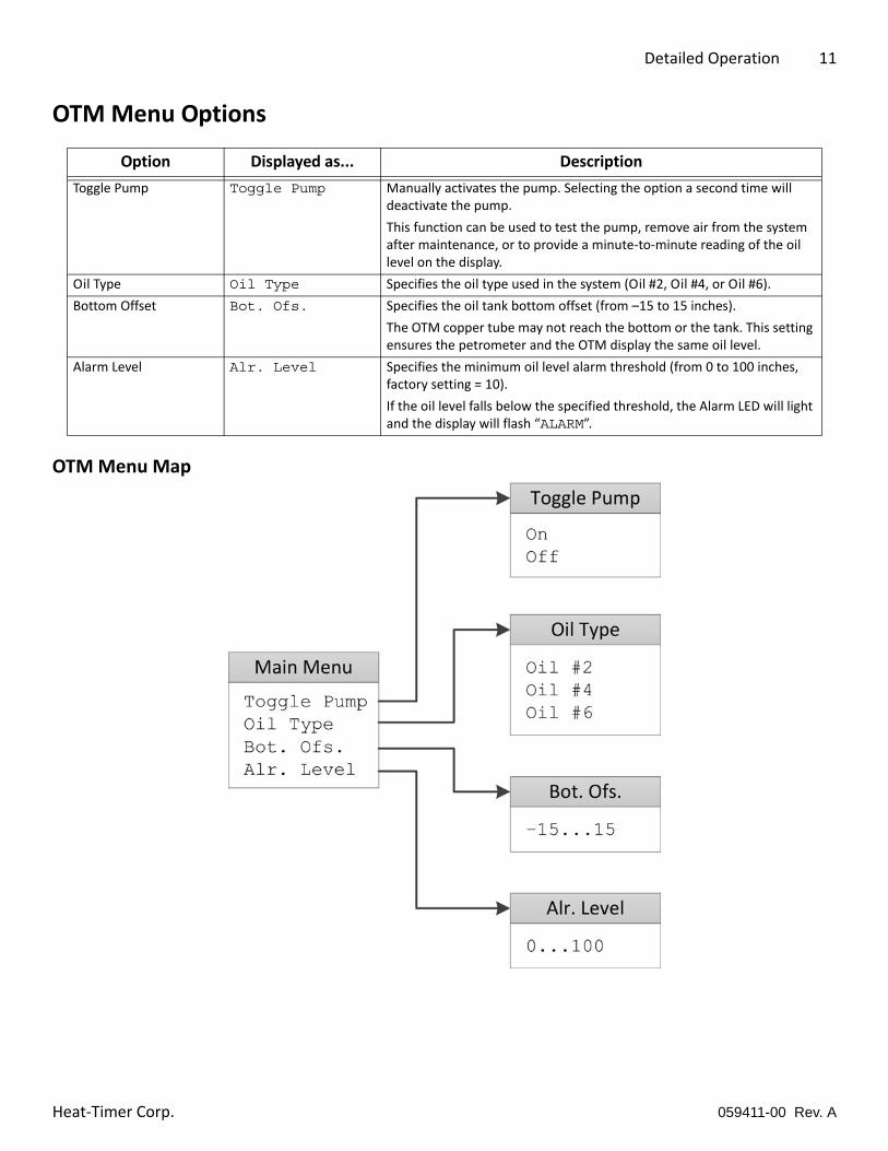
OTM Menu Options
OTM Menu Map
Option Displayed as... Description
Toggle Pump Toggle Pump Manually activates the pump. Selecting the option a second time will deactivate the pump.
This function can be used to test the pump, remove air from the system after maintenance, or to provide a minute‐to‐minute reading of the oil level on the display.
Oil Type Oil Type Specifies the oil type used in the system (Oil #2, Oil #4, or Oil #6).
Bottom Offset Bot. Ofs. Specifies the oil tank bottom offset (from –15 to 15 inches).
The OTM copper tube may not reach the bottom or the tank. This setting ensures the petrometer and the OTM display the same oil level.
Alarm Level Alr. Level Specifies the minimum oil level alarm threshold (from 0 to 100 inches, factory setting = 10).
If the oil level falls below the specified threshold, the Alarm LED will light and the display will flash “ALARM”.
059411-00 Rev. AHeat‐Timer Corp.
12 MSI OTM Installation and Operation Manual
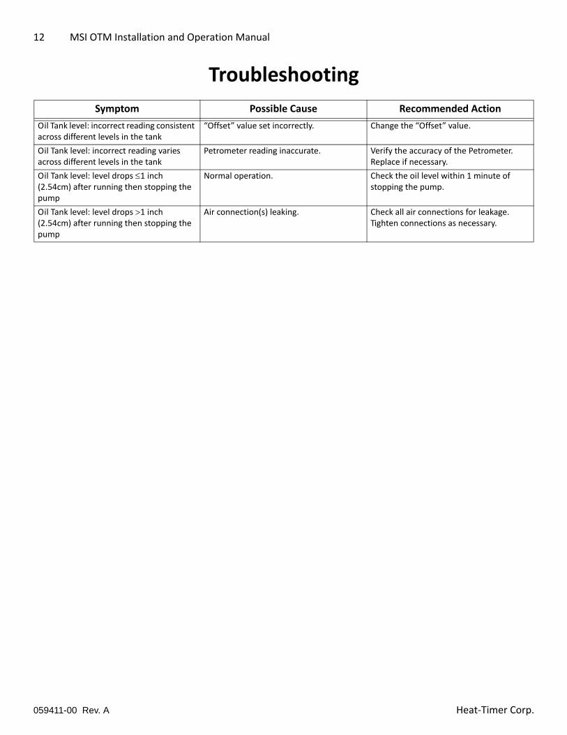
Troubleshooting
Symptom Possible Cause Recommended Action
Oil Tank level: incorrect reading consistent across different levels in the tank
“Offset” value set incorrectly. Change the “Offset” value.
Oil Tank level: incorrect reading varies across different levels in the tank
Petrometer reading inaccurate. Verify the accuracy of the Petrometer. Replace if necessary.
Oil Tank level: level drops 1 inch (2.54cm) after running then stopping the pump
Normal operation. Check the oil level within 1 minute of stopping the pump.
Oil Tank level: level drops 1 inch (2.54cm) after running then stopping the pump
Air connection(s) leaking. Check all air connections for leakage. Tighten connections as necessary.
059411-00 Rev. A Heat‐Timer Corp.
Connection Diagram 13
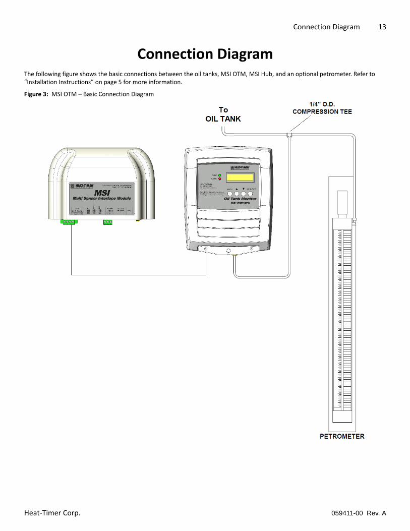
Connection DiagramThe following figure shows the basic connections between the oil tanks, MSI OTM, MSI Hub, and an optional petrometer. Refer to “Installation Instructions” on page 5 for more information.
Figure 3: MSI OTM – Basic Connection Diagram
059411-00 Rev. AHeat‐Timer Corp.

14 MSI OTM Installation and Operation Manual
Notes
059411-00 Rev. A Heat‐Timer Corp.

Notes 15
Notes
059411-00 Rev. AHeat‐Timer Corp.

20 New Dutch Lane, Fairfield, NJ 07004 973-575-4004 • Fax 973-575-4052 • http://www.heat-timer.com
WARRANTIES AND LIMITATIONS OF LIABILITY AND DAMAGE: Heat-Timer Corporation warrants that it will replace, or at its option, repair any Heat-Timer Corporation manufactured product or part thereof which is found to be defective in material workmanship within one year from the date of installation only if the warranty registration has been properly filled out and returned within 30 days of the date of installation. Damages to the product or part thereof due to misuse, abuse, improper installation by others or caused by power failure, power surges, fire, flood or lightning are not covered by this warranty. Any service, repairs, modifications or alterations to the product not expressly authorized by Heat-Timer Corporation will invalidate the warranty. Batteries are not included in this warranty. This warranty applies only to the original user and is not assignable or transferable. Heat-Timer Corporation shall not be responsible for any maladjustments of any control installed by Heat-Timer Corporation. It is the user’s responsibility to adjust the settings of the control to provide the proper amount of heat or cooling required in the premises and for proper operation of the heating or cooling system. Heat-Timer Corporation shall not be required to make any changes to any building systems, including but not limited to the heating system, boilers or electrical power system, that is required for proper operation of any controls or other equipment installed by Heat-Timer Corporation or any contractor. Third Party products and services are not covered by this Heat-Timer Corporation warranty and Heat-Timer Corporation makes no representations or warranties on behalf of such third parties. Any warranty on such products or services is from the supplier, manufacturer, or licensor of the product or service. See separate Terms and Conditions of Internet Control Management System (“ICMS”) services, including warranties and limitations of liability and damages, for ICMS services.
THE FOREGOING IS IN LIEU OF ALL OTHER WARRANTIES, EXPRESS OR IMPLIED AND HEAT-TIMER CORPORATION SPECIFICALLY DISCLAIMS ANY AND ALL WARRANTIES OF MERCHANTABILITY FOR A PARTICULAR PURPOSE. UNDER NO CIRCUMSTANCES SHALL HEAT-TIMER CORPORATION, ITS AUTHORIZED REPRESENTATIVES, AFFILIATED OR SUBSIDIARY COMPANIES BE LIABLE FOR SPECIAL, CONSEQUENTIAL OR INCIDENTAL DAMAGES, EXCEPT AS SPECIFICALLY STATED IN THESE TERMS AND CONDITIONS OF SALE. THE SOLE REMEDY WITH RESPECT TO ANY PRODUCT OR PART SOLD OR INSTALLED BY HEAT-TIMER CORPORATION SHALL BE LIMITED TO THE RIGHT TO REPLACEMENT OR REPAIR F. O. B. FAIRFIELD, NJ. HEAT-TIMER CORPORATION SHALL NOT BE LIABLE OR RESPONSIBLE FOR LOSS OR DAMAGE OF ANY KIND RESULTING FROM DELAY OR INABILITY TO DELIVER FOR ANY REASON, INCLUDING BUT NOT LIMITED TO FIRE, FLOOD, LIGHTNING, POWER FAILURE OR SURGES, UNAVAILABILITY OF PARTS, STRIKES OR LABOR DISPUTES, ACCIDENTS AND ACTS OF CIVIL OR MILITARY AUTHORITIES.
059411-00 Rev. A