Embed Size (px)
Citation preview

08 September 10
OperationManual
MODELS 6Psi & 4P
ULTRAMETER ™

BUFFER°CRATIO % /
ORP RES TDSpHCOND
23mar10
Reference Junction underGlass pH Bulb
These Measurement keys will: • Turn instrument on • Measure parameter • Exit any function
(Built-inElectrodes)
Preprogrammed variable conductivity/TDS ratios
Parameters
Wrist/neck strap slot (user supplied)
pH/ORP SensorProtective Cap
This key for:• Calibration• Memory Clear• Solution Selection• Confirmation
Up key/Memory Store
Down key/Memory Recall
Conductivity Cell
USER mode for programming special temperature compensationfactor and conductivity/TDS ratio
Displayed here:• Temperature readout• USER temperature compensation or conductivity/TDS ratio• Memory Storage/ Recall• pH Calibration
ORP Electrode pH Glass
Electrode
pH/ORP Sensor (Replaceable)
For detailed explanations see Table of Contents
InstrumentIllustration
Temperature Sensor
MODEL 6Psi Shown with bluDock™ option installed
Time & Datedisplayed here
TEST Value
sibluDock Enabled
bluDock Enabled
i

ii

1
I. INTRODUCTION
Thank you for selecting the feature-packed Ultrameter II™, one of the Myron L Company’s latest in an increasing line of instruments utilizing advanced microprocessor-based circuitry and SMT manufacturing processes. This circuitry makes the instrument extremely accurate, reliable and very easy to use.
Model 6Psi has been redesigned to include free chlorine measurements and a LSI & Hardness Calculator for water balance analysis. Both Ultrameter IIs now also feature optional Bluetooth® wireless data transfer. Other features include a clock with time and date, memory of up to 100 locations with time and date stamp, the ability of the user to adjust the timeout “Auto OFF”, and enhanced performance. See Features and Specifications on pages 2 & 3.
The most exciting new feature is data logging with the ability to download the memory or stored test data wirelessly with its corresponding time, date and unit name. This feature allows the user to create spreadsheets and graphs with ease, and quickly and accurately manipulate data more effectively. The optional bluDock™ and accompanying U2CI software is compatible with most computers using either Microsoft Windows XP, 2000, 2007 or Vista™ or Macintosh OS9.2 or OSX™. The data may be imported into a variety of spreadsheet formats like Microsoft Excel CSV™.Please Note: Although the Myron L Company has performed extensive testing, we cannot guarantee compatibility of all applications and formats. We suggest testing your application and format for compatibility before relying on it.
For your convenience, a brief set of instructions is provided on the bottom side of your Ultrameter II. A waterproof pocket-sized card with abbreviated instructions is also included with the instrument.
Special note ... Conductivity, resistivity, and TDS require mathematical correction to 25°C values (ref. Temperature Compensation, pg. 37). On the left of the Ultrameter II’s liquid crystal display is shown an indicator of the salt solution characteristic used to model temperature compensation of conductivity and its TDS conversion. The indicator may be KCl, NaCl, 442™ or User. Selection affects the temperature correction of conductivity, and the calculation of TDS from compensated conductivity (ref. Conductivity Conversion to Total Dissolved Solids (TDS), pg. 40). The selection can affect the reported conductivity of hot or cold solutions, and will change the reported TDS of a solution. Generally, using KCl for conductivity, NaCl for resistivity, and 442 (Natural Water characteristic) for TDS will reflect present industry practice for standardization. This is how your instrument, as shipped from the factory, is set to operate. For use in sea water desalination for example, both the conductivity and TDS may easily be changed to NaCl.

2
II. FEATURES and SPECIFICATIONS A. Features• Bluetooth® wireless download capability with optional bluDock™• ORP mV to ppm free chlorine conversion (6Psi)• Langelier Saturation Index & Hardness Calculator (6Psi)• Superior resolution 4 digit LCD displays full 9999 µS/ppm• Accuracy of BETTER than ±1% of READINg in a handheld instrument ±0.2% at calibration point• All electrodes are internal for maximum protection• Improved 4 electrode sensor technology• Waterproof to 1 meter/3 feet• Autoranging conductivity/TDS/resistivity• Prompts for easy pH calibration (6Psi)• Factory calibrations stored in microprocessor• 3 conductivity/TDS solution conversions preprogrammed into microprocessor• “User” mode feature allows: Programming your own cond/TDS conversion factor Programming your own temperature compensation factor Disabling temperature compensation• Real Time Clock with Time and Date• Data Logging with TIME and DATE in memory • Memory stores 100 readings• User adjustable timeout “Auto OFF” B. General SpecificationsDisplay 4 Digit LCDDimensions (LxWxH) 196 x 68 x 64 mm/ 7.7 x 2.7 x 2.5 in.Weight 352 g/12.4 oz.Case Material VALOX*Cond/Res/TDS Cell Material VALOX* Cond/TDS Electrodes (4) 316 Stainless SteelCond/Res/TDS Cell Capacity 5 ml/0.2 oz.pH/ORP Sensor Well Capacity 1,2 ml (6Psi)/0.04 oz.Power 9V Alkaline BatteryBattery Life >100 Hours/5000 ReadingsOperating/Storage Temperature 0-55°C/32-132°FProtection Ratings IP67/NEMA 6 (waterproof to 1 meter/3 feet)
EMI/EMC Ratings EN61326-1: 2006 + Annex A: 2008 (hand-held devices) (Conformité Européenne) CISPR 11: 2003
IEC 61000-4-2: 2001 and, IEC 61000-4-3: 2002* ™ SABIC Innovative Plastics IP BV
Additional information is available on our website: www.myronl.com
MADE IN USA

3
C. Specification Chart
The LSI Calculator (6Psi) hardness range is limited to 0.0 - 1710 ppm and 0.0 - 100 grains of hardness. D. Warranty/ServiceThe Myron L Ultrameter II, excluding the pH/ORP sensor (6Psi), has a Two (2) Year Limited Warranty. The pH/ORP sensor (6Psi) has a Six (6) Month Limited Warranty for materials and workmanship. If an instrument fails to operate properly, see Troubleshooting Chart, pg. 34. The battery and pH/ORP sensor are user-replaceable. For other service, return the instrument prepaid to the Myron L Company.
MyRON L COMPANy2450 Impala Drive
Carlsbad, CA 92010-7226 USA+1-760-438-2021
E-Mail: [email protected] [email protected]
www.myronl.comIf, in the opinion of the factory, failure was due to materials or workmanship, repair or replacement will be made without charge. A reasonable service charge will be made for diagnosis or repairs due to normal wear, abuse or tampering. This warranty is limited to the repair or replacement of the Ultrameter II only. The Myron L Company assumes no other responsibility or liability. E. Ultrameter II Models
Free Chlorine
ULTRAMETER II MODELS 4P 6PsiPARAMETERS
Conductivity/TDS Conductivity/TDS/pH/Resistivity Resistivity/Temp. ORP mV and ppm free chlorine/Temp.

4
TABLE OF CONTENTS
Instrument Illustration . . . . . . . . . . . . . . . . . . . . . . . . . . . . . . . . . . . . . . . iI. INTRODUCTION . . . . . . . . . . . . . . . . . . . . . . . . . . . . . . . . . . . 1II. FEATURES and SPECIFICATIONS . . . . . . . . . . . . . . . . . . . . 2 A. Features . . . . . . . . . . . . . . . . . . . . . . . . . . . . . . . . 2 B. general Specifications . . . . . . . . . . . . . . . . . . . . . 2 C. Specification Chart . . . . . . . . . . . . . . . . . . . . . . . . 3 D. Warranty/Service. . . . . . . . . . . . . . . . . . . . . . . . . . 3 E. Ultrameter II Models. . . . . . . . . . . . . . . . . . . . . . . 3III. RULES of OPERATION. . . . . . . . . . . . . . . . . . . . . . . . . . . . . . 7 A. Operation . . . . . . . . . . . . . . . . . . . . . . . . . . . . . . . 7 B. Characteristics of the Keys . . . . . . . . . . . . . . . . . . 7 C. Operation of the Keys . . . . . . . . . . . . . . . . . . . . . . 7 1. Measurement Keys in General. . . . . . . . . 7 2. COND, RES and TDS Keys . . . . . . . . . . . 7 3. pH and ORP Keys (6Psi) . . . . . . . . . . . . . 8 4. CAL/MCLR Key . . . . . . . . . . . . . . . . . . . . 8 5. UP or DOWN Keys. . . . . . . . . . . . . . . . . . 9IV. AFTER USINg THE ULTRAMETER II . . . . . . . . . . . . . . . . . . 9 A. Maintenance of the Conductivity Cell . . . . . . . . . . 9 B. Maintenance of the pH/ORP Sensor (6Psi) . . . . . 9V. SPECIFIC RECOMMENDED MEASURINg PROCEDURES . . . . . . . . . . . . . . . . . . . . . . . . . . . . . 9 (LSI & Hardness Calculator . . . . . . . . . . . . . . . . . . .50) A. Measuring Conductivity & Total Dissolved Solids (TDS). . . . . . . . . . . . . 9 B. Measuring Resistivity . . . . . . . . . . . . . . . . . . . . . 10 C. Measuring pH (6Psi) . . . . . . . . . . . . . . . . . . . . . . 10 D. Measuring ORP (6Psi) . . . . . . . . . . . . . . . . . . . . 10 (mV to ppm free chlorine . . . . . . . . . . . . . 48)VI. SOLUTION SELECTION. . . . . . . . . . . . . . . . . . . . . . . . . . . . 11 A. Why Solution Selection is Available . . . . . . . . . . 11 B. The 4 Solution Types . . . . . . . . . . . . . . . . . . . . . 11 C. Calibration of Each Solution Type . . . . . . . . . . . . 11 D. Procedure to Select a Solution . . . . . . . . . . . . . . 11 E. Application of User Solution Type . . . . . . . . . . . . 12 1. User Programmable Temperature Compensation (Tempco) . . . . . . . . 12 2. Disabling Temperature Compensation . . . 13 3. User Programmable Conductivity to TDS Ratio . . . . . . . . . . . . . . . . . . . . 13 VII. CALIBRATION . . . . . . . . . . . . . . . . . . . . . . . . . . . . . . . . . . . . 14 A. Calibration Intervals . . . . . . . . . . . . . . . . . . . . . . 14

5
B. Rules for Calibration of the Ultrameter II . . . . . . 14 1. Calibration Steps . . . . . . . . . . . . . . . . . . 14 2. Calibration Limits . . . . . . . . . . . . . . . . . . 15 C. Calibration Procedures . . . . . . . . . . . . . . . . . . . . 15 1. Conductivity or TDS Calibration . . . . . . . 15 2. User Calibration Conductivity/TDS. . . . . 15 3. Resistivity Calibration . . . . . . . . . . . . . . . 16 4. Reloading Factory Calibration (Cond or TDS) . . . . . . . . . . . . . . . . 16 5. pH Calibration (6Psi) . . . . . . . . . . . . . . . 17 6. ORP Calibration (6Psi) . . . . . . . . . . . . . . 19 7. Temperature Calibration . . . . . . . . . . . . . 19VIII. CALIBRATION INTERVALS . . . . . . . . . . . . . . . . . . . . . . . . . 19 A. Suggested Intervals . . . . . . . . . . . . . . . . . . . . . . 19 B. Calibration Tracking Records . . . . . . . . . . . . . . . 20 C. Conductivity, RES, TDS Practices. . . . . . . . . . . . 20 D. pH and ORP Practices (6Psi) . . . . . . . . . . . . . . . 20IX. MEMORY. . . . . . . . . . . . . . . . . . . . . . . . . . . . . . . . . . . . . . . . 21 A. Memory Storage . . . . . . . . . . . . . . . . . . . . . . . . . 21 B. Memory Recall . . . . . . . . . . . . . . . . . . . . . . . . . . 21 C. Clearing a Record/Memory Clear . . . . . . . . . . . . 21X. TIME and DATE. . . . . . . . . . . . . . . . . . . . . . . . . . . . . . . . . . . 22 A. Setting TIME . . . . . . . . . . . . . . . . . . . . . . . . . . . . 22 B. Setting DATE. . . . . . . . . . . . . . . . . . . . . . . . . . . . 23 C. DATE FORMAT “US & International (Int)” . . . . . . 24XI. TEMPERATURE FORMAT “Centigrade & Fahrenheit” . . . . . 24 XII. TOTAL RETURN to FACTORY SETTINgS. . . . . . . . . . . . . . 25XIII. CELL CHECK . . . . . . . . . . . . . . . . . . . . . . . . . . . . . . . . . . . . 26XIV. AUTO OFF . . . . . . . . . . . . . . . . . . . . . . . . . . . . . . . . . . . . . . 26XV. “USER” MODE CALIBRATION LINC™ FUNCTION . . . . . . . 27 A. Calibration of Ultrameter II for use in “User” Mode. . . . . . . . . . . . . . . . . . . . . . . . . 27 B. Setting “User” mode Calibration “Linc” . . . . . . . . 28 C. Canceling “User” mode Calibration “Linc” . . . . . . 29XVI. bluDock™ Wireless Data Transfer Instructions . . . . . . . . . . . 30 A. Software Installation . . . . . . . . . . . . . . . . . . . . . . 30 B. Hardware Setup . . . . . . . . . . . . . . . . . . . . . . . . . 30 C. Memory Stack Download . . . . . . . . . . . . . . . . . . 31XVII. CARE and MAINTENANCE . . . . . . . . . . . . . . . . . . . . . . . . . 32 A. Temperature Extremes . . . . . . . . . . . . . . . . . . . . 32 B. Battery Replacement. . . . . . . . . . . . . . . . . . . . . . 32 C. pH/ORP Sensor Replacement (6Psi) . . . . . . . . . 32 D. Cleaning Sensors . . . . . . . . . . . . . . . . . . . . . . . . 32XVIII. TROUBLESHOOTINg . . . . . . . . . . . . . . . . . . . . . . . . . . . . . 34

6
XIX. ACCESSORIES. . . . . . . . . . . . . . . . . . . . . . . . . . . . . . . . . . . 36 A. Conductivity/TDS Standard Solutions . . . . . . . . . 36 B. pH Buffer Solutions (6Psi) . . . . . . . . . . . . . . . . . . 36 C. pH Sensor Storage Solution (6Psi) . . . . . . . . . . . 36 D. Soft Protective Carry Cases . . . . . . . . . . . . . . . . 36 E. Hard Protective Carry Cases . . . . . . . . . . . . . . . 37 F. Replacement pH/ORP Sensor (6Psi) . . . . . . . . . 37 G. bluDock™ Wireless Data Transfer Accessory Package . . . . . . . . . . . . . . . . . . . 37XX. TEMPERATURE COMPENSATION (Tempco) of Aqueous Solutions . . . . . . . . . . . . . . . . . . . . . . . . 37 A. Standardized to 25°C . . . . . . . . . . . . . . . . . . . . . 37 B. Tempco Variation. . . . . . . . . . . . . . . . . . . . . . . . . 37 C. An Example of 2 different solution selections and the resulting compensation . . . . . . . . . . . . . 38 D. A Chart of Comparative Error . . . . . . . . . . . . . . . 39 E. Other Solutions . . . . . . . . . . . . . . . . . . . . . . . . . . 39XXI. CONDUCTIVITY CONVERSION to TOTAL DISSOLVED SOLIDS (TDS) . . . . . . . . . . . . 40 A. How it’s Done . . . . . . . . . . . . . . . . . . . . . . . . . . . 40 B. Solution Characteristics . . . . . . . . . . . . . . . . . . . 40 C. When does it make a lot of difference?. . . . . . . . 41XXII. TEMPERATURE COMPENSATION (Tempco) and TDS DERIVATION . . . . . . . . . . . . . . . . . . . . . . . 41 A. Conductivity Characteristics . . . . . . . . . . . . . . . . 41 B. Finding the Tempco of an Unknown Solution . . . 42 C. Finding the TDS Ratio of an Unknown Solution . . 42XXIII. pH and ORP (6Psi) . . . . . . . . . . . . . . . . . . . . . . . . . . . . . . . . . 43 A. pH (6Psi) . . . . . . . . . . . . . . . . . . . . . . . . . . . . . . . 43 B. ORP/Oxidation-Reduction Potential/ REDOX (6Psi) . . . . . . . . . . . . . . . . . . . . . . . 45XXIV. SOFTWARE VERSION . . . . . . . . . . . . . . . . . . . . . . . . . . . . . 46XXV. gLOSSARY . . . . . . . . . . . . . . . . . . . . . . . . . . . . . . . . . . . . . . 47XXVI. ADDENDUM: NEW ORP PPM FREE CHLORINE FEATURE . . . . . . . . . . . . . . . . . . 48XXVII. ADDENDUM: NEW LSI & HARDNESS CALCULATOR (6Psi Only) . . . . . . . . . . . . . . . . . . . . 49 A. LSI Calculator Mode . . . . . . . . . . . . . . . . . . . . . . 51 B. LSI Calculator “User” Mode. . . . . . . . . . . . . . . . . 52 C. Hardness Unit Preference Selection . . . . . . . . . . 54

7
III. RULES of OPERATION A. OperationUsing the instrument is simple:• Individual or multiple parameter readings may be obtained by filling individual sensors or entire cell cup area.• Rinse the conductivity cell or pH/ORP sensor (6Psi) well with test solution 3 times and refill. Temperature and/or measurement extremes will require additional rinses for maximum accuracy. • Press the desired measurement key to start measurement. Pressing the key again restarts the 15 second auto “off” timer. • Note the value displayed or press the MS key to store the reading (ref. Memory Storage, pg. 21). It’s that simple! B. Characteristics of the Keys• Though your Ultrameter II has a variety of sophisticated options, it is designed to provide quick, easy, accurate measurements by simply pressing one key. • All functions are performed one key at a time. • There is no “off” key. After 15 seconds of inactivity the instrument turns itself off (60 seconds in CAL mode). User adjustable up to 75 seconds. • Rarely is it necessary to press and hold a key (as in Procedure to Select a Solution, pg. 11; or Conductivity or TDS Calibration, pg. 15). C. Operation of the Keys (See Instrument Illustration, pg. i) 1. Measurement Keys in GeneralAny of the 5 measurement keys in the upper part of the keypad turns on the instrument in the mode selected. The mode is shown at the bottom of the display, and the measurement units appear at the right. Pressing a measurement key does this even if you are in a calibration sequence and also serves to cancel a change (ref. Leaving Calibration, pg. 14). 2. COND, RES and TDS KeysThese 3 keys are used with solution in the Conductivity Cell. Precautions:• While filling cell cup ensure no air bubbles cling on the cell wall.• If the proper solution is not selected (KCl, NaCl, 442 or User), refer to Why Solution Selection is Available, pg. 11 and Procedure to Select a Solution, pg. 11. a. COND KeySolution to be tested is introduced into the conductivity cell and a press
of displays conductivity with units on the right. On the left is
shown the solution type selected for conductivity.

8
b. RES KeyA press of displays resistivity with units on the right. On the left
is shown solution type selected for resistivity (ref. Solution Selection, pg. 11). The range of display of resistivity is limited to between 10 kilohms (KΩ) and 30 megohms (MΩ). A solution outside that range will only show [- - - -] in the display. c. TDS KeyA press of displays Total Dissolved Solids with units on the right.
This is a display of the concentration of material calculated from compensated conductivity using the characteristics of a known material. On the left is shown solution type selected for TDS (ref. Solution Selection, pg. 11). 3. pH and ORP Keys (6Psi)Measurements are made on solution held in the pH/ORP sensor well (ref. pH and ORP, pg. 43). The protective cap is removed and the sensor well is filled and rinsed with the sample enough times to completely replace the storage solution. After use, the pH/ORP sensor well must be refilled with Myron L Storage Solution, and the protective cap reinstalled securely (ref. Maintenance of the pH/ORP Sensor, pg. 9 and Cleaning Sensors, 2. pH/ORP, pg. 32). a. pH Key (6Psi)A press of displays pH readings. No units are displayed on the right. b. ORP Key (6Psi)A press of displays Oxidation-Reduction Potential/REDOX
reading in millivolts; “mV” is displayed.NOTE: See New ORP ppm Free Chlorine Feature, pg. 48, to change units to ppm free chlorine.
4. CAL/MCLR Key
A press of allows you to enter the calibration mode while
measuring conductivity, TDS or pH. Once in CAL mode, a press of this key accepts the new value. If no more calibration options follow, the instrument returns to measuring (ref. Leaving Calibration, pg. 14).
If is held down for about 3 seconds, “CAL” mode is not entered,
but “SEL” appears to allow Solution Selection (ref. pg. 11) with the Up or Down keys. As in calibration, the CAL key is now an “accept” key.While reviewing stored records, the MCLR side of the key is active to allow clearing records (ref. Clearing a Record/Memory Clear, pg. 21).

9
5. UP or DOWN Keys
While measuring in any parameter, the or keys activate
the Memory Store and Memory Recall functions. While in “CAL” mode, the keys step or scroll the displayed value up or down. A single press steps the display and holding either key scrolls the value rapidly.While in Memory Recall, the keys scroll the display up and down through the stack of records (ref. Memory Recall, pg. 21).
IV. AFTER USING ThE ULTRAMETER II A. Maintenance of the Conductivity CellRinse out the cell cup with clean water. Do not scrub the cell. For oily films, squirt in a foaming non-abrasive cleaner and rinse (ref. Cleaning Sensors, pg. 32). Even if a very active chemical discolors the electrodes, this does not affect the accuracy; leave it alone.
B. Maintenance of the pH/ORP Sensor (6Psi)The sensor well must be kept wet with a saline solution. Before replacing the rubber cap, rinse and fill the sensor well with Myron L pH Sensor Storage Solution. If unavailable, use an almost saturated KCl solution, pH 4 buffer or a saturated solution of table salt and tap water (ref. pH and ORP Practices to Maintain Calibration, pg. 20). NEVER USE DISTILLED WATER.
V. SPECIFIC RECOMMENDED MEASURING PROCEDURES
If the proper solution is not selected (KCl, NaCl, 442 or User), see Solution Selection, pg. 11.
NOTE: After sampling high concentration solutions or temperature extremes, more rinsing may be required. When sampling low conductivity solutions, be sure the pH cap is well seated so that no solution washes into the conductivity cell from around the pH cap.
A. Measuring Conductivity & Total Dissolved Solids (TDS)1. Rinse cell cup 3 times with sample to be measured. (This conditions the temperature compensation network and prepares the cell.)
2. Refill cell cup with sample.
3. Press or .
4. Take reading. A display of [- - - -] indicates an overrange condition.

10
B. Measuring ResistivityResistivity is for low conductivity solutions. In a cell cup the value may drift from trace contaminants or absorption from atmospheric gasses, so measuring a flowing sample is recommended.
1. Ensure pH protective cap is secure to avoid contamination.
2. Hold instrument at 30° angle (cup sloping downward).
3. Let sample flow continuously into conductivity cell with no aeration.
4. Press key; use best reading.
NOTE: If reading is lower than 10 kilohms display will be dashes: [ - - - - ]. Use Conductivity.
C. Measuring pH (6Psi)1. Remove protective cap by rotating while grasping and pulling up.
2. Rinse pH/ORP sensor well and conductivity cell cup 3 times with sample to be measured. Shake out each sample to remove any residual liquid.
3. Refill both sensor well and cell cup with sample.
4. Press .
5. Note value displayed.
6. IMPORTANT: After use, fill pH/ORP sensor well with Myron L pH Sensor Storage Solution and replace protective cap. If Myron L pH Sensor Storage Solution is unavailable, use a strong KCl solution, a pH 4 buffer, or a saturated solution of table salt and tap water (ref. Cleaning Sensors, 2. pH/ORP, pg. 32). Do not allow pH/ORP sensor to dry out.
D. Measuring ORP (6Psi)1. Remove protective cap by rotating while grasping and pulling up.
2. Rinse sensor well and cell cup 3 times with sample to be measured. Shake out each sample to remove any residual liquid.
3. Refill both sensor well and cell cup with sample.
4. Press .
5. Take reading.
NOTE: When ppm free chlorine units are selected (ref. free chlorine feature, pg. 48), annunciators alert you when the concentration is outside the specified measurement range. “Or” (over range) will display when the

11
concentration is over the range limit (> 9.99 ppm). “Ur” (under range) will display when the concentration is below the range limit (< 0.20 ppm).
6. IMPORTANT: After use, fill pH/ORP sensor well with Myron L pH Sensor Storage Solution and replace protective cap. If Myron L pH Sensor Storage Solution is unavailable, use a strong KCl solution, a pH 4 buffer, or a saturated solution of table salt and tap water (ref. Cleaning Sensors, 2. pH/ORP, pg. 32). Do not allow pH/ORP sensor to dry out.
NOTE: FOR INFORMATION REGARDING ThE ORP mV TO ppm CONVERSION FEATURE, PLEASE SEE SECTION XXVI. ADDENDUM, PG. 48.
VI. SOLUTION SELECTION A. Why Solution Selection is AvailableConductivity, resistivity, and TDS require temperature correction to 25°C values (ref. Standardized to 25°C, pg. 37). Selection determines the temperature correction of conductivity and calculation of TDS from compensated conductivity (ref. Cond. Conversion to TDS, pg. 40).
B. The 4 Solution TypesOn the left side of the display is the salt solution characteristic used to model temperature compensation of conductivity and its TDS conversion. generally, using KCl for conductivity, NaCl for resistivity, and 442 (Natural Water characteristic) for TDS will reflect present industry practice for standardization. This is how your instrument is shipped from the factory (ref. Solution Characteristics, pg. 40).
The User selection allows a custom value to be entered for the temperature compensation of conductivity and also the conversion ratio if measuring TDS.
C. Calibration of Each Solution TypeThere is a separate calibration for each of the 4 solution types. Note that calibration of a 442 solution does not affect the calibration of a NaCl solution. For example: Calibration (ref. Conductivity or TDS Calibration, pg. 15) is performed separately for each type of solution one wishes to measure (ref. Conductivity/TDS Standard Solutions, pg. 36).
D. Procedure to Select a SolutionNOTE: Check display to see if solution displayed (KCl, NaCl, 442 or User) is already the type desired. If not:
1. Press , or to select the parameter on which
12
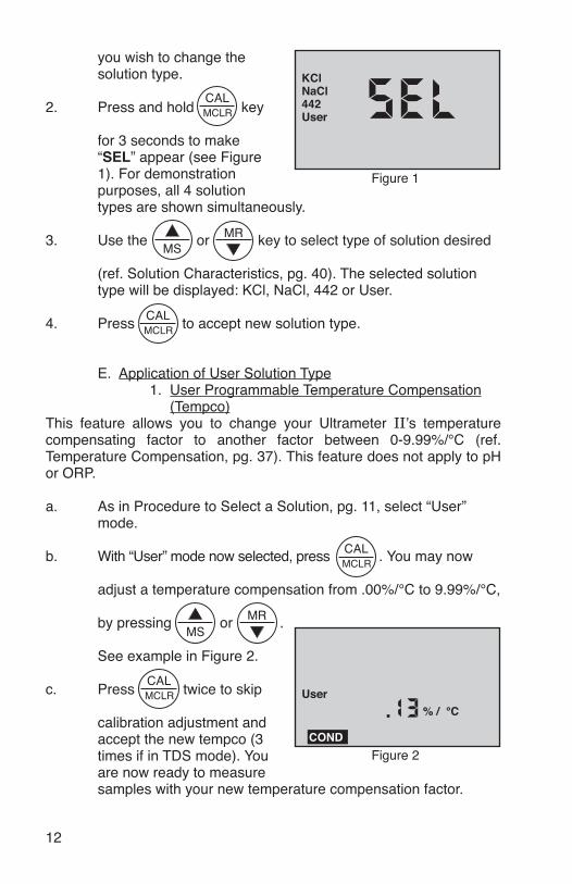
you wish to change the solution type.
2. Press and hold key
for 3 seconds to make “SEL” appear (see Figure 1). For demonstration purposes, all 4 solution types are shown simultaneously.
3. Use the or key to select type of solution desired
(ref. Solution Characteristics, pg. 40). The selected solution type will be displayed: KCl, NaCl, 442 or User.
4. Press to accept new solution type.
E. Application of User Solution Type 1. User Programmable Temperature Compensation (Tempco)This feature allows you to change your Ultrameter II’s temperature compensating factor to another factor between 0-9.99%/°C (ref. Temperature Compensation, pg. 37). This feature does not apply to pH or ORP.
a. As in Procedure to Select a Solution, pg. 11, select “User” mode.
b. With “User” mode now selected, press . You may now
adjust a temperature compensation from .00%/°C to 9.99%/°C,
by pressing or .
See example in Figure 2.
c. Press twice to skip
calibration adjustment and accept the new tempco (3 times if in TDS mode). You are now ready to measure samples with your new temperature compensation factor.
Figure 1
KCl
442NaCl
User
Figure 2
°C% /User
COND

13
2. Disabling Temperature Compensationa. Select “User” mode (ref. Procedure to Select a Solution, pg. 11).
b. With “User” selected, press . If the display does not
show .00%/°C, hold long enough to bring the tempco to
.00%/°C (see Figure 3).
c. Press twice
(3 times if in TDS mode). Temperature compensation is now disabled (=0) for measurements in “User” mode.
3. User Programmable Conductivity to TDS RatioThis feature allows you to select a custom conductivity to TDS conversion ratio within the range of 0.20-7.99 for “User” mode measurements.To determine the conversion ratio for a custom solution of known TDS ppm value, measure the solution conductivity at 25ºC with the Ultrameter II and divide the ppm value by the µS value. For example, a solution of known 75 ppm TDS and measured 100 µS conductivity at 25ºC would have a conversion ratio of 75/100 or 0.75. Enter the new conversion ratio as follows:
a. While in “User” mode, press .
b. Press twice (to skip over tempco adjustment) and
“RATIO” will appear (see Figure 4).
c. Adjust with or
key until new conversion ratio is displayed.
d. Press twice (to skip over calibration adjustment) to accept new conversion ratio. You are now ready to measure samples with the new conductivity/TDS ratio.
Figure 3
°C% /User
COND
Figure 4
RATIOUser
TDS
In these first six sections, you have learned all you need to make accurate measurements.The following sections contain calibration,advanced operations and technical information.

14
VII. CALIBRATION A. Calibration IntervalsGenerally, calibration is recommended about once per month with Conductivity or TDS solutions. Calibration with pH solutions should be checked twice a month. Calibration of ORP is not necessary (ref. CALIBRATION INTERVALS, pg. 19).
B. Rules for Calibration of the Ultrameter II 1. Calibration Steps a. Starting Calibration
Calibration is begun by pressing while measuring Conductivity,
TDS or pH. Measuring continues, but the “CAL” icon is on, indicating calibration is now changeable.
The reading is changed with the and keys to match the
known value. The calibration for each of the 4 solution types may be performed in either conductivity or TDS mode.
Depending on what is being calibrated, there may be 1, 2 or 3 steps to the calibration procedures.
Once in “CAL” mode, the key becomes an “ACCEPT” key. At
each point, pressing accepts the new calibration value and steps
you to the next adjustment (or out of “CAL” mode if there are no more steps).
To bypass a calibration step, simply press to accept the present value as is.
b. Leaving CalibrationCalibration is complete when the “CAL” icon goes out. Pressing any
KCl, NaCl or 442 UserCond Gain only Tempco, then GainRes Done in conductivity Done in conductivity or TDSTDS Gain only Tempco, Ratio, then GainpH 7, acid and/or base (6Psi)ORP Zero set with pH 7 automatically (6Psi)

15
measurement key cancels changes not yet accepted and exits calibration mode.Leaving pH after the 2nd buffer results in the same gain being entered in place of the 3rd buffer.
2. Calibration LimitsThere are calibration limits. A nominal “FAC” value is an ideal value stored by the factory. Attempts to calibrate too far, up or down, from there will cause the displayed value to be replaced with “FAC”. If you accept it (press the “Cal” key), you will have the original default factory calibration for this measurement. The need to calibrate so far out that “FAC” appears indicates a procedural problem, incorrect standard solution, a very dirty cell cup or an aging pH/ORP sensor (ref. Troubleshooting Chart, pg. 34).
C. Calibration Procedures 1. Conductivity or TDS Calibration
a. Rinse conductivity cell three times with proper standard (KCl, NaCl, or 442) (ref. Cond/TDS Standard Solutions, pg. 36). For user calibration see User Calibration Conductivity/TDS below.
b. Refill conductivity cell with same standard. KCl-7000 shown.
c. Press or , then
press ; “CAL” icon will
appear on the display (see Figure 5).
d. Press or to
step the displayed value toward the standard’s value (7032 > 7000) or hold a key down to scroll rapidly through the reading.
e. Press once to confirm new value and end the
calibration sequence for this particular solution type. If another solution type is also to be measured, change solution type now and repeat this procedure.
2. User Calibration Conductivity/TDSInstrument must be in “User” mode, see Solution Selection, pg. 11.
Figure 5
°C
KCl
COND
CAL

16
a. Rinse conductivity cell three times with your standard.
b. Refill conductivity cell with same standard.
c. Press or , then press twice in COND/three
times in TDS. The “CAL” icon will appear on the display.
d. Press or to step the displayed value toward the
standard’s value or hold a key down to scroll rapidly through the reading.
e. Press once to confirm new value and end the
calibration sequence for this particular solution type.
3. Resistivity CalibrationResistivity is the reciprocal of Conductivity. To calibrate resistivity, calibrate conductivity for the solution type you wish to measure (ref. Conductivity or TDS Calibration, pg. 15).
4. Reloading Factory Calibration (Cond or TDS)If calibration is suspect or known to be incorrect, and no standard solution is available, the calibration value can be replaced with the original factory value for that solution. This “FAC” value is the same for all Ultrameter IIs, and returns you to a known state without solution in the cell. The “FAC” internal electronics calibration (which bypasses the electrodes and cell) is not intended to replace calibration with conductivity/TDS standard solutions. If another solution type requires resetting, change solution type and repeat this procedure.
a. Press or .
b. Press . (If in “User” solution mode, press CAL key
twice if in Conductivity, and three times if in TDS to skip over tempco and ratio adjustments.)
c. Press key until “FAC” appears and release.
d. Press to accept the factory calibration setting.

17
5. pH Calibration (6Psi)
Important: Always “zero” your Ultrameter II with a pH 7 buffer solution before adjusting the gain with acid or base buffers, i.e., 4 and/or 10, etc.
a. pH Zero Calibration (6Psi)
1. Rinse sensor well and cell cup 3 times with 7 buffer solution.
2. Refill both sensor well and cell cup with 7 buffer solution.
3. Press to verify the pH calibration. If the display shows 7.00, skip the pH Zero Calibration and proceed to section b. pH Gain Calibration.
4. Press to enter calibration mode. The “CAL”, “BUFFER” and “7” annunciators will appear (see Figure 6). Displayed value will be the uncalibrated sensor.
NOTES: If a wrong buffer is added (outside of 6-8 pH),“7” and “BUFFER” will flash, and the Ultrameter II will not adjust.The uncalibrated pH value displayed in step 4 will assist in determining the accuracy of the pH sensor. If the pH reading is above 8 with pH 7 buffer solution, the sensor well needs additional rinsing or the pH sensor is defective and needs to be replaced.
5. Press or until the display reads 7.00.
NOTE: Attempted calibration of >1 pH point from factory calibration will cause “FAC” to appear. This indicates the need for sensor replacement (ref. Troubleshooting pg. 34) or fresh buffer solution. The “FAC” internal electronic calibration is not intended to replace calibration with pH buffers. It assumes an ideal pH sensor. Each “FAC” indicates a factory setting for that calibration step (i.e., 7, acid, base).
You may press to accept the preset factory value, or you may
Figure 6
BUFFER
pH
CAL

18
reduce your variation from factory setting by pressing or .
6. Press to accept the new value. The pH Zero Calibration
is now complete. You may continue with pH gain Calibration or exit by pressing any measurement key.
b. pH gain Calibration (6Psi)
Important: Always calibrate or verify your Ultrameter II with a pH 7 buffer solution before adjusting the gain with acid or base buffers, i.e., 4 and/or 10, etc. Either acid or base solution can be used for the 2nd point “gain” calibration and then the opposite for the 3rd point. The display will verify that a buffer is in the sensor well by displaying either “Acd” or “bAS”.
1. The pH calibration mode is initiated by either completion of the pH Zero Calibration, or verifying 7 buffer and pressing the key twice while in pH measurement mode.
2. At this point the “CAL”, “BUFFER” and “Acd” or “bAS” annunciators will be displayed (see Figures 7 and 8).
NOTE: If the “Acd” and “bAS” indicators are blinking, the unit is indicating an error and needs either an acid or base solution present in the sensor well.
3. Rinse sensor well 3 times with acid or base buffer solution.
4. Refill sensor well again with same buffer solution.
5. Press or until display agrees with buffer value.
Figure 7
BUFFER
pH
CAL
Figure 8pH
BUFFER
CAL

19
6. Press to accept 2nd point of calibration. Now the
display indicates the next type of buffer to be used.
Single point gain Calibration is complete. You may continue for the 3rd point of Calibration (2nd gain) or exit by pressing any measurement key. Exiting causes the value accepted for the buffer to be used for both acid and base measurements. To continue with 3rd point calibration, use basic buffer if acidic buffer was used in the 2nd point, or vice-versa. Again, match the display to the known buffer value as in step 2 and continue with the following steps:
7. Repeat steps 3 through 6 using opposite buffer solution.
8. Press to accept 3rd point of calibration, which
completes the Calibration procedure. Fill sensor well with Myron L Storage Solution and replace protective cap.
6. ORP Calibration (6Psi)ORP electrodes rarely give false readings without problems in the reference electrode. For this reason, and because calibration solutions for ORP are highly reactive and potentially hazardous, your Ultrameter II has an electronic ORP calibration. This causes the zero point on the reference electrode to be set whenever pH 7 calibration is done.
7. Temperature CalibrationTemperature calibration is not necessary in the Ultrameter II.
VIII. CALIBRATION INTERVALS
There is no simple answer as to how often one should calibrate an instrument. The Ultrameter II is designed to not require frequent recalibration. The most common sources of error were eliminated in the design, and there are no mechanical adjustments. Still, to ensure specified accuracy, any instrument must be checked against chemical standards occasionally.
A. Suggested IntervalsOn the average, we expect calibration need only be checked monthly for the Conductivity, RES or TDS functions. The pH (6Psi) function should be checked every 2 weeks to ensure accuracy. Measuring some solutions will require more frequent intervals.

20
B. Calibration Tracking RecordsTo minimize your calibration effort, keep records. If adjustments you are making are minimal for your application, you can check less often. Changes in conductivity calibration should be recorded in percent. Changes in pH calibration (6Psi) are best recorded in pH units.
Calibration is purposely limited in the Ultrameter II to ±10% for the conductivity cell, as any change beyond that indicates damage, not drift. Likewise, calibration changes are limited to ±1 pH unit (6Psi), as any change beyond that indicates the end of the sensor’s lifetime and replacement is recommended.
C. Conductivity, RES, TDS Practices to Maintain Calibration
1. Clean oily films or organic material from the cell electrodes with foaming cleaner or mild acid. Do not scrub inside the cell.
2. Calibrate with solutions close to the measurements you make. Readings are compensated for temperature based on the type of solution. If you choose to measure tap water with a KCl compensation, which is often done (ref. An Example of 2 different solution selections and the resulting compensation, pg. 38), and you calibrate with 442 solution because it is handy, the further away from 25°C you are, the more error you have. Your records of calibration changes will reflect temperature changes more than the instrument’s accuracy.
3. Rinse out the cell with pure water after taking measurements. Allowing slow dissolving crystals to form in the cell contaminates future samples.
4. For maximum accuracy, keep the pH sensor cap on tight so that no fluid washes into the conductivity cell.
D. pH and ORP Practices to Maintain Calibration (6Psi)
1. Keep the sensor wet with Myron L Storage Solution.
2. Rinse away caustic solutions immediately after use.
ORP calibration solutions are caustic, and ±5% is considered very accurate. By using the pH zero setting (0 mV = 7 pH) for ORP and precision electronics for detection, the Ultrameter II delivers better accuracy without calibration than a simpler instrument could using calibration solutions.

21
IX. MEMORy
This feature allows up to 100 readings with their temperatures to be stored simultaneously for later recall. At the same time, the TIME and DATE are also recorded. To download the memory to a computer, (ref. bluDock™ WIRELESS DATA TRANSFER INSTRUCTIONS, pg. 30).
A. Memory Storage1. While displaying a measurement, press to record the displayed value.
2. “MEMORy” will appear and the temperature display will be momentarily replaced by a number (1-100) showing the position of the record. Figure 9 shows a reading of 1806 µS stored in memory record #4.
B. Memory Recall 1. Press any measurement key.
2. Press , “MEMORy” will appear, and the display will
show the last record stored.
3. Press or to scroll to the record location desired
(the temperature display alternates between temperature recorded and location number).
4. Press to display time and date stamp.
5. Press any measurement key to leave memory recall or allow to automatically turn off.
C. Clearing a Record/Memory ClearAfter recalling a certain record location, press and HOLD to
clear that memory. This space will be the place for the next memory record, unless you scroll to another empty position before ending the recall sequence. The next memory stored will go into the next highest available memory location.Example: You have locations 1-7 filled and wish to clear the conductivity reading stored in record location #3 and replace it with a pH reading.
Figure 9
°C
KCl
COND
MEMORY
22
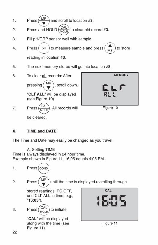
1. Press and scroll to location #3.
2. Press and HOLD to clear old record #3.
3. Fill pH/ORP sensor well with sample.
4. Press to measure sample and press to store
reading in location #3.
5. The next memory stored will go into location #8.
6. To clear all records: After
pressing , scroll down.
“CLr ALL” will be displayed (see Figure 10).
7. Press . All records will
be cleared.
X. TIME and DATE
The Time and Date may easily be changed as you travel.
A. Setting TIME Time is always displayed in 24 hour time. Example shown in Figure 11, 16:05 equals 4:05 PM.
1. Press .
2. Press until the time is displayed (scrolling through
stored readings, PC OFF, and CLr ALL to time, e.g., “16:05”).
3. Press to initiate.
“CAL” will be displayed along with the time (see Figure 11).
Figure 10
MEMORY
Figure 11
CAL

23
4. Press the or to change the time.
5. Press to accept the change (new time).
B. Setting DATE Example shown in Figure 12 is in US format, i.e., mo/dy/yr. NOTE: The default format is US. Date format may be changed (ref. Date Format “US and International (Int)”, pg. 24).
1. Press .
2. Press repeatedly until the date is displayed (scrolling
through stored readings, PC OFF, CLr ALL and time to the date, e.g., 03.05 10 (Figure 12), March 5, 2010).
3. Press to initiate. “CAL” will be displayed along with the
YEAR (see Figure 13).
4. Press or to
change the YEAR.
5. Press to accept the change (new year).
6. Press or to
change the month.
7. Press to accept the
change (new month), (see Figure 14).
Figure 12
Figure 13
CAL
Figure 14
CAL

24
8. Press the or
to change the day.
9. Press to accept
the change (new day) (see Figure 15).
C. DATE FORMAT “US & International (Int)”
1. Press .
2. Press repeatedly until the format is displayed (scrolling
through stored readings, PC OFF, CLr ALL, time and date to date format).
3. Press to change. Display will now indicate other format
(see Figures 16 & 17).
4. Press any measurement key or allow to automatically turn off.
XI. TEMPERATURE FORMAT “Centigrade & Fahrenheit”
1. Press .
2. Press to display the stored memory records.
3. Press repeatedly until you pass the “US” or “Int” date
Figure 15
CAL
Figure 16 Figure 17

25
format location. The display will show a “C” or “F” (see Figures 18 and 19).
4. Press to switch units.
5. Press to accept unit preference for all temperature
readings.
NOTE: Tempco will still be shown in %/°C.
XII. TOTAL RETURN to FACTORy SETTINGS “FAC SEL”
There may come a time when it would be desirable to quickly reset all the recorded calibration values in the instrument back to the factory settings. This might be to ensure all calibrations are set to a known value, or to give the instrument to someone else free of adjustments or recorded data for a particular application. NOTE: All stored data will be lost.
1. Press .
2. Press to display the stored memory records.
3. Press repeatedly
until you pass the CLr ALL and the C-F locations. The display will show a “FAC SEL” (see Figure 20).
4. Press to accept the resetting. Display will return to
Conductivity.
Figure 18 Figure 19
Figure 20

26
XIII. CELL ChECK
The cell check verifies the cleanliness of the conductivity/TDS/resistivity sensor. In normal use the cell may become dirty or coated and require cleaning. If the display is showing “.00” when the cell cup is dry, the sensor is probably clean. However, when testing high purity water in resistivity (“RES”) mode improved accuracy may be desired. No matter what a manufacturer claims, a sensor can and will become contaminated or coated and, therefore, require cleaning. A true 4-wire sensor, as in the Ultrameter II, helps to mitigate contamination, but NO SENSOR IS 100% IMMUNE.
1. Press .
2. Press to display the
stored memory records.
3. Press repeatedly until
you pass the FAC SEL location. The display will show a “CELL ch” (see Figure 21).
4. Press to test.
If cell is clean, “Good” will momentarily be displayed (see Figure 22). If cell is dirty, “CELL cLn” will be displayed (see Figure 23) (ref. Cleaning Sensors, pg. 32).
XIV. AUTO OFF
Auto off allows the user to adjust the time the instrument is ON (up to 75 seconds) after each press of a key. Default time is 15 seconds with 60 seconds in “CAL” (calibration) mode.
1. Press .
Figure 21
Figure 22
Figure 23
Figure 24
27
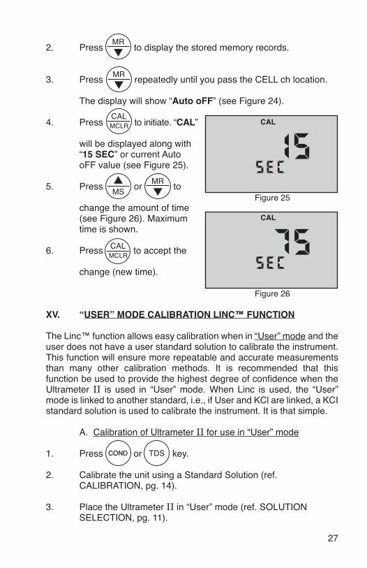
2. Press to display the stored memory records.
3. Press repeatedly until you pass the CELL ch location.
The display will show “Auto oFF” (see Figure 24).
4. Press to initiate. “CAL”
will be displayed along with “15 SEC” or current Auto oFF value (see Figure 25).
5. Press or to
change the amount of time (see Figure 26). Maximum time is shown.
6. Press to accept the
change (new time).
XV. “USER” MODE CALIBRATION LINC™ FUNCTION
The Linc™ function allows easy calibration when in “User” mode and the user does not have a user standard solution to calibrate the instrument. This function will ensure more repeatable and accurate measurements than many other calibration methods. It is recommended that this function be used to provide the highest degree of confidence when the Ultrameter II is used in “User” mode. When Linc is used, the “User” mode is linked to another standard, i.e., if User and KCl are linked, a KCI standard solution is used to calibrate the instrument. It is that simple.
A. Calibration of Ultrameter II for use in “User” mode
1. Press or key.
2. Calibrate the unit using a Standard Solution (ref. CALIBRATION, pg. 14).
3. Place the Ultrameter II in “User” mode (ref. SOLUTION SELECTION, pg. 11).
Figure 25
CAL
Figure 26
CAL

28
4. Verify/Set the calibration linc. (See below – Setting “User” Mode Calibration “Linc”.)
B. Setting “User” mode Calibration “Linc”The Linc function sets or “links” the calibration gain factor of a Standard Solution to the User solution mode. Once set, the “Linc” will stay intact with future calibrations unless the Linc has been canceled. For more information on canceling the “User” mode Calibration Linc refer to the section “Canceling “User” mode Calibration “Linc””, pg. 29. Follow the steps below to set either the KCl, NaCl or 442 calibration factor to the User solution mode.
1. Press measurement key desired to be “Linked”, i.e., , or .
2. Place the Ultrameter II in “User” mode (ref. SOLUTION SELECTION, pg. 11, for selecting the “User” mode).
3. Press arrow key until
the menu “Linc” appears (see Figure 27).
4. Press key. The
instrument will display “SEL” and the “User” Icon (see Figure 28).
Any additional display of KCl, NaCl or 442 icons indicates a “Linc”between the User solution and the other solution displayed.
5. Press or keys
to select a Standard Solution to be linked to the “User” mode calibration constant (see Figure 29). “User” is linked to “KCl”. If none of the Solution Selection icons are displayed (i.e., KCl, NaCl or 442), nothing has been linked to “User” mode.
Figure 27
Figure 28
User
Figure 29
KCl
User
29
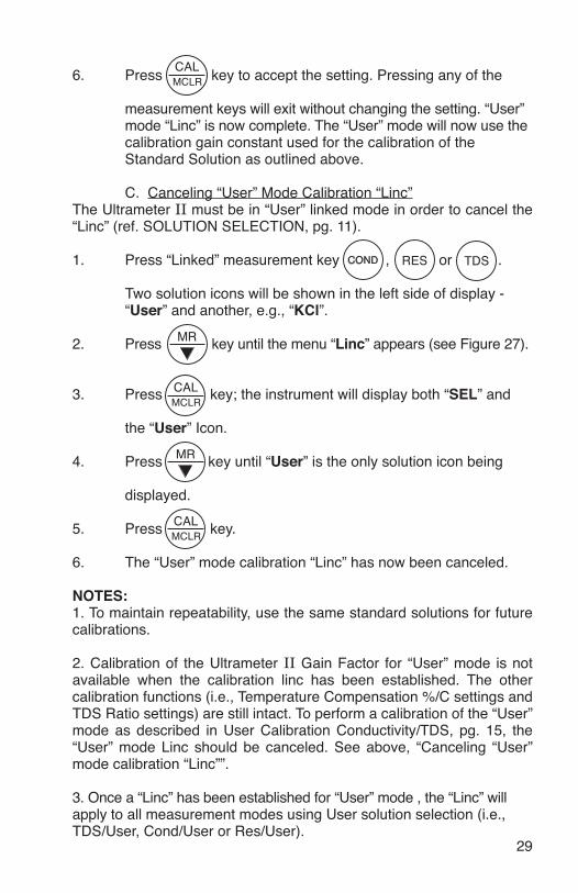
6. Press key to accept the setting. Pressing any of the
measurement keys will exit without changing the setting. “User” mode “Linc” is now complete. The “User” mode will now use the calibration gain constant used for the calibration of the Standard Solution as outlined above.
C. Canceling “User” Mode Calibration “Linc”The Ultrameter II must be in “User” linked mode in order to cancel the “Linc” (ref. SOLUTION SELECTION, pg. 11).
1. Press “Linked” measurement key , or .
Two solution icons will be shown in the left side of display - “User” and another, e.g., “KCl”.
2. Press key until the menu “Linc” appears (see Figure 27).
3. Press key; the instrument will display both “SEL” and
the “User” Icon.
4. Press key until “User” is the only solution icon being
displayed.
5. Press key.
6. The “User” mode calibration “Linc” has now been canceled.
NOTES:1. To maintain repeatability, use the same standard solutions for future calibrations.
2. Calibration of the Ultrameter II Gain Factor for “User” mode is not available when the calibration linc has been established. The other calibration functions (i.e., Temperature Compensation %/C settings and TDS Ratio settings) are still intact. To perform a calibration of the “User” mode as described in User Calibration Conductivity/TDS, pg. 15, the “User” mode Linc should be canceled. See above, “Canceling “User” mode calibration “Linc””.
3. Once a “Linc” has been established for “User” mode , the “Linc” will apply to all measurement modes using User solution selection (i.e., TDS/User, Cond/User or Res/User).

30
XVI. bluDock™ WIRELESS DATA TRANSFER INSTRUCTIONS
NOTE: Bluetooth® is a registered trademark of Bluetooth SIG. The bluDock Bluetooth module is a registered Bluetooth device.
Requires Myron L bluDock™ accessory package, Model # BLUDOCK. Package includes Ultrameter II hardware modification that allows the unit to communicate wirelessly with a personal computer configured for wireless device communication. Package also includes U2CI software application that will operate on Windows XP, Vista and 7*, and Macintosh OSX** based computer systems and Bluetooth USB adapter (dongle) for computers that do not have Bluetooth capability.
A. Software Installation1. Place Myron L Ultrameter II U2CI Installation CD v2.0.0 & later into your computer or download U2CI application from the Myron L website: http://myronl.com/main/U2CI_Application_DL.htm2. Upon opening, select the folder for your operating system. 3. Install U2CI application. See detailed installation instructions on CD or Myron L website: http://myronl.com/main/U2CI_Application_DL.htm4. Additional drivers may be required. See our website for the latest information.
B. Hardware SetupFor a computer without Bluetooth® capability:If you don’t have the dongle that came with the BLUDOCK, one can be ordered separately from the Myron L Company. Order Model # BDDO.Plug in your dongle and install per manufacturer’s instructions.
For computers with Bluetooth capability/Bluetooth dongle installed: First time use of the bluDock:1. Press any parameter button to turn the Ultrameter II on.2. Put the Ultrameter II in “PC On” mode by pressing the
key until “PC OFF”
appears (see Figure 30).
3. Then press the key.
“PC On” will be displayed (see Figure 31).
Figure 30
Figure 31

31
NOTE: “PC Ini” may momentarily be displayed while initializing (see Figure 32). 4. Add bluDock to your Bluetooth devices per your operating system procedure. ThE BLUDOCK DEVICE PASSKEy IS 1234.5. After pairing, note the number of the COM port assigned by the computer. In Windows XP, note the number of the outgoing COM port assigned by the computer.
NOTE: The unit will automatically power down after 60 sec. If the unit powers down during pairing, repeat steps 1-3 above and continue.
C. Memory Stack Download1. With the Ultrameter II in “PC On” mode, open the U2CI software application.2. Verify that the port selected matches the COM port number noted (first time only). This is the outgoing COM port on Windows XP.3. In the U2CI application, click on the data download button. A data transfer bar will appear while the data is being downloaded.
Once downloaded, the data may be manipulated, printed or stored within the Myron L U2CI application, or the data may be exported to another more powerful spreadsheet†, such as Excel*.
† Please Note: Although the Myron L Company has performed extensive testing, we cannot guarantee compatibility of all applications and formats. We suggest testing your application and format for compatibility before relying on it.
Additional features such as assigning a name to the unit, setting time and date and erasing data are available. See U2CI software installation CD or visit our website for the latest instructions:http://myronl.com/main/U2CI_Application_DL.htm
4. Upon completion, click on the “disconnect” icon.5. Turn off Ultrameter II PC download mode by selecting any measurement function. Failure to do so will reduce battery life.
* Windows 2000, 2007, XP & Vista are registered trademarks of Microsoft Corporation.** Macintosh OS9.2 & OSX are registered trademarks of Apple Computer Inc.
Figure 32

32
XVII. CARE and MAINTENANCE
Ultrameter IIs should be rinsed with clean water after use. Solvents should be avoided. Shock damage from a fall may cause instrument failure.
A. Temperature ExtremesSolutions in excess of 71°C/160°F should not be placed in the cell cup area; this may cause damage. The pH sensor may fracture if the Ultrameter II temperature is allowed to go below 0°C/32°F. Care should be exercised not to exceed rated operating temperature.
Leaving the Ultrameter II in a vehicle or storage shed on a hot day can easily subject the instrument to over 66°C/150°F. This will void the warranty.
B. Battery ReplacementDry Instrument ThOROUGhLy. Remove the four (4) bottom screws. Open instrument carefully. Carefully detach battery from circuit board. Replace with 9 volt alkaline battery. Replace bottom, ensuring the sealing gasket is installed in the groove of the top half of case. Re-install screws, tighten evenly and securely.
NOTE: Because of nonvolatile EEPROM circuitry, all data stored in memory and all calibration settings are protected even during power loss or battery replacement. However, loss of time and date may occur if battery is removed for longer than 3 minutes (180 seconds).
C. pH/ORP Sensor Replacement (6Psi)Order model RPR. When ordering, be sure to include the model and serial number of your instrument to ensure receipt of the proper type. Complete installation instructions are provided with each replacement sensor.
D. Cleaning Sensors 1. Conductivity/TDS/ResistivityThe conductivity cell cup should be kept as clean as possible. Flushing with clean water following use will prevent buildup on electrodes. However, if very dirty samples — particularly scaling types — are allowed to dry in the cell cup, a film will form. This film reduces accuracy. When there are visible films of oil, dirt, or scale in the cell cup or on the electrodes, use isopropyl alcohol or a foaming non-abrasive household cleaner. Rinse out the cleaner and your Ultrameter II is again ready for accurate measurements.
2. pH/ORP (6Psi)The unique pH/ORP sensor in your Ultrameter II is a nonrefillable combination type that features a porous liquid junction. It should not be

33
allowed to dry out. However, if this occurs, the sensor may sometimes be rejuvenated by first cleaning the sensor well with Isopropyl alcohol or a liquid spray cleaner such as Windex™ or Fantastic™ and rinsing well. Do not scrub or wipe the pH/ORP sensor.
Then use one of the following methods: 1. Pour a HOT salt solution ~60°C/140°F — a potassium chloride (KCI) solution such as Myron L pH/ORP Sensor Storage Solution is preferable, but HOT tap water with table salt (NaCl) will work fine — in the sensor well and allow to cool. Retest. or2. Pour DI water in the sensor well and allow to stand for no more than 4 hours (longer can deplete the reference solution and damage the glass bulb). Retest. If neither method is successful, the sensor must be replaced.
“Drifting” can be caused by a film on the pH sensor bulb and/or reference. Use isopropyl alcohol (IPA) or spray a liquid cleaner such as Windex™ or Fantastic™ into the sensor well to clean it. The sensor bulb is very thin and delicate. Do not scrub or wipe the pH/ORP sensor.
Leaving high pH (alkaline) solutions in contact with the pH sensor for long periods of time is harmful and will cause damage. Rinsing such liquids from the pH/ORP sensor well and refilling it with Myron L Storage Solution, a saturated KCl solution, pH 4 buffer, or a saturated solution of table salt and tap water, will extend the useful life.
Samples containing chlorine, sulfur, or ammonia can “poison” any pH electrode. If it is necessary to measure the pH of any such sample, thoroughly rinse the sensor well with clean water immediately after taking the measurement. Any sample element that reduces (adds an electron to) silver, such as cyanide, will attack the reference electrode.
Replacement sensors are available only from the Myron L Company or its authorized distributors (see Replacement pH/ORP Sensor (6Psi), pg. 37).
pH/ORP SENSOR Top View
ORP Electrode
pH Glass Electrode
SensorBody
Reference Junction under Glass pH Bulb

34
XVIII. TROUBLEShOOTING ChART
Symptom Possible CauseNo display, even though measurement key pressed
Battery weak or not connected.
Inaccurate ph readings (6Psi)
1. pH calibration needed. Ref. pH Cal., pg. 17.2. Cross-contamination from residual pH buffers or samples in sensor well.3. Calibration with expired pH buffers.
No response to ph changes(6Psi)
Sensor bulb is cracked or an electromechanical short caused by an internal crack.
Will not adjust down to ph 7(6Psi)
pH/ORP sensor has lost KCl.
ph readings drift or respond slowly to changes in buffers/samples
or
“FAC” is displayed repeatedly (6Psi)
1. Temporary condition due to “memory” of solution in pH sensor well for long periods.2. Bulb dirty or dried out. 3. Reference junction clogged or coated.
Unstable Conductivity/TDS/Resistivity readings
1. Dirty electrodes. 2. Test samples greater than 1 megohm.
Unable to calibrate Conductivity/TDS
Film or deposits on electrodes.
Resistivity readings much lower than expected
1. Contamination from previous sample or from pH sensor well.2. Carbon dioxide in test sample.
Corrective ActionCheck connections or replace battery. Ref. Battery Replacement, pg. 32.1. Recalibrate instrument.2. Thoroughly rinse sensor well.3. Recalibrate using fresh buffers. Ref. pH Buffer Solutions, pg. 36.
Replace pH/ORP sensor. Ref. Replacement pH/ORP Sensor, pg. 37.
Clean and rejuvenate sensor (ref. Cleaning Sensors, pg. 32) and recalibrate. If no improvement, replace pH/ORP sensor (ref. Replacement pH/ORP Sensor, pg. 37). Clean and rejuvenate sensor (ref. Cleaning Sensors, pg. 32) and recalibrate. If no improvement, replace pH/ORP sensor (ref. Replacement pH/ORP Sensor, pg. 37).
1. Clean cell cup and electrodes. Ref. Cleaning Sensors, pg. 32.2. Minimize test sample exposure to air. Ref. Measuring Resistivity, pg. 10.Clean cell cup and electrodes. Ref. Cleaning Sensors, pg. 32.1. Rinse cell cup more thoroughly before measurement. Ensure pH cap is snugly in place.2. See Measuring Resistivity, pg. 10.

35
Symptom Possible CauseNo display, even though measurement key pressed
Battery weak or not connected.
Inaccurate ph readings (6Psi)
1. pH calibration needed. Ref. pH Cal., pg. 17.2. Cross-contamination from residual pH buffers or samples in sensor well.3. Calibration with expired pH buffers.
No response to ph changes(6Psi)
Sensor bulb is cracked or an electromechanical short caused by an internal crack.
Will not adjust down to ph 7(6Psi)
pH/ORP sensor has lost KCl.
ph readings drift or respond slowly to changes in buffers/samples
or
“FAC” is displayed repeatedly (6Psi)
1. Temporary condition due to “memory” of solution in pH sensor well for long periods.2. Bulb dirty or dried out. 3. Reference junction clogged or coated.
Unstable Conductivity/TDS/Resistivity readings
1. Dirty electrodes. 2. Test samples greater than 1 megohm.
Unable to calibrate Conductivity/TDS
Film or deposits on electrodes.
Resistivity readings much lower than expected
1. Contamination from previous sample or from pH sensor well.2. Carbon dioxide in test sample.
Corrective ActionCheck connections or replace battery. Ref. Battery Replacement, pg. 32.1. Recalibrate instrument.2. Thoroughly rinse sensor well.3. Recalibrate using fresh buffers. Ref. pH Buffer Solutions, pg. 36.
Replace pH/ORP sensor. Ref. Replacement pH/ORP Sensor, pg. 37.
Clean and rejuvenate sensor (ref. Cleaning Sensors, pg. 32) and recalibrate. If no improvement, replace pH/ORP sensor (ref. Replacement pH/ORP Sensor, pg. 37). Clean and rejuvenate sensor (ref. Cleaning Sensors, pg. 32) and recalibrate. If no improvement, replace pH/ORP sensor (ref. Replacement pH/ORP Sensor, pg. 37).
1. Clean cell cup and electrodes. Ref. Cleaning Sensors, pg. 32.2. Minimize test sample exposure to air. Ref. Measuring Resistivity, pg. 10.Clean cell cup and electrodes. Ref. Cleaning Sensors, pg. 32.1. Rinse cell cup more thoroughly before measurement. Ensure pH cap is snugly in place.2. See Measuring Resistivity, pg. 10.

36
XIX. ACCESSORIES
A. Conductivity/TDS Standard SolutionsYour Ultrameter II has been factory calibrated with the appropriate Myron L Company NIST traceable KCl, NaCl, and our own 442™ standard solutions. Most Myron L conductivity standard solution bottles show three values referenced at 25°C: Conductivity in microsiemens/micromhos, the ppm/TDS equivalents (based on our 442 Natural Water™) and NaCl standards. All standards are within ±1.0% of reference solutions. Available in 2 oz., quarts/liters, and gallon/~3.8 liter bottles.
1. Potassium Chloride (KCl)The concentrations of these reference solutions are calculated from data in the International Critical Tables, Vol. 6. The 7000 µS is the recommended standard. Order KCL-7000
2. 442 Natural Water™442 Natural Water Standard Solutions are based on the following salt proportions: 40% sodium sulfate, 40% sodium bicarbonate, and 20% sodium chloride, which represent the three predominant components (anions) in freshwater. This salt ratio has conductivity characteristics approximating fresh natural waters and was developed by the Myron L Company over four decades ago. It is used around the world for measuring both conductivity and TDS in drinking water, ground water, lakes, streams, etc. 3000 ppm is the recommended standard. Order 442-3000
3. Sodium Chloride (NaCl)This is especially useful in sea water mix applications, as sodium chloride is the major salt component. Most Myron L standard solution labels show the ppm NaCl equivalent to the conductivity and to ppm 442 values. The 14.0 mS is the recommended standard. Order NACL-14.0
B. pH Buffer Solutions (6Psi)pH buffers are available in pH values of 4, 7 and 10. Myron L Company buffer solutions are traceable to NIST certified pH references and are color-coded for instant identification. They are also mold inhibited and accurate to within ±0.01 pH units @ 25°C. Order 4, 7 or 10 Buffer.Available in 2 oz., quarts/liters, and gallon/~3.8 liter bottles.
C. pH Sensor Storage Solution (6Psi)Myron L pH Sensor Storage Solution prolongs the life of the pH sensor. Available in 2 oz., quarts/liters, and gallon/~3.8 liter bottles.
D. Soft Protective Carry CasesPadded Nylon carrying case features a belt clip for hands-free mobility.

37
Two colors to choose from; Blue - Model #: UCC Desert Tan - Model #: UCCDT
E. Hard Protective Carry CasesLarge case with 2 oz. bottles of calibration standard solutions (KCl-7000, 442-3000, 4, 7, & 10 pH buffers and pH storage solution). Model #: PKUUSmall case (no calibration standard solutions) - Model #: UPP
F. Replacement pH/ORP Sensor (6Psi) pH/ORP sensor is gel filled and features a unique porous liquid junction. It is user-replaceable and comes with easy to follow instructions. Model #: RPR
G. bluDock™ Wireless Data Transfer Accessory PackageThis accessory allows the operator to download the Ultrameter II memory stack to a spreadsheet on a computer. The package includes bluDock modified circuit board in the unit, software CD, installation and operating instructions, and dongle. Model #: BLUDOCK
XX. TEMPERATURE COMPENSATION (Tempco) of Aqueous Solutions
Electrical conductivity indicates solution concentration and ionization of the dissolved material. Since temperature greatly affects ionization, conductivity measurements are temperature dependent and are normally corrected to read what they would be at 25°C.
A. Standardized to 25°CConductivity is measured with great accuracy in the Ultrameter II using a method that ignores fill level, electrolysis, electrode characteristics, etc., and features a microprocessor to perform temperature compensation. In simpler instruments, conductivity values are usually assigned an average correction similar to that of KCl solutions for correction to 25°C. The correction to an equivalent KCl solution is a standard set by chemists that standardizes the measurements and allows calibration with precise KCl solutions. In the Ultrameter II, this correction can be set to other solutions or tailored for special measurements or applications.
B. Tempco VariationMost conductivity instruments use an approximation of the temperature characteristics of solutions, perhaps even assuming a constant value. The value for KCl is often quoted simply as 2%/°C. In fact, KCl tempco

38
varies with concentration and temperature in a non-linear fashion. Other solutions have more variation still. The Ultrameter II uses corrections that change with concentration and temperature instead of single average values. See Chart 1.
C. An Example of 2 different solution selections and the resulting compensation
How much error results from treating natural water as if it were KCl at 15°C?
A tap water solution should be compensated as 442 with a tempco of 1.68 %/°C, where the KCl value used would be 1.90 %/°C.
Suppose a measurement at 15°C/59°F is 900 microsiemens of true uncompensated conductivity.
Using a 442 correction of 10 (degrees below 25) x 1.68% indicates the solution is reading 16.8% low. For correction, dividing by (.832) yields 1082 microsiemens as a compensated reading.
A KCl correction of 10 (degrees below 25) x 1.9% indicates the solution is reading 19% low. Dividing by (.81) yields 1111 microsiemens for a compensated reading. The difference is 29 out of 1082 = 2.7%.
Chart 1 0 5 10 15 20 25 30 35 40 45 50 55 60
1.500%
1.600%
1.700%
1.800%
1.900%
2.000%
2.100%
2.200%
2.300%
2.400%
2.500%
KCl % / °C
% / °C
Temperature
39
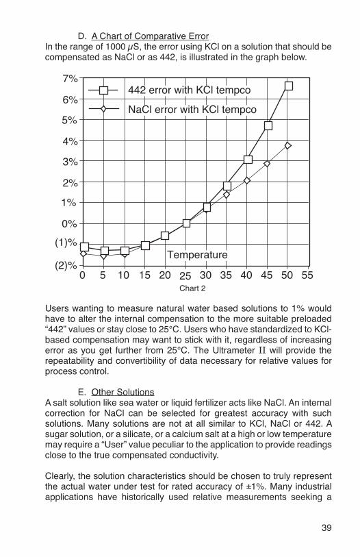
D. A Chart of Comparative ErrorIn the range of 1000 µS, the error using KCl on a solution that should be compensated as NaCl or as 442, is illustrated in the graph below.
Users wanting to measure natural water based solutions to 1% would have to alter the internal compensation to the more suitable preloaded “442” values or stay close to 25°C. Users who have standardized to KCl- based compensation may want to stick with it, regardless of increasing error as you get further from 25°C. The Ultrameter II will provide the repeatability and convertibility of data necessary for relative values for process control.
E. Other SolutionsA salt solution like sea water or liquid fertilizer acts like NaCl. An internal correction for NaCl can be selected for greatest accuracy with such solutions. Many solutions are not at all similar to KCl, NaCl or 442. A sugar solution, or a silicate, or a calcium salt at a high or low temperature may require a “User” value peculiar to the application to provide readings close to the true compensated conductivity.
Clearly, the solution characteristics should be chosen to truly represent the actual water under test for rated accuracy of ±1%. Many industrial applications have historically used relative measurements seeking a
7%
Chart 255
(1)%
(2)%
0%
1%
2%
3%
4%
5%
6%
0 5 10 15 20 25 30 35 40 45 50
Temperature
NaCl error with KCl tempco
442 error with KCl tempco

40
number to indicate a certain setpoint or minimum concentration or trend. The Ultrameter II gives the user the capability to collect data in “KCl conductivity units” to compare to older published data, in terms of NaCl or 442, or as appropriate. The Ultrameter II can be used to reconcile data taken with other compensation assumptions, especially with its ability to allow custom characteristics through the “User” mode.
XXI. CONDUCTIVITy CONVERSION to TOTAL DISSOLVED SOLIDS (TDS)
Electrical conductivity indicates solution concentration and ionization of the dissolved material. Since temperature greatly affects ionization, conductivity measurements are temperature dependent and are normally corrected to read what they would be at 25°C (ref. Temperature Compensation, pg. 37).
A. How it’s DoneOnce the effect of temperature is removed, the compensated conductivity is a function of the concentration (TDS). Temperature compensation of the conductivity of a solution is performed automatically by the internal processor with data derived from chemical tables. Any dissolved salt at a known temperature has a known ratio of conductivity to concentration. Tables of conversion ratios referenced to 25°C have been published by chemists for decades.
B. Solution CharacteristicsReal world applications have to measure a wide range of materials and mixtures of electrolyte solutions. To address this problem, industrial users commonly use the characteristics of a standard material as a model for their solution, such as KCl, which is favored by chemists for its stability.
Users dealing with sea water, etc., use NaCl as the model for their concentration calculations. Users dealing with freshwater work with mixtures including sulfates, carbonates and chlorides, the three predominant components (anions) in freshwater that the Myron L Company calls “natural water”. These are modeled in a mixture called “442™” which the Myron L Company markets for use as a calibration standard, as it does standard KCl and NaCl solutions.
The Ultrameter II contains algorithms for these 3 most commonly referenced compounds. The solution type in use is displayed on the left. Besides KCl, NaCl, and 442, there is the “User” choice. The benefit of “User” is that one may enter the temperature compensation and TDS ratio by hand, greatly increasing accuracy of

41
readings for a specific solution. That value remains a constant for all measurements and should be reset for different dilutions or temperatures.
C. When does it make a lot of difference?First, the accuracy of temperature compensation to 25°C determines the accuracy of any TDS conversion. Assume we have industrial process water to be pretreated by RO. Assume it is 45°C and reads 1500 µS uncompensated.
1. If NaCl compensation is used, an instrument would report 1035 µS compensated, which corresponds to 510 ppm NaCl. 2. If 442 compensation is used, an instrument would report 1024 µS compensated, which corresponds to 713 ppm 442.
The difference in values is 40%.
In spite of such large error, some users will continue to take data in the “NaCl” mode because their previous data gathering and process monitoring was done with an older NaCl referenced device.
Selecting the correct Solution Type on the Ultrameter II will allow the user to attain true TDS readings that correspond to evaporated weight. If none of the 3 standard solutions apply, the “User” mode must be used. Temperature Compensation (Tempco) and TDS Derivation below, details the “User” mode.
XXII. TEMPERATURE COMPENSATION (Tempco) and TDS DERIVATION
The Ultrameter II contains internal algorithms for characteristics of the 3 most commonly referenced compounds. The solution type in use is displayed on the left. Besides KCl, NaCl, and 442, there is the “User” choice. The benefit of “User” mode is that one may enter the tempco and TDS conversion values of a unique solution via the keypad. A. Conductivity CharacteristicsWhen taking conductivity measurements, the Solution Selection determines the characteristic assumed as the instrument reports what a measured conductivity would be if it were at 25°C. The characteristic is represented by the tempco, expressed in %/°C. If a solution of 100 µS at 25°C increases to 122 µS at 35°C, then a 22% increase has occurred

42
over this change of 10°C. The solution is then said to have a tempco of 2.2 %/°C.
Tempco always varies among solutions because it is dependent on their individual ionization activity, temperature and concentration. This is why the Ultrameter II features mathematically generated models for known salt characteristics that also vary with concentration and temperature.
B. Finding the Tempco of an Unknown SolutionOne may need to measure compensated conductivity of some solution unlike any of the 3 standard salts. In order to enter a custom fixed tempco for a limited measurement range, enter a specific value through the “User” function. The tempco can be determined by 2 different methods:
1. Heat or cool a sample of the solution to 25°C, and measure itsconductivity. Heat or cool the solution to a typical temperature where it is normally measured. After selecting “User” function, set the tempco to 0 %/°C as in Disabling Temperature Compensation, pg. 13 (No compensation). Measure the new conductivity and the new temperature. Divide the % decrease or increase by the 25°C value. Divide that difference by the temperature difference.
2. Heat or cool a sample of the solution to 25°C, and measure itsconductivity. Change the temperature to a typical measuringtemperature. Set the tempco to an expected value as in User Programmable Temperature Compensation, pg. 12. See if the compensated value is the same as the 25°C value. If not, raise or lower the tempco and measure again until the 25°C value is read.
C. Finding the TDS Ratio of an Unknown SolutionOnce the effect of temperature is removed, the compensated conductivity is a function of the concentration (TDS). There is a ratio of TDS to compensated conductivity for any solution, which varies with concentration. The ratio is set during calibration in “User” mode as in User Programmable Conductivity to TDS Ratio, pg. 13. A truly unknown solution has to have its TDS determined by evaporation and weighing. Then the solution whose TDS is now known can be measured for conductivity and the ratio calculated. Next time the same solution is to be measured, the ratio is known.
43
XXIII. ph and ORP (6Psi) A. pH (6Psi) 1. pH as an Indicator (6Psi)pH is the measurement of Acidity or Alkalinity of an aqueous solution. It is also stated as the Hydrogen Ion activity of a solution. pH measures the effective, not the total, acidity of a solution.
A 4% solution of acetic acid (pH 4, vinegar) can be quite palatable, but a 4% solution of sulfuric acid (pH 0) is a violent poison. pH provides the needed quantitative information by expressing the degree of activity of an acid or base.
In a solution of one known component, pH will indicate concentration indirectly. However, very dilute solutions may be very slow reading, just because the very few ions take time to accumulate.
2. pH Units (6Psi)The acidity or alkalinity of a solution is a measurement of the relative availabilities of hydrogen (H+) and hydroxide (OH-) ions. An increase in (H+) ions increases acidity, while an increase in (OH-) ions increases alkalinity. The total concentration of ions is fixed as a characteristic of water, and balance would be 10-7 mol/liter (H+) and (OH-) ions in a neutral solution (where pH sensors give 0 voltage).
pH is defined as the negative logarithm of hydrogen ion concentration. Where (H+) concentration falls below 10-7, solutions are less acidic than neutral, and therefore are alkaline. A concentration of 10-9 mol/liter of (H+) would have 100 times less (H+) ions than (OH-) ions and be called an alkaline solution of pH 9.
3. The pH Sensor (6Psi)The active part of the pH sensor is a thin glass surface that is selectively receptive to hydrogen ions. Available hydrogen ions in a solution will accumulate on this surface and a charge will build up across the glass interface. The voltage can be measured with a very high impedance voltmeter circuit; the dilemma is to connect the voltmeter to solution on each side.
The glass surface encloses a captured solution of potassium chloride holding an electrode of silver wire coated with silver chloride. This is the most inert connection possible from a metal to an electrolyte. It can still produce an offset voltage, but using the same materials to connect to the solution on the other side of the membrane causes the 2 equal offsets to cancel.

44
The problem is, on the other side of the membrane is an unknown test solution, not potassium chloride. The outside electrode, also called the Reference Junction, is of the same construction with a porous plug in place of a glass barrier to allow the junction fluid to contact the test solution without significant migration of liquids through the plug material. Figure 33 shows a typical 2 component pair. Migration does occur, and this limits the lifetime of a pH junction from depletion of solution inside the reference junction or from contamination. The junction may be damaged if dried out because insoluble crystals may form in a layer, obstructing contact with test solutions. See pH and ORP, pg. 43.
4. The Myron L Integral pH Sensor (6Psi)The sensor in the Ultrameter II (see Figure 34) is a single construction in an easily replaceable package. The sensor body holds an oversize solution supply for long life. The reference junction “wick” is porous to provide a very stable, low permeable interface, and is located under the glass pH sensing electrode. This construction combines all the best features of any pH sensor known.
5. Sources of Error (6Psi)The basics are presented in pH and ORP, pg. 43.
a. Reference JunctionThe most common sensor problem will be a clogged junction because a sensor was allowed to dry out. The symptom is a drift in the “zero” setting at 7 pH. This is why the Ultrameter II 6Psi does not allow more than 1 pH unit of offset during calibration. At that point the junction is unreliable.
b. Sensitivity Problems Sensitivity is the receptiveness of the glass surface. A film on the surface can diminish sensitivity and cause a long response time.
Glass surface
Figure 33KCl solution
Electrode wire
Electrodewire
H+ ions Junction Plug
KCl solution
Figure 34
Junction plugPlatinum button
H+ ions
Electrode wires
Glass
Glass Surface

45
c. Temperature CompensationpH sensor glass changes its sensitivity slightly with temperature, so the further from pH 7 one is, the more effect will be seen. A pH of 11 at 40°C would be off by 0.2 units. The Ultrameter II 6Psi senses the sensor well temperature and compensates the reading.
B. ORP/Oxidation-Reduction Potential/REDOX (6Psi) 1. ORP as an Indicator (6Psi)ORP is the measurement of the ratio of oxidizing activity to reducing activity in a solution. It is the potential of a solution to give up electrons (oxidize other things) or gain electrons (reduce).
Like acidity and alkalinity, the increase of one is at the expense of the other, so a single voltage is called the Oxidation-Reduction Potential, with a positive voltage showing, a solution wants to steal electrons (oxidizing agent). For instance, chlorinated water will show a positive ORP value.
2. ORP Units (6Psi)ORP is measured in millivolts, with no correction for solution temperature. Like pH, it is not a measurement of concentration directly, but of activity level. In a solution of only one active component, ORP indicates concentration. Also, as with pH, a very dilute solution will take time to accumulate a readable charge.
3. The ORP Sensor (6Psi)An ORP sensor uses a small platinum surface to accumulate charge without reacting chemically. That charge is measured relative to the solution, so the solution “ground” voltage comes from a reference junction - same as the pH sensor uses.
4. The Myron L ORP Sensor (6Psi)Figure 34, pg. 44, shows the platinum button in a glass sleeve. The same reference is used for both the pH and the ORP sensors. Both pH and ORP will indicate 0 for a neutral solution. Calibration at zero compensates for error in the reference junction.
A zero calibration solution for ORP is not practical, so the Ultrameter II 6Psi uses the offset value determined during calibration to 7 in pH calibration (pH 7 = 0 mV). Sensitivity of the ORP surface is fixed, so there is no gain adjustment either.
5. Sources of Error (6Psi)The basics are presented in pH and ORP, pg. 43, because sources of error are much the same as for pH. The junction side is the same, and though the platinum surface will not break like the glass pH surface, its protective

46
glass sleeve can be broken. A surface film will slow the response time and diminish sensitivity. It can be cleaned off with detergent or acid, as with the pH glass.
XXIV. SOFTWARE VERSION
Contact the Myron L Company to see if a software upgrade is available.
1. Press key.
2. Press key until three
numbers are displayed as shown in Figure 35.
3. Press key, instrument
will time out in ~15 seconds. Figure 35

47
XXV. GLOSSARy
Anions Negatively charged ions. See Solution Characteristics, pg. 40.
Algorithm A procedure for solving a mathematical problem. See Temperature Compensation (Tempco) and TDS Derivation, pg. 41.
Logarithm An arithmetic function. See pH Units, pg. 43.
ORP Oxidation-Reduction Potential or REDOX, See ORP/ Oxidation-Reduction Potential/REDOX, pg. 45.
TDS Total Dissolved Solids or the Total Conductive Ions in a solution. See Conductivity Conversion to Total Dissolved Solids (TDS), pg. 40.
Tempco Temperature Compensation See Temperature Compensation of Aqueous Solutions, pg. 37.
User A mode of operation that allows the instrument user (operator) to set a tempco and/or a TDS factor for their specific solution type. See Temperature Compensation of Aqueous Solutions, pg. 37 and Temperature Compensation (Tempco) and TDS Derivation, pg. 41.
For details on specific areas of interest refer to the Table of Contents.

48
XXVI. ADDENDUM: NEW ORP PPM FREE ChLORINE FEATURE For 6Psi ONLy Software V.3.51 and later (see pg. 46). Contact the Myron L Company for more information: www.myronl.com
*Given water is sanitized by only chlorine at a pH of 5-9 and a temperature of 20-30ºC
A convenient new feature has been added to the Ultrameter II 6Psi™ that allows the user to choose between ORP millivolts (mV) and parts per million (ppm) free chlorine readings. mV and ppm free chlorine are the two most commonly used sanitizer measurement units used in water quality management. The 6Psi mV to ppm free chlorine conversion algorithm is based on a published conversion curve that assumes a pH of 5-9 and a temperature of 20-30ºC in water sanitized by chlorine only and bench testing performed at the Myron L Company. We have increased the accuracy of low-range ppm free chlorine readings by extrapolating from the published data. With this new feature the 6Psi can measure a dynamic range of sanitizer concentrations that is wider than the range of a colorimetric test kit.
Plot Showing the Conversion Curve between ppm and mV*
Additional ORP SpecificationsSpec ValueRanges ± 999 mV
0.20 – 9.99 ppmResolution mV resolution: 1 mV
ppm resolution: 0.01 ppmAccuracy ± 1 mV
± 2.5% of reading ppm*
8
10
6
4
2
0 0 100 200 600500400300 700 800
ORP (mV)
ORP(ppm freechlorine)
ORP mV to ppm Conversion Curve

49
NOTE: FOR COMPLETE INSTRUCTIONS ON MEASURING ORP, REFER TO MEASURING ORP, PG. 10, IN ThE OPERATION MANUAL.
To change the ORP measurement format preference:
1. Press .
2. Press and hold for approximately three seconds.
The current preference for ORP units of measure is displayed. Factory setting for this preference is mV. (Shown below in Figure 36.)
4. Press the or keys to toggle between mV and
ppm free chlorine measurement format. The setting chosen is displayed (ppm shown as example in Figure 37).
5. Press any parameter key to exit ORP unit preference selection or let the unit time out. ORP unit preference will be saved.
mV
Figure 36
PPM
Figure 37

XXVII. ADDENDUM: NEW LSI & hARDNESS CALCULATOR (6Psi only)
The new LSI calculator makes it easy to analyze the scaling nature of water in the lab or in the field. Using a calcium carbonate saturation index algorithm developed by Dr. Wilfred Langelier in 1936, the calculator computes the saturation index of a sample based on measured and inferred values for pH, temperature, hardness and alkalinity. You can then change any of these values in “User” adjust mode to analyze the effect of the change on water balance. “User” mode also allows you to input measured values for alkalinity and hardness as determined by other independent testing for a precise saturation index value.
The 6Psi LSI calculator computes a saturation index value using the following formula:
SI = PH + TF + CF + AF – 12.1
Where:PH is the measured value of pH in pH units as determined by the 6PsiTF = 0.0117 x Temp – 0.4116CF = 0.4341 x ln(Hrd) – 0.3926AF = 0.4341 x ln(AL) – 0.0074
The following is a general industry guideline for interpreting LSI values:
• An index between -0.5 and +0.5 indicates balanced water• An index of more than +0.5 indicates scale-forming water• An index below -0.5 indicates corrosive water
how to Use the 6Psi LSI Calculator
In LSI Calculator mode, accept all 6Psi variable values to obtain the 6Psi saturation index value. Once the 6Psi saturation index value is displayed, you can enter “User” mode to change values for pH, temperature, hardness (ppm or grains), and alkalinity (ppm CaCO3), then recalculate the saturation index based on those changes. The most accurate way to generate a saturation index value is to accept 6Psi measured values for pH and temperature and input values in “User” mode for hardness and alkalinity based on titration testing.
NOTE: You can exit the LSI calculator at any time by pressing any of the parameter keys or by letting the unit time out.50

A. LSI Calculator Mode
1. Press any parameter key to turn the instrument on.
2. To access the LSI calculator,
press repeatedly or hold down
(fast scroll) until “CALC LSI” is displayed (see Figure 38).
3. Press . “FILL LSI” will
display (see Figure 39).
4. Rinse both the pH/ORP sensor well and the conductivity cell cup three times with sample solution.
5. Fill both the sensor well and cell cup with sample solution
and press .
6. The 6Psi inferred value for alkalinity and “AL” will display (see example in Figure 40).
Press .
7. The 6Psi inferred value for hardness and “hrd” will display (see example in Figure 41).
Press .
8. The pH value measured by the 6Psi and “Ph” will display (see example in Figure 42).
Press .
51
Figure 38
Figure 39
Figure 40
Figure 42
Figure 41
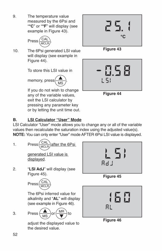
52
9. The temperature value measured by the 6Psi and “°C” or “°F” will display (see example in Figure 43).
Press .
10. The 6Psi generated LSI value will display (see example in Figure 44).
To store this LSI value in
memory, press .
If you do not wish to change any of the variable values, exit the LSI calculator by pressing any parameter key or by letting the unit time out.
B. LSI Calculator “User” ModeLSI Calculator “User” mode allows you to change any or all of the variable values then recalculate the saturation index using the adjusted value(s).NOTE: You can only enter “User” mode AFTER 6Psi LSI value is displayed.
1. Press after the 6Psi
generated LSI value is displayed.
2. “LSI AdJ” will display (see Figure 45).
Press .
The 6Psi inferred value for alkalinity and “AL” will display (see example in Figure 46).
3. Press or to
adjust the displayed value to the desired value.
Figure 43
°C
Figure 44
Figure 45
Figure 46

53
Press to accept
the value displayed.
The 6Psi inferred value for hardness and “hrd” will display (see example in Figure 47).
4. Press the or keys to adjust the displayed
value to the desired value.
Press to accept the value displayed.
The pH value measured by the 6Psi and “Ph” will display (see example in Figure 48).
5. Press the or
keys to adjust the displayed value to the desired value.
Press to accept the value displayed.
The value for temperature measured by the 6Psi and “°C” or “°F” will display (see example in Figure 49).
6. Press the or
keys to adjust the displayed value to the desired value.
Press to accept the
value displayed.
“User”, the user adjusted LSI value and “LSI” will display (see example in Figure 50). Figure 50
User
Figure 47
Figure 48
Figure 49
°C
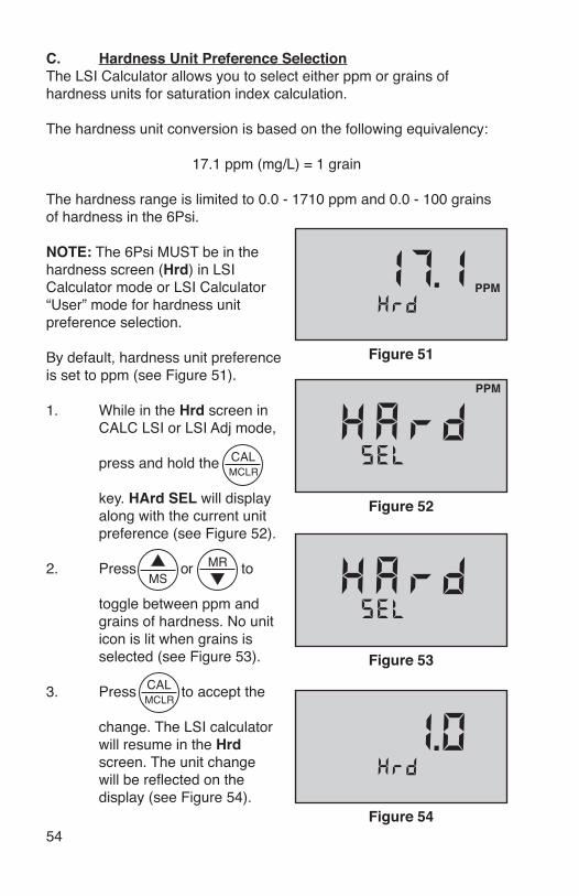
C. hardness Unit Preference SelectionThe LSI Calculator allows you to select either ppm or grains of hardness units for saturation index calculation.
The hardness unit conversion is based on the following equivalency:
17.1 ppm (mg/L) = 1 grain
The hardness range is limited to 0.0 - 1710 ppm and 0.0 - 100 grains of hardness in the 6Psi.
NOTE: The 6Psi MUST be in the hardness screen (hrd) in LSI Calculator mode or LSI Calculator “User” mode for hardness unit preference selection.
By default, hardness unit preference is set to ppm (see Figure 51).
1. While in the hrd screen in CALC LSI or LSI Adj mode,
press and hold the
key. hArd SEL will display along with the current unit preference (see Figure 52).
2. Press or to
toggle between ppm and grains of hardness. No unit icon is lit when grains is selected (see Figure 53).
3. Press to accept the
change. The LSI calculator will resume in the hrd screen. The unit change will be reflected on the display (see Figure 54).
Figure 51
PPM
PPM
Figure 52
Figure 53
Figure 5454


MyRON L COMPANy2450 Impala Drive
Carlsbad, CA 92010-7226 USA
Tel: +1-760-438-2021Fax: +1-760-931-9189
E-Mail: [email protected] [email protected]
www.myronl.com
Made In USA
UMIIOM 08SE10


![Ultrameter Operation Manual Model 6P - [Official] Myron L ... · Ultrameter™ Operation Manual Model 6P 10 - 02 (WEB) EG MYRON L COMPANY. 7-1 1-00 Reference Junction under Glass](https://img.pdfslide.us/doc/110x75/5afd383c7f8b9a944d8d206b/ultrameter-operation-manual-model-6p-official-myron-l-operation-manual.jpg)