Embed Size (px)
Citation preview
Cat.No. V056-E1-1
Programmable TerminalNT4S/NT15S/NT18S
OPERATION MANUAL

i

ii

iii
NT4S/NT15S/NT18SProgrammable TerminalOperation ManualProduced March 1999

iv

v
OMRON Product ReferencesAll OMRON products are capitalized in this manual. The word ‘Unit’ is also capitalized when it refers to anOMRON product, regardless of whether or not it appears in the proper name of the product.
The abbreviation ‘Ch,’ which appears in some displays and on some OMRON products, often means ‘word’and is abbreviated ‘Wd’ in documentation in this sense.
The abbreviation ‘PC’ means Programmable Controller and is not used as an abbreviation for anything else.
The abbreviation ‘Host’ means a controller such as an FA computer which controls a PT (programmableterminal).
Visual AidsThe following headings appear in the left column of the manual to help you locate different types of in-formation.
Note Indicates information of particular interest for efficient and convenient operation ofthe product.
1, 2, 3... 1. Indicates lists of one sort or another, such as procedures, checklists, etc.
e OMRON, 1999All rights reserved. No part of this publication may be reproduced, stored in a retrieval system, or transmitted, in anyform, or by any means, mechanical, electronic, photocopying, recording, or otherwise, without the prior written permis-sion of OMRON.
No patent liability is assumed with respect to the use of the information contained herein. Moreover, because OMRON isconstantly striving to improve its high-quality products, the information contained in this manual is subject to changewithout notice. Every precaution has been taken in the preparation of this manual. Nevertheless, OMRON assumes noresponsibility for errors or omissions. Neither is any liability assumed for damages resulting from the use of the in-formation contained in this publication.

vi
vii
TABLE OF CONTENTS
PRECAUTIONS . . . . . . . . . . . . . . . . . . . . . . . . . . . . . . . . . . . . . . xi1 Intended Audience . . . . . . . . . . . . . . . . . . . . . . . . . . . . . . . . . . . . . . . . . . . . . . . . . . . . . . . . . . . . . . . xii2 General Precautions . . . . . . . . . . . . . . . . . . . . . . . . . . . . . . . . . . . . . . . . . . . . . . . . . . . . . . . . . . . . . . xii3 Safety Precautions . . . . . . . . . . . . . . . . . . . . . . . . . . . . . . . . . . . . . . . . . . . . . . . . . . . . . . . . . . . . . . . . xii
SECTION 1The Terminals of the NT-Series . . . . . . . . . . . . . . . . . . . . . . . . 11.1 Front View . . . . . . . . . . . . . . . . . . . . . . . . . . . . . . . . . . . . . . . . . . . . . . . . . . . . . . . . . . . . . . . . . . . . . . . 41.2 Keyboard. . . . . . . . . . . . . . . . . . . . . . . . . . . . . . . . . . . . . . . . . . . . . . . . . . . . . . . . . . . . . . . . . . . . . . . . . 81.3 Rear View. . . . . . . . . . . . . . . . . . . . . . . . . . . . . . . . . . . . . . . . . . . . . . . . . . . . . . . . . . . . . . . . . . . . . . . . 161.4 Mounting the Terminals. . . . . . . . . . . . . . . . . . . . . . . . . . . . . . . . . . . . . . . . . . . . . . . . . . . . . . . . . . . 211.5 Pin Assignments . . . . . . . . . . . . . . . . . . . . . . . . . . . . . . . . . . . . . . . . . . . . . . . . . . . . . . . . . . . . . . . . . . 311.6 Shield . . . . . . . . . . . . . . . . . . . . . . . . . . . . . . . . . . . . . . . . . . . . . . . . . . . . . . . . . . . . . . . . . . . . . . . . . . . . 361.7 Display . . . . . . . . . . . . . . . . . . . . . . . . . . . . . . . . . . . . . . . . . . . . . . . . . . . . . . . . . . . . . . . . . . . . . . . . . . . 371.8 User-Mode Switch . . . . . . . . . . . . . . . . . . . . . . . . . . . . . . . . . . . . . . . . . . . . . . . . . . . . . . . . . . . . . . . . 411.9 Battery . . . . . . . . . . . . . . . . . . . . . . . . . . . . . . . . . . . . . . . . . . . . . . . . . . . . . . . . . . . . . . . . . . . . . . . . . . . 421.10 Fuse. . . . . . . . . . . . . . . . . . . . . . . . . . . . . . . . . . . . . . . . . . . . . . . . . . . . . . . . . . . . . . . . . . . . . . . . . . . . . . 431.11 Application Memory . . . . . . . . . . . . . . . . . . . . . . . . . . . . . . . . . . . . . . . . . . . . . . . . . . . . . . . . . . . . . . 43
SECTION 2Technical Data . . . . . . . . . . . . . . . . . . . . . . . . . . . . . . . . . . . . . . . . 452.1 NT4S-SF121B-E . . . . . . . . . . . . . . . . . . . . . . . . . . . . . . . . . . . . . . . . . . . . . . . . . . . . . . . . . . . . . . . . . . 472.2 NT4S-SF122B-E . . . . . . . . . . . . . . . . . . . . . . . . . . . . . . . . . . . . . . . . . . . . . . . . . . . . . . . . . . . . . . . . . . 482.3 NT4S-SF123B-E . . . . . . . . . . . . . . . . . . . . . . . . . . . . . . . . . . . . . . . . . . . . . . . . . . . . . . . . . . . . . . . . . . 502.4 NT15S-SF121B-E . . . . . . . . . . . . . . . . . . . . . . . . . . . . . . . . . . . . . . . . . . . . . . . . . . . . . . . . . . . . . . . . . 512.5 NT18S-SF121B-E . . . . . . . . . . . . . . . . . . . . . . . . . . . . . . . . . . . . . . . . . . . . . . . . . . . . . . . . . . . . . . . . . 53
SECTION 3Operating Modes . . . . . . . . . . . . . . . . . . . . . . . . . . . . . . . . . . . . . . 553.1 Setting the Operating Mode . . . . . . . . . . . . . . . . . . . . . . . . . . . . . . . . . . . . . . . . . . . . . . . . . . . . . . . 57
SECTION 4Standard Mode . . . . . . . . . . . . . . . . . . . . . . . . . . . . . . . . . . . . . . . . 594.1 Setting the Operating Mode . . . . . . . . . . . . . . . . . . . . . . . . . . . . . . . . . . . . . . . . . . . . . . . . . . . . . . . 634.2 Startup Process . . . . . . . . . . . . . . . . . . . . . . . . . . . . . . . . . . . . . . . . . . . . . . . . . . . . . . . . . . . . . . . . . . . 644.3 Communication in the Standard Mode . . . . . . . . . . . . . . . . . . . . . . . . . . . . . . . . . . . . . . . . . . . . . 654.4 Operating Concept. . . . . . . . . . . . . . . . . . . . . . . . . . . . . . . . . . . . . . . . . . . . . . . . . . . . . . . . . . . . . . . . 654.5 Masks . . . . . . . . . . . . . . . . . . . . . . . . . . . . . . . . . . . . . . . . . . . . . . . . . . . . . . . . . . . . . . . . . . . . . . . . . . . . 704.6 Variables . . . . . . . . . . . . . . . . . . . . . . . . . . . . . . . . . . . . . . . . . . . . . . . . . . . . . . . . . . . . . . . . . . . . . . . . . 724.7 Graphics . . . . . . . . . . . . . . . . . . . . . . . . . . . . . . . . . . . . . . . . . . . . . . . . . . . . . . . . . . . . . . . . . . . . . . . . . 1244.8 Recipes. . . . . . . . . . . . . . . . . . . . . . . . . . . . . . . . . . . . . . . . . . . . . . . . . . . . . . . . . . . . . . . . . . . . . . . . . . . 1264.9 Message System . . . . . . . . . . . . . . . . . . . . . . . . . . . . . . . . . . . . . . . . . . . . . . . . . . . . . . . . . . . . . . . . . . 1364.10 Help System . . . . . . . . . . . . . . . . . . . . . . . . . . . . . . . . . . . . . . . . . . . . . . . . . . . . . . . . . . . . . . . . . . . . . . 1554.11 Function Keys . . . . . . . . . . . . . . . . . . . . . . . . . . . . . . . . . . . . . . . . . . . . . . . . . . . . . . . . . . . . . . . . . . . . 1564.12 System Parameters. . . . . . . . . . . . . . . . . . . . . . . . . . . . . . . . . . . . . . . . . . . . . . . . . . . . . . . . . . . . . . . . 1594.13 Version Number . . . . . . . . . . . . . . . . . . . . . . . . . . . . . . . . . . . . . . . . . . . . . . . . . . . . . . . . . . . . . . . . . . 1614.14 Running Time Meter. . . . . . . . . . . . . . . . . . . . . . . . . . . . . . . . . . . . . . . . . . . . . . . . . . . . . . . . . . . . . . 161
viii
4.15 Parallel Outputs . . . . . . . . . . . . . . . . . . . . . . . . . . . . . . . . . . . . . . . . . . . . . . . . . . . . . . . . . . . . . . . . . . 1634.16 Screen Saver. . . . . . . . . . . . . . . . . . . . . . . . . . . . . . . . . . . . . . . . . . . . . . . . . . . . . . . . . . . . . . . . . . . . . . 1634.17 Image of the Mask Number . . . . . . . . . . . . . . . . . . . . . . . . . . . . . . . . . . . . . . . . . . . . . . . . . . . . . . . 1644.18 Image of the Mode Selector Switch . . . . . . . . . . . . . . . . . . . . . . . . . . . . . . . . . . . . . . . . . . . . . . . . 1644.19 Terminal Clock . . . . . . . . . . . . . . . . . . . . . . . . . . . . . . . . . . . . . . . . . . . . . . . . . . . . . . . . . . . . . . . . . . . 1644.20 Read Coordination Byte . . . . . . . . . . . . . . . . . . . . . . . . . . . . . . . . . . . . . . . . . . . . . . . . . . . . . . . . . . 1664.21 Write Coordination Byte . . . . . . . . . . . . . . . . . . . . . . . . . . . . . . . . . . . . . . . . . . . . . . . . . . . . . . . . . . 1684.22 Cyclic Poll Area . . . . . . . . . . . . . . . . . . . . . . . . . . . . . . . . . . . . . . . . . . . . . . . . . . . . . . . . . . . . . . . . . . 1694.23 Control Codes . . . . . . . . . . . . . . . . . . . . . . . . . . . . . . . . . . . . . . . . . . . . . . . . . . . . . . . . . . . . . . . . . . . . 1734.24 Cyclic Variables . . . . . . . . . . . . . . . . . . . . . . . . . . . . . . . . . . . . . . . . . . . . . . . . . . . . . . . . . . . . . . . . . . 1754.25 Interface Parameters . . . . . . . . . . . . . . . . . . . . . . . . . . . . . . . . . . . . . . . . . . . . . . . . . . . . . . . . . . . . . . 1754.26 Variable Definition . . . . . . . . . . . . . . . . . . . . . . . . . . . . . . . . . . . . . . . . . . . . . . . . . . . . . . . . . . . . . . . 1754.27 Application Programming . . . . . . . . . . . . . . . . . . . . . . . . . . . . . . . . . . . . . . . . . . . . . . . . . . . . . . . . . 1764.28 Downloading the User Description . . . . . . . . . . . . . . . . . . . . . . . . . . . . . . . . . . . . . . . . . . . . . . . . 1804.29 Simulation without the Controller . . . . . . . . . . . . . . . . . . . . . . . . . . . . . . . . . . . . . . . . . . . . . . . . . 184
SECTION 5Transparent Mode . . . . . . . . . . . . . . . . . . . . . . . . . . . . . . . . . . . . . 1855.1 Setting the Operating Mode . . . . . . . . . . . . . . . . . . . . . . . . . . . . . . . . . . . . . . . . . . . . . . . . . . . . . . . 1875.2 Start-up Processes . . . . . . . . . . . . . . . . . . . . . . . . . . . . . . . . . . . . . . . . . . . . . . . . . . . . . . . . . . . . . . . . 1875.3 Communication in the Transparent Mode. . . . . . . . . . . . . . . . . . . . . . . . . . . . . . . . . . . . . . . . . . 1885.4 Function Setup Menu . . . . . . . . . . . . . . . . . . . . . . . . . . . . . . . . . . . . . . . . . . . . . . . . . . . . . . . . . . . . . 1895.5 Display . . . . . . . . . . . . . . . . . . . . . . . . . . . . . . . . . . . . . . . . . . . . . . . . . . . . . . . . . . . . . . . . . . . . . . . . . . . 1915.6 Keys . . . . . . . . . . . . . . . . . . . . . . . . . . . . . . . . . . . . . . . . . . . . . . . . . . . . . . . . . . . . . . . . . . . . . . . . . . . . . 1925.7 Interface Control Characters . . . . . . . . . . . . . . . . . . . . . . . . . . . . . . . . . . . . . . . . . . . . . . . . . . . . . . 1935.8 Error Messages . . . . . . . . . . . . . . . . . . . . . . . . . . . . . . . . . . . . . . . . . . . . . . . . . . . . . . . . . . . . . . . . . . . 197
SECTION 6Linking to OMRON Controllers . . . . . . . . . . . . . . . . . . . . . . . . 1996.1 OMRON Host-Link . . . . . . . . . . . . . . . . . . . . . . . . . . . . . . . . . . . . . . . . . . . . . . . . . . . . . . . . . . . . . . 2016.2 OMRON NT-Link . . . . . . . . . . . . . . . . . . . . . . . . . . . . . . . . . . . . . . . . . . . . . . . . . . . . . . . . . . . . . . . . 205
INDEX. . . . . . . . . . . . . . . . . . . . . . . . . . . . . . . . . . . . . . . . . . . . . . . . 213Revision History . . . . . . . . . . . . . . . . . . . . . . . . . . . . . . . . . . . . . . . 217
ix
About this Manual:
This manual describes the basic functions and operation procedures of the NT-series programmable terminalNT4S/NT15S/NT18S, its operations when connected to a PC or a Host, and includes the sections describedbelow.
Please read this manual carefully and be sure you understand the information provided before attempting toinstall and operate the NT-series programmable terminal NT4S/NT15S/NT18S.
Section 1 describes the physical size of the terminals and the electrical connections.
Section 2 describes the electrical and mechanical specifications of the terminals.
Section 3 describes the two operation modes, the standard mode and transparant mode and how to setthese.
Section 4 describes the standard mode in detail.
Section 5 describes the transparant mode in detail.
Section 6 describes how to connect to OMRON PLC using hostlink or NT-Link.
x
Related Manuals and Their Contents:
The related manuals are listed below.
The n symbol at the end of the manual number is the revision history number.
[Operating the programmable terminal and communicating with the host]
N NT4S/NT15S/NT18S Programmable Terminal Operation Manual(V056-E1-n) . . . . . . . . . . . . . . . . . . . . . . . . . . . . . . . . . . . . . . . . . . . . . . . . . . . . This manual
This operation manual is the manual for the NT4S/NT15S/NT18S itself.
This operation manual describes the functions and handling of both the program-mable terminal body and the host interface function.
[Connecting the NT4S/NT15S/NT18S to PLC’s other than Omron.]
N NT4S/NT15S/NT18S Programmable terminal, multi-vendor connections(V058-E1-n)
The NT4S/NT15S/NT18S can also be connected to other PLC’s then Omron only.This manual describes how to connect to other PLC’s.

xi
PRECAUTIONS
This section provides general precautions for using the Programmable Terminal.
The information contained in this section is important for the safe and reliable application of the ProgrammableTerminal. You must read this section and understand the information contained before attempting to set up oroperate a Programmable Terminal.
1 Intended Audience . . . . . . . . . . . . . . . . . . . . . . . . . . . . . . . . . . . . . . . . . . . . . . . . . . . . . . . . . . . . . . . . . . xii2 General Precautions . . . . . . . . . . . . . . . . . . . . . . . . . . . . . . . . . . . . . . . . . . . . . . . . . . . . . . . . . . . . . . . . . xii3 Safety Precautions . . . . . . . . . . . . . . . . . . . . . . . . . . . . . . . . . . . . . . . . . . . . . . . . . . . . . . . . . . . . . . . . . . . xii
xii
Precautions
1 Intended AudienceThis manual is intended for the following personnel, who must also have knowl-edge of electrical systems (an electrical engineer or the equivalent).
N Personnel in charge of introducing FA systems into production facilities.
N Personnel in charge of designing FA systems.
N Personnel in charge of installing and connecting FA systems.
N Personnel in charge of managing FA systems and facilities.
2 General PrecautionsThe user must operate the product according to the performance specificationsdescribed in the operation manuals.Before using the product under conditions which are not described in the manual orapplying the product to nuclear control systems, railroad systems, aviation sys-tems, vehicles, combustion systems, medical equipment, amusement machines,safety equipment, and other systems, machines and equipment that may have aserious influence on lives and property if used improperly, consult your OMRONrepresentative.Make sure that the ratings and performance characteristics of the product are suffi-cient for the systems, machines, and equipment, and be sure to provide the sys-tems, machines, and equipment with double safety mechanisms.This manual provides information for using the Programmable Terminal. Be sure toread this manual before attempting to use the software and keep this manual closeat hand for reference during operation.
WARNING It is extremely important that Programmable Terminals and related devices beused for the specified purpose and under the specified conditions, especially inapplications that can directly or indirectly affect human life. You must consult withyour OMRON representative before applying Programmable Terminals to theabove-mentioned applications.
WARNING Do not use input functions such as PT keys for applications where danger to humanlife or serious damage is possible, or for emergency switch applications.
3 Safety PrecautionsRead these safety precautions carefully and make sure you understand them be-fore using the Programmable Terminal so that you can use it safely and correctly.
Safety Conventions andtheir Meanings This operation manual uses the following conventions and symbols to indicate
cautions, warnings, and dangers in order to esure safe use of the NT4S/NT15S/NT18S.The caustions, warnings, and dangers shown here contain important informationrelated to safety. This instructions in these cautions, warnings, and dangers mustbe observed.
xiii
Precautions
The conventions used and their meanings are presented below.
WARNING Indicates information that, if not heeded, could possibly result in loss of life or seri-ous injury.
CAUTION Indicates information that, if not heeded, could result in relatively serious or minorinjury, damage to the product, or faulty operation.
Explanation of SymbolsThis manual uses the following symbols to indicate notes and hazardous situations.
Notes for the User
General Danger
Specific Danger

xiv
1
SECTION 1The Terminals of the NT-Series
This section describes the terminal hardware. This includes all the drawings, the description of the function ofthe keys, the electrical connections and the dip-switch settings. It also describes how to mount the terminal.Furthermore it describes how to handle the battery.
1.1 Front View . . . . . . . . . . . . . . . . . . . . . . . . . . . . . . . . . . . . . . . . . . . . . . . . . . . . . . . . . . . . . . . . . . . . . . . . . . . . . . . . . 41.1.1 NT4S-SF121B-E . . . . . . . . . . . . . . . . . . . . . . . . . . . . . . . . . . . . . . . . . . . . . . . . . . . . . . . . . . . . . . . . . . . . . 41.1.2 NT4S-SF122B-E . . . . . . . . . . . . . . . . . . . . . . . . . . . . . . . . . . . . . . . . . . . . . . . . . . . . . . . . . . . . . . . . . . . . . 51.1.3 NT4S-SF123B-E . . . . . . . . . . . . . . . . . . . . . . . . . . . . . . . . . . . . . . . . . . . . . . . . . . . . . . . . . . . . . . . . . . . . . 61.1.4 NT15S-SF121B-E . . . . . . . . . . . . . . . . . . . . . . . . . . . . . . . . . . . . . . . . . . . . . . . . . . . . . . . . . . . . . . . . . . . . 71.1.5 NT18S-SF121B-E . . . . . . . . . . . . . . . . . . . . . . . . . . . . . . . . . . . . . . . . . . . . . . . . . . . . . . . . . . . . . . . . . . . . 8
1.2 Keyboard . . . . . . . . . . . . . . . . . . . . . . . . . . . . . . . . . . . . . . . . . . . . . . . . . . . . . . . . . . . . . . . . . . . . . . . . . . . . . . . . . . . 81.2.1 Editing Keys. . . . . . . . . . . . . . . . . . . . . . . . . . . . . . . . . . . . . . . . . . . . . . . . . . . . . . . . . . . . . . . . . . . . . . . . . 91.2.2 Control Keys . . . . . . . . . . . . . . . . . . . . . . . . . . . . . . . . . . . . . . . . . . . . . . . . . . . . . . . . . . . . . . . . . . . . . . . . 101.2.3 Special Keys . . . . . . . . . . . . . . . . . . . . . . . . . . . . . . . . . . . . . . . . . . . . . . . . . . . . . . . . . . . . . . . . . . . . . . . . . 101.2.4 Function Keys . . . . . . . . . . . . . . . . . . . . . . . . . . . . . . . . . . . . . . . . . . . . . . . . . . . . . . . . . . . . . . . . . . . . . . . 11
1.2.4.1 Function Key Arrangement . . . . . . . . . . . . . . . . . . . . . . . . . . . . . . . . . . . . . . . . . . . . . . . . . 111.2.4.1.1 NT4S-SF121B-E . . . . . . . . . . . . . . . . . . . . . . . . . . . . . . . . . . . . . . . . . . . . . . . . . 111.2.4.1.2 NT4S-SF122B-E . . . . . . . . . . . . . . . . . . . . . . . . . . . . . . . . . . . . . . . . . . . . . . . . . 121.2.4.1.3 NT4S-SF123B-E . . . . . . . . . . . . . . . . . . . . . . . . . . . . . . . . . . . . . . . . . . . . . . . . . 121.2.4.1.4 NT15S-SF121B-E . . . . . . . . . . . . . . . . . . . . . . . . . . . . . . . . . . . . . . . . . . . . . . . . 131.2.4.1.5 NT18S-SF121B-E . . . . . . . . . . . . . . . . . . . . . . . . . . . . . . . . . . . . . . . . . . . . . . . . 13
1.2.5 Slide-in Identification Strips for the Function Keys . . . . . . . . . . . . . . . . . . . . . . . . . . . . . . . . . . . . 141.2.5.1 NT4S-SF121B-E . . . . . . . . . . . . . . . . . . . . . . . . . . . . . . . . . . . . . . . . . . . . . . . . . . . . . . . . . . . . 141.2.5.2 NT4S-SF122B-E . . . . . . . . . . . . . . . . . . . . . . . . . . . . . . . . . . . . . . . . . . . . . . . . . . . . . . . . . . . . 141.2.5.3 NT4S-SF123B-E . . . . . . . . . . . . . . . . . . . . . . . . . . . . . . . . . . . . . . . . . . . . . . . . . . . . . . . . . . . . 151.2.5.4 NT15S-SF121B-E . . . . . . . . . . . . . . . . . . . . . . . . . . . . . . . . . . . . . . . . . . . . . . . . . . . . . . . . . . . 151.2.5.5 NT18S-SF121B-E . . . . . . . . . . . . . . . . . . . . . . . . . . . . . . . . . . . . . . . . . . . . . . . . . . . . . . . . . . . 15
1.3 Rear View . . . . . . . . . . . . . . . . . . . . . . . . . . . . . . . . . . . . . . . . . . . . . . . . . . . . . . . . . . . . . . . . . . . . . . . . . . . . . . . . . . 161.3.1 NT4S-SF121B-E . . . . . . . . . . . . . . . . . . . . . . . . . . . . . . . . . . . . . . . . . . . . . . . . . . . . . . . . . . . . . . . . . . . . . 161.3.2 NT4S-SF122B-E . . . . . . . . . . . . . . . . . . . . . . . . . . . . . . . . . . . . . . . . . . . . . . . . . . . . . . . . . . . . . . . . . . . . . 171.3.3 NT4S-SF123B-E . . . . . . . . . . . . . . . . . . . . . . . . . . . . . . . . . . . . . . . . . . . . . . . . . . . . . . . . . . . . . . . . . . . . . 181.3.4 NT15S-SF121B-E . . . . . . . . . . . . . . . . . . . . . . . . . . . . . . . . . . . . . . . . . . . . . . . . . . . . . . . . . . . . . . . . . . . . 191.3.5 NT18S-SF121B-E . . . . . . . . . . . . . . . . . . . . . . . . . . . . . . . . . . . . . . . . . . . . . . . . . . . . . . . . . . . . . . . . . . . . 20
1.4 Mounting the Terminals . . . . . . . . . . . . . . . . . . . . . . . . . . . . . . . . . . . . . . . . . . . . . . . . . . . . . . . . . . . . . . . . . . . . . 211.4.1 Front Panel Dimensions. . . . . . . . . . . . . . . . . . . . . . . . . . . . . . . . . . . . . . . . . . . . . . . . . . . . . . . . . . . . . . 22
1.4.1.1 NT4S-SF121B-E . . . . . . . . . . . . . . . . . . . . . . . . . . . . . . . . . . . . . . . . . . . . . . . . . . . . . . . . . . . . 221.4.1.2 NT4S-SF122B-E . . . . . . . . . . . . . . . . . . . . . . . . . . . . . . . . . . . . . . . . . . . . . . . . . . . . . . . . . . . . 221.4.1.3 NT4S-SF123B-E . . . . . . . . . . . . . . . . . . . . . . . . . . . . . . . . . . . . . . . . . . . . . . . . . . . . . . . . . . . . 231.4.1.4 NT15S-SF121B-E . . . . . . . . . . . . . . . . . . . . . . . . . . . . . . . . . . . . . . . . . . . . . . . . . . . . . . . . . . . 231.4.1.5 NT18S-SF121B-E . . . . . . . . . . . . . . . . . . . . . . . . . . . . . . . . . . . . . . . . . . . . . . . . . . . . . . . . . . . 24
1.4.2 Side View, Mounting Depth . . . . . . . . . . . . . . . . . . . . . . . . . . . . . . . . . . . . . . . . . . . . . . . . . . . . . . . . . . 241.4.2.1 NT4S-SF121B-E . . . . . . . . . . . . . . . . . . . . . . . . . . . . . . . . . . . . . . . . . . . . . . . . . . . . . . . . . . . . 241.4.2.2 NT4S-SF122B-E . . . . . . . . . . . . . . . . . . . . . . . . . . . . . . . . . . . . . . . . . . . . . . . . . . . . . . . . . . . . 251.4.2.3 NT4S-SF123B-E . . . . . . . . . . . . . . . . . . . . . . . . . . . . . . . . . . . . . . . . . . . . . . . . . . . . . . . . . . . . 261.4.2.4 NT15S-SF121B-E . . . . . . . . . . . . . . . . . . . . . . . . . . . . . . . . . . . . . . . . . . . . . . . . . . . . . . . . . . . 271.4.2.5 NT18S-SF121B-E . . . . . . . . . . . . . . . . . . . . . . . . . . . . . . . . . . . . . . . . . . . . . . . . . . . . . . . . . . . 28
2
1.4.3 Panel Cutout . . . . . . . . . . . . . . . . . . . . . . . . . . . . . . . . . . . . . . . . . . . . . . . . . . . . . . . . . . . . . . . . . . . . . . . . 291.4.3.1 NT4S-SF121B-E . . . . . . . . . . . . . . . . . . . . . . . . . . . . . . . . . . . . . . . . . . . . . . . . . . . . . . . . . . . . 291.4.3.2 NT4S-SF122B-E . . . . . . . . . . . . . . . . . . . . . . . . . . . . . . . . . . . . . . . . . . . . . . . . . . . . . . . . . . . . 291.4.3.3 NT4S-SF123B-E . . . . . . . . . . . . . . . . . . . . . . . . . . . . . . . . . . . . . . . . . . . . . . . . . . . . . . . . . . . . 301.4.3.4 NT15S-SF121B-E . . . . . . . . . . . . . . . . . . . . . . . . . . . . . . . . . . . . . . . . . . . . . . . . . . . . . . . . . . . 301.4.3.5 NT18S-SF121B-E . . . . . . . . . . . . . . . . . . . . . . . . . . . . . . . . . . . . . . . . . . . . . . . . . . . . . . . . . . . 31
1.5 Pin Assignments . . . . . . . . . . . . . . . . . . . . . . . . . . . . . . . . . . . . . . . . . . . . . . . . . . . . . . . . . . . . . . . . . . . . . . . . . . . . 311.5.1 Pin Assignment X1 Supply Voltage . . . . . . . . . . . . . . . . . . . . . . . . . . . . . . . . . . . . . . . . . . . . . . . . . . . 321.5.2 Pin Assignment X3 SER1 TTY / 20 mA Current Loop . . . . . . . . . . . . . . . . . . . . . . . . . . . . . . . . 331.5.3 Pin Assignment X3 SER1 RS485 . . . . . . . . . . . . . . . . . . . . . . . . . . . . . . . . . . . . . . . . . . . . . . . . . . . . . 341.5.4 Pin Assignment X3 SER1 RS232c . . . . . . . . . . . . . . . . . . . . . . . . . . . . . . . . . . . . . . . . . . . . . . . . . . . . 351.5.5 Pin Assignment X3 SER2 RS232c . . . . . . . . . . . . . . . . . . . . . . . . . . . . . . . . . . . . . . . . . . . . . . . . . . . . 351.5.6 Pin Assignment X4 Parallel Outputs . . . . . . . . . . . . . . . . . . . . . . . . . . . . . . . . . . . . . . . . . . . . . . . . . . 36
1.6 Shield. . . . . . . . . . . . . . . . . . . . . . . . . . . . . . . . . . . . . . . . . . . . . . . . . . . . . . . . . . . . . . . . . . . . . . . . . . . . . . . . . . . . . . . 361.7 Display . . . . . . . . . . . . . . . . . . . . . . . . . . . . . . . . . . . . . . . . . . . . . . . . . . . . . . . . . . . . . . . . . . . . . . . . . . . . . . . . . . . . . 37
1.7.1 NT4S-SF121B-E, NT4S-SF122B-E, NT4S-SF123B-E . . . . . . . . . . . . . . . . . . . . . . . . . . . . . . . . . . 371.7.2 NT15S-SF121B-E . . . . . . . . . . . . . . . . . . . . . . . . . . . . . . . . . . . . . . . . . . . . . . . . . . . . . . . . . . . . . . . . . . . . 371.7.3 NT18S-SF121B-E . . . . . . . . . . . . . . . . . . . . . . . . . . . . . . . . . . . . . . . . . . . . . . . . . . . . . . . . . . . . . . . . . . . . 381.7.4 Contrast Setting . . . . . . . . . . . . . . . . . . . . . . . . . . . . . . . . . . . . . . . . . . . . . . . . . . . . . . . . . . . . . . . . . . . . . 381.7.5 Default Contrast Setting . . . . . . . . . . . . . . . . . . . . . . . . . . . . . . . . . . . . . . . . . . . . . . . . . . . . . . . . . . . . . 381.7.6 Character Attributes . . . . . . . . . . . . . . . . . . . . . . . . . . . . . . . . . . . . . . . . . . . . . . . . . . . . . . . . . . . . . . . . . 39
1.7.6.1 Font Normal. . . . . . . . . . . . . . . . . . . . . . . . . . . . . . . . . . . . . . . . . . . . . . . . . . . . . . . . . . . . . . . . 391.7.6.2 Font Zoom . . . . . . . . . . . . . . . . . . . . . . . . . . . . . . . . . . . . . . . . . . . . . . . . . . . . . . . . . . . . . . . . . 391.7.6.3 ASCII Character Set Table. . . . . . . . . . . . . . . . . . . . . . . . . . . . . . . . . . . . . . . . . . . . . . . . . . 40
1.8 User-Mode Switch . . . . . . . . . . . . . . . . . . . . . . . . . . . . . . . . . . . . . . . . . . . . . . . . . . . . . . . . . . . . . . . . . . . . . . . . . . 411.9 Battery . . . . . . . . . . . . . . . . . . . . . . . . . . . . . . . . . . . . . . . . . . . . . . . . . . . . . . . . . . . . . . . . . . . . . . . . . . . . . . . . . . . . . 421.10 Fuse . . . . . . . . . . . . . . . . . . . . . . . . . . . . . . . . . . . . . . . . . . . . . . . . . . . . . . . . . . . . . . . . . . . . . . . . . . . . . . . . . . . . . . . . 431.11 Application Memory . . . . . . . . . . . . . . . . . . . . . . . . . . . . . . . . . . . . . . . . . . . . . . . . . . . . . . . . . . . . . . . . . . . . . . . . 43
3
The Terminals of the NT-Series Section 1
1 The Terminals of the NT-SeriesThis manual is only valid for the following operating terminals:
- NT4S-SF121B-E- NT4S-SF122B-E- NT4S-SF123B-E- NT15S-SF121B-E- NT18S-SF121B-E
The terminals of the NT-series are the favourite Man-Machine-Interfaces for allapplications, where an optimum relation of size to function is needed.All terminals of the NT-series permit sealed installation in accordance with the IP65degree of protection.
Each terminal is equipped with function keys, that can be individually labelled withslide-in strips.A built-in lithium battery buffers the data in the RAM and also supplies the real timeclock with power.The discharge state of the battery is monitored constantly by the system.
The communication with a controller and logging printer is supported by a universalinterface, unique for all terminals of the NT-series.
The operator guidance is done by means of a comfortable programming software.
4
The Terminals of the NT-Series Section 1-1
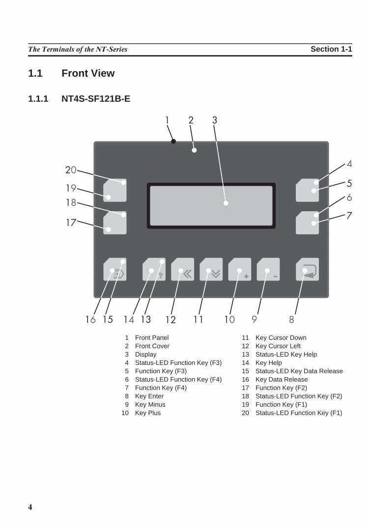
1.1 Front View
1.1.1 NT4S-SF121B-E
1 Front Panel2 Front Cover3 Display4 Status-LED Function Key (F3)5 Function Key (F3)6 Status-LED Function Key (F4)7 Function Key (F4)8 Key Enter9 Key Minus
10 Key Plus
11 Key Cursor Down12 Key Cursor Left13 Status-LED Key Help14 Key Help15 Status-LED Key Data Release16 Key Data Release17 Function Key (F2)18 Status-LED Function Key (F2)19 Function Key (F1)20 Status-LED Function Key (F1)
5
The Terminals of the NT-Series Section 1-1
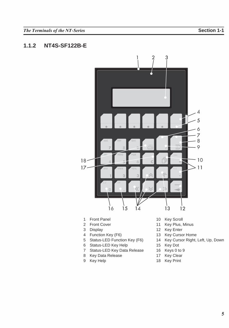
1.1.2 NT4S-SF122B-E
1 Front Panel2 Front Cover3 Display4 Function Key (F6)5 Status-LED Function Key (F6)6 Status-LED Key Help7 Status-LED Key Data Release8 Key Data Release9 Key Help
10 Key Scroll11 Key Plus, Minus12 Key Enter13 Key Cursor Home14 Key Cursor Right, Left, Up, Down15 Key Dot16 Keys 0 to 917 Key Clear18 Key Print
6
The Terminals of the NT-Series Section 1-1
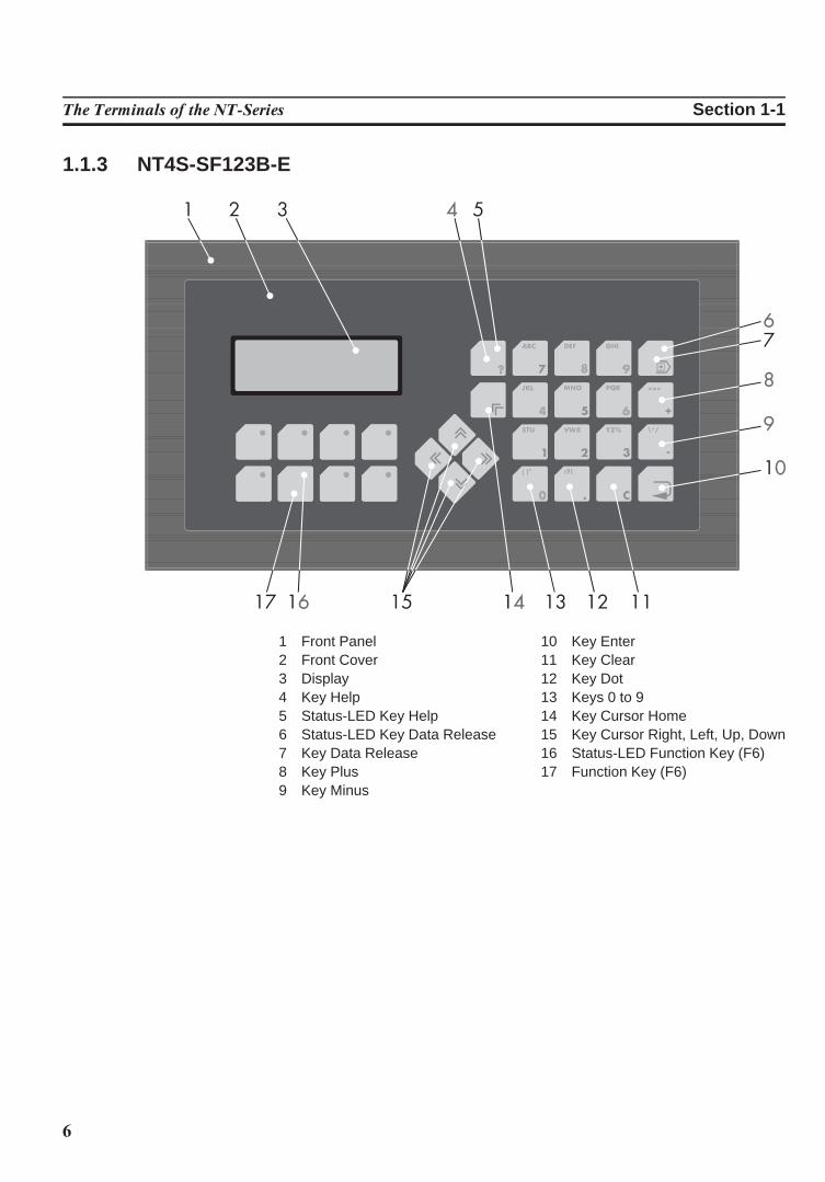
1.1.3 NT4S-SF123B-E
1 Front Panel2 Front Cover3 Display4 Key Help5 Status-LED Key Help6 Status-LED Key Data Release7 Key Data Release8 Key Plus9 Key Minus
10 Key Enter11 Key Clear12 Key Dot13 Keys 0 to 914 Key Cursor Home15 Key Cursor Right, Left, Up, Down16 Status-LED Function Key (F6)17 Function Key (F6)
7
The Terminals of the NT-Series Section 1-1
1.1.4 NT15S-SF121B-E
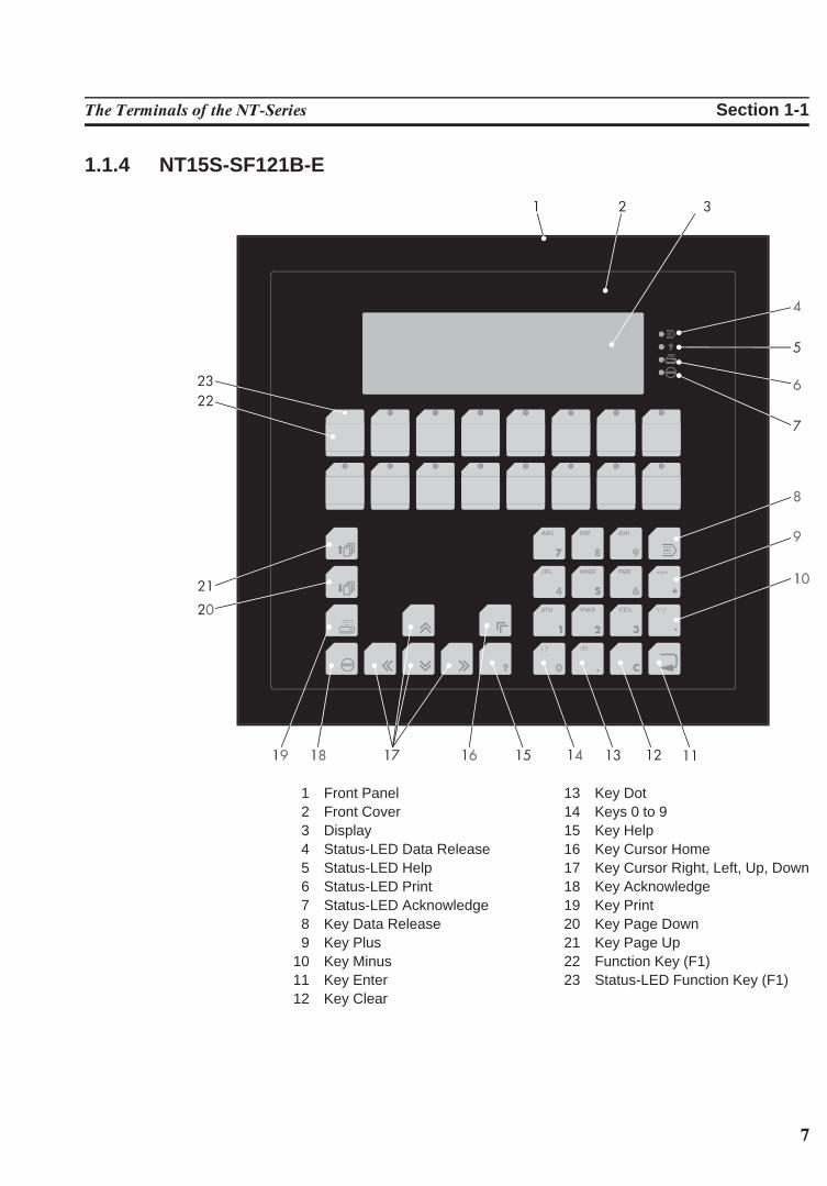
1 Front Panel2 Front Cover3 Display4 Status-LED Data Release5 Status-LED Help6 Status-LED Print7 Status-LED Acknowledge8 Key Data Release9 Key Plus
10 Key Minus11 Key Enter12 Key Clear
13 Key Dot14 Keys 0 to 915 Key Help16 Key Cursor Home17 Key Cursor Right, Left, Up, Down18 Key Acknowledge19 Key Print20 Key Page Down21 Key Page Up22 Function Key (F1)23 Status-LED Function Key (F1)
8
The Terminals of the NT-Series Section 1-1
1.1.5 NT18S-SF121B-E
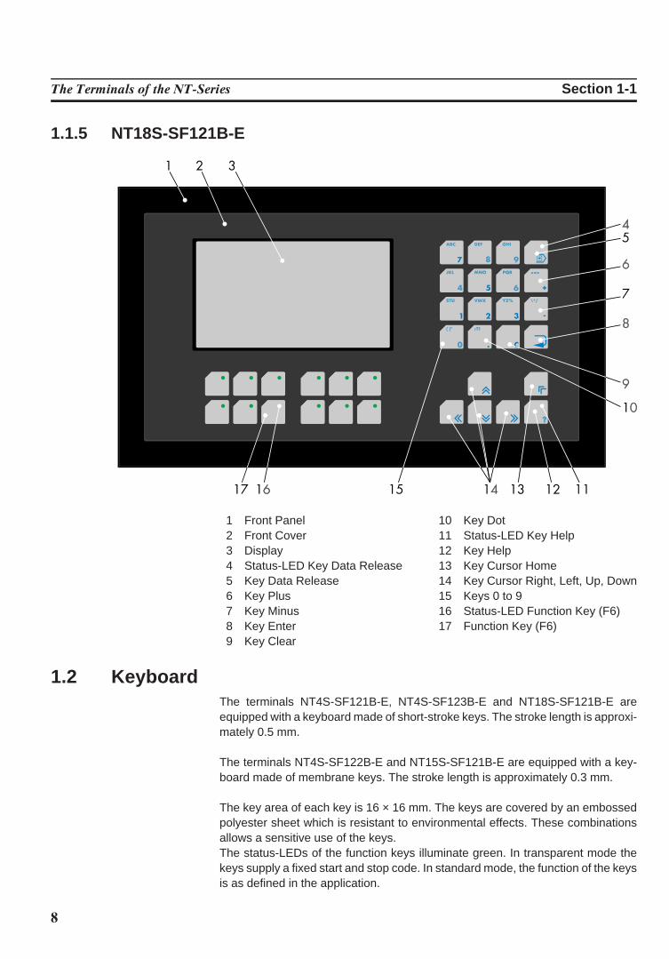
1 Front Panel2 Front Cover3 Display4 Status-LED Key Data Release5 Key Data Release6 Key Plus7 Key Minus8 Key Enter9 Key Clear
10 Key Dot11 Status-LED Key Help12 Key Help13 Key Cursor Home14 Key Cursor Right, Left, Up, Down15 Keys 0 to 916 Status-LED Function Key (F6)17 Function Key (F6)
1.2 KeyboardThe terminals NT4S-SF121B-E, NT4S-SF123B-E and NT18S-SF121B-E areequipped with a keyboard made of short-stroke keys. The stroke length is approxi-mately 0.5 mm.
The terminals NT4S-SF122B-E and NT15S-SF121B-E are equipped with a key-board made of membrane keys. The stroke length is approximately 0.3 mm.
The key area of each key is 16 × 16 mm. The keys are covered by an embossedpolyester sheet which is resistant to environmental effects. These combinationsallows a sensitive use of the keys.The status-LEDs of the function keys illuminate green. In transparent mode thekeys supply a fixed start and stop code. In standard mode, the function of the keysis as defined in the application.
9
The Terminals of the NT-Series Section 1-2
1.2.1 Editing KeysKey: 0 and ( ) ˚ is used to edit data within the editor. If the system variable Shift orShiftCase is programmed, the characters ( and ) and ˚ can be entered.
Key: 1 and STU is used to edit data within the editor. If the system variable Shift orShiftCase is programmed, the characters S and T and U can be entered.
Key: 2 and VWX is used to edit data within the editor. If the system variable Shift orShiftCase is programmed, the characters V and W and X can be entered.
Key: 3 and YZ% is used to edit data within the editor. If the system variable Shift orShiftCase is programmed, the characters Y and Z and % can be entered.
Key: 4 and JKL is used to edit data within the editor. If the system variable Shift orShiftCase is programmed, the characters J and K and L can be entered.
Key: 5 and MNO is used to edit data within the editor. If the system variable Shift orShiftCase is programmed, the characters M and N and O can be entered.
Key: 6 and PQR is used to edit data within the editor. If the system variable Shift orShiftCase is programmed, the characters P and Q and R can be entered.
Key: 7 and ABC is used to edit data within the editor. If the system variable Shift orShiftCase is programmed, the characters A and B and C can be entered.
Key: 8 and DEF is used to edit data within the editor. If the system variable Shift orShiftCase is programmed, the characters D and E and F can be entered.
Key: 9 and GHI is used to edit data within the editor. If the system variable Shift orShiftCase is programmed, the characters G and H and I can be entered.
Key: Decimal Point and :?! is used to edit data within the editor. If the systemvariable Shift or ShiftCase is programmed, the characters : and ? and ! can beentered.
Key: Minus and \*/ can be used to enter negative values within the editor. In theincrement editor, the variable value is decremented by 1. When the key is helddown, the function is repeated at a rate of repetition that is automatically increased.If the system variable Shift or ShiftCase is programmed, the characters \ and* and / can be entered.
10
The Terminals of the NT-Series Section 1-2
Key: Plus and ,=. can be used to enter positive values within the editor. In theincrement editor, the variable value is incremented by 1. When the key is helddown, the function is repeated at a rate of repetition that is automatically increased.If the system variable Shift or ShiftCase is programmed, the characters , and =and . can be entered.
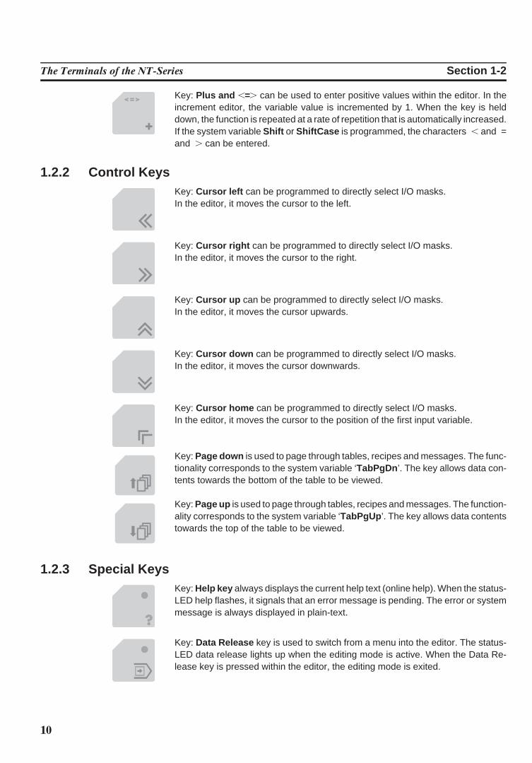
1.2.2 Control KeysKey: Cursor left can be programmed to directly select I/O masks. In the editor, it moves the cursor to the left.
Key: Cursor right can be programmed to directly select I/O masks.In the editor, it moves the cursor to the right.
Key: Cursor up can be programmed to directly select I/O masks.In the editor, it moves the cursor upwards.
Key: Cursor down can be programmed to directly select I/O masks.In the editor, it moves the cursor downwards.
Key: Cursor home can be programmed to directly select I/O masks. In the editor, it moves the cursor to the position of the first input variable.
Key: Page down is used to page through tables, recipes and messages. The func-tionality corresponds to the system variable ‘TabPgDn ’. The key allows data con-tents towards the bottom of the table to be viewed.
Key: Page up is used to page through tables, recipes and messages. The function-ality corresponds to the system variable ‘TabPgUp ’. The key allows data contentstowards the top of the table to be viewed.
1.2.3 Special KeysKey: Help key always displays the current help text (online help). When the status-LED help flashes, it signals that an error message is pending. The error or systemmessage is always displayed in plain-text.
Key: Data Release key is used to switch from a menu into the editor. The status-LED data release lights up when the editing mode is active. When the Data Re-lease key is pressed within the editor, the editing mode is exited.
11
The Terminals of the NT-Series Section 1-2
Key: Enter is used to conclude data entry. When pressed while in the startup mask,the key switches into the setup mask.
Key: Clear deletes the character beneath the cursor when it is used in an editor.Deletes the selected messages from the data memory.
Key: Acknowledge is used as an acknowledge key for the message system.
Key: Print can be used as a soft key to activate various print processes.
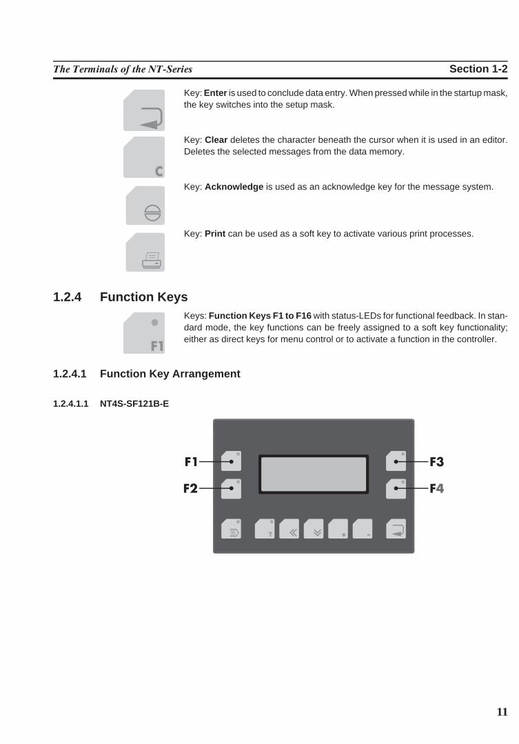
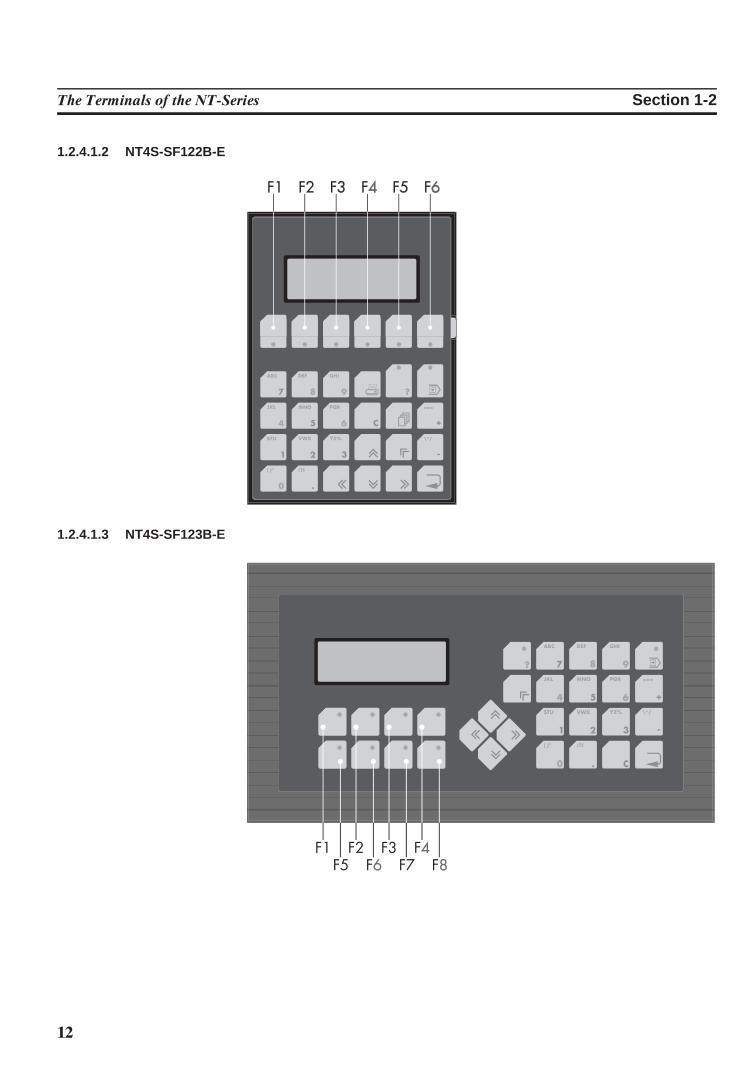
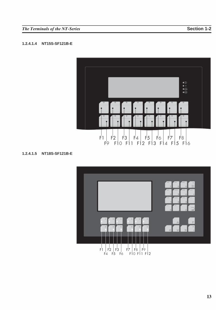
1.2.4 Function KeysKeys: Function Keys F1 to F16 with status-LEDs for functional feedback. In stan-dard mode, the key functions can be freely assigned to a soft key functionality;either as direct keys for menu control or to activate a function in the controller.
1.2.4.1 Function Key Arrangement
1.2.4.1.1 NT4S-SF121B-E
12
The Terminals of the NT-Series Section 1-2
1.2.4.1.2 NT4S-SF122B-E
1.2.4.1.3 NT4S-SF123B-E
13
The Terminals of the NT-Series Section 1-2
1.2.4.1.4 NT15S-SF121B-E
1.2.4.1.5 NT18S-SF121B-E
14
The Terminals of the NT-Series Section 1-2
1.2.5 Slide-in Identification Strips for the Function KeysThe terminals are equipped with a set of slide-in identification strips.Each set consists of ready-to-use labelled and blank slide-in identification strips.
Various labeling methods are recommended, depending on the number of termi-nals involved.
Suitable labeling methods for:
single terminal: labeling with an indelible pensmall number of terminals: transparency with laser printinglarge number of terminals: identification strips printed according to customer’s
needs
1.2.5.1 NT4S-SF121B-E
1.2.5.2 NT4S-SF122B-E
15
The Terminals of the NT-Series Section 1-2
1.2.5.3 NT4S-SF123B-E
1.2.5.4 NT15S-SF121B-E
1.2.5.5 NT18S-SF121B-E
16
The Terminals of the NT-Series Section 1-3
1.3 Rear View
1.3.1 NT4S-SF121B-E
1 Fastening Screw for Enclosure2 Mounting Bolts3 Front Panel4 Name Plate5 CE-Sign6 Note for Battery7 Warning Note8 Pin Assignment Connector X19 Connector X1 (Power Supply)
10 User-Mode Switch11 Switch Assignment User-Mode Switch12 Ground Screw13 Sign for Ground Srew14 Terminator Switch (RS485)15 Switch Assignment Terminator Switch16 Female Connector X217 Pin Assignment Female Connector X2
17
The Terminals of the NT-Series Section 1-3
1.3.2 NT4S-SF122B-E
1 Fastening Screw for Enclosure2 Female Connector X33 Terminator Switch (RS485)4 Connector X1 (Power Supply)5 Ground Screw6 Front Panel7 Switch Assignment User-Mode
Switch8 CE-Sign9 Note for Battery
10 Warning Note11 Pin Assignment Connector X112 Switch Assignment Terminator
Switch13 Pin Assignment Female Connec-
tor X314 Name Plate15 Fastening Screw for Female
Connector X3
18
The Terminals of the NT-Series Section 1-3
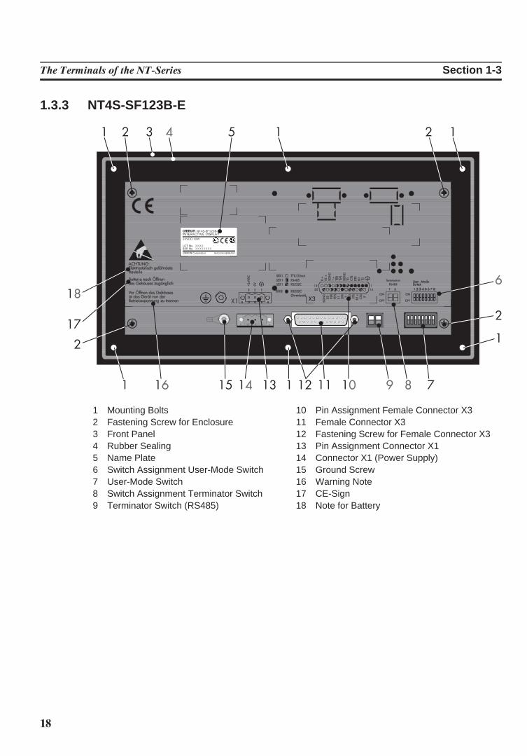
1.3.3 NT4S-SF123B-E
1 Mounting Bolts2 Fastening Screw for Enclosure3 Front Panel4 Rubber Sealing5 Name Plate6 Switch Assignment User-Mode Switch7 User-Mode Switch8 Switch Assignment Terminator Switch9 Terminator Switch (RS485)
10 Pin Assignment Female Connector X311 Female Connector X312 Fastening Screw for Female Connector X313 Pin Assignment Connector X114 Connector X1 (Power Supply)15 Ground Screw16 Warning Note17 CE-Sign18 Note for Battery
19
The Terminals of the NT-Series Section 1-3
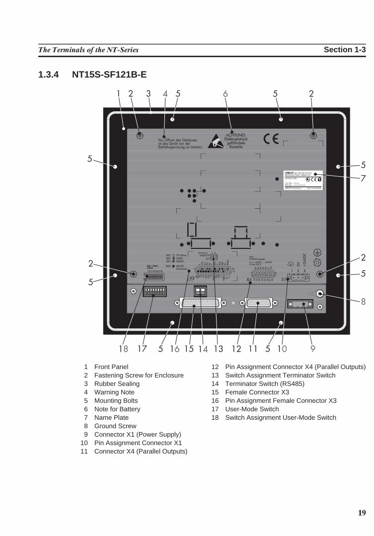
1.3.4 NT15S-SF121B-E
1 Front Panel2 Fastening Screw for Enclosure3 Rubber Sealing4 Warning Note5 Mounting Bolts6 Note for Battery7 Name Plate8 Ground Screw9 Connector X1 (Power Supply)
10 Pin Assignment Connector X111 Connector X4 (Parallel Outputs)
12 Pin Assignment Connector X4 (Parallel Outputs)13 Switch Assignment Terminator Switch14 Terminator Switch (RS485)15 Female Connector X316 Pin Assignment Female Connector X317 User-Mode Switch18 Switch Assignment User-Mode Switch
20
The Terminals of the NT-Series Section 1-3
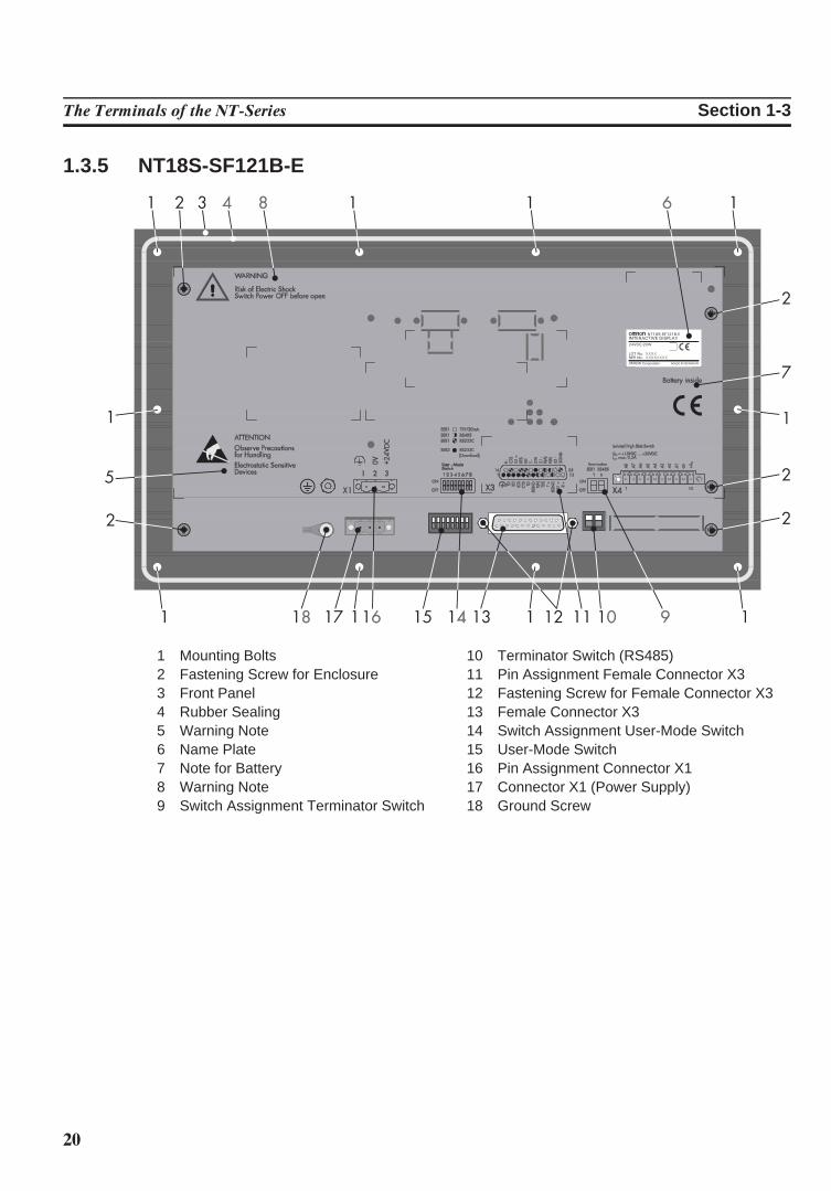
1.3.5 NT18S-SF121B-E
1 Mounting Bolts2 Fastening Screw for Enclosure3 Front Panel4 Rubber Sealing5 Warning Note6 Name Plate7 Note for Battery8 Warning Note9 Switch Assignment Terminator Switch
10 Terminator Switch (RS485)11 Pin Assignment Female Connector X312 Fastening Screw for Female Connector X313 Female Connector X314 Switch Assignment User-Mode Switch15 User-Mode Switch16 Pin Assignment Connector X117 Connector X1 (Power Supply)18 Ground Screw
21
The Terminals of the NT-Series Section 1-4
1.4 Mounting the TerminalsThe terminals with mounting bolts or lateral mounting slits are mounted from therear side. The rear panel mounting is suitable for easy and sealed installation plac-es where the rear side of the unit is accessible.
The terminal NT15S-SF121B-E is mounted from the front side. This type of in-stallation is suitable for easy and sealed installation where the rear side of the unit isnot accessible.The terminals are particularly suitable for mounting in control cabinets with amounting plate thickness of approximately 1 to 10 mm.The front panels permit sealed installation of the units in accordance with the IP65degree of protection.
The terminals- NT4S-SF123B-E- NT18S-SF121B-E- NT15S-SF121B-Ehave a circumferential groove milled into the rear side of the front plate, containinga rubber sealing.
The terminals- NT4S-SF121B-E- NT4S-SF122B-Eare equipped with a foam sealing on the rear side of the front plate.
All parts for mounting the units are supplied with the spare parts set.Special care needs to be taken during installation to maintain this high degree ofprotection. The appliance is inserted from the front through the mounting panelcutout and fastened with the fasteners of the spare parts set. The sealing must bepositioned evenly and the fastening elements tightened uniformly.When installing the terminal, keep a minimum space of 30 mm around the terminalfor adequate air circulation.
The tightness between the front panel and the mounting surface depends onthe care during installation.
Mounting and connection of the operating terminal to the power supply must becarried out by authorized and qualified personnel with EMC training.Operating terminals must be grounded according to regulations.The application-specific safety- and accident prevention regulations must be ob-served during the mounting and connection to the power supply, e.g.:
- EN 60204, Electrical Equipment of Machines- EN 292, Safety of Machinery, General Principles for Design- DIN 57 100 Part 410, Protection against Electric Shock
Hazardous voltages can exist inside electrical installations that can pose a dangerto humans. Coming in contact with live parts may result in electric shock!
22
The Terminals of the NT-Series Section 1-4
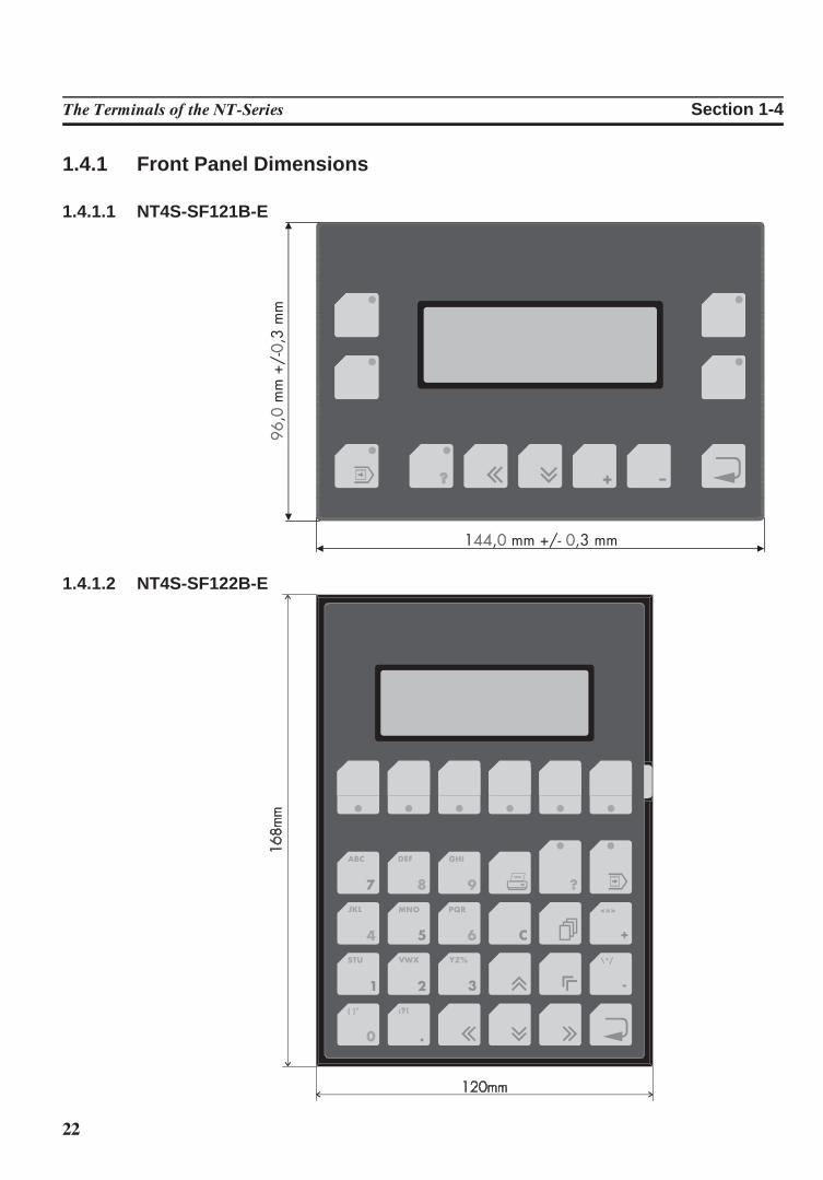
1.4.1 Front Panel Dimensions
1.4.1.1 NT4S-SF121B-E
1.4.1.2 NT4S-SF122B-E
23
The Terminals of the NT-Series Section 1-4
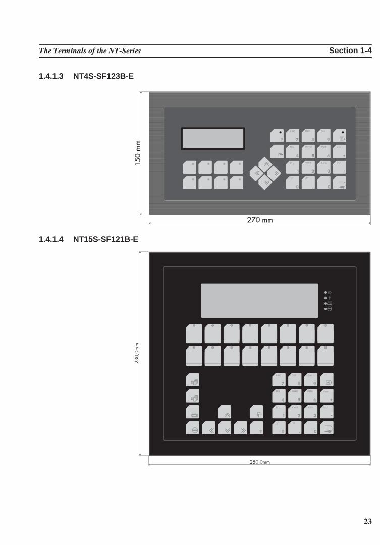
1.4.1.3 NT4S-SF123B-E
1.4.1.4 NT15S-SF121B-E
24
The Terminals of the NT-Series Section 1-4
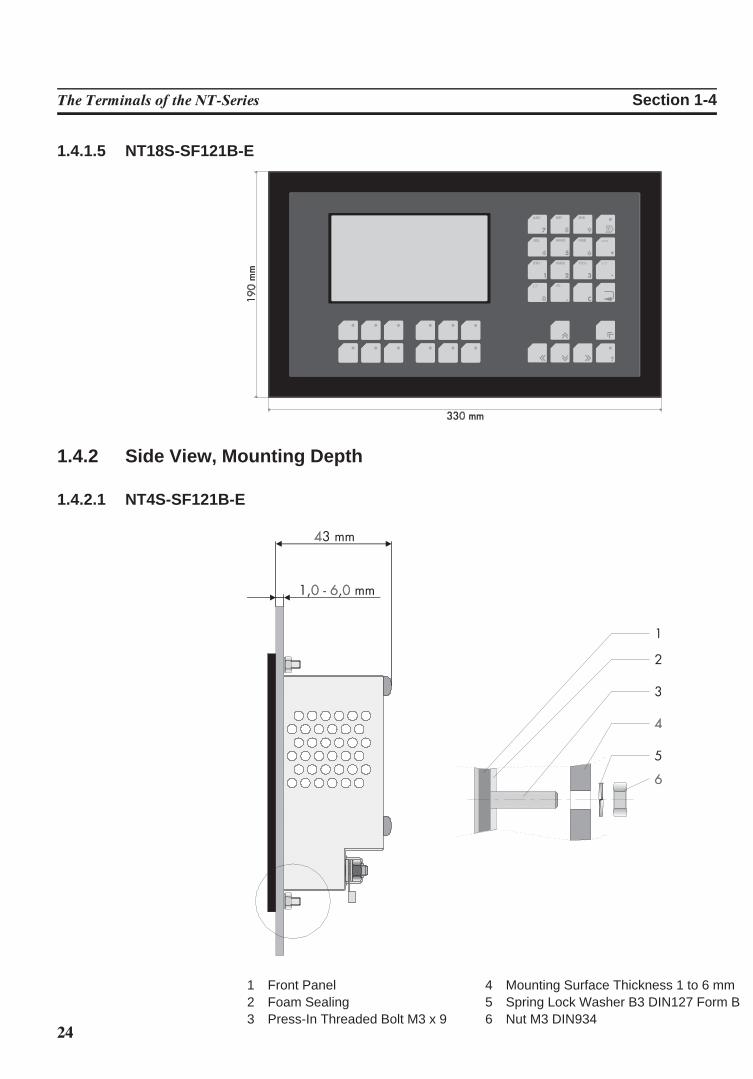
1.4.1.5 NT18S-SF121B-E
1.4.2 Side View, Mounting Depth
1.4.2.1 NT4S-SF121B-E
1 Front Panel2 Foam Sealing3 Press-In Threaded Bolt M3 x 9
4 Mounting Surface Thickness 1 to 6 mm5 Spring Lock Washer B3 DIN127 Form B6 Nut M3 DIN934
25
The Terminals of the NT-Series Section 1-4
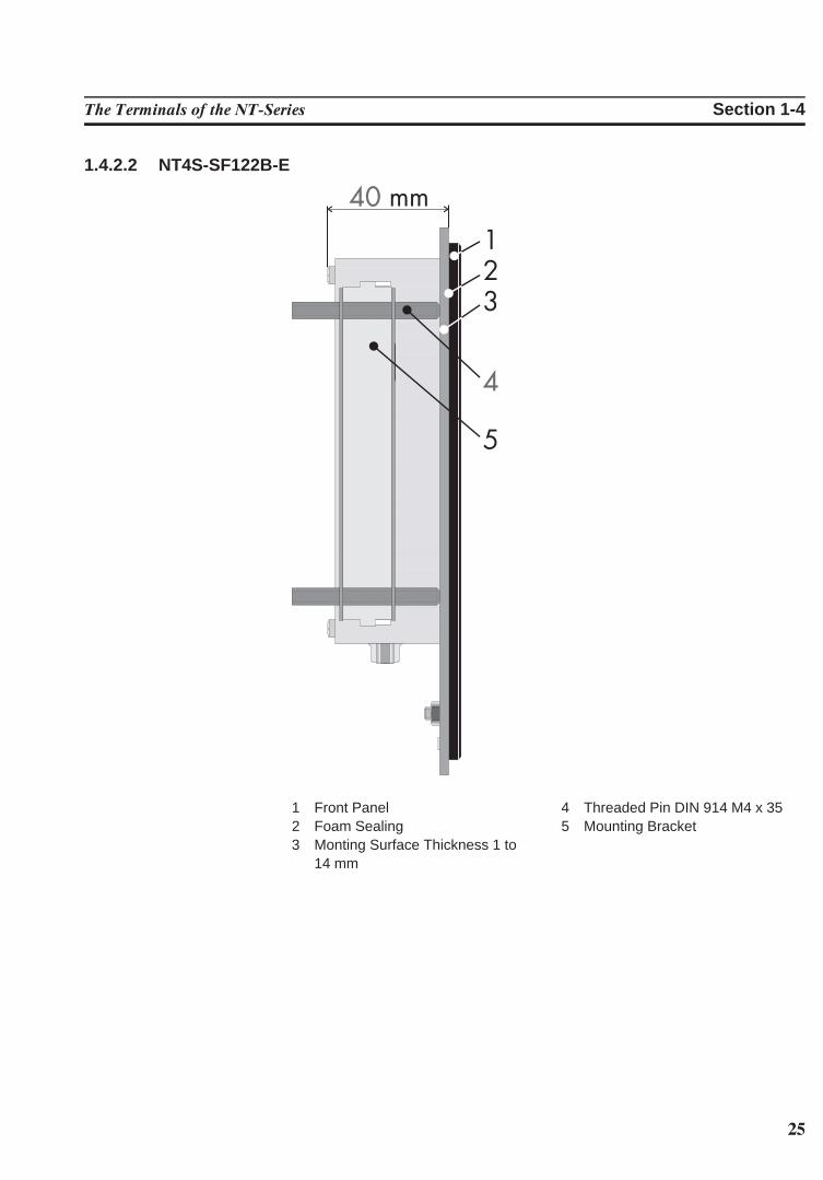
1.4.2.2 NT4S-SF122B-E
1 Front Panel2 Foam Sealing3 Monting Surface Thickness 1 to
14 mm
4 Threaded Pin DIN 914 M4 x 355 Mounting Bracket
26
The Terminals of the NT-Series Section 1-4
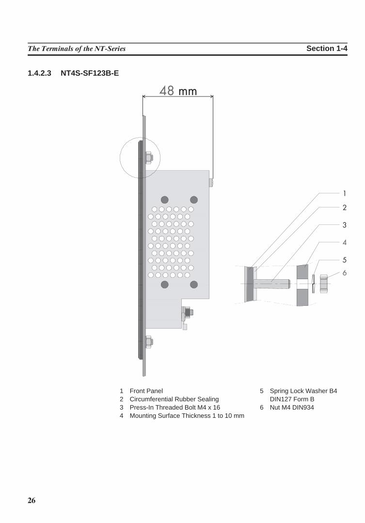
1.4.2.3 NT4S-SF123B-E
1 Front Panel2 Circumferential Rubber Sealing3 Press-In Threaded Bolt M4 x 164 Mounting Surface Thickness 1 to 10 mm
5 Spring Lock Washer B4DIN127 Form B
6 Nut M4 DIN934
27
The Terminals of the NT-Series Section 1-4
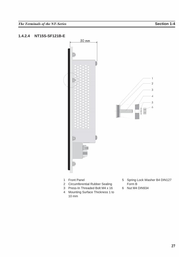
1.4.2.4 NT15S-SF121B-E
1 Front Panel2 Circumferential Rubber Sealing3 Press-In Threaded Bolt M4 x 164 Mounting Surface Thickness 1 to
10 mm
5 Spring Lock Washer B4 DIN127Form B
6 Nut M4 DIN934
28
The Terminals of the NT-Series Section 1-4
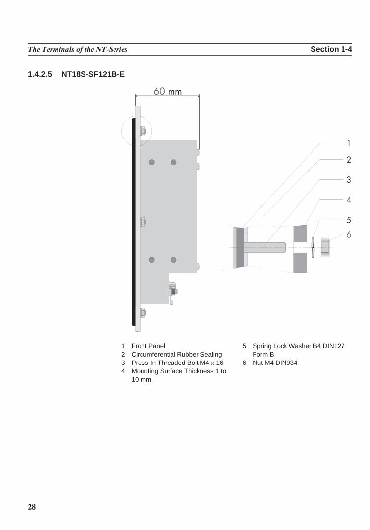
1.4.2.5 NT18S-SF121B-E
1 Front Panel2 Circumferential Rubber Sealing3 Press-In Threaded Bolt M4 x 164 Mounting Surface Thickness 1 to
10 mm
5 Spring Lock Washer B4 DIN127Form B
6 Nut M4 DIN934
29
The Terminals of the NT-Series Section 1-4
1.4.3 Panel Cutout
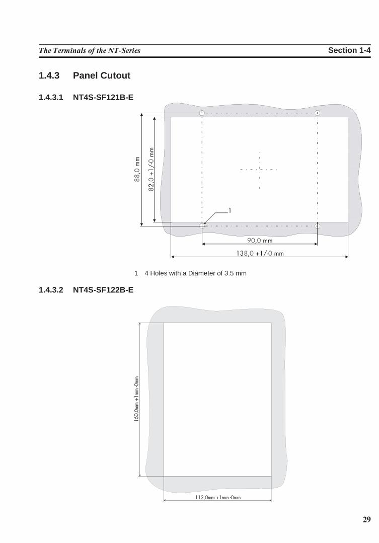
1.4.3.1 NT4S-SF121B-E
1 4 Holes with a Diameter of 3.5 mm
1.4.3.2 NT4S-SF122B-E
30
The Terminals of the NT-Series Section 1-4
1.4.3.3 NT4S-SF123B-E
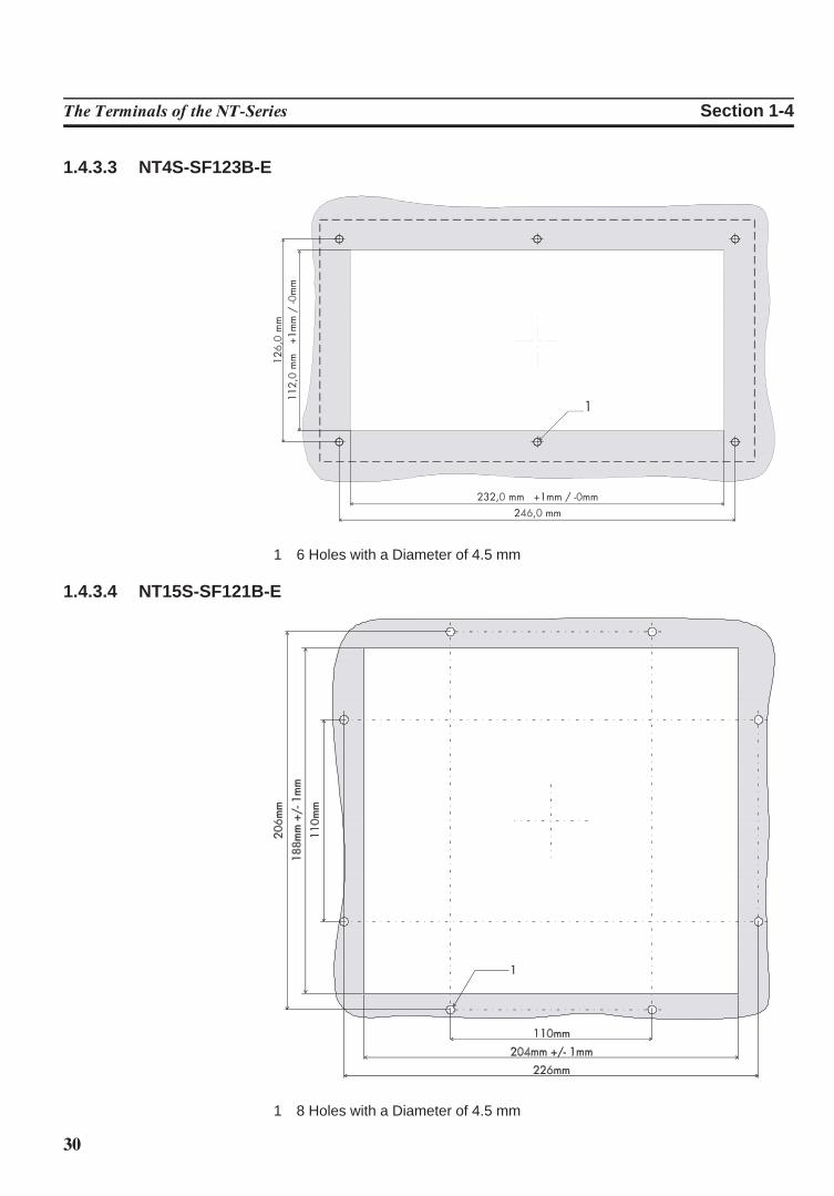
1 6 Holes with a Diameter of 4.5 mm
1.4.3.4 NT15S-SF121B-E
1 8 Holes with a Diameter of 4.5 mm
31
The Terminals of the NT-Series Section 1-5
1.4.3.5 NT18S-SF121B-E
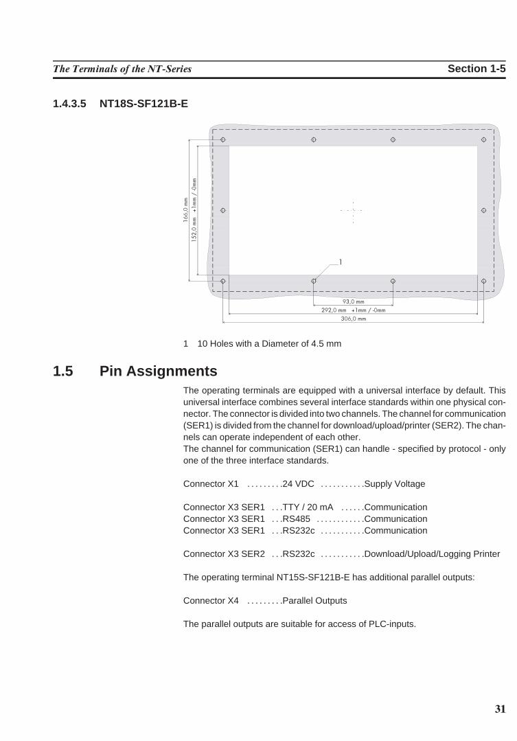
1 10 Holes with a Diameter of 4.5 mm
1.5 Pin AssignmentsThe operating terminals are equipped with a universal interface by default. Thisuniversal interface combines several interface standards within one physical con-nector. The connector is divided into two channels. The channel for communication(SER1) is divided from the channel for download/upload/printer (SER2). The chan-nels can operate independent of each other.The channel for communication (SER1) can handle - specified by protocol - onlyone of the three interface standards.
Connector X1 . . . . . . . . .24 VDC . . . . . . . . . . .Supply Voltage
Connector X3 SER1 . . .TTY / 20 mA . . . . . .CommunicationConnector X3 SER1 . . .RS485 . . . . . . . . . . . .CommunicationConnector X3 SER1 . . .RS232c . . . . . . . . . . .Communication
Connector X3 SER2 . . .RS232c . . . . . . . . . . .Download/Upload/Logging Printer
The operating terminal NT15S-SF121B-E has additional parallel outputs:
Connector X4 . . . . . . . . .Parallel Outputs
The parallel outputs are suitable for access of PLC-inputs.
32
The Terminals of the NT-Series Section 1-5
1.5.1 Pin Assignment X1 Supply VoltageThe supply voltage is connected via the connector X1.
Connector in the terminal: 3-pin male connector strip Phoenix COMBICONMSTBV 2,5/3-GF
Pin Designation Function
1 Signal Ground2 0 V Supply Voltage 0 V3 24 VDC Supply Voltage 24 VDC
The supply voltage is connected via a plug-in 3-pin female connector strip. Thecable is secured in the female connector strip by means of screw terminals. Cableswith fine wires with a cross-section of up to 2.5mm2 can be used. The female con-nector strip is secured in position by means of a screw-type locking.The female connector strip of the type Phoenix COMBICON MSTB 2.5/3-STF issupplied.
Hazardous voltages can exist inside electrical installations that can pose a dangerto humans. Coming in contact with live parts may result in electric shock!
Please note with respect to pin assignment:If shielded connecting cables are used for the supply voltage, the shield should beconnected to the ground screw.Any protective conductors in the cable must be connected with pin 1.
Separate ground screw for protective grounding
A separate ground conductor must be provided for the ground screw in each case.The minimum cross-section of the ground conductor must be 1.5 mm2. Compliancewith this information increases the operational safety.
33
The Terminals of the NT-Series Section 1-5
1.5.2 Pin Assignment X3 SER1 TTY / 20 mA Current LoopTTY / 20 mA current loop, passive
Pin Designation Channel Function10 T+ SER1 Transmit Data, Positive Polarity13 R+ SER1 Receive Data, Positive Polarity14 R- SER1 Receive Data, Negative Polarity19 T- SER1 Transmit Data, Negative Polarity
TTY / 20 mA current loop, active
Pin Designation Channel Function10 T+ SER1 Transmit Data, Positive Polarity12 S1+ SER1 Power Source 2, Positive Polarity13 R+ SER1 Receive Data, Positive Polarity14 R- SER1 Receive Data, Negative Polarity16 S2+ SER1 Power Source 1, Positive Polarity19 T- SER1 Transmit Data, Negative Polarity21 S1- SER1 Power Sink 1, Negative Polarity24 S2- SER1 Power Sink 2, Negative Polarity
Termination:When using the channel SER1 as current loop the terminator switches for RS485must be switched OFF!
The interface can be connected as either an active or passive current loop depend-ing on the wiring. The transmit line and the receive line are provided with separate20mA power sources. The compliance voltage is approximately 24 VDC. The maximum baud rate is 19200Bd. The maximum cable length depends on thebaud rate and rate of transmission errors.For longer cable lengths, the 20mA power supply should be fed by the transmittingunit. This can decrease crosstalk on the signal lines considerably. In idle state (signal logical 1) a current loop of 20 mA can be measured on the cable.
Signal logical 1 - Current flow 20mASignal logical 0 - Current flow is interrupted
A shielded cable with twisted pair wires (cable type LiYCY-TP) and a minimumcross section of 0.08 mm2 must be used. The maximum cable length is 100 m.
Connect the cable shield to the metal hoods of the connectors over as large asurface as possible!
34
The Terminals of the NT-Series Section 1-5
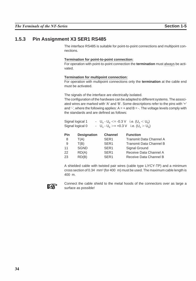
1.5.3 Pin Assignment X3 SER1 RS485The interface RS485 is suitable for point-to-point connections and multipoint con-nections.
Termination for point-to-point connection:For operation with point-to-point connection the termination must always be acti-vated.
Termination for multipoint connection:For operation with multipoint connections only the termination at the cable endmust be activated.
The signals of the interface are electrically isolated.The configuration of the hardware can be adapted to different systems. The associ-ated wires are marked with ‘A’ and ‘B’. Some descriptions refer to the pins with ‘+’and ‘-’, where the following applies: A = + and B = -. The voltage levels comply withthe standards and are defined as follows:
Signal logical 1 - UA - UB ,= -0.3 V i.e. (UA , UB)Signal logical 0 - UA - UB .= +0.3 V i.e. (UA . UB)
Pin Designation Channel Function8 T(A) SER1 Transmit Data Channel A9 T(B) SER1 Transmit Data Channel B
11 SGND SER1 Signal Ground22 RD(A) SER1 Receive Data Channel A23 RD(B) SER1 Receive Data Channel B
A shielded cable with twisted pair wires (cable type LiYCY-TP) and a minimumcross section of 0.34 mm2 (for 400 m) must be used. The maximum cable length is400 m.
Connect the cable shield to the metal hoods of the connectors over as large asurface as possible!
35
The Terminals of the NT-Series Section 1-5
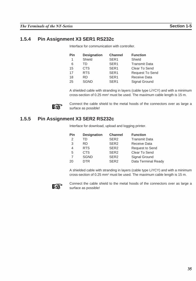
1.5.4 Pin Assignment X3 SER1 RS232cInterface for communication with controller.
Pin Designation Channel Function1 Shield SER1 Shield6 TD SER1 Transmit Data
15 CTS SER1 Clear To Send17 RTS SER1 Request To Send18 RD SER1 Receive Data25 SGND SER1 Signal Ground
A shielded cable with stranding in layers (cable type LiYCY) and with a minimumcross-section of 0.25 mm2 must be used. The maximum cable length is 15 m.
Connect the cable shield to the metal hoods of the connectors over as large asurface as possible!
1.5.5 Pin Assignment X3 SER2 RS232cInterface for download, upload and logging printer.
Pin Designation Channel Function2 TD SER2 Transmit Data3 RD SER2 Receive Data4 RTS SER2 Request to Send5 CTS SER2 Clear To Send7 SGND SER2 Signal Ground
20 DTR SER2 Data Terminal Ready
A shielded cable with stranding in layers (cable type LiYCY) and with a minimumcross-section of 0.25 mm2 must be used. The maximum cable length is 15 m.
Connect the cable shield to the metal hoods of the connectors over as large asurface as possible!
36
The Terminals of the NT-Series Section 1-5
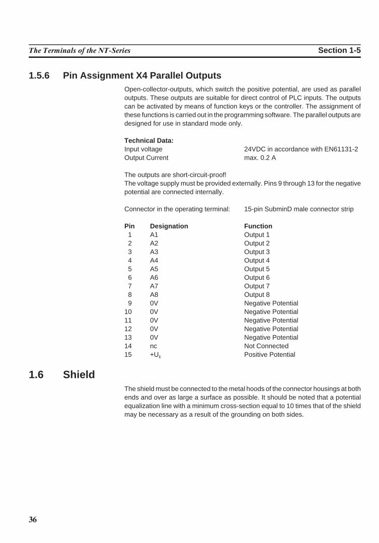
1.5.6 Pin Assignment X4 Parallel OutputsOpen-collector-outputs, which switch the positive potential, are used as paralleloutputs. These outputs are suitable for direct control of PLC inputs. The outputscan be activated by means of function keys or the controller. The assignment ofthese functions is carried out in the programming software. The parallel outputs aredesigned for use in standard mode only.
Technical Data:Input voltage 24VDC in accordance with EN61131-2Output Current max. 0.2 A
The outputs are short-circuit-proof!The voltage supply must be provided externally. Pins 9 through 13 for the negativepotential are connected internally.
Connector in the operating terminal: 15-pin SubminD male connector strip
Pin Designation Function1 A1 Output 12 A2 Output 23 A3 Output 34 A4 Output 45 A5 Output 56 A6 Output 67 A7 Output 78 A8 Output 89 0V Negative Potential
10 0V Negative Potential11 0V Negative Potential12 0V Negative Potential13 0V Negative Potential14 nc Not Connected15 +UE Positive Potential
1.6 ShieldThe shield must be connected to the metal hoods of the connector housings at bothends and over as large a surface as possible. It should be noted that a potentialequalization line with a minimum cross-section equal to 10 times that of the shieldmay be necessary as a result of the grounding on both sides.
37
The Terminals of the NT-Series Section 1-7
1.7 DisplayThe displays of the operating terminals either consist of backlight LCD modules ofdifferent sizes and different amounts of functions.All displays have an optimum viewing angle of approximately 90!.Also all displays are capable of displaying the enhanced ASCII character set (semigraphics).
The contrast of the display is stabilized over the full temperature range.The default contrast can be adjusted at operating time by means of a system vari-able.
If the display is damaged, do not swallow or breathe in the liquids or gases beingemitted and avoid direct contact with skin.Danger of Poisoning! Could Result in Burns!
1.7.1 NT4S-SF121B-E, NT4S-SF122B-E, NT4S-SF123B-EOverview of the technical data:
Type : LCD-ModuleGraphics Capability : Semi Graphics CapabilityBacklight : LED-BacklightBackground Colour : Yellow-green
Lines (Font Normal) : 4Characters/Line (Font Normal) : 20Character Matrix : 5 x 7 Dots + CursorCharacter Height (Font Normal) : 4.3 mmVisible Display Size : 74.0 mm x 23.0 mm
1.7.2 NT15S-SF121B-EOverview of the technical data:
Type : LCD-ModuleResolution : 240 x 64 DotsGraphics Capability : Full Graphics CapabilityBacklight : LED-BacklightBackground Colour : Yellow-green
Lines (Font Normal) : 8Characters/Line (Font Normal) : 40Character Matrix (Font Normal) : 6 x 8 DotsCharacter Matrix (Font Zoom) : 12 x 16 Dots
Dot Colour : BlackDot Size : 0.49 mm x 0.49 mmDot Gap Size : 0.04 mm
Visible Display Size : 134.0 mm x 40.4 mm
38
The Terminals of the NT-Series Section 1-7
1.7.3 NT18S-SF121B-EOverview of the technical data:
Type : LCD-ModuleResolution: 240 x 128 DotsGraphics Capability: Full Graphics CapabilityBacklight : LED-BacklightBackground Colour : White
Lines (Font Normal) : 16Characters/Line (Font Normal) : 40Character Matrix (Font Normal) : 6 x 8 DotsCharacter Matrix (Font Zoom) : 12 x 16 Dots
Dot Colour : BlackDot Size : 0.49 mm x 0.49 mmDot Gap Size : 0.04 mm
Visible Display Size : 131.0 mm x 72.0 mm
1.7.4 Contrast SettingThe contrast for the display can be adjusted by means of the software. This re-quires the system variable LCDContrast to be set up in an I/O mask of the applica-tion. The value can then be modified using any editor that can handle integer num-bers.The limit values for the contrast must be set to
Lower level: -25Upper level: +70
If this variable is not defined in the menus or the value is out of the range of values,the default setting (value 25) will be loaded when the system is initialized.The system variable can be stated in any I/O-mask of the application!
1.7.5 Default Contrast SettingIf the contrast of the display should be such that the masks are no longer legible, thedefault contrast setting can be restored using the user mode switch.
Position of the switch to restore the contrast:
S1 ONS2 OFFS3 OFFS4 ON
This switch position coincides with ‘activating download by hardware’. The contrastwill be reset before the warning is displayed. The warning will be displayed in alegible manner. Upon display of this warning, switch off the terminal, set the switch4 to the OFF-position and switch the terminal on again. The application descriptionis not lost.

39
The Terminals of the NT-Series Section 1-7
1.7.6 Character AttributesThe characters of the fonts Normal and Zoom can be displayed with differentattributes.
Operating Terminal Normal Flashing Underlined Inverse
NT4S-SF121B-E Yes Yes No No
NT4S-SF122B-E Yes Yes No No
NT4S-SF123B-E Yes Yes No No
NT15S-SF121B-E Yes Yes Yes Yes
NT18S-SF121B-E Yes Yes Yes Yes
1.7.6.1 Font Normal
1.7.6.2 Font Zoom
40
The Terminals of the NT-Series Section 1-7
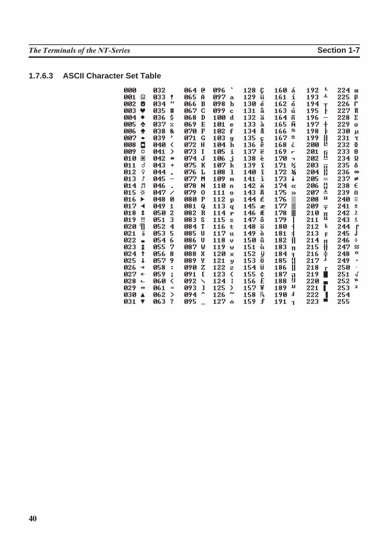
1.7.6.3 ASCII Character Set Table
41
The Terminals of the NT-Series Section 1-8
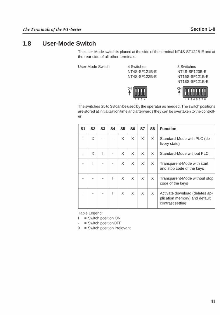
1.8 User-Mode SwitchThe user-Mode switch is placed at the side of the terminal NT4S-SF122B-E and atthe rear side of all other terminals.
User-Mode Switch 4 Switches 8 SwitchesNT4S-SF121B-E NT4S-SF123B-ENT4S-SF122B-E NT15S-SF121B-E
NT18S-SF121B-E
The switches S5 to S8 can be used by the operator as needed. The switch positionsare stored at initialization time and afterwards they can be overtaken to the controll-er.
S1 S2 S3 S4 S5 S6 S7 S8 Function
I X - - X X X X Standard-Mode with PLC (de-livery state)
I X I - X X X X Standard-Mode without PLC
- I - - X X X X Transparent-Mode with startand stop code of the keys
- - - I X X X X Transparent-Mode without stopcode of the keys
I - - I X X X X Activate download (deletes ap-plication memory) and defaultcontrast setting
Table Legend:I = Switch position ON- = Switch positionOFFX = Switch position irrelevant
42
The Terminals of the NT-Series Section 1-9
1.9 BatteryA built-in lithium battery buffers the data in the RAM memory and also supplies thereal-time clock with power. The discharge degree of the battery is monitored con-stantly to prevent any loss of data.The battery provides a minimum life of 5 years, even under unfavourable operatingconditions.If the battery is drained the system message ‘change battery’ is generated. A new battery is supported by OMRON EUROPE.
Replacing the battery:The battery can be replaced while the operating voltage is connected to ensure thatthe message data and time setting are not lost. Mind the safety instructions!
- Remove the mounting bolts of the 25-pin interface connector- Remove the fastening screws of the enclosure and remove the enclosure - Replace the cable fastener, which is used to fasten the battery- Plug off the cable of the battery and replace the discharged battery- Plug on the cable of the new battery- Fasten the new battery on the plastic holder on the printed circuit board
OBSERVE THE CORRECT POLARITY OF (−) AND (+)- Place the enclosure on the rear side of the terminal- At first fasten the bolts of the interface connector and at last fasten the screws of
the enclosure properly
Changing the battery may only be performed by qualified and authorized person-nel!
Sewage and refuse disposal:Dispose only drained batteries into the collection box of the community or of thelocal dealer. The battery is stated as drained when the message ‘change battery’appears on the display of the terminal.
To prevent short circuitry in the collection boxes insulate the poles of each batterywith insulation tape or put each single battery into a plastic bag.
Do not put lithium batteries in fire or heat them above 100 !C and do not rechargethem. Danger of Explosion!
Do not open lithium batteries. Danger of Poisoning!
Hazardous voltages can exist inside electrical installations that can pose a dangerto humans. Coming in contact with live parts may result in electric shock!
Electrostatic discharges can damage electronic components! ESD protective mea-sures must be observed!

43
The Terminals of the NT-Series Section 1-11
1.10 FuseA semiconductor fuse is used to prevent damage to the operating terminal. Oncethe fuse has been activated, the device must be disconnected from the supplyvoltage to allow the semiconductor fuse to regenerate. With an ambient tempera-ture of 20 !C, the regeneration takes about 20 seconds. The higher the ambienttemperature, the longer the regeneration period.The semiconductor fuse is not designed to be replaced.
Hazardous voltages can exist inside electrical installations that can pose a dangerto humans. Coming in contact with live parts may result in electric shock!
Electrostatic discharges can damage electronic components! ESD protective mea-sures must be observed!
1.11 Application MemoryA 256 kByte flash memory is used as an application memory for each operatingterminal . This memory area is available to store the user application, the loadableprotocol driver, the fonts and the recipe data. The advantage of the flash memory isthat programming and deleting processes can be carried out directly in the termi-nal.
Changing the application memory may only be performed by qualified and autho-rized personnel!
Hazardous voltages can exist inside electrical installations that can pose a dangerto humans. Coming in contact with live parts may result in electric shock!
Electrostatic discharges can damage electronic components! ESD protective mea-sures must be observed!


45
SECTION 2Technical Data
This section lists all the electrical and mechanical specifications of the terminals.
2.1 NT4S-SF121B-E . . . . . . . . . . . . . . . . . . . . . . . . . . . . . . . . . . . . . . . . . . . . . . . . . . . . . . . . . . . . . . . . . . . . . . . . . . . . 472.2 NT4S-SF122B-E . . . . . . . . . . . . . . . . . . . . . . . . . . . . . . . . . . . . . . . . . . . . . . . . . . . . . . . . . . . . . . . . . . . . . . . . . . . . 482.3 NT4S-SF123B-E . . . . . . . . . . . . . . . . . . . . . . . . . . . . . . . . . . . . . . . . . . . . . . . . . . . . . . . . . . . . . . . . . . . . . . . . . . . . 502.4 NT15S-SF121B-E . . . . . . . . . . . . . . . . . . . . . . . . . . . . . . . . . . . . . . . . . . . . . . . . . . . . . . . . . . . . . . . . . . . . . . . . . . . 512.5 NT18S-SF121B-E . . . . . . . . . . . . . . . . . . . . . . . . . . . . . . . . . . . . . . . . . . . . . . . . . . . . . . . . . . . . . . . . . . . . . . . . . . . 53

46
47
Technical Data Section 2-1
2 Technical Data
2.1 NT4S-SF121B-EKeyboard a Total of 11 Keys, Mechanical with Tactile Feedback
Divided into2 Control Keys4 Function Keys with LEDs and Slide-in Identification Strips1 Special Key without LED2 Special Keys with LEDs2 Editing Keys
Display Backlit LCD Module, 4 Lines with 20 Characters Each,Display Area 23 × 74 mm (H × W)with Glare Suppression for Increased Contrast
Interface X3 Variable Baud Rates and Data Formats600 to 19200 BdSER1 RS485, Electrically Isolated CommunicationSER1 TTY / 20 mA, Electrically Isolated CommunicationSER1 RS232c, Electrically Isolated CommunicationSER2 RS232c, Not Electrically Isolated Download/Logging Printer
Central Unit Z80-CPU, 10 MHz, Watchdog Timer, Real-Time Clock, Programmable InterfaceParameters, Temperature Compensation of the Display, Adjustment of Contrast,Battery Monitoring, User Mode Switch
Memory 256 Kbyte Flash Memory, Application Memory256 kByte Flash Memory, Firmware128 Kbyte stat. CMOS-RAM, Battery-Backed
Fuse Semiconductor Fuse
Connection System Plug-in Type, via SubminD Female Connector Strip
Supply Voltage 24 V Direct Voltage, Residual Ripple Max. 10%Minimum Voltage 19.2 VMaximum Voltage 30.2 VTyp. Power Consumption ,0.3 APeak Current (10 ms) ,0.5 A
Connected Load , 10 W
48
Technical Data Section 2-2
Noise Immunity EC Electromagnetic Compatibility Directive 89/336/EECEN 55011 Limit Class BEN 50081-1 Table A1EN 50082-2EN 61000-4-2EN 61000-4-3EN 61000-4-4EN 61000-4-5EN 61000-4-6
Environmental Test DIN40040 Operation StorageCode Letter - Temperature KW HUCode Letter - Humidity F F
Degrees of Protection DIN 40050 Mechanical Degrees of ProtectionFront: IP65Rear: IP20
Front Panel Aluminum, Black Anodized with Affixed Polyester Cover, Circumferential Polyu-rethane Foam Seal at Rear Side of Front Panel96.0 × 144.0 × 3.5 mm (H × W × D)
Panel Cutout 82 × 138 mm (H × W)
Mounting Depth 43 mm without Connector
Enclosure Zinc-Coated Steel Plate
Total Weight Approx. 400 g
2.2 NT4S-SF122B-EKeyboard a Total of 30 Keys, Membrane with Tactile Feedback
Divided into6 Control Keys6 Function Keys with LEDs and Slide-in Identification Strips2 Special Keys with LEDs3 Special Keys without LEDs
13 Editing Keys
Display Backlit LCD Module, 4 Lines with 20 Characters Each,Display Area 23 × 74 mm (H × W)with Glare Suppression for Increased Contrast
Interface X3 Variable Baud Rates and Data Formats600 to 19200 BdSER1 RS485, Electrically Isolated CommunicationSER1 TTY / 20 mA, Electrically Isolated CommunicationSER1 RS232c, Electrically Isolated CommunicationSER2 RS232c, Not Electrically Isolated Download/Logging Printer
49
Technical Data Section 2-2
Central Unit Z80-CPU, 10 MHz, Watchdog Timer, Real-Time Clock, Programmable InterfaceParameters, Temperature Compensation of the Display, Adjustment of Contrast,Battery Monitoring, User Mode Switch
Memory 256 Kbyte Flash Memory, Application Memory256 kByte Flash Memory, Firmware128 Kbyte stat. CMOS-RAM, Battery-Backed
Fuse Semiconductor Fuse
Connection System Plug-in Type, via SubminD Female Connector Strip
Supply Voltage 24 V Direct Voltage, Residual Ripple Max. 10%Minimum Voltage 19.2 VMaximum Voltage 30.2 VTyp. Power Consumption ,0.3 APeak Current (10 ms) ,0.5 A
Connected Load , 10 W
Noise Immunity EC Electromagnetic Compatibility Directive 89/336/EECEN 55011 Limit Class BEN 50081-1 Table A1EN 50082-2EN 61000-4-2EN 61000-4-3EN 61000-4-4EN 61000-4-5EN 61000-4-6
Environmental Test DIN40040 Operation StorageCode Letter - Temperature KW HUCode Letter - Humidity F F
Degrees of Protection DIN 40050 Mechanical Degrees of ProtectionFront: IP65Rear: IP20
Front Panel Aluminum, Black Anodized with Affixed Polyester Cover, Circumferential RubberSealing around rear of front panel168.0 × 120.0 × 4.0 mm (H × W × D)
Panel Cutout 160 × 112 mm (H × W)
Mounting Depth 40 mm without Connector
Enclosure Zinc-Coated Steel Plate
Total Weight 500 g
50
Technical Data Section 2-3
2.3 NT4S-SF123B-EKeyboard a Total of 30 Keys, Mechanical with Tactile Feedback
Divided into5 Control Keys8 Function Keys with LEDs and Slide-in Identification Strips2 Special Key without LED2 Special Keys with LEDs
13 Editing Keys
Display Backlit LCD Module, 4 Lines with 20 Characters Each,Display Area 23 × 74 mm (H × W)with Glare Suppression for Increased Contrast
Interface X3 Variable Baud Rates and Data Formats600 to 19200 BdSER1 RS485, Electrically Isolated CommunicationSER1 TTY / 20 mA, Electrically Isolated CommunicationSER1 RS232c, Electrically Isolated CommunicationSER2 RS232c, Not Electrically Isolated Download/Logging Printer
Central Unit Z80-CPU, 10 MHz, Watchdog Timer, Real-Time Clock, Programmable InterfaceParameters, Temperature Compensation of the Display, Adjustment of Contrast,Battery Monitoring, User Mode Switch
Memory 256 Kbyte Flash Memory, Application Memory256 kByte Flash Memory, Firmware128 Kbyte stat. CMOS-RAM, Battery-Backed
Fuse Semiconductor Fuse
Connection System Plug-in Type, via SubminD Female Connector Strip
Supply Voltage 24 V Direct Voltage, Residual Ripple Max. 10%Minimum Voltage 19.2 VMaximum Voltage 30.2 VTyp. Power Consumption ,0.35 APeak Current (10 ms) ,0.5 A
Connected Load , 10 W
Noise Immunity EC Electromagnetic Compatibility Directive 89/336/EECEN 55011 Limit Class BEN 50081-1 Table A1EN 50082-2EN 61000-4-2EN 61000-4-3EN 61000-4-4EN 61000-4-5EN 61000-4-6
51
Technical Data Section 2-4
Environmental Test DIN40040 Operation StorageCode Letter - Temperature KW HUCode Letter - Humidity F F
Degrees of Protection DIN 40050 Mechanical Degrees of ProtectionFront: IP65Rear: IP20
Front Panel Aluminum, Black Anodized with Affixed Polyester Cover, Circumferential SealingAround Rear of Front Panel150.0 × 270.0 × 3.0 mm (H × W × D)
Panel Cutout 112 × 232 mm (H × W)
Mounting Depth 48 mm without Connector
Enclosure Zinc-Coated Steel Plate
Total Weight approx. 800 g
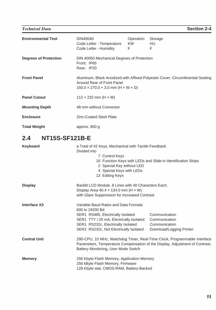
2.4 NT15S-SF121B-EKeyboard a Total of 42 Keys, Mechanical with Tactile Feedback
Divided into7 Control Keys
16 Function Keys with LEDs and Slide-in Identification Strips2 Special Key without LED4 Special Keys with LEDs
13 Editing Keys
Display Backlit LCD Module, 8 Lines with 40 Characters Each,Display Area 40.4 × 134.0 mm (H × W)with Glare Suppression for Increased Contrast
Interface X3 Variable Baud Rates and Data Formats600 to 19200 BdSER1 RS485, Electrically Isolated CommunicationSER1 TTY / 20 mA, Electrically Isolated CommunicationSER1 RS232c, Electrically Isolated CommunicationSER2 RS232c, Not Electrically Isolated Download/Logging Printer
Central Unit Z80-CPU, 10 MHz, Watchdog Timer, Real-Time Clock, Programmable InterfaceParameters, Temperature Compensation of the Display, Adjustment of Contrast,Battery Monitoring, User Mode Switch
Memory 256 Kbyte Flash Memory, Application Memory256 kByte Flash Memory, Firmware128 Kbyte stat. CMOS-RAM, Battery-Backed
52
Technical Data Section 2-4
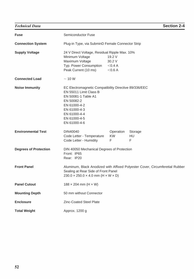
Fuse Semiconductor Fuse
Connection System Plug-in Type, via SubminD Female Connector Strip
Supply Voltage 24 V Direct Voltage, Residual Ripple Max. 10%Minimum Voltage 19.2 VMaximum Voltage 30.2 VTyp. Power Consumption ,0.4 APeak Current (10 ms) ,0.6 A
Connected Load , 10 W
Noise Immunity EC Electromagnetic Compatibility Directive 89/336/EECEN 55011 Limit Class BEN 50081-1 Table A1EN 50082-2EN 61000-4-2EN 61000-4-3EN 61000-4-4EN 61000-4-5EN 61000-4-6
Environmental Test DIN40040 Operation StorageCode Letter - Temperature KW HUCode Letter - Humidity F F
Degrees of Protection DIN 40050 Mechanical Degrees of ProtectionFront: IP65Rear: IP20
Front Panel Aluminum, Black Anodized with Affixed Polyester Cover, Circumferetial RubberSealing at Rear Side of Front Panel230.0 × 250.0 × 4.0 mm (H × W × D)
Panel Cutout 188 × 204 mm (H × W)
Mounting Depth 50 mm without Connector
Enclosure Zinc-Coated Steel Plate
Total Weight Approx. 1200 g
53
Technical Data Section 2-5
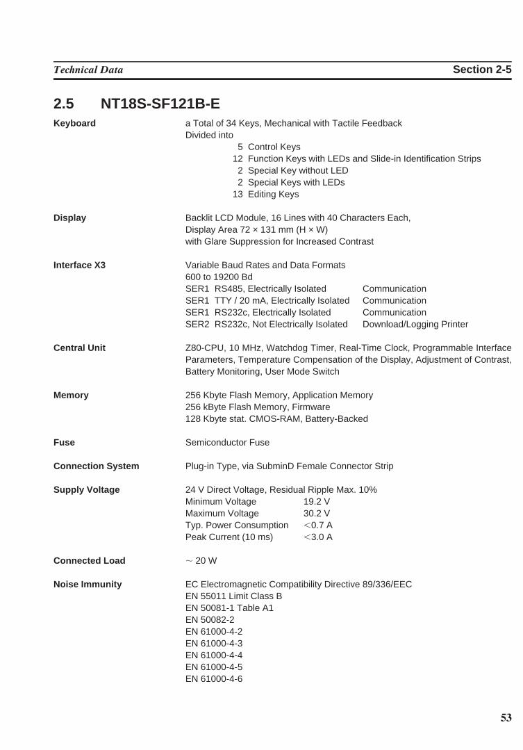
2.5 NT18S-SF121B-EKeyboard a Total of 34 Keys, Mechanical with Tactile Feedback
Divided into5 Control Keys
12 Function Keys with LEDs and Slide-in Identification Strips2 Special Key without LED2 Special Keys with LEDs
13 Editing Keys
Display Backlit LCD Module, 16 Lines with 40 Characters Each,Display Area 72 × 131 mm (H × W)with Glare Suppression for Increased Contrast
Interface X3 Variable Baud Rates and Data Formats600 to 19200 BdSER1 RS485, Electrically Isolated CommunicationSER1 TTY / 20 mA, Electrically Isolated CommunicationSER1 RS232c, Electrically Isolated CommunicationSER2 RS232c, Not Electrically Isolated Download/Logging Printer
Central Unit Z80-CPU, 10 MHz, Watchdog Timer, Real-Time Clock, Programmable InterfaceParameters, Temperature Compensation of the Display, Adjustment of Contrast,Battery Monitoring, User Mode Switch
Memory 256 Kbyte Flash Memory, Application Memory256 kByte Flash Memory, Firmware128 Kbyte stat. CMOS-RAM, Battery-Backed
Fuse Semiconductor Fuse
Connection System Plug-in Type, via SubminD Female Connector Strip
Supply Voltage 24 V Direct Voltage, Residual Ripple Max. 10%Minimum Voltage 19.2 VMaximum Voltage 30.2 VTyp. Power Consumption ,0.7 APeak Current (10 ms) ,3.0 A
Connected Load , 20 W
Noise Immunity EC Electromagnetic Compatibility Directive 89/336/EECEN 55011 Limit Class BEN 50081-1 Table A1EN 50082-2EN 61000-4-2EN 61000-4-3EN 61000-4-4EN 61000-4-5EN 61000-4-6
54
Technical Data Section 2-5
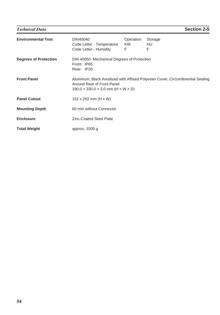
Environmental Test DIN40040 Operation StorageCode Letter - Temperature KW HUCode Letter - Humidity F F
Degrees of Protection DIN 40050 Mechanical Degrees of ProtectionFront: IP65Rear: IP20
Front Panel Aluminum, Black Anodized with Affixed Polyester Cover, Circumferential SealingAround Rear of Front Panel190.0 × 330.0 × 3.0 mm (H × W × D)
Panel Cutout 152 x 292 mm (H x W)
Mounting Depth 60 mm without Connector
Enclosure Zinc-Coated Steel Plate
Total Weight approx. 1500 g

55
SECTION 3Operating Modes
This section describes the two available operation modes, the standard mode and the transparant modeand indicates how to select the operation mode.
3.1 Setting the Operating Mode . . . . . . . . . . . . . . . . . . . . . . . . . . . . . . . . . . . . . . . . . . . . . . . . . . . . . . . . . . . . . . . . . 57

56
57
Operating Modes Section 3-1
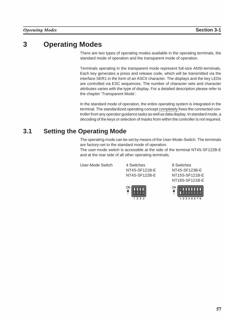
3 Operating ModesThere are two types of operating modes available in the operating terminals, thestandard mode of operation and the transparent mode of operation.
Terminals operating in the transparent mode represent full-size ANSI-terminals.Each key generates a press and release code, which will be transmitted via theinterface SER1 in the form of an ASCII character. The displays and the key LEDsare controlled via ESC sequences. The number of character sets and characterattributes varies with the type of display. For a detailed description please refer tothe chapter ‘Transparent Mode’.
In the standard mode of operation, the entire operating system is integrated in theterminal. The standardized operating concept completely frees the connected con-troller from any operator guidance tasks as well as data display. In standard mode, adecoding of the keys or selection of masks from within the controller is not required.
3.1 Setting the Operating ModeThe operating mode can be set by means of the User-Mode-Switch. The terminalsare factory-set to the standard mode of operation. The user-mode switch is accessible at the side of the terminal NT4S-SF122B-Eand at the rear side of all other operating terminals.
User-Mode Switch 4 Switches 8 SwitchesNT4S-SF121B-E NT4S-SF123B-ENT4S-SF122B-E NT15S-SF121B-E
NT18S-SF121B-E
58
Operating Modes Section 3-1
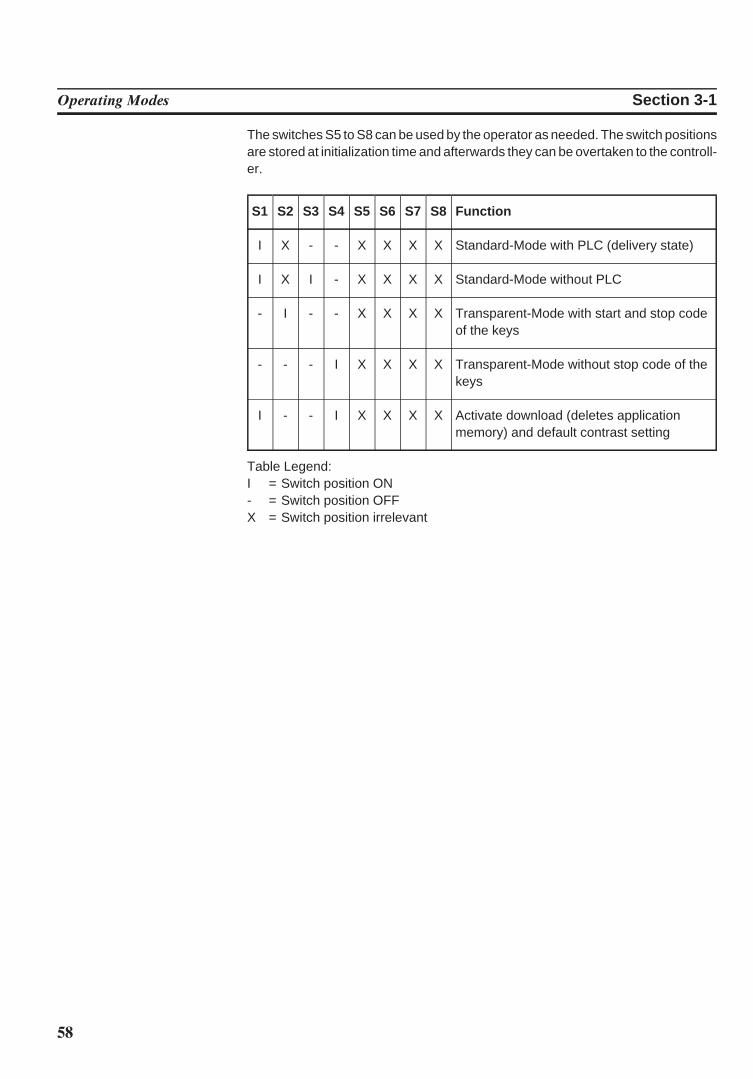
The switches S5 to S8 can be used by the operator as needed. The switch positionsare stored at initialization time and afterwards they can be overtaken to the controll-er.
S1 S2 S3 S4 S5 S6 S7 S8 Function
I X - - X X X X Standard-Mode with PLC (delivery state)
I X I - X X X X Standard-Mode without PLC
- I - - X X X X Transparent-Mode with start and stop codeof the keys
- - - I X X X X Transparent-Mode without stop code of thekeys
I - - I X X X X Activate download (deletes applicationmemory) and default contrast setting
Table Legend:I = Switch position ON- = Switch position OFFX = Switch position irrelevant
59
SECTION 4Standard Mode
This section describes the standard operation mode in detail. This section contains all detailed informa-tion to understand all features of the terminal in order to make a terminal application.
4.1 Setting the Operating Mode . . . . . . . . . . . . . . . . . . . . . . . . . . . . . . . . . . . . . . . . . . . . . . . . . . . . . . . . . . . . . . . . . 634.2 Startup Process. . . . . . . . . . . . . . . . . . . . . . . . . . . . . . . . . . . . . . . . . . . . . . . . . . . . . . . . . . . . . . . . . . . . . . . . . . . . . . 64
4.2.1 Startup Process without a Valid User Description . . . . . . . . . . . . . . . . . . . . . . . . . . . . . . . . . . . . . 654.3 Communication in the Standard Mode . . . . . . . . . . . . . . . . . . . . . . . . . . . . . . . . . . . . . . . . . . . . . . . . . . . . . . . 654.4 Operating Concept . . . . . . . . . . . . . . . . . . . . . . . . . . . . . . . . . . . . . . . . . . . . . . . . . . . . . . . . . . . . . . . . . . . . . . . . . . 65
4.4.1 Mask Structure . . . . . . . . . . . . . . . . . . . . . . . . . . . . . . . . . . . . . . . . . . . . . . . . . . . . . . . . . . . . . . . . . . . . . . 654.4.2 External Mask Selection . . . . . . . . . . . . . . . . . . . . . . . . . . . . . . . . . . . . . . . . . . . . . . . . . . . . . . . . . . . . . 664.4.3 Password Protection, Access Authorization . . . . . . . . . . . . . . . . . . . . . . . . . . . . . . . . . . . . . . . . . . . 66
4.4.3.1 Reactivating the Password Protection . . . . . . . . . . . . . . . . . . . . . . . . . . . . . . . . . . . . . . . . 694.4.3.2 Password Management. . . . . . . . . . . . . . . . . . . . . . . . . . . . . . . . . . . . . . . . . . . . . . . . . . . . . . 694.4.3.3 Password Mask and Password Functionality . . . . . . . . . . . . . . . . . . . . . . . . . . . . . . . . . . 69
4.5 Masks . . . . . . . . . . . . . . . . . . . . . . . . . . . . . . . . . . . . . . . . . . . . . . . . . . . . . . . . . . . . . . . . . . . . . . . . . . . . . . . . . . . . . . 704.5.1 Mask Parameters . . . . . . . . . . . . . . . . . . . . . . . . . . . . . . . . . . . . . . . . . . . . . . . . . . . . . . . . . . . . . . . . . . . . 704.5.2 System Masks . . . . . . . . . . . . . . . . . . . . . . . . . . . . . . . . . . . . . . . . . . . . . . . . . . . . . . . . . . . . . . . . . . . . . . . 70
4.5.2.1 Setup Mask. . . . . . . . . . . . . . . . . . . . . . . . . . . . . . . . . . . . . . . . . . . . . . . . . . . . . . . . . . . . . . . . . 714.5.2.1.1 Password Protection - Setup Mask . . . . . . . . . . . . . . . . . . . . . . . . . . . . . . . . 714.5.2.1.2 Function Without the Setup Mask . . . . . . . . . . . . . . . . . . . . . . . . . . . . . . . . 71
4.5.2.2 Start Mask. . . . . . . . . . . . . . . . . . . . . . . . . . . . . . . . . . . . . . . . . . . . . . . . . . . . . . . . . . . . . . . . . . 714.5.2.3 Password Mask . . . . . . . . . . . . . . . . . . . . . . . . . . . . . . . . . . . . . . . . . . . . . . . . . . . . . . . . . . . . . 724.5.2.4 I/O Mask . . . . . . . . . . . . . . . . . . . . . . . . . . . . . . . . . . . . . . . . . . . . . . . . . . . . . . . . . . . . . . . . . . . 72
4.6 Variables . . . . . . . . . . . . . . . . . . . . . . . . . . . . . . . . . . . . . . . . . . . . . . . . . . . . . . . . . . . . . . . . . . . . . . . . . . . . . . . . . . . 724.6.1 Output Variables . . . . . . . . . . . . . . . . . . . . . . . . . . . . . . . . . . . . . . . . . . . . . . . . . . . . . . . . . . . . . . . . . . . . 73
4.6.1.1 ‘Decimal Number’ Representation. . . . . . . . . . . . . . . . . . . . . . . . . . . . . . . . . . . . . . . . . . . 764.6.1.1.1 ‘Standard’ Variable Type . . . . . . . . . . . . . . . . . . . . . . . . . . . . . . . . . . . . . . . . 764.6.1.1.2 ‘Timer’ Variable Type . . . . . . . . . . . . . . . . . . . . . . . . . . . . . . . . . . . . . . . . . . . 764.6.1.1.3 ‘Counter’ Variable Type . . . . . . . . . . . . . . . . . . . . . . . . . . . . . . . . . . . . . . . . . 774.6.1.1.4 ‘BCD-Number’ Variable Type . . . . . . . . . . . . . . . . . . . . . . . . . . . . . . . . . . . 78
4.6.1.2 ‘Alphanumerical’ Representation . . . . . . . . . . . . . . . . . . . . . . . . . . . . . . . . . . . . . . . . . . . 784.6.1.3 ‘Selection Text’ Representation . . . . . . . . . . . . . . . . . . . . . . . . . . . . . . . . . . . . . . . . . . . . . 784.6.1.4 ‘Selection Image’ Representation . . . . . . . . . . . . . . . . . . . . . . . . . . . . . . . . . . . . . . . . . . . 794.6.1.5 ‘Floating Point Number’ Representation . . . . . . . . . . . . . . . . . . . . . . . . . . . . . . . . . . . . 804.6.1.6 ‘Hexadecimal Number’ Representation . . . . . . . . . . . . . . . . . . . . . . . . . . . . . . . . . . . . . 804.6.1.7 ‘Binary Number’ Representation . . . . . . . . . . . . . . . . . . . . . . . . . . . . . . . . . . . . . . . . . . . . 814.6.1.8 Bar Representation . . . . . . . . . . . . . . . . . . . . . . . . . . . . . . . . . . . . . . . . . . . . . . . . . . . . . . . . 814.6.1.9 Curve Representation (Trendline) . . . . . . . . . . . . . . . . . . . . . . . . . . . . . . . . . . . . . . . . . . . 82
4.6.2 Input Variables . . . . . . . . . . . . . . . . . . . . . . . . . . . . . . . . . . . . . . . . . . . . . . . . . . . . . . . . . . . . . . . . . . . . . . 834.6.3 System Variables . . . . . . . . . . . . . . . . . . . . . . . . . . . . . . . . . . . . . . . . . . . . . . . . . . . . . . . . . . . . . . . . . . . . 85
4.6.3.1 Basic Functions . . . . . . . . . . . . . . . . . . . . . . . . . . . . . . . . . . . . . . . . . . . . . . . . . . . . . . . . . . . . . 854.6.3.2 Communication SER1 . . . . . . . . . . . . . . . . . . . . . . . . . . . . . . . . . . . . . . . . . . . . . . . . . . . . . . 874.6.3.3 Error Statistics SER1 . . . . . . . . . . . . . . . . . . . . . . . . . . . . . . . . . . . . . . . . . . . . . . . . . . . . . . . 894.6.3.4 Communication SER2 . . . . . . . . . . . . . . . . . . . . . . . . . . . . . . . . . . . . . . . . . . . . . . . . . . . . . . 904.6.3.5 Real-Time Clock . . . . . . . . . . . . . . . . . . . . . . . . . . . . . . . . . . . . . . . . . . . . . . . . . . . . . . . . . . . 924.6.3.6 Serial Message System . . . . . . . . . . . . . . . . . . . . . . . . . . . . . . . . . . . . . . . . . . . . . . . . . . . . . . 93
60
4.6.3.7 Parallel Message System . . . . . . . . . . . . . . . . . . . . . . . . . . . . . . . . . . . . . . . . . . . . . . . . . . . . 964.6.3.8 Printer Control . . . . . . . . . . . . . . . . . . . . . . . . . . . . . . . . . . . . . . . . . . . . . . . . . . . . . . . . . . . . . 984.6.3.9 Menu Control / Keys. . . . . . . . . . . . . . . . . . . . . . . . . . . . . . . . . . . . . . . . . . . . . . . . . . . . . . . . 994.6.3.10 Password . . . . . . . . . . . . . . . . . . . . . . . . . . . . . . . . . . . . . . . . . . . . . . . . . . . . . . . . . . . . . . . . . . . 1064.6.3.11 Recipes . . . . . . . . . . . . . . . . . . . . . . . . . . . . . . . . . . . . . . . . . . . . . . . . . . . . . . . . . . . . . . . . . . . . 1074.6.3.12 Running Time Meter. . . . . . . . . . . . . . . . . . . . . . . . . . . . . . . . . . . . . . . . . . . . . . . . . . . . . . . . 1124.6.3.13 Loop-Through Operation . . . . . . . . . . . . . . . . . . . . . . . . . . . . . . . . . . . . . . . . . . . . . . . . . . . 1124.6.3.14 Loadable Font . . . . . . . . . . . . . . . . . . . . . . . . . . . . . . . . . . . . . . . . . . . . . . . . . . . . . . . . . . . . . . 1134.6.3.15 Maintenance. . . . . . . . . . . . . . . . . . . . . . . . . . . . . . . . . . . . . . . . . . . . . . . . . . . . . . . . . . . . . . . . 1134.6.3.16 Editors . . . . . . . . . . . . . . . . . . . . . . . . . . . . . . . . . . . . . . . . . . . . . . . . . . . . . . . . . . . . . . . . . . . . . 1144.6.3.17 Help . . . . . . . . . . . . . . . . . . . . . . . . . . . . . . . . . . . . . . . . . . . . . . . . . . . . . . . . . . . . . . . . . . . . . . . 114
4.6.4 Editors . . . . . . . . . . . . . . . . . . . . . . . . . . . . . . . . . . . . . . . . . . . . . . . . . . . . . . . . . . . . . . . . . . . . . . . . . . . . . . 1154.6.4.1 Decimal Number Editor . . . . . . . . . . . . . . . . . . . . . . . . . . . . . . . . . . . . . . . . . . . . . . . . . . . . 1164.6.4.2 Floating Point Number Editor . . . . . . . . . . . . . . . . . . . . . . . . . . . . . . . . . . . . . . . . . . . . . . . 1174.6.4.3 Hexadecimal Editor. . . . . . . . . . . . . . . . . . . . . . . . . . . . . . . . . . . . . . . . . . . . . . . . . . . . . . . . . 1184.6.4.4 Alphanumerical Editor. . . . . . . . . . . . . . . . . . . . . . . . . . . . . . . . . . . . . . . . . . . . . . . . . . . . . . 1184.6.4.5 Selection Text Editor . . . . . . . . . . . . . . . . . . . . . . . . . . . . . . . . . . . . . . . . . . . . . . . . . . . . . . . 1194.6.4.6 Selection Image Editor. . . . . . . . . . . . . . . . . . . . . . . . . . . . . . . . . . . . . . . . . . . . . . . . . . . . . . 1194.6.4.7 Table Editor. . . . . . . . . . . . . . . . . . . . . . . . . . . . . . . . . . . . . . . . . . . . . . . . . . . . . . . . . . . . . . . . 119
4.6.5 External Data Release . . . . . . . . . . . . . . . . . . . . . . . . . . . . . . . . . . . . . . . . . . . . . . . . . . . . . . . . . . . . . . . 1214.6.6 PLC-Handshake . . . . . . . . . . . . . . . . . . . . . . . . . . . . . . . . . . . . . . . . . . . . . . . . . . . . . . . . . . . . . . . . . . . . . 1234.6.7 Refreshing One-Time Output Data . . . . . . . . . . . . . . . . . . . . . . . . . . . . . . . . . . . . . . . . . . . . . . . . . . . 1234.6.8 Modified Data . . . . . . . . . . . . . . . . . . . . . . . . . . . . . . . . . . . . . . . . . . . . . . . . . . . . . . . . . . . . . . . . . . . . . . . 124
4.6.8.1 Input Plausibility Check. . . . . . . . . . . . . . . . . . . . . . . . . . . . . . . . . . . . . . . . . . . . . . . . . . . . . 1244.7 Graphics . . . . . . . . . . . . . . . . . . . . . . . . . . . . . . . . . . . . . . . . . . . . . . . . . . . . . . . . . . . . . . . . . . . . . . . . . . . . . . . . . . . . 124
4.7.1 Images . . . . . . . . . . . . . . . . . . . . . . . . . . . . . . . . . . . . . . . . . . . . . . . . . . . . . . . . . . . . . . . . . . . . . . . . . . . . . . 1244.7.2 Graphics on Operating Terminals. . . . . . . . . . . . . . . . . . . . . . . . . . . . . . . . . . . . . . . . . . . . . . . . . . . . . 125
4.7.2.1 Background Images . . . . . . . . . . . . . . . . . . . . . . . . . . . . . . . . . . . . . . . . . . . . . . . . . . . . . . . . . 1254.8 Recipes . . . . . . . . . . . . . . . . . . . . . . . . . . . . . . . . . . . . . . . . . . . . . . . . . . . . . . . . . . . . . . . . . . . . . . . . . . . . . . . . . . . . . 126
4.8.1 Structure of a Recipe . . . . . . . . . . . . . . . . . . . . . . . . . . . . . . . . . . . . . . . . . . . . . . . . . . . . . . . . . . . . . . . . 1274.8.2 Processing Recipes and Data Sets. . . . . . . . . . . . . . . . . . . . . . . . . . . . . . . . . . . . . . . . . . . . . . . . . . . . . 127
4.8.2.1 Selecting a Recipe . . . . . . . . . . . . . . . . . . . . . . . . . . . . . . . . . . . . . . . . . . . . . . . . . . . . . . . . . . 1284.8.2.2 Selecting a Data Set. . . . . . . . . . . . . . . . . . . . . . . . . . . . . . . . . . . . . . . . . . . . . . . . . . . . . . . . . 1284.8.2.3 Copying a Data Set . . . . . . . . . . . . . . . . . . . . . . . . . . . . . . . . . . . . . . . . . . . . . . . . . . . . . . . . . 1284.8.2.4 Deleting a Data Set . . . . . . . . . . . . . . . . . . . . . . . . . . . . . . . . . . . . . . . . . . . . . . . . . . . . . . . . . 1294.8.2.5 Modifying a Data Set . . . . . . . . . . . . . . . . . . . . . . . . . . . . . . . . . . . . . . . . . . . . . . . . . . . . . . . 129
4.8.3 Data Set Transfer to / from a Controller . . . . . . . . . . . . . . . . . . . . . . . . . . . . . . . . . . . . . . . . . . . . . . 1294.8.3.1 Transfer to a Controller . . . . . . . . . . . . . . . . . . . . . . . . . . . . . . . . . . . . . . . . . . . . . . . . . . . . . 1294.8.3.2 Transfer from a Controller . . . . . . . . . . . . . . . . . . . . . . . . . . . . . . . . . . . . . . . . . . . . . . . . . . 131
4.8.4 Transferring Data Sets to / from a PC. . . . . . . . . . . . . . . . . . . . . . . . . . . . . . . . . . . . . . . . . . . . . . . . . 1324.8.4.1 Transfer to a PC . . . . . . . . . . . . . . . . . . . . . . . . . . . . . . . . . . . . . . . . . . . . . . . . . . . . . . . . . . . . 1324.8.4.2 Transfer from a PC . . . . . . . . . . . . . . . . . . . . . . . . . . . . . . . . . . . . . . . . . . . . . . . . . . . . . . . . . 1334.8.4.3 Structure of a Data Set File . . . . . . . . . . . . . . . . . . . . . . . . . . . . . . . . . . . . . . . . . . . . . . . . . 133
4.8.5 Printing Data Sets . . . . . . . . . . . . . . . . . . . . . . . . . . . . . . . . . . . . . . . . . . . . . . . . . . . . . . . . . . . . . . . . . . . 1354.8.6 Memory Requirements for Storing Data Sets. . . . . . . . . . . . . . . . . . . . . . . . . . . . . . . . . . . . . . . . . . 136
4.9 Message System. . . . . . . . . . . . . . . . . . . . . . . . . . . . . . . . . . . . . . . . . . . . . . . . . . . . . . . . . . . . . . . . . . . . . . . . . . . . . 1364.9.1 Internal Messages. . . . . . . . . . . . . . . . . . . . . . . . . . . . . . . . . . . . . . . . . . . . . . . . . . . . . . . . . . . . . . . . . . . . 136
4.9.1.1 System Messages. . . . . . . . . . . . . . . . . . . . . . . . . . . . . . . . . . . . . . . . . . . . . . . . . . . . . . . . . . . . 1364.9.1.1.1 Suppressing the Display of System Messages . . . . . . . . . . . . . . . . . . . . . . 140
4.9.1.2 Error Messages . . . . . . . . . . . . . . . . . . . . . . . . . . . . . . . . . . . . . . . . . . . . . . . . . . . . . . . . . . . . . 140
61
4.9.2 External Messages . . . . . . . . . . . . . . . . . . . . . . . . . . . . . . . . . . . . . . . . . . . . . . . . . . . . . . . . . . . . . . . . . . . 1464.9.2.1 Structure of an External Message. . . . . . . . . . . . . . . . . . . . . . . . . . . . . . . . . . . . . . . . . . . . 146
4.9.2.1.1 Assigning Message Numbers. . . . . . . . . . . . . . . . . . . . . . . . . . . . . . . . . . . . . . 1464.9.2.1.2 Message Buffer Size. . . . . . . . . . . . . . . . . . . . . . . . . . . . . . . . . . . . . . . . . . . . . . 1474.9.2.1.3 Message Texts, Variables . . . . . . . . . . . . . . . . . . . . . . . . . . . . . . . . . . . . . . . . . 1474.9.2.1.4 Sorting Messages. . . . . . . . . . . . . . . . . . . . . . . . . . . . . . . . . . . . . . . . . . . . . . . . . 1484.9.2.1.5 Message Priority for Direct Display . . . . . . . . . . . . . . . . . . . . . . . . . . . . . . . 1484.9.2.1.6 Printing the Message Memory . . . . . . . . . . . . . . . . . . . . . . . . . . . . . . . . . . . . 148
4.9.2.2 Message Mask, Status Message Mask . . . . . . . . . . . . . . . . . . . . . . . . . . . . . . . . . . . . . . . . 1494.9.2.2.1 Direct Selection of the Message Mask. . . . . . . . . . . . . . . . . . . . . . . . . . . . . 1504.9.2.2.2 Output Formats for Messages. . . . . . . . . . . . . . . . . . . . . . . . . . . . . . . . . . . . . 1504.9.2.2.3 Zooming Messages . . . . . . . . . . . . . . . . . . . . . . . . . . . . . . . . . . . . . . . . . . . . . . . 1514.9.2.2.4 Acknowledging Messages. . . . . . . . . . . . . . . . . . . . . . . . . . . . . . . . . . . . . . . . . 151
4.9.2.3 Serial Message System . . . . . . . . . . . . . . . . . . . . . . . . . . . . . . . . . . . . . . . . . . . . . . . . . . . . . . 1514.9.2.3.1 Full-Page Message Output. . . . . . . . . . . . . . . . . . . . . . . . . . . . . . . . . . . . . . . . 1524.9.2.3.2 Messages Directly to a Logging Printer. . . . . . . . . . . . . . . . . . . . . . . . . . . . 1524.9.2.3.3 Erasing the Message Memory Externally . . . . . . . . . . . . . . . . . . . . . . . . . . 1524.9.2.3.4 Information about the Serial Message System . . . . . . . . . . . . . . . . . . . . . 153
4.9.2.4 Parallel Message System (Status Messages) . . . . . . . . . . . . . . . . . . . . . . . . . . . . . . . . . . 1544.9.2.4.1 Number of Bytes for Status Messages . . . . . . . . . . . . . . . . . . . . . . . . . . . . . 1544.9.2.4.2 Image of the Status Messages . . . . . . . . . . . . . . . . . . . . . . . . . . . . . . . . . . . . . 1544.9.2.4.3 Time-Controlled Transfer of the Status Message. . . . . . . . . . . . . . . . . . . 1554.9.2.4.4 Event-Controlled Transfer of the Status Message . . . . . . . . . . . . . . . . . . 155
4.10 Help System . . . . . . . . . . . . . . . . . . . . . . . . . . . . . . . . . . . . . . . . . . . . . . . . . . . . . . . . . . . . . . . . . . . . . . . . . . . . . . . . 1554.10.1 Default Help Text . . . . . . . . . . . . . . . . . . . . . . . . . . . . . . . . . . . . . . . . . . . . . . . . . . . . . . . . . . . . . . . . . . . 1554.10.2 Help Text For Masks . . . . . . . . . . . . . . . . . . . . . . . . . . . . . . . . . . . . . . . . . . . . . . . . . . . . . . . . . . . . . . . . 156
4.10.2.1 Help Text for the Message Mask . . . . . . . . . . . . . . . . . . . . . . . . . . . . . . . . . . . . . . . . . . . . 1564.10.3 Help Text For Variables . . . . . . . . . . . . . . . . . . . . . . . . . . . . . . . . . . . . . . . . . . . . . . . . . . . . . . . . . . . . . 156
4.11 Function Keys . . . . . . . . . . . . . . . . . . . . . . . . . . . . . . . . . . . . . . . . . . . . . . . . . . . . . . . . . . . . . . . . . . . . . . . . . . . . . . 1564.11.1 Direct Selector Keys . . . . . . . . . . . . . . . . . . . . . . . . . . . . . . . . . . . . . . . . . . . . . . . . . . . . . . . . . . . . . . . . . 1564.11.2 Function Keys of the Controller . . . . . . . . . . . . . . . . . . . . . . . . . . . . . . . . . . . . . . . . . . . . . . . . . . . . . . 1574.11.3 Soft Keys . . . . . . . . . . . . . . . . . . . . . . . . . . . . . . . . . . . . . . . . . . . . . . . . . . . . . . . . . . . . . . . . . . . . . . . . . . . . 157
4.11.3.1 Reaction Time of Function and Soft Keys . . . . . . . . . . . . . . . . . . . . . . . . . . . . . . . . . . . . 1584.11.3.2 Control Keys as Function Keys . . . . . . . . . . . . . . . . . . . . . . . . . . . . . . . . . . . . . . . . . . . . . . 158
4.11.4 Function Keys Controlling Parallel Outputs . . . . . . . . . . . . . . . . . . . . . . . . . . . . . . . . . . . . . . . . . . . 1584.11.5 Status LEDs in the Function Keys . . . . . . . . . . . . . . . . . . . . . . . . . . . . . . . . . . . . . . . . . . . . . . . . . . . . 158
4.12 System Parameters . . . . . . . . . . . . . . . . . . . . . . . . . . . . . . . . . . . . . . . . . . . . . . . . . . . . . . . . . . . . . . . . . . . . . . . . . . 1594.12.1 System Parameters: General Parameters . . . . . . . . . . . . . . . . . . . . . . . . . . . . . . . . . . . . . . . . . . . . . . 1594.12.2 System Parameters: Poll Area . . . . . . . . . . . . . . . . . . . . . . . . . . . . . . . . . . . . . . . . . . . . . . . . . . . . . . . . 1594.12.3 System Parameters: Terminal Clock . . . . . . . . . . . . . . . . . . . . . . . . . . . . . . . . . . . . . . . . . . . . . . . . . . 1604.12.4 System Parameters: Running Time Meter . . . . . . . . . . . . . . . . . . . . . . . . . . . . . . . . . . . . . . . . . . . . . 1604.12.5 System Parameters: Message System. . . . . . . . . . . . . . . . . . . . . . . . . . . . . . . . . . . . . . . . . . . . . . . . . . 1604.12.6 System Parameters: Variant Buffer . . . . . . . . . . . . . . . . . . . . . . . . . . . . . . . . . . . . . . . . . . . . . . . . . . . 1604.12.7 System Parameters: Password Management . . . . . . . . . . . . . . . . . . . . . . . . . . . . . . . . . . . . . . . . . . . 1604.12.8 System Parameters: Printer Interface . . . . . . . . . . . . . . . . . . . . . . . . . . . . . . . . . . . . . . . . . . . . . . . . . 1604.12.9 System Parameters: Gateway . . . . . . . . . . . . . . . . . . . . . . . . . . . . . . . . . . . . . . . . . . . . . . . . . . . . . . . . . 1614.12.10 System Parameters: Data Set Transfer . . . . . . . . . . . . . . . . . . . . . . . . . . . . . . . . . . . . . . . . . . . . . . . . 1614.12.11 System Parameters: Parallel Outputs. . . . . . . . . . . . . . . . . . . . . . . . . . . . . . . . . . . . . . . . . . . . . . . . . . 161
4.13 Version Number . . . . . . . . . . . . . . . . . . . . . . . . . . . . . . . . . . . . . . . . . . . . . . . . . . . . . . . . . . . . . . . . . . . . . . . . . . . . 1614.14 Running Time Meter . . . . . . . . . . . . . . . . . . . . . . . . . . . . . . . . . . . . . . . . . . . . . . . . . . . . . . . . . . . . . . . . . . . . . . . . 1614.15 Parallel Outputs. . . . . . . . . . . . . . . . . . . . . . . . . . . . . . . . . . . . . . . . . . . . . . . . . . . . . . . . . . . . . . . . . . . . . . . . . . . . . 1634.16 Screen Saver . . . . . . . . . . . . . . . . . . . . . . . . . . . . . . . . . . . . . . . . . . . . . . . . . . . . . . . . . . . . . . . . . . . . . . . . . . . . . . . . 163
62
4.17 Image of the Mask Number. . . . . . . . . . . . . . . . . . . . . . . . . . . . . . . . . . . . . . . . . . . . . . . . . . . . . . . . . . . . . . . . . . 1644.18 Image of the Mode Selector Switch . . . . . . . . . . . . . . . . . . . . . . . . . . . . . . . . . . . . . . . . . . . . . . . . . . . . . . . . . . 1644.19 Terminal Clock . . . . . . . . . . . . . . . . . . . . . . . . . . . . . . . . . . . . . . . . . . . . . . . . . . . . . . . . . . . . . . . . . . . . . . . . . . . . . 164
4.19.1 Image of Date and Time . . . . . . . . . . . . . . . . . . . . . . . . . . . . . . . . . . . . . . . . . . . . . . . . . . . . . . . . . . . . . 1654.20 Read Coordination Byte. . . . . . . . . . . . . . . . . . . . . . . . . . . . . . . . . . . . . . . . . . . . . . . . . . . . . . . . . . . . . . . . . . . . . 166
4.20.1 Editing Request Bit (Bit ‘EA’) . . . . . . . . . . . . . . . . . . . . . . . . . . . . . . . . . . . . . . . . . . . . . . . . . . . . . . . 1664.20.2 Editing Status Bit (Bit ‘EZ’). . . . . . . . . . . . . . . . . . . . . . . . . . . . . . . . . . . . . . . . . . . . . . . . . . . . . . . . . . 1664.20.3 Refresh Request Bit (Bit ‘RA’). . . . . . . . . . . . . . . . . . . . . . . . . . . . . . . . . . . . . . . . . . . . . . . . . . . . . . . 1674.20.4 Liveness Flag (Bit ‘LM’) . . . . . . . . . . . . . . . . . . . . . . . . . . . . . . . . . . . . . . . . . . . . . . . . . . . . . . . . . . . . . 1674.20.5 Data Set Download Active (Bit ‘DDA’) . . . . . . . . . . . . . . . . . . . . . . . . . . . . . . . . . . . . . . . . . . . . . . 167
4.21 Write Coordination Byte . . . . . . . . . . . . . . . . . . . . . . . . . . . . . . . . . . . . . . . . . . . . . . . . . . . . . . . . . . . . . . . . . . . . 1684.21.1 External Data Release (Bit ‘ED’). . . . . . . . . . . . . . . . . . . . . . . . . . . . . . . . . . . . . . . . . . . . . . . . . . . . . 1684.21.2 Refresh Acknowledgement (Bit ‘RQ’) . . . . . . . . . . . . . . . . . . . . . . . . . . . . . . . . . . . . . . . . . . . . . . . . 1684.21.3 Resetting the Password. . . . . . . . . . . . . . . . . . . . . . . . . . . . . . . . . . . . . . . . . . . . . . . . . . . . . . . . . . . . . . . 1684.21.4 Liveness Flag (Bit ‘LM’) . . . . . . . . . . . . . . . . . . . . . . . . . . . . . . . . . . . . . . . . . . . . . . . . . . . . . . . . . . . . . 1684.21.5 Data Set Download Release (Bit ‘DDF’). . . . . . . . . . . . . . . . . . . . . . . . . . . . . . . . . . . . . . . . . . . . . . 169
4.22 Cyclic Poll Area. . . . . . . . . . . . . . . . . . . . . . . . . . . . . . . . . . . . . . . . . . . . . . . . . . . . . . . . . . . . . . . . . . . . . . . . . . . . . 1694.22.1 Byte-Oriented . . . . . . . . . . . . . . . . . . . . . . . . . . . . . . . . . . . . . . . . . . . . . . . . . . . . . . . . . . . . . . . . . . . . . . . 1704.22.2 Word-Oriented . . . . . . . . . . . . . . . . . . . . . . . . . . . . . . . . . . . . . . . . . . . . . . . . . . . . . . . . . . . . . . . . . . . . . . 1714.22.3 Image of the LEDs . . . . . . . . . . . . . . . . . . . . . . . . . . . . . . . . . . . . . . . . . . . . . . . . . . . . . . . . . . . . . . . . . . 1724.22.4 Serial Message Channel . . . . . . . . . . . . . . . . . . . . . . . . . . . . . . . . . . . . . . . . . . . . . . . . . . . . . . . . . . . . . 1724.22.5 Polling Time. . . . . . . . . . . . . . . . . . . . . . . . . . . . . . . . . . . . . . . . . . . . . . . . . . . . . . . . . . . . . . . . . . . . . . . . . 1734.22.6 Size of the Poll Area . . . . . . . . . . . . . . . . . . . . . . . . . . . . . . . . . . . . . . . . . . . . . . . . . . . . . . . . . . . . . . . . . 173
4.23 Control Codes . . . . . . . . . . . . . . . . . . . . . . . . . . . . . . . . . . . . . . . . . . . . . . . . . . . . . . . . . . . . . . . . . . . . . . . . . . . . . . 1734.23.1 Triggering Data Set Printouts . . . . . . . . . . . . . . . . . . . . . . . . . . . . . . . . . . . . . . . . . . . . . . . . . . . . . . . . 1734.23.2 Setting the Clock in the Operating Terminal . . . . . . . . . . . . . . . . . . . . . . . . . . . . . . . . . . . . . . . . . . 1734.23.3 Transferring Data Sets from the Controller to the Terminal. . . . . . . . . . . . . . . . . . . . . . . . . . . . 1744.23.4 Transferring Data Sets from the Terminal to the Controller. . . . . . . . . . . . . . . . . . . . . . . . . . . . 1744.23.5 Transferring Data Sets from the Controller to the Terminal (Individually) . . . . . . . . . . . . . . 1744.23.6 Refreshing the Message System . . . . . . . . . . . . . . . . . . . . . . . . . . . . . . . . . . . . . . . . . . . . . . . . . . . . . . 175
4.24 Cyclic Variables . . . . . . . . . . . . . . . . . . . . . . . . . . . . . . . . . . . . . . . . . . . . . . . . . . . . . . . . . . . . . . . . . . . . . . . . . . . . . 1754.25 Interface Parameters . . . . . . . . . . . . . . . . . . . . . . . . . . . . . . . . . . . . . . . . . . . . . . . . . . . . . . . . . . . . . . . . . . . . . . . . 1754.26 Variable Definition. . . . . . . . . . . . . . . . . . . . . . . . . . . . . . . . . . . . . . . . . . . . . . . . . . . . . . . . . . . . . . . . . . . . . . . . . . 175
4.26.1 Variable List . . . . . . . . . . . . . . . . . . . . . . . . . . . . . . . . . . . . . . . . . . . . . . . . . . . . . . . . . . . . . . . . . . . . . . . . 1764.27 Application Programming . . . . . . . . . . . . . . . . . . . . . . . . . . . . . . . . . . . . . . . . . . . . . . . . . . . . . . . . . . . . . . . . . . . 176
4.27.1 Configuring the System . . . . . . . . . . . . . . . . . . . . . . . . . . . . . . . . . . . . . . . . . . . . . . . . . . . . . . . . . . . . . . 1774.27.2 Programming Systems. . . . . . . . . . . . . . . . . . . . . . . . . . . . . . . . . . . . . . . . . . . . . . . . . . . . . . . . . . . . . . . . 1784.27.3 Project Description . . . . . . . . . . . . . . . . . . . . . . . . . . . . . . . . . . . . . . . . . . . . . . . . . . . . . . . . . . . . . . . . . . 178
4.27.3.1 Multilingual Projects . . . . . . . . . . . . . . . . . . . . . . . . . . . . . . . . . . . . . . . . . . . . . . . . . . . . . . . . 1784.27.3.2 Variants of a Project . . . . . . . . . . . . . . . . . . . . . . . . . . . . . . . . . . . . . . . . . . . . . . . . . . . . . . . . 179
4.27.4 Project Documentation . . . . . . . . . . . . . . . . . . . . . . . . . . . . . . . . . . . . . . . . . . . . . . . . . . . . . . . . . . . . . . 1794.27.4.1 Creating Documentation . . . . . . . . . . . . . . . . . . . . . . . . . . . . . . . . . . . . . . . . . . . . . . . . . . . . 179
4.27.5 Project Back-up. . . . . . . . . . . . . . . . . . . . . . . . . . . . . . . . . . . . . . . . . . . . . . . . . . . . . . . . . . . . . . . . . . . . . . 1804.27.6 Optimizing the Transmission Rate . . . . . . . . . . . . . . . . . . . . . . . . . . . . . . . . . . . . . . . . . . . . . . . . . . . . 180
4.28 Downloading the User Description. . . . . . . . . . . . . . . . . . . . . . . . . . . . . . . . . . . . . . . . . . . . . . . . . . . . . . . . . . . 1804.28.1 Downloading with Windows. . . . . . . . . . . . . . . . . . . . . . . . . . . . . . . . . . . . . . . . . . . . . . . . . . . . . . . . . . 1824.28.2 Application Memory . . . . . . . . . . . . . . . . . . . . . . . . . . . . . . . . . . . . . . . . . . . . . . . . . . . . . . . . . . . . . . . . . 1824.28.3 Loading an Application . . . . . . . . . . . . . . . . . . . . . . . . . . . . . . . . . . . . . . . . . . . . . . . . . . . . . . . . . . . . . . 1824.28.4 Activating the Download Function using the Software . . . . . . . . . . . . . . . . . . . . . . . . . . . . . . . . . 1834.28.5 Activating the Download Function using the Hardware. . . . . . . . . . . . . . . . . . . . . . . . . . . . . . . . 1834.28.6 Automatic Download Function . . . . . . . . . . . . . . . . . . . . . . . . . . . . . . . . . . . . . . . . . . . . . . . . . . . . . . . 1844.28.7 Download Cable . . . . . . . . . . . . . . . . . . . . . . . . . . . . . . . . . . . . . . . . . . . . . . . . . . . . . . . . . . . . . . . . . . . . . 184
4.29 Simulation without the Controller. . . . . . . . . . . . . . . . . . . . . . . . . . . . . . . . . . . . . . . . . . . . . . . . . . . . . . . . . . . . 184
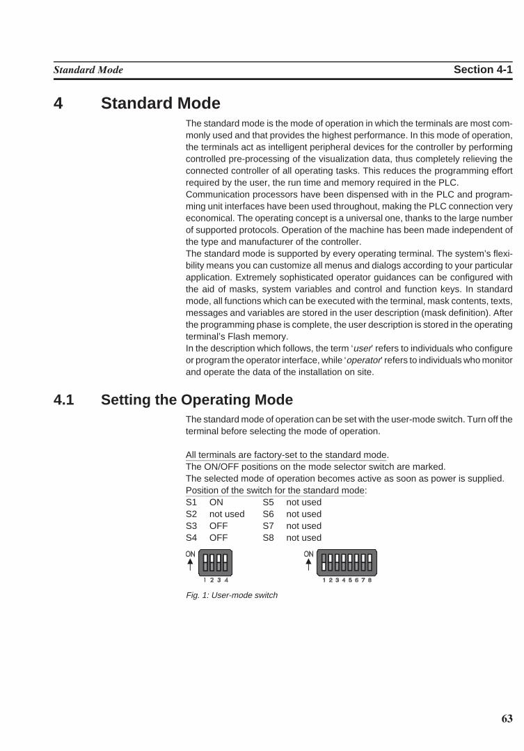
63
Standard Mode Section 4-1
4 Standard ModeThe standard mode is the mode of operation in which the terminals are most com-monly used and that provides the highest performance. In this mode of operation,the terminals act as intelligent peripheral devices for the controller by performingcontrolled pre-processing of the visualization data, thus completely relieving theconnected controller of all operating tasks. This reduces the programming effortrequired by the user, the run time and memory required in the PLC.Communication processors have been dispensed with in the PLC and program-ming unit interfaces have been used throughout, making the PLC connection veryeconomical. The operating concept is a universal one, thanks to the large numberof supported protocols. Operation of the machine has been made independent ofthe type and manufacturer of the controller. The standard mode is supported by every operating terminal. The system’s flexi-bility means you can customize all menus and dialogs according to your particularapplication. Extremely sophisticated operator guidances can be configured withthe aid of masks, system variables and control and function keys. In standardmode, all functions which can be executed with the terminal, mask contents, texts,messages and variables are stored in the user description (mask definition). Afterthe programming phase is complete, the user description is stored in the operatingterminal’s Flash memory.In the description which follows, the term ‘user’ refers to individuals who configureor program the operator interface, while ‘operator’ refers to individuals who monitorand operate the data of the installation on site.
4.1 Setting the Operating ModeThe standard mode of operation can be set with the user-mode switch. Turn off theterminal before selecting the mode of operation.
All terminals are factory-set to the standard mode.The ON/OFF positions on the mode selector switch are marked.The selected mode of operation becomes active as soon as power is supplied.Position of the switch for the standard mode:S1 ON S5 not usedS2 not used S6 not usedS3 OFF S7 not usedS4 OFF S8 not used
Fig. 1: User-mode switch
64
Standard Mode Section 4-2
4.2 Startup ProcessAll LEDs in the terminal are initially lit when the power is applied. A system-test isthen performed that includes testing and initialization of the modules in the oper-ating terminal. Various system and error messages may be output during this sys-tem-test. If the application memory contains a valid user description, the first mask,the Start-Mask, or the mask specified in the language parameters as the mask tobe used as the Start-Mask will appear on the display.This mask is displayed for 5 seconds (fixed time setting). This time can be used bythe operator to visually inspect the LEDs and the screen for proper functioning.After this time period, the Main Mask or the mask specified in the language para-meters as the Main Mask is displayed. This mask is the first mask of the operatorguidance.If the Enter key is pressed while the Startup Mask is displayed, the Setup Mask willappear on the display. This Setup Mask can be used to set the parameters for theinterface and the operating terminal.If the Enter key is pressed before the Startup Mask is displayed, an error messagewill be generated during the keyboard test.
. . . . . . .The self-test performed on the keyboard duringthe terminal start-up has detected that a key ispressed. Comply with the request and releasethe key. If this message is generated when nokey is pressed, this indicates a defective key-board. Generally, the message will disappearafter releasing the key/keys.
A longer delay may occur before the Startup Mask is displayed if the statisticsmemory contains a large number of messages from the serial message system.This time period (initialization period) is required to set up the structures for mes-sage management, which will then enable faster sorting of messages later. Duringthe initialization phase, the following message is displayed:
. . . . . . .When the terminal is switched on, the mes-sages that are present in the terminal are sort-ed. This process requires a certain length oftime (initialization time).
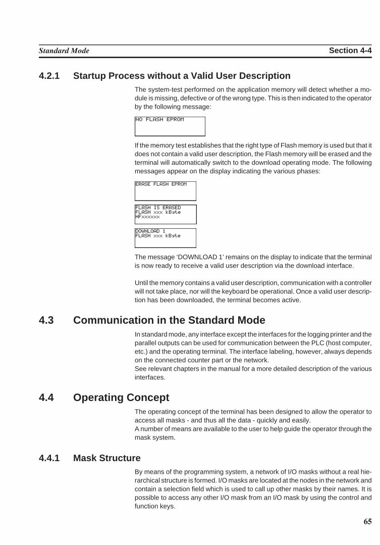
65
Standard Mode Section 4-4
4.2.1 Startup Process without a Valid User DescriptionThe system-test performed on the application memory will detect whether a mo-dule is missing, defective or of the wrong type. This is then indicated to the operatorby the following message:
If the memory test establishes that the right type of Flash memory is used but that itdoes not contain a valid user description, the Flash memory will be erased and theterminal will automatically switch to the download operating mode. The followingmessages appear on the display indicating the various phases:
The message ‘DOWNLOAD 1’ remains on the display to indicate that the terminalis now ready to receive a valid user description via the download interface.
Until the memory contains a valid user description, communication with a controllerwill not take place, nor will the keyboard be operational. Once a valid user descrip-tion has been downloaded, the terminal becomes active.
4.3 Communication in the Standard ModeIn standard mode, any interface except the interfaces for the logging printer and theparallel outputs can be used for communication between the PLC (host computer,etc.) and the operating terminal. The interface labeling, however, always dependson the connected counter part or the network. See relevant chapters in the manual for a more detailed description of the variousinterfaces.
4.4 Operating ConceptThe operating concept of the terminal has been designed to allow the operator toaccess all masks - and thus all the data - quickly and easily.A number of means are available to the user to help guide the operator through themask system.
4.4.1 Mask StructureBy means of the programming system, a network of I/O masks without a real hie-rarchical structure is formed. I/O masks are located at the nodes in the network andcontain a selection field which is used to call up other masks by their names. It ispossible to access any other I/O mask from an I/O mask by using the control andfunction keys.
66
Standard Mode Section 4-4
4.4.2 External Mask SelectionMask calls from the controller are handled in the same way as messages. Thisrequires simply that 8000H is added to the desired mask number prior to transfer.
When the same number is assigned to a mask and message, both the mask andthe message are called up during external mask selections.This effect can be used to provide help in a mask. Otherwise, ensure that differentnumbers are used for masks and messages.
A mask called up externally is considered selected once the desired mask numberappears in the variable ,Image of Mask Number.. The acknowledgement fromthe serial message channel is not a reliable confirmation of the mask output.
Example 1: Mask number and message number are not identicalA project comprises masks with numbers ranging from 100 to 200; the first mes-sage has the number 10.Mask 118 is to be called up by the controller.The following adding operation must be performed in the controller:
118 + 8000H = 76H + 8000H = 8076H.The value 8076H must be written to the address of the serial message channel.Only mask 118 is displayed.
Example 2: Mask number and message number are identicalA project comprises masks with numbers ranging from 1 to 100; the first messagehas the number 10.Mask 50 and serial message 50 are to be called up by the controller. The following adding operation must be performed in the controller:
50 + 8000H = 32H + 8000H = 8032H.The value 8032H must be written to the address of the serial message channel.Both the mask 50 is displayed and message 50 are written to the message buffer.
4.4.3 Password Protection, Access AuthorizationThe operating concept incorporates a password protection function. Passwordprotection prevents masks from being accessed and the data they contain frombeing altered without proper authorization. The protective function is available inevery operating terminal. It is obtained by assigning access levels to masks and byusing passwords.Unless otherwise specified by the programmer, the access levels of all masks auto-matically default to the lowest level (=0), i.e. no password is required to access allmasks with this access level. Two authorization levels, referred to as the edit level and the view level, are as-signed to every password.View level means that the next mask can be viewed after entering the password butthe values in it can also not be edited.Edit level means that the mask can be viewed after entering the password and thevalues in it can be edited.
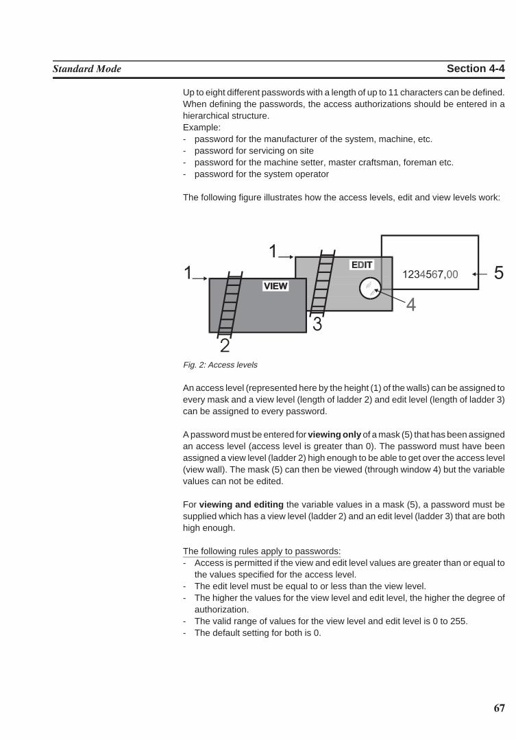
67
Standard Mode Section 4-4
Up to eight different passwords with a length of up to 11 characters can be defined.When defining the passwords, the access authorizations should be entered in ahierarchical structure.Example:- password for the manufacturer of the system, machine, etc.- password for servicing on site- password for the machine setter, master craftsman, foreman etc.- password for the system operator
The following figure illustrates how the access levels, edit and view levels work:
Fig. 2: Access levels
An access level (represented here by the height (1) of the walls) can be assigned toevery mask and a view level (length of ladder 2) and edit level (length of ladder 3)can be assigned to every password.
A password must be entered for viewing only of a mask (5) that has been assignedan access level (access level is greater than 0). The password must have beenassigned a view level (ladder 2) high enough to be able to get over the access level(view wall). The mask (5) can then be viewed (through window 4) but the variablevalues can not be edited.
For viewing and editing the variable values in a mask (5), a password must besupplied which has a view level (ladder 2) and an edit level (ladder 3) that are bothhigh enough.
The following rules apply to passwords:- Access is permitted if the view and edit level values are greater than or equal to
the values specified for the access level.- The edit level must be equal to or less than the view level.- The higher the values for the view level and edit level, the higher the degree of
authorization.- The valid range of values for the view level and edit level is 0 to 255.- The default setting for both is 0.
68
Standard Mode Section 4-4
The Data Release key will have no function if pressed with an insufficient edit level.The password can be entered in any I/O mask. Note that the Setup Mask is anexception. The system variable MskchgPasswd is designed to prompt for pass-word entry. If the Password Editor is selected in the programming system, pass-words will not appear as they are entered on the terminal. Instead the character ‘X’appears for every character that is entered.
Example:Enter PASSWORD: XXXXThis example illustrates hidden entry of a 4-digit number. If an invalid password isentered, the authorization levels will automatically reset to 0.It is recommended that at least one password - the master password - is pro-grammed with the highest authorization level. The first password entered in thepassword list via the programming system is the master password and as such hasa special function. The master password is unique in that it can not be changed onthe operating terminal. Furthermore, it can be used to reset all modified passwordsto the default values entered in the programming system.
Example:Mask 5 access level = 10Mask 6 access level = 20Mask 7 access level = 30Password 4712 Edit level = 15 View level = 25
Once the password ‘4712’ has been entered, the following accesses are permitted:- Mask 5 will be displayed, editing of values is authorized- Mask 6 will be displayed, editing of values is not authorized- Mask 7 will not be displayed, editing of values is not authorized
The access level for the Startup Mask is always 0.The Setup Mask is an exception with regards to the password and external datarelease functions. Since no communication is taking place when the Setup Mask isdisplayed, the external data release function is not applicable. To restrict access,passwords must be used. By defining the first editable variable in the Setup Maskas a Password Editor, all further variables can be protected against unauthorizedaccess. The view level does not apply when accessing the Setup Mask. Viewing isalways permitted if a value less than or equal to 254 is selected for the access levelof the Setup Mask.The edit level for all variables of the Setup Mask, with the exception of the Pass-word Editor, is the same as that defined as the access level.Access to the mask is always denied if an access level of 255 is defined for thesetup mask. This means that it will no longer be displayed during initialization of theterminal and can therefore not be selected. However, all terminal-specific param-eters can also be edited in any I/O mask. The new parameters become effective byrestarting the terminal or with the system variable Boot .
69
Standard Mode Section 4-4
4.4.3.1 Reactivating the Password Protection
The access authorization for a mask or variable is reset whenever- the operating terminal is switched off and turned back on- an incorrect password is entered- bit 2 in the ,Write Coordination Byte. is set - the system variable MskchgResPasswd is activated- the option Reset Password in the mask parameters of the password-protected
mask is selected.
4.4.3.2 Password Management
Passwords are stored in the operating terminal’s Flash memory. These are thedefault passwords that are used when the terminal is started up initially after adownload. At the same time, the passwords are stored in the operating terminal’sRAM.The passwords stored in the flash memory can be reactivated by writing to thesystem variable FlashPasswd .
Every password (except for the master password = first password in the list) can beedited from the terminal. For this process, the password to be edited is written to thesystem variable MskchgPasswd first. The new password is then written twice tothe system variable ChangePasswd . If both entries for the new password areidentical, the password will become effective immediately; otherwise, a systemmessage will be displayed and the password reset.Passwords are stored and compared as 11-character strings. The passwords areentered with the Alphanumerical Editor.Passwords are only globally programmable (not language-specifically).
4.4.3.3 Password Mask and Password Functionality
- It is possible to create a special mask which requests entry of a password. Thispassword mask is then displayed whenever an attempt is made to call up apassword-protected mask without first entering a password with sufficient au-thorization. When a password with sufficient authorization is entered into thismask, the previously selected password-protected mask is called up once theData Release key is pressed. There are no restrictions with respect to the re-maining mask contents (texts, further variables, soft keys, etc.).
- You can specify for every mask separately whether the password protection isto be reactivated after the mask is exited.
- For those cases where no valid password has been entered, an option to exit themask must be provided. The Cursor home key can be programmed to performthis function, for example.
- If no such mask has been created to prompt for password entry, the operator willbe required to enter the password in masks specifically designed for this pur-pose.
- The entire password protection can be deactivated by setting the system vari-able PasswdInactive to the value 1. The operating terminal will then act as if allmasks were created with an edit and view level of 0. The system variable isbattery-backed, so deactivation will therefore still be in effect after the operatingterminal is restarted.
70
Standard Mode Section 4-5
4.5 MasksIn conjunction with the operating system, the term ‘mask’ always refers to the con-tents of one screen. The size of masks therefore varies from operating terminal tooperating terminal. Masks with a specific functionality form the basic elements of the operator guid-ance. The first step when programming a mask is to specify its functionality. Theprocess of designing the operator guidance is greatly simplified by the restrictednumber of different mask types.
The following mask types are available in the operating concept:- Setup Mask (system mask)- Start Mask (system mask)- Password Mask (system mask)- Main Mask (system mask)- I/O Mask (user mask)
4.5.1 Mask ParametersThe number of mask parameters that is available for a specific mask depends onthe mask type. The mask parameters determine the functionality of the control keysin the operator guidance. Any mask parameters which are not required may remainunassigned. If no mask parameters at all are programmed, only the function keysor external mask selection can be used to exit the mask in question.The functionality of the control keys specified in the mask parameters is subject toaccess control of the password system. This prevents unauthorized access tomasks via the control keys.In addition to the control key functionality, the mask parameters also contain theaccess level definition. The access level indicates the minimum value that a pass-word (view level, edit level) must have to be authorized to access a mask and editits values. The default value used for the access level is ‘0’ (meaning free access).A selected Automatic Data Release option in the mask parameters will allow theoperator to supply input into the mask without having to press the Data Release keyfirst.An option for automatic reactivation of the password protection is also available inthe mask parameters to ensure that the password has to be reentered when apassword-protected mask is called up again.
4.5.2 System MasksSystem masks facilitate initial programming. They also get your system up andrunning directly. This makes the initialization phase an integral part of the userdescription. Any mask can be selected as a system mask. System masks are basi-cally I/O type masks with a few restrictions. These restrictions result from the op-erator-prompted initialization phase and the fact that communication to the con-troller is not yet established.
The system masks Setup Mask and Start Mask can not be accessed via externalmask selection!
71
Standard Mode Section 4-5
4.5.2.1 Setup Mask
Only terminal-specific parameters can be defined in the Setup Mask. This is be-cause no communication takes place with the connected controller while the Star-tup Mask and Setup Mask are displayed. The external data release therefore hasno function. To protect data, a password must be assigned.
From the operator guidance, the Setup Mask and Startup Mask can be reachedthrough the function keys, provided they have not been assigned an access level.After the masks are exited, however, the terminal is not reinitialized.
Examples of terminal-specific parameters:- Printer interface settings- Default contrast/default intensity setting of the display- Date and time settings- Activation of the download function.
4.5.2.1.1 Password Protection - Setup Mask
The Setup Mask is an exception with regard to password protection.To password-protect the Setup Mask, the system variable MskchgPasswd mustbe set up as the first variable which can be edited in the Setup Mask. A passwordcan be input regardless of the access level (with the exception of the access level255). For the setup mask, the access level applies to the edit level only, meaning that itscontents are always visible to the operator.
4.5.2.1.2 Function Without the Setup Mask
If the Setup Mask is not needed, its access level can be set to the value 255, thuspreventing access to the Setup Mask via the Start Mask (using the Data Releasekey).
4.5.2.2 Start Mask
The Start Mask is displayed for around 5 seconds after the terminal is switched on.This is a fixed time setting; the startup process can not be changed.With regards to the mask design, the user can only design the text to be displayed inthe mask. Any combination of characters, character sizes and text attributes can bechosen in the programming system for this purpose.Only system variables can be output in the Start Mask. Variable input is not pos-sible due to the time restriction. While the Start Mask is displayed, the Setup Maskcan be called by pressing the Data Release key. However, this is not possible if theaccess level for the setup mask is set to 255.
Some examples of information that may be chosen to be displayed in the StartMask are listed below:- address for servicing- machine type- version number of the program
72
Standard Mode Section 4-5
4.5.2.3 Password Mask
The password mask is an I/O type of mask. The functionality is as illustrated in thepassword description.
4.5.2.4 I/O Mask
As a basic type of mask, the I/O mask offers a broad range of functions - enough infact for configuring complete operator guidances based entirely on it.I/O masks provide the following options:- Selection of menus- Definition of data formats- Scaling of values- Output of values once or cyclically- Text display- Message output- Direct selection of up to five adjacent masks with the control keys- Display of large mask contents over several screen pages- Display of values in tables
Key Functions in the I/O MaskKey: Cursor up Can be programmed freely to select adjacent masksKey: Cursor down Can be programmed freely to select adjacent masksKey: Cursor left Can be programmed freely to select adjacent masksKey: Cursor right Can be programmed freely to select adjacent masksKey: Cursor home Can be programmed freely to select adjacent masks.
Exits the I/O mask for the higher-level menu.Key: Data Release Switches into the Editor and exits the EditorKey: Enter Only has a function in conjunction with the EditorKey: ?, Help Displays the help text specified for the mask for as long
as the key is held down
4.6 VariablesThe number of valid variable types is determined by the connected controller. Allstandard variable types which are commonly used are supported by the operatingterminals. The data type that is used also determines the valid range of values andnumber of significant digits.
Variable Type Size Range of ValuesBit 1 bit [0, 1]Byte 1 byte [-128 to +127]Byte 1 byte [0 to 255]Word 2 bytes [-32768 to +32767]Word 2 bytes [0 to 65535]Lword 4 bytes [-2147483648 to +2147483647]Lword 4 bytes [0 to 4294967295]Lword 4 bytes [±1.2 * 10–38 to ± 3.4 * 10+38]ASCII 42 bytes [0 to 255]
73
Standard Mode Section 4-6
4.6.1 Output VariablesOutput variables are numerical or alphanumerical data stored in the memory of theconnected controller. The variables are retrieved from the controller whenever re-quired, and output on the display at the programmed location according to thedefined method of representation, formatting and scaling. Generally, a distinctionis made between displaying one-time variables (variables are transferred onlyonce and are then displayed) or at cyclic intervals (variables are continually up-dated while displayed). The character attributes that are available depend on thedisplay type of the operating terminal.
One-Time Output Variables or Cyclic Output Variables:Pure output variables are transmitted by the controller only once and are displayedin the mask. This method offloads the communication process and is suitable for allvariables such as setpoint values, constant values and parameters that changeeither rarely or never. All output variables can be displayed on a scaled and format-ted basis. Cyclic output variables are used to display actual values, in other words valueswhich vary continually while a mask is displayed. The cycle time (and thus theintervals at which the displayed actual values are refreshed) corresponds to thepolling time predefined by the user. Data transfer between the operating terminal and the PLC can be offloadedby using variables of the same data type only (data word, flag word, inputword, flag word) and by using continuous addresses within one mask. Cyclic output variables can also be scaled and formatted. Note that the display offloating point numbers requires more computing time when the values are scaled.These will therefore not be displayed in ‘real time’. For this reason, the cycle timesselected here should be . 500 ms.Also note that the larger the amount of cyclic data for transfer, the longer the re-sponse time to new values from the PLC. As a result, longer polling times are re-quired.
Formatted Output:Formatting a numerical variable allows the display format of the variable to beadapted to the output range of values. Formatting includes the number of digits tobe displayed, the number of post-decimal places (fractional digits) and whethersigns are to be used or not. The number of post-decimal places gives the operatorthe impression that a division has been performed. A division is not actually carriedout, however. The variable in the controller must be available in the appropriate(higher) resolution.
Example:Actual value of a length in the controller:Word variable Range of values 0 to 65535
Resolution 1/100 mm
Display of actual values on the operating terminal:Display range 0.00 to 655.35 mm
74
Standard Mode Section 4-6
The output is in millimeters, so a conversion in the controller is not necessary. Thefollowing format has been selected in the variable definition:PLC address: Data type WordVariable type: Decimal number (without sign)Length: 6 digitsPost-decimal places: 2 digits
Selecting ‘with sign’ would cause the output to change as follows:
Display range -327.68 to 327.67 mm
Because of the sign, the output length has increased to 7 digits. The format spec-ified in the variable definition must be adapted accordingly.
Format Data type formatting scalingBinary Bit, Byte, Word, Lword x -Hexadecimal Byte, Word, Lword - xDecimal Bit, Byte, Word, Lword x xBCD Byte, Word, LWord - xFloating point Lword x xSelection text Bit, Byte, Word x -Text ext. ASCII font - -
The format corresponds to scaling without the need for calculation.
Scaled OutputWhen a variable is scaled, its range of values can be adapted to the operator guid-ance. Scaling applies to data input and output. The operands can be entered in theprogramming software.
Scaling for integers:
Operand Range of valuesFactor -32768 to +32767 (excluding the value 0!)Divisor 1 to +32767Summand -32768 to +32767
The operands factor and divisor must be .0!
Scaling for floating point numbers:
Operand Range of valuesFactor +/-999999999,99999999 (excluding the value 0!)Divisor +/-999999999,99999999 (excluding the value 0!)Summand +/-999999999,99999999
The operands are stored in IEEE-formatThe variable also retains its entire value range for formatting.
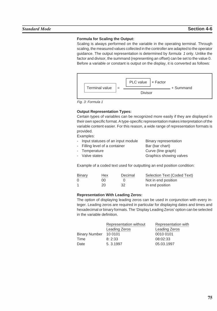
75
Standard Mode Section 4-6
Formula for Scaling the Output:Scaling is always performed on the variable in the operating terminal. Throughscaling, the measured values collected in the controller are adapted to the operatorguidance. The output representation is determined by formula 1 only. Unlike thefactor and divisor, the summand (representing an offset) can be set to the value 0. Before a variable or constant is output on the display, it is converted as follows:
PLC value × Factor
Terminal value = + SummandDivisor
Fig. 3: Formula 1
Output Representation Types:Certain types of variables can be recognized more easily if they are displayed intheir own specific format. A type-specific representation makes interpretation of thevariable content easier. For this reason, a wide range of representation formats isprovided.Examples:- Input statuses of an input module Binary representation- Filling level of a container Bar (bar chart)- Temperature Curve (line graph)- Valve states Graphics showing valves
Example of a coded text used for outputting an end position condition:
Binary Hex Decimal Selection Text (Coded Text)0 00 0 Not in end position1 20 32 In end position
Representation With Leading Zeros:The option of displaying leading zeros can be used in conjunction with every in-teger. Leading zeros are required in particular for displaying dates and times andhexadecimal or binary formats. The ‘Display Leading Zeros’ option can be selectedin the variable definition.
Representation without Representation withLeading Zeros Leading Zeros
Binary Number 10 0101 0010 0101Time 8: 2:33 08:02:33Date 5. 3.1997 05.03.1997
76
Standard Mode Section 4-6
4.6.1.1 ‘Decimal Number’ Representation
The decimal representation of numbers is the most frequently used representationmethod. The operating concept differentiates between the following decimal number typesof representation: Standard, Timer, Counter and BCD-Format.Decimal representation includes integers and floating point numbers.
4.6.1.1.1 ‘Standard’ Variable Type
The positional significance of the displayed positions increases from right to left.Leading zeros or the decimal point can be displayed as an option. Decimal repre-sentation is suitable for the data types Bit, Byte, Word and Lword. The maximumlength depends on the data type. There are no blanks between the characters. Inthe controller, this variable is in the binary format or special timer or counter for-mats.
103 102 101 100 10-1 10-2 Positional significance0 1 2 3 4 5 Display (123,45D)
4.6.1.1.2 ‘Timer’ Variable Type
The variable type Timer has a special function only when used in combination withSimatic S5 controllers.The kind of formatting of the variable type Timer depends on the memory area ofthe PLC where the value was read. If the value is read directly from a timer word, the10 bit binary time value contained in it and the 2-bit time base are converted to thetime value to the base 10 ms. If read from a different memory area, i.e. data word(DW), flag word (MW), input word (EW) or output word (AW), it is then assumed thatthe value is BCD-coded (3 digits BCD-code and 2 bit time base). This value will alsobe converted to a time value to the base 10 ms.The resulting time value to the base 10 ms can now be formatted in the same wayas a fixed point number, i.e. use of post-decimal places is possible and scaling canbe applied.
Example:A setpoint value is entered on the operating terminal: Address MW100The current actual value is displayed on the operating terminal: Address MW200
Representation InputVariable:
Decimal Number / Timer / 7 Digits / 2 Post-DecimalPlaces / Factor 1 /Divisor 1 / Summand 0
Representation OutputVariable:
Decimal Number/ Timer / 6 Digits / 1 Post-DecimalPlace/ Factor 1 / Divisor 10 / Summand 0
The command sequence
L MW 100SI T 1
has caused the BCD-coded time value to be loaded into flag word 100.
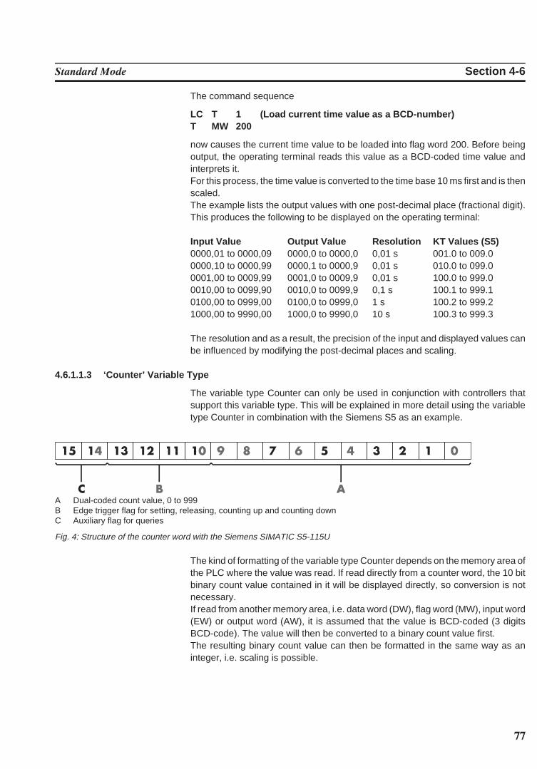
77
Standard Mode Section 4-6
The command sequence
LC T 1 (Load current time value as a BCD-number)T MW 200
now causes the current time value to be loaded into flag word 200. Before beingoutput, the operating terminal reads this value as a BCD-coded time value andinterprets it. For this process, the time value is converted to the time base 10 ms first and is thenscaled.The example lists the output values with one post-decimal place (fractional digit).This produces the following to be displayed on the operating terminal:
Input Value Output Value Resolution KT Values (S5)0000,01 to 0000,09 0000,0 to 0000,0 0,01 s 001.0 to 009.00000,10 to 0000,99 0000,1 to 0000,9 0,01 s 010.0 to 099.00001,00 to 0009,99 0001,0 to 0009,9 0,01 s 100.0 to 999.00010,00 to 0099,90 0010,0 to 0099,9 0,1 s 100.1 to 999.10100,00 to 0999,00 0100,0 to 0999,0 1 s 100.2 to 999.21000,00 to 9990,00 1000,0 to 9990,0 10 s 100.3 to 999.3
The resolution and as a result, the precision of the input and displayed values canbe influenced by modifying the post-decimal places and scaling.
4.6.1.1.3 ‘Counter’ Variable Type
The variable type Counter can only be used in conjunction with controllers thatsupport this variable type. This will be explained in more detail using the variabletype Counter in combination with the Siemens S5 as an example.
A Dual-coded count value, 0 to 999B Edge trigger flag for setting, releasing, counting up and counting downC Auxiliary flag for queries
Fig. 4: Structure of the counter word with the Siemens SIMATIC S5-115U
The kind of formatting of the variable type Counter depends on the memory area ofthe PLC where the value was read. If read directly from a counter word, the 10 bitbinary count value contained in it will be displayed directly, so conversion is notnecessary.If read from another memory area, i.e. data word (DW), flag word (MW), input word(EW) or output word (AW), it is assumed that the value is BCD-coded (3 digitsBCD-code). The value will then be converted to a binary count value first.The resulting binary count value can then be formatted in the same way as aninteger, i.e. scaling is possible.
78
Standard Mode Section 4-6
4.6.1.1.4 ‘BCD-Number’ Variable Type
The BCD format is partially used to represent numbers in the PLC. This output isrequired in special cases. The positional significance of the displayed digits in-creases from right to left. The numbers 0 to 9 are used for the representation;leading zeros can be included optionally. The BCD mode of representation is suit-able for the data types Byte, Word and Lword. The length is limited to a maximum of8 digits. There are no blanks between the characters. The variable value is storedin the controller in BCD format. The range of numbers for a byte is 00 to 99.
104 103 102 101 100 Positional significance0 1 2 3 4 Display (1234D)
4.6.1.2 ‘Alphanumerical’ Representation
In the alphanumerical mode of representation, ASCII strings are read from thecontroller in byte format and are represented on the display. The number of charac-ters which can be displayed depends on the capabilities of the type of terminalinvolved. One display line is the maximum permissible length for a variable; longertexts are truncated. The address in the variable list indicates the beginning of thecharacter string. A definition of the variable size is not included and is not neces-sary. The alphanumerical representation provides another means of editing masktexts during runtime.
4.6.1.3 ‘Selection Text’ Representation
In the Selection Text mode of representation, a text string is assigned to a numer-ical value. This allows two different tasks to be performed:1. visualization or selection of statuses by means of text strings2. change of mask.
An example of using a one-line selection text is the option of selecting the parity fora serial interface.In this case, the text list will contain three entries:
Value Text0 No Parity1 Odd2 Even
A variable (ComParityA / ComParityB ) is created in the mask.Only these three options are selectable on the operating terminal by means of theStandard or Mix-Mode Editor; invalid inputs are therefore prevented.
79
Standard Mode Section 4-6
Multiple-line selection texts are primarily used for menu control. Unlike one-lineselection texts, multiple-line selection texts display the text list either in full or inpart. If the value for the selection text field height is less than the number of textelements to be displayed, the cursor keys can be used to scroll through the textelements. After the final text list entry is reached, the selection proceeds with thefirst entry.To indicate that a text is selected, the entire selection text line is represented in theinverse format. With the representation type Selection Text, text lists are also used to assign masknames to the mask numbers:
Value Text10 Machine parameters20 Serial message mask30 Status messages40 Message configuration50 Interface parameters
A variable (NewMask ) of the type Selection Text is created in the Main Mask withthe maximum height of 5 lines and a length of 25 characters. The values in the textlist and the mask numbers must match.One of these entries can then be selected from the selection field displayed on theoperating terminal: the desired mask is then displayed.
4.6.1.4 ‘Selection Image’ Representation
In the Selection Image mode of representation, an image (pixel graphic) is as-signed to a numerical value. This image is assigned in an image list. The image listis linked to the variable whose values are to be represented as images. In this way,language-independent visualization of operating states, inputs and outputs, etc. ispossible.Numbers may be freely assigned to the images. They need not necessarily becontiguous or sorted in a consecutive order. In addition, a default image exists forevery image list which is displayed, whenever the variable assumes a value thatdoes not exist in the image list. The images used are cut to the size that applies tothe output format. This representation is limited to bits, bytes or words. Selectionimage variables can be both displayed and edited using the +/- key (as with theSelection Text Editor). Any modifications that are made are directly transferred tothe controller.
The example below illustrates how images are assigned to numerical values:
Value Image Name120 Symbol134 Symbol27 Symbol31201 Symbol4
80
Standard Mode Section 4-6
The names for the images represent the images in the image list. The actual list willlook something like this:
This image list has been defined with four entries. The graphic selected by thecontroller will be displayed.
All of the images in an image list should have the same output size to ensure thatthey overwrite (overlap) each other completely. An I/O mask can contain multipleselection image variables. These selection image variables can be of the types:one-time output variable, cyclical output variable, or input variable. When the cycli-cal output of selection images (‘animation’) is chosen, it must be remembered thatthe rate of change will be slow due to the limitations of the hardware performance.The more images that are output, the smaller the output performance. The selec-tion image variable should therefore mainly be used for switching states or nearlystatic processes.
4.6.1.5 ‘Floating Point Number’ Representation
The rules that apply to the Floating Point Number mode of representation are basi-cally the same as those applying to the representation type Decimal Number -variable type Standard. The only difference is that with this representation type, thefactor that is used to achieve scaling can be a floating point number; a divisor istherefore not required. With floating point numbers, the reciprocal value can alsobe generated, before the value is displayed.Not every controller type supports the floating point format. There are differentfloating point formats available for processing in the controller (for example, theIEEE format).
4.6.1.6 ‘Hexadecimal Number’ Representation
The hexadecimal representation of numbers is frequently used to display address-es when the PLC is programmed. This format is aimed for use by more experiencedoperators! The positional significance of the displayed digits increases from right toleft. Numbers are expressed by the characters 0 to 9 and A to F. Only capital lettersand leading zeros are used for representation. The hexadecimal representation issuitable for the data types Byte, Word and Lword. The length is limited to a maxi-mum of 8 digits. There are no blanks between the characters.
164 163 162 161 160 Positional significance0 E 4 5 A Display (0E45AH)
81
Standard Mode Section 4-6
4.6.1.7 ‘Binary Number’ Representation
The binary format permits the representation of single bits, bytes, words or Lwords.The value for the ‘length’ entered in the variable definition corresponds to the num-ber of bits to be represented. Counting always begins with bit 0. The number ofblanks indicates how many gaps (spaces) are inserted between each bit. Output isalways in the horizontal position. The direction of the positional significance can beset in the variable definition.
Bit 3 Bit 2 Bit 1 Bit 00 1 0 0 Direction = 76543210Bit 0 Bit 1 Bit 2 Bit 30 0 1 0 Direction = 01234567
0100 Blanks = 00 1 0 0 Blanks = 10 1 0 0 Blanks = 2
4.6.1.8 Bar Representation
Variables in I/O masks can be represented as bars. They can be programmed to beeither horizontal or vertical. The bars can start at a reference point (e.g. in thecenter of the display) and extend in both the positive and the negative direction.The range of values of the bars can be defined by specifying the upper and lowerlimit (corner values). The bars are represented on the terminal with the aid of fourdifferent graphical objects, the simplest of which is a fill pattern. Separate fill pat-terns can be specified for:
- the empty part of the bar- the filled-in bar- the ‘lower limit exceeded’ bar- the ‘upper limit exceeded’ bar
The programming software includes seven default fill patterns for representingbars on the operating terminal. The other, above-mentioned graphical objects canalso be used to design your own fill patterns and shapes.
Fig.5: Different forms of bar representation
82
Standard Mode Section 4-6
Bar charts can be output once only, cyclically or after defined events (event-con-trolled). They are used purely to indicate actual values.
The range of values for outputs extends from -32768 to +32767.
If your mask contains several bars, you should address the variables suchthat they can be transferred contiguously.
Each bar varies between a lower limit and an upper limit. Outside these limits, itchanges to the predefined fill pattern for Upper or Lower Limit Exceeded.
Possible applications:- Vertical and horizontal trend displays- Visualized monitoring of limit values- Histograms- Filling-level indications
Example of a filling-level indication:
Bitmap:
Lower Limit Exceeded
Intermediate ValueBitmap:
Lower Limit
Bitmap:
Upper Limit
Bitmap:
Upper Limit Exceeded
Fig. 6: Example of a filling-level indication
The bar mode of representation always means a slower output rate. Each bartherefore always corresponds to an integer multiple of a character. The smallestpossible bar is equivalent in size to a single character, while the largest bar coversthe entire display. The bars ‘grow’ one pixel at a time.
4.6.1.9 Curve Representation (Trendline)
The curve mode of representation permits value tables to be output as dotted lines.A ‘curve’ variable must be defined in a mask in order to represent a curve. The sizeof the curve is determined by its length and height. If a coordinate system is requir-ed, it can be displayed with the aid of background images.The address of the curve variable represents the start of a value table in the PLC.Each value in the table describes one pixel on the curve. The graphical repre-sentation of the value table resembles that for cyclic output variables.
Examples of a variable time history:- Output of one-time processes- Memory function of a point recorder- Filling-level curves
A curve is limited by the following parameters:- Maximum height: Height of the display- Maximum width: 54 pixels per curve variable
83
Standard Mode Section 4-6
If you need a width of more than 54 pixels, you can output several curves directlyadjacent to one another.
Fig. 7: Example of a curve representation
The height information, in other words the variable values, is read from the controll-er in a contiguous field by means of one read job. The height information in the fieldelement with the starting address (address + 0) is displayed on the far left. Allsubsequent height information (address + n) is shifted one pixel position to theright. The curve height information is refreshed cyclically.The output is thereby deleted and written again one pixel at a time.Only two parameters are required to represent a curve:- Curve width as a multiple of the character width (normal font)- Curve height as a multiple of the character height (normal font)
4.6.2 Input VariablesInput variables, when displayed for the first time (when the mask is activated), aretreated in the same way as one-time output variables, i. e. the same representationoptions are available. This includes the scaling effect.
Scaling is performed on the value in the PLC .
Input variables can be modified in the terminal by means of Editors. Their function-ality is determined by the type of Editor that is selected. The Editors that are supported for variable input are the same as those supportedfor variable output. Editing of the variables is subject to certain conditions whichmust take into consideration by the user when creating the project, such as thepassword protection and the external data release, for example.The following must be observed when entering timers and counters:
TimerWhen writing to a timer variable, any scaling that may have been performed is firstreversed to give the time value to the base 10 ms again. The BCD-coded value isthen calculated so that the lowest possible time base is used.Avoid writing to a timer word in the PLC, as this has uncontrolled results onthe control bits.
84
Standard Mode Section 4-6
CounterWhen writing to a counter variable, any scaling that may have been performed isfirst reversed. The BCD-coded value is then computed and transferred to the PLC.Avoid writing to a counter word in the PLC, as this has uncontrolled resultson the control bits.
Formula for Scaling Input ValuesInput values transferred by the PLC are processed according to formula 1 beforebeing displayed. After the values have been edited, they are processed in accord-ance with the inverse function (formula 2) before being transferred back to the PLC.The inverse function will automatically be generated in the terminal. Operandsmust be defined by the user on the basis of the values in the PLC including the inputvalue.
Input value × Summand
PLC value = × DivisorFactor
Fig. 8: Formula 2
During conversion, the last digit is automatically rounded. This must be kept in mindwhen defining the upper limit.
(Input value × Factor) , (Pos. Upper Limit - Divisor / 2)
Fig. 9: Formula 3
Plausibility CheckA plausibility check is performed on all input variables. As a part of this check, theentered value is validated against the upper and lower limits specified in the vari-able definition. System messages are generated if the entered value is outsidethese limits. In this case, the invalid value will not be transferred to the controllerand the previous (valid) value will be retained.
If the system message texts ‘Value too large’ and ‘Value too small’ are deleted, thefollowing applies:- if the value drops below the limit, the value corresponding to the lower limit is
used- if the value exceeds the upper limit, the value corresponding to the upper limit is
used.A system message is not output during this process.
Help Text for Input VariablesA screen-sized help text can be created for each input variable. This help text canbe displayed in the Editor by pressing the Help key. Important information to beinserted in a help text may include the upper and lower limits, the impact of vari-ables on the process to be carried out, or any interactions with other variables.
If a variable-specific help text is not defined, the default help text will be displayedinstead. This is also a screen-sized text which can be edited in the programmingsoftware. If a default help text is not defined, a blank mask will be displayed.
85
Standard Mode Section 4-6
4.6.3 System VariablesSystem variables can be used to control terminal-internal functions.System variables can be referenced to function keys and soft keys. They can alsobe used in masks as normal variables for input and output processes.
The following applies if a system variable is linked to a function key or soft key:- do not link a change of mask function and a system variable to the same key- it is not necessary that the same function key or soft key is used to set (1) and
reset (0) a system variable- jogging mode is obtained by using the same function key or soft key to set (1)
and reset (0) a system variable.
Do not include the names of system variables in the variable list. If the name of asystem variable is referenced to a PLC address, it will loose its terminal-internalfunction.The following subchapters list the system variables, organized into separategroups of functionality, and describes their functions.
4.6.3.1 Basic Functions
IntEraseEpromAllows the user description to be erased from the Flash memory and prepares theterminal for a new download via interface channel SER2. There will be no commu-nication with any connected PLC during this process. Writing of a ‘1’ to this variableerases the user description unconditionally. Subsequently, the variable is automat-ically reset to ‘0’.
Data type: NumericEditor: Selection text , positive decimal numberOutput: ---Possible values: (0) Inactive Initial state
(1) Active Erases the user description
MainVersionAllows the user to display the current firmware version of the operating terminal.
Data type: AlphanumericEditor: ---Output: Alphanumeric, 8 charactersPossible values: Format specified by manufacturer
ComVersionIs used to display the type and version number of the current communication proto-col.
Data type: AlphanumericEditor: ---Output: Alphanumeric, 8 charactersPossible values: Format specified by manufacturer
86
Standard Mode Section 4-6
UserVersionIndicates the version number of the project description to the operator. The userenters this number into the programming system during programming time.
Data type: NumericEditor: ---Output: Numeric, 3 digitsPossible values: ---
BootThis variable can be used to initiate the terminal to boot (system restart). The vari-able is suitable for integrating the setup function into the regular operator guidance,making it possible to modify terminal parameters which require a subsequent rein-itialization (system restart) in any I/O mask. The terminal is booted if a ‘1’ is writtento this variable. Subsequently, the variable is automatically reset to ‘0’.
Data type: NumericEditor: Selection text , positive decimal numberOutput: ---Possible values: (0) Inactive Initial state
(1) Active System restart
LCDContrastIs used to adjust the contrast for terminals with liquid crystal displays.
Data type: NumericEditor: IntegerOutput: ---Possible values: -127 to +127 (to be limited further based on terminal
type)
LCDBackgroundIs used to adjust the background of the display. This variable is only relevant foroperating terminals fitted with a corresponding display.
Data type: NumericEditor: Selection text , positive decimal numberOutput: ---Possible values: (0) Normal representation
(1) Inverse background
LCDBackLightIs used to adjust the background lighting of the display. This variable is only rele-vant for operating terminals fitted with a corresponding display.
Data type: NumericEditor: AnyOutput: ---Possible values: (0) Background lighting OFF
(1 to x) Background lighting ON (dimmed)
87
Standard Mode Section 4-6
TurnOnTempIs used to ensure that the liquid crystal display of the operating terminal is notturned on until a certain ambient temperature is reached. This variable is only rele-vant for operating terminals provided with a corresponding functionality in conjunc-tion with the corresponding display.
Data type: NumericEditor: Selection text , positive decimal numberOutput: ---Possible values: (0) LCD-display OFF
(1 to x) value of the temperature at which the LCD-display is turned ON
OsLanguageWith multilingual user descriptions, this variable is used for online language selec-tion.
Data type: NumericEditor: Selection textOutput: ---Possible values: (0) First language
(n) nth language
4.6.3.2 Communication SER1
ComDataLenADefines the number of data bits for the communication via SER1.
Data type: NumericEditor: Selection text , positive decimal numberOutput: ---Possible values: (0) 5bits/Char
(1) 6bits/Char(2) 7bits/Char(3) 8bits /Char
ComParityADetermines the creation of and check method of the parity for the communicationvia SER1.
Data type: NumericEditor: Selection text , positive decimal numberOutput: ---Possible values: (0) No Parity
(1) Odd Parity(2) Even Parity.
88
Standard Mode Section 4-6
ComStopBitsADefines the number of stop bits for the communication via SER1.
Data type: NumericEditor: Selection text , positive decimal numberOutput: ---Possible values: (0) 1 bit
(1) 1.5 Bits(2) 2 bits
ComBaudrateADefines the baud rate for the communication via SER1.
Data type: NumericEditor: Selection text , positive decimal numberOutput: ---Possible values: (0) 300 Bd
(1) 600 Bd(2) 1200 Bd(3) 2400 Bd(4) 4800 Bd(5) 9600 Bd(6) 19200 Bd(7) 38400 Bd
ComHandshakeASpecifies the type of handshake for the communication via SER1.
Data type: NumericEditor: Selection text , positive decimal numberOutput: ---Possible values: (0) No handshake
(1) RTS/CTS hardware handshake(2) XON/XOFF software handshake
ComDefaultAThis variable can be used to program new parameters for SER1.
Data type: NumericEditor: Selection text , positive decimal numberOutput: ---Possible values: (0) Inactive Initial state
(1) Active The data entered into the associatedsystem variables are accepted asthe new parameters.
(2) Active The data stored in the Flash memo-ry by the programming software areaccepted as the new parameters.
89
Standard Mode Section 4-6
ComTimeoutSpecifies the monitoring period for SER1. The value (0) deactivates the timeoutmonitoring function.
Data type: NumericEditor: Positive decimal numberOutput: ---Possible values: (0) Inactive Initial state
(1 to 65535) Timeout monitoring active (time inms)
ComRetryTimeoutSpecifies the period of time, in milliseconds, that the terminal allows to elapse afteran attempt to establish a connection via SER1 failed, before making another at-tempt. This allows the time period required for the PLC-specific powerup phase tobe bridged, thereby avoiding the generation of an error message.
Data type: NumericEditor: Positive decimal numberOutput: ---Possible values: 0 to 65535 ms
ComSlaveNrContains the slave number used for the device on the network. This addresscan be used to address the operating terminal on the bus.
Data type: NumericEditor: Positive decimal numberOutput: Positive decimal numberPossible values: 0 to 255
4.6.3.3 Error Statistics SER1
ComParityCountError counter for monitoring of parity errors on SER1 to the PLC. Is erased on everydownload.
Data type: NumericEditor: (Possible)Output: Positive decimal numberPossible values: 0 to 65535
ComOverrunCountError counter for monitoring of overrun errors on SER1 to the PLC. Is erased onevery download.
Data type: NumericEditor: (Possible)Output: Positive decimal numberPossible values: 0 to 65535
90
Standard Mode Section 4-6
ComFrameCountError counter for monitoring of framing errors on SER1 to the PLC. Is erased onevery download.
Data type: NumericEditor: (Possible)Output: Positive decimal numberPossible values: 0 to 65535
ComStatisticsTabThe system variable points to the beginning of the protocol statistics table with 6elements of 4 bytes each.
Data type: Positive decimal numberEditor: ---Output: TablePossible values: ---
ComErrorTabThe system variable points to the beginning of a table with 16 elements whichcontain the most recent 16 communication errors.
Data type: Positive decimal numberEditor: ---Output: TablePossible values: ---
ComSubcodeTabThe system variable points to the beginning of a table with 16 elements whichcontain the subcodes of the communication errors.
Data type: Positive decimal numberEditor: ---Output: TablePossible values: ---
4.6.3.4 Communication SER2
ComDataLenBDefines the number of data bits on SER2.
Data type: NumericEditor: Selection text , positive decimal numberOutput: ---Possible values (0) 5 bits/char
(1) 6 bits/char(2) 7 bits/char(3) 8 bits/char
91
Standard Mode Section 4-6
ComParityBDetermines the creation of and check method for the parity bit for SER2.
Data type: NumericEditor: Selection text , positive decimal numberOutput: ---Possible values: (0) No parity
(1) Odd parity(2) Even parity
ComStopBitsBDefines the number of stop bits on SER2.
Data type: NumericEditor: Selection text , positive decimal numberOutput: ---Possible values: (0) 1 bit
(1) 1.5 bits(2) 2 bits
ComBaudrateBDefines the baud rate on SER2.
Data type: NumericEditor: Selection text , positive decimal numberOutput: ---Possible values: (0) 300 Bd
(1) 600 Bd(2) 1200 Bd(3) 2400 Bd(4) 4800 Bd(5) 9600 Bd(6) 19200 Bd(7) 38400 Bd(8) 57600 Bd
ComHandshakeBSpecifies the type of handshake on SER2.
Data type: NumericEditor: Selection text , positive decimal numberOutput: ---Possible values: (0) No handshake
(1) RTS/CTS hardware handshake(2) XON/XOFF software handshake
ComDefaultBThis variable can be used to program new parameters for SER2.
92
Standard Mode Section 4-6
Data type: NumericEditor: Selection text , positive decimal numberOutput: ---Possible values: (0) Inactive Initial state
(1) Active The data entered into the associatedsystem variables are accepted asthe new parameters.
(1) Active The data stored in the Flash memo-ry by the programming software areaccepted as the new parameters.
4.6.3.5 Real-Time Clock
RTCSecThis variable is used to display and set the seconds of the clock.
Data type: Positive decimal numberEditor: Positive decimal numberOutput: Positive decimal numberPossible values: 0 to 59
RTCMinThis variable is used to display and set the minutes of the clock.
Data type: Positive decimal numberEditor: Positive decimal numberOutput: Positive decimal numberPossible values: 0 to 59
RTCHourThis variable is used to display and set the hours of the clock.
Data type: Positive decimal numberEditor: Positive decimal numberOutput: Positive decimal numberPossible values: 0 to 23
RTCDayThis variable is used to display and set the day of the month.
Data type: Positive decimal numberEditor: Positive decimal numberOutput: Positive decimal numberPossible values: 0 to 31 (varies from month to month, clock corrects in-
correct entries on the next change of date)
RTCMonthThis variable is used to display and set the month of the year.
Data type: Positive decimal numberEditor: Positive decimal numberOutput: Positive decimal numberPossible values: 0 to 12
93
Standard Mode Section 4-6
RTCYearThis variable is used to display and set the year.
Data type: Positive decimal numberEditor: Positive decimal numberOutput: Positive decimal numberPossible values: 0 to 99 (only the year and the decade are influenced)
RTCDayofWeekThis variable is used to display and determine the day of the week. The variableassumes the values 0 to 6. This is a modulo counter. A coded text should be usedfor the display. The assignment and starting point can be specified as needed.
Data type: Positive decimal numberEditor: Selection text Output: Selection text Possible values: 0 to 6
RTCDateFmtIs used to enter the format according to which the date is to appear in displayedmessages.
Data type: NumericEditor: Selection text , positive decimal numberOutput: ---Possible values: (0) European DD MM YY
(1) US MM DD YY(2) JAPAN JJ MM DD
RTCYear2000This variable is used to display and set the year in a 4-digit format.
Data type: NumericEditor: Selection text , selection image, alphanumeric, deci-
malOutput: ---Possible values: 0 to 9999
4.6.3.6 Serial Message System
RepmanSortCritIs used to enter the sorting criterion for the serial message output.
Data type: NumericEditor: Selection text , positive decimal numberOutput: ---Possible values: (0) By priority of message number
(1) By time of arrival (newest first)(2) By time of arrival (oldest first)
94
Standard Mode Section 4-6
ClearRepBufIs used to erase the entire serial message buffer. Optionally direct control via func-tion keys, soft keys or Editor. If necessary, passwords or special masks should beimplemented to control erasure of the message buffer.
Data type: NumericEditor: Selection text , positive decimal numberOutput: ---Possible values: (0) Maintain data
(1) Erase message buffer
RepmanRepPrintSwitches the output of messages via the printer on and off.
Data type: NumericEditor: Selection text , positive decimal numberOutput: ---Possible values: (0) Off
(1) On
RepoutNrSwitches the output of the message number in the message mask on and off.
Data type: NumericEditor: Selection text , positive decimal numberOutput: ---Possible values: (0) Off
(1) On
RepoutDateSwitches the output of the date of the message in the message mask on and off.
Data type: NumericEditor: Selection text , positive decimal numberOutput:---
Possible values: (0) Off(1) On
RepoutTimeSwitches the output of the time of the message in the message mask on and off.
Data type: NumericEditor: Selection text , positive decimal numberOutput: ---Possible values: (0) Off
(1) On
95
Standard Mode Section 4-6
RepoutAnzYearDetermines the number of digits that is to be used to represent the year.
Data type: NumericEditor: Selection text , selection image, decimalOutput: ---Possible values: (0) year represented by 2 digits
(1) year represented by 4 digits
RepoutRepTextIs used to display the most current serial message. The message is displayed in thesame way as it would appear in the message mask, i.e. in accordance with theselected message parameters.
Data type: AlphanumericEditor: ---Output: AlphanumericPossible values: Any
RepoutRepText21Is used to display the most current message of the serial message system - fromthe 21st digit with a variable length (20, 40 or 60). The message is displayed in thesame way as it would appear in the message mask, i.e. in accordance with theselected message parameters.
Data type: AlphanumericEditor: ---Output: AlphanumericPossible values: Any
RepoutRepText41Is used to display the most current message of the serial message system - fromthe 41st digit with a variable length (40 or 60). The message is displayed in thesame way as it would appear in the message mask, i.e. in accordance with theselected message parameters.
Data type: AlphanumericEditor: ---Output: AlphanumericPossible values: Any
RepoutRepText61Is used to display the most current message of the serial message system - fromthe 61st digit. The last 20 characters of a message are displayed. The message isdisplayed in the same way as it would appear in the message mask, i.e. in accord-ance with the selected message parameters.
Data type: AlphanumericEditor: ---Output: AlphanumericPossible values: Any
96
Standard Mode Section 4-6
4.6.3.7 Parallel Message System
RepmanSortCritPThis variable indicates to the terminal the sorting criterion according to which themessages are to be displayed. The default value is defined in the user description.This variable can be adapted during editing processes at a later date.
Data type: NumericEditor: Selection text , positive decimal numberOutput: ---Possible values: (0) By priority of message number
(1) By time of arrival (newest first)(2) By time of arrival (oldest first)
RepoutNrPThis variable indicates to the terminal whether or not the message number is to bedisplayed along with the message text of messages in the parallel message sys-tem. The default value is defined in the user description. This variable can beadapted during editing processes at a later date.
Data type: NumericEditor: Selection text , positive decimal numberOutput: ---Possible values: (0) Off
(1) On
RepoutDatePThis variable indicates to the terminal whether or not the date is to be displayedalong with the message text of messages in the parallel message system. Thedefault value is defined in the user description. This variable can be adapted duringediting processes at a later date.
Data type: NumericEditor: Selection text , positive decimal numberOutput: ---Possible values: (0) Off
(1) On
RepoutTimePThis variable indicates to the terminal whether or not the time is to be displayedalong with the message text of messages in the parallel message system. Thedefault value is defined in the user description. This variable can be adapted duringediting processes at a later date.
Data type: NumericEditor: Selection text , positive decimal numberOutput: ---Possible values: (0) Off
(1) On
97
Standard Mode Section 4-6
RepoutAnzYearPDetermines the number of digits that is to be used to represent the year.
Data type: NumericEditor: Selection text , selection image, alphanumeric, binary,
decimal, hexadecimalOutput: ---Possible values: (0) year represented by 2 digits
(1) year represented by 4 digits
RepoutRepTextPThe terminal uses this variable to display the most current message of the parallelmessage system.
Data type: AlphanumericEditor: ---Output: AlphanumericPossible values: Any
RepoutRepTextP21Is used to display the most current message of the parallel message system - fromthe 21st digit with a variable length (20, 40 or 60). The message is displayed in thesame way as it would appear in the message mask, i.e. in accordance with theselected message parameters.
Data type: AlphanumericEditor: ---Output: AlphanumericPossible values: Any
RepoutRepTextP41Is used to display the most current message of the parallel message system - fromthe 41st digit with a variable length (40 or 60). The message is displayed in thesame way as it would appear in the message mask, i.e. in accordance with theselected message parameters.
Data type: AlphanumericEditor: ---Output: AlphanumericPossible values: Any
RepoutRepTextP61Is used to display the most current message of the parallel message system - fromthe 61st digit. The last 20 characters of a message are displayed. The message isdisplayed in the same way as it would appear in the message mask, i.e. in accord-ance with the selected message parameters.
Data type: AlphanumericEditor: ---Output: AlphanumericPossible values: Any
98
Standard Mode Section 4-6
4.6.3.8 Printer Control
StopPrintWhen the system variable is activated, the print process currently in progress isterminated.
Data type: NumericEditor: Selection text , positive decimal number, soft key,
function keyOutput: ---Possible values: (0) Initial state
(1) Terminate print process
BlockPrintUpon activation of this system variable, the block selected in the message mask isprinted.
Data type: NumericEditor: Selection text , positive decimal number, soft key,
function keyOutput: ---Possible values: (0) Initial state
(1) Print block
PrintAllRepUpon activation of this system variable, the entire serial message memory is print-ed. The output is as predefined.
Data type: NumericEditor: Selection text , positive decimal number, soft key,
function keyOutput: ---Possible values: (0) Initial state
(1) Formatted printout(2) Full-length printout
PrintAllStateUpon activation of this system variable, the entire parallel message memory (sta-tus messages) is printed.
Data type: NumericEditor: Selection text , positive decimal number, soft key,
function keyOutput: ---Possible values: (0) Initial state
(2) Print message buffer
99
Standard Mode Section 4-6
BlockPrintLongUpon activation of this system variable, the entire area selected in a message maskis printed in full length. The settings chosen at programming are ignored.
Data type: NumericEditor: Selection text , positive decimal number, soft key,
function keyOutput: ---Possible values: (0) Initial state
(1) Print selected area
4.6.3.9 Menu Control / Keys
NewMaskIf a mask number is written to this system variable, the system will switch to thecorresponding mask.
Data type: NumericEditor: Selection text, selection fieldOutput: ---Possible values: 1 to 9999
VarTablenR0Generates a consecutive numbering in tables beginning with the number ‘0’. Thissystem variable is also used to output constant table texts.
Data type: NumericEditor: ---Output: Selection text, positive decimal numberPossible values: 0 to n
VarTablenR1Generates a consecutive numbering in table beginning with the number ‘1’. Thissystem variable is also used to output constant table texts.
Data type: NumericEditor: ---Output: Selection text, positive decimal numberPossible values: 1 to n
HardCopyIs used to upload a hard copy in PCX or ASCII format via interface X3 to the con-nected PC.
Data type: NumericEditor: Selection text, positive decimal number, soft key,
function keyOutput: ---Possible values: (0) Initial state
(1) Activate hard copy (always currently displayedscreen)
100
Standard Mode Section 4-6
TabLeftIn tables, this system variable can be used to shift to the column on the left.
Data type: NumericEditor: Soft key, function keyOutput: ---Possible values: (0) Initial state
(1) To the left by one column
TabRightIn tables, this system variable can be used to shift to the column on the right.
Data type: NumericEditor: Soft key, function keyOutput: ---Possible values: (0) Initial state
(1) To the right by one column
TabPgUpThis system variable enables soft keys to be used in tables to shift from page topage (in an upward direction).
Data type: NumericEditor: Soft key, function keyOutput: ---Possible values: (0) Initial state
(1) Move up one page
TabPgDnThis system variable enables soft keys to be used in tables to shift from page topage (in a downward direction).
Data type: NumericEditor: Soft key, function keyOutput: ---Possible values: (0) Initial state
(1) Move down one page
ShiftWhen the system variable is set, alphanumerical characters can be entered. Whenthe keys on the numerical keypad are pressed, the associated alphabetical lettersare automatically provided. By pressing repeatedly, you can proceed through theassociated letters. Only uppercase letters are provided.
Data type: NumericEditor: Soft key, function keyOutput: ---Possible values: (0) Initial state, numbers only
(1) Shift mode 1 active, uppercase letters
101
Standard Mode Section 4-6
Key Letters (Characters)Point : ? ! .Minus \ * / -Plus , = . +Zero ( ) ˚ 0One S T U 1Two V W X 2Three Y Z % 3Four J K L 4Five M N O 5Six P Q R 6Seven A B C 7Eight D E F 8
ShiftCaseWhen the system variable is set, alphanumerical characters can be entered. Whenthe keys on the numerical keypad are pressed, the associated alphabetical lettersare automatically provided. By pressing repeatedly, you can proceed through theassociated letters. Uppercase and lowercase letters are provided.
Data type: NumericEditor: Soft key, Function keyOutput: ---Possible values: (0) Initial state, numbers only
(1) Shift Mode 2 active, lowercase and uppercaseletters
Key Letters (Characters)Point : ? ! .Minus \ * / -Plus , = . +Zero ( ) ˚ 0One S T U s t u 1Two V W X v w x 2Three Y Z % y z % 3Four J K L j k l 4Five M N O m n o 5Six P Q R p q r 6Seven A B C a b c 7Eight D E F d e f 8
KeyCursLeftThis system variable allows soft keys to be used as a Cursor left key.
Data type: NumericEditor: Soft key, function keyOutput: ---Possible values: (0) Initial state
(1) Treat soft key as a Cursor left key.
102
Standard Mode Section 4-6
KeyCursRightThis system variable allows soft keys to be used as a Cursor right key.
Data type: NumericEditor: Soft key, function keyOutput: ---Possible values: (0) Initial state
(1) Treat soft key as a Cursor right key
KeyCursUpThis system variable allows soft keys to be used as a Cursor up key.
Data type: NumericEditor: Soft key, function keyOutput: ---Possible values: (0) Initial state
(1) Treat soft key as a Cursor up key
KeyCursDownThis system variable allows soft keys to be used as a Cursor down key.
Data type: NumericEditor: Soft key, function keyOutput: ---Possible values: (0) Initial state
(1) Treat soft key as a Cursor down key
KeyHomeThis system variable allows soft keys to be used as a Cursor home key.
Data type: NumericEditor: Soft key, function keyOutput: ---Possible values: (0) Initial state
(1) Treat soft key as a Cursor home key
KeyHelpThis system variable allows soft keys to be used as a Help key.
Data type: NumericEditor: Soft key, function keyOutput: ---Possible values: (0) Initial state
(1) Treat soft key as a Help key
103
Standard Mode Section 4-6
KeyDotThis system variable allows soft keys to be used as a Decimal point key.
Data type: NumericEditor: Soft key, function keyOutput: ---Possible values: (0) Initial state
(1) Treat soft key as a Decimal point key
KeyClearThis system variable allows soft keys to be used as a Delete key.
Data type: NumericEditor: Soft key, function keyOutput: ---Possible values: (0) Initial state
(1) Treat soft key as a Delete key
Key0This system variable allows soft keys to be used as the key 0 (zero).
Data type: NumericEditor: Soft key, function keyOutput: ---Possible values: (0) Initial state
(1) Treat soft key as the key 0
Key1This system variable allows soft keys to be used as the key 1 .
Data type: NumericEditor: Soft key, function keyOutput: ---Possible values: (0) Initial state
(1) Treat soft key as the key 1
Key2This system variable allows soft keys to be used as the key 2.
Data type: NumericEditor: Soft key, function keyOutput: ---Possible values: (0) Initial state
(1) Treat soft key as the key 2
104
Standard Mode Section 4-6
Key3This system variable allows soft keys to be used as the key 3.
Data type: NumericEditor: Soft key, function keyOutput: ---Possible values: (0) Initial state
(1) Treat soft key as the key 3
Key4This system variable allows soft keys to be used as the key 4.
Data type: NumericEditor: Soft key, function keyOutput: ---Possible values: (0) Initial state
(1) Treat soft key as the key 4
Key5This system variable allows soft keys to be used as the key 5.
Data type: NumericEditor: Soft key, function keyOutput: ---Possible values: (0) Initial state
(1) Treat soft key as the key 5
Key6This system variable allows soft keys to be used as the key 6.
Data type: NumericEditor: Soft key, function keyOutput: ---Possible values: (0) Initial state
(1) Treat soft key as the key 6
Key7This system variable allows soft keys to be used as the key 7.
Data type: NumericEditor: Soft key, function keyOutput: ---Possible values: (0) Initial state
(1) Treat soft key as the key 7
105
Standard Mode Section 4-6
Key8This system variable allows soft keys to be used as the key 8.
Data type: NumericEditor: Soft key, function keyOutput: ---Possible values: (0) Initial state
(1) Treat soft key as the key 8
Key9This system variable allows soft keys to be used as the key 9.
Data type: NumericEditor: Soft key, function keyOutput: ---Possible values: (0) Initial state
(1) Treat soft key as the key 9
KeyPlusThis system variable allows soft keys to be used as a Plus key.
Data type: NumericEditor: Soft key, function keyOutput: ---Possible values: (0) Initial state
(1) Treat soft key as a Plus key
KeyMinusThis system variable allows soft keys to be used as a Minus key.
Data type: NumericEditor: Soft key, function keyOutput: ---Possible values: (0) Initial state
(1) Treat soft key as a Minus key
KeyEnterThis system variable allows soft keys to be used as an Enter key.
Data type: NumericEditor: Soft key, function keyOutput: ---Possible values: (0) Initial state
(1) Treat soft key as an Enter key
KeyEditThis system variable allows soft keys to be used as a Release key.
Data type: NumericEditor: Soft key, function keyOutput: ---Possible values: (0) Initial state
(1) Treat soft key as a Release key
106
Standard Mode Section 4-6
4.6.3.10 Password
MskchgPasswdIs used to enter the password into a mask.
Data type: Numeric, alphanumericEditor: AlphanumericOutput: ---Possible values: 11 characters
MskchgResPasswdIs used to erase the password currently entered; resets the access authorization.The access levels are reset on every power-up.
Data type: NumericEditor: Selection text , positive decimal number, soft key,
function keyOutput: ---Possible values: (0) Initial state
(1) Reset access authorization
ChangePasswdThis system variable can be used to modify the passwords in the terminal.
Data type: Numeric, alphanumericEditor: AlphanumericOutput: ---Possible values: 11 characters
FlashPasswdThis system variable can be used to reset the passwords to the code values spec-ified in the programming software. Useful in the case of a loss of the passwords.Make sure to make a note of the master password first.
Data type: NumericEditor: Selection text , positive decimal number, soft key,
function keyOutput: ---Possible values: (0) Initial state
(1) Reset passwords
PasswdlnactiveIs used to deactivate the password protection. The system variable is battery-backed. The most recent setting is retained when the device is turned off.
Data type: NumericEditor: Selection text , positive decimal numberOutput: ---Possible values: (0) Password protection active (initial state when
first initialization)(1) Password protection inactive (edit and view
level = 255)
107
Standard Mode Section 4-6
4.6.3.11 Recipes
SelectDSNrThis variable contains the number of the active data set. To edit the variable, theassociated Selection Text Editor must be used.
Data type: NumericEditor: Selection textOutput: Positive decimal number Possible values: 0 to 250
SelectDSNameThis variable contains the name of the active data set. To edit the variable, theassociated Selection Text Editor must be used.
Data type: AlphanumericEditor: Selection textOutput: Alphanumeric Possible values: 15 characters
DestDSNrWhen copying data sets, this variable contains the number of the destination dataset.
Data type: NumericEditor: Positive decimal numberOutput: ---Possible values: 1 to 250
DSCopyThis variable can be used to copy the active data set to the destination specified inDestDSNr .
Data type: NumericEditor: Selection text , positive decimal number, soft key,
function keyOutput: ---Possible values: (0) Initial state
(1) Copies to destination in DestDSNr(2) Copying and automatic search for a free data
set(3) Copies to destination in DestDSNr and over-
writes any existing data set.
108
Standard Mode Section 4-6
DSDeleteThis variable can be used to delete the active data set. The first data set from thesame recipe will become the new active data set.
Data type: NumericEditor: Selection text , positive decimal number, soft key,
function keyOutput: ---Possible values: (0) Initial state
(1) Deletes the data set
ActDSNameThis variable contains the name of the current data set. It can be read and in thecase of RAM-data sets, it can additionally be written.
Data type: AlphanumericEditor: AlphanumericOutput: AlphanumericPossible values: 15 characters
SelectRezeptNrThis variable contains the active recipe. The variable can also be modified outsidethe recipe mask.
Data type: NumericEditor: Numeric, Selection text Output: Numeric, Selection text Possible values: 1 to 250
DSDownloadThis variable can be used to write the active data set to the controller.
Data type: NumericEditor: Selection text , positive decimal number, soft key,
function keyOutput: ---Possible values: (0) Initial state
(1) Writes the data set to the controller
DSDnloadBreakThis variable can be used to terminate a data transfer to the controller currently inprogress.
Data type: NumericEditor: Selection text , positive decimal number, soft key,
function keyOutput: ---Possible values: (0) Initial state
(1) Terminates data set transfer
109
Standard Mode Section 4-6
DSDnloadStateThis variable can be used to monitor the data transfer to the controller.
Data type: NumericEditor: ---Output: Selection text Possible values: (0) Initial state
(1) Request for data transfer issued, but not yet re-leased by the controller
(2) Data transfer active
LoadDSNameThis variable contains the name of the last data set which has been transferred tothe controller. If the data set has already been deleted, question marks are dis-played.
Data type: AlphanumericEditor: ---Output: AlphanumericPossible values: 15 characters
StartSaveThis variable can be used to transfer data sets to the PC.
Data type: NumericEditor: Selection text Output: ---Possible values: (0) Initial state
(1) Transfer one data set to the PC(2) Transfer all data sets of a recipe to the PC(3) Transfer all data sets in the terminal to the PC
SaveStateDuring a transmission to the PC, this variable indicates the current status of thetransmission process.
Data type: NumericEditor: ---Output: Selection text Possible values: (0) Initial state
(1) One data set is transferred to the PC(2) All data sets of a recipe are transferred to the
PC(3) All data sets in the terminal are transferred to
the PC
110
Standard Mode Section 4-6
StartRestoreThis variable controls the download from the PC to the Terminal.
Data type: NumericEditor: Selection text Output: ---Possible values: (0) Initial state
(1) The terminal switches to the ready-to-receivestate
(2) The terminal terminates a transmission currentlyin progress.
RestoreStateThis variable indicates the status of the transmission from the PC to the terminal.
Data type: NumericEditor: ---Output: Selection text Possible values: (0) Initial state
(1) Data transmission in progress
RestoreLineNrThis variable indicates the current line number of the data set file. It is used to verifythe progress of the receive process and in the case of an error, for error localization.
Data type: NumericEditor: ---Output: NumericPossible values: 1 to 255
StartRezPrintThis variable can be used to print data sets.
Data type: NumericEditor: Selection text Output: ---Possible values: (0) Initial state
(1) Starts data set printout(2) Terminates print process
RezPrintStateWhen printing data sets, this variable indicates the current printing status.
Data type: NumericEditor: ---Output: Selection text Possible values: (0) Initial state
(1) Data set printout in progress
111
Standard Mode Section 4-6
StartUploadThis variable can be used to read, for the active recipe, a data set from the controllerand to store it in the terminal.
Data type: NumericEditor: Selection text Output: ---Possible values: (0) Initial state
(1) Variables are read individually from their speci-fied addresses
(2) Variables are read as a block from the bufferspecified for the recipe
(3) Variables are read individually from their speci-fied addresses.A free data set is automatically being searchedfor. If no free data set is available, system message18 is displayed.
(4) Variables are read as a block from the bufferspecified for the recipe.A free data set is automatically being searchedfor.If no free data set is available, system message18 is displayed.
UploadDSNrThis variable specifies the data set number to which the uploaded data set is to bewritten in the operating terminal.
Data type: NumericEditor: Numeric Output: ---Possible values: 1 to 250
UploadStateWhen uploading data sets to the operating terminal, this variable indicates theupload status.
Data type: NumericEditor: ---Output: Selection text Possible values: (0) Initial state
(1) Upload of data set in progress
112
Standard Mode Section 4-6
4.6.3.12 Running Time Meter
Counter1Counter2Counter3Counter4Counter5Counter6Counter7Counter8Is used in conjunction with the start/stop function of the associated bit as a runningtime meter. The counter is incremented while the bit is set.
Data type: NumericEditor: Positive decimal numberOutput: Positive decimal numberPossible values: 0 to 4.294.967.295
4.6.3.13 Loop-Through Operation
Pg2SpsActivates and deactivates the loop-through operation (toggle function). This func-tion must be provided by the PG protocol.
Data type: NumericEditor: Selection text , positive decimal numberOutput: ---Possible values: (0) Initial state
(2) First 1 activates, second 1 deactivates the loop-through operation
Pg2SpsStateIndicates the status of the loop-through operation.
Data type: NumericEditor: ---Output: Selection text Possible values: (0) Initial state (OFF)
(1) Issue request for loop-through operation(2) Loop-through operation possible(3) Loop-through operation active
113
Standard Mode Section 4-6
4.6.3.14 Loadable Font
ChrsetNameIs used to display the current font name.The name of the font is limited to a maximum length of 8 characters.
Data type: AlphanumericEditor: ---Output: ---Possible values: (Standard) Display using terminal font
(Font name) Display using own font
4.6.3.15 Maintenance
User1User2User3User4User5Universal variables that permit the user to store information in the terminal. Thedata are stored in the battery-backed RAM.
Data type: AnyEditor: AnyOutput: AnyPossible values: 16 bit
LCDADCInputIs used to read the current input value from the AD-converter that is used for LCDcontrast control. This value is only designed to be used for diagnosis purposes.
Data type: NumericEditor: AnyOutput: ---
LCDDACOutputIs used to read the current output value from the DA-converter that is used for LCDcontrast control. This value is only designed to be used for diagnosis purposes.
Data type: NumericEditor: AnyOutput: ---
BreakThe current Editor is interrupted and the values entered are not transferred to thecontroller. Trigger the Break function with a function key in a soft key.
Data type: NumericEditor: Function key, soft key, selection text, decimal num-
ber, binary number, hexadecimal numberOutput: ---Possible values: (0) Initial state
(1) Editing process is terminated
114
Standard Mode Section 4-6
4.6.3.16 Editors
EditInversSpecifies if the inverse representation is to be used for the Editor for inputs.
Data type: NumericEditor: AnyOutput: ---Possible values: (0) Normal representation
(1) Inverse representation
EditEnterSpecifies the behavior of the Editor when the Data Release key is pressed.
Data type: NumericEditor: ---Output: ---Possible values: (0) Editor proceeds to the next input field (default
setting)(1) Editor remains at the current position. To pro-
ceed, the cursor must be used.
StatePermSpecifies the status of the status LED in the Data Release key.
Data type: NumericEditor: AnyOutput: 0, 1, 2Possible values: (0) Status LED OFF
(1) Status LED ON(2) Status LED FLASHING
4.6.3.17 Help
StateHelpSpecifies the status of the status LED in the Help key.
Data type: NumericEditor: AnyOutput: 0, 1, 2Possible values: (0) Status LED OFF
(1) Status LED ON(2) Status LED FLASHING
MessageIn the case of a system error, the number of the system message is written to thisvariable.
Data type: NumericEditor: AnyOutput: ---Possible values: (0) Initial state
(1 to 29) System message number
115
Standard Mode Section 4-6
QuitMessageAcknowledges the system message that is currently displayed by the system vari-able Message .
Data type: NumericEditor: AnyOutput: ---Possible values: (0) Initial state
(1) Acknowledge
4.6.4 EditorsVarious Editors are available in I/O masks for the various data types. With the termEditor, we refer to program parts designed to provide a convenient method of ed-iting input variables. This sequence control required for the editing process is com-pletely integrated into the terminal. An additional ‘software’ in the controller is notrequired for this purpose. The Editors are influenced by the:- data release (particularly from the connected controller)- cyclic value refreshing- the help system and - the plausibility check.The Editors are operated with the aid of editing and control keys. For details on therespective functions consult the corresponding Editor description.The variables of the controllers can be modified using the Editors. Upon entry, thenumerical variables are checked for plausibility. The limits are determined by theuser in the variable definition. It is also possible to include a variable-specific helptext. This text may, for example, provide a description of the variable function andits valid range of values.
Variables are entered as follows: The Data Release key will allow the Editor to be activated if the I/O mask containsan editable value. When in the editing mode, the status LED in the Data Releasekey lights up and the cursor points at the first editable variable. This value can nowbe edited by using the numerical keyboard and/or the Plus/Minus keys. The valueis stored by pressing the Enter key. The value is checked for plausibility during thisprocess. If an error is detected, the status LED in the Help key will begin to flash.
A flashing status LED in the Help key indicates a malfunction to the user. A descrip-tion of the malfunction will be displayed if the Help key is pressed. In the case of anerror, the Enter key can not be used to exit the editing field.The control keys, on the contrary, can be used to exit an editing field even if thevalue is invalid. In this case, however, the last value which was entered will bediscarded and the old value (original value) will be restored. In the editing mode, control keys can be used to select editable variables. If theData Release key is pressed again, the editing mode will be exited and the statusLED will go off.The following Editors are currently available for selection in the variable definition:The functions of the keys are identical for all numerical Editors.
116
Standard Mode Section 4-6
Key Functions in the Numerical EditorKey: Cursor up Moves the cursor up on the display by one editable
variable and selects it in the process. After the cursorreaches the editable variable at the top, the variable atthe bottom is selected next.
Key: Cursor down Moves the cursor down on the display by one editablevariable and selects it in the process. After the cursor re-aches the editable variable at the bottom, the variable atthe top is selected next.
Key: Cursor left Moves the cursor within the editable variable to the leftby one position until it reaches the end of the field.
Key: Cursor right Moves the cursor within the editable variable to the rightby one position until it reaches the end of the field.
Key: Plus 1. Variable currently selected:Value is deleted, a new value can be entered
2. Cursor has been moved within a positive value:No change
3. Cursor has been moved within a negative value:Deletes the negative sign
Key: Minus 1. Variable currently selected:Value is deleted,negative sign is entered at the least significant po-sition, a new value can be entered
2. Cursor has been moved within a positive value:Negative sign is placed in front of the value
3. Cursor has been moved within a negative value:No change
Key: Delete Deletes the position where the cursor is currently located(the sign also).
4.6.4.1 Decimal Number Editor
The Decimal Number Editor is a numerical Editor, optionally for positive decimalnumbers only or for positive/negative decimal numbers.In addition, the following variable types can be selected for decimal numbers:- Standard Type Integers / fixed point numbers- Timer Timer values in S5 format- Counter Counter values in S5 format- BCD Number Decade switch / incremental Editor
The number of digits (field length) is limited to the highest displayable 4-byte num-ber. Decimal numbers can be output with leading zeros. Fixed point numbers canbe represented by specifying a certain number of post-decimal places (fractionaldigits).Other selectable options are scaling factors, limits, message transfer mode anddisplay attributes.This Editor can be used to access bit, byte, word and Lword variables. The maxi-mum limits are determined by the memory map.
The variable types Timer and Counter are represented and can be edited on theoperating terminal in the same way as the variable type Standard Type.
117
Standard Mode Section 4-6
The variable type BCD-Number has a special feature.The Editor for BCD-numbers is also referred to as the ‘Decade Switch’. With scaled variables, the value in the PLC changes by +1/-1, although the inputvalue which is actually displayed also depends on the defined scaling factor! Thismeans that special care must be taken whenever scaling is required. The Editor isalso suitable for making fine adjustments or as a decade switch with decimal carry-over.Possible Data Types:- Positive integers (no entry of signs)- Integers- Positive fixed point numbers (no entry of signs)- Fixed point numbers
Key Functions in the BCD-Number EditorKeys: 1 to 9 1.) Standard
Direct input of numerical values2.) Mix-Mode
Direct input of numerical values3.) Incremental
No FunctionKey: Plus 1.) Standard
No Function2.) Mix-Mode and Incremental
Increases the value at the cursor position and influ-ences the more significant digits when the range isexceeded (with a dynamic repeat function)
Key: Minus 1.) StandardNo Function
2.) Mix-Mode and IncrementalReduces the value at the cursor position and influ-ences the more significant digits when this valuefalls below the range (with a dynamic repeat func-tion)
Key: Cursor left Moves the cursor within the editable variable to theleft by one position until it reaches the end of the field.
Key: Cursor right Moves the cursor within the editable variable to theright by one position until it reaches the end of thefield.
4.6.4.2 Floating Point Number Editor
The Floating-Point Number Editor supports Lword variables stored in IEEE format.This variable type is not supported by every controller type. In this case, an alterna-tive would be to resort to fixed point numbers in Lword format. Scaling factors arealso suitable for displaying precise fractional numbers.The functions of the control and editing keys are identical to those of the DecimalNumber Editor.
118
Standard Mode Section 4-6
4.6.4.3 Hexadecimal Editor
The Hexadecimal Editor permits inputs of hexadecimal values. The sign keys havea special function here. Since there are no alphanumerical keys, alphanumericalcharacters can be entered with the sign keys instead.
Key Functions in the Hexadecimal EditorKeys: 1 to 9 Direct entry of numerical valuesKey: Plus Enters the ASCII-characters 0 to 9, A to F in ascending
order at the selected positionKey: Minus Enters the ASCII-characters F to A, 9 to 0 in descending
order at the selected positionKey: Cursor left Moves the cursor within the editable variable to the left
by one position until it reaches the end of the field.Key: Cursor right Moves the cursor within the editable variable to the right
by one position until it reaches the end of the field.
4.6.4.4 Alphanumerical Editor
Entering alphanumerical characters with the numerical keyboard is possible bymeans of a special Incremental Editor. This Editor permits text strings that consistof lower and upper-case alphanumerical characters to be edited.
Key Functions in the Alphanumerical EditorKeys: 1 to 9 Direct entry of the numbers 0 to 9.Key: Plus Enters the ASCII-characters 0 to 9, A to Z, a to z in as-
cending order at the selected position.Key: Minus Enters the ASCII-characters z to a, Z to A, 9 to 0 in de-
scending order at the selected position.Key: Cursor left Moves the cursor within the editable variable to the left
by one position until it reaches the end of the field.Key: Cursor right Moves the cursor within the editable variable to the right
by one position until it reaches the end of the field.Delete Deletes the character at the cursor position. As the char-
acter is deleted, the text to the right of the cursor ismoved to the left by one character.
Field Type ‘Password’ In conjunction with the field type Password, the Alphanumerical Editor allows hid-den entry of numerical values for the password. The field type Password has thesame functions as the standard Alphanumerical Editor except that the charactersdo not appear when they are typed in. The entered character is represented by aletter ‘X’. Entries are made in insert mode. The function of the field type Passwordis linked to the system variable MskchgPasswd . To be able to enter the passwordsuch that it also appears when it is entered, an alphanumerical variable withoutthe field type Password must be used and linked to the system variableMskchgPasswd .
119
Standard Mode Section 4-6
4.6.4.5 Selection Text Editor
The Selection Text Editor offers texts contained in a text list for selection. Every textin a text list is assigned to a numerical value. In the case of input variables, thenumerical value associated with the corresponding text is written to the PLC vari-able. For output variables, the text associated with the numerical value is displayedon the operating terminal.
Key Functions in the Selection Text EditorKey: Plus Selection in ascending order (after the final value is
reached, the value at top of the text list is selected next.)Key: Minus Selection in reversed order (after the first value is
reached, the value at the bottom of the text list is select-ed next.)
4.6.4.6 Selection Image Editor
The Selection Image Editor offers images contained in an image list for selection. Anumerical value is assigned to every image in an image list. In the case of inputvariables, the numerical value associated with the corresponding image is writtento the PLC variable. For output variables, the image associated with the numericalvalue is displayed on the operating terminal.
Key Functions in the Selection Imageb EditorKey: Plus Selection in ascending orderKey: Minus Selection in reversed order
4.6.4.7 Table Editor
Definition of Terms:Number of rows: Number of rows in the table that appear on the screen.Number of elements: Number of variables that are stored in the PLC for every
column.Table offset: Offset of the variable represented in the first row in rela-
tion to the top of the table.When a mask is refreshed, the table offset is always setto 0. After paging down once, it is for example equal tothe number of rows.The table offset is always the same for every column.
Single variable: Every variable in a mask located outside of the table.Column variable: Every variable placed in a table creates one column.Mask variable: Column variable or single variable.Row variable: Every row in the column of a table contains one row
variable.Last row variable: Row variable in the bottom row of the table with the
maximum table offset.First row variable: Row variable in the top row of the table with a table off-
set of 0.
120
Standard Mode Section 4-6
Functional Description:- Every row variable is read from the PLC again just before being released for
editing.- Input and cyclic output variables in the table are also continuously updated. An
exception to this is the row variable that is currently being edited. One-timeoutput variables are updated whenever the mask is refreshed (for example,when the Help key is released) or whenever the table offset changes.
- Cursor keys and soft keys linked to system variables can be used to move fromone variable to another. The order of movement between the mask variablescorresponds to the order in which the variables were created in the mask (singlevariables) and in the table field. The following table illustrates the system vari-ables (and their functions) that are relevant for navigating in table fields.
System Variable Function in the Table Field Key/PositionTabPgDn Page Down Function Key / Soft KeyTabPgUp Page Up Function Key / Soft KeyTabLeft Shifts to the next column on the
leftFunction Key / Soft Key
When in the leftmost column,shifts to the previous maskvariable
TabRight Shifts to the next column on theright
Function Key / Soft Key
When in the rightmost column,shifts to the next mask variable
VarTablenR0 Displays row number beginningwith 0
On the left side of thetable field
VarTablenR1 Displays row number beginningwith 1
On the left side of thetable field
- Once the data release has been set (the status LED in the Data Release keylights up), the variables in a table field can be viewed and edited by means of theCursor up, Cursor down, Enter, Page up and Page down keys. If the data re-lease has not been set (the status LED in the Data Release key is off), thevariables can only be viewed (using the Page down and Page up keys) and notedited.
- It must be possible to read all of the variables in one column of a table with oneread request. When using 4-byte variables, this can result in a restriction of thenumber of rows.
Key Functions in the Table EditorKey: Cursor up Shifts to the previous mask variable if the cursor is locat-
ed at a single variable or at the first row variable.Shifts to the previous row variable if the cursor is locatedat a variable other than the first row variable. To be ableto scroll row-by-row, the cursor must already be posi-tioned at the row variable at the top.When shifting to a new column variable, the cursor isplaced at the bottom row variable (i.e. the last row vari-able).When shifting to a single variable, the row number re-mains unchanged.
121
Standard Mode Section 4-6
Key: Cursor down Shifts to the next mask variable if the cursor is located ata single variable or at the last row variable.Shifts to the next row variable if the cursor is located at avariable other than the last row variable. To be able toscroll row-by-row, the cursor must already be positionedat the bottom (not the last) row variable.When shifting to a new column variable, the row numberis set to 0 and the cursor is placed at the top row variable(i.e. the first row variable).When shifting to a single variable, the row number re-mains unchanged.
Soft key: TabLeft Shifts to the next column on the left in the same row.Shifts to the previous mask variable if the cursor is locat-ed in the column at the left-most position.
Soft key: TabRight Shifts to the next column to the right in the same row.Shifts to the next mask variable if the cursor is located inthe column at the right-most position.
Key: Page up Reduces the table offset by the number of rows scrolledup. The row number is reduced by the correspondingnumber of rows (otherwise the remaining number ofrows). Once the row number has also reached the mini-mum value, the key is no longer effective. Shifting to an-other mask variable in particular is not possible.
Key: Page down Increases the table offset by the number of rows scrolleddown. The row number is increased by the correspond-ing number of rows (otherwise the remaining number ofrows). Once the row number has also reached the maxi-mum value, the key is no longer effective. Shifting to an-other mask variable in particular is not possible.
Key: Enter Function is the same as that of the Cursor down key, butthe variable is additionally written to the PLC.
4.6.5 External Data ReleaseThe PLC can prevent the input of variable values by the operator using the externaldata release. To be able to make use of this data release function, the followingvariables must have been created:- a variable for the Read coordination byte- a variable for the poll area.
When the Data Release key is pressed in an I/O mask, the terminal will enable theediting mode. If the controller has set the external data release, the status LED inthe Data Release key lights up. The external data release is controlled by bit 0 in thefirst byte of the cyclic poll area of the controller (see chapter Poll Area). Data editingis inhibited whenever the PLC sets this bit to 0. In this case, the status LED in theData Release key will begin to flash.
122
Standard Mode Section 4-6
Fig.10: Pulse diagram - external data release
DR Key Data Release keyEA-Bit Editing request bit in the Read coordination byteED-Bit External data release in the Write coordination byteEZ-Bit Editing status bit in the Read coordination byteDF-LED Status LED in the Data Release key
A flashing status LED in the Data Release key always indicates that no externaldata release has been set. Editing is allowed if the PLC has set bit 0 to 1. In thiscase, the status LED in the Data Release key will light up. A blinking cursor willappear in the first entry field in the mask. The Editor specified by the user will beactivated, depending on the selected variable.
External data release handling:- The PLC controls the external data release by switching the ED bit in the Write
coordination byte.- If the Data Release key is pressed, the EA bit in the Read coordination byte will
be set and the status LED in the Data Release key will begin to flash.- Approximately 100 ms later, the terminal will read the Write coordination byte
from the controller. Editing is allowed if the external data release has been set(the ED bit in the Write coordination byte is set). In this case, the status LED inthe Data Release key will light up and the EZ bit in the Read coordination bytewill be set.
Editing is not allowed if the external data release has not been set (the ED bit in theWrite coordination byte is not set). In this case, the status LED in the Data Releasekey will continue to flash.- During the editing process, the PLC can inhibit data entry at any time via the ED
bit. Whenever the operating terminal detects that the ED bit has been reset, datainput is inhibited, the status LED in the Data Release key begins to flash and theEZ bit is also reset. Whenever the operating terminal detects that the ED bit has been set, data inputis allowed, the status LED in the Data Release key lights up and the EZ bit is alsoset.
- When the Data Release key is pressed again to exit the Editor, the last value thatwas edited is confirmed (i.e. it is transferred to the controller); the EA bit and EZbit in the Read coordination byte are deleted.
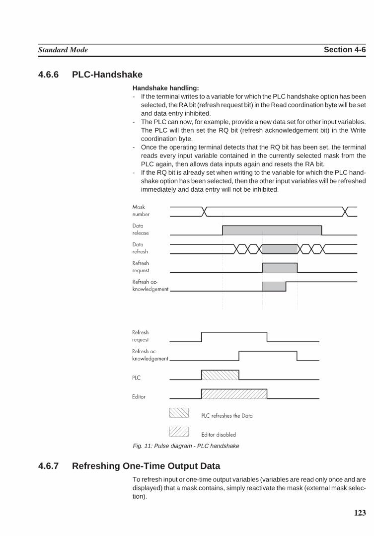
123
Standard Mode Section 4-6
4.6.6 PLC-HandshakeHandshake handling:- If the terminal writes to a variable for which the PLC handshake option has been
selected, the RA bit (refresh request bit) in the Read coordination byte will be setand data entry inhibited.
- The PLC can now, for example, provide a new data set for other input variables.The PLC will then set the RQ bit (refresh acknowledgement bit) in the Writecoordination byte.
- Once the operating terminal detects that the RQ bit has been set, the terminalreads every input variable contained in the currently selected mask from thePLC again, then allows data inputs again and resets the RA bit.
- If the RQ bit is already set when writing to the variable for which the PLC hand-shake option has been selected, then the other input variables will be refreshedimmediately and data entry will not be inhibited.
Fig. 11: Pulse diagram - PLC handshake
4.6.7 Refreshing One-Time Output DataTo refresh input or one-time output variables (variables are read only once and aredisplayed) that a mask contains, simply reactivate the mask (external mask selec-tion).
124
Standard Mode Section 4-6
4.6.8 Modified DataThe conditions that determine the transfer of modified data from the operating ter-minal to the controller are preset by the user in the variable definition. The followingoptions are available, allowing the user to select the point of time at which the dataare transferred:
- with the Enter key (standard)- with the +/- keys or the Enter key (Incremental Editor)- transfer continuously (upon modification), i.e. every intermediate status is trans-
ferred
In the Incremental Editor, every intermediate value is transferred.
The option to transfer continuously (upon every modification) is limited to valuesthat are within the defined limits. If a value is entered that is outside the upper andlower limit, the operator will get a system message to this effect.If a value with multiple digits is entered that - exceeds the upper limit
the digit entered most recently will not be transferred to the controller.
- falls below the lower limit,the previously valid value will be restored.
- falls below the lower limit (until the last digit has been entered) and then exceedsthe upper limit (after the last digit has been entered),the previously valid value will be restored.
4.6.8.1 Input Plausibility Check
The plausibility check is performed on every editable numerical variable. This re-quires that an upper and lower limit is specified in the variable definition. Theselimits are displayed in the corresponding output format. System messages aregenerated when invalid values are entered. Further guidance can be found in thechapters Editors and System Messages.
4.7 Graphics
4.7.1 ImagesAny program installed by the user can be used by the programming software as aserver for images.Images can principally be made use of in two ways:1.) Using existing images: The images created in another program can be se-
lected. A copy of the source image will then be stored in the project data-base and converted to a pixel graphics of the specified dimensions.
2.) Creating new images: The program to be used to create the new image canbe launched from within the programming system. Once the image hasbeen created, the server is exited and the image is stored in the projectdatabase. To display the image in the programming system and on the op-erating terminal, the image is converted into a pixel graphics of the specifieddimensions.
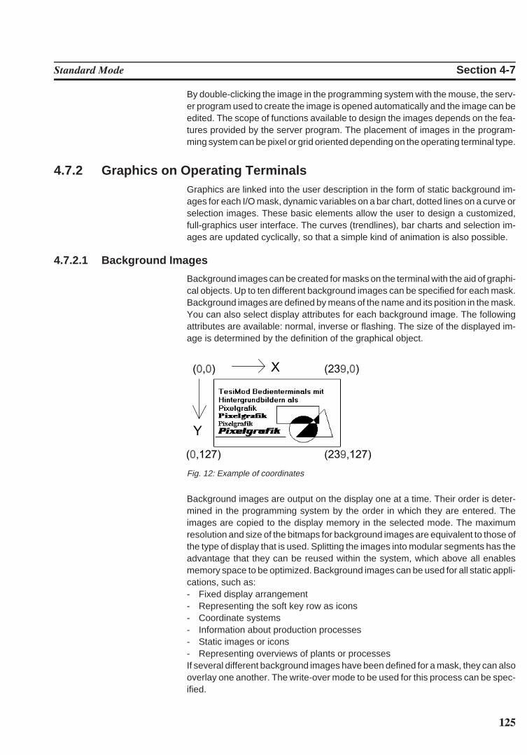
125
Standard Mode Section 4-7
By double-clicking the image in the programming system with the mouse, the serv-er program used to create the image is opened automatically and the image can beedited. The scope of functions available to design the images depends on the fea-tures provided by the server program. The placement of images in the program-ming system can be pixel or grid oriented depending on the operating terminal type.
4.7.2 Graphics on Operating TerminalsGraphics are linked into the user description in the form of static background im-ages for each I/O mask, dynamic variables on a bar chart, dotted lines on a curve orselection images. These basic elements allow the user to design a customized,full-graphics user interface. The curves (trendlines), bar charts and selection im-ages are updated cyclically, so that a simple kind of animation is also possible.
4.7.2.1 Background Images
Background images can be created for masks on the terminal with the aid of graphi-cal objects. Up to ten different background images can be specified for each mask.Background images are defined by means of the name and its position in the mask.You can also select display attributes for each background image. The followingattributes are available: normal, inverse or flashing. The size of the displayed im-age is determined by the definition of the graphical object.
Fig. 12: Example of coordinates
Background images are output on the display one at a time. Their order is deter-mined in the programming system by the order in which they are entered. Theimages are copied to the display memory in the selected mode. The maximumresolution and size of the bitmaps for background images are equivalent to those ofthe type of display that is used. Splitting the images into modular segments has theadvantage that they can be reused within the system, which above all enablesmemory space to be optimized. Background images can be used for all static appli-cations, such as:- Fixed display arrangement- Representing the soft key row as icons- Coordinate systems- Information about production processes- Static images or icons- Representing overviews of plants or processesIf several different background images have been defined for a mask, they can alsooverlay one another. The write-over mode to be used for this process can be spec-ified.
126
Standard Mode Section 4-8
4.8 RecipesVarious logically related variables can be organized into units known as recipes.Unlike mask variables, recipe variables are not transferred to the controller imme-diately after being entered, but are stored in the terminal as data sets. These datasets are protected against power failure. The data sets can be loaded to the con-troller as a unit as and when required.The maximum number of recipes that can be created at programming time is 250.For each recipe, up to 250 data sets can be created. The data sets can either becreated at programming time and be stored in the operating terminal’s Flash mem-ory together with the user description or can be entered online on the operatingterminal and are then stored in the battery-backed RAM. Data sets stored in theFlash memory must be copied to the RAM first before they can be edited. Data setsthat have been edited remain in the battery-backed RAM.
Example for the usage of recipes:Settings of a machine for manufacturing various products:
Variable Value UnitThe product clamp requires: Material ST37-3
Feedrate 25.00 mm/sSetpoint Value Axis 1 43.50 mmSetpoint Value Axis 2 56.30 mmCutting Angle 30 ˚Cutting Speed 110 mm/s
Variable Value UnitThe product shaft requires: Material X20Cr13
Feedrate 20.00 mm/sSetpoint Value Axis 1 45.60 mmSetpoint Value Axis 2 51.20 mmCutting Angle 45 ˚Cutting Speed 76 mm/s
The variables Material, Feedrate, Setpoint Value Axis 1, Setpoint Value Axis 2,Cutting Angle and Cutting Speed can be organized into the recipe ‘Machine Set-tings for Products’. The variables Feedrate, Setpoint Value Axis 1 and SetpointValue Axis 2 are defined as floating point numbers or fixed point numbers while thevariable Cutting Angle is defined as an integer and the variable Material as a selec-tion text.The values for manufacturing the products Clamp and Shaft must be stored as datasets. Whenever another product is to be manufactured, the data set of the productto be manufactured next can be loaded into the controller.The following check list contains all of the elements that are required and useful forcreating and handling a recipe with data sets:
127
Standard Mode Section 4-8
- The recipe itself (texts and variables)- Data sets with data set number, data set name and variable offset- I/O mask for the recipe- Recipe field in the mask- Recipe buffer (address for the data area in the controller)- Variable Data Set Number for Transfer from the Terminal- Variable Recipe Number for Transfer from the Terminal- Variable Data Set Number for Request from the Controller- Variable Recipe Number for Request from the Controller- System variables:
Variable Name Linkage Partner DescriptionSelectDSNr Selection Text/Decimal Number Display/Selection of the
Data Set NumberSelectDSName Selection Text Variable Display/Selection of the
Data Set NameDestDSNr Positive Decimal Number Destination Data Set Num-
ber for Copy ProcessDSCopy Soft Key/Selection Text Variable Activation of Data Set Copy
ProcessDSDelete Soft Key/Selection Text Variable Deletion of Data SetDSDownload Soft Key/Selection Text Variable Loading of Data Set to Con-
troller ActDSName Alphanumerical Variable Entering the Name for
RAM-Data SetSelectRezeptNr Selection Text/Decimal Number Display/Selection of the
Recipe NumberTabPgUp Soft Key Page upTabPgDn Soft Key Page downBreak Soft Key Cancel input
4.8.1 Structure of a RecipeA recipe comprises a maximum of 255 variables. In addition, up to 255 explanatorytexts can be programmed. The variables and texts can be spread out over a maxi-mum of 255 lines (with each line stretching across the entire width of the screen). Ahelp text can be programmed for every variable.The recipe is displayed in a recipe field, within an I/O mask, that extends over theentire width of the screen. The height of the recipe field can be as small as one lineor as large as the entire height of the screen. The Page up / Page down keys andthe cursor keys can be used to scroll through long recipes in the recipe field.All one-line formats and Editors that are available in I/O masks can also be used forrecipe variables. Multiple-line formats can not be used (for example, multiple-lineselection fields, tables, etc.). In addition, neither variables nor texts can be dis-played with the zoom option.
4.8.2 Processing Recipes and Data SetsThe majority of the operations described below refer to the active data set. In orderto activate a data set, first select the recipe to which it belongs and then the data setitself. How to select recipes and data sets is explained in the next two sections.
128
Standard Mode Section 4-8
4.8.2.1 Selecting a Recipe
All recipes are assigned a number from 1 to 250 when they are programmed.You can select a recipe as follows:
- By means of a fixed assignment between the recipe and a mask. Whenever thismask is opened, the recipe window will contain the recipe that was specified whenthe mask was originally programmed. If a fixed assignment to a recipe has notbeen defined when the mask with the recipe window was programmed, the lastrecipe that was processed appears in this window when the mask is opened.
- By means of the system variable SelectRezeptNr . This variable can be editedusing any Editor. It is a good idea, however, to use a selection text and assignmeaningful names to each recipe number.
4.8.2.2 Selecting a Data Set
Data sets can be assigned both a number from 1 to 250 and a name.The data set numbers and names are allocated when the data sets are created, inother words either in the programming system for data sets stored in the Flashmemory or on the terminal in the case of data sets stored in the RAM. The maxi-mum data set name length is 15 characters. Data set names need not necessarilybe unique (though it is recommended that they are).
A data set can be selected in one of the following ways:- By selecting a new recipe. The associated data set with the lowest number is
then selected for it automatically.
- By means of the system variable SelectDSNr . This variable can only be editedas a selection text. In this case, only the numbers of those data sets that areavailable for the active recipe are displayed.
- By means of the system variable SelectDSName . This variable can only beedited as a selection text. In this case, only the names of those data sets that areavailable for the active recipe are displayed.
4.8.2.3 Copying a Data Set
Only the active data set can be copied. To do so, the number of the destination dataset is written to the system variable DestDSNr and then the value 1 to the systemvariable DSCopy . The following conditions must be fulfilled in order for the data set to be copiedsuccessfully:- The number of the destination data set must be between 1 and 250 (DSCopy = 2
searches for a free data set, while DSCopy = 3 overwrites the existing data set).- There must not already be a data set with the same number for the active recipe
(unless DSCopy is set to 3).- The active data set can not be edited at the same time.- There must be enough free RAM on the terminal.
If any of these conditions is not satisfied, the data set is not copied and a systemerror message is output.
129
Standard Mode Section 4-8
The destination data set becomes the active data set after it has been copied.
After it has been copied, the name of the destination data set consists merely ofblanks. A new name can be defined with the system variable ActDSName .
4.8.2.4 Deleting a Data Set
Only the active data set can be deleted. To do so, the value 1 is written to thesystem variable DSDelete . The following conditions must be fulfilled in order for the data set to be deletedsuccessfully:- The active data set can not be edited at the same time.- The data set must be stored in the RAM.
If any of these conditions is not satisfied, the data set is not deleted and a systemerror message is output.
After the deletion, the data set with the lowest number in the current recipebecomes the active data set.
4.8.2.5 Modifying a Data Set
The active data set can be modified, providing it is stored in the RAM. To change the contents of a data set, the variables must be edited in the recipewindow. Note, however, that the new values are not written in the data set as soonas the Enter key is pressed, but are first stored in a temporary buffer. The DataRelease key must then be pressed in order to accept them. If the new values are notto be accepted, the system variable Break can be set to 1 to discard the contents ofthe buffer. It is a good idea to program one of the soft keys to this variable, in order tosave time.
Another data set can not be selected until the buffer contents has either beenaccepted or discarded.
If the controller changes to a different mask while a data set is being modified, or ifthe external data release is cancelled again before the Data Release key ispressed, the buffer contents will likewise be discarded.The modified data set is not transferred to the controller automatically. An explicitcommand from the operator or the controller is necessary first.
4.8.3 Data Set Transfer to / from a Controller
4.8.3.1 Transfer to a Controller
A data set can be transferred to the controller in the following ways:- The active data set can be transferred to the controller by setting the system
variable DSDownload to 1.- The controller can issue a request for any data set. It first sets the variable
addresses for the recipe and data set numbers to the required values. It thenwrites the value 7FFBH to the address of the serial signaling channel (see sec-tion 4.22 Cyclic Poll Area).
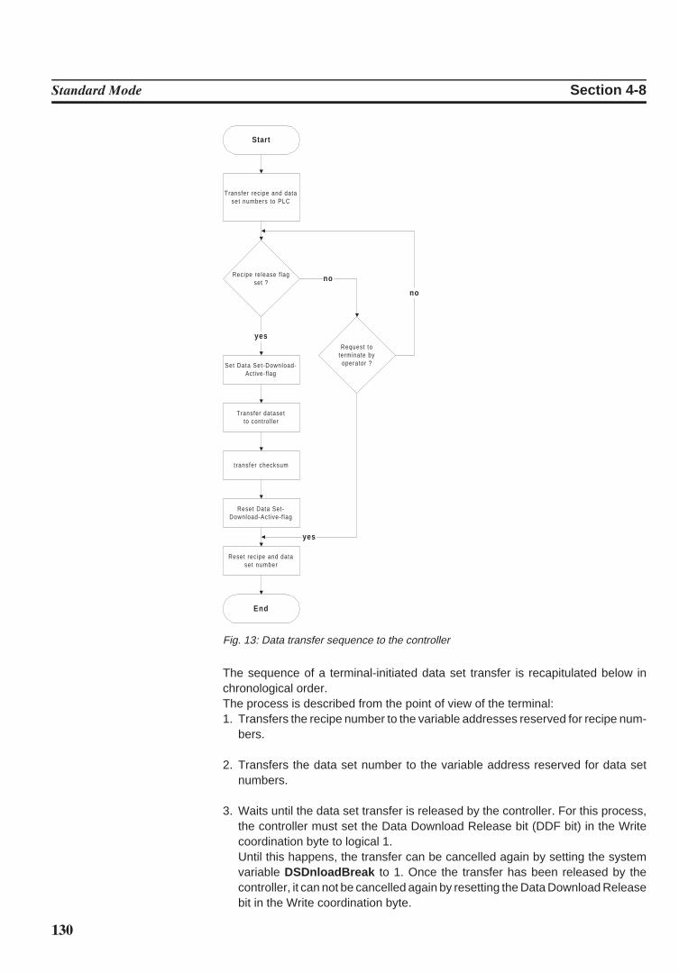
130
Standard Mode Section 4-8
Start
Transfer recipe and dataset numbers to PLC
Recipe release f lagset ?
Set Data Set-Download-Active-f lag
Transfer datasetto control ler
t ransfer checksum
Reset Data Set-Download-Act ive-f lag
Reset recipe and dataset number
End
Request toterminate by
operator ?
no
yes
no
yes
Fig. 13: Data transfer sequence to the controller
The sequence of a terminal-initiated data set transfer is recapitulated below inchronological order.The process is described from the point of view of the terminal:1. Transfers the recipe number to the variable addresses reserved for recipe num-
bers.
2. Transfers the data set number to the variable address reserved for data setnumbers.
3. Waits until the data set transfer is released by the controller. For this process,the controller must set the Data Download Release bit (DDF bit) in the Writecoordination byte to logical 1.Until this happens, the transfer can be cancelled again by setting the systemvariable DSDnloadBreak to 1. Once the transfer has been released by thecontroller, it can not be cancelled again by resetting the Data Download Releasebit in the Write coordination byte.
131
Standard Mode Section 4-8
4. Sets the Data Download Active bit in the Read coordination byte.This bit can be used by the controller to identify an incomplete data set transfer(communication interrupted, power failure). An incomplete transfer is, however,repeated the next time the terminal is booted.
5. Transfers the data set to the recipe buffer defined in the controller. A separaterecipe buffer can be programmed for each recipe. The recipe buffer must be atleast one byte larger than the data set (on account of the checksum) and consistof an even number of bytes (in other words, an extra byte must be added ifnecessary).
6. Transfers the checksum. The byte-wise XOR checksum (for the complete dataset) is written to the address that follows the last byte of the data set. It providesthe controller with additional protection against errors caused by incompletelytransferred data sets.
7. Resets the Data Download Active bit in the Read coordination byte.
8. Resets the recipe and data set numbers to the variables that have been pro-grammed in the controller for this purpose. The recipe number is set to 0 and thedata set number to 255.
The various steps in this process can be monitored by the operator with the aid ofthe system variable DSDnloadState .The name of the last data set to have been loaded in the controller is stored in theterminal for each recipe. This name can be displayed for the active recipe with thesystem variable LoadDSName . If a data set has not yet been loaded in the controll-er for this recipe, or if the data set which was loaded in the controller has alreadybeen deleted, a question mark appears on the display instead.
4.8.3.2 Transfer from a Controller
Certain applications may require that individual data set values in the controller aremodified (for example, teaching) and that the modified data set is transferred backto the operating terminal. An option to transfer data sets from the controller to theterminal has therefore been provided.A data set can be transferred from the controller to the terminal in either of thefollowing ways:- By writing a value to the system variable StartUpload to initiate a data set read
process for the active recipe. If the value 1 is written to the system variable, thevariables will be read individually from the addresses specified during variableprogramming. If the value 2 is written to the system variable, the variables will beread as a block from the data set buffer defined for the recipe. The number underwhich the data set is to be stored in the terminal can be specified via the systemvariable UploadDSNr . The default setting for this system variable is 0. If a desti-nation data set number is not entered, the transferred data set will temporarilybe stored under the number 0 and will then have to be copied to a valid number(1-250).
132
Standard Mode Section 4-8
- The PLC issues a request for a data set read process. For this process, thecontroller writes the recipe number and data set number (the same as those forthe transfer to the controller on request by the controller) of the destination dataset to the variable specified for this purpose. Subsequently, one of the messagenumbers
7FFDH (variables are read from their specified addresses individually) or7FFAH (variables are read from the defined data set buffer as a block)
must be transferred. After the data have been transferred successfully, the rec-ipe number is overwritten with 0. If there is no more free memory available in theoperating terminal or if the specified data set number already exists in the Flashmemory, the recipe number will be overwritten with 255. The data set numberwill not be overwritten in either case.
If the newly read data set overwrites a data set that already exists in the RAM withthe same number, its name will be used for the newly read data set. If a data setdoes not yet exist with that number, the name will merely consist of blanks.
The read process can be monitored by the operator with the aid of the systemvariable UploadState .
4.8.4 Transferring Data Sets to / from a PCIt is possible to transfer data sets to or from a PC via SER2, in order to back up thedata sets that have been stored in the terminal, process the data or supply theterminal with new data sets.It is also particularly important to back up the data sets if a new user description isloaded in the terminal, as all the data sets in the RAM are then deleted. If the recipestructure remains unchanged, however, they can be reloaded into the terminalagain after the user description has been loaded. If changes have been made to thestructure of any of the recipes (number of variables, position of the variables in thedata set buffer, etc.), only the data sets of the other, unchanged recipes can bereloaded into the terminal.The data sets are transferred in a format that can be edited using a Text Editor (seesection 4.8.4.3 Structure of the Data Set File).The parameters for the interface channel SER2 can be freely configured by meansof the corresponding system variables. Merely make sure that the same para-meters are set at the PC end. You can send or receive at the PC end with anysuitable program, such as Windows Terminal (1).
4.8.4.1 Transfer to a PC
The transfer of data sets to the PC is initiated by writing a value to the systemvariable StartSave . The number of data sets that are transferred depends on thevalue that is written to the system variable. The following are valid values:System variable value = 1: Only the active data set is transferred.System variable value = 2: All of the data sets of the active recipe are transferred.System variable value = 3: All of the data sets of all recipes are transferred.
The process can be monitored by the operator with the aid of the system variableSaveState .
133
Standard Mode Section 4-8
4.8.4.2 Transfer from a PC
The terminal is placed to the Ready-to-Receive state when the system variableStartRestore is set to 1. The data sets can then be sent by the PC. The terminalrecognizes the end of the data set transfer automatically by analyzing the data ithas received. It then returns to its normal state.To cancel the Ready-to-Receive state again without receiving data, the value of thesystem variable StartRestore must be changed to 2.The system variable RestoreState indicates whether or not the terminal is ready toreceive.If a formatting error is detected in the received data, a system message to this effectis output and the receive process is terminated. The position of the formatting errorcan be localized, at least approximately, with the aid of the system variable Re-storeLineNr . This variable contains the number of the last line to have been re-ceived.Data sets can only be stored in the terminal if their structure is still identical to thedata set structure specified for the recipe concerned in the user description. Thiscan be checked by the terminal on the basis of a version number (see Structure ofData Set File). If a data set which is found to be invalid is received, it is rejected anda system message to this effect is output. The receive process is not terminated,however.If a data set with the same number as the transferred data set is already stored inthe Flash-Eprom, the newly received data set is rejected without any warning to theoperator.If a data set with the same number as the transferred data set is already stored inthe RAM, a parameter setting in the received data (see Structure of Data Set File)determines whether or not the existing data set is overwritten. If it is not supposed tobe overwritten, and another data set with the same number already exists in theterminal, the newly received data set is similarly rejected without any warning to theoperator.
4.8.4.3 Structure of a Data Set File
The data sets transferred to the PC are generally stored in a file.If this file is only used for backup purposes, the operator does not necessarily befamiliar with its structure. In this case, the file can merely be transferred back to theterminal unchanged when it is needed.If the data are to be processed further, for example, within the scope of productiondata acquisition, the operator should understand the structure of the file.All of the data in the data set file are represented by a simple language specificallydeveloped for this purpose.
134
Standard Mode Section 4-8
The following are elements of this language:
Key words: S + two further letters. They normally appear at thebeginning of a line.
Example: SDW or SFADecimal number: Any number of the digits 0-9, preceded by a negative
sign when required.Example: 999 or -1234567
Hexadecimal number: H + any number of the digits 0-9 or letters A-F or a-f.Example: H999 or H123abCD4
Hexadecimal string: C + any even number of the digits 0-9 or letters A-F ora-f.
Example: C12 or CAAFF33ASCII string: Any string of characters enclosed between two back-
slash characters (\) .Example: \This is one ASCII string\
Comment: Any string of characters enclosed between two dollarsigns ($). Comments can be inserted in the data setbackup file at any position and can stretch acrossseveral lines.
Example: $This is a comment$
Any number of separators (blanks, tab characters or line feed characters) can beplaced between these language elements.
The above-mentioned language elements are used to create a file with the follow-ing structure:- Start of file identifier- Any number of data sets- End of file identifier
A data set consists of:- Data set header- Any number of data set variables- End of data set identifier
Start of file identifier:Key: SFAParameters: none (date and time are output by the terminal as a comment)
End of file identifier:Key: SFEParameters: none
Data set header:Key: SDKParameters: Recipe number, data set number, data set name (as an ASCII string),data set size in bytes, recipe version number, write-over identifier
135
Standard Mode Section 4-8
Data set variables:Key: SDWParameters: Offset of the variables in the recipe, variable size in bytes, value of thevariables (as a hexadecimal string)
End of data set identifier:Key: SDEParameters: none
Explanations:Recipe Version Number:On creating or changing the recipe description in the programming system, thisversion number is increased automatically whenever the structure of the data setshas changed. To be able to load a data set from the PC to the operating terminal,the downloaded version number and the version number stored in the operatingterminal for the recipe involved must match. The downloaded data set will not bestored if they do not match.Write-over identifier:The value 1 means that the downloaded data set is to overwrite any data set withthe same number that may already exist in the operating terminal. The value 0means that the downloaded set is to be rejected if a data set with the same numberalready exists. Only those data sets can be overwritten that are not stored in theFlash memory, i.e. that were loaded into the terminal together with the user de-scription.
4.8.5 Printing Data SetsThe data set printout can be started from both the operating terminal and the con-troller.To be able to initiate a printout from the operating terminal, either the system var-iable StartRezPrint must be placed into a mask or a soft key must be assignedaccordingly. The active data set can be printed via SER2 by writing the value 1 tothe system variable.
Writing the value 2 to the same system variable will cancel the print process.A heading including the recipe number, data set number and data set name will beprinted at the beginning of each data set.The status of the print process can be indicated via the system variable RezPrint-State .
To be able to control a print job from the controller, the data set number and recipenumber must be entered into the appropriate variables first. The print job is thenstarted by writing the value 7FF8H to the address of the serial message channel. Avalue of 0 (zero) in the variable for the recipe number (for request from the terminal)will indicate that the data set is being printed.If another print job is currently being printed so that the printer can not print thespecified data set, the value 255 will be written to the variable for the recipe number(for request from the terminal).
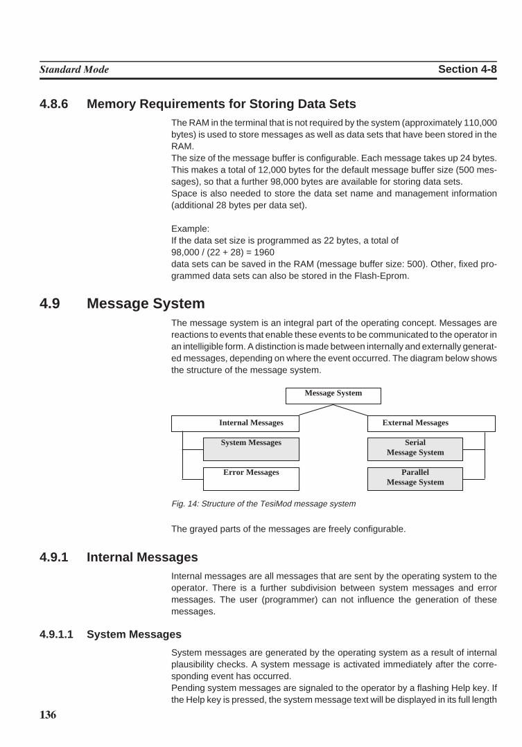
136
Standard Mode Section 4-8
4.8.6 Memory Requirements for Storing Data SetsThe RAM in the terminal that is not required by the system (approximately 110,000bytes) is used to store messages as well as data sets that have been stored in theRAM. The size of the message buffer is configurable. Each message takes up 24 bytes.This makes a total of 12,000 bytes for the default message buffer size (500 mes-sages), so that a further 98,000 bytes are available for storing data sets.Space is also needed to store the data set name and management information(additional 28 bytes per data set).
Example:If the data set size is programmed as 22 bytes, a total of 98,000 / (22 + 28) = 1960 data sets can be saved in the RAM (message buffer size: 500). Other, fixed pro-grammed data sets can also be stored in the Flash-Eprom.
4.9 Message SystemThe message system is an integral part of the operating concept. Messages arereactions to events that enable these events to be communicated to the operator inan intelligible form. A distinction is made between internally and externally generat-ed messages, depending on where the event occurred. The diagram below showsthe structure of the message system.
Message System
Internal Messages External Messages
System Messages SerialMessage System
Error Messages ParallelMessage System
Fig. 14: Structure of the TesiMod message system
The grayed parts of the messages are freely configurable.
4.9.1 Internal MessagesInternal messages are all messages that are sent by the operating system to theoperator. There is a further subdivision between system messages and errormessages. The user (programmer) can not influence the generation of thesemessages.
4.9.1.1 System Messages
System messages are generated by the operating system as a result of internalplausibility checks. A system message is activated immediately after the corre-sponding event has occurred.Pending system messages are signaled to the operator by a flashing Help key. Ifthe Help key is pressed, the system message text will be displayed in its full length
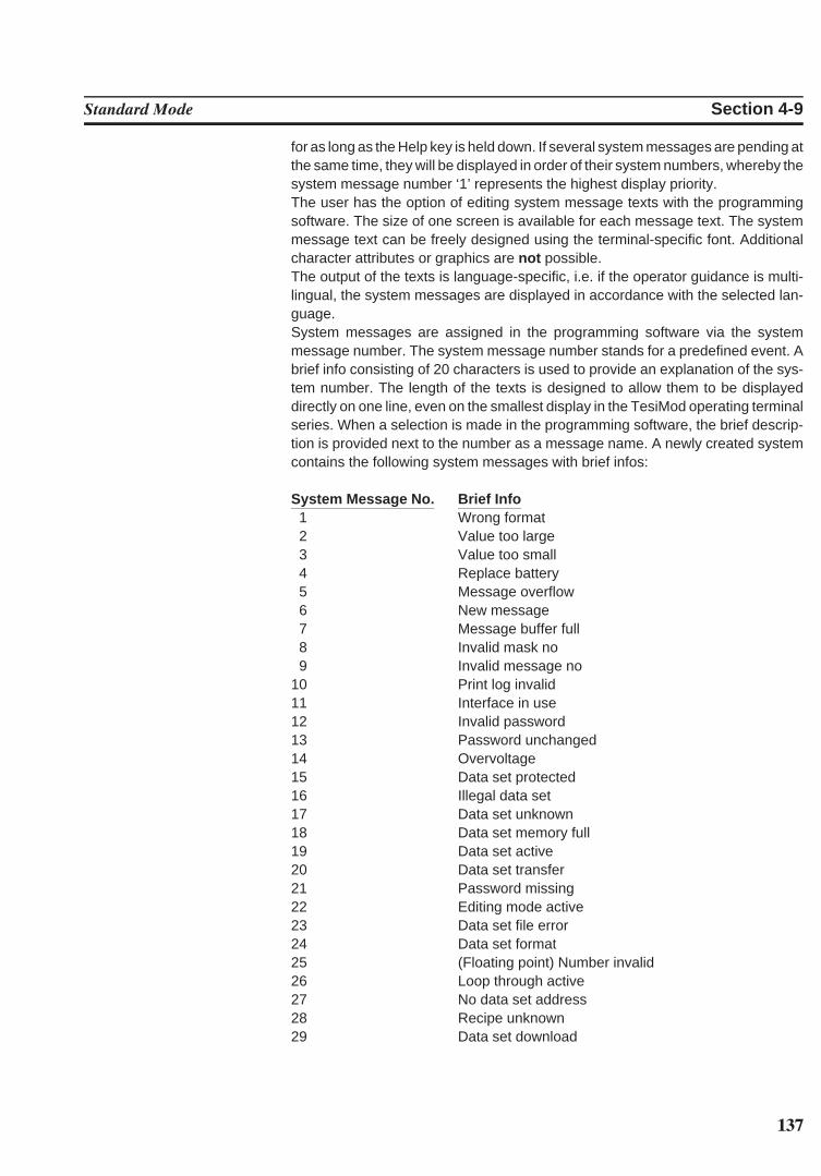
137
Standard Mode Section 4-9
for as long as the Help key is held down. If several system messages are pending atthe same time, they will be displayed in order of their system numbers, whereby thesystem message number ‘1’ represents the highest display priority.The user has the option of editing system message texts with the programmingsoftware. The size of one screen is available for each message text. The systemmessage text can be freely designed using the terminal-specific font. Additionalcharacter attributes or graphics are not possible.The output of the texts is language-specific, i.e. if the operator guidance is multi-lingual, the system messages are displayed in accordance with the selected lan-guage.System messages are assigned in the programming software via the systemmessage number. The system message number stands for a predefined event. Abrief info consisting of 20 characters is used to provide an explanation of the sys-tem number. The length of the texts is designed to allow them to be displayeddirectly on one line, even on the smallest display in the TesiMod operating terminalseries. When a selection is made in the programming software, the brief descrip-tion is provided next to the number as a message name. A newly created systemcontains the following system messages with brief infos:
System Message No. Brief Info1 Wrong format2 Value too large3 Value too small4 Replace battery5 Message overflow6 New message7 Message buffer full8 Invalid mask no9 Invalid message no
10 Print log invalid11 Interface in use12 Invalid password13 Password unchanged14 Overvoltage15 Data set protected16 Illegal data set17 Data set unknown18 Data set memory full19 Data set active20 Data set transfer21 Password missing22 Editing mode active23 Data set file error24 Data set format25 (Floating point) Number invalid26 Loop through active27 No data set address28 Recipe unknown29 Data set download
138
Standard Mode Section 4-9
System Message 1 . . . . .‘Wrong format’This text indicates that an attempt has been made to enter an invalid data formatinto a variable field of the Numerical Editor. For example, the number of pre-deci-mal places entered exceeds the setting specified in the user description.
System Message 2 . . . . .‘Value too large’This indicates that an attempt has been made to enter a value into a variable field ofthe Editor that exceeds the variable’s upper limit. The upper limit is defined in theuser description. If the text is deleted from the system message, no system mes-sage will be displayed if a value is entered that is too large. In this case, the maxi-mum value that is valid is entered instead.
System Message 3 . . . . .‘Value too small’This indicates that an attempt has been made to enter a value into a variable field ofthe Editor that falls below the variable’s lower limit. The lower limit is defined in theuser description. If the text is deleted from the system message, no system mes-sage will be displayed if a value is entered that is too small. In this case, the mini-mum value that is valid is entered instead.
System Message 4 . . . . .‘Replace battery’This text is displayed when a test performed on the battery indicates that its capac-ity has fallen below the limit values. This capacity test is repeated every 60 minutes.To retain the recipe data and the data stored in the message memory, the batterymust be replaced within 2-3 days of initial display of this message. To avoid loss ofdata when replacing the battery, the information in the chapter 1.9 Battery must becomplied with. The same message appears when the battery is removed, switch-ing the terminal off at this point will, however, result in the battery-backed databeing lost.
System Message 5 . . . . .‘Message overflow’This text indicates that the system is unable to process the external messagesquickly enough. Upon display of this message, one message has already beenlost.
System Message 6 . . . . .‘New message’This text is displayed when the Help key is pressed and the terminal has received anew external message whose priority exceeds the programmed threshold valueand no direct selector key has been assigned to the message mask.
System Message 7 . . . . .‘Message buffer full’This text is displayed as a warning that the next external messages may overwritethe oldest or lowest-priority messages (depending on the configuration).
System Message 8 . . . . .‘Invalid mask no’This text is displayed to indicate that a non-existing mask number has been trans-mitted by the PLC via the serial message channel.
System Message 9 . . . . .‘Invalid message no’This text indicates that the PLC has attempted to activate a non-existing messagenumber.
System Message 10 . . . .‘Print log invalid’The operator or the PLC has attempted to activate a non-existing print log.
139
Standard Mode Section 4-9
System Message 11 . . . .‘Interface in use’SER2 is already being used by another print job. An attempt has been made totransmit different types of data to the printer at the same time (e.g. to print recipesand messages).
System Message 12 . . . .‘Invalid Password’The operator has entered a password which does not exist in the password list.With this message, the previous access authorizations (view and edit level) arereset.
System Message 13 . . . .‘Password unchanged’The operator did not enter the same new password two times in a role.
System Message 14 . . . .‘Overvoltage’The system has detected that the supply voltage is too high. Switch the terminal offimmediately to avoid damage. Check supply voltage.
System Message 15 . . . .‘Data set protected’An attempt has been made to modify individual values of a data set stored in theflash or to delete the entire data set.
System Message 16 . . . .‘Illegal data set’The data set number specified as the destination for the data set copy processexists already or is outside the valid range (for example, flash).
System Message 17 . . . .‘Data set unknown’A data set has been selected whose number does not exist in the data set list.
System Message 18 . . . .‘Data set memory full’An attempt has been made to create a new data set, but the data set memory is full.
System message 19 . . . .‘Data set active’An attempt has been made to erase or to copy to the active data set or to select adata set even though the active data set is currently being edited.
System Message 20 . . . .‘Data set transfer’An attempt has been made to initiate a data set transfer to the controller eventhough the previously initiated transfer has not yet been completed.
System Message 21 . . . .‘Password missing’An attempt has been made to switch to a password-protected mask or to edit apassword-protected mask without having entered a password with sufficient au-thorization.
System Message 22 . . . .‘Editing mode active’An attempt has been made to perform a change of mask while the terminal was inthe editing mode.
System Message 23 . . . .‘Data set file error’The data set file loaded from the PC to the terminal contains a syntax error. Theerror can be localized by means of the line number system variable.
140
Standard Mode Section 4-9
System Message 24 . . . .‘Data set format’The size or internal version identifier of a data set loaded from the PC to the terminaland the corresponding values in the programming software do not match.
System Message 25 . . . .‘(Floating point) Number invalid’The bit pattern read from the controller is not valid for a floating point number. Thenumber is displayed as 0.0.
System Message 26 . . . .‘Loop-through active’The selected action was not performed due to an active loop-through operation.
System Message 27 . . . .‘No data set address’The addresses for the data set transfer did not exist at the time of the controller’srequest.
System Message 28 . . . .‘Recipe unknown’An attempt has been made to select a recipe that does not exist in the terminal.
System Message 29 . . . .‘Data set download’A data set transfer to the controller (download) has been initiated, but the Data SetDownload Release bit in the Write coordination byte (bit 4) has not yet been set bythe controller.
4.9.1.1.1 Suppressing the Display of System Messages
The operating concept provides you the option of suppressing the display of sys-tem messages. The display of a system message can be prevented by erasing thesystem message in the programming software.
Example:System message 7 ‘Message buffer full’ is to be suppressed. Older messages ormessages with a lower priority are to be overwritten.The system message text in the programming software is erased.By suppressing the display of this system message, the user agrees that incomingmessages automatically overwrite the oldest messages or those with the lowestpriority once the message buffer is full.
4.9.1.2 Error Messages
The messages listed below are displayed by the operating system. The messagetexts are part of the operating system and are displayed in English. The size of thetexts has been chosen in such a way that they can be displayed on every terminal.The output of these texts can not be suppressed and their contents can not bemodified. The term ‘error message’ is used because the terminal does not operatein accordance with the true meaning of the TesiMod standard mode while thesemessages are displayed. In addition to true system errors, various conditions andprocesses are also described.
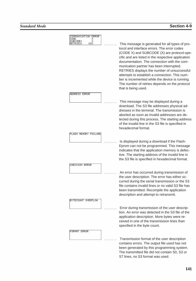
141
Standard Mode Section 4-9
. . . . . . . . This message is generated for all types of pro-tocol and interface errors. The error codes(CODE X) and SUBCODE (X) are protocol-spe-cific and are listed in the respective applicationdocumentation. The connection with the com-munication partner has been interrupted.RETRIES displays the number of unsuccessfulattempts to establish a connection. This num-ber is incremented while the device is running.The number of retries depends on the protocolthat is being used.
. . . . . . . . This message may be displayed during adownload. The S3 file addresses physical ad-dresses in the terminal. The transmission isaborted as soon as invalid addresses are de-tected during this process. The starting addressof the invalid line in the S3 file is specified inhexadecimal format.
. . . . . . . . Is displayed during a download if the Flash-Eprom can not be programmed. This messageindicates that the application memory is defec-tive. The starting address of the invalid line inthe S3 file is specified in hexadecimal format.
. . . . . . . . An error has occurred during transmission ofthe user description. The error has either oc-curred during the serial transmission or the S3file contains invalid lines or no valid S3 file hasbeen transmitted. Recompile the applicationdescription and attempt to retransmit.
. . . . . . . . Error during transmission of the user descrip-tion. An error was detected in the S3 file of theapplication description. More bytes were re-ceived in one of the transmission lines thanspecified in the byte count.
. . . . . . . . Transmission format of the user descriptioncontains errors. The output file used has notbeen generated by this programming system.The transmitted file did not contain S0, S3 orS7 lines, no S3 format was used.
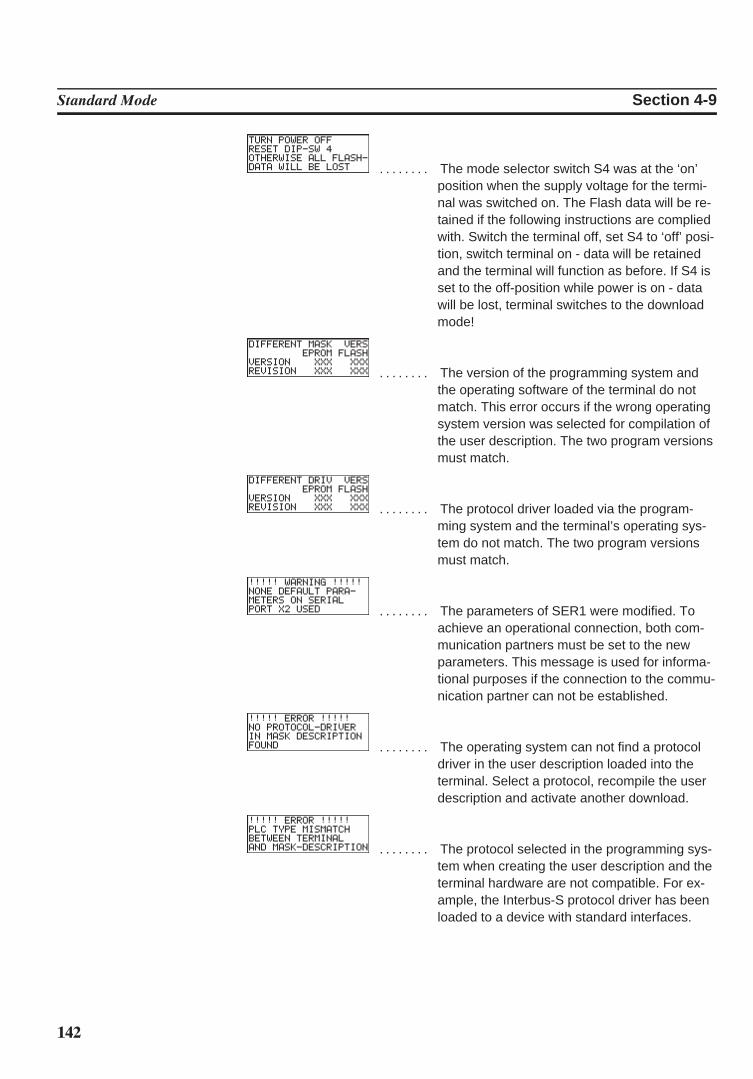
142
Standard Mode Section 4-9
. . . . . . . . The mode selector switch S4 was at the ‘on’position when the supply voltage for the termi-nal was switched on. The Flash data will be re-tained if the following instructions are compliedwith. Switch the terminal off, set S4 to ‘off’ posi-tion, switch terminal on - data will be retainedand the terminal will function as before. If S4 isset to the off-position while power is on - datawill be lost, terminal switches to the downloadmode!
. . . . . . . . The version of the programming system andthe operating software of the terminal do notmatch. This error occurs if the wrong operatingsystem version was selected for compilation ofthe user description. The two program versionsmust match.
. . . . . . . . The protocol driver loaded via the program-ming system and the terminal’s operating sys-tem do not match. The two program versionsmust match.
. . . . . . . . The parameters of SER1 were modified. Toachieve an operational connection, both com-munication partners must be set to the newparameters. This message is used for informa-tional purposes if the connection to the commu-nication partner can not be established.
. . . . . . . . The operating system can not find a protocoldriver in the user description loaded into theterminal. Select a protocol, recompile the userdescription and activate another download.
. . . . . . . . The protocol selected in the programming sys-tem when creating the user description and theterminal hardware are not compatible. For ex-ample, the Interbus-S protocol driver has beenloaded to a device with standard interfaces.
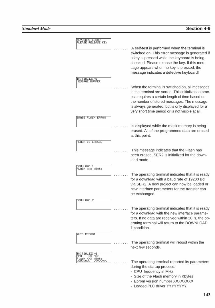
143
Standard Mode Section 4-9
. . . . . . . . A self-test is performed when the terminal isswitched on. This error message is generated ifa key is pressed while the keyboard is beingchecked. Please release the key. If this mes-sage appears when no key is pressed, themessage indicates a defective keyboard!
. . . . . . . . When the terminal is switched on, all messagesin the terminal are sorted. This initialization proc-ess requires a certain length of time based onthe number of stored messages. The messageis always generated, but is only displayed for avery short time period or is not visible at all.
. . . . . . . . Is displayed while the mask memory is beingerased. All of the programmed data are erasedat this point.
. . . . . . . . This message indicates that the Flash hasbeen erased. SER2 is initialized for the down-load mode.
. . . . . . . . The operating terminal indicates that it is readyfor a download with a baud rate of 19200 Bdvia SER2. A new project can now be loaded ornew interface parameters for the transfer canbe exchanged.
. . . . . . . . The operating terminal indicates that it is readyfor a download with the new interface parame-ters. If no data are received within 20 s, the op-erating terminal will return to the DOWNLOAD1 condition.
. . . . . . . . The operating terminal will reboot within thenext few seconds.
. . . . . . . . The operating terminal reported its parametersduring the startup process:- CPU frequency in MHz- Size of the Flash memory in Kbytes- Eprom version number XXXXXXXX- Loaded PLC driver YYYYYYYY
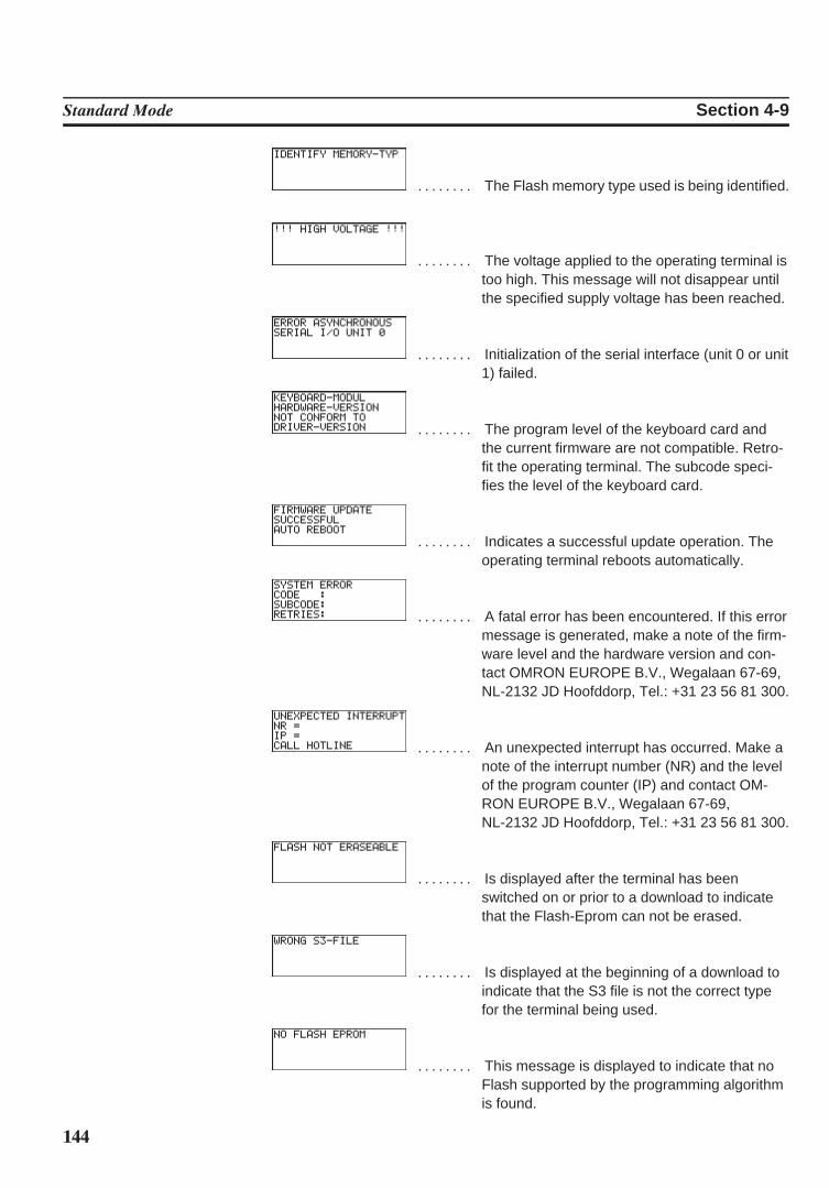
144
Standard Mode Section 4-9
. . . . . . . . The Flash memory type used is being identified.
. . . . . . . . The voltage applied to the operating terminal istoo high. This message will not disappear untilthe specified supply voltage has been reached.
. . . . . . . . Initialization of the serial interface (unit 0 or unit1) failed.
. . . . . . . . The program level of the keyboard card andthe current firmware are not compatible. Retro-fit the operating terminal. The subcode speci-fies the level of the keyboard card.
. . . . . . . . Indicates a successful update operation. Theoperating terminal reboots automatically.
. . . . . . . . A fatal error has been encountered. If this errormessage is generated, make a note of the firm-ware level and the hardware version and con-tact OMRON EUROPE B.V., Wegalaan 67-69,NL-2132 JD Hoofddorp, Tel.: +31 23 56 81 300.
. . . . . . . . An unexpected interrupt has occurred. Make anote of the interrupt number (NR) and the levelof the program counter (IP) and contact OM-RON EUROPE B.V., Wegalaan 67-69,NL-2132 JD Hoofddorp, Tel.: +31 23 56 81 300.
. . . . . . . . Is displayed after the terminal has beenswitched on or prior to a download to indicatethat the Flash-Eprom can not be erased.
. . . . . . . . Is displayed at the beginning of a download toindicate that the S3 file is not the correct typefor the terminal being used.
. . . . . . . . This message is displayed to indicate that noFlash supported by the programming algorithmis found.
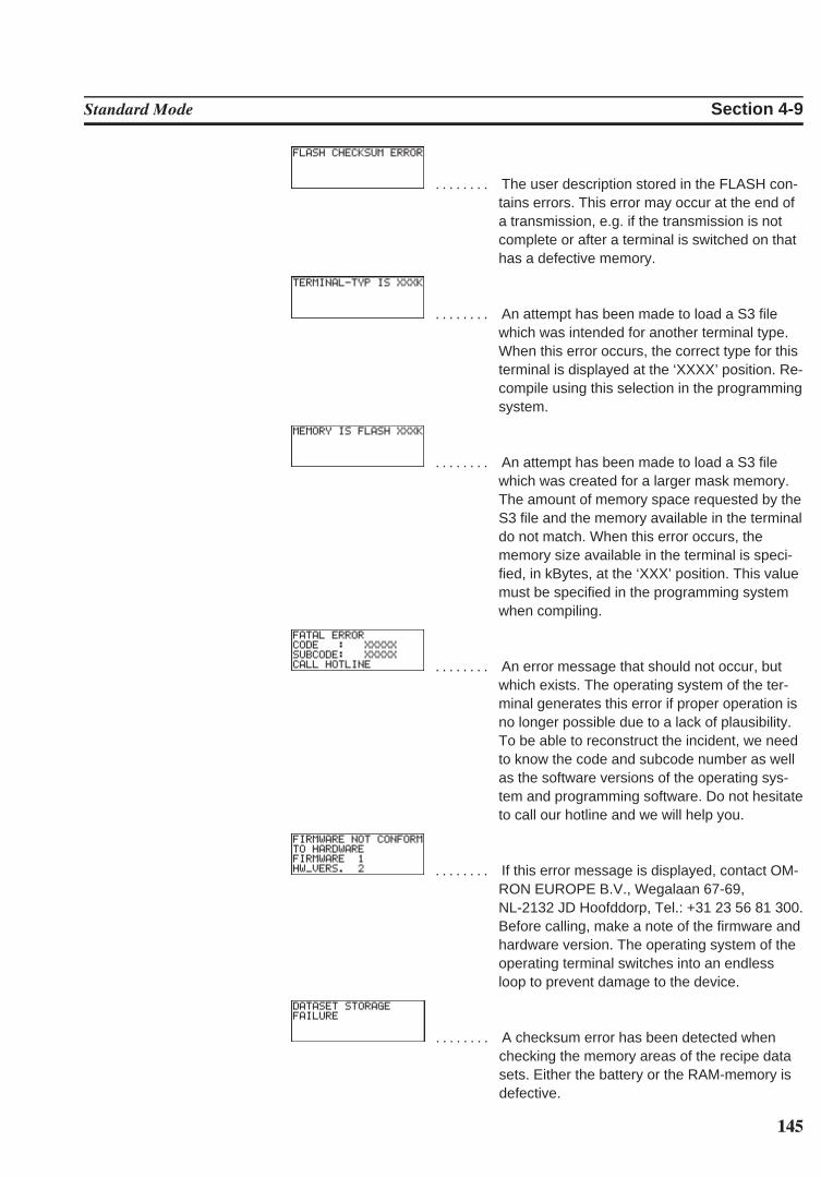
145
Standard Mode Section 4-9
. . . . . . . . The user description stored in the FLASH con-tains errors. This error may occur at the end ofa transmission, e.g. if the transmission is notcomplete or after a terminal is switched on thathas a defective memory.
. . . . . . . . An attempt has been made to load a S3 filewhich was intended for another terminal type.When this error occurs, the correct type for thisterminal is displayed at the ‘XXXX’ position. Re-compile using this selection in the programmingsystem.
. . . . . . . . An attempt has been made to load a S3 filewhich was created for a larger mask memory.The amount of memory space requested by theS3 file and the memory available in the terminaldo not match. When this error occurs, thememory size available in the terminal is speci-fied, in kBytes, at the ‘XXX’ position. This valuemust be specified in the programming systemwhen compiling.
. . . . . . . . An error message that should not occur, butwhich exists. The operating system of the ter-minal generates this error if proper operation isno longer possible due to a lack of plausibility.To be able to reconstruct the incident, we needto know the code and subcode number as wellas the software versions of the operating sys-tem and programming software. Do not hesitateto call our hotline and we will help you.
. . . . . . . . If this error message is displayed, contact OM-RON EUROPE B.V., Wegalaan 67-69,NL-2132 JD Hoofddorp, Tel.: +31 23 56 81 300.Before calling, make a note of the firmware andhardware version. The operating system of theoperating terminal switches into an endlessloop to prevent damage to the device.
. . . . . . . . A checksum error has been detected whenchecking the memory areas of the recipe datasets. Either the battery or the RAM-memory isdefective.
146
Standard Mode Section 4-9
4.9.2 External MessagesExternal messages are generated by the connected controller and forwarded to theoperating terminal as information on the monitored process. The user can choosetwo separate message systems. Depending on the requirements, message trans-fers to the operating terminal can be either serial or parallel, regardless of whetherthe messages are process or fault messages.
Messages can consist of the message text and a scaled and formatted variable.Every variable type available in the system is valid.
The information in the message memory can be used for statistical evaluations.The message is assigned between the terminal and the controller by means of amessage number. The associated texts and variable specifications are stored inthe terminal together with the user description. The function of a message and itscontents are determined by the user when the user description is created in theprogramming system.
All of the external messages are stored in the message memory in chronologicalorder or in order of priority. In addition parallel messages can optionally be stored inthe serial message memory and as a result also evaluated statistically. If the mess-age contains a variable, its value will be frozen in the message memory.
4.9.2.1 Structure of an External Message
An external message is made up of:- a message number between 1 and 9999- a message text with up to 255 characters- one variable at maximum.When creating a new application, existing messages (one or all) are reusable.
4.9.2.1.1 Assigning Message Numbers
With external messages, message numbers also determine the priority of a mes-sage, with message no. 1 being the highest and message no. 9999 being the low-est priority. It is not necessary that message numbers are assigned contiguously;this allows messages with related contents to be grouped.The assignment of message numbers for status messages always starts with ‘1’.Make sure that the serial and parallel message system do not overlap. If the twomessage systems are to be independent from one another, ensure that the mes-sage numbers for the serial system start above those for the status messages. Inaddition, message numbers and mask numbers must be coordinated accordinglywhen the programming is carried out (see chapter 4.9.2.3.1 Full-Page MessageOutput).The system allows status message texts to be used in the serial message system.
147
Standard Mode Section 4-9
4.9.2.1.2 Message Buffer Size
The total message buffer size is designed for management of up to 3000 mes-sages. Such a large number of data requires a corresponding computing capacitywhen the messages are sorted, resorted and initialized. Since this large numbermay not always be needed, the user has the option of setting the maximum systemmessage buffer size to suit his own needs. The default buffer size allows 500 en-tries.When determining the message buffer size, it must be considered that approxi-mately 50 pages of paper are needed when the entire message buffer containing3000 messages is printed! The message buffer is output in the message mask. The message sorting criteriacan be set via a system variable.
4.9.2.1.3 Message Texts, Variables
The maximum text length including a formatted variable is 255 characters. Theprogramming system does not allow longer texts to be input. All characters that areavailable in the respective terminal can be used in standard size. One output vari-able can be included per message text. The variable output format is the same asthat of one-time output variables (variables are transferred only once and are thendisplayed) in I/O masks. Individual messages can for example be modified withselection text or used for several statuses. The output format of the message linecan be modified during operation in a configuration mask for the message mask. The capabilities for serial and parallel messages are the same.
Example: Complete message format:
No. Date Time Text1 Variable Text21234 25:08:92 11:30:00 Temperature 285 !C at Meas. Pt.07
The message consists of the following elements:1234 4-digit message number25.08.92 Date, is stored in the terminal when the message is record-
ed by the terminal11:30:00 Time, is stored in the terminal when the message is record-
ed by the terminalTemperature Text (1) preceding variable285 Value of the variable at the time of the message!C at Meas. Pt.07 Text (2) following variable
148
Standard Mode Section 4-9
4.9.2.1.4 Sorting Messages
Messages can optionally be displayed in the message mask according to their timeof arrival or priority. The desired option can be selected when the system is pro-grammed. If both possible message systems are used, it is possible to select thesettings separately. The settings are stored in the system variables RepmanRep-SortCrit and RepmanSortCritP . They can be changed during operation on theterminal using a configuration mask, for example. If a configuration option is notoffered on the operating terminal, the settings selected by the user will be used.
Sorting algorithm for the serial message system:0 - by priority1 - by time (newest first)2 - by time (oldest first)
Sorting algorithm for the parallel message system:0 - by priority1 - by time (newest first)2 - by time (oldest first)
4.9.2.1.5 Message Priority for Direct Display
The priority of a message is determined by its message number. The higher themessage number, the lower the priority. The value that represents the upper limitfor the message number that is to be signaled on arrival by a flashing LED or byoutputting a system message can be entered, via the programming system, intothe system parameters of the message system. See also 4.9.2.2.1 Direct Selectionof the Message Mask.
If the value = 0 is entered, newly received messages will be not be signaled.
4.9.2.1.6 Printing the Message Memory
The memory contents of the serial and parallel message systems can be printedeither in full or in part.
The entire contents of the serial message memory are printed if the system vari-able PrintAllRep is set to 1 (formatted printout) or 2 (full-length printout).
The entire contents of the parallel message memory are printed if a soft key that islinked to the system variable PrintAllState is pressed.
To print the message memory in part, the messages to be printed must be selectedin the message mask. This is done by pressing the Data Release key in the mes-sage mask and selecting the messages in the message field using the Cursor upand Cursor down keys. The print job is started by pressing a soft key linked to thesystem variable BlockPrint (prints visible part of the selected block) or Block-PrintLong (prints messages of the selected block in full length).The system variables can additionally be included in a configuration mask and beedited during operation of the terminal.
149
Standard Mode Section 4-9
4.9.2.2 Message Mask, Status Message Mask
Message masks or status message masks are I/O-masks that contain a messagefield defined for serial or parallel messages. The key assignment for a messagemask or status message mask is specifically designed to allow convenient naviga-tion within the extremely large message memory.
- Data releasenot active
Cursor up: Moves the cursor up one message. The cur-sor can be moved upwards until the topmessage is reached.
Cursor down: Moves the cursor down one message. Thecursor can be moved downwards until thebottom message is reached.
Cursor left: Moves the cursor up one screen (repeat func-tion). The cursor can be moved upwards untilthe message at the top is reached.
Cursor right: Moves the cursor down one screen (repeatfunction). The cursor can be moved down-wards until the message at the bottom isreached.
Minus: Moves the cursor to the bottom-most mes-sage.
Plus: Moves the cursor to the top-most message.Delete: InactiveData Release: Enables the editing mode, provided the exter-
nal data release has been set and the enteredpassword has a sufficient access level.
Enter: The entire message at the cursor position willappear on the display.
- Data releaseactive
Cursor up: Selects individual messages from the currentcursor position on upwards.
Cursor down: Selects individual messages from the currentcursor position on downwards.
Cursor left: Selects messages in page-mode from thecurrent cursor position on upwards until thetopmost message is reached. No repeat func-tion.
Cursor right: Selects messages in page-mode from thecurrent cursor position on downwards until thebottommost message is reached. No repeatfunction.
Delete: Deletes all selected message entries. If noselection is made, the message at the cursorposition will be deleted.
Minus: Selects all messages from the current cursorposition down to the last message.
Plus: Selects all messages from the current cursorposition up to the first message.
Data Release: Exits the editing mode, provided the externaldata release is still set.
150
Standard Mode Section 4-9
4.9.2.2.1 Direct Selection of the Message Mask
In the programming software, a function key can be linked to a message mask. Thisfunction key can then be used to switch to the message mask from within any mask.This provides another means to reach the message mask, in addition to the accessvia a selection menu. In this case, the arrival of new messages will be signaled bythe integrated function key LED which will begin to flash (instead of the Help key).Direct access to the message mask can be obtained by pressing the flashing func-tion key. If this function key is pressed again, the message mask will automaticallybe exited and the previous mask will reappear on the display.
4.9.2.2.2 Output Formats for Messages
The following information can be output with every external message:- Message number- Date- Time of day- Message text- Value of a variable at the time the message was generated (if available only)
Various system parameters are available to influence the representation of amessage in the message mask or the message printout. These parameters can beset in a configuration mask, provided such a mask is programmed.The selection or deselection of message elements is carried out by means of sys-tem variables.
Serial Messages Parallel Messages Influenced Element- RepoutNr RepoutNrP Message number- RepoutDate RepoutDateP Date- RepoutTime RepoutTimeP Time- RepoutAnzYear RepoutAnzYearP 2 or 4 digit representation
of the year
This allows the length of the message line to be influenced. Modifications to theoutput format have no impact on the stored information.
Possible output versions are as follows:
Complete message format:
No. Date Time Text1 Variable Text21234 25:08:92 11:30:00 Temperature 285 !C at Meas. Pt.07
Versions:
1234 25:08:92 Temperature 285 !C at Meas. Pt.07 1234 11:30:00 Temperature 285 !C at Meas. Pt.07 1234 Temperature 285 !C at Meas. Pt.07 25:08:92 11:30:00 Temperature 285 !C at Meas. Pt.07 11:30:00 Temperature 285 !C at Meas. Pt.07 25:08:92 Temperature 285 !C at Meas. Pt.07Temperature 285 !C at Meas. Pt.07
151
Standard Mode Section 4-9
4.9.2.2.3 Zooming Messages
Messages are displayed in a one-line format in the message mask for the sake ofclarity. In order to display a longer message in its full length, the message must firstbe selected and then the Enter key pressed.
Message mask line, for example on the NT18S-SF121B-E:
1234 25:08:92 11:30:00 The measuring point in
Zoomed view:
1234 25:08:92 11:30:00 Measuring point 137 in the furnace has atemperature of 285 !C
The zoomed view remains active for as long as the Data Release key is held down.With smaller displays with 4 x 20 characters only the message text is zoomed. Theterminal type that is to be used must be considered when the text is programmed, toensure the lines are wrapped correctly.
4.9.2.2.4 Acknowledging Messages
Message acknowledgement in the controller can be carried out by means of vari-ables. Various Editors or function keys (soft keys) are suitable for this purpose. Theacknowledgement enables the controller to delete the message and verify the sta-tus of the process.
4.9.2.3 Serial Message System
A 2 byte compartment is used in the cyclic poll area for the transmission of serialmessages. The byte order depends on the selected data type of the poll area (seePoll Area). The PLC stores a 16 bit message number in this transmission compart-ment. The operating terminal polls the entire poll area of the PLC at cyclic intervalsand transmits the serial message in the process. Upon detecting a message(message number . 0), this message is stored in the internal message memory ofthe operating terminal and the compartment in the PLC is reset to zero. The value 0in the compartment indicates to the PLC that the message has been fetched by theterminal. The polling time of the cyclic data area is configurable.The same procedure is used to address external masks and message masks.Whenever the number transmitted corresponds to a mask number, this mask isdisplayed. If a mask and a message text exist for this number, the mask (messagemask, full-page fault message text) is displayed and the associated message textis entered into the message memory.Make sure that the message number is always entered in the serial data compart-ment as a 16 bit command. As a result of asynchronous processing of some datatransfer protocols, evaluation of the message number may lead to problems if themessage number has been entered with single-byte commands.
152
Standard Mode Section 4-9
4.9.2.3.1 Full-Page Message Output
The full-page message is a combination of message processing and external maskselection. For a full-page message mask output, a mask and a message text mustbe programmed under the same number. The controller calls up the ‘externalmask’ through the serial message channel. When it is called up, the mask is dis-played and the associated message text is entered into the message memory. Asthe display contents can be chosen freely, it is possible to realize a message mask,a full-page error output or other contents types. To be able to return to the previousmenu from here, at least one mask parameter must be programmed for ‘Previousmask’. Message masks can also consist of several masks or even complete struc-tures for troubleshooting.It goes without saying that a separate, full-page help text can also be programmedfor each full-page message.
4.9.2.3.2 Messages Directly to a Logging Printer
When serial messages are logged directly, the printer always runs synchronously.Every new message arriving via the serial message channel is printed immediatelyand is transferred to the message memory in parallel. Here, attention must be paidthat the printer can only process one print job at one time. Every print request mustbe ended before any further print request is started by the system.The output of the messages to a printer can be influenced by the system variableRepmanRepPrint . The settings that apply when the formatted type of printout is selected are the sameas those selected for the display of messages in the message mask.The settings for the printout can be changed on the terminal during operation.
As the output consists of a pure text file, the message can also be read by a hostcomputer or a PC. With a further system variable PrintAllRepLong , the full lengthof the message can be output.
4.9.2.3.3 Erasing the Message Memory Externally
The internal message memory of the serial message system can be erased ex-ternally, that is from the controller. To do this, a symbolic variable name for thedeletion variable must be specified in the Message System option of the param-eters file using the programming software. Two bytes are needed in the controllerfor the variable.The terminal always checks the deletion variable in the controller once it has re-ceived the deletion sequence (deletion code 7FFEH via the serial message chan-nel). The internal message buffer is deleted if the deletion variable contains the bitpattern E216H. The deletion variable increases protection against unintentional de-letion.If deletion is not required, the variable should be reset or no symbolic name shouldbe specified in the programming software.
153
Standard Mode Section 4-9
4.9.2.3.4 Information about the Serial Message System
How do messages reach the terminal?In the controller, a word variable, as a part of the cyclic poll area, is reserved for themessage number. This variable is polled by the operating terminal. If the variablevalue is greater than zero, this indicates that this is a numeric value of a message,i.e. the message number. The message number is placed into the terminal’s mess-age memory and the variable in the controller is overwritten with zero. This is treat-ed as the acknowledgement for the controller that the terminal has fetched themessage. The next serial transfer of messages can now take place.
How is a new message recognized?By flashing of the Help key or by a flashing function key, the terminal signals to theoperator that a new message has been received. This visual indication only ap-pears when a value has dropped below a limit (message priority for direct display).
How is the message mask configured?The message mask is preceded by an I/O mask, the configuration mask, and out-put formats can be defined in it by means of various system variables.
How can the most current messages be output in any chosen I/O mask?A system variable RepoutRepText is available which always contains the mes-sage most recently received or the one with the highest priority. The content isretained up to the next change. The output is always left-justified and as defined inthe configuration menu. There are also the following system variables for completeor multiple-line output:
RepoutRepText21RepoutRepText41RepoutRepText61
See description of the system variables for more information.
Where are messages displayed?In the message mask. The message mask can be reached via the node mask, theI/O mask, control keys or soft keys.Owing to the fact that many control keys are used in the message mask, it can onlybe exited by pressing the Home key or function keys.
154
Standard Mode Section 4-9
4.9.2.4 Parallel Message System (Status Messages)
The parallel message system complements the serial message system. The mess-ages are transmitted in parallel and are evaluated in the terminal. During this proc-ess, the current message status is compared with the prior status in the terminal.These messages are automatically deleted from the memory once they are nolonger pending. New messages are added to the memory. The current status of themessages can be output.Date and time are included in every message to indicate the point of time at which amessage has been generated.The message buffer length is limited to a maximum of 256 bytes. The length is to be set in the system parameters for the message system. Theremay be restrictions regarding the length depending on the protocol.Status messages are retained in the message memory only as long as they arebeing reported by the controller.Status messages can be transferred on a time or event controlled basis.
4.9.2.4.1 Number of Bytes for Status Messages
This parameter specifies the number of bytes to be transferred with the parallelmessage system. The size depends on the number of status messages. The abso-lute size also depends on the defined data type (address). For example, if a wordaddress has been defined and the number of bytes is odd, then this number willautomatically be rounded up.
4.9.2.4.2 Image of the Status Messages
For status messages, the starting address of the storage area containing the mess-age information is entered here. The symbolic name is assigned to a fixed address.The assignment of message number to bit information depends on the data type ofthe controller variable. The data type has been processed in a protocol-specificmanner since the structures of byte, word and Lword are not identical in the sup-ported controllers. It is important that once an assignment method is chosen, it isnot changed!
Byte-oriented assignment:
Byte address + 0 Bit 7 Bit 6 Bit 5 Bit 4 Bit 3 Bit 2 Bit 1 Bit 0Byte address + 1 Bit 7 Bit 6 Bit 5 Bit 4 Bit 3 Bit 2 Bit 1 Bit 0Byte address + 2 Bit 7 Bit 6 Bit 5 Bit 4 Bit 3 Bit 2 Bit 1 Bit 0Byte address + 3 Bit 7 Bit 6 Bit 5 Bit 4 Bit 3 Bit 2 Bit 1 Bit 0
: :Byte address + n Bit 7 Bit 6 Bit 5 Bit 4 Bit 3 Bit 2 Bit 1 Bit 0
Message 1 = Byte 0, Bit 0Message 2 = Byte 0, Bit 1Message 3 = Byte 0, Bit 2
:Message 8 = Byte 0, Bit 7Message 9 = Byte 1, Bit 0Message 10 = Byte 1, Bit 1
155
Standard Mode Section 4-10
Word-oriented assignment:
Word address + 0 Bit 15 Bit 14 Bit 13 Bit 12 . . . . Bit 3 Bit 2 Bit 1 Bit 0Word address + 1 Bit 15 Bit 14 Bit 13 Bit 12 . . . . Bit 3 Bit 2 Bit 1 Bit 0Word address + 2 Bit 15 Bit 14 Bit 13 Bit 12 . . . . Bit 3 Bit 2 Bit 1 Bit 0Word address + 3 Bit 15 Bit 14 Bit 13 Bit 12 . . . . Bit 3 Bit 2 Bit 1 Bit 0
: :Word address + n Bit 15 Bit 14 Bit 13 Bit 12 . . . . Bit 3 Bit 2 Bit 1 Bit 0
Message 1 = Word 0, Bit 0Message 2 = Word 0, Bit 1Message 3 = Word 0, Bit 2
:Message 16 = Word 0, Bit 15Message 17 = Word 1, Bit 0Message 18 = Word 1, Bit 1
The same rules apply to other data formats.
4.9.2.4.3 Time-Controlled Transfer of the Status Message
The transmission of parallel messages is activated either in a time-controlled modeby the terminal or an event-controlled mode by the controller. The entire messagebuffer is transmitted at once. Both transmission methods can be implemented at the same time. This permitslonger polling intervals (every 5 to 10 s) to be defined. Critical or important mes-sages can additionally be transferred on an event-controlled basis. The PLC isautomatically polled for the status messages after the polling time has elapsed.The selected polling time should not be too short since the status message transfercan take up a longer amount of time (depending on the number of messages andthe protocol).No event-controlled transfer will take place if the polling time is set to 0,0 s.
4.9.2.4.4 Event-Controlled Transfer of the Status Message
The event-controlled transfer is activated by the controller by writing the event code7FFFH to the serial message channel. This code causes the parallel message sys-tem to be updated to ensure the messages in the operating terminal’s parallelmessage buffer are current.To be able to use the event-controlled transmission (also for polling times of 0,0 s),the parameters file must contain the symbolic variable name and the length of thestatus messages.
4.10 Help SystemA screen-sized help text can be assigned to each mask and editable variable. If nospecific text is programmed, a default help text will be displayed instead. This de-fault help text can be freely specified by the user through the programming system.
4.10.1 Default Help TextIf no help text has been defined for a particular mask, the default help text specifiedin the programming system is displayed. This text is always present. If no text isprogrammed, a blank mask is displayed instead.
156
Standard Mode Section 4-10
4.10.2 Help Text For MasksA help mask can be created for every programmed mask. The link between thecurrent mask and help text is specified in the parameter settings. All of the valid characters can be used to design the help mask. Help texts can becalled up directly by means of the Help key. As long as no data release has beenrequested, the help text for the mask is displayed. Once the data release is request-ed, the help text for the variable is shown.
4.10.2.1 Help Text for the Message Mask
Help masks can also be created for messages masks. Help texts are only availablefor the mask. Any variables that may be embedded can not be linked to a helpmask.
4.10.3 Help Text For VariablesThe functionality is the same as that of help texts for masks. It is, in particular,possible to display the valid range of values. The link between the help mask andthe variable is specified in the variable parameters.
4.11 Function KeysAnother important feature of the operating concept, in addition to the masks, arethe function keys and their LEDs. Function keys are user-programmable. They canbe used as direct selector keys for selecting more masks or as control keys for themachine. When used as control keys, the integrated LEDs provide feedback in-formation.Programming the function keys as direct selector keys allows fast, direct access tothe masks as well as to entire menu structures.If the operating terminal is fitted with parallel outputs, 8 function keys can be as-signed to the outputs directly. The reaction time after pressing a key is approxi-mately 30 ms. Before a function key signal is provided, the terminal debounces thekey, thereby ensuring that it has actually been ‘pressed’.In the programming system, the combination of direct selection and control can beprogrammed for function keys and soft keys. Only the press codes of the keysshould be evaluated in this mode of operation. This is because, depending on thelength of time the key is pressed and the nature of the assigned mask, the stop codemay have already changed!
4.11.1 Direct Selector KeysDirect selector keys are function keys which have been programmed to directly callup a specific mask. Pressing this function key causes a new mask to be activated.This change of mask is not possible if the data release has been requested (statusLED in the Data Release key is flashing or lights up) in a mask without automaticdata release.With direct selector keys, a speedy and convenient operation can be obtained.
157
Standard Mode Section 4-11
4.11.2 Function Keys of the ControllerIn addition to being programmed as direct selector keys, function keys can alsotrigger a function in the PLC. This requires that instead of a change of mask, thesymbolic name of a controller variable is assigned to the function key. This assign-ment is performed in the user description. The function key can be defined to either‘set’ or ‘reset’ a variable when pressed/released. If the key is assigned the function‘set’ the specified value will be transmitted to the variable in the controller.If the number 1 is entered as a value,- a flag bit will be set to logical ‘1’- a flag byte will be set to the value 01H
- a flag word will be set to the value 0001H
- a double word will be set to the value 00000001H
For values greater than ‘1’, at least a byte address must be specified for the variable.If the number 3 is entered as a value,- a flag byte will be set to the value 03H
- a flag word will be set to the value 0003H
- a double word will be set to the value 00000003H
4.11.3 Soft KeysIn the TesiMod standard mode, soft keys are function keys that perform a mask-related function (they perform different functions in different masks). A descriptionof the function that a soft key performs in a particular mask should be displayed inthat mask. Several means are available to design this description such as images,background images, selection images, static texts and selection texts.If a selection text is used for labeling a soft key, the function key can be used formultiple functions in one and the same mask.The action to be performed is determined in the controller by linking the- mask number- number of the selection text- variable value that is transferred with the soft key.The number of keys that can be used as soft keys depends on the type of operatingterminal used.
Example: A soft key (F1) is to be capable to switch a pump off and on in mask 10
1. Create a text list (pump) with two entriesValue Text0 Switch Pump OFF1 Switch Pump ON
2. Define the variables- Soft key labeling M 100.0- Soft key status M 100.1- Image of the mask MW 110
3. Create the mask (number 10)- set up a controller variable (M 100.0) next to or above a function key:
link a selection text variable for cyclic output with the text list (pump)- link the function key F1 of the mask with the variable Soft Key Status (M 100.1),
(set/reset)
158
Standard Mode Section 4-11
4. Create the PLC program to perform the following: O 32.0 is to be used to controlthe pump
- Evaluate mask number (MW 110); (must have the value 10)- Create the edge evaluation for M 100.1- Create the toggle function for pump output O 32.0- Set flag M 100.0 to 0 when the pump is on- Set flag M 100.0 to 1 when the pump is off
4.11.3.1 Reaction Time of Function and Soft Keys
Whenever function keys need to influence PLC variables, they are given highestpriority when transferred via the protocol. The reaction times during the transferprocedure are protocol-specific and range from 60 to 120 ms. This is the period oftime which elapses after a key has been pressed until an output is set or reset in thePLC. The reaction time varies depending on the protocol itself, the load on theprotocol (cyclic data, etc.) and the cycle time of the PLC. Note that reaction times can be influenced by the polling times of the variables,messages and images of the LEDs.
4.11.3.2 Control Keys as Function Keys
Control keys can alternatively be used as function keys to trigger certain actions inthe PLC. They can be defined to carry out the same functions as function keys, i.e.they are capable of setting (value 1) or resetting (value 0) a variable or of assigningany values to it. The transfer procedure is independent of the mask parameterassignment. Thus, if a control key is to carry out a specific function in a mask, itshould not be programmed as a ‘mask selector key’ at the same time (in otherwords, one which initiates a change of mask). The mask-specific evaluation is iden-tical to that of the function keys.
4.11.4 Function Keys Controlling Parallel OutputsGroups of 8 function keys can be linked to parallel outputs (semiconductor out-puts). The keys are read in by the software, debounced and then mapped to theoutputs. The reaction time to the outputs is around 30 ms. As the keys act on thePLC very quickly and independently of the protocol, they are ideal for controllingaxes or for programming jogging mode.The power output allows direct control of PLC inputs. If a PLC variable has been programmed for the function key in addition to theoutput, it is of course also sent to the controller, though with a small time delay.
4.11.5 Status LEDs in the Function KeysA 2-bit information is provided in the cyclic poll area for each status LED in a func-tion key. One of the two bits is responsible for activating or deactivating the corre-sponding status LED while the other bit represents the flash attribute for the statusLEDs. Status LEDs can only be influenced by the controller.Bit is on/off Bit flashes Status of the LED0 0 LED is off1 0 LED is on1 1 LED flashes0 1 LED is off, flash bit can remain set
159
Standard Mode Section 4-12
This is not true if- a function key has been programmed for direct selection of a message
mask (direct selector key)- a value greater than 0 (zero) has been entered for the message priorityIn this case, the LED in this function key can not be influenced by the PLC butis controlled entirely by the message system.
If the number of status LEDs provided by the operating terminal being used issmaller than could be controlled here, then the excessive bits have no function.For the arrangement of the bits for the individual status LEDs see the section on thecyclic poll area.To reduce transfer times, the length of the poll area should be selected such thatonly the bytes required for the status LEDs are transferred.
4.12 System ParametersAll system parameters are set to default values.They are loaded into the operating terminal together with the project created. Thesystem parameters contain the value settings for the:- General parameters- Poll area- Terminal clock- Running time meter- Message system- Variant buffer- Password management- Printer interface- Data set transfer- Parallel outputs (optional).
4.12.1 System Parameters: General ParametersThe general parameters refer to all generally applicable functions of the operatingterminal.- Polling time for cyclic variables- Screensaver settings- Automatic download- Symbolic addresses for: Image of the mask number
Image of the DIP switchRead coordination byteTable indexKeyboard image
4.12.2 System Parameters: Poll AreaSystem parameters for the poll area include the symbolic address of the variable,the polling time and the size of the poll area.
160
Standard Mode Section 4-12
4.12.3 System Parameters: Terminal ClockSystem parameters that can be specified for the terminal clock are the symbolicaddresses of the variable, the polling time, the transfer parameters (date, time ofday, day of week) and the variables for setting the terminal clock from the controllerend.
4.12.4 System Parameters: Running Time MeterSystem parameters that can be specified for the running time meter are the ad-dresses for the control byte and reset byte as well as the polling time.
4.12.5 System Parameters: Message SystemSystem parameters that can be specified for the message system are the generalparameters. These include the size of the message buffer and the message priorityfor direct display of a message.
Parameters that can additionally be specified for the serial message system are theparameters for the logging printer and the symbolic name of the variable which canbe used to delete messages from within the controller.
Parameters that can be defined for the parallel message system are the size of themessage buffer, the polling time and the symbolic name of the variable address.
Additional parameters for the serial and parallel message system are the sortingcriteria and how the messages are to be displayed.
4.12.6 System Parameters: Variant BufferSystem parameters available for the variant buffer are the symbolic name of thevariable and the size of the variant buffer.
4.12.7 System Parameters: Password ManagementSystem parameters that can be defined for the password management are thepasswords themselves, the corresponding authorization levels and the initializa-tion values for the authorization levels.
4.12.8 System Parameters: Printer InterfaceParameters that are specified for the printer interface are the baud rate, parity, databits, stop bits and the handshake.
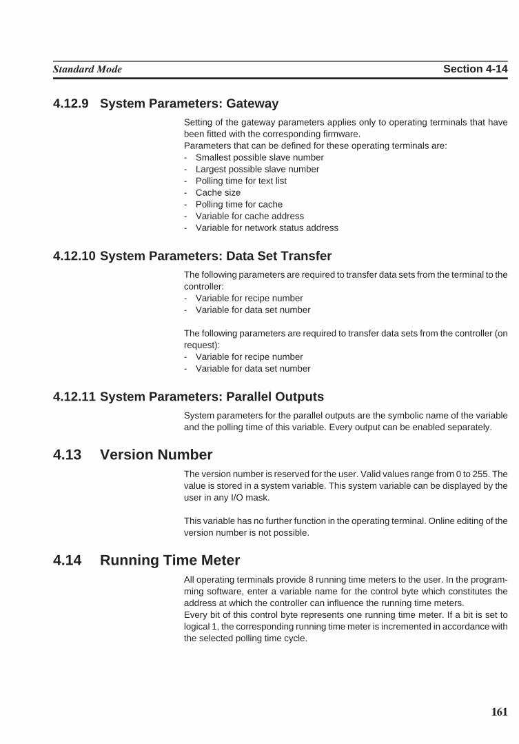
161
Standard Mode Section 4-14
4.12.9 System Parameters: GatewaySetting of the gateway parameters applies only to operating terminals that havebeen fitted with the corresponding firmware.Parameters that can be defined for these operating terminals are:- Smallest possible slave number- Largest possible slave number- Polling time for text list- Cache size- Polling time for cache- Variable for cache address- Variable for network status address
4.12.10 System Parameters: Data Set TransferThe following parameters are required to transfer data sets from the terminal to thecontroller:- Variable for recipe number- Variable for data set number
The following parameters are required to transfer data sets from the controller (onrequest):- Variable for recipe number- Variable for data set number
4.12.11 System Parameters: Parallel OutputsSystem parameters for the parallel outputs are the symbolic name of the variableand the polling time of this variable. Every output can be enabled separately.
4.13 Version NumberThe version number is reserved for the user. Valid values range from 0 to 255. Thevalue is stored in a system variable. This system variable can be displayed by theuser in any I/O mask.
This variable has no further function in the operating terminal. Online editing of theversion number is not possible.
4.14 Running Time MeterAll operating terminals provide 8 running time meters to the user. In the program-ming software, enter a variable name for the control byte which constitutes theaddress at which the controller can influence the running time meters.Every bit of this control byte represents one running time meter. If a bit is set tological 1, the corresponding running time meter is incremented in accordance withthe selected polling time cycle.
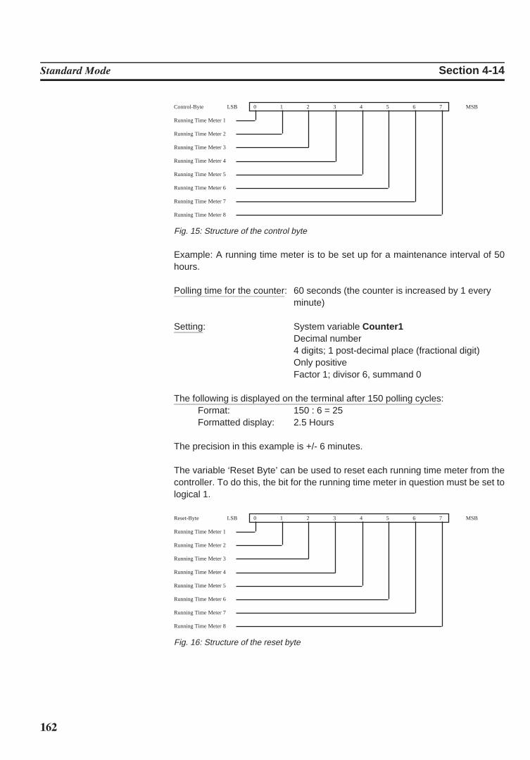
162
Standard Mode Section 4-14
Control-Byte LSB 0 1 2 3 4 5 6 7 MSB
Running Time Meter 1
Running Time Meter 2
Running Time Meter 3
Running Time Meter 4
Running Time Meter 5
Running Time Meter 6
Running Time Meter 7
Running Time Meter 8
Fig. 15: Structure of the control byte
Example: A running time meter is to be set up for a maintenance interval of 50hours.
Polling time for the counter: 60 seconds (the counter is increased by 1 everyminute)
Setting: System variable Counter1Decimal number4 digits; 1 post-decimal place (fractional digit)Only positiveFactor 1; divisor 6, summand 0
The following is displayed on the terminal after 150 polling cycles:Format: 150 : 6 = 25Formatted display: 2.5 Hours
The precision in this example is +/- 6 minutes.
The variable ‘Reset Byte’ can be used to reset each running time meter from thecontroller. To do this, the bit for the running time meter in question must be set tological 1.
Reset-Byte LSB 0 1 2 3 4 5 6 7 MSB
Running Time Meter 1
Running Time Meter 2
Running Time Meter 3
Running Time Meter 4
Running Time Meter 5
Running Time Meter 6
Running Time Meter 7
Running Time Meter 8
Fig. 16: Structure of the reset byte
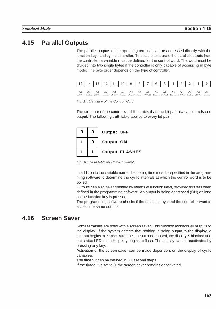
163
Standard Mode Section 4-16
4.15 Parallel OutputsThe parallel outputs of the operating terminal can be addressed directly with thefunction keys and by the controller. To be able to operate the parallel outputs fromthe controller, a variable must be defined for the control word. The word must bedivided into two single bytes if the controller is only capable of accessing in bytemode. The byte order depends on the type of controller.
15 14 13 12 11 10 9 8 7 6 5 4 3 2 1 0
A1 A1 A2 A2 A3 A3 A4 A4 A5 A5 A6 A6 A7 A7 A8 A8ON/OFF Flashes ON/OFF Flashes ON/OFF Flashes ON/OFF Flashes ON/OFF Flashes ON/OFF Flashes ON/OFF Flashes ON/OFF Flashes
Fig. 17: Structure of the Control Word
The structure of the control word illustrates that one bit pair always controls oneoutput. The following truth table applies to every bit pair:
00000 00000 Output OFF
11111 00000 Output ON
11111 11111 Output FLASHES
Fig. 18: Truth table for Parallel Outputs
In addition to the variable name, the polling time must be specified in the program-ming software to determine the cyclic intervals at which the control word is to bepolled.Outputs can also be addressed by means of function keys, provided this has beendefined in the programming software. An output is being addressed (ON) as longas the function key is pressed.The programming software checks if the function keys and the controller want toaccess the same outputs.
4.16 Screen SaverSome terminals are fitted with a screen saver. This function monitors all outputs tothe display. If the system detects that nothing is being output to the display, atimeout begins to elapse. After the timeout has elapsed, the display is blanked andthe status LED in the Help key begins to flash. The display can be reactivated bypressing any key. Activation of the screen saver can be made dependent on the display of cyclicvariables.The timeout can be defined in 0.1 second steps.If the timeout is set to 0, the screen saver remains deactivated.
164
Standard Mode Section 4-19
4.17 Image of the Mask NumberThe mask number is a mask-specific code which the terminal writes to the controll-er variable entered here. The terminal writes the mask number of the currently displayed mask into this var-iable whenever a new mask is activated. The variable is assigned in the variablelist. In this list, a word address of the controller must be assigned to the symbolicname. The respective mask number can then be read from this address and beprocessed further as required. A 16-bit variable must be reserved for the masknumber. Also see the evaluation of the function keys and soft keys, etc.
4.18 Image of the Mode Selector SwitchIn standard mode, the image of the mode selector switch (user mode switch) istransmitted to the controller after the initialization phase is complete. The user hasthe option of evaluating any unassigned DIP-switches in the controller. This allowsthe user to call up specific programs in the controller or to create queries in a serviceroutine.
4.19 Terminal ClockEvery operating terminal is fitted with a real-time clock. The parameters of thisreal-time clock can be set in the system parameters.Once per poll cycle, the real-time clock stores the current time, date and day of theweek to the defined variable in the connected controller.The connected controller itself can also transfer its current time, date and day of theweek to the terminal.This allows the time and clock in the controller, if any, to be synchronized or pro-vides the real-time if controllers are not fitted with a clock.Formats and contents of the variables must be identical with those in chapter ‘Im-age of Date and Time’. To cause the terminal to read this variable, the controllerneeds to transfer the control code 7FF9H through the serial message channel.
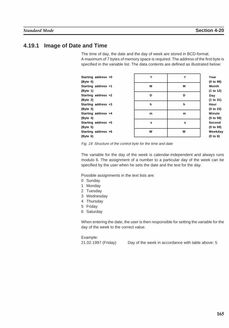
165
Standard Mode Section 4-20
4.19.1 Image of Date and Time The time of day, the date and the day of week are stored in BCD-format.A maximum of 7 bytes of memory space is required. The address of the first byte isspecified in the variable list. The data contents are defined as illustrated below:
Starting address +0 Y Y Year(Byte 0) (0 to 99)Starting address +1 M M Month
Day
(Byte 1) (1 to 12)Starting address +2 D D(Byte 2) (1 to 31)Starting address +3 h h Hour(Byte 3) (0 to 23)Starting address +4 m m Minute(Byte 4) (0 to 59)Starting address +5 s s Second(Byte 5) (0 to 59)Starting address +6 W W Weekday(Byte 6) (0 to 6)
Fig. 19: Structure of the control byte for the time and date
The variable for the day of the week is calendar-independent and always runsmodulo 6. The assignment of a number to a particular day of the week can bespecified by the user when he sets the date and the text for the day.
Possible assignments in the text lists are:0 Sunday1 Monday2 Tuesday3 Wednesday4 Thursday5 Friday6 Saturday
When entering the date, the user is then responsible for setting the variable for theday of the week to the correct value.
Example:21.02.1997 (Friday) Day of the week in accordance with table above: 5
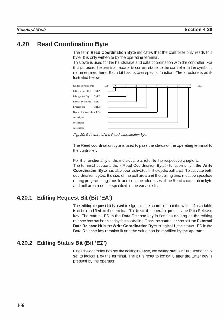
166
Standard Mode Section 4-20
4.20 Read Coordination ByteThe term Read Coordination Byte indicates that the controller only reads thisbyte. It is only written to by the operating terminal. This byte is used for the handshake and data coordination with the controller. Forthis purpose, the terminal reports its current status to the controller in the symbolicname entered here. Each bit has its own specific function. The structure is as il-lustrated below:
Read coordination byte LSB 0 1 2 3 4 5 6 7 MSB
Editing request flag Bit EA
Editing status flag Bit EZ
Refresh request flag Bit RA
Liveness flag Bit LM
Data set download aktive DDA
not assigned
not assigned
not assigned
Fig. 20: Structure of the Read coordination byte
The Read coordination byte is used to pass the status of the operating terminal tothe controller.
For the functionality of the individual bits refer to the respective chapters.The terminal supports the ,Read Coordination Byte. function only if the WriteCoordination Byte has also been activated in the cyclic poll area. To activate bothcoordination bytes, the size of the poll area and the polling time must be specifiedduring programming time. In addition, the addresses of the Read coordination byteand poll area must be specified in the variable list.
4.20.1 Editing Request Bit (Bit ‘EA’)The editing request bit is used to signal to the controller that the value of a variableis to be modified on the terminal. To do so, the operator presses the Data Releasekey. The status LED in the Data Release key is flashing as long as the editingrelease has not been set by the controller. Once the controller has set the ExternalData Release bit in the Write Coordination Byte to logical 1, the status LED in theData Release key remains lit and the value can be modified by the operator.
4.20.2 Editing Status Bit (Bit ‘EZ’)Once the controller has set the editing release, the editing status bit is automaticallyset to logical 1 by the terminal. The bit is reset to logical 0 after the Enter key ispressed by the operator.
167
Standard Mode Section 4-20
4.20.3 Refresh Request Bit (Bit ‘RA’)The refresh request function is set up by using an input variable with the PLC-Handshake attribute. With this function, a data release for the next input variable inthe same mask will not be set until a refresh acknowledgement has been receivedfrom the controller.Upon request, the controller can then refresh the next variable (bit ‘RA’ = 1) beforesending a refresh acknowledgement (bit ‘RQ’ in the Write coordination byte = 1),thereby ensuring that the value the operator works with is current.
4.20.4 Liveness Flag (Bit ‘LM’)With some communication protocols it is not possible to check, from the controllerend, whether or not the interface is in operating condition. This is why the livenessflag function has been introduced - a simple functionality that has proven to be veryeffective in practice.Whenever the PLC wants to know whether a connection is still established, it writesa logical 1, and later a logical 0, to bit 3 of the Write Coordination Byte . The operating terminal constantly monitors the liveness flag in the Write Coor-dination Byte and compares it with the status of the liveness flag in the ReadCoordination Byte . As soon as a discrepancy occurs, the operating terminal copies the Liveness FlagBit from the Write Coordination Byte to the Read Coordination Byte .
The controller is now responsible for checking within a timeout whether both statesare in agreement. The transfer times and polling times must be taken into accountwhen defining the timeout.
4.20.5 Data Set Download Active (Bit ‘DDA’)The Data Set Download Active bit remains set to logical 1 for as long as a data setis being transferred. The bit is reset after all of the data have been transferred. Thecontroller can then work with the new values in the recipe.
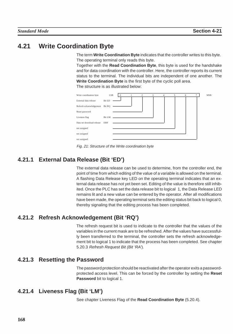
168
Standard Mode Section 4-21
4.21 Write Coordination ByteThe term Write Coordination Byte indicates that the controller writes to this byte. The operating terminal only reads this byte. Together with the Read Coordination Byte , this byte is used for the handshakeand for data coordination with the controller. Here, the controller reports its currentstatus to the terminal. The individual bits are independent of one another. TheWrite Coordination Byte is the first byte of the cyclic poll area.The structure is as illustrated below:
Write coordination byte LSB 0 1 2 3 4 5 6 7 MSB
External data release Bit ED
Refresh acknowledgement Bit RQ
Reset password
Liveness flag Bit LM
Data set download release DDF
not assigned
not assigned
not assigned
Fig. 21: Structure of the Write coordination byte
4.21.1 External Data Release (Bit ‘ED’)The external data release can be used to determine, from the controller end, thepoint of time from which editing of the value of a variable is allowed on the terminal.A flashing Data Release key LED on the operating terminal indicates that an ex-ternal data release has not yet been set. Editing of the value is therefore still inhib-ited. Once the PLC has set the data release bit to logical 1, the Data Release LEDremains lit and a new value can be entered by the operator. After all modificationshave been made, the operating terminal sets the editing status bit back to logical 0,thereby signaling that the editing process has been completed.
4.21.2 Refresh Acknowledgement (Bit ‘RQ’)The refresh request bit is used to indicate to the controller that the values of thevariables in the current mask are to be refreshed. After the values have successful-ly been transferred to the terminal, the controller sets the refresh acknowledge-ment bit to logical 1 to indicate that the process has been completed. See chapter5.20.3 Refresh Request Bit (Bit ‘RA’).
4.21.3 Resetting the PasswordThe password protection should be reactivated after the operator exits a password-protected access level. This can be forced by the controller by setting the ResetPassword bit to logical 1.
4.21.4 Liveness Flag (Bit ‘LM’)See chapter Liveness Flag of the Read Coordination Byte (5.20.4).
169
Standard Mode Section 4-22
4.21.5 Data Set Download Release (Bit ‘DDF’)The Data Set Download Release (DDF) bit allows the controller to determine thepoint of time from which transfer of a data set to the controller can begin.
4.22 Cyclic Poll AreaIn addition to a random read and write access to controller variables, a 23-bytememory area is defined in the user description as the cyclic poll area.
The cyclic poll area consists of:- 1 byte Write coordination byte- 2 bytes serial message channel (low and high byte)- a terminal-specific number of control bytes for the status LEDs in the function
keysThe poll area is written to by the controller and polled by the operating terminal atcyclic intervals. During this process, the controller can trigger, control, enable orinhibit actions that are connected with the terminal. In addition, the liveness flag ofthe Write coordination byte can be used to verify whether or not the connection withthe terminal is still established. Actions are triggered and serial messages arepassed to the operating terminal via the serial message channel (for example,transfer of data sets, change of masks). The bits of the control bytes can be used toactivate or deactivate the status LEDs in the function keys or to place them to theflashing mode.
The marginal conditions regarding the memory area for the poll area are:- the PLC accesses the Write coordination byte and status LEDs in bit mode and
the serial message channel in byte mode or word mode- the terminal accesses in byte or word mode- the memory area must be contiguous.
The symbolic name for the cyclic poll area is specified in the parameters for the pollarea using the programming system. The assignment of the starting address of thisarea is defined in the variable list.Note that access to byte and word structures is not identical. Once an access meth-od is selected, it should be applied throughout.
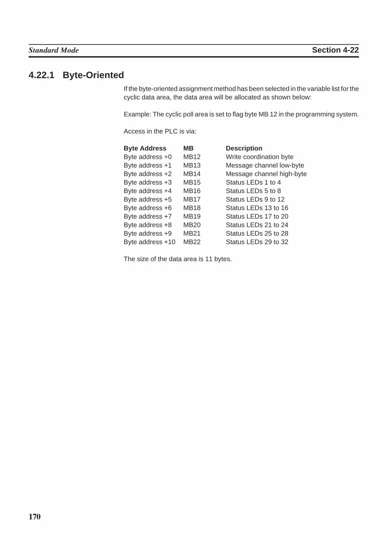
170
Standard Mode Section 4-22
4.22.1 Byte-OrientedIf the byte-oriented assignment method has been selected in the variable list for thecyclic data area, the data area will be allocated as shown below:
Example: The cyclic poll area is set to flag byte MB 12 in the programming system.
Access in the PLC is via:
Byte Address MB DescriptionByte address +0 MB12 Write coordination byteByte address +1 MB13 Message channel low-byteByte address +2 MB14 Message channel high-byteByte address +3 MB15 Status LEDs 1 to 4Byte address +4 MB16 Status LEDs 5 to 8Byte address +5 MB17 Status LEDs 9 to 12Byte address +6 MB18 Status LEDs 13 to 16Byte address +7 MB19 Status LEDs 17 to 20Byte address +8 MB20 Status LEDs 21 to 24Byte address +9 MB21 Status LEDs 25 to 28Byte address +10 MB22 Status LEDs 29 to 32
The size of the data area is 11 bytes.

171
Standard Mode Section 4-22
The structure of the byte-oriented cyclic poll area is as shown below:
Bit 7 Bit 6 Bit 5 Bit 4 Bit 3 Bit 2 Bit 1 Bit 0
Byte address +0 not used not used not used DDF LM PL RQ ED
Byte address +1 serial message channel low-byte
Byte address +2 serial message channel high-byte
Byte address +3 LED1 LED1 LED2 LED2 LED3 LED3 LED4 LED4
on/off flashing on/off flashing on/off flashing on/off flashing
Byte address +4 LED5 LED5 LED6 LED6 LED7 LED7 LED8 LED8
on/off flashing on/off flashing on/off flashing on/off flashing
Byte address +5 LED9 LED9 LED10 LED10 LED11 LED11 LED12 LED12
on/off flashing on/off flashing on/off flashing on/off flashing
Byte address +6 LED13 LED13 LED14 LED14 LED15 LED15 LED16 LED16
on/off flashing on/off flashing on/off flashing on/off flashing
Byte address +7 LED17 LED17 LED18 LED18 LED19 LED19 LED20 LED20
on/off flashing on/off flashing on/off flashing on/off flashing
Byte address +8 LED21 LED21 LED22 LED22 LED23 LED23 LED24 LED24
on/off flashing on/off flashing on/off flashing on/off flashing
Byte address +9 LED25 LED25 LED26 LED26 LED27 LED27 LED28 LED28
on/off flashing on/off flashing on/off flashing on/off flashing
Byte address +10 LED29 LED29 LED30 LED30 LED31 LED31 LED32 LED32
on/off flashing on/off flashing on/off flashing on/off flashing
Byte address +11 LED33 LED33 LED34 LED34 LED35 LED35 LED36 LED36
on/off flashing on/off flashing on/off flashing on/off flashing
Byte address +12 LED37 LED37 LED38 LED38 LED39 LED39 LED40 LED40
on/off flashing on/off flashing on/off flashing on/off flashing
Byte address +13 LED41 LED41 LED42 LED42 LED43 LED43 LED44 LED44
on/off flashing on/off flashing on/off flashing on/off flashing
Byte address +14 LED45 LED45 LED46 LED46 LED47 LED47 LED48 LED48
on/off flashing on/off flashing on/off flashing on/off flashing
Fig. 22: Byte-oriented poll area
4.22.2 Word-OrientedThe structure of the word-oriented cyclic poll area is as shown below:
Bit 15 Bit 14 Bit 13 Bit 12 Bit 11 Bit 10 Bit 9 Bit 8 Bit 7 Bit 6 Bit 5 Bit 4 Bit 3 Bit 2 Bit 1 Bit 0
Word address + 0 not used not used not used DDF LM PL RQ ED not used not used not used not used not used not used not used not used
Word address + 1 serial message channel low byte serial message channgel high byte
Word address + 2 LED1 LED1 LED2 LED2 LED3 LED3 LED4 LED4 LED5 LED5 LED6 LED6 LED7 LED7 LED8 LED8
on/off flashing on/off flashing on/off flashing on/off flashing on/off flashing on/off flashing on/off flashing on/off flashing
Word address + 3 LED9 LED9 LED10 LED10 LED11 LED11 LED12 LED12 LED13 LED13 LED14 LED14 LED15 LED15 LED16 LED16
on/off flashing on/off flashing on/off flashing on/off flashing on/off flashing on/off flashing on/off flashing on/off flashing
Word address + 4 LED17 LED17 LED18 LED18 LED19 LED19 LED20 LED20 LED21 LED21 LED22 LED22 LED23 LED23 LED24 LED24
on/off flashing on/off flashing on/off flashing on/off flashing on/off flashing on/off flashing on/off flashing on/off flashing
Word address + 5 LED25 LED25 LED26 LED26 LED27 LED27 LED28 LED28 LED29 LED29 LED30 LED30 LED31 LED31 LED32 LED32
on/off flashing on/off flashing on/off flashing on/off flashing on/off flashing on/off flashing on/off flashing on/off flashing
Word address + 6 LED33 LED33 LED34 LED34 LED35 LED35 LED36 LED36 LED37 LED37 LED38 LED38 LED39 LED39 LED40 LED40
on/off flashing on/off flashing on/off flashing on/off flashing on/off flashing on/off flashing on/off flashing on/off flashing
Word address + 7 LED41 LED41 LED42 LED42 LED43 LED43 LED44 LED44 LED45 LED45 LED46 LED46 LED47 LED47 LED48 LED48
on/off flashing on/off flashing on/off flashing on/off flashing on/off flashing on/off flashing on/off flashing on/off flashing
Fig. 23: Word-oriented poll area
172
Standard Mode Section 4-22
Example: The cyclic poll area is set to DW 21 in the programming system:
Word Address DW High Byte Low ByteWord address +0 DW21 Write coordination byte ReservedWord address +1 DW22 Message channel high-byte Message channel low-
byteWord address +2 DW23 Status LEDs 1 to 4 Status LEDS 5 to 8Word address +3 DW24 Status LEDs 9 to 12 Status LEDS 13 to 16Word address +4 DW25 Status LEDs 17 to 20 Status LEDS 21 to 24Word address +5 DW26 Status LEDs 25 to 28 Status LEDS 29 to 32
4.22.3 Image of the LEDsThe image of the LEDs enables the PLC to control the status LEDs in the functionkeys. Functions that can be set for each status LED are the functions ON, OFF andFLASHING. Whenever the controller sets a bit, the associated LED on the oper-ating terminal is influenced accordingly.It is important here that the size of the poll area and the polling time were setappropriately. Not defining these additional parameters may cause problems whenthe LED is addressed.
In the case of a function key that is to directly select a message mask, the statusLED is influenced by the message system. The message system uses this statusLED to indicate that a new message has been received but not yet acknowledged.To be able to influence the status LED in this function key from the controller, themessage priority must be set to 0 (zero). See chapter 4.11.5 Status LEDs in theFunction Keys.
00000 00000 Status LED OFF
11111 00000 Status LED ON
11111 11111 Status LED FLASHES
Fig. 24: Truth table for status LEDs
4.22.4 Serial Message Channel The serial message channel is a part of the cyclic poll area and is used to transfer16-bit information. The numbers of serial messages, selection of message masks,external selection of masks and transfer of control codes are made possible via thisdata channel.
The following handshake is used for the information transfer: the PLC stores avalue (. 0) in this data word. This value is then transferred to the operating termi-nal which will write the value 0 into this data word again. This indicates to the PLCthat it can now transfer the next value. The value is interpreted by the operatingterminal and its function is executed.
173
Standard Mode Section 4-23
Values can be:- Message numbers- Mask numbers (mask number + 8000H)- Control codes
4.22.5 Polling TimeThe polling time is the frequency with which the variables for the cyclic poll area areto be read by the operating terminal. This setting is specified in the system para-meters for the poll area. Polling of this variable includes the Write CoordinationByte , the Serial Message Channel and the Image of the status LED . With mostprotocols, settings of around half a second have worked well. If the setting for thecycle time is too short, the interface protocol can no longer meet the requirementsresulting in poorer reaction times. There is no general recommendation since theoptions depend on the user description involved. Time settings should, however,be at least greater than 100 ms.
4.22.6 Size of the Poll AreaThe maximum size is 23 bytes depending on the data type and type of terminal. Thepoll area size can be adapted to the area that is actually used if the image of theLED or part of this function is not to be used. The default size for all operatingterminals is 12 bytes.
4.23 Control CodesControl codes have already been mentioned in the previous sections which can beused to trigger certain actions or functions in the operating terminal. All of theseactions are initiated by the controller by writing the desired control code to the serialmessage channel within the poll area.An explanation of these control codes is provided below.
4.23.1 Triggering Data Set PrintoutsThe following hex code can be used from the controller to cause the current data setto be output to the printer connected to the operating terminal.
Hexadecimal code: 7FF8H
The operating terminal can indicate the status of the print process by writing eitherof two values to the address for the recipe number variable.
0 Data set printout ok.255 Data set with the desired data set number can not be printed.
4.23.2 Setting the Clock in the Operating TerminalThe following hex code can be used from the controller to cause the real-time clockin the operating terminal to be set in accordance with the specifications in the de-fined control word.
Hexadecimal code: 7FF9H
174
Standard Mode Section 4-23
4.23.3 Transferring Data Sets from the Controller to the TerminalThe following hex code can be used from the controller to initiate the transfer of adata set from the controller to the operating terminal. This requires that the recipenumber and data set number are specified by the controller first.The data sets are transferred as a block.
The following variables must be defined:- Recipe number for the Request from Controller (System Parameters: Data Set
Transfer)- Data set number for the Request from Controller (System Parameters: Data Set
Transfer)
Hexadecimal code: 7FFAH
4.23.4 Transferring Data Sets from the Terminal to the ControllerThe following hex code can be used from the controller to initiate the transfer of adata set from the operating terminal to the controller. This requires that the recipenumber and data set number are specified by the controller first.
The following variables must be defined:- Recipe number for the Request from Controller (System Parameters: Data Set
Transfer)- Data set number for the Request from Controller (System Parameters: Data Set
Transfer)
Hexadecimal code: 7FFBH
4.23.5 Transferring Data Sets from the Controller to the Terminal(Individually)
The following hex code can be used from the controller to initiate the transfer of adata set from the controller to the operating terminal. This requires that the recipenumber and data set number are specified by the controller first.The data sets are transferred individually.
The following variables must be defined:- Recipe number for the Transfer from the terminal (System Parameters: Data
Set Transfer)- Data set number for the Transfer from the terminal (System Parameters: Data
Set Transfer)
Hexadecimal code: 7FFDH
175
Standard Mode Section 4-26
4.23.6 Refreshing the Message SystemThe following hex code can be used from the controller to cause the operatingterminal to read in the most recent parallel messages.This procedure can be used to achieve an event-controlled message system.
Hexadecimal code: 7FFFH
4.24 Cyclic VariablesThe term Cyclic Variables refers to data which may change continuously while amask is displayed, i.e. all types of ACTUAL VALUES. The terminal must thereforepoll the controller for the current values at cyclic intervals. The time selected herespecifies the intervals at which these mask values are refreshed. In addition to the cyclic variables, the terminal also polls the controller for the cur-rent status of the Write coordination byte, the serial message channel and theLEDs (update). This process is either time or event controlled depending on theprotocol. No polling will take place if the value = 0 is entered for the time period. Ifthis variable is not polled, then an external control of the data release is not pos-sible, for example.
4.25 Interface ParametersThe interface parameters selected in the programming system are stored in themask memory. It is, however, possible to modify the data in the operating terminalat a later date. Values modified in the operating terminal are retained in the battery-backed RAM. When necessary, the original settings can be restored at any time.The parameters of the interface channel SER1 are determined by the protocol.Modifications to any of these parameters could result in communication failures.Values that are not typical are detected when the terminal is initialized and a mess-age to this effect is generated.The parameters of the interface channel SER2 are reserved for control of a printerand, when transferring data. This process requires that the settings for both de-vices must match. The selected parameters do not apply to the download. For thedownload, the system will automatically switch to the highest possible transmissionrate.
4.26 Variable DefinitionThe variable definition contained in the user description defines the format, type,range of values, scaling and attribute of the representation. All controller-independ-ent parameters are stored here. For editable variables, it is additionally possible toinfluence the Editor and the transfer mode to the controller. The variable definitioncontains the symbolic name of the variables, the format definition and, if necessary,the text lists in the case of selection text variables.
176
Standard Mode Section 4-26
4.26.1 Variable ListThe variable list contains the assignment of symbolic variable names to the desti-nation hardware. Due to its design and proximity to the PLC, this file is alwaysmanufacturer-specific.In the programming software, the variable list is a part of the database.The variable list contains only the required manufacturer-specific user descriptionparts. Its size is therefore small in relation to the entire project. A project can bequickly adapted to other PLC specifications by simply adapting the variable list tothe PLC to be used.
A variable list can be created in the programming system in two ways.First method:As a variable is defined in a mask (with or without address information) it is enteredinto the variable list at the same time.
Second Method:The first step can be to define the entries in the variable list or alternatively to insertthem from any suitable program via the clipboard. The entries will immediately beavailable in the programming software on a global basis.
Third Method:The elements of the variable list are imported from a Siemens SEQ file or a BoschSXS file. Only the relevant data of the import files will be extracted and inserted intothe variable list.
4.27 Application ProgrammingThe operating concept is based on a mask structure that can be created by the userin accordance with the requirements and on system variables that can influenceimportant functions in the operating terminal. Various types of masks are availableto facilitate the creation of solutions for standard tasks.Every mask structure initially consists of 4 types of masks whose contents areuser-configurable.
Any I/O mask can be programmed as a system mask.- Setup mask- Start mask- Password mask- Main mask
After being switched on, the operating terminal is initialized and displays the startupmask during this process. The setup mask can be called up by pressing the Enterkey while the startup mask is displayed. The setup mask can be exited by pressingthe Enter key again and the startup mask will reappear. The next mask of the operating guidance that is displayed is the Main Mask whichrepresents the first mask of the user-programmed operator guidance. A menu withmenu items is normally set up in the main mask to allow selection of lower-levelmasks. The user has the option of specifying a full-page help text for every maskwhich can be displayed by the operator with the Help key.
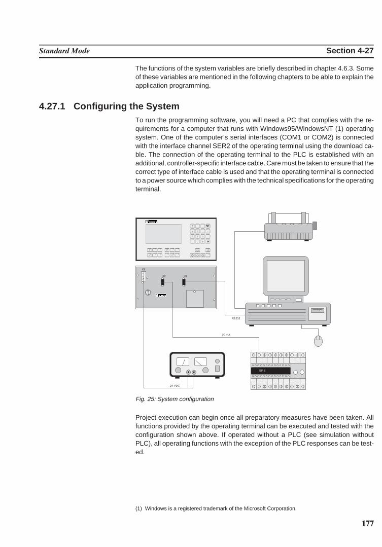
177
Standard Mode Section 4-27
The functions of the system variables are briefly described in chapter 4.6.3. Someof these variables are mentioned in the following chapters to be able to explain theapplication programming.
4.27.1 Configuring the SystemTo run the programming software, you will need a PC that complies with the re-quirements for a computer that runs with Windows95/WindowsNT (1) operatingsystem. One of the computer’s serial interfaces (COM1 or COM2) is connectedwith the interface channel SER2 of the operating terminal using the download ca-ble. The connection of the operating terminal to the PLC is established with anadditional, controller-specific interface cable. Care must be taken to ensure that thecorrect type of interface cable is used and that the operating terminal is connectedto a power source which complies with the technical specifications for the operatingterminal.
RS 232
20 mA
S P S
X3
X1
X2
24 VDC
Fig. 25: System configuration
Project execution can begin once all preparatory measures have been taken. Allfunctions provided by the operating terminal can be executed and tested with theconfiguration shown above. If operated without a PLC (see simulation withoutPLC), all operating functions with the exception of the PLC responses can be test-ed.
(1) Windows is a registered trademark of the Microsoft Corporation.
178
Standard Mode Section 4-27
4.27.2 Programming SystemsThe programming system provides all of the capabilities required to convenientlyand quickly program the entire range of functions offered by an operating terminal.The programming system requires either Windows95 or Windows NT 4.0. It offersWindows-conforming operability in conjunction with all of the means provided byWindows (OLE, COPY/CUT/PASTE, WYSIWYG). The programming softwareprovides a help system that can be reached with the Help key or the function key F1from anywhere within the program (online help).
The programming system operates similarly to a database. All project-related dataare collected in this database and are organized into a project.
This project can then be compiled into a S3 file and transferred to the terminal usingthe download function.
4.27.3 Project DescriptionThe project description consists of:
at least the user description (one per language)a variable list (controller-specific)the global data (parameters)and, if used, parts of the graphical library.
The user description contains all of the controller-independent information. Sym-bolic names are inserted for all controller-specific variables. The assignment of these symbolic names to the hardware is specified in the vari-able list. This makes it possible to easily change to another controller manufacturerwithout having to recreate the masks, variable definition or operating functionality.The adaptation to a different controller type can be accomplished by simply replac-ing the variable list.
4.27.3.1 Multilingual Projects
The mask contents of a user description determines the language in which the textsare displayed. To make an operator interface available in multiple languages, theuser description of each language is stored with a language number. The desiredlanguage can then be selected online via a system variable using the assignedlanguage number. The number of languages that can be stored is limited only by the size of the maskmemory. Please note that it is not necessary that the length of the texts, the vari-ables and the number of masks are identical in the various languages.
The number of the currently active language is stored in the operating terminal andis retained when the terminal is switched off. When booted again, the terminaldefaults to the language which was active when the terminal was turned off. In thecase of a loss of data, the language that corresponds to the number 0 is automat-ically displayed.
179
Standard Mode Section 4-27
The language can easily be selected on the operating terminal using a selectiontext. The language can then be selected with the Cursor up and Cursor down keys.
Overview of the required steps:1. Create a text list with the language name (Example: Deutsch, English, Fran-
çaise)2. Create the mask3. Create the variable in the mask:
OSLanguage , representation method, selection text, text list name as createdin step 1.
Attention: Do not enter system variables in the variable list. This would result in thecontroller addresses being accessed instead of the internal operating terminal ad-dresses.
4.27.3.2 Variants of a Project
The system variable OsLanguage also permits the management of variants. Forexample, if you design a machine with various options but do not want the operatorof the machine to be distracted by these options, it is possible to select the appropri-ate variant online on the terminal.
Example:VALUE FUNCTION0 Variant 11 Variant 22 Variant 3
The variants may differ in operating structure, the number of masks as well as thevariables used. The advantage is that the user description must be maintained onlyonce for the entire system.Example:A possible application is when a system is to be operated with the metric and Anglo-Saxon dimensions. In this case, the format and scaling of the variable inputs andoutputs could be switched from millimeter to inches along with the language.
4.27.4 Project DocumentationThe programming software also allows the generation of extensive documentationon the project. Detailed information on how to use variables, the scaling para-meters, representation methods, mask contents as well as the operator guidancefacilitate verification of the user description.The documentation should cover any information necessary to recreate the userdescription in the event of a loss of data.
4.27.4.1 Creating Documentation
The programming system offers extensive dialogs that allow those elements to beselected that are to be documented.The documentation can then be easily processed further using word processingprograms or desktop publishing programs.
180
Standard Mode Section 4-27
4.27.5 Project Back-upA project is backed up by storing the source files onto various data mediums, asrecommended by the PC manufacturers. For information on the available optionsrefer to your PC’s operator system manual.
In addition, we recommend that the projects are printed using the documentationfunctions.
4.27.6 Optimizing the Transmission RateThe operating concept supports free access to various data types and datalengths. Although, the extent to which the various protocols actually support this free accessvaries greatly. The firmware of the terminal optimizes the access method mask-specifically to achieve extremely short access times. This method means that an attempt is made to transmit several variables to thedisplay simultaneously. The user can actively contribute to this process by keepingthe number of different variable types used in one mask to a minimum and byaddressing variables of one type contiguously (small gaps are no problem!). Thisallows shorter refresh intervals and reduces the load on the interface.
4.28 Downloading the User DescriptionThe download function describes how a new project is loaded into the terminal’sFlash memory. Before a new project can be downloaded, the terminal must beplaced into the download mode. The download mode is activated by:- Writing a ‘1’ to the system variable IntEraseEPROM in an I/O mask.- Switching off the supply voltage, setting the user-mode switch S4 to ON, turning the device back on and once the following message is displayed
switching the user-mode switch S4 to OFF again with the power on.
While programming, you may want to activate the automatic download function.This will automatically switch the operating terminal into the download mode when-ever a download is started on the PC.
When the download function is activated, the user description currently stored inthe terminal will be erased and the following information will appear on the displayat the cursor position (1.1):
A new user description can now be transferred to the terminal using the ProjectManagement dialog in the programming system. For this process, the PC must beconnected to interface channel SER2 of the terminal using the download cable.To prevent the user description from accidentally being erased during operation, itis possible to assign an appropriately high access level to the mask with the down.
181
Standard Mode Section 4-28
load function, so a password is required to access the mask. If the mask has beenassigned to a control key, the operator will not even know that such a mask exists.Another method would be to prevent input by using the connected controller. Thepassword protection function is not required in this case. With this method, thecontroller will provide data release for the mask number with the download functiononly, if specific conditions set out by the user are fulfilled.
If the user does not want to make use of these options, another alternative to thesoftware solution via the system variable IntEraseEPROM would be to erase theold variable definition with the aid of the user-mode switch S4. This will requirestrict adherence to the routine to be executed. Subsequently the terminal will auto-matically activate the download operating mode.To place the operating terminal to the download operating mode:The Flash memory is erased once the system variable has been activated. Thefollowing message is displayed during this process:
After the Flash memory has been erased, this is indicated by the following mes-sage:
The terminal now automatically activates the download mode and the followingmessage appears:
The terminal is now ready to receive a new user description via interface channelSER2 and to store it in the Flash memory. The progress of the data transfer will beindicated on the display by the characters ‘.....’, the number of characters willtherefore change continuously!After the transfer is complete, the following message is displayed:
After the transfer, the terminal immediately starts the initialization phase and dis-plays the startup mask of the user description.Various error messages may appear on the display during the download or at thebeginning of the initialization phase:
ADDRESS ERROR Error in the address calculations of the com-piler
FLASH MEMORY FAILURE The loaded user description contains errors oris incomplete.
CHECKSUM ERROR The user description contains errors, please re-compile.
BYTECOUNT OVERFLOW The user description contains errors, please re-compile.
FORMAT ERROR (S0, S3, S7) Sequences in the S3 file that was transferredcontains errors.
182
Standard Mode Section 4-28
The display of an error message indicates that the transferred user description isincomplete or contains errors. Switching the terminal off and on at this point willautomatically reactivate the download operating mode.
4.28.1 Downloading with WindowsThe programming software does not necessarily have to be used for downloading.Another option is to use the program Terminal that is available under MS Windows(group ‘Accessories’).The following steps are required:1. Connect COM1 or COM2 of the PC with the interface channel SER2 using the
download cable2. Double-click the Terminal icon under Windows3. Set the parameters:Menu:Settings:
Communication: 19200Bd7 bitsodd parityxon/xoff1 stop bit
Transfers:Send text file: (Enter file name) xxxxx.S3
4.28.2 Application MemoryThe terminals come fitted with a 256 kByte Flash memory. Flash memory is non-volatile either as UV-EPROMs are, but flash memory can be erased and writtenwithout putting it out of the appliance. Therefore the application can easily andquickly be tested or setup to new conditions.
4.28.3 Loading an ApplicationTo load the application, a PC must be connected to interface channel SER2 usingthe download cable. The terminal must then be placed to the download mode. Thefollowing message must appear on the display:
The terminal is now ready to receive a new application via interface channel SER2and store it in the Flash memory.Now the download of an error-free user description ‘name S.3’ must be activatedusing the Project Management dialog in the programming software.The progress of the data transfer will be indicated on the display by the characters‘.....’, the number of characters will therefore change continuously.The download transmission can either be controlled by a beam in the dialog boxAfter the transmission is complete, the following is displayed
to indicate that the transfer has completed. After the transfer, the terminal immediate-ly starts the initialization phase and displays the start mask of the user description.
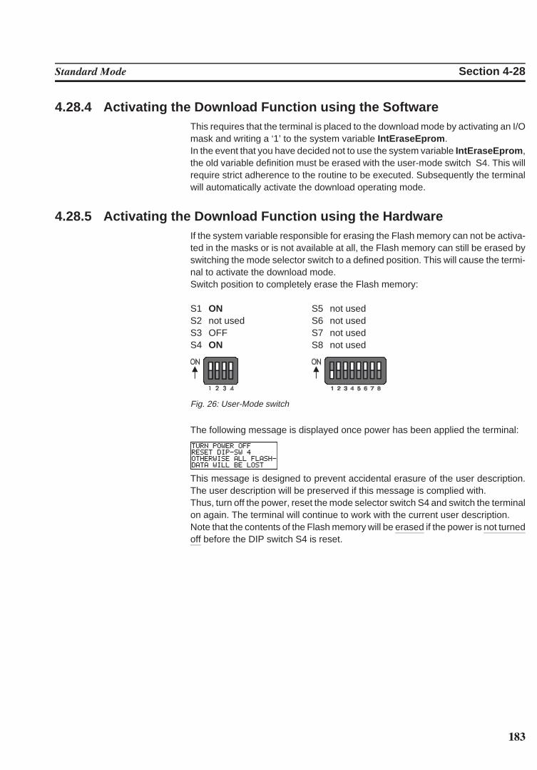
183
Standard Mode Section 4-28
4.28.4 Activating the Download Function using the SoftwareThis requires that the terminal is placed to the download mode by activating an I/Omask and writing a ‘1’ to the system variable IntEraseEprom . In the event that you have decided not to use the system variable IntEraseEprom ,the old variable definition must be erased with the user-mode switch S4. This willrequire strict adherence to the routine to be executed. Subsequently the terminalwill automatically activate the download operating mode.
4.28.5 Activating the Download Function using the HardwareIf the system variable responsible for erasing the Flash memory can not be activa-ted in the masks or is not available at all, the Flash memory can still be erased byswitching the mode selector switch to a defined position. This will cause the termi-nal to activate the download mode.Switch position to completely erase the Flash memory:
S1 ON S5 not usedS2 not used S6 not usedS3 OFF S7 not usedS4 ON S8 not used
Fig. 26: User-Mode switch
The following message is displayed once power has been applied the terminal:
This message is designed to prevent accidental erasure of the user description.The user description will be preserved if this message is complied with. Thus, turn off the power, reset the mode selector switch S4 and switch the terminalon again. The terminal will continue to work with the current user description.Note that the contents of the Flash memory will be erased if the power is not turnedoff before the DIP switch S4 is reset.
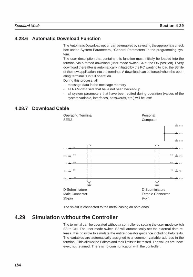
184
Standard Mode Section 4-29
4.28.6 Automatic Download FunctionThe Automatic Download option can be enabled by selecting the appropriate checkbox under ‘System Parameters’, ‘General Parameters’ in the programming sys-tem.The user description that contains this function must initially be loaded into theterminal via a forced download (user-mode switch S4 at the ON position). Everydownload thereafter is automatically initiated by the PC wanting to load the S3 fileof the new application into the terminal. A download can be forced when the oper-ating terminal is in full operation.During this process, all- message data in the message memory- all RAM-data sets that have not been backed-up- all system parameters that have been edited during operation (values of the
system variable, interfaces, passwords, etc.) will be lost!
4.28.7 Download CableOperating Terminal PersonalSER2 Computer
2 W HT D
2W HR D
5G YG N D
7 G YG N D
4 G NR T S
3 B NR D
5 YEC T S
8G NC T S
3B NT D
7YER T S
1D C D
4D T R
6D S R
D-Subminiature D-SubminiatureMale Connector Female Connector25-pin 9-pin
The shield is connected to the metal casing on both ends.
4.29 Simulation without the ControllerThe terminal can be operated without a controller by setting the user-mode switchS3 to ON. The user-mode switch S3 will automatically set the external data re-lease. It is possible to simulate the entire operator guidance including help texts.The variables are automatically assigned to a common variable address in theterminal. This allows the Editors and their limits to be tested. The values are, how-ever, not retained. There is no communication with the controller.
185
SECTION 5Transparent Mode
This section describes the transparent mode in detail. In transparant mode the PT reacts as an ANSI terminal.
5.1 Setting the Operating Mode . . . . . . . . . . . . . . . . . . . . . . . . . . . . . . . . . . . . . . . . . . . . . . . . . . . . . . . . . . . . . . . . . 1875.2 Start-up Processes . . . . . . . . . . . . . . . . . . . . . . . . . . . . . . . . . . . . . . . . . . . . . . . . . . . . . . . . . . . . . . . . . . . . . . . . . . . 1875.3 Communication in the Transparent Mode . . . . . . . . . . . . . . . . . . . . . . . . . . . . . . . . . . . . . . . . . . . . . . . . . . . . 188
5.3.1 Interface Parameters . . . . . . . . . . . . . . . . . . . . . . . . . . . . . . . . . . . . . . . . . . . . . . . . . . . . . . . . . . . . . . . . . 1885.3.2 Receive Buffer for SER1 . . . . . . . . . . . . . . . . . . . . . . . . . . . . . . . . . . . . . . . . . . . . . . . . . . . . . . . . . . . . . 188
5.4 Function Setup Menu . . . . . . . . . . . . . . . . . . . . . . . . . . . . . . . . . . . . . . . . . . . . . . . . . . . . . . . . . . . . . . . . . . . . . . . 1895.4.1 Adaptation of the Parameters in the Setup Menu. . . . . . . . . . . . . . . . . . . . . . . . . . . . . . . . . . . . . . 1895.4.2 Example of a Properly Performed Modification!. . . . . . . . . . . . . . . . . . . . . . . . . . . . . . . . . . . . . . . 1895.4.3 Setup Menu NT4S-SF121B-E, NT4S-SF122B-E, NT4S-SF123B-E . . . . . . . . . . . . . . . . . . . . . . 190
5.5 Display . . . . . . . . . . . . . . . . . . . . . . . . . . . . . . . . . . . . . . . . . . . . . . . . . . . . . . . . . . . . . . . . . . . . . . . . . . . . . . . . . . . . . 1915.5.1 Character Set, Character Attributes . . . . . . . . . . . . . . . . . . . . . . . . . . . . . . . . . . . . . . . . . . . . . . . . . . 191
5.6 Keys . . . . . . . . . . . . . . . . . . . . . . . . . . . . . . . . . . . . . . . . . . . . . . . . . . . . . . . . . . . . . . . . . . . . . . . . . . . . . . . . . . . . . . . . 1925.6.1 Key Codes for the Operating Terminals. . . . . . . . . . . . . . . . . . . . . . . . . . . . . . . . . . . . . . . . . . . . . . . 192
5.7 Interface Control Characters. . . . . . . . . . . . . . . . . . . . . . . . . . . . . . . . . . . . . . . . . . . . . . . . . . . . . . . . . . . . . . . . . 1935.7.1 LED Codes for the Operating Terminals. . . . . . . . . . . . . . . . . . . . . . . . . . . . . . . . . . . . . . . . . . . . . . 1945.7.2 Control Sequences for the Operating Terminals . . . . . . . . . . . . . . . . . . . . . . . . . . . . . . . . . . . . . . . 194
5.8 Error Messages . . . . . . . . . . . . . . . . . . . . . . . . . . . . . . . . . . . . . . . . . . . . . . . . . . . . . . . . . . . . . . . . . . . . . . . . . . . . . 197

186
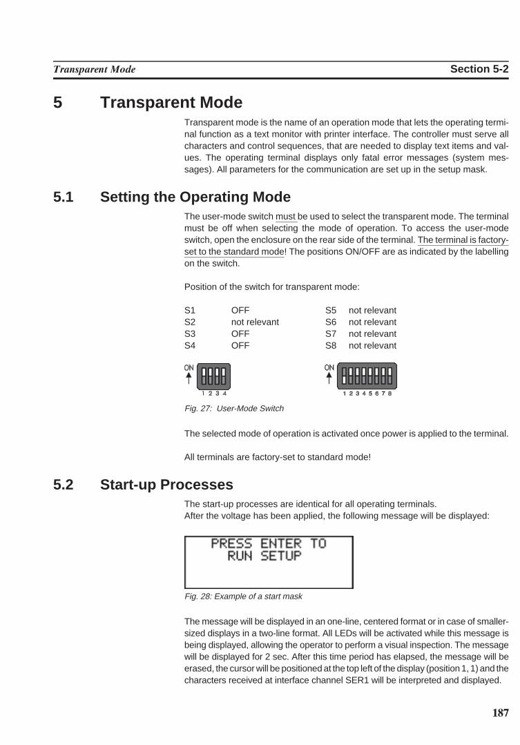
187
Transparent Mode Section 5-2
5 Transparent ModeTransparent mode is the name of an operation mode that lets the operating termi-nal function as a text monitor with printer interface. The controller must serve allcharacters and control sequences, that are needed to display text items and val-ues. The operating terminal displays only fatal error messages (system mes-sages). All parameters for the communication are set up in the setup mask.
5.1 Setting the Operating ModeThe user-mode switch must be used to select the transparent mode. The terminalmust be off when selecting the mode of operation. To access the user-modeswitch, open the enclosure on the rear side of the terminal. The terminal is factory-set to the standard mode! The positions ON/OFF are as indicated by the labellingon the switch.
Position of the switch for transparent mode:
S1 OFF S5 not relevantS2 not relevant S6 not relevantS3 OFF S7 not relevantS4 OFF S8 not relevant
Fig. 27: User-Mode Switch
The selected mode of operation is activated once power is applied to the terminal.
All terminals are factory-set to standard mode!
5.2 Start-up ProcessesThe start-up processes are identical for all operating terminals.After the voltage has been applied, the following message will be displayed:
Fig. 28: Example of a start mask
The message will be displayed in an one-line, centered format or in case of smaller-sized displays in a two-line format. All LEDs will be activated while this message isbeing displayed, allowing the operator to perform a visual inspection. The messagewill be displayed for 2 sec. After this time period has elapsed, the message will beerased, the cursor will be positioned at the top left of the display (position 1, 1) and thecharacters received at interface channel SER1 will be interpreted and displayed.
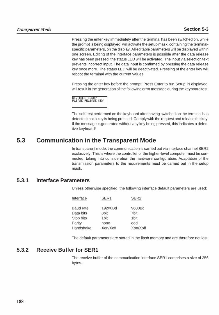
188
Transparent Mode Section 5-3
Pressing the enter key immediately after the terminal has been switched on, whilethe prompt is being displayed, will activate the setup mask, containing the terminal-specific parameters, on the display. All editable parameters will be displayed withinone screen. Editing of the interface parameters is possible after the data releasekey has been pressed, the status LED will be activated. The input via selection textprevents incorrect input. The data input is confirmed by pressing the data releasekey once more. The status LED will be deactivated. Pressing of the enter key willreboot the terminal with the current values.
Pressing the enter key before the prompt ‘Press Enter to run Setup’ is displayed,will result in the generation of the following error message during the keyboard test.
The self-test performed on the keyboard after having switched on the terminal hasdetected that a key is being pressed. Comply with the request and release the key.If the message is generated without any key being pressed, this indicates a defec-tive keyboard!
5.3 Communication in the Transparent ModeIn transparent mode, the communication is carried out via interface channel SER2exclusively. This is where the controller or the higher-level computer must be con-nected, taking into consideration the hardware configuration. Adaptation of thetransmission parameters to the requirements must be carried out in the setupmask.
5.3.1 Interface ParametersUnless otherwise specified, the following interface default parameters are used:
Interface SER1 SER2
Baud rate 19200Bd 9600BdData bits 8bit 7bitStop bits 1bit 1bitParity none oddHandshake Xon/Xoff Xon/Xoff
The default parameters are stored in the flash memory and are therefore not lost.
5.3.2 Receive Buffer for SER1The receive buffer of the communication interface SER1 comprises a size of 256bytes.
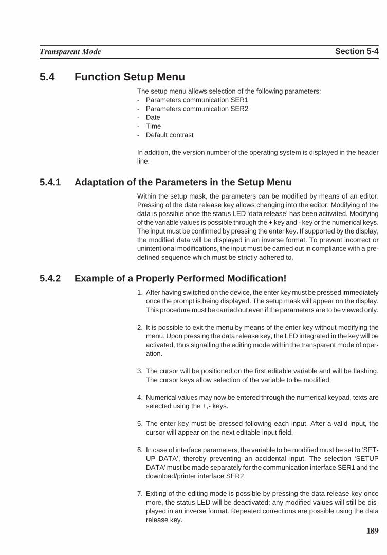
189
Transparent Mode Section 5-4
5.4 Function Setup MenuThe setup menu allows selection of the following parameters:- Parameters communication SER1- Parameters communication SER2- Date- Time- Default contrast
In addition, the version number of the operating system is displayed in the headerline.
5.4.1 Adaptation of the Parameters in the Setup MenuWithin the setup mask, the parameters can be modified by means of an editor.Pressing of the data release key allows changing into the editor. Modifying of thedata is possible once the status LED ‘data release’ has been activated. Modifyingof the variable values is possible through the + key and - key or the numerical keys.The input must be confirmed by pressing the enter key. If supported by the display,the modified data will be displayed in an inverse format. To prevent incorrect orunintentional modifications, the input must be carried out in compliance with a pre-defined sequence which must be strictly adhered to.
5.4.2 Example of a Properly Performed Modification!1. After having switched on the device, the enter key must be pressed immediately
once the prompt is being displayed. The setup mask will appear on the display.This procedure must be carried out even if the parameters are to be viewed only.
2. It is possible to exit the menu by means of the enter key without modifying themenu. Upon pressing the data release key, the LED integrated in the key will beactivated, thus signalling the editing mode within the transparent mode of oper-ation.
3. The cursor will be positioned on the first editable variable and will be flashing.The cursor keys allow selection of the variable to be modified.
4. Numerical values may now be entered through the numerical keypad, texts areselected using the +,- keys.
5. The enter key must be pressed following each input. After a valid input, thecursor will appear on the next editable input field.
6. In case of interface parameters, the variable to be modified must be set to ‘SET-UP DATA’, thereby preventing an accidental input. The selection ‘SETUPDATA’ must be made separately for the communication interface SER1 and thedownload/printer interface SER2.
7. Exiting of the editing mode is possible by pressing the data release key oncemore, the status LED will be deactivated; any modified values will still be dis-played in an inverse format. Repeated corrections are possible using the datarelease key.
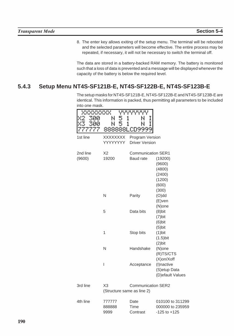
190
Transparent Mode Section 5-4
8. The enter key allows exiting of the setup menu. The terminal will be rebootedand the selected parameters will become effective. The entire process may berepeated, if necessary, it will not be necessary to switch the terminal off.
The data are stored in a battery-backed RAM memory. The battery is monitoredsuch that a loss of data is prevented and a message will be displayed whenever thecapacity of the battery is below the required level.
5.4.3 Setup Menu NT4S-SF121B-E, NT4S-SF122B-E, NT4S-SF123B-EThe setup masks for NT4S-SF121B-E, NT4S-SF122B-E and NT4S-SF123B-E areidentical. This information is packed, thus permitting all parameters to be includedinto one mask.
1st line XXXXXXXX Program VersionYYYYYYYY Driver Version
2nd line X2 Communication SER119200 Baud rate (19200)
(9600)(9600)
(4800)(2400)(1200)(600)(300)
N Parity (O)dd(E)ven(N)one
5 Data bits (8)bit(7)bit(6)bit(5)bit
1 Stop bits (1)bit(1.5)bit(2)bit
N Handshake (N)one(R)TS/CTS(X)on/Xoff
I Acceptance (I)nactive(S)etup Data(D)efault Values
3rd line X3 Communication SER2(Structure same as line 2)
4th line 777777 Date 010100 to 311299888888 Time 000000 to 2359599999 Contrast -125 to +125
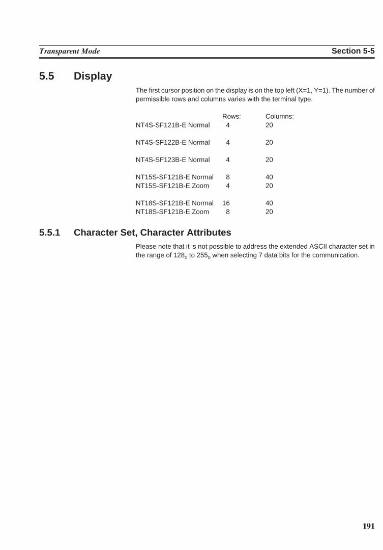
191
Transparent Mode Section 5-5
5.5 DisplayThe first cursor position on the display is on the top left (X=1, Y=1). The number ofpermissible rows and columns varies with the terminal type.
Rows: Columns:NT4S-SF121B-E Normal 4 20
NT4S-SF122B-E Normal 4 20
NT4S-SF123B-E Normal 4 20
NT15S-SF121B-E Normal 8 40NT15S-SF121B-E Zoom 4 20
NT18S-SF121B-E Normal 16 40NT18S-SF121B-E Zoom 8 20
5.5.1 Character Set, Character AttributesPlease note that it is not possible to address the extended ASCII character set inthe range of 128D to 255D when selecting 7 data bits for the communication.
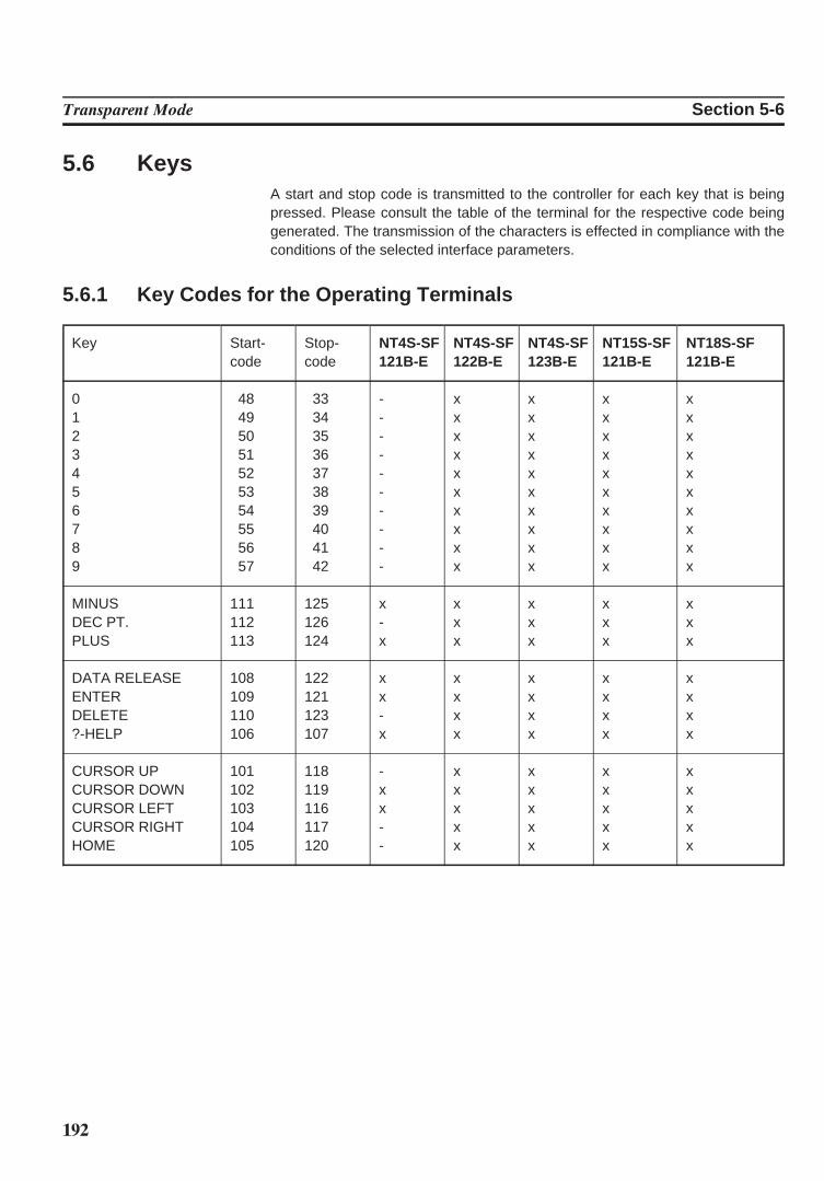
192
Transparent Mode Section 5-6
5.6 KeysA start and stop code is transmitted to the controller for each key that is beingpressed. Please consult the table of the terminal for the respective code beinggenerated. The transmission of the characters is effected in compliance with theconditions of the selected interface parameters.
5.6.1 Key Codes for the Operating Terminals
Key Start- Stop- NT4S-SF NT4S-SF NT4S-SF NT15S-SF NT18S-SFcode code 121B-E 122B-E 123B-E 121B-E 121B-E
0 48 33 - x x x x1 49 34 - x x x x2 50 35 - x x x x3 51 36 - x x x x4 52 37 - x x x x5 53 38 - x x x x6 54 39 - x x x x7 55 40 - x x x x8 56 41 - x x x x9 57 42 - x x x x
MINUS 111 125 x x x x xDEC PT. 112 126 - x x x xPLUS 113 124 x x x x x
DATA RELEASE 108 122 x x x x xENTER 109 121 x x x x xDELETE 110 123 - x x x x?-HELP 106 107 x x x x x
CURSOR UP 101 118 - x x x xCURSOR DOWN 102 119 x x x x xCURSOR LEFT 103 116 x x x x xCURSOR RIGHT 104 117 - x x x xHOME 105 120 - x x x x
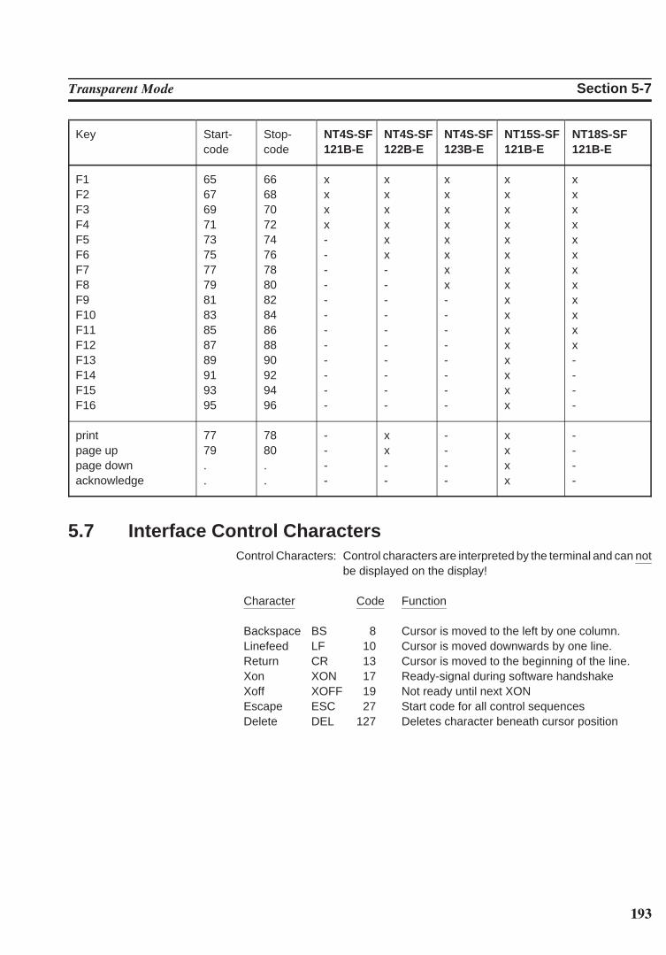
193
Transparent Mode Section 5-7
Key Start- Stop- NT4S-SF NT4S-SF NT4S-SF NT15S-SF NT18S-SFcode code 121B-E 122B-E 123B-E 121B-E 121B-E
F1 65 66 x x x x xF2 67 68 x x x x xF3 69 70 x x x x xF4 71 72 x x x x xF5 73 74 - x x x xF6 75 76 - x x x xF7 77 78 - - x x xF8 79 80 - - x x xF9 81 82 - - - x xF10 83 84 - - - x xF11 85 86 - - - x xF12 87 88 - - - x xF13 89 90 - - - x -F14 91 92 - - - x -F15 93 94 - - - x -F16 95 96 - - - x -
print 77 78 - x - x -page up 79 80 - x - x -page down . . - - - x -acknowledge . . - - - x -
5.7 Interface Control CharactersControl Characters: Control characters are interpreted by the terminal and can not
be displayed on the display!
Character Code Function
Backspace BS 8 Cursor is moved to the left by one column.Linefeed LF 10 Cursor is moved downwards by one line.Return CR 13 Cursor is moved to the beginning of the line.Xon XON 17 Ready-signal during software handshakeXoff XOFF 19 Not ready until next XONEscape ESC 27 Start code for all control sequencesDelete DEL 127 Deletes character beneath cursor position
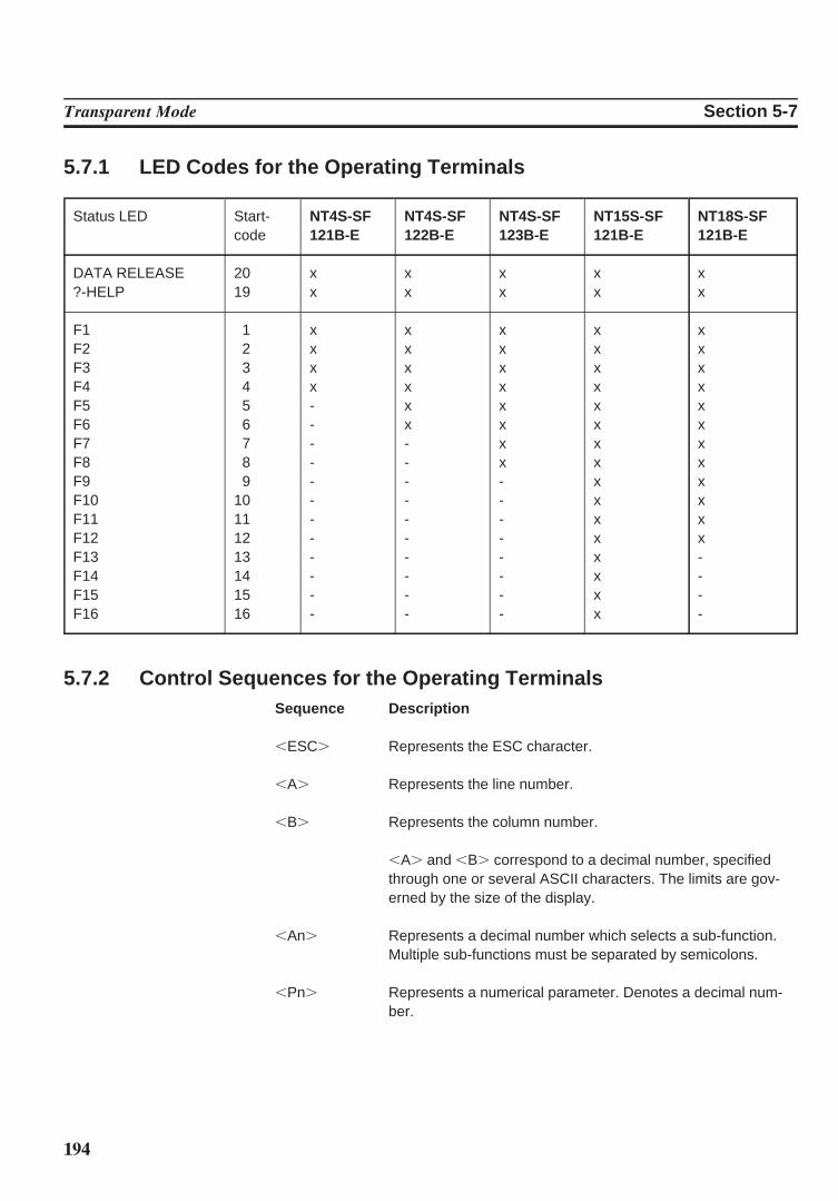
194
Transparent Mode Section 5-7
5.7.1 LED Codes for the Operating Terminals
Status LED Start- NT4S-SF NT4S-SF NT4S-SF NT15S-SF NT18S-SFcode 121B-E 122B-E 123B-E 121B-E 121B-E
DATA RELEASE 20 x x x x x?-HELP 19 x x x x x
F1 1 x x x x xF2 2 x x x x xF3 3 x x x x xF4 4 x x x x xF5 5 - x x x xF6 6 - x x x xF7 7 - - x x xF8 8 - - x x xF9 9 - - - x xF10 10 - - - x xF11 11 - - - x xF12 12 - - - x xF13 13 - - - x -F14 14 - - - x -F15 15 - - - x -F16 16 - - - x -
5.7.2 Control Sequences for the Operating TerminalsSequence Description
,ESC. Represents the ESC character.
,A. Represents the line number.
,B. Represents the column number.
,A. and ,B. correspond to a decimal number, specifiedthrough one or several ASCII characters. The limits are gov-erned by the size of the display.
,An. Represents a decimal number which selects a sub-function.Multiple sub-functions must be separated by semicolons.
,Pn. Represents a numerical parameter. Denotes a decimal num-ber.
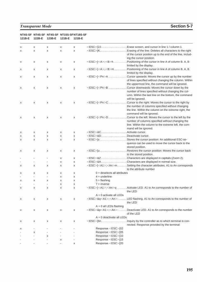
195
Transparent Mode Section 5-7
NT4S-SF NT4S-SF NT4S-SF NT15S-SFNT18S-SF121B-E 122B-E 123B-E 121B-E 121B-E
x x x x x ,ESC.[2J. . . . . . . . . . . . . . . . . . . . .Erase screen, and cursor in line 1 / column 1.x x x x x ,ESC.[K. . . . . . . . . . . . . . . . . . . . . .Erasing of the line: Deletes all characters to the right
of the cursor position up to the end of the line, includ-ing the cursor position.
x x x x x ,ESC.[,A.;,B.h . . . . . . . . . . .Positioning of the cursor in line A of column B. A, Blimited by the display.
x x x x x ,ESC.[,A.;,B.H. . . . . . . . . . .Positioning of the cursor in line A of column B. A, Blimited by the display.
x x x x x ,ESC.[,Pn.A . . . . . . . . . . . . . . .Cursor upwards: Moves the cursor up by the numberof lines specified without changing the column. Withinthe uppermost line, the command will be ignored.
x x x x x ,ESC.[,Pn.B . . . . . . . . . . . . . . .Cursor downwards: Moves the cursor down by thenumber of lines specified without changing the col-umn. Within the last line on the bottom, the commandwill be ignored.
x x x x x ,ESC.[,Pn.C . . . . . . . . . . . . . . .Cursor to the right: Moves the cursor to the right bythe number of columns specified without changingthe line. Within the column on the extreme right, thecommand will be ignored.
x x x x x ,ESC.[,Pn.D . . . . . . . . . . . . . . .Cursor to the left: Moves the cursor to the left by thenumber of columns specified without changing theline. Within the column to the extreme left, the com-mand will be ignored.
x x x x x ,ESC.&C. . . . . . . . . . . . . . . . . . . . .Activate cursor.x x x x x ,ESC.&D. . . . . . . . . . . . . . . . . . . . .Deactivate cursor.x x x x x ,ESC.[s . . . . . . . . . . . . . . . . . . . . . .Stores the cursor position: An additional ESC-se-
quence can be used to move the cursor back to thestored position.
x x x x x ,ESC.[u . . . . . . . . . . . . . . . . . . . . . .Restores the cursor position: Moves the cursor backto the stored position.
- - - x x ,ESC.&Z . . . . . . . . . . . . . . . . . . . . .Characters are displayed in capitals (Zoom 2).- - - x x ,ESC.&A. . . . . . . . . . . . . . . . . . . . .Characters are displayed in normal size.x x x x x ,ESC.[,A1.;,An.m. . . . . . . .Setting the character attributes. A1 to An corresponds
to the attribute numberx x x x x 0 = deselects all attributes- - - x x 4 = underlinex x x x x 5 = flashing- - - x x 7 = inversex x x x x ,ESC.[,A1.;,An.q . . . . . . . .Activate LED. A1 to An corresponds to the number of
the LEDA = 0 activate all LEDs
x x x x x ,ESC.&q,A1.;,An.: . . . . . . .LED flashing. A1 to An corresponds to the number ofthe LED
A = 0 all LEDs flashingx x x x x ,ESC.&p,A1.;,An.: . . . . . . .Deactivate LED. A1 to An corresponds to the number
of the LEDA = 0 deactivate all LEDs
x x x x x ,ESC.[6n. . . . . . . . . . . . . . . . . . . . .Inquiry by the controller as to which terminal is con-nected. Response provided by the terminal:
x - - - - Response ,ESC.[02- x - - - Response ,ESC.[05- - x - - Response ,ESC.[10- - - x - Response ,ESC.[15- - - - x Response ,ESC.[20
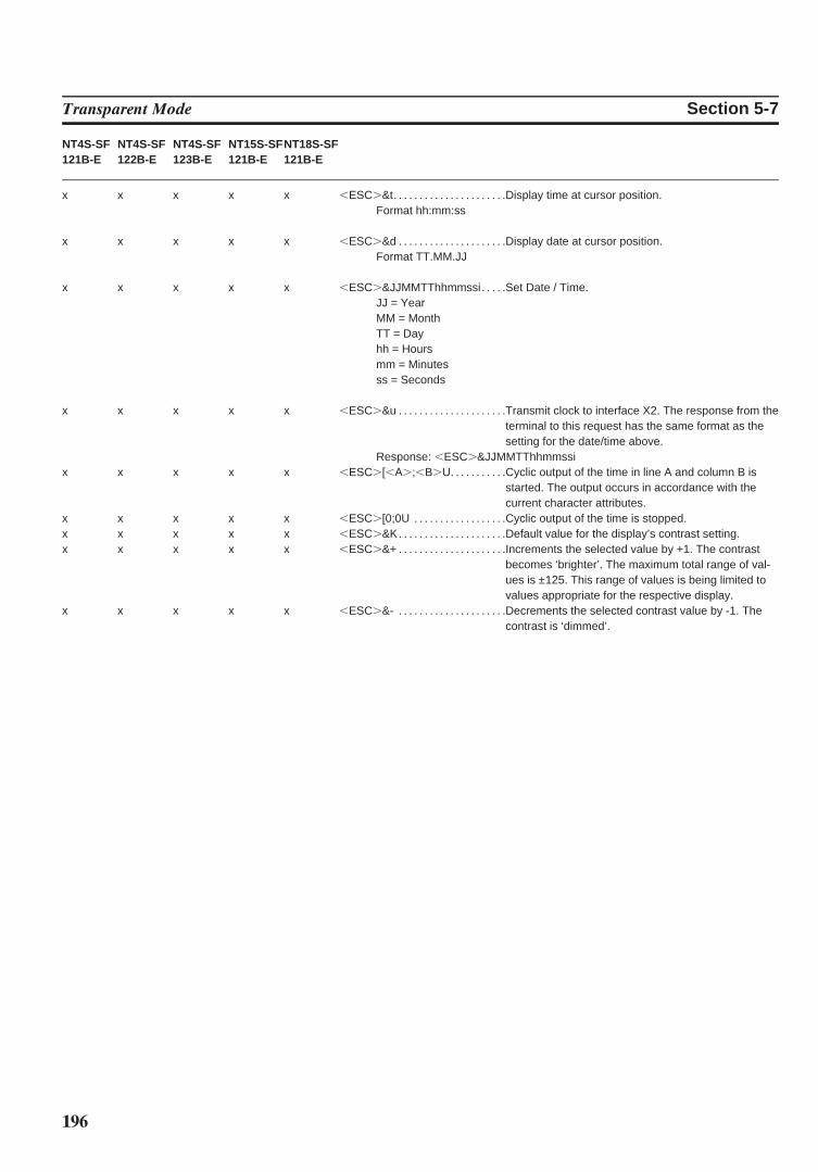
196
Transparent Mode Section 5-7
NT4S-SF NT4S-SF NT4S-SF NT15S-SFNT18S-SF121B-E 122B-E 123B-E 121B-E 121B-E
x x x x x ,ESC.&t. . . . . . . . . . . . . . . . . . . . . .Display time at cursor position.Format hh:mm:ss
x x x x x ,ESC.&d . . . . . . . . . . . . . . . . . . . . .Display date at cursor position.Format TT.MM.JJ
x x x x x ,ESC.&JJMMTThhmmssi. . . . .Set Date / Time.JJ = YearMM = MonthTT = Dayhh = Hoursmm = Minutesss = Seconds
x x x x x ,ESC.&u . . . . . . . . . . . . . . . . . . . . .Transmit clock to interface X2. The response from theterminal to this request has the same format as thesetting for the date/time above.
Response: ,ESC.&JJMMTThhmmssix x x x x ,ESC.[,A.;,B.U. . . . . . . . . . .Cyclic output of the time in line A and column B is
started. The output occurs in accordance with thecurrent character attributes.
x x x x x ,ESC.[0;0U . . . . . . . . . . . . . . . . . .Cyclic output of the time is stopped.x x x x x ,ESC.&K. . . . . . . . . . . . . . . . . . . . .Default value for the display’s contrast setting.x x x x x ,ESC.&+ . . . . . . . . . . . . . . . . . . . . .Increments the selected value by +1. The contrast
becomes ‘brighter’. The maximum total range of val-ues is ±125. This range of values is being limited tovalues appropriate for the respective display.
x x x x x ,ESC.&- . . . . . . . . . . . . . . . . . . . . .Decrements the selected contrast value by -1. Thecontrast is ‘dimmed’.
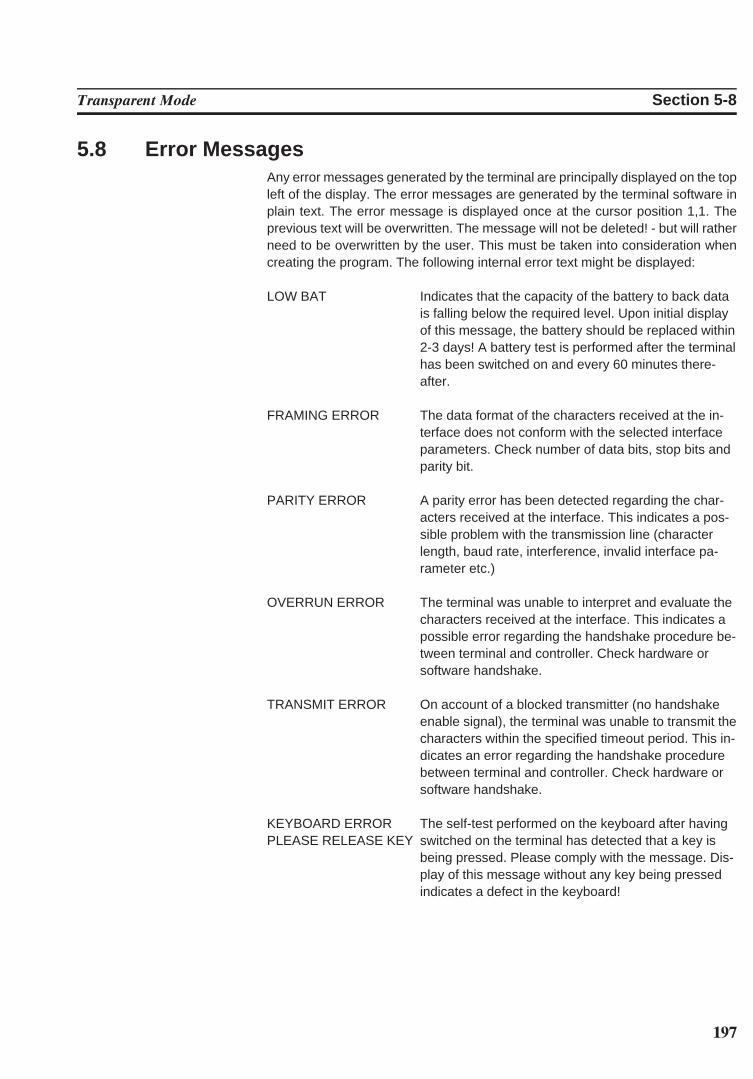
197
Transparent Mode Section 5-8
5.8 Error MessagesAny error messages generated by the terminal are principally displayed on the topleft of the display. The error messages are generated by the terminal software inplain text. The error message is displayed once at the cursor position 1,1. Theprevious text will be overwritten. The message will not be deleted! - but will ratherneed to be overwritten by the user. This must be taken into consideration whencreating the program. The following internal error text might be displayed:
LOW BAT Indicates that the capacity of the battery to back datais falling below the required level. Upon initial displayof this message, the battery should be replaced within2-3 days! A battery test is performed after the terminalhas been switched on and every 60 minutes there-after.
FRAMING ERROR The data format of the characters received at the in-terface does not conform with the selected interfaceparameters. Check number of data bits, stop bits andparity bit.
PARITY ERROR A parity error has been detected regarding the char-acters received at the interface. This indicates a pos-sible problem with the transmission line (characterlength, baud rate, interference, invalid interface pa-rameter etc.)
OVERRUN ERROR The terminal was unable to interpret and evaluate thecharacters received at the interface. This indicates apossible error regarding the handshake procedure be-tween terminal and controller. Check hardware orsoftware handshake.
TRANSMIT ERROR On account of a blocked transmitter (no handshakeenable signal), the terminal was unable to transmit thecharacters within the specified timeout period. This in-dicates an error regarding the handshake procedurebetween terminal and controller. Check hardware orsoftware handshake.
KEYBOARD ERRORPLEASE RELEASE KEY
The self-test performed on the keyboard after havingswitched on the terminal has detected that a key isbeing pressed. Please comply with the message. Dis-play of this message without any key being pressedindicates a defect in the keyboard!

198
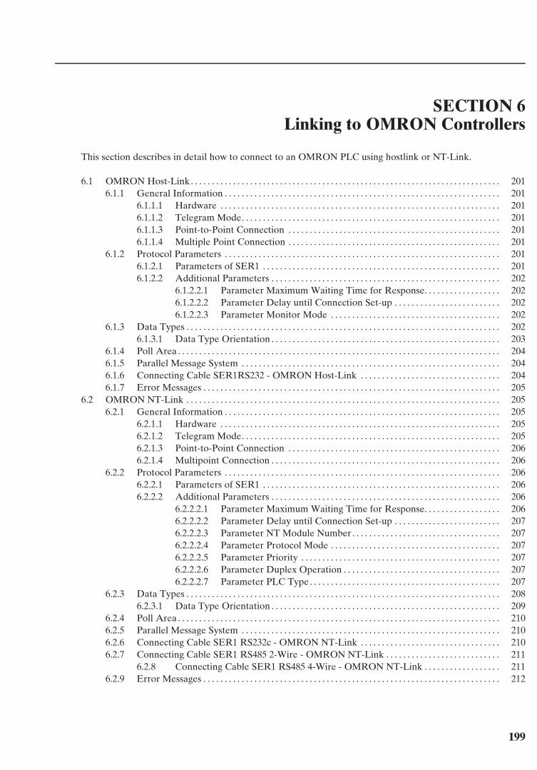
199
SECTION 6Linking to OMRON Controllers
This section describes in detail how to connect to an OMRON PLC using hostlink or NT-Link.
6.1 OMRON Host-Link. . . . . . . . . . . . . . . . . . . . . . . . . . . . . . . . . . . . . . . . . . . . . . . . . . . . . . . . . . . . . . . . . . . . . . . . . 2016.1.1 General Information . . . . . . . . . . . . . . . . . . . . . . . . . . . . . . . . . . . . . . . . . . . . . . . . . . . . . . . . . . . . . . . . . 201
6.1.1.1 Hardware . . . . . . . . . . . . . . . . . . . . . . . . . . . . . . . . . . . . . . . . . . . . . . . . . . . . . . . . . . . . . . . . . . 2016.1.1.2 Telegram Mode. . . . . . . . . . . . . . . . . . . . . . . . . . . . . . . . . . . . . . . . . . . . . . . . . . . . . . . . . . . . . 2016.1.1.3 Point-to-Point Connection . . . . . . . . . . . . . . . . . . . . . . . . . . . . . . . . . . . . . . . . . . . . . . . . . . 2016.1.1.4 Multiple Point Connection . . . . . . . . . . . . . . . . . . . . . . . . . . . . . . . . . . . . . . . . . . . . . . . . . . 201
6.1.2 Protocol Parameters . . . . . . . . . . . . . . . . . . . . . . . . . . . . . . . . . . . . . . . . . . . . . . . . . . . . . . . . . . . . . . . . . 2016.1.2.1 Parameters of SER1 . . . . . . . . . . . . . . . . . . . . . . . . . . . . . . . . . . . . . . . . . . . . . . . . . . . . . . . . 2016.1.2.2 Additional Parameters . . . . . . . . . . . . . . . . . . . . . . . . . . . . . . . . . . . . . . . . . . . . . . . . . . . . . . 202
6.1.2.2.1 Parameter Maximum Waiting Time for Response. . . . . . . . . . . . . . . . . . 2026.1.2.2.2 Parameter Delay until Connection Set-up . . . . . . . . . . . . . . . . . . . . . . . . . 2026.1.2.2.3 Parameter Monitor Mode . . . . . . . . . . . . . . . . . . . . . . . . . . . . . . . . . . . . . . . . 202
6.1.3 Data Types . . . . . . . . . . . . . . . . . . . . . . . . . . . . . . . . . . . . . . . . . . . . . . . . . . . . . . . . . . . . . . . . . . . . . . . . . . 2026.1.3.1 Data Type Orientation . . . . . . . . . . . . . . . . . . . . . . . . . . . . . . . . . . . . . . . . . . . . . . . . . . . . . . 203
6.1.4 Poll Area . . . . . . . . . . . . . . . . . . . . . . . . . . . . . . . . . . . . . . . . . . . . . . . . . . . . . . . . . . . . . . . . . . . . . . . . . . . . 2046.1.5 Parallel Message System . . . . . . . . . . . . . . . . . . . . . . . . . . . . . . . . . . . . . . . . . . . . . . . . . . . . . . . . . . . . . 2046.1.6 Connecting Cable SER1RS232 - OMRON Host-Link . . . . . . . . . . . . . . . . . . . . . . . . . . . . . . . . . 2046.1.7 Error Messages . . . . . . . . . . . . . . . . . . . . . . . . . . . . . . . . . . . . . . . . . . . . . . . . . . . . . . . . . . . . . . . . . . . . . . 205
6.2 OMRON NT-Link . . . . . . . . . . . . . . . . . . . . . . . . . . . . . . . . . . . . . . . . . . . . . . . . . . . . . . . . . . . . . . . . . . . . . . . . . . 2056.2.1 General Information . . . . . . . . . . . . . . . . . . . . . . . . . . . . . . . . . . . . . . . . . . . . . . . . . . . . . . . . . . . . . . . . . 205
6.2.1.1 Hardware . . . . . . . . . . . . . . . . . . . . . . . . . . . . . . . . . . . . . . . . . . . . . . . . . . . . . . . . . . . . . . . . . . 2056.2.1.2 Telegram Mode. . . . . . . . . . . . . . . . . . . . . . . . . . . . . . . . . . . . . . . . . . . . . . . . . . . . . . . . . . . . . 2056.2.1.3 Point-to-Point Connection . . . . . . . . . . . . . . . . . . . . . . . . . . . . . . . . . . . . . . . . . . . . . . . . . . 2066.2.1.4 Multipoint Connection . . . . . . . . . . . . . . . . . . . . . . . . . . . . . . . . . . . . . . . . . . . . . . . . . . . . . . 206
6.2.2 Protocol Parameters . . . . . . . . . . . . . . . . . . . . . . . . . . . . . . . . . . . . . . . . . . . . . . . . . . . . . . . . . . . . . . . . . 2066.2.2.1 Parameters of SER1 . . . . . . . . . . . . . . . . . . . . . . . . . . . . . . . . . . . . . . . . . . . . . . . . . . . . . . . . 2066.2.2.2 Additional Parameters . . . . . . . . . . . . . . . . . . . . . . . . . . . . . . . . . . . . . . . . . . . . . . . . . . . . . . 206
6.2.2.2.1 Parameter Maximum Waiting Time for Response. . . . . . . . . . . . . . . . . . 2066.2.2.2.2 Parameter Delay until Connection Set-up . . . . . . . . . . . . . . . . . . . . . . . . . 2076.2.2.2.3 Parameter NT Module Number . . . . . . . . . . . . . . . . . . . . . . . . . . . . . . . . . . . 2076.2.2.2.4 Parameter Protocol Mode . . . . . . . . . . . . . . . . . . . . . . . . . . . . . . . . . . . . . . . . 2076.2.2.2.5 Parameter Priority . . . . . . . . . . . . . . . . . . . . . . . . . . . . . . . . . . . . . . . . . . . . . . . 2076.2.2.2.6 Parameter Duplex Operation . . . . . . . . . . . . . . . . . . . . . . . . . . . . . . . . . . . . . 2076.2.2.2.7 Parameter PLC Type. . . . . . . . . . . . . . . . . . . . . . . . . . . . . . . . . . . . . . . . . . . . . 207
6.2.3 Data Types . . . . . . . . . . . . . . . . . . . . . . . . . . . . . . . . . . . . . . . . . . . . . . . . . . . . . . . . . . . . . . . . . . . . . . . . . . 2086.2.3.1 Data Type Orientation . . . . . . . . . . . . . . . . . . . . . . . . . . . . . . . . . . . . . . . . . . . . . . . . . . . . . . 209
6.2.4 Poll Area . . . . . . . . . . . . . . . . . . . . . . . . . . . . . . . . . . . . . . . . . . . . . . . . . . . . . . . . . . . . . . . . . . . . . . . . . . . . 2106.2.5 Parallel Message System . . . . . . . . . . . . . . . . . . . . . . . . . . . . . . . . . . . . . . . . . . . . . . . . . . . . . . . . . . . . . 2106.2.6 Connecting Cable SER1 RS232c - OMRON NT-Link . . . . . . . . . . . . . . . . . . . . . . . . . . . . . . . . . 2106.2.7 Connecting Cable SER1 RS485 2-Wire - OMRON NT-Link . . . . . . . . . . . . . . . . . . . . . . . . . . . 211
6.2.8 Connecting Cable SER1 RS485 4-Wire - OMRON NT-Link . . . . . . . . . . . . . . . . . . 2116.2.9 Error Messages . . . . . . . . . . . . . . . . . . . . . . . . . . . . . . . . . . . . . . . . . . . . . . . . . . . . . . . . . . . . . . . . . . . . . . 212

200
201
Linking to OMRON Controllers Section 6-1
6 Linking to OMRON Controllers
6.1 OMRON Host-Link
6.1.1 General InformationTesiMod operating terminals can be conveniently connected to all controllers thatsupport the OMRON Host-Link protocol. The OMRON Host-Link protocol allowscommunication between one operating terminal and up to 32 controllers.
6.1.1.1 Hardware
The interface channel SER1 RS232 is used to connect the operating terminals to aOMRON controller.
6.1.1.2 Telegram Mode
The operating terminal always has a client functionality which means that datatransfers are always initiated by the terminal.
6.1.1.3 Point-to-Point Connection
RS232 interfaces allow only point-to-point connections.Therefore the operating terminals can be set to Single-Mode or Multiple-Mode. Theselected mode must be equal to the mode set for the controller.Most of the OMRON controllers are used with Multiple-Mode and cannot be ad-justed
6.1.1.4 Multiple Point Connection
In the telegram mode Multiple-Mode the terminal can be connected to at least 32controllers using multiple point connection.In this case the terminal must be connected via the communication module NT-AL001 with the RS422-Bus.A direct connection with the RS485 interface of SER2 of the terminals is not permis-sible due to a lack of terminator possibilities.
6.1.2 Protocol Parameters
6.1.2.1 Parameters of SER1
Parameters that can be defined for the communication interface SER1 are as fol-lows:
Baud rate: 300, 600, 1200, 2400, 4800, 9600, 19200Data bits: 7, 8Parity: even , oddStop bits: 1, 2Handshake: no handshake
Default values in the programming software are in bold print.
202
Linking to OMRON Controllers Section 6-1
6.1.2.2 Additional Parameters
6.1.2.2.1 Parameter Maximum Waiting Time for Response
This parameter specifies the maximum time the operating terminal waits for a re-sponse from the PLC.The valid range of values is 50 ms to 65535 ms.The value 500 ms is specified by the programming software by default.
6.1.2.2.2 Parameter Delay until Connection Set-up
This parameter specifies the time the operating terminal waits before starting com-munication.The valid range of values is 5 s to 255 s.The value 5 s is specified by the programming software by default.
6.1.2.2.3 Parameter Monitor Mode
The PLC can be used in the RUN or MONITOR mode of operation.Write access via the protocol is not possible in the RUN mode.To be able to edit variables from the terminal, the PLC is switched to the Monitormode whenever the operating terminal is booted.
6.1.3 Data TypesThe following data types are available for direct user access.The address ranges depend on the type of PLC.The valid address ranges are specified below.
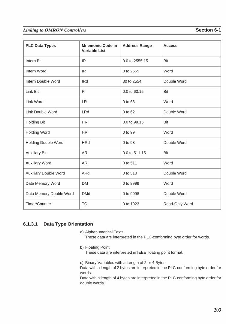
203
Linking to OMRON Controllers Section 6-1
PLC Data Types Mnemonic Code in Address Range AccessVariable List
Intern Bit IR 0.0 to 2555.15 Bit
Intern Word IR 0 to 2555 Word
Intern Double Word IRd 30 to 2554 Double Word
Link Bit R 0.0 to 63.15 Bit
Link Word LR 0 to 63 Word
Link Double Word LRd 0 to 62 Double Word
Holding Bit HR 0.0 to 99.15 Bit
Holding Word HR 0 to 99 Word
Holding Double Word HRd 0 to 98 Double Word
Auxiliary Bit AR 0.0 to 511.15 Bit
Auxiliary Word AR 0 to 511 Word
Auxiliary Double Word ARd 0 to 510 Double Word
Data Memory Word DM 0 to 9999 Word
Data Memory Double Word DMd 0 to 9998 Double Word
Timer/Counter TC 0 to 1023 Read-Only Word
6.1.3.1 Data Type Orientation
a) Alphanumerical TextsThese data are interpreted in the PLC-conforming byte order for words.
b) Floating PointThese data are interpreted in IEEE floating point format.
c) Binary Variables with a Length of 2 or 4 BytesData with a length of 2 bytes are interpreted in the PLC-conforming byte order forwords.Data with a length of 4 bytes are interpreted in the PLC-conforming byte order fordouble words.
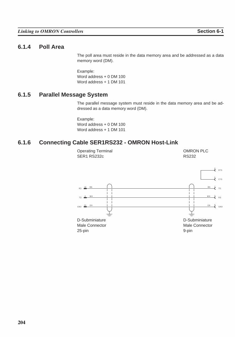
204
Linking to OMRON Controllers Section 6-1
6.1.4 Poll AreaThe poll area must reside in the data memory area and be addressed as a datamemory word (DM).
Example:Word address + 0 DM 100Word address + 1 DM 101
6.1.5 Parallel Message SystemThe parallel message system must reside in the data memory area and be ad-dressed as a data memory word (DM).
Example:Word address + 0 DM 100Word address + 1 DM 101
6.1.6 Connecting Cable SER1RS232 - OMRON Host-LinkOperating Terminal OMRON PLCSER1 RS232c RS232
25 G NG N D
18 B NR D
6 W HT D
2B NT D
9G NG N D
3W HR D
5C T S
4R T S
D-Subminiature D-SubminiatureMale Connector Male Connector25-pin 9-pin
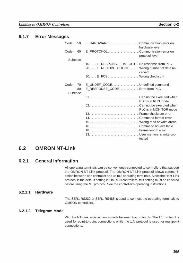
205
Linking to OMRON Controllers Section 6-2
6.1.7 Error MessagesCode 50 E HARDWARE . . . . . . . . . . . . . . . . . . . . .Communication error on
hardware levelCode 60 E PROTOKOL. . . . . . . . . . . . . . . . . . . . . .Communication error on
protocol levelSubcode
10. . . . . E RESPONSE TIMEOUT. . .No response from PLC20. . . . . E RECEIVE COUNT . . . . . . .Wrong number of data re-
ceived30. . . . . E FCS . . . . . . . . . . . . . . . . . . . . . .Wrong checksum
Code 70 E UNDEF CODE. . . . . . . . . . . . . . . . . . .Undefined command80 E RESPONSE CODE . . . . . . . . . . . . . .Error from PLC
Subcode01. . . . . . . . . . . . . . . . . . . . . . . . . . . . . . . . . . .Can not be executed when
PLC is in RUN mode02. . . . . . . . . . . . . . . . . . . . . . . . . . . . . . . . . . .Can not be executed when
PLC is in MONITOR mode13. . . . . . . . . . . . . . . . . . . . . . . . . . . . . . . . . . .Frame checksum error14. . . . . . . . . . . . . . . . . . . . . . . . . . . . . . . . . . .Command format error15. . . . . . . . . . . . . . . . . . . . . . . . . . . . . . . . . . .Wrong read or write areas16. . . . . . . . . . . . . . . . . . . . . . . . . . . . . . . . . . .Command not available18. . . . . . . . . . . . . . . . . . . . . . . . . . . . . . . . . . .Frame length error23. . . . . . . . . . . . . . . . . . . . . . . . . . . . . . . . . . .User memory is write-pro-
tected
6.2 OMRON NT-Link
6.2.1 General InformationAll operating terminals can be conveniently connected to controllers that supportthe OMRON NT-Link protocol. The OMRON NT-Link protocol allows communi-cation between one controller and up to 8 operating terminals. Since the Host-Linkprotocol is the default setting in OMRON controllers, this setting must be checkedbefore using the NT protocol. See the controller’s operating instructions.
6.2.1.1 Hardware
The SER1 RS232 or SER1 RS485 is used to connect the operating terminals toOMRON controllers.
6.2.1.2 Telegram Mode
With the NT-Link, a distinction is made between two protocols. The 1:1 protocol isused for point-to-point connections while the 1:N protocol is used for multipointconnections.
206
Linking to OMRON Controllers Section 6-2
6.2.1.3 Point-to-Point Connection
The 1:1 protocol is used for point-to-point connections. This means that only oneoperating terminal can be connected with one controller. Interfaces that can beused with this connection type are the RS232 or the RS422 / RS485 interface. A4-wire cable must be used in conjunction with the RS422 / RS485 interface.
6.2.1.4 Multipoint Connection
The 1:N protocol is used for multipoint connections. Up to 8 operating terminalscan be connected to one controller.The controller must be configured to address at least two operating terminals. Theconnection must be established using SER1 RS485. A 2-wire cable must be usedto ensure a sufficient termination.
6.2.2 Protocol Parameters
6.2.2.1 Parameters of SER1
Parameters that can be defined for SER1 are as follows.Different default values are predefined for the parameters depending on the proto-col.
1:1 NT-LinkBaud rate: 300, 600, 1200, 2400, 4800, 9600, 19200, 38400Data bits: 7, 8Parity: even, oddStop bits: 1, 2Handshake: no handshake
1:N NT-LinkBaud rate: 300, 600, 1200, 2400, 4800, 9600, 19200, 38400Data bits: 7, 8Parity: even, oddStop bits: 1, 2Handshake: no handshakeDefault values in the programming software are in bold print.
6.2.2.2 Additional Parameters
6.2.2.2.1 Parameter Maximum Waiting Time for Response
This parameter specifies the maximum time the operating terminal waits for a re-sponse from the PLC.The valid range of values is 50 ms to 65535 ms.The default value in the programming software is 500 ms.
207
Linking to OMRON Controllers Section 6-2
6.2.2.2.2 Parameter Delay until Connection Set-up
This parameter specifies the time the operating terminal waits before starting com-munication.The valid range of values is 5 s to 255 s.The default value in the programming software is 5 s.
6.2.2.2.3 Parameter NT Module Number
This parameter is used to set the NT module number for the operating terminal. Ifmultiple operating terminals are connected to one controller, then a separate num-ber must be specified for each operating terminal. Otherwise, a reliable communi-cation between the operating terminals and the controller is not possible.Valid values that can be specified as a NT module number range from 0 to 7.The default value is 0.The NT module number can also be set via the operating terminal by means of thesystem variable ComSlaveNr .
6.2.2.2.4 Parameter Protocol Mode
Selectable protocol modes are either 1:1 or 1:N. Ensure that this parameter and thesetting specified for the controller match.
6.2.2.2.5 Parameter Priority
This parameter applies only in conjunction with the 1:N protocol.If the priority is turned off, the master allocates the token sequentially to each sta-tion. If the parameter Priority is turned on, the master allocates every second tokento the operating terminal.
6.2.2.2.6 Parameter Duplex Operation
Select the parameter full duplex when using SER1 RS232.The parameter half duplex applies only in conjunction with SER1 RS485.
6.2.2.2.7 Parameter PLC Type
Different data types are permitted depending on the controller type. Therefore,select either the PLC type C-Series or CV-Series.
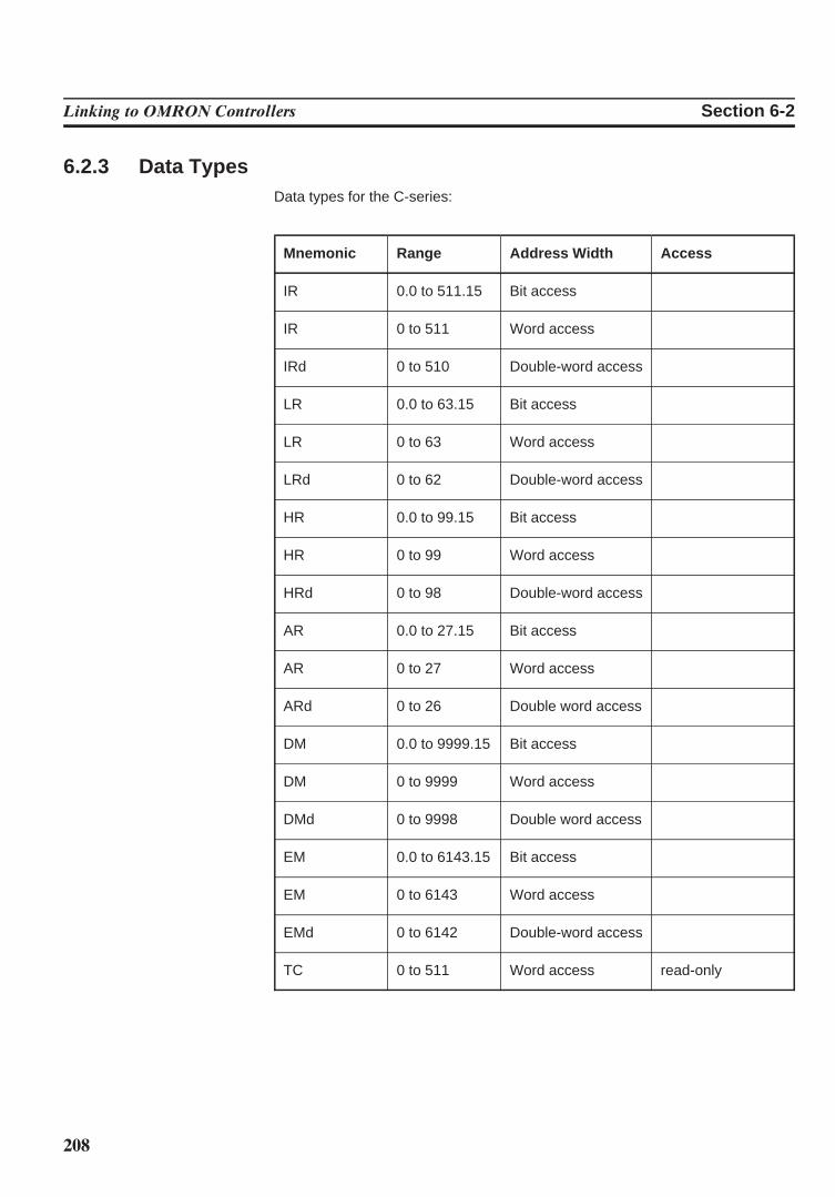
208
Linking to OMRON Controllers Section 6-2
6.2.3 Data TypesData types for the C-series:
Mnemonic Range Address Width Access
IR 0.0 to 511.15 Bit access
IR 0 to 511 Word access
IRd 0 to 510 Double-word access
LR 0.0 to 63.15 Bit access
LR 0 to 63 Word access
LRd 0 to 62 Double-word access
HR 0.0 to 99.15 Bit access
HR 0 to 99 Word access
HRd 0 to 98 Double-word access
AR 0.0 to 27.15 Bit access
AR 0 to 27 Word access
ARd 0 to 26 Double word access
DM 0.0 to 9999.15 Bit access
DM 0 to 9999 Word access
DMd 0 to 9998 Double word access
EM 0.0 to 6143.15 Bit access
EM 0 to 6143 Word access
EMd 0 to 6142 Double-word access
TC 0 to 511 Word access read-only
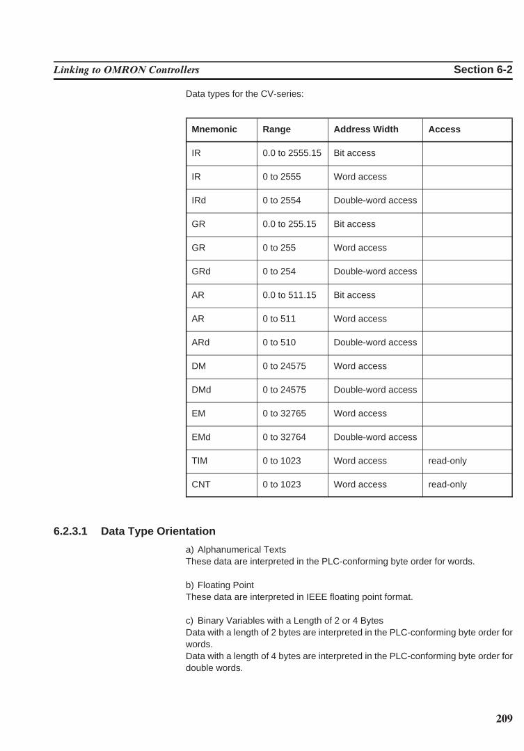
209
Linking to OMRON Controllers Section 6-2
Data types for the CV-series:
Mnemonic Range Address Width Access
IR 0.0 to 2555.15 Bit access
IR 0 to 2555 Word access
IRd 0 to 2554 Double-word access
GR 0.0 to 255.15 Bit access
GR 0 to 255 Word access
GRd 0 to 254 Double-word access
AR 0.0 to 511.15 Bit access
AR 0 to 511 Word access
ARd 0 to 510 Double-word access
DM 0 to 24575 Word access
DMd 0 to 24575 Double-word access
EM 0 to 32765 Word access
EMd 0 to 32764 Double-word access
TIM 0 to 1023 Word access read-only
CNT 0 to 1023 Word access read-only
6.2.3.1 Data Type Orientation
a) Alphanumerical TextsThese data are interpreted in the PLC-conforming byte order for words.
b) Floating PointThese data are interpreted in IEEE floating point format.
c) Binary Variables with a Length of 2 or 4 BytesData with a length of 2 bytes are interpreted in the PLC-conforming byte order forwords.Data with a length of 4 bytes are interpreted in the PLC-conforming byte order fordouble words.
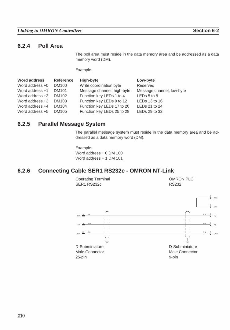
210
Linking to OMRON Controllers Section 6-2
6.2.4 Poll AreaThe poll area must reside in the data memory area and be addressed as a datamemory word (DM).
Example:
Word address Reference High-byte Low-byteWord address +0 DM100 Write coordination byte ReservedWord address +1 DM101 Message channel, high-byte Message channel, low-byteWord address +2 DM102 Function key LEDs 1 to 4 LEDs 5 to 8Word address +3 DM103 Function key LEDs 9 to 12 LEDs 13 to 16Word address +4 DM104 Function key LEDs 17 to 20 LEDs 21 to 24Word address +5 DM105 Function key LEDs 25 to 28 LEDs 29 to 32
6.2.5 Parallel Message SystemThe parallel message system must reside in the data memory area and be ad-dressed as a data memory word (DM).
Example:Word address + 0 DM 100Word address + 1 DM 101
6.2.6 Connecting Cable SER1 RS232c - OMRON NT-LinkOperating Terminal OMRON PLCSER1 RS232c RS232
25 G NG N D
18 B NR D
6 W HT D
2B NT D
9G NG N D
3W HR D
5C T S
4R T S
D-Subminiature D-SubminiatureMale Connector Male Connector25-pin 9-pin
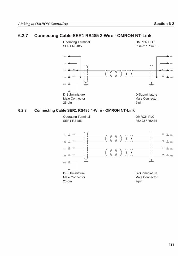
211
Linking to OMRON Controllers Section 6-2
6.2.7 Connecting Cable SER1 RS485 2-Wire - OMRON NT-LinkOperating Terminal OMRON PLCSER1 RS485 RS422 / RS485
2B NS D B
1W HS D A
11G N D
1
RD-23 B N
22 W HR D +
8TD+
9TD-
6R D A
8R D B
D-Subminiature D-SubminiatureMale Connector Male Connector25-pin 9-pin
6.2.8 Connecting Cable SER1 RS485 4-Wire - OMRON NT-Link
Operating Terminal OMRON PLCSER1 RS485 RS422 / RS485
2B NS D B
1W HS D A
11G N D
1
RD-23 B N
22 W HR D +
9 YETD-
8 G NTD+
6G NR D A
8YER D B
D-Subminiature D-SubminiatureMale Connector Male Connector25-pin 9-pin
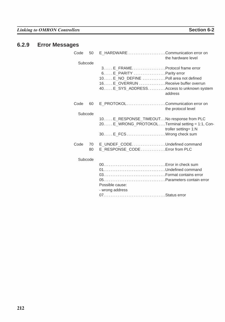
212
Linking to OMRON Controllers Section 6-2
6.2.9 Error MessagesCode 50 E HARDWARE . . . . . . . . . . . . . . . . . . . . .Communication error on
the hardware levelSubcode
3. . . . . E FRAME. . . . . . . . . . . . . . . . . . .Protocol frame error6. . . . . E PARITY . . . . . . . . . . . . . . . . . .Parity error
10. . . . . E NO DEFINE . . . . . . . . . . . . .Poll area not defined16. . . . . E OVERRUN . . . . . . . . . . . . . . .Receive buffer overrun40. . . . . E SYS ADDRESS. . . . . . . . . .Access to unknown system
address
Code 60 E PROTOKOL. . . . . . . . . . . . . . . . . . . . . .Communication error onthe protocol level
Subcode10. . . . . E RESPONSE TIMEOUT. . .No response from PLC20. . . . . E WRONG PROTOKOL. . . .Terminal setting = 1:1, Con-
troller setting= 1:N30. . . . . E FCS . . . . . . . . . . . . . . . . . . . . . .Wrong check sum
Code 70 E UNDEF CODE. . . . . . . . . . . . . . . . . . .Undefined command80 E RESPONSE CODE . . . . . . . . . . . . . .Error from PLC
Subcode00. . . . . . . . . . . . . . . . . . . . . . . . . . . . . . . . . . .Error in check sum01. . . . . . . . . . . . . . . . . . . . . . . . . . . . . . . . . . .Undefined command03. . . . . . . . . . . . . . . . . . . . . . . . . . . . . . . . . . .Format contains error05. . . . . . . . . . . . . . . . . . . . . . . . . . . . . . . . . . .Parameters contain errorPossible cause:- wrong address07. . . . . . . . . . . . . . . . . . . . . . . . . . . . . . . . . . .Status error
213
INDEX
AApplication Memory . . . . . . . . . . . . . . . . . . . . . . . . . . . . 43Authorization levels. . . . . . . . . . . . . . . . . . . . . . . . . . . . . 66
BBattery. . . . . . . . . . . . . . . . . . . . . . . . . . . . . . . . . . . . . . . . . 42
CCharacter Attributes . . . . . . . . . . . . . . . . . . . . . . . . . . . . 39Configuration mask . . . . . . . . . . . . . . . . . . 147, 188, 190Control Keys . . . . . . . . . . . . . . . . . . . . . . . . . . . . . . . . . . . 10Cursor down . . . . . . . . . . . . . . . . . . . . . . . . . . . . . . . . . . . 10Cursor home . . . . . . . . . . . . . . . . . . . . . . . . . . . . . . . . . . . 10Cursor left. . . . . . . . . . . . . . . . . . . . . . . . . . . . . . . . . . . . . . 10Cursor right . . . . . . . . . . . . . . . . . . . . . . . . . . . . . . . . . . . . 10Cursor up . . . . . . . . . . . . . . . . . . . . . . . . . . . . . . . . . . . . . . 10
DDIP switch S4 . . . . . . . . . . . . . . . . . . . . . . . . . . . . . 181, 183Download cable . . . . . . . . . . . . . . . . . . . . . . . . . . . . . . . . 180
EError Message . . . . . . . . . . . . . . . . . . . . . . . . . . . . . . . . . 188Error messages . . . . . . . . . . . . . . . . . . . . . . . . . . . . . . . . 181Error messages . . . . . . . . . . . . . . . . . . . . . . . . . . . . . . . . 141
ADDRESS ERROR. . . . . . . . . . . . . . . . . . . . . . . . . . 141BYTECOUNT OVERFLOW . . . . . . . . . . . . . . . . . . 141CHECKSUM ERROR. . . . . . . . . . . . . . . . . . . . . . . . 141COMMUNICATION ERROR . . . . . . . . . . . . . . . . . 141DATASET STORAGE FAILURE . . . . . . . . . . . . . 145DIFFERENT DRIV VERS . . . . . . . . . . . . . . . . . . . . 142DIFFERENT MASK VERS . . . . . . . . . . . . . . . . . . . 142DOWNLOAD . . . . . . . . . . . . . . . . . . . . . . . . . . . . . . . . 143ERASE FLASH EPROM . . . . . . . . . . . . . . . . . . . . . 143!!!!! ERROR !!!!!. . . . . . . . . . . . . . . . . . . . . . . . . . . . . . 142FATAL ERROR . . . . . . . . . . . . . . . . . . . . . . . . . . . . . 145FIRMWARE NOT CONFORM . . . . . . . . . . . . . . . 145FLASH CHECKSUM ERROR . . . . . . . . . . . . . . . . 145FLASH IS ERASED . . . . . . . . . . . . . . . . . . . . . . . . . 143FLASH MEMORY FAILURE . . . . . . . . . . . . . . . . . 141FLASH NOT ERASEABLE. . . . . . . . . . . . . . . . . . . 144FORMAT ERROR . . . . . . . . . . . . . . . . . . . . . . . . . . . 141INITIALIZING MESSAGE BUFFER . . . . . . . . . . 143KEYBOARD ERROR . . . . . . . . . . . . . . . . . . . . . . . . 143MEMORY IS FLASH XXXXK . . . . . . . . . . . . . . . . 145NO FLASH EPROM . . . . . . . . . . . . . . . . . . . . . . . . . 144TERMINAL-TYP IS XXXX . . . . . . . . . . . . . . . . . . . 145TURN POWER OFF. . . . . . . . . . . . . . . . . . . . . . . . . 142
UNEXPECTED INTERRUPT . . . . . . . . . . . . . . . . 144!!!!! WARNING!!!!! . . . . . . . . . . . . . . . . . . . . . . . . . . . 142WRONG S3-FILE . . . . . . . . . . . . . . . . . . . . . . . . . . . 144
External data release . . . . . . . . . . . . . . . . . . . . . . . . . . . 121
FFirmware. . . . . . . . . . . . . . . . . . . . . . . . . . . . . . . . . . . . . . . 180Formatted output of variables . . . . . . . . . . . . . . . . . . . 73Formula for scaling input values . . . . . . . . . . . . . . . . 84Formula for scaling the output of variables. . . . . . . 75Front Panel Dimensions . . . . . . . . . . . . . . . . . . . . . . . . 23
NT15S-SF121B-E . . . . . . . . . . . . . . . . . . . . . . . . . . . 23NT18S-SF121B-E . . . . . . . . . . . . . . . . . . . . . . . . . . . 24NT4S-SF122B-E . . . . . . . . . . . . . . . . . . . . . . . . . . . . 22NT4S-SF123B-E . . . . . . . . . . . . . . . . . . . . . . . . . . . . 23
Front View . . . . . . . . . . . . . . . . . . . . . . . . . . . . . . . . . . . . . 7NT15S-SF121B-E . . . . . . . . . . . . . . . . . . . . . . . . . . . 7NT18S-SF121B-E . . . . . . . . . . . . . . . . . . . . . . . . . . . 8NT4S-SF122B-E . . . . . . . . . . . . . . . . . . . . . . . . . . . . 5NT4S-SF123B-E . . . . . . . . . . . . . . . . . . . . . . . . . . . . 6
Function Key Arrangement . . . . . . . . . . . . . . . . . . . . . 13NT15S-SF121B-E . . . . . . . . . . . . . . . . . . . . . . . . . . . 13NT18S-SF121B-E . . . . . . . . . . . . . . . . . . . . . . . . . . . 13
Fuse . . . . . . . . . . . . . . . . . . . . . . . . . . . . . . . . . . . . . . . . . . . 43
HHelp key . . . . . . . . . . . . . . . . . . . . . . . . . . . . . . . . . . . . . . . 115Help text . . . . . . . . . . . . . . . . . . . . . . . . . . . . . . . . . . . . . . . 84
for input variables . . . . . . . . . . . . . . . . . . . . . . . . . . . 84
IInput variable . . . . . . . . . . . . . . . . . . . . . . . . . . . . . . . . . . 84
Counter . . . . . . . . . . . . . . . . . . . . . . . . . . . . . . . . . . . . . 84Timer . . . . . . . . . . . . . . . . . . . . . . . . . . . . . . . . . . . . . . . 83
Interface Parameters . . . . . . . . . . . . . . . . . . . . . . . . . . . 188
KKey . . . . . . . . . . . . . . . . . . . . . . . . . . . . . . . . . . . . . . . . . . . . 115
Data Release . . . . . . . . . . . . . . . . . . . . . . . . . . . . . . . 115Key functions . . . . . . . . . . . . . . . . . . . . . . . . . . . . . . . . . . 119
editor for coded text . . . . . . . . . . . . . . . . . . . . . . . . . 119Key functions in the alphanumerical editor. . . . . . . 118Key functions in the BCD-number editor. . . . . . . . . 117Key functions in the hexadecimal editor . . . . . . . . . 118
in the I/O mask . . . . . . . . . . . . . . . . . . . . . . . . . . . . . . 72Key functions in the numerical editor . . . . . . . . . . . . 116
214
Index
MMarginal conditions. . . . . . . . . . . . . . . . . . . . . . . . . . . . . 169Mask number . . . . . . . . . . . . . . . . . . . . . . . . . . . . . . . . . . 164Mask types. . . . . . . . . . . . . . . . . . . . . . . . . . . . . . . . . . . . . 70Master password . . . . . . . . . . . . . . . . . . . . . . . . . . . . . . . 68Mode selector switch . . . . . . . . . . . . . . . . . . . . . . . . . . . 63
Standard Mode. . . . . . . . . . . . . . . . . . . . . . . . . . . . . . 63
NNumber of languages. . . . . . . . . . . . . . . . . . . . . . . . . . . 178
OOne-time output variables/cyclic output variables 73
PPassword editor . . . . . . . . . . . . . . . . . . . . . . . . . . . . . . . . 118Password protection. . . . . . . . . . . . . . . . . . . . . . . . . . . . 66
access level . . . . . . . . . . . . . . . . . . . . . . . . . . . . . . . . . 66authorization level . . . . . . . . . . . . . . . . . . . . . . . . . . . 66setup mask. . . . . . . . . . . . . . . . . . . . . . . . . . . . . . . . . . 68view level . . . . . . . . . . . . . . . . . . . . . . . . . . . . . . . . . 67, 68
Pin assignment. . . . . . . . . . . . . . . . . . . . . . . . . . . . . . . . . 32Plausibility . . . . . . . . . . . . . . . . . . . . . . . . . . . . . . . . . . . . . 115Plausibility check . . . . . . . . . . . . . . . . . . . . . . . . . . . . . . . 84
input variable. . . . . . . . . . . . . . . . . . . . . . . . . . . . . . . . 84Position of the Switch for Transparent Mode. . . . . 187Post-decimal places . . . . . . . . . . . . . . . . . . . . . . . . . . . . 73
RRange of values . . . . . . . . . . . . . . . . . . . . . . . . . . . . . 72, 73Refresh intervals . . . . . . . . . . . . . . . . . . . . . . . . . . . . . . . 180Representation of output variables . . . . . . . . . . . . . . 75Representation with leading zeros . . . . . . . . . . . . . . 75Running time meter . . . . . . . . . . . . . . . . . . . . . . . . . . . . 162
reset byte . . . . . . . . . . . . . . . . . . . . . . . . . . . . . . . . . . . 162
SScaled output of variables . . . . . . . . . . . . . . . . . . . . . . 74SETUP DATA . . . . . . . . . . . . . . . . . . . . . . . . . . . . . . . . . . 189Side View . . . . . . . . . . . . . . . . . . . . . . . . . . . . . . . . . . . . . . 27
NT15S-SF121B-E . . . . . . . . . . . . . . . . . . . . . . . . . . . 27NT18S-SF121B-E . . . . . . . . . . . . . . . . . . . . . . . . . . . 28NT4S-SF122B-E . . . . . . . . . . . . . . . . . . . . . . . . . . . . 25NT4S-SF123B-E . . . . . . . . . . . . . . . . . . . . . . . . . . . . 26
Slide-in Identification Strips for the Function Keys 15NT15S-SF121B-E . . . . . . . . . . . . . . . . . . . . . . . . . . . 15NT18S-SF121B-E . . . . . . . . . . . . . . . . . . . . . . . . . . . 15NT4S-SF122B-E . . . . . . . . . . . . . . . . . . . . . . . . . . . . 14NT4S-SF123B-E . . . . . . . . . . . . . . . . . . . . . . . . . . . . 15
Special Keys . . . . . . . . . . . . . . . . . . . . . . . . . . . . . . . . . . . 10Status LED. . . . . . . . . . . . . . . . . . . . . . . . . . . . . . . . . . . . . 121
data release. . . . . . . . . . . . . . . . . . . . . . . . . . . . . . . . . 121Symbolic name. . . . . . . . . . . . . . . . . . . . . . . . . . . . . . . . . 164System message. . . . . . . . . . . . . . . . . . . . . . . . . . . . . . . 139
data set active. . . . . . . . . . . . . . . . . . . . . . . . . . . . . . . 139data set download . . . . . . . . . . . . . . . . . . . . . . . . . . . 140data set file error . . . . . . . . . . . . . . . . . . . . . . . . . . . . 139data set format . . . . . . . . . . . . . . . . . . . . . . . . . . . . . . 140data set memory full . . . . . . . . . . . . . . . . . . . . . . . . . 139data set protected . . . . . . . . . . . . . . . . . . . . . . . . . . . 139data set transfer . . . . . . . . . . . . . . . . . . . . . . . . . . . . . 139data set unknown. . . . . . . . . . . . . . . . . . . . . . . . . . . . 139editing mode active . . . . . . . . . . . . . . . . . . . . . . . . . . 139
system message . . . . . . . . . . . . . . . . . . . . . . . . . . . . . . . 139illegal data set . . . . . . . . . . . . . . . . . . . . . . . . . . . . . . . 139
System message. . . . . . . . . . . . . . . . . . . . . . . . . . . . . . . 139interface in use . . . . . . . . . . . . . . . . . . . . . . . . . . . . . . 139invalid mask no. . . . . . . . . . . . . . . . . . . . . . . . . . . . . . 138invalid message no . . . . . . . . . . . . . . . . . . . . . . . . . . 138invalid password. . . . . . . . . . . . . . . . . . . . . . . . . . . . . 139loop-through active . . . . . . . . . . . . . . . . . . . . . . . . . . 140message buffer full . . . . . . . . . . . . . . . . . . . . . . . . . . 138message overflow . . . . . . . . . . . . . . . . . . . . . . . . . . . 138new message . . . . . . . . . . . . . . . . . . . . . . . . . . . . . . . 138no data set address . . . . . . . . . . . . . . . . . . . . . . . . . 140overvoltage . . . . . . . . . . . . . . . . . . . . . . . . . . . . . . . . . 139password missing . . . . . . . . . . . . . . . . . . . . . . . . . . . 139password unchanged . . . . . . . . . . . . . . . . . . . . . . . . 139print log invalid . . . . . . . . . . . . . . . . . . . . . . . . . . . . . . 138recipe unknown . . . . . . . . . . . . . . . . . . . . . . . . . . . . . 140replace battery . . . . . . . . . . . . . . . . . . . . . . . . . . . . . . 138value too large . . . . . . . . . . . . . . . . . . . . . . . . . . . . . . 138value too small . . . . . . . . . . . . . . . . . . . . . . . . . . . . . . 138wrong format . . . . . . . . . . . . . . . . . . . . . . . . . . . . . . . . 138(floating point) number invalid . . . . . . . . . . . . . . . . 140
System numbers . . . . . . . . . . . . . . . . . . . . . . . . . . . . . . . 137System variables . . . . . . . . . . . . . . . . . . . . . . . . . . . . . . . 86
basic functions . . . . . . . . . . . . . . . . . . . . . . . . . . . . . . 86Boot. . . . . . . . . . . . . . . . . . . . . . . . . . . . . . . . . . . . . . 86ComVersion . . . . . . . . . . . . . . . . . . . . . . . . . . . . . . 85handshake . . . . . . . . . . . . . . . . . . . . . . . . . . . . . . . 172IntEraseEprom . . . . . . . . . . . . . . . . . . . . . . . . . . . 85LCDBackground. . . . . . . . . . . . . . . . . . . . . . . . . . 86LCDBackLight . . . . . . . . . . . . . . . . . . . . . . . . . . . . 86LCDContrast . . . . . . . . . . . . . . . . . . . . . . . . . . . . . 86MainVersion. . . . . . . . . . . . . . . . . . . . . . . . . . . . . . 85OsLanguage . . . . . . . . . . . . . . . . . . . . . . . . . . . . . 87TurnOnTemp . . . . . . . . . . . . . . . . . . . . . . . . . . . . . 87UserVersion . . . . . . . . . . . . . . . . . . . . . . . . . . . . . . 86
communication area X2. . . . . . . . . . . . . . . . . . . . . . 88ComBaudrateA . . . . . . . . . . . . . . . . . . . . . . . . . . . 88ComDataLenA. . . . . . . . . . . . . . . . . . . . . . . . . . . . 87ComDefaultA . . . . . . . . . . . . . . . . . . . . . . . . . . . . . 88
215
Index
ComHandshakeA. . . . . . . . . . . . . . . . . . . . . . . . . 88ComParityA . . . . . . . . . . . . . . . . . . . . . . . . . . . . . . 87
communication area x2 . . . . . . . . . . . . . . . . . . . . . . 89ComRetryTimeout . . . . . . . . . . . . . . . . . . . . . . . . 89
communication area X2. . . . . . . . . . . . . . . . . . . . . . 89ComSlaveNr . . . . . . . . . . . . . . . . . . . . . . . . . . . . . 89ComStopBitsA. . . . . . . . . . . . . . . . . . . . . . . . . . . . 88ComTimeout . . . . . . . . . . . . . . . . . . . . . . . . . . . . . 89
communication area X3. . . . . . . . . . . . . . . . . . . . . . 91ComBaudrateB . . . . . . . . . . . . . . . . . . . . . . . . . . . 91ComDataLenB. . . . . . . . . . . . . . . . . . . . . . . . . . . . 90ComDefaultB . . . . . . . . . . . . . . . . . . . . . . . . . . . . . 91ComHandshakeB. . . . . . . . . . . . . . . . . . . . . . . . . 91ComParityB . . . . . . . . . . . . . . . . . . . . . . . . . . . . . . 91ComStopBitsB. . . . . . . . . . . . . . . . . . . . . . . . . . . . 91
editors . . . . . . . . . . . . . . . . . . . . . . . . . . . . . . . . . . . . . . 114EditEnter . . . . . . . . . . . . . . . . . . . . . . . . . . . . . . . . . 114EditInvers . . . . . . . . . . . . . . . . . . . . . . . . . . . . . . . . 114StatePerm. . . . . . . . . . . . . . . . . . . . . . . . . . . . . . . . 114
error statistics interface X2. . . . . . . . . . . . . . . . . . . 90ComErrorTab. . . . . . . . . . . . . . . . . . . . . . . . . . . . . 90ComFrameCount . . . . . . . . . . . . . . . . . . . . . . . . . 90ComOverrunCount . . . . . . . . . . . . . . . . . . . . . . . 89ComParityCount . . . . . . . . . . . . . . . . . . . . . . . . . . 89ComStatisticsTab. . . . . . . . . . . . . . . . . . . . . . . . . 90ComSubcodeTab. . . . . . . . . . . . . . . . . . . . . . . . . 90
help. . . . . . . . . . . . . . . . . . . . . . . . . . . . . . . . . . . . . . . . . 114Message . . . . . . . . . . . . . . . . . . . . . . . . . . . . . . . . . 114QuitMessage . . . . . . . . . . . . . . . . . . . . . . . . . . . . . 115StateHelp . . . . . . . . . . . . . . . . . . . . . . . . . . . . . . . . 114
loadable font . . . . . . . . . . . . . . . . . . . . . . . . . . . . . . . . 113ChrsetName. . . . . . . . . . . . . . . . . . . . . . . . . . . . . . 113
loop-through operation. . . . . . . . . . . . . . . . . . . . . . . 112Pg2Sps . . . . . . . . . . . . . . . . . . . . . . . . . . . . . . . . . . 112Pg2SpsState . . . . . . . . . . . . . . . . . . . . . . . . . . . . . 112
maintenance . . . . . . . . . . . . . . . . . . . . . . . . . . . . . . . . 113Break . . . . . . . . . . . . . . . . . . . . . . . . . . . . . . . . . . . . 113LCDADCInput . . . . . . . . . . . . . . . . . . . . . . . . . . . . 113LCDADCOutput . . . . . . . . . . . . . . . . . . . . . . . . . . 113User1 . . . . . . . . . . . . . . . . . . . . . . . . . . . . . . . . . . . . 113User2 . . . . . . . . . . . . . . . . . . . . . . . . . . . . . . . . . . . . 113User3 . . . . . . . . . . . . . . . . . . . . . . . . . . . . . . . . . . . . 113User4 . . . . . . . . . . . . . . . . . . . . . . . . . . . . . . . . . . . . 113User5 . . . . . . . . . . . . . . . . . . . . . . . . . . . . . . . . . . . . 113
menu control / keys. . . . . . . . . . . . . . . . . . . . . . . . . . 99HardCopy . . . . . . . . . . . . . . . . . . . . . . . . . . . . . . . . 99KeyClear . . . . . . . . . . . . . . . . . . . . . . . . . . . . . . . . . 103KeyCursDown . . . . . . . . . . . . . . . . . . . . . . . . . . . . 102KeyCursLeft . . . . . . . . . . . . . . . . . . . . . . . . . . . . . . 101KeyCursRight . . . . . . . . . . . . . . . . . . . . . . . . . . . . 102KeyCursUp. . . . . . . . . . . . . . . . . . . . . . . . . . . . . . . 102KeyDot . . . . . . . . . . . . . . . . . . . . . . . . . . . . . . . . . . . 103
KeyEdit . . . . . . . . . . . . . . . . . . . . . . . . . . . . . . . . . . 105KeyEnter . . . . . . . . . . . . . . . . . . . . . . . . . . . . . . . . . 105KeyHelp. . . . . . . . . . . . . . . . . . . . . . . . . . . . . . . . . . 102KeyHome . . . . . . . . . . . . . . . . . . . . . . . . . . . . . . . . 102KeyMinus . . . . . . . . . . . . . . . . . . . . . . . . . . . . . . . . 105KeyPlus . . . . . . . . . . . . . . . . . . . . . . . . . . . . . . . . . . 105Key0 . . . . . . . . . . . . . . . . . . . . . . . . . . . . . . . . . . . . . 103Key1 . . . . . . . . . . . . . . . . . . . . . . . . . . . . . . . . . . . . . 103Key2 . . . . . . . . . . . . . . . . . . . . . . . . . . . . . . . . . . . . . 103Key3 . . . . . . . . . . . . . . . . . . . . . . . . . . . . . . . . . . . . . 104Key4 . . . . . . . . . . . . . . . . . . . . . . . . . . . . . . . . . . . . . 104Key5 . . . . . . . . . . . . . . . . . . . . . . . . . . . . . . . . . . . . . 104Key6 . . . . . . . . . . . . . . . . . . . . . . . . . . . . . . . . . . . . . 104Key7 . . . . . . . . . . . . . . . . . . . . . . . . . . . . . . . . . . . . . 104Key8 . . . . . . . . . . . . . . . . . . . . . . . . . . . . . . . . . . . . . 105Key9 . . . . . . . . . . . . . . . . . . . . . . . . . . . . . . . . . . . . . 105NewMask . . . . . . . . . . . . . . . . . . . . . . . . . . . . . . . . 99Shift. . . . . . . . . . . . . . . . . . . . . . . . . . . . . . . . . . . . . . 100ShiftCase . . . . . . . . . . . . . . . . . . . . . . . . . . . . . . . . 101TabLeft. . . . . . . . . . . . . . . . . . . . . . . . . . . . . . . . . . . 100TabPgDn. . . . . . . . . . . . . . . . . . . . . . . . . . . . . . . . . 100TabPgUp. . . . . . . . . . . . . . . . . . . . . . . . . . . . . . . . . 100TabRight . . . . . . . . . . . . . . . . . . . . . . . . . . . . . . . . . 100VarTablenR0 . . . . . . . . . . . . . . . . . . . . . . . . . . . . . 99VarTablenR1 . . . . . . . . . . . . . . . . . . . . . . . . . . . . . 99
parallel message system. . . . . . . . . . . . . . . . . . . . . 96RepmanSortCritP. . . . . . . . . . . . . . . . . . . . . . . . . 96RepoutAnzYearP . . . . . . . . . . . . . . . . . . . . . . . . . 97RepoutDateP. . . . . . . . . . . . . . . . . . . . . . . . . . . . . 96RepoutNrP . . . . . . . . . . . . . . . . . . . . . . . . . . . . . . . 96RepoutRepTextP . . . . . . . . . . . . . . . . . . . . . . . . . 97RepoutRepTextP21. . . . . . . . . . . . . . . . . . . . . . . 97RepoutRepTextP41. . . . . . . . . . . . . . . . . . . . . . . 97RepoutRepTextP61. . . . . . . . . . . . . . . . . . . . . . . 97RepoutTimeP . . . . . . . . . . . . . . . . . . . . . . . . . . . . 96
password . . . . . . . . . . . . . . . . . . . . . . . . . . . . . . . . . . . 106ChangePasswd. . . . . . . . . . . . . . . . . . . . . . . . . . . 106FlashPasswd . . . . . . . . . . . . . . . . . . . . . . . . . . . . . 106MskchgPasswd. . . . . . . . . . . . . . . . . . . . . . . . . . . 106MskchgResPasswd. . . . . . . . . . . . . . . . . . . . . . . 106Passwdlnactive . . . . . . . . . . . . . . . . . . . . . . . . . . . 106
password protection . . . . . . . . . . . . . . . . . . . . . . . . . 66edit level . . . . . . . . . . . . . . . . . . . . . . . . . . . . . . . . . 66
printer control . . . . . . . . . . . . . . . . . . . . . . . . . . . . . . . 98BlockPrint . . . . . . . . . . . . . . . . . . . . . . . . . . . . . . . . 98BlockPrintLong . . . . . . . . . . . . . . . . . . . . . . . . . . . 99PrintAllRep . . . . . . . . . . . . . . . . . . . . . . . . . . . . . . . 98PrintAllState . . . . . . . . . . . . . . . . . . . . . . . . . . . . . . 98StopPrint . . . . . . . . . . . . . . . . . . . . . . . . . . . . . . . . . 98
real-time clock. . . . . . . . . . . . . . . . . . . . . . . . . . . . . . . 93RTCDateFmt . . . . . . . . . . . . . . . . . . . . . . . . . . . . . 93RTCDay. . . . . . . . . . . . . . . . . . . . . . . . . . . . . . . . . . 92
216
Index
RTCDayofWeek . . . . . . . . . . . . . . . . . . . . . . . . . . 93RTCHour. . . . . . . . . . . . . . . . . . . . . . . . . . . . . . . . . 92RTCMin . . . . . . . . . . . . . . . . . . . . . . . . . . . . . . . . . . 92RTCMonth . . . . . . . . . . . . . . . . . . . . . . . . . . . . . . . 92RTCSec. . . . . . . . . . . . . . . . . . . . . . . . . . . . . . . . . . 92RTCYear . . . . . . . . . . . . . . . . . . . . . . . . . . . . . . . . . 93RTCYear2000 . . . . . . . . . . . . . . . . . . . . . . . . . . . . 93
recipes . . . . . . . . . . . . . . . . . . . . . . . . . . . . . . . . . . . . . . 108ActDSName . . . . . . . . . . . . . . . . . . . . . . . . . . . . . . 108DestDSNr . . . . . . . . . . . . . . . . . . . . . . . . . . . . . . . . 107DSCopy . . . . . . . . . . . . . . . . . . . . . . . . . . . . . . . . . . 107DSDelete. . . . . . . . . . . . . . . . . . . . . . . . . . . . . . . . . 108DSDnloadBreak . . . . . . . . . . . . . . . . . . . . . . . . . . 108DSDnloadState . . . . . . . . . . . . . . . . . . . . . . . . . . . 109DSDownload . . . . . . . . . . . . . . . . . . . . . . . . . . . . . 108LoadDSName . . . . . . . . . . . . . . . . . . . . . . . . . . . . 109RestoreLineNr. . . . . . . . . . . . . . . . . . . . . . . . . . . . 110RestoreState . . . . . . . . . . . . . . . . . . . . . . . . . . . . . 110RezPrintState . . . . . . . . . . . . . . . . . . . . . . . . . . . . 110SaveState . . . . . . . . . . . . . . . . . . . . . . . . . . . . . . . . 109SelectDSName . . . . . . . . . . . . . . . . . . . . . . . . . . . 107SelectDSNr . . . . . . . . . . . . . . . . . . . . . . . . . . . . . . 107SelectRezeptNr. . . . . . . . . . . . . . . . . . . . . . . . . . . 108StartRestore. . . . . . . . . . . . . . . . . . . . . . . . . . . . . . 110StartRezPrint . . . . . . . . . . . . . . . . . . . . . . . . . . . . . 110StartSave . . . . . . . . . . . . . . . . . . . . . . . . . . . . . . . . 109StartUpload . . . . . . . . . . . . . . . . . . . . . . . . . . . . . . 111UploadDSNr. . . . . . . . . . . . . . . . . . . . . . . . . . . . . . 111UploadState . . . . . . . . . . . . . . . . . . . . . . . . . . . . . . 111
running time meter . . . . . . . . . . . . . . . . . . . . . . . . . . 112Counter1 . . . . . . . . . . . . . . . . . . . . . . . . . . . . . . . . . 112Counter2 . . . . . . . . . . . . . . . . . . . . . . . . . . . . . . . . . 112Counter3 . . . . . . . . . . . . . . . . . . . . . . . . . . . . . . . . . 112Counter4 . . . . . . . . . . . . . . . . . . . . . . . . . . . . . . . . . 112Counter5 . . . . . . . . . . . . . . . . . . . . . . . . . . . . . . . . . 112Counter6 . . . . . . . . . . . . . . . . . . . . . . . . . . . . . . . . . 112Counter7 . . . . . . . . . . . . . . . . . . . . . . . . . . . . . . . . . 112Counter8 . . . . . . . . . . . . . . . . . . . . . . . . . . . . . . . . . 112
serial message system . . . . . . . . . . . . . . . . . . . . . . 94ClearRepBuf . . . . . . . . . . . . . . . . . . . . . . . . . . . . . 94RepmanRepPrint . . . . . . . . . . . . . . . . . . . . . . . . . 94RepmanSortCrit . . . . . . . . . . . . . . . . . . . . . . . . . . 93RepoutAnzYear . . . . . . . . . . . . . . . . . . . . . . . . . . 95RepoutDate . . . . . . . . . . . . . . . . . . . . . . . . . . . . . . 94RepoutNr. . . . . . . . . . . . . . . . . . . . . . . . . . . . . . . . . 94RepoutRepText. . . . . . . . . . . . . . . . . . . . . . . . . . . 95RepoutRepText21 . . . . . . . . . . . . . . . . . . . . . . . . 95RepoutRepText41 . . . . . . . . . . . . . . . . . . . . . . . . 95RepoutRepText61 . . . . . . . . . . . . . . . . . . . . . . . . 95RepoutTime . . . . . . . . . . . . . . . . . . . . . . . . . . . . . . 94
TTechnical Data . . . . . . . . . . . . . . . . . . . . . . . . . . . . . . . . . 51
NT15S-SF121B-E . . . . . . . . . . . . . . . . . . . . . . . . . . . 51NT18S-SF121B-E . . . . . . . . . . . . . . . . . . . . . . . . . . . 53NT4S-SF122B-E . . . . . . . . . . . . . . . . . . . . . . . . . . . . 48NT4S-SF123B-E . . . . . . . . . . . . . . . . . . . . . . . . . . . . 50
Transmission Parameters . . . . . . . . . . . . . . . . . . . . . . 188
UUser-Mode Switch. . . . . . . . . . . . . . . . . . . . . . . . . . . . . . 187
VVariable type . . . . . . . . . . . . . . . . . . . . . . . . . . . . . . . . . . . 72
ASCII . . . . . . . . . . . . . . . . . . . . . . . . . . . . . . . . . . . . . . . 72bit. . . . . . . . . . . . . . . . . . . . . . . . . . . . . . . . . . . . . . . . . . . 72byte. . . . . . . . . . . . . . . . . . . . . . . . . . . . . . . . . . . . . . . . . 72Lword . . . . . . . . . . . . . . . . . . . . . . . . . . . . . . . . . . . . . . . 72word . . . . . . . . . . . . . . . . . . . . . . . . . . . . . . . . . . . . . . . . 72
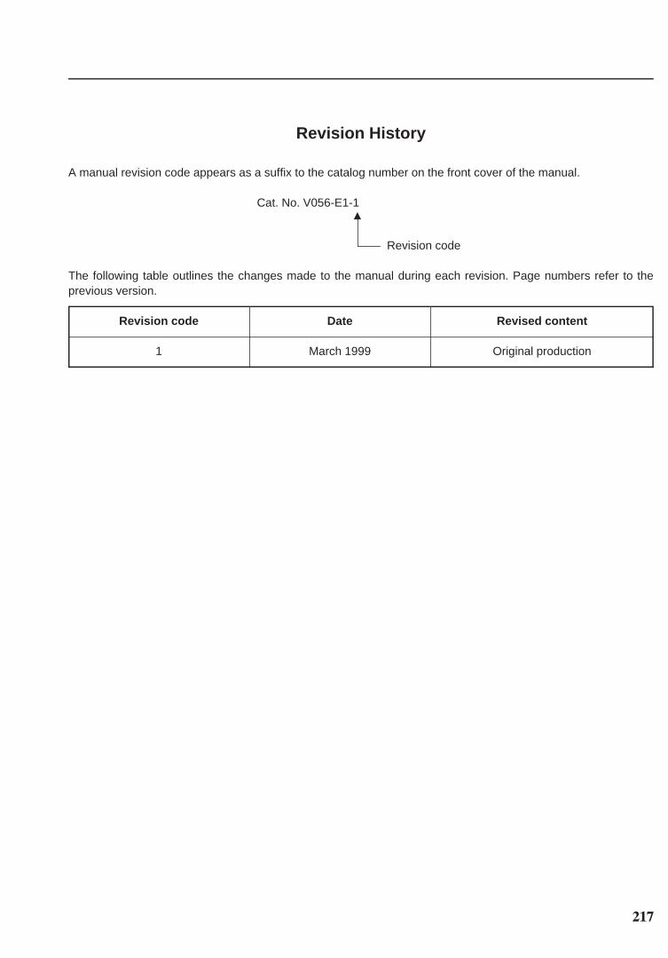
217
Revision History
A manual revision code appears as a suffix to the catalog number on the front cover of the manual.
Cat. No. V056-E1-1M
Revision code
The following table outlines the changes made to the manual during each revision. Page numbers refer to theprevious version.
Revision code Date Revised content
1 March 1999 Original production

Authorized Distributor:
Cat. No. V056-E1-1 Note: Specifications subject to change without notice. Printed in the Netherlands

Regional Headquarters
OMRON EUROPE B.V.
Wegalaan 67-69
NL-2132 JD Hoofddorp
The Netherlands
Tel: +31 (0)23 56 81 300
Fax: +31 (0)23 56 81 388