Embed Size (px)
Citation preview

SCC 600EHydraulic crawler crane
2 2
SCC600E Crawler Crane
Outline DimensionsTechnical Features
Performance ParametersTransportation Dimensions
Transportation Dimensions of luffi ng jib
Specifications
SuperstructureUndercarriageOperation DevicesSafety Devices
Operating Condition Combination
Operating Condition CombinationH Operating Condition
FJ Operating ConditionLuffi ng Jib LJ Operating Condition
content
P3
P11
P18
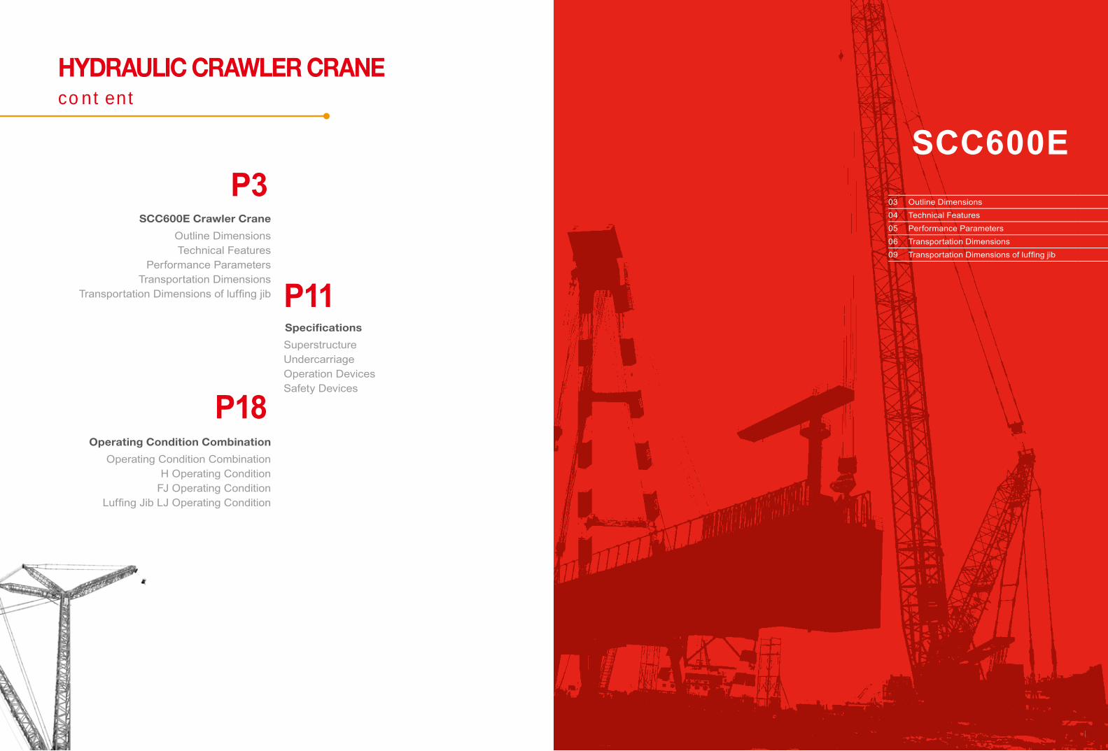
03 Outline Dimensions04 Technical Features05 Performance Parameters06 Transportation Dimensions09 Transportation Dimensions of luffi ng jib
SCC600E
HYDRAULIC CRAWLER CRANE

SANY HYdrAulic crAwler crANe SCC600E
4 3
Technical FeaturesOUTLINE dimensions
1. Highly Secured Control System:There are two operation modes, working and assembly for your convenience. It features with electronic level gauge, machine-leaving stop action, and emergency electr ical control, with complete set of safety and monitoring device. Load moment limiter is free of calibration, providing higher safety of the equipment, and less auxiliary operating time; slewing area limit device is optional, to improve the safety of the equipment;
2. Excellent Operating Performance:Maximum load regulation and electronic-over-hydraulic controls ensure smooth micro-movement and stable operation. A real-time queried electronic load chart is provided, more conveniently and quickly;
3. Reliable Function Assurance: The safety margin in structural design is sufficient; the advanced flow distribution system which is load independent is adopted to the hydraulic system. the key components like pumps, valves, motors,and reducers, etc. are reliable and stable. are also adopted to ensure system stability and reliability. The control system is fully capable to function stably in extreme weather, such as high-and-cold, high-temperature, and high plateau weather; sensor has a protection against lightning strike; the entire machine adopts the closed wiring way, with waterproof / dust-proof protective grade up to IP65; the machine passed the verification test of the strength that is higher above two times of that in industry, having high reliability;
4.Convenient Maintenance Access: It takes no more than 10min/person to adjust, no more than 30 min/person for daily maintenance and no more than 2h/person to repair the machine.GPS remote monitoring system is optional for easy maintenance and management.
5.Powerful Lifting Capacity:Wide-track chassis is design to ensure excellent overall and operating stability within 360°slewing range, with max. single line pull of main and auxiliary winch up to 6.5t, with max. lifting capacity of main boom of 60t×3.7m=222t·m. and with 52m main boom.
6.High-efficient operating speed:Outmost layer line speed of main and auxiliary lifting winches is 120m/min, and of luffing winch is 72m/min;
7.Flexible Configuration Combination: Free fall winch is optional for main and auxiliary lifting winches.
8.Optimized Transportation Programs: With telescopic crawler, the maximum transportation width of whole machine is 3.36m, ensuring it to be transported around freely.
5923
760
3324
1094
2737
900 4231
4500(3360 Extended/Retracted)

SANY HYDRAULIC CRAWLER CRANE SCC600E
6 5
Transportation DimensionsPerformance Parameters
Performance Parameters of SCC600E Crawler Crane
Performance Index Unit Parameter
Boom Operating Condition
Max. Rated Lifting Capacity t 60
Boom Length m 13~52
Boom Luffi ng Angle ° 30°~80°
Max. Rated Lifting Torque t•m 222
Fixed Jib Operating Condition
Max. Length Boom + Max. Length Jib m 43+15.25
Jib offset Angle ° 10°、30°
Luffi ng Jib Operating Condition
Max. lifting Capacity t 12.5
Max. lifting moment t•m 10.1t×14m
Max. Length Boom + Max. Length luffi ng jib m 40.3+28
Boom luffi ng angle ° 60°~90°
Jib luffi ng angle ° 15°~75°
Operating Speed
Rope Speed of Main and Auxiliary Winches* m/min 0~120 (third layer)
Rope Speed of Luffi ng Winches* m/min 0-50 (fourth layer) or 72(magnetic valve connected)
Slewing Speed* rpm 0~2
Traveling Speed* km/h 0~1.2
Engine Output Power/Rated Speed kW/ rpm 127/2000 EURO III (optional)129/2200 GB III
Transportation Parameter
Max. Transportation Weight of Single Piece (with chassis, boom base, without counterweight)
t
28.5 ( inc luding boom base, and undercarriage, b u t n o t i n c l u d i n g counterweight)
Transportation Dimension(Length×Width×Height) mm 7030×3360×3304
Other Parameter Average Ground Pressure MPa 0.059
Basic Machine(without track frame) ×1
Length(L) 5.92mWidth (B) 3.36mHeight (H) 3.43mWeight 27.5tBasic Machine(with track frame) ×1
Length(L) 10.4mWidth (B) 3.36mHeight (H) 3.43mWeight 28.5tBody (including boom base and main machine counterweight) ×1
Length(L) 11.8mWidth (B) 3.36mHeight (H) 3.43mWeight 46.5tCounterweight Tray ×1
Length(L) 3.324mWidth (B) 1.36mHeight (H) 0.67mWeight 6tRight Counterweight Blocks ×2
Length(L) 1.647mWidth (B) 1.36mHeight (H) 0.72mWeight 3tLeft Counterweight ×2
Length(L) 1.647mWidth (B) 1.36mHeight (H) 0.72mWeight 3tBoom Base ×1
Length(L) 6.65mWidth (B) 1.66mHeight (H) 1.40mWeight 1.2tBoom Tip ×1
Length (L) 6.88m Width (B) 1.48mHeight (H) 1.40mWeight 1.1t
L
B
L
B
L
B
L
H
L
B
L H
L
L
H
H
B
B
B
Notes:1. The item with * means that rope speed of main / auxiliary winch, rope speed of luffi ng winch, slewing and traveling speeds will change with the load2. The average ground pressure is only for reference and the actual ground pressure should be calculated based on the real working conditions.

SANY HYDRAULIC CRAWLER CRANE SCC600E
8 7
6t hook ×1
Length(L) 0.75m
Width(B) 0.3m
Height(H) 0.3m
Weight 0.16t
15t hook ×1
Length(L) 1.34m
Width(B) 0.6m
Height(H) 0.34m
Weight 0.29t
45 t hook ×1
Length(L) 1.52m
Width(B) 0.69m
Height(H) 0.37m
Weight 0.49t
60 t hook ×1
Length(L) 1.65m
Width(B) 0.69m
Height(H) 0.39m
Weight 0.66t
Transportation Dimensions
9m Boom Inserts ×2
Length (L) 9.1m
Width (B) 1.46m
Height (H) 1.58m
Weight 0.7t
6m Boom Insert ×3
Length (L) 6.1m
Width (B) 1.46m
Height (H) 1.58m
Weight 0.5t
3m Boom Insert ×1
Length (L) 3.1m
Width (B) 1.46m
Height (H) 1.58m
Weight 0.3t
Boom Extension ×1
Length (L) 1.35m
Width (B) 0.7m
Height (H) 0.66m
Weight 0.2t
Jib Base ×1
Length (L) 3.24m
Width (B) 0.6m
Height (H) 0.55m
Weight 0.2t
Jib Tip ×1
Length (L) 3.35m
Width (B) 0.6m
Height (H) 0.55m
Weight 0.2t
Jib Insert ×3
Length (L) 3.11m
Width (B) 0.62m
Height (H) 0.7m
Weight 0.1t
Transportation Dimensions
Notes:1. The transportation dimensions are not drawn to proportion. The
dimensions in the sketch are design value excluding packages.2. The weight is design value and there may be tiny difference due
to the manufacturing calibration3. After product upgrading, the actual weight is subjected to the
latest products.
L
B
L
B
L
B
LB
L
B
L
B
L
B
L
B
L
B
L
B
L
B

SANY HYDRAULIC CRAWLER CRANE SCC600E
10 9
Special Boom Back-stop under Tower Condition ×2
Length (L) 5.13m
Width (B) 0.32m
Height (H) 0.29m
Weight 0.32tSpecial Jib Fixed Frame under Tower Condition ×1
Length (L) 1.45m
Width (B) 0.56m
Height (H) 0.46m
Weight 0.07t
Transportation Dimensions of luffing jib
Special Boom Head Combination under Tower Condition ×1
Length (L) 3.46m
Width (B) 1.42m
Height (H) 1.39m
Weight 0.6tSpecial Mast Combination under Tower Condition ×1
Length (L) 4.958m
Width (B) 1.446m
Height (H) 0.795m
Weight 0.68t
Luffi ng Jib Base ×1
Length (L) 5.48m
Width (B) 0.97m
Height (H) 1.35m
Weight 0.35t
Luffi ng Jib Tip ×1
Length (L) 5.42m
Width (B) 0.84m
Height (H) 1.01m
Weight 0.40t
Luffi ng Jib 3m Insert ×2
Length (L) 3.08m
Width (B) 0.84m
Height (H) 1.02m
Weight 0.13t
Luffi ng Jib 6m Insert ×2
Length (L) 6.08m
Width (B) 0.99m
Height (H) 1.02m
Weight 0.24t9m Boom Insert under Tower Condition ×1
Length (L) 9.10m
Width (B) 1.91m
Height (H) 1.43m
Weight 1.02t
Transportation Dimensions of luffing jib
L
H
L
B
L
B
L
B
L
H
L
B
L
B
B H
L
B
LL
BB
L
B

SANY HYDRAULIC CRAWLER CRANE SCC600E
12 11
SANY HYDRAULIC CRAWLER CRANE SCC600E
11
BNO.1 Main and auxiliary winches
Rope speed of outmost working layer 0~120m/min
Diameter of the rope Φ20mm
Length of the main winch 180m
length of the auxiliary winch 130m
Rated single line pull 6.5t
Specifications /Superstructure
1)EngineTwo options of the engineEU Ⅲ standard
■ QSB6.7-C170, 6-cylinder, turbocharging & air-air intercooler
■ Displacement:6.7L ■ Rated Power:127KW/2000RPM ■ Max. Torque: 659N·m 1500RPM ■ Emission Standard: EURO III TPE ■ Fuel Tank Volume:400L
GB Ⅲ standard ■ QSB6.7-C170, 6-cylinder, turbocharging & air-air
intercooler ■ Displacement:6.7L ■ Rated Power:129KW/2200RPM ■ Max. Torque:800N·m 1500RPM ■ Emission Standard: CN 3 TPEM ■ Fuel Tank Volume:400L
2)Electrical Control System ■ The CAN bus techno logy is app l ied fo r data
communication between integrated moment intelligent control system and data recorder, and for saving the relevant data.
■ Display can show engine speed, fuel level, oi l pressure, servo pressure, wind speed, engine working time, weight of load lifted by crane, working radius, and lifting boom angle; electronic load chart has a real-time inquiry function, providing the convenient and quick inquiry; the complete fault self-diagnosis and inquiry system is provided, thus reducing the equipment fault handling time.
■ Slewing area limit device is optional, to improve the safety of the equipment; sensor has a protection against the lightning strike, thus further improving the safety of the equipment.
■ The entire machine adopts the closed wiring way, with waterproof / dust-proof protective grade up to IP6 and with longer life applied.
■ Sensor has a protection against the lightning strike, providing higher reliability.
3)Hydraulic System ■ Electrical proportion control system are adopted,
including main pump, main valve, joystick and motor reducer, which are eff icient, reliable, stable and energy-saving.
■ Advanced rotation and micro-movement performance and limit load regulation ensure smooth and stable operation.
4)Main and Auxiliary Hoisting Mechanisms ■ The winch drum is directly driven by winch motor
through reducer, and can rotate into two directions through the manipulation of luffi ng handle to carry out lifting and lowering actions of the hook.
■ Motor reducer of well-known brand is adopted for higher reliability and durability.
■ The drum design ensures the multi-layer winding is always in order.
■ Steel wire of well-known brand is adopted for higher reliability and durability.
■ Free fall is optional for main and auxiliary winches, ensuing the convenient operation, and reliable and stable performance.
SCC600ESuperstructure 12Undercarriage 14
Operation Devices 15Safety Devices 16

SANY HYdrAulic crAwler crANe SCC600E
14 13
NO.2 Luffing Mechanism
Rope speed of the outermost working layer (R)
0-72m/min (magnetic valve connected)
Wire rope diameter Φ16mm
Wire rope length of luffing winch
142m
Rated single line pull 3.7t
5)Luffing Mechanism ■ The winch drum is directly driven by luffing motor
through reducer, and can rotate into two directions through the manipulation of luffing handle to carry out lifting and lowering actions of the hook.
■ Motor reducer of well-known brand is adopted for higher reliability and durability.
■ The drum design ensures the multi-layer winding is always in order.
■ Steel wire of well-known brand is adopted for higher reliability and durability.
6)Swing Mechanism ■ The outer toothing swing drive can rotate 360° ■ Motor reducer of well-known brands is adopted for
higher reliability and durability. ■ Slewing lock: Pulling up the locking pin after the
completion of operation or during transportation can ensure the superstructure to be locked, which is convenient and reliable.
■ Slewing ring: single-row ball type slewing ring.
7)Counterweight ■ The superposable tray and counterweight blocks, and
new guide devices are easy to assembly, disassembly and transport. 3.3m overall width ensures more convenient transport and lower cost.
■ Standard Configuration: weight 18t, Composition: tray 6t×1, Counterweight block 3t×4
8)Cab ■ SANY’s newly designed cable features with artistic
styling and interior decoration, with large glass windows. There are short and long distance beam headlight, and rear-view mirror for more open vision. It is equipped with well ventilated air conditioning and radio. The seat, joystick and all control buttons are all ergonomically designed, which provides the operator with a more comfortable working environment.
■ Armrest box: Joystick, electric switch, emergency stop button and ignition lock are installed on left and right armrest box and auxiliary controlling box. The armrest box is adjustable with the seat.
■ Seat: Suspension, mult imode, and mult istage adjustable seat is adopted, with unloading switch applied.
■ Air conditioning provides heating and cooling air with optimized air duct and air outlet.
Undercarriage
1)Travelling DriveEach track frames has an independent traveling drive. The traveling motor drives the machine to achieve independent traveling and turning through drive wheel and reducer.
2)Travelling BrakeThe concealed, wet and spring loaded normally closed brake is adopted, with spring force for braking and oil pressure for release.
3)Telescopic CrawlerCrawler frame can be expanded and retracted through cylinder.
4)Crawler TensioningCrawler tension can be adjusted by using hydraulic jack to push guide wheel to adjust clearance between shims.
5)Track ShoesHigh strength alloy steel with higher durability.
6)Travelling Speed0~1.2km/h Empty loaded on hard and level ground).

SANY HYdrAulic crAwler crANe SCC600E
16 15
Operation Devices
1)Boom ■ Lattice structure; main chord made of high strength
structure steel; each section is connected with pins. ■ Basic boom: 6.5m boom tip and 6.5m boom base. ■ Insert: 3m×1, 6m×32, 9m×2. ■ Boom Length: 13m ~ 52m.
2)Fixed Jib ■ Lattice structure; main chord made of high strength
structure steel; each section is connected with pins. ■ Basic boom: 3.05m boom tip and 3.05m boom base; ■ Insert: 3.05m×3. ■ Jib Length: 6.1m~15.25m. ■ Longest boom + longest jib: 43m boom + 15.25m jib.
3)Luffing Jib ■ Lattice structure; main chord made of high strength
structure steel; each section is connected with pins. ■ Basic Boom: 6.5m boom tip and 6.5m boom base; ■ Insert: 3. m×2;6m×2. ■ Jib Length: 16m~28m. ■ Longest boom + longest jib: 40.3m boom + 28m jib.
4)Boom Extension ■ Welded structure; It is jointed with boom through pin
for auxiliary hook operation.
5)Hook ■ 60t hook ■ 45t hook ■ 15t hook ■ 6t ball hook
Notes: The above operation devices are complete configuration. The order contract shall prevail for specific configuration.
Safety Devices
1)Integrated moment intelligent control system
■ Standard configured SANY load moment limiter is free of calibration, ensuring the high safety and efficiency of the equipment construction.
■ Integrated moment intelligent control system can automatically detect the load weight, working radius, and lifting boom angle, and compare with the rated load capacity, actual load, working radius, and lifting boom angle. Under normal operation, it can it can automatically cut the crane action to dangerous direction, and has a black-box function to record the over-load information.
■ Composition: display, controller, angle sensing, and load sensor.
2)Assemble/Operation Mode Change Switch In assembly mode, over hoisting limiter, and load moment indicator will be bypassed for the assembly of the crane. In operation mode, all safety limit devices will function.
3)Emergency StopIn case of emergency, the operator can immediately shut down the entire machine by pressing the emergency stop button.
4)Main and Auxiliary Hoisting LimiterComposed of limit switch and hammer etc. on boom tip to prevent over hoisting of hook block. When the lifting hook is raised to a certain height, the limit switch will be activated. The buzzer on the control panel will alarm and the failure indicator will flash. The lifting operation of hook block will be automatically cut off.
5)Lowering Limiter of Main and Auxiliary WinchComposed of movement trigger device and proximity switches to prevent wire rope from being over-released. When the wire rope is released near the last three loops, limit switch will work. The system will alarm through buzzer, sending alarm information to the display and automatically stop the lowering of winches.
6)Function LockIf the function locking handle is not at proper position, all control handles will not function. It can prevent misuse and operational accident due to body impact when getting on or
off the cab.
7)Drum Locking DeviceThere are electrically controlled locking devices for main winch, auxiliary winch and luffing winch. The action can be done only after the button is turned to the release position to prevent misuse of handle, thus ensuring the parking safety of winch during idle.
8)Swing Locking DeviceIt can lock the machine at the front, back, left and right direction.
9)Boom Angle Limiter ■ When the boom angle is greater than 79°,. buzzer will
give an alarm and the boom operation will be cut off. This protection is controlled by load moment limiter and travel switch.
■ When boom angle is less than 30°, the system will alarm through buzzer and display alarm information in combined instrument to automatically stop boom lowering movement. This protection is controlled by load moment indicator automatically.

SANY HYDRAULIC CRAWLER CRANE SCC600E
18 17
10)Boom Back-stop DeviceComposed of nesting tubing and spring. It buffers the energy of boom backwards tilting by spring force to prevent the boom from tilting backwards.
11)Boom Angle IndicatorThe angle indicator device is fi xed on the boom base near the cab for convenient view of operator.
12)Hook LatchThere are baffl e on the hook to prevent the wire rope fall off.
13)Monitoring SystemRemote monitoring system is equipped for GPS positioning, GPRS data transfer, machine use inquiries, running data monitoring and analysis and remote fault diagnosis.
14)Three-color Load Alarm LightRed, Yellow and Green lights indicate loading situations in Real-Time. If the actual load is less than 90% of the rated load, the Green light will turn on. If the actual load is more than 90%, but less than 100% of the rated load, the Yellow light will turn on with intermittent sound alarm. If the actual load is 100% of the rated load, the Red light will turn on with continuous sound alarm. If the actual load is 100%of the rated load, then the system will immediately cease the operation of the crane.
15)Audio and Visual AlarmWhen the integrated moment intelligent control system is powered, audio and visual alarm will fl ash.
16)Slewing AlarmWhen the machine is traveling or slewing, the slewing lamp
will fl ash.
17)Illumination LightThe short-beam lamp at the front of cab, front angle adjustable far-beam lamp, cab lamp and other lighting device at night are equipped to improve the visibility of construction.
18)Rearview MirrorIt will be mounted at front of cab and at right platform handrail.
19)PharosIt is on the top of boom for altitude lightning.
20)AnemometerIt is on the top of boom to monitor the wind speed in real time and to transfer data to the display in cab.
18
19 Operating Condition Combination21 H Operating Condition24 FJ Operating Condition30 Luffi ng Jib LJ Operating Condition
SCC600E

SANY HYDRAULIC CRAWLER CRANE SCC600E
20 19
Operating Condition Combination
H Operating ConditionBoom 13m-52m
FJ Operating ConditionBoom 22m-43m
Fixed Jib 6.1m-15.25m
LJ Operating ConditionBoom22.3m~40.3m Luffi ng jib 16m~28m

SANY HYDRAULIC CRAWLER CRANE SCC600E
22 21
H Operating ConditionH Operating Condition Combination
Boom length Basic Boom Insert
m 6.5m base
6.5mtip 3m 6m 9m
13 1 1 - - -
16 1 1 1 - -
19 1 1 - 1 -
221 1 1 1 -
★ 1 1 - - 1
25 1 1 - 2 -
281 1 1 2 -
★ 1 1 - 1 1
311 1 1 1 1
★ 1 1 - - 2
341 1 1 3 -
★ 1 1 - 2 1
371 1 1 2 1
★ 1 1 - 1 2
401 1 1 1 2
★ 1 1 - 3 1
431 1 1 3 1
★ 1 1 - 2 2
46 1 1 1 2 2
49 1 1 - 3 2
52 1 1 1 3 2
Operating Range Diagram ofH Operating Condition
Notes: The boom combination remarked with ★ is optimized ;
6.5m boom base
6.5m boom
9m
9m
6m
6m
6m
3m
Liftin
g he
ight (
m)
Working radius (m)
55
50
45
40
35
30
25
20
15
0 0.9 5 10 15 20 25 30 34
34m
37m
40m
43m
46m
49m
52m50°
40°
30°
31m28m
25m22m
19m16m
13m
10
5
60°70°80°

SANY HYdrAulic crAwler crANe SCC600E
24 23
Boom Load Chart(H Operating Condition)
Radius(m)SCC600E Boom Rated Load Chart
13 16 19 22 25 28 31 34 37 40 43 46 49 52
3.7 60
4 50.2 48.2
4.5 42.5 41.8 40.2
5 37.5 36 35 33.2
5.5 32.5 31.9 31 30.2 28.2
6 28.5 28.3 27.5 27.2 26.2 25.2
7 22.9 22.7 22.5 22.2 21.7 21.2 20.5
8 19.2 19 18.7 18.5 18.5 18 17.5 17.1 16.7
9 16.1 15.7 15.7 15.6 15.5 15.4 14.8 14.2 14 13.2 12.8
10 14.2 14 13.9 13.9 13.7 13.7 13.5 13.2 12.8 12.5 12.1 11.7 11.3
12 11.3 11.2 11.1 11 10.9 10.8 10.8 10.5 10.3 10 9.6 9.3 9.2 9.2
14 9.3 9.2 9.1 9 8.8 8.8 8.6 8.5 8.2 8 7.7 7.4 7.4
16 7.8 7.7 7.6 7.5 7.4 7.2 7.1 6.9 6.9 6.4 6.2 6.2
18 6.6 6.6 6.6 6.5 6.4 6.2 6.1 5.9 5.8 5.5 5.3 5.1
20 5.6 5.6 5.5 5.5 5.3 5.2 4.9 4.9 4.7 4.4 4.3
22 5 4.8 4.6 4.5 4.3 4.2 4.1 3.9 3.7 3.6
24 4.2 4 3.9 3.7 3.6 3.5 3.3 3.2 3
26 3.6 3.6 3.4 3.3 3.2 3 2.9 2.7 2.5
28 3 3 2.9 2.7 2.5 2.4 2.3 2.1
30 2.6 2.5 2.3 2.1 2 1.9 1.7
32 2.1 2 1.8 1.7 1.6 1.4
34 1.8 1.7 1.5 1.4 1.3 1.2
36 1.3 1.1 1 0.9
unit:(t)
FJ Operating Condition
Notes-Rated Load of Crane1. The track frame shall be expanded during lifting.2. The rated load in the table is the value under the condition that the non-traveling heavy load is lifted slowly and steadily from the solid and
flat ground.3. The rated load in the table is calculated based on 75% of the tipping load under wind speed of less than 9.8m/s.4. All values in load chart are applicable for 360°rotation.5. The rated load value in the table includes the weight of hook, wire rope and other lifting tools. The actual hoisting capacity is value that the
rated value minus the weight of all lifting tools (including hooks, slings, and wire ropes). 6. The length of boom on which a jib can be mounted is 22m~43m. The max. length boom with an extension arm is 49m.
Fixed Jib Combination
Jib Length(m)Basic Boom Insert
Boom Length(m) Jib Offset Angle3.05m Base 3.05m Tip 3.05m
6.1 1 1 - 22~43 10°、30°9.15 1 1 1 22~43 10°、30°12.2 1 1 2 22~43 10°、30°15.25 1 1 3 22~43 10°、30°

SANY HYDRAULIC CRAWLER CRANE SCC600E
26 25
Operating Range Diagram of FJ Operating Condition
FJ Operating Condition Load Chart
Note: Value marked with grey color is determined by boom strength
SCC600E FJ Jib Load Chart
Boom22m Fixed Jib 6.1m~15.25m Rear Counterweight 18t
Jib Length(m) 6.1 9.15 12.2 15.25 Jib AngleRadius(m) 10° 30° 10° 30° 10° 30° 10° 30°
8 5.50 9.8m×5.5 9.2m×5.510 5.50 5.50 5.50 10.3m×4.5 11.4m×4.512 5.50 5.50 5.50 4.80 4.50 4.4014 5.50 5.50 5.50 4.65 4.50 4.00 4.4016 5.50 5.00 5.50 4.45 4.50 3.50 4.00 3.5018 5.50 5.00 5.50 4.25 4.15 3.50 4.00 3.25
20 4.90 5.00 5.00 4.05 3.95 3.50 3.85 3.05
22 4.30 4.35 4.35 3.85 3.85 3.50 3.60 2.90
24 3.90 4.00 4.00 3.50 3.65 3.25 3.35 2.85
26 3.80 3.85 3.85 3.45 3.55 3.20 3.25 2.75
28 26.1m×3.3 3.05 3.05 3.05 3.05 3.05 3.05 2.70
30 29m×2.9 29m×2.85 2.75 2.75 2.75 2.65
32 31.8m×2.5 2.50 2.50 2.20
34 32.6m×2.5 2.30 2.15
Counterweight (t) 18 18 18 18 18 18 18 18
Boom25m Fixed Jib 6.10~15.25m Rear Counterweight 18tJib Length(m) 6.10 9.15 12.20 15.25 Jib AngleRadius(m) 10° 30° 10° 30° 10° 30° 10° 30°
8 8.6m×5.5 9.8m×5.5 10.9m×4.5
10 5.50 10.4m×5.5 5.50 4.50
12 5.50 5.50 5.50 12.5m×4.8 4.50 12.1m×4.5
14 5.50 5.50 5.50 4.65 4.50 14.5m×4.0 4.4016 5.50 5.50 5.50 4.45 4.35 3.50 4.25 16.6m×3.518 5.50 5.00 5.50 4.25 4.15 3.50 4.00 3.2520 4.90 5.00 5.00 4.05 3.95 3.50 3.85 3.0522 4.30 4.35 4.35 3.85 3.85 3.50 3.60 2.9024 3.90 4.00 4.00 3.50 3.65 3.25 3.35 2.8526 3.80 3.85 3.85 3.45 3.55 3.20 3.25 2.7528 3.00 3.05 3.05 3.05 3.05 3.05 3.05 2.7030 28.7m×2.8 29.1m×2.75 2.65 2.75 2.75 2.75 2.75 2.6532 31.6m×2.45 2.40 2.40 2.40 2.40 2.2034 2.25 2.20 2.15
Counterweight (t) 18 18 18 18 18 18 18 18
Unit: t
Note: Value marked with grey color is determined by boom strength
Lifting height(m)
Working range (m)
43m boom + 15.25 jib Angle between boom and jib of 11°
41m boom + 15.25 jib Angle between boom and jib of 11°
37m boom + 15.25 jib Angle between boom and jib of 11°
34m boom + 15.25 jib Angle between boom and jib of 11°
31m boom + 15.25 jib Angle between boom and jib of 11°
28m boom + 15.25 jib Angle between boom and jib of 11°
25m boom + 15.25 jib Angle between boom and jib of 11°
22m boom + 15.25 jib Angle between boom and jib of 11°
28m boom + 61 jib Angle between boom and jib of 30°
25m boom + 61 jib Angle between boom and jib of 30°
22m boom + 61 jib Angle between boom and jib of 30°
55
50
45
40
35
30
25
20
15
10
5
0 0.9 5 10 15 20 25 30 35
80° 70° 60°
50°
40°
30°

SANY HYdrAulic crAwler crANe SCC600E
28 27
FJ Operating Condition Load Chart FJ Operating Condition Load Chart
Note: Value marked with grey color is determined by boom strength Note: Value marked with grey color is determined by boom strength
SCC600E FJ Jib Load Chart
Boom28m Fixed Jib 6.1m~15.25m Rear Counterweight 18t
Jib Length(m) 6.1 9.15 12.2 15.25 Jib AngleRadius(m) 10° 30° 10° 30° 10° 30° 10° 30°
8 9.3m×5.510 5.50 11.1m×5.5 10.4m×5.5 11.6m×4.512 5.50 5.50 5.50 13.1m×5.0 4.50 12.7m×4.014 5.50 5.50 5.50 4.80 4.50 15.1m×3.8 3.5016 5.50 5.50 5.50 4.55 4.30 3.80 3.50 17.2m×3.218 5.50 5.00 5.50 4.05 4.05 3.70 3.50 3.20
20 5.00 5.00 5.00 3.85 3.95 3.55 3.45 3.05
22 4.50 4.50 4.50 3.70 3.85 3.45 3.25 2.95
24 4.00 4.00 4.00 3.50 3.65 3.25 3.35 2.85
26 3.80 3.85 3.85 3.45 3.55 3.20 3.25 2.75
28 3.00 3.05 3.05 3.05 3.05 3.05 3.05 2.70
30 2.60 2.65 2.65 2.75 2.75 2.75 2.75 2.65
32 31.3m×2.3 31.7m×2.3 2.30 2.30 2.35 2.40 2.35 2.20
34 2.05 2.10 2.10 2.15 2.10 2.15
Counterweight (t) 18 18 18 18 18 18 18 18
Boom31m Fixed Jib 6.1m~15.25m Rear Counterweight 18tJib Length(m) 6.10 9.15 12.20 15.25 Jib AngleRadius(m) 10° 30° 10° 30° 10° 30° 10° 30°
8 9.9m×5.510 5.50 11.7m×5.5 11.0m×5.512 5.50 5.50 5.50 13.7m×4.8 12.2m×4.5 13.3m×4.0
14 5.50 5.50 5.50 4.75 4.50 4.0016 5.50 5.50 5.50 4.50 4.50 4.00 4.0018 5.50 5.50 5.50 4.35 4.35 3.85 4.00 3.2020 4.80 4.85 4.85 4.25 4.15 3.70 3.85 3.1522 4.40 4.45 4.45 4.05 3.95 3.50 3.65 3.0024 4.00 4.05 4.05 3.85 3.80 3.35 3.45 2.8526 3.80 3.85 3.85 3.45 3.55 3.20 3.25 2.7528 3.00 3.05 3.05 3.05 3.05 3.05 3.05 2.7030 2.60 2.65 2.65 2.75 2.75 2.75 2.75 2.6532 2.20 2.25 2.25 2.25 2.35 2.35 2.30 2.3034 33.9m×1.9 1.95 1.95 2.00 2.00 2.10 2.05 2.15
Counterweight (t) 18 18 18 18 18 18 18 18
SCC600E FJ Jib Load Chart
Boom34m Fixed Jib 6.1m~15.25m Rear Counterweight 18t
Jib Length(m) 6.1 9.15 12.2 15.25 Jib AngleRadius(m) 10° 30° 10° 30° 10° 30° 10° 30°
8
10 10.5m×5.5 11.7m×5.512 5.50 12.3m×5.5 5.50 12.8m×4.5 13.9m×3.514 5.50 5.50 5.50 14.4m×4.8 4.50 3.5016 5.50 5.50 5.50 4.75 4.50 16.4m×3.85 3.5018 5.50 5.50 5.50 4.65 4.35 3.75 3.50 18.4m×3.2
20 4.80 4.85 4.85 4.45 4.15 3.55 3.50 3.15
22 4.30 4.35 4.35 4.20 3.95 3.45 3.35 3.05
24 3.80 3.85 3.85 3.90 3.75 3.35 3.30 2.95
26 3.40 3.45 3.45 3.45 3.45 3.15 3.20 2.85
28 3.00 3.05 3.05 3.05 3.05 3.05 3.05 2.80
30 2.60 2.65 2.65 2.75 2.75 2.75 2.75 2.65
32 2.20 2.25 2.25 2.25 2.35 2.35 2.30 2.35
34 1.80 1.85 1.85 1.95 1.90 2.00 1.95 2.05
Counterweight (t) 18 18 18 18 18 18 18 18
Boom37m Fixed Jib 6.1m~15.25m Rear Counterweight 18tJib Length(m) 6.10 9.15 12.20 15.25 Jib AngleRadius(m) 10° 30° 10° 30° 10° 30° 10° 30°
8
10 11.1m×5.512 5.50 12.9m×5.5 12.3m×5.5 13.4m×4.514 5.50 5.50 5.50 15.0m×4.8 4.50 14.6m×4.016 5.50 5.50 5.50 4.80 4.50 17.0m×3.8 4.0018 5.50 5.50 5.50 4.60 4.50 3.75 3.80 19.1m×3.220 4.60 4.65 4.65 4.45 4.20 3.65 3.60 3.1522 4.10 4.15 4.15 4.25 4.05 3.45 3.50 3.0524 3.60 3.65 3.65 3.75 3.75 3.35 3.35 2.9526 3.20 3.25 3.25 3.35 3.35 3.25 3.20 2.8528 2.90 2.95 2.95 2.95 2.95 2.95 3.00 2.8030 2.50 2.55 2.55 2.60 2.65 2.65 2.60 2.7032 2.20 2.25 2.25 2.25 2.35 2.35 2.30 2.3034 1.65 1.75 1.75 1.85 1.80 1.90 1.95 2.05
Counterweight (t) 18 18 18 18 18 18 18 18
Note: Value marked with grey color is determined by boom strength Note: Value marked with grey color is determined by boom strength
Unit: tUnit: t

SANY HYdrAulic crAwler crANe SCC600E
30 29
FJ Operating Condition Load ChartFJ Operating Condition Load Chart
Note: Value marked with grey color is determined by boom strength
SCC600E FJ Jib Load Chart
Boom40m Fixed Jib 6.1m~15.25m Rear Counterweight 18t
Jib Length(m) 6.1 9.15 12.2 15.25 Jib AngleRadius(m) 10° 30° 10° 30° 10° 30° 10° 30°
8
10 11.8m×5.512 5.50 13.6m×5.5 12.9m×5.514 5.50 5.50 5.50 15.6m×4.8 14.8m×4.5 15.2m×3.516 5.50 5.50 5.50 4.50 4.50 3.5018 5.50 5.50 5.50 4.50 4.35 4.00 3.45 19.7m×3.2
20 4.50 4.55 4.55 4.35 4.20 3.85 3.35 3.20
22 4.00 4.05 4.05 4.15 4.05 3.70 3.25 3.10
24 3.60 3.65 3.65 3.70 3.55 3.50 3.15 3.00
26 3.15 3.20 3.20 3.25 3.15 3.35 3.00 2.90
28 2.80 2.85 2.85 2.85 2.85 2.85 2.75 2.80
30 2.45 2.50 2.50 2.55 2.45 2.55 2.45 2.55
32 2.10 2.15 2.15 2.25 2.15 2.25 2.15 2.30
34 1.85 1.90 1.90 1.95 1.85 1.95 1.95 2.05
Counterweight (t) 18 18 18 18 18 18 18 18
Boom43m Fixed Jib 6.1m~15.25m Rear Counterweight 18tJib Length(m) 6.10 9.15 12.20 15.25 Jib AngleRadius(m) 10° 30° 10° 30° 10° 30° 10° 30°
8
10
12 12.4m×5.5 13.5m×5.514 5.50 14.2m×5.5 5.50 14.7m×4.5 15.8m×3.516 5.50 5.50 5.50 16.2m×4.8 4.50 16.8m×3.518 5.50 5.50 5.50 4.80 4.35 19.3m×3.8 3.3520 4.45 4.50 4.50 4.50 4.20 3.80 3.25 20.3m×3.222 3.95 4.00 4.00 4.20 4.05 3.70 3.15 3.1524 3.50 3.55 3.55 3.65 3.55 3.50 3.05 3.0526 3.10 3.15 3.15 3.15 3.10 3.20 2.85 2.9528 2.70 2.75 2.75 2.75 2.75 2.85 2.75 2.8530 2.40 2.45 2.45 2.35 2.35 2.50 2.40 2.5532 2.00 2.05 2.05 2.10 2.05 2.15 2.05 2.2534 1.70 1.75 1.75 1.85 1.75 1.90 1.75 2.05
Counterweight (t) 18 18 18 18 18 18 18 18
Note: Value marked with grey color is determined by boom strength
Unit: t
Luffing Jib LJ Operating Condition
Luffing jib combination
Jib length (m)Basic boom Insert
5m Base 5m Tip 3m 6m16 1 1 - 119 1 1 1 122 1 1 - 225 1 1 1 228 1 1 2 2

SANY HYDRAULIC CRAWLER CRANE SCC600E
32 31
Operating Range Diagram of LJ Operating Condition
Load Chart (LJ Operating Condition)
LJ Operating Condition
Boom Length 6.1 15.25 Boom
Length
Jib Length 16m 19m 16m 19m 22m Jib
LengthBoom
AngleRadius
90° 75° 60° 90° 75° 60° 90° 75° 60° 90° 75° 60° 90° 75° 60°Boom
AngleRadius
6.5 12.5 12.5 6.5
7 12.5 7.0m/12.5 12.5 12.5 7.8m/12 7
8 12.5 12.5 12.5 12.5 12.0 8
9 12.5 12.5 12.5 12.5 11.8 9
10 12.5 12.4 12.5 12.4 11.6 10
12 11.2 11.0 11.2 11.0 10.8 12
14 10.1 15.9m/7.2 9.9 10.1 9.9 9.7 14
16 8.2 7.2 8.5 17.4m/6.4 8.6 16.6m/6.6 8.5 8.5 16
18 17.6m/6 6.3 7.5 6.2 17.6m/6.5 6.1 7.5 18.1m/5.8 7.6 19.6m/5.2 18
20 5.5 6.2 5.5 5.4 6.2 5.3 6.6 5.1 20
22 4.9 20.5m/4.8 4.8 4.7 20.5m/4.8 4.6 5.6 4.6 22
24 23.3m/4.4 24.4m/3.6 4.3 4.2 25.9m/3.1 4.2 23.4m/4.3 4.1 24
26 3.4 3.9 26.6m/3.2 24.1m/4.1 3.2 3.8 3.7 26
28 3.0 26.2m/3.8 2.9 2.8 27.0m/3.5 28.1m/2.73 3.4 28
30 28.6m/2.9 2.7 2.6 2.5 29.9m/3.0 30.2m/2.4 30
32 31.5m/2.5 30.1m/2.5 2.3 2.2 32
34 33.0m/2.2 2.1 34
36 35.9m/1.9 36
38 38
70
65
60
55
50
45
40
35
30
25
20
15
10
5
0 5 10 15 20 25 30 m
40.3m
37.3m
34.3m
31.3m
28.3m
25.3m
22.3m
16m 19m 22m25m 28m
16m 19m 22m25m 28m

SANY HYdrAulic crAwler crANe SCC600E
34 33
Load Chart (LJ Operating Condition)Load Chart (LJ Operating Condition)
LJ Operating Condition
Boom Length 28.3m Boom
Length
Jib Length 16m 19m 22m 25m Jib
LengthBoom
AngleRadius
90° 75° 60° 90° 75° 60° 90° 75° 60° 90° 75° 60°Boom
AngleRadius
6.5 12.5 6.5
7 12.5 12.5 7.8m/12.0 7
8 12.5 12.5 12.0 8.6m/9.0 8
9 12.5 12.5 11.8 9.0 9
10 12.5 12.4 11.6 8.8 10
12 11.2 10.9 10.8 8.6 12
14 10.0 9.8 9.7 8.1 14
16 8.2 17.4m/6.1 8.5 8.5 7.5 16
18 17.6m/6 5.9 7.6 18.9m/5.3 7.6 6.8 18
20 5.1 6.2 5.0 6.6 20.4m/4.8 6.2 21.9m/4.3 20
22 4.6 20.5m/4.8 4.5 5.6 4.4 5.6 4.3 22
24 4.1 4.0 23.4m/4.3 4.0 4.9 3.9 24
26 24.9m/3.8 27.4m/2.6 3.7 3.6 4.2 3.5 26
28 2.6 27.8m/3.2 29.6m/2.2 3.3 26.3m/3.5 3.2 28
30 2.3 2.2 2.9 31.7m/1.9 2.8 30
32 31.6m/2.1 2.1 30.7m/2.8 1.9 2.6 33.8m/1.6 32
34 1.9 1.8 33.6m/2.4 1.6 34
36 34.5m/1.8 1.7 1.5 36
38 37.4m/1.5 1.4 38
40 1.3 40
42 40.3m/1.3 42
LJ Operating Condition
Boom Length 31.3m Boom
Length
Jib Length 16m 19m 22m 25m 28m Jib
LengthBoom
AngleRadius
90° 75° 60° 90° 75° 60° 90v 75° 60° 90° 80° 70° 90° 80° 70°Boom
AngleRadius
6.5 12.5 6.5
7 12.5 12.5 7.8m/12.0 7
8 12.5 12.5 12.0 8.6m/9.0 8
9 12.5 12.5 11.8 9.0 9.4m/6.5 9
10 12.5 12.4 11.6 8.8 6.5 10
12 11.1 10.9 10.8 8.6 6.5 12
14 10.0 9.8 9.7 8.1 6.3 14
16 8.2 8.5 8.5 7.5 5.9 16
18 17.6m/6 18.2m/5.5 7.6 19.7m/4.9 7.6 6.7 18.1m/5.8 5.4 19.4m/5.2 18
20 4.9 6.2 4.8 6.6 21.2m/4.4 6.2 5.1 4.8 5.1 20
22 4.4 20.5m/4.8 4.3 5.6 4.2 5.6 4.6 4.4 4.5 22
24 4.0 3.9 23.4m/4.3 3.8 4.9 4.1 4.0 4.1 24
26 25.6m/3.6 3.5 3.5 4.2 3.7 27.3m/2.7 3.7 3.7 26
28 28.9m/2.1 3.2 3.2 26.3m/3.5 3.4 2.6 3.4 3.3 28.8m/2.4 28
30 1.8 28.5m/3.0 31.1m/1.8 2.8 3.0 2.4 29.2m/2.9 3.0 2.3 30
32 1.7 1.8 31.4m/2.6 33.2m/1.5 31.7m/2.8 2.2 2.7 2.1 32
34 33.1m/1.6 1.6 1.5 2.0 2.5 2.0 34
36 1.5 1.4 1.9 34.6m/2.3 1.8 36
38 1.3 1.7 38
40 38.9m/1.2 39.8m/1.6 40

SANY HYdrAulic crAwler crANe SCC600E
36 35
Load Chart (LJ Operating Condition)Load Chart (LJ Operating Condition)
LJ Operating Condition
Boom Length 34.3m Boom
Length
Jib Length 16m 19m 22m 25m 28m Jib
LengthBoom
AngleRadius
90° 75° 60° 90° 80° 70° 90° 80° 70° 90° 80° 70° 90° 80° 70°Boom
AngleRadius
6.5 12.5 6.5
7 12.5 12.5 7.8m/12.0 7
8 12.5 12.5 12.0 8.6m/9.0 8
9 12.5 12.5 11.8 9.0 9.4m/6.5 9
10 12.5 12.4 11.6 8.7 6.5 10
12 11.1 10.9 10.8 8.4 6.5 12
14 10.0 9.8 9.7 8.1 6.3 14
16 8.2 8.5 16.1m/6.7 8.5 17.4m/6.0 7.5 5.9 16
18 17.6m /6 19.0m/5.0 7.6 5.9 7.6 5.9 6.7 18.6m/5.4 5.4 19.9m/4.9 18
20 4.7 6.2 5.1 6.6 5.1 6.1 5.0 4.8 4.9 20
22 4.2 20.5m/4.8 4.6 5.6 4.5 5.6 4.4 4.4 4.4 22
24 3.8 4.1 24.7m/3.0 23.4m/4.3 4.1 4.9 4.0 4.0 3.9 24
26 3.4 3.8 2.9 3.7 26.4m/2.7 4.2 3.6 3.7 3.6 26
28 26.4m/3.3 26.4m/3.6 2.6 3.4 2.5 26.3m/3.5 3.3 28.1m/2.3 3.3 3.2 29.8m/2.1 28
30 30.4m/1.6 2.4 29.3m/3.0 2.3 2.9 2.2 29.2m/2.9 2.9 2.1 30
32 1.6 2.2 2.1 2.7 2.0 2.6 2.0 32
34 1.4 32.1m/2.1 2.0 32.2m/2.6 1.9 2.4 1.8 34
36 34.6m/1.3 35.0m/1.8 1.7 35.1m/2.3 1.6 36
38 37.9m/1.6 1.5 38
40 1.4 40
42 40.8m/1.4 42
LJ Operating Condition
Boom Length 37.3m Boom
Length
Jib Length 16m 19m 22m 25m 28m Jib
LengthBoom
AngleRadius
90° 80° 70° 90° 80° 70° 90° 80° 70° 90° 80° 70° 90° 80° 70°Boom
AngleRadius
6.5 12.5 6.5
7 12.5 12.5 7.8m/10.6 7
8 12.5 12.5 10.6 8.6m/9.0 8
9 12.5 12.5 10.6 8.9 9.4m/6.5 9
10 12.5 12.5 10.6 8.7 6.5 10
12 11.1 10.9 10.6 8.4 6.5 12
14 10.0 15.4m/7.0 9.8 9.7 8.1 6.3 14
16 8.2 6.8 8.5 16.6m/6.3 8.5 17.9m/5.6 7.5 5.9 16
18 17.6m/6 5.9 7.6 5.8 7.6 5.6 6.7 19.2m/5.0 5.4 18
20 5.1 6.2 5.0 6.6 4.9 6.1 4.8 4.8 20.4m/4.6 20
22 4.6 20.5m/4.7 4.5 5.6 4.4 5.6 4.3 4.4 4.3 22
24 4.1 3.0 4.0 25.7m/2.6 23.4m/4.3 4.0 4.9 3.9 4.0 3.8 24
26 2.8 3.7 2.6 3.6 27.4m/2.3 4.1 3.5 3.7 3.5 26
28 2.5 26.9m/3.4 2.4 3.3 2.3 26.3m/3.5 3.2 29.2m/2.0 3.3 3.0 28
30 2.3 2.2 29.8m/2.9 2.1 2.8 2.0 29.2m/2.9 2.8 30.9m/1.7 30
32 30.7m/2.2 2.0 2.0 2.6 1.8 2.6 1.7 32
34 33.2m/1.8 1.8 32.7m/2.4 1.7 2.3 1.6 34
36 1.6 1.5 35.6m/2.2 1.4 36
38 36.1m/1.5 1.4 1.3 38
40 39.0m/1.2 1.2 40
42 41.9m/1.1 42

SANY HYdrAulic crAwler crANe SCC600E
38 37
Load Chart (LJ Operating Condition)
LJ Operating Condition
Boom Length 40.3m Boom
Length
Jib Length 16m 19m 22m 25m 28m Jib
LengthBoom
AngleRadius
90° 80° 70° 90° 80° 70° 90° 80° 70° 90° 80° 90° 80°Boom
AngleRadius
6.5 12.5 6.5
7 12.5 10.0 7.8m/10.6 7
8 12.5 10.0 10.6 8.6m/7.0 8
9 12.5 10.0 10.6 7.0 9.4m/6.5 9
10 11.6 10.0 10.6 7.0 6.5 10
12 10.9 10.0 10.6 7.0 6.5 12
14 10.0 15.9m/6.5 9.7 9.7 7.0 6.3 14
16 8.2 6.5 8.5 17.1m/5.8 8.5 7.0 5.9 16
18 17.6m/6 5.7 7.6 5.6 7.6 18.4m/5.2 6.7 19.7m/4.7 5.3 18
20 5.0 6.2 4.9 6.6 4.8 6.1 4.7 4.8 20.9m/4.3 20
22 4.4 20.5m/4.8 4.3 5.6 4.3 5.6 4.2 4.4 4.1 22
24 4.0 25.0m/2.5 3.9 23.4m/4.3 3.8 4.9 3.7 4.0 3.7 24
26 24.6m/3.7 2.5 3.5 26.7m/2.2 3.5 4.1 3.4 3.6 3.3 26
28 2.3 27.5m/3.2 2.2 3.2 28.5m/1.9 26.3m/3.5 3.0 3.3 2.9 28
30 2.1 2.0 2.8 1.9 2.7 29.2m/2.9 2.7 30
32 31.3m/1.8 1.8 30.4m/2.7 1.7 2.5 2.4 32
34 1.6 1.5 33.3m/2.3 2.3 34
36 34.2m/1.4 1.4 2.1 36
38 37.1m/1.2 36.2m/2.0 38

Version:2016.1