Embed Size (px)
Citation preview
1
CONDOR TCDD, Inc.210 W. Stephenie Drive
Cortland, IL 60112800-461-1344
www.condor-lift.comRe v i s i o n 1 5 J u n e 2 0 1 5
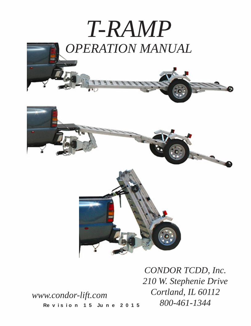
T-RAMPOPERATION MANUAL
2
Contents
1. IntroduCtIon ............................................................................................. 5
2. safety .................................................................................................... 6 2 . 1 S a f e t y Al e r t S y m b o l s An d S i g n a l Wo r d s . . . . . . . . . . . . . . . . . . . . . . . . . . . . . . . . . . . . . . . . . . . . . . . . . . . . . . . 6 2 . 2 M a j o r H a za r d s . . . . . . . . . . . . . . . . . . . . . . . . . . . . . . . . . . . . . . . . . . . . . . . . . . . . . . . . . . . . . . . . . . . . . . . . . . . . . . . . . . . . . . . . . . . . . . . . . . . 6 2.2.1 Improper sIzIng of traIler to tow VehICle ...................................................................... 6 2.2.2 drIVIng too fast .............................................................................................................. 6 2.2.3 adjust drIVIng when towIng t-ramp ................................................................................ 7 2.2.4 T - Ra m p not properly Coupled to hItCh ......................................................................... 7 2.2.5 proper use of safety Cables ......................................................................................... 8 2.2.7 matChIng traIler and hItCh ............................................................................................. 8 2.2.8 worn tIres, loose wheels and lug bolts ...................................................................... 8 2.2.9 Improper loadIng ............................................................................................................. 9 2.2.10 unsafe load dIstrIbutIon ............................................................................................... 9 2.2.11 shIftIng Cargo ............................................................................................................. 10 2.2.12 InapproprIate Cargo .................................................................................................... 10 2.2.13 Inoperable lIghts ......................................................................................................... 10 2.2.14 t-ramp modIfICatIons ................................................................................................... 10 2.2.15 traIler towIng guIde ................................................................................................... 10 2.2.16 safe traIler towIng guIdelInes ....................................................................................11 2.2.17 reportIng safety defeCts .............................................................................................11 2.2.18 safety warnIng label loCatIons ..................................................................................11
3. tIre safety InformatIon .......................................................................... 17 3 . 1 T r a i l e r T i r e In f o r m a t i o n . . . . . . . . . . . . . . . . . . . . . . . . . . . . . . . . . . . . . . . . . . . . . . . . . . . . . . . . . . . . . . . . . . . . . . . . . . . . . . . . . . . 1 7 3 . 2 S t e p s F o r D e t e r m i n i n g C o r r e c t L o a d L i m i t - T r a i l e r . . . . . . . . . . . . . . . . . . . . . . . . . . . . . . . . . . . . 1 8 3.2.1 traIlers 10,000 pounds gVwr or less ...................................................................... 18 3.2.2 traIlers oVer 10,000 pounds gVwr ........................................................................... 18 3 . 3 S t e p s F o r D e t e r m i n i n g C o r r e c t L o a d L i m i t - T o w V e h i c l e . . . . . . . . . . . . . . . . . . . . . . . . . . . 1 9 3 . 4 Gl o s s a r y O f T i r e T e r m i n o l o g y . . . . . . . . . . . . . . . . . . . . . . . . . . . . . . . . . . . . . . . . . . . . . . . . . . . . . . . . . . . . . . . . . . . . . . . . 1 9 3 . 5 T i r e S a f e t y - E v e r y t h i n g Ri d e s O n It . . . . . . . . . . . . . . . . . . . . . . . . . . . . . . . . . . . . . . . . . . . . . . . . . . . . . . . . . . . . . . 2 1 3.5.1 safety fIrst- basIC tIre maIntenanCe ............................................................................ 22 3.5.2 fIndIng your VehICle’s reCommended tIre pressure and load lImIts ............................. 22 3.5.3 understandIng tIre pressure and load lImIts ............................................................... 22 3.5.4 safety fIrst- basIC tIre maIntenanCe ............................................................................ 22 3.5.5 steps for maIntaInIng proper tIre pressure ................................................................. 22 3.5.6 tIre sIze ......................................................................................................................... 23 3.5.7 tIre tread ...................................................................................................................... 23 3.5.8 tIre balanCe and wheel alIgnment ............................................................................... 23 3.5.9 tIre repaIr ..................................................................................................................... 23 3.5.10 tIre fundamentals ........................................................................................................ 23 3.5.10.1 InformatIon on passenger VehICle tIres .............................................................. 23 3.5.10.2 U T Q GS In f o r m a t i o n . . . . . . . . . . . . . . . . . . . . . . . . . . . . . . . . . . . . . . . . . . . . . . . . . . . . . . . . . . . . . . . . . . . . . . . . . . . . . . . . . . . . . . . . . . . . . . . . . . . . . . . 2 4 3.5.10.3 Ad d i t i o n a l In f o r m a t i o n O n L i g h t T r u c k T i r e s . . . . . . . . . . . . . . . . . . . . . . . . . . . . . . . . . . . . . . . . . . . . . . . . . . . . . . . . . . . . . . 2 4 3.5.10.4 T i r e S a f e t y T i p s . . . . . . . . . . . . . . . . . . . . . . . . . . . . . . . . . . . . . . . . . . . . . . . . . . . . . . . . . . . . . . . . . . . . . . . . . . . . . . . . . . . . . . . . . . . . . . . . . . . . . . . . . . . . . . 2 5
Contents
3
4. CouplIng and unCouplIng ....................................................................... 26 4 . 1 T o w V e h i c l e An d H i t c h . . . . . . . . . . . . . . . . . . . . . . . . . . . . . . . . . . . . . . . . . . . . . . . . . . . . . . . . . . . . . . . . . . . . . . . . . . . . . . . . . . . . 2 6 4.1.1 t-ramp InformatIon ........................................................................................................ 26 4.1.2 tow VehICle .................................................................................................................... 26 4 . 2 T o n g u e We i g h t . . . . . . . . . . . . . . . . . . . . . . . . . . . . . . . . . . . . . . . . . . . . . . . . . . . . . . . . . . . . . . . . . . . . . . . . . . . . . . . . . . . . . . . . . . . . . . . . 2 6 4.2.1 CheCkIng tongue weIght ................................................................................................ 27 4 . 3 C o u p l e T o T o w V e h i c l e . . . . . . . . . . . . . . . . . . . . . . . . . . . . . . . . . . . . . . . . . . . . . . . . . . . . . . . . . . . . . . . . . . . . . . . . . . . . . . . . . . . 2 7 4.3.1 ConneCt safety Cables .................................................................................................. 30 4.3.2 CheCk lIghts .................................................................................................................. 30 4 . 4 Re m o v e T i r e / Ax l e As s e m b l i e s . . . . . . . . . . . . . . . . . . . . . . . . . . . . . . . . . . . . . . . . . . . . . . . . . . . . . . . . . . . . . . . . . . . . . . . 3 0 4 . 5 U n c o u p l e T - Ra m p . . . . . . . . . . . . . . . . . . . . . . . . . . . . . . . . . . . . . . . . . . . . . . . . . . . . . . . . . . . . . . . . . . . . . . . . . . . . . . . . . . . . . . . . . . . 3 1
5. t-ramp operatIons ................................................................................. 34 5 . 1 Ra m p An d T r a i l e r C o n f i g u r a t i o n s ....................................................... 34 5.1.1 folded on tow VehICle .................................................................................................. 34 5.1.2 ConfIgure t-ramp to ramp posItIon .............................................................................. 35 5.1.3 ConfIgure t-ramp to traIler posItIon ........................................................................... 39 5.1.4 rear ramp ...................................................................................................................... 41 5 . 2 T r a n s p o r t i n g T - Ra m p . . . . . . . . . . . . . . . . . . . . . . . . . . . . . . . . . . . . . . . . . . . . . . . . . . . . . . . . . . . . . . . . . . . . . . . . . . . . . . . . . . . . . . 4 2 5.2.1 ConfIgure t-ramp to folded posItIon ........................................................................... 42 5 . 3 Ad j u s t m e n t s . . . . . . . . . . . . . . . . . . . . . . . . . . . . . . . . . . . . . . . . . . . . . . . . . . . . . . . . . . . . . . . . . . . . . . . . . . . . . . . . . . . . . . . . . . . . . . . . . . . . 4 7 5.3.1 adjust ramp heIght........................................................................................................ 47 5.3.2 adjust traIler heIght .................................................................................................... 51
6. loadIng and unloadIng .......................................................................... 56 6 . 1 L o a d i n g . . . . . . . . . . . . . . . . . . . . . . . . . . . . . . . . . . . . . . . . . . . . . . . . . . . . . . . . . . . . . . . . . . . . . . . . . . . . . . . . . . . . . . . . . . . . . . . . . . . . . . . . . . . . 5 6 6 . 2 S e c u r i n g C a r g o . . . . . . . . . . . . . . . . . . . . . . . . . . . . . . . . . . . . . . . . . . . . . . . . . . . . . . . . . . . . . . . . . . . . . . . . . . . . . . . . . . . . . . . . . . . . . . . 5 6 6 . 3 U n l o a d . . . . . . . . . . . . . . . . . . . . . . . . . . . . . . . . . . . . . . . . . . . . . . . . . . . . . . . . . . . . . . . . . . . . . . . . . . . . . . . . . . . . . . . . . . . . . . . . . . . . . . . . . . . . . . 5 7
7. pre-tow CheCklIst ................................................................................. 58 7 . 1 P r e - T o w C h e c k l i s t . . . . . . . . . . . . . . . . . . . . . . . . . . . . . . . . . . . . . . . . . . . . . . . . . . . . . . . . . . . . . . . . . . . . . . . . . . . . . . . . . . . . . . . . . . . 5 8 7 . 2 M a k e Re g u l a r S t o p s . . . . . . . . . . . . . . . . . . . . . . . . . . . . . . . . . . . . . . . . . . . . . . . . . . . . . . . . . . . . . . . . . . . . . . . . . . . . . . . . . . . . . . . 5 8
8. break In ................................................................................................. 59 8 . 1 Re t i g h t e n L u g s At F i r s t 1 0 , 2 5 & 5 0 M i l e s . . . . . . . . . . . . . . . . . . . . . . . . . . . . . . . . . . . . . . . . . . . . . . . . . . . . . 5 9
9. InspeCtIon, serVICe and maIntenanCe ..................................................... 60 9 . 1 In s p e c t i o n , S e r v i c e An d M a i n t e n a n c e S u m m a r y C h a r t s . . . . . . . . . . . . . . . . . . . . . . . . . . . . . 6 0 9 . 2 In s p e c t i o n An d S e r v i c e In s t r u c t i o n s . . . . . . . . . . . . . . . . . . . . . . . . . . . . . . . . . . . . . . . . . . . . . . . . . . . . . . . . . . . . . 6 3 9.2.1 t-ramp struCture .......................................................................................................... 63 9.2.1.1 fasteners and frame members .............................................................................. 63 9.2.1.2 welds .................................................................................................................... 63 9.2.2 lIghts and sIgnals ......................................................................................................... 63 9.2.3 wheel rIms ..................................................................................................................... 63 9.2.4 tIres ............................................................................................................................... 63
Contents
4
9.2.5 wheel bearIngs .............................................................................................................. 64 9.2.6 lubrICatIon ..................................................................................................................... 65 9.2.7 lug bolts ....................................................................................................................... 66
10. eleCtrICal ............................................................................................ 67 1 0 . 1 C o n t r o l B o x . . . . . . . . . . . . . . . . . . . . . . . . . . . . . . . . . . . . . . . . . . . . . . . . . . . . . . . . . . . . . . . . . . . . . . . . . . . . . . . . . . . . . . . . . . . . . . . . . . . 6 7 1 0 . 2 P l u g In . . . . . . . . . . . . . . . . . . . . . . . . . . . . . . . . . . . . . . . . . . . . . . . . . . . . . . . . . . . . . . . . . . . . . . . . . . . . . . . . . . . . . . . . . . . . . . . . . . . . . . . . . . . . 6 7 1 0 . 3 Re p l a c e F u s e . . . . . . . . . . . . . . . . . . . . . . . . . . . . . . . . . . . . . . . . . . . . . . . . . . . . . . . . . . . . . . . . . . . . . . . . . . . . . . . . . . . . . . . . . . . . . . . . . 6 7 1 0 . 4 Wi r e l e s s Re m o t e B a t t e r y . . . . . . . . . . . . . . . . . . . . . . . . . . . . . . . . . . . . . . . . . . . . . . . . . . . . . . . . . . . . . . . . . . . . . . . . . . . . . . 6 8 10.4.1 battery replaCement ................................................................................................... 68 10.4.2 programmIng the remote ............................................................................................. 68
11. warranty ............................................................................................. 69
12. aCCessorIes .......................................................................................... 70
Contents
^ WARNINGT h i s O w n e r ’ s M a n u a l c o n t a i n s s a f e t yi n f o r m a t i o n a n d i n s t r u c t i o n s f o r y o u rt r a i l e r .
Y o u m u s t r e a d t h i s m a n u a l b e f o r e o p e r a t i n g , l o a d i n g o r t o w i n g y o u r t r a i l e r .
Y o u m u s t f o l l o w a l l s a f e t y p r e c a u t i o n s a n d i n s t r u c t i o n s .
5
1. IntroduCtIon
For your safety, read and understand this manual before operating your T-Ramp. If there are any questions about information in this manual, please consult your Condor dealer.
When calling about your T-Ramp, please have the VIN number available for the dealer. The VIN number is on the front left side of the T-Ramp.
For future reference, please write your VIN number in the space below:
___________________________________________
This manual covers the basic T-Ramp. You must read, understand and follow the instructions given by Condor, the tow vehicle and trailer hitch manufacturers. Keep all manuals provided with your T-Ramp in a safe place at all times.
Information provided in this manual was current as of the issue date. Condor reserves the right to make design changes without further notice or liability.
Introduction
6
2. safety
2.1 safety alert symbols and sIgnal words
An Owner’s Manual that provides general trailer information cannot cover all of the specific details necessary for the proper combination of every trailer, tow vehicle and hitch. You must read, understand and follow the instructions given by the tow vehicle and trailer hitch manufacturers, as well as the instructions in this manual.
Our T-Ramps are built with components produced by various manufacturers. Some of these items have separate instruction manuals. Where this manual indicates that you should read another manual, and you do not have that manual, contact your dealer for assistance.
The safety information in this manual is denoted by the safety alert symbol:
^This symbol means ATTENTION! BECOME ALERT! YOUR SAFETY IS INVOLVED!
The level of risk is indicated by the following signal words:
^ D ANGE RD ANGE R - In d i c a t e s a h a za r d o u s s i t u a t i o n , w h i c h , i f n o t a v o i d e d , WIL L r e s u l t i n d e a t h o r s e r i o u s i n j u r y .
^ WARNINGWARNING - In d i c a t e s a h a za r d o u s s i t u a t i o n , w h i c h , i f n o t a v o i d e d , c o u l d r e s u l t i n d e a t h o r s e r i o u s i n j u r y .
^ C AU T IO NC AU T IO N - In d i c a t e s a h a za r d o u s s i t u a t i o n , w h i c h , i f n o t a v o i d e d , c o u l d r e s u l t i n m i n o r o r m o d e r a t e i n j u r y .
NO T IC ENOTICE - Indicates a situation that could result in damage to the equipment or other property.
2.2 major hazards
Loss of control of the T-Ramp or trailer/tow vehicle combination can result in death or serious injury. The most common causes for loss of control of the trailer are:• Improper sizing the trailer for the tow vehicle, or
vice versa.• Excessive Speed: Driving too fast for the
conditions.• Improper braking and steering under sway
conditions• Overloading and/or improper weight distribution.• Not keeping lug bolts tight.• Failure to adjust driving behavior when towing
trailer.• Not maintaining proper tire pressure• Improper or mis-coupling of the trailer to the hitch.
2.2.1 Improper sIzIng of traIler to tow VehICle
Trailers that weigh too much for the tow vehicle can cause stability problems, which can lead to death or serious injury. The additional strain put on the engine and drive-train may lead to serious tow vehicle maintenance problems.
Do not exceed the maximum towing capacity of your tow vehicle. The towing capacity of your tow vehicle, in terms of maximum Gross Trailer Weight (GTW) and maximum Gross Combined Weight Rating (GCWR) can be found in the tow vehicle Owner’s Manual.
^ D ANGE RU s e o f a n u n d e r - r a t e d h i t c h , b a l l o r t o w v e h i c l e c a n r e s u l t i n l o s s o f c o n t r o l l e a d i n g t o d e a t h o r s e r i o u s i n j u r y .
M a k e c e r t a i n y o u r h i t c h a n d t o w v e h i c l e a r e r a t e d f o r y o u r t r a i l e r .
2.2.2 drIVIng too fast
With ideal road conditions, the maximum recommended speed for safely towing a trailer is 55 mph. Driving too fast can cause the trailer to sway, thus increasing
Safety
7
the possibility for loss of control. Also your tires may overheat, increasing the possibility of a blowout.
^ WARNINGD r i v i n g t o o f a s t f o r c o n d i t i o n s c a n r e s u l t i n l o s s o f c o n t r o l a n d c a u s e d e a t h o r s e r i o u s i n j u r y .
Ad j u s t s p e e d d o w n w h e n t o w i n g t r a i l e r .
2.2.3 adjust drIVIng when towIng t-ramp
When towing a T-Ramp, you will have decreased acceleration, increased stopping distance, and increased turning radius.
The T-Ramp will change the handling characteristics of the tow vehicle, making it more sensitive to steering inputs and more likely to be pushed around in windy conditions or when being passed by large vehicles. In addition, you will need a longer distance to pass, due to slower acceleration and increased length. With this in mind:• When encountering trailer sway, take your foot
off the accelerator, and steer as little as possible in order to stay on the road. Use small “trim-like” steering adjustments. Do not attempt to steer out of the sway; you’ll only make it worse.
• Check rearview mirrors frequently to observe T-Ramp and traffic.
• Be alert for slippery conditions. You are more likely to be affected by slippery road surfaces when driving a tow vehicle with a T-Ramp, than driving a tow vehicle without a T-Ramp.
• Anticipate the T-Ramp “swaying.” Swaying can be caused by excessive steering, wind gusts, roadway edges, or by the trailer reaction to the pressure wave created by passing trucks and busses.
• Use lower gear when driving down steep or long grades. Use the engine and transmission as a brake. Do not ride the brakes, as they can overheat and become ineffective.
2.2.4 T - Ra m p not properly Coupled to hItCh
It is critical that the T-Ramp be securely coupled to the hitch, and that the safety chains are correctly attached. Uncoupling may result in death or serious injury to you and to others.
^ WARNINGP r o p e r s e l e c t i o n a n d c o n d i t i o n o f t h e c o u p l e r a n d h i t c h a r e e s s e n t i a l t o s a f e l y t o w i n g a t r a i l e r .
A l o s s o f c o u p l i n g m a y r e s u l t i n d e a t h o r s e r i o u s i n j u r y .
B e s u r e h i t c h l o a d r a t i n g i s e q u a l t o o r g r e a t e r t h a n l o a d r a t i n g o f t h e c o u p l e r .
B e s u r e h i t c h c o m p o n e n t s a r e t i g h t b e f o r e c o u p l i n g t r a i l e r t o t o w v e h i c l e .
O b s e r v e h i t c h f o r w e a r , c o r r o s i o n a n d c r a c k s b e f o r e c o u p l i n g . Re p l a c e w o r n , c o r r o d e d o r c r a c k e d h i t c h c o m p o n e n t s b e f o r e c o u p l i n g t r a i l e r t o t o w v e h i c l e .
^ WARNINGAn i m p r o p e r l y c o u p l e d t r a i l e r c a n r e s u l t i n d e a t h o r s e r i o u s i n j u r y . D o n o t m o v e t h e t r a i l e r u n t i l :
• T - Ra m p i s s e c u r e d a n d l o c k e d t o h i t c h .• S a f e t y c a b l e s a r e s e c u r e d t o t o w
v e h i c l e .• T i r e s a n d w h e e l s a r e c h e c k e d .• T h e t r a i l e r l i g h t s a r e c o n n e c t e d a n d
c h e c k e d .• L o a d i s s e c u r e d t o t r a i l e r .
Safety

8
2.2.5 proper use of safety Cables
Safety cables are provided so that control of the trailer can be maintained if your trailer comes loose from the hitch.
^ WARNINGIm p r o p e r r i g g i n g o f t h e s a f e t y c a b l e s c a n r e s u l t i n l o s s o f c o n t r o l o f t h e t r a i l e r a n d t o w v e h i c l e , l e a d i n g t o d e a t h o r s e r i o u s i n j u r y , i f t h e t r a i l e r u n c o u p l e s f r o m t h e t o w v e h i c l e .
C r o s s c a b l e s u n d e r n e a t h h i t c h a n d c o u p l e r w i t h e n o u g h s l a c k t o p e r m i t t u r n i n g a n d t o h o l d t o n g u e u p , i f t h e t r a i l e r c o m e s l o o s e .
F a s t e n c a b l e s t o f r a m e o f t o w v e h i c l e .
D o n o t f a s t e n c a b l e s t o a n y p a r t o f t h e h i t c h u n l e s s t h e h i t c h h a s h o l e s o r l o o p s specificallyforthatpurpose.
2.2.7 matChIng traIler and hItCh
^ D ANGE RB e s u r e h i t c h a n d t o w v e h i c l e a r e r a t e d f o r t h e Gr o s s V e h i c l e We i g h t Ra t i n g ( GV WR) o f y o u r t r a i l e r .
U s e o f a h i t c h w i t h a l o a d r a t i n g l e s s t h a n t h e l o a d r a t i n g o f t h e t r a i l e r c a n r e s u l t i n l o s s o f c o n t r o l a n d m a y l e a d t o d e a t h o r s e r i o u s i n j u r y .
U s e o f a t o w v e h i c l e w i t h a t o w i n g c a p a c i t y l e s s t h a n t h e l o a d r a t i n g o f t h e t r a i l e r c a n r e s u l t i n l o s s o f c o n t r o l , a n d m a y l e a d t o d e a t h o r s e r i o u s i n j u r y .
2.2.8 worn tIres, loose wheels and lug bolts
Inspect T-Ramp tires before each tow. If a tire has a bald spot, bulge, cut, cracks, or is showing any cords, replace the tire before towing.
If a tire has uneven tread wear, take the T-Ramp to a trailer service center for diagnosis. Uneven tread wear can be caused by tire imbalance, axle misalignment or incorrect inflation.
Tires with too little tread will not provide adequate frictional forces on wet roadways and can result in loss of control, leading to death or serious injury.
Improper tire pressure causes increased tire wear and may reduce trailer stability, which can result in a tire blowout or possible loss of control. Check tire pressure before towing.
The proper tire pressure is listed on the Certification / VIN label, normally mounted on the front left side of the trailer, and should be checked when tires are cold. Allow 3 hours cool-down after driving as much as 1 mile at 40 mph before checking tire pressure.
^ WARNINGInflatetirestopressurestatedontheCertification/VINlabel.
Im p r o p e r t i r e p r e s s u r e m a y c a u s e u n s t a b l e t r a i l e r . B l o w o u t a n d l o s s o f c o n t r o l m a y o c c u r . D e a t h o r s e r i o u s i n j u r y c a n r e s u l t .
Inflatetirestocorrectpressurebeforet o w i n g t r a i l e r .
The tightness of the wheel bolts is very important in keeping the wheels properly seated to the hub. Before each tow, check to make sure they are tight.
^ WARNINGM e t a l c r e e p b e t w e e n t h e w h e e l r i m a n d w h e e l b o l t s m a y c a u s e r i m t o l o o s e n .
D e a t h o r i n j u r y c a n o c c u r i f w h e e l c o m e s o f f .
T i g h t e n l u g b o l t s b e f o r e e a c h t o w .
The proper tightness (torque) for wheel bolts and tightening sequence is listed in the Inspection, Service and Maintenance section of this manual. Use a torque wrench to tighten lug bolts and use the crisscross star pattern sequence. Improper tightening of the lug bolts voids the axle warranty.
Wheel bolts are also prone to loosen after first being assembled. When driving a new trailer (or after wheels have been remounted), check to make sure they are tight after the first 10, 25 and 50 miles of driving and before each tow thereafter.
Safety
9
Failure to perform this check can result in a wheel separating from the trailer and a crash, leading to death or serious injury.
^ WARNINGWh e e l b o l t s a r e p r o n e t o l o o s e n a f t e r b e i n g firstassembled.Deathorseriousinjuryc a n r e s u l t .
C h e c k w h e e l b o l t s f o r t i g h t n e s s o n a n e w t r a i l e r , a n d a f t e r r e - m o u n t i n g a w h e e l a t 1 0 , 2 5 a n d 5 0 m i l e s .
^ WARNINGIn a d e q u a t e w h e e l b o l t t o r q u e c a n c a u s e a w h e e l t o s e p a r a t e f r o m t h e t r a i l e r , l e a d i n g t o d e a t h o r s e r i o u s i n j u r y .
V e r i f y w h e e l b o l t s a r e t i g h t b e f o r e e a c h t o w .
2.2.9 Improper loadIng The total weight of the load you put on the T-Ramp, plus the empty weight of the T-Ramp itself, must not exceed the T-Ramp’s Gross Vehicle Weight Rating (GVWR).
If you do not know the empty weight of the T-Ramp plus the cargo weight, you must weigh the loaded T-Ramp at a commercial scale. In addition, you must distribute the load on the trailer such that the load on axle does not exceed the Gross Axle Weight Rating (GAWR).
If your T-Ramp is equipped with a Tire & Loading Information Placard, mounted next to the Certification / VIN label, the cargo capacity weight stated on that placard is only a close estimate. The GVWR and GAWR are listed on the Certification / VIN label normally located on the front left side of the T-Ramp.
^ WARNINGAn o v e r l o a d e d t r a i l e r c a n r e s u l t i n f a i l u r e o r l o s s o f c o n t r o l o f t h e t r a i l e r , l e a d i n g t o d e a t h o r s e r i o u s i n j u r y .
Ne v e r l o a d a t r a i l e r s o t h a t t h e w e i g h t o n a n y t i r e e x c e e d s i t s r a t i n g .
Ne v e r e x c e e d t h e t r a i l e r Gr o s s V e h i c l e We i g h t Ra t i n g ( GV WR) o r a x l e Gr o s s Ax l e We i g h t Ra t i n g ( GAWR) .
2.2.10 unsafe load dIstrIbutIon
Improper front / rear load distribution can lead to an unstable T-Ramp or poor tow vehicle handling. Poor trailer stability results from tongue weights that are too low, and poor tow vehicle stability results from tongue weights that are too high.
Refer to the “Loading And Unloading” section for more information.
The rule of thumb percentage of total weight of the trailer plus its cargo (Gross Trailer Weight, or “GTW”) that should appear on the tongue of the T-Ramp. For example, a trailer with a loaded weight of 2,000 pounds, should have 6-10% of 2,000 pounds (120-200 lbs.) on the hitch.
The numbers quoted are for example purposes only and should be tailored to the specific trailer.
After loading, be sure to check that the axle is not overloaded.
Uneven left / right load distribution can cause tire, wheel, axle or structural failure.
Be sure your trailer is evenly loaded left / right. Towing stability also depends on keeping the center of gravity as low as possible.
Safety
10
^ WARNINGIm p r o p e r t o n g u e w e i g h t ( l o a d d i s t r i b u t i o n ) c a n r e s u l t i n l o s s o f c o n t r o l o f t h e T - Ra m p , l e a d i n g t o d e a t h o r s e r i o u s i n j u r y .
M a k e c e r t a i n t h a t t o n g u e w e i g h t i s w i t h i n t h e a l l o w a b l e r a n g e .
B e s u r e t o :•Distributetheloadevenly,rightandleft.•Keepthecenterofgravitylow.•Distributetheloadfront-to-reartoprovide
p r o p e r t o n g u e w e i g h t .
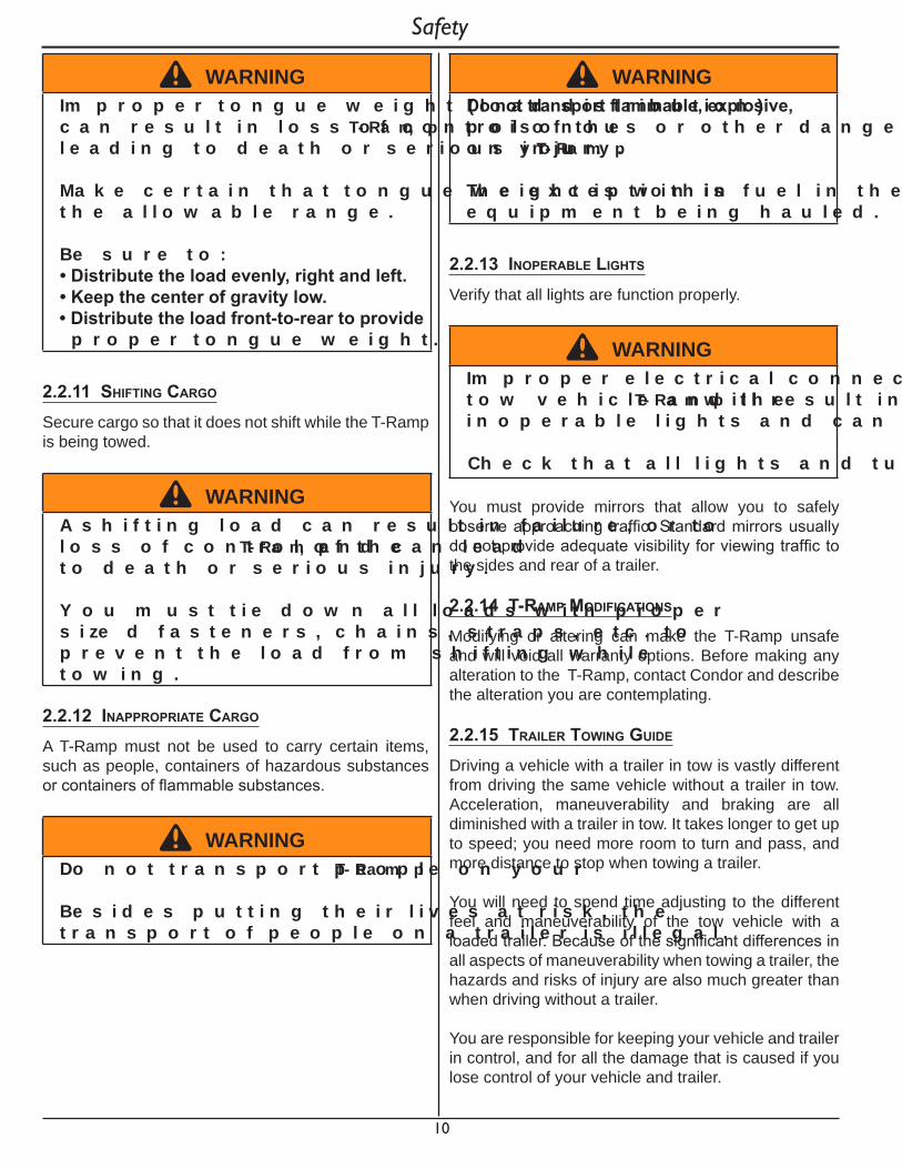
2.2.11 shIftIng Cargo
Secure cargo so that it does not shift while the T-Ramp is being towed.
^ WARNINGA s h i f t i n g l o a d c a n r e s u l t i n f a i l u r e , o r t o l o s s o f c o n t r o l o f t h e T - Ra m p , a n d c a n l e a d t o d e a t h o r s e r i o u s i n j u r y .
Y o u m u s t t i e d o w n a l l l o a d s w i t h p r o p e r s i ze d f a s t e n e r s , c h a i n s , s t r a p s , e t c . t o p r e v e n t t h e l o a d f r o m s h i f t i n g w h i l e t o w i n g .
2.2.12 InapproprIate Cargo A T-Ramp must not be used to carry certain items, such as people, containers of hazardous substances or containers of flammable substances.
^ WARNINGD o n o t t r a n s p o r t p e o p l e o n y o u r T - Ra m p .
B e s i d e s p u t t i n g t h e i r l i v e s a t r i s k , t h e t r a n s p o r t o f p e o p l e o n a t r a i l e r i s i l l e g a l .
^ WARNINGDonottransportflammable,explosive,p o i s o n o u s o r o t h e r d a n g e r o u s m a t e r i a l s o n y o u r T - Ra m p .
T h e e x c e p t i o n i s f u e l i n t h e t a n k o f e q u i p m e n t b e i n g h a u l e d .
2.2.13 Inoperable lIghts
Verify that all lights are function properly.
^ WARNINGIm p r o p e r e l e c t r i c a l c o n n e c t i o n b e t w e e n t h e t o w v e h i c l e a n d t h e T - Ra m p w i l l r e s u l t i n i n o p e r a b l e l i g h t s a n d c a n l e a d t o c o l l i s i o n .
C h e c k t h a t a l l l i g h t s a n d t u r n s i g n a l s w o r k .
You must provide mirrors that allow you to safely observe approaching traffic. Standard mirrors usually do not provide adequate visibility for viewing traffic to the sides and rear of a trailer.
2.2.14 t-ramp modIfICatIons
Modifying or altering can make the T-Ramp unsafe and will void all warranty options. Before making any alteration to the T-Ramp, contact Condor and describe the alteration you are contemplating.
2.2.15 traIler towIng guIde
Driving a vehicle with a trailer in tow is vastly different from driving the same vehicle without a trailer in tow. Acceleration, maneuverability and braking are all diminished with a trailer in tow. It takes longer to get up to speed; you need more room to turn and pass, and more distance to stop when towing a trailer.
You will need to spend time adjusting to the different feel and maneuverability of the tow vehicle with a loaded trailer. Because of the significant differences in all aspects of maneuverability when towing a trailer, the hazards and risks of injury are also much greater than when driving without a trailer.
You are responsible for keeping your vehicle and trailer in control, and for all the damage that is caused if you lose control of your vehicle and trailer.
Safety
11
Find an open area with little or no traffic for your first practice. Before you start towing the trailer, you must follow all of the instructions for inspection, testing, loading and coupling. Also, before you start towing, adjust the mirrors so you can see the trailer as well as the area to the rear of it.
Drive slowly at first, 5 mph or so, and turn the wheel to get the feel of how the tow vehicle and trailer combination responds. Next, make some right and left hand turns. Watch in your side mirrors to see how the trailer follows the tow vehicle. Turning with a trailer attached requires more room.
Stop the rig a few times from speeds no greater than 10 mph.
It will take practice to learn how to back up a tow vehicle with a trailer attached. Take it slow. Before backing up, get out of the tow vehicle and look behind the trailer to make sure that there are no obstacles.
2.2.16 safe traIler towIng guIdelInes
Before towing or hauling, check coupling, safety cables, tires and lights.
Check wheel bolts for tightness. Recheck load tie downs to make sure load will not shift during towing.
Check coupler tightness after 50 miles.
Allow plenty of stopping space for your trailer and tow vehicle.
Use lower gears for climbing and descending grades.
Do not ride brakes while descending grades; they may get so hot that they stop working. Then you will potentially have a runaway tow vehicle and trailer.
Make regular stops, about once each hour. Confirm that:• The coupler is secure to the hitch and is locked.• Electrical cable is connected.• There is appropriate slack in safety chains.• The tires are not visibly low on pressure.• The cargo is secure and in good condition.
Slow down for bumps in the road.
Do not brake while in a curve unless absolutely necessary. Instead, slow down before you enter the curve.
Do not drive so fast that the trailer begins to sway due to speed. Generally never drive faster than 55 m.p.h.
Allow plenty of room for passing. A rule of thumb is that the passing distance with a trailer is 4 times the passing distance without a trailer.
2.2.17 reportIng safety defeCts
If you believe that your vehicle has a defect that could cause a crash or could cause injury or death, you should immediately inform the National Highway Traffic Safety Administration (NHTSA) in addition to notifying Condor TCDD, Inc.
If NHTSA receives similar complaints, it may open an investigation, and if it finds that a safety defect exists in a group of vehicles, it may order a recall and remedy campaign. However, NHTSA cannot become involved in individual problems between you, your dealer, or Condor TCDD, Inc.
To contact NHTSA, you may call the Vehicle Safety Hotline toll-free at 1-888-327-4236 (TTY: 1-800-424-9153); or go to http://www.safercar.gov; or write to:
Administrator, NHTSA, 1200 New Jersey SE, Washington, DC 20590.
You can also obtain other information about motor vehicle safety from http://www.safercar.gov.
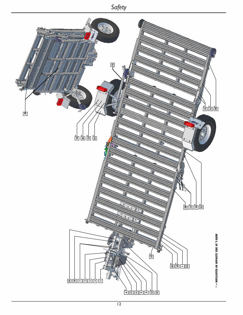
2.2.18 safety warnIng label loCatIons
^ WARNINGT o p r o t e c t y o u a n d o t h e r s a g a i n s t d e a t h o r s e r i o u s i n j u r y , a l l a p p l i c a b l e l a b e l s s h o w n m u s t b e o n t h e t r a i l e r a n d m u s t b e l e g i b l e .
If a n y o f t h e s e l a b e l s a r e m i s s i n g o r c a n n o t b e r e a d , c o n t a c t y o u r d e a l e r f o r r e p l a c e m e n t l a b e l s .
Safety
12
Safety
13
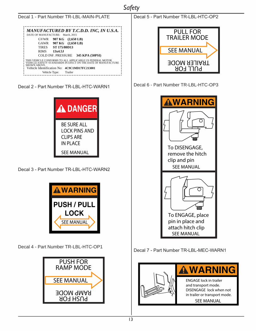
SafetyDecal 1 - Part Number TR-LBL-MAIN-PLATE
GVWR 907 KG (2,650 LB) GAWR 907 KG (2,650 LB)TIRES ST 175/80D13 RIMS 13x4.5JCOLD INF. PRESSURE 345 KPA (50PSI)
THIS VEHICLE CONFORMS TO ALL APPLICABLE US FEDERAL MOTOR VEHICLE-SAFETY STANDARDS IN EFECT ON THE DATE OF MANUFACTURE SHOWN ABOVE.Vehicle Identification No: 4C9C1MD17FC213001
DATE OF MANUFACTURE: March, 2015 MANUFACTURED BY T.C.D.D. INC, IN U.S.A.
Vehicle Type: Trailer
Decal 2 - Part Number TR-LBL-HTC-WARN1
DANGERBE SURE ALLLOCK PINS ANDCLIPS AREIN PLACE
SEE MANUAL
Decal 3 - Part Number TR-LBL-HTC-WARN2
WARNING
PUSH / PULLLOCK
SEE MANUAL
Decal 4 - Part Number TR-LBL-HTC-OP1
SEE MANUAL
PUSH FORRAMP MODE
PUSH FORRAMP MODE
Decal 5 - Part Number TR-LBL-HTC-OP2
SEE MANUAL
PULL FORTRAILER MODE
PULL FORTRAILER MODE
Decal 6 - Part Number TR-LBL-HTC-OP3
To DISENGAGE,remove the hitchclip and pin
SEE MANUAL
To ENGAGE, placepin in place andattach hitch clip
SEE MANUAL
WARNING
Decal 7 - Part Number TR-LBL-MEC-WARN1
WARNINGENGAGE lock in trailerand transport mode.DISENGAGE lock when notin trailer or transport mode.
SEE MANUAL

14
SafetyDecal 8 - Part Number TR-LBL-MEC-WARN
WARNINGUse ActuatorExtend/Retract toadjust theposition toEngage/Disengage locksSEE MANUAL
Decal 9 - Part Number TR-LBL-MEC-WARN3
ENGAGE lock inTrailer andTransport mode
DISENGAGE lockwhen not in Trailoror Transport mode
SEE MANUAL
WARNING
SEE MANUAL
Decal 10 - Part Number TR-LBL-MEC-WARN4
WARNINGENGAGElock inTrailer andTransportmode
DISENGAGElock whennot in Traileror Transportmode
Decal 11 - Part Number TR-LBL-NO-STEP1
NOT A STEPCAUTION
Decal 12 - Part Number TR-LBL-NO-STEP2
NOT A STEPCAUTION
Decal 13 - Part Number TR-LBL-PINCH1
Pinch pointKeep handsclear during
operation
WARNING
Decal 14 - Part Number TR-LBL-PINCH2
WARNINGPinch point.
Keep hands clear during operation.
Decal 15 - Part Number TR-LBL-PINCH3
WARNINGPinch point.
Keep hands clear during operation.
15
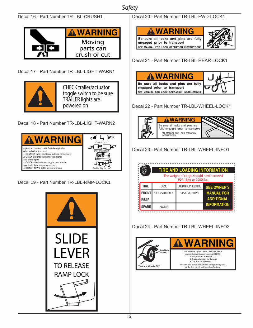
SafetyDecal 16 - Part Number TR-LBL-CRUSH1
WARNINGMoving
parts cancrush or cut
Decal 17 - Part Number TR-LBL-LIGHT-WARN1
CHECK trailer/actuator toggle switch to be sureTRAILER lights are powered on
Decal 18 - Part Number TR-LBL-LIGHT-WARN2
WARNING Connected
Disconnected
Trailer lights on
Lights can prevent trailer from being hit byother vehicles. You must:1. CONNECT trailer and tow electrical connectors.2. CHECK all lights: tail lights, turn signal, and brake lights.3. CHECK trailer/actuator toggle switch to be sure trailer lights are powered on.4. DO NOT TOW if lights are not working.
Decal 19 - Part Number TR-LBL-RMP-LOCK1
SLIDELEVERTO RELEASERAMP LOCK
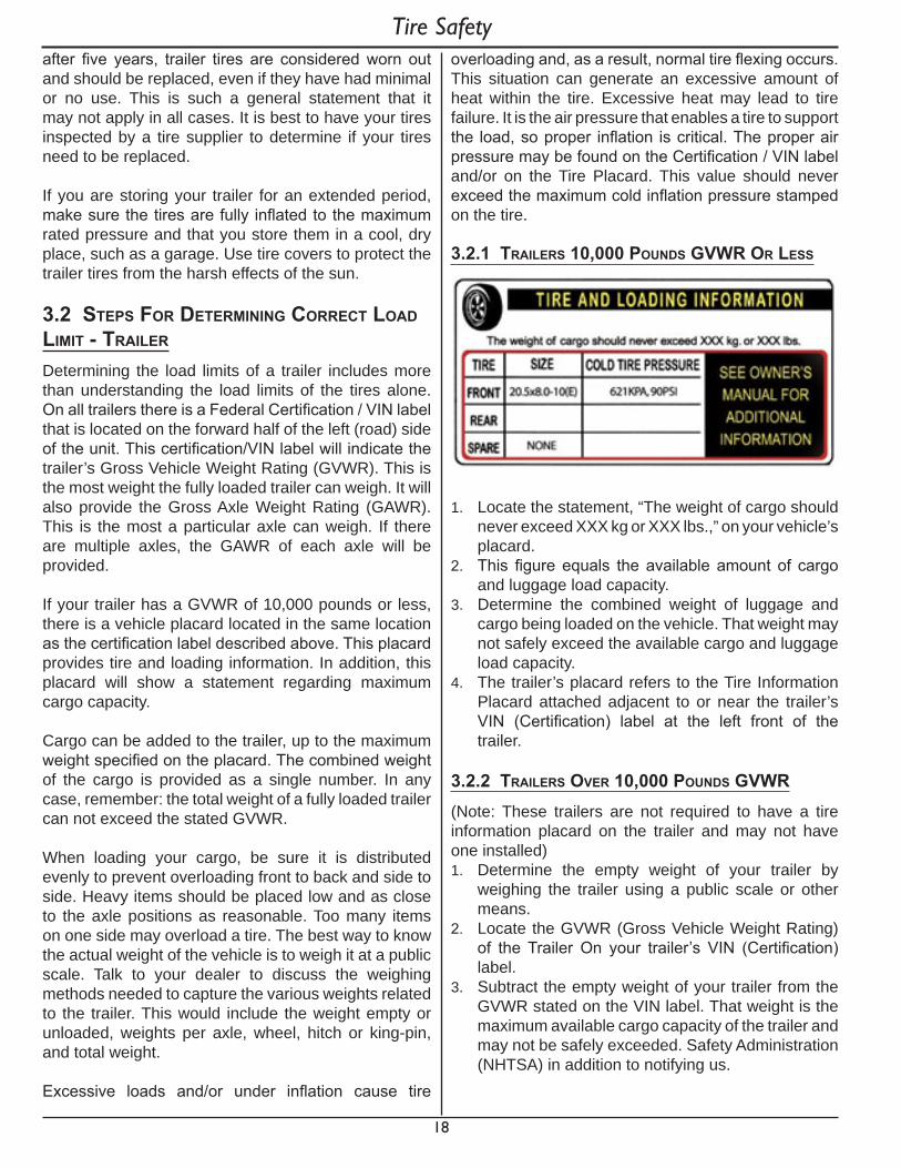
Decal 20 - Part Number TR-LBL-FWD-LOCK1
WARNINGBe sure all locks and pins are fullyengaged prior to transportSEE MANUAL FOR LOCK OPERATION INSTRUCTIONS
Decal 21 - Part Number TR-LBL-REAR-LOCK1
WARNINGBe sure all locks and pins are fullyengaged prior to transportSEE MANUAL FOR LOCK OPERATION INSTRUCTIONS
Decal 22 - Part Number TR-LBL-WHEEL-LOCK1
Be sure all locks and pins are fully engaged prior to transport
SEE MANUAL FOR LOCK OPERATIONINSTRUCTIONS
WARNING
Decal 23 - Part Number TR-LBL-WHEEL-INFO1
ST 175/80D13 345KPA, 50PSI
NONE
The weight of cargo should never exceed907.18kg or 2000 lbs.
Decal 24 - Part Number TR-LBL-WHEEL-INFO2
Tires and Wheels OK?
Lug NutsTIGHT?
WARNINGTire, wheel or lugnut failure can cause loss of
control. Before towing, you must CHECK:1. Tire pressure and tread2. Tires and wheels for damage3. Lug nuts for tightness
For new and remounted wheels, re-tighten lug nutsat the �rst 10, 25, and 50 miles of driving

16
SafetyDecal 25 - Part Number TR-LBL-KICK-WARN1
REMOVE BEFORE TRANSPORT
R E M O V E B E F O R E T R A N S P O R T
Decal 26 - Part Number TR-LBL-TOW-WARN1
WARNINGCheck the following points EACH TIME before towing trailer.•MAKE SURE all parts, bolts and nuts are tight.•Secure load trailer-check tilt and tie down mechanisms-use extra rope as a safety measure.•Check tire air pressure when tire is cold.•Repack wheel bearing once a year, preferably in the fall before storing trailer.•MAKE SURE you are not exceeding trailer capacity.•Cross safety cables under tongue and secure to towing vehicle. If equipped, hook up break-away brake cable with slack to permit cornering.•MAKE SURE the trailer electrical connector is properly connected and all lights are operating.•Check brake operation.•MAKE SURE jack is raised to its highest position.•MAKE SURE all gates and latches are secured.
Decal 27 - Part Number TR-LBL-CABLE-WARN1
ALWAYS use safety cables. Cables hold trailer if connection fails. You must:1. CROSS cables underneath coupler.2. ALLOW slack for trailer to turn.3. ATTACH cable hooks secure to tow vehicle frame.
ATTACH HOOKS TO TOW VEHICLE FRAME
CROSS CABLES
WARNING
Decal 28 - Part Number TR-LBL-RMP-REFL-AMBAmber Reflective Tape
Decal 29 - Part Number TR-LBL-RMP-REFL-REDRed Reflective Tape
Decal 30 - Part Number TR-LBL-FOLD-WARN
SEE MANUAL FOR LOCK OPERATION INSTRUCTIONS
WARNINGBe Sure All Locks are fully engaged before attempting to move T-Ramp

17
3. tIre safety InformatIon
This portion of the User’s Manual contains tire safety information as required by 49 CFR 575.6.
Section 3.1 contains “Trailer Tire Information”.
Section 3.2 contains “Steps for Determining Correct Load Limit - Trailer”.
Section 3.3 contains “Steps for Determining Correct Load Limit – Tow Vehicle”.
Section 3.4 contains a Glossary of Tire Terminology, including “cold inflation pressure”, “maximum inflation pressure”, “recommended inflation pressure”, and other non-technical terms.
Section 3.5 contains information from the NHTSA brochure entitled “Tire Safety – Everything Rides On It”.
This brochure, as well as preceding subsections, describes the following items;• Tire labeling, including a description and explanation
of each marking on the tires, and information about the DOT Tire Identification Number (TIN).
• Recommended tire inflation pressure, including a description and explanation of:
A. Cold inflation pressure.B. Vehicle Placard and location on the vehicle.C. Adverse safety consequences of under inflation
(including tire failure).D. Measuring and adjusting air pressure for proper
inflation.• Tire Care, including maintenance and safety
practices.• Vehicle load limits, including a description and
explanation of the following items:A. Locating and understanding the load limit
information, total load capacity, and cargo capacity.
B. Calculating total and cargo capacities with varying seating configurations including quantitative examples showing / illustrating how the vehicles cargo and luggage capacity decreases as combined number and size of occupants’ increases. This item is also discussed in Section 3.
C. Determining compatibility of tire and vehicle load capabilities.
D. Adverse safety consequences of overloading on handling and stopping on tires.
3.1 traIler tIre InformatIon
Trailer tires may be worn out even though they still have plenty of tread left. This is because trailer tires have to carry a lot of weight all the time, even when not in use.
It is actually better for the tire to be rolling down the road than to be idle. During use, the tire releases lubricants that are beneficial to tire life. Using the trailer tires often also helps prevent flat spots from developing.
The main cause of tire failure is improper inflation. Check the cold tire inflation pressures at least once a week for proper inflation levels. “Cold” means that the tires are at the same temperature as the surrounding air, such as when the vehicle has been parked overnight. Wheel and tire manufacturers recommend adjusting the air pressure to the trailer manufacturer’s recommended cold inflation pressure, in pounds per square inch (PSI) stated on the vehicle’s Federal Certification Label or Tire Placard when the trailer is loaded to its gross vehicle weight rating (GVWR).
If the tires are inflated to less than the recommended inflation level or the GVWR of the trailer is exceeded, the load carrying capacity of the tire could be dramatically affected. If the tires are inflated more than the recommended inflation level, handling characteristics of the tow vehicle/trailer combination could be affected. Refer to the owner’s manual or talk to your dealer or vehicle manufacturer if you have any questions regarding proper inflation practices.
Tires can lose air over a period of time. In fact, tires can lose 1 to 3 PSI per month. This is because molecules of air, under pressure, weave their way from the inside of the tire, through the rubber, to the outside. A drop in tire pressure could cause the tire to become overloaded, leading to excessive heat build up. If a trailer tire is under-inflated, even for a short period of time, the tire could suffer internal damage.
High speed towing in hot conditions degrades trailer tires significantly. As heat builds up during driving, the tire’s internal structure starts to breakdown, compromising the strength of the tire. It is recommended to drive at moderate speeds.
Statistics indicate the average life of a trailer tire is about five years under normal use and maintenance conditions. After three years, replacing the trailer tires with new ones should be considered, even if the tires have adequate tread depth. Some experts claim that
Tire Safety
18
overloading and, as a result, normal tire flexing occurs. This situation can generate an excessive amount of heat within the tire. Excessive heat may lead to tire failure. It is the air pressure that enables a tire to support the load, so proper inflation is critical. The proper air pressure may be found on the Certification / VIN label and/or on the Tire Placard. This value should never exceed the maximum cold inflation pressure stamped on the tire.
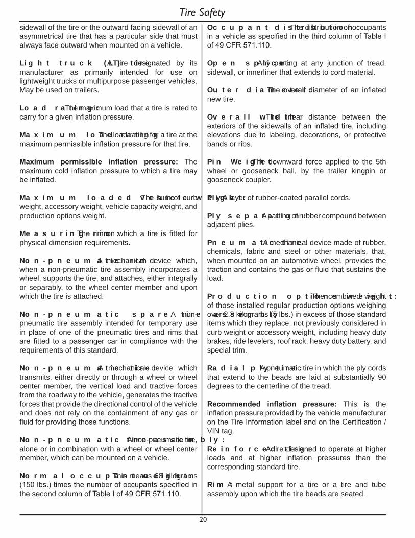
3.2.1 traIlers 10,000 pounds gVwr or less
1. Locate the statement, “The weight of cargo should never exceed XXX kg or XXX lbs.,” on your vehicle’s placard.
2. This figure equals the available amount of cargo and luggage load capacity.
3. Determine the combined weight of luggage and cargo being loaded on the vehicle. That weight may not safely exceed the available cargo and luggage load capacity.
4. The trailer’s placard refers to the Tire Information Placard attached adjacent to or near the trailer’s VIN (Certification) label at the left front of the trailer.
3.2.2 traIlers oVer 10,000 pounds gVwr (Note: These trailers are not required to have a tire information placard on the trailer and may not have one installed)1. Determine the empty weight of your trailer by
weighing the trailer using a public scale or other means.
2. Locate the GVWR (Gross Vehicle Weight Rating) of the Trailer On your trailer’s VIN (Certification) label.
3. Subtract the empty weight of your trailer from the GVWR stated on the VIN label. That weight is the maximum available cargo capacity of the trailer and may not be safely exceeded. Safety Administration (NHTSA) in addition to notifying us.
after five years, trailer tires are considered worn out and should be replaced, even if they have had minimal or no use. This is such a general statement that it may not apply in all cases. It is best to have your tires inspected by a tire supplier to determine if your tires need to be replaced.
If you are storing your trailer for an extended period, make sure the tires are fully inflated to the maximum rated pressure and that you store them in a cool, dry place, such as a garage. Use tire covers to protect the trailer tires from the harsh effects of the sun.
3.2 steps for determInIng CorreCt load lImIt - traIler
Determining the load limits of a trailer includes more than understanding the load limits of the tires alone. On all trailers there is a Federal Certification / VIN label that is located on the forward half of the left (road) side of the unit. This certification/VIN label will indicate the trailer’s Gross Vehicle Weight Rating (GVWR). This is the most weight the fully loaded trailer can weigh. It will also provide the Gross Axle Weight Rating (GAWR). This is the most a particular axle can weigh. If there are multiple axles, the GAWR of each axle will be provided.
If your trailer has a GVWR of 10,000 pounds or less, there is a vehicle placard located in the same location as the certification label described above. This placard provides tire and loading information. In addition, this placard will show a statement regarding maximum cargo capacity.
Cargo can be added to the trailer, up to the maximum weight specified on the placard. The combined weight of the cargo is provided as a single number. In any case, remember: the total weight of a fully loaded trailer can not exceed the stated GVWR.
When loading your cargo, be sure it is distributed evenly to prevent overloading front to back and side to side. Heavy items should be placed low and as close to the axle positions as reasonable. Too many items on one side may overload a tire. The best way to know the actual weight of the vehicle is to weigh it at a public scale. Talk to your dealer to discuss the weighing methods needed to capture the various weights related to the trailer. This would include the weight empty or unloaded, weights per axle, wheel, hitch or king-pin, and total weight.
Excessive loads and/or under inflation cause tire
Tire Safety

19
3.3 steps for determInIng CorreCt load lImIt - tow VehICle
1. Locate the statement, “The combined weight of occupants and cargo should never exceed XXX lbs.,” on your vehicle’s placard.
2. Determine the combined weight of the driver and passengers who will be riding in your vehicle.
3. Subtract the combined weight of the driver and passengers from XXX kilograms or XXX pounds.
4. The resulting figure equals the available amount of cargo and luggage capacity. For example, if the “XXX” amount equals 1400 lbs. and there will be five 150 lb. passengers in your vehicle, the amount of available cargo and luggage capacity is 650 lbs. (1400-750 (5 x 150) = 650 lbs.).
5. Determine the combined weight of luggage and cargo being loaded on the vehicle. That weight may not safely exceed the available cargo and luggage capacity calculated in previous step.
6. If your vehicle will be towing a trailer, load from your trailer will be transferred to your vehicle. Consult the tow vehicle’s manual to determine how this weight transfer reduces the available cargo and luggage capacity of your vehicle.
3.4 glossary of tIre termInology
Ac c e s s o r y w e i g h t : The combined weight (in excess of those standard items which may be replaced) of automatic transmission, power steering, power brakes, power windows, power seats, radio and heater, to the extent that these items are available as factory-installed equipment (whether installed or not).
B e a d : The part of the tire that is made of steel wires, wrapped or reinforced by ply cords and that is shaped to fit the rim.
B e a d s e p a r a t i o n : This is the breakdown of the bond between components in the bead.
B i a s p l y t i r e : A pneumatic tire in which the ply cords that extend to the beads are laid at alternate angles substantially less than 90 degrees to the centerline of the tread.
C a r c a s s : The tire structure, except tread and sidewall rubber which, when inflated, bears the load.
C h u n k i n g : The breaking away of pieces of the tread or sidewall.
Cold inflation pressure: The pressure in the tire before you drive.
C o r d : The strands forming the plies in the tire.
C o r d s e p a r a t i o n : The parting of cords from adjacent rubber compounds.
C r a c k i n g Any parting within the tread, sidewall, or inner liner of the tire extending to cord material.
C T : A pneumatic tire with an inverted flange tire and rim system in which the rim is designed with rim flanges pointed radially inward and the tire is designed to fit on the underside of the rim in a manner that encloses the rim flanges inside the air cavity of the tire.
C u r b w e i g h t : The weight of a motor vehicle with standard equipment including the maximum capacity of fuel, oil, and coolant, and, if so equipped, air conditioning and additional weight optional engine.
E x t r a l o a d t i r e : A tire designed to operate at higher loads and at higher inflation pressures than the corresponding standard tire.
Gr o o v e : The space between two adjacent tread ribs.
Gr o s s Ax l e We i g h t Ra t i n g : The maximum weight that any axle can support, as published on the Certification / VIN label on the front left side of the trailer. Actual weight determined by weighing each axle on a public scale, with the trailer attached to the towing vehicle.
Gr o s s V e h i c l e We i g h t Ra t i n g : The maximum weight of the fully loaded trailer, as published on the Certification / VIN label. Actual weight determined by weighing Trailer On a public scale, without being attached to the towing vehicle.
H i t c h We i g h t : The downward force exerted on the hitch ball by the trailer coupler.
In n e r l i n e r : The layer(s) forming the inside surface of a tubeless tire that contains the inflating medium within the tire.
In n e r l i n e r s e p a r a t i o n : The parting of the innerliner from cord material in the carcass.
In t e n d e d o u t b o a r d s i d e w a l l : The sidewall that contains a white-wall, bears white lettering or bears manufacturer, brand, and/or model name molding that is higher or deeper than the same molding on the other
Tire Safety
20
sidewall of the tire or the outward facing sidewall of an asymmetrical tire that has a particular side that must always face outward when mounted on a vehicle.
L i g h t t r u c k ( L T ) t i r e : A tire designated by its manufacturer as primarily intended for use on lightweight trucks or multipurpose passenger vehicles. May be used on trailers.
L o a d r a t i n g : The maximum load that a tire is rated to carry for a given inflation pressure.
M a x i m u m l o a d r a t i n g : The load rating for a tire at the maximum permissible inflation pressure for that tire.
Maximum permissible inflation pressure: The maximum cold inflation pressure to which a tire may be inflated.
M a x i m u m l o a d e d v e h i c l e w e i g h t : The sum of curb weight, accessory weight, vehicle capacity weight, and production options weight.
M e a s u r i n g r i m : The rim on which a tire is fitted for physical dimension requirements.
No n - p n e u m a t i c r i m : A mechanical device which, when a non-pneumatic tire assembly incorporates a wheel, supports the tire, and attaches, either integrally or separably, to the wheel center member and upon which the tire is attached.
No n - p n e u m a t i c s p a r e t i r e a s s e m b l y : A non-pneumatic tire assembly intended for temporary use in place of one of the pneumatic tires and rims that are fitted to a passenger car in compliance with the requirements of this standard.
No n - p n e u m a t i c t i r e : A mechanical device which transmits, either directly or through a wheel or wheel center member, the vertical load and tractive forces from the roadway to the vehicle, generates the tractive forces that provide the directional control of the vehicle and does not rely on the containment of any gas or fluid for providing those functions.
No n - p n e u m a t i c t i r e a s s e m b l y : A non-pneumatic tire, alone or in combination with a wheel or wheel center member, which can be mounted on a vehicle.
No r m a l o c c u p a n t w e i g h t : This means 68 kilograms (150 lbs.) times the number of occupants specified in the second column of Table I of 49 CFR 571.110.
O c c u p a n t d i s t r i b u t i o n : The distribution of occupants in a vehicle as specified in the third column of Table I of 49 CFR 571.110.
O p e n s p l i c e : Any parting at any junction of tread, sidewall, or innerliner that extends to cord material.
O u t e r d i a m e t e r : The overall diameter of an inflated new tire.
O v e r a l l w i d t h : The linear distance between the exteriors of the sidewalls of an inflated tire, including elevations due to labeling, decorations, or protective bands or ribs.
P i n We i g h t : The downward force applied to the 5th wheel or gooseneck ball, by the trailer kingpin or gooseneck coupler.
P l y : A layer of rubber-coated parallel cords.
P l y s e p a r a t i o n : A parting of rubber compound between adjacent plies.
P n e u m a t i c t i r e : A mechanical device made of rubber, chemicals, fabric and steel or other materials, that, when mounted on an automotive wheel, provides the traction and contains the gas or fluid that sustains the load.
P r o d u c t i o n o p t i o n s w e i g h t : The combined weight of those installed regular production options weighing over 2.3 kilograms (5 lbs.) in excess of those standard items which they replace, not previously considered in curb weight or accessory weight, including heavy duty brakes, ride levelers, roof rack, heavy duty battery, and special trim.
Ra d i a l p l y t i r e : A pneumatic tire in which the ply cords that extend to the beads are laid at substantially 90 degrees to the centerline of the tread.
Recommended inflation pressure: This is the inflation pressure provided by the vehicle manufacturer on the Tire Information label and on the Certification / VIN tag.
Re i n f o r c e d t i r e : A tire designed to operate at higher loads and at higher inflation pressures than the corresponding standard tire.
Ri m : A metal support for a tire or a tire and tube assembly upon which the tire beads are seated.
Tire Safety
21
axle its share of the curb weight, accessory weight, and normal occupant weight (distributed in accordance with Table I of CRF 49 571.110) and dividing by 2.
We a t h e r s i d e : The surface area of the rim not covered by the inflated tire.
Wh e e l c e n t e r m e m b e r : In the case of a non-pneumatic tire assembly incorporating a wheel, a mechanical device which attaches, either integrally or separably, to the non-pneumatic rim and provides the connection between the nonpneumatic rim and the vehicle; or, in the case of a non-pneumatic tire assembly not incorporating a wheel, a mechanical device which attaches, either integrally or separably, to the non-pneumatic tire and provides the connection between tire and the vehicle.
Wheel-holdingfixture: The fixture used to hold the wheel and tire assembly securely during testing.
3.5 tIre safety - eVerythIng rIdes on ItThe National Traffic Safety Administration (NHTSA) has published a brochure (DOT HS 809 361) that discusses all aspects of Tire Safety, as required by CFR 575.6. This brochure is reproduced in part below. It can be obtained and downloaded from NHTSA, free of charge, from the following web site:
http://www.nhtsa.dot.gov/cars/rules/TireSafety/ridesonit/tires_index.html
Studies of tire safety show that maintaining proper tire pressure, observing tire and vehicle load limits (not carrying more weight in your vehicle than your tires or vehicle can safely handle), avoiding road hazards, and inspecting tires for cuts, slashes, and other irregularities are the most important things you can do to avoid tire failure, such as tread separation or blowout and flat tires. These actions, along with other care and maintenance activities, can also:
• Improve vehicle handling• Help protect you and others from avoidable
breakdowns and accidents• Improve fuel economy• Increase the life of your tires.
This booklet presents a comprehensive overview of tire safety, including information on the following topics:
• Basic tire maintenance• Uniform Tire Quality Grading System
Ri m d i a m e t e r : This means the nominal diameter of the bead seat.
Ri m s i ze d e s i g n a t i o n : This means the rim diameter and width.
Ri m t y p e d e s i g n a t i o n : This means the industry of manufacturer’s designation for a rim by style or code.
Ri m w i d t h : This means the nominal distance between rim flanges.
S e c t i o n w i d t h : The linear distance between the exteriors of the sidewalls of an inflated tire, excluding elevations due to labeling, decoration, or protective bands.
S i d e w a l l: That portion of a tire between the tread and bead.
S i d e w a l l s e p a r a t i o n : The parting of the rubber compound from the cord material in the sidewall.
S p e c i a l T r a i l e r ( S T ) t i r e : The “ST” is an indication the tire is for trailer use only.
T e s t r i m : The rim on which a tire is fitted for testing, and may be any rim listed as appropriate for use with that tire.
T r e a d : That portion of a tire that comes into contact with the road.
T r e a d r i b : A tread section running circumferentially around a tire.
T r e a d s e p a r a t i o n : Pulling away of the tread from the tire carcass.
T r e a d w e a r i n d i c a t o r s ( T WI) : The projections within the principal grooves designed to give a visual indication of the degrees of wear of the tread.
V e h i c l e c a p a c i t y w e i g h t : The rated cargo and luggage load plus 68 kilograms (150 lbs.) times the vehicle’s designated seating capacity.
V e h i c l e m a x i m u m l o a d o n t h e t i r e : The load on an individual tire that is determined by distributing to each axle its share of the maximum loaded vehicle weight and dividing by two.
V e h i c l e n o r m a l l o a d o n t h e t i r e : The load on an individual tire that is determined by distributing to each
Tire Safety

22
• Fundamental characteristics of tires• Tire safety tips.
Use this information to make tire safety a regular part of your vehicle maintenance routine. Recognize that the time you spend is minimal compared with the inconvenience and safety consequences of a flat tire or other tire failure.
3.5.1 safety fIrst- basIC tIre maIntenanCe
Properly maintained tires improve the steering, stopping, traction, and load-carrying capability of your vehicle. Underinflated tires and overloaded vehicles are a major cause of tire failure. Therefore, as mentioned above, to avoid flat tires and other types of tire failure, you should maintain proper tire pressure, observe tire and vehicle load limits, avoid road hazards, and regularly inspect your tires.
3.5.2 fIndIng your VehICle’s reCommended tIre pressure and load lImIts
Tire information placards and vehicle certification labels contain information on tires and load limits. These labels indicate the vehicle manufacturer’s information including:
• Recommended tire size• Recommended tire inflation pressure• Vehicle capacity weight (VCW–the maximum
occupant and cargo weight a vehicle is designed to carry)
• Front and rear gross axle weight ratings (GAWR– the maximum weight the axle systems are designed to carry).
• Both placards and certification labels are permanently attached to the trailer near the left front.
3.5.3 understandIng tIre pressure and load lImIts
Tire inflation pressure is the level of air in the tire that provides it with load-carrying capacity and affects the overall performance of the vehicle. The tire inflation pressure is a number that indicates the amount of air pressure– measured in pounds per square inch (psi)–a tire requires to be properly inflated. (You will also find this number on the vehicle information placard expressed in kilopascals (kPa), which is the metric measure used internationally.)
Manufacturers of passenger vehicles and light trucks determine this number based on the vehicle’s design
load limit, that is, the greatest amount of weight a vehicle can safely carry and the vehicle’s tire size. The proper tire pressure for your vehicle is referred to as the “recommended cold inflation pressure.” (As you will read below, it is difficult to obtain the recommended tire pressure if your tires are not cold.)
Because tires are designed to be used on more than one type of vehicle, tire manufacturers list the “maximum permissible inflation pressure” on the tire sidewall. This number is the greatest amount of air pressure that should ever be put in the tire under normal driving conditions.
3.5.4 safety fIrst- basIC tIre maIntenanCe
It is important to check your vehicle’s tire pressure at least once a month for the following reasons:
• Most tires may naturally lose air over time.• Tires can lose air suddenly if you drive over a
pothole or other object or if you strike the curb when parking.
• With radial tires, it is usually not possible to determine under inflation by visual inspection.
For convenience, purchase a tire pressure gauge to keep in your vehicle. Gauges can be purchased at tire dealerships, auto supply stores, and other retail outlets. The recommended tire inflation pressure that vehicle manufacturers provide reflects the proper psi when a tire is cold. The term cold does not relate to the outside temperature. Rather, a cold tire is one that has not been driven on for at least three hours. When you drive, your tires get warmer, causing the air pressure within them to increase. Therefore, to get an accurate tire pressure reading, you must measure tire pressure when the tires are cold or compensate for the extra pressure in warm tires.
3.5.5 steps for maIntaInIng proper tIre pressure
1. Locate the recommended tire pressure on the vehicle’s tire information placard, certification label, or in the owner’s manual.
2. Record the tire pressure of all tires.3. If the tire pressure is too high in any of the tires,
slowly release air by gently pressing on the tire valve stem with the edge of your tire gauge until you get to the correct pressure.
4. If the tire pressure is too low, note the difference between the measured tire pressure and the correct tire pressure. These “missing” pounds of pressure are what you will need to add.
Tire Safety
23
5. At a service station, add the missing pounds of air pressure to each tire that is under inflated.
6. Check all the tires to make sure they have the same air pressure except in cases in which the front and rear tires are supposed to have different amounts of pressure).
If you have been driving your vehicle and think that a tire is under inflated, fill it to the recommended cold inflation pressure indicated on your vehicle’s tire information placard or certification label. While your tire may still be slightly under inflated due to the extra pounds of pressure in the warm tire, it is safer to drive with air pressure that is slightly lower than the vehicle manufacturer’s recommended cold inflation pressure than to drive with a significantly under inflated tire. Since this is a temporary fix, don’t forget to recheck and adjust the tire’s pressure when you can obtain a cold reading.
3.5.6 tIre sIze
To maintain tire safety, purchase new tires that are the same size as the vehicle’s original tires or another size recommended by the manufacturer. Look at the tire information placard, the owner’s manual, or the sidewall of the tire you are replacing to find this information. If you have any doubt about the correct size to choose, consult with the tire dealer.
3.5.7 tIre tread
The tire tread provides the gripping action and traction that prevent your vehicle from slipping or sliding, especially when the road is wet or icy. In general, tires are not safe and should be replaced when the tread is worn down to 2/32 of an inch. Tires have built-in tread wear indicators that let you know when it is time to replace your tires. These indicators are raised sections spaced intermittently in the bottom of the tread grooves. When they appear “even” with the outside of the tread, it is time to replace your tires. Another method for checking tread depth is to place a penny in the tread with Lincoln’s head upside down and facing you. If you can see the top of Lincoln’s head, you are ready for new tires.
3.5.8 tIre balanCe and wheel alIgnment
To avoid vibration or shaking of the vehicle when a tire rotates, the tire must be properly balanced. This balance is achieved by positioning weights on the wheel to counterbalance heavy spots on the wheel-and-tire assembly. A wheel alignment adjusts the angles of the wheels so that they are positioned correctly relative
to the vehicle’s frame. This adjustment maximizes the life of your tires. These adjustments require special equipment and should be performed by a qualified technician.
3.5.9 tIre repaIr
The proper repair of a punctured tire requires a plug for the hole and a patch for the area inside the tire that surrounds the puncture hole. Punctures through the tread can be repaired if they are not too large, but punctures to the sidewall should not be repaired. Tires must be removed from the rim to be properly inspected before being plugged and patched.
3.5.10 tIre fundamentals
Federal law requires tire manufacturers to place standardized information on the sidewall of all tires. This information identifies and describes the fundamental characteristics of the tire and also provides a tire identification number for safety standard certification and in case of a recall.
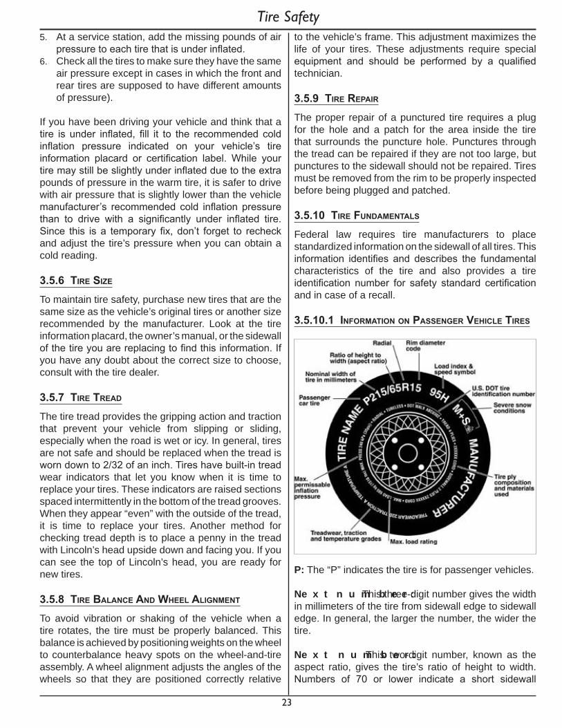
3.5.10.1 InformatIon on passenger VehICle tIres
P : The “P” indicates the tire is for passenger vehicles.
Ne x t n u m b e r : This three-digit number gives the width in millimeters of the tire from sidewall edge to sidewall edge. In general, the larger the number, the wider the tire.
Ne x t n u m b e r : This two-digit number, known as the aspect ratio, gives the tire’s ratio of height to width. Numbers of 70 or lower indicate a short sidewall
Tire Safety

24
for improved steering response and better overall handling on dry pavement.
R: The “R” stands for radial. Radial ply construction of tires has been the industry standard for the past 20 years.
Ne x t n u m b e r : This two-digit number is the wheel or rim diameter in inches. If you change your wheel size, you will have to purchase new tires to match the new wheel diameter.
Ne x t n u m b e r : This two- or three-digit number is the tire’s load index. It is a measurement of how much weight each tire can support. You may find this information in your owner’s manual. If not, contact a local tire dealer. Note: You may not find this information on all tires because it is not required by law.
M + S : The “M+S” or “M/S” indicates that the tire has some mud and snow capability. Most radial tires have these markings; hence, they have some mud and snow capability.
S p e e d Ra t i n g : The speed rating denotes the speed at which a tire is designed to be driven for extended periods of time.
Note: You may not find this information on all tires because it is not required by law.
U.S. DOT Tire Identification Number: This begins with the letters “DOT” and indicates that the tire meets all federal standards. The next two numbers or letters are the plant code where it was manufactured, and the last four numbers represent the week and year the tire was built. For example, the numbers 3197 means the 31st week of 1997. The other numbers are marketing codes used at the manufacturer’s discretion. This information is used to contact consumers if a tire defect requires a recall.
T i r e P l y C o m p o s i t i o n a n d M a t e r i a l s U s e d : The number of plies indicates the number of layers of rubber-coated fabric in the tire. In general, the greater the number of plies, the more weight a tire can support. Tire manufacturers also must indicate the materials in the tire, which include steel, nylon, polyester, and others.
M a x i m u m L o a d Ra t i n g : This number indicates the maximum load in kilograms and pounds that can be carried by the tire.
Maximum Permissible Inflation Pressure: This number is the greatest amount of air pressure that should ever be put in the tire under normal driving conditions.
3.5.10.2 U T Q GS In f o r m a t i o n
T r e a d w e a r Nu m b e r : This number indicates the tire’s wear rate. The higher the treadwear number is, the longer it should take for the tread to wear down. For example, a tire graded 400 should last twice as long as a tire graded 200.
T r a c t i o n L e t t e r : This letter indicates a tire’s ability to stop on wet pavement. A higher graded tire should allow you to stop your car on wet roads in a shorter distance than a tire with a lower grade. Traction is graded from highest to lowest as “AA”, “A”, “B”, and “C”.
T e m p e r a t u r e L e t t e r : This letter indicates a tire’s resistance to heat. The temperature grade is for a tire that is inflated properly and not overloaded. Excessive speed, under inflation or excessive loading, either separately or in combination, can cause heat build-up and possible tire failure. From highest to lowest, a tire’s resistance to heat is graded as “A”, “B”, or “C”.
3.5.10.3 Ad d i t i o n a l In f o r m a t i o n O n L i g h t T r u c k T i r e s
Tires for light trucks have other markings besides those found on the sidewalls of passenger tires.
L T : The “LT” indicates the tire is for light trucks or trailers.
Tire Safety

25
S T : An “ST” is an indication the tire is for trailer use only.
M a x . L o a d D u a l k g ( l b s ) a t k P a ( p s i ) C o l d : This information indicates the maximum load and tire pressure when the tire is used as a dual, that is, when four tires are put on each rear axle (a total of six or more tires on the vehicle).
M a x . L o a d S i n g l e k g ( l b s ) a t k P a ( p s i ) C o l d : This information indicates the maximum load and tire pressure when the tire is used as a single.
L o a d Ra n g e : This information identifies the tire’s load-carrying capabilities and its inflation limits.
3.5.10.4 T i r e S a f e t y T i p s
P r e v e n t i n g T i r e D a m a g e• Slow down if you have to go over a pothole or other
object in the road.• Do not run over curbs or other foreign objects in
the roadway, and try not to strike the curb when parking.
T i r e S a f e t y C h e c k l i s t• Check tire pressure regularly (at least once a
month), including the spare.• Inspect tires for uneven wear patterns on the tread,
cracks, foreign objects, or other signs of wear or trauma.
• Remove bits of glass and foreign objects wedged in the tread.
• Make sure your tire valves have valve caps.• Check tire pressure before going on a long trip.• Do not overload your vehicle. Check the Tire
Information Placard or Owner’s Manual for the maximum recommended load for the vehicle.
Tire Safety
26
4. CouplIng and unCouplIng
Follow all of the safety precautions and instructions in this manual to ensure safety of persons, cargo, and satisfactory life of the T-Ramp.
4.1 tow VehICle and hItCh
If the vehicle and hitch are not properly selected and matched to the Gross Vehicle Weight Rating (GVWR) of your T-Ramp, you can cause an accident that could lead to death or serious injury. If you already have a tow vehicle, know your vehicle tow rating and make certain the T-Ramp’s rated capacity is less than or equal to the tow vehicle’s rated towing capacity.
^ D ANGE RU s e o f a t o w v e h i c l e w i t h a t o w i n g c a p a c i t y l e s s t h a n t h e l o a d r a t i n g o f t h e T - Ra m p c a n r e s u l t i n l o s s o f c o n t r o l , a n d m a y l e a d t o d e a t h o r s e r i o u s i n j u r y .
U s e o f a h i t c h w i t h a l o a d r a t i n g l e s s t h a n t h e l o a d r a t i n g o f t h e T - Ra m p c a n r e s u l t i n l o s s o f c o n t r o l a n d m a y l e a d t o d e a t h o r s e r i o u s i n j u r y .
V e r i f y h i t c h a n d t o w v e h i c l e a r e r a t e d f o r t h e Gr o s s V e h i c l e We i g h t Ra t i n g o f y o u r T - Ra m p .
4.1.1 t-ramp InformatIon
The Certification / Vehicle Identification Number (VIN) tag is located on the front left side of the T-Ramp.
The T-Ramp Certification / VIN tag contains the following critical safety information for the use of your trailer:
M ANU F AC T U RE R: Name of T-Ramp manufacturer.
D AT E O F M ANU F AC T U RE : Month and year the T-Ramp was manufactured.
GV WR: The Gross Vehicle Weight Rating is the maximum allowable gross weight of the T-Ramp and its contents. The gross weight of the T-Ramp includes the weight of the T-Ramp and all of the items within it (such as cargo and other supplies).
GAWR: The Gross Axle Weight Rating is the maximum gross weight that an axle can support. It is the lowest of axle, wheel, or tire rating. Sometimes the tire or wheel rating is lower than the axle manufacturers rating, and will then determine GAWR.
The sum total of the GAWR for axle may be less than the GVWR for the T-Ramp, because some of the load is carried by the tow vehicle. The total weight of the cargo and T-Ramp must not exceed the GVWR, and the load on axle must not exceed its GAWR.
T IRE S IZ E : The tire size and load range for your T-Ramp.
RIM S IZ E : The rim size and load range for your T-Ramp.
P S I: The tire air pressure (kPa / PSI) measured with tires cold.
V IN: The Vehicle Identification Number.
V E H IC L E T Y P E : Trailer.
C E RT IF IC AT IO N S T AT E M E NT : “This trailer meets all the Federal Motor Vehicle Safety Standards in effect on the date of manufacture shown above”.
4.1.2 tow VehICle
When equipping a new vehicle or an older vehicle to tow a T-Ramp, ask the vehicle dealer for advice on how to outfit the tow vehicle.
Vehicle manufacturers will provide you with the maximum towing capacities of their various models, as well as the GCWR.
4.2 tongue weIght
It is critical to have a portion of the T-Ramp load carried by the tow vehicle. The T-Ramp tongue must exert a downward force on the hitch. This is necessary for two reasons. First, the proper amount of tongue weight is necessary for the tow vehicle to be able to maintain control of the tow vehicle/trailer system.
If, for example, the tongue exerts an upward pull on the hitch, instead of pushing down on it because trailer is overloaded behind its axle, the rear wheel of the tow vehicle can lose traction or grip and cause loss of control. Also, even if there is some weight on the tongue, but not enough weight on the tongue, the trailer can become unstable.
Coupling And Uncoupling
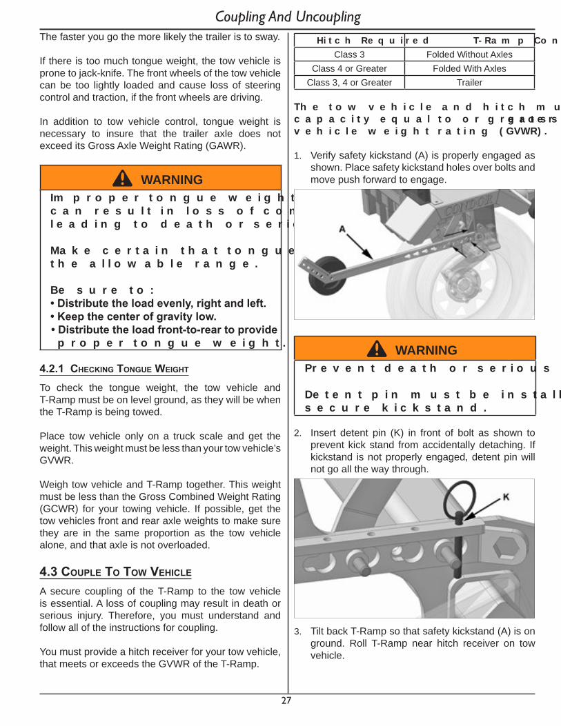
27
The faster you go the more likely the trailer is to sway.
If there is too much tongue weight, the tow vehicle is prone to jack-knife. The front wheels of the tow vehicle can be too lightly loaded and cause loss of steering control and traction, if the front wheels are driving.
In addition to tow vehicle control, tongue weight is necessary to insure that the trailer axle does not exceed its Gross Axle Weight Rating (GAWR).
^ WARNINGIm p r o p e r t o n g u e w e i g h t ( l o a d d i s t r i b u t i o n ) c a n r e s u l t i n l o s s o f c o n t r o l o f t h e T - Ra m p , l e a d i n g t o d e a t h o r s e r i o u s i n j u r y .
M a k e c e r t a i n t h a t t o n g u e w e i g h t i s w i t h i n t h e a l l o w a b l e r a n g e .
B e s u r e t o :•Distributetheloadevenly,rightandleft.•Keepthecenterofgravitylow.•Distributetheloadfront-to-reartoprovide
p r o p e r t o n g u e w e i g h t .
4.2.1 CheCkIng tongue weIght
To check the tongue weight, the tow vehicle and T-Ramp must be on level ground, as they will be when the T-Ramp is being towed.
Place tow vehicle only on a truck scale and get the weight. This weight must be less than your tow vehicle’s GVWR.
Weigh tow vehicle and T-Ramp together. This weight must be less than the Gross Combined Weight Rating (GCWR) for your towing vehicle. If possible, get the tow vehicles front and rear axle weights to make sure they are in the same proportion as the tow vehicle alone, and that axle is not overloaded.
4.3 Couple to tow VehICle
A secure coupling of the T-Ramp to the tow vehicle is essential. A loss of coupling may result in death or serious injury. Therefore, you must understand and follow all of the instructions for coupling.
You must provide a hitch receiver for your tow vehicle, that meets or exceeds the GVWR of the T-Ramp.
H i t c h Re q u i r e d T - Ra m p C o n f i g u r a t i o nClass 3 Folded Without Axles
Class 4 or Greater Folded With AxlesClass 3, 4 or Greater Trailer
T h e t o w v e h i c l e a n d h i t c h m u s t h a v e a r a t e d t o w i n g c a p a c i t y e q u a l t o o r g r e a t e r t h a n t h e T - Ra m p g r o s s v e h i c l e w e i g h t r a t i n g ( GV WR) .
1. Verify safety kickstand (A) is properly engaged as shown. Place safety kickstand holes over bolts and move push forward to engage.
^ WARNINGP r e v e n t d e a t h o r s e r i o u s i n j u r y .
D e t e n t p i n m u s t b e i n s t a l l e d a s s h o w n t o s e c u r e k i c k s t a n d .
2. Insert detent pin (K) in front of bolt as shown to prevent kick stand from accidentally detaching. If kickstand is not properly engaged, detent pin will not go all the way through.
3. Tilt back T-Ramp so that safety kickstand (A) is on ground. Roll T-Ramp near hitch receiver on tow vehicle.
Coupling And Uncoupling
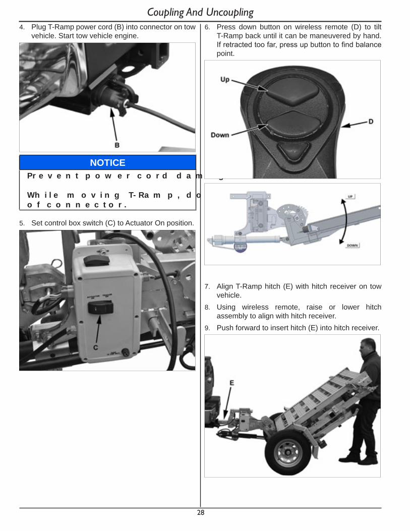
28
4. Plug T-Ramp power cord (B) into connector on tow vehicle. Start tow vehicle engine.
NO T IC EP r e v e n t p o w e r c o r d d a m a g e .
Wh i l e m o v i n g T - Ra m p , d o n o t p u l l c o r d o u t o f c o n n e c t o r .
5. Set control box switch (C) to Actuator On position.
6. Press down button on wireless remote (D) to tilt T-Ramp back until it can be maneuvered by hand. If retracted too far, press up button to find balance point.
7. Align T-Ramp hitch (E) with hitch receiver on tow vehicle.
8. Using wireless remote, raise or lower hitch assembly to align with hitch receiver.
9. Push forward to insert hitch (E) into hitch receiver.
Coupling And Uncoupling
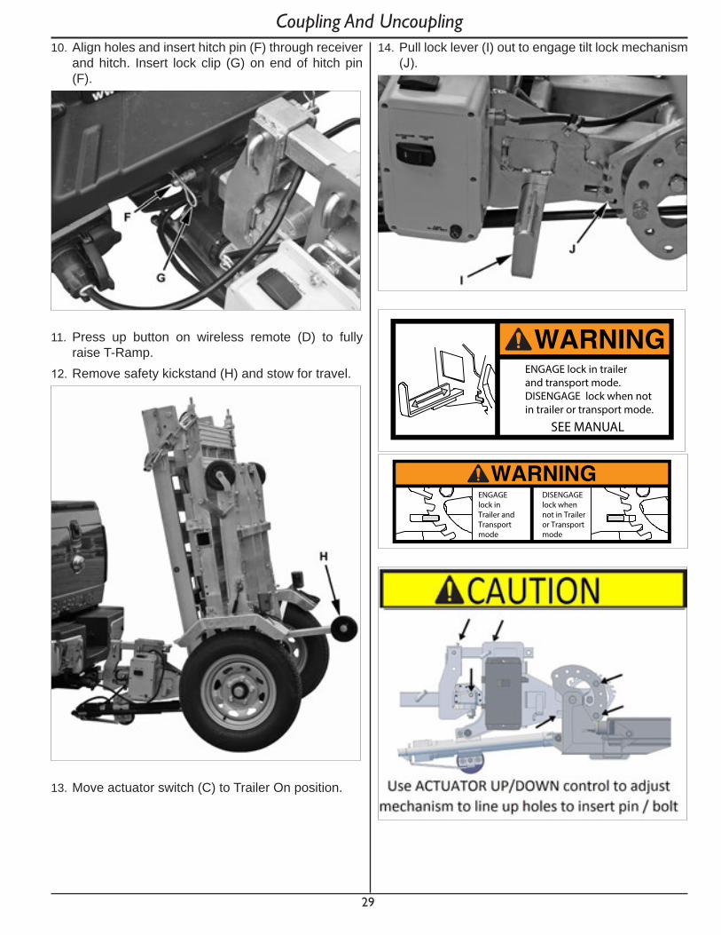
29
10. Align holes and insert hitch pin (F) through receiver and hitch. Insert lock clip (G) on end of hitch pin (F).
11. Press up button on wireless remote (D) to fully raise T-Ramp.
12. Remove safety kickstand (H) and stow for travel.
13. Move actuator switch (C) to Trailer On position.
14. Pull lock lever (I) out to engage tilt lock mechanism (J).
WARNINGENGAGE lock in trailerand transport mode.DISENGAGE lock when notin trailer or transport mode.
SEE MANUAL
WARNINGENGAGElock inTrailer andTransportmode
DISENGAGElock whennot in Traileror Transportmode
Coupling And Uncoupling

30
4.3.1 ConneCt safety Cables
1. Visually inspect safety cables and hooks for wear or damage. Replace worn or damaged safety cables and hooks before towing.
2. Safety cables must crisscross under the coupler so if the T-Ramp uncouples, safety cables can hold the tongue up above the road. Loop around a frame member of the tow vehicle or to holes provided in the hitch system. Do not attach them to an interchangeable part of the hitch assembly.
3. Attach hooks up from underneath the hole. Do not just drop into hole.
4. Provide enough slack in cables to permit tight turns, but not be close to the road surface to drag.
^ WARNINGIm p r o p e r r i g g i n g o f t h e s a f e t y c a b l e s c a n r e s u l t i n l o s s o f c o n t r o l o f t h e T - Ra m p a n d t o w v e h i c l e , l e a d i n g t o d e a t h o r s e r i o u s i n j u r y , i f t h e T - Ra m p u n c o u p l e s f r o m t h e t o w v e h i c l e .
C r o s s c a b l e s u n d e r h i t c h a n d c o u p l e r w i t h e n o u g h s l a c k t o p e r m i t t u r n i n g a n d t o h o l d t o n g u e u p , i f t h e T - Ra m p u n c o u p l e s .
F a s t e n c a b l e s t o f r a m e o f t o w v e h i c l e .
D o n o t f a s t e n c a b l e s t o a n y p a r t o f t h e h i t c h u n l e s s t h e h i t c h h a s h o l e s o r l o o p s specificallyforthatpurpose.
4.3.2 CheCk lIghts
1. Check all lights for proper operation. Repair or replace non-working lights before towing or hauling T-Ramp.
^ WARNINGIm p r o p e r e l e c t r i c a l c o n n e c t i o n b e t w e e n t h e t o w v e h i c l e a n d t h e T - Ra m p w i l l r e s u l t i n i n o p e r a b l e l i g h t s a n d c a n l e a d t o c o l l i s i o n .
V e r i f y t h a t a l l l i g h t s a n d t u r n s i g n a l s w o r k .
4.4 remoVe tIre/axle assemblIes
This procedure starts with T-Ramp attached to tow vehicle in the folded position with wheels installed and wheels off ground.
1. Remove lock clip (A) and pin (B).2. Disconnect light harness connector (C).
^ C AU T IO NT i r e / a x l e a s s e m b l y w e i g h s a p p r o x i m a t e l y 6 5 l b s .
P l a n a s a f e l i f t i n g p r o c e d u r e b e f o r e r e m o v i n g t i r e / a x l e a s s e m b l y .
Coupling And Uncoupling

31
3. Raise latch (D) and slide tire/axle assembly outward to remove. Repeat procedure for other side.
4. To install tire/axle assembly reverse steps 1-3.
4.5 unCouple t-ramp
This procedure starts with T-Ramp attached to tow vehicle in the folded position with wheels installed and wheels off ground.
SEE MANUAL FOR LOCK OPERATION INSTRUCTIONS
WARNINGBe Sure All Locks are fully engaged before attempting to move T-Ramp
1. Park on a firm level surface.2. Remove tie down straps.3. Install safety kickstand (A) to mounting studs and
push forward to engage.
^ WARNINGP r e v e n t d e a t h o r s e r i o u s i n j u r y .
D e t e n t p i n m u s t b e i n s t a l l e d a s s h o w n t o s e c u r e k i c k s t a n d .
4. Insert detent pin (K) in front of bolt as shown to prevent kick stand from accidentally detaching. If kickstand is not properly engaged, detent pin will not go all the way through.
5. Move switch (B) to Actuator On position.
6. Push lock lever (H) inward to disengage tilt lock mechanism (I).
Coupling And Uncoupling
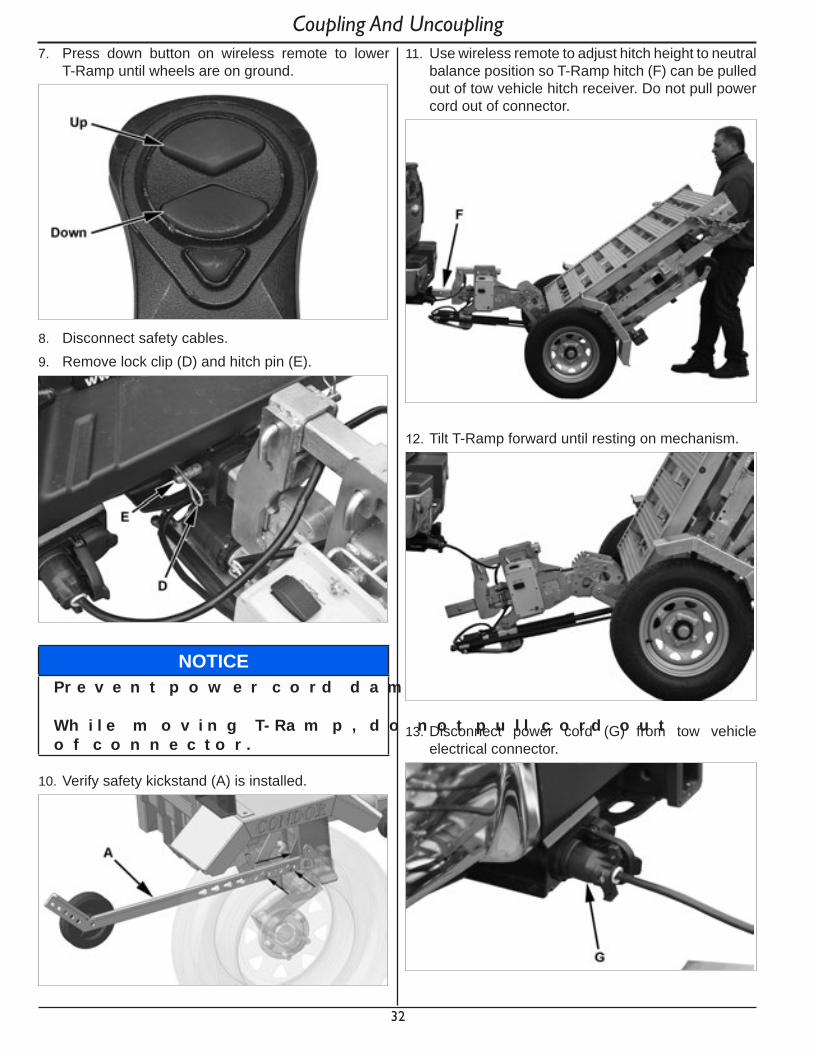
32
7. Press down button on wireless remote to lower T-Ramp until wheels are on ground.
8. Disconnect safety cables.9. Remove lock clip (D) and hitch pin (E).
NO T IC EP r e v e n t p o w e r c o r d d a m a g e .
Wh i l e m o v i n g T - Ra m p , d o n o t p u l l c o r d o u t o f c o n n e c t o r .
10. Verify safety kickstand (A) is installed.
Coupling And Uncoupling11. Use wireless remote to adjust hitch height to neutral
balance position so T-Ramp hitch (F) can be pulled out of tow vehicle hitch receiver. Do not pull power cord out of connector.
12. Tilt T-Ramp forward until resting on mechanism.
13. Disconnect power cord (G) from tow vehicle electrical connector.
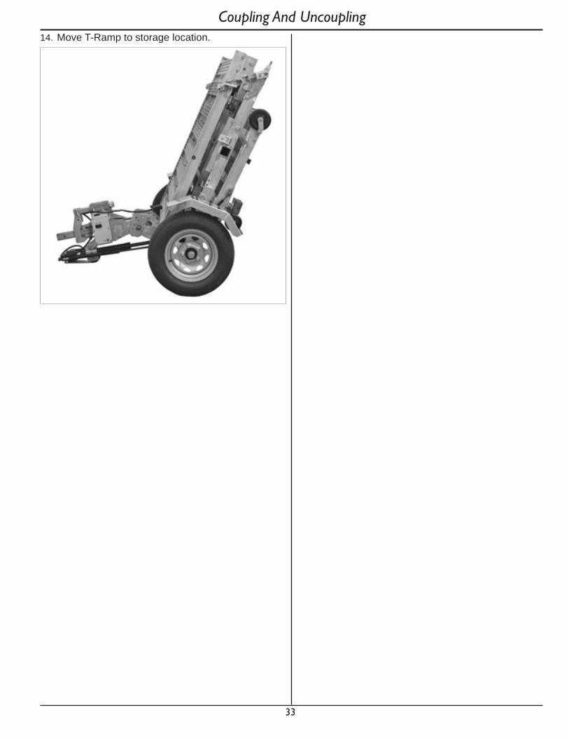
33
14. Move T-Ramp to storage location.
Coupling And Uncoupling

34
5. t-ramp operatIons
5.1 ramp and traIler ConfIguratIons 5.1.1 folded on tow VehICle
This procedure starts with T-Ramp attached to tow vehicle in the folded position with wheels on ground.
^ C AU T IO NP i n c h h a za r d .
Keepclearofpinchpointsduringo p e r a t i o n .
1. Move switch (A) to Actuator On position.
2. Press up button on wireless remote (B) to lift T-Ramp up into folded position.
3. Pull lock lever (C) out to engage tilt lock mechanism (D). Move switch (A) to Trailer On position.
T-Ramp Operations And Adjustments

35
T-Ramp Operations And Adjustments
WARNINGENGAGE lock in trailerand transport mode.DISENGAGE lock when notin trailer or transport mode.
SEE MANUAL
WARNINGENGAGElock inTrailer andTransportmode
DISENGAGElock whennot in Traileror Transportmode
4. Secure T-Ramp to tow vehicle using ratchet tie down straps.
5.1.2 ConfIgure t-ramp to ramp posItIon
This procedure starts with T-Ramp attached to tow vehicle in the folded position with wheels installed and wheels off the ground.
1. Remove lock clip (A) and pin (B). 2. Disconnect light harness connector (C).

36
T-Ramp Operations And Adjustments3. Raise latch (D) and slide tire/axle assembly outward
to remove. Repeat procedure for other side.
4. Set switch (E) to Actuator On position.
WARNINGBe sure all locks and pins are fullyengaged prior to transportSEE MANUAL FOR LOCK OPERATION INSTRUCTIONS
5. Pull pin (H) out and push latch (I) upward to release. Repeat for other side.
WARNINGBe sure all locks and pins are fullyengaged prior to transportSEE MANUAL FOR LOCK OPERATION INSTRUCTIONS
6. Remove lock clip and pin (F). Repeat for other side and lower rear ramp section (G) to ground.
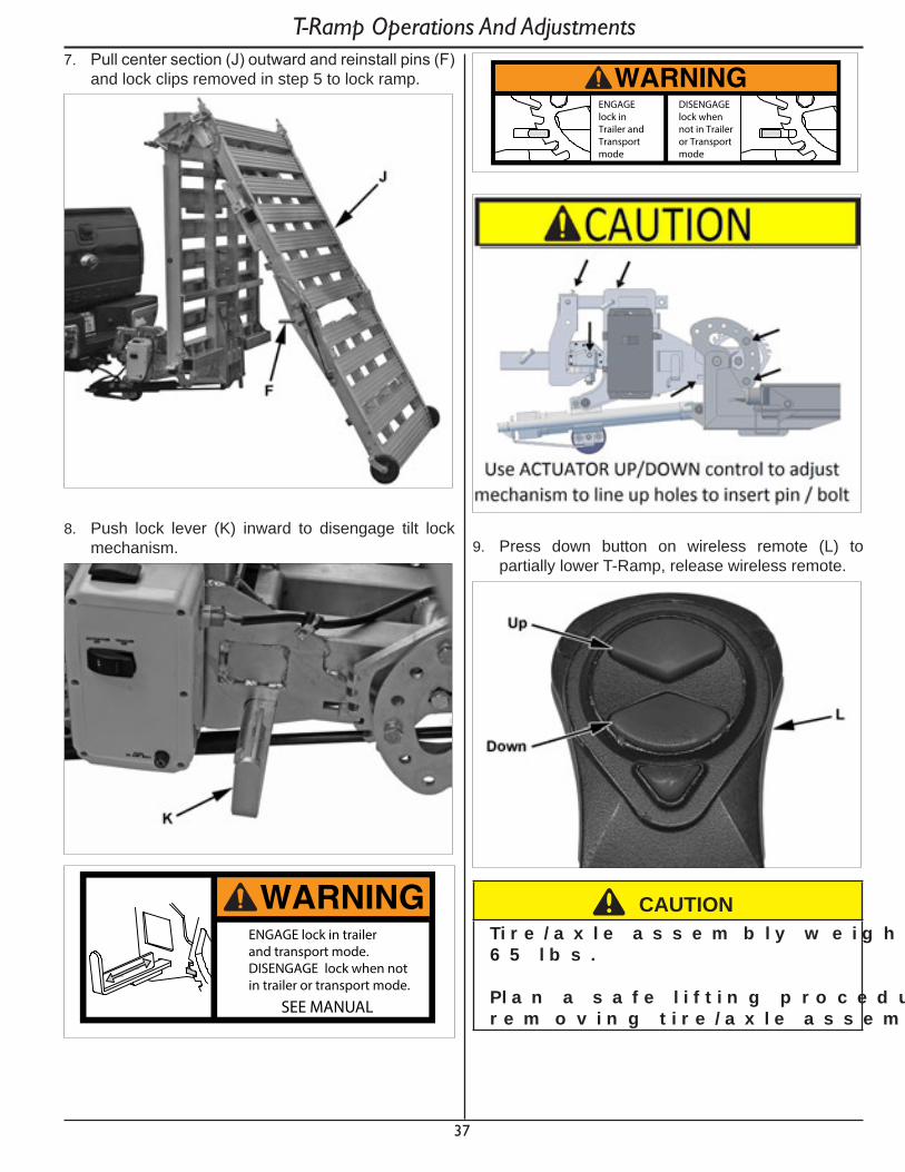
37
T-Ramp Operations And Adjustments7. Pull center section (J) outward and reinstall pins (F)
and lock clips removed in step 5 to lock ramp.
8. Push lock lever (K) inward to disengage tilt lock mechanism.
WARNINGENGAGE lock in trailerand transport mode.DISENGAGE lock when notin trailer or transport mode.
SEE MANUAL
WARNINGENGAGElock inTrailer andTransportmode
DISENGAGElock whennot in Traileror Transportmode
9. Press down button on wireless remote (L) to partially lower T-Ramp, release wireless remote.
^ C AU T IO NT i r e / a x l e a s s e m b l y w e i g h s a p p r o x i m a t e l y 6 5 l b s .
P l a n a s a f e l i f t i n g p r o c e d u r e b e f o r e r e m o v i n g t i r e / a x l e a s s e m b l y .

38
T-Ramp Operations And Adjustments10. Install tire/axle assemblies to center section.
Optional if using as a ramp only.
^ WARNINGAn i m p r o p e r l y s e c u r e d a x l e c a n r e s u l t i n d e a t h o r s e r i o u s i n j u r y .
V e r i f y a x l e s a r e l a t c h e d i n r e c e i v e r s .
11. Verify that latch (D) is engaged and connect trailer light harness connector (C).
12. Install tire/axle assembly pin (B) and lock clip (A). Repeat step 10-11 for other side.
13. Move wedge (I) on each side to ramp position.
14. Press down button on wireless remote to fully lower T-Ramp.
15. Move latch (J) toward T-Ramp while pressing up button on wireless remote (H) until latch clears lock.
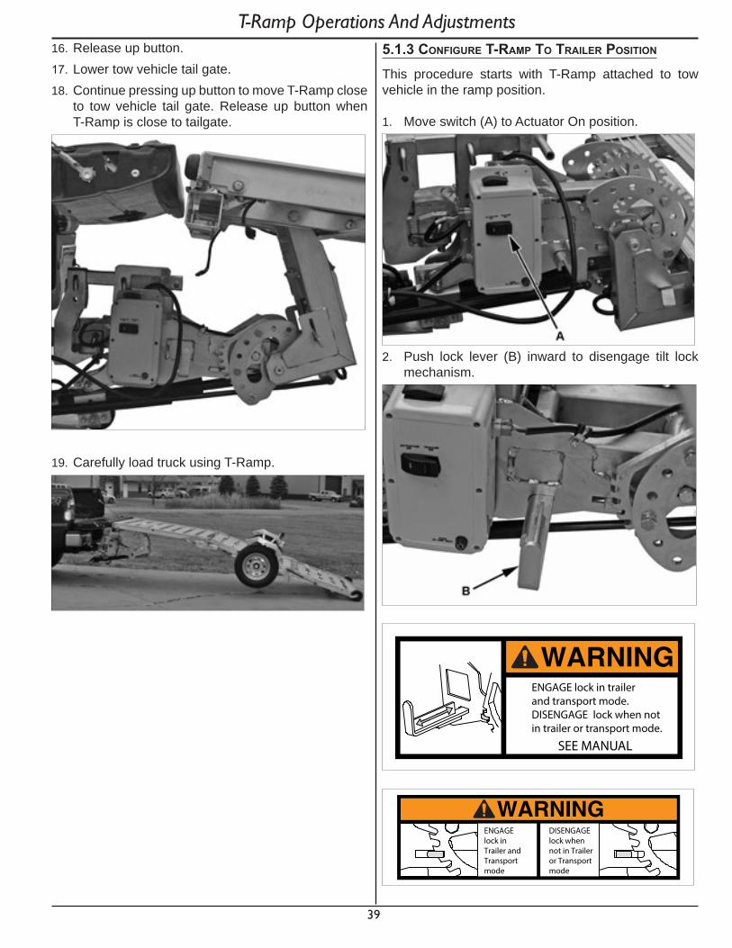
39
T-Ramp Operations And Adjustments16. Release up button.17. Lower tow vehicle tail gate.18. Continue pressing up button to move T-Ramp close
to tow vehicle tail gate. Release up button when T-Ramp is close to tailgate.
19. Carefully load truck using T-Ramp.
5.1.3 ConfIgure t-ramp to traIler posItIon
This procedure starts with T-Ramp attached to tow vehicle in the ramp position.
1. Move switch (A) to Actuator On position.
2. Push lock lever (B) inward to disengage tilt lock mechanism.
WARNINGENGAGE lock in trailerand transport mode.DISENGAGE lock when notin trailer or transport mode.
SEE MANUAL
WARNINGENGAGElock inTrailer andTransportmode
DISENGAGElock whennot in Traileror Transportmode
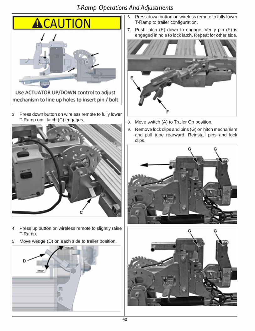
40
T-Ramp Operations And Adjustments
3. Press down button on wireless remote to fully lower T-Ramp until latch (C) engages.
4. Press up button on wireless remote to slightly raise T-Ramp.
5. Move wedge (D) on each side to trailer position.
6. Press down button on wireless remote to fully lower T-Ramp to trailer configuration.
7. Push latch (E) down to engage. Verify pin (F) is engaged in hole to lock latch. Repeat for other side.
8. Move switch (A) to Trailer On position.9. Remove lock clips and pins (G) on hitch mechanism
and pull tube rearward. Reinstall pins and lock clips.

41
T-Ramp Operations And Adjustments10. Remove lock clip and pin (H). Move T-Ramp
rearward, you will see a gap (I) between hitch mechanism and tube. Reinstall pin (H) and lock clip. T-Ramp is now ready to be pulled as a trailer.
5.1.4 rear ramp
1. To lower rear ramp to load position, remove lock clip and pin (A) on each side.
2. Lower rear ramp to load position.
3. To raise rear ramp to transport position, raise ramp and install pin (A) and lock clip on each side.
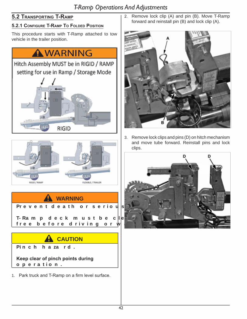
42
5.2 transportIng t-ramp
5.2.1 ConfIgure t-ramp to folded posItIon
This procedure starts with T-Ramp attached to tow vehicle in the trailer position.
^ WARNINGP r e v e n t d e a t h o r s e r i o u s i n j u r y .
T - Ra m p d e c k m u s t b e c l e a n , d r y a n d d e b r i s f r e e b e f o r e d r i v i n g o r w a l k i n g o n d e c k .
^ C AU T IO NP i n c h h a za r d .
Keepclearofpinchpointsduringo p e r a t i o n .
1. Park truck and T-Ramp on a firm level surface.
2. Remove lock clip (A) and pin (B). Move T-Ramp forward and reinstall pin (B) and lock clip (A).
3. Remove lock clips and pins (D) on hitch mechanism and move tube forward. Reinstall pins and lock clips.
T-Ramp Operations And Adjustments
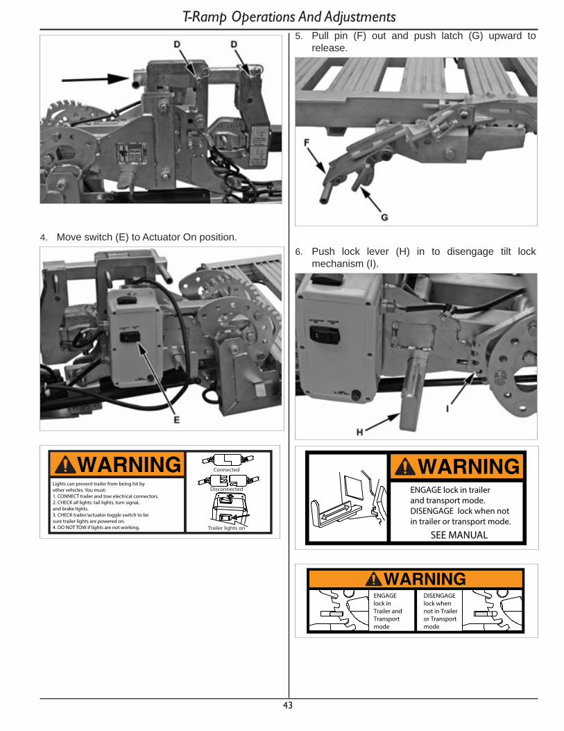
43
4. Move switch (E) to Actuator On position.
WARNING Connected
Disconnected
Trailer lights on
Lights can prevent trailer from being hit byother vehicles. You must:1. CONNECT trailer and tow electrical connectors.2. CHECK all lights: tail lights, turn signal, and brake lights.3. CHECK trailer/actuator toggle switch to be sure trailer lights are powered on.4. DO NOT TOW if lights are not working.
5. Pull pin (F) out and push latch (G) upward to release.
6. Push lock lever (H) in to disengage tilt lock mechanism (I).
WARNINGENGAGE lock in trailerand transport mode.DISENGAGE lock when notin trailer or transport mode.
SEE MANUAL
WARNINGENGAGElock inTrailer andTransportmode
DISENGAGElock whennot in Traileror Transportmode
T-Ramp Operations And Adjustments

44
7. Press up button on wireless remote to partially raise T-Ramp, release wireless remote.
^ C AU T IO NT i r e / a x l e a s s e m b l y w e i g h s a p p r o x i m a t e l y 6 5 l b s .
P l a n a s a f e l i f t i n g p r o c e d u r e b e f o r e r e m o v i n g t i r e / a x l e a s s e m b l y .
8. Remove lock clip (J) and pin (K).
9. Disconnect light harness connector (L).10. Raise latch (M) and slide tire/axle assembly outward
to remove. Repeat procedure for other side.
11. Press up button on wireless remote to lift T-Ramp up into folded position.
12. Pull lock lever (H) out to engage tilt lock mechanism (I). Move switch (E) to Trailer On position.
T-Ramp Operations And Adjustments

45
WARNINGENGAGE lock in trailerand transport mode.DISENGAGE lock when notin trailer or transport mode.
SEE MANUAL
WARNINGENGAGElock inTrailer andTransportmode
DISENGAGElock whennot in Traileror Transportmode
13. Remove lock clip and pin (N). Repeat for other side. Allow center section (O) to move against front section.
T-Ramp Operations And Adjustments
14. Push latch (F) down to engage. Verify pin (G) is engaged in hole to lock latch. Repeat for other side.
WARNINGBe sure all locks and pins are fullyengaged prior to transportSEE MANUAL FOR LOCK OPERATION INSTRUCTIONS
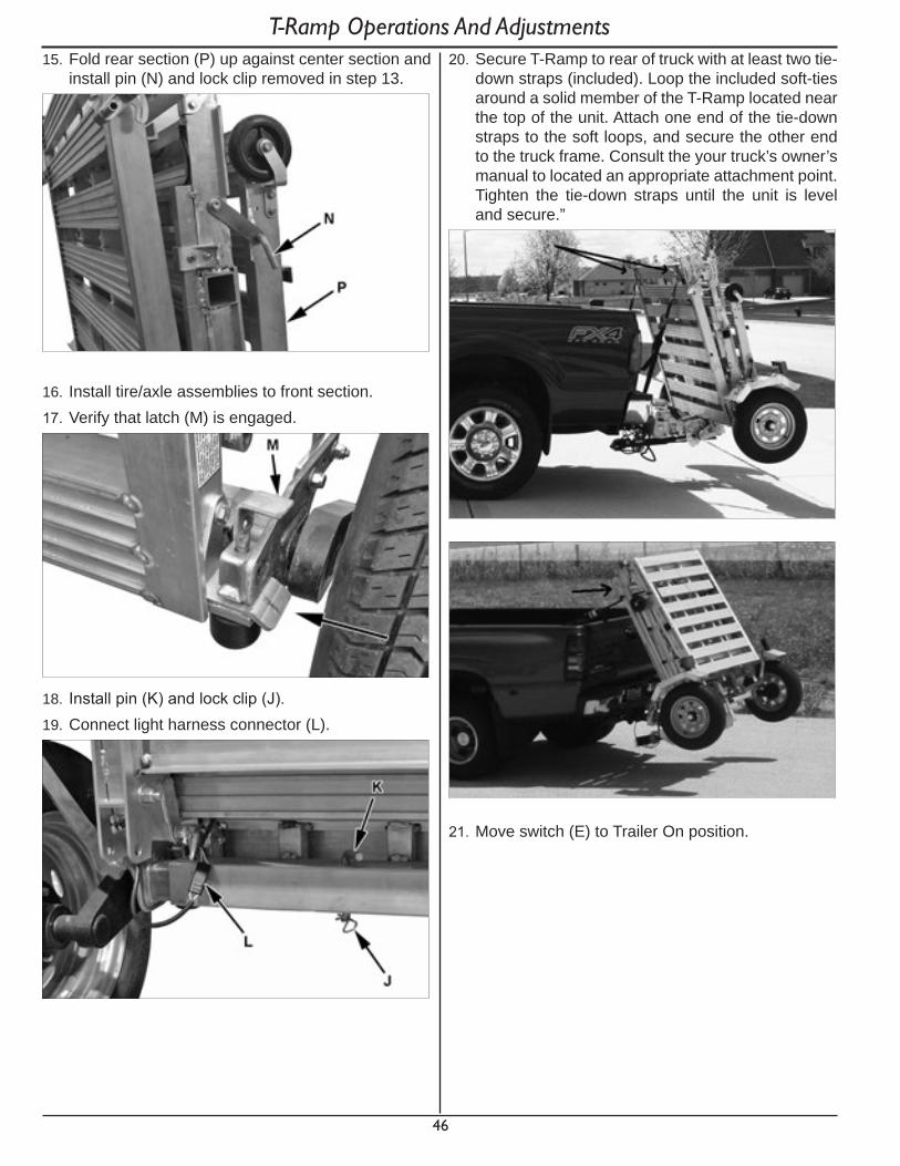
46
15. Fold rear section (P) up against center section and install pin (N) and lock clip removed in step 13.
16. Install tire/axle assemblies to front section.17. Verify that latch (M) is engaged.
18. Install pin (K) and lock clip (J). 19. Connect light harness connector (L).
20. Secure T-Ramp to rear of truck with at least two tie-down straps (included). Loop the included soft-ties around a solid member of the T-Ramp located near the top of the unit. Attach one end of the tie-down straps to the soft loops, and secure the other end to the truck frame. Consult the your truck’s owner’s manual to located an appropriate attachment point. Tighten the tie-down straps until the unit is level and secure.”
21. Move switch (E) to Trailer On position.
T-Ramp Operations And Adjustments
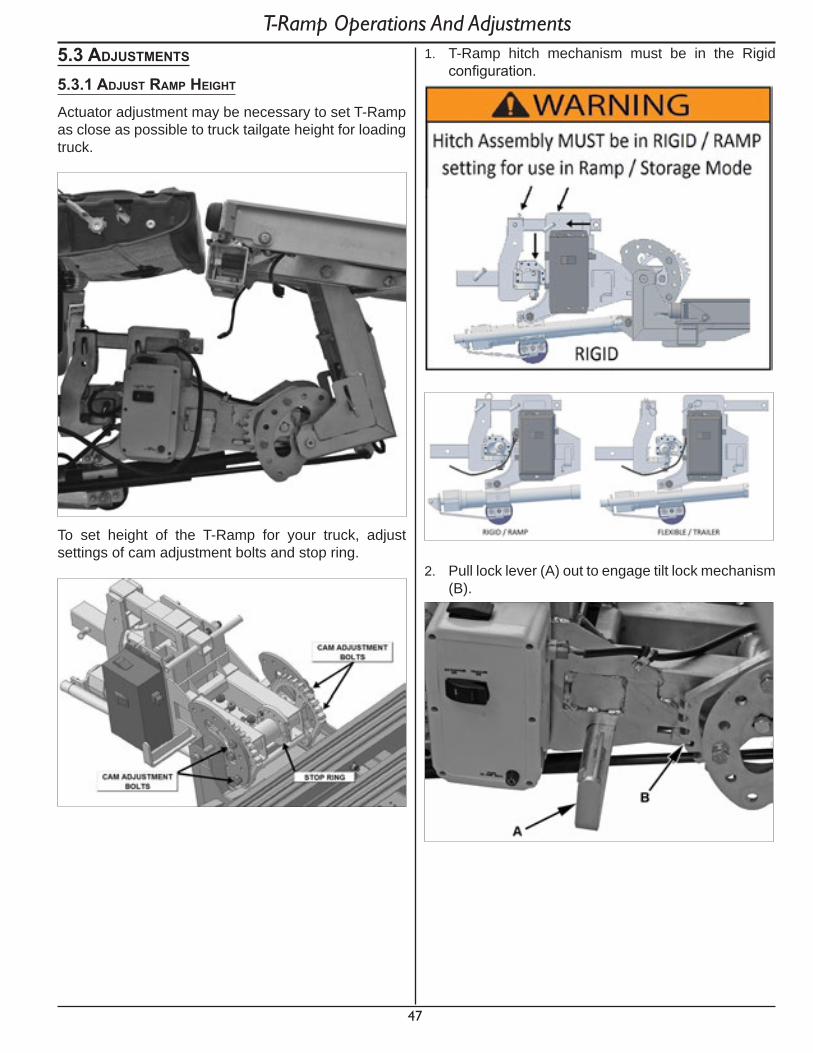
47
5.3 adjustments
5.3.1 adjust ramp heIght
Actuator adjustment may be necessary to set T-Ramp as close as possible to truck tailgate height for loading truck.
To set height of the T-Ramp for your truck, adjust settings of cam adjustment bolts and stop ring.
1. T-Ramp hitch mechanism must be in the Rigid configuration.
2. Pull lock lever (A) out to engage tilt lock mechanism (B).
T-Ramp Operations And Adjustments
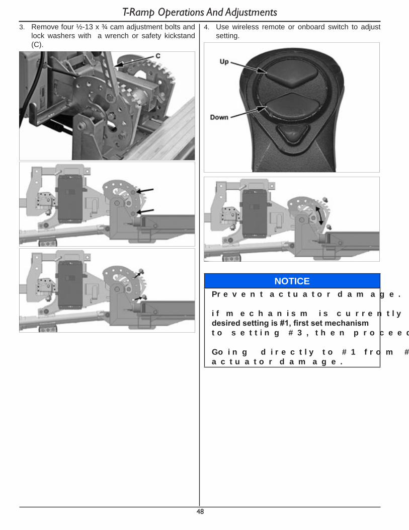
48
3. Remove four ½-13 x ¾ cam adjustment bolts and lock washers with a wrench or safety kickstand (C).
4. Use wireless remote or onboard switch to adjust setting.
NO T IC EP r e v e n t a c t u a t o r d a m a g e .
i f m e c h a n i s m i s c u r r e n t l y i n s e t t i n g # 5 , a n d desiredsettingis#1,firstsetmechanismt o s e t t i n g # 3 , t h e n p r o c e e d t o s e t t i n g # 1 .
Go i n g d i r e c t l y t o # 1 f r o m # 5 c a n c a u s e a c t u a t o r d a m a g e .
T-Ramp Operations And Adjustments
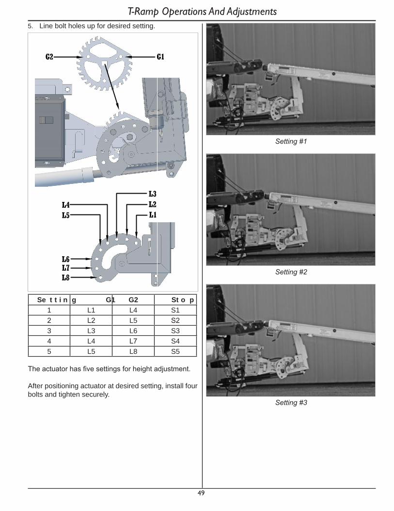
49
5. Line bolt holes up for desired setting.
S e t t i n g G1 G2 S t o p1 L1 L4 S12 L2 L5 S23 L3 L6 S34 L4 L7 S45 L5 L8 S5
The actuator has five settings for height adjustment.
After positioning actuator at desired setting, install fourbolts and tighten securely.
Setting #1
Setting #2
Setting #3
T-Ramp Operations And Adjustments
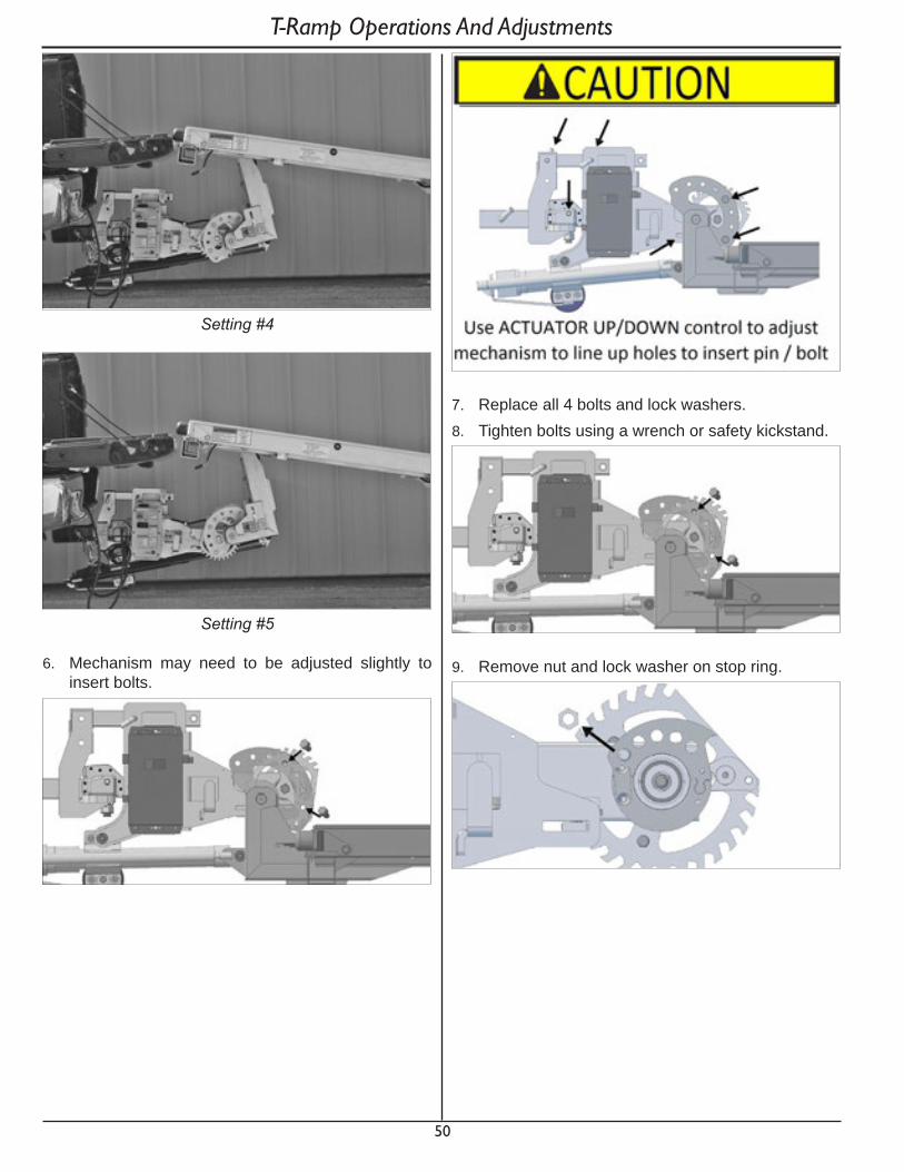
50
Setting #4
Setting #5
6. Mechanism may need to be adjusted slightly to insert bolts.
7. Replace all 4 bolts and lock washers.8. Tighten bolts using a wrench or safety kickstand.
9. Remove nut and lock washer on stop ring.
T-Ramp Operations And Adjustments

51
10. Pull stop ring off bolt and rotate to correct setting according to setting chart.
S e t t i n g G1 G2 S t o p1 L1 L4 S12 L2 L5 S23 L3 L6 S34 L4 L7 S45 L5 L8 S5
11. Push stop ring back onto bolt and replace nut and lock washer. Tighten nut.
T-Ramp Operations And Adjustments5.3.2 adjust traIler heIght
To set height of the T-Ramp for your truck, adjust settings of cam adjustment bolts and stop ring.
1. T-Ramp hitch mechanism must be in the Rigid configuration.
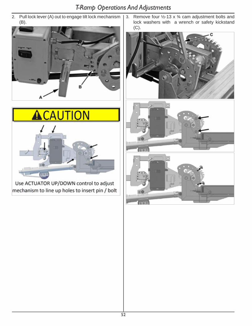
52
T-Ramp Operations And Adjustments2. Pull lock lever (A) out to engage tilt lock mechanism
(B). 3. Remove four ½-13 x ¾ cam adjustment bolts and
lock washers with a wrench or safety kickstand (C).
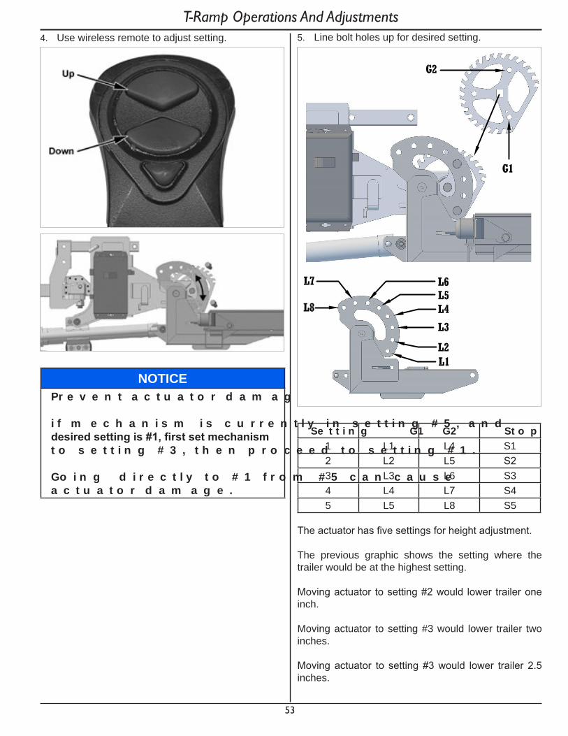
53
4. Use wireless remote to adjust setting.
NO T IC EP r e v e n t a c t u a t o r d a m a g e .
i f m e c h a n i s m i s c u r r e n t l y i n s e t t i n g # 5 , a n d desiredsettingis#1,firstsetmechanismt o s e t t i n g # 3 , t h e n p r o c e e d t o s e t t i n g # 1 .
Go i n g d i r e c t l y t o # 1 f r o m # 5 c a n c a u s e a c t u a t o r d a m a g e .
T-Ramp Operations And Adjustments5. Line bolt holes up for desired setting.
S e t t i n g G1 G2 S t o p1 L1 L4 S12 L2 L5 S23 L3 L6 S34 L4 L7 S45 L5 L8 S5
The actuator has five settings for height adjustment.
The previous graphic shows the setting where the trailer would be at the highest setting.
Moving actuator to setting #2 would lower trailer one inch.
Moving actuator to setting #3 would lower trailer two inches.
Moving actuator to setting #3 would lower trailer 2.5 inches.
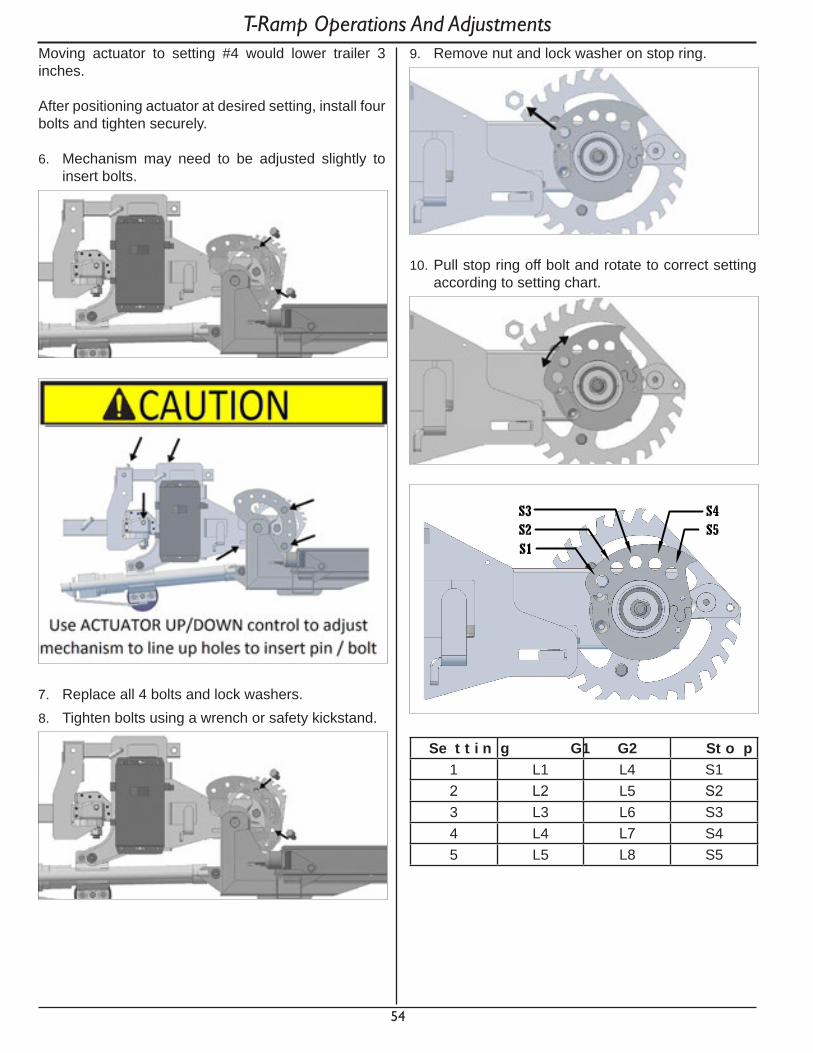
54
Moving actuator to setting #4 would lower trailer 3 inches.
After positioning actuator at desired setting, install four bolts and tighten securely.
6. Mechanism may need to be adjusted slightly to insert bolts.
7. Replace all 4 bolts and lock washers.8. Tighten bolts using a wrench or safety kickstand.
T-Ramp Operations And Adjustments9. Remove nut and lock washer on stop ring.
10. Pull stop ring off bolt and rotate to correct setting according to setting chart.
S e t t i n g G1 G2 S t o p1 L1 L4 S12 L2 L5 S23 L3 L6 S34 L4 L7 S45 L5 L8 S5
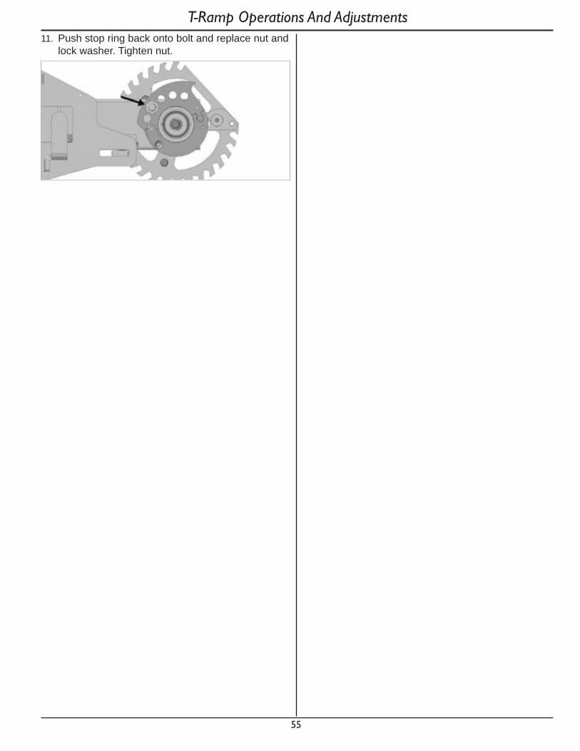
55
T-Ramp Operations And Adjustments11. Push stop ring back onto bolt and replace nut and
lock washer. Tighten nut.
56
Loading And Unloading6. loadIng and unloadIng
Improper trailer loading causes many accidents and deaths. To safely load a trailer, you must consider:• Overall load weight.• Load weight distribution.• Proper tongue weight.• Securing load properly.
To determine that you have loaded the trailer within its rating, you must consider the distribution of weight, as well as the total weight of the trailer and its contents. The trailer axle carries most of the total weight of the trailer and its contents (Gross Vehicle Weight, or “GVW”). The remainder of the total weight is carried by the tow vehicle hitch.
It is essential for safe towing that the trailer tongue and tow vehicle hitch carry the proper amount of the loaded trailer weight, otherwise the trailer can develop an undesirable sway at towing speeds, or the rear of the towing vehicle can be overloaded. Read the “Tongue Weight” information in Section 4.
The load distribution must be such that no component part of the trailer is loaded beyond its rating. You must consider the rating of the tires, wheels and axle.
Towing stability also depends on keeping the center of gravity as low as possible. Load heavy items over the axle. When loading additional items, be sure to maintain even side-to-side weight distribution and proper tongue weight. The total weight of the trailer and its contents must never exceed the total weight rating of the trailer (Gross Vehicle Weight Rating, or “GVWR”).
Do not transport people, containers of hazardous substances, or flammable liquids. The exception is fuel in the tank of vehicles or equipment being hauled.
^ WARNINGDonottransportflammable,explosive,p o i s o n o u s o r o t h e r d a n g e r o u s m a t e r i a l s o n y o u r t r a i l e r .
T h e e x c e p t i o n i s f u e l i n t h e t a n k o f e q u i p m e n t b e i n g h a u l e d .
^ WARNINGD o n o t t r a n s p o r t p e o p l e o n y o u r t r a i l e r . B e s i d e s p u t t i n g t h e i r l i v e s a t r i s k , t h e t r a n s p o r t o f p e o p l e o n a t r a i l e r i s i l l e g a l .
6.1 loadIng
1. Inspect trailer for damage.
^ WARNINGL o o s e c a r g o c a n s h i f t t h e c e n t e r o f g r a v i t y , a n d r e s u l t i n l o s s o f c o n t r o l o f t h e t r a i l e r .
D o n o t u s e a d a m a g e d o r l o o s e t i e d o w n s o r t r a c k t o s e c u r e c a r g o .
2. Park tow vehicle and Trailer On a firm and level surface.
3. Clear area around trailer.4. Position T-Ramp in desired configuration as
described in section 5.5. Load T-Ramp or use as a ramp to load tow vehicle.
See section 5.6. Verify T-Ramp is not overloaded and weight is
distributed properly. See section 5.7. Prepare T-Ramp for transport. See section 5.
6.2 seCurIng Cargo
^ WARNINGS h i f t i n g c a r g o c a n r e s u l t l o s s o f c o n t r o l a n d c a n l e a d t o d e a t h o r s e r i o u s i n j u r y .
T i e d o w n a l l l o a d s w i t h p r o p e r s i ze d f a s t e n e r s , c h a i n s , s t r a p s , e t c .
Refer to www.fmcsa.dot.gov for regulations regarding cargo securement rules.
57
Loading And Unloading6.3 unload
1. Park tow vehicle and T-ramp on a firm and level surface.
2. Clear the area around the T-Ramp.3. Remove chains, straps and tensioning devices.4. Position T-Ramp in desired configuration as
described in section 5.5. Unload T-Ramp or use as a ramp to unload tow
vehicle. See section 5.6. Prepare T-Ramp for transport. See section 5.

58
7. pre-tow CheCklIst
7.1 pre-tow CheCklIst
Before towing, double-check all of these items:• Tires, wheels and lug bolts. See Breaking In A New
T-Ramp and Inspection, Service and Maintenance section of this manual.
• Check that all wheel locks and pins are fully engaged and secured with hitch pin clips. See T-Ramp Operation And Adjustment section of this manual.
• Tire Pressure. Inflate tires on trailer and tow vehicle to the pressure stated on the Certification / VIN label.
• T-Ramp is secured to tow vehicle. See Coupling And Uncoupling section of this manual.
• Safety cables properly rigged to tow vehicle. See Coupling And Uncoupling section of this manual.
• Check that toggle switch on control box is set to Trailer On. See T-Ramp Operation And Adjustment section of this manual.
• Check that all lamps and connectors are fully attached and secure.
• Verify all lights work.• Cargo properly loaded, balanced and tied down.
See the appropriate “Loading And Unloading” section of this manual.
• Tongue weight and weight distribution set-up.• Verify flares and reflectors are available in tow
vehicle.• Check that all lock pins are in place and secured
with hitch pin clips. See T-Ramp Operation And Adjustment section of this manual.
• Check that main lock tube is disengaged and in trailer mode. See T-Ramp Operation And Adjustment section of this manual.
• Check that hitch ball is in the flexible / trailer mode. See T-Ramp Operation And Adjustment section of this manual.
• Check that all lock pins are in place and secured with hitch pin clips. See T-Ramp Operation And Adjustment section of this manual.
Pre-Tow Checklist7.2 make regular stops
After each 50 miles, or one hour of towing, stop and check the following items:• Coupling to tow vehicle is secure.• Safety cables are fastened and not dragging.• Cargo secured.
59
8. break In8.1 retIghten lugs at fIrst 10, 25 & 50 mIles
Wheel lug bolts can shift and settle quickly after being first assembled, and must be checked after the first 10, 25 and 50 miles of driving. Failure to perform this check may result in a wheel coming loose from the trailer, causing a crash leading to death or serious injury. Improper tightening of the lug bolts voids the warranty.
Refer to the Inspection, Service and Maintenance section of this manual.
^ WARNINGL u g b o l t s a r e p r o n e t o l o o s e n a f t e r b e i n g firstassembled.Deathorseriousinjuryc a n r e s u l t .
C h e c k l u g b o l t s f o r t i g h t n e s s o n a n e w T - Ra m p , a n d a f t e r r e - m o u n t i n g a w h e e l a t 1 0 , 2 5 a n d 5 0 m i l e s .
Break In

60
9. InspeCtIon, serVICe and maIntenanCe
9.1 InspeCtIon, serVICe and maIntenanCe summary Charts
You must inspect, maintain and service your T-Ramp regularly to insure safe and reliable operation. If you cannot or are unsure how to perform the items listed here, have your dealer do them. Note: In addition to this manual, also check the relevant component manufacturer’s manual.
In s p e c t i o n An d S e r v i c e B e f o r e E a c h T o wIt e m D e s c r i p t i o n In s p e c t i o n / S e r v i c e
1 Safety Cables and Hooks Check for wear and damage, Check bolts for tightness.2 Tires Check tire pressure when cold, inflate as needed
Check for damage (See Section 9.2.5)3 Wheels, Lug Bolts, and Hub Check for tightness (See Section 9.2.8)
Tighten. For new and remounted wheels, check tightness after first 10, 25, and 50 miles of driving, and after any impactCheck that all wheel locks and pins are fully engaged and secured with hitch pin clips. (See Section 5.1)
4 Lights, Wiring Check all lights for functionality and running illumination.Check that the toggle switch on the control box is set to Trailer On. (See Section 5.1)Check that all lamps and connectors are fully attached and secure.
5 Hitch Assembly Check that all lock pins are in place and secured with hitch pin clips. (See Section 5.1)Check that main lock tube is disengaged and in trailer mode. (See Section 5.1)Check that hitch ball is in the flexible / trailer mode. (See Section 5.1)
6 Section Locks Check that all lock pins are in place and secured with hitch pin clips. (See Section 5.1)Check that all locks are properly engaged, adjusted, and secured. (See Section 5.1)
In s p e c t i o n An d S e r v i c e E v e r y M o n t hIt e m D e s c r i p t i o n In s p e c t i o n / S e r v i c e
4 Wiring Harness and Connectors
Inspect for defects.
7 Deck Section Pivot Points Lubricate with approved spray silicone.8 Ball Hitch Assembly Pump marine grade grease into zerk fitting until ball chamber is overfilled.9 Locking Nuts on Stop Ring Check for tightness.10 Gas Shocks Lubricate with approved spray silicone between ball and mounted ends.11 Locks and Moving Parts Lubricate with approved spray silicone.
Inspection, Service And Maintenance
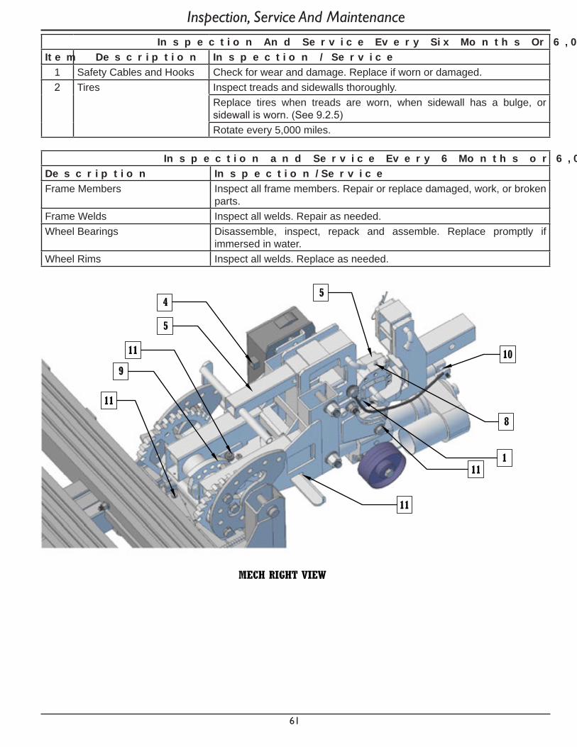
61
In s p e c t i o n An d S e r v i c e E v e r y S i x M o n t h s O r 6 , 0 0 0 M i l e sIt e m D e s c r i p t i o n In s p e c t i o n / S e r v i c e
1 Safety Cables and Hooks Check for wear and damage. Replace if worn or damaged.2 Tires Inspect treads and sidewalls thoroughly.
Replace tires when treads are worn, when sidewall has a bulge, or sidewall is worn. (See 9.2.5)Rotate every 5,000 miles.
In s p e c t i o n a n d S e r v i c e E v e r y 6 M o n t h s o r 6 , 0 0 0 M i l e sD e s c r i p t i o n In s p e c t i o n / S e r v i c eFrame Members Inspect all frame members. Repair or replace damaged, work, or broken
parts.Frame Welds Inspect all welds. Repair as needed.Wheel Bearings Disassemble, inspect, repack and assemble. Replace promptly if
immersed in water.Wheel Rims Inspect all welds. Replace as needed.
Inspection, Service And Maintenance
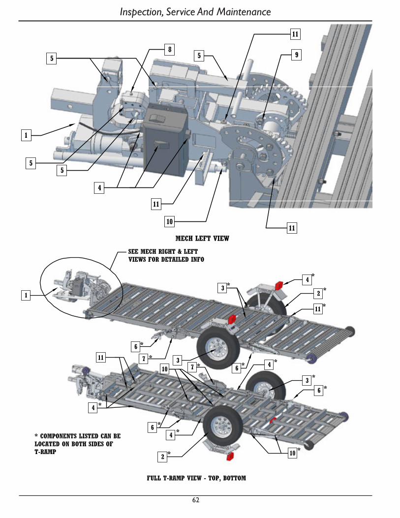
62
Inspection, Service And Maintenance

63
Inspection, Service And Maintenance9.2 InspeCtIon and serVICe InstruCtIons
^ WARNINGWo r n o r b r o k e n s u s p e n s i o n p a r t s c a n c a u s e l o s s o f c o n t r o l a n d i n j u r y m a y r e s u l t .
H a v e T - Ra m p p r o f e s s i o n a l l y i n s p e c t e d a n n u a l l y a n d a f t e r a n y i m p a c t .
To perform many of the inspection and maintenance activities, you must jack up the trailer.
When jacking and using jack stands, place them so as to clear wiring and suspension parts. Place jacks and jack stands under the outer frame rail to which the axles are attached.
^ WARNINGNevergounderT-Rampunlessitisonfirma n d l e v e l g r o u n d a n d r e s t i n g o n p r o p e r l y p l a c e d a n d s e c u r e d j a c k s t a n d s .
^ WARNINGC r u s h i n g h a z a r d .
T h e t o w v e h i c l e a n d T - Ra m p c o u l d b e i n a d v e r t e n t l y m o v e d w h i l e a p e r s o n i s u n d e r t h e T - Ra m p .
T h e t o w v e h i c l e e n g i n e m u s t b e o f f , i g n i t i o n k e y r e m o v e d a n d p a r k i n g b r a k e s s e t b e f o r e e n t e r i n g t h e a r e a u n d e r t h e T - Ra m p .
9.2.1 t-ramp struCture
Wash T-Ramp as needed with a power washer and a detergent solution.
9.2.1.1 fasteners and frame members
Inspect all fasteners and structural frame members for bending and other damage, cracks, or failure. Repair or replace any damaged fastener and repair the frame member. If you have any questions about the condition or method of repair of fasteners or frame members, get the recommendation of, or have the repair done by your dealer.
^ WARNINGB r o k e n o r d a m a g e d f a s t e n e r s c a n c a u s e i n j u r y o r d a m a g e t o t r a i l e r a n d c o n t e n t s .
In s p e c t f o r , a n d r e p a i r a l l d a m a g e d p a r t s a t l e a s t o n c e a y e a r .
9.2.1.2 welds
All welds can crack or fail when subjected to heavy loads or movement of cargo that was not properly secured. Any time that you know or suspect that the trailer has been subjected to heavy loads or movement of cargo, immediately inspect the welds and fasteners for damage. To prevent severe damage to T-Ramp, inspect all welds for cracks or failure at least once a year. If a weld failure is detected, contact your dealer.
^ WARNINGD o n o t a t t e m p t t o r e p a i r a c r a c k e d o r b r o k e n w e l d u n l e s s y o u h a v e t h e s k i l l s a n d e q u i p m e n t t o m a k e t h e r e p a i r .
Im p r o p e r w e l d r e p a i r w i l l l e a d t o e a r l y f a i l u r e o f t h e T - Ra m p s t r u c t u r e a n d s e r i o u s i n j u r y o r d e a t h .
S e e y o u r d e a l e r f o r w e l d r e p a i r s .
9.2.2 lIghts and sIgnals
Before each tow, check all lights for proper operation.
^ WARNINGT o a v o i d r i s k o f c o l l i s i o n s , a l l l i g h t s m u s t w o r k .
9.2.3 wheel rIms
If the T-Ramp has been struck, or impacted, on or near the wheels, or if wheels have struck a curb, inspect the rims for damage. Replace any damaged wheel. Inspect the wheels for damage every year, even if no obvious impact has occurred.
9.2.4 tIres
Before each tow, check the tire pressure to make sure it is at the level indicated on the tire sidewall or VIN label. Tire pressure must be checked while the tire is cold. Do not check tire pressure immediately after
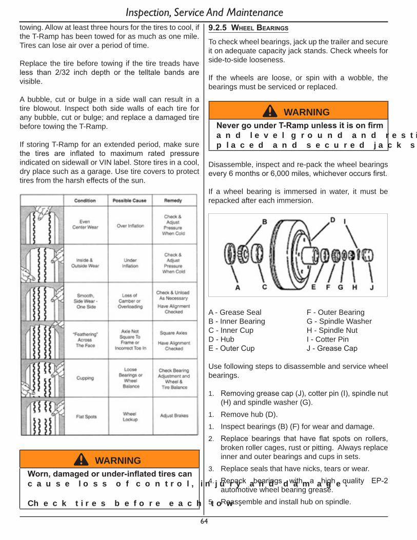
64
towing. Allow at least three hours for the tires to cool, if the T-Ramp has been towed for as much as one mile. Tires can lose air over a period of time.
Replace the tire before towing if the tire treads have less than 2/32 inch depth or the telltale bands are visible.
A bubble, cut or bulge in a side wall can result in a tire blowout. Inspect both side walls of each tire for any bubble, cut or bulge; and replace a damaged tire before towing the T-Ramp.
If storing T-Ramp for an extended period, make sure the tires are inflated to maximum rated pressure indicated on sidewall or VIN label. Store tires in a cool, dry place such as a garage. Use tire covers to protect tires from the harsh effects of the sun.
^ WARNINGWorn,damagedorunder-inflatedtirescanc a u s e l o s s o f c o n t r o l , i n j u r y a n d d a m a g e .
C h e c k t i r e s b e f o r e e a c h t o w .
9.2.5 wheel bearIngs
To check wheel bearings, jack up the trailer and secure it on adequate capacity jack stands. Check wheels for side-to-side looseness.
If the wheels are loose, or spin with a wobble, the bearings must be serviced or replaced.
^ WARNINGNevergounderT-Rampunlessitisonfirma n d l e v e l g r o u n d a n d r e s t i n g o n p r o p e r l y p l a c e d a n d s e c u r e d j a c k s t a n d s .
Disassemble, inspect and re-pack the wheel bearings every 6 months or 6,000 miles, whichever occurs first.
If a wheel bearing is immersed in water, it must be repacked after each immersion.
A - Grease Seal F - Outer BearingB - Inner Bearing G - Spindle WasherC - Inner Cup H - Spindle NutD - Hub I - Cotter PinE - Outer Cup J - Grease Cap
Use following steps to disassemble and service wheel bearings.
1. Removing grease cap (J), cotter pin (I), spindle nut (H) and spindle washer (G).
1. Remove hub (D).1. Inspect bearings (B) (F) for wear and damage.2. Replace bearings that have flat spots on rollers,
broken roller cages, rust or pitting. Always replace inner and outer bearings and cups in sets.
3. Replace seals that have nicks, tears or wear. 4. Repack bearings with a high quality EP-2
automotive wheel bearing grease.5. Reassemble and install hub on spindle.
Inspection, Service And Maintenance

65
6. Turn hub slowly by hand while tightening spindle nut until you can no longer turn hub by hand.
7. Loosen spindle nut just until you are able to turn it (spindle nut) by hand. Do not turn the hub while spindle nut is loose.
8. Install new cotter pin (I) through spindle nut and axle.
9. Check adjustment. Both hub and spindle nut should be able to move freely (spindle nut motion will be limited by cotter pin).
9.2.6 lubrICatIon
Coupler - Pump marine grade grease into zerk fitting until ball chamber is overfilled.
Gas Shock Ball & Sockets - Lubricate all with approved spray silicone.
Main Lock Pivot Points (A) - Lubricate with approved spray silicone.
Ramp Lock Pivot Points (B) - Lubricate with approved spray silicone.
Section Lock Pins - Lubricate with approved spray silicone.
Ramp/Trailer Wedges - Lubricate with approved spray silicone.
Inspection, Service And Maintenance
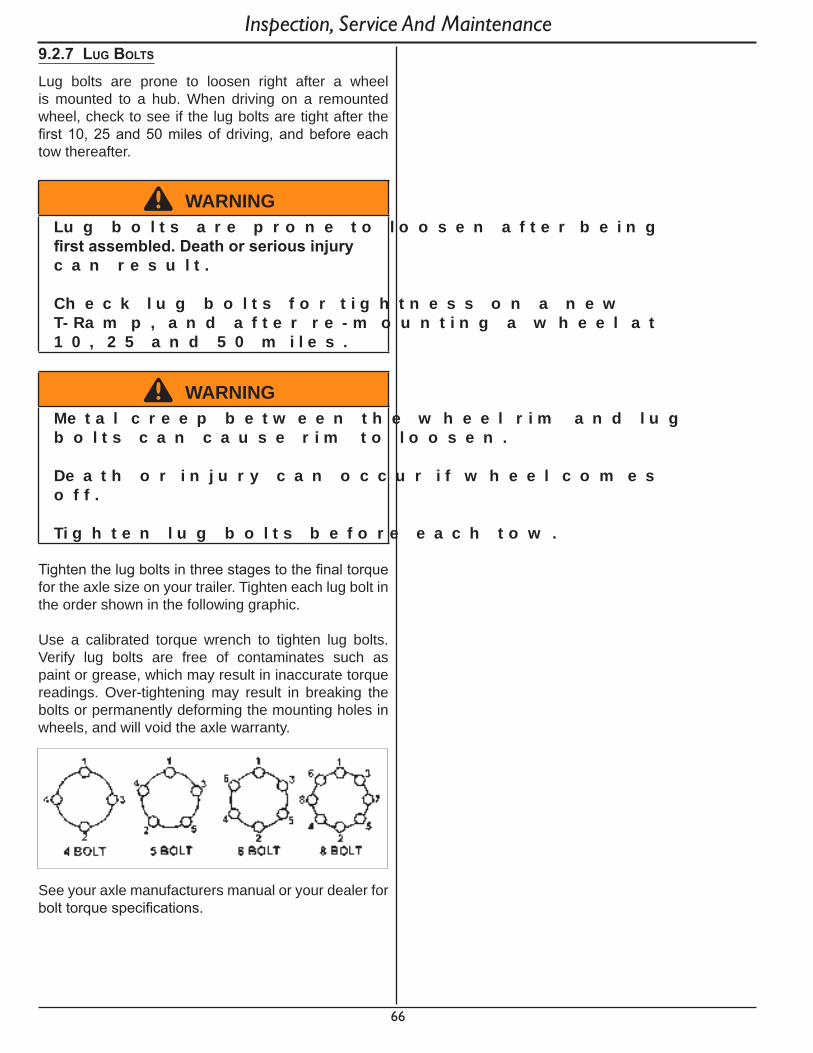
66
Inspection, Service And Maintenance9.2.7 lug bolts
Lug bolts are prone to loosen right after a wheel is mounted to a hub. When driving on a remounted wheel, check to see if the lug bolts are tight after the first 10, 25 and 50 miles of driving, and before each tow thereafter.
^ WARNINGL u g b o l t s a r e p r o n e t o l o o s e n a f t e r b e i n g firstassembled.Deathorseriousinjuryc a n r e s u l t .
C h e c k l u g b o l t s f o r t i g h t n e s s o n a n e w T - Ra m p , a n d a f t e r r e - m o u n t i n g a w h e e l a t 1 0 , 2 5 a n d 5 0 m i l e s .
^ WARNINGM e t a l c r e e p b e t w e e n t h e w h e e l r i m a n d l u g b o l t s c a n c a u s e r i m t o l o o s e n .
D e a t h o r i n j u r y c a n o c c u r i f w h e e l c o m e s o f f .
T i g h t e n l u g b o l t s b e f o r e e a c h t o w .
Tighten the lug bolts in three stages to the final torque for the axle size on your trailer. Tighten each lug bolt in the order shown in the following graphic.
Use a calibrated torque wrench to tighten lug bolts. Verify lug bolts are free of contaminates such as paint or grease, which may result in inaccurate torque readings. Over-tightening may result in breaking the bolts or permanently deforming the mounting holes in wheels, and will void the axle warranty.
See your axle manufacturers manual or your dealer for bolt torque specifications.
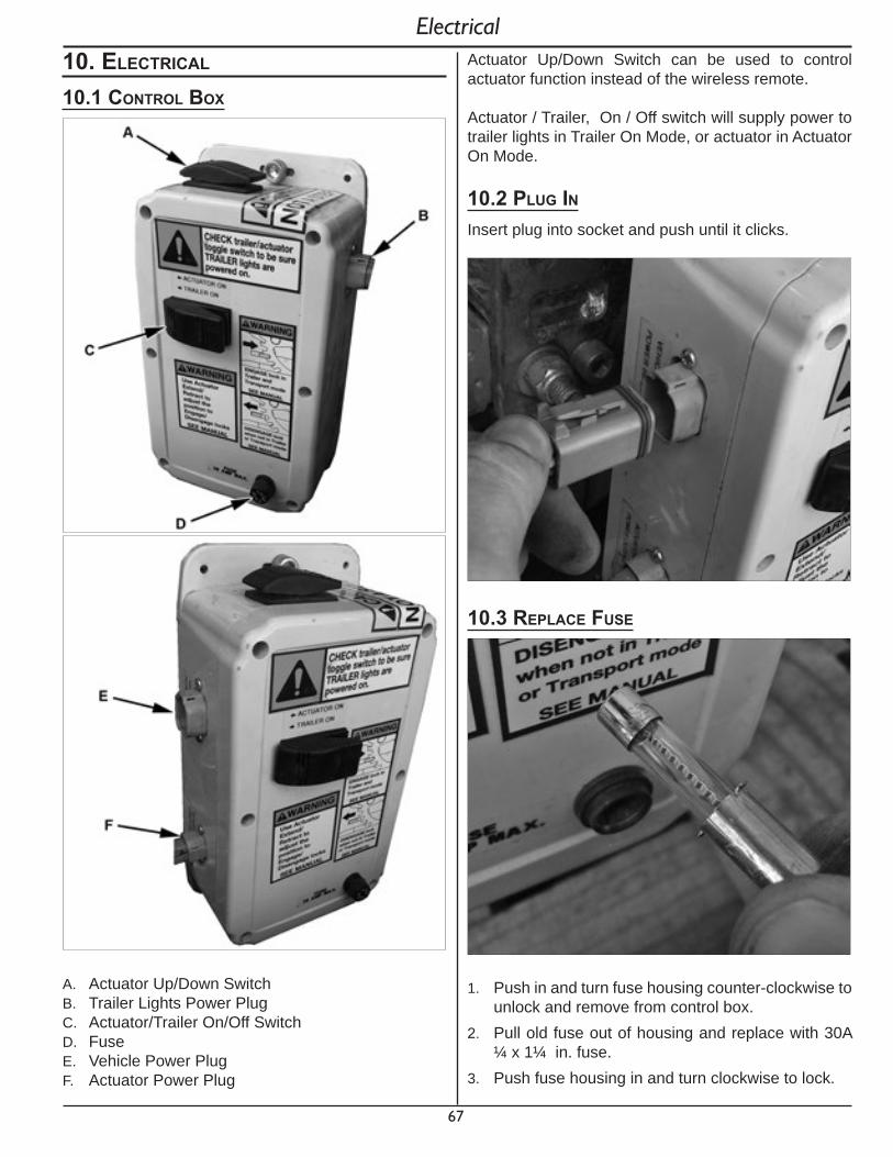
67
Electrical10. eleCtrICal
10.1 Control box
A. Actuator Up/Down SwitchB. Trailer Lights Power PlugC. Actuator/Trailer On/Off SwitchD. FuseE. Vehicle Power PlugF. Actuator Power Plug
Actuator Up/Down Switch can be used to control actuator function instead of the wireless remote.
Actuator / Trailer, On / Off switch will supply power to trailer lights in Trailer On Mode, or actuator in Actuator On Mode.
10.2 plug InInsert plug into socket and push until it clicks.
10.3 replaCe fuse
1. Push in and turn fuse housing counter-clockwise to unlock and remove from control box.
2. Pull old fuse out of housing and replace with 30A ¼ x 1¼ in. fuse.
3. Push fuse housing in and turn clockwise to lock.

68
Electrical10.4 wIreless remote
10.4.1 battery replaCement
1. Remove screws on back of remote and remove cover.
2. Replace battery with Lithium CR 2032 Battery3. Install back cover and tighten screws to seal the
back cover.
10.4.1 programmIng the remote
After battery replacement, wireless remote may need to be re-programmed to sync with the control box. Follow these steps to program your remote.1. Move Switch (A) to Trailer On position.
2. Wait 20 seconds to allow the processor to fully power down.
3. Press and HOLD the UP or DOWN button on the wireless remote.
4. While still holding the remote button, move Switch (A) to the Actuator On position.
5. When actuator activates and starts moving, immediately release the remote button. Be sure that the T-Ramp is safe to operate before continuing.

69
11. warranty
Please refer to your warranty agreement as issued at the time of purchase for warranty information.
Thank you for purchasing the Condor® T-RampTM.
Condor® is a registered trademark of Technical Components Development & Design, Inc.
Patent Numbers: 8,123,455; 9,010,795; 13/406,425; 61/984,362
Technical Components Development & Design, Inc.Condor® Products 210 W. Stephenie Drive Cortland, IL 60112
Phone: (815) 754-7418Fax: (815) 754-7419 Web Site: www.condor-lift.com
Warranty

70
12. aCCessorIes
The T-Ramp is prepared at the factory to accept several Condor® products**.
Installation instructions are provided with each product.
SC-2000
PS-1500
SC-3000 Trailer Adapter For SC-2000**
Accessories
TK-3000 Trailer Adapter For PS-1500**
** Some drilling may be required.