Embed Size (px)
Citation preview

BREN-TRONICS, INC. P: 631-499-5155 | F: 631-499-5504 www.bren-tronics.com 850013 Rev D
OPERATION MANUAL
BTC-70801 (PP-8498/U) NSN: 6130-01-495-2839 Copyright © Bren-Tronics, Inc. 2013

BREN-TRONICS, INC. 10 Brayton Court Commack, NY 11725 P: 631-499-5155 | F: 631-499-5504 www.bren-tronics.com
Page 2 of 28
BTC-70801 (PP-8498/U) SOLDIER PORTABLE CHARGER (SPC)
OPERATION MANUAL 850013 REV D
Data presented in this document is subject to change without notice
WARNING
HIGH VOLTAGES ARE PRESENT IN THE
OPERATION OF THIS EQUIPMENT
Avoid contact with AC supply voltage connections during installation, operation or maintenance of the battery charger.
CAUTION
ACID CONTAMINATES NICKEL-CADMIUM, LITHIUM-ION, LITHIUM-POLYMER and NICKEL-METAL HYDRIDE BATTERIES
Every effort must be made to keep Nickel-Cadmium, Lithium-Ion, Lithium
Polymer and Nickel-Metal Hydride batteries as far away as possible from Lead-Acid batteries because Lead-Acid batteries contain sulfuric acid. Do Not use
the same tools and materials, such as screwdrivers, wrenches, syringes, hydrometers, and gloves for both types of batteries. Any trace of acid or acid
fumes will permanently damage Nickel-Cadmium, Lithium-Ion, Lithium Polymer and Nickel-Metal Hydride batteries on contact.
WARNING
NO SMOKING IS PERMITTED NEAR THE CHARGING STATION Batteries can produce explosive gases during charging or discharge cycles. Never smoke or allow open flames near the charging station.
NOTICE TO PERSONS RECEIVING THIS DRAWING AND/OR TECHNICAL INFORMATION:
BREN-TRONICS, INC. claims proprietary rights in the material disclosed herein. This drawing and/or technical information is issued in confidence for information only and may not be reproduced or used to manufacture anything shown or referred to heron without direct permission from BREN-TRONICS, INC. to the user. This drawing and/or technical information is loaned for mutual assurance and is subject to recall by BREN-TRONICS INC. at any time.
This drawing and/or technical information
is the property of BREN-TRONICS, INC.

BREN-TRONICS, INC. 10 Brayton Court Commack, NY 11725 P: 631-499-5155 | F: 631-499-5504 www.bren-tronics.com
Page 3 of 28
BTC-70801 (PP-8498/U) SOLDIER PORTABLE CHARGER (SPC)
OPERATION MANUAL 850013 REV D
Data presented in this document is subject to change without notice
SPC Operation Manual
Table of Contents 1 INTRODUCTION ................................................................................................ 4
1-1 SCOPE ...................................................................................................... 4
1-2 TECHNICAL SPECIFICATIONS ............................................................... 5
1-3 ACCESSORIES ......................................................................................... 6
1-4 CHARGE CYCLE DESCRIPTION ........................................................... 10
1-5 SEQUENTIAL CHARGING CYCLE DESCRIPTION ............................... 11
1-6 MULTI-CHARGING CYCLE DESCRIPTION ........................................... 12
1-7 UPGRADING CHARGER SOFTWARE ................................................... 13
2 OPERATING PROCEDURES .......................................................................... 14
2-1 PANEL CONTROLS AND INDICATORS ................................................ 14
2-2 PRELIMINARY SETUP PROCEDURES ................................................. 17
2-3 CHARGING BATTERIES ........................................................................ 18
2-4 BATTERY CHARGER COVER LABEL ................................................... 19
2-5 SOLID RED LED TROUBLE SHOOTING ............................................... 20
2-6 FLASHING RED LED TROUBLE SHOOTING ........................................ 20
2-7 OPERATION IN EXTREME ENVIRONMENTAL CONDITIONS ............. 21
2-8 PREPARATION FOR MOVEMENT ......................................................... 21
2-9 BATTERY STATE-OF-CHARGE DISPLAYS .......................................... 22
2-10 BATTERY CAPACITY RETENTION ....................................................... 22
2-11 BATTERY STORAGE ............................................................................. 23
3 OPERATOR MAINTENANCE INSTRUCTIONS ............................................... 24
3-1 INTRODUCTION ..................................................................................... 24
3-2 CLEANING .............................................................................................. 24
3-3 INSPECTION ........................................................................................... 24
3-4 BASIC FUNCTIONAL TEST .................................................................... 25
3-5 SIMPLIFIED OPERATOR TROUBLESHOOTING PROCEDURES ........ 26
3-6 WARRANTY / REPAIR INFORMATION .................................................. 28
3-7 UPGRADE / UPDATE INFORMATION ................................................... 28

BREN-TRONICS, INC. 10 Brayton Court Commack, NY 11725 P: 631-499-5155 | F: 631-499-5504 www.bren-tronics.com
Page 4 of 28
BTC-70801 (PP-8498/U) SOLDIER PORTABLE CHARGER (SPC)
OPERATION MANUAL 850013 REV D
Data presented in this document is subject to change without notice
1 INTRODUCTION
1-1 SCOPE
The Soldier Portable Charger PP-8498/U (P/N BTC-70801) is a state-of-the-art, high performance lightweight portable battery charger designed for field deployment or shop usage. It provides fast reactivation of various rechargeable batteries. It is capable of sequentially charging up to eight batteries completely unattended.
The Soldier Portable Charger (SPC) is simple to use by design. Without any user intervention, the SPC typically charges up to eight batteries in approximately eight hours. Charge times are substantially less for partially discharged batteries. There are also batteries that will charge in less than two (2) hours. LED’s will indicate same. It automatically identifies the specific battery type and provides the appropriate charge profile. Based on the current operating environment, the SPC automatically customizes the charge profile to provide the quickest charge in a safe manner. The charge status for each of the eight batteries is conveyed to the user via three easy-to-understand panel mounted LED indicators (amber – CHARGE, green – READY and red – FAULT).
The SPC is universal by design. It can readily use either AC or DC input power – whichever is most convenient for the user. The universal AC input fully allows 90-260 VAC and 47-420 Hz operation without any adjustment or user intervention. Additionally, the DC input power permits a range of 22-28 VDC, standard on most military vehicles.
The SPC is adaptive by design. It is microprocessor controlled and is presently programmed to automatically charge over 50 different battery types as listed in the Table 1. With the appropriate battery adapter, however, it can be readily reprogrammed via RS232 software upgrade port in the field to charge a countless number of additional battery types and chemistries including: Nickel Metal Hydride, Nickel Cadmium, Lithium Ion, and Lithium Polymer.
The battery charger components are housed in a durable, non-conductive ABS equipment case, as shown in Figure 1. The assembled unit is watertight when the gasketed cover is securely latched and the pressure equalization valve on the front of the case (near the carrying handle) is closed. It is shipped with four AP-390/2590 adapters.

BREN-TRONICS, INC. 10 Brayton Court Commack, NY 11725 P: 631-499-5155 | F: 631-499-5504 www.bren-tronics.com
Page 5 of 28
BTC-70801 (PP-8498/U) SOLDIER PORTABLE CHARGER (SPC)
OPERATION MANUAL 850013 REV D
Data presented in this document is subject to change without notice
1-2 TECHNICAL SPECIFICATIONS
Dimensions………………..22.8 in. (579 mm) W x 14.6 in. (371 mm) D x 9.0 in. (229 mm) H
Weight……………………..27.5 lbs (12.5 kg) Power Requirements
AC operation………Automatic selection: 90V to 260V AC, single-phase, 47 to 420 Hz, 375 VA max, with 6.5 ft. (198 cm) detachable
three-wire power cord. (Power draw @125V AC = 3 Amps)
DC operation ………22-28 VDC, 15A; with optional 12 ft (366 cm) DC cable assembly. (Power draw @ 24 VDC = 12.5 AMPs) Charging Output Voltage... Automatically selected for each battery type Duty Cycle………………… Continuous Protective Features……… Resettable circuit breakers for AC (7A) and DC (20A)
power sources Operating Temp. Range….-4oF (-20oC) to +122oF (+50oC) Storage Temp. Range……-40oF (-40oC) to +158oF (+70oC) Loose Cargo Bounce…….. Meets requirements of MIL-STD-810E, Method 514.4,
Category 3 Case Material…………….. ABS (Acrylonitrile Butadiene Styrene) Case Color………………... Olive Drab #34088 per Fed-Std-595B (other colors
optional) Shipment………………….. No restrictions

BREN-TRONICS, INC. 10 Brayton Court Commack, NY 11725 P: 631-499-5155 | F: 631-499-5504 www.bren-tronics.com
Page 6 of 28
BTC-70801 (PP-8498/U) SOLDIER PORTABLE CHARGER (SPC)
OPERATION MANUAL 850013 REV D
Data presented in this document is subject to change without notice
1-3 ACCESSORIES
Table 1 shows the various batteries and appropriate adapter plates the SPC can charge as of the writing of this document.
Table 2 shows various power cables and other accessories.
Table 1 - Supported Batteries and Adapters
ADAPTER ADAPTER NSN BATTERY FEATURE TYPE BATTERY NSN
BTA-70360 6130-01-555-7818 BB-4600 --- NiCd 6140-13-113-0171
BTA-70394 5940-01-427-9247 BB-503A/U --- NiCd 6140-01-419-8193
BTA-70395 5940-01-427-9183 BB-326/U BB-516A/U
--- ---
NiMH NiCd
6140-01-533-7674 6140-01-419-8191
BTA-70396 5940-01-427-9278 BB-2847A/U BB-2847/U
--- ---
Li Ion Li Ion
6140-01-493-8092 6140-01-419-8194
BTA-70406 --- BB-586 --- NiCd 6140-01-084-1460
BTA-70406-3 --- BB-386 --- NiMH ---
BTA-70443 5940-01-467-8813 BB-2600/U BB-2600A/U
--- ---
Li Ion Li Ion
6140-01-467-5853 6140-01-490-4311
BTA-70492A 5940-01-513-5662 BT-70477 BT-70492 BT-70492A
--- --- ---
NiMH Li Ion Li Ion
6140-14-513-5369 6140-01-523-9840 6140-01-523-9840
BTA-70557 5940-01-467-5852 BB-557/U --- NiCd 6140-01-071-5070
BTA-70574 5940-01-483-6772 ICOM SI --- NiCd ---
BTA-70581 --- BT-70581xx M Li Ion 6140-01-534-3856
BTA-70581A 5940-01-544-3476 BT-70581xx M Li Ion 6140-01-534-3856
BTA-70582 --- ALI 124 ALI 142/BA-682A BA-682B BA-684ª
--- --- --- ---
NiCd Li Ion Li Ion Li Ion
--- 6140-14-328-2258 6140-14-561-1542 6140-14-529-5971
BTA-70582-1 --- ALI 142/BA-682A BA-682B BA-684ª
--- --- ---
Li Ion Li Ion Li Ion
6140-14-328-2258 6140-14-561-1542 6140-14-529-5971
BTA-70589 6130-01-564-8116 ALI 116 ALI 124 ALI 142/BA-682A ALI 143/BA-687A ALI 243 BA-684A BA-685A BA-682B ALI 147 ALI 247
--- --- --- --- --- --- --- --- --- ---
NiCd NiCd Li Ion Li Ion Li Ion Li Ion Li Ion Li Ion Li Ion Li Ion
--- ---
6140-14-328-2258 6140-14-530-0061 6140-14-553-4062 6140-14-529-5971 6140-14-529-5973 6140-14-561-1542
--- ---

BREN-TRONICS, INC. 10 Brayton Court Commack, NY 11725 P: 631-499-5155 | F: 631-499-5504 www.bren-tronics.com
Page 7 of 28
BTC-70801 (PP-8498/U) SOLDIER PORTABLE CHARGER (SPC)
OPERATION MANUAL 850013 REV D
Data presented in this document is subject to change without notice
BTA-70589A --- ALI 142/BA-682A ALI 143/BA-687A ALI 243 BA-684A BA-685A BA-682B ALI 147 ALI 247
--- --- --- --- --- --- --- ---
Li Ion Li Ion Li Ion Li Ion Li Ion Li Ion Li Ion Li Ion
6140-14-328-2258 6140-14-530-0061 6140-14-553-4062 6140-14-529-5971 6140-14-529-5973 6140-14-561-1542
--- ---
BTA-70598 --- BT-70598 --- Li Ion ---
BTA-70661 --- BT-70661 --- Li Ion ---
BTA-70680 SPR M Li Ion ---
BTA-70685 --- ALKABAT --- NiCd ---
BTA-70706-1 --- BB-2598 --- Li Ion ---
BTA-70715 5940-01-573-9693 BT-70593 BT-70715
M M
Li Ion Li Ion
--- ---
BTA-70721 6130-01-573-4962 BT-70721 --- Li Ion ---
BTA-70732 --- BT-70732 --- Li Ion ---
BTA-70737 --- BT-70737 M Li Ion ---
BTA-70740 --- BT-70740 M Li Ion ---
BTA-70763 6130-01-555-7821 BN-2250 --- NiCd 6140-13-116-5482
BTA-70774 5940-01-573-9679 Motorola – NNTN7032A NTN9816A NTN9815A
M --- ---
Li Ion NiCd NiCd
--- --- ---
BTA-70807 5940-01-493-6750 BB-2800/U --- Li Ion 6140-01-490-5372
BTA-70808 5940-01-493-6388 BB-2588/U BB-388/U
M ---
Li Ion NiMH
6140-01-493-7623 6140-01-490-4313
BTA-70810 5940-01-493-6751 THALES – MBITR BT-70716
M M
Li Ion Li Ion
--- ---
BTA-70811 5940-01-493-7622 AA CELLS --- NiMH ---
BTA-70812 5940-01-492-7238 BB-2557/U BB-557/U
--- ---
Li Ion NiCd
6140-01-490-5387 6140-01-071-5070
BTA-70817 --- D CELLS --- NiMH ---
BTA-70834 5940-01-501-3312 BB-2590/U BT-70791A BT-70791Bx BT-70791Cx BT-70791E BB-390B/U BT-70876 SAFT – BB-2590
--- --- --- --- --- --- --- ---
Li Ion Li Ion Li Ion Li Ion Li Ion NiMH Li Ion Li Ion
6140-01-490-4316 --- --- --- ---
6140-01-490-4317 --- ---
BTA-70838-7 6150-01-609-0353 BT-70838xx BT-70838-2/3xx BT-70838-1/3xx
M M M
Li Ion Li Ion Li Ion
--- --- ---
BTA-70851 --- Racal 931 --- NiCd ---
BTA-70852 --- PTR-349 --- NiCd ---
BTA-70853 --- Loral – RT1606 --- NiCd ---
BTA-70855 --- ATK –XM25 M Li Ion ---
BTA-70858 --- DRT 4453/4411 M Li Ion ---
BTA-70868 --- LI-145 LI-80 BT-70867
M M M
Li Ion Li Ion Li Ion
--- --- ---
BREN-TRONICS, INC. 10 Brayton Court Commack, NY 11725 P: 631-499-5155 | F: 631-499-5504 www.bren-tronics.com
Page 8 of 28
BTC-70801 (PP-8498/U) SOLDIER PORTABLE CHARGER (SPC)
OPERATION MANUAL 850013 REV D
Data presented in this document is subject to change without notice
BT-70868 M Li Ion ---
BTA-70872 --- BB-NM10 --- NiCd ---
BTA-70874 --- RIFLEMAN LIBERTY
M ---
Li Ion Li Ion
--- ---
BTA-70903 --- BB-2590/U (See Note 6)
BT-70791A (See Note 6)
BT-70791Bx (See Note 6)
BT-70791Cx (See Note 6)
BT-70791E (See Note 6) BB-390B/U BT-70876 SAFT – BB-2590 Ultralife – UBI-2590
--- --- --- --- --- --- --- --- ---
Li Ion Li Ion Li Ion Li Ion Li Ion NiMH Li Ion Li Ion Li Ion
6140-01-490-4316 ---
--- --- ---
6140-01-490-4317 --- --- ---
BTA-70910 --- CONFORMAL M Li Ion ---
NOTES:
1) The ICOM Adapter (J-6556/P) is not compatible with this charger and can only be used in the PP-8444A/U.
2) Adapter (BTA-70480/3) is not compatible with this charger. 3) These Adapters are supported by the charger Revision H software. 4) This list was complete at the date of publication. Additional Adapters may be
available, but may require additional software. 5) In “FEATURE” section - M = Multi Chargeable. 6) Adapter (BTA-70903) will charge the Bren-Tronics’ BB-2590 batteries to
16.8V. Do not install batteries charged to 16.8V in equipment not rated for 16.8V operation or equipment may be damaged.

BREN-TRONICS, INC. 10 Brayton Court Commack, NY 11725 P: 631-499-5155 | F: 631-499-5504 www.bren-tronics.com
Page 9 of 28
BTC-70801 (PP-8498/U) SOLDIER PORTABLE CHARGER (SPC)
OPERATION MANUAL 850013 REV D
Data presented in this document is subject to change without notice
Table 2 - Power Cables and Other Accessories
DESCRIPTION PART NUMBER NSN
DC POWER CABLE (Ring Lugs) BTA-70844-24 6150-01-564-8578
DC POWER CABLE (Alligator Clips) BTA-70844-24AL ---
DC HUMMER CABLE BTA-70835 (J-6362A/U) 5940-01-501-6714
DC CABLE SPLITTER BTA-70816 (CX-13560/G) 5995-01-505-7883
BB-390/2590 SELF DISCHARGER BTF-70791 (PP-8497/U) 6130-01-490-4310
Note: These accessories are optional.
Figure 1-3.1 BTA-70844-24
Figure 1-3.2 BTA-70844-24AL
Figure 1-3.3 BTA-70835 (J-6362A/U) Figure 1-3.4 BTA-70816 (CX-13560/G)
For use with DC Hummer Cable
Figure 1-3.5 BTF-70791 (PP-8497/U)
BREN-TRONICS, INC. 10 Brayton Court Commack, NY 11725 P: 631-499-5155 | F: 631-499-5504 www.bren-tronics.com
Page 10 of 28
BTC-70801 (PP-8498/U) SOLDIER PORTABLE CHARGER (SPC)
OPERATION MANUAL 850013 REV D
Data presented in this document is subject to change without notice
1-4 CHARGE CYCLE DESCRIPTION
Each of the battery types that are capable of being charged by the SPC is connected to the charger via their respective battery adapter (plate or cable). Each adapter can charge two batteries simultaneously. The appropriate battery adapter is installed on the control panel and serves as the electrical interface between the batteries being charged and the charger circuits. The battery charger control circuits constantly monitor the following battery conditions during the charge cycle, as appropriate, to ensure that the battery is properly being charged:
a. Temperature (T) b. Voltage (V) c. Current (I) d. Time (t) e. Voltage change (ΔV) f. Temperature rate of change (ΔT/Δt)
The charger operation during a typical charge sequence is automatic and the battery charge status is displayed to the user by the panel LED indicators as follows:
a. Detection - The charger tries to detect a battery in an adapter. The CHARGE LED (amber) blinks slowly during this process.
b. Pre-charge – The charger brings the battery voltage up to a safe level before the rapid charge process begins. This step may take several minutes for a very discharged battery. The CHARGE LED (amber) blinks rapidly during this process.
c. Fast Charge – A timed fast charge cycle brings the battery to approximately 90% of full charge capacity. The CHARGE LED (amber) is lit solid during this process.
d. Ready – The fast charge cycle is complete. The Battery may be removed and used at this time. The READY LED (green) is lit steadily at this time.
e. Trickle / Top-off – When fast charge is complete, the charger will top off of the battery to 100%. Each battery is charged for five minutes at a time (10 minutes for dual section batteries – i.e. BB-390B/U, BB-2590/U). For Lithium Ion and Lithium Polymer batteries the top-off cycle will stop after the battery is 100% charged. For all other types, the Trickle / Top-off cycle is repeated indefinitely to keep the battery at 100% charge. Leaving the battery on the charger will not harm the battery. The battery may be removed and used at this time. The READY LED (green) blinks during this process.
The Battery may be removed and used at anytime during the charge cycle without damage to the charger or battery. The state-of-charge indicator (SOC) will display the battery condition.
NOTE After removing a battery from the charger, wait for the corresponding battery status LED’s to turn off before installing a new battery.

BREN-TRONICS, INC. 10 Brayton Court Commack, NY 11725 P: 631-499-5155 | F: 631-499-5504 www.bren-tronics.com
Page 11 of 28
BTC-70801 (PP-8498/U) SOLDIER PORTABLE CHARGER (SPC)
OPERATION MANUAL 850013 REV D
Data presented in this document is subject to change without notice
1-5 SEQUENTIAL CHARGING CYCLE DESCRIPTION
The SPC is a dual-channel sequential charger. It automatically charges up to eight batteries in approximately eight hours – depending on the battery type and state-of-charge.
Two independent charging channels, designated A and B, can charge one battery at a time. Upon charge completion of the first battery, each channel sequentially charges up to three additional batteries that are waiting in queue. Sequencing to the other three Ports is performed completely automatic and requires no intervention by the user. While the four batteries charged by the A channel are located at either the rear or left side of each adapter Port (depending on the adapter type), the four batteries charged by the B channel are located at either the front or right side of each adapter Port. This is readily seen in Figure 1-5.1.
Figure 1-5.1 - SPC Typical Configuration
During the sequencing process, the channel spends only as much time as is necessary to charge each battery to greater than 90% capacity. A partially charged battery will charge quicker than a totally discharged battery. It then sequences, in numerical order (Port 1 – Port 2 – Port 3 – Port 4 – Port 1 – Port 2, etc.), to the next battery in queue. As the channel sequences through the four Ports and comes to a battery that has already been charged, it will attempt to Trickle or Top-off that battery (if necessary) for approximately 5 minutes (10 minutes for dual section batteries like the BB-390 and BB-2590) and then continue onto the next Port.
This means batteries added later may charge first, depending on their position on the charger. If certain batteries must be charged first, then this must be taken in to account. When the charger moves to a position it will charge or top off the battery at that position, as necessary. This allows batteries to be added or removed at anytime. The charger automatically keeps track of the current state of each Port.

BREN-TRONICS, INC. 10 Brayton Court Commack, NY 11725 P: 631-499-5155 | F: 631-499-5504 www.bren-tronics.com
Page 12 of 28
BTC-70801 (PP-8498/U) SOLDIER PORTABLE CHARGER (SPC)
OPERATION MANUAL 850013 REV D
Data presented in this document is subject to change without notice
1-6 MULTI-CHARGING CYCLE DESCRIPTION
Along with sequential charging, the SPC charges can also charge up to 8 batteries at once.
The charger will automatically identify batteries than can be multi-charged; no special action is required by the user. The new feature charges the batteries in parallel. Eight standard CSEL batteries can be charged in less than 4 hours. Significant time savings will be noticed for smaller groups of batteries.
Multi-Charging does not require any special setup. Two different adapters can be used at the same time. The charger will automatically detect which batteries can be charged as a group.
The Multi-Charging process works as follows. The SPC has two high power charging channels. The unique characteristics of Lithium Ion batteries allow the charger to charge the batteries in parallel. This allows the channel to use maximum power for a longer time. This can produce a large savings in time, charging four MBITR batteries simultaneously takes four hours compare to three hours for just one. The charging sequence is similar to normal battery charging with the exception that if a multi-chargeable battery is found the charger will pre-qualify it (status indicators flashing amber) and look for more. Incompatible batteries will be skipped, until later. When the charger can find no more batteries it will start the rapid charge phase. The status indicators will now be solid amber. As each battery finishes, the status indicators will turn green one at a time as each battery is completed. A battery with a green indicator can be removed and used as a normally charged battery. After the charger has completed the group, it will continue charging other single or grouped batteries as it finds them.
To get the most time savings from Multi-Charging, a few rules apply. While the status indicators are yellow, removing a charging battery will restart the entire group. This is normal. If batteries are added after the LEDs have turned amber, they will not be added to the group. If the LEDs are still flashing amber then batteries can still be added to the group. This is true even if the charger has passed the position, it will go back until it has collected all the batteries to be charged. If there is a large quantity of batteries to be charged, grouping the batteries will save charging time. Group them on channel A or on channel B since the channels operate independently. Batteries that have similar SOC indications should be grouped together. This prevents the almost fully charged batteries from having to wait for a fully discharged one to catch up. Some batteries are available in different capacities yet still use the same adapters. Remember that parallel charging a group of batteries is always faster than charging them one at a time. (Note: Falcon II and Falcon III batteries, although similar, will not be grouped together for a parallel charge.)

BREN-TRONICS, INC. 10 Brayton Court Commack, NY 11725 P: 631-499-5155 | F: 631-499-5504 www.bren-tronics.com
Page 13 of 28
BTC-70801 (PP-8498/U) SOLDIER PORTABLE CHARGER (SPC)
OPERATION MANUAL 850013 REV D
Data presented in this document is subject to change without notice
1-7 UPGRADING CHARGER SOFTWARE
The software in the charger is readily field upgradeable. By loading new software into the charger, it is possible to alter its operation and add or change the charging profiles for the batteries. Loading new software into the charge is accomplished via the use of a standard RS232 interface of a personal computer (PC). Utilizing special software running on the PC in conjunction with the boot program resident within the charger, a two-way communication link is established and the revised operational parameters and battery charge profiles can be loaded into the charger. Specific instructions for upgrading the charger software are provided with the software upgrades.

BREN-TRONICS, INC. 10 Brayton Court Commack, NY 11725 P: 631-499-5155 | F: 631-499-5504 www.bren-tronics.com
Page 14 of 28
BTC-70801 (PP-8498/U) SOLDIER PORTABLE CHARGER (SPC)
OPERATION MANUAL 850013 REV D
Data presented in this document is subject to change without notice
2 OPERATING PROCEDURES
2-1 PANEL CONTROLS AND INDICATORS
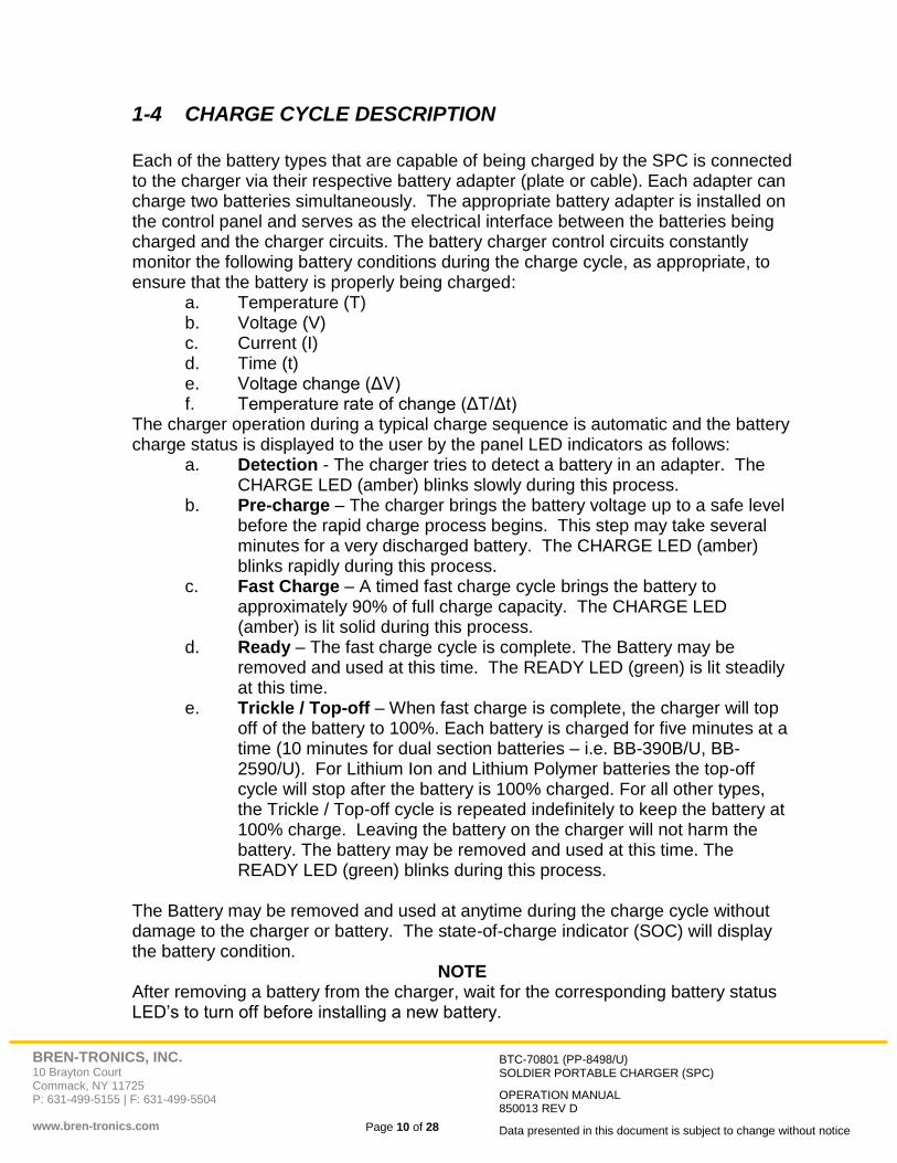
Battery charger panel components are described below and shown in Figure 2-1. Item Function
AC ON/OFF Power Switch………Turns battery charger AC supply on or off.
AC CIRCUIT BREAKER…………Turns power to the charger off in an overload condition. Remove the overload condition and push to reset.
POWER ON INDICATOR LED….The Power ON Indicator LED (Green) lights when the charger has sufficient power from either AC or DC.
LOW VEH POWER LED…………The Low Vehicle power indicator (Red) lights when external DC power is too low to charge batteries. The charger will stop charging batteries until sufficient power is available from the DC source.
TEMP FAULT LED……………….The Temperature Fault indicator (Amber) lights when charger temperature is too high 122 oF (50oC) or too low -4 oF (-20 oC). The charger will stop charging batteries.
DC ON/OFF Power Switch………Turns battery charger DC supply on or off. If both AC and DC power are connected and both power switches are on, then DC Power will be used by the charger.
DC CIRCUIT BREAKER…………Turns power to the charger off in an overload condition. Remove the overload condition and push to reset.
CHARGE LED…………………… The Amber LED lights steady while the associated battery is being fast-charged. A slow blinking indication means the charger is trying to find a battery at the select position. A fast blinking indication means the charger is precondition the battery before charging it.
READY LED………………………The Green LED indicates the associated battery is fully charged and ready to be removed for use. Steady light means the battery has completed fast charge. A blinking indication means the battery is being topped off.
FAULT LED…………………….....If the Red LED lights steady the associated battery, or adapter plate, is defective or will not accept charge. A blinking indication means the

BREN-TRONICS, INC. 10 Brayton Court Commack, NY 11725 P: 631-499-5155 | F: 631-499-5504 www.bren-tronics.com
Page 15 of 28
BTC-70801 (PP-8498/U) SOLDIER PORTABLE CHARGER (SPC)
OPERATION MANUAL 850013 REV D
Data presented in this document is subject to change without notice
battery’s temperature sensor or communication connection is not making contact with the adapter.
BATTERY ADAPTER PORT…….Provides interface connection for battery adapters.
AC INPUT Connector…………….Input connection for AC cable assembly. (Provided)
DC INPUT Connector…………….Input connection for DC cable assembly. (Optional)
BREN-TRONICS, INC. 10 Brayton Court Commack, NY 11725 P: 631-499-5155 | F: 631-499-5504 www.bren-tronics.com
Page 16 of 28
BTC-70801 (PP-8498/U) SOLDIER PORTABLE CHARGER (SPC)
OPERATION MANUAL 850013 REV D
Data presented in this document is subject to change without notice
Fig
ure
2-1
SP
C F
ron
t P
an
el
Co
mp
on
en
ts

BREN-TRONICS, INC. 10 Brayton Court Commack, NY 11725 P: 631-499-5155 | F: 631-499-5504 www.bren-tronics.com
Page 17 of 28
BTC-70801 (PP-8498/U) SOLDIER PORTABLE CHARGER (SPC)
OPERATION MANUAL 850013 REV D
Data presented in this document is subject to change without notice
2-2 PRELIMINARY SETUP PROCEDURES
Step 1. Place the unit on the work surface. Unscrew the pressure equalization
valve (near the carrying handle) in a counterclockwise direction about two full turns. Unfasten latches and open cover.
Step 2. Set AC and DC power ON-OFF switches, to OFF position.
Step 3. The Cover may be removed by removing both hinge pins with pliers.
Step 4. For AC operation: Connect AC power cord from AC INPUT connector to power source and set AC power ON-OFF switch to ON position. Observe that POWER ON LED lights, fan operates, and all LED status indicators blink in order (amber ,green, then red) briefly when power is first applied.
Step 5. For DC operation: Connect DC cable from 24 VOLT DC INPUT connector to DC power source (via NATO slave receptacle found in most military vehicles) and set DC power ON-OFF switch ON position. Observe that POWER ON LED lights, fan operates, and all LED status indicators blink in order (amber ,green, then red) briefly when power is first applied. Note that if both AC and DC power are connected that DC power will be used if the DC power switch is on.
Step 6. Observe that only the POWER ON LED is lit.
Step 7. Install appropriate battery adapter(s) on panel for battery types to be charged. Install the Adapter(s) by placing the back of the adapter into the rear retainer and rotating the adapter down until the front retainer clicks over it. For 18-pin cable type adapters plug the adapter in toward the right side. Note the alignment of the pins. The connector can only plug in one way. Do not force it. Be sure that battery adapter and connector are fully seated. All battery adapters are interchangeable, only the battery connections are different.
Step 8. Observe, after a short delay, the amber CHARGE LED’s blink for several seconds at each installed adapter. This shows battery charger circuits are initialized to the selected battery adapter and are ready to accept a battery (or batteries) for charging. If all of the Indicators for a channel light at the same time, the Adapter could not be recognized or the adapter is damaged. Insure it is seated correctly.
BREN-TRONICS, INC. 10 Brayton Court Commack, NY 11725 P: 631-499-5155 | F: 631-499-5504 www.bren-tronics.com
Page 18 of 28
BTC-70801 (PP-8498/U) SOLDIER PORTABLE CHARGER (SPC)
OPERATION MANUAL 850013 REV D
Data presented in this document is subject to change without notice
2-3 CHARGING BATTERIES
Step 1. With the appropriate battery adapter installed, insert the first battery to be
charged in the Port-1 Channel-A battery location. Insure the battery is fully seated into the adapter. Observe that CHARGE LED (amber) for the corresponding location is lit or blinking rapidly. The CHARGE LED for the B battery location will continue to blink if it is searching for a battery on that channel. If the FAULT LED (red) is lit, the battery or adapter may be defective. Check by removing battery and adapter. Then reinstall adapter and battery. If the FAULT LED again lights, go to the Trouble Shooting section of this Guide.
Step 2. Install the next battery into the Port-1 Channel-B battery location.
Step 3. Install the rest of the batteries. The indicators for these batteries will not light until the charger has finished the batteries in the preceding Port locations.
Step 4. After fast charging is complete, the CHARGE LED extinguishes and the READY LED is lit. After the charger cycles through the batteries, it will top-off batteries that have completed fast charge. The battery is slow-charged to full capacity, as indicated by the blinking READY LED (green). The battery is charged for five minutes at a time (10 minutes for dual section batteries) then the charger will move on to the next battery. For Lithium type batteries, the cycle will stop after the battery is 100% charged. For other types the cycle is repeated indefinitely to keep the battery at 100% charge. As long as the READY LED is lit (blinking or solid) the battery may be removed and returned to service and another battery may be installed for charging.
NOTE
BB-390A/U and BB-390B/U batteries include two independent 12-volt sections. A relay "clicking" may be heard from the battery adapter when battery sections are switched. Other types of adapters may also contain relays and click intermittently during normal operation.
NOTE
Battery charger power may be left ON while batteries and/or adapters are removed or replaced. Batteries may be left in the charge for long periods of time without damaging the batteries or charger.
CAUTION
To avoid damage to the adapter or SPC front panel connectors, always remove the adapter by grasping the front section finger-grips firmly with one hand while moving the front retainer back with the other. Lift the front of the adapter straight up from the panel. DO NOT attempt to remove the adapter by pulling upward from the rear.

BREN-TRONICS, INC. 10 Brayton Court Commack, NY 11725 P: 631-499-5155 | F: 631-499-5504 www.bren-tronics.com
Page 19 of 28
BTC-70801 (PP-8498/U) SOLDIER PORTABLE CHARGER (SPC)
OPERATION MANUAL 850013 REV D
Data presented in this document is subject to change without notice
2-4 BATTERY CHARGER COVER LABEL
Shown below are the instructions contained on the "SHORT FORM - OPERATING PROCEDURE" label, attached inside the SPC cover.
LED INDICATIONS FOR EACH BATTERY S = STEADY, F = FLASHING, RF = RAPID FLASHING
AMBER GREEN RED MEANING REMARKS
F F F Charger start up. All LED appear momentarily when charger is turned ON.
Power ON, No battery present or awaiting charge cycle. Possible bad battery if all charging is complete!
Install Battery into adapter or wait for full charge cycle. Bad battery?; hold for later screening, check web site.
F Power ON, adapter present, no battery
present in any adapter. Install battery(s) on to adapter or turn off charger.
RF Charge pre-qualification. Battery pre-charge check.
S Battery is fast charging. Can fast charge two batteries at one time.
F Battery is trickle charging.
Battery is ready to use! Remove when ready.
S
Fast charging is complete. Awaiting removal or another trickle cycle.
Battery is charged & ready to use! Remove when ready.
S Faulty battery. Remove & do not use! Consult SOP. Note position in charger & adapter, Problem repeated? Change adapter.
S S S Unknown adapter. Software revision required; Check web site for info.
S F Charging at slower rate due to damaged or dirty thermal pins/contacts.(*)
Clean battery thermal contacts on battery. Check adapter thermal pins; Repair or replace if missing.(*)
F or S F Charge complete at this location, but Thermal contacts caused longer charge times.(*)
Battery is good to go… clean battery thermal contacts & check adapter thermal pins; fix or replace.(*)
NOTE * BB-557/U will flash red while charging since there is no thermal contact. This is
normal.
For further info on the Army's rechargeable program visit the CECOM Power Sources Center of Excellence website at:
http://battery.army.mil
BREN-TRONICS, INC. 10 Brayton Court Commack, NY 11725 P: 631-499-5155 | F: 631-499-5504 www.bren-tronics.com
Page 20 of 28
BTC-70801 (PP-8498/U) SOLDIER PORTABLE CHARGER (SPC)
OPERATION MANUAL 850013 REV D
Data presented in this document is subject to change without notice
2-5 SOLID RED LED TROUBLE SHOOTING
1. Remove battery and inspect all contacts. Clean if nessasary. Then, reinstall at same location for another charge cycle. Note battery and adapter location for later review.
2. If charge indications go "red" again at the same location remove battery and do the following:
a. If the battery was in storage see para 2-11.
b. Check battery: older than 3 yrs? Maybe ready for disposal. Discharge & recharge, IF RED AGAIN?
c. Check warranty instructions on battery. If not covered or no instructions, dispose of.
d. Note success/failure of future battery charges at this location. More "RED" lights? Change adapter.
2-6 FLASHING RED LED TROUBLE SHOOTING
1. This condition is telling you that some of the battery contacts are not connecting to the charger.
a. For BB-390B/U thermal contacts are not making contact with the charger.
b. For BB-2590/U and other batteries the communication pin(s) are not making contact with the charger.
2. To minimize this issue before you first start using the charger: Ensure….
a. The contacts are clean on the battery. b. Adapter thermal pins are in place and retain their spring action: Check
by pushing down the pins and releasing.
3. You can still charge batteries with thermal/communication pins missing or damaged, it will just take longer, and may not fully charge in one cycle.
4. If flashing "red" condition after this check, mark location of condition and battery affected.
a. You can pull batteries and clean thermal contacts on the battery. b. Check adapters again. Mark for future review, if a continuing problem
at this location: change adapter.

BREN-TRONICS, INC. 10 Brayton Court Commack, NY 11725 P: 631-499-5155 | F: 631-499-5504 www.bren-tronics.com
Page 21 of 28
BTC-70801 (PP-8498/U) SOLDIER PORTABLE CHARGER (SPC)
OPERATION MANUAL 850013 REV D
Data presented in this document is subject to change without notice
2-7 OPERATION IN EXTREME ENVIRONMENTAL CONDITIONS
Observe these precautions when the SPC is operated in areas where severe climatic conditions may exist:
a. Operation in Arctic Climates. The battery charger is designed to function
in temperatures extremes as low as -4F (-20C.). The following precautions should be observed:
(1) Handle equipment carefully. The plastic components may become more brittle.
(2) Keep equipment clean and dry.
(3) Prevent ice from forming on the SPC and batteries. Ice formations may prevent proper electrical connections. Melting ice may cause water to enter the charger.
b. Operation in Desert Climates. The charger is designed to operate in
temperature extremes as high as 122F (50C) and the dryness associated with a desert environment. Sand and dust accumulation on and in the charger may cause poor electrical connections and reduce the cooling effectiveness of the charger. Follow proper cleaning and maintenance guidelines to assure proper operation. When not in use, be sure that cover is fully latched and pressure relief valve is fully closed (in a clockwise direction).
c. Operation in Salt Spray. Keep equipment clean and dry at all times and immediately wipe salt spray from exposed surfaces, cables and connectors. When not in use, be sure that cover is fully latched and pressure relief valve is fully closed (in a clockwise direction).
NOTES
Battery charge acceptance varies with ambient temperature conditions. At
temperatures lower than 32F (0C) or higher than 104F (40C) it may be necessary to initiate two complete charging cycles to secure a fully charged battery.
2-8 PREPARATION FOR MOVEMENT
a. Set both AC and DC POWER switches to OFF.
b. Remove any installed batteries.
c. Disconnect and coil AC power cable and retain with integral Velcro strip.
d. Remove the DC Power cable and pack separately.
e. Replace SPC cover if it was removed by reinstalling the hinge pins.
f. Close cover and secure with latches.
g. Close pressure equalization valve on front of unit by turning fully clockwise.

BREN-TRONICS, INC. 10 Brayton Court Commack, NY 11725 P: 631-499-5155 | F: 631-499-5504 www.bren-tronics.com
Page 22 of 28
BTC-70801 (PP-8498/U) SOLDIER PORTABLE CHARGER (SPC)
OPERATION MANUAL 850013 REV D
Data presented in this document is subject to change without notice
2-9 BATTERY STATE-OF-CHARGE DISPLAYS
Batteries equipped with state-of-charge (SOC) displays indicate battery charge status on a five-segment LCD bar graph readout. The number of LCD segments activated corresponds to the battery state-of-charge as follows:
Segments State-of-Charge 0 0% (fully discharged) 1 1 to 20% 2 21 to 40% 3 41 to 60% 4 61 to 80% 5 81 to 100% (fully charged)
NOTE
The BB-390A/U, BB-390B/U and BB-2590/U batteries have two SOC indicators. Each SOC indicator provides state-of-charge indication for each of the two 12V sections. Both SOC’s must display 100% for the battery to be fully charged.
2-10 BATTERY CAPACITY RETENTION
As shown in the adjoining graph, fully charged batteries that are stored lose a portion of their charge due to battery the chemistry. This is normal and should not be interpreted as battery failure. Storage at higher temperatures increases capacity losses while storage at lower temperature decreases capacity loses. The graph shows that Nickel based batteries like the BB-390B/U lose over 30% charge/month (1%/day) on the shelf waiting to be used. The BB-2590/U (a Li-Ion based battery) only loses less than 10% a month on the shelf.
BREN-TRONICS, INC. 10 Brayton Court Commack, NY 11725 P: 631-499-5155 | F: 631-499-5504 www.bren-tronics.com
Page 23 of 28
BTC-70801 (PP-8498/U) SOLDIER PORTABLE CHARGER (SPC)
OPERATION MANUAL 850013 REV D
Data presented in this document is subject to change without notice
2-11 BATTERY STORAGE
Nickel based batteries may require one or more charge/discharge cycles after a long period of storage. They may not charge fully on the first charge cycle. Repeat the charge if necessary. If the battery does not fully charge after three cycles it may no longer be serviceable. Lithium based batteries must be charged yearly if held in storage. Long term storage of fully discharged Lithium based batteries can permanently damage the battery. They do not require charge/discharge cycling after storage. If the battery does not charge (no SOC Bars), place it back on the charger for an additional charge cycle. It is not necessary to discharge it first. If the battery does not fully charge it may no longer be serviceable.
BREN-TRONICS, INC. 10 Brayton Court Commack, NY 11725 P: 631-499-5155 | F: 631-499-5504 www.bren-tronics.com
Page 24 of 28
BTC-70801 (PP-8498/U) SOLDIER PORTABLE CHARGER (SPC)
OPERATION MANUAL 850013 REV D
Data presented in this document is subject to change without notice
3 OPERATOR MAINTENANCE INSTRUCTIONS
3-1 INTRODUCTION
Periodic maintenance, inspection and cleaning will help insure the SPC is kept at full readiness.
3-2 CLEANING
1. Brush loose dirt and dust from the charger. Low-pressure air may be used to remove heavy dust from the case, connectors and power switches. Avoid blowing dust into the unit. Low-pressure air may be blown into the left and right air vents at the edge of the control panel to help remove internal dust.
2. Wipe surfaces with a damp (not wet) rag. Non-solvent cleaners maybe used (Windex™, Fantastik™, Formula 409™). Do not spray or drip water or cleaners onto the panel or into the connectors.
3. The flush mounted adapter connectors may be cleaned with electronic grade spray cleaner. Allow the cleaner to dry before installing the adapters or applying power to the charger.
4. The connections on the Adapters may be cleaned with electronic grade spray cleaner or isopropyl alcohol. Insure the Adapters are dry before using them.
3-3 INSPECTION
1. Inspect case for cracks and other damage.
2. Insure the lid gasket is in place.
3. Insure the Hinge Pins are fully inserted.
4. Insure the lid closes and can be properly latched.
5. Insure all Screws are in place and are not loose.
6. Inspect the panel and connectors for damage.
7. Inspect all adapters for excessive wear and damage.
a. Inspect charger connector for bent or corroded pins.
b. Inspect battery connector pins for damage or corrosion.
c. Insure all spring pins are not bent and move freely.
d. Note that spring pins can be removed and replaced.
8. Inspect power cords for damage.
9. Insure power switches move freely.
10. Insure the pressure equalization valve, located near the carrying handle is snugly tightened.

BREN-TRONICS, INC. 10 Brayton Court Commack, NY 11725 P: 631-499-5155 | F: 631-499-5504 www.bren-tronics.com
Page 25 of 28
BTC-70801 (PP-8498/U) SOLDIER PORTABLE CHARGER (SPC)
OPERATION MANUAL 850013 REV D
Data presented in this document is subject to change without notice
3-4 BASIC FUNCTIONAL TEST
1. Turn off all power switches, and remove all adapters.
2. Connect the SPC to AC power.
3. Turn On the AC power switch.
4. The front panel LED’s should light in sequence. Amber, then Green, then Red. Insure all LED’s light.
5. Insure the POWER-ON LED is lit and that all other indicators are off.
6. Place an Adapter into each of the four ports.
7. Verify that the CHARGE LED blinks for several seconds at each position, then moves to the next port.
8. Place a battery in Port 1 Channel A. Insure that the CHARGE LED blinks rapidly or turns on solid.
9. Repeat above step for all other ports and channels.
10. Turn off the AC power switch and disconnect AC Power.
11. Connect the SPC to DC Power.
12. Turn On the DC power switch.
13. The front panel LED’s should light in sequence. Amber, then Green, then Red. Insure all LED’s light.
14. End of Test.

BREN-TRONICS, INC. 10 Brayton Court Commack, NY 11725 P: 631-499-5155 | F: 631-499-5504 www.bren-tronics.com
Page 26 of 28
BTC-70801 (PP-8498/U) SOLDIER PORTABLE CHARGER (SPC)
OPERATION MANUAL 850013 REV D
Data presented in this document is subject to change without notice
3-5 SIMPLIFIED OPERATOR TROUBLESHOOTING PROCEDURES
ITEM MALFUNCTION POSSIBLE CORRECTIVE ACTION
1 POWER ON LED is not lit during AC operation.
1) Inspect Power Cord and AC Switch. 2) Reset AC circuit Breaker.
2 POWER ON LED is not lit during DC operation.
1) Inspect Power Cord and DC Switch. 2) Reset DC circuit Breaker.
3 All LED’s light and stay lit after the charger is turned on.
1) The unit has lost its program. a) Re-program the unit. b) The unit requires repair. Call or e-mail
Bren-Tronics. Info on warranty tag.
4 The LED’s do not blink in sequence at start up.
1) Verify the Temp Fault and Veh Pwr indicators are not lit.
2) The unit requires repair. Call or e-mail Bren-Tronics. Info is on warranty tag.
5 TEMP FAULT LED is lit.
1) The Charger is too hot or too cold. Move the charger to a more suitable environment.
2) The air vents at the left and right side of the charger are blocked.
3) Operating the chargers edge to edge can cause overheating of the charger on the right.
4) The internal fan has failed. The unit requires repair. Call or e-mail Bren-Tronics. Info on warranty tag.
6 LOW VEH PWR LED is lit.
1) If the unit is running from DC Power verify the voltage is correct.
2) If the unit is running from AC Power the unit requires repair.
7 All 3 LED’s (CHARGE, READY, FAULT) are lit at one port.
1) Poor connection between Adapter and Charger. Inspect, clean and reseat Adapter.
2) Defective Adapter, use a different Adapter. 3) Defective Port on Charger, try a different Port. 4) The charger does not support the Adapter. Update
the charger software, see para 3-7.
8 FAULT LED is lit on one port.
1) Check battery: older than 3 yrs? Maybe ready for disposal. Discharge & recharge, IF RED AGAIN?
2) Check warranty instructions on battery. If not covered or no instructions, dispose of.
3) Note success/failure of future battery charges at this Port. More "RED" lights? Change adapter.

BREN-TRONICS, INC. 10 Brayton Court Commack, NY 11725 P: 631-499-5155 | F: 631-499-5504 www.bren-tronics.com
Page 27 of 28
BTC-70801 (PP-8498/U) SOLDIER PORTABLE CHARGER (SPC)
OPERATION MANUAL 850013 REV D
Data presented in this document is subject to change without notice
ITEM MALFUNCTION POSSIBLE CORRECTIVE ACTION
9 FAULT LED is blinking on one or more Ports.
1) This condition is telling you the thermal contacts on the BB-390B/U or communication contacts on other batteries are not making contact with the charger. To minimize this issue before you first start using the charger: Ensure…. a) Two Thermal contacts are in place in each
battery position on the BB-390B/U; or all contacts on other batteries.
b) Adapter contact pins are in place and retain their spring action: Check by pushing down the pins and releasing. The pins should spring up. If not or are missing, you may be able to replace pins/adapter.
c) You can still charge batteries with contact pins missing or damaged, it will just take longer. The FAULT LED will continue to blink.
2) If flashing "red" condition after this check, mark location of condition and battery affected.
3) You can pull batteries and clean all contacts on the battery.
4) Check adapters again. Mark for future review. If a problem continues at this location, change the Adapter.
5) Is the battery a BB-557/U? This is normal for this battery.
10 Charger never tries to charge a battery.
1) Possible poor connection. Inspect and clean battery and Adapter contact.
2) Defective Adapter, Use a different adapter. 3) Defective Charger Position, Try a different position. 4) Defective Battery, the replace battery.
11 Port LED goes to Amber CHARGE), but never turns Red (FAULT) or Green (READY), instead it turns off.
1) Poor Connection, inspect and clean battery and adapter contact.
2) Defective Adapter. Use a different adapter. 3) Defective Charger Port, try a different position. 4) Defective Battery, replace the battery.
12 Port LED stays Red (FAULT) after battery is removed.
1) Battery is defective. Cycle power to clear fault.

BREN-TRONICS, INC. 10 Brayton Court Commack, NY 11725 P: 631-499-5155 | F: 631-499-5504 www.bren-tronics.com
Page 28 of 28
BTC-70801 (PP-8498/U) SOLDIER PORTABLE CHARGER (SPC)
OPERATION MANUAL 850013 REV D
Data presented in this document is subject to change without notice
3-6 WARRANTY / REPAIR INFORMATION
If the Charger or Adapters fail to function they must be returned to Bren-Tronics for repair. The warranty label gives the expiration date on each unit. Contact Bren-Tronics for a Return Material Authorization (RMA) number before returning any hardware to Bren-Tronics. The part numbers, serial numbers and failure descriptions must be included for Bren-Tronics to issue an RMA number. Chargers that have been damaged by abuse or that are no longer under warranty may be returned for a repair quotation. There are no user repairable parts in the charger. Opening the charger will void the warranty.
For return authorization call (631) 499-5155 or email [email protected]
3-7 UPGRADE / UPDATE INFORMATION
The Charger Operation Software is field upgradeable. Updates usually add support for additional battery adapters. They may also include enhanced battery charging methods. The upgrade can be done with a PC running Windows 95 or newer in about 15 minutes. All that is required is a computer serial cable and a screwdriver. Information about new adapters and software can be found at: http://www.Bren-Tronics.com
(631) 499-5155 [email protected]