Embed Size (px)
Citation preview

EMCO Maier Ges.m.b.H.
P.O. Box 131
A-5400 Hallein-Taxach/Austria
Phone ++43-(0)62 45-891-0
Fax ++43-(0)62 45-869 65
Internet: www.emcoworld.com
E-Mail: [email protected]
EMCO EASY CYCLE TSoftware description software version from 1.14
Software descriptionEMCO EASY CYCLE Turning
Ref.-No. EN 1839Edition C 2013-06
This instruction manual is also available on the EMCO homepage in electronic form (.pdf).
Original instruction manual
PLANDREHEN 2Scharfe Ecke
Xi 0.000
Parameter
Xf 0.000
Ø 0.000
Zi 0.000
Zf 0.000
R 0.000
C 0.000
Zs 0.000Xs 0.000
X 92.884
Z 196.400
F 92.884
S 92.884
T 0 D 1
VorigeVariante
VorigeVariante
NächsteVariante
VorigeVariante
Geo-metrie
Techno-logie
Ab-brechen
Über-nehmen
X 7 8 9
4 5 6
Z 1 2 3
F . 0 -
ESC
CSS
DEL
T SHIFT
SKIPOPT.STOP
DRYRUN
D
EASY CYCLE
S

2
Please note:This instruction manual does not include the whole functionality of the control software EMCO EASY CYCLE. In fact, emphasis was put on the clear and simple illustration of the important functions so as to achieve a most comprehensive learning success.Depending on the machine you operate with EASY CYCLE, not all functions are available.
3 EASY CYCLE
EMCO MAIER Gesellschaft m. b. H.Dep. Technical DocumentationA-5400 HALLEIN, Austria
Preface
All rights reserved, duplication only upon authorization of Messrs. EMCO MAIER© EMCO MAIER Gesellschaft m. b. H. , Hallein/Taxach - Austria
EC conformity
The CE mark certifies, together with the EC declaration of conformity, that the machine and the guidelines are in conformity with the regula-tions of the directives applicable to the products.
The software EMCO EASY CYCLE is part of the EMCO training con-cept.With the EMCO EASY CYCLE, cycle controlled and CNC turning and milling machines are easy to operate. Background knowledge of ISO pro-gramming is not necessary.
An interactive contour programming serves to define workpiece contours with linear and circular contour elements.
The programming of a cycle is interactive and with graphic support. A large number of machining cycles that can be combined to a program, are available for the customer. Single cycles or the created cycle programs can be graphically simulated on the screen. The possibility for simulation of DIN programs is limited.
This instruction manual does not include the whole functionality of the control software EMCO EASY CYCLE. However, emphasis was put on the simple and clear illustration of the important functions, so as to achieve a most comprehensive learning success.
If you have any further queries or suggestions for improvement regarding this instruction manual, please do not hesitate to contact us.

4

5 EASY CYCLE
Content
A: Fundamentals .................................A1Reference Points of the EMCO Lathes................................ A1
M = Machine zero point ................................................... A1R = Reference point ......................................................... A1N = Tool mount reference point ....................................... A1W = Workpiece zero point ................................................ A1Absolute workpiece positions .......................................... A2
Zero offset............................................................................ A3Setting the reference point ............................................... A3
B: Key Description ..............................B1EASY CYCLE Control Keyboard ......................................... B1Screen layout ....................................................................... B2PC keyboard ........................................................................ B3Overview button assignment control keyboard .................... B4Overview Button Assignment Machine Operating Elements B6
Key Description ....................................................................... B8Constant Cutting Speed (CCS) / Constant Spindle Speed .. B8Single block ......................................................................... B8Reset key (Reset) ................................................................ B8Dryrun (test-run feed) .......................................................... B8Selectable Stop.................................................................... B9Skip (block mask) ................................................................ B9NC Stop ............................................................................... B9NC Start ............................................................................... B9Direction buttons .................................................................. B9Rapid Traverse .................................................................. B10Feed Stop .......................................................................... B10Feed Start .......................................................................... B10Spindle Stop ...................................................................... B10Spindle Start ...................................................................... B10Spindle speed correction ................................................... B10Tailstock forwards, tailstock backwards............................. B10Coolant .............................................................................. B10Clamping device ................................................................ B10Tool turret .......................................................................... B11Auxiliary OFF ..................................................................... B11Auxiliary ON ....................................................................... B11EMERGENCY OFF ........................................................... B11Key Switch Special Operations Mode................................ B11Types of operation ............................................................. B12Override switch (feed rate override) .................................. B13USB connection (USB 2.0) ................................................ B13
C: Operation .........................................C1Feed F [mm/U] .....................................................................C1Speed fundamentals ............................................................C2Spindle speed S [rpm] .........................................................C3Constant cutting speed [m/min] ...........................................C4Moving coordinate axes .......................................................C5Setting / resetting the reference point ..................................C5Tool change .........................................................................C5Define tool change point ......................................................C6
Program management .............................................................C7Creating a program ..............................................................C8Deleting a program ..............................................................C8Copying a program ..............................................................C9Renaming a program ...........................................................C9Selecting / deselecting a program at the machine ...............C9Editing the program ...........................................................C10
Shifting the cycle ............................................................C10
Editing the cycle .............................................................C10Deleting the cycle ..........................................................C11Adding a new cycle ........................................................C11Copying the cycle ..........................................................C11
NC import / export..............................................................C12Export ................................................................................C12Import.................................................................................C13
Graphical simulation ..............................................................C14Simulate cycle....................................................................C14Simulate program ..............................................................C15General 2D/3D Simulation .................................................C15
Processing time .............................................................C15Frame ............................................................................C16Starting the simulation ...................................................C16Stopping the simulation .................................................C16Clear screen ..................................................................C17Single block ...................................................................C17Zoom ..............................................................................C17
3D simulation with EMCO Win 3D-View ............................C18Entering the basic settings .............................................C18Raw part definition .........................................................C20Examples for raw parts definition ...................................C21Simulation ......................................................................C22
Tool modelling with the 3D-Tool Generator .......................C23Generating a new tool ....................................................C24Copying a tool ................................................................C24Changing an existing tool ..............................................C25Selecting a tool colour ...................................................C25Visualizing a tool ............................................................C26Sorting function ..............................................................C27
Contour management ............................................................C29Screen layout .....................................................................C30Define / create a contour ...................................................C31
Creating the element starting point ................................C31Editing an element .........................................................C32TeachIn ..........................................................................C32Deleting an element .......................................................C33Creating the element straight line ..................................C33Creating the arc element ...............................................C34Defining contours clearly ...............................................C35
Copying, deleting, renaming, chaning and importing / export-ing a contour ......................................................................C35
System...................................................................................C36Diagnosis function PLC .....................................................C36Diagnosis function USB-SPS.............................................C36Parameters ........................................................................C36Security ..............................................................................C36Network..............................................................................C36Setup a FTP-connection to EACY CYCLE ........................C37TCP/IP settings ..................................................................C37FTP connection..................................................................C38Alarms................................................................................C39Messages ..........................................................................C39Date on/off .........................................................................C39Version numbers................................................................C39Switching EASY CYCLE off ...............................................C39Restarting EASY CYCLE ...................................................C39
Reference ..............................................................................C40Referencing the X/Z axis ...................................................C40Referencing all ..................................................................C40
Reference position / path to go..............................................C40
Block scan .............................................................................C41Skipping cycles in the block scan ......................................C41

6 EASY CYCLE
D: Programming ..................................D1Cycles ......................................................................................D1
Overview Cycles ..................................................................D1Defining a cycle ...................................................................D3
Input of geometry data ....................................................D4Input of technology data ..................................................D5
Turning Cycle 1....................................................................D6Turning Cycle 2....................................................................D8Facing Cycle 1 ...................................................................D10Facing Cycle 2 ...................................................................D12Thread Cutting 1 ................................................................D14Thread Cutting 2 ................................................................D18Thread Cutting 3 ................................................................D22Multiple Gear Thread .........................................................D26Grooving Cycle 1 ...............................................................D30Grooving Cycle 2 ...............................................................D32Grooving Cycle 3 ...............................................................D34Grooving Cycle 4 ...............................................................D38Cut-Off Cycle .....................................................................D42Contour Turning .................................................................D44Drilling Cycle ......................................................................D48Tapping Cycle ....................................................................D52Positioning .........................................................................D54Taper Cycle 1 / 2 / 3 ............................................................D56Rounding Cycle .................................................................D60Iso Edit ...............................................................................D66
Overview M-Commands ................................................D66Overview G-Commands ................................................D67Miscellaneous commands .............................................D67
Coordinate transformation .................................................D68Absolute Zero-Offset..........................................................D68Incremental Zero-Offset .....................................................D68Call subprogram ................................................................D69Cancel Zero-Offset ............................................................D69
E: Tool measurement .......................... E1Defining tool data ................................................................. E1Editing tool data ................................................................... E2
Tool family / Tool edge position ....................................... E3Tool calibration with optical presetting device ..................... E7
1.) Gauging the optical tool presetting device: ................. E72.) Tool measurement: ..................................................... E8
Tool measurement with touching method ............................ E9
F: Program run ..................................... F1Requirements ...................................................................... F1
Datum setting ................................................................... F1Tools ................................................................................ F1Reference point ............................................................... F1Machine ........................................................................... F1Alarms .............................................................................. F1NC-Start ........................................................................... F2NC-Reset ......................................................................... F2NC-Stop ........................................................................... F2
Program start, Program stop ............................................... F2Repositioning ...................................................................... F2
H: Alarms and Messages ....................H1Machine Alarms 6000 - 7999 ...............................................H1
PC MILL 50 / 55 / 100 / 105 / 125 / 155 ...........................H1Concept MILL 55 / 105 / 155 ...........................................H1PC TURN 50 / 55 / 105 / 120 / 125 / 155 .........................H6Concept TURN 55 / 105 / 155 / 250 ................................H6Concept MILL 250 ...........................................................H6EMCOMAT E160 .............................................................H6EMCOMILL C40 ..............................................................H6
Axis Controller Alarms .......................................................H13Axis Controller Messages ..................................................H18Control alarms 2000 - 5999 ...............................................H19
Fagor 8055 TC/MC .......................................................H19Heidenhain TNC 426 ....................................................H19CAMConcept ................................................................H19EASY CYCLE ................................................................H19
X: EmConfig ......................................... X1General ................................................................................ X1How to start EmConfig ......................................................... X2How to activate accessories ................................................ X3How to save changes .......................................................... X3How to create machine data floppy disk or machine data USB flash drive .................................................................... X3
Z: Software Installation Windows ...... Z1System prerequisites ........................................................... Z1Software installation............................................................. Z1Variants of WinNC ............................................................... Z1
Network card (ACC) ......................................................... Z2Starting WinNC .................................................................... Z3Terminating WinNC ............................................................. Z3Licence input........................................................................ Z4License manager ................................................................. Z4
A1 EASY CYCLE
Fundamentals
A: Fundamentals
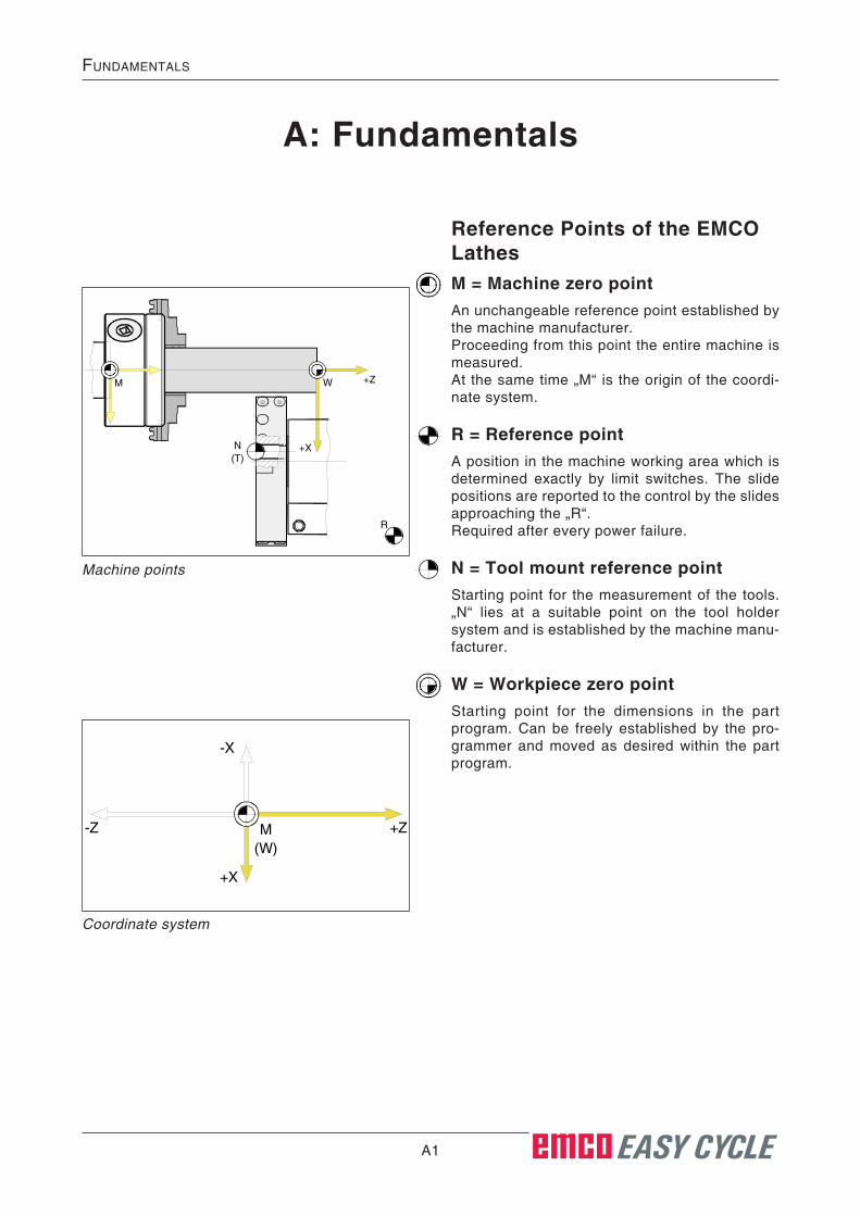
Reference Points of the EMCO LathesM = Machine zero pointAn unchangeable reference point established by the machine manufacturer.Proceeding from this point the entire machine is measured.At the same time „M“ is the origin of the coordi-nate system.
R = Reference pointA position in the machine working area which is determined exactly by limit switches. The slide positions are reported to the control by the slides approaching the „R“.Required after every power failure.
N = Tool mount reference pointStarting point for the measurement of the tools. „N“ lies at a suitable point on the tool holder system and is established by the machine manu-facturer.
W = Workpiece zero pointStarting point for the dimensions in the part program. Can be freely established by the pro-grammer and moved as desired within the part program.
Machine points
M W
R
+Z
+XN(T)
M(W)
+Z
-X
-Z
+X
Coordinate system

A2 EASY CYCLE
Fundamentals
Absolute workpiece positionsPosition coordinates that refer to the workpiece datum are called absolute coordinates.Every position of a workpiece is clearly deter-mined by absolute coordinates (picture on the top left).The origin of the coordinate system lies in the ma-chine zero point „M“, respectively in the workpiece zero point „W“ after a programmed zero offset.All target points are described from the origin of the coordinate system by definition of the respec-tive X and Z distances.X dimensions are indicated as diameter values (like dimensioning on the drawings).

A3 EASY CYCLE
Fundamentals
Zero offsetThe machine zero point "M“ of EMCO lathes is on the turning axis and on the front side of the spindle flange. This position is not suited as starting point for programming. With the so-called zero offset, the coordinate system can be shifted to a suitable point in the working area of the machine.
The control offers two methods to set a zero offset:
1.) Set the reference point (see below).2.) Cycle group coordinate transformation. Here,
absolute or incremental datum shifts can be used (see chapter D).
Zero offset from machine zero point M to work-piece zero point W
Definition of the axis value in Z direction
Example:The workpiece zero point should be defined at the front side of a turning component.Execution: Touch with a tool on the front side of a faced workpiece.• Press "Z“.
• Enter the value "0“ and confirm with "ENTER“.
• Press "ENTER“ again.
Now, the workpiece zero point W is preset in Z-axis direction with the value "0“.
Z
0
Setting the reference pointThe setting of the reference point is carried out axis by axis and serves to define the workpiece zero point.• Press the key of the required axis.
• Enter the value with which you want to preset the axis.
• To capture the entry, press "ENTER“, to abort the entry, press "ESC“. EASY CYCLE opens a dialogue box: (see center of the illustration op-posite).
To confirm, press "Enter“, to abort, press "ESC“.
X Z
ESC

A4 EASY CYCLE
Fundamentals
B1 EASY CYCLE
Key Description
PLANDREHEN 2Scharfe Ecke
Xi 0.000
Parameter
Xf 0.000
Ø 0.000
Zi 0.000
Zf 0.000
R 0.000
C 0.000
Zs 0.000Xs 0.000
X 92.884
Z 196.400
F 92.884
S 92.884
T 0 D 1
VorigeVariante
VorigeVariante
NächsteVariante
VorigeVariante
Geo-metrie
Techno-logie
Ab-brechen
Über-nehmen
X 7 8 9
4 5 6
Z 1 2 3
F . 0 -
ESC
CSS
DEL
T SHIFT
SKIPOPT.STOP
DRYRUN
D
EASY CYCLE
S
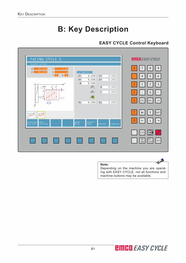
B: Key DescriptionEASY CYCLE Control Keyboard
Note:Depending on the machine you are operat-ing with EASY CYCLE, not all functions and machine buttons may be available.

B2 EASY CYCLE
Key Description
1
2 34
5
67
98
11
10
Screen layout
1 Program name and number
2 NC position displays; technology data; Softkey allows you to switch between the
reference position display and the remaining distance display.
3 Display of the actual feed and speed values
4 Display of the programmed feed and speed values
5 Tool change number; tool correction
6 Tool change position
7 Tool wear
8 Cycle list
The defined cycles of a program will be shown. The just processed cycle will be shown highlighted.
9 Status display; operating mode display; processing time;
10 Softkeys
11 Alarm and notification lines
Note:Pressing the "ESC" key takes you back to the respective higher-level menu.
B3 EASY CYCLE
Key Description
Alt
Gr
End
Del
ete
Num
Lock
Cap
sLo
ckS
crol
lLo
ck
Num
NC
-S
TAR
T
NC
-S
TOP
RE
SE
T
+C
-C-Z+Z
+X -XDR
YR
UN
SKI
P
OP
TS
TOP
SBL
<% >%
F12
WE
RT
Y
AS
DG
L
Z
Ctrl
Alt
Alt
1!
K
4$5%
O
HJ
F2
Q
= 4
= $
==
4$4$
Ctrl
Alt
ESC
Inse
rtH
ome
Prin
tS
crn
Sys
Rq
Pau
se
Bre
ak
Scr
oll
Lock
F4F1
0F1
1F3
F1JOG
Pag
eU
p
Pag
eD
own
F
F8IN
C 1
000
F9IN
C 10
000
F6INC
10
F7IN
C 1
00
F5INC
1
U
VX
= IN
C 1
00A
ltF7
INC
100
FX
CtrlCap
s Lo
ckTab
2@
/
Ent
er
Shi
ftS
hift
~ `6^
3#7&
0)9(
8*
" ´=+
/?
-
_ ]
]
Shi
ft
: ;
.>,<
MA
UX
NA
UX
BC CSS
PI
7
3
5
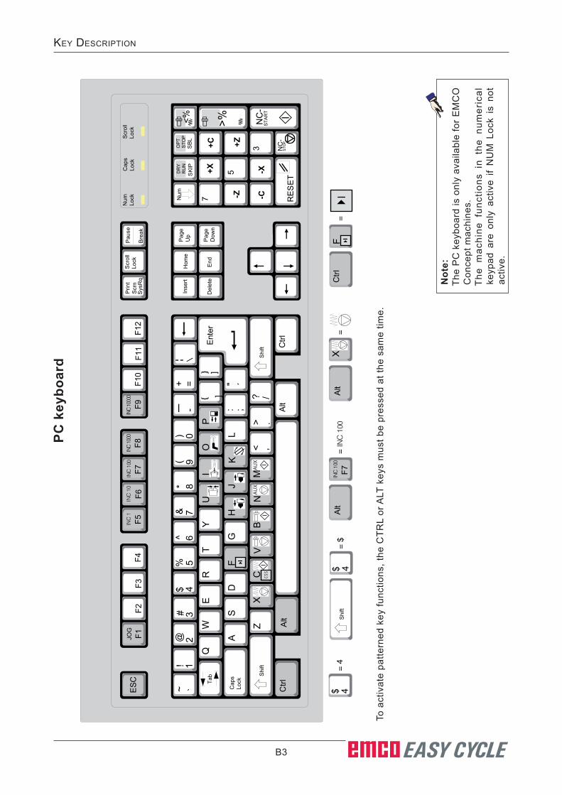
PC k
eybo
ard
To a
ctiv
ate
patte
rned
key
func
tions
, the
CTR
L or
ALT
key
s m
ust b
e pr
esse
d at
the
sam
e tim
e.
Not
e:Th
e P
C k
eybo
ard
is o
nly
avai
labl
e fo
r E
MC
O
Con
cept
mac
hine
s.T
he m
achi
ne f
unct
ions
in
the
num
eric
al
keyp
ad a
re o
nly
activ
e if
NU
M L
ock
is n
ot
activ
e.
B4 EASY CYCLE
Key Description
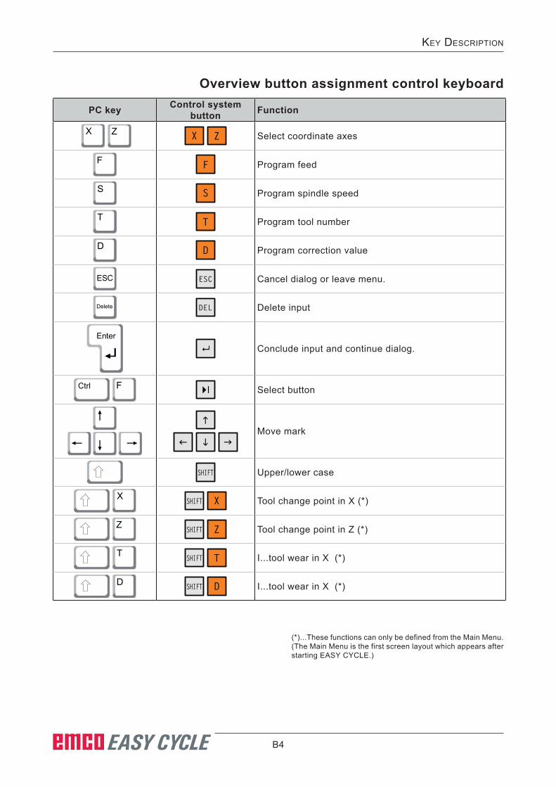
PC key Control system button Function
X
Z X
Z Select coordinate axes
F F Program feed
S S Program spindle speed
T T Program tool number
D D Program correction value
ESC ESC Cancel dialog or leave menu.
Delete DEL Delete input
Enter
Conclude input and continue dialog.
Ctrl
F Select button
Move mark
SHIFT Upper/lower case
X SHIFT
X Tool change point in X (*)
Z SHIFT
Z Tool change point in Z (*)
T SHIFT
T I...tool wear in X (*)
D SHIFT
D I...tool wear in X (*)
Overview button assignment control keyboard
(*)...These functions can only be defined from the Main Menu. (The Main Menu is the first screen layout which appears after starting EASY CYCLE.)

B5 EASY CYCLE
Key Description
PC key Control system button Function
Ctrl
C CSS Constant Cutting Speed (CCS) m/min
x Single block
0 Reset key (Reset)
Ctrl
.. DRYRUN Dryrun (test-run feed)
Ctrl
x OPT.STOP Selectable Stop
.. SKIP Skip (block mask)

B6 EASY CYCLE
Key Description
PC key Control elements Function
Alt
U Clamping device open / closed
Alt
I Internal/External Clamping (Option Concept Turn 55)
Alt
O Coolant / Purge on / off
Alt
P
Door open / closed
Alt
H Tailstock forwards
Alt
J Tailstock backwards
Alt
K Swivel tool holder
Alt
X Feed Stop
Alt
C Feed Start
Alt
V Spindle Stop
Alt
B Spindle Start
Alt
N Switch auxiliary drives on AUX OFF
Alt
M Switch auxiliary drives off AUX ON
Enter NC Start
, NC Stop
Note:Selecting the machine buttons via the PC keyboard: 1.) Hold "Alt" button down.2.) Press and then release machine button.3.) Release "Alt" button.
Overview Button Assignment Machine Operating Elements

B7 EASY CYCLE
Key Description
PC button Control elements Function
Ctrl
-
Ctrl
+Spindle speed correction
-
+Override (feed rate override)

B8 EASY CYCLE
Key Description
Key Description
Dryrun (test-run feed)In Dry-run mode, positioning movements will be carried out with the dry-run feed.The dry-run feed works instead of the programmed movement com-mands.On starting the NC program, the main spindle will not be activated and the slides will move with dry-run feed speed.Only perform the test run without a workpiece.If the test run is engaged, the test "DRY" appears in the simulation window.
DRYRUN
Constant Cutting Speed (CCS) / Constant Spindle SpeedThis function offers you the possibility of programming the speed as either constant speed or constant cutting speed (see Chapter C Operation "Speed S").
CSS
Single blockThis functions allows you to execute a program block by block.The Single Block function can be activated in the automatic mode (a program will be executed automatically) operation type.
When single block processing is active:• SBL" (=SingleBlock) is shown on the screen.• the current block of the part programis only processed when you press
the NC Start button.• processing stops after a block is executed.• the following block is executed by pressing the NC Start key
again.The function can be deselected by pressing the Single Block key again.
Reset key (Reset) • Execution of the current program is broken off.• Alarm notifications will be cleared.• The control system is in the starting position and ready for a new
program sequence.• A running program or a positioning movement will be broken off.

B9 EASY CYCLE
Key Description
NC StopAfter pressing the NC Stop button the execution of the running program will be broken off.Processing can then be continued by pressing the NC Start but-ton.
NC StartAfter pressing the NC Start key the selected program will be started with the current block.
Direction buttonsWith these buttons, the NC axes can be moved in JOG operation mode.
7 98
4 65
1 32
Selectable StopWhen this function is active, program processing will stop at blocks in which the M01 special function has been programmed.You start processing again with the NC Start button. If the function is not active, the M01 special function will be ig-nored.
OPT.STOP
Skip (block mask)In Skip mode, program blocks will be jumped over when the program is running.
SKIP

B10 EASY CYCLE
Key Description
Rapid TraverseIf this function is pressed in addition to the movement buttons, the axes concerned move in rapid traverse.
Feed StopIn "AUTOMATIC" operation mode, this function cancels a slide move-ment (not with threading).
Feed StartThis function resumes a programmed slide movement which has been interrupted.If the main spindle motion was also broken off, it must be switched on first.
Spindle StopThis function interrupts the motion of the main spindle. If it happens during a feed movement, that has to be stopped first.
Spindle StartThis function resumes the programmed spindle motion.
Spindle speed correctionThe set spindle speed value S will be shown on the screen as an absolute value and as a percentage (see Chapter C Operation "Spindle Speed Correction").
Tailstock forwards, tailstock backwardsWith these functions the tailstock is moved forwards or back-wards.
CoolantThis function switches the coolant equipment on or off.
Clamping deviceThis function activates the clamping device.
B11 EASY CYCLE
Key Description
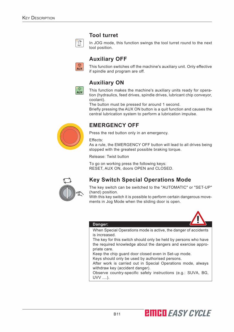
Tool turretIn JOG mode, this function swings the tool turret round to the next tool position.
Auxiliary OFFThis function switches off the machine's auxiliary unit. Only effective if spindle and program are off.
Auxiliary ONThis function makes the machine's auxiliary units ready for opera-tion (hydraulics, feed drives, spindle drives, lubricant chip conveyor, coolant).The button must be pressed for around 1 second.Briefly pressing the AUX ON button is a quit function and causes the central lubrication system to perform a lubrication impulse.
EMERGENCY OFFPress the red button only in an emergency.
Effects:As a rule, the EMERGENCY OFF button will lead to all drives being stopped with the greatest possible braking torque.
Release: Twist button
To go on working press the following keys:RESET, AUX ON, doors OPEN and CLOSED.
Key Switch Special Operations ModeThe key switch can be switched to the "AUTOMATIC" or "SET-UP" (hand) position.With this key switch it is possible to perform certain dangerous move-ments in Jog Mode when the sliding door is open.
Danger:When Special Operations mode is active, the danger of accidents is increased.The key for this switch should only be held by persons who have the required knowledge about the dangers and exercise appro-priate care. Keep the chip guard door closed even in Set-up mode.Keys should only be used by authorised persons.After work is carried out in Special Operations mode, always withdraw key (accident danger).Observe country-specific safety instructions (e.g.: SUVA, BG, UVV ....).

B12 EASY CYCLE
Key Description
REF - Reference modeApproaching the reference point (Ref) in the JOG operating mode.
AUTO - Automatic modeControl the machine by automatically executing programs.
JOG - JoggingStandard movement of the machine by continuous movement of the axes via the directional buttons or by incremental movement of the axes via the directional buttons or the handwheel.
Inc 1 - Incremental FeedMove step by step a predefined distance of 1 increment.Metrical measurement system: Inc 1 corresponds to 1µmImperial (inch-based) measurement system: Inc 1 corresponds to 0.0001 inches
Inc 10 - Incremental FeedMove step by step a predefined distance of 10 increments.Metrical measurement system: Inc 10 corresponds to 10µmImperial (inch-based) measurement system: Inc 10 corresponds to 0.001 inches
Inc 100 - Incremental FeedMove step by step a predefined distance of 100 increments.Metrical measurement system: Inc 100 corresponds to 100µmImperial (inch-based) measurement system: Inc 100 corresponds to 0.25 mm
Inc 1000 - Incremental FeedMove step by step a predefined distance of 1000 increments.Metrical measurement system: Inc 1000 corresponds to 1000µmImperial (inch-based) measurement system: Inc 1000 corresponds to 0.1 inch
Inc 10000 - Incremental FeedMove step by step a predefined distance of 10,000 increments.Metrical measurement system: Inc 10000 corresponds to 10000µmImperial (inch-based) measurement system: Inc 10000 corresponds to 1 inch
AUTO
JOG
Types of operation
Note:Switching between the metrical measurement system and the imperial (inch-based) measurement system is carried out with the EmConfig utility software (see Chapter X EmConfig).

B13 EASY CYCLE
Key Description
USB connection (USB 2.0)Data is exchanged with the machine (data copying, software instal-lation) via this USB connection.
Override switch (feed rate override)The rotary switch enables you to change the programmed feed value F (corresponds to 100%).The set feed value F in % will be shown on the screen (see Chapter C Operation "Feed Rate Override").

B14 EASY CYCLE
Key Description
C1 EASY CYCLE
OperatiOn
C: Operation
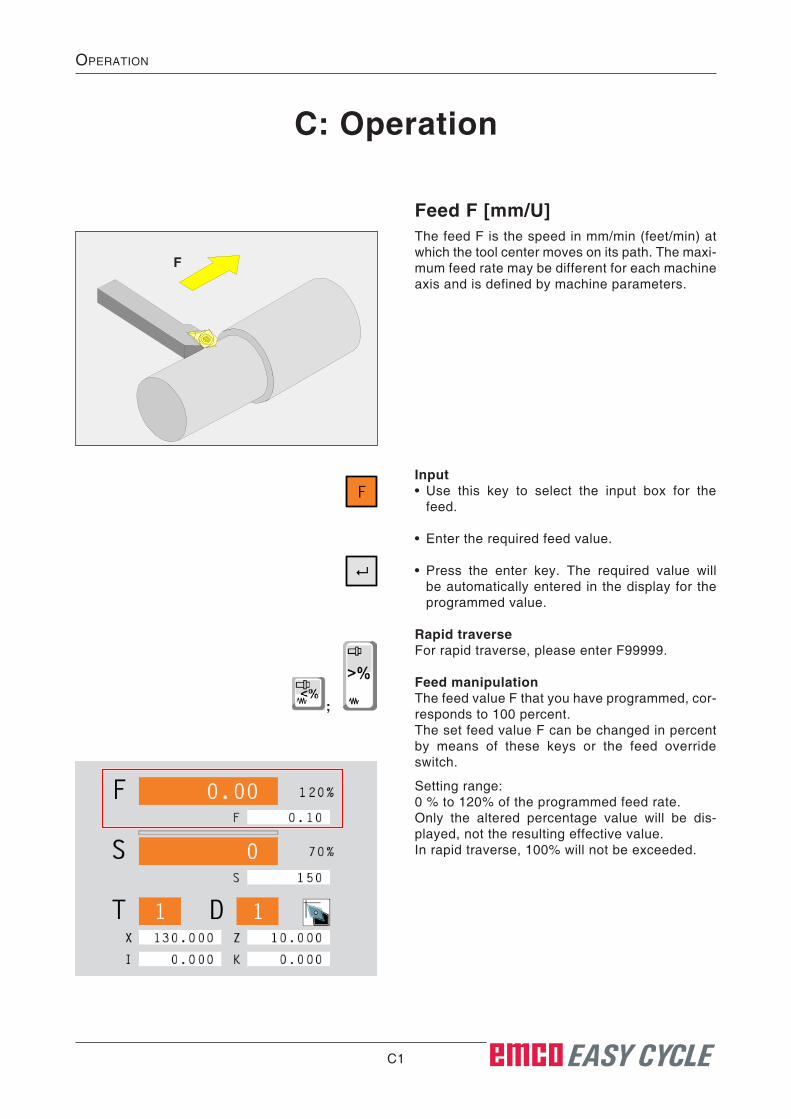
Feed F [mm/U]The feed F is the speed in mm/min (feet/min) at which the tool center moves on its path. The maxi-mum feed rate may be different for each machine axis and is defined by machine parameters.
F
Input• Use this key to select the input box for the
feed.
• Enter the required feed value.
• Press the enter key. The required value will be automatically entered in the display for the programmed value.
Rapid traverseFor rapid traverse, please enter F99999.
Feed manipulationThe feed value F that you have programmed, cor-responds to 100 percent.The set feed value F can be changed in percent by means of these keys or the feed override switch.
Setting range:0 % to 120% of the programmed feed rate.Only the altered percentage value will be dis-played, not the resulting effective value.In rapid traverse, 100% will not be exceeded.
F
;

C2 EASY CYCLE
OperatiOn
Z
X1
3
M
2
Speed fundamentalsYou choose between the following procedures:
• Spindle speed S: You program the spindle speed directly. The
spindle speed is independent of the diameter on which the tool works.
• Constant Cutting Speed CCS: You program the spindle speed indirectly. The
control system changes the speed depending on which diameter the tool is working directly. In this way a constant cutting speed will be achieved.
Example:• Spindle speed S: Section 1 to 3: same speed.
• Constant Cutting Speed CCS: Section 1: high speed. Section 2: constantly increasing speed. Section 3: low speed.

C3 EASY CYCLE
OperatiOn
Spindle speed S [rpm]The spindle speed S is entered in rotations per minute (1/min).
Input• Use this key to select the input box for the
spindle speed.
• Enter the required spindle speed.
• Press the enter key. The required value will be automatically entered in the display for the programmed value.
Spindle speed correctionThe spindle speed S you have programmed, cor-responds to 100%.The set spindle speed value S can be changed in percent by means of these key sequences or the spindle override switch.
Setting range:0% to 120% of the programmed spindle speed.Only the altered percentage value will be dis-played, not the resulting effective value.
S
;
S

C4 EASY CYCLE
OperatiOn
Constant cutting speed [m/min]Enter the constant cutting speed CSS in (m/min) or in (ft/min).
When the constant cutting speed is activated, the spindle speed is automatically changed in a way, always depending on the workpiece diameter, that the cutting speed S in (m/min or inch/min) will remain constant at the tool edge. Thus, you get smoother turning surfaces and therefore a higher surface quality.
If a workpiece with a large diameter difference is machined, the entry of a spindle speed limitation is recommended. Through this, non-permissibly high spindle speeds for small diameters can be avoided.
• Use this key to select the input box for the spindle speed.
• Enter the required spindle speed.
Activate CSS• Activation of the constant cutting speed. The
programmed spindle speed S is automati-cally converted into the constant cutting speed CSS.
• Enter the constant cutting speed required.
• Enter the spindle speed limitation Smax.
Deactivate CSS• By pressing the CSS key again, the constant
cutting speed is deactivated. The programmed constant cutting speed CSS is automatically converted into the spindle speed S.
S
CSS
S
CSS
C5 EASY CYCLE
OperatiOn
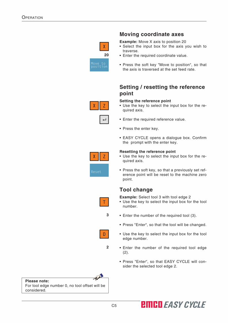
Tool changeExample: Select tool 3 with tool edge 2• Use the key to select the input box for the tool
number.
• Enter the number of the required tool (3).
• Press "Enter“, so that the tool will be changed.
• Use the key to select the input box for the tool edge number.
• Enter the number of the required tool edge (2).
• Press "Enter“, so that EASY CYCLE will con-sider the selected tool edge 2.
T
3
D
2
Moving coordinate axesExample: Move X axis to position 20• Select the input box for the axis you wish to
traverse.• Enter the required coordinate value.
• Press the soft key "Move to position“, so that the axis is traversed at the set feed rate.
X
20
Move toposition
Setting / resetting the reference pointSetting the reference point• Use the key to select the input box for the re-
quired axis.
• Enter the required reference value.
• Press the enter key.
• EASY CYCLE opens a dialogue box. Confirm the prompt with the enter key.
Resetting the reference point• Use the key to select the input box for the re-
quired axis.
• Press the soft key, so that a previously set ref-erence point will be reset to the machine zero point.
X Z
X Z
Reset
Please note:For tool edge number 0, no tool offset will be considered.

C6 EASY CYCLE
OperatiOn
X...tool changing point in X
Z...tool changing point in Z
I...tool wear in X
K...tool wear in Z
SHIFT X
SHIFT Z
SHIFT T
SHIFT D
Define tool change pointYou can define the tool change point with the X and Z coordinates. The coordinates of the work-piece change point are relative to the machine zero point. Prior to the tool change, this posi-tion will be approached with the slide reference point.
The tool change point should be selected in such a way that no collisions can occur during the tool change.
The tool change point and the tool wear are defined from the main menu with the following button combinations: (The Main Menu is the first screen layout which appears after starting EASY CYCLE.)

C7 EASY CYCLE
OperatiOn
Program managementA program consists of a succession of cycles.Press the soft key in order to get into the program management.
In the program list on the left, the workpiece programs that are stored by EASY CYCLE, are displayed. The cycle list on the right shows the cycles contained.
On the top right you see the program that has been selected at the machine (here: "P3 - Stepped Shaft").
In case there exist more programs than the ones displayed in the window, use the cursor keys in order to move through the list or press the soft key "Go to“.
With these cursor keys, you can switch between the lists. The active list is always highlighted in light grey.
The program management offers you the follow-ing possibilities:
• creating a program
For marked entries (highlighted in light grey):• deleting a program• copying a program• changing a program• selecting / deselecting a program at the ma-
chine
Programs
Go to
Instructions:We recommend regular data backup, to prevent the resultant data loss in the event of a defect.
C8 EASY CYCLE
OperatiOn
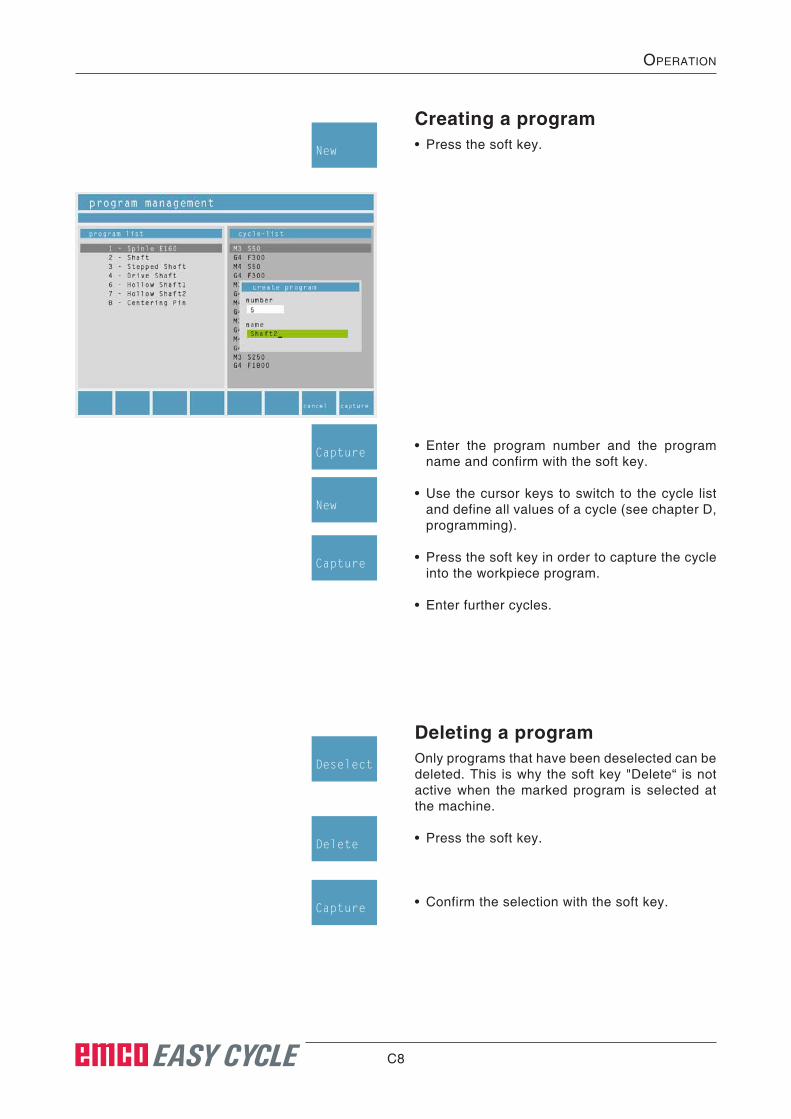
Creating a program• Press the soft key.New
Deleting a programOnly programs that have been deselected can be deleted. This is why the soft key "Delete“ is not active when the marked program is selected at the machine.
• Press the soft key.
• Confirm the selection with the soft key.
Deselect
Delete
Capture
• Enter the program number and the program name and confirm with the soft key.
• Use the cursor keys to switch to the cycle list and define all values of a cycle (see chapter D, programming).
• Press the soft key in order to capture the cycle into the workpiece program.
• Enter further cycles.
Capture
New
Capture

C9 EASY CYCLE
OperatiOn
Copying a program• Move the highlight on the required program.
• Press the soft key.
• Allocate a program number and a name.
Copy
• Enter the program number and the program name and confirm with the soft key.
Capture
Renaming a program• Move the highlight on the required program.
• Press the soft key. The soft key is only active when the program is not selected.
• Allocate a program number and a name.
• Press the soft key in order to capture the new values.
Rename
Capture
Selecting / deselecting a pro-gram at the machine• Move the highlight on the required program.
• Press the soft key.
• A marked program is automatically selected by switching to the cycle list.
DeselectSelect
Please note:When you create, copy and rename a program, the alarm message line displays "file <number> ex-ists (replace / edit)“, if the program number you have allocated does already exist. Program names can be allocated several times.

C10 EASY CYCLE
OperatiOn
Editing the program• Move the highlight on the required program.
• Switch into the cycle list.
• Move the highlight on the required cycle.
Shifting the cycle• Press the soft key.
Cut
• Move the highlight on the position prior to which the cycle shall be inserted.
• Press the soft key. Insert
Editing the cycle• Press the "ENTER“ key.
• Carry out the modifications in the cycle.
• Press the soft key.
Capture

C11 EASY CYCLE
OperatiOn
Deleting the cycle• Press the soft key.Delete
• Confirm the selection with the soft key. Capture
Adding a new cycle• Press the soft key.
• Use the soft key to open the cycle you wish to add.
• Enter all necessary cycle parameters.
New
Grooving
Threadcutting
Facing
Long.turning
TaperturningPositionBore
Contourturning
Radiusturning
Callsubprog.
Coord.trans.
Isoedit
• Confirm the selection with the soft key. Capture
Copying the cycle• Press the soft key.
• Move the highlight on the position prior to which the cycle shall be inserted.
• Press the soft key.
Copy
Insert

C12 EASY CYCLE
OperatiOn
NC import / exportYou can import or export programs, contours and the tool table by means of an USB keychain.
• Press the soft key and you will get from the program or contour management to the import / export window.
• Use the cursor keys to select, whether you wish to export or import.
The symbol indicates the file transfer direc-tion.
• In order to export, import or delete files, select all files or single files.
When you press the soft key "Delete“ in the pro-gram list, all programs will be deleted except for the file you have selected at the machine.
• Press the soft key to select the required file in order to import, export, delete or rename it.
Import/Export
Selectsingle
Selectall
Go to
Export• Press the soft key. The file that has been se-
lected in the program list or in the contour list will be displayed in the USB program list or the USB contour list.
Export

C13 EASY CYCLE
OperatiOn
Import• Press the soft key. The file that has been select-
ed in the USB program list or the USB contour list will be displayed in the program list or in the contour list.
Import
Please note:When the number of a file in the transfer tar-get has already been allocated, you will be prompted to enter a new number for the target (see left-hand illustration). If you select an already existing number, the alarm message line will display "file <number> exists (replace / change)“. You can either overwrite the file that is saved in the target or alter the number (see bottom left-hand illustration). File num-bers are definite parameters. File names can be allocated several times.
Datei 2 existiert (Ersetzen / Ändern)

C14 EASY CYCLE
OperatiOn
Graphical simulationWith the graphical simulation, geometrial errors are recognised, e.g. wrong positions, contour infringements, wrong tool etc.Technological errors will not be recognised e.g. wrong speed or feeds.There are two possibilities for simulating a cycle in 2D or 3D mode (only with EMCO Win 3D View accessory software):• in the cycle menu: After definition, the cycle can
be simulated immediately.• in Programme Management: The cycles saved
in a program will be simulated.
Note:The EMCO Win 3D View software is an acces-sory to EASY CYCLE and enables the three-dimensional simulation of CNC programs on the screen.
Simulate cycle• Call up Cycle in the Cycle menu (see Chapter
D Programming "Cycles") and enter all required cycle parameters (geometry data and technol-ogy data).
Direct simulation in the Cycles menu
Conclude the input with this Softkey.
• Press Softkey.
• This Softkey allows later optimisations to the cycle to be carried out.
Capture
Sim
Cancel
C15 EASY CYCLE
OperatiOn
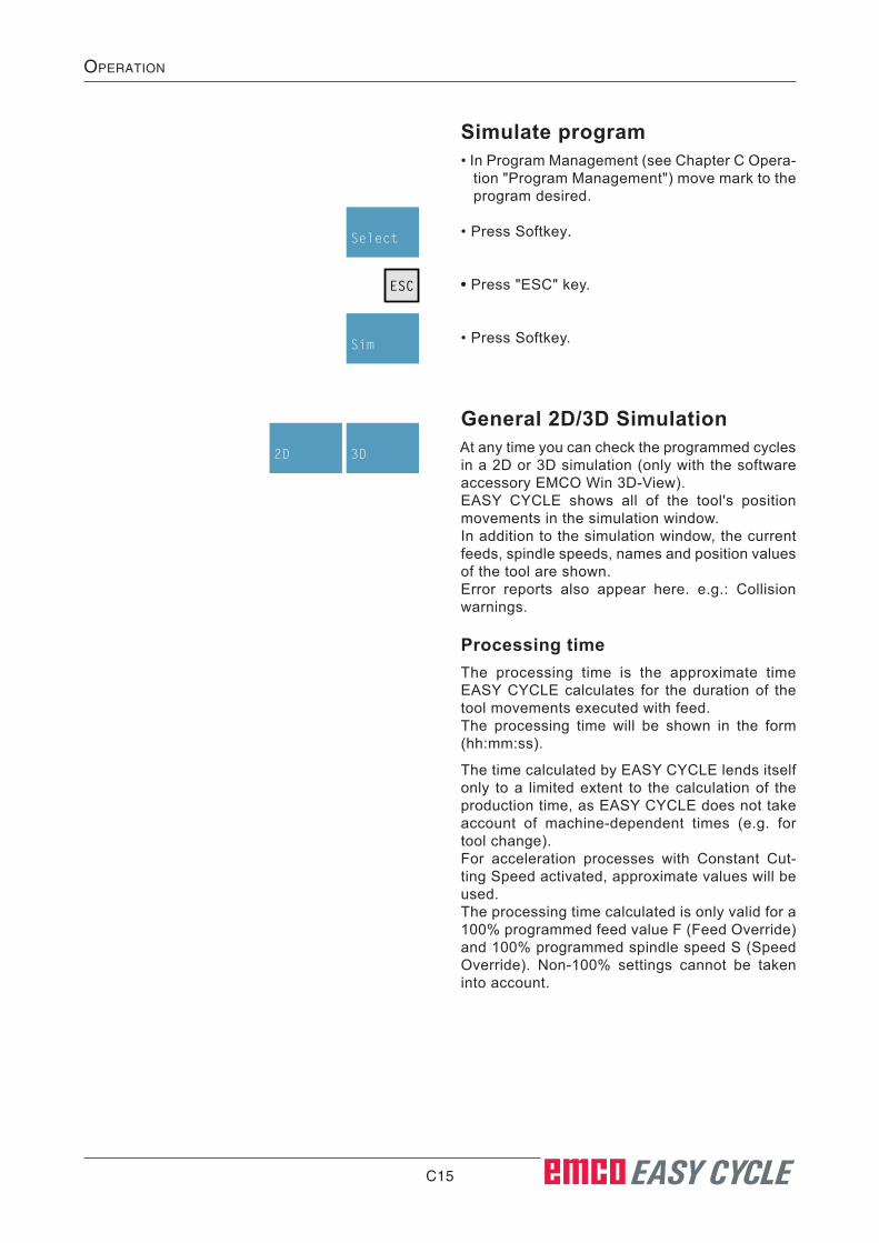
Simulate program• In Program Management (see Chapter C Opera-
tion "Program Management") move mark to the program desired.
• Press Softkey.
• Press "ESC" key.
• Press Softkey.
Select
ESC
Sim
General 2D/3D SimulationAt any time you can check the programmed cycles in a 2D or 3D simulation (only with the software accessory EMCO Win 3D-View).EASY CYCLE shows all of the tool's position movements in the simulation window.In addition to the simulation window, the current feeds, spindle speeds, names and position values of the tool are shown.Error reports also appear here. e.g.: Collision warnings.
Processing timeThe processing time is the approximate time EASY CYCLE calculates for the duration of the tool movements executed with feed. The processing time will be shown in the form (hh:mm:ss).
The time calculated by EASY CYCLE lends itself only to a limited extent to the calculation of the production time, as EASY CYCLE does not take account of machine-dependent times (e.g. for tool change).For acceleration processes with Constant Cut-ting Speed activated, approximate values will be used. The processing time calculated is only valid for a 100% programmed feed value F (Feed Override) and 100% programmed spindle speed S (Speed Override). Non-100% settings cannot be taken into account.
3D2D

C16 EASY CYCLE
OperatiOn
FrameFor a better view, you may switch over into the frame mode.
Frame
Starting the simulationThe simulation is started by means of this soft key. In order to be able start the simulation, an EASY CYCLE program must have been selected. The program name and the program number of the currently selected EASY CYCLE program are displayed on the top right of the simulation window.
Start
Stopping the simulationThe simulation and the CNC program are stopped by means of this soft key. The simulation can be continued with "Start".
Stop
2D Simulation
C17 EASY CYCLE
OperatiOn
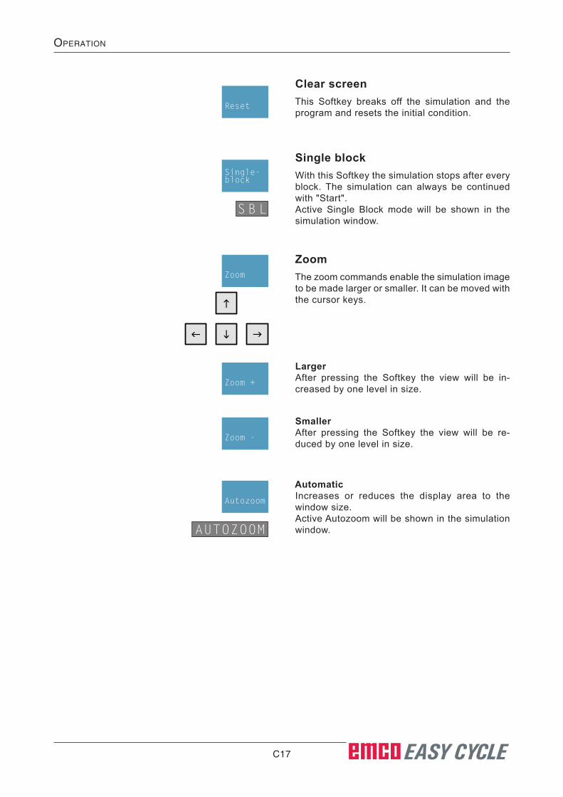
ZoomThe zoom commands enable the simulation image to be made larger or smaller. It can be moved with the cursor keys.
Zoom
SmallerAfter pressing the Softkey the view will be re-duced by one level in size.
Zoom -
AutomaticIncreases or reduces the display area to the window size.Active Autozoom will be shown in the simulation window.
Autozoom
AUTOZOOM
Clear screenThis Softkey breaks off the simulation and the program and resets the initial condition.
Reset
Single blockWith this Softkey the simulation stops after every block. The simulation can always be continued with "Start".Active Single Block mode will be shown in the simulation window.
Single-block
S B L
LargerAfter pressing the Softkey the view will be in-creased by one level in size.
Zoom +

C18 EASY CYCLE
OperatiOn
3D simulation with EMCO Win 3D-View• Press Softkey to switch to 3D mode.3D
Note:The EMCO Win 3D View software is an acces-sory to EASY CYCLE and enables the three-dimensional simulation of CNC programs on the screen.EMCO Win 3D-View is available only in .pro-gramming stations.
Entering the basic settings• Press Softkey.
• Press Softkey. You can make the following ad-justments:
Settings
Params
Display type
Normal display Wireframe completeWireframe
Transparent raw part 2D Shaded Profile

C19 EASY CYCLE
OperatiOn
ResolutionThe higher the resolution, the more precise the construction of the 3D image will be.
SpeedWith the speed setting the simulation can be slowed down or speeded up.
Sectional viewThe sectional display permits the observation of processes which would normally be covered. The representations opposite are available for selection:
Clamping devicevisible/invisible
Quillvisible/invisible
Toolsvisible/invisible
Collision checkingCollision checking monitors the following situa-tions:• Contacts between tool and clamping device.
If clamping device representation is switched off, clamping device collisions will not be moni-tored.
• Contacts between non-cutting tool parts with the workpiece or the clamping device.
If a collision occurs, the collision type will be shown and the simulation will be broken off.
full 3D sectional view
3/4 sectional view
1/2 sectional view
1/4 sectional view

C20 EASY CYCLE
OperatiOn
Raw part definition• Press Softkey.
• Press Softkey. You can enter the following val-ues:
Settings
Rawpart
Note:All values are relative to the workpiece zero point (W).
DExternal diameter.
dInternal diameter (if available).
Z1Measurement from workpiece zero point (W) to the rear facing side of the workpiece.
Z2Measurement from workpiece zero point (W) to the forward facing side of the workpiece.
sZMeasurement from the front side of the collet to the forward facing side of the workpiece (jut-out length of the raw part from the clamping de-vice).
Note:Active zero point shifts (see Chapter D Pro-gramming "Coordinate Transformation") will not be taken into account by the program. If there are active zero point shifts, therefore, the values for the raw part definition must be adjusted.
C21 EASY CYCLE
OperatiOn
Z
XW (0, 0)
M
Z
X
W (0, 0)M
Z
X
W (0, 0)M
180.000Z1
0.000Z2
0.000Z1
180.000Z2
180.000Z1
2.000Z2
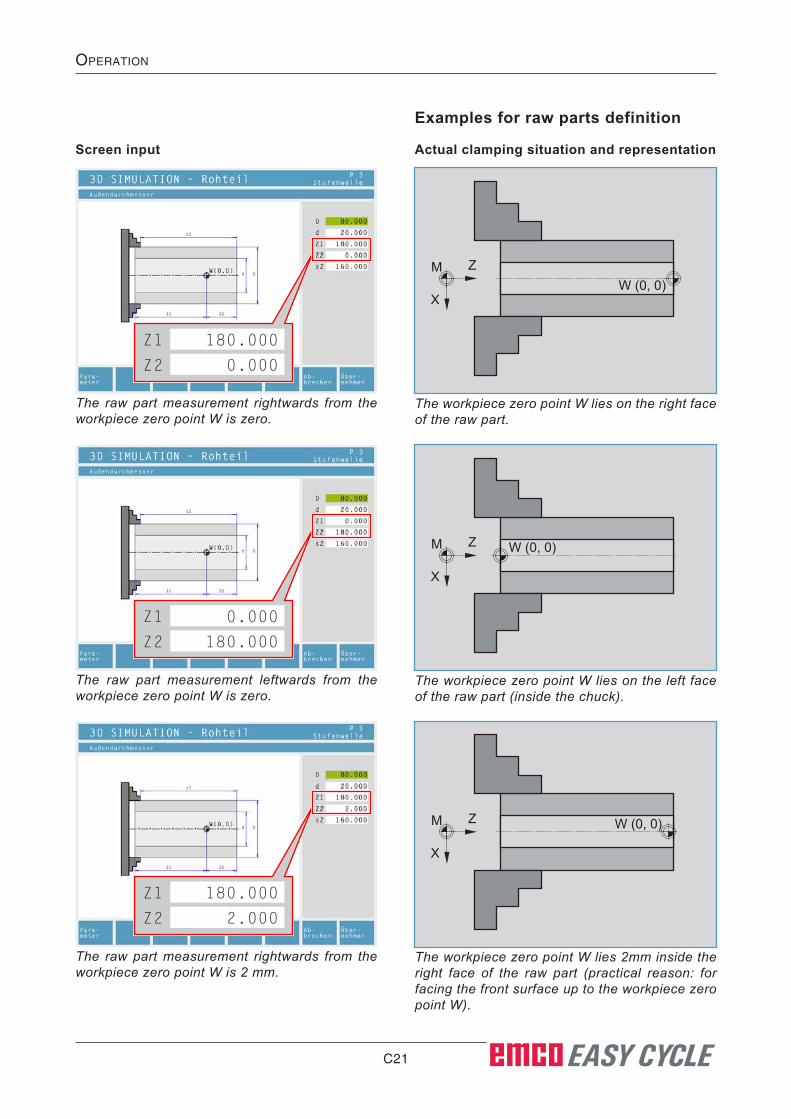
Examples for raw parts definition
Screen input Actual clamping situation and representation
The raw part measurement rightwards from the workpiece zero point W is zero.
The workpiece zero point W lies on the right face of the raw part.
The raw part measurement leftwards from the workpiece zero point W is zero.
The workpiece zero point W lies on the left face of the raw part (inside the chuck).
The raw part measurement rightwards from the workpiece zero point W is 2 mm.
The workpiece zero point W lies 2mm inside the right face of the raw part (practical reason: for facing the front surface up to the workpiece zero point W).

C22 EASY CYCLE
OperatiOn
Shift
Ctrl
SimulationIn addition to the 2D-mode functions described, the following are also possible in 3D-mode:
Rotate image
Zoom
Shift

C23 EASY CYCLE
OperatiOn
Tool modelling with the 3D-Tool Generator
1 Register cards for "Geometry", "General" and "Machines" for drilling and milling tools and "Tip", "Holder", "General" and "Machines" for turning tools.
2 Selection of tool types3 This window enables the input of tool dimen-
sions.4 Graphical support for the tool dimensioning5 Choice of tools for the selected tool type6 Choice of tool types (here: only drill) "Turning tool", "Milling tool" and "Drilling
tool" reduce the tool choice to the respective type
(here: only drilling tools are listed). "All" does not reduce the tool choice.
7 Buttons for quickly browsing through the tools go to first tool in the group
go to last tool in the group
go forward in the list by one tool
go back in the list by one tool
8 Button to delete tools9 Button to create new tools10 Button to copy tools11 Button to save changes12 Button for 3D visualization13 Button to sort tools14 Button to terminate the 3DView tool genera-
tor
With the 3D-ToolGenerator you can modify exist-ing tools and create new tools.
1
2
3 4
5 6 7 98
11
10
12 13 14
B2008-12
C24 EASY CYCLE
OperatiOn
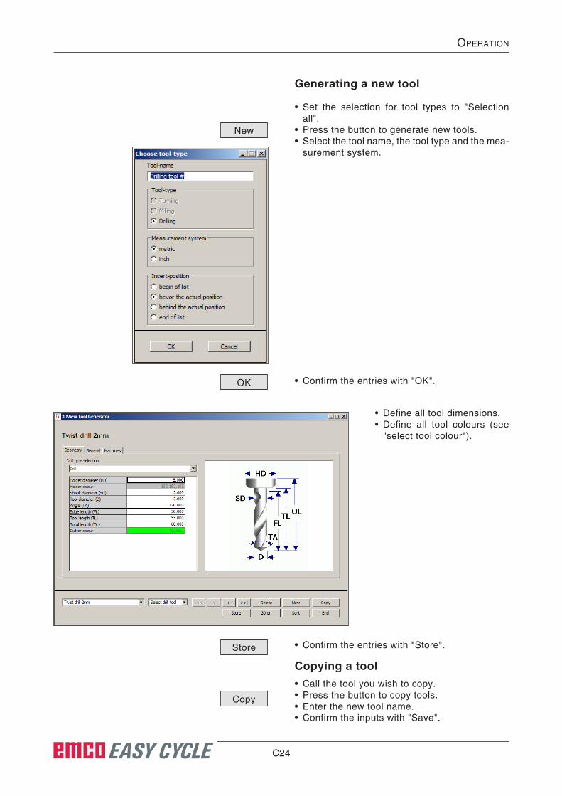
Generating a new tool
• Set the selection for tool types to "Selection all".
• Press the button to generate new tools.• Select the tool name, the tool type and the mea-
surement system.
• Confirm the entries with "OK".
• Define all tool dimensions.• Define all tool colours (see
"select tool colour").
• Confirm the entries with "Store".
Copying a tool• Call the tool you wish to copy.• Press the button to copy tools.• Enter the new tool name.• Confirm the inputs with "Save".
New
Store
OK
Copy
C25 EASY CYCLE
OperatiOn
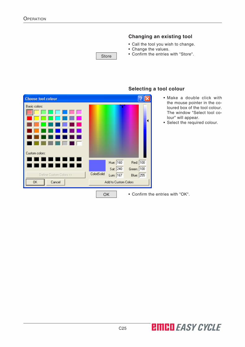
Selecting a tool colour
• Make a double click with the mouse pointer in the co-loured box of the tool colour. The window "Select tool co-lour" will appear.
• Select the required colour.
• Confirm the entries with "OK".
Changing an existing tool• Call the tool you wish to change.• Change the values.• Confirm the entries with "Store".Store
OK
C26 EASY CYCLE
OperatiOn
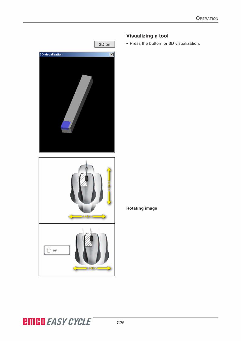
Visualizing a tool• Press the button for 3D visualization.3D on
Rotating image
Shift
C27 EASY CYCLE
OperatiOn
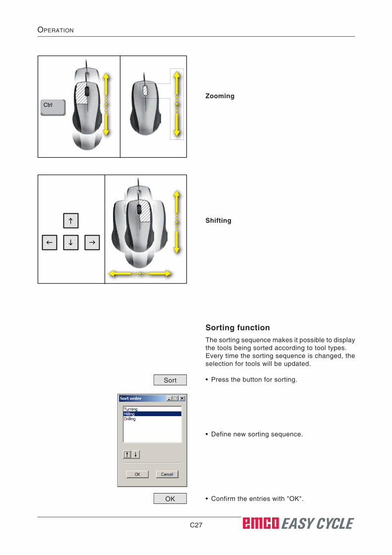
CtrlZooming
Shifting
Sorting functionThe sorting sequence makes it possible to display the tools being sorted according to tool types.Every time the sorting sequence is changed, the selection for tools will be updated.
• Press the button for sorting.
• Define new sorting sequence.
• Confirm the entries with "OK".
Sort
OK

C28 EASY CYCLE
OperatiOn
C29 EASY CYCLE
OperatiOn
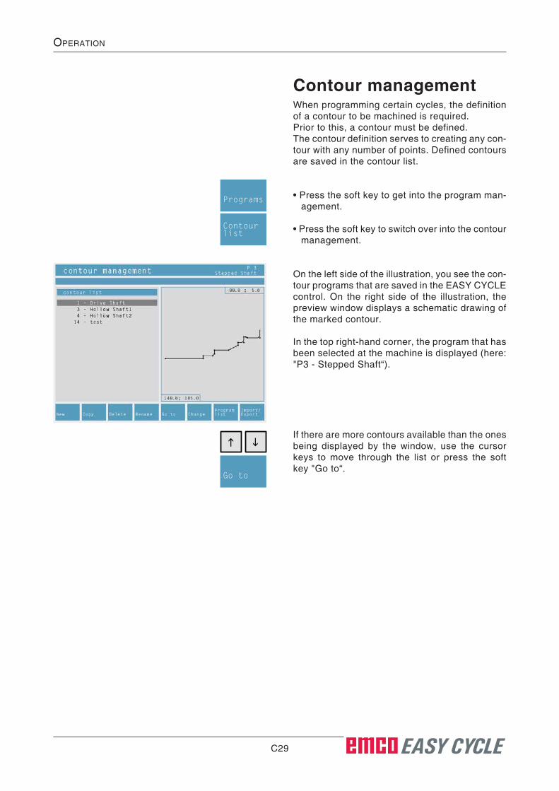
Contour managementWhen programming certain cycles, the definition of a contour to be machined is required.Prior to this, a contour must be defined.The contour definition serves to creating any con-tour with any number of points. Defined contours are saved in the contour list.
• Press the soft key to get into the program man-agement.
• Press the soft key to switch over into the contour management.
On the left side of the illustration, you see the con-tour programs that are saved in the EASY CYCLE control. On the right side of the illustration, the preview window displays a schematic drawing of the marked contour.
In the top right-hand corner, the program that has been selected at the machine is displayed (here: "P3 - Stepped Shaft“).
Programs
Contourlist
If there are more contours available than the ones being displayed by the window, use the cursor keys to move through the list or press the soft key "Go to“.
Go to
C30 EASY CYCLE
OperatiOn
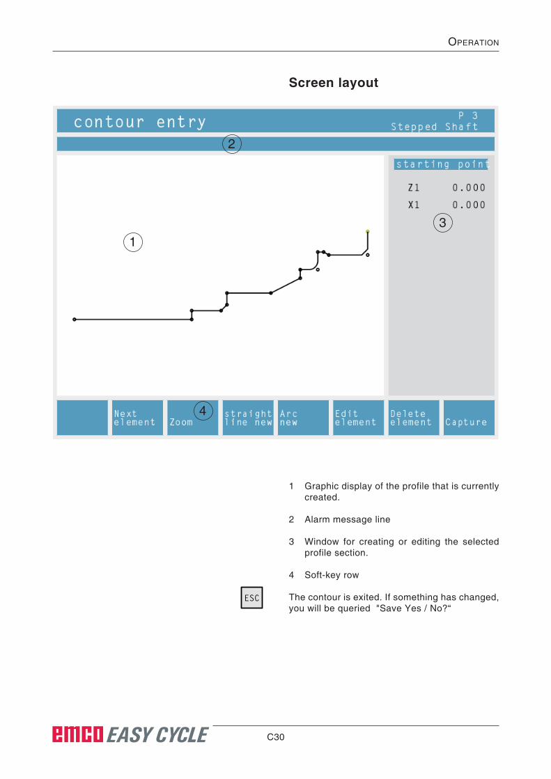
Screen layout
1 Graphic display of the profile that is currently created.
2 Alarm message line
3 Window for creating or editing the selected profile section.
4 Soft-key row
The contour is exited. If something has changed, you will be queried "Save Yes / No?“
ESC
1
2
3
4
C31 EASY CYCLE
OperatiOn
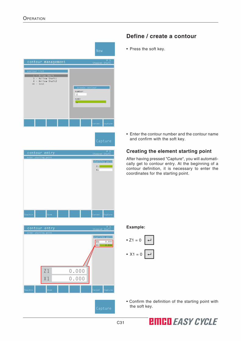
Define / create a contour
• Press the soft key.New
• Enter the contour number and the contour name and confirm with the soft key.
Capture
Creating the element starting pointAfter having pressed "Capture“, you will automati-cally get to contour entry. At the beginning of a contour definition, it is necessary to enter the coordinates for the starting point.
Example:
• X1 = 0
• Z1 = 0
• Confirm the definition of the starting point with the soft key.
Capture
0.000Z1
0.000X1

C32 EASY CYCLE
OperatiOn
Editing an elementFor alteration of value inputs of an element defi-nition.
• Move the highlight on the required contour.
• Press the "ENTER“ key.
• Select the element in the contour. These soft keys serve to forward or backward movement in the contour, element by element.
The current position in the contour is marked with green colour.
• Edit the element. Carry out the changings in the contour.
• Confirm the alterations with the soft key.
Previouselement
Nextelement
Editelement
Capture
See chapter C Operation "Graphic illustration“.
Zoom
TeachInTeachIn enables you to directly capture the cur-rent tool position in the contour definition.
TeachIn
These soft keys serve to directly capture the re-spective axis positions.Capture
ZCaptureX
Capturepoint

C33 EASY CYCLE
OperatiOn
Deleting an element• By pressing the soft keys, move the highlight to
the element you wish to delete. The element will be displayed in green colour.
• Press the soft key.
• Confirm the alterations with the soft key.
Previouselement
Nextelement
Deleteelement
Capture
Creating the element straight line• By pressing the soft keys, move the highlight to
the element where the new straight line shall be inserted. The element will be displayed in green colour.
• Press the soft key.
Previouselement
Nextelement
Straightline new
1 Coordinate values of the starting point of the straight line.
These values cannot be changed because they correspond to the last point of the previ-ous element.
2 Coordinate values of the end point of the
straight line.
3 Angle between the straight line and the ab-sciss.
4 Length of the straight line.
5 Indicates, whether the straight line to be drawn runs tangentially to the previous section. Use the selection key to make your choice.
1
2
3
45
6
6 Enter the radius for the rounding or the cham-fer. Switchable by soft key.Rounding Chamfer
• Confirm the alterations with the soft key.
• Alterations that have been carried out, will be cancelled.
Capture
ESC Cancel

C34 EASY CYCLE
OperatiOn
Creating the arc element• By pressing the soft keys, move the highlight
to the element where the new arc shall be in-serted.
The element will be displayed in green colour.
• Press the soft key.
Previouselement
Nextelement
Arcnew
1 Coordinate values of the starting point of the arc element.
These values cannot be changed because they correspond to the last point of the previ-ous element.
2 Coordinate value of the end point of the arc element.
3 Coordinate value of the center of the arc ele-ment.
4 Radius of the arc element.
5 Indicates, whether the circular arc to be drawn runs tangentially to the previous section.
1
2
3
4
5
6
6 Enter the radius for the rounding or the cham-fer. Switchable by soft key.
7 Circular arc in clockwise direction or in coun-ter-clockwise direction. Switchable by soft key.
Rounding Chamfer
Switchdir.
• Confirm the alterations with the soft key.
• Alterations that have been carried out, will be cancelled.
Capture
ESC Cancel

C35 EASY CYCLE
OperatiOn
Defining contours clearlyIf a contour cannot be clearly defined, you have to make your selection by means of the soft key.
EASY CYCLE uses different colours to display profiles:
Nextsolution
black
green
blue
red The element has not been completely defined or it has been apparently defined contradictorily.
The element is clearly defined.
Marks the current element.
From several solutions, no element has been defined yet.
Copying, deleting, renaming, chaning and importing / export-ing a contour• You may also copy, delete, rename, change,
import or export a contour. The working principle of these soft keys is the same as for the soft keys in the program management.
Import/Export
Rename
DeleteCopyChange
C36 EASY CYCLE
OperatiOn
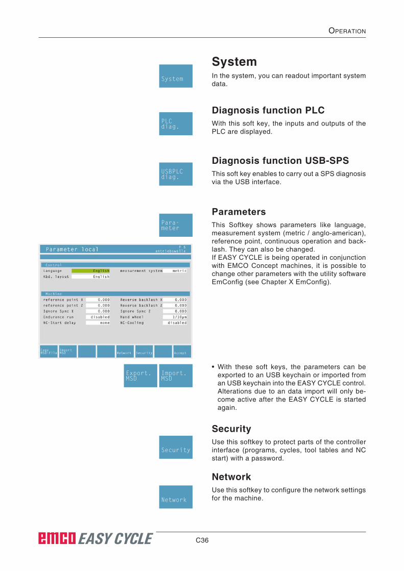
SystemIn the system, you can readout important system data.
System
Diagnosis function PLCWith this soft key, the inputs and outputs of the PLC are displayed.
PLCdiag.
Diagnosis function USB-SPSThis soft key enables to carry out a SPS diagnosis via the USB interface.
USBPLCdiag.
• With these soft keys, the parameters can be exported to an USB keychain or imported from an USB keychain into the EASY CYCLE control. Alterations due to an data import will only be-come active after the EASY CYCLE is started again.
Export.MSD
Import.MSD
ParametersThis Softkey shows parameters like language, measurement system (metric / anglo-american), reference point, continuous operation and back-lash. They can also be changed.If EASY CYCLE is being operated in conjunction with EMCO Concept machines, it is possible to change other parameters with the utility software EmConfig (see Chapter X EmConfig).
Para-meter
SecurityUse this softkey to protect parts of the controller interface (programs, cycles, tool tables and NC start) with a password.
NetworkUse this softkey to configure the network settings for the machine.
Security
Network
C37 EASY CYCLE
OperatiOn
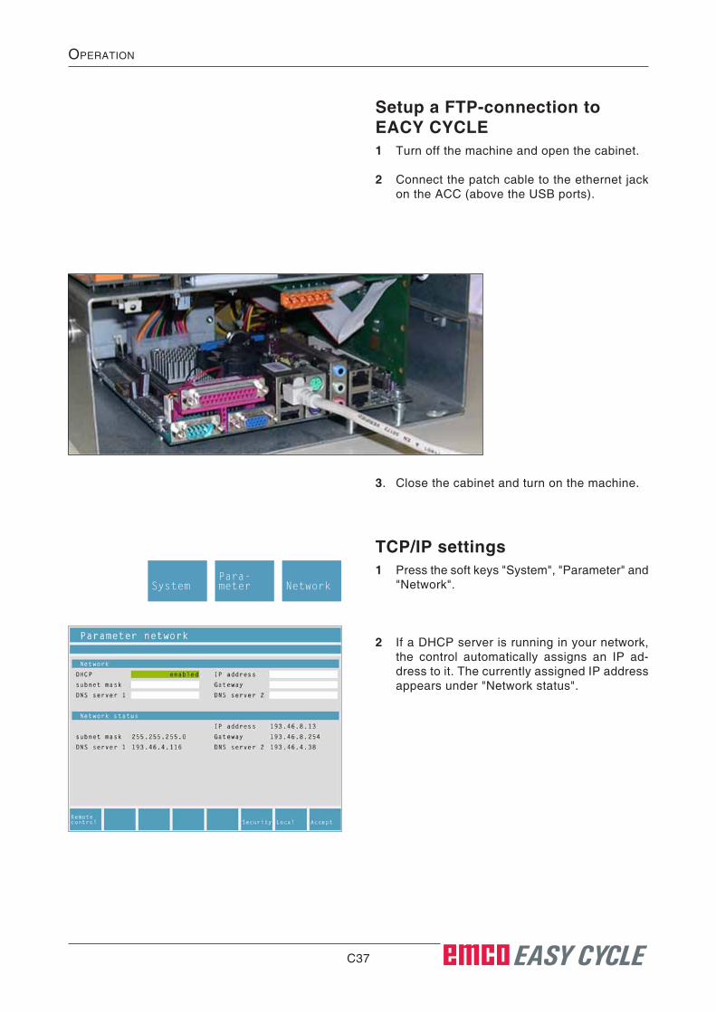
Setup a FTP-connection to EACY CYCLE1 Turn off the machine and open the cabinet.
2 Connect the patch cable to the ethernet jack on the ACC (above the USB ports).
3. Close the cabinet and turn on the machine.
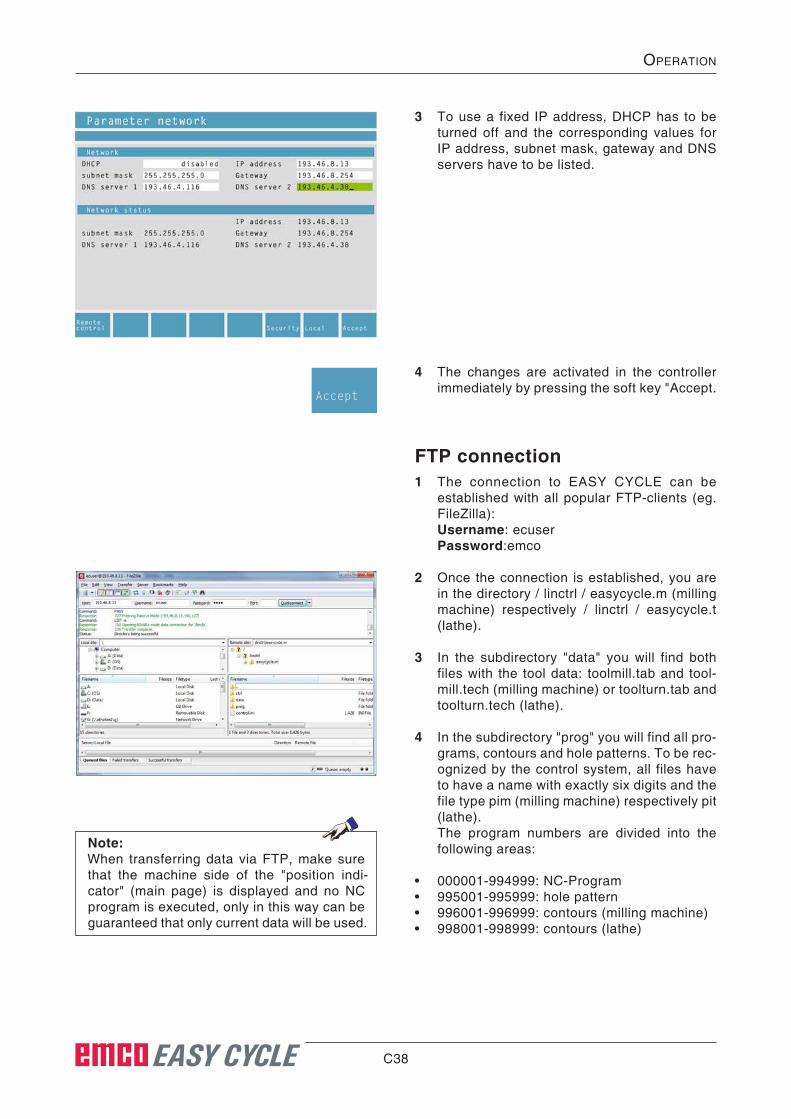
TCP/IP settings1 Press the soft keys "System", "Parameter" and
"Network".
2 If a DHCP server is running in your network, the control automatically assigns an IP ad-dress to it. The currently assigned IP address appears under "Network status".
Para-meterSystem Network
C38 EASY CYCLE
OperatiOn
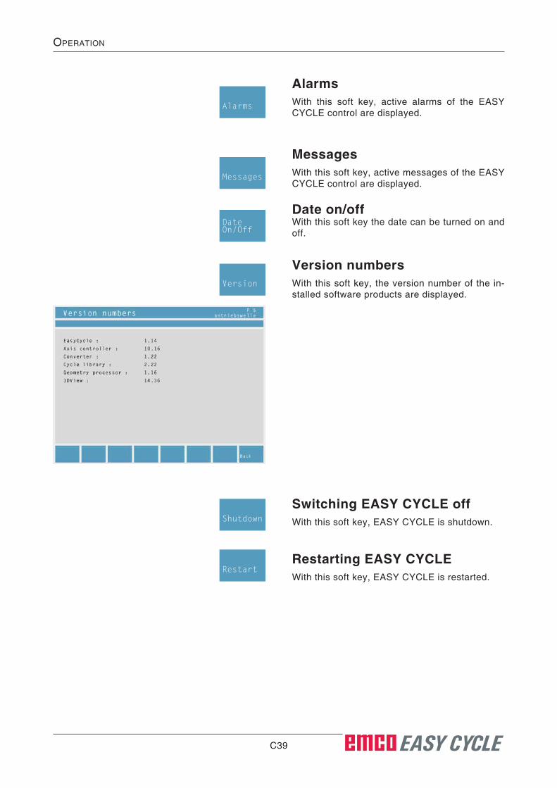
3 To use a fixed IP address, DHCP has to be turned off and the corresponding values for IP address, subnet mask, gateway and DNS servers have to be listed.
4 The changes are activated in the controller immediately by pressing the soft key "Accept.
Accept
FTP connection1 The connection to EASY CYCLE can be
established with all popular FTP-clients (eg. FileZilla):
Username: ecuser Password:emco
2 Once the connection is established, you are in the directory / linctrl / easycycle.m (milling machine) respectively / linctrl / easycycle.t (lathe).
3 In the subdirectory "data" you will find both files with the tool data: toolmill.tab and tool-mill.tech (milling machine) or toolturn.tab and toolturn.tech (lathe).
4 In the subdirectory "prog" you will find all pro-grams, contours and hole patterns. To be rec-ognized by the control system, all files have to have a name with exactly six digits and the file type pim (milling machine) respectively pit (lathe).
The program numbers are divided into the following areas:
• 000001-994999: NC-Program• 995001-995999: hole pattern• 996001-996999: contours (milling machine)• 998001-998999: contours (lathe)
Note:When transferring data via FTP, make sure that the machine side of the "position indi-cator" (main page) is displayed and no NC program is executed, only in this way can be guaranteed that only current data will be used.
C39 EASY CYCLE
OperatiOn
AlarmsWith this soft key, active alarms of the EASY CYCLE control are displayed.
Alarms
MessagesWith this soft key, active messages of the EASY CYCLE control are displayed.
Date on/offWith this soft key the date can be turned on and off.
Messages
DateOn/Off
Version numbersWith this soft key, the version number of the in-stalled software products are displayed.
Version
Switching EASY CYCLE offWith this soft key, EASY CYCLE is shutdown.
Restarting EASY CYCLEWith this soft key, EASY CYCLE is restarted.
Shutdown
Restart

C40 EASY CYCLE
OperatiOn
ReferenceThis soft key enables you to set a reference point.Refer-
ence
Referencing the X/Z axisWith this soft key, the X/Z axis is referenced.Ref.
Z-axisRef.X-axis
Referencing all With this soft key, the X and Z axis are referenced.Ref.
all
Reference position / path to goWith this soft key, you can either have the refer-ence position without offset (tool, datum shift, ...) or the path to go from the current tool position to the target position displayed.
Ref Posdistance

C41 EASY CYCLE
OperatiOn
Block scanPress the soft key Programs to enter the program management and select a program.
With block scan, cycles can be skipped during program run.
Skipping cycles in the block scan• Move the highlight to the required program.
• Press the soft key.
• Press the "ESC“ key.
• Press the soft key.
Programs
Select
ESC
• Use the cursor keys to select the cycle from which the NC program shall continue.
• Press the soft key. Wait until the EASY CYCLE control has calculated the remaining program. Press "NC-Start“ only after EASY CYCLE has prompted you to do so in the status display. The skipped cycles will not be carried out.
Start
Blockscan

C42
D1 EASY CYCLE
prOgramming
D: Programming
CyclesOverview CyclesThe cycle groups including the defined cycles of the EASY CYCLE are listed below.
Longitudinal turning• Turning 1• Turning 2
Facing• Facing 1• Facing 2
Thread cutting• Thread cutting 1• Thread cutting 2• Thread cutting 3• Multiple gear thread
Grooving• Grooving 1• Grooving 2• Grooving 3• Grooving 4 • Cut-off
Contour turning• Contour turning
Bore• Drilling• Tapping
Positioning• Positioning
Grooving
Threadcutting
Facing
Longturning
Position
Bore
Contourturning

D2 EASY CYCLE
prOgramming
Taper turning• Taper 1• Taper 2• Taper 3
Radius turning• Radius turning
ISO Edit• Input of the DIN/ISO code
Coordinate transformation• Absolute zero offset• Incremental zero offset• Cancel zero offset
Call subprogram• Select a subprogram
Taperturning
Radiusturning
Isoedit
Coord.trans.
Callsubprog.
D3 EASY CYCLE
prOgramming
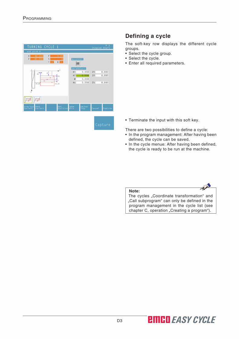
Defining a cycleThe soft-key row displays the different cycle groups.• Select the cycle group.• Select the cycle.• Enter all required parameters.
• Terminate the input with this soft key.
There are two possibilities to define a cycle:• In the program management: After having been
defined, the cycle can be saved.• In the cycle menue: After having been defined,
the cycle is ready to be run at the machine.
Note:The cycles „Coordinate transformation“ and „Call subprogram“ can only be defined in the program management in the cycle list (see chapter C, operation „Creating a program“).
Capture

D4 EASY CYCLE
prOgramming
Geom-etry
Previousvariant
Nextvariant
Input of geometry data
Actual value
The symbols display the additionally available cycles of the respective cycle group.
Input box for geometry data: selection of the input boxes via the operating panel at the EASY CYCLE or by means of the PC keyboard.
Selection boxes: can either be selected with the cursor keys or by pressing the selection key, or can be switched with the key sequence "Strg + F".
Soft key for the input of tech-nology data.
Input of geometry data
Safety distanceIn order to avoid collisions with the workpiece during cycles, you can determine an approach point that will be traversed prior to the cycle start-ing point.
The safety distance Xs, Zs defines the position of this approach point in relation to the cycle start-ing point.
The safety distance Xs is always programmed as radius value.Safety distance Xs, Zs
Safety distance Xs, Zs
Note:Use these soft keys to select additional cycles in the actual cycle group.
Z
X
X
Z
Xi, ZiXf, Zf
Xs, Zs
Soft key for copying the current actual values (X, Z) in the marked input box.

D5 EASY CYCLE
prOgramming
Techno-logy
Spindle speed [rpm]The spindle speed is entered under the parameter S. You can programm different spindle speeds for the roughing and the finishing pass.
Direction of rotation of spindleclockwise / counter-clockwise
Constant spindle speed [rpm] / cutting speed [m/min]Set the constant spindle speed with RPM, the constant cutting speed with CSS and the maxi-mum spindle speed with Smax.
Feed rate [mm/rpm]The feed rate is entered under the parameter F.You can programm different feed rates for the roughing and the finishing pass.
ToolEnter the respective tool and the tool correction data under T and D (for every tool, several cor-rection values are possible).In working-off cycles (e.g. longitudinal turning), you can program different tools for the roughing and finishing pass (see chapter E, tool measure-ment). Use the soft key "Tool table“ to read or edit the tool data. A tool can be accepted in the cycle automatically. When changing the tool, the feed and speed (rpm) are taken from the tool table into the corresponding fields.
CSS
Input of technology data
The symbols display the additionally available cycles of the corresponding cycle group.
Complete machiningDefine a tool for roughing and finishing. Both cycles will be carried out one after the other with the respective settings and tools.
You can select different feed rates, spindle speeds and tools for both roughing and finishing.For already defined tools, after being selected, the corresponding spindle speeds and feed rates will be entered as changeable suggestion.When different tools have been defined for rough-ing and finishing, the toolholder will automatically traverse a tool changing point.
RoughingSelect the tool T0 as roughing tool. Then the rough cycle will not be carried out.A defined finishing clearance will be considered during roughing.
FinishingSelect the tool T0 as finishing tool. Then the fin-ishing cycle will not be carried out.
Coolantturning the coolant on / off
Current actual value
Selection boxes: can either be selected with the cursor keys or by pressing the selection key, or can be switched with the key sequence "Strg + F".
Soft key for the input of geom-etry data.
Coolant on / off
Shortcut to the tool data.
Input box for geometry data: selection of the input boxes via the operating panel at the EASY CYCLE or by means of the PC keyboard.
D6 EASY CYCLE
prOgramming
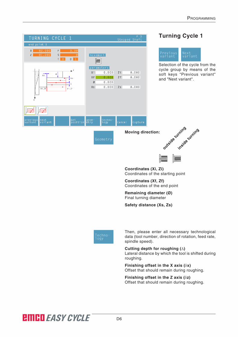
Turning Cycle 1
Coordinates (Xi, Zi)Coordinates of the starting point
Coordinates (Xf, Zf)Coordinates of the end point
Remaining diameter (ø)Final turning diameter
Safety distance (Xs, Zs)
Selection of the cycle from the cycle group by means of the soft keys "Previous variant" and "Next variant".
Then, please enter all necessary technological data (tool number, direction of rotation, feed rate, spindle speed).
Cutting depth for roughing (∆)Lateral distance by which the tool is shifted during roughing.
Finishing offset in the X axis (δx)Offset that should remain during roughing.
Finishing offset in the Z axis (δz)Offset that should remain during roughing.
Moving direction:
outsid
e turn
ing
insid
e turn
ing
Previousvariant
Nextvariant
Geometry
Techno-logy

D7 EASY CYCLE
prOgramming
Z
X1
2
4
3
5
W
∆
ø
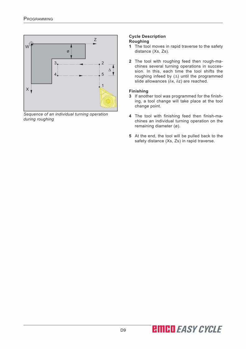
Cycle DescriptionRoughing1 The tool moves in rapid traverse to the safety
distance (Xs, Zs).
2 The tool with roughing feed then rough-ma-chines several turning operations in succes-sion. In this, each time the tool shifts the roughing infeed by (∆) until the programmed slide allowances (δx, δz) are reached.
Finishing3 If another tool was programmed for the finish-
ing, a tool change will take place at the tool change point.
4 The tool with finishing feed then finish-ma-chines an individual turning operation on the remaining diameter (ø).
5 At the end, the tool will be pulled back to the safety distance (Xs, Zs) in rapid traverse.
Sequence of an individual turning operation during roughing

D8 EASY CYCLE
prOgramming
Turning Cycle 2
Coordinates (Xi, Zi)Coordinates of the starting point
Coordinates (Xf, Zf)Coordinates of the end point
Remaining diameter (ø)Final turning diameter
Safety distance (Xs, Zs)
Selection of the cycle from the cycle group by means of the soft keys „Previous variant“ and „Next variant“.
Then, please enter all necessary technological data (tool number, direction of rotation, feed rate, spindle speed).
Cutting depth for roughing (∆)Lateral distance by which the tool is shifted during roughing.
Finishing offset in the X axis (δx)Offset that should remain during roughing.
Finishing offset in the Z axis (δz)Offset that should remain during roughing.
Moving direction:
outsid
e turn
ing
insid
e turn
ing
Corner rounding:
shar
p-edged
rounded
cham
fere
d at 45
°
Geometry
Techno-logy
Previousvariant
Nextvariant
D9 EASY CYCLE
prOgramming
Z
X1
2
4
3
5
W
∆
ø
Cycle DescriptionRoughing1 The tool moves in rapid traverse to the safety
distance (Xs, Zs).
2 The tool with roughing feed then rough-ma-chines several turning operations in succes-sion. In this, each time the tool shifts the roughing infeed by (∆) until the programmed slide allowances (δx, δz) are reached.
Finishing3 If another tool was programmed for the finish-
ing, a tool change will take place at the tool change point.
4 The tool with finishing feed then finish-ma-chines an individual turning operation on the remaining diameter (ø).
5 At the end, the tool will be pulled back to the safety distance (Xs, Zs) in rapid traverse.
Sequence of an individual turning operation during roughing
D10 EASY CYCLE
prOgramming
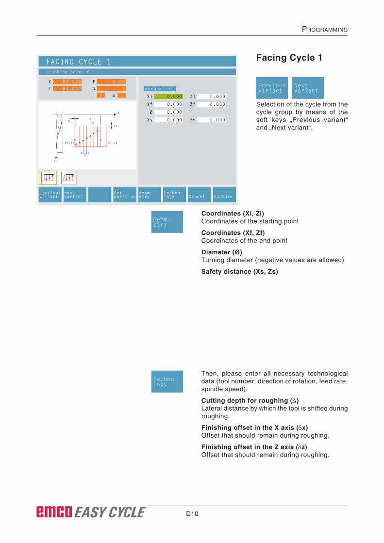
Facing Cycle 1
Coordinates (Xi, Zi)Coordinates of the starting point
Coordinates (Xf, Zf)Coordinates of the end point
Diameter (ø)Turning diameter (negative values are allowed)
Safety distance (Xs, Zs)
Selection of the cycle from the cycle group by means of the soft keys „Previous variant“ and „Next variant“.
Then, please enter all necessary technological data (tool number, direction of rotation, feed rate, spindle speed).
Cutting depth for roughing (∆)Lateral distance by which the tool is shifted during roughing.
Finishing offset in the X axis (δx)Offset that should remain during roughing.
Finishing offset in the Z axis (δz)Offset that should remain during roughing.
Geom-etry
Previousvariant
Nextvariant
Techno-logy

D11 EASY CYCLE
prOgramming
Z
X
2
3 4
1
5
Wø
∆
Cycle DescriptionRoughing1 The tool moves in rapid traverse to the safety
distance (Xs, Zs).
2 The tool with roughing feed then rough-ma-chines several facing operations in succes-sion. In this, each time the tool shifts the roughing infeed by (∆) until the programmed slide allowances (δx, δz) are reached.
Finishing3 If another tool was programmed for the finish-
ing, a tool change will take place at the tool change point.
4 The tool with finishing feed then finish-ma-chines an individual facing operation on the remaining diameter (ø).
5 At the end, the tool will be pulled back to the safety distance (Xs, Zs) in rapid traverse.
Sequence of an individual facing operation during roughing

D12 EASY CYCLE
prOgramming
Facing Cycle 2
Coordinates (Xi, Zi)Coordinates of the starting point
Coordinates (Xf, Zf)Coordinates of the end point
Diameter (ø)Turning diameter (negative values are allowed)
Corner rounding:
Selection of the cycle from the cycle group by means of the soft keys „Previous variant“ and „Next variant“.
Then, please enter all necessary technological data (tool number, direction of rotation, feed rate, spindle speed).
Cutting depth for roughing (∆)Lateral distance by which the tool is shifted during roughing.
Finishing offset in the X axis (δx)Offset that should remain during roughing.
Finishing offset in the Z axis (δz)Offset that should remain during roughing.
shar
p-edged
rounded
cham
fere
d at 45
°
Safety distance (Xs, Zs)
Geometry
Previousvariant
Nextvariant
Techno-logy

D13 EASY CYCLE
prOgramming
Z
X
2
3 4
1
5
Wø
∆
Cycle DescriptionRoughing1 The tool moves in rapid traverse to the safety
distance (Xs, Zs).
2 The tool with roughing feed then rough-ma-chines several facing operations in succes-sion. In this, each time the tool shifts the roughing infeed by (∆) until the programmed slide allowances (δx, δz) are reached.
Finishing3 If another tool was programmed for the finish-
ing, a tool change will take place at the tool change point.
4 The tool with finishing feed then finish-ma-chines an individual facing operation on the remaining diameter (ø).
5 At the end, the tool will be pulled back to the safety distance (Xs, Zs) in rapid traverse.
Sequence of an individual facing operation during roughing

D14 EASY CYCLE
prOgramming
Thread Cutting 1
Selection of the cycle from the cycle group by means of the soft keys „Previous variant“ and „Next variant“.
U.N.F. Fine pitch unified American th-read
U.N.C. Normal pitch unified American thread
B.S.F. Fine pitch Withworth thread
B.S.W. (W) Normal pitch Withworth th-read
M (S.I.F.) Fine pitch metric thread
M (S.I.) Normal pitch metric thread
Free pitch thread
Thread diameter (ø)
Thread pitch (P)
Depth of thread (H)
Thread runout (σ)
Starting angle (W)Position of the spindle
Coordinates (Xi, Zi)Coordinates of the starting point of the thread
Coordinate (Zf)Coordinate of the end point of the thread
Thread typeYou can choose among the following standardi-zed thread types:
Moving direction:
outsid
e thre
ad
insid
e thre
ad
Safety distance (Xs, Zs)
not act
ive
activ
e
Note:With the thread type „free pitch thread“ the thread pitch P and the thread depth H can be freely chosen.With all other thread types the thread pitch P and the thread depth H will be autoMatically preset with standardized values after input of the thread diameter ø.In case a thread diameter is entered which is not standardized, EASY CYCLE will automati-cally set the next standardized diameter.
This cycle enables to machine longitudinal threads (inside and outside).
Previousvariant
Nextvariant
Geom-etry
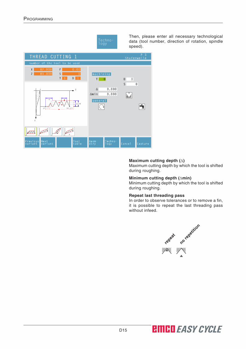
D15 EASY CYCLE
prOgramming
Then, please enter all necessary technological data (tool number, direction of rotation, spindle speed).
Maximum cutting depth (∆)Maximum cutting depth by which the tool is shifted during roughing.
Minimum cutting depth (∆min)Minimum cutting depth by which the tool is shifted during roughing.
Repeat last threading passIn order to observe tolerances or to remove a fin, it is possible to repeat the last threading pass without infeed.
repea
t
no repet
ition
Techno-logy

D16 EASY CYCLE
prOgramming
Cycle Description1 According to the spindle's chosen direction of
rotation, a right or left thread will be turned.
2 The tool moves in rapid traverse to the safety distance (Xs, Zs).
3 The thread will be cut in several radial groov-ing operations until the thread depth (H) is reached. The infeed (∆) of the individual op-erations depends on which operation it is (∆, ∆√2, ∆√3, ∆√4, ...). If a decreasing infeed is lower than the minimum infeed (∆min), at least (∆min) will be fed in.
4 If selected - the tool repeats the last threading operation.
5 At the end, the tool will be pulled back to the safety distance (Xs, Zs) in rapid traverse.

D17 EASY CYCLE
prOgramming

D18 EASY CYCLE
prOgramming
Thread Cutting 2
Selection of the cycle from the cycle group by means of the soft keys „Previous variant“ and „Next variant“.
U.N.F. Fine pitch unified American th-read
U.N.C. Normal pitch unified American thread
B.S.F. Fine pitch Withworth thread
B.S.W. (W) Normal pitch Withworth th-read
M (S.I.F.) Fine pitch metric thread
M (S.I.) Normal pitch metric thread
Free pitch thread
Thread diameter (ø)
Thread pitch (P)+ pos. arithmetic sign: dimension in direction of the thread- neg. arithmetic sign: dimension in direction of the Z axis
Depth of thread (H)
Thread runout (σ)
Starting angle (W)Position of the spindle
Coordinates (Xi, Zi)Coordinates of the starting point of the thread
Coordinates (Xf, Zf)Coordinates of the end point of the thread
Thread typeYou can choose among the following standardi-zed thread types:
Moving direction:
outsid
e thre
ad
insid
e thre
ad
Safety distance (Xs, Zs)
not act
ive
activ
e
This cycle enables to machine tapered threads (inside and outside).
Previousvariant
Nextvariant
Geom-etry
Note:With the thread type „free pitch thread“ the thread pitch P and the thread depth H can be freely chosen.With all other thread types the thread pitch P and the thread depth H will be autoMatically preset with standardized values after input of the thread diameter ø.In case a thread diameter is entered which is not standardized, EASY CYCLE will automati-cally set the next standardized diameter.

D19 EASY CYCLE
prOgramming
Then, please enter all necessary technological data (tool number, direction of rotation, spindle speed).
Maximum cutting depth (∆)Maximum cutting depth by which the tool is shifted during roughing.
Minimum cutting depth (∆min)Minimum cutting depth by which the tool is shifted during roughing.
Angle of infeed (α)Half flank angle (normally 30°)
Decreasing or constant cutting depth
repea
t
no repet
ition
c o n s t an t
infe
ed decre
asing in
-
feed
Types of infeed:
centric in
-
feed in
feed
alo
ng the
flank in
feed in
zig
-
zag
Repeat last threading passIn order to observe tolerances or to remove a fin, it is possible to repeat the last threading pass without infeed.
Techno-logy

D20 EASY CYCLE
prOgramming
Cycle Description1 According to the spindle's chosen direction of
rotation, a right or left thread will be turned.
2 The tool moves in rapid traverse to the safety distance (Xs, Zs).
3 The thread will be cut in several operations until the thread depth (H) is reached.
The icon-selected infeed is carried out: • at a constant infeed each time of (∆),
• at an infeed decreasing by (∆, ∆√2, ∆√3, ∆√4, ...). If a decreasing infeed is lower than the minimum infeed (∆min), at least (∆min) will be fed in.
The icon-selected infeed type will be taken into account.
4 If selected - the tool repeats the last threading operation.
5 At the end, the tool will be pulled back to the safety distance (Xs, Zs) in rapid traverse.

D21 EASY CYCLE
prOgramming

D22 EASY CYCLE
prOgramming
Thread Cutting 3
Selection of the cycle from the cycle group by means of the soft keys „Previous variant“ and „Next variant“.
This cycle enables to machine face threads.
Coordinates (Xi, Zi)Coordinates of the starting point of the thread
Coordinates (Xf, Zf)Coordinates of the end point of the thread
Thread pitch (P)+ pos. arithmetic sign: dimension in direction of the thread- neg. arithmetic sign: dimension in direction of the Z axis
Depth of thread (H)
Thread runout (σ)
Starting angle (W)Position of the spindle
Safety distance (Xs, Zs)
not act
ive
activ
e
Previousvariant
Nextvariant
Geom-etry
Note:With the thread type „free pitch thread“ the thread pitch P and the thread depth H can be freely chosen.With all other thread types the thread pitch P and the thread depth H will be autoMatically preset with standardized values after input of the thread diameter ø.In case a thread diameter is entered which is not standardized, EASY CYCLE will automati-cally set the next standardized diameter.
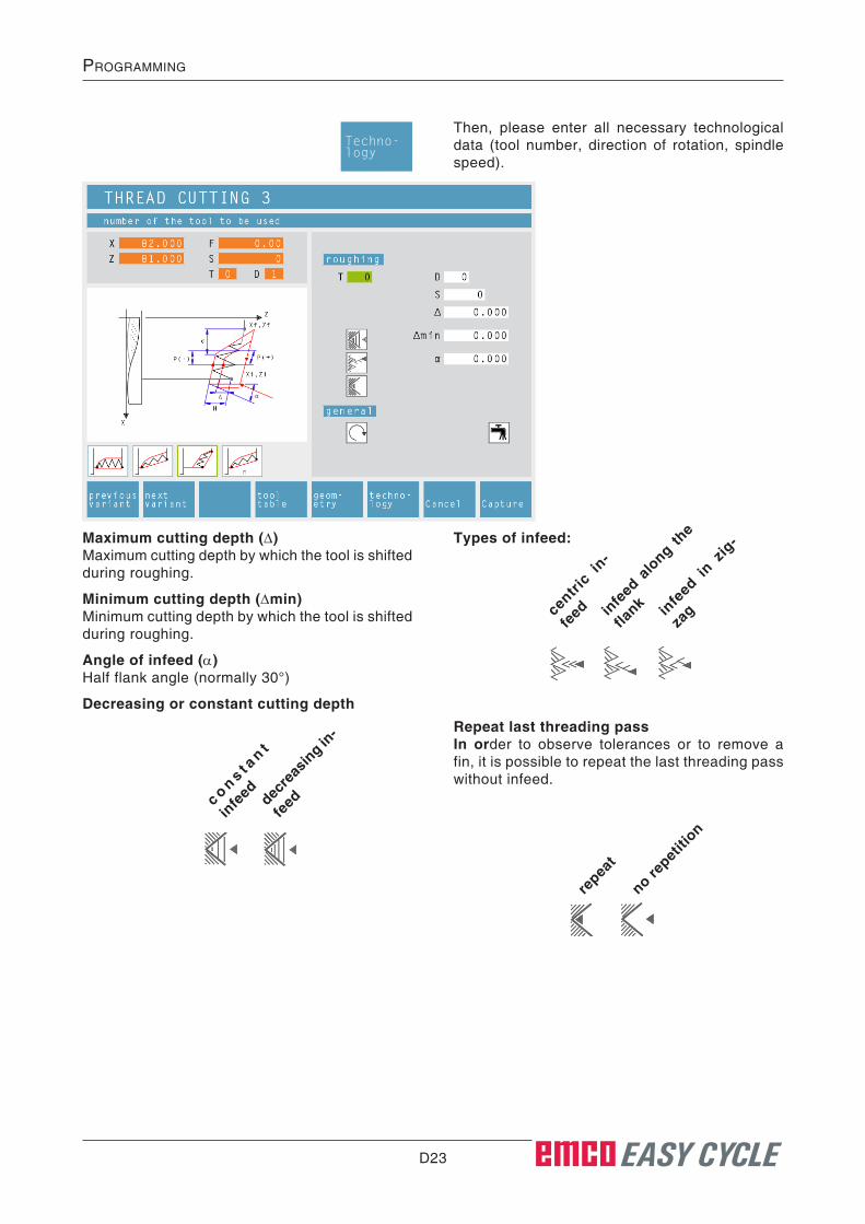
D23 EASY CYCLE
prOgramming
Then, please enter all necessary technological data (tool number, direction of rotation, spindle speed).
Maximum cutting depth (∆)Maximum cutting depth by which the tool is shifted during roughing.
Minimum cutting depth (∆min)Minimum cutting depth by which the tool is shifted during roughing.
Angle of infeed (α)Half flank angle (normally 30°)
Decreasing or constant cutting depth
repea
t
no repet
ition
c o n s t an t
infe
ed decre
asing in
-
feed
Types of infeed:
centric in
-
feed in
feed
alo
ng the
flank in
feed in
zig
-
zag
Repeat last threading passIn order to observe tolerances or to remove a fin, it is possible to repeat the last threading pass without infeed.
Techno-logy
D24 EASY CYCLE
prOgramming
Cycle Description1 According to the spindle's chosen direction of
rotation, a right or left thread will be turned.
2 The tool moves in rapid traverse to the safety distance (Xs, Zs).
3 The thread will be cut in several operations until the thread depth (H) is reached.
The icon-selected infeed is carried out: • at a constant infeed each time of (∆),
• at an infeed decreasing by (∆, ∆√2, ∆√3, ∆√4, ...). If a decreasing infeed is lower than the minimum infeed (∆min), at least (∆min) will be fed in.
The icon-selected infeed type will be taken into account.
4 If selected - the tool repeats the last threading operation.
5 At the end, the tool will be pulled back to the safety distance (Xs, Zs) in rapid traverse.

D25 EASY CYCLE
prOgramming

D26 EASY CYCLE
prOgramming
Multiple Gear Thread
Selection of the cycle from the cycle group by means of the soft keys „Previous variant“ and „Next variant“.
U.N.F. Fine pitch unified American th-read
U.N.C. Normal pitch unified American thread
B.S.F. Fine pitch Withworth thread
B.S.W. (W) Normal pitch Withworth th-read
M (S.I.F.) Fine pitch metric thread
M (S.I.) Normal pitch metric thread
Free pitch thread
Thread diameter (ø)
Thread pitch (P)+ pos. arithmetic sign: dimension in direction of the thread- neg. arithmetic sign: dimension in direction of the Z axis
Depth of thread (H)
Number of threads (N)
Thread runout (σ)
Starting angle (W)Position of the spindle
Coordinates (Xi, Zi)Coordinates of the starting point of the thread
Coordinates (Xf, Zf)Coordinates of the end point of the thread
Thread typeYou can choose among the following standardi-zed thread types:
Moving direction:
outsid
e thre
ad
insid
e thre
ad
Safety distance (Xs, Zs)
not act
ive
activ
e
This cycle enables to machine outside, inside and tapered threads with any number of threads.
Previousvariant
Nextvariant
Geom-etry
Note:With the thread type „free pitch thread“ the thread pitch P and the thread depth H can be freely chosen.With all other thread types the thread pitch P and the thread depth H will be autoMatically preset with standardized values after input of the thread diameter ø.In case a thread diameter is entered which is not standardized, EASY CYCLE will automati-cally set the next standardized diameter.

D27 EASY CYCLE
prOgramming
Then, please enter all necessary technological data (tool number, direction of rotation, spindle speed).
Maximum cutting depth (∆)Maximum cutting depth by which the tool is shifted during roughing.
Minimum cutting depth (∆min)Minimum cutting depth by which the tool is shifted during roughing.
Angle of infeed (α)Half flank angle (normally 30°)
Decreasing or constant cutting depth
repea
t
no repet
ition
c o n s t an t
infe
ed decre
asing in
-
feed
Types of infeed:
centric in
-
feed in
feed
alo
ng the
flank in
feed in
zig
-
zag
Repeat last threading passIn order to observe tolerances or to remove a fin, it is possible to repeat the last threading pass without infeed.
Techno-logy

D28 EASY CYCLE
prOgramming
Cycle Description1 According to the spindle's chosen direction of
rotation, a right or left thread will be turned.
2 The tool moves in rapid traverse to the safety distance (Xs, Zs).
3 The thread will be cut in several operations until the thread depth (H) is reached.
The icon-selected infeed is carried out: • at a constant infeed each time of (∆),
• at an infeed decreasing by (∆, ∆√2, ∆√3, ∆√4, ...). If a decreasing infeed is lower than the minimum infeed (∆min), at least (∆min) will be fed in.
The icon-selected infeed type will be taken into account.
4 If selected - the tool repeats the last threading operation.
5 At the end, the tool will be pulled back to the safety distance (Xs, Zs) in rapid traverse.

D29 EASY CYCLE
prOgramming

D30 EASY CYCLE
prOgramming
Coordinates (Xi, Zi)Coordinates of the starting point
Coordinates (Xf, Zf)Coordinates of the end point
Remaining diameter (ø)Final turning diameter
Number of grooves (N)
Distance between grooves (I)Distance between two grooves (from Xi1Zi1 - Xi-2Zi2). For one groove only please enter I=0.
Safety distance (Xs, Zs)
Then, please enter all necessary technological data (tool number, direction of rotation, feed rate, spindle speed).
Cutting depth for roughing (∆)Lateral distance by which the tool is shifted during roughing.
Dwell time (t)
Finishing offset (δ)Offset that should remain during roughing.
Grooving Cycle 1
Moving direction:
outsid
e turn
ing
insid
e turn
ing
Selection of the cycle from the cycle group by means of the soft keys „Previous variant“ and „Next variant“.
This cycle enables to machine a straight, radial groove.
Note:The groove has to be the same size or must be larger than the tool width.It is absolutely necessary to enter the tool width (B) during tool calibration.
The cutting depth for roughing ∆ should be a little bit smaller than the tool width.
Previousvariant
Nextvariant
Techno-logy
Geom-etry

D31 EASY CYCLE
prOgramming
Z
X
Xs, Zs
Wø ∆
δ
Z
X
Xs, Zs
Wø
Cycle DescriptionRoughing1 The tool moves in rapid traverse to the safety
distance (Xs, Zs).
2 The tool with roughing feed then rough-ma-chines several turning operations in succes-sion. In this, each time the tool shifts the roughing infeed by (∆) until the programmed slide allowance (δ) is reached and lingers there for (t) - if entered.
Sequence of grooving operations during roughing
Sequence of grooving operations during finishing
Finishing3 If another tool was programmed for the finish-
ing, a tool change will take place at the tool change point.
4 The tool with finishing feed then finish-ma-chines an individual grooving operation on the remaining diameter (ø).
5 At the end, the tool will be pulled back to the safety distance (Xs, Zs) in rapid traverse.

D32 EASY CYCLE
prOgramming
Coordinates (Xi, Zi)Coordinates of the starting point
Coordinates (Xf, Zf)Coordinates of the end point
Depth of groove (R)Z coordinate of the groove
Number of grooves (N)
Distance between grooves (I)Distance between two grooves (from Xi1Zi1 - Xi-2Zi2). For one groove only please enter I=0.
Safety distance (Xs, Zs)
Grooving Cycle 2
Then, please enter all necessary technological data (tool number, direction of rotation, feed rate, spindle speed).
Cutting depth for roughing (∆)Lateral distance by which the tool is shifted during roughing.
Dwell time (t)in seconds
Finishing offset (δ)Offset that should remain during roughing.v
Selection of the cycle from the cycle group by means of the soft keys „Previous variant“ and „Next variant“.
This cycle enables to machine a straight, axial groove.
Note:The groove has to be the same size or must be larger than the tool width.It is absolutely necessary to enter the tool width (B) during tool calibration.
The cutting depth for roughing ∆ should be a little bit smaller than the tool width.
Previousvariant
Nextvariant
Techno-logy
Geom-etry

D33 EASY CYCLE
prOgramming
δ
∆
X
Z
R
Xs, Zs
W
X
Z
R
Xs, Zs
W
Cycle DescriptionRoughing1 The tool moves in rapid traverse to the safety
distance (Xs, Zs).
2 The tool with roughing feed then rough-ma-chines several grooving operations in suc-cession. In this, each time the tool shifts the roughing infeed by (∆) until the programmed slide allowance (δ) is reached and lingers there for (t) - if entered.
Sequence of grooving operations during roughing
Sequence of grooving operations during finishing
Finishing3 If another tool was programmed for the finish-
ing, a tool change will take place at the tool change point.
4 The tool with finishing feed then finish-ma-chines an individual grooving operation on the remaining diameter (ø).
5 At the end, the tool will be pulled back to the safety distance (Xs, Zs) in rapid traverse.
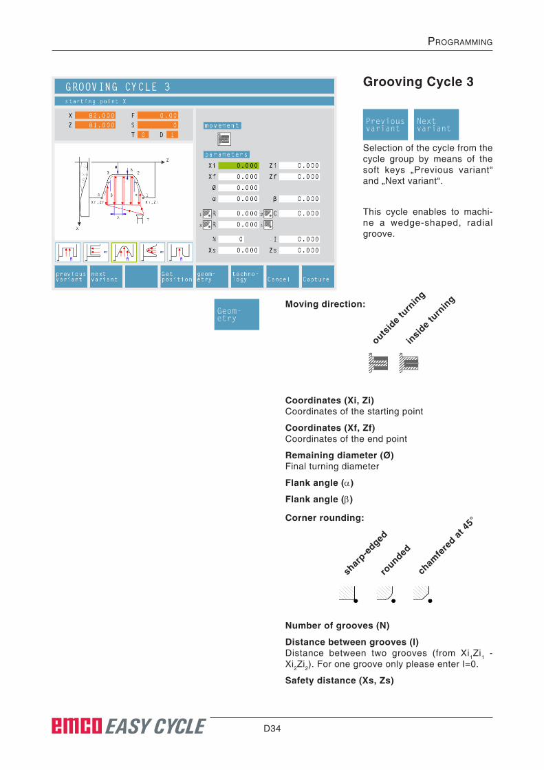
D34 EASY CYCLE
prOgramming
Grooving Cycle 3
Selection of the cycle from the cycle group by means of the soft keys „Previous variant“ and „Next variant“.
This cycle enables to machi-ne a wedge-shaped, radial groove.
Coordinates (Xi, Zi)Coordinates of the starting point
Coordinates (Xf, Zf)Coordinates of the end point
Remaining diameter (ø)Final turning diameter
Flank angle (α)
Flank angle (β)
Number of grooves (N)
Distance between grooves (I)Distance between two grooves (from Xi1Zi1 - Xi2Zi2). For one groove only please enter I=0.
Safety distance (Xs, Zs)
Moving direction:
outsid
e turn
ing
insid
e turn
ing
Corner rounding:
shar
p-edged
rounded
cham
fere
d at 45
°
Previousvariant
Nextvariant
Geom-etry

D35 EASY CYCLE
prOgramming
Then, please enter all necessary technological data (tool number, direction of rotation, feed rate, spindle speed).
Cutting depth for roughing (∆)Lateral distance by which the tool is shifted during roughing.
Finishing offset (δ)Offset that should remain during roughing.
Techno-logy
Note:The groove has to be the same size or must be larger than the tool width.It is absolutely necessary to enter the tool width (B) during tool calibration.
The cutting depth for roughing ∆ should be a little bit smaller than the tool width.
Feed settingRoughing feed in mm/revolution
Feed settingRoughing feed in mm/min

D36 EASY CYCLE
prOgramming
Cycle DescriptionRoughing1 The tool moves in rapid traverse to the safety
distance (Xs, Zs).
2 The tool with roughing feed then rough-ma-chines several grooving operations in suc-cession. In this, each time the tool shifts the roughing infeed by (∆), taking into account the thread angles(α, β) until the programmed slide allowance (δ) is reached and lingers there for (t) - if entered.
Finishing3 If another tool was programmed for the finish-
ing, a tool change will take place at the tool change point.
4 The tool with finishing feed then finish-ma-chines an individual grooving operation on the remaining diameter (ø).
5 At the end, the tool will be pulled back to the safety distance (Xs, Zs) in rapid traverse.

D37 EASY CYCLE
prOgramming

D38 EASY CYCLE
prOgramming
Grooving Cycle 4
Selection of the cycle from the cycle group by means of the soft keys „Previous variant“ and „Next variant“.
This cycle enables to machine a wedge-shaped, axial groo-ve.
Corner rounding:
shar
p-edged
rounded
cham
fere
d at 45
°
Coordinates (Xi, Zi)Coordinates of the starting point
Coordinates (Xf, Zf)Coordinates of the end point
Depth of groove (R)Z coordinate of the groove
Flank angle (α)
Flank angle (β)
Number of grooves (N)
Distance between grooves (I)Distance between two grooves (from Xi1Zi1 - Xi2Zi2). For one groove only please enter I=0.
Safety distance (Xs, Zs)
Previousvariant
Nextvariant
Geom-etry

D39 EASY CYCLE
prOgramming
Then, please enter all necessary technological data (tool number, direction of rotation, feed rate, spindle speed).
Cutting depth for roughing (∆)Lateral distance by which the tool is shifted during roughing.
Finishing offset (δ)Offset that should remain during roughing.
Techno-logy
Note:The groove has to be the same size or must be larger than the tool width.It is absolutely necessary to enter the tool width (B) during tool calibration.
The cutting depth for roughing ∆ should be a little bit smaller than the tool width.
Feed settingRoughing feed in mm/revolution
Feed settingRoughing feed in mm/min

D40 EASY CYCLE
prOgramming
Cycle DescriptionRoughing1 The tool moves in rapid traverse to the safety
distance (Xs, Zs).
2 The tool with roughing feed then rough-ma-chines several grooving operations in suc-cession. In this, each time the tool shifts the roughing infeed by (∆), taking into account the thread angles(α, β) until the programmed slide allowance (δ) is reached and lingers there for (t) - if entered.
Finishing3 If another tool was programmed for the finish-
ing, a tool change will take place at the tool change point.
4 The tool with finishing feed then finish-ma-chines an individual grooving operation on the remaining diameter (ø).
5 At the end, the tool will be pulled back to the safety distance (Xs, Zs) in rapid traverse.

D41 EASY CYCLE
prOgramming

D42 EASY CYCLE
prOgramming
Cut-Off Cycle
Selection of the cycle from the cycle group by means of the soft keys „Previous variant“ and „Next variant“.
This cycle enables to quickly cut off turning components.
Note:Select øf = 0 to cut off workpieces.It is absolutely necessary to enter the tool width (B) during tool calibration.
Corner rounding:
shar
p-edged
rounded
cham
fere
d at 45
°
Coordinates (Xi, Zi)Coordinates of the starting point
Diameter (øf)Final diameter
Safety distance (Xs, Zs)
Then, please enter all necessary technological data (tool number, direction of rotation, feed rate, spindle speed).
Feed rate for cutting-off cycle (Fr)Feed rate at which the tool moves from the inter-mediate diameter to the final diameter. In doing so, the feed rate F is gradually adjusted to the feed rate Fr.
Diameter (ør)Intermediate diameter
Previousvariant
Nextvariant
Techno-logy
Geom-etry

D43 EASY CYCLE
prOgramming
Z
X
Xs, Zs
Wøf
F
Fr
ør
Cycle Description1 The tool moves in rapid traverse to the safety
distance (Xs, Zs).
2 Then the tool with feed (F) grooves to the intermediate diameter (ør). The feed (F) is ad-justed step by step to the feed (Fr) until the end diameter (øf). If selected - bevels and radii will be created if needed by multiple grooving.
3 At the end, the tool will be pulled back to the safety distance (Xs, Zs) in rapid traverse.
Sequence of grooving operations during cutting
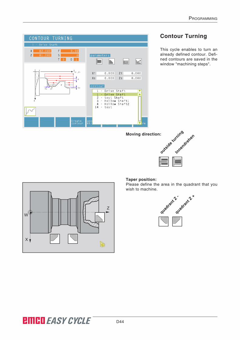
D44 EASY CYCLE
prOgramming
outsid
e turn
ing
Innen
drehen
Taper position:Please define the area in the quadrant that you wish to machine.
quadra
nt Z -
quadra
nt Z +
Z
X
W
Moving direction:
Contour Turning
This cycle enables to turn an already defined contour. Defi-ned contours are saved in the window "machining steps".

D45 EASY CYCLE
prOgramming
Cutting movement characteristic:
parall
el to
axis
parall
el to
conto
ur
Machining direction:
along th
e Z ax
is
along th
e X ax
is
By pressing this soft key, you get back to the con-tour management to define a new contour. When going back, the new contour will be automatically selected in the list.
Createcontour
Distance during 1st roughing pass (ε)Distance during parallel contour pre-roughingWith profile repetition, the material quantity that should be removed from the parent part must be defined.
Coordinates (Xi, Zi)Coordinates of the starting point
Safety distance (Xs, Zs)
ContourSelect a contour from the select list.
The softkey leads directly to contour ***editing***, in order to make changes to a contour here.See also Chapter C under "Contour Administra-tion".
ModifyContour

D46 EASY CYCLE
prOgramming
Then, please enter all necessary technological data (tool number, direction of rotation, feed rate, spindle speed).
Feed for infeed at relief cut (Fb)Feed rate during roughing parallel to axis
Cutting depth for roughing (∆)Lateral distance by which the tool is shifted during roughing.
Finishing offset either by tool shape or axis:
tool s
hape
axis
Finishing offset (δ)Offset that should remain during roughing.
Finishing offset in the X axis (δx)Offset that should remain during roughing.
Finishing offset in the Z axis (δz)Offset that should remain during roughing.
Finishing offset δ
Techno-logy

D47 EASY CYCLE
prOgramming
Cycle DescriptionRoughing1 The tool moves in rapid traverse to the safety
distance (Xs, Zs).
2 Then the tool with roughing feed moves to the first contour point and rough-machines axis/contour parallel several turning/facing op-erations in succession. In this, each time the tool shifts the roughing infeed by (∆) until the programmed slide allowances (δ or δx, δz) are reached. With axis-parallel pre-roughing, the grooving feed (Fb) of the tool must be defined in the pockets.
Finishing3 If another tool was programmed for the finish-
ing, a tool change will take place at the tool change point.
4 Then the tool with finishing infeed finish-ma-chines the contour in an individual turning operation.
5 At the end, the tool will be pulled back to the safety distance (Xs, Zs) in rapid traverse.
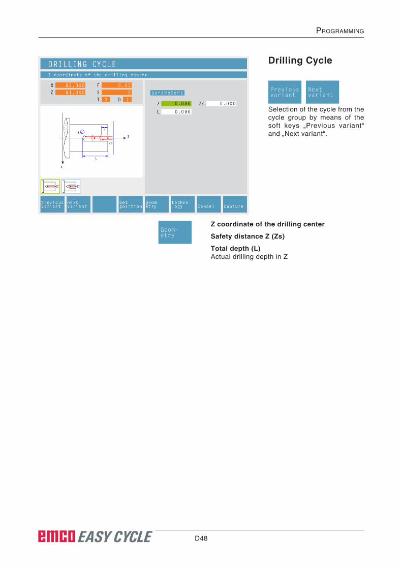
D48 EASY CYCLE
prOgramming
Drilling Cycle
Selection of the cycle from the cycle group by means of the soft keys „Previous variant“ and „Next variant“.
Z coordinate of the drilling center
Safety distance Z (Zs)
Total depth (L)Actual drilling depth in Z
Previousvariant
Nextvariant
Geom-etry

D49 EASY CYCLE
prOgramming
Then, please enter all necessary technological data (tool number, direction of rotation, feed rate, spindle speed).
Drilling stroke for 1st cutting depth (∆)1st depth of a drilling operation
Reducing factor for drilling stroke (K∆)Factor by which the subsequent drilling strokes will be reduced.
Minimum drilling stroke (∆min)Smallest cutting depth required (only for decrea-sing cutting depth)
Dwell time (t)in seconds
Techno-logy
Feed settingRoughing feed in mm/revolution
Feed settingRoughing feed in mm/min
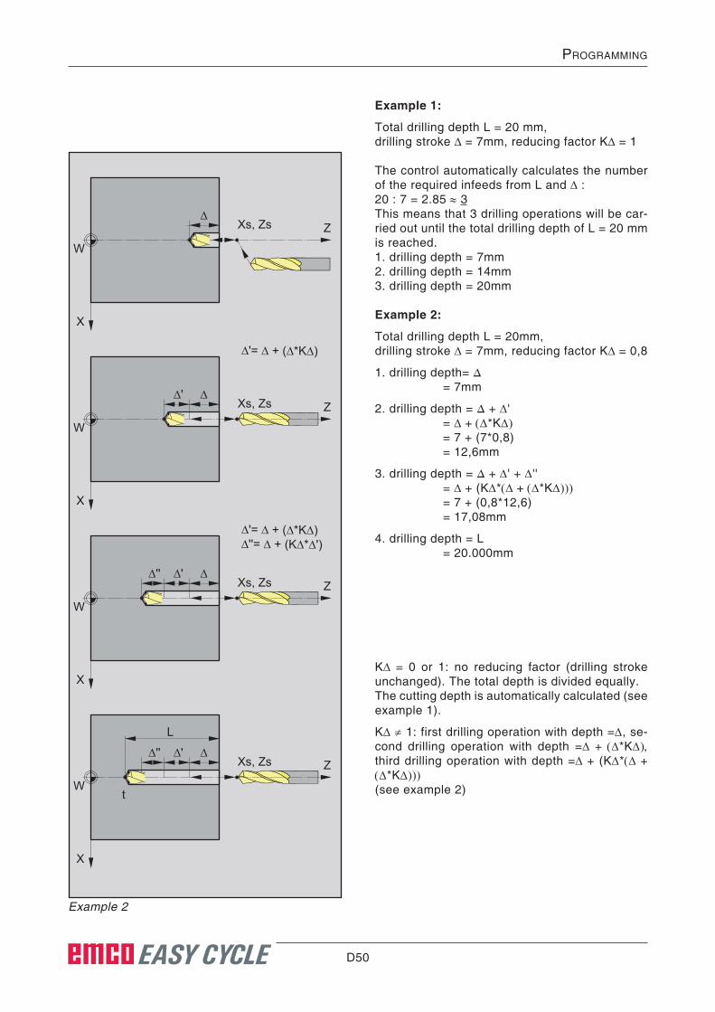
D50 EASY CYCLE
prOgramming
Example 1:
Total drilling depth L = 20 mm,drilling stroke ∆ = 7mm, reducing factor K∆ = 1
The control automatically calculates the number of the required infeeds from L and ∆ :20 : 7 = 2.85 ≈ 3This means that 3 drilling operations will be car-ried out until the total drilling depth of L = 20 mm is reached.1. drilling depth = 7mm2. drilling depth = 14mm3. drilling depth = 20mm
Example 2:
Total drilling depth L = 20mm,drilling stroke ∆ = 7mm, reducing factor K∆ = 0,8
1. drilling depth= ∆ = 7mm
2. drilling depth = ∆ + ∆' = ∆ + (∆*K∆) = 7 + (7*0,8) = 12,6mm
3. drilling depth = ∆ + ∆' + ∆'' = ∆ + (K∆*(∆ + (∆*K∆))) = 7 + (0,8*12,6) = 17,08mm
4. drilling depth = L = 20.000mm
K∆ = 0 or 1: no reducing factor (drilling stroke unchanged). The total depth is divided equally.The cutting depth is automatically calculated (see example 1).
K∆ ≠ 1: first drilling operation with depth =∆, se-cond drilling operation with depth =∆ + (∆*K∆), third drilling operation with depth =∆ + (K∆*(∆ + (∆*K∆)))(see example 2)
X
W
∆Xs, Zs Z
X
W
∆∆'Xs, Zs Z
∆'= ∆ + (∆*K∆)
X
W
∆∆'∆''Xs, Zs Z
∆'= ∆ + (∆*K∆)∆''= ∆ + (K∆*∆')
X
W
∆
L
∆'∆''
t
Xs, Zs Z
Example 2

D51 EASY CYCLE
prOgramming
Cycle Description1 The tool moves in rapid traverse to the safety
distance (Xs, Zs).
2 The tool with roughing feed then taps several tapping operations in succession. In this, the tool moves to the safety distance and then ad-vances by the calculated infeed in each case (see example). The tool dwells (t) at the hole depth - if entered.
3 At the end, the tool will be pulled back to the safety distance (Xs, Zs) in rapid traverse.
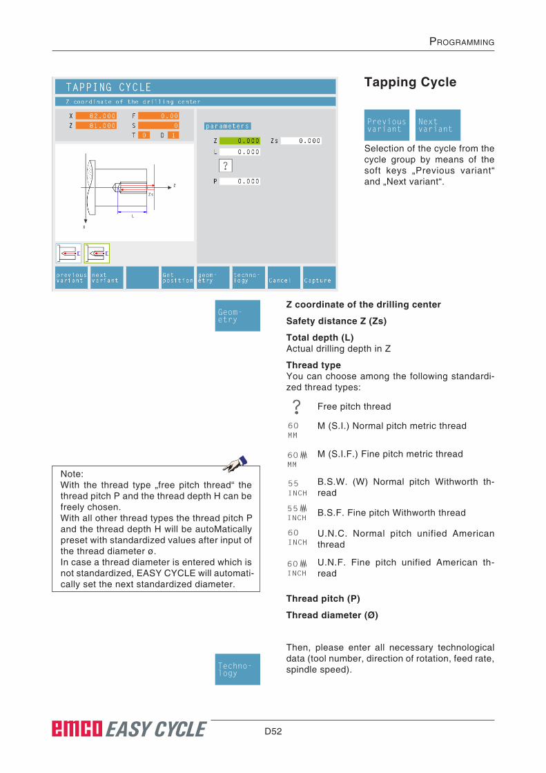
D52 EASY CYCLE
prOgramming
Tapping Cycle
Selection of the cycle from the cycle group by means of the soft keys „Previous variant“ and „Next variant“.
Z coordinate of the drilling center
Safety distance Z (Zs)
Total depth (L)Actual drilling depth in Z
Thread typeYou can choose among the following standardi-zed thread types:
Then, please enter all necessary technological data (tool number, direction of rotation, feed rate, spindle speed).
U.N.F. Fine pitch unified American th-read
U.N.C. Normal pitch unified American thread
B.S.F. Fine pitch Withworth thread
B.S.W. (W) Normal pitch Withworth th-read
M (S.I.F.) Fine pitch metric thread
M (S.I.) Normal pitch metric thread
Free pitch thread
Thread pitch (P)
Thread diameter (ø)
Previousvariant
Nextvariant
Geom-etry
Techno-logy
Note:With the thread type „free pitch thread“ the thread pitch P and the thread depth H can be freely chosen.With all other thread types the thread pitch P and the thread depth H will be autoMatically preset with standardized values after input of the thread diameter ø.In case a thread diameter is entered which is not standardized, EASY CYCLE will automati-cally set the next standardized diameter.
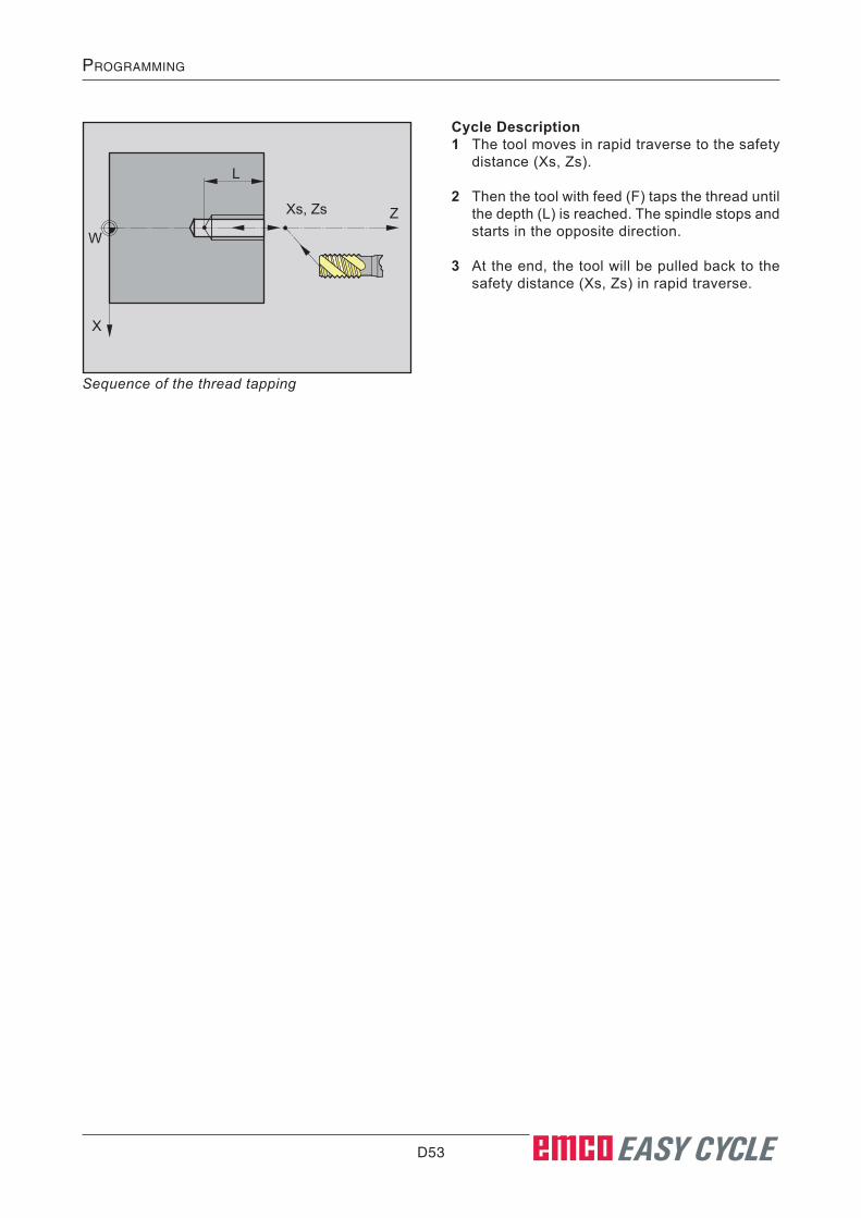
D53 EASY CYCLE
prOgramming
X
W
L
Xs, Zs Z
Cycle Description1 The tool moves in rapid traverse to the safety
distance (Xs, Zs).
2 Then the tool with feed (F) taps the thread until the depth (L) is reached. The spindle stops and starts in the opposite direction.
3 At the end, the tool will be pulled back to the safety distance (Xs, Zs) in rapid traverse.
Sequence of the thread tapping

D54 EASY CYCLE
prOgramming
Positioning
You can traverse or position the tool in a straight way.
Use:
• to position the tool prior to the machining itsself
• to traverse the tool between two cycles
The tool traverses from its current position to its target position in a straight line.
The tool traverses from its current position first in X and then in Z to its target position.
The tool traverses from its current position first in Z and then in X to its target position.
The tool moves at rapid traverse.
The tools moves at the programmed feed rate F.
CoordinatesThe target position is defined by X and Z.
Then, please enter all necessary technological data (tool number, direction of rotation, feed rate, spindle speed).
Geom-etry
Techno-logy

D55 EASY CYCLE
prOgramming
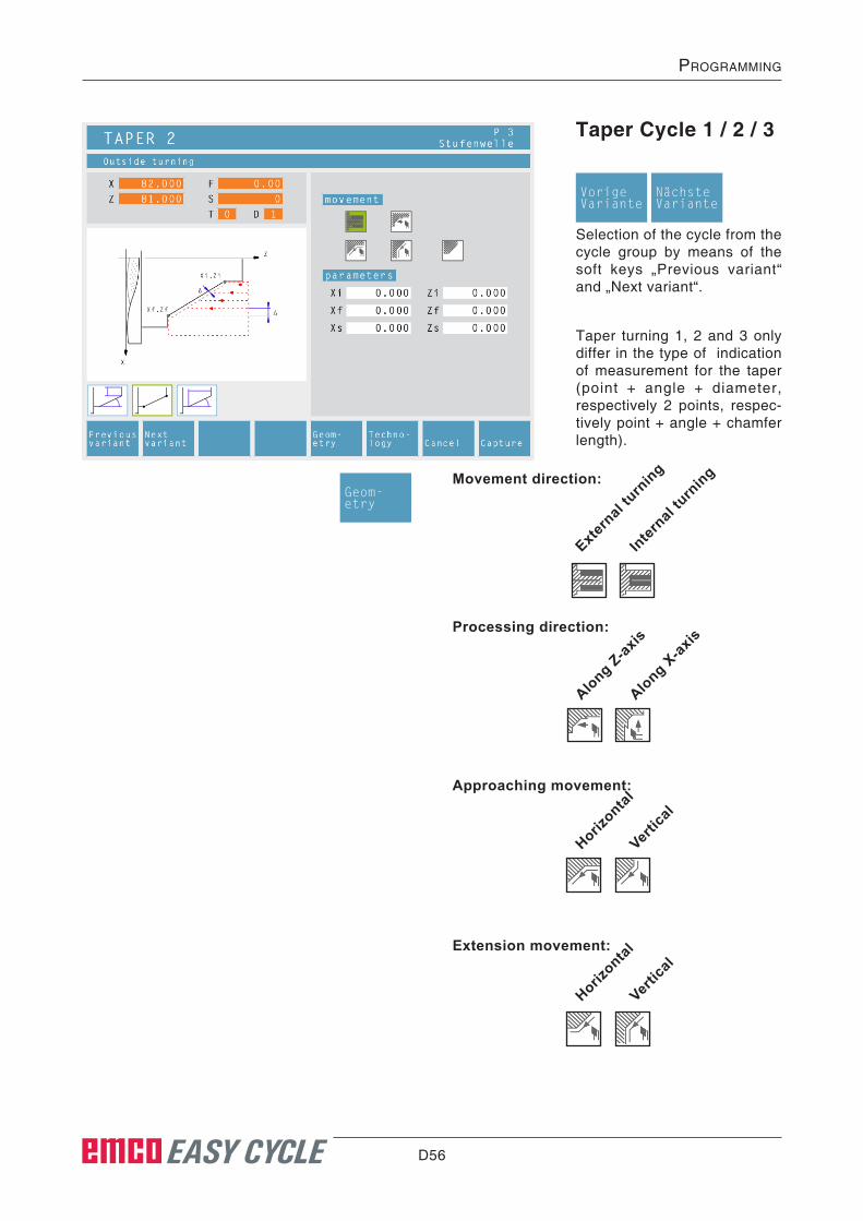
D56 EASY CYCLE
prOgramming
Taper Cycle 1 / 2 / 3
Selection of the cycle from the cycle group by means of the soft keys „Previous variant“ and „Next variant“.
Taper turning 1, 2 and 3 only differ in the type of indication of measurement for the taper (point + angle + diameter, respectively 2 points, respec-tively point + angle + chamfer length).
VorigeVariante
NächsteVariante
Movement direction:Geom-etry
Extern
al tu
rning
Internal
turn
ing
Extension movement:
Horizontal
Vertic
al
Approaching movement:
Horizontal
Vertic
al
Processing direction:
Along Z-axis
Along X-ax
is

D57 EASY CYCLE
prOgramming
Coordinates (Xi, Zi)Coordinates of the starting point.
Diameter (ø)Initial diameter of the taper (only for taper turning 1).
Taper length in Z direction (Z)Lenght of the taper in direction of the Z axis.
Angle (α)Taper angle (only for taper turning 1).
Coordinates (Xf, Zf)Coordinates of the end point (only for taper tur-ning 2).
Safety distance (Xs, Zs)
Approaching and departing the contour with tool radius compensationTo make sure that no corners will be violated and no remaining parts will stay behind during approaching or departing, the form of the corner must be defined.
Picture above: possible quadrantsPicture below: Example: Departing the contour
IncorrectThe tool moves away in straight direction and leaves a remai-ning part.
CorrectThe tool moves around the corner and re-moves the remaining part.
CorrectThe tool moves away in straight direction, the contour remains intact.
IncorrectThe tool moves around the corner and viola-tes the subsequent contour.
vertical horizontal
Taper position:Define the area to be machined in the quadrant.
outside taper front side
inside taper f ront side
outside taper back side
inside taper back side
quadrant Z -
quadrant Z +

D58 EASY CYCLE
prOgramming
Then, please enter all necessary technological data (tool number, direction of rotation, feed rate, spindle speed).
Cutting depth for roughing (∆)Lateral distance by which the tool is shifted during roughing.
Finishing clearance (δ)Clearance that should remain during roughing.
Finishing clearance in the X axis (δx)Clearance that should remain during roughing.
Finishing clearance in the Z axis (δz)Clearance that should remain during roughing.
tool s
hape
axis
Machining direction:
along th
e Z ax
is
along th
e X ax
is
Finishing clearance according to:
Techno-logy

D59 EASY CYCLE
prOgramming
Z
X 1
5
3
Xf, Zf
Xs, Zs
Xi, Zi
42
W
∆δ
Z
X
Xf, Zf
Xs, Zs
Xi, Zi
W
Cycle DescriptionRoughing1 The tool moves in rapid traverse to the safety
distance (Xs, Zs).
2 The tool with roughing feed then rough-ma-chines several grooving operations in suc-cession. In this, each time the tool shifts the roughing infeed by (∆) until the programmed slide allowances (δ or δx, δz) are reached.
Sequence of an individual roughing operation with a processing direction along the Z-axis
Finishing3 If another tool was programmed for the finish-
ing, a tool change will take place at the tool change point.
4 Then the tool with finishing infeed finishes an individual operation.
5 At the end, the tool will be pulled back to the safety distance (Xs, Zs) in rapid traverse.
Sequence of finishing operations with a process-ing direction along the Z-axis

D60 EASY CYCLE
prOgramming
Rounding Cycle
Moving direction:
outsid
e turn
ing
insid
e turn
ing
Approaching movement:
horizonta
l
verti
cal
This cycle serves to creating arc segments.
Contour shape:
conve
x
conca
ve
Machining direction:
along th
e Z ax
is
along th
e X ax
is

D61 EASY CYCLE
prOgramming
Approaching and departing the contour with tool radius compensationTo make sure that no corners will be violated and no remaining parts will stay behind during approaching or departing, the form of the corner must be defined.
Example: Departing the contour
IncorrectThe tool moves away in straight direction and leaves a remai-ning part.
CorrectThe tool moves around the corner and re-moves the remaining part.
CorrectThe tool moves away in straight direction, the contour remains intact.
IncorrectThe tool moves around the corner and viola-tes the subsequent contour.
Departing movement:
horizonta
l
verti
cal
Vertikal Horizontal
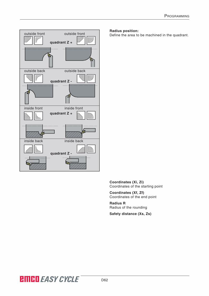
D62 EASY CYCLE
prOgramming
Coordinates (Xi, Zi)Coordinates of the starting point
Coordinates (Xf, Zf)Coordinates of the end point
Radius RRadius of the rounding
Safety distance (Xs, Zs)
Radius position:Define the area to be machined in the quadrant.
inside back inside back
quadrant Z +
inside front inside front
outside back outside back
outside front outside front
quadrant Z +
quadrant Z -
quadrant Z -

D63 EASY CYCLE
prOgramming
Then, please enter all necessary technological data (tool number, direction of rotation, feed rate, spindle speed).
Techno-logy
Cutting depth for roughing (∆)Lateral distance by which the tool is shifted during roughing.
tool s
hape
axis
Finishing clearance according to:
Finishing clearance (δ)Clearance that should remain during roughing.
Finishing clearance in the X axis (δx)Clearance that should remain during roughing.
Finishing clearance in the Z axis (δz)Clearance that should remain during roughing.

D64 EASY CYCLE
prOgramming
Z
X 1
5
3
Xf, Zf
Xs, Zs
Xi, Zi
42
W
∆δ
Z
X
Xf, Zf
Xs, Zs
Xi, Zi
W
Cycle DescriptionRoughing1 The tool moves in rapid traverse to the safety
distance (Xs, Zs).
2 The tool with roughing feed then rough-ma-chines several operations in succession. In this, each time the tool shifts the roughing infeed by (∆) until the programmed slide al-lowances (δ or δx, δz) are reached.
Sequence of an individual roughing operation with a processing direction along the Z-axis
Finishing3 If another tool was programmed for the finish-
ing, a tool change will take place at the tool change point.
4 Then the tool with finishing infeed finishes an individual operation.
5 At the end, the tool will be pulled back to the safety distance (Xs, Zs) in rapid traverse.
Sequence of finishing operations with a process-ing direction along the Z-axis

D65 EASY CYCLE
prOgramming
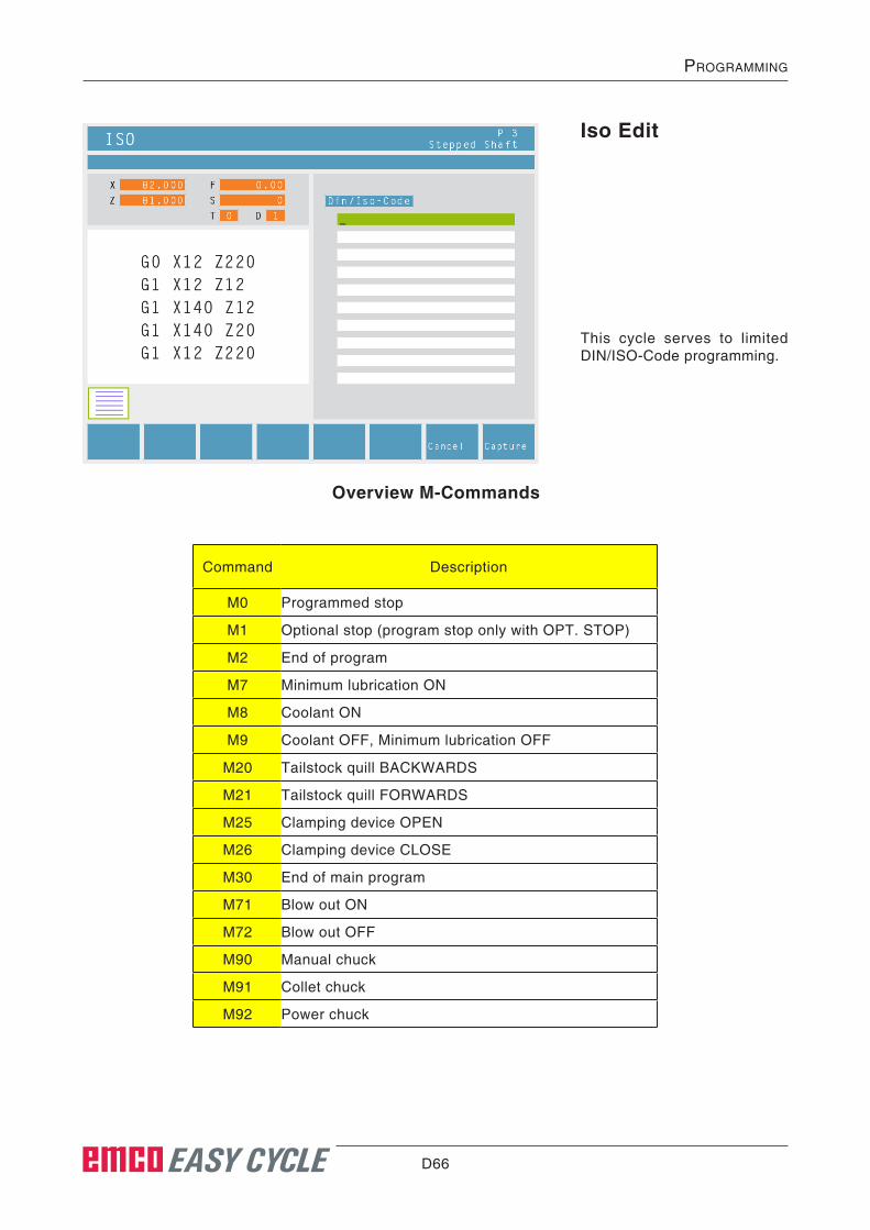
D66 EASY CYCLE
prOgramming
Overview M-Commands
Iso Edit
This cycle serves to limited DIN/ISO-Code programming.
Command Description
M0 Programmed stop
M1 Optional stop (program stop only with OPT. STOP)
M2 End of program
M7 Minimum lubrication ON
M8 Coolant ON
M9 Coolant OFF, Minimum lubrication OFF
M20 Tailstock quill BACKWARDS
M21 Tailstock quill FORWARDS
M25 Clamping device OPEN
M26 Clamping device CLOSE
M30 End of main program
M71 Blow out ON
M72 Blow out OFF
M90 Manual chuck
M91 Collet chuck
M92 Power chuck
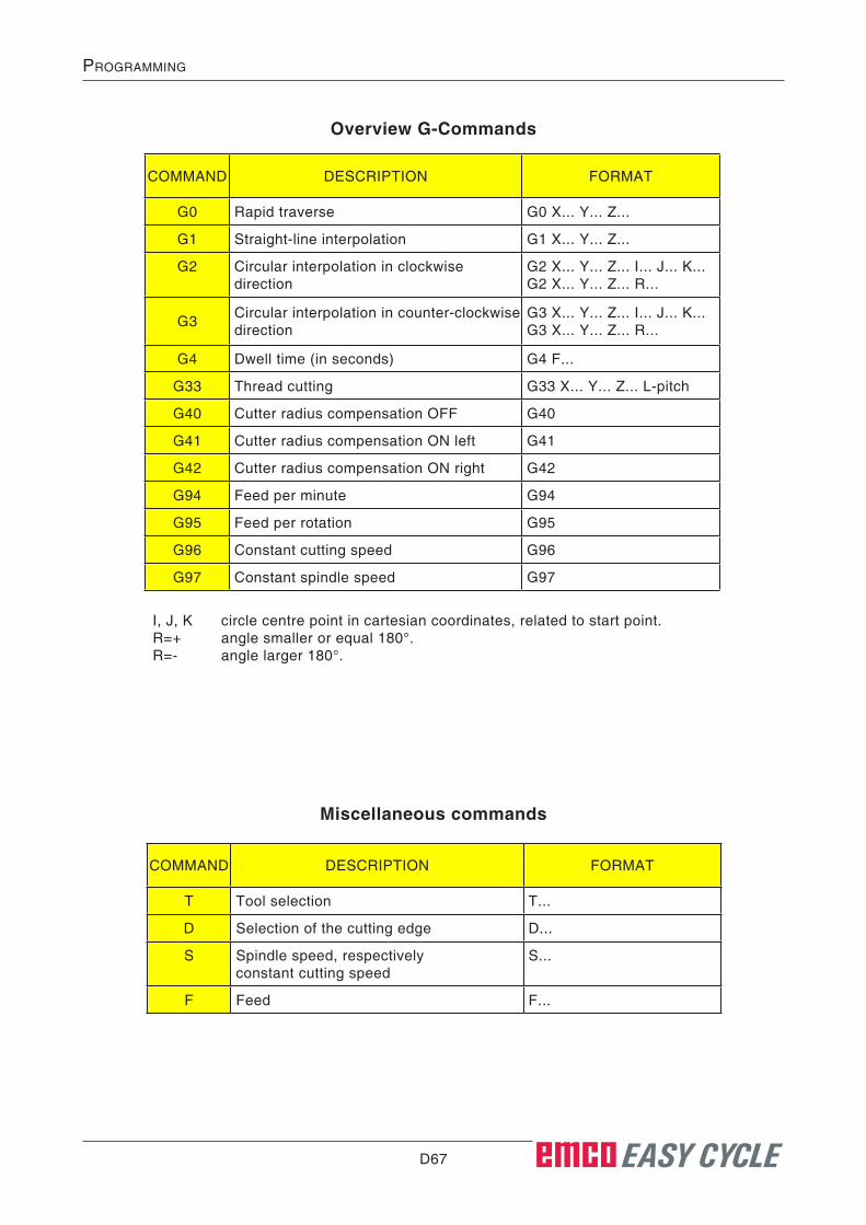
D67 EASY CYCLE
prOgramming
COMMAND DESCRIPTION FORMAT
G0 Rapid traverse G0 X... Y... Z...
G1 Straight-line interpolation G1 X... Y... Z...
G2 Circular interpolation in clockwise direction
G2 X... Y... Z... I... J... K... G2 X... Y... Z... R...
G3 Circular interpolation in counter-clockwise direction
G3 X... Y... Z... I... J... K... G3 X... Y... Z... R...
G4 Dwell time (in seconds) G4 F...
G33 Thread cutting G33 X... Y... Z... L-pitch
G40 Cutter radius compensation OFF G40
G41 Cutter radius compensation ON left G41
G42 Cutter radius compensation ON right G42
G94 Feed per minute G94
G95 Feed per rotation G95
G96 Constant cutting speed G96
G97 Constant spindle speed G97
COMMAND DESCRIPTION FORMAT
T Tool selection T...
D Selection of the cutting edge D...
S Spindle speed, respectively constant cutting speed
S...
F Feed F...
Overview G-Commands
Miscellaneous commands
I, J, K circle centre point in cartesian coordinates, related to start point.R=+ angle smaller or equal 180°.R=- angle larger 180°.

D68 EASY CYCLE
prOgramming
Coordinate transformation
The cycle „Coordinate transformation“ serves to zero offset the workpiece zero point (W). The following possibilities exist:
Absolute Zero-Off-set
Coordinates (X, Z)Absolute zero-offset of the workpiece zero point (W):
X...absolute zero-offset on the X axisZ...absolute zero-offset on the Z axis
Incremental Zero-Offset
Coordinates (∆x, ∆z)Incremental zero-offset of the workpiece zero point (W):
∆x...incremental zero-offset on the X axis∆z...incremental zer-offset on the Z axis
Coord.Trans.

D69 EASY CYCLE
prOgramming
Cancel Zero-Offset
The zero offset of the work-piece zero point (W) is can-celled.
Call subprogramIn the cycle „Call subprogram“, you can select a program from the program list that will be used as subprogram in the future.
CallSubprog.
Number of repetitions (N)
ProgrammesSelect a program from the program list.
selected program

D70 EASY CYCLE
prOgramming

E1 EASY CYCLE
tOOl measurement
E: Tool measurement
• Deleting an existing tool.• Renaming an existing tool.• Copying an existing tool to
the last position of the tool table.
• Measuring a tool at the ma-chine.
• Entering a tool or a new cut-ting edge in the tool table.
Defining tool data• Fasten a workpiece of known height in the
toolholder.• Press the soft key.• Define the following parameters: • Xm...X-coordinate of the reference part • Zm...Z-coordinate of the reference part • X...tool length in X • Z...tool length in Z • I...wear in X • K...wear in Z
Tooltable
Geometry
The tool measurement enables you to edit the tool system of the NC machine:

E2 EASY CYCLE
tOOl measurement
Editing tool data• You create blades for the tools here.
• You delete tool data for the tool here.
• You delete tools here.
• You change the name for the tool here.
• You load tools for 3D View here.
Insertedge
Resettool
Deletetool
Changename
Tooldatabase
Instructions:The tool database is only active if EMCO Win 3D-View is installed in the same directory as WinNC EASY CYCLE.
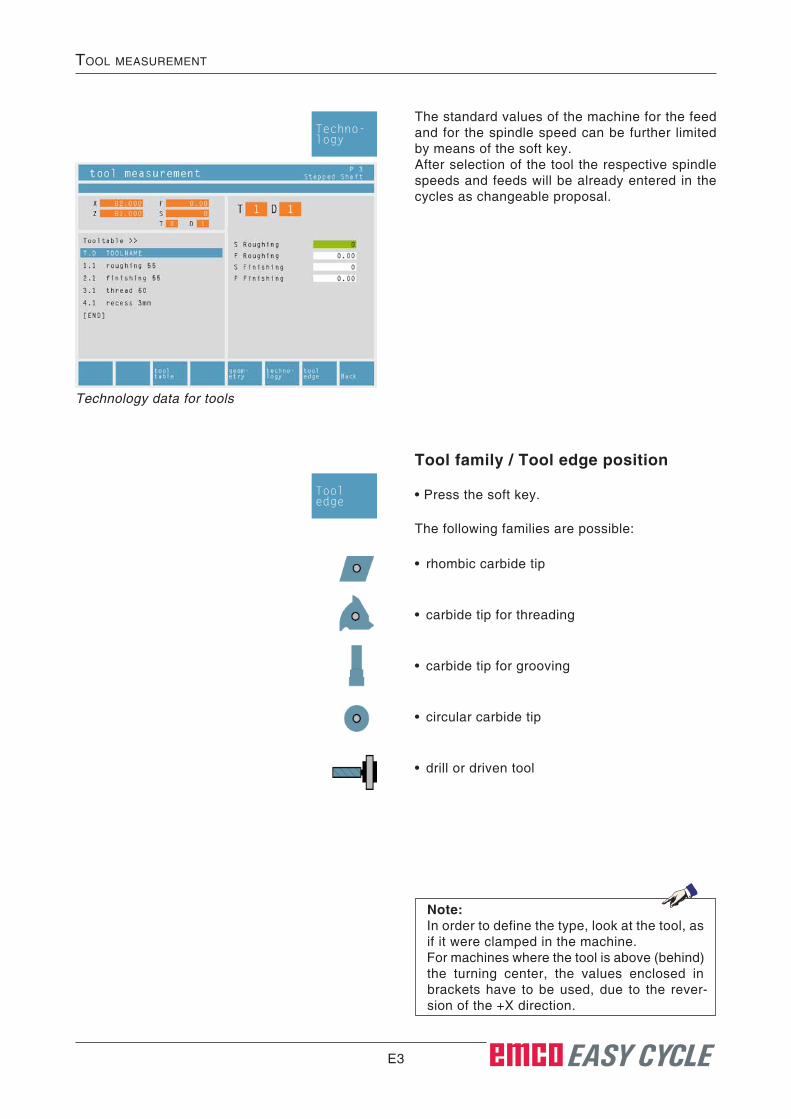
E3 EASY CYCLE
tOOl measurement
Tool family / Tool edge position
The following families are possible:
• rhombic carbide tip
• carbide tip for threading
• carbide tip for grooving
• circular carbide tip
• drill or driven tool
• Press the soft key.
Note:In order to define the type, look at the tool, as if it were clamped in the machine.For machines where the tool is above (behind) the turning center, the values enclosed in brackets have to be used, due to the rever-sion of the +X direction.
Technology data for tools
The standard values of the machine for the feed and for the spindle speed can be further limited by means of the soft key.After selection of the tool the respective spindle speeds and feeds will be already entered in the cycles as changeable proposal.
Techno-logy
Tooledge
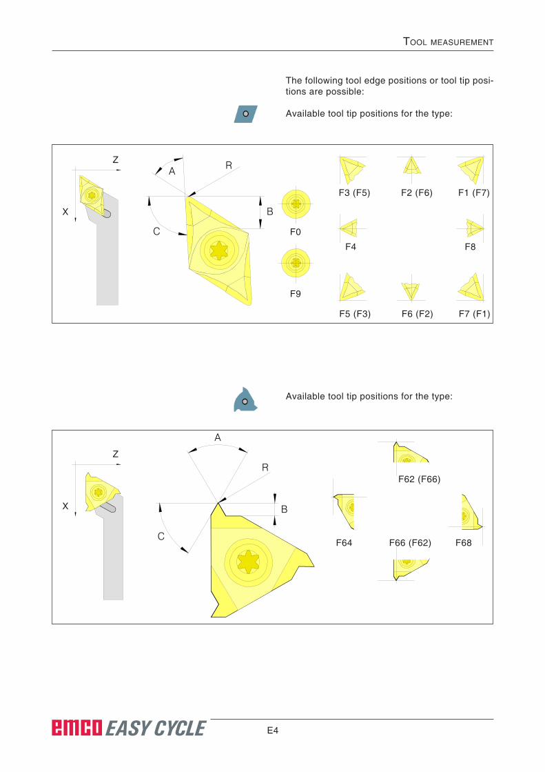
E4 EASY CYCLE
tOOl measurement
Available tool tip positions for the type:
The following tool edge positions or tool tip posi-tions are possible:
Available tool tip positions for the type:
F3 (F5) F2 (F6) F1 (F7)
F4 F8
F5 (F3) F6 (F2) F7 (F1)
F0
F9
X
ZA
C
B
R
F64 F66 (F62) F68
F62 (F66)
A
C
B
R
X
Z

E5 EASY CYCLE
tOOl measurement
Available tool tip positions for the type:
Available tool tip positions for the type:
F25 F26 F27
F23 F22 F21
F35
F34
F37
F38
F33 F31
A=90C=90
X
Z
F43 (F45) F42 (F46) F41 (F47)
F45 (F43) F46 (F42) F47 (F41)
F55 (F53) F47 (F51)
F53 (F55) F51 (F57)
F54 F50 F59 F58F49
F40
A=90B=2RC=0
X
Z
R
B
R
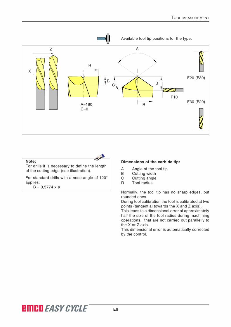
E6 EASY CYCLE
tOOl measurement
Available tool tip positions for the type:
Note:For drills it is necessary to define the length of the cutting edge (see illustration).
For standard drills with a nose angle of 120° applies: B = 0,5774 x ø
Dimensions of the carbide tip:
A Angle of the tool tipB Cutting widthC Cutting angleR Tool radius
Normally, the tool tip has no sharp edges, but rounded ones.During tool calibration the tool is calibrated at two points (tangential towards the X and Z axis).This leads to a dimensional error of approximately half the size of the tool radius during machining operations, that are not carried out parallelly to the X or Z axis.This dimensional error is automatically corrected by the control.
F20 (F30)
F30 (F20)F10
R
BC
A
B
RA=180C=0
X
Z

E7 EASY CYCLE
tOOl measurement
Tool calibration with optical presetting device1.) Gauging the optical tool preset-ting device:
• Install the optical tool presetting device.
• Clamp the reference tool together with the tool-holder into the tool turret disc.
• Create the reference tool as drill or cutter.
• Enter the correction values X=0 and Z=20 (CT105), respectively Z=30 (CT55).
• Swivel the reference tool in and traverse the tool tip into the cross hairs.
• Define Z=0 and confirm with the enter key. The question "Setting reference point?" will appear. Please confirm with the enter key.
• Call the tool table and select the reference tool position.
• Enter Xm= (enter the displayed position value of the X axis) and Zm=0.
Now, the presettings for the tool calibration are completed.
Position value displayed in X
Xm
Reference tool Concept Turn 55 / 105
Calibration of the reference tool
CT55
CT105
Z
N
30 mm
Z
N
20 mm
CT55
CT105
Geometry
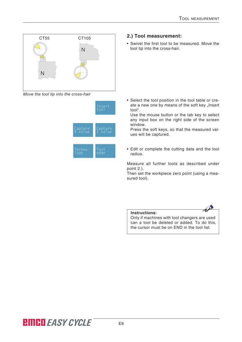
E8 EASY CYCLE
tOOl measurement
2.) Tool measurement:• Swivel the first tool to be measured. Move the
tool tip into the cross-hair.
Move the tool tip into the cross-hair• Select the tool position in the tool table or cre-
ate a new one by means of the soft key „Insert tool“.
Use the mouse button or the tab key to select any input box on the right side of the screen window.
Press the soft keys, so that the measured val-ues will be captured.
• Edit or complete the cutting data and the tool radius.
Measure all further tools as described under point 2.).Then set the workpiece zero point (using a mea-sured tool).
N
N
CT55 CT105
Tooledge
Inserttool
Capture Z value
CaptureX value
Techno-logy
Instructions:Only if machines with tool changers are used can a tool be deleted or added. To do this, the cursor must be on END in the tool list.

E9 EASY CYCLE
tOOl measurement
Tool measurement with touch-ing method• Press the soft key.
• Enter the tool name.
• Enter the Xm value of the reference part.
• Define the Zm value (length between the ma-chine zero point and the plane surface) of the reference part with „0“.
Note:The data X and Z define the dimensions of the tool in X and Z. The data I and K define the correction value that EASY CYCLE has to consider in order to compensate for the tool wear.EASY CYCLE adds the value of the correc-tion value (I,K) to the length (X, Z) in order to get the actual tool length (X+I) and (Z+K), it has to use.The value "I" (correction value of the longitu-dinal wear in X direction) must be defined in diameters.
• Touch the tool at the circumference of the work-piece and press the soft key.
• Touch the tool at the face of the workpiece and press the soft key.
• Now, the tool is measured. EASY CYCLE re-freshes the data X and Z and sets the values for I and K to 0.
• If necessary, define the cutting data for the respective tool types.
Inserttool
CaptureZ value
CaptureX value
Changename

E10
F1 EASY CYCLE
prOgram run
F: Program run
RequirementsDatum settingThe used datums must be measured and ente-red.
ToolsThe used tools must be measured and entered.The tools must be located at the corresponding position (T) in the tool changer.
Reference pointThe reference point must be traversed in all axes.
MachineThe machine must be ready for operation.The workpiece must be clamped safely.Loose parts (clamping keys, etc.) must not be in the working place in order to avoid collisions.The machine door must be close before the pro-gram is started.
AlarmsThere must not be any alarms activated.
Note:It is not allowed to change tool settings of used tools during program run.
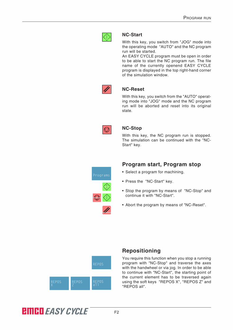
F2 EASY CYCLE
prOgram run
NC-StartWith this key, you switch from "JOG" mode into the operating mode "AUTO" and the NC program run will be started.An EASY CYCLE program must be open in order to be able to start the NC program run. The file name of the currently openend EASY CYCLE program is displayed in the top right-hand corner of the simulation window.
NC-ResetWith this key, you switch from the "AUTO" operat-ing mode into "JOG" mode and the NC program run will be aborted and reset into its original state.
NC-StopWith this key, the NC program run is stopped. The simulation can be continued with the "NC-Start" key.
Program start, Program stop• Select a program for machining.
• Press the "NC-Start" key.
• Stop the program by means of "NC-Stop" and continue it with "NC-Start".
• Abort the program by means of "NC-Reset".
Repositioning You require this function when you stop a running program with "NC-Stop" and traverse the axes with the handwheel or via jog. In order to be able to continue with "NC-Start", the starting point of the current element has to be traversed again using the soft keys "REPOS X", "REPOS Z" and "REPOS all".
Programs
REPOS
REPOSX
REPOSZ
REPOSall

H1
alarms and messages
H: Alarms and MessagesMachine Alarms 6000 - 7999These alarms will be triggered by the machines.There are different alarms for the different ma-chines.The alarms 6000 - 6999 normally must be con-firmed with RESET. The alarms 7000 - 7999 are messages which normally will disappear when the releasing situation is finished.
PC MILL 50 / 55 / 100 / 105 / 125 / 155Concept MILL 55 / 105 / 155
6000: EMERGENCY OFFThe EMERGENCY OFF key was pressed. Remo-ve the endangering situation and restart machine and software.
6001: PLC-CYCLE TIME EXCEEDINGContact EMCO Service.
6002: PLC - NO PROGRAM CHARGEDContact EMCO Service.
6003: PLC - NO DATA UNITContact EMCO Service.
6004: PLC - RAM MEMORY FAILUREContact EMCO Service.
6005: OVERHEAT BRAKEMODULMain drive was braked too often, large changes of speed within a short time. E4.2 active
6006: OVERLOAD BRAKE RESISTORsee 6005
6007: SAFETY CIRCUIT FAULTAxis and main drive contactor with machine swit-ched off not disabled. Contactor got stuck or con-tact error. E4.7 was not active during switch-on.
6009: SAFETY CIRCUIT FAULTDefective step motor system.A running CNC program will be interrupted, the auxiliary drives will be stopped, the reference position will be lost.Contact EMCO Service.
6010: DRIVE X-AXIS NOT READYThe step motor board is defective or too hot, a fuse or cabling is defective.A running program will be stopped, the auxiliary drives will be switched off, the reference position will be lost.Check fuses or contact EMCO service.
6011: DRIVE Y-AXIS NOT READYsee alarm 6010.
6012: DRIVE Z-AXIS NOT READYsee alarm 6010.
6013: MAIN DRIVE NOT READYMain drive power supply defective, main drive too hot, fuse defective.A running program will be stopped, the auxilliary drives will be switched off.Check fuses or contact EMCO Service.
6014: NO MAIN SPINDLE SPEEDThis will be released, when the spindle speed is lower than 20 rpm because of overload.Alter cutting data (feed, infeed, spindle speed).The CNC program will be aborted, the auxilliary drives will be stopped.
6019: VICE TIME EXCEEDThe electric vice has not reached a stop position within 30 seconds.The control or the clamping device board are defective, the vice is stuck. Adjust the proximity switches of the stop position.
C 2008-12
H2
alarms and messages
6020: VICE FAILUREWhen the electric vice is closed, the signal "clam-ping device clamped" of the clamping device board has failed.The control, the clamping device board or the wiring are defective.
6022: CLAMPING DEVICE BOARD DEFECTI-VE
The signal "clamping device clamped" is con-stantly released, although no command has been given.Replace the board.
6024: MACHINE DOOR OPENThe door was opened while a machine movement. The program will be aborted.
6027: DOOR LIMIT SWITCH DEFECTIVEThe limit switch of the automatic door is displaced, defective, wrong cabled.Contact EMCO service.
6028: DOOR TIMEOUTThe automatic door stucks, the pressured air sup-ply is insufficient, the limit switch is displaced.Check door, pressured air supply, limit switch or contact EMCO service.
6030: NO PART CLAMPEDNo workpiece inserted, vice cheek displaced, control cam displaced, hardware defective.Adjust or contact EMCO service.
6040: TOOL TURRET INDEX FAILUREAfter WZW procedure drum pressed down by Z-axis. Spindle position wrong or mechanical defect. E4.3=0 in lower state
6041: TOOL CHANGE TIMEOUTTool drum stucks (collision?), main drive not rea-dy, fuse defective, hardware defective.A running CNC program will be stopped.Check for collisions, check fuses or contact EMCO service.
6043-6046: TOOL DISK POSITION FAULTPosition error of main drive, error of position super vising (inductive proximity switch defective or disadjusted, drum allowance), fuse defective, hardware defective.The Z axis could have been slipped out of the toothing while the machine was switched off.A running CNC program will be stopped.Contact EMCO service.
6047: TOOL DISK UNLOCKEDTool drum turned out of locked position, inductive proximity switch defective or disadjusted, fuse defective, hardware defective.A running CNC program will be interrupted.Contact EMCO service.When the tool drum is turned out of locked posi-tion (no defect), act as following:Turn the drum into locking position manuallyChange into MANUAL (JOG) mode.Turn the key switch. Traverse the Z slide upwards, until the alarm disappears.
6048: DIVIDING TIME EXCEEDEDDividing head stucks, insufficient pressured air supply, hardware defective.Check for collision, check pressured air supply or contact EMCO service.
6049: INTERLOCKING TIME EXCEEDEDsee alarm 6048
6050: M25 AT RUNNING MAIN SPINDLECause: Programming mistake in NC program.A running program will be aborted.The auxilliary drives will be switched off.Remedy: Correct NC program
6064: DOOR AUTOMATIC NOT READYCause: pressure failure automatic door automatic door stucks mechanically limit switch for open end position defecti-
ve security print circuits defect cabling defective fuses defectiveA running program will be aborted.The auxilliary drives will be switched off.Remedy: service automatic door
6069: CLAMPING FOR TANI NOT OPENWhen opening the clamping pressure switch does not fall within 400ms. Pressure switch defective or mechanical problem. E22.3
6070: PRESSURE SWITCH FOR TANI MIS-SING
When closing the clamping pressure switch does not respond. No compressed air or mechanical problem. E22.3
6071: DIVIDING DEVICE NOT READYServo Ready Signal from frequency converter missing. Excess temperature drive TANI or fre-quency converter not ready for operation.

H3
alarms and messages
6072: VICE NOT READYAttempt to start the spindle with an open vice or without clamped workpiece.Vice stucks mechanically, insufficient compressed air supply, compressed air switch defective, fuse defective, hardware defective.Check the fuses or contact EMCO service.
6073: DIVIDING DEVICE NOT READYCause: locking switch defective cabling defective fuses defectiveA running program will be aborted.The auxilliary drives will be switched off.Remedy: service automatic dividing device lock the dividing device
6074: DIVIDING TIME EXCEEDEDCause: dividing device stucks mechanically locking switch defective cabling defective fuses defective insufficient compressed-air supply.A running program will be aborted.The auxilliary drives will be switched off.Remedy: Check for collision, check the compressed-
air supply or contact the EMCO service.
6075: M27 AT RUNNING MAIN SPINDLECause: Programming mistake in NC program.A running program will be aborted.The auxilliary drives will be switched off.Remedy: Correct NC program
7000: INVALID TOOL NUMBER PROGRAM-MED
The tool position was programmed larger than 10.The CNC program will be stopped.Interrupt program with RESET and correct the program.
7001: NO M6 PROGRAMMEDFor an automatic tool change you also have to program a M6 after the T word.
7007: FEED STOP!The axes have been stopped by the robotics in-terface (robotics entry FEEDHOLD).
7016: SWITCH ON AUXILIARY DRIVESThe auxiliary drives are off. Press the AUX ON key for at least 0.5 sec. (to avoid accidentally switching on) to switch on the auxiliary drives.
7017: REFERENCE MACHINEApproach the reference point.When the reference point is not active, manual movements are possible only with key switch at position "setting operation".
7018: TURN KEY SWITCHWith NC-Start the key switch was in position "set-ting operation".NC-Start is locked.Turn the key switch in the position "automatic" to run a program.
7020: SPECIAL OPERATION MODE ACTIVESpecial operation mode: The machine door is opened, the auxiliary drives are switched on, the key switch is in position "setting operation" and the consent key is pressed.Manual traversing the axes is possible with open door. Swivelling the tool turret is not possible with open door. Running a CNC program is possible only with standing spindle (DRYRUN) and SIN-GLE block operation.For safety: If the consent key is pressed for more than 40 sec. the function of this key is interrupted, the consent key must be released and pressed again.
7021: INITIALIZE TOOL TURRETThe tool turret operating was interrupted.No traversing operation is possible.Press tool turret key in JOG operation. Message occurs after alarm 6040.
7022: INITIALIZE TOOL TURRET !see 7021
7023: WAITING TIME MAIN DRIVE!The LENZE frequency converter has to be se-parated from the mains supply for at least 20 seconds before you are allowed to switch it on again. This message will appear when the door is quickly openend/ closed (under 20 seconds).
7038: LUBRICATION SYSTEM FAULTThe pressure switch is defective or gagged.NC-Start is locked. This can be reset only by switching off and on the machine.Contact EMCO service.
7039: LUBRICATION SYSTEM FAULTNot enough lubricant, the pressure switch is de-fective.NC-Start is locked.Check the lubricant and lubricate manually or contact EMCO service.

H4
alarms and messages
7040: MACHINE DOOR OPENThe main drive can not be switched on and NC-Start can not be activated (except special opera-tion mode)Close the machine to run a program.
7042: INITIALIZE MACHINE DOOREvery movement and NC-Start are locked.Open and close the machine door to initialize the safety circuits.
7043: PIECE COUNT REACHEDA predetermined number of program runs was reached. NC-Start is locked. Reset the counter to continue.
7050: NO PART CLAMPEDAfter switching on or after an the vice is neither at the open position nor at the closed position.NC-Start is locked.Traverse the vice manually on a valid end posi-tion.
7051: DIVIDING HEAD NOT LOCKED!Either the dividing head is in an undefined po-sition after the machine has been switched on, or the locking signal after a dividing process is missing.Initiate the dividing process, check, respectively adjust the proximity switch for locking.
7054: VICE OPENCause: the workpiece is not clampedWhen switching on the main spindle with M3/M4 alarm 6072 (vice not ready) will be released.Remedy: Clamp
7055: OPEN TOOL CLAMPING SYSTEMA tool is clamped in the main spindle and the control does not recognize the corresponding T number.Eject the tool from the main spindle when the door is open by means of the PC keys "Strg" and " 1 ".
7056: SETTING DATA INCORRECTAn invalid tool number is stored in the setting data.Delete the setting data in the machine directory xxxxx.pls.
7057: TOOLHOLDER OCCUPIEDThe clamped tool cannot be positioned in the tool turret since the position is occupied.Eject the tool from the main spindle when the door is open by means of the PC keys "Strg" and " 1 ".
7058: RETRACTING THE AXESThe position of the tool turret arm cannot be clear-ly defined during the tool change.Open the machine door, push the tool turret ma-gazine backwards to the stop. Move the milling head in the JOG mode upwards to the Z reference switch and then traverse the reference point.
7270: OFFSET COMPENSATION ACTIVE !Only with PC-MILL 105Offset compensation activated by the following operation sequence.- Reference point not active- Machine in reference mode- Key switch in manual operation- Press STRG (or CTRL) and simultaneously 4This must be carried out if prior to the tool change procedure spindle positioning is not completed (tolerance window too large)
7271: COMPENSATION FINISHED,DATA SAVED !
see 7270

H5
alarms and messages

H6
alarms and messages
6000: EMERGENCY OFFThe EMERGENCY OFF key was pressed.The reference position will be lost, the auxiliary drives will be switched off.Remove the endangering situation and restart machine and software.
6001: PLC-CYCLE TIME EXCEEDINGThe auxiliary drives will be switched off.Contact EMCO Service.
6002: PLC - NO PROGRAM CHARGEDThe auxiliary drives will be switched off.Contact EMCO Service.
6003: PLC - NO DATA UNITThe auxiliary drives will be switched off.Contact EMCO Service.
6004: PLC - RAM MEMORY FAILUREThe auxiliary drives will be switched off.Contact EMCO Service.
6005: K2 OR K3 NOT DE-ENERGIZEDTurn machine on/off. Defective security board.
6006 EMERGENCY-OFF RELAY K1 NOT DE-ENERGIZED
Turn machine on/off. Defective security board.
6007 SAFETY CIRCUIT FAULT
6008: MISSING CAN SUBSCRIBERThe PLC-CAN board is not identified by the con-trol.Check the interface cable and the power supply of the CAN board.
6009: SAFETY CIRCUIT FAULT
6010: DRIVE X-AXIS NOT READYThe step motor board is defective or too hot, a fuse is defective, over- or undervoltage from mains.A running program will be stopped, the auxiliary drives will be switched off, the reference position will be lost.Check fuses or contact EMCO service.
6011: DRIVE Z-AXIS NOT READYsee 6010.
6012: DRIVE Z-AXIS NOT READYsee 6010.
6013: MAIN DRIVE NOT READYMain drive power supply defective or main drive too hot, fuse defective, over- or undervoltage from mains.A running program will be stopped, the auxilliary drives will be switched off.Check fuses or contact EMCO Service.
6014: NO MAIN SPINDLE SPEEDThis alarm will be released, when the spindle speed is lower than 20 rpm because of over-load.Alter cutting data (feed, infeed, spindle speed).The CNC program will be aborted, the auxiliary drives will be switched off.
6015: NO DRIVEN TOOL SPINDLE SPEEDsee 6014.
6016: AUTOMATIC TOOL TURRET SIGNAL COUPLED MISSING
6017: AUTOMATIC TOOL TURRET SIGNAL UNCOUPLED MISSING
In the tool turret that can be coupled, the position of the coupling and uncoupling magnet is moni-tored by means of two proximity switches. It has to be made sure that the coupling is in the rear stop position so that the tool turret can get to the next tool position. Equally, during operation with driven tools the coupling has to be safe in the front stop position.Check and adjust the cables, the magnet and the stop position proximity switches.
6018: AS SIGNALS, K4 OR K5 NOT DE-EN-ERGIZED
Turn machine on/off. Defective security board.
PC TURN 50 / 55 / 105 / 120 / 125 / 155Concept TURN 55 / 105 / 155 / 250Concept MILL 250EMCOMAT E160EMCOMILL C40

H7
alarms and messages
6019: POWER SUPPLY MODULE NOT READY
Turn machine on/off. Power supply module, de-fective axis controller 6020 AWZ drive failure turn machine on/off, defective axis controller.
6021: COLLET TIME OUTDuring closing of the clamping device the pressu-re switch has not reacted within one second.
6022: CLAMPING DEVICE BOARD DEFECTI-VE
The signal "clamping device clamped" is constant-ly released, even though no command has been given. Replace the board.
6023: COLLET PRESSURE MONITORINGThe pressure switch turns off when the clamping device is closed (compressed air failure for more than 500ms).
6024: MACHINE DOOR OPENThe door was opened while a machine movement. The program will be aborted.
6025: GEARBOX COVER NOT CLOSEDThe gearbox cover was opened while a machi-ne movement. A running CNC program will be aborted.Close the cover to continue.
6026: MOTOR PROTECTION COOLANT PUMP RELEASED
6027: DOOR LIMIT SWITCH DEFECTIVEThe limit switch of the automatic door is displaced, defective, wrong cabled.Contact EMCO service.
6028: DOOR TIMEOUTThe automatic door stucks, the pressured air sup-ply is insufficient, the limit switch is displaced.Check door, pressured air supply, limit switch or contact EMCO service.
6029: TAILSTOCK qUILL TIME EXCEEDThe tailstock quill does not reach a final position within 10 seconds.Adjust the control and the stop position proximity switches, or the tailstock quill is stuck.
6030: NO PART CLAMPEDNo workpiece inserted, vice cheek displaced, control cam displaced, hardware defective.Adjust or contact EMCO service.
6031: qUILL FAILURE
6032: TOOL CHANGE TIMEOUTsee alarm 6041.
6033: TOOL TURRET SYNC ERRORHardware defective.Contact EMCO service.
6037: CHUCK TIMEOUTThe pressure switch does not react within one second when the clamping device is closed.
6039: CHUCK PRESSURE FAILUREThe pressure switch turns off when the clamping device is closed (compressed air failure for more than 500ms).
6040: TOOL TURRET INDEX FAILUREThe tool turret is in no locked position, tool turret sensor board defective, cabling defective, fuse defective.A running CNC program will be stopped.Swivel the tool turret with the tool turret key, check fuses or contact EMCO service.
6041: TOOL CHANGE TIMEOUTTool drum stucks (collision?), fuse defective, hardware defective.A running CNC program will be stopped.Check for collisions, check fuses or contact EMCO service.
6042: TOOL TURRET OVERHEATTool turret motor too hot.With the tool turret a max. of 14 swivel procedures a minute may be carried out.
6043: TOOL CHANGE TIMEOUTTool drum stucks (collision?), fuse defective, hardware defective.A running CNC program will be stopped.Check for collisions, check fuses or contact EMCO service.
6045: TOOL TURRET SYNC MISSINGHardware defective.Contact EMCO service.
6046: TOOL TURRET ENCODER FAULTFuse defective, hardware defective.Check fuses or contact EMCO service.
H8
alarms and messages
6048: CHUCK NOT READYAttempt to start the spindle with open chuck or without clamped workpiece.Chuck stucks mechanically, insufficient pressured air supply, fuse defective, hardware defective.Check fuses or contact EMCO service.
6049: COLLET NOT READYsee 6048
6050: M25 DURING SPINDLE ROTATIONWith M25 the main spindle must stand still (consider run-out time, evtl. program a dwell)
6055: NO PART CLAMPEDThis alarm occurs when with rotating spindle the clam-ping device or the tailstock reach the end position.The workpiece has been pushed out of the chuck or has been pushed into the chuck by the tailstock.Check clamping device settings, clamping forces, alter cutting data.
6056: qUILL NOT READYAttempt to start the spindle or to move an axis or to swivel the tool turret with undefined tailstock position.Tailstock is locked mechanically (collision), in-sufficient pressured air supply, fuse defective, magnetic switch defective.Check for collisions, check fuses or contact EMCO service.
6057: M20/M21 DURING SPINDLE ROTATI-ON
With M20/M21 the main spindle must stand still (con-sider run-out time, evtl. program a dwell)
6058: M25/M26 DURING qUILL FORWARDTo actuate the clamping device in an NC program with M25 or M26 the tailstock must be in back end position.
6059: C-AXIS SWING IN TIMEOUTC-axis does not swivel in within 4 seconds.Reason: not sufficient air pressure, and/or me-chanics stuck.
6060: C-AXIS INDEX FAILUREWhen swivelling in the C-axis the limit switch does not respond.Check pneumatics, mechanics and limit switch.
6064: AUTOMATIC DOOR NOT READYDoor stucks mechanically (collision), insufficient pressured air supply, limit switch defective, fuse defective.Check for collisions, check fuses or contact EMCO service.
6065: LOADER MAGAZINE FAILURELoader not ready.Check if the loader is switched on, correctly con-nected and ready for operation and/or disable loader (WinConfig).
6066: CLAMPING DEVICE FAILURENo compressed air at the clamping deviceCheck pneumatics and position of the clamping device proximity detectors.
6067: NO COMPRESSED AIRTurn the compressed air on, check the setting of the pressure switch.
6068: MAINDRIVE OVERTEMPERATURE
6070: LIMIT SWITCH TAILSTOCK SLEEVE ACTIVE
6071: LIMIT SWITCH X AXIS ACTIVE
6072: LIMIT SWITCH Z AXIS ACTIVE
6073: CHUCK GUARD OPEN
6074: NO FEEDBACK FROM USB-PLCTurn machine on/off. Check cabling, defective USB board.
6075: AXIS LIMIT SWITCH TRIGGERED
6900 USBPLC not availableCause: USB communication with the safety board
could not be established.Remedy: Switch the machine off and on again. Please
contact the EMCO after-sales service in case the error occurs repeatedly.
6901 Error emergency-off relay USBPLCCause: USBPLC EMERGENCY-OFF relay er-
ror.Remedy: Switch the machine off and on again. Please
contact the EMCO after-sales service in case the error occurs repeatedly.

H9
alarms and messages
6902 Error standstill monitoring XCause: Unauthorized movement of the X axis in
the current operating condition.Remedy: Delete the alarm with the RESET button
and switch the machine off and on again. Please contact the EMCO after-sales ser-vice in case the error occurs repeatedly.
6903 Error standstill monitoring ZCause: Unauthorized movement of the Z axis in
the current operating condition.Remedy: Delete the alarm with the RESET button
and switch the machine off and on again. Please contact the EMCO after-sales ser-vice in case the error occurs repeatedly.
6904 Error alive circuit PLCCause: Error in the connection (Watchdog) of the
safety board with the PLC.Remedy: Delete the alarm with the RESET button and
switch the machine off and on again. Please contact the EMCO after-sales service in case the error occurs repeatedly.
6905 Error overspeed spindleCause: The main spindle speed exceeds the
maximum permissible value for the current operating condition.
Remedy: Delete the alarm with the RESET button and switch the machine off and on again. Please contact the EMCO after-sales service in case the error occurs repeatedly.
6906 Error enable pulses I/F-moduleCause: ACC-PLC did not shutdown the input/nega-
tive feeder-module.Remedy: Delete the alarm with the RESET button
and switch the machine off and on again. Please contact the EMCO after-sales ser-vice in case the error occurs repeatedly.
6907 Error standstill monitoring main driveCause: Unexpeced warm up of the main spindle
in the operating condition.Remedy: Delete the alarm with the RESET button
and switch the machine off and on again. Please contact the EMCO after-sales ser-vice in case the error occurs repeatedly.
6908 Error main drive enable without spin-dle startCause: The release of the control unit of the main
spindle was given by the ACC-PLC without the spindle-start key being pressed.
Remedy: Delete the alarm with the RESET button and switch the machine off and on again. Please contact the EMCO after-sales ser-vice in case the error occurs repeatedly.
6909 Error standstill monitoring YCause: Unauthorized movement of the Y axis in
the current operating condition.Remedy: Delete the alarm with the RESET button
and switch the machine off and on again. Please contact the EMCO after-sales ser-vice in case the error occurs repeatedly.
6910 Error standstill axesCause: Unauthorized movement of the axis in the
current operating condition.Remedy: Delete the alarm with the RESET button
and switch the machine off and on again. Please contact the EMCO after-sales ser-vice in case the error occurs repeatedly.
6911 Error overspeed axisCause: The feed of the axes exceeds the maximum permissible value for the current ope-rating condition.Remedy: Delete the alarm with the RESET button
and switch the machine off and on again. Please contact the EMCO after-sales ser-vice in case the error occurs repeatedly.
6912 Error overspeed XCause: The feed of the X axis exceeds the maxi-
mum permissible value for the current operating condition.
Remedy: Delete the alarm with the RESET button and switch the machine off and on again. Please contact the EMCO after-sales ser-vice in case the error occurs repeatedly.
6913 Error overspeed YCause: The feed of the Y axis exceeds the maxi-
mum permissible value for the current operating condition.
Remedy: Delete the alarm with the RESET button and switch the machine off and on again. Please contact the EMCO after-sales ser-vice in case the error occurs repeatedly.

H10
alarms and messages
6914 Error overspeed ZCause: The feed of the Y axis exceeds the maxi-
mum permissible value for the current operating condition.
Remedy: Delete the alarm with the RESET button and switch the machine off and on again. Please contact the EMCO after-sales ser-vice in case the error occurs repeatedly.
7000: INVALID TOOL NUMBER PROGRAM-MED
The tool position was programmed larger than 8.The CNC program will be stopped.Interrupt program with RESET and correct the program.
7007: FEED HOLDIn the robotic mode a HIGH signal is at input E3.7. Feed Stop is active until a low signal is at E3.7.
7016: SWITCH ON AUXILIARY DRIVESThe auxiliary drives are off. Press the AUX ON key for at least 0.5 sec. (to avoid accidentally swit-ching on) to switch on the auxiliary drives (also a lubricating pulse will be released).
7017: REFERENCE MACHINEApproach the reference point.When the reference point is not active, manual movements are possible only with key switch at position "setting operation".
7018: TURN KEY SWITCHWith NC-Start the key switch was in position "set-ting operation".NC-Start is locked.Turn the key switch in the position "automatic" to run a program.
7019: PNEUMATIC LUBRICATION MONI-TORING!
Refill pneumatic oil
7020: SPECIAL OPERATION MODE ACTIVESpecial operation mode: The machine door is opened, the auxiliary drives are switched on, the key switch is in position "setting operation" and the consent key is pressed.Manual traversing the axes is possible with open door. Swivelling the tool turret is possible with open door. Running a CNC program is possible only with standing spindle (DRYRUN) and SIN-GLE block operation.For safety: If the consent key is pressed for more than 40 sec. the function of this key is interrupted, the consent key must be released and pressed again.
7021: TOOL TURRET NOT LOCKEDThe tool turret operating was interrupted.NC start and spindle start are locked. Press the tool turret key in the RESET status of the con-trol.
7022: COLLECTION DEVICE MONITORINGTime exceed of the swivelling movement.Check the pneumatics, respectively whether the mechanical system is jammed (possibly a work-piece is jammed).
7023: ADJUST PRESSURE SWITCH !During opening and closing of the clamping de-vice the pressure switch has to turn off and on once.Adjust the pressure switch. This alarm does not exist any more for versions starting with PLC 3.10.
7024: ADJUST CLAMPING DEVICE PRO-XIMITY SWITCH !
When the clamping device is open and the positi-on stop control is active, the respective proximity switch has to feed back that the clamping device is "Open".Check and adjust the clamping device proximity switch, check the cables.
7025 WAITING TIME MAIN DRIVE !The LENZE frequency converter has to be se-parated from the mains supply for at least 20 seconds before you are allowed to switch it on again. This message will appear when the door is quickly openend/ closed (under 20 seconds).
7026 PROTECTION MAIN MOTOR FAN RE-LEASED!
H11
alarms and messages
7038: LUBRICATION SYSTEM FAULTThe pressure switch is defective or gagged.NC-Start is locked. This alarm can be reset only by switching off and on the machine.Contact EMCO service.
7039: LUBRICATION SYSTEM FAULTNot enough lubricant, the pressure switch is de-fective.NC-Start is locked.Check the lubricant and lubricate manually or contact EMCO service.
7040: MACHINE DOOR OPENThe main drive can not be switched on and NC-Start can not be activated (except special opera-tion mode)Close the machine to run a program.
7041: GEARBOX COVER OPENThe main spindle cannot be switched on and NC start cannot be activated.Close the gearbox cover in order to start a CNC program.
7042: INITIALIZE MACHINE DOOREvery movement and NC-Start are locked.Open and close the machine door to initialize the safety circuits.
7043: PIECE COUNT REACHEDA predetermined number of program runs was reached. NC-Start is locked. Reset the counter to continue.
7048: CHUCK OPENThis message shows that the chuck is open. It will disappear if a workpiece will be clamped.
7049: CHUCK - NO PART CLAMPEDNo part is clamped, the spindle can not be swit-ched on.
7050: COLLET OPENThis message shows that the collet is open. It will disappear if a workpiece will be clamped.
7051: COLLET - NO PART CLAMPEDNo part is clamped, the spindle can not be swit-ched on.
7052: qUILL IN UNDEFINED POSITIONThe tailstock is in no defined position.All axis movements, the spindle and the tool turret are locked.Drive the tailstock in back end position or clamp a workpiece with the tailstock.
7053: qUILL - NO PART CLAMPEDThe tailstock reached the front end position. Tra-verse the tailstock back to the back end position to continue.
7054: NO PART CLAMPEDNo part clamped, switch-on of the spindle is locked.
7055: CLAMPING DEVICE OPENThis message indicates that the clamping device is not in clamping state. It disappears as soon as a part is clamped.
7060 RETRACT SLEEVE LIMIT SWITCH !7061 RETRACT X AXIS LIMIT SWITCH !7062 RETRACT Z AXIS LIMIT SWITCH !7063 OIL LEVEL CENTRAL LUBRICATION !7064 CHUCK GUARD OPEN !7065 MOTOR PROTECTION COOLANT
PUMP RELEASED !7066 CONFIRM TOOL !7067 MANUAL OPERATING MODE7068 X AXIS HANDWHEEL ACTIVE7069 Y AXIS HANDWHEEL ACTIVE7070 Z AXIS HANDWHEEL ACTIVE7071 VERTICAL TOOL CHANGE7072 HORIZONTAL TOOL CHANGE7073 RETRACT Y AXIS LIMIT SWITCH !7074 CHANGE TOOL

H12
alarms and messages

H13
alarms and messages
8000 Fatal Error AC8100 Fatal init error ACCause: Internal errorRemedy: Restart software or reinstall when neces-
sary, report to EMCO, if repeatable.8101 Fatal init error ACsee 8101.8102 Fatal init error ACsee 8101.8103 Fatal init error ACsee 8101.8104 Fatal system error ACsee 8101.8105 Fatal init error ACsee 8101.8106 No PC-COM card foundCause: PC-COM board can not be accessed (ev.
not mounted).Remedy: Mount board, adjust other address with
jumper8107 PC-COM card not workingsee 8106.8108 Fatal error on PC-COM cardsee 8106.8109 Fatal error on PC-COM cardsee 8106.8110 PC-COM init message missingCause: Internal errorRemedy: Restart software or reinstall when neces-
sary, report to EMCO, if repeatable.8111 Wrong configuration of PC-COMsee 8110.8113 Invalid data (pccom.hex)see 8110.8114 Programming error on PC-COMsee 8110.8115 PC-COM packet acknowledge missingsee 8110.8116 PC-COM startup errorsee 8110.8117 Fatal init data error (pccom.hex)see 8110.8118 Fatal init error ACsee 8110, ev. insufficient RAM memory
8119 PC interrupt no. not validCause: The PC interrupt number can not be
used.Remedy: Find out free interrupt number in the Win-
dows95 system control (allowed: 5,7,10, 11, 12, 3, 4 und 5) and enter this number in WinConfig.
8120 PC interrupt no. unmaskablesee 81198121 Invalid command to PC-COMCause: Internal error or defective cableRemedy: Check cables (screw it); Restart software or
reinstall when necessary, report to EMCO, if repeatable.
8122 Internal AC mailbox overrunCause: Internal errorRemedy: Restart software or reinstall when neces-
sary, report to EMCO, if repeatable.8123 Open error on record fileCause: Internal errorRemedy: Restart software or reinstall when neces-
sary, report to EMCO, if repeatable.8124 Write error on record fileCause: Internal errorRemedy: Restart software or reinstall when neces-
sary, report to EMCO, if repeatable.8125 Invalid memory for record bufferCause: Insufficient RAM, record time exceeding.Remedy: Restart software, ev. remove drivers etc.
to gain more RAM, reduce record time.8126 AC Interpolation overrunCause: Ev. insufficient computer performance.Remedy: Set a longer interrupt time in WinConfig.
This may result in poorer path accuracy.8127 Insufficient memoryCause: Insufficient RAMRemedy: Close other programs, restart software, ev.
remove drivers etc. to gain more RAM.8128 Invalid message to ACCause: Internal errorRemedy: Restart software or reinstall when neces-
sary, report to EMCO, if repeatable.8129 Invalid MSD data - axisconfig.see 8128.8130 Internal init error ACsee 8128.8130 Internal init error ACsee 8128.
Axis Controller Alarms
H14
alarms and messages
8132 Axis accessed by multiple channelssee 8128.8133 Insufficient NC block memory ACsee 8128.8134 Too much center points programmedsee 8128.8135 No centerpoint programmedsee 8128.8136 Circle radius too smallsee 8128.8137 Invalid for Helix specifiedCause: Wrong axis for helix. The combination of
linear and circular axes does not match.Remedy: Program correction.8140 Maschine (ACIF) not respondingCause: Machine off or not connected.Remedy: Switch on machine or connect.8141 Internal PC-COM errorCause: Internal errorRemedy: Restart software or reinstall when neces-
sary, report to EMCO, if repeatable.8142 ACIF Program errorCause: Internal errorRemedy: Restart software or reinstall when neces-
sary, report to EMCO, if repeatable.8143 ACIF packet acknowledge missingsee 8142.8144 ACIF startup errorsee 8142.8145 Fatal init data error (acif.hex)see 8142.8146 Multiple request for axissee 8142.8147 Invalid PC-COM state (DPRAM)see 8142.8148 Invalid PC-COM command (CNo)see 8142.8149 Invalid PC-COM command (Len)see 8142.8150 Fatal ACIF errorsee 8142.8151 AC Init Error (missing RPG file)see 8142.8152 AC Init Error (RPG file format)see 8142.8153 FPGA program timeout on ACIFsee 8142.8154 Invalid Command to PC-COMsee 8142.
8155 Invalid FPGA packet acknowledgesee 8142 or hardware error on ACIF board (contact EMCO Service).8156 Sync within 1.5 revol. not foundsee 8142 or Bero hardware error (contact EMCO Service).8157 Data record donesee 8142.8158 Bero width too large (referencing)see 8142 or Bero hardware error (contact EMCO Service).8159 Function not implementedBedeutung: In normal operation this function can
not be executed8160 Axis synchronization lost axis 3..7Cause: Axis spins or slide is locked, axis synchro-
nisation was lostRemedy: Approach reference point8161 X-Axis synchronization lostStep loss of the step motor. Causes:- Axis mechanically blocked- Axis belt defective- Distance of proximity detector too large (>0,3mm) or proximity detector defective- Step motor defective8162 Y-Axis synchronization lostsee 81618163 Z-Axis synchronization lostsee 81618164 Software limit switch max axis 3..7Cause: Axis is at traverse area endRemedy: Retract axis8168 Software limit overtravel axis 3..7Cause: Axis is at traverse area endRemedy: Retract axis8172 Communication error to machineCause: Internal errorRemedy: Restart software or reinstall when neces-
sary, report to EMCO, if repeatable. Check connection PC - machine, eventually
eliminate distortion sources.8173 INC while NC program is runningRemedy: Stop the program with NC stop or with
Reset. Traverse the axis.8174 INC not allowedCause: At the moment the axis is in motion.Remedy: Wait until the axis stops and then traverse
the axis.8175 MSD file could not be openedCause: Internal errorRemedy: Restart software oder bei Bedarf neu in-
stallieren, report to EMCO, if repeatable.

H15
alarms and messages
8176 PLS file could not be openedsee 8175.8177 PLS file could not be accessedsee 8175.8178 PLS file could not be writtensee 8175.8179 ACS file could not be openedsee 8175.8180 ACS file could not be accessedsee 8175.8181 ACS file could not be writtensee 8175.8183 Gear too highCause: The selected gear step is not allowed at
the machine. 8184 Invalid interpolaton command8185 Forbidden MSD data changesee 8175.8186 MSD file could not be openedsee 8175.8187 PLC program errorsee 8175.8188 Gear command invalidsee 8175.8189 Invalid channel assignementsee 8175.8190 Invalid channel within messagesee 8175.8191 Invalid jog feed unitCause: The machine does not support the rotation
feed in the JOG operating mode.Remedy: Order a software update from EMCO.8192 Invalid axis in commandsee 8175.8193 Fatal PLC errorsee 8175.8194 Thread without lengthCause: The programmed target coordinates are
identical to the starting coordinates.Remedy: Correct the target coordinates.8195 No thread slope in leading axisRemedy: Program thread pitch8196 Too manny axis for threadRemedy: Program max. 2 axes for thread.8197 Thread not long enoughCause: Thread length too short. With transition from one thread to the other
the length of the second thread must be sufficient to produce a correct thread.
Remedy: Longer second thread or replace it by a linear interpolation (G1).
8198 Internal error (to manny threads)see 8175.8199 Internal error (thread state)Cause: Internal errorRemedy: Restart software or reinstall when neces-
sary, report to EMCO, if repeatable.8200 Thread without spindle onRemedy: Switch on spindle8201 Internal thread error (IPO)see 8199.8201 Internal thread error (IPO)see 8199.8203 Fatal AC error (0-ptr IPO)see 8199.8204 Fatal init error: PLC/IPO runningsee 8199.8205 PLC Runtime exceededCause: Insufficient computer performance8206 Invalid PLC M-group initialisationsee 8199.8207 Invalid PLC machine datasee 8199.8208 Invalid application messagesee 8199.8212 Rotation axis not allowedsee 8199.8213 Circle and rotation axis can't be inter-polated8214 Thread and rotation axis cant't be inter-polated8215 Invalid statesee 8199.8216 No rotation axis for rotation axis switchsee 8199.8217 Axis type not valid!Cause: Switching during the rotary axis operating
mode when the spindle is running.Remedy: Stop the spindle and switch over to the
rotary axis operating mode.8218 Referencing round axis without selec-ted round axis!see 8199.8219 Thread not allowed without spindle encoder!Cause: Thread cutting, respectively tapping is only
possible with spindles with encoders.8220 Buffer length exceeded in PC send message!see 8199.8221 Spindle release although axis is no spindle!see 8199.

H16
alarms and messages
8222 New master spindle is not validCause: The indicated master spindle is not valid
when switching over to the master spind-le.
Remedy: Correct the spindle number.8224 Invalid stop modesee 8199.8225 Invalid parameter for BC_MOVE_TO_IO!Cause: The machine is not configurated for touch
probes. A traversing movement with rotary axis is not allowed during touch probe operating mode.
Remedy: Remove the rotary axis movement from the traversing movement.
8226 Rotary axis switch not valid (MSD data)!Cause: The indicated spindle does not have a
rotary axis.8228 Rotary axis switch not allowed while axis move!Cause: The rotary axis has moved during switching
over to the spindle operating mode.Remedy: Stop the rotary axis before switching.8229 Spindle on not allowed while rotary axis is active!8230 Program start not allowed due to active spindle rotation axis!8231 Axis configuration (MSD) for TRANSMIT not valid!Cause: Transmit is not possible at this machine.8232 Axis configuration (MSD) for TRACYL not valid!Cause: Tracyl is not possible at this machine.8233 Axis not available while TRANSMIT/TRACYL is active!Cause: Programming of the rotary axis is not allo-
wed during Transmit/ Tracyl.8234 Axis control grant removed by PLC while axis interpolates!Cause: Internal errorRemedy: Delete error with reset and inform
EMCO.8235 Interpolation invalid while axis control grant is off by PLC!see 8234.8236 TRANSMIT/TRACYL activated while axis or spindle moves!see 8234.8237 Motion through pole in TRANSMIT!Cause: It is not allowed to move through the co-
ordinates X0 Y0 inTransmit.Remedy: Alter the traversing movement.
8238 Speed limit in TRANSMIT exceeded!Cause: The traversing movement gets too close to
the coordinates X0 Y0. In order to observe the programmed feed rate, the maximum speed of the rotary axis would have to be exceeded.
Remedy: Reduce the feed rate. Set the value of the C-axis feed limitation in WinConfig, machine data settings / general machine data/ to 0.2. Thus, the feed rate will be automatically reduced near the coordinates X0 Y0.
8239 DAU exceeded 10V limit!Cause: Internal errorRemedy: Start the software again or install it anew.
Report the error to EMCO.8240 Function not valid during active trans-formation (TRANSMIT/TRACYL)!Cause: The Jog and INC operating mode are not
possible during Transmit in X/C and during Tracyl in the rotary axis.
8241 TRANSMIT not enabled (MSD)!Cause: Transmit is not possible at this machine.8242 TRACYL not enabled (MSD)!Cause: Tracyl is not possible at this machine.8243 Round axis invalid during active trans-formation!Cause: It is not allowed to program the rotary axis
during Transmit/Tracyl.8245 TRACYL radius = 0!Cause: When selecting Tracyl, a radius of 0 was
used.Remedy: Correct the radius.8246 Offset alignment not valid for this state!see 8239.8247 Offset alignment: MSD file write protec-ted!8248 Cyclic supervision failed!Cause: The communication with the machine
keyboard is interrupted.Remedy: Start the software again or install it anew.
Report the error to EMCO.8249 Axis motion check alarm!see 82398250 Spindle must be rotation axis !see 82398251 Lead for G331/G332 missing !Cause: The threading pitch is missing or the star-
ting coordinates are identical to the target coordinates.
Remedy: Program the threading pitch. Correct the target coordinates.

H17
alarms and messages
8252 Multiple or no linear axis programmed for G331/G332 !Remedy: Program exactly one linear axis.8253 Speed value for G331/G332 and G96 missing !Cause: No cutting speed has been programmed.Remedy: Program the cutting speed.8254 Value for thread starting point offset not valid!Cause: The thread starting point offset is not within
the range of 0 to 360°.Remedy: Correct the thread starting point offset.8255 Reference point not in valid software limits!Cause: The reference point has been defined
outside the software limit switches.Remedy: Correct the reference points in WinCon-
fig.8256 Spindle speed too low while executing G331/G332!Cause: During tapping the spindle speed has de-
creased. Perhaps the incorrect threading pitch was used or the core drilling is not correct.
Remedy: Correct the threading pitch. Adapt the diameter to the core drilling.
8257 Real Time Module not active or PCI card not found!Cause: ACC could not be started correctly or the
PCI card in the ACC was not recogni-zed.
Remedy: Report the error to EMCO.8258 Error allocating Linux data!see 8239.8259 Current thread in sequence not valid!Cause: One block of a thread in sequence has
been programmed without thread G33.Remedy: Correct the program.8261 Missing thread in sequence !Cause: A successive thread has not been pro-
grammed for a thread in sequence, the number has to be in accordance with the SETTHREADCOUNT () that has been defined before.
Remedy: Correct the number of threads in the thread in sequence and add a thread.
8262 Reference marks are not close enough !Cause: The settings of the linear scale have been
changed or the linear scale is defective.Remedy: Correct the settings. Contact EMCO.8263 Reference marks are too close tog-ether!see 8262.
8265 No or wrong axis in axis switch com-mand!Cause: Internal error.Remedy: Please contact the EMCO after-sales
service.22000 Gear change not allowedCause: Gear step change when the spindle is
active.Remedy: Stop the spindle and carry out a gear step
change.22270 Feed too high (thread)Cause: Thread pitch too large / missing, Feed for
thread reaches 80% of rapid feedRemedy: Program correction, lower pitch or lower
spindle speed for thread

H18
alarms and messages
Axis Controller Messages
8700 Execute REPOS in all axes before pro-gram startCause: After the program was stopped, the axes
were manipulated with the hand wheel or with the jog keys and then a restart of the program was attempted.
Remedy: Before starting the program again, one should reposition the axes along the con-tour by executing "REPOS".
8701 No NCStop during offset alignCause: The machine is currently executing an
automatic offset adjustment. NC stop is not possible at this time.
Remedy: Wait until the offset adjustment is finished and then stop the program with NC stop.
8702 No NCStop during positioning after block searchCause: The machine is currently finishing the block
search operation and then it starts to go back to the last programmed position. No NC stop is possible in the meantime.
Remedy: Wait until positioning is finished and then stop the program with NC stop.
8703 Data record doneThe recording of data is finished and the file record.acp has been copied to the installation folder.

H19
alarms and messages
Control alarms 2000 - 5999The alarms are released by the software.
Fagor 8055 TC/MC Heidenhain TNC 426 CAMConcept EASY CYCLE
2000 departure missingCause: No movement after the tool radius com-
pensation was deactivated in the current plane.
Remedy: Insert the departing movement in the cur-rent plane after having deactivated the tool radius compensation.
2001 TPC off missingCause: The tool radius compensation has not been
deactivated.Remedy: Deactivate the tool radius compensation.
2002 less than three moves for TPCCause: The tool radius compensation requires at
least 3 movements in the current plane in order to calculate the tool radius compen-sation (movement for approach, compen-sated movement, departing movement.
2200 Syntax error in line %s, column %sCause: Syntax error in the program code.
2300 tracyl without corresponding round-axis invalidCause: Maybe the machine has no rotary axis.
3000 Traverse feed axis manually to position %sRemedy: Move the axis manually to the required
position.
4001 slot width too smallCause: The tool radius is too large for the slot to
be milled.
4002 slot length to smallCause: The slot length is too small for the slot to
be milled.
4003 length equal zeroCause: Pocket length, pocket width, stud length,
stud width are zero.
4004 slot width too bigCause: The programmed slot width is larger than
the slot length.
4005 depth equal zeroCause: No machining takes place since no effec-
tive cutting depth has been defined.
4006 corner radius too bigCause: The corner radius is too large for the size
of the pocket.
4007 diameter too bigCause: The remaining material (nominal diameter
- diameter of the prebore) /2 is larger than the tool diameter.
4008 diameter too smallCause: The tool diamter is too large for the intended
bore.Remedy: Enlarge the nominal diameter and use a
smaller milling cutter.
4009 length too smallCause: Width and length must be larger than the
double tool radius.
H20
alarms and messages
4010 diameter less equal zeroCause: The pocket diameter, the stud diameter,
etc. must not be zero.
4011 blank diameter too bigCause: The diameter of the machined pocket
must be larger than the diameter of the premachined pocket.
4012 blank diameter too smallCause: The diameter of the machined stud must
be smaller than the diameter of the premachined stud.
4013 start angle equal to end angleCause: Start angle and end angle for hole pattern
are identical.
4014 tool radius 0 not permittedCause: Tool radius zero is not permitted.Remedy: Select a valid tool.
4015 no outer contour definedCause: The contour file indicated in the cycle was
not found.
4017 tool radius too bigCause: For the programmed machining, a tool
being too large was selected. Therefore, machining is not possible.
4018 allowance must not be 0Cause: There were programmed finishing opera-
tions without finishing offset.
4019 too many iterationsCause: The contour definitions are too complex
for the roughing-out cycle.Remedy: Simplify the contour.
4020 illegal radian correctionCause: An error has occured during the program-
ming of the radius compensation.Remedy: Check the cycle parameters.
4021 can't calculate parallel contourCause: The control was not able to calculate the
tool radius compensation.Remedy: Check the programmed contour for plau-
sibility. Maybe contact EMCO.
4022 illegal contour definitionCause: The programmed contour is not suited to
the selected machining.Remedy: Check the programmed contour.
4024 no contour definitionCause: The contour file being defined in the cyle
has not been found.
4025 internal calculation errorCause: An unexpected error has occured during
calculation of the cycle movements.Remedy: Please inform the EMCO after-sales ser-
vice.
4026 allowance too bigCause: A part of the finishing offset (for several
finishing passes) is larger than the total finishing offset.
Remedy: Correc the finishing offsets.
4028 pitch 0 not permittedCause: The thread was programmed with pitch
zero.
4029 undefinded working modeCause: Internal error (invalid machining type for
the thread).
4030 function not yet supportedCause: Roughing out with pockets is not imple-
mented yet.Remedy: Please inform the EMCO after-sales ser-
vice.
4031 value not permittedCause: An invalid retracting direction was pro-
grammed during inside turning.
4032 plunging must be definedCause: For the programmed cycle no cutting depth
has been programmed.
4033 radius/chamfer too bigCause: The radius, respectively the chamfer,
cannot be inserted in the programmed contour.
Remedy: Reduce the radius, respectively the cham-fer.
4034 diameter too bigCause: The programmed starting point and the
machining diameter are contradictory.
H21
alarms and messages
4035 diameter too smallCause: The programmed starting point and the
machining diameter are contradictory.
4036 unknown working directionCause: Internal error.Remedy: Please inform the EMCO after-sales ser-
vice.
4037 unknown working typeCause: Internal error.Remedy: Please inform the EMCO after-sales ser-
vice.
4038 unknown sub cycleCause: Internal error.Remedy: Please inform the EMCO after-sales ser-
vice.
4039 rounding not possibleCause: The programmed radius contradicts the
rest of the cycle parameters.
4042 illegal tool widthCause: The tool width for the cutting-off cycle must
be defined.
4043 groove width too smallCause: Internal error.Remedy: Please inform the EMCO after-sales ser-
vice.
4044 distance not definedCause: The distance for the multiple grooving cycle
must not be zero.
4045 illegal allowance typeCause: Internal error.Remedy: Please inform the EMCO after-sales ser-
vice.
4046 invalid speedCause: The spindle speed must be nonzero.
4047 invalid end pointCause: The programmed end point contradicts the
rest of the cycle definition.
4048 tool cut width too smallCause: The cutting edge is too small for the pro-
grammed cutting depth.
4050 invalid distanceCause: The hole patterns do not tally with the
selected distance.
4052 working pattern not possibleCause: Error in the definition of the hole pattern.
The number of bores is contradictory.
4053 invalid start pointCause: Internal error.Remedy: Please inform the EMCO after-sales ser-
vice.
4055 illegal working directionCause: The machining direction is contradictory
to the rest of the cycle definition.
4057 plunging angle less equal zeroCause: The plunging angle must be between 0
and 90 degree.
4058 chamfer too largeCause: The programmed chamfer is too large for
the pocket cycle.
4062 radius/chamfer too smallCause: The radius, respectively the chamfer,
cannot be machined with the current tool radius.
4066 invalid mill stepCause: The mill step must be greater than zero.
4069 invalid angleCause: An angle of zero degree is not permitted.
4072 plunging too smallCause: For the cycle, a cutting depth has been
selected that leads to extra-long machining time.
4073 invalid clearance angleCause: The clearance angle indicated for the tool
cannot be machined.Remedy: Correct the clearance angle for the tool.
4074 contour-file not foundCause: The contour file indicated in the cycle has
not been found.Remedy: Please select the contour file for the
cycle.

H22
alarms and messages
4075 not machinable with selected toolCause: The tool is too wide for the programmed
groove.
4200 leaving movement is missingCause: No movement after the tool radius com-
pensation was deactivated in the current plane.
Remedy: Insert the departing movement in the cur-rent plane after having deactivated the tool radius compensation.
4201 G40 is missingCause: The tool radius compensation has not been
deactivated. Remedy: Deactivate the tool radius compensation.
4202 TPC requires at least three movementsCause: The tool radius compensation requires at
least 3 movements in the current plane in order to calculate the tool radius compen-sation.
4203 approaching movement not possibleCause: It was not possible to calculate the ap-
proaching movement.
4205 leaving movement not possibleCause: It was not possible to calculate the depart-
ing movement.
4209 TPC curve could not be calculatedCause: It was not possible to calculate the tool
radius compensation for the programmed contour.
4210 switching the plane is not allowed when TPC is switched onCause: The programmed plane must not be
changed during the tool radius compensa-tion.
Remedy: Remove the change of planes during the tool radius compensation.
5000 drill manually now
5001 contour has been adjusted to the pro-grammed clearance angleCause: The programmed contour was adapted to
the programmed clearance angle. Maybe there will remain rest material that cannot be machined with this tool.

X1
emCOnFig
X: EmConfig
General
EmConfig is a configuration software for WinNC.EmConfig helps you to alter the settings of WinNC.
The most important settings are:• Control language• System of measurement mm - inch• Activate accessories• Selection of interface for control keyboard
Using EmConfig you can also activate diagnostic functions in case of troubles - that way you get help immediately.
Safety-related parameters are protected by a password. They can only be activated by set-up technicans or by technical support representa-tives.

X2
emCOnFig
Change the language of EmConfig
How to start EmConfig
Open EmConfig.
In case there are several control types installed, a selection box will appear on the screen.
Select the required control type and click OK.
The following settings are only valid for the selec-ted control type.
The window for EmConfig appears on the screen.
Icon for EmConfig
Selection box for control type
Here you can change the lan-guage of EMConfig. In order to activate the settings, restart the program.
Note:Select the desired menu item. The appropri-ate function is explained in the text box.
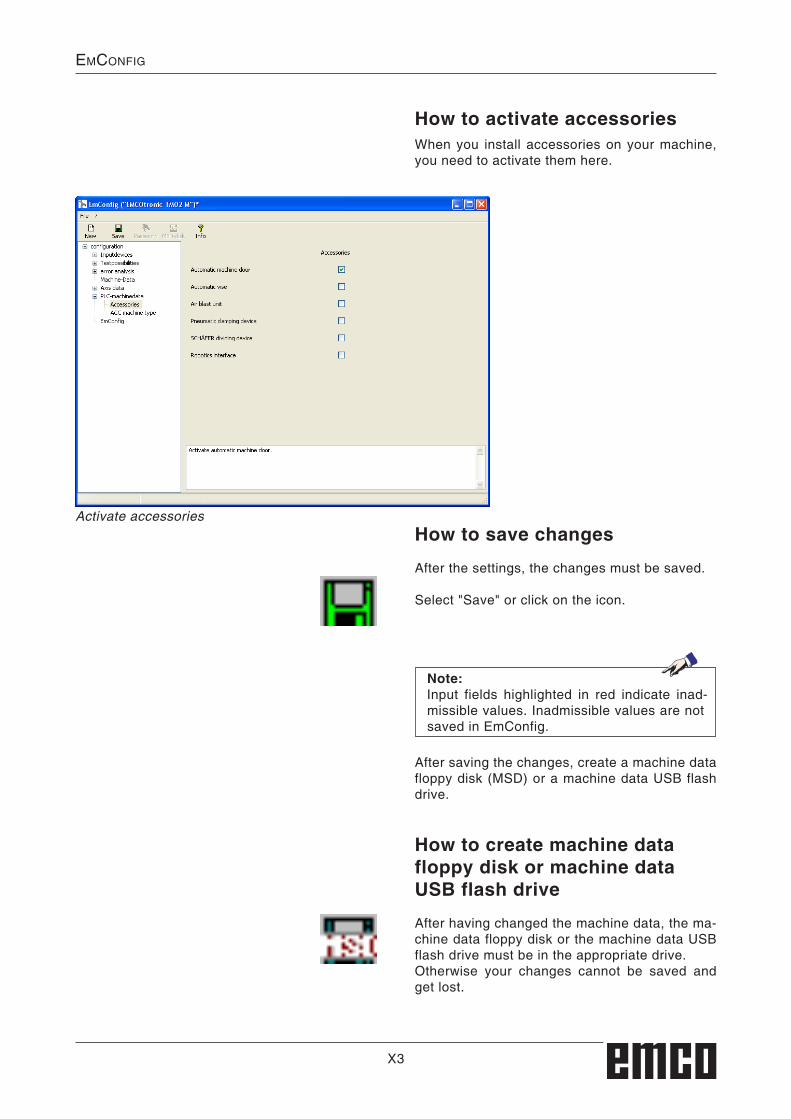
X3
emCOnFig
How to activate accessoriesWhen you install accessories on your machine, you need to activate them here.
Activate accessoriesHow to save changes
After the settings, the changes must be saved.
Select "Save" or click on the icon.
How to create machine data floppy disk or machine data USB flash drive
After having changed the machine data, the ma-chine data floppy disk or the machine data USB flash drive must be in the appropriate drive.Otherwise your changes cannot be saved and get lost.
After saving the changes, create a machine data floppy disk (MSD) or a machine data USB flash drive.
Note:Input fields highlighted in red indicate inad-missible values. Inadmissible values are not saved in EmConfig.

X4
emCOnFig

Z1
sOFtware installatiOn
Z: Software Installation Windows
Variants of WinNCYou can install EMCO WinNC for the following CNC control types:
• WinNC for SINUMERIK Operate T and M• SINUMERIK 810D/840D T and M• HEIDENHAIN TNC 426• FANUC Series 0-TC and 0-MC• FANUC Series 21 TB and MB• FAGOR 8055 TC and MC• CAMConcept T and M• EMCO EASY CYCLE T and M (except machine license)
In case there are several control types installed, a menu appears when starting EM Launch from which you can select the desired type.The following versions can be installed from the WinNC variants:
• Demo license: The demo license is valid for 30 days after the
first use. 5 days before the demo license ex-pires, you can enter another valid license key (see license manager)
• Programming station: Programming and operation of the appropriate
CNC control type is simulated by WinNC on your PC.• Single user license: Authorizes to external programming of CNC-
controlled machine tools on one PC worksta-tion (machine-independent).
• Multi-user license: Authorizes to external programming of CNC-
controlled machine tools. The multi-user li-cense can be installed on an unlimited number of PC workstations or in a network within the institute registered by the licensor (machine-independent).
• Educational license version: Is a time-limited multi-license especially for
schools and educational institutes.
• Machine license: This license allows to directly operate a PC-
controlled machine (PC TURN, Concept TURN, PC MILL, Concept MILL) of WinNC as if it was operated by an ordinary CNC control.
System prerequisites
Machine with integrated control PC:• All Concept machines• Machines that were converted to ACC• MOC with Windows XP SP3 or higher (32 / 64 Bit)
Machines with included control PC and pro-gramming stations:• PC 1000 Mhz• Windows XP SP2 or higher (32 / 64 Bit)• Working memory min. 256 MB RAM• free hard drive space 400 MB• Programming station: 1*USB, machine version:
2*USB• TCP/IP-capable network card for machine ver-
sion)
Software installation• Start Windows XP SP3 or higher• Start the installation application on the USB
stick or your download file.• Follow the instructions from the installation
guide.
For more informations regarding software instal-lation and / or software update please refer to the documentation “short description for WinNC update installation”.
Note:PC TURN and PC MILL have to be equipped with the conversion kit for ACC in order to operate EMCO WinNC.

Z2
sOFtware installatiOn
Network card (ACC)
Setting the network card for the local connection to the machine:
IP address: 192.168.10.10Subnetmask 255.255.255.0
for:Concept Turn 55Concept Mill 55Concept Turn 105 Concept Mill 105Concept Turn 60
Only for machines with ACC kit:PC Turn 50PC Mill 50PC Turn 100PC Mill 120
Network card type: TCP/IP compatible network card
Connection of the machine to the PC
In case of problems observe the instructions of your operating system (Windows help).
Danger:Removal and installation of the network card must only be carried by skilled personnel.The computer must be disconnected from the power supply (pull the power plug).
Note:During a machine installation one network-card is reserved exclusively for the control of the machine.
Instructions:If the network connection to the machine could not be established at the start, the above adjustments are to be made.

Z3
sOFtware installatiOn
Starting WinNCIf you choose AUTO START YES during the in-stallation of your machine version, WinNC starts automatically after switching on the PC.
Otherwise proceed as follows:1 Switch the machine on.
2 Wait 20 seconds to ensure that the machine operating system is running before the net-work connection to the PC is established. Otherwise it is possible that no connection can be established.
3 Switch the PC on and start Windows.
4 Click on the start symbol at the bottom.
5 Select program, EMCO and click on WinNC.
6 The start image will be shown on the screen. The license holder is registered in the start screen.
7 If you have only installed one CNC control type, it starts immediately.
8 If you have installed several CNC control types, the selection menu appears.
9 Select the desired CNC control type (cursor buttons or mouse) and press ENTER to start it.
10 If you use the control keyboard, you can select the desired CNC control type with the cursor buttons or mouse and start with the "NC-Start" button.
Terminating WinNC1 Switch off auxiliary drive with AUX OFF. Only for machine places, not for programming
stations.
2 By simultaneously pressing these buttons WinNC for Sinumerik Operate will be terminated specifically.
This corresponds to Alt+F4 on the PC keyboard.
Selection menu EMLaunch
Note:EMLaunch displays all WinNC und CAMCon-cept controls that are installed in the same directory.

Z4
sOFtware installatiOn
EMCO License Manager
Input window license key enquiry
License managerThe query in the UAC dialog box must be con-firmed with Yes in order to start the License Manager.
For the release of additional function groups of exist-ing EMCO software products it is necessary to enter a new licence key (exception: demo licence).
The EMCO License Manager (see picture on the bottom on the left) enables the input of further new license keys. For this purpose select the new product in the selection window and confirm the input.
The next time you start your control software an input window appears and asks you to enter name, address and licence key (see picture on the top left).
Please note that the licence key is asked for each software product individually. The picture on the left shows e.g. the input prompt for the licence key for the software product "Heidenhain TNC 426".
Licence inputAfter having been successfully installed, an input window appears during initial operation of an EMCO software product and asks for name, ad-dress and licence key. This input window appears for every software product installed. In case a demo licence is desired (see page Z1), please select "DEMO".Then the input window reappears only 5 days be-fore the expiry date of the demo licence. A subse-quent input of a licence key is also possible via the licence manager (see licence manager below).
Run EMCO license manager as an administrator