Embed Size (px)
Citation preview
O p e r at i O n / M a i n t e n a n c e M a n u a l
Henry Pratt ComPanyCustomer Service
401 South Highland avenueaurora, IL 60506
877.436.7977www.henrypratt.com
WARNING: 1. Read all applicable directions and instructions prior to any maintenance, troubleshooting or installation.2. Personnel involved in the installation or maintenance of valves should be constantly alert to potential emission of pipeline material and take appropriate safety precautions. Always wear suitable protection when dealing with hazardous pipeline materials. 3. Order parts from your local Pratt sales representative or directly from Henry Pratt Company. When ordering parts, please include the serial number located on the valve tag.NOTE: “WarNiNg” and “CAUTION” messages (flagged with an exclamation symbol) indicate procedures that must be followed exactly to avoid equipment damage, physical injury, or death.
!
Ballcentric® PlugValve
tabLe of ContentS PaGe
General Information 2
Installation Instructions 2-3
Operation Instructions 4-5 Maintenance 6
Troubleshooting 7
Parts Information 8-9
®
®
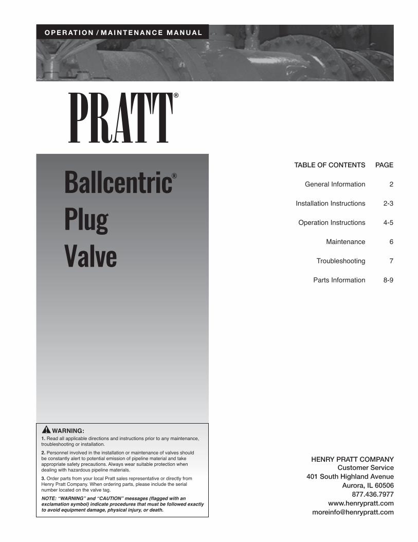
Plug valves are designed with eccentric rubber disc seating surfaces. The plug rotates 1/4 turn to provide shutoff in pipes. The eccentric seating action provides for tighter shutoff as the actuator is adjusted to provide for more rotation. The valve can be adjusted to a maximum of 10 degrees over travel. The valves can be used to regulate flow rate by positioning the plug between 15 and 90 degrees open.
Manually operated plug valves are powered with one of the following: 2” direct nut, lever handle or gear actuators, which convert multiple handwheel, chainwheel, or nut input turns into 1/4 turn valve operation. The travel of the valve plug is limited by physical stops in the torque collar for wrench operated valves. CAUTION: Forcing the handwheel, chainwheel or nut against the stops will not provide tighter shutoff of the valve and may damage the actuator. Only actuator adjustments will affect valve shutoff.
Ballcentric® Plug ValveGeneral Information / Installation
2
Functional Description
Motor Operated Valve Motor operated valves are powered with gear actuators, which convert multiple motor input turns into 1/4 turn valve operation. The travel of the valve plug is limited by limit switches in the motor housing and physical stop in the actuator housing. Valve shutoff is affected by limit switch and physical stop settings. CAUTION: Improperly set limit switches and/or physical stops may damage the motor and/or actuator.
Hydraulically operated valves are powered with a gear box and double acting cylinder. The linear stroke of the cylinder is converted to 1/4 turns operation by the gear box. Auxiliary controls are provided to direct hydraulic power to the cylinder and to control the operating speed of the cylinder.
When installing the plug valves, the seat end should be noted. The seat end of the valve is cast in raised letters on the appropriate flange of the valve. Generally, straightway valves should be installed with the highest pressure applied from the opposite end from the seat. This will tend to push the plug into the seat On pump discharge installations the seat end should be towards the pump.In cases where shut-off is required in both directions, the valve should be installed so that the highest differential pressure at shut-off is opposite the seat end.
When the service is of a clogging type, with suspended solids likely to build up in the valve body, it is recommended that the valve be installed with the media entering the seat end first. In extreme cases, the valve should be installed with the plug horizontal and rotating upward into the top portion of the valve body cavity to open. See Page 6 for recommended installation options.Class 125 flanged end valves have ANSI B16.1 flat faced 125/150 flanges. Standard ANSI B16.21 flanges and gaskets should be used to install the valves in the pipeline.
Certain size valves utilize tapped holes on the top and bottom of the flange where a backing nut is not possible. Please check specific drawings for detailed information on sizes and quantities of hexagon head screws required on these valves.Prior to installing valves, they should be cycled open and closed several times to ensure they are in good working order and have not been damaged during shipment or storage.
installation
!
!
Ballcentric® Plug ValveInstallation
3
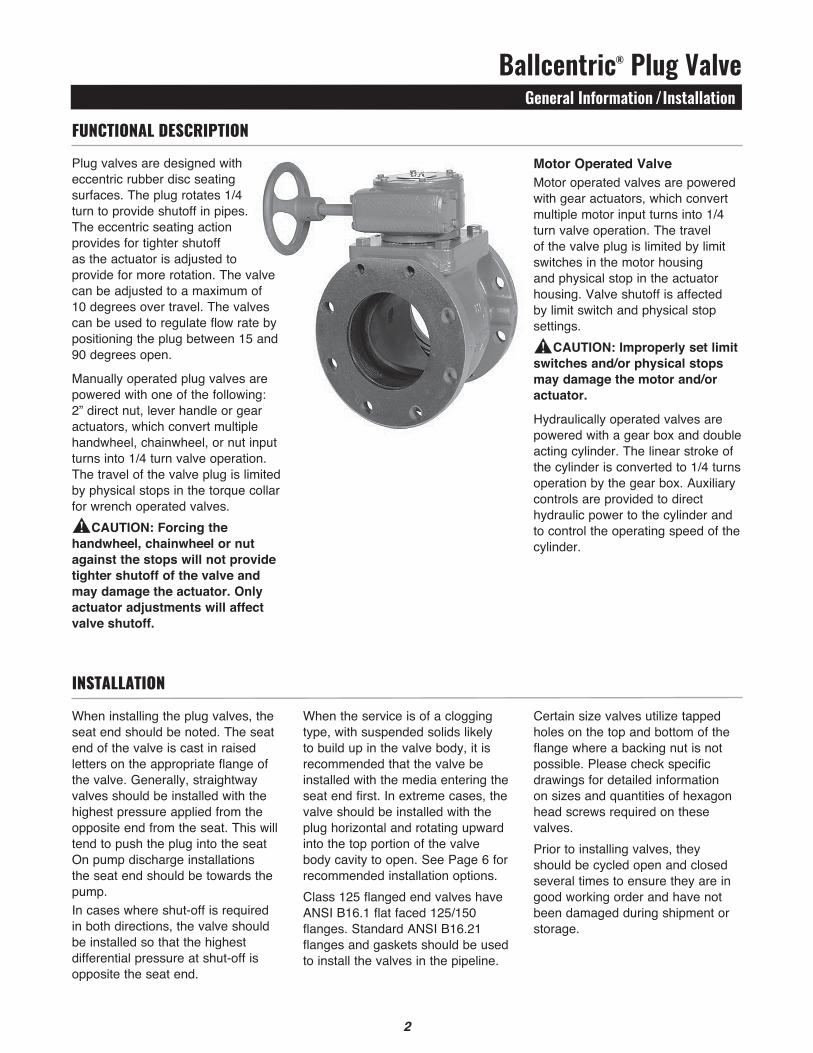
The type of materials carried in the pipeline and the location of the valve determine the correct installation orientation.
Liquids Without Suspended SolidsValve may be installed with plug shaft vertical or horizontal. For vertical pipe installations, install valve with seat facing downstream.Before installation, blow out pipeline to remove all foreign materials.
Suspended Solids and Dirty GasesInstall valve with plug facing upstream. Ensure plug rotates up to the fully open position thus preventing plug from sweeping through settled debris. NOTE: For pump isolation service install the discharge valve with the seat downstream from the pump and with the plug rotating to the top of the pipeline in the open position.
installation options
Liquids without suspended soLidsDownstream
Upstream
Pump
FLow
seat side
FLow
seat side
FLow
Upstream
Downstream
suspended soLids and dirty gases
Shut
Pump
FLow
seat side
FLow
FLow
Upstream
Open
seat side
seat sideDownstream
NOTE: When installing valve horizontal (shaft in horizontal position) make sure plug is located on top side of valve when in open position.
wrench operated VaLVe with torque coLLar
Ballcentric® Plug ValveOperation
4
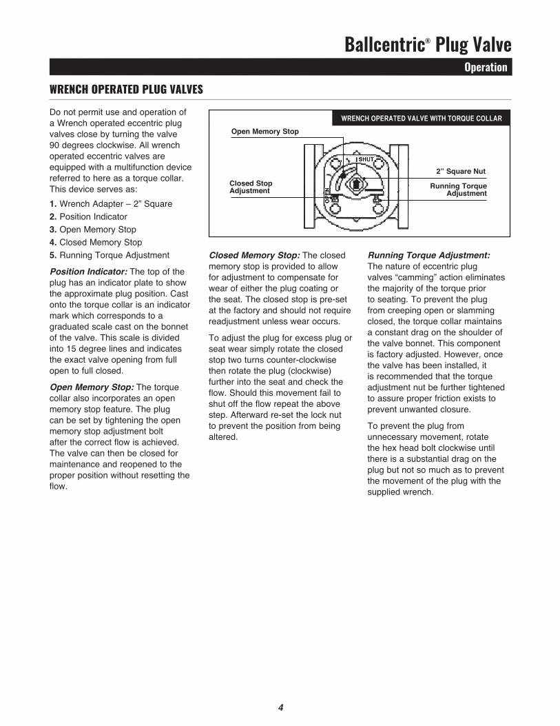
Do not permit use and operation of a Wrench operated eccentric plug valves close by turning the valve 90 degrees clockwise. All wrench operated eccentric valves are equipped with a multifunction device referred to here as a torque collar. This device serves as:1. Wrench Adapter – 2” Square2. Position Indicator3. Open Memory Stop4. Closed Memory Stop5. Running Torque Adjustment
Position Indicator: The top of the plug has an indicator plate to show the approximate plug position. Cast onto the torque collar is an indicator mark which corresponds to a graduated scale cast on the bonnet of the valve. This scale is divided into 15 degree lines and indicates the exact valve opening from full open to full closed.
Open Memory Stop: The torque collar also incorporates an open memory stop feature. The plug can be set by tightening the open memory stop adjustment bolt after the correct flow is achieved. The valve can then be closed for maintenance and reopened to the proper position without resetting the flow.
Closed Memory Stop: The closed memory stop is provided to allow for adjustment to compensate for wear of either the plug coating or the seat. The closed stop is pre-set at the factory and should not require readjustment unless wear occurs.
To adjust the plug for excess plug or seat wear simply rotate the closed stop two turns counter-clockwise then rotate the plug (clockwise) further into the seat and check the flow. Should this movement fail to shut off the flow repeat the above step. Afterward re-set the lock nut to prevent the position from being altered.
Running Torque Adjustment: The nature of eccentric plug valves “camming” action eliminates the majority of the torque prior to seating. To prevent the plug from creeping open or slamming closed, the torque collar maintains a constant drag on the shoulder of the valve bonnet. This component is factory adjusted. However, once the valve has been installed, it is recommended that the torque adjustment nut be further tightened to assure proper friction exists to prevent unwanted closure.
To prevent the plug from unnecessary movement, rotate the hex head bolt clockwise until there is a substantial drag on the plug but not so much as to prevent the movement of the plug with the supplied wrench.
Wrench operateD plug ValVes
5
Closed Stop Adjustment
Open Memory Stop
2” Square Nut
Running Torque Adjustment
gear operated pLug VaLVes
Ballcentric® Plug ValveOperation
5
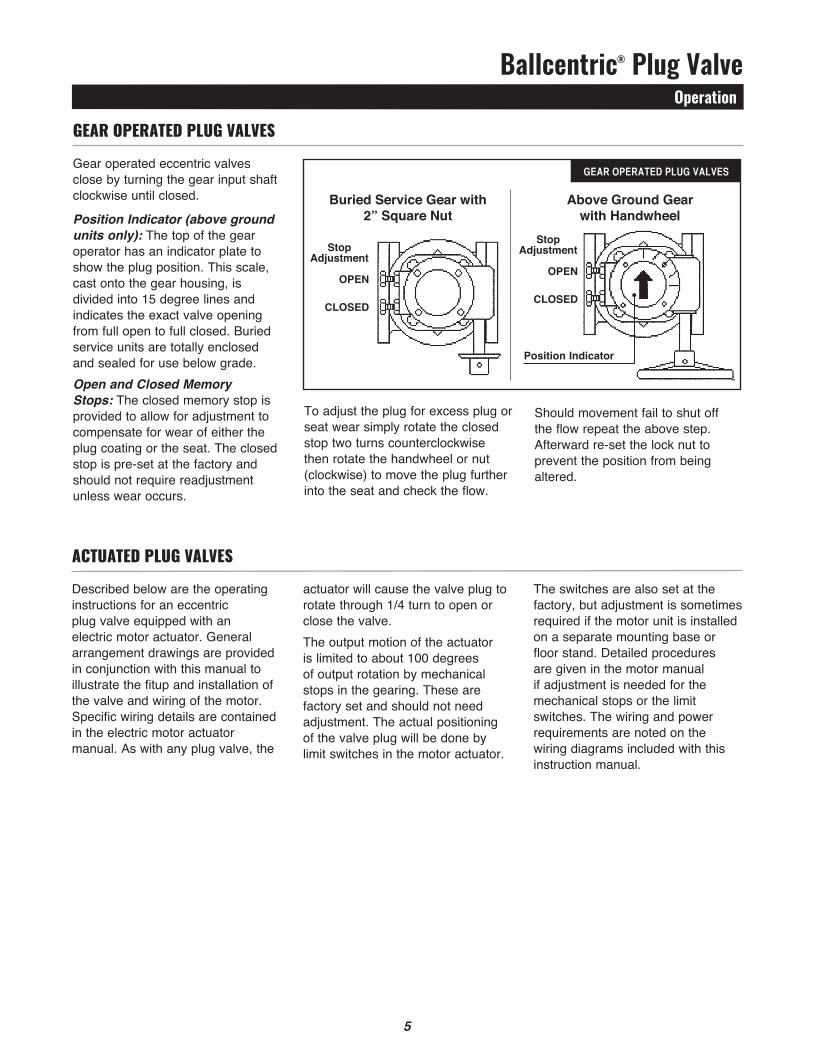
Gear operated eccentric valves close by turning the gear input shaft clockwise until closed.
Position Indicator (above ground units only): The top of the gear operator has an indicator plate to show the plug position. This scale, cast onto the gear housing, is divided into 15 degree lines and indicates the exact valve opening from full open to full closed. Buried service units are totally enclosed and sealed for use below grade.Open and Closed Memory Stops: The closed memory stop is provided to allow for adjustment to compensate for wear of either the plug coating or the seat. The closed stop is pre-set at the factory and should not require readjustment unless wear occurs.
To adjust the plug for excess plug or seat wear simply rotate the closed stop two turns counterclockwise then rotate the handwheel or nut (clockwise) to move the plug further into the seat and check the flow.
Should movement fail to shut off the flow repeat the above step. Afterward re-set the lock nut to prevent the position from being altered.
gear operateD plug ValVes
Described below are the operating instructions for an eccentric plug valve equipped with an electric motor actuator. General arrangement drawings are provided in conjunction with this manual to illustrate the fitup and installation of the valve and wiring of the motor. Specific wiring details are contained in the electric motor actuator manual. As with any plug valve, the
actuator will cause the valve plug to rotate through 1/4 turn to open or close the valve.The output motion of the actuator is limited to about 100 degrees of output rotation by mechanical stops in the gearing. These are factory set and should not need adjustment. The actual positioning of the valve plug will be done by limit switches in the motor actuator.
The switches are also set at the factory, but adjustment is sometimes required if the motor unit is installed on a separate mounting base or floor stand. Detailed procedures are given in the motor manual if adjustment is needed for the mechanical stops or the limit switches. The wiring and power requirements are noted on the wiring diagrams included with this instruction manual.
actuateD plug ValVes
Buried Service Gear with2” Square Nut
Above Ground Gearwith Handwheel
StopAdjustment
OPEN
CLOSED
StopAdjustment
OPEN
CLOSED
Position Indicator
Ballcentric® Plug ValveMaintenance
6
The eccentric valve is designed and manufactured to be a long life valve under normal circumstances. It does not require any routine maintenance. Cycling the valve from full open to full closed on an annual basis will increase the life of the valve and operator components. However, if maintenance is required due to unusual wear or service conditions, the following procedure should be followed: CAUTION: Valve should be depressurized for all maintenance activitiesDisassembly ProcedureBody: The plug valve is a top entry valve; therefore the body can remain in line during this operation.Gear Operated Valves: Remove the bolts holding the gear operator housing cover in place. Remove the housing cover and the internal bolts holding the gear operator to the valve body. Remove the gear operator and set aside.Wrench Operated Valves: Remove the star washer fastening the torque collar to the plug stem. Remove the torque collar and set aside. With the valve de-pressurized, remove the hexagonal head cap screws that hold the bonnet to the valve body.
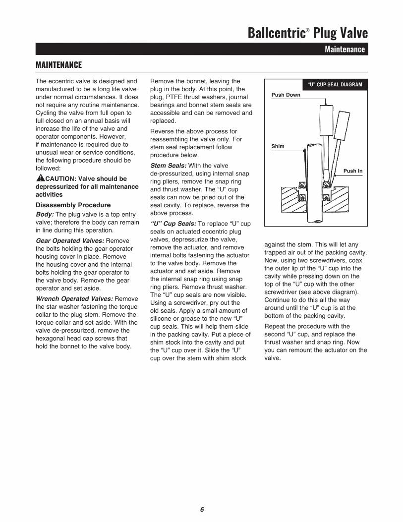
Remove the bonnet, leaving the plug in the body. At this point, the plug, PTFE thrust washers, journal bearings and bonnet stem seals are accessible and can be removed and replaced.Reverse the above process for reassembling the valve only. For stem seal replacement follow procedure below.Stem Seals: With the valve de-pressurized, using internal snap ring pliers, remove the snap ring and thrust washer. The “U” cup seals can now be pried out of the seal cavity. To replace, reverse the above process.“U” Cup Seals: To replace “U” cup seals on actuated eccentric plug valves, depressurize the valve, remove the actuator, and remove internal bolts fastening the actuator to the valve body. Remove the actuator and set aside. Remove the internal snap ring using snap ring pliers. Remove thrust washer. The “U” cup seals are now visible. Using a screwdriver, pry out the old seals. Apply a small amount of silicone or grease to the new “U” cup seals. This will help them slide in the packing cavity. Put a piece of shim stock into the cavity and put the “U” cup over it. Slide the “U” cup over the stem with shim stock
against the stem. This will let any trapped air out of the packing cavity. Now, using two screwdrivers, coax the outer lip of the “U” cup into the cavity while pressing down on the top of the “U” cup with the other screwdriver (see above diagram). Continue to do this all the way around until the “U” cup is at the bottom of the packing cavity.Repeat the procedure with the second “U” cup, and replace the thrust washer and snap ring. Now you can remount the actuator on the valve.
Maintenance
!
“u” cup seaL diagram
Push Down
Shim
Push In
6
Ballcentric® Plug ValveTroubleshooting
7
troubleshooting
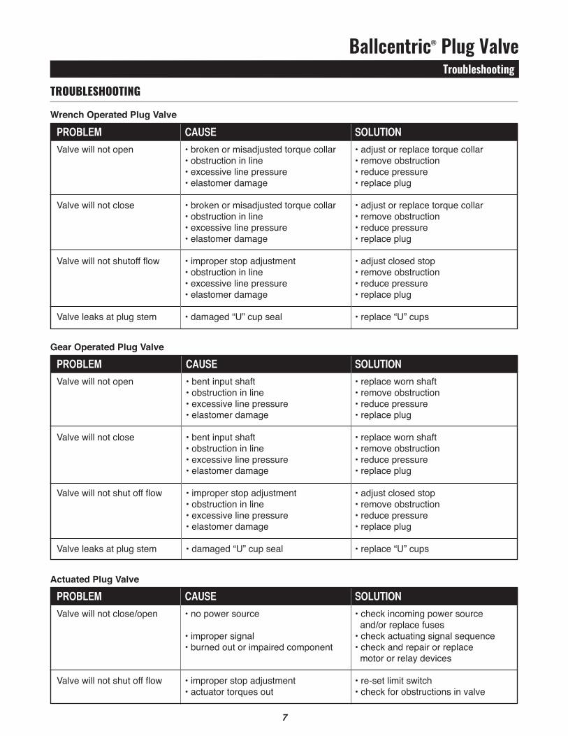
Wrench Operated Plug Valve
Actuated Plug Valve
Gear Operated Plug Valve proBLem cause soLution Valve will not open • bent input shaft • replace worn shaft • obstruction in line • remove obstruction • excessive line pressure • reduce pressure • elastomer damage • replace plug
Valve will not close • bent input shaft • replace worn shaft • obstruction in line • remove obstruction • excessive line pressure • reduce pressure • elastomer damage • replace plug
Valve will not shut off flow • improper stop adjustment • adjust closed stop • obstruction in line • remove obstruction • excessive line pressure • reduce pressure • elastomer damage • replace plug
Valve leaks at plug stem • damaged “U” cup seal • replace “U” cups
proBLem cause soLution Valve will not close/open • no power source • check incoming power source and/or replace fuses • improper signal • check actuating signal sequence • burned out or impaired component • check and repair or replace motor or relay devices
Valve will not shut off flow • improper stop adjustment • re-set limit switch • actuator torques out • check for obstructions in valve
proBLem cause soLution Valve will not open • broken or misadjusted torque collar • adjust or replace torque collar • obstruction in line • remove obstruction • excessive line pressure • reduce pressure • elastomer damage • replace plug
Valve will not close • broken or misadjusted torque collar • adjust or replace torque collar • obstruction in line • remove obstruction • excessive line pressure • reduce pressure • elastomer damage • replace plug
Valve will not shutoff flow • improper stop adjustment • adjust closed stop • obstruction in line • remove obstruction • excessive line pressure • reduce pressure • elastomer damage • replace plug
Valve leaks at plug stem • damaged “U” cup seal • replace “U” cups
8
2
5
3
15
14
13
126
5
9
1
6
7
11
16
10
18
14
19
17
14
19
14 14
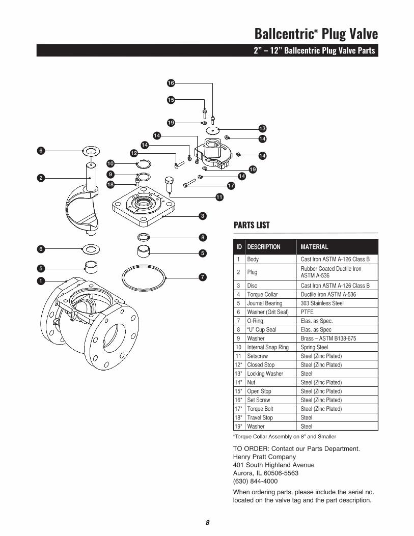
TO ORDER: Contact our Parts Department. Henry Pratt Company401 South Highland AvenueAurora, IL 60506-5563(630) 844-4000 When ordering parts, please include the serial no. located on the valve tag and the part description.
Ballcentric® Plug Valve2” – 12” Ballcentric Plug Valve Parts
8
parts list
*Torque Collar Assembly on 8” and Smaller
id description materiaL
1 Body CastIronASTMA-126ClassB
2 Plug
RubberCoatedDuctileIron
ASTMA-536
3 Disc CastIronASTMA-126ClassB
4 TorqueCollar DuctileIronASTMA-536
5 JournalBearing 303StainlessSteel
6 Washer(GritSeal) PTFE
7 O-Ring Elas.asSpec.
8 “U”CupSeal Elas.asSpec
9 Washer Brass–ASTMB138-675
10 InternalSnapRing SpringSteel
11 Setscrew Steel(ZincPlated)
12* ClosedStop Steel(ZincPlated)
13* LockingWasher Steel
14* Nut Steel(ZincPlated)
15* OpenStop Steel(ZincPlated)
16* SetScrew Steel(ZincPlated)
17* TorqueBolt Steel(ZincPlated)
18* TravelStop Steel
19* Washer Steel
7
2
5
12
5
4
9
1
4
7
1011
3
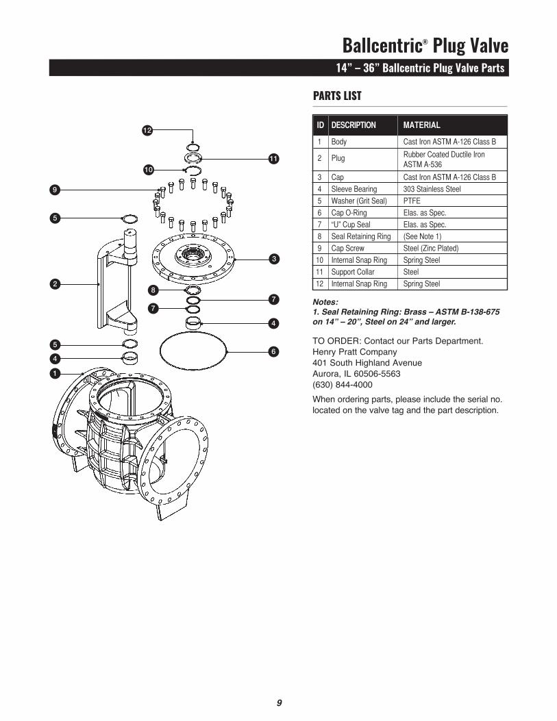
TO ORDER: Contact our Parts Department. Henry Pratt Company401 South Highland AvenueAurora, IL 60506-5563(630) 844-4000 When ordering parts, please include the serial no. located on the valve tag and the part description.
Ballcentric® Plug Valve14” – 36” Ballcentric Plug Valve Parts
9
parts list
Notes:1. Seal Retaining Ring: Brass – ASTM B-138-675 on 14” – 20”, Steel on 24” and larger.
8
6
id description materiaL
1 Body CastIronASTMA-126ClassB
2 Plug RubberCoatedDuctileIron ASTMA-536
3 Cap CastIronASTMA-126ClassB
4 SleeveBearing 303StainlessSteel
5 Washer(GritSeal) PTFE
6 CapO-Ring Elas.asSpec.
7 “U”CupSeal Elas.asSpec.
8 SealRetainingRing (SeeNote1)
9 CapScrew Steel(ZincPlated)
10 InternalSnapRing SpringSteel
11 SupportCollar Steel
12 InternalSnapRing SpringSteel

Henry Pratt [email protected]
Form 13810 - 02/17
Copyright © 2017 Henry Pratt Company, LLC. All Rights Reserved.The trademarks, logos and service marks displayed in this document herein are the property of Henry Pratt Company, LLC, its affiliates or other third parties. Products marked with a section symbol (§) are subject to patents or patent applications. For details, visit www.mwppat.com. These products are intended for use in potable water or wastewater applications. Please contact your Henry Pratt Company Sales or Customer Service Representative concerning any other application(s).
Reliable ConnectionsTM
International1.423.490.9555www.mueller-international.cominternational@muellercompany.com