Embed Size (px)
Citation preview

Operation Maintenance Manual
Model: F-500/800/1000 Mud Pump
SHENGLI OILFIELD SHENGQING PETROLEUM EQUIPMENT CO.,LTD
NO.676 Yellow River Road, Dongying,Shandong ,China
Tel:0086-0546-8550456 Cel:0086-18561211527
Email:[email protected] Skype:[email protected]
Website:http://www.sqsyjx.com/

Instruction Manual for F-500/800/1000 Mud Pump
I
TABLE OF CONTENTS
F-500/800/1000 SLURRY PUMP
SECTION TETLE
1 F-500/800/1000 SLURRY PUMP OPERATION
& MAINTENANCE MANUAL
2 F-500/800/1000 SLURRY PUMP PARTS BOOK
3 KB-45/75 PULSATION DAMPENER PARTS BOOK
4 JA-3 SHEAR RELIEF VALVE PARTS BOOK

Instruction Manual for F-500/800/1000 Mud Pump
1
1. F-500/800/1000 TRIPLEX PUMP OPERATION
& MAINTENANCE MANUAL
1. TECHNICAL DATA
General dimensions Specifications Parameter Data 2. INSTALLATION OF NEW PUMP
2.1 Setting The Pump 2.2 Land Installations 2.3 Permanent Installations 2.4 Installations of The Drive 2.5 Suction System 2.6 Power End 2.7 Piston and Liner Cooling System 2.8 Fluid End Assembly F-500/800/1000 2.9 Accessory Manifold 3. LUBRICATION
3.1 Minimum Operating Speeds 3.2 Controlled Flow Splash System 3.3 Total Pressure Lubrication System 3.4 Maintenance of Lubrication System 4. MAINTENANCE
4.1 Power End 4.2 Roller Bearings 4.3 Pinion Shaft Assembly 4.4 Crankshaft Assembly 4.5 Installing Crankshaft Assembly in Frame 4.6 Installation of Crosshead Guides For F-800/1000 4.7 Installation of Crosshead Guide For F-500 4.8 Installation of Crossheads 4.9 Checking Crosshead Alignment 4.10 Fluid End Maintenance 4.11 Welding and Repairs 4.12 Repairs to Valve Pot Cover Bore 4.13 Operating Maintenance 4.14 Troubleshooting 5. APPROXIMATE WEIGHT OF PUMP ASSEMBLIES
6. STORAGE
Instruction Manual for F-500/800/1000 Mud Pump
2
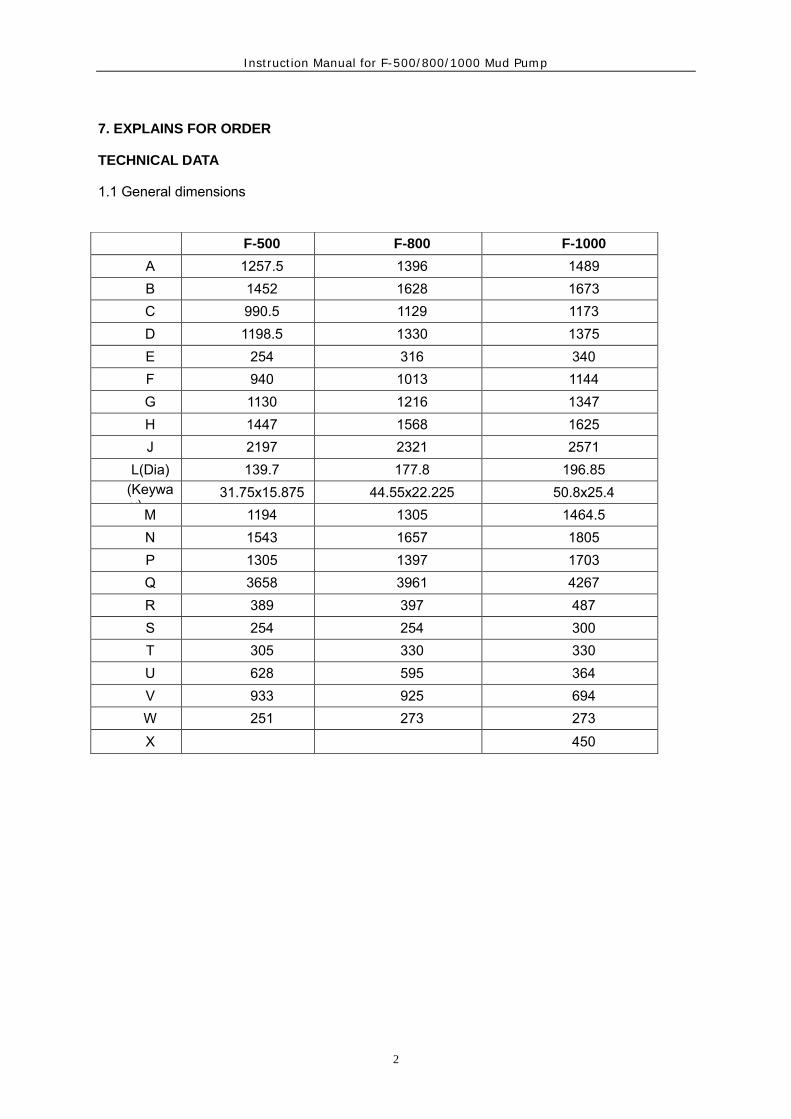
7. EXPLAINS FOR ORDER
TECHNICAL DATA
1.1 General dimensions
F-500 F-800 F-1000
A 1257.5 1396 1489 B 1452 1628 1673 C 990.5 1129 1173 D 1198.5 1330 1375 E 254 316 340 F 940 1013 1144 G 1130 1216 1347 H 1447 1568 1625 J 2197 2321 2571
L(Dia) 139.7 177.8 196.85 (Keyway)
31.75x15.875 44.55x22.225 50.8x25.4 M 1194 1305 1464.5 N 1543 1657 1805 P 1305 1397 1703 Q 3658 3961 4267 R 389 397 487 S 254 254 300 T 305 330 330 U 628 595 364 V 933 925 694 W 251 273 273 X 450

Instruction Manual for F-500/800/1000 Mud Pump
3
Fig.1

Instruction Manual for F-500/800/1000 Mud Pump
4
1.2 Specification
Model F-500 F-800 F-1000
Type Triplex single acting
piston pump
Triplex single acting
piston pump
Triplex single acting
piston pump
Size,Maximum Bore X
Sroke
170X191MM
(6.6930”X7.5”)
170X229MM
(6.6930”X9”)
170X254MM
(6.6930”X10”)
Speed Rating 165SPM 150SPM 140SPM
House Power Rating 370KW(500HP) 590KW(800HP) 735KW(1000)HP
Type Geae Herringbone Herringbone Herringbone
Gear Rating 4.286:1 4.185:1 4.207:1
Lubrication Pressure & Splash Pressure & Splash Pressure & Splash
Suction Inlet 8” Flange (203mm
Approx)
10” Flange (254mm
Approx)
12” Flange
(305mm Approx)
Discharge Outlet
103mm,35mpa
4”Flang,1500ANSI
5000API
130mm,35mpa
5”Flang,1500ANSI
5000API
130mm,35mpa
5”Flang,1500ANSI
5000API
Pinion Shaft Size 139.7mm( 5 1/2”) 177.8mm( 7”) 196.9mm( 7 3/4”)
Keys 31.75x31.75mm (1
1/4”x1 1/4”)
44.45x44.45mm (1
3/4”x1 3/4”)
50.8x50.8mm
(2”x2”)
Valve Pots Valve Over Valve
API 5#
Valve Over Valve API
6#
Valve Over Valve
API 6#
Valve Cover Screw Type Screw Type Screw Type
Cylinder Head Screw Type Screw Type Screw Type
Liner Lock Screw
Type,Metal-Tometal
Screw
Type,Metal-Tometal
Screw
Type,Metal-Tometa
Weights kg 9770kg 14500kg 18790kg

Instruction Manual for F-500/800/1000 Mud Pump
1
Performance Data
Performance Data F-500 Pump
STROK
E
PER MINUT
E
HORSEPOWE
R
RATING
Mpa
LINER SIZE(mm) AND PRESSURE RATING (Mpa.kgf/cm2)
170 160 150 140 130 120 110 100
9.2 10.4 11.8 13.6 15.8 18.6 22.1 26.2
KW HP VOLUME-LITERS PER SECOND
175 392 530 37.8 33.5 29.4 25.7 22.1 18.8 15.8 13.0
165 370 500 35.6 31.6 27.7 24.2 20.8 17.7 14.9 12.3
150 336 455 32.7 28.7 25.2 22.0 18.9 16.1 13.5 11.2
140 314 424 30.2 26.8 23.5 20.5 17.6 15.0 12.6 10.4
120 269 364 25.9 23.0 20.1 17.6 15.1 12.9 10.8 8.9
100 224 303 21.6 19.2 16.8 14.7 12.6 10.7 9.0 7.5
1 0.216 0.192 0.168 0.147 0.126 0.107 0.09 0.075

Instruction Manual for F-500/800/1000 Mud Pump
1
Performance Data F-800 Pump
STROK
E
PER MINUT
E
HORSEPOWE
R
RATING
Mpa
LINER SIZE(mm) AND PRESSURE RATING (Mpa.kgf/cm2)
170 160 150 140 130
13.64 15.40 17.52 20.11 23.33
KW HP VOLUME-LITERS PER SECOND
165 629 853 41.51 36.78 32.32 28.16 24.28
150 590 800 38.92 34.48 30.30 26.40 22.76
140 551 747 36.33 32.18 28.28 24.64 21.24
130 511 693 33.73 29.88 26.26 22.88 19.73
120 472 640 31.14 27.58 24.24 21.12 18.21
100 433 587 28.54 25.28 22.22 19.36 16.69
1 0.259 0.23 0.202 0.176 0.152

Instruction Manual for F-500/800/1000 Mud Pump
2
Performance Data F-1000 Pump
STROK
E
PER MINUT
E
HORSEPOWE
R
Mpa
LINER SIZE(mm) AND PRESSURE RATING (Mpa.kgf/cm2)
170 160 150 140 130
16.46 18.59 21.18 24.27 28.19
KW HP VOLUME-LITERS PER SECOND
150 791 1070 43.26 38.30 33.62 29.33 25.25
140 738 1000 40.39 35.76 31.39 27.39 23.58
130 686 929 37.52 33.22 29.16 25.45 21.91
120 646 875 35.34 31.29 27.47 23.97 20.63
110 580 786 31.75 28.11 24.67 21.53 18.53
100 527 714 28.84 25.53 22.41 19.56 16.84
1 0.2884 0.2553 0.2241 0.1956 0.1684
Instruction Manual for F-500/800/1000 Mud Pump
1
2. INSTALLATION OF NEW PUMP
Your F-series pumps has been completely assembled and test operated under pressure
before being shipped to the field. Unless otherwise instructed, the lubrication is drained form
the power end. Before putting the pump into service, the following precautions and
operations must be performed or checked.
In order to prevent personal injury during the performance of any maintenance or
inspection procedures, this equipment MUST BE SHUT DOWN AND NOT OPERATION,
and all safety devices on prime movers, drives, etc., MUST BE IN THE SAFE POSITION.
2.1 Setting The Pump
The skid under the pumps manufactured by our company is suitable for most any type of
installation . It should be noted , however, that the box type construction of the power frame has
high resistance to bending but relatively less resistance against twist. Therefore, the support
under the pump must be level and adequate to support the weight and operating forces exerted
by the pump.
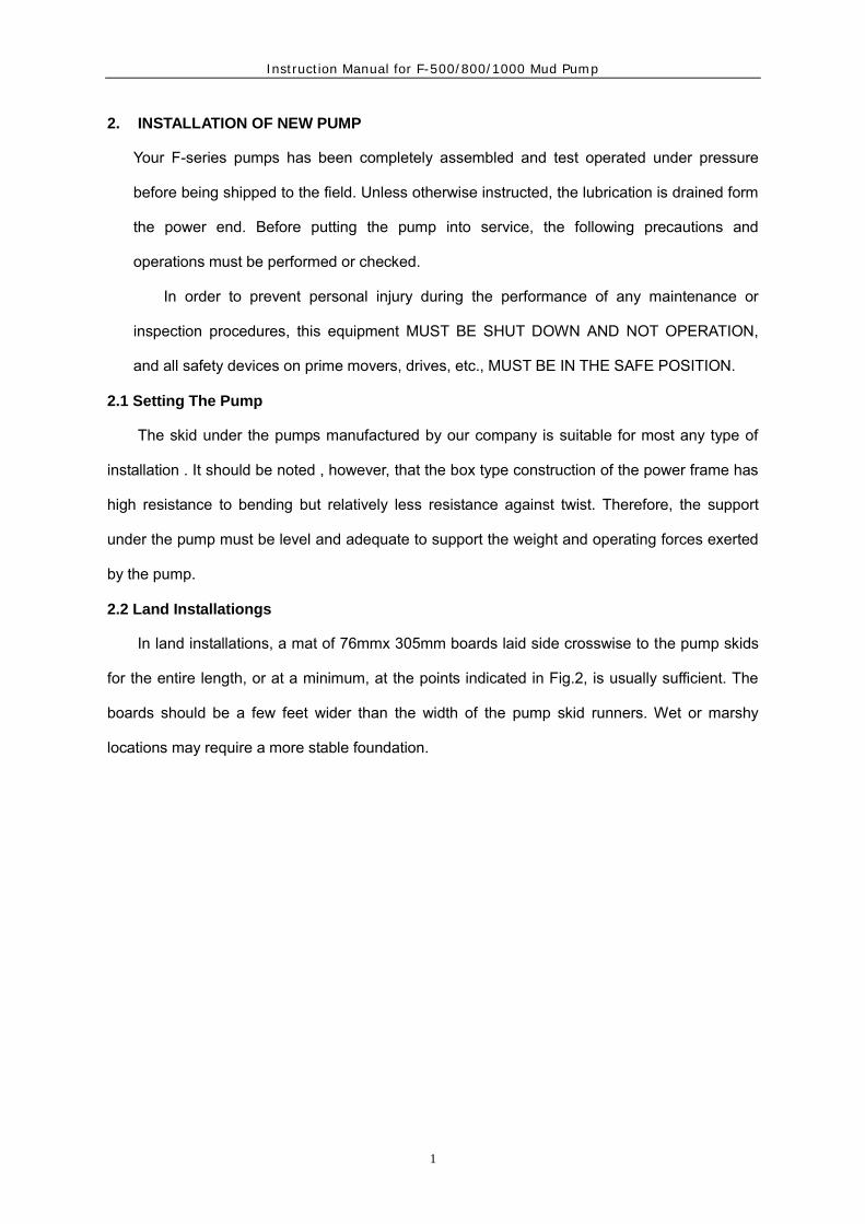
2.2 Land Installationgs
In land installations, a mat of 76mmx 305mm boards laid side crosswise to the pump skids
for the entire length, or at a minimum, at the points indicated in Fig.2, is usually sufficient. The
boards should be a few feet wider than the width of the pump skid runners. Wet or marshy
locations may require a more stable foundation.

Instruction Manual for F-500/800/1000 Mud Pump
2
Fig. 2
2.3 Permanent Installations
On permanent installations such as barge, platform, structural base, or concrete slab, where pump skids are bolted down, it is essential that the skids be properly shimmed to prevent possibility of twisting or distorting the power frame. The pump skids must sit solid on all shim points with bolts loose. On barge installations, the pump skids are generally bolted down to T-beams running parallel and in line with the pump skids. Install shims at points shown in Fig, 2 and 3 and observe caution of proper shimming to prevent twist or distortion. The shims on all installations should extend the full width of the skid beam flanges and have a minimum length of 12″ (305mm). On installations where the power unit or electric motor is mounted integrally with the pump skids, the preferred installation would be to set the pump package on the T-beam skids and provide retention blocks rather than bolts to hold it in place. This will allow the pump to “float” and minimize the transfer of barge deck or platform distortion into the frame.

Instruction Manual for F-500/800/1000 Mud Pump
3
Fig. 3
2.4 Installation of The Drive
The drive between the mud pumps and the power source, whether V-belts or multiwidth chains, should be installed with the greatest care to assure maximum operating life with minimum of unexpected shutdowns due to drive failures. When installing the drive sheave or sprocket, make sure all grease or rust preventative is removed from the shaft and the bore of the drive. Remove all burrs or rough spots from the shaft, key, and keyway. Fit key to the keyways in both the shaft and drive and install key into shaft keyway. Coat pinion shaft with a light coating of anti-adhesive compound or light oil and install the drive sheave or sprocket hub. Tighten hub bolts as indicated below: When a wrench or length of pipe is used to increase leverage in tightening draw-up bolts, it is imperative to adhere to the wrench torque values given in the chart below. This adherence is important, because in mounting the hub, the tightening force on the bolts is multiplied many times by the wedging action of the tapered surface. This action compresses the hub for a snug fit on the shaft. If the bolt-tightening forces are extreme, bursting pressure is created in the hub of the mounted pulley, this pressure may cause the pulley to crack. The hub bolts should always be tightened alternately and progressively.
Pump Type QD Hub*
Wrench Torque N.m Wrench Length mm Wrench pull N
F-500 N 406 760 534

Instruction Manual for F-500/800/1000 Mud Pump
4
F-800 P 610 760 800
F-1000 W 813 900 900
*Refer To Eaton Transmission Products Catalog For QD Busing Size
2.4.1 V-Belt Drives a) Check sheave groove condition Before installing the v-belts, check sheave grooves for wear, worn or rounded grooves will destroy V-belts rapidly. The side walls must be straight. In sheave grooves must be free of dirt, rust or other extrusions, which could damage the V-belts. b) check sheave alignment The final alignment of the V-belt sheaves should be checked after the V-belts have been installed and adjusted to their operating tension. If the sides of the sheaves are of equal distance from the centerline 1 of the groove, check alignment by stretching TWO strings (fish line or piano wire preferred) along one side of the two sheaves, one above and one below the centerline, and moving one of the sheaves until the strings touch four points on the side of the sheave rims. This will determine that the centerline of the drives are parallel and the faces of the sheaves are square. c) Adjust V-belt for previous tension Adjust the belt tension by moving the sheaves apart until all of the sag has just been eliminated from the tight side of the belt and some of the belts on the slack side. Then increase the centers approximately 13mm( 1/2”) for each 2540mm( 100”) Center distance. Example: On 3180mm(150”) center, move pump and additional 19.5mm( 3/4”)
DO NOT OBTAIN BELT TENSION BY PICKING UP END OF PUMP AND ALLOWING BELTS
TO TIGHTEN UNDER WEIGHT OF PUMP AS END IS BEING LOWERED TO THE GROUND. 2.4.2 Chain Drives a) Installation Proper installation and maintenance of the sprocket and chain drives are essential if good service life is to be obtained. Since many factors, such as chain width, center distances, speeds, and loads must be considered when determining the allowable tolerance for sprocket alignment; no good “rule of thumb” can be applied. The chain alignment must simply be held as nearly

Instruction Manual for F-500/800/1000 Mud Pump
5
perfect as possible. A more precise alignment can be made by stretching two steel wires (piano wire) along one face of the two sprockets, one above and one below the centerline, and moving one of the sprockets until the wires touch at four points. This will determine that the centerlines of the drives are parallel and the faces of the sprockets are square. b) Drive chain lubrication The pump drive chain lubrication system on the majority of F series of pumps is an independent system having its own oil pump, reservoir and drive. Fill chain case to the indicated level with a non-detergent oil as follows: Ambient temperature above 32º F(0ºC) SAE-30 Ambient temperature below 32º F(0ºC) SAE-20 For temperatures below 0ºF,consult a reputable lubrication dealer for recommendations. RRFER TO GENERAL LUBRICATION BULLETIN for approved lubricants and additional specifications. If any discrepancy exists between the recommendations in this manual and the General Lubrication Bulletin, those in the Lubrication Bulletin will take precedence. Since this is an independent system, it will require the same maintenance or service attention employed on any other piece of machinery, including: Daily check of oil level. Daily check on condition of oil. Frequent Check on oil pressure. (5-15psi) (0.352-1.06kg.cm2). Volume of oil being applied to chain. Condition of nozzles in spray tube. Condition of oil pump drive (V-belts or chain)
NOTE:
1. Oil pressure may be adjusted with the pressure relief adjusting screw on the rear of the
pump housing.
2. Pressure drops may also indicate suction and discharge filter screens need cleaning.
2.5 Suction System Requirements
Individual installation conditions will dictate the design of the suction system. The suction of the F-series pumps must have a positive head (pressure) for satisfactory performance. The optimum suction manifold pressure is 20-30 psi (0.14-0.21Mpa) for maximum volumetric efficiency and expendable parts life. This head pressure is best supplied by a 5x6 centrifugal pump with 40h.p 1150 rpm electric motor. This type of drive requires a device to automatically start and stop the centrifugal pump motor simultaneously with the triplex pump. On DC electric powered a signal can usually be supplied from the DC control panel to energize a magnetic starter when the mud pump clutch air line will provide a set of contacts for energizing the magnetic starter when clutch is engaged.

Instruction Manual for F-500/800/1000 Mud Pump
6
The charging pump can also be belt driven from the triplex pinion shaft charging type of drive is not as efficient at slow speeds with viscous fluids. Under some conditions the F-Series pumps may be operated without a charging pump, provided the fluid level in mud pits is higher than the top of the liners, fluid being pumped is low viscosity and suction line must be short, straight and of at least the same diameter as suction manifold inlet. The suction lines should be piped with valve arrangements so the charging pump can be by-passed so operation can be continued in event of charging pump failure or for maintenance. Operation without a charging pump can be improved by replacing the suction valve spring with a weaker spring. Suction dampener is a very effective aid for complete filling of the liners and dampening pulsations in the suction line, which results in a smoother flow in the discharge line. CAUTION:
Do not pipe the return line from the shear relief valve back into the suction system as a
relief valve operation will cause a sudden pressure rise in the system vastly greater than
the system pressure ratings, resulting in damage to manifold, suction desurger and
centrifugal pump.
2.6 Power End
Your pump has been completely assembled and test operated before being shipped to the field. Unless otherwise instructed, the lubrication is drained from the power end, and the expendables are removed from the fluid end for storage protection. Before operating the pump, the following must be performed or checked.
2.6.1 Power End Lubrication
Before installing lubricant, open inspection door in cover and check oil reservoir for possible accumulation of condensation ,etc, and drain and flush by removing the pipe plugs on each side of the pump. Refer Item 2.Fig.7. Add the proper type and quantity of lubrication in the power end. Refer to lubrication plate on pump frame for type and quantity required. Recheck oil level after pump has operated for a period of 15 minutes. Shut pump down and allow approximately five minutes for the oil level to equalize, Check at oil level gauge, (Item 1, Fig 7).It is usually necessary for a few more gallons of oil to be added due to a certain amount

Instruction Manual for F-500/800/1000 Mud Pump
7
being retained in the crosshead area and frame cavities.
2.6.2 Installation of Crosshead Extension Rods and Diaphragm Stuffing Box Seals. for F-500 pump
With reference to Figure 4A,remove the diaphragm stuffing box and plate(1) and rotate pump so that crosshead is at the front of the stroke, Thoroughly clean the front of the crosshead and the face of the crosshead extension rod. Insert alignment boss on crosshead extension rod into the crosshead bore and tighten the retainer bolts (2) to the following torque, 67.5-81 N.m (50-60ft.1bs) Safety wire bolt heads.
Fig. 4A
Thoroughly clean face of crosshead guide (3) and diaphragm stuffing box(1). Install O-ring seal(4). Fit connection(5) on diaphragm stuffing box(1), Install diaphragm stuffing box and tighten cap screws to the following torque:
16-19 N.m (12-14 ft.1bs) Fit oil pipe(6) The diaphragm stuffing box packing assembly consists of two double lip Oil Seal(7)a Oil Seal ring(8) an O-ring(9) a lock spring(10), and a O-ring(1) Install the assembly as follows: a. Remove pressure spring(7a) from double lip oil seal(7) and place seal in the inner(power
end) position on the crosshead extension rod, with lip toward power end, Replace the pressure spring in the seal lip and slide the seal into position in the stuffing box.
b. Insert the Oil Seal ring(8) and O-ring(11) over rod and slide it into stuffing box bore. c. Insert the O-ring(9) in groove in stuffing box bore. d. Install the lock spring(10).

Instruction Manual for F-500/800/1000 Mud Pump
8
Note: CAUTION must be exercised to assure the pressure spring(7a) does not slip out of
the groove in the oil seal lip, as severe scoring of the crosshead extension rod can occur.
Coat extension rod with a light oil to facilitate installation of the packing assembly. 2.6.3 Installation of Crosshead Extension Rods and Diaphragm Stuffing Box Seals For F-800,
F-1000.
Fig.4B
With reference to Fig.4B, remove the diaphragm stuffing box and plate(1) and rotate pump so that crosshead is at the front of the stroke. Thoroughly clean the front of the crosshead and the face of the crosshead extension rod. Insert alignment boss on crosshead extension rod into the crosshead bore and tighten the retainer bolts(2) to the following torque. Safety wire bolt heads. F-800 110~135 N.m (80~100ft.1bs)
F-1000 475~500 N.m (350~370ft.1bs) Thoroughly clean face of power frame and diaphragm stuffing box plate at position ”A”. Install gasket(3) and cap screws(10). Tighten cap screws as follows:
F-800 16~24 N.m (12~18 ft.1bs) F-1000 16~24 N.m (12~18 ft.1bs) Clean bore and face of diaphragm stuffing box plate. Clean OD and flange of diaphragm stuffing box. Coat OD of diaphragm stuffing box with light oil and install O-ring seal (4). Inset diaphragm stuffing box in plate bore and tighten cap screws to the following torque:
F-800 16~24 N.m (12~18 ft.1bs) F-1000 16~24 N.m (12~18 ft.1bs) The diaphragm stuffing box packing assembly consists of two double lip oil seal(6), a oil seal ring(7), a O-ring(12) O-ring(8) and a lock spring(9). Install the assembly as follows: a. Remove left pressure spring(5) from double lip oil seal(6) and place seal in the inner (power
end) position on the crosshead extension rod, with lip toward power end. Replace the

Instruction Manual for F-500/800/1000 Mud Pump
9
pressure spring in the seal lip and slide the seal into position in the stuffing box. SEE NOTE BELOW
b. Install the O-ring(12) into Oil Seal ring(7). Insert O-ring(12) and oil seal ring(7) over rod and slide it into stuffing box bore.
c. Install the O-ring(8) in groove in stuffing box bore. d. Remove right pressure spring(5) from double lip oil seal(6) and place seal in the outer
position on the crosshead extension rod with main lip toward power end. Replace the pressure spring in the seal lip an slide the seal into position in the stuffing box. SEE NOTE BELOW
CAUTION: The double lip seal can be used in the inner, or power end, power end, position to replace the single lip seal, but DO NOT use the single lip seal in the outer position. e. Install the lock spring(9)
NOTE: CAUTON must be taken to assure the pressure spring(5) does not slip out of the groove in the oil seal lip, as severe scoring of the crosshead extension rod can occur. Coat extension rod with a light oil to facilitate installation of the packing assembly.
2.7 Piston And Liner Cooling System
Proper attention must be paid at all times to assure adequate cooling fluid is being applied to the piston and liner assembly. Stoppage of the cooling fluid will result in almost instant failure of the piston rubbers and possibly extensive damage to the liner bore. Stationary spray type have been used on F-series pumps Ref. Fig 5.It consists of a fixture (1), a pipe (2) and a spray nozzle (3),which applies cooling fluid in the form of a spray to the piston and liner area. Adjust cooling water supply to the manifold so that a spray approximately 305mm long is being discharged from each spray nuzzle. Inspect spray nozzle operation very often making sure the nozzle is pointed directly at the piston.

Instruction Manual for F-500/800/1000 Mud Pump
10
Fig. 5
(1) Fixing frame (2) Steel pipe (3) Spray Nozzle (4) Soft pipe
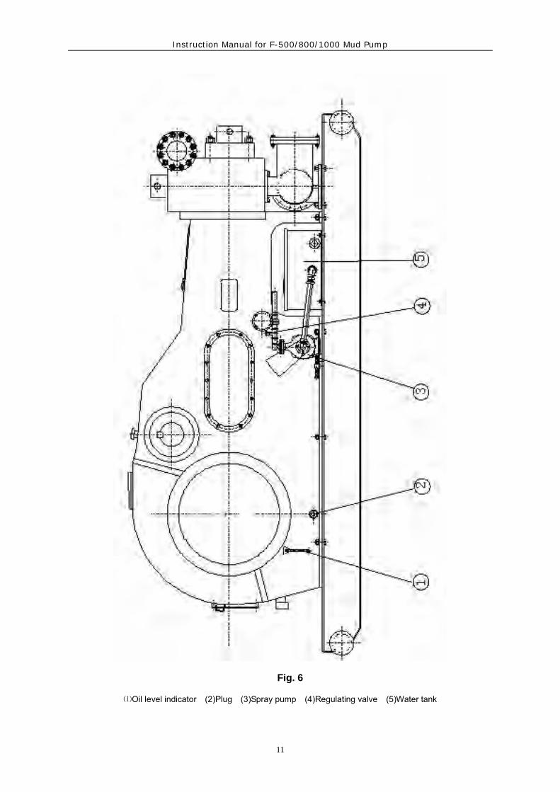
Cooling fluid be transfused from pump (Item 3 Fig .6) and Water tank (Item 5. Fig. 6) to the manifold on the frame. Adjust regulating valve (Item 4 Fig .6) to apply as much water as possible to the liners without splashing back on the crosshead extension rods and diaphragm stuffing box plate. 40L (10-gallons) per minute per liner is the preferred flow rate. If water is allowed to splash on the crosshead extension rods, some of the water will work back into the power end to contaminate the lubrication oil.
21
4 3
Instruction Manual for F-500/800/1000 Mud Pump
11
Fig. 6
⑴Oil level indicator (2)Plug (3)Spray pump (4)Regulating valve (5)Water tank
Instruction Manual for F-500/800/1000 Mud Pump
12
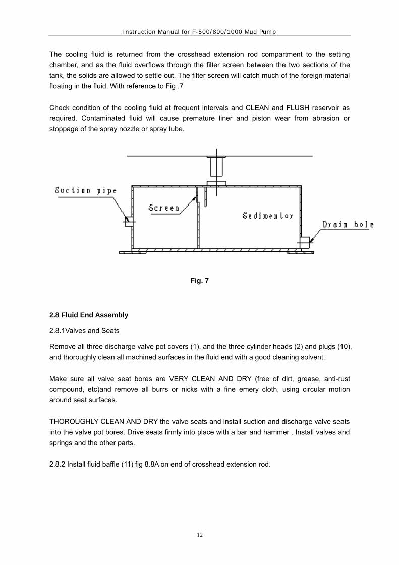
The cooling fluid is returned from the crosshead extension rod compartment to the setting chamber, and as the fluid overflows through the filter screen between the two sections of the tank, the solids are allowed to settle out. The filter screen will catch much of the foreign material floating in the fluid. With reference to Fig .7 Check condition of the cooling fluid at frequent intervals and CLEAN and FLUSH reservoir as required. Contaminated fluid will cause premature liner and piston wear from abrasion or stoppage of the spray nozzle or spray tube.
Fig. 7
2.8 Fluid End Assembly
2.8.1Valves and Seats
Remove all three discharge valve pot covers (1), and the three cylinder heads (2) and plugs (10), and thoroughly clean all machined surfaces in the fluid end with a good cleaning solvent. Make sure all valve seat bores are VERY CLEAN AND DRY (free of dirt, grease, anti-rust compound, etc)and remove all burrs or nicks with a fine emery cloth, using circular motion around seat surfaces. THOROUGHLY CLEAN AND DRY the valve seats and install suction and discharge valve seats into the valve pot bores. Drive seats firmly into place with a bar and hammer . Install valves and springs and the other parts. 2.8.2 Install fluid baffle (11) fig 8.8A on end of crosshead extension rod.

Instruction Manual for F-500/800/1000 Mud Pump
13
F-500, F-800, F-1000 ASSEMBLY OF FLUID END PARTS

Instruction Manual for F-500/800/1000 Mud Pump
14
A cross-section through the fluid end for F-500, F-800, and F-1000 is shown in Fig,8. With reference to Fig 8, clean and assemble the fluid end parts in the following manner: Liners Inspect liner bore again to make sure it is clean and free of foreign particles to assure metal contact between the liner and fluid end. Foreign particles can cause the liner to make up in a “cocked” position resulting in premature wear on liners and pistons. Apply a light coat of grease or oil to the liner bore of the fluid end. A heavy coat of grease will cause a hydrostatic lock which will prevent the liner from seating in its proper position. Push liner through liner bore until it seats metal to metal against the fluid end shoulder. 2.8.3 Piston Rod Clean piston and piston rod, making sure they are free of nicks and burrs. Install “O” ring seal (20) in grove in piston head. Slide piston head on rod while observing that “O” ring does not fall out of groove. Tighten piston rod nut(21) to the following torque.
F-500 500 N.m (368 ft.1bs) F-800/1000 1625-2165 N.m (1200-1600ft.1bs)
Coat liner I.D. and piston O.D. with grease. Check ends of piston rod and extension rod to be sure they are clean and free of burrs. Insert piston rod through liner holding piston rod centered at the rear of the liner. Drive the piston into the liner with a driving tool or a piece of hardwood and sledge hammer. Use caution as the piston rod approaches the crosshead extension rod that the dowel on the end of the piston rod is not damaged. The piston rod must be supported and the dowel guided into the pilot bore. 2.8.4 Piston Rod Clamps The piston rod clamps are machined as one piece and then cut in half, the two pieces are stenciled with matching numbers on each half and have a chain link connecting them together. The two pieces with the same matching numbers should always be kept together as a set. Tighten cap screws to the following torque values. F-500 135 N.m (100 ft.1bs) F-800 135 N.m (100 ft.1bs) F-1000 215 N.m (160ft.1bs) When rods and rod clamps are new a gap in excess of 5.5 mm could be present between the two halves of the clamp. This is satisfactory provided the faces of the rods are seating metal to metal. As wear occurs, the halves will pull closer together. Clamping action will be lost when a gap no longer exist. At this time clamps must be replaced. 2.8.5 Liner Cage and Lower Valve Guide

Instruction Manual for F-500/800/1000 Mud Pump
15
Install rear liner seal (5) and push into position against liner shoulder. Ref. Fig.8. Slide liner cage (6) into fluid end, align one hole in the cage with lower valve pot bore. Set lower valve guide(8) over valve stem through lower hole in cage with the wings on the guide turned crosswise to the pump. Press down on the guide, compressing the valve spring(7) until the guide can be rotated 1/4 turn and seat into place underneath the cage. Insert the lower valve guide locking clip(9) through the pad eyes on the lower valve guide and rotate clip to the right to lock the valve guide tight against the OD of the liner cage. It may sometimes be necessary to put more of less bend in the center of the clip to make it retain the guide tightly while the clip handle snaps into position on the right hand side. 2.8.6 Cylinder Head Insert the outer seal (5) in the fluid end bore against the liner cage. Slide the cylinder head plug(10) into fluid end. Apply a liberal coat of grease to both mating thread surfaces of the cylinder head(2) Screw cylinder head in and tighten with wrench furnished with pump and sledge hammer. Fluid leakage through the weep hole will indicate a defective seal or loose cylinder head. DO NOT plug weep holes as this can result in severe damage to cylinder head threads, thread rings, etc, in event of a liner seal failure. 2.8.7 Discharge Valve Pot Covers Install discharge valve pot gasket(3) into bore, and after liberal application of grease or tool joint compound to the gasket and thread area, tighten the discharge valve pot covers into place, using a sledge hammer and bar. 2.8.8 Discharge Manifold all Models A flange(4” for F-500, 5” for F-800/1000) connection is provided on the discharge manifold. Remove flange and protect gasket area before welding (customer’ option) to the discharge piping. Tighten discharge flange connection bolts to 1625-2165 N.m (1200-1600ft.1bs.) torque. To insure uniform make-up of the ring joint connection, tighten flange bolt nuts in a cross-cross order. If a blind flange is installed on the opposite end of the discharge manifold, check flange bolts and tighten to same specification as noted above. 2.8.9 Suction Flange The suction flange has a standard thread connection (8”NPT for F-500, 10”NPT for F-800,12”NPT for F-1000) and is custom made to match the companion flange on the pump suction manifold. The connection is sealed off by an O-ring seal. Note: Thoroughly clean O-ring groove and face of flanges before making up connection.
Instruction Manual for F-500/800/1000 Mud Pump
16
Tighten flange bolts to 490~665 N.m. 2.9 Accessory Manifold
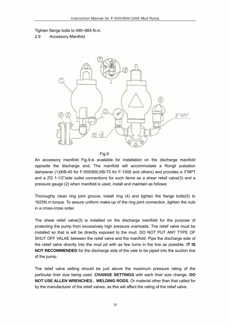
Fig.9 An accessory manifold Fig.9.is available for installation on the discharge manifold opposite the discharge end, The manifold will accommodate a Rongli pulsation dampener (1)(KB-45 for F-500/800,KB-75 for F-1000 and others) and provides a 3”NPT and a ZG 1-1/2”side outlet connections for such items as a shear relief valve(3) and a pressure gauge (2) when manifold is used, install and maintain as follows: Thoroughly clean ring joint groove, install ring (4) and tighten the flange bolts(5) to 1625N.m.torque. To assure uniform make-up of the ring joint connection ,tighten the nuts in a cross-cross order. The shear relief valve(3) is installed on the discharge manifold for the purpose of protecting the pump from excessively high pressure overloads. The relief valve must be installed so that is will be directly exposed to the mud. DO NOT PUT ANY TYPE OF SHUT OFF VALAE between the relief valve and the manifold. Pipe the discharge side of the relief valve directly into the mud pit with as few turns in the line as possible. IT IS
NOT RECOMMENDED for the discharge side of the vale to be piped into the suction line of the pump. The relief valve setting should be just above the maximum pressure rating of the particular liner size being used. CHANGE SETTINGS with each liner size change. DO
NOT USE ALLEN WRENCHES,WELDING RODS. Or material other than that called for by the manufacturer of the relief valves, as this will affect the rating of the relief valve.

Instruction Manual for F-500/800/1000 Mud Pump
17
The mounting for KB-75 and KB-45 pulsation dampener(1) is a flange with R-39 ring gasket. Before installing dampener, thoroughly clean ring groove and ring, and after setting dampener into place, tighten the nut(8) to 1020 N.m torque. To insure uniform make-up, tighten nuts in a cross-cross order. Precharge dampener before starting up pump. Precharge pressure should not be more than 2/3 of the pump discharge pressure, or a maximum of 4.5Mpa. CAUTION: Use only compressed nitrogen or air. Do not charge with oxygen.
3.LUBRICATION
Proper lubrication of the moving parts in any piece of machinery is the most important single factor affecting its ultimate life. To obtain maximum trouble-free service life from the power end of the AH pump, it is necessary to perform routine maintenance care and inspections to insure the proper amount of CLEAN lubricant is being provided. The F-Series pumps utilize the controlled flow oil bath splash and pressure system to lubricate the entire power end. The type of pressure system provided in each individual pump will govern the minimum SPM at which the pump can be operated, i.e. pumps which have pressure lubrication only to the main and pinion bearings, have a minimum rated speed of 40 SPM. Pumps in which pressure lubrication is provided to the main, pinion, and crosshead bearings and crosshead compartments may be operated at a minimum speed of 25 SPM. Provided there is a minimum of 0.035Mpa(5PSI) oil pressure. F-series pump have the total pressure lubrication system, and which can be operated at 25 SPM (at pressure of 0.035Mpa) CAUTION: The pressure lubricating can be provided with an externally mounted oil pump driven through V-belts or internally mounted oil pump driven from the main gear. When an internally mounted oil pump is used, the direction of rotation of the pinion shaft must be as shown in Fig.10

Instruction Manual for F-500/800/1000 Mud Pump
18
Fig.10
3.2 Controlled Flow Splash System
The controlled flow splash lubrication system is the same for all F-Series pumps, regardless of the type of oil pump drive provided for the pressure system In the controlled flow splash system, the main gear picks oil up from the reservoir, and when the teeth mesh with the pinion, the oil is displaced into various troughs and compartments in the frame. With reference to Figure 15, the oil thrown into oil trough (7) is directed through the oil tube (8) to the two pinion bearings. Oil passage from the of the crosshead guide compartment to the crosshead bearing is shown in Figure 11, Oil accumulates in the compartment over the crossheads. The oil runs through the nipple(1) into the crosshead retainer to the oil passages (5) and on to the crosshead pin bearing. As noted, the duplicate set of passageways (5) in the crosshead pin permits the crosshead pins to be rotated without having to give attention to hole alignment. This permits the installation of crosshead pins from either direction.

Instruction Manual for F-500/800/1000 Mud Pump
19
For F-500 pump. Oil passage from the top of the crosshead guide compartment to the crosshead bearing is shown in Fig. 11A. Oil accumulates in the compartment over the crossheads. The oil runs through the oil passage, (1) (2) and crosshead pins oil passage (3) ,and on to the crosshead pin bearing. As noted, the duplicate set of passageways (3) in the crosshead pin permits the crosshead pins to be rotated without having to give attention to hole alignment. This permits the installation of crosshead pins from either direction.
Fig. 11
(1) Nipple (2) retainer (3) bolt (4) crosshead pin (5) oil passage
3.3 Total Pressure Lubrication System
The total pressure lubrication system, incorporating the oil pump for the F-series pumps, is shown in Figure 12. In this system, filtered oil is supplied to the pump through the suction filter (1) and is discharged from the pump into the manifold block (2). Oil is distributed from the manifold

Instruction Manual for F-500/800/1000 Mud Pump
20
block to the pinion shaft bearing oil line (3) and spray nozzle (3A), and to the main bearing oil line (4) and the crosshead compartment manifold block (4A) located above the crosshead compartment. The crosshead compartment manifold block (4A) distributes oil to the crosshead, crosshead bearings, and extension rods. A pressure gauge (5) is mounted to the back wall of the frame to show oil pressure being maintained in the manifold block. The oil pressure will, of course, very with the speed of the main pump, however if a sudden pressure drop or increase occurs, refer to the section on maintenance of lubrication system for possible cause. A pressure relief valve (6) is mounted to the manifold block (2) to keep excess pressure from damaging oil pump and drive. The relief valve is preset at 0.27 Mpa (40 PSI) and must not be tampered wit. When installing the internally mounted oil pump(9 Fig.12), position pump so that the back face of the drive gear is flush and parallel with the edge of the main gear, and gear teeth have 0.60~0.90mm backlash.

Instruction Manual for F-500/800/1000 Mud Pump
21
Fig. 12
(1) Filter (2) manifold block (3) oil line (3A) spray nozzle
(4) main bearing oil line (4A) Manifold block (5) pressure gauge (6) relief valve (7) oil
trough (8)oil tube (9) Lubrication pump
3A
7
8
4A
6
2419
3A3
5 4

Instruction Manual for F-500/800/1000 Mud Pump
22
A typical layout for the pinion shaft driven oil pump is shown in Fig. 13.The oil pump (1) is
piped into the oil system through the suction and pressure connections on the bottom
inside wall of the power frame.
Fig. 13
(1) Oil pump (2) V-belt (3) guard
Ref. Fig.13. Adjust the V-belt drive (2) to a point where the two halves of the belt can almost be “pinched” together between the thumb and fingers at the center of the drive. Over tightening can cause premature failure of the pump. To prevent possible injury, always install guard (3 Fig.13) over V-belts before putting pump into service.
3.4 Maintenance of The Lubrication
Adequate lubrication of the moving parts is, as stated, the most important single factor affecting the ultimate service life of the pump, CARE AND MAINTENANCE of the system is the sole responsibility of the operator or crew to which it has been assigned, and the extent to which this is applied will determine the amount of trouble – free service life that will be obtained. The lubricant recommendations shown below, on the name plate on the side of the pump, are the result of extensive field tests. Substitutions should be made only in extreme emergencies.
Lubrication specifications:
Use Extreme Pressure (EP) non-corrosive, anti- foaming gear lubricant as follows: Temperatures +30° F~ +155° F (-1°C~ +68°C) AGMA 6# EP Temperatures + 0° F~ + 80° F (-18°C~ +27°C) AGMA 4# EP Temperatures -20° F~ + 40° F (-29°C~ + 4°C) AGMA 1# EP
3
2
1

Instruction Manual for F-500/800/1000 Mud Pump
23
Oil reservoir capacity F-500 246 liters (65 US.Gal) F-800 246 liters (65 US.Gal) F-1000 284 liters (75 US.Gal) ONCE EACH TOUR, check and maintain oil level at the FULL mark on the bayonet gauge. PUMP MUST BE SHUT DOWN and allowed to stand idle for approximately five minutes to allow oil level to equalize. ONCE EACH SIX MONTHS, or more often if oil becomes contaminated with abrasive particles or corrosive compounds, drain and flush the oil reservoir new lubricant. Oil drains are located on either side of the pump frame. During the flushing procedure, thoroughly clean the oil troughs and the compartment in top of the crosshead guide. Also clean or replace the filter element in the air breather cap and clean suction screen. Remove covers from settling chamber and purge out contaminants before adding new oil. Routine inspection on condition of oil should be made as condensation of moisture in the air, intrusion of mud, water or dirt, can necessitate a more frequent oil change. A settling chamber is located in the forward area of the power end floor, Contamination in the oil splashed into this area is allowed to settle out and should be drained out of the pump through the clean out covers located on the frame wall underneath the crosshead inspection doors. Once each month, remove clean out covers on both sides of pump to drain contaminated oil from setting chamber. Approximately 15-gallons of oil be lost; replenish the main reservoir to compensate for the amount drained out. Once each week, remove one of the lower 1/2” capscrews that secure the clean out cover to the frame to drain off water condensate. ONCE EACH TOUR, check oil level in main reservoir. Maintain at full mark on dipstick to the manifold block. If loss of pressure occurs, check for:
Clogged suction screen Low oil level Slipping V-belt drive Broken or loose connections Damaged or worn oil pump Defective Relief valve For an abnormal increase in oil pressure, check for:

Instruction Manual for F-500/800/1000 Mud Pump
24
Plugged oil lines Contamination causing oil to be viscous Relief valve inoperative Defective pressure gauge Other conditions
4. Maintenance
4.1 Power End
Routine inspection of the power end is the most important form of preventive maintenance and will result in considerable savings by detecting any major trouble that might be developing and allowing the necessary repairs to be made on a planned or transport rig-down time.
4.1.1 Check tightness of the main bearing bolts. Bolts must be tightened to the following torque:
F-500 4065 N.m (3000ft.lbs)
F-800 8620 N.m (6360ft.1bs)
F-1000 11920 N.m (8800ft.1bs)
4.1.2 Safety wires
Check safety wires on all bolts including the main bearing hold-down bolts and eccentric bearing retainer bolts. Replace any broken wires after retightening the bolts. Refer to crankshaft assembly section for bolt requirements.
4.1.3 Oil lines
Check all oil lines to insure they are intact and free of obstructions. Check oil pump suction hose for damage or flat areas.
4.1.4 Suction filter
Check condition of suction filter. Clean and replace as required.
4.1.5 Main bearing cover
Remove the main bearing cover and check tightness of main bearing retainer blots, condition of the bearing rollers, etc. Clean and remove any sludge or foreign substance that might have accumulated at the bottom of the bearing area.
4.1.6 Main gear and pinion teeth
Inspect the condition of the main gear teeth and pinion gear teeth for any indications of abnormal wear. During the initial break-in period there will be some pitting on the face of the gear teeth. This is referred to as“ initial pitting ”and is not harmful to the life of the

Instruction Manual for F-500/800/1000 Mud Pump
25
gear. However, if routine inspection indicates the degree of pitting continues to increase, immediately contact the pump manufacturer for a more thorough inspection of the gear.
4.1.7 Crosshead pin bolts and crosshead guides
Remove cover and check condition of the crosshead pin bolts and safety wires. (Center crosshead pin bolts can be reached by removing back cover and placing eccentric on outer top dead center). Tighten crosshead bolts (Item 4 Fig .18) to the following torque:
F-500 120-135 N.m (90-100ft.lbs) F-800 190-205 N.m (140-150ft.1bs) F-1000 225-240 N.m (165-175ft.1bs)
DO NOT EXCEED THESE VALUES. USE TORQUE WRENCH
If the crosshead or guide shows abnormal wear or scoring, replace immediately as the metal particles can cause damage to the bearings, etc; Excess wear can also cause rapid wear to the piston and liner.
4.1.8 Oil and oil reservoir
Check condition of the oil and cleanliness of the oil reservoir. Service oil system as described in the Lubrication Section of this manual.
4.2 Roller Bearings
Although the basic construction of the various sizes of F-series pumps varies somewhat, they all have one very important detail in common roller bearings. A roller bearing is a precisely built machine within itself; therefore, careful handling is required in order to obtain the long service life and high load carrying characteristiAH associated with anti-frication bearings. The main bearings are self-aligning spherical roller bearings. The pinion shaft is mounted on straight roller bearings. The eccentric bearings are straight roller with thrust plates on each side to keep the eccentric straps in line, and the crosshead pin bearings are straight needle roller bearings. None of the bearings require special adjustments. All inner and outer races are assembled by means of very accurate fits. This accuracy is necessary; therefore, if the bearings are to be used again, the inner and outer races and the roller assemblies of each bearing must be kept together, and reinstalled exactly as they came off. It is always necessary to completely replace any roller bearing that fails, even though only one part of the bearing shows damage. Since the running clearances of these bearings are extremely small, excessive clearances, worn or grooved raceways, and any

Instruction Manual for F-500/800/1000 Mud Pump
26
pitting or flaking of the parts is indication of failure and the entire bearing should be changed as soon as possible. All roller bearings are assembled to their shafts by means of shrink fits. (Ref. bearing fit data under each shaft assembly.) Damaged or worn bearings and raceways can be removed by driving them off the shaft with a bar and hammer. They also can be cut off from the shaft with a burning torch, but care must be taken not to burn into the shaft. Bearings should always be heated in an oil bath, the temperature of which should not exceed 149℃ .(300°F). Be certain that both the oil and the container are very clean. If the oil container is in direct contact with the fire, place a rack into the container so that the bearings will not rest on the bottom. Do not leave the bearings in the oil bath longer than three minutes. Do not heat the bearings with a torch unless it is the only possible means available. When it is necessary to use a torch, it should be used only by an experienced welder or mechanic. Hold the torch at least 150mm (6 inches ) away from the bearing and keep the torch moving at all times. Heat the bearing only until it is hot to the touch. Use a Tempil stick. DO NOT OVERHEAT THE BEARING. Overheating draws the temper of the metal and soften bearing. Once the heated bearing is in place on the shaft, hold it in place until it cools. NEVER
USE WATER OR ANY OTHER LIQUID TO COOL A HOT BEARING. Rapid cooling will cause the surfaces of the races and rollers to “check” or crack and the bearing will fail immediately. Never strike a roller bearing with a steel hammer. If the bearing must be driven into position, use wood or a soft hammer and strike lightly. Always coat the shaft or housing with grease before installing the bearing. Clean white lead, that is an anti-seize compound, is the best lubricant for this purpose. Do not remove a new bearing from the box or wrapping until it is to be installed. Protect it from dirt and other foreign matter at all times. If a bearing must be cleaned, use clean kerosene or other solvent.
4.3 Pinion Shaft Assembly

Instruction Manual for F-500/800/1000 Mud Pump
27
Fig.14
GHART 1
mm
Description position F-500 F-800 F-1000
Inner Race to Shaft A T0.030~T0.081 T0.035~T0.085 T0.050~T0.109
Outer Race to Bore B L0.068~T0.018 L0.095~L0.010 L0.0105~L0.015
Carrier to frame Bore C L0.203~L0.076 L0.203~L0.076 L0.203~L0.076
Inches
Description Position F-500 F-800 F-1000
Inner Race to Shaft A T0.0012
~T0.0032
T0.0014
~T0.0033
T0.002
~T0.0041
Outer Race to Bore B L0.0015
~T0.0005
L0.0037
~L0.0004
L0.0041
~L0.0006
Carrier to frame Bore C L0.008
~L0.003
L0.008
~L0.003
L0.008
~L0.003
The pinion is an integral part of the shaft leaving only the installation of the bearings and oil seal Spacer to complete the assembly.

Instruction Manual for F-500/800/1000 Mud Pump
28
The running clearances of the bearings are predetermined by their precision fit to the shaft and the bearing carrier. When performing maintenance or overhaul, make sure the fits show in chart I are obtained.
When installing the pinion shaft assembly in the pump observe the following precautions:
a. Insure pinion bearing carrier gasket(1) and oil seal carrier gasket(2) are in place and in good condition.
b. When installing the pinion bearing carrier(3) and the oil seal carrier MAKE SURE THE CARRIERS ARE INSTALLED WITH DRAIN HOLES AT THE TOP to correctly position oil troughs and align drain holes.
c. Remove burrs, dents or gouges from the OD of the oil seal spacer(5) before sliding oil seal carrier(4) into place. Exercise care when sliding lip of seal over end of shaft to prevent it from being damaged by the sharp edge of the keyway. Also pay particular attention to insure oil seal lip IS NOT TURNED UNDER by edge of spacer when sliding seal onto the spacer.
d. Tighten pinion bearing carrier bolts (6) to the approximate torque shown below.
F-500 135~170N.m (100-125ft·lbs)
F-800 135~170N.m (100-125ft·lbs)
F-1000 190~225N.m (140-165ft·lbs)
e. Check condition of the pinion bearing inner and outer race and rollers. If there is any indication of galling, flaking or grooving, or if diametral clearance exceeds 0.20 ~ 0.25mm, it is recommended the entire bearing be replaced.
4.4 Crankshaft Assembly( Fig.15)
The crankshaft assembly consists of the crankshaft, eccentric ring gear, eccentric strap with bearings, and the main bearings.
The running clearances of the bearings are predetermined by their precision fit to the

Instruction Manual for F-500/800/1000 Mud Pump
29
shaft and their respective bores, when performing any maintenance or overhaul, make sure the fit. shown in chart II are obtained.
Fig.15
CHART II
mm
Description position F-500 F-800 F-1000
Instruction Manual for F-500/800/1000 Mud Pump
30
Inner Race to Shaft A T0.050
~T0.109
T0.055
~T0.114
T0.060
~T0.121
Outer Race to Bore B L0.080~0 L0.090~ 0 L0.095~0
Inner Race to Shaft C T0.076
~T0.172
T0.127
~T0.228
T0.127
~T0.228
Outer Race to Bore D T0.100~0 T0.100~0 T0.100
~L0.025
Gear to Flange E T0.025
~T0.127
T0.025
~T0.127
T0.025
~T0.127
Carrier to Frame Bore F L0.050
~T0.025
L0.051
~T0.051
L0.051
~T0.051
Outer Race to Bore G 0
~T0.050 T0.025
~T0.085 T0.012
~T0.079
Inner Race to Pin H 0
~T0.045 T0.025
~T0.075 T0.025
~T0.075
Inches
Description position F-500 F-800 F-1000
Inner Race to Shaft A T0.0020
~T0.0043
T0.0022
~T0.0045
T0.0024
~T0.0048
Outer Race to Bore B L0.0031~0 L0.0035~ 0 L0.0037~0
Inner Race to Shaft C T0.0030
~T0.0068
T0.005
~T0.0090
T0.005
~T0.009
Outer Race to Bore D T0.0039~0 T0.0039~0 T0.0039
~L0.0010
Gear to Flange E T0.001
~T0.005
T0.001
~T0.005
T0.001
~T0.005
Carrier to Frame Bore F L0.0020
~T0.001
L0.002
~T0.002
L0.002
~T0.002
Outer Race to Bore G 0
~T0.002
T0.0010
~T0.0034
T0.0005
~T0.0031
Inner Race to Pin H 0
~T0.0018
T0.0010
~T0.0030
T0.001
~T0.0030
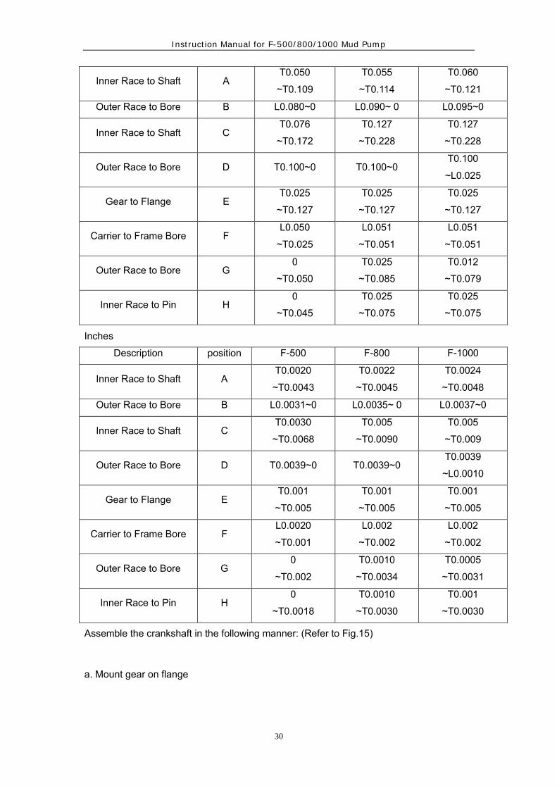
Assemble the crankshaft in the following manner: (Refer to Fig.15)
a. Mount gear on flange

Instruction Manual for F-500/800/1000 Mud Pump
31
Thoroughly clean mating faces of ting gear and flange and bolt flange into position. Tighten flange bolts(2) to the following torque:
F-500 400N.m (295ft·lbs)
F-800 1055N.m (778ft·lbs)
F-1000 1055N.m (778ft·lbs)
Set crankshaft on a set of rollers( at main bearing position) and check runout on face of gear with a dial indicator. If total indicator runout exceeds 0.15mm, remove gear and gear and determine cause of misalignment.
NOTE: If runout on face of gear is checked while crankshaft is mounted in the pump frame, the running clearance in main bearings will require that a simultaneous set of dial indicator readings be taken at the end of the shaft and the face of the gear; the actual face runout at any point being the difference between these readings.
b. Install the outer races of the eccentric bearings(13) and the outer race retainer ring(3) in the three eccentric straps. Outer race retainer ring must be positioned so that oil scoop is at the bottom when pump is at mid-stroke. Tighten retainer bolts(4) to the following torque: safety wire heads.
F-500 60~90N.m (40~66ft·lbs)
F-800 60~90N.m (40~66ft·lbs)
F-1000 60~90N.m (40~66ft·lbs)
NOTE: The inner and outer races of the eccentric bearings are matched and must not be intermixed.
c. Install the outer race of the crosshead bearings (19) in the three eccentric straps. It is preferred that the outer race assembly be “passed” into position of frozen in “dry ice” or a deep freeze until it can be inserted into the bore. Under emergency circumstances, the outer race assembly can be installed by using a large torch and hearing the eye of the eccentric strap. DO NOT EXCEED 149℃ (300℉) (Use Tempil-Stik) and DO NOT USE WATER to cool the strap.
NOTE: The inner and outer races of the crosshead bearings are matched and should not be intermixed.

Instruction Manual for F-500/800/1000 Mud Pump
32
d. Install the inner race of the crosshead bearing on the crosshead pin and mark according to their respective eccentric strap positions. Remove all nicks and burrs before shrinking race into place. Refer to bearing fit Position H Chart II.
e. Install inner race of the center eccentric bearing on the shaft, slide center strap into position and install inner race clamp(5). Tighten socket head screws(8A) in clamp to the following torque.
F-500 24~36N.m (18~26ft·lbs)
F-800 60~90N.m (44~66ft·lbs)
F-1000 60~90N.m (44~66ft·lbs)
f. Install snap ring (7) in the groove on RH eccentric and shrink inner race of eccentric bearing on shaft. After sliding the RH eccentric strap into position, install inner bearing retainer (14).
Tighten inner race retainer bolts(8) to the following torque
F-500 60~90N.m (44~66ft·lbs)
F-800 60~90N.m (44~66ft·lbs)
F-1000 60~90N.m (44~66ft·lbs)
g. Install the LH eccentric bearing ( other than for snap ring) and eccentric strap under the same procedure outlined in step( f) above.
h. Place main bearings (9) in the main bearing carries (10 RH and 11LH) and install outer race retainer (12) and retainer bolts (15). Tighten bolts to the following torque:
F-500 24~36N.m (18~26ft·lbs)
F-800 60~90N.m (44~66ft·lbs)
F-1000 60~90N.m (44~66ft·lbs)
NOTE: Even though the main bearing carriers (10 RH and 11LH) have different configurations on the OD, they are interchangeable and will fit into the pump frame on either side. The purpose of the shoulders on the OD of one of the carriers is to locate and retain the crankshaft in its respective position in the

Instruction Manual for F-500/800/1000 Mud Pump
33
frame.
i. After installing the two main bearing spacers (16), shrink main bearings (9) on each end of the shaft. Install inner race retainers(17) and retainer bolts(18). Tighten retainer bolts to the following torque:
F-500 24~36N.m (18~26ft·lbs)
F-800 60~90N.m (44~66ft·lbs)
F-1000 60~90N.m (44~66ft·lbs)
4.5 Installing Crankshaft Assembly In Frame
In order to obtain a more precise fit between the main bearing housing and the frame bore on BS F-Series pumps, the installation procedures outlined below are to be followed (Refer to Fig.16)
Fig.16
4.5.1 Place piece of wood between eye of eccentric strap and crosshead guide( as shown in Fig.17、17A) to protect guide from scoring or gouging as the straps are sliding into position.
4.5.2 Rotate the main bearing carrier so that two flat spots(180° apart) are parallel with the main bearing bolt holes, and slowly lower the crankshaft into position.(The flat spot provides clearance for the main bearing bolts.)

Instruction Manual for F-500/800/1000 Mud Pump
34
4.5.3 After placing crankshaft in the frame, and before installing the main bearing caps, check the rollers in the main bearings to assure that each row of rollers in each bearing is equally loaded. Equal loading is obtained by positioning the floating bearing carrier so that the same number of inner and outer rollers supporting the weight of the crankshaft in each bearing are tight. Because of tolerances, etc., the total number of tight rollers could very slightly between individual bearings.
4.5.4 Install and shim main bearing caps to obtain0.10mm(0.004″) clamp or preload on
the main bearing carrier is obtained by placing the correct amount of shims under the main bearing cap. The required amount of shims is determined as follows: Fig.16
a. Install 0.50mm (0.02″) shims under both ends of the main bearing cap. b. Place a piece of lead wire(approximately 0.8mm diameter) or Plastigage between
OD of bearing carrier and ID of bearing cap, as near center of bearing cap as can be determined , and tighten main bearing cap bolts to torque values shown in Chart III.
c. Remove main bearing cap and determine clearance between bore of cap and OD of
bearing carrier by either mikeing thickness of lead of measuring compressed dimension of plastigege.
d. Using this dimension, calculate the required thickness of shims as follows:
Subtract thickness of compressed lead or Plastigage form the original 0.50mm shim thickness. Then subtract 0.1mm for preload. The result is the correct shim thickness required.
Example: 0.50mm Original shims 0.002″ Less 0.13mm Lead Thickness Less 0.005″ 0.37mm 0.015″ Less 0.10mm Clamp Fit Less 0.004″ 0.37mm Correct Shim Thickness 0.015″ NOTE: Machining tolerances make it necessary to determine individual shim
requirements for each (right hand and left hand) main bearing cap. e. Install main bearing caps with the correct amount of shims as determined above, and
tighten main bearing bolts to torque values shown in chart III. f. Again check inner and outer row of rollers on each bearing as previously outlined to
assure equal loading is still present on each bearing. CHART III
Torque Thread Size
Wrench Size
N.m ft. lbs mm in

Instruction Manual for F-500/800/1000 Mud Pump
35
F-500 4065 3000 1 3/4″- 8UN 55 F-800 8620 6360 2 1/4″- 8UN 76.2 3″ F-1000 11920 8800 2 1/2″- 8UN 82.5 3 1/4″
4.6 Installation Of Crosshead Guides For AHF-800/1000
When installing crosshead guides observe the following procedures and precautions: 4.6.1 Thoroughly clean all dirt or contamination and remove all burrs or tough edges
from both sides of the guides and the frame bore where the guides fit. 4.6.2 If old guides are to be reused, inspect the wearing surfaces for wear and scoring
streaks.
NOTE: For F-800, F-1000, upper and lower crosshead guides are NOT interchangeable. In these pumps, the guide are machined so that the lower guide places the crosshead on frame centerline, and upper guides are machined to afford proper crosshead to guide clearance.
4.6.3 Install upper and lower guides, Torque guide screws to 200~270 N.m
(150~200ft·lbs). 4.6.4 Check between frame and guides at points A, Fig.18, with 0.05mm(0.002″) feeler
gauge to make sure gauge to make sure guides fit into bore. 4.7 Installing Crosshead Guide For F-500
When crosshead guides become worn or damaged, they should be replaced, observing the following precautions. (Note: The crankshaft must be pulled to allow clearance for removal and installation of the guides.)

Instruction Manual for F-500/800/1000 Mud Pump
36
Fig.16B
4.7.1 Remove worn or damaged guides. 4.7.2 Thoroughly clean the frame bore and the mating surfaces of the frame wall and
crosshead guide (Position A) These surfaces MUST BE ABSOLUTELY FREE OF DIRT OR FOREIGN MATERIAL in order for crosshead guide to give proper alignment between the power end fluid end parts.
4.7.3 Slide O-ring seal (1) over end of crosshead guide. Coat with light oil or anti-seize
compound, and position guide into frame bore. Use caution to prevent damage to the O-ring seal. The crosshead guide is symmetrical and can be rotated top to bottom. The fit between OD of crosshead guide and frame bore (Position B ) is shown below: L 0.102mm—L 0.203mm ( L 0.004″--L 0.008″)
4.7.4 Install crosshead guide retainer bolts (2) and tighten crosshead guide into place.
Tighten bolts to the torque shown below: 675~1012 N.m (500~750ft·lbs).
For more uniform make-up, tighten bolts in a cross-cross procedure. 4.7.5 Check mating surfaces (position A ) for metal-to-metal make-up by Attempting to
insert a 0.025mm-0.050mm feeler gauge between the two parts. 4.7.6 Install the two oil lines( 3 and 4). NOTE: The crosshead guides are symmetrical and can be rotated from top to bottom. In

Instruction Manual for F-500/800/1000 Mud Pump
37
emergencies where bottom surface of guide becomes damaged and time does not permit a new part to be obtained, the damaged guide can be rotated 180°to allow the crosshead to run on a new surface. It will be necessary to pull crankshaft for clearance to rotate the guide. The damaged can then be replaced at a more convenient time. 4.8 Installation Of Crossheads
The crossheads in the pumps can be installed through the front (fluid end) or back end of the crosshead guide. Reference Fig.18.18A. When installing crossheads, observe the following precautions:
Fig.17 Fig.17A
4.8.1 Thorughly clean all dirt or contamination and remove all burrs or rough edges from OD of the crosshead, crosshead pin bores, and inner bore of crosshead guide. Dry crosshead pin bore so taper bore connection will make metal to metal See Note.
4.8.2 Position “ eye” of eccentric at the opening in the side of the crosshead guide.
Block eccentric strap so that crosshead will clear the “eye” as it is sliding into position to where the crosshead pin holes are in alignment. Fig 17. 17A
4.8.3 Install the left hand crosshead first, Rotate eccentric assembly to move ”eye” into
center crosshead and right hand eccentric strap “eye” back, affording clearance to install center pin through right hand crosshead inspection door. Remove diaphragm stuffing box plate (1, Fig.18) and install right hand crosshead through this bore. Slide into place and install crosshead pin.
4.8.4 Install crosshead pin retainer (2) and retainer bolts (3) and rotate pin until the four
crosshead retainer to crosshead bolt holes (4) are in alignment. Install the crosshead retainer to crosshead bolts and make up hand tight. Ref. Fig 18.18A
Wood BlockWood Block

Instruction Manual for F-500/800/1000 Mud Pump
38
Fig.18 Fig.18A
Referring back to fig.11.11A crosshead pin (4) can be installed without regard to oil holes(5). Two holes are provided so the pin can be rotated 180°in relation to pin to retainer plate screws (3). Seat crosshead pin in tapered bore by bumping large end with a light blow. Tighten retainer bolts(3 and 4, Fig.18) to the following torque and safety wire:
F-500 120~135N.m (90~100ft·lbs) F-800 190~205N.m (140~150ft·lbs) F-1000 225~240N.m (165~175ft·lbs) DO NOT EXCEED THESE VALUES. USE TORQUE WRENCH. NOTE: To pull the crosshead pin, remove the four crosshead retainer to crosshead bolts
(4) and screw two of the bolts into the “jack screw” holes (5). Tighten the two jack screw bolts until the pin breaks loose. Complete removal of crosshead pin retainer plate (2) and slide pin out of bore.
4.8.5 Check running clearance of crosshead by sliding long “feeler” gauges between
top of crosshead guide bore. The clearance should not be less than 0.508mm(0.020″). Check with long feeler gauge over entire surface of crosshead. NOTE: Less running clearance at center of crosshead can be caused by
“swelling” from overtightening the crosshead pin retainer bolts (4). If present, lossen pin and retighten into place by using the make-up torques shown in paragraph 4.
4.8.6 For F-500
Install the center crosshead first. Crosshead pin is installed through the top of the pump by removing the inspection cover. Slide crosshead pin into bore but do not seat taper until the crosshead pin retainer (2) Fig.18A has been installed.

Instruction Manual for F-500/800/1000 Mud Pump
39
NOTE: If old crossheads are to be reused, inspect the sliding surfaces for wear or
scoring. If necessary, the crosshead may be switched to opposite sides of the pump and rotated 180°to provide a smooth surface for the bottom of the crosshead.
The center crosshead can be rotated 180°and the crosshead pin installed from
the opposite side of pump. 4.9 Checking Crosshead Alignment
In order for the pistons to run true in the liners, the crosshead must travel in a straight line along the horizontal centerline of the frame bore. to check and adjust crosshead alignment, proceed as follows:
4.9.1 Remove diaphragm stuffing box from the diaphragm plate, (Fig.18). Do not remove
the plate, 4.9.2 Position crosshead at the extreme front of its stroke. With inside calipers or
telescoping gauges, accurately measure the distance from the diaphragm plate bore to the crosshead extension rod at the top and bottom. Compare the two measurements to determine the position of the rod relative to the centerline of the bore.
4.9.3 Rotate pump to extreme rear of stroke and take measurement again at the same
place. Compare these measurements to the ones taken at the front of the stroke to determine if crosshead is running horizontal.
4.9.4 If the centerline of the extension rod is more than 0.381mm (0.015″) low in the
diaphragm plate bore, shims should be inserted under the lower guide to bring the extension rod back to center, provided there is ample clearance between the top of crosshead and upper crosshead guide. It is normal for the lower guide to wear more at the rear due to heavier loading at this point because of the angle of the eccentric strap. It is permissible to shim the guides on a taper if is done accurately to provide firm support for the guide. Do not shim guides to less than 0.50mm (0.020″) clearance. Large crosshead clearances are acceptable due to characteristiAH of triplex pump operation, the crosshead pressure is always on the lower guide.
4.9.5 Cut shims from steel shim stock long enough to reach completely across the
guides. Cut tabs on the side to bend down over frame supports to hold them in place. Refer to items 3 and 4 under Installation of Crosshead Guides.
4.10 Fluid End Maintenance

Instruction Manual for F-500/800/1000 Mud Pump
40
From many years, the fluid end of a pump was considered a non-wearing part which did not cause any concern other than possible infrequent repairs or replacements resulting from fluid cuts or washout. However, the higher pressures of the present-day drilling requirements have resulted in higher stresses being imposed on the fluid end which, when combined with the corrosive characteristiAH of the drilling fluid, have resulted in the demand that more and better maintenance be given to the fluid end parts and pieces if a reasonable operating life is to be obtained. A few of the obvious points are as follows:
a. Make sure all valves on the discharge side of pump are opened before pump is put
into operation. Kicking pump in against a closed valve can often be the start of a fatigue crack. An open crack may not necessarily occur at the precise moment, however a small crack could occur and start the process of “corrosion fatigue failure”
b. Do not engage pump clutch when prime mover is running at a high rate of speed. To
do can cause undesirable shock loads against both power end and fluid end. c. Properly maintain pressure relief valve to assure it is set for the pressure rating on
the liner size being used. d. Do not operate the pump for an extended period of time if a severe fluid knock is
present. e. Properly prepare fluid end for storage. When pump is to be shut down or not
operated for a period of ten days or more, it is recommended that the fluid end parts such as liners, pistons, rods, etc, be removed from the pump and the fluid end flushed out completely with fresh water, after a thorough flushing, apply grease or a rust preventative to all of the machined surfaces such as valve pot cover threads, valve pot cover gasket surfaces, valve seats, liner bores, etc. the parts removed from the pump including liner, piston rods, etc., should of course be protected from the elements. This will not only extend the life of the fluid end through resistance to corrosion, but will also protect the usable life still left in the expendable parts and maintain them in good condition for installation in the pump at the next start-up period,
Maintenance and repairs should be made on the fluid end assembly by observing the following precautions. Refer to figure 19.19A.19B. The fluid end assembly for these triplex pumps consists of three forged cylinder blocks, complete with valve pot covers and cylinder heads, a suction manifold, and a discharge manifold.
4.10.1 Fluid Cylinder Blocks

Instruction Manual for F-500/800/1000 Mud Pump
41
The three separate fluid cylinder blocks (1) blot metal-to-metal to the power end frame through retainer studs (2), Alignment with the power end frame bores is obtained through the “pilot” boss on fluid end.
However, to obtain accurate alignment, all nicks or burrs must be removed from
“pilot” boss and frame bore and all dirt and foreign matter cleaned from the mating surfaces; otherwise cylinder blocks could make up in a “cocked” or misaligned position.
The fit between “pilot” boss and frame bore (Position A) is as follows: Install the three cylinder block nuts to the torque values shown in Chart
V. 4.10.2 Suction Manifold
The suction manifold (3) bolts to each cylinder block and is sealed through the O-ring in the connection flange. Thoroughly clean O-ring groove, the O-ring sealing surface on bottom of the cylinder block, and replace O-ring seal before bolting manifold into position. The flange connection MUST make up metal-to-metal to retain the O-ring seal, therefore any nicks, grooves or washouts on the sealing surface must be repaired before installation. Ref. Welding and Repair Section in this manual for repair procedures. Start all suction manifold bolts (5) in the three cylinder blocks before tightening. Tighten to torque values shown in Chart V.
4.10.3 Discharge Manifold The discharge manifold bolts to each cylinder block and is sealed through the O-ring
in the connection flange. Thoroughly clean the O-ring groove, the O-ring sealing surface on face of the
cylinder block before bolting the manifold back into position. The flange connection MUST make up metal-to-metal to retain the O-ring seal, therefore any nicks, grooves, or washouts on this sealing surface must be repaired before installation. Ref. Welding and Repair Section in this manual for repair procedures.
Start all discharge manifold bolts (8) in the three cylinder blocks before tightening. Tighten to torque values shown in Chart V. tight cylinder block to power frame stud nuts to torque values shown in Chart V.
4.10.4 Cylinder Head Thread Ring
A replaceable cylinder head thread ring (9) is bolted on to the face of the cylinder
Instruction Manual for F-500/800/1000 Mud Pump
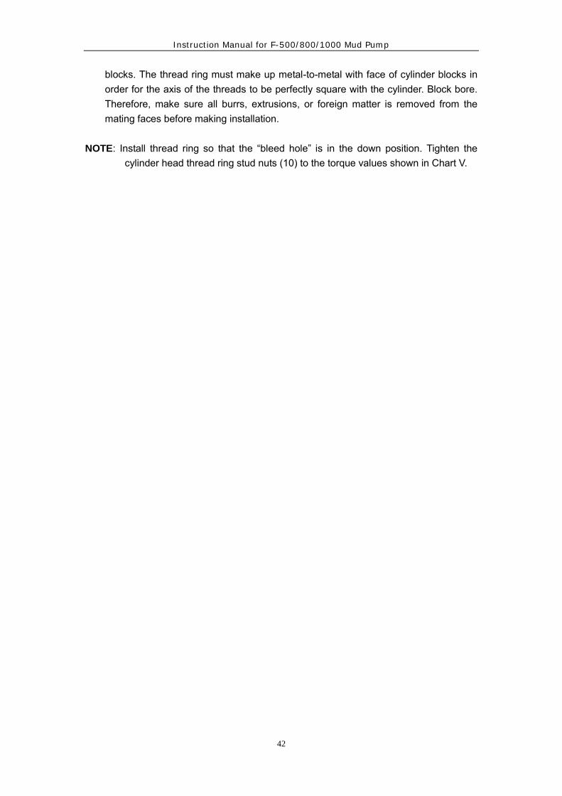
42
blocks. The thread ring must make up metal-to-metal with face of cylinder blocks in order for the axis of the threads to be perfectly square with the cylinder. Block bore. Therefore, make sure all burrs, extrusions, or foreign matter is removed from the mating faces before making installation.
NOTE: Install thread ring so that the “bleed hole” is in the down position. Tighten the
cylinder head thread ring stud nuts (10) to the torque values shown in Chart V.

Instruction Manual for F-500/800/1000 Mud Pump
43
Fig.19
F-500/800/1000
Chart V
POSITION ITEM TORQUE
N.m
TORQUE
Ft. lbs
CYL BLOCK TO POWER
END
F-500/800/1000 2 2170 1600
SUCTION MANIFOLD F-500 5 200 150
F-800、F-1000 5 325 240
DISCHARGEMANIFOLD F-500 8 960 710
F-800、F-1000 8 1355 1000
THREAD RING F-500 10 960 710
F-800、F-1000 10 1840 1360
CHART VI

Instruction Manual for F-500/800/1000 Mud Pump
44
POSITION F-500
mm in
A 216.03-216.15 8.505-8.510
B 190.63-190.70 7.505-7.508
C 317.5 12-1/2
D 155.58-155.70 6.125-6.130
E 136.53-136.65 5.375-5.380
F 126.87-127.00 4.995-5.000
G 135 5-5/16
H 231.8 9-1/8
J 203.2 8
K 63.5 2-1/2
L 76.2 3
CHART VII
POSITION F-800 & F-1000
mm in
A 222.38-222.50 8.755-8.760
B 197.05-197.25 7.758-7.766
C 339.7 13-3/8″
D 172.08-172.21 6.775-6.780
E 152.65-152.78 6.010-6.015
F 142.80-142.93 5.622-5.627
G 101.6 4″
H 114.3 4-1/2″
4.11 Welding And Repairs
On occasion where washouts or normal wear cause repairs to be made to the fluid
end bores, the following welding procedures and precautions should be closely followed. Machine bore all dimensions to those shown in applicable chart VI, VII, VIII, and in all cases maintain the shoulders (where liners, covers, etc., seat) 90°to the axis of the bore.
Welding procedures: Weld repairs can usually be separated into two categories:

Instruction Manual for F-500/800/1000 Mud Pump
45
(1) Washes, and (2) Cracks. Listed below is the basis information for the repairs: Washouts: -Weld as ′30 carbon Steel -Clean area by grinding or Arc-air -Before starting any welding procedure, make sure the electrodes are dry of
moisture, and if necessary, put in oven and bring up to temperature required to drive out moisture.
-Spot hear area to 250° -350℉ (120° -180℃) out in all directions for a minimum of 75mm (3″)
-Use AWS-ASTM E-60-7018 low hydrogen rods. Example-Adam-Arc 7018. -Temperatures should be brought back to 250° -350℉ (120° -180℃) after
each pass and maintained throughout the welding. After welding is completed and area cleaned, heat to 250° -350℉ (120° -180℃) and allow to cool.
Cracks: -Grind out all of crack. Any attempt to burn out a crack will only result in the crack
progressing faster than the material can be burned. -Follow the same welding procedure as above. Preheating: -The purpose of preheating is to expand the area being repaired so that as the
cooling process takes place, the welded area and the preheated area will cool more uniformly. Preheating also prevents hard spots from forming between the base metal and the welding by eliminating a thermal shock as the weld is being applied. This hard spot will, of course, be a good place for fatigue cracks to occur.
4.12 Repairs to Valve Pot Cover Bore
When making repairs to washouts in the valve pot cover bore, it is extremely important that the surface where the valve cover seats is either “machined” or “ground” perfectly flat and 90°to the axis of the threads. As shown in Fig.20, the valve pot cover gasket (1) seats into the counterbore at top of valve cover deck, and as the cover makes up metal to the valve deck, the gasket is confined within its counterbore. Obviously, any high spots on the valve cover deck from weld repairs. or any low spot from over-grinding of the repairs can result in a gap between top of the valve cover deck and bottom of the valve cover, through which the valve cover gasket can be extruded under pressure.

Instruction Manual for F-500/800/1000 Mud Pump
46
The high or low spot can also cause valve covers to make up in a “cocked” position and result in severe thread damage (cracks) due to the axis of the two mating threads being out of square.
Fig. 20
4.13 Operating Maintenance
Proper maintenance of the pump in time is the necessary measure to assure the pump working and prolong the service life. For using any pump, maintenance should be paid more attention to.
4.13.1 Daily Maintenance 1) After stopping the pump, check the oil level of power end, at least once a day. If
chain drive is used, the oil level of chain box should be checked. 2) Check the working situation of liner and piston, it’s normal that a little mud is taken
out with piston. If there is leakage, the piston should be changed. Check abrasion of liner inner bore, if the abrasion is severe, the liner should be changed in time.
3) Check the liner compartments of the frame. The mud and contamination should be cleaned.
4) Check the water tank of spray pump. The water or oil should be supplied if there is not enough. The polluted water should be changed and the water tank should be cleaned.
5) Check if the pressure of discharge pulsation dampener meets the requirements. 6) Check the reliability of relief valves, if necessary, they should be changed. 7) Check the lubricating oil pump for the variation of pressure gauge, if the pressure is
very low (lower than 0.035Mpa) or no pressure, check if the suction and discharging filter screen are plugged.
8) Loose the coupling of piston rod every day, check if the pyramidal face of coupling and the junction face of piston rod and extension rod are clean, rotate the piston rod a quarter round and tighten. The purpose of doing that is to make the wearing face evenly and prolong the service life of liner and piston.
9) Before tightening the valve cover, the lubricating grease should be coated on the threads and be checked once four hours for loosing.
10) Check the alarm bore of valve covert seal and liner seal (including the seal between

Instruction Manual for F-500/800/1000 Mud Pump
47
the wearing plate and cylinder), if the mud discharges, the relative seal ring should be changed.
4.13.2 Weekly Maintenance
1) Disassemble the valve cover and clean them every week, meanwhile coat the molybdenum disulfide complex calcium base grease. Check the inner sleeve of valve guide, if there is sharp abrasion (that means the clearance between the valve guide pole and guide exceeded 3mm), it should be changed to avoid the guide failing to guide the valve motion in the right way and accelerating the abrasion of valve.
2) Check the valve and valve seat, change the worn or pierced valve body, valve rubber and valve seat (when changing the valve seat, the valve body should be changed at the same time). Check the spring and change the broken or inelastic spring.
3) Check the locknuts of piston. The corrosive or damaged locknuts should be changed. (The seal rings in the locknuts will fail after the locknuts are tightened three times.)
4) Drain water one time from the plug of drain flange until oil comes out. 5) Check and clean the filter screen in the lubricating oil line.
4.13.3 Monthly Maintenance 1) Check all the stud bolts and nuts of fluid end. For example: nuts among cylinders,
nuts connecting the cylinder to frame, the bolts and nuts on the suction and discharge manifold. If they are loose, they should be tightened to the specified torque value.
2) Check the seal rings in the packing box of extension rod. The worn one should be changed. Usually, change it at least once every three months. Attention should be taken to the oil seal position when changing (the lip should be inward).
3) Remove and clean the filter installed in the discharge manifold. Change the dirty oil in the oil pool of power end and the oil groove of crosshead every six months. Clean these oil grooves at the same time.
4.13.4 Yearly Maintenance 1) Check if the crosshead guide is loose, if the crosshead running clearance conforms
to requirements. The clearance can be adjusted by adding shim under the guide or rotating the crosshead 180°.
2) Check the whole pump completely every two years or three years, check if the main bearing, connecting rod bearing, crosshead bearing, input shaft bearing are worn or outworn. They should be changed if they can’t be used any more.
3) Check the wear of gears, if they are worn sharply, the drive shaft and the driven shaft should be turnaround installed to use the face that isn’t worn. For the convenience of maintenance, checkpoints are listed in chart VII and Fig.24.

Instruction Manual for F-500/800/1000 Mud Pump
48
4.13.5 Cares should be taken for the following in maintenance 1) Before tightening the coupling connecting the extension rod and piston rod, the 25º
taper face should be cleaned. 2) When changing the liner, the liner seal ring should be changed as well. 3) After stopping the pump in winter, the mud in the valve compartment and liner
should be discharged and cleaned completely. 4) Cover each inspection hole to avoid the sand dropping into the lubricating oil. 5) The discharge pulsation dampener is only allowed to charge inert gas (such as
nitrogen) or air. No inflammable and explosive gases are allowed such as oxygen, hydrogen etc.
Chart VII Maintenance List
Interval No. Maintenance Daily 1 Check the oil level after stopping the pump, if it is too low, it
should be added to required level. Daily 2 Check if the readings of pressure gauge of lubricating oil pump
are normal. When the pressure is too low, the cause should be found at once.
Daily 3 Check if the dampener works normally Daily 4 Fill the cooling lubricant up to the spray pump water tank when
it’s not enough. Change it when it deteriorates. Daily 5 Check the liner compartments. Clean it when necessary. Daily 6 Check if the plunger liner seal leaks, change it when
necessary. Daily 7 Check the piston and liner for leakage, change them when
necessary. Daily 8 Loose the coupling of piston rod one time daily, rotate the
piston rod a quarter turn and then tighten the coupling back again.
Daily 9 Check if the valve bonnets are loose every four hours. Coat lubricant on the thread when tightening.
Daily 10 Check if the safety valves are reliable. Daily 11 Check if the pre-charging pressure of discharge pulsation
dampener is normal when stopping the pump. Daily 12 Observe the alarm bore, if the mud is discharged, the related
seal ring should be changed. Weekly 13 Disassemble the valve cover and clean it, coat it with
molybdenum disulfide complex calcium base grease. Weekly 14 Check the inner sleeve of valve guide, if it’s worn, it should be
changed. Weekly 15 Check the suction and discharge valve body, valve seat and
valve rubber, change the damaged one. Weekly 16 Check if the locknuts of piston are corrosive or damaged.
Change if they are damaged(normally, change after using three times).
Weekly 17 Check the filter screen of lubricating system. Clean it if it is plugged.
Weekly 18 Loosen the plug of drain flange, discharge the dirt and water in the oil pool.
Monthly 19 Check the bolts of fluid end, the loose or damaged bolts should

Instruction Manual for F-500/800/1000 Mud Pump
49
be tightened or changed. Monthly 20 Check the seal ring in the packing box, the worn one should be
changed at least once every six months. Monthly 21 Check the filter in the discharge pipe. Clean it if it is plugged. Monthly 22 Change the dirty oil in the oil pool of power end and crosshead
oil groove and clean them every six months. Yearly 23 Check the wear of crosshead, if necessary, use the crosshead
after rotating 180° Yearly 24 Check if the guide is loose, check if the crosshead clearance
conforms to requirements, otherwise, they should be adjusted. Yearly 25 Check the wear of tooth face of the pinion and the gear, if
necessary, use them reverse face. Yearly 26 Check if the pinion shaft and crankshaft are all right. Measures
should be taken abnormal phenomena. Yearly 27 Check the bearing of power end. The damaged one should be
changed. Yearly 28 Check the seal of rear cover and crank shaft end cover, if the
seal is not good, it should be changed.
4.14 Troubleshooting
During the running of the pump, if there are troubles, the reason should be checked
and the trouble should be solved, otherwise, they will affect the normal working of the pump.
4.14.1 Trouble of fluid end
Trouble Cause Troubleshooting
1. The ressure readings become low and the discharge reduces or no mud discharged.
1. The charging piping is not sealed off and the air gets into the pump. 2. The suction filter screen is plugged.
1. Tighte the flange bolts of charging piping or change the gasket. 2. Stop the pump and clean the suction filter screen.
2. Uneven discharge. The pressure gauge fluctuates. The charging piping has abnormal noise.
1. A piston of a valve is worn out or damaged. 2. There is air in the pump cylinder.
1. Change the damaged piston and check the valve to find if it’s damaged or plugged. 2. Check if the charging piping and valve cap are sealed off.

Instruction Manual for F-500/800/1000 Mud Pump
50
3. There is severe slap in the liner.
1. The piston nuts are loose. 2. The liner cover is loose. 3. The suction is not good caused water dash.
1. Tighten the piston nuts. 2. Tighten the liner cover. 3. Check the reason of improper suction.
4. The mud leakage from the alarm bore of valve cap, cylinder and liner seal.
1. The valve cap is not tightened. 2. The seal ring is damaged.
1. Tighten the valve cap. 2. change the seal ring.
5. The discharge pulsation dampener can’t be charged or it leaks after charging.
1. The charging connector is plugged. 2. The bladder of the pulsation dampener is broken. 3. The needle valve is not sealed.
1. Clean the connector. 2. Change the bladder. 3. Repair or change the
needle valve.
6. The diesel is overloaded The discharge filter drum is plugged.
Remove the filter screen and clean it.
4.14.2 Trouble of power end
Trouble Cause Troubleshooting
1. Overhear of bearing
1. The oil pipe or oil port is plugged.
2. The lubricating oil is too dirty or deteriorated.
3. The rolling bearing is worn or damaged.
4. The lubricating oil is too much or too little.
1. Clean the oil pipe or oil port.
2. Change oil. 3. Repair or change bearing. 4. add proper amount of oil.

Instruction Manual for F-500/800/1000 Mud Pump
51
2. There is slap on the power end.
1. The crosshead guide is worn out sharply.
2. The bearing is worn out. 3. The guide is loose. 4. There is water hammer on the fluid end.
1. Adjust the clearance or change the worn guide.
2. Change the bearing. 3. Tighten the bolts of guide. 4. Improve the suction
performance.
NOTE: Besides the above estimated trouble, if other adnormal phenomena are found. The reasons should be gound according to the trouble spot after troubleshooting,
the pump can run norm

Instruction Manual for F-500/800/1000 Mud Pump
52
Fig.21

Instruction Manual for F-500/800/1000 Mud Pump
53
5. APPROXIMATE WEIGHTS OF PUMP ASSEMBLIES
F-500 F-800 F-1000
lbs kg lbs kg lbs kg
Pinion Shaft 1,062 482 1,630 740 1,709 775
Crankshaft Assy 4,526 2,055 7,458 3,383 10,479 4,744
Crosshead 115 52 258 117 363 165
Crosshead Pin & Retainer 31 14 123 56 177 80
Gear Case Cover 302 137 262 119 340 154
Suction Manifold 337 153 429 195 704 319
Discharge Manifold 663 301 696 316 717 325
One-third Fluid and
Section-Studded 1,068 485 1,140 517 1,140 517
6. STORAGE
1). When the pumps are not used for a long time, they should be stored. 2). Before storing, clean it carefully, empty each part of fluid end and clean it with water. 3). Discharge the engine oil in the bottom of gear box of power end completely and
remove the deposits. 4). Coat viscous lubricants on the finished surface of all bearings, crossheads, gears,
piston rods, extension rods etc. 5). Coat grease on the machined surface of each parts of fluid end. 6). Cover the suction inlet and discharging outlet with blind flange. 7). The nose end cover, rear cover and the inspection hole cover of crosshead should be
covered. 7.EXPLAINS FOR ORDER
7.1 Provided range of mud pump - Completely MUD PUMP basic parts; spray pump; pulsation dampener; safety value;
tools; spare parts for one time change of rubber seals. - Not including sprocket and big skid. - If not be special required by users, spray pump is droved by belt and lubrication
pump is inner droved style by bug gear. - Normally, 170liners and pistons are assembled in the pump when it is transported to
users. 7.2 F-series mud pumps divided into two basic styles, one is metric screws pump, the
other is American style screws pump. Users choose it due to their own demands and declare when ordering.

Instruction Manual for F-500/800/1000 Mud Pump
54

Instruction Manual for F-500/800/1000 Mud Pump
55
Chapter two
F-500/800/1000 Mud Pump Parts Book
Drawing Description Page Fluid End Assembly 42 F-500 Crosshead Assembly 45 F-800/1000 Crosshead Assembly 47 Pinion Shaft Assembly 49 Crankshaft Assembly 51 Lubrication Assembly 53 Pulsation Dampener 56 Spare Parts List 58 Tool List 59

Instruction Manual for F-500/800/1000 Mud Pump
56
F-1000 Fluid End Assembly

Instruction Manual for F-500/800/1000 Mud Pump
57
Item No.
Qty Description Part No.
F-500 F-800 F-1000
1 3 Fluid end studded
Assy AH 35001-05.01 AH 33001-05.01 AH 33001-05.01
2 3 Thread ring AH 35001-05.02 AH33001-05.02 AH33001-05.02
3 3 Cylinder head AH35001-05.03 AH33001-05.03 AH33001-05.03
4 6 Head seal AH35001-05.04 AH33001-05.04 AH33001-05.04
5 3 Cylinder head plug AH35001-05.05 AH33001-05.05 AH33001-05.05
6 3 顶缸器 AH35001-05.06 AH33001-05.06 AH33001-05.06
7 3 O-ring AH35001-05.07 AH33001-05.07 AH33001-05.07
8 3 Valve cover seal AH35001-05.08 AH33001-05.08 AH33001-05.08
9 1 Valve pot cover AH35001-05.09 AH33001-05.09 AH33001-05.09
10 6 弹簧导向 AH33001-05.10 AH33001-05.10 AH33001-05.10
11 3 Valve guide
upper) AH35001-05.11 AH33001-05.11 AH33001-05.11
12 3 Valve guide
retainer AH35001-05.12 AH33001-05.12 AH33001-05.12
13 12 Bolt AH35001-05.13 AH33001-05.13 AH33001-05.13
14 不锈钢丝
15 6 Valve spring AH35001-05.14 AH33001-05.14 AH33001-05.14
16 6 Valve Assy AH36001-05.15 AH33001-05.15 AH33001-05.15
17 3 Piston nut AH35001-05.16 AH33001-05.16 AH33001-05.16
18 3 O-ring Ø41.2×3.55 AH33001-05.17 AH33001-05.17
19 3 Piston rod AH35001-05.17 AH34001-05.18 AH33001-05.18
20 3 Bi-metal liner AH35001-05.18 AH33001-05.19 AH33001-05.19
21 3 Piston rod clamp AH35001-05.19 AH34001-05.20 AH33001-05.20
22 3 Liner end cover AH35001-05.20 AH33001-05.21 AH33001-05.21
23 3 固定卡 AH35001-05.21 AH33001-05.22 AH33001-05.22
24 3 Valve guide
lower) AH35001-05.22 AH33001-05.23 AH33001-05.23
25 3 O-ring Ø150×7 Ø185×7 Ø185×7

Instruction Manual for F-500/800/1000 Mud Pump
58
26 18 Bolt GB5780 3/4"-10UNC×2" 7/8"-9UNC×2" 3/4"-10UNC×2"
27 1 Suction manifold AH35001-05.23.00 AH34001-05.24.00 AH33001-05.24.00
28 12 Bolt 1"-8UNC×31/4" 7/8"-9UNC×100 7/8"-9UNC×100
29 12 Nut 1"-8UNC 7/8"-9UNC 7/8"-9UNC
30 2 Gasket AH35001-05.24 AH34001-05.25 AH33001-05.25
31 1 Blind flange AH35001-05.25 AH34001-05.26 AH33001-05.26
32 1 Suction flange AH35001-05.26 AH34001-05.27 AH33001-05.27
33 1 Suction pad AH35001-05.27 AH34001-05.28 AH33001-05.28
34 12 Bolt 1"-8UNC×41/2" 7/8"-9UNC×100 7/8"-9UNC×100
35 36 Nut 1"-8UNC 7/8"-9UNC 7/8"-9UNC
36 1 Suction desurger AH35001-05.28.00 AH33001-05.29.00 AH33001-05.29.00
37 1 Elbow Bend AH35001-05.29.00 AH34001-05.30 AH33001-05. 30
38 1 Discharge manifold AH35001-05.30 AH34001-05. 31 AH33001-05. 31
39 1 Discharge pad AH35001-05.31 AH33001-05. 32 AH33001-05. 32
40 32 Stud 11/4"-8UNC×83/8" 11/2"-8UNC×260 11/2"-8UNC×260
41 64 Nut 11/4"-8UNC 11/2"-8UNC 11/2"-8UNC
42 1 Discharge mesh AH35001-05.32.00 AH33001-05.33.00 AH33001-05.33.00
43 3 Angle connection AH35001-05.33 AH33001-05.34 AH33001-05.34
44 3 Male connector AH35001-05.34 AH33001-05.35 AH33001-05.35
45 6 Connector AH35001-05.35 AH33001-05.36 AH33001-05.36
46 3 Elbow AH35001-05.36 AH33001-05.37 AH33001-05.37
47 3 Rubber hose
F-500 Crosshead Assembly
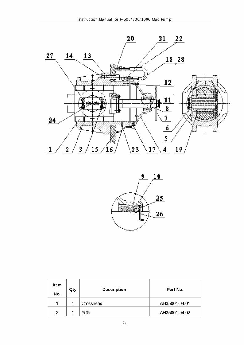
Instruction Manual for F-500/800/1000 Mud Pump
59
Item
No. Qty Description Part No.
1 1 Crosshead AH35001-04.01
2 1 导筒 AH35001-04.02

Instruction Manual for F-500/800/1000 Mud Pump
60
3 10 Cap screw3/8"×11UNC×38.1 T50-2004K
4 1 Diaphragm stuffing box AH35001-04.03
5 1 Crosshead pin AH35001-04.04
6 1 Crosshead retainer AH35001-04.05
7 1 Fluid baffle disk AH35001-04.06
8 1 锁紧弹簧 AH35001-04.07
9 1 油封环 AH35001-04.08
10 1 O-ring 95×5.3 GB3452.1-82
11 1 Crosshead extension AH35001-04.09
12 1 O-ring 305×3.55 GB3452.1
13 1 O-ring 71×5.3 GB3452.1
14 8 Cap screw 11/4"×8UNC T50-3005
15 1 Male connector AH35001-04.10
16 1 Rubber hose AH35001-04.11.00
17 1 弯头 AH35001-04.12
18 6 Cap screw 3/8"×16UNC T50-3002
19 1 Crosshead bearing AH35001-04.13
20 1 Male connector AH35001-04.14
21 1 Rubber hose AH35001-04.15.00
22 1 弯头 AH35001-04.16
23 1 Pipe plug AH35001-04.17
24 4 不锈钢丝 YB252-64
25 2 双唇油封 AH35001-04.18
26 1 O-ring GB3452.1
27 Loctite 242
28 6 弹簧垫圈子 10 GB93-76

Instruction Manual for F-500/800/1000 Mud Pump
61
F-800/1000 Crosshead Assembly

Instruction Manual for F-500/800/1000 Mud Pump
62
Item
No. Qty Description
Part No. F-800 F-100
1 1 Crosshead AH34001-04.01 AH33001-04.01
2 1 Crosshead guide (upper)
AH34001-04.02 AH33001-04.02
3 2 Cap screwT52-7008K 1"X60 1"X60 4 1 Diaphragm stuffing box AH34001-04.03 AH33001-04.03 5 1 O-ring GB3452.1 Ø128x7 Ø140X7 6 1 油封环 AH34001-04.05 AH33001-04.05 7 1 Fluid baffle disk AH34001-04.07 AH33001-04.07 8 1 Crosshead extension AH34001-04.08 AH33001-04.08 9 1 Crosshead pin AH34001-04.09 AH33001-04.09 10 6 Cap screwT52-7009K 1"x70 1"x70
11 1 Crosshead guide (lower)
AH34001-04.10 AH33001-04.10
12 8 Locking plate AH34001-04.11 AH33001-04.11 13 1 O-ring Ø160X3.55 Ø175X3.55 14 4 Cap screw 3/8"x25 GB5780-86 GB5780-86 15 1 锁紧弹簧 AH34001-04.12 AH33001-04.12 16 1 O-ring GB3452.1 Ø103x5.3 Ø125x7 17 8 Cap screw GB70-85 3/4"x65 3/4"x65 18 8 Shim set AH34001-04.16.00 AH33001-04.16.00 19 1 Gasket AH34001-04.13 AH33001-04.13 20 1 Crosshead pin retainer AH34001-04.14 AH33001-04.14 21 1 Crosshead bearing AH34001-04.15 AH33001-04.15
22 2 Male connector NPT3/8″x2
AH34001-04.06 AH33001-04.06
23 2 双唇油封 AH34001-04.17
4.5″x5.5″0.5″ AH33001-04.17 4.5″x5.5″x0.5″
24 8 Cap screwT52-6005K 1"x65 1"x65 25 按需 Safety wire Ø1.6 GB4240-84 GB4240-84 26 2 O-ring AH34001-04.04 AH33001-04.04 27 4 弹簧垫圈子 10 GB93-87 GB93-87 28 25ml Loctite 242 242

Instruction Manual for F-500/800/1000 Mud Pump
63
F-1000 Pinion Shaft Assembly

Instruction Manual for F-500/800/1000 Mud Pump
64
Item
No. Qty Description
Part No.
F-500 F-800 F-1000
1 1 Key AH35001-03.01 AH34001-03.01 AH33001-03.01
2 1 Pinion shaft AH35001-03.02 AH34001-03.02 AH33001-03.02A
3 2 Oil seal wear
ring AH35001-03.03 AH34001-03.03 AH33001-03.03
4 2 Oil seal carrier AH35001-03.04 AH34001-03.04 AH33001-03.04
5 2 Gasket AH35001-03.05 AH34001-03.05 AH33001-03.05
6 2 Gasket AH35001-03.06 AH34001-03.06 AH33001-03.06
7 2 Pinion bearing
carrier AH35001-03.07 AH34001-03.07 AH33001-03.07
8 12 Cap screw
GB5782 1/2"×35 1/2"×35 1/2"×35
9 16 Cap screw
GB5782 3/4"×50 7/8"×50 7/8"×50
10 2 Oil seal
AH35001-03.08
5.875″×7.25″×0.52
51″
AH34001-03.08
7.875″×9″×0.425″
AH33001-03.08
8.5″×10.5″×0.625″
11 2 Bearing AH35001-03.09 AH35001-03.09 AH33001-03.09
12 16 Locking washer
GB93 20 22 22
13 12 Locking washer
GB93 14 14 14
14 1 Axle-neck cover AH35001-03.10.00 AH34001-03.10.00 AH33001-03.10.00
15 1 Flange AH35001-03.11.00 AH34001-03.11.00 AH33001-03.11.00
16 3 Bolt GB5782 5/8"×45 5/8"×45 M16×45
17 3 Locking washer
GB93 16 16 16

Instruction Manual for F-500/800/1000 Mud Pump
65
F-1000 Crankshaft Assembly

Instruction Manual for F-500/800/1000 Mud Pump
66
Item
No. Qty Description
Part No. F-500 F-800 F-1000
1 2 Main bearing
cover AH35001-02.01 AH34001-02.01 AH33001-02.01
2 1 Bearing carrier,
left AH35001-02.02 AH34001-02.02 AH33001-02.02
3 2 Gasket, main bearing cover
AH35001-02.03 AH34001-02.03 AH33001-02.03
4 2 Inner race
retainer AH35001-02.04 AH34001-02.04 AH33001-02.04
5 3 Outer race
retainer AH35001-02.05 AH34001-02.05 AH33001-02.05
6 3 Eccentric strap AH35001-02.06 AH34001-02.06 AH33001-02.06
7 1 Inner race retainer(I)
AH35001-02.07 AH34001-02.07 AH33001-02.07
8 1 Crankshaft AH35001-02.08.00 AH34001-02.08.00 AH33001-02.08.00
9 1 Inner race retainer(II)
AH35001-02.09 AH34001-02.09 AH33001-02.09
10 1 Eccentric ring
gear AH35001-02.10A AH34001-02.10A AH33001-02.10A
11 12 Cap screw T50-2006 AH34001-02.15 AH33001-02.11
12 2 Spacer, main
bearing AH35001-02.12 AH34001-02.13 AH33001-02.13
13 1 Bearing carrier,
right AH35001-02.13 AH34001-02.14 AH33001-02.14
14 2 Outer race
retainer AH35001-02.14 —————— AH33001-02.15
压板法兰 —————— AH34001-02.11 ——————
15 2 Outer race
retainer AH35001-02.15 AH34001-02.16 AH33001-02.16
16 4 Housing bolt, main bearing
AH35001-02.17 —————— AH33001-02.17
主轴承双头螺栓 —————— AH33001-01.01.03 ——————
17 按
需 Shim set AH35001-02.18 AH34001-02.18 AH33001-02.18
18 4 Cap screw T50-1008K
5/8"×120 5/8"×120 5/8"×120
19 12 Locking nut AH35001-05.11.00 AH34001-05.12.00 AH33001-05.12.00
20 72 Cap screw T50-1008K
AH35001-02.16A 5/8"×40 5/8"×40

Instruction Manual for F-500/800/1000 Mud Pump
67
21 28 Cap screw T50-1008K
5/8"×45 5/8"×45
22 3 Eccentric bearing
AH35001-02.19.00 AH34001-02.19 AH33001-02.19
23 2 Bearing AH35001-02.16.00 AH34001-02.20 AH33001-02.20
24 28 Washer GB848 16 16 16
25 28m Safety wire
Ø1.5 GB343-82 GB343-82 GB343-82
26 40m Safety wireØ3 GB343-82 GB343-82 GB343-82 27 90 Loctite 242 242 242
28 28 Combination
packing washer JB982-77 JB982-77 JB982-77

Instruction Manual for F-500/800/1000 Mud Pump
68
F-1000 Lubrication Assembly
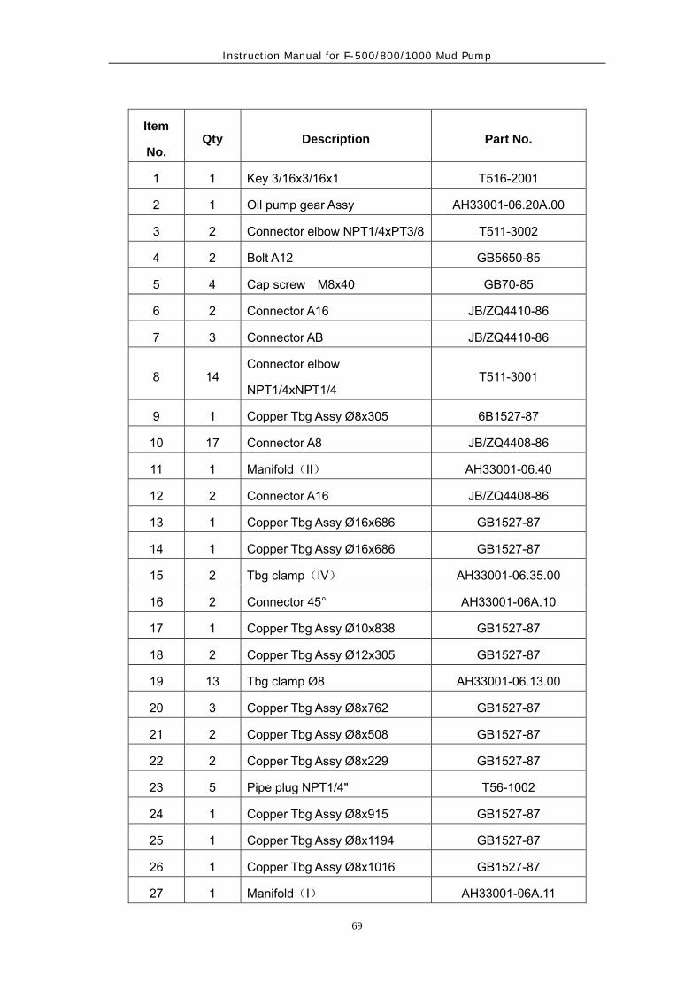
Instruction Manual for F-500/800/1000 Mud Pump
69
Item
No. Qty Description Part No.
1 1 Key 3/16x3/16x1 T516-2001
2 1 Oil pump gear Assy AH33001-06.20A.00
3 2 Connector elbow NPT1/4xPT3/8 T511-3002
4 2 Bolt A12 GB5650-85
5 4 Cap screw M8x40 GB70-85
6 2 Connector A16 JB/ZQ4410-86
7 3 Connector AB JB/ZQ4410-86
8 14 Connector elbow
NPT1/4xNPT1/4 T511-3001
9 1 Copper Tbg Assy Ø8x305 6B1527-87
10 17 Connector A8 JB/ZQ4408-86
11 1 Manifold(II) AH33001-06.40
12 2 Connector A16 JB/ZQ4408-86
13 1 Copper Tbg Assy Ø16x686 GB1527-87
14 1 Copper Tbg Assy Ø16x686 GB1527-87
15 2 Tbg clamp(IV) AH33001-06.35.00
16 2 Connector 45° AH33001-06A.10
17 1 Copper Tbg Assy Ø10x838 GB1527-87
18 2 Copper Tbg Assy Ø12x305 GB1527-87
19 13 Tbg clamp Ø8 AH33001-06.13.00
20 3 Copper Tbg Assy Ø8x762 GB1527-87
21 2 Copper Tbg Assy Ø8x508 GB1527-87
22 2 Copper Tbg Assy Ø8x229 GB1527-87
23 5 Pipe plug NPT1/4" T56-1002
24 1 Copper Tbg Assy Ø8x915 GB1527-87
25 1 Copper Tbg Assy Ø8x1194 GB1527-87
26 1 Copper Tbg Assy Ø8x1016 GB1527-87
27 1 Manifold(I) AH33001-06A.11

Instruction Manual for F-500/800/1000 Mud Pump
70
28 2 Connector A10 JB/ZQ4408-86
29 4 Tbg clamp〈I〉 AH33001-06.01.00
30 2 Washer A12 GB5651-85
31 4 Bolt M6x12 GB5781-86
32 2 Oil jet AH33001-06.10
33 2 Copper Tbg Assy Ø12x610 GB1527-87
34 2 Copper Tbg Assy Ø8x813 GB1527-87
35 2 Connector A8 GB5628.1.85
36 3 Tbg clamp-double Ø8 AH33001-06.04.00
37 1 Copper Tbg Assy Ø10x1956 GB1527-87
38 1 Copper Tbg Assy Ø8x1956 GB1527-87
39 1 Copper Tbg Assy Ø8x2311 GB1527-87
40 1 Copper Tbg Assy Ø8x1600 GB1527-87
41 1 Copper Tbg Assy Ø8x1245 GB1527-87
42 1 Connector NPT1/4x1/4x1.5 T513-1006
43 1 Copper washer 14 T514-1001
44 1 Shim set AH33001-06.06.00
45 1 Oil pump Mtg plate AH33001-06.19A
46 1 Connector A10 GB5628.1-85
47 4 Locking washer 8 GB93-87
48 1 Relief valve YYFJ-L20
49 4 Locking washer 6 GB93-87
50 1 Oil pump, 2S
51 1 Pressure gauge, M14x1.5
0-1.6MPa Y-60Z
52 4 Connector A12 JB/ZQ440B-86
53 1 Oil filter Assy AH33001-06A.33.00
54 Loctite 609 或 680

Instruction Manual for F-500/800/1000 Mud Pump
71
F-1000 Piston & Liner Wash

Instruction Manual for F-500/800/1000 Mud Pump
72
Item
No. Qty Description Part No.
1 1 Belt guard AH33001-088.01.00
AH33001-088.01.00A 2 1 Sheave AH33001-088.02 3 1 Support Assy AH33001-088.03.00 4 1 Connector NPT1-G1 AH33001-088.02 5 1 Connector NPT1 AH33001-088.04
6 1 Connector G1-M33x2 AH33001-08.03
7 1 Connector ZG2-1/2 AH33001-08A.07
8 1 Connector ZG21/2-NPT21/2
AH33001-08C.04
9 1 Hose Ø22xØ37 L=1500 10 2 Connector Ø22xØ37 AH33001-08.18.00 11 2 Elbow 90°NPT1 AH33001-08.16 12 2 Connector plate AH33001-088.06 13 1 Tank AH33001-08C.01.00 14 1 Tank cover AH33001-08C.02.00 15 1 Connector NPT21/2 AH34001-088.07 16 2 Washer AH33001-088.09 17 2 Flange NPT1″ AH33001-088.10
18 2 Locking capscrew M8x25
GB73-85
19 2 V-belt A3708 GB1171-74 20 2 Pipe clamp NO:3 21 1 Hose Ø38xØ53 L=750 22 1 Elbow 90°ZG21/2 23 4 Capscrew M20x30 GB5780-86 24 4 Locking washer20 GB93-87 25 8 Locking washer 20 GB95-85 26 4 Capscrew M12x40 GB5780-86 27 12 Washer 12 GB93-87 28 4 Washer 12 GB96-85 29 8 Capscrew M12x60 GB5780-86 30 8 Nut M12 GB41-86 31 1 Spraying pump AH33001-088.11.00 32 1 Globe valve G1 Q11F-16 33 1 Pump support AH33001-08C.03.00

Instruction Manual for F-500/800/1000 Mud Pump
73
F-1000 Spare Parts List
(以合同或技术协议为准)
Item
No.
Qt
y Description Part No.
F-500 F-800 F-1000
1 3 Valve cover seal
AH35001-05.08 AH33001-05.08 AH33001-05.08
2 3 Ring gasket R44
—————— T58-5002 T58-5002
3 2 Gasket AH35001-09 AH33001-09 AH33001-09 4 1 Bladder AH35001-5.35.02 AH33001-5.35.02 AH33001-5.35.02
5 1 Ring gasket R39
T5B-5001(3) T58-5001(1) T58-5001(1)
6 1 Bumper AH33003-06 AH33003-06 AH33003-06 7 1 Bladder AH35002-03.00 AH33002-03.00 AH33002-03.00 8 6 Head seal AH35001-05.04 AH33001-05.04 AH33001-05.04 9 3 Oil seal ring AH35001-04.08 AH34001-04.05 AH33001-04.05 10 2 Oil seal AH35001-03.08 AH34001-03.08 AH33001-03.08 11 6 Double oil seal AH35001-04.18 AH33001-04.017 AH33001-04.017
12 3 Piston rubberØ170
AH35001-05.15.06.02
AH33001-05.15.06.02
AH33001-05.15.06.02
13 6 Valve rubber AH35001-05.15.0
6 AH33001-05.15.06.
02 AH33001-05.15.06.
02 14 10 Shear pin AH33003-11A AH33003-11A AH33003-11A 15 1 Plunger seal AH33003-03.00 AH33003-03.00 AH33003-03.00 16 3 Piston seal —————— AH33001-05.17 AH33001-05.17
O-ring GB3452.1
Ø41.2×3.55 —————— ——————
17 3 O-ring GB3452.1
Ø75x5.3 Ø97.5x3.55 Ø97.5x3.55
18 3 O-ring GB3452.1
Ø150x7 Ø185x7 Ø185x7
19 3 O-ring GB3452.1
Ø71 x5.3 Ø103x5.3 Ø125x5.3
20 3 O-ring GB3452.1
Ø95x5.3 Ø128x7 Ø140x7
21 3 O-ring GB3452.1
—————— Ø160x3.55 Ø175x3.55
22 3 O-ring GB3452.1
Ø305x3.55 —————— ——————
23 2 O-ring GB3452.1
Ø355x3.55 —————— ——————

Instruction Manual for F-500/800/1000 Mud Pump
74
F-1000 Tool List
Item
No.
Despcription Part NO.
1 Hydraulic valve seat puller 1set
1 Air dome gas-filled flexible pipe assembly 1
3 Allen wrench 1set
4 Open-ended spanner 2

Instruction Manual for F-500/800/1000 Mud Pump
75
KB-75 Pulsation Dampener List
Part List
Description Part No. Page
KB-75 Pulsation Dampener AH33002-00 62
Pulsation Dampener Charging Hose & Instruction 64

Instruction Manual for F-500/800/1000 Mud Pump
76
KB-75 Pulsation Dampener

Instruction Manual for F-500/800/1000 Mud Pump
77
Item No. Qty Description Part No.
Drawing AH33002-00A
1 1 Sealing ring R39 T58-5001
2 1 Bottom plug AH33002-02
3 1 Bladder AH33002-03.00
4 1 Studded assembly AH33002-04A.00
5 1 Head AH33002-05A
6 1 Steel pipe tee
NPT1/4 AH33002-06
7 1 Close nipple
NPT1/4 AH33002-07
8 1 Gauge cover AH33002-08.00
9 1 Purge valve PJC1 –LB
10 1 Pressure gauge
(0-25Mpa) Y-60
11 1 Needle valve JZR3-L8
12 1 Washer T514-1001
R1 12 Stud T53-4002(AM39x2-M39x3x130)
R2 12 Nut T57-20011 (M39x3)
R3 8 Stud T53-4002(AM33x2-M33x3x100)
R4 8 Nut M33x3 T57-2009

Instruction Manual for F-500/800/1000 Mud Pump
78
Pulsation Dampener Charging Hose & Instruction
Item Qty Description Part No.
Pulsation dampener
charging hose AH33001-31.10.00
1 1 Nut G5/8″ AH33001-31.10.01
2 1 Sealing connector AH33001-31.10.02
3 1 Hose, C-type, M14x1.5 JB1887-77
4 1 Connector AH33001-31.10.03
5 1 Gasket AH33001-31.10.04
6 1 Pipe plug AH33001-31.10.05

Instruction Manual for F-500/800/1000 Mud Pump
79
JA-3 Shear relief
valve
AH33003-00
1 1 Adapter bushing AH33003-01
2 1 Plain washer AH33003-02
3 1 Plunger seal AH33003-03.00
4 1 Body AH33003-04
5 1 Plunger stem AH33003-05
6 1 Bumper AH33003-06
7 1 Roll pin AH33003-07
8 1 Cover spring AH33003-08
9 1 Cover AH33003-09
10 1 Shear bar AH33003-10
11 1 Shear pin AH33003-11A
12 1 Warning plate AH33003-12
13 1 Shear bar pin AH33003-13
14 2 Retainer ring AH33003-14
15 1 Name plate AH33003-15B
16 1 Cotter pin 4x26 GB91-86
17 2 Nut M4 GB41-86
18 2 Cap screw
M4x16
GB67-86
19 1 Bolt M10x110 GB5780-86
20 1 Nut M10 GB41-86
21 4 Cap screw M3x8 GB67-86

Instruction Manual for F-500/800/1000 Mud Pump
80