Embed Size (px)
Citation preview
This appliance shall be installed in accordance with:• Manufacturer’s Installation Instructions• Current AS/NZS 5601 AS/NZS 3000 • Local Regulations and Municipal Building Codes including local OH&S requirementsThis appliance must be installed, maintained and removed by an Authorised Person.For continued safety of this appliance it must be installed and maintained in accordance with the manufacturers instructions.
All Rinnai gas productsare A.G.A. certified.
RHFE-561FT RHFE-1005FTRHFE-309FTRHFE-559FT
The flue system installation instructions are enclosed with the flue terminal, packaged separately.NOTE
Operation & Installation ManualRHFE-309FT RHFE-559FT RHFE-561FT RHFE-1005FT
Rinnai 2 ES_FT_OIM
Congratulations on the purchase of your Rinnai Energysaver space heater.We trust you will have many years of comfort and enjoyment from your appliance.
BEFORE PROCEEDING WITH THE OPERATION OR INSTALLATION OF YOUR NEW HEATER PLEASE READ THIS MANUAL THOROUGHLY AND GAIN A FULL UNDERSTANDING OF THE
REQUIREMENTS, FEATURES AND OPERATION OF YOUR NEW APPLIANCE.
Rinnai 3 ES_FT_OIM
BEFORE YOU START ........................................................................................................................4INSTALLATION REQUIREMENTS .................................................................................................................. 4
CERTIFICATION .............................................................................................................................................. 4
FLUE INSTALLATION MANUAL ...................................................................................................................... 4
UNPACKING THE APPLIANCE ....................................................................................................................... 4
CARTON CONTENTS / ITEM CHECKLIST ..................................................................................................... 4
SAFETY ...............................................................................................................................................5
ABOUT YOUR ENERGY SAVER SPACE HEATER ..........................................................................8FEATURES....................................................................................................................................................... 8
CONTROL PANEL GENERAL LAYOUT .......................................................................................................... 9
BASIC HEATER OPERATION..........................................................................................................10TO TURN THE UNIT ‘ON’ .............................................................................................................................. 10
TO TURN THE UNIT ‘OFF’............................................................................................................................. 10
ROOM TEMPERATURE ADJUSTMENT ....................................................................................................... 10
ECONOMY MODE.......................................................................................................................................... 11
CHILD / FUNCTION LOCK............................................................................................................................. 11
FAN OPERATION........................................................................................................................................... 11
ADVANCED HEATER OPERATION.................................................................................................12SETTING THE CLOCK - RHFE-309FT / 559FT / 561FT ............................................................................... 12
SETTING THE CLOCK - RHFE-1005FT ........................................................................................................ 12
DAY LIGHT SAVING AND TIME ADJUSTMENT ALL MODELS ................................................................... 12
SETTING THE ON / OFF TIMERS - RHFE-309FT / 559FT / 561FT.............................................................. 13
OPERATING THE TIMERS - RHFE-309FT / 559FT / 561FT......................................................................... 13
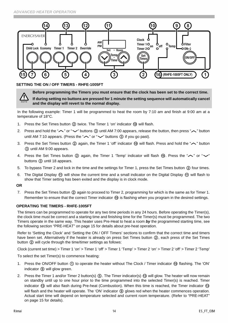
SETTING THE ON / OFF TIMERS - RHFE-1005FT ...................................................................................... 14
OPERATING THE TIMERS - RHFE-1005FT ................................................................................................. 14
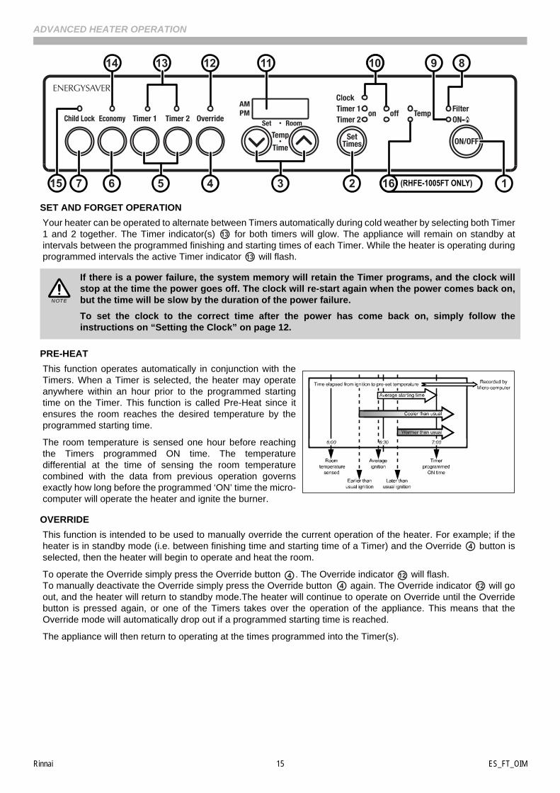
SET AND FORGET OPERATION .................................................................................................................. 15
PRE-HEAT...................................................................................................................................................... 15
OVERRIDE ..................................................................................................................................................... 15
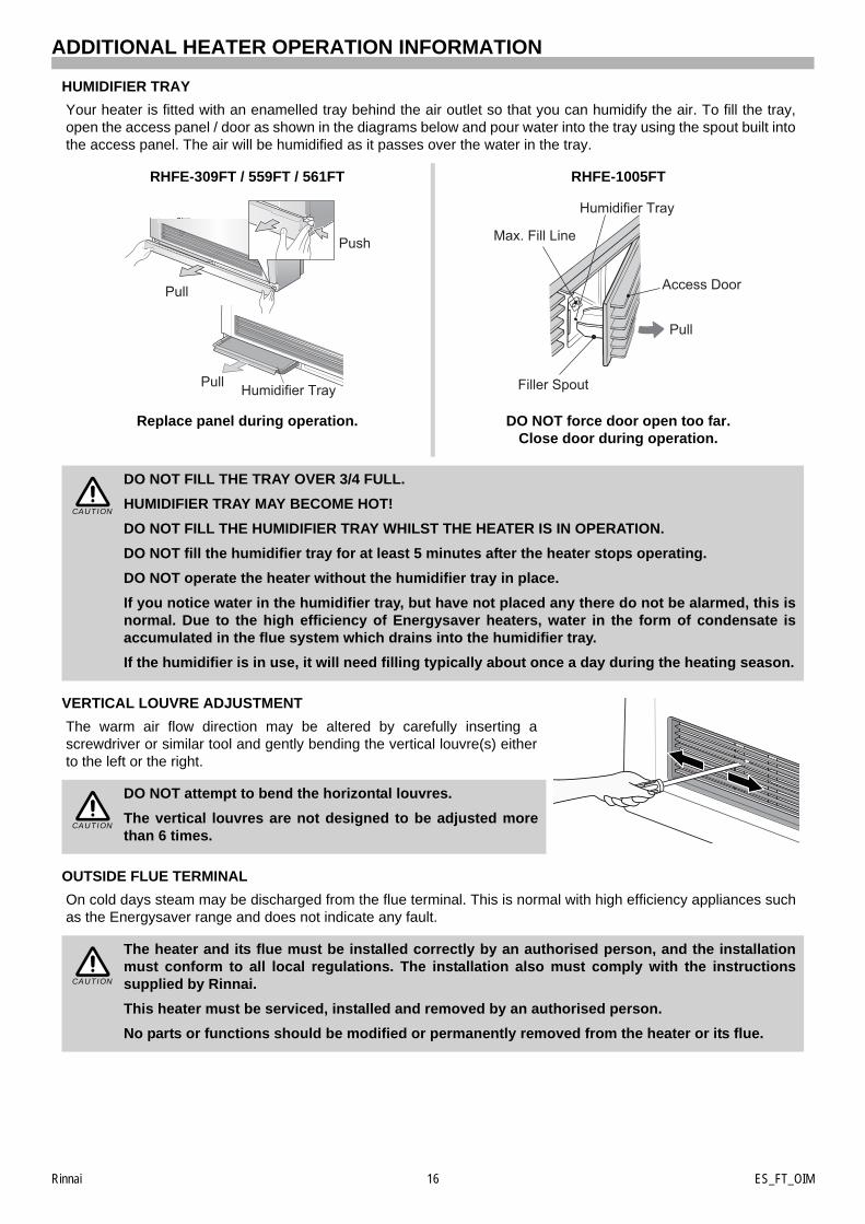
ADDITIONAL HEATER OPERATION INFORMATION ....................................................................16HUMIDIFIER TRAY ........................................................................................................................................ 16
VERTICAL LOUVRE ADJUSTMENT ............................................................................................................. 16
OUTSIDE FLUE TERMINAL........................................................................................................................... 16
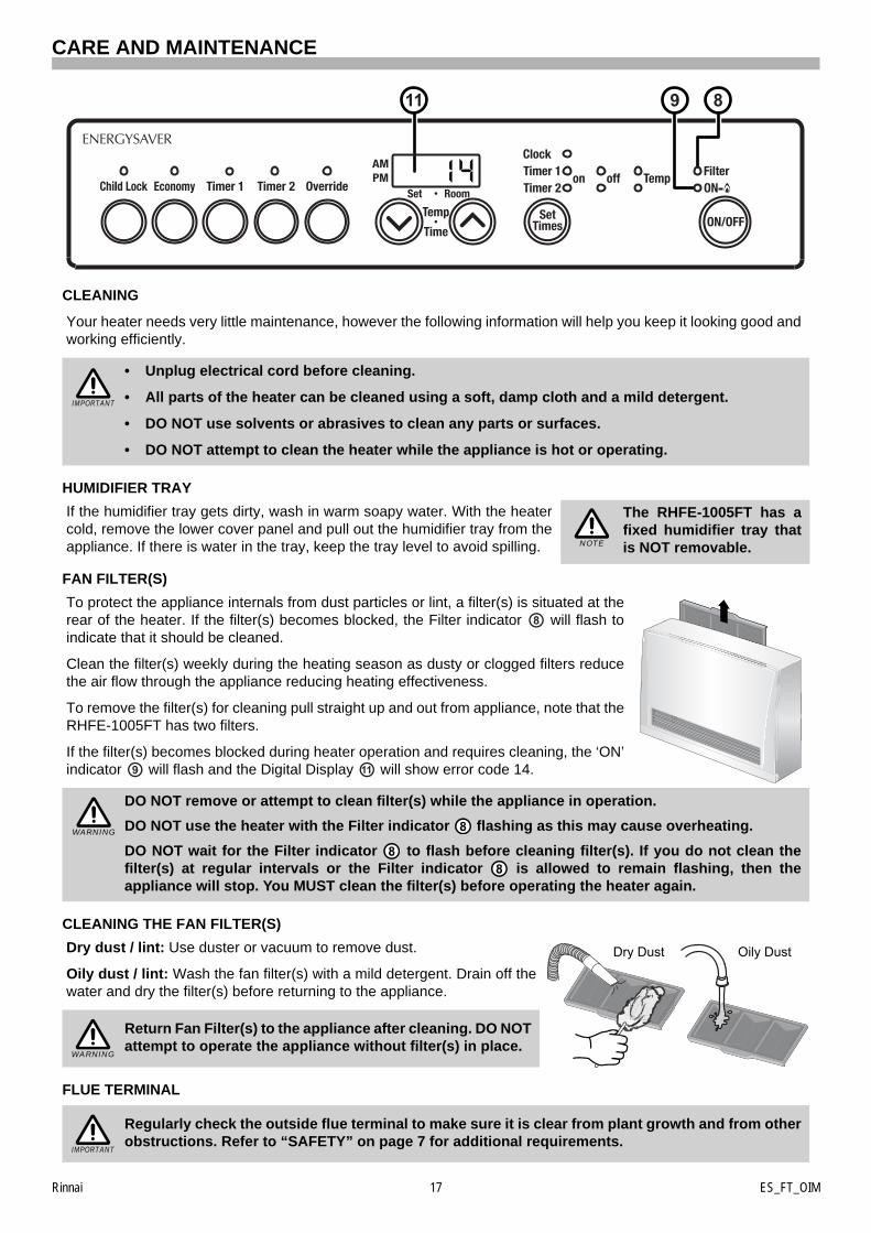
CARE AND MAINTENANCE.............................................................................................................17CLEANING...................................................................................................................................................... 17
HUMIDIFIER TRAY ........................................................................................................................................ 17
FAN FILTER(S)............................................................................................................................................... 17
CLEANING THE FAN FILTER(S) ................................................................................................................... 17
FLUE TERMINAL............................................................................................................................................ 17
SAVE A SERVICE CALL ................................................................................................................................ 18
SERVICE ........................................................................................................................................................ 18
TROUBLE SHOOTING CHECKLIST.............................................................................................................. 19
ERROR CODES ............................................................................................................................................. 19
INSTALLATION MANUAL ................................................................................................................21
CONTACT INFORMATION ...............................................................................................................36
OPERATION MANUAL

Rinnai 4 ES_FT_OIM
BEFORE YOU START
INSTALLATION REQUIREMENTS
This heater must be installed by an authorised person. The installation must conform to local regulations. Theinstallation must also comply with the instructions supplied by Rinnai.
Service and removal must be carried out by an authorised person.
CERTIFICATION
The Rinnai Energysaver® Range has been certified by the Australian Gas Association.
The AGA Certification Number is shown on the appliance dataplate.
No parts or functions should be modified or permanently removed from the heater.
Please keep these instructions in a safe place for future reference.
FLUE INSTALLATION MANUAL
These instructions are to be used in conjunction with the Rinnai “Energysaver Space Heater Co-Axial Flue SystemInstallation Manual” These components Installation Manual” supplied with flue kits ESDFK or ESKIT03.
UNPACKING THE APPLIANCE
Check for damage and missing parts. If the heater is damaged or missing any parts, contact your supplier foradvice.
Before installing the appliance, check it is labelled for the correct gas type (see label on the rear of heater).
Refer to local gas authority for confirmation of gas type if you are in doubt.
CARTON CONTENTS / ITEM CHECKLIST
Ensure that the components listed are present before proceeding with the installation.
* This component is supplied with the RHFE-309FT and RHFE-559FT and is ONLY for use with direct flue kit`ESDFK´ installations refer to page 27 for installation details.
Check you have the following:
1 x One of the following Rinnai Space Heaters
RHFE-309FT
RHFE-559FT
RHFE-561FT
RHFE-1005FT
1 x Rear Cover set, comprising of left, right and top cover panels
1 x Bolt pack containing; Part RHFE-309FTRHFE-559FTRHFE-561FT
RHFE-1005FT
Plastic inlet hose clamps 2 0
Air intake baffle ring* *1* 0
Flue adapter 0 1
Stainless steal sheath clamp Large 0 1
Stainless steal sheath clamp 1 0
Securing brackets 2 2
8g x 32mm screws 2 2
150mm long cable tie 1 1
Flue lock clamp L 0 1
Flue lock clamp S 1 1
6g x 10mm button head screws 2 0
6g x 8mm pan head screws 4 7
Rinnai 5 ES_FT_OIM
SAFETY
DO NOT MODIFY THIS APPLIANCE.
You MUST read and understand these instructions fully before operating the heater.
Failure to comply with these instructions could result in a fire or explosion, which could causeserious injury, death or property damage.
Improper installation, adjustments, service or maintenance can cause serious injury, death orproperty damage. Such work must be performed by an authorised person.
• Improper installation, adjustments, service or maintenance can cause serious injury, death orproperty damage. Such work must be performed by an authorised person.
• The appliance must be installed in accordance with the local gas and electrical authorityregulations.
• Flue terminal must always vent directly to outdoors.
• DO NOT extend the flue vertically or horizontally in ways other than prescribed in the appliancemanufacturers’ flue installation instructions.
• For information on gas consumption, see data plate on the appliance.
• This appliance must not be installed where curtains or other combustible materials could comeinto contact with it. In some cases curtains may need restraining.
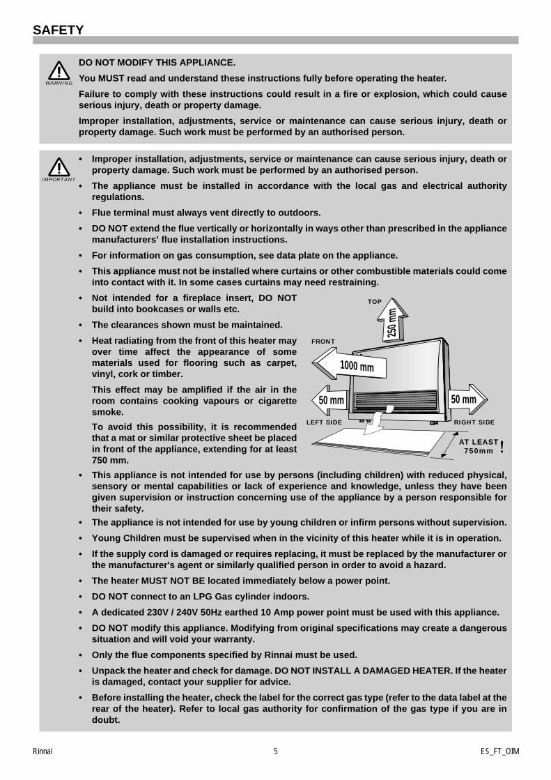
• Not intended for a fireplace insert, DO NOTbuild into bookcases or walls etc.
• The clearances shown must be maintained.
• Heat radiating from the front of this heater mayover time affect the appearance of somematerials used for flooring such as carpet,vinyl, cork or timber.
This effect may be amplified if the air in theroom contains cooking vapours or cigarettesmoke.
To avoid this possibility, it is recommendedthat a mat or similar protective sheet be placedin front of the appliance, extending for at least750 mm.
• This appliance is not intended for use by persons (including children) with reduced physical,sensory or mental capabilities or lack of experience and knowledge, unless they have beengiven supervision or instruction concerning use of the appliance by a person responsible fortheir safety.
• The appliance is not intended for use by young children or infirm persons without supervision.
• Young Children must be supervised when in the vicinity of this heater while it is in operation.
• If the supply cord is damaged or requires replacing, it must be replaced by the manufacturer orthe manufacturer's agent or similarly qualified person in order to avoid a hazard.
• The heater MUST NOT BE located immediately below a power point.
• DO NOT connect to an LPG Gas cylinder indoors.
• A dedicated 230V / 240V 50Hz earthed 10 Amp power point must be used with this appliance.
• DO NOT modify this appliance. Modifying from original specifications may create a dangeroussituation and will void your warranty.
• Only the flue components specified by Rinnai must be used.
• Unpack the heater and check for damage. DO NOT INSTALL A DAMAGED HEATER. If the heateris damaged, contact your supplier for advice.
• Before installing the heater, check the label for the correct gas type (refer to the data label at therear of the heater). Refer to local gas authority for confirmation of the gas type if you are indoubt.
WARNING
IMPORTANT
50 mm50 mm
TOP
LEFT SIDE RIGHT SIDE
AT LEAST750mm
1000 mm
250 m
m
FRONT
Rinnai 6 ES_FT_OIM
SAFETY
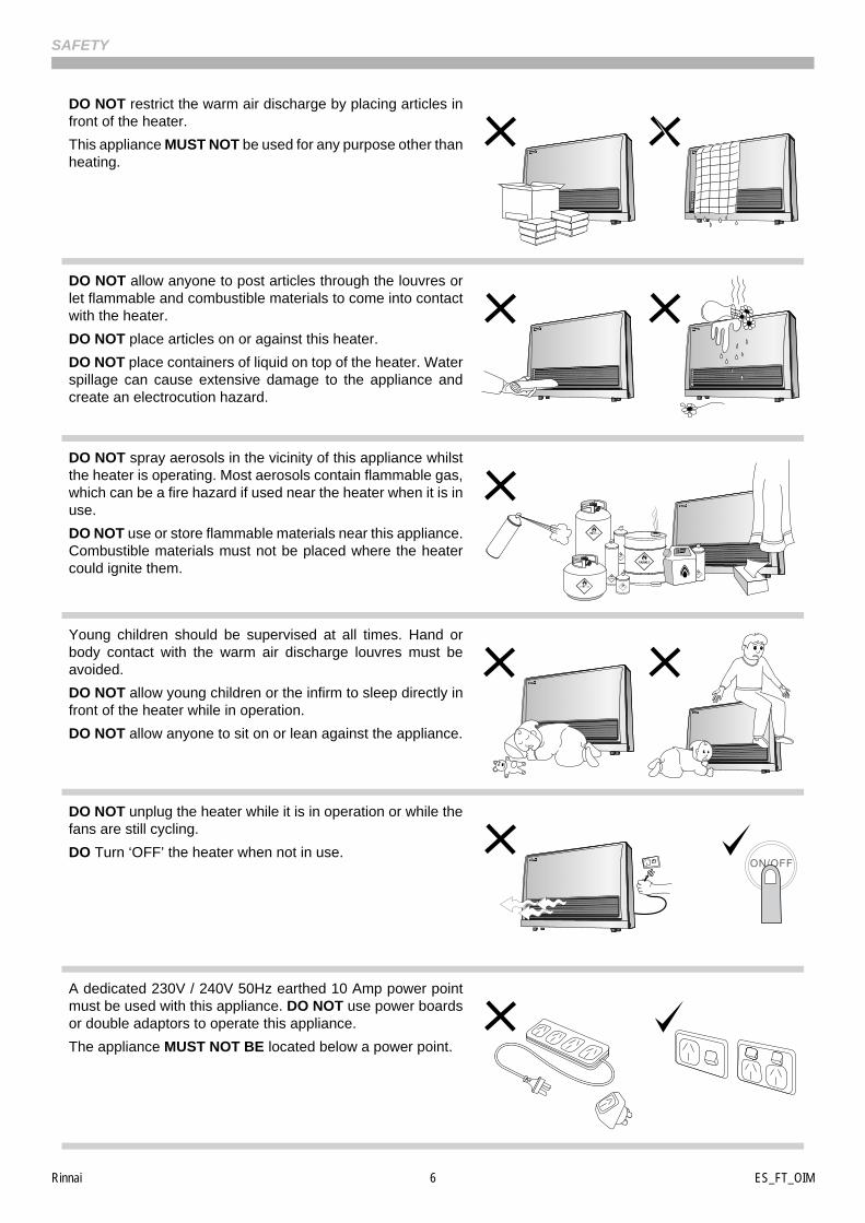
DO NOT restrict the warm air discharge by placing articles infront of the heater.
This appliance MUST NOT be used for any purpose other thanheating.
DO NOT allow anyone to post articles through the louvres orlet flammable and combustible materials to come into contactwith the heater.
DO NOT place articles on or against this heater.
DO NOT place containers of liquid on top of the heater. Waterspillage can cause extensive damage to the appliance andcreate an electrocution hazard.
DO NOT spray aerosols in the vicinity of this appliance whilstthe heater is operating. Most aerosols contain flammable gas,which can be a fire hazard if used near the heater when it is inuse.
DO NOT use or store flammable materials near this appliance.Combustible materials must not be placed where the heatercould ignite them.
Young children should be supervised at all times. Hand orbody contact with the warm air discharge louvres must beavoided.
DO NOT allow young children or the infirm to sleep directly infront of the heater while in operation.
DO NOT allow anyone to sit on or lean against the appliance.
DO NOT unplug the heater while it is in operation or while thefans are still cycling.
DO Turn ‘OFF’ the heater when not in use.
A dedicated 230V / 240V 50Hz earthed 10 Amp power pointmust be used with this appliance. DO NOT use power boardsor double adaptors to operate this appliance.
The appliance MUST NOT BE located below a power point.
Rinnai 7 ES_FT_OIM
SAFETY
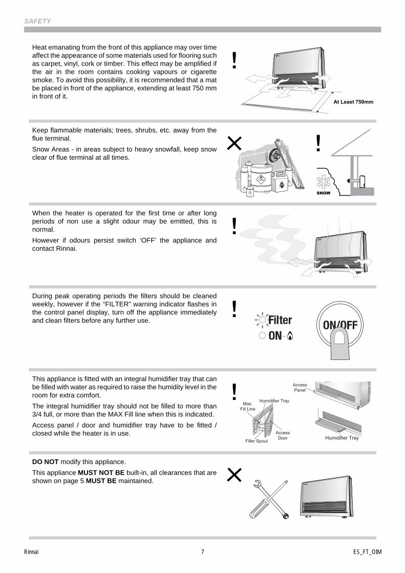
Heat emanating from the front of this appliance may over timeaffect the appearance of some materials used for flooring suchas carpet, vinyl, cork or timber. This effect may be amplified ifthe air in the room contains cooking vapours or cigarettesmoke. To avoid this possibility, it is recommended that a matbe placed in front of the appliance, extending at least 750 mmin front of it.
Keep flammable materials; trees, shrubs, etc. away from theflue terminal.
Snow Areas - in areas subject to heavy snowfall, keep snowclear of flue terminal at all times.
When the heater is operated for the first time or after longperiods of non use a slight odour may be emitted, this isnormal.
However if odours persist switch ‘OFF’ the appliance andcontact Rinnai.
During peak operating periods the filters should be cleanedweekly, however if the “FILTER” warning indicator flashes inthe control panel display, turn off the appliance immediatelyand clean filters before any further use.
This appliance is fitted with an integral humidifier tray that canbe filled with water as required to raise the humidity level in theroom for extra comfort.
The integral humidifier tray should not be filled to more than3/4 full, or more than the MAX Fill line when this is indicated.
Access panel / door and humidifier tray have to be fitted /closed while the heater is in use.
DO NOT modify this appliance.
This appliance MUST NOT BE built-in, all clearances that areshown on page 5 MUST BE maintained.
At Least 750mm
Humidifier Tray
AccessPanel
AccessDoor
Max.Fill Line
Humidifier Tray
Filler Spout
Rinnai 8 ES_FT_OIM
ABOUT YOUR ENERGY SAVER SPACE HEATER
FEATURES
Room Sealed:
Air for combustion is taken from the outside and the combustion products are exhausted to the outside. Thismeans heater operation has no effect on the composition and quality of air in the room.
Push Button Ignition:
Only one touch of the ‘ON’/’OFF’ button is required to operate the heater.
Child / Function Lock:
Prevents children from altering heater settings whilst running, or from activating the heater when turned ‘OFF’.
Memory:
The micro-computer records selected preset temperatures, the times programmed into Timers as well asoperating the Economy/Auto-Off and Pre-heat modes, to maintain comfort levels.
7 Step Automatic Heat Control:
Selected temperature is controlled via thermostat. The optimum corresponding fan speeds are controlled bythe Central Processing Unit.
Pre-heat:
This function will automatically operate the appliance before the programmed start time of the Timer, in orderto heat a room to the pre-set temperature by the programmed start time.
Economy Mode:
The economy mode function is an energy saving feature designed to control the room temperature andprevent discomfort from over heating.
Override Function:
This temporarily changes the heater operation from ‘ON’ to ‘OFF’, or vice versa, until the next programmedsetting is reached.
Dual Weekday / Weekend Timer:
The Dual WEEKDAY/WEEKEND Timer allows you to program the appliance to come on for two separateperiods each day, one period in the morning and one period in the evening.
The built in Pre-heat Mode brings the room temperature to the temperature you have selected, by the timeprogrammed into the Timer.
The Dual Timer feature means that you can "Set and Forget" your heater. It will turn itself ‘ON’ or to STANDBYat the times you have programmed until you cancel the Timer program.
Filter Indicator:
When the fan filters become covered with dust, the filter indicator will flash.
The filters should be vacuumed at regular intervals to avoid unnecessary strain on the appliance.
Humidifier Tray:
The integral humidifier tray can be filled with water as required to raise the humidity level in the room for extracomfort.
The integral humidifier tray should not be filled to more than 3/4 full, or more than the MAX Fill line when this isindicated.
Questions?
Contact Rinnai using the contact numbers listed on the back cover of this booklet for further advice.
Rinnai 9 ES_FT_OIM
ABOUT YOUR ENERGY SAVER SPACE HEATER
CONTROL PANEL GENERAL LAYOUT
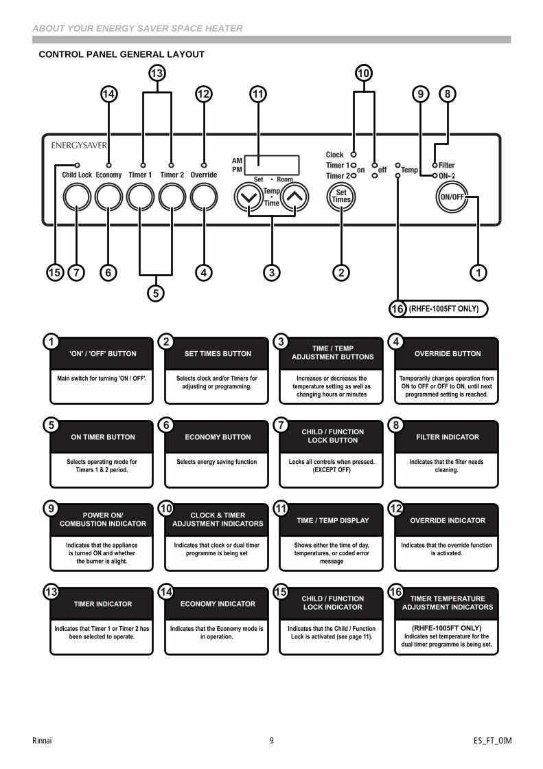
Main switch for turning 'ON / OFF'.
'ON' / 'OFF' BUTTON1
Selects clock and/or Timers foradjusting or programming.
SET TIMES BUTTON2
Temporarily changes operation fromON to OFF or OFF to ON, until next
programmed setting is reached.
OVERRIDE BUTTON4
Selects operating mode for Timers 1 & 2 period.
ON TIMER BUTTON5
Selects energy saving function
ECONOMY BUTTON6
Locks all controls when pressed. (EXCEPT OFF)
CHILD / FUNCTIONLOCK BUTTON
7
Indicates that the filter needs cleaning.
FILTER INDICATOR8
Increases or decreases the temperature setting as well as
changing hours or minutes
TIME / TEMPADJUSTMENT BUTTONS
3
Indicates that the applianceis turned ON and whether
the burner is alight.
POWER ON/COMBUSTION INDICATOR
9
Indicates that clock or dual timer programme is being set
CLOCK & TIMERADJUSTMENT INDICATORS
10
Shows either the time of day, temperatures, or coded error
message
TIME / TEMP DISPLAY11
(RHFE-1005FT ONLY)Indicates set temperature for the
dual timer programme is being set.
TIMER TEMPERATUREADJUSTMENT INDICATORS
16
Indicates that the override function is activated.
OVERRIDE INDICATOR12
Indicates that Timer 1 or Timer 2 has been selected to operate.
TIMER INDICATOR13
Indicates that the Economy mode is in operation.
ECONOMY INDICATOR14
Indicates that the Child / Function Lock is activated (see page 11).
CHILD / FUNCTIONLOCK INDICATOR
15
9
13
1214 11 8
10
127
5
15 6 4
(RHFE-1005FT ONLY)16
3
Rinnai 10 ES_FT_OIM
BASIC HEATER OPERATION
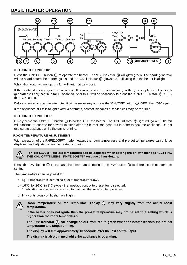
TO TURN THE UNIT ‘ON’
Press the ‘ON’/’OFF’ button to operate the heater. The ‘ON’ indicator will glow green. The spark generatorwill be heard before the burner ignites and the ‘ON’ indicator glows red, indicating that the heater is alight.
When the heater warms up, the fan will automatically start.
If the heater does not ignite on initial use, this may be due to air remaining in the gas supply line. The sparkgenerator will only continue for 15 seconds. After this it will be necessary to press the ‘ON’/’OFF’ button ‘OFF’,then ‘ON’ again.
Before a re-ignition can be attempted it will be necessary to press the 'ON'/'OFF' button 'OFF', then 'ON' again.
If the appliance still fails to ignite after 4 attempts, contact Rinnai as a service call may be required.
TO TURN THE UNIT ‘OFF’
Simply press the ‘ON’/’OFF’ button to switch ‘OFF’ the heater. The ‘ON’ indicator light will go out. The fanwill continue to operate for several minutes after the burner has gone out in order to cool the appliance. Do notunplug the appliance while the fan is running.
ROOM TEMPERATURE ADJUSTMENT
With exception of the RHFE1005FT model heaters the room temperature and pre-set temperatures can only bedisplayed and adjusted when the heater is running.
Press the “ ” button to increase the temperature setting or the “ ” button to decrease the temperaturesetting.
The temperatures can be preset to:
a) [L] - Temperature is controlled at set temperature “Low”.
b) [16°C] to [26°C] in 1°C steps - thermostatic control to preset temp selected.Combustion rate varies as required to maintain the selected temperature.
c) [H] - continuous combustion on ‘High’.
For RHFE1005FT the set temperature can be adjusted when setting the on/off timer see “SETTINGTHE ON / OFF TIMERS - RHFE-1005FT” on page 14 for details.
Room temperature on the Temp/Time Display may vary slightly from the actual roomtemperature.
If the heater does not ignite then the pre-set temperature may not be set to a setting which ishigher than the room temperature.
The ‘ON’ indicator will change colour from red to green when the heater reaches the pre-settemperature and stops running.
The display will dim approximately 10 seconds after the last control input.
The display is also dimmed while the appliance is operating.
913 1214 11 810
127 515 6 4 (RHFE-1005FT ONLY)163
NOTE
NOTE
Rinnai 11 ES_FT_OIM
BASIC HEATER OPERATION
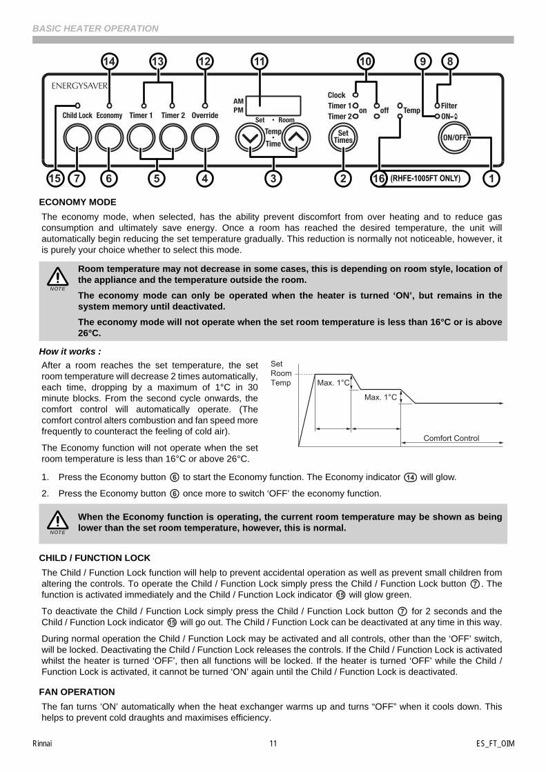
ECONOMY MODE
The economy mode, when selected, has the ability prevent discomfort from over heating and to reduce gasconsumption and ultimately save energy. Once a room has reached the desired temperature, the unit willautomatically begin reducing the set temperature gradually. This reduction is normally not noticeable, however, itis purely your choice whether to select this mode.
How it works :
After a room reaches the set temperature, the setroom temperature will decrease 2 times automatically,each time, dropping by a maximum of 1°C in 30minute blocks. From the second cycle onwards, thecomfort control will automatically operate. (Thecomfort control alters combustion and fan speed morefrequently to counteract the feeling of cold air).
The Economy function will not operate when the setroom temperature is less than 16°C or above 26°C.
1. Press the Economy button to start the Economy function. The Economy indicator will glow.
2. Press the Economy button once more to switch ‘OFF’ the economy function.
CHILD / FUNCTION LOCK
The Child / Function Lock function will help to prevent accidental operation as well as prevent small children fromaltering the controls. To operate the Child / Function Lock simply press the Child / Function Lock button . Thefunction is activated immediately and the Child / Function Lock indicator will glow green.
To deactivate the Child / Function Lock simply press the Child / Function Lock button for 2 seconds and theChild / Function Lock indicator will go out. The Child / Function Lock can be deactivated at any time in this way.
During normal operation the Child / Function Lock may be activated and all controls, other than the ‘OFF’ switch,will be locked. Deactivating the Child / Function Lock releases the controls. If the Child / Function Lock is activatedwhilst the heater is turned ‘OFF’, then all functions will be locked. If the heater is turned ‘OFF’ while the Child /Function Lock is activated, it cannot be turned ‘ON’ again until the Child / Function Lock is deactivated.
FAN OPERATION
The fan turns ‘ON’ automatically when the heat exchanger warms up and turns “OFF” when it cools down. Thishelps to prevent cold draughts and maximises efficiency.
Room temperature may not decrease in some cases, this is depending on room style, location ofthe appliance and the temperature outside the room.
The economy mode can only be operated when the heater is turned ‘ON’, but remains in thesystem memory until deactivated.
The economy mode will not operate when the set room temperature is less than 16°C or is above26°C.
When the Economy function is operating, the current room temperature may be shown as beinglower than the set room temperature, however, this is normal.
913 1214 11 810
127 515 6 4 (RHFE-1005FT ONLY)163
NOTE
SetRoomTemp Max. 1°C
Max. 1°C
Comfort Control
6 14
6
NOTE
715
715
Rinnai 12 ES_FT_OIM
ADVANCED HEATER OPERATION
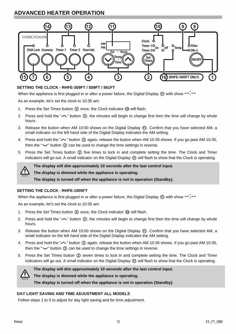
SETTING THE CLOCK - RHFE-309FT / 559FT / 561FT
When the appliance is first plugged in or after a power failure, the Digital Display with show --:--As an example, let’s set the clock to 10:35 am:
1. Press the Set Times button once, the Clock indicator will flash.
2. Press and hold the “ ” button ; the minutes will begin to change first then the time will change by wholehours.
3. Release the button when AM 10:00 shows on the Digital Display . Confirm that you have selected AM, asmall indicator on the left hand side of the Digital Display indicates the AM setting.
4. Press and hold the “ ” button again, release the button when AM 10:35 shows. If you go past AM 10:35,
then the “ ” button can be used to change the time settings in reverse.
5. Press the Set Times button five times to lock in and complete setting the time. The Clock and Timerindicators will go out. A small indicator on the Digital Display will flash to show that the Clock is operating.
SETTING THE CLOCK - RHFE-1005FT
When the appliance is first plugged in or after a power failure, the Digital Display with show --:--As an example, let’s set the clock to 10:35 am:
1. Press the Set Times button once, the Clock indicator will flash.
2. Press and hold the “ ” button ; the minutes will begin to change first then the time will change by wholehours.
3. Release the button when AM 10:00 shows on the Digital Display . Confirm that you have selected AM, asmall indicator on the left hand side of the Digital Display indicates the AM setting.
4. Press and hold the “ ” button again, release the button when AM 10:35 shows. If you go past AM 10:35,then the “ ” button can be used to change the time settings in reverse.
5. Press the Set Times button seven times to lock in and complete setting the time. The Clock and Timerindicators will go out. A small indicator on the Digital Display will flash to show that the Clock is operating.
DAY LIGHT SAVING AND TIME ADJUSTMENT ALL MODELS
Follow steps 1 to 5 to adjust for day light saving and for time adjustment.
The display will dim approximately 10 seconds after the last control input.
The display is dimmed while the appliance is operating.
The display is turned off when the appliance is not in operation (Standby).
The display will dim approximately 10 seconds after the last control input.
The display is dimmed while the appliance is operating.
The display is turned off when the appliance is not in operation (Standby).
913 1214 11 810
127 515 6 4 (RHFE-1005FT ONLY)163
11
2 10
11
2
11
NOTE
11
2 10
11
2
11
NOTE
Rinnai 13 ES_FT_OIM
ADVANCED HEATER OPERATION
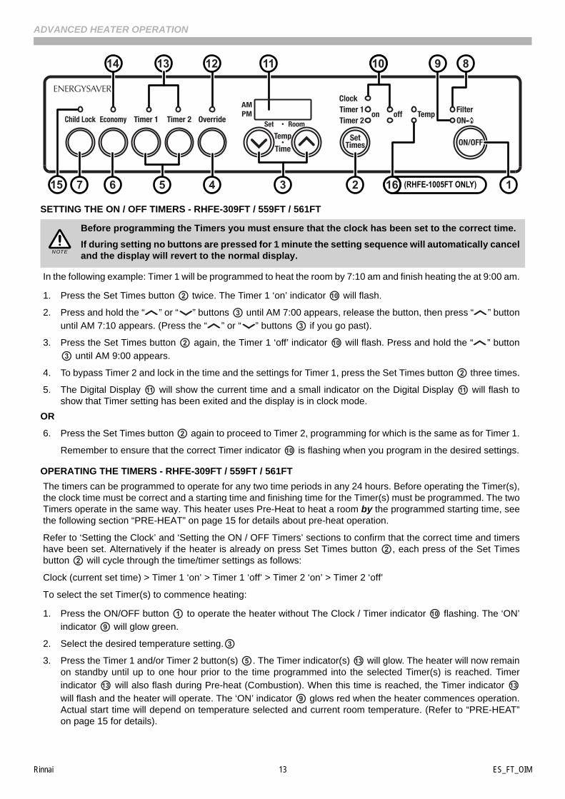
SETTING THE ON / OFF TIMERS - RHFE-309FT / 559FT / 561FT
In the following example: Timer 1 will be programmed to heat the room by 7:10 am and finish heating the at 9:00 am.
1. Press the Set Times button twice. The Timer 1 ‘on’ indicator will flash.
2. Press and hold the “ ” or “ ” buttons until AM 7:00 appears, release the button, then press “ ” button
until AM 7:10 appears. (Press the “ ” or “ ” buttons if you go past).
3. Press the Set Times button again, the Timer 1 ‘off’ indicator will flash. Press and hold the “ ” button
until AM 9:00 appears.
4. To bypass Timer 2 and lock in the time and the settings for Timer 1, press the Set Times button three times.
5. The Digital Display will show the current time and a small indicator on the Digital Display will flash toshow that Timer setting has been exited and the display is in clock mode.
OR
6. Press the Set Times button again to proceed to Timer 2, programming for which is the same as for Timer 1.
Remember to ensure that the correct Timer indicator is flashing when you program in the desired settings.
OPERATING THE TIMERS - RHFE-309FT / 559FT / 561FT
The timers can be programmed to operate for any two time periods in any 24 hours. Before operating the Timer(s),the clock time must be correct and a starting time and finishing time for the Timer(s) must be programmed. The twoTimers operate in the same way. This heater uses Pre-Heat to heat a room by the programmed starting time, seethe following section “PRE-HEAT” on page 15 for details about pre-heat operation.
Refer to ‘Setting the Clock’ and ‘Setting the ON / OFF Timers’ sections to confirm that the correct time and timershave been set. Alternatively if the heater is already on press Set Times button , each press of the Set Timesbutton will cycle through the time/timer settings as follows:
Clock (current set time) > Timer 1 ‘on’ > Timer 1 ‘off’ > Timer 2 ‘on’ > Timer 2 ‘off’
To select the set Timer(s) to commence heating:
1. Press the ON/OFF button to operate the heater without The Clock / Timer indicator flashing. The ‘ON’indicator will glow green.
2. Select the desired temperature setting.
3. Press the Timer 1 and/or Timer 2 button(s) . The Timer indicator(s) will glow. The heater will now remainon standby until up to one hour prior to the time programmed into the selected Timer(s) is reached. Timerindicator will also flash during Pre-heat (Combustion). When this time is reached, the Timer indicator will flash and the heater will operate. The ‘ON’ indicator glows red when the heater commences operation.Actual start time will depend on temperature selected and current room temperature. (Refer to “PRE-HEAT”on page 15 for details).
Before programming the Timers you must ensure that the clock has been set to the correct time.
If during setting no buttons are pressed for 1 minute the setting sequence will automatically canceland the display will revert to the normal display.
913 1214 11 810
127 515 6 4 (RHFE-1005FT ONLY)163
NOTE
2 10
2 10
2
11 11
2
10
22
10
5 13
13 13
Rinnai 14 ES_FT_OIM
ADVANCED HEATER OPERATION
SETTING THE ON / OFF TIMERS - RHFE-1005FT
In the following example: Timer 1 will be programmed to heat the room by 7:10 am and finish at 9:00 am at atemperature of 18°C.
1. Press the Set Times button twice. The Timer 1 ‘on’ indicator will flash.
2. Press and hold the “ ” or “ ” buttons until AM 7:00 appears, release the button, then press “ ” button
until AM 7:10 appears. (Press the “ ” or “ ” buttons if you go past).
3. Press the Set Times button again, the Timer 1 ‘off’ indicator will flash. Press and hold the “ ” button until AM 9:00 appears.
4. Press the Set Times button again, the Timer 1 ‘Temp’ indicator will flash . Press the “ ” or “ ”buttons until 18 appears.
5. To bypass Timer 2 and lock in the time and the settings for Timer 1, press the Set Times button four times.
6. The Digital Display will show the current time and a small indicator on the Digital Display will flash toshow that Timer setting has been exited and the display is in clock mode.
OR
7. Press the Set Times button again to proceed to Timer 2, programming for which is the same as for Timer 1.Remember to ensure that the correct Timer indicator is flashing when you program in the desired settings.
OPERATING THE TIMERS - RHFE-1005FT
The timers can be programmed to operate for any two time periods in any 24 hours. Before operating the Timer(s),the clock time must be correct and a starting time and finishing time for the Timer(s) must be programmed. The twoTimers operate in the same way. This heater uses Pre-Heat to heat a room by the programmed starting time, seethe following section “PRE-HEAT” on page 15 for details about pre-heat operation.
Refer to ‘Setting the Clock’ and ‘Setting the ON / OFF Timers’ sections to confirm that the correct time and timershave been set. Alternatively if the heater is already on press Set Times button , each press of the Set Timesbutton will cycle through the time/timer settings as follows:
Clock (current set time) > Timer 1 ‘on’ > Timer 1 ‘off’ > Timer 1 ‘Temp’ > Timer 2 ‘on’ > Timer 2 ‘off’ > Timer 2 ‘Temp’
To select the set Timer(s) to commence heating:
1. Press the ON/OFF button to operate the heater without The Clock / Timer indicator flashing. The ‘ON’
indicator will glow green.
2. Press the Timer 1 and/or Timer 2 button(s) . The Timer indicator(s) will glow. The heater will now remainon standby until up to one hour prior to the time programmed into the selected Timer(s) is reached. Timer
indicator will also flash during Pre-heat (Combustion). When this time is reached, the Timer indicator will flash and the heater will operate. The ‘ON’ indicator glows red when the heater commences operation.Actual start time will depend on temperature selected and current room temperature. (Refer to “PRE-HEAT”on page 15 for details).
Before programming the Timers you must ensure that the clock has been set to the correct time.
If during setting no buttons are pressed for 1 minute the setting sequence will automatically canceland the display will revert to the normal display.
913 1214 11 810
127 515 6 4 (RHFE-1005FT ONLY)163
NOTE
2 10
2 10
2 16
2
11 11
2
10
22
10
5 13
13 13
Rinnai 15 ES_FT_OIM
ADVANCED HEATER OPERATION
SET AND FORGET OPERATION
Your heater can be operated to alternate between Timers automatically during cold weather by selecting both Timer1 and 2 together. The Timer indicator(s) for both timers will glow. The appliance will remain on standby atintervals between the programmed finishing and starting times of each Timer. While the heater is operating duringprogrammed intervals the active Timer indicator will flash.
PRE-HEAT
This function operates automatically in conjunction with theTimers. When a Timer is selected, the heater may operateanywhere within an hour prior to the programmed startingtime on the Timer. This function is called Pre-Heat since itensures the room reaches the desired temperature by theprogrammed starting time.
The room temperature is sensed one hour before reachingthe Timers programmed ON time. The temperaturedifferential at the time of sensing the room temperaturecombined with the data from previous operation governsexactly how long before the programmed ‘ON’ time the micro-computer will operate the heater and ignite the burner.
OVERRIDE
This function is intended to be used to manually override the current operation of the heater. For example; if theheater is in standby mode (i.e. between finishing time and starting time of a Timer) and the Override button isselected, then the heater will begin to operate and heat the room.
To operate the Override simply press the Override button . The Override indicator will flash.To manually deactivate the Override simply press the Override button again. The Override indicator will goout, and the heater will return to standby mode.The heater will continue to operate on Override until the Overridebutton is pressed again, or one of the Timers takes over the operation of the appliance. This means that theOverride mode will automatically drop out if a programmed starting time is reached.
The appliance will then return to operating at the times programmed into the Timer(s).
If there is a power failure, the system memory will retain the Timer programs, and the clock willstop at the time the power goes off. The clock will re-start again when the power comes back on,but the time will be slow by the duration of the power failure.
To set the clock to the correct time after the power has come back on, simply follow theinstructions on “Setting the Clock” on page 12.
913 1214 11 810
127 515 6 4 (RHFE-1005FT ONLY)163
13
13
NOTE
4
4 124 12
Rinnai 16 ES_FT_OIM
ADDITIONAL HEATER OPERATION INFORMATION
HUMIDIFIER TRAY
Your heater is fitted with an enamelled tray behind the air outlet so that you can humidify the air. To fill the tray,open the access panel / door as shown in the diagrams below and pour water into the tray using the spout built intothe access panel. The air will be humidified as it passes over the water in the tray.
VERTICAL LOUVRE ADJUSTMENT
The warm air flow direction may be altered by carefully inserting ascrewdriver or similar tool and gently bending the vertical louvre(s) eitherto the left or the right.
OUTSIDE FLUE TERMINAL
On cold days steam may be discharged from the flue terminal. This is normal with high efficiency appliances suchas the Energysaver range and does not indicate any fault.
RHFE-309FT / 559FT / 561FT
Replace panel during operation.
RHFE-1005FT
DO NOT force door open too far. Close door during operation.
DO NOT FILL THE TRAY OVER 3/4 FULL.
HUMIDIFIER TRAY MAY BECOME HOT!
DO NOT FILL THE HUMIDIFIER TRAY WHILST THE HEATER IS IN OPERATION.
DO NOT fill the humidifier tray for at least 5 minutes after the heater stops operating.
DO NOT operate the heater without the humidifier tray in place.
If you notice water in the humidifier tray, but have not placed any there do not be alarmed, this isnormal. Due to the high efficiency of Energysaver heaters, water in the form of condensate isaccumulated in the flue system which drains into the humidifier tray.
If the humidifier is in use, it will need filling typically about once a day during the heating season.
DO NOT attempt to bend the horizontal louvres.
The vertical louvres are not designed to be adjusted morethan 6 times.
The heater and its flue must be installed correctly by an authorised person, and the installationmust conform to all local regulations. The installation also must comply with the instructionssupplied by Rinnai.
This heater must be serviced, installed and removed by an authorised person.
No parts or functions should be modified or permanently removed from the heater or its flue.
Pull
Push
Pull Humidifier Tray
Access Door
Max. Fill Line
Humidifier Tray
Filler Spout
Pull
CAUTION
CAUTION
CAUTION
Rinnai 17 ES_FT_OIM
CARE AND MAINTENANCE
CLEANING
Your heater needs very little maintenance, however the following information will help you keep it looking good andworking efficiently.
HUMIDIFIER TRAY
If the humidifier tray gets dirty, wash in warm soapy water. With the heatercold, remove the lower cover panel and pull out the humidifier tray from theappliance. If there is water in the tray, keep the tray level to avoid spilling.
FAN FILTER(S)
To protect the appliance internals from dust particles or lint, a filter(s) is situated at therear of the heater. If the filter(s) becomes blocked, the Filter indicator will flash toindicate that it should be cleaned.
Clean the filter(s) weekly during the heating season as dusty or clogged filters reducethe air flow through the appliance reducing heating effectiveness.
To remove the filter(s) for cleaning pull straight up and out from appliance, note that theRHFE-1005FT has two filters.
If the filter(s) becomes blocked during heater operation and requires cleaning, the ‘ON’indicator will flash and the Digital Display will show error code 14.
CLEANING THE FAN FILTER(S)
Dry dust / lint: Use duster or vacuum to remove dust.
Oily dust / lint: Wash the fan filter(s) with a mild detergent. Drain off thewater and dry the filter(s) before returning to the appliance.
FLUE TERMINAL
• Unplug electrical cord before cleaning.
• All parts of the heater can be cleaned using a soft, damp cloth and a mild detergent.
• DO NOT use solvents or abrasives to clean any parts or surfaces.
• DO NOT attempt to clean the heater while the appliance is hot or operating.
DO NOT remove or attempt to clean filter(s) while the appliance in operation.
DO NOT use the heater with the Filter indicator flashing as this may cause overheating.
DO NOT wait for the Filter indicator to flash before cleaning filter(s). If you do not clean thefilter(s) at regular intervals or the Filter indicator is allowed to remain flashing, then theappliance will stop. You MUST clean the filter(s) before operating the heater again.
Return Fan Filter(s) to the appliance after cleaning. DO NOTattempt to operate the appliance without filter(s) in place.
Regularly check the outside flue terminal to make sure it is clear from plant growth and from otherobstructions. Refer to “SAFETY” on page 7 for additional requirements.
911 8
IMPORTANT
8
11
WARNING
Dry Dust Oily Dust
WARNING
IMPORTANT
The RHFE-1005FT has afixed humidifier tray thatis NOT removable.NOTE
Rinnai 18 ES_FT_OIM
CARE AND MAINTENANCE
SAVE A SERVICE CALL
SERVICE
Rinnai recommend that this appliance and installation be inspected and serviced every 2 years.
If the power supply cord or any other component of the heater are damaged, they must be replaced by Rinnai or asuitably qualified person.
Any service or repair work should only be carried out by an authorised person. Rinnai has service and spare partsdepartments nationally, see back cover for contact details.
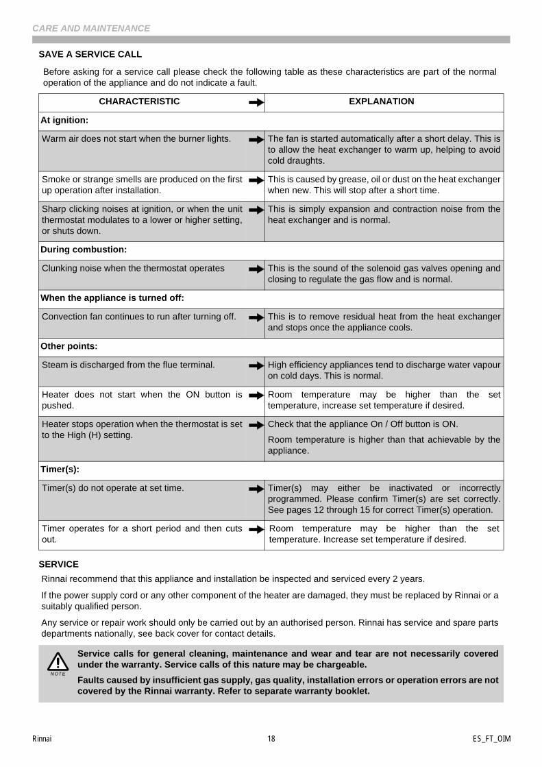
Before asking for a service call please check the following table as these characteristics are part of the normaloperation of the appliance and do not indicate a fault.
CHARACTERISTIC EXPLANATION
At ignition:
Warm air does not start when the burner lights. The fan is started automatically after a short delay. This isto allow the heat exchanger to warm up, helping to avoidcold draughts.
Smoke or strange smells are produced on the firstup operation after installation.
This is caused by grease, oil or dust on the heat exchangerwhen new. This will stop after a short time.
Sharp clicking noises at ignition, or when the unitthermostat modulates to a lower or higher setting,or shuts down.
This is simply expansion and contraction noise from theheat exchanger and is normal.
During combustion:
Clunking noise when the thermostat operates This is the sound of the solenoid gas valves opening andclosing to regulate the gas flow and is normal.
When the appliance is turned off:
Convection fan continues to run after turning off. This is to remove residual heat from the heat exchangerand stops once the appliance cools.
Other points:
Steam is discharged from the flue terminal. High efficiency appliances tend to discharge water vapouron cold days. This is normal.
Heater does not start when the ON button ispushed.
Room temperature may be higher than the settemperature, increase set temperature if desired.
Heater stops operation when the thermostat is setto the High (H) setting.
Check that the appliance On / Off button is ON.
Room temperature is higher than that achievable by theappliance.
Timer(s):
Timer(s) do not operate at set time. Timer(s) may either be inactivated or incorrectlyprogrammed. Please confirm Timer(s) are set correctly.See pages 12 through 15 for correct Timer(s) operation.
Timer operates for a short period and then cutsout.
Room temperature may be higher than the settemperature. Increase set temperature if desired.
Service calls for general cleaning, maintenance and wear and tear are not necessarily coveredunder the warranty. Service calls of this nature may be chargeable.
Faults caused by insufficient gas supply, gas quality, installation errors or operation errors are notcovered by the Rinnai warranty. Refer to separate warranty booklet.
NOTE
Rinnai 19 ES_FT_OIM
CARE AND MAINTENANCE
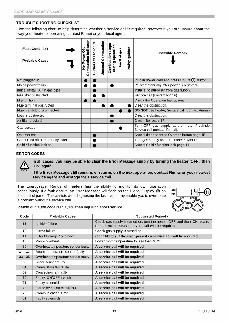
TROUBLE SHOOTING CHECKLIST
Use the following chart to help determine whether a service call is required, however if you are unsure about theway your heater is operating, contact Rinnai or your local agent.
ERROR CODES
The Energysaver Range of heaters has the ability to monitor its own operationcontinuously. If a fault occurs, an Error Message will flash on the Digital Display onthe control panel. This assists with diagnosing the fault, and may enable you to overcomea problem without a service call.
Please quote the code displayed when inquiring about service.
Fault Condition
Probable Cause
No
Po
wer
ON
/C
om
bu
stio
n In
dic
ato
r
Bu
rner
s fa
il to
ign
ite
Un
usu
al C
om
bu
stio
n
Co
mb
us
tio
n s
top
sd
uri
ng
op
erat
ion
Sm
ell o
f g
as
No
isy
Ign
itio
n
Possible Remedy
Not plugged in Plug in power cord and press On/Off button.
Mains power failure Re-start manually after power is restored.
(Initial Install) Air in gas pipe Installer to purge air from gas supply.
Gas filter obstructed Service call (contact Rinnai).
Mis-Ignition Check the Operation Instructions.
Flue terminal obstructed Clear the obstruction.
Flue manifold disconnected DO NOT use heater, Service call (contact Rinnai).
Louvre obstructed Clear the obstruction.
Air filter blocked. Clean filter page 17
Gas escapeTurn OFF gas supply at the meter / cylinder,Service call (contact Rinnai).
On timer set Cancel timer or press Override button page 15.
Gas turned off at meter / cylinder Turn gas supply on at the meter / cylinder.
Child / function lock set Cancel Child / function lock page 11
In all cases, you may be able to clear the Error Message simply by turning the heater ‘OFF’, then‘ON’ again.
If the Error Message still remains or returns on the next operation, contact Rinnai or your nearestservice agent and arrange for a service call.
Code Probable Cause Suggested Remedy
11 Ignition failureCheck gas supply is turned on, turn the heater ‘OFF’ and then ‘ON’ again.If the error persists a service call will be required.
12 Flame failure Check gas supply is turned on.
14 Filter blockage / overheat Clean filter(s). If the error persists a service call will be required.
16 Room overheat Lower room temperature to less than 40°C.
30 Overheat temperature sensor faulty A service call will be required.
31 - 32 Room temperature sensor faulty A service call will be required.
33 - 35 Overheat temperature sensor faulty A service call will be required.
53 Spark sensor faulty A service call will be required.
61 Combustion fan faulty A service call will be required.
62 Convection fan faulty A service call will be required.
70 Faulty ‘ON/OFF’ switch A service call will be required.
71 Faulty solenoids A service call will be required.
72 Flame detection circuit fault A service call will be required.
73 Communication error A service call will be required.
81 Faulty solenoids A service call will be required.
1
NOTE
1111

Rinnai 20 ES_FT_OIM
NOTES
Rinnai 21 ES_FT_OIM
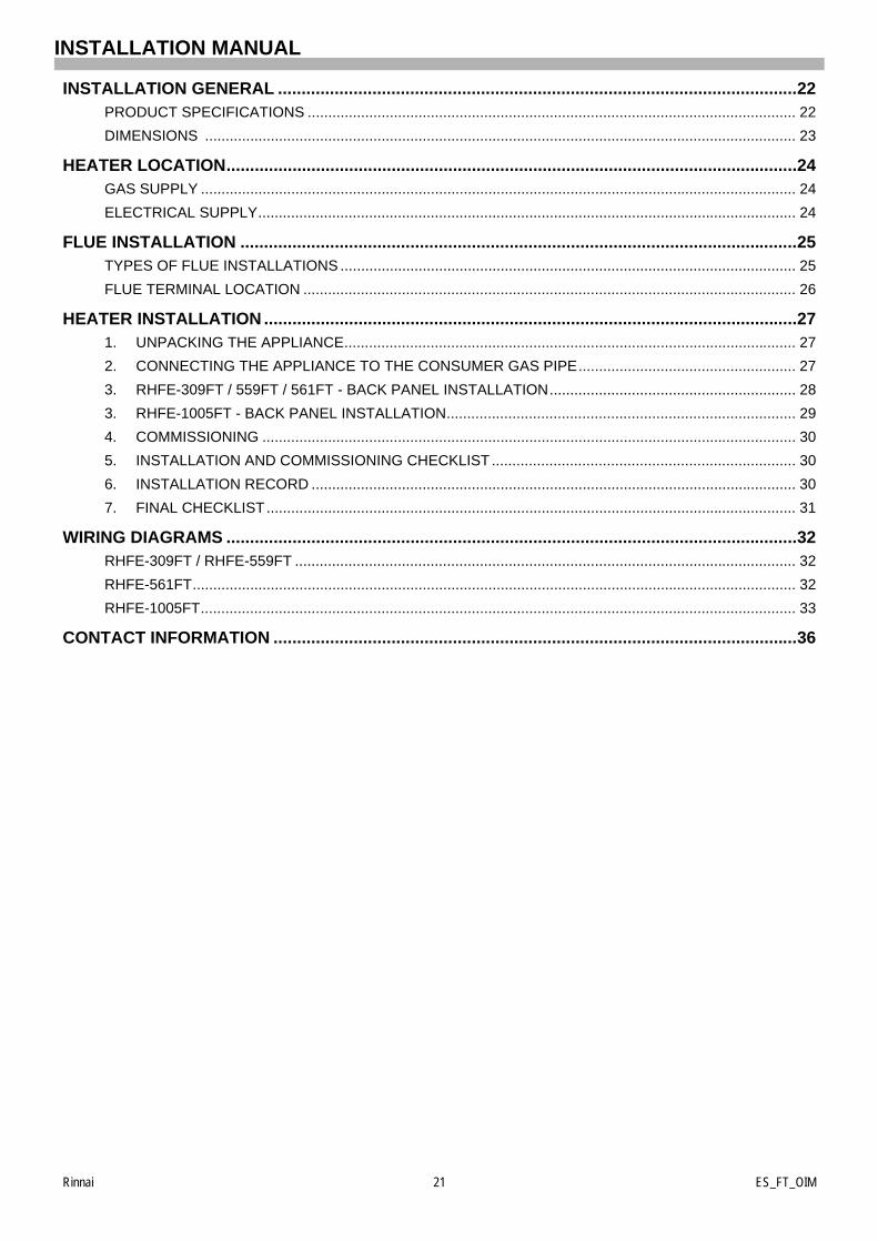
INSTALLATION GENERAL ..............................................................................................................22PRODUCT SPECIFICATIONS ....................................................................................................................... 22
DIMENSIONS ................................................................................................................................................ 23
HEATER LOCATION.........................................................................................................................24GAS SUPPLY ................................................................................................................................................. 24
ELECTRICAL SUPPLY................................................................................................................................... 24
FLUE INSTALLATION ......................................................................................................................25TYPES OF FLUE INSTALLATIONS ............................................................................................................... 25
FLUE TERMINAL LOCATION ........................................................................................................................ 26
HEATER INSTALLATION .................................................................................................................271. UNPACKING THE APPLIANCE.............................................................................................................. 27
2. CONNECTING THE APPLIANCE TO THE CONSUMER GAS PIPE..................................................... 27
3. RHFE-309FT / 559FT / 561FT - BACK PANEL INSTALLATION............................................................ 28
3. RHFE-1005FT - BACK PANEL INSTALLATION..................................................................................... 29
4. COMMISSIONING .................................................................................................................................. 30
5. INSTALLATION AND COMMISSIONING CHECKLIST .......................................................................... 30
6. INSTALLATION RECORD ...................................................................................................................... 30
7. FINAL CHECKLIST................................................................................................................................. 31
WIRING DIAGRAMS .........................................................................................................................32RHFE-309FT / RHFE-559FT .......................................................................................................................... 32
RHFE-561FT................................................................................................................................................... 32
RHFE-1005FT................................................................................................................................................. 33
CONTACT INFORMATION ...............................................................................................................36
INSTALLATION MANUAL

Rinnai 22 ES_FT_OIM
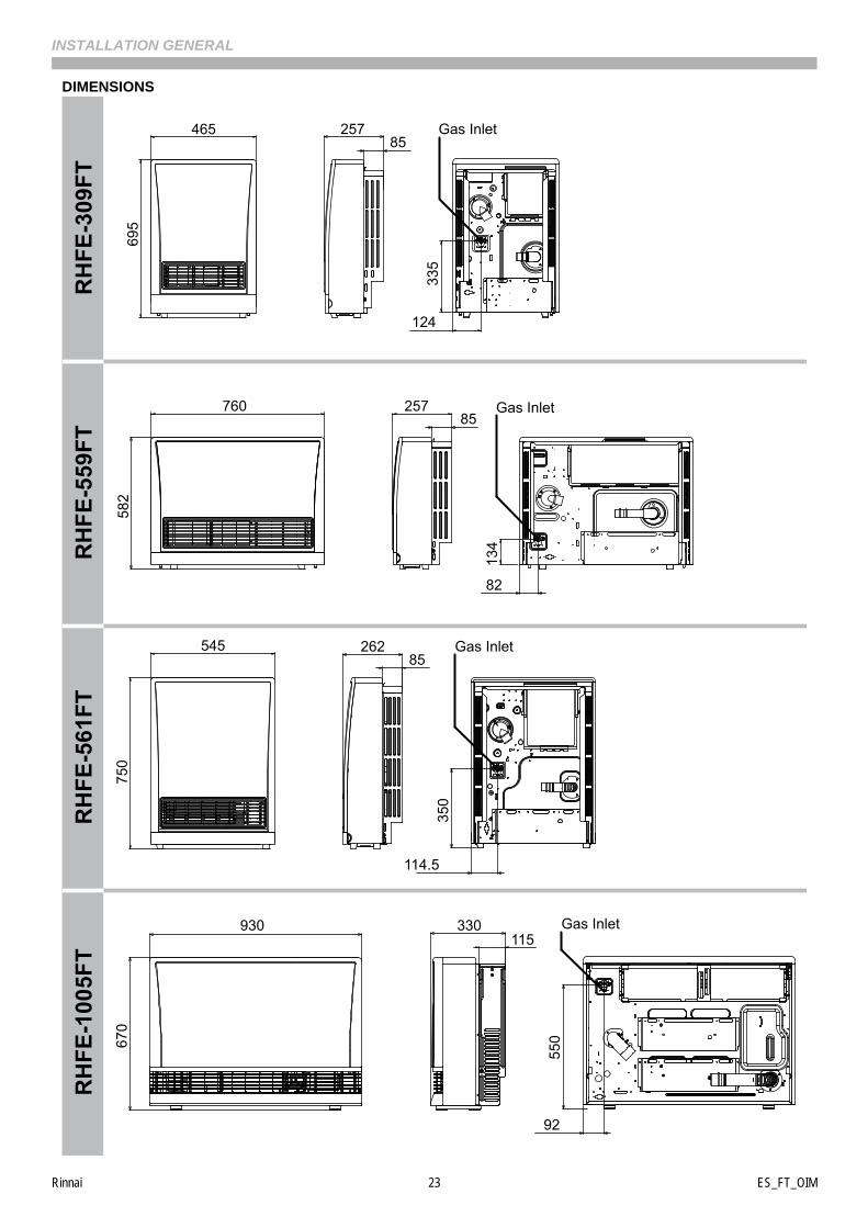
INSTALLATION GENERAL
PRODUCT SPECIFICATIONS
Model RHFE-309FT RHFE-559FT RHFE-561FT RHFE-1005FT
Dimensions(mm)
Height 695 582 750 670
Width 465 760 545 930
Depth 257 257 262 330
Weight (kg) 21 26 25 42
Gas Control Valve Rinnai Electronic Modulating Gas Valve
Burner Fabricated Stainless Steel - Bunsen Burner Type
Injector (mm)
Natural Gas 2x 1.25 Ø 4x 1.25 Ø 4x 1.25 Ø4x 1.50 Ø1x 0.45 Ø
Propane Gas 2x 0.85 Ø 4x 0.82 Ø 4x 0.82 Ø4x 1.00 Ø1x 0.30 Ø
Gas Inlet Thread R ½’ Male (15mm)
Flue SystemFan assisted, twin chamber Co-Axial Flue System, provides air forcombustion to the appliance and allows expulsion of combustion productsto atmosphere. Results in ‘room sealed’ appliance.
Ignition Direct continuous spark electronic ignition
ElectricalSupply
230V / 240V 50Hz with supply lead and 3 pin plugReplace ONLY with Rinnai genuine part
Standby Power Consumption <1W
Convection FanCentrifugal Drum
Type FanCross Flow
Type fanCentrifugal Drum
Type Fan
Temperature Range 16°C to 26°C in 1°C increments
The manufacturer reserves the right to change or modify specifications without notice.
For other appliance specifications refer to appliance data plate.NOTE
Rinnai 23 ES_FT_OIM
INSTALLATION GENERAL
DIMENSIONS
550
92
930115
330
670
350
114.5
545
750
26285
760
582
25785
134
82
46569
5257
85
335
124
Gas Inlet
RH
FE-5
59FT
RH
FE-3
09FT
RH
FE-1
005F
TR
HFE
-561
FT
Gas Inlet
Gas Inlet
Gas Inlet

Rinnai 24 ES_FT_OIM
HEATER LOCATION
When positioning the heater the main variables governing the location are Flueing and Warm Air Distribution.
This heater must not be installed where curtains or other combustible materials could come into contact with it. Insome cases curtains may need restraining.
GAS SUPPLY
The gas supply terminates outside the heater on the back of the appliance.
Locate the gas supply pipe to suit position as per the heater gas inlet. Refer to the dimension drawings on page 23for appliance gas inlet location.
The gap required between the wall and heater body is 85 mm to 205 mm depending on Back Cover Kit is used.
ELECTRICAL SUPPLY
This heater has a power cord with a three pin plug supplied. The cord passes out of the rear of the appliance andcan extend to the left or right of the appliance.
A dedicated 230V / 240V 50Hz earthed 10 Amp power point must be used with this appliance. The power point mustto the left or the right side, it MUST NOT BE above the heater.
Alternatively the appliance can be direct wired if the power supply is to be concealed. The electric isolation switchMUST BE accessible after the appliance has been installed.
For all installations, ONLY Rinnai Energysaver Flue components MUST be used. The RinnaiEnergysaver MUST NOT be flued into ‘natural draft’ flue system or via a chimney.
Consult the Rinnai ‘Energysaver Space Heater Co-Axial flue System installation’ manual includedwith the ‘On Wall’ or ‘Direct’ flue kits for detailed flue installation instructions.
Gas pipe sizing must consider the gas input to this appliance as well as all other gas appliancesin the premises.
The gas meter and regulator must be specified for the total gas rate. Suitable sizing chart such asthe one in AS/NZS 5601 should be used.
PURGING THE GAS SUPPLY: All foreign materials such as filings must be purged from the gassupply, as they may cause the gas control valve to malfunction.
Consult a qualified electrician if direct wiring is required as it must comply with therequirements of AS/NZS 5601 and AS/NZS 3000 and any other relevant local regulations.
WARNING
IMPORTANT
IMPORTANT WARNING
Rinnai 25 ES_FT_OIM
FLUE INSTALLATION
TYPES OF FLUE INSTALLATIONS
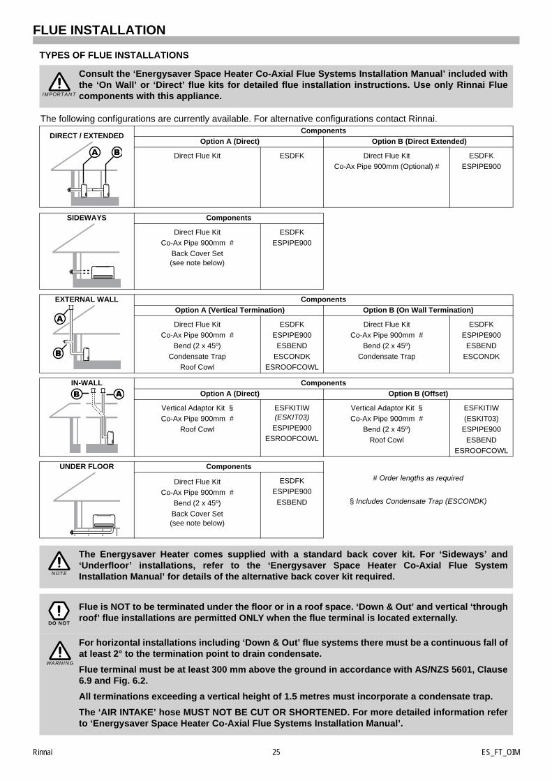
Consult the ‘Energysaver Space Heater Co-Axial Flue Systems Installation Manual’ included withthe ‘On Wall’ or ‘Direct’ flue kits for detailed flue installation instructions. Use only Rinnai Fluecomponents with this appliance.
The following configurations are currently available. For alternative configurations contact Rinnai.Components
DIRECT / EXTENDED Option A (Direct) Option B (Direct Extended)
Direct Flue Kit ESDFK Direct Flue Kit
Co-Ax Pipe 900mm (Optional) #
ESDFK
ESPIPE900
SIDEWAYS Components
Direct Flue Kit
Co-Ax Pipe 900mm #
Back Cover Set (see note below)
ESDFK
ESPIPE900
EXTERNAL WALL Components
Option A (Vertical Termination) Option B (On Wall Termination)
Direct Flue Kit
Co-Ax Pipe 900mm #
Bend (2 x 45º)
Condensate Trap
Roof Cowl
ESDFK
ESPIPE900
ESBEND
ESCONDK
ESROOFCOWL
Direct Flue Kit
Co-Ax Pipe 900mm #
Bend (2 x 45º)
Condensate Trap
ESDFK
ESPIPE900
ESBEND
ESCONDK
IN-WALL Components
Option A (Direct) Option B (Offset)
Vertical Adaptor Kit §
Co-Ax Pipe 900mm #
Roof Cowl
ESFKITIW(ESKIT03)
ESPIPE900
ESROOFCOWL
Vertical Adaptor Kit §
Co-Ax Pipe 900mm #
Bend (2 x 45º)
Roof Cowl
ESFKITIW
(ESKIT03)
ESPIPE900
ESBEND
ESROOFCOWL
UNDER FLOOR Components
Direct Flue Kit
Co-Ax Pipe 900mm #
Bend (2 x 45º)
Back Cover Set(see note below)
ESDFK
ESPIPE900
ESBEND
# Order lengths as required
§ Includes Condensate Trap (ESCONDK)
The Energysaver Heater comes supplied with a standard back cover kit. For ‘Sideways’ and‘Underfloor’ installations, refer to the ‘Energysaver Space Heater Co-Axial Flue SystemInstallation Manual’ for details of the alternative back cover kit required.
Flue is NOT to be terminated under the floor or in a roof space. ‘Down & Out’ and vertical ‘throughroof’ flue installations are permitted ONLY when the flue terminal is located externally.
For horizontal installations including ‘Down & Out’ flue systems there must be a continuous fall ofat least 2° to the termination point to drain condensate.
Flue terminal must be at least 300 mm above the ground in accordance with AS/NZS 5601, Clause6.9 and Fig. 6.2.
All terminations exceeding a vertical height of 1.5 metres must incorporate a condensate trap.
The ‘AIR INTAKE’ hose MUST NOT BE CUT OR SHORTENED. For more detailed information referto ‘Energysaver Space Heater Co-Axial Flue Systems Installation Manual’.
IMPORTANT
NOTE
DO NOT
WARNING
Rinnai 26 ES_FT_OIM
FLUE INSTALLATION
FLUE TERMINAL LOCATION
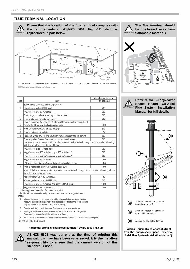
Ensue that the location of the flue terminal complies withthe requirements of AS/NZS 5601, Fig. 6.2 which isreproduced in part below.
The flue terminal shouldbe positioned away fromflammable materials.
Horizontal terminal clearances (Extract AS/NZS 5601 Fig. 6.2)
Refer to the ‘EnergysaverSpace Heater Co-AxialFlue System InstallationManual’ for full details
‘Vertical Terminal clearances (Extract from the ‘Energysaver Space Heater Co-Axial Flue System Installation Manual’)AS/NZS 5601 was current at the time of printing this
manual, but may have been superseded. It is the installersresponsibility to ensure that the current version of thisstandard is used.
WARNING WARNING
Flue terminal Fan assisted flue appliance only Gas meter Electricity meter or fuse box Mechanical air inlet
Fan assisted
• Appliances up to 50 MJ/h input 200• Appliances over 50 MJ/h input 300
b From the ground, above a balcony or other surface * 300c Front a return wall or external corner * 300
dFrom a gas meter (M) (see 5.11.5.9 for vent terminal location of regulator )(see Table 6.6 for New Zealand requirements) 1000
e From an electricity meter or fuse box (P) † 500f From a drain pipe or soil pipe 75g Horizontally from any building structure* = or obstruction facing a terminal 500h From any other flue terminal , cowl, or combustion air intake † 300
• Appliances up to 150 MJ/h input * 300• Appliances over 150 MJ/h input up to 200 MJ/h input * 300• Appliances over 200 MJ/h input up to 250 MJ/h input * 500• Appliances over 250 MJ/h input * 1500• All fan-assisted flue appliances , in the direction of discharge 1500
k From a mechanical air inlet, including a spa blower 1000
• Space heaters up to 50 MJ/h input 150• Other appliances up to 50 MJ/h input 500• Appliances over 50 MJ/h input and up to 150 MJ/h input 1000• Appliances over 150 MJ/h input 1500
1 Where dimensions c, j or k cannot be achieved an equivalent horizontal distance measured diagonally from the nearest discharge point of the terminal to the opening may be deemed by the Technical Regulator to comply.
2 See Clause 6.9.4 for restrictions on a flue terminal under a covered area.3 See Figure J3 for clearances required from a flue terminal to an LP Gas cylinder.
A flue terminal is considered to be a source of ignition.4
Ref. Item
a
Min. clearances (mm)
Below eaves, balconies and other projections:
j
Horizontally from an openable window, door, non-mechanical air inlet, or any other opening into a building with the exception of sub-floor ventilation:
Vertically below an openable window, non-mechanical air inlet, or any other opening into a building with the exception of sub-floor ventilation:
NOTES:† - Prohibited area below electricity meter or fuse box extends to ground level.
EXTRACT OF FIGURE 6.2 (in-part)
* - unless appliance is certified for closer installation
For appliance s not addressed above acceptance should be obtained from the Technical Regulator.
n
IMPORTANT
IMPORTANT
Rinnai 27 ES_FT_OIM
HEATER INSTALLATION
1. UNPACKING THE APPLIANCE
The heater is supplied in one carton containing; Heater, Standard Rear Cover Set and Bolt Pack (refer to the“CARTON CONTENTS / ITEM CHECKLIST” on page 4 for a full list of the items packed with each heater model).
Remove all packaging materials and check for damage. If any damage is evident DO NOT install or operate thisappliance and contact your supplier for advice.
Before installing the heater, check it is labelled for the correct gas type, (refer to the data label at the rear of theheater). Refer to the local gas authority for confirmation of gas type if you are in doubt.
2. CONNECTING THE APPLIANCE TO THE CONSUMER GAS PIPE
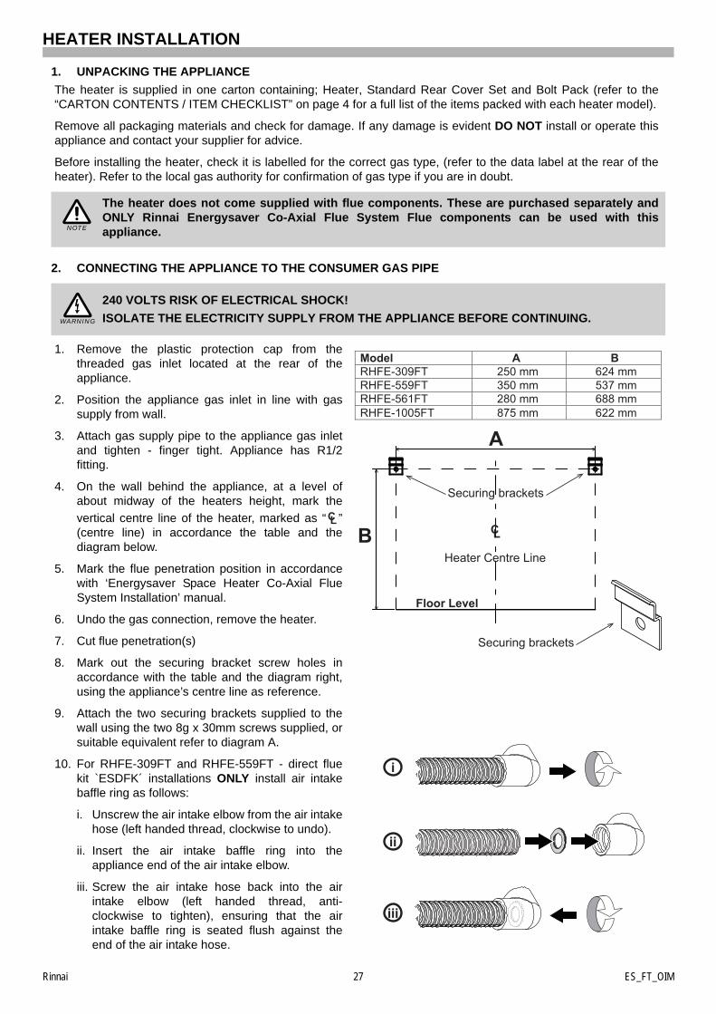
1. Remove the plastic protection cap from thethreaded gas inlet located at the rear of theappliance.
2. Position the appliance gas inlet in line with gassupply from wall.
3. Attach gas supply pipe to the appliance gas inletand tighten - finger tight. Appliance has R1/2fitting.
4. On the wall behind the appliance, at a level ofabout midway of the heaters height, mark the
vertical centre line of the heater, marked as “ ”(centre line) in accordance the table and thediagram below.
5. Mark the flue penetration position in accordancewith ‘Energysaver Space Heater Co-Axial FlueSystem Installation’ manual.
6. Undo the gas connection, remove the heater.
7. Cut flue penetration(s)
8. Mark out the securing bracket screw holes inaccordance with the table and the diagram right,using the appliance’s centre line as reference.
9. Attach the two securing brackets supplied to thewall using the two 8g x 30mm screws supplied, orsuitable equivalent refer to diagram A.
10. For RHFE-309FT and RHFE-559FT - direct fluekit `ESDFK´ installations ONLY install air intakebaffle ring as follows:
i. Unscrew the air intake elbow from the air intakehose (left handed thread, clockwise to undo).
ii. Insert the air intake baffle ring into theappliance end of the air intake elbow.
iii. Screw the air intake hose back into the airintake elbow (left handed thread, anti-clockwise to tighten), ensuring that the airintake baffle ring is seated flush against theend of the air intake hose.
The heater does not come supplied with flue components. These are purchased separately andONLY Rinnai Energysaver Co-Axial Flue System Flue components can be used with thisappliance.
240 VOLTS RISK OF ELECTRICAL SHOCK!
ISOLATE THE ELECTRICITY SUPPLY FROM THE APPLIANCE BEFORE CONTINUING.
NOTE
WARNING
A
B CL
Floor Level
Heater Centre Line
Securing brackets
Securing brackets
i
ii
iii
Model A B RHFE-309FT 250 mm 624 mm RHFE-559FT 350 mm 537 mm RHFE-561FT 280 mm 688 mm RHFE-1005FT / FDT 875 mm 622 mm
CL
Rinnai 28 ES_FT_OIM
HEATER INSTALLATION
11. Install flue system in accordance with ‘Energysaver Space Heater Co-Axial Flue System Installation manual’which is provided with the flue kit.
12. Return the heater to the final position.
13. Connect flue in accordance with ‘Energysaver Space Heater, Co-Axial Flue System Installation Manual’.
14. Connect gas supply line and fully tighten connection.
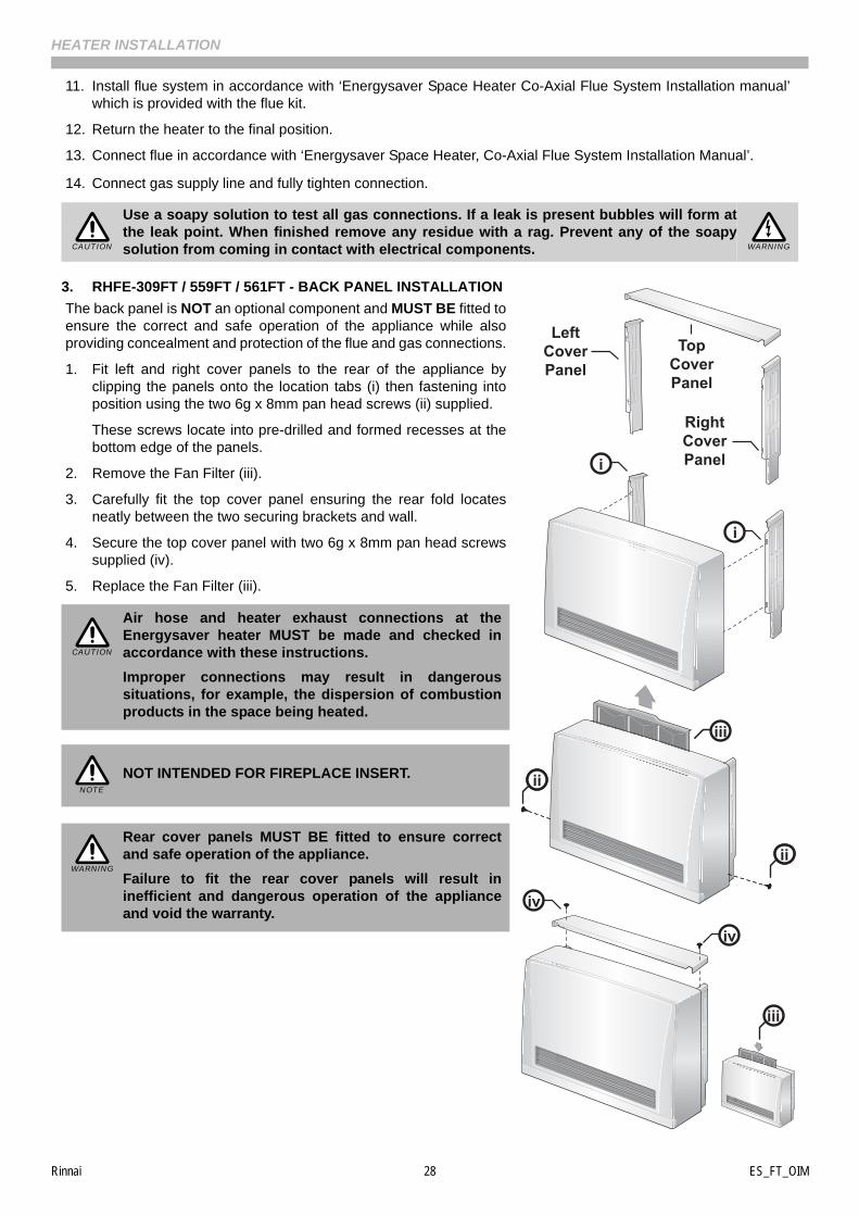
3. RHFE-309FT / 559FT / 561FT - BACK PANEL INSTALLATION
The back panel is NOT an optional component and MUST BE fitted toensure the correct and safe operation of the appliance while alsoproviding concealment and protection of the flue and gas connections.
1. Fit left and right cover panels to the rear of the appliance byclipping the panels onto the location tabs (i) then fastening intoposition using the two 6g x 8mm pan head screws (ii) supplied.
These screws locate into pre-drilled and formed recesses at thebottom edge of the panels.
2. Remove the Fan Filter (iii).
3. Carefully fit the top cover panel ensuring the rear fold locatesneatly between the two securing brackets and wall.
4. Secure the top cover panel with two 6g x 8mm pan head screwssupplied (iv).
5. Replace the Fan Filter (iii).
Use a soapy solution to test all gas connections. If a leak is present bubbles will form atthe leak point. When finished remove any residue with a rag. Prevent any of the soapysolution from coming in contact with electrical components.
Air hose and heater exhaust connections at theEnergysaver heater MUST be made and checked inaccordance with these instructions.
Improper connections may result in dangeroussituations, for example, the dispersion of combustionproducts in the space being heated.
NOT INTENDED FOR FIREPLACE INSERT.
Rear cover panels MUST BE fitted to ensure correctand safe operation of the appliance.
Failure to fit the rear cover panels will result ininefficient and dangerous operation of the applianceand void the warranty.
CAUTION WARNING
i
iv
iv
ii
ii
iv
iv
TopCoverPanel
RightCoverPanel
LeftCoverPanel
iii
iii
i
CAUTION
NOTE
WARNING
Rinnai 29 ES_FT_OIM
HEATER INSTALLATION
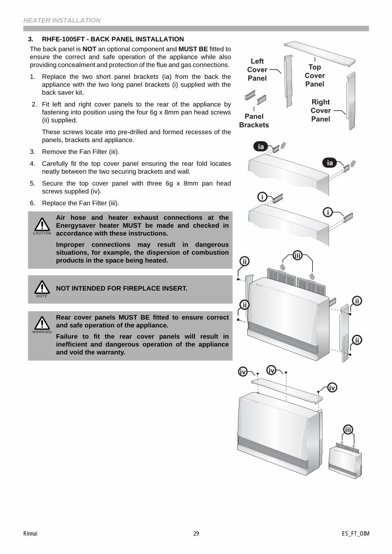
3. RHFE-1005FT - BACK PANEL INSTALLATION
The back panel is NOT an optional component and MUST BE fitted toensure the correct and safe operation of the appliance while alsoproviding concealment and protection of the flue and gas connections.
1. Replace the two short panel brackets (ia) from the back theappliance with the two long panel brackets (i) supplied with theback saver kit.
2. Fit left and right cover panels to the rear of the appliance byfastening into position using the four 6g x 8mm pan head screws(ii) supplied.
These screws locate into pre-drilled and formed recesses of thepanels, brackets and appliance.
3. Remove the Fan Filter (iii).
4. Carefully fit the top cover panel ensuring the rear fold locatesneatly between the two securing brackets and wall.
5. Secure the top cover panel with three 6g x 8mm pan headscrews supplied (iv).
6. Replace the Fan Filter (iii).
Air hose and heater exhaust connections at theEnergysaver heater MUST be made and checked inaccordance with these instructions.
Improper connections may result in dangeroussituations, for example, the dispersion of combustionproducts in the space being heated.
NOT INTENDED FOR FIREPLACE INSERT.
Rear cover panels MUST BE fitted to ensure correctand safe operation of the appliance.
Failure to fit the rear cover panels will result ininefficient and dangerous operation of the applianceand void the warranty.
iv
iv
TopCoverPanel
RightCoverPanel
LeftCoverPanel
ivii
ii
ia
ia
PanelBrackets
i
i
iv
ivii
iiiii
iii
CAUTION
NOTE
WARNING
Rinnai 30 ES_FT_OIM
HEATER INSTALLATION
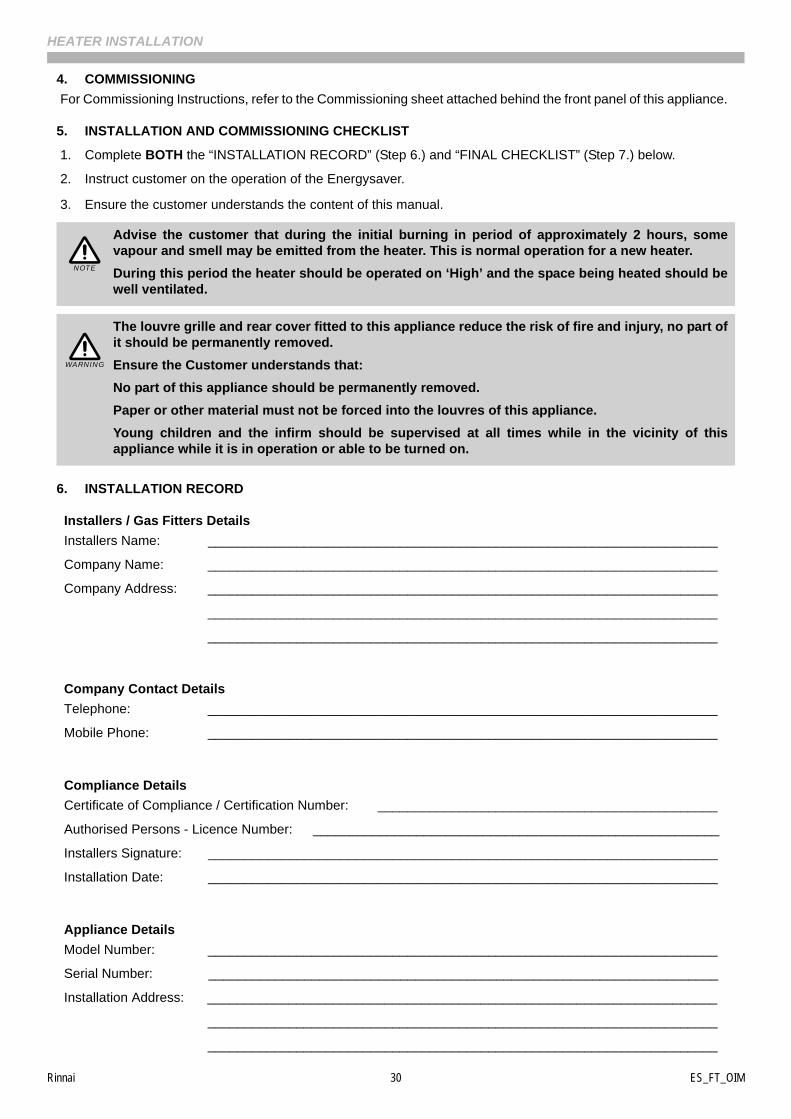
4. COMMISSIONING
For Commissioning Instructions, refer to the Commissioning sheet attached behind the front panel of this appliance.
5. INSTALLATION AND COMMISSIONING CHECKLIST
1. Complete BOTH the “INSTALLATION RECORD” (Step 6.) and “FINAL CHECKLIST” (Step 7.) below.
2. Instruct customer on the operation of the Energysaver.
3. Ensure the customer understands the content of this manual.
6. INSTALLATION RECORD
Installers / Gas Fitters Details
Installers Name: _____________________________________________________________________
Company Name: _____________________________________________________________________
Company Address: _____________________________________________________________________
_____________________________________________________________________
_____________________________________________________________________
Company Contact Details
Telephone: _____________________________________________________________________
Mobile Phone: _____________________________________________________________________
Compliance Details
Certificate of Compliance / Certification Number: ______________________________________________
Authorised Persons - Licence Number: _______________________________________________________
Installers Signature: _____________________________________________________________________
Installation Date: _____________________________________________________________________
Appliance Details
Model Number: _____________________________________________________________________
Serial Number: _____________________________________________________________________
Installation Address: _____________________________________________________________________
_____________________________________________________________________
_____________________________________________________________________
Advise the customer that during the initial burning in period of approximately 2 hours, somevapour and smell may be emitted from the heater. This is normal operation for a new heater.
During this period the heater should be operated on ‘High’ and the space being heated should bewell ventilated.
The louvre grille and rear cover fitted to this appliance reduce the risk of fire and injury, no part ofit should be permanently removed.
Ensure the Customer understands that:
No part of this appliance should be permanently removed.
Paper or other material must not be forced into the louvres of this appliance.
Young children and the infirm should be supervised at all times while in the vicinity of thisappliance while it is in operation or able to be turned on.
NOTE
WARNING
Rinnai 31 ES_FT_OIM
HEATER INSTALLATION
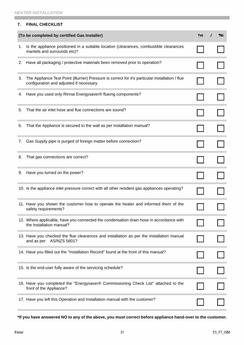
7. FINAL CHECKLIST
*If you have answered NO to any of the above, you must correct before appliance hand-over to the customer.
(To be completed by certified Gas Installer) Yes / *No
1. Is the appliance positioned in a suitable location (clearances, combustible clearancesmantels and surrounds etc)?
2. Have all packaging / protective materials been removed prior to operation?
3. The Appliance Test Point (Burner) Pressure is correct for it's particular installation / flueconfiguration and adjusted if necessary.
4. Have you used only Rinnai Energysaver® flueing components?
5. That the air inlet hose and flue connections are sound?
6. That the Appliance is secured to the wall as per Installation manual?
7. Gas Supply pipe is purged of foreign matter before connection?
8. That gas connections are correct?
9. Have you turned on the power?
10. Is the appliance inlet pressure correct with all other resident gas appliances operating?
11. Have you shown the customer how to operate the heater and informed them of thesafety requirements?
12. Where applicable, have you connected the condensation drain hose in accordance withthe Installation manual?
13. Have you checked the flue clearances and installation as per the Installation manualand as per AS/NZS 5601?
14. Have you filled out the "Installation Record" found at the front of this manual?
15. Is the end-user fully aware of the servicing schedule?
16. Have you completed the "Energysaver® Commissioning Check List" attached to thefront of the Appliance?
17. Have you left this Operation and Installation manual with the customer?
Rinnai 32 ES_FT_OIM
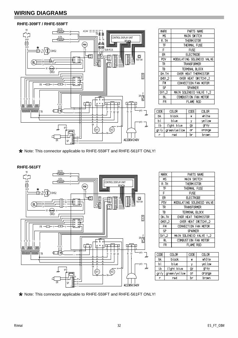
WIRING DIAGRAMS
RHFE-309FT / RHFE-559FT
Note: This connector applicable to RHFE-559FT and RHFE-561FT ONLY!
RHFE-561FT
Note: This connector applicable to RHFE-559FT and RHFE-561FT ONLY!
CONTROL DISPLAY UNIT
rr
r
bl
WW
OH.TH
R.THyy
TEST SW3
1
TF
OHS1
12
1
yy
1
8
wER SP
gr/y
gyorblr
SV1 SV2
gr/y
3AF
FR
MS
10
OHS2
bl
w w
rbk
rbkyw
brlbgy gyww
3
1
w
gr/y
TR
bl
2 1 4 1 3
1
8
1
4
3
1
4
3
6
6
1 4
1
5
8 4
1
wybk
ygyor
ry rblbkbrbr
ww
w
wbl
blbl
bk
1
3
SUB-P.C.B.wbl
bk
TBAC24V
r
bk
CONTROL DISPLAY UNIT
rr
r
bl
WW
OH.TH
R.THyy
TEST SW31
TF
OHS1
12
1
yy
9
1
wER SP
gr/y
gyorblr
SV1 SV2
gr/y
3AF
FR
MS
10
OHS2
bl
w w
rbk
ybkrw
brlbgy gyww
31
w
gr/y
TR
bl
2 1 4 1 3
1
18
1
4
3
1
4
3
6
6
1 4
1
5
8 4
1
wybk
ygyor
ry rblbkbrbr
ww
w
wbl
blblw
rbky
bk
Rinnai 33 ES_FT_OIM
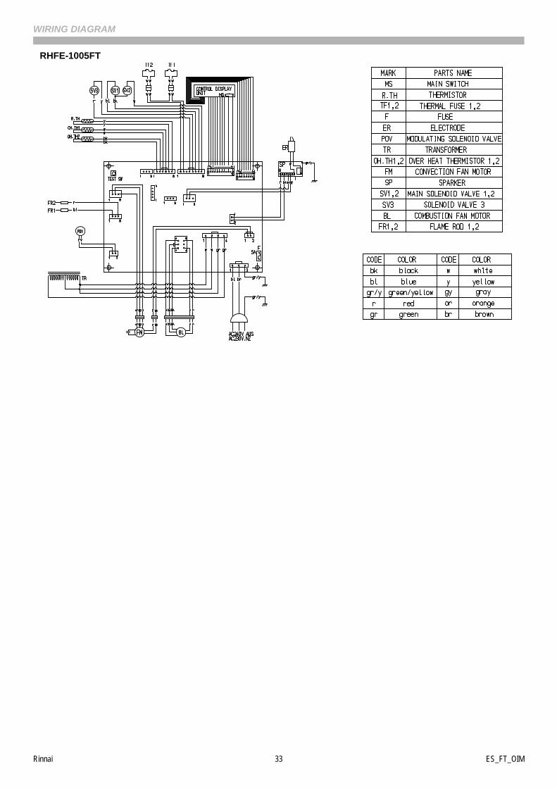
WIRING DIAGRAM
RHFE-1005FT

Rinnai 34 ES_FT_OIM
INSTALLATION NOTES

Rinnai 35 ES_FT_OIM
This page is intentionally blank

Rinnai 36 ES_FT_OIM 13_004 Issue 5 24/11/14
Australia Pty. Ltd. ABN 74 005 138 769
Rinnai has a Service and Spare Parts network with personnel who are fully trained and equipped to give the best service on your Rinnai appliance. If your appliance requires service, please call our National Help Line. Rinnai recommends that this appliance be serviced every 2 years.
Head Office 100 Atlantic Drive,Keysborough VIC 3173
P.O. Box 460Braeside, Victoria 3195
Internet: www.rinnai.com.au E-mail: [email protected]
National Help LineTel: 1300 555 545* Fax: 1300 555 655**Cost of a local call higher from mobile or public phones.
RHF559-1152x06(00)
102808
CONTACT INFORMATION