Embed Size (px)
Citation preview
Operation and Technical Manual
Model 111W Hyperthermia Units
Cincinnati Sub-Zero Products, Inc. 12011 Mosteller Road Cincinnati, Ohio 45241, U.S.A. www.cszmedical.com
In Europe: CEpartner4U Esdoornlaan 13, 3951 DB Maarn.
The Netherlands
I
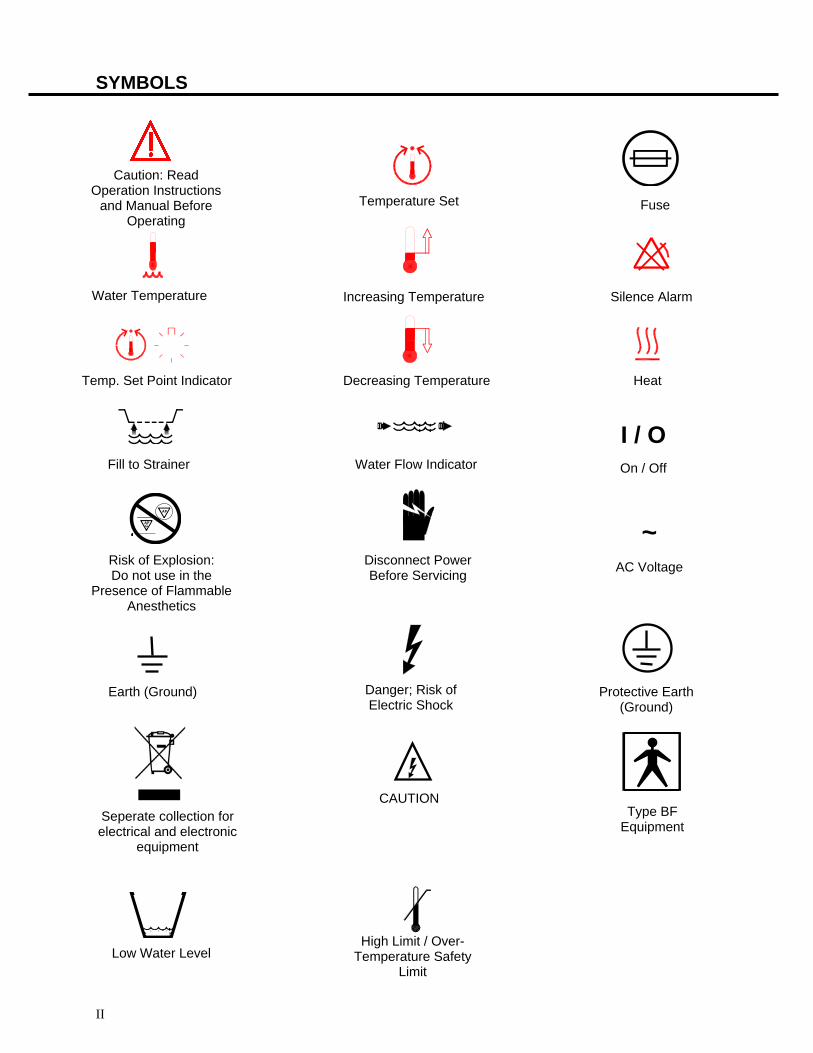
SYMBOLS
Fill to Strainer
Temperature Set
Water Temperature
Temp. Set Point Indicator
Risk of Explosion: Do not use in the
Presence of Flammable Anesthetics
Danger; Risk of Electric Shock
Increasing Temperature
Decreasing Temperature
Disconnect Power Before Servicing
Water Flow Indicator
Fuse
Silence Alarm
Caution: Read Operation Instructions
and Manual Before Operating
Type BF Equipment
I / O
On / Off
~
AC Voltage
Heat
Earth (Ground)
CAUTION
Protective Earth (Ground)
Seperate collection for electrical and electronic
equipment
High Limit / Over-Temperature Safety
Limit Low Water Level
II
NORM-O-TEMP®
MODEL 111W OPERATION & TECHNICAL MANUAL
The operator must read and understand the Operation/Technical Manual in its entirety prior to operating the equipment. This document contains proprietary information and such information that may not be disclosed to others for any purpose or used for manufacturing purposes without written permission from Cincinnati Sub-Zero Products, Inc., 12011 Mosteller Road, Cincinnati, Ohio 45241-1528, Telephone: (513) 772-8810. Cincinnati Sub-Zero Products, Inc., reserves the right to make equipment changes and improvements which may not be reflected in this manual. This document may not be reproduced in whole or in part without written permission from Cincinnati Sub-Zero Products, Inc.
Manual 56203 Rev. AB ECN: M104-4115
2011-04
III
START UP INSTRUCTIONS: INSERT
When turning ON your Norm-O-Temp, the unit will go through a short diagnostic sequence. The display will read “HE” indicating the heating of the internal water. When the internal water temperature reaches 65°F/18°C, the actual internal water temperature will be displayed. If at the end of the three (3) minute sequence the water has not reached an internal temperature of 65°F/18°C the display will read “ERR”. If this occurs turn power OFF and then back ON to repeat diagnostic check. If after second diagnostic check “ERR” is still displayed, remove from service. Please call 1-800-989-7373 for CSZ Medical Technical Service.
IV
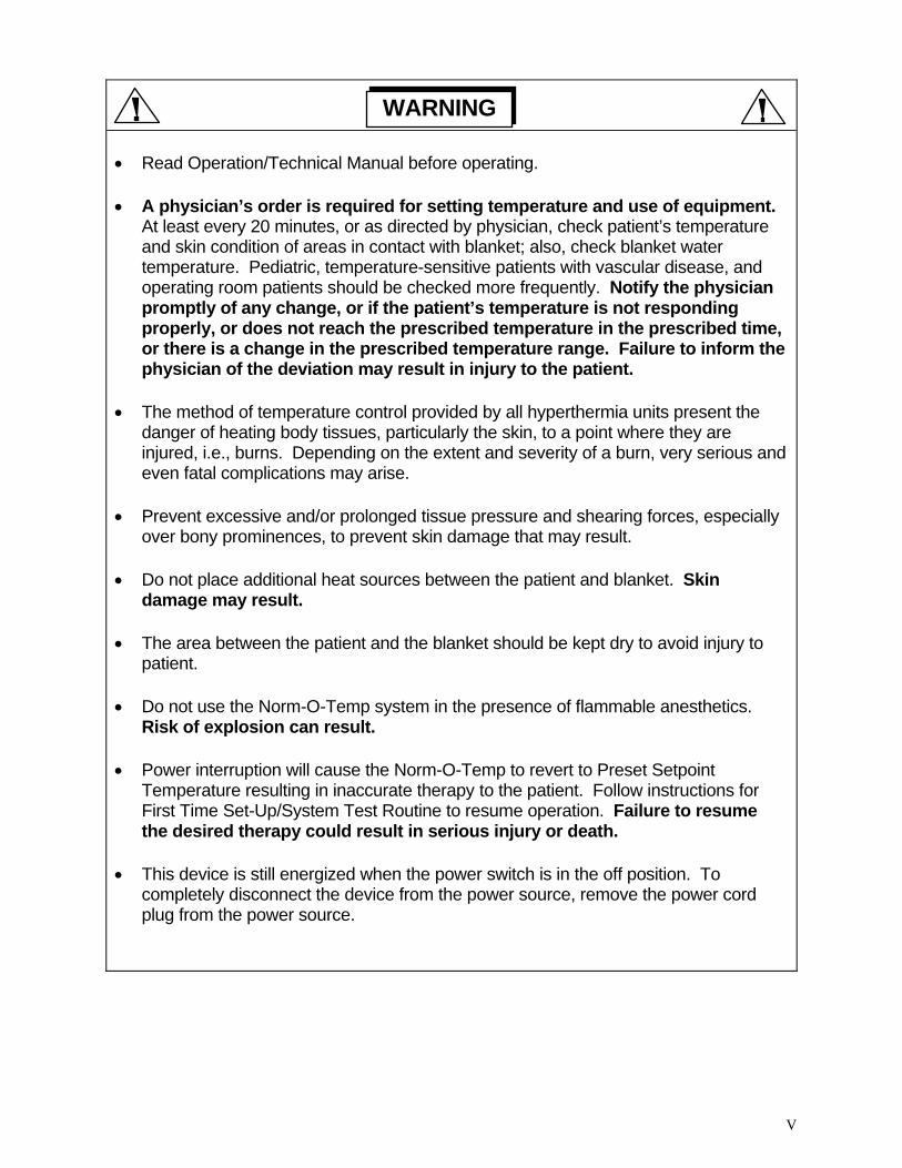
Read Operation/Technical Manual before operating.
A physician’s order is required for setting temperature and use of equipment. At least every 20 minutes, or as directed by physician, check patient’s temperature and skin condition of areas in contact with blanket; also, check blanket water temperature. Pediatric, temperature-sensitive patients with vascular disease, and operating room patients should be checked more frequently. Notify the physician promptly of any change, or if the patient’s temperature is not responding properly, or does not reach the prescribed temperature in the prescribed time, or there is a change in the prescribed temperature range. Failure to inform the physician of the deviation may result in injury to the patient.
The method of temperature control provided by all hyperthermia units present the danger of heating body tissues, particularly the skin, to a point where they are injured, i.e., burns. Depending on the extent and severity of a burn, very serious and even fatal complications may arise.
Prevent excessive and/or prolonged tissue pressure and shearing forces, especially over bony prominences, to prevent skin damage that may result.
Do not place additional heat sources between the patient and blanket. Skin damage may result.
The area between the patient and the blanket should be kept dry to avoid injury to patient.
Do not use the Norm-O-Temp system in the presence of flammable anesthetics. Risk of explosion can result.
Power interruption will cause the Norm-O-Temp to revert to Preset Setpoint Temperature resulting in inaccurate therapy to the patient. Follow instructions for First Time Set-Up/System Test Routine to resume operation. Failure to resume the desired therapy could result in serious injury or death.
This device is still energized when the power switch is in the off position. To completely disconnect the device from the power source, remove the power cord plug from the power source.
WARNING
V
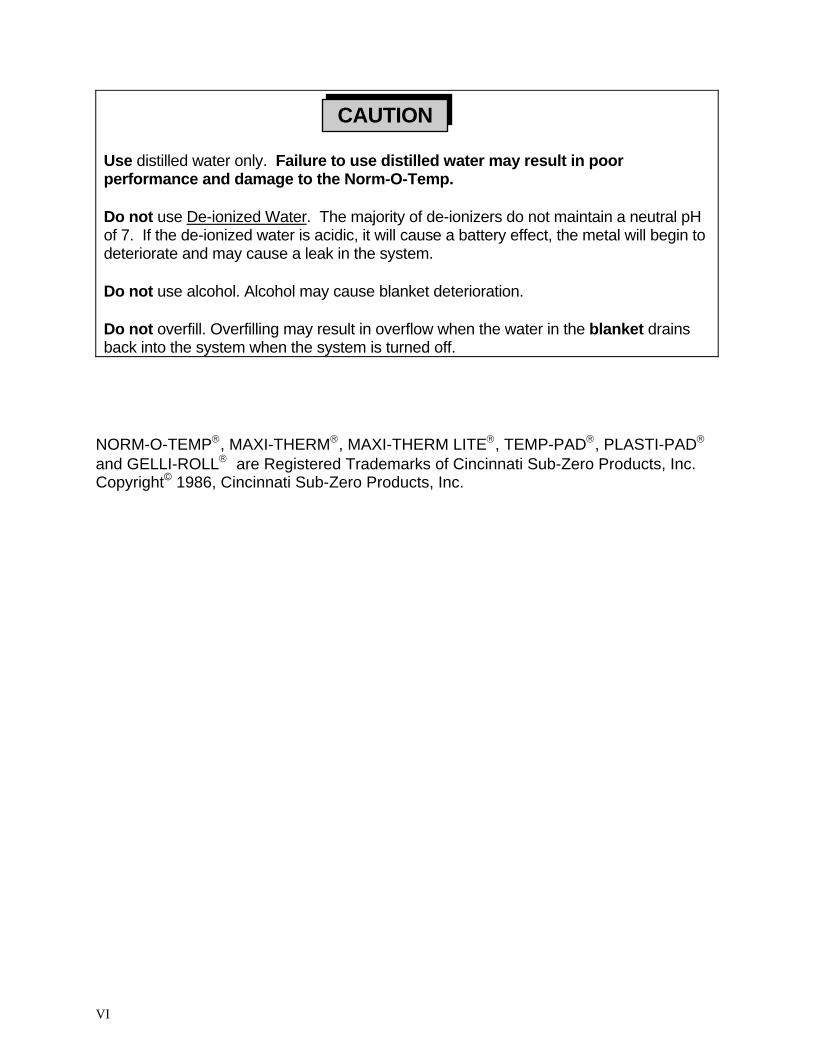
Use distilled water only. Failure to use distilled water may result in poor performance and damage to the Norm-O-Temp.
Do not use De-ionized Water. The majority of de-ionizers do not maintain a neutral pH of 7. If the de-ionized water is acidic, it will cause a battery effect, the metal will begin to deteriorate and may cause a leak in the system.
Do not use alcohol. Alcohol may cause blanket deterioration.
Do not overfill. Overfilling may result in overflow when the water in the blanket drains back into the system when the system is turned off.
CAUTION
NORM-O-TEMP, MAXI-THERM, MAXI-THERM LITE, TEMP-PAD, PLASTI-PAD and GELLI-ROLL are Registered Trademarks of Cincinnati Sub-Zero Products, Inc. Copyright© 1986, Cincinnati Sub-Zero Products, Inc.
VI
NORM-O-TEMP MODEL 111W TABLE OF CONTENTS
Page No. TECHNICAL HELP ...................................................................................................................................................1
BEFORE YOU CALL FOR SERVICE... ......................................................................................................................1 IN-WARRANTY REPAIR AND PARTS .....................................................................................................................1
RECEIVING INSPECTION ......................................................................................................................................1
IMPORTANT SAFETY INFORMATION ...............................................................................................................1
SECTION 1. ...........................................................................................................................3 INTRODUCTION
1-0. .............................................................................................................3 GENERAL SAFETY PRECAUTIONS1-1. ............................................................................................3 GENERAL DESCRIPTION OF THIS MANUAL1-2. ..................................................................3 GENERAL DESCRIPTION OF THE NORM-O-TEMP SYSTEM1-3. ............................................................................................................................4 CLINICAL APPLICATIONS1-4. ..................................................................................4 PHYSICAL DESCRIPTION OF THE NORM-O-TEMP
1-4.1. .................................................................................................4 EXTERNAL FEATURES - FRONT VIEW1-4.2. ...........................................................................................6 EXTERNAL FEATURES - LEFT SIDE VIEW1-4.3. ....................................................................................................8 EXTERNAL FEATURES - REAR VIEW1-4.4. .........................................................................................9 EXTERNAL FEATURES - RIGHT SIDE VIEW1-4.5. .......................................................................................................................9 TOP VIEW DESCRIPTION1-4.5. .....................................................................................................................10 TOP VIEW DESCRIPTION
1-5. ..........................................................................................................................12 REQUIRED ACCESSORIES1-6. ..........................................................................12 FUNCTIONAL DESCRIPTION OF THE NORM-O-TEMP
1-6.1. .................................................................................................................................12 HEATING SYSTEM1-6.2. ........................................................................................................................13 CIRCULATING SYSTEM1-6.3 .....................................................................................13 TEMPERATURE SAFETY CONTROL SYSTEM
1-7. ..............................................................................................14 SPECIFICATIONS OF THE NORM-O-TEMP
SECTION 2. GENERAL PREPARATION OF THE UNIT................................................................................17
2-1. ...........................................................................................................................................17 INTRODUCTION2-2. .....................................................................................................................17 UNPACKING THE SHIPMENT2-3. ........................................................................................17 FIRST TIME SET-UP/SYSTEM TEST ROUTINE
2-3.1. ...........................................................................17 INSPECTING AND ARRANGING THE EQUIPMENT2-3.2. ..........................................................................................18 COMPLETING A SYSTEM TEST ROUTINE
2-4. ......................................................................................21 UNIT AND PATIENT RELATED PRECAUTIONS2-5. ......................................................................................22 PATIENT PREPARATION AND BEDSIDE CARE
SECTION 3. OPERATING THE NORM-O-TEMP............................................................................................24
3-1. ...........................................................................................................................................24 INTRODUCTION3-2. .............................................................................................................24 ARRANGING THE COMPONENTS3-3. .............................................................................................................26 OPERATING THE NORM-O-TEMP3-4. ...................................................................................26 CONCLUDING THE USE OF THE NORM-O-TEMP
SECTION 4. ......................................................27 GENERAL MAINTENANCE OF THE NORM-O-TEMP
4-1. ...........................................................................................................................................27 INTRODUCTION4-2. ........................................................................................31 MAINTENANCE OF THE WATER RESERVOIR
4-2.1. ................................................................................................................31 DRAINING THE RESERVOIR4-2.2. .......................................................................................................32 REPLENISHING THE RESERVOIR
4-3 ................................................................................................32 MAINTENANCE OF THE WATER FILTER4-4 ...................................................................33 MAINTENANCE OF THE WATER CIRCULATING SYSTEM4-5 ............................................................................35 MAINTENANCE OF THE NORM-O-TEMP EXTERIOR4-6. ...............................................................................35 MAINTENANCE OF HYPER-HYPOTHERMIA PADS
4-6.1 .......................................................................................................35 PLASTIPAD REUSABLE BLANKET
VII
4-6.2 ......................36 MAXI-THERM, MAXI-THERM LITE AND TEMP-PAD SINGLE-PATIENT USE PADS
SECTION 5. ...........................................................37 FIELD REPAIR/SERVICE OF THE NORM-O-TEMP
5-1. ...........................................................................................................................................37 INTRODUCTION5-2. ........................................................................................................................38 ACCESS TO THE INTERIOR
5-2.1. ...................................................................................................38 REMOVING THE TOP OF THE UNIT5-2.2. .................................................................................39 REPLACE/REINSTALL THE TOP OF THE UNIT5-2.3. ......................................................................39 REMOVING THE THREE SIDED ENCLOSURE PANEL5-2.4. ....................................................39 REPLACE/REINSTALL THE THREE-SIDED ENCLOSURE PANEL
5-3. .............................................................................................................39 REPLACEMENT OF THE HEATER5-4. ................................................................................................40 REPLACEMENT OF THE PUMP HOUSING5-5. ...................................................................................................41 REPLACEMENT OF THE PUMP MOTOR5-6. ...........................................................................42 REPLACEMENT OF THE WATER FILTER ASSEMBLY5-7. .................................................................43 REPLACEMENT OF THE WATER TEMPERATURE SENSOR5.8 .......................................................................................43 REPLACEMENT OF THE WATER MANIFOLDS
5-8.1 .............................................................................................................................43 OUTLET MANIFOLD5-8.2 .............................................................................................................................44 RETURN MANIFOLD
5-9. ................................45 REPLACEMENT OF THE INDEPENDENT HIGH LIMIT SAFETY THERMOSTAT5-10. ..............................46 CALIBRATION OF THE INDEPENDENT HIGH LIMIT SAFETY THERMOSTAT
5.11 ...........................................................................................................................................47 HI-LIMIT TEST5-12. ......................47 REPLACEMENT OR CLEANING OF THE WATER FLOW INDICATOR ASSEMBLY5-13. ...........................................................................................48 REPLACEMENT OF THE POWER SWITCH5-14. ................................................................................49 REPLACEMENT OF THE SOLID STATE RELAYS5-15. ........................................................49 REPLACEMENT OF THE WATER LEVEL SENSOR ASSEMBLY5-16. ............................................................................................50 REPLACEMENT OF THE TRANSFORMER5-17. ............50 REPLACEMENT OF THE MICROPROCESSOR BOARD AND/OR THE CONTROL PANEL5-18 .............................................................................................................................51 ELECTRICAL SAFETY
5-18.1. ........................................................................................................................52 GROUND INTEGRITY5-18.2. .........................................................................................................................52 LEAKAGE CURRENT
SECTION 6. ..................................................................................................53 TROUBLESHOOTING GUIDE
SECTION 7. .............................................................................................................58 PARTS INFORMATION
7-1. ...........................................................................................................................................58 INTRODUCTION7-2. .....................................................................58 ORDERING INFORMATION FOR REPLACEMENT PARTS7-3. .......................................................................59 RECOMMENDED REPLACEMENT PARTS INVENTORY7.4 ...............................................................................................59 RETURNING PARTS UNDER WARRANTY7-5. ..........................................................................................................................................59 SHIPPING PARTS
ACCESSORIES - PADS ...........................................................................................................................................68
TEMPERATURE PROBES .....................................................................................................................................68
VIII
LIST OF ILLUSTRATIONS Page No. Figure 1-4.1 External Features-Front View ............................................4 Figure 1-4.2 External Features-Left Side View.......................................6 Figure 1-4.3 External Features-Rear View .............................................7 Figure 1-4.4 External Features-Right Side View ....................................8 Figure 1-4.5 NORM-O-TEMP Top View ............... ...............................10 Figure 1-6. Temperature Safety Limits ...............................................13 Figure 1-7. NORM-O-TEMP Specifications ........................................14 Figure 4-1. Scheduled Maintenance Requirements ...........................28 Figure 4-2. Recommended Test Equipment.......................................28 Figure 4-3. Suggested Preventive Maintenace Checklist ...................29 Figure 7-1. Internal Exploded-Front View...........................................60 Figure 7-2. Parts List A.......................................................................61 Figure 7-3. Internal Exploded Rear View ..........................................62 Figure 7-4. Parts List B.......................................................................63 Figure 7-5. Internal Exploded View -Reservoir Assembly ..................64 Figure 7-6. Parts List C ......................................................................65 Figure 7-7.(A) Electrical Wiring Diagram 115 Volt, 100 Volt....................66 Figure 7-9. Water Circulation..............................................................67 Figure 7-10. NORM-O-TEMP Accessories...........................................68
IX

TECHNICAL HELP Norm-O-Temp Model 111W Operation/Technical Manual
1
TECHNICAL HELP United States and Canada Telephone 1-513-772-8810 Cincinnati Sub-Zero Products, Inc. Toll Free 1-800-989-7373 12011 Mosteller Road Fax 1-513-772-9119 Cincinnati, OH 45241
BEFORE YOU CALL FOR SERVICE... To help us better serve you, please have the serial number of your Norm-O-Temp unit ready when you call for parts or service.
IN-WARRANTY REPAIR AND PARTS All parts on your Norm-O-Temp unit are covered by a one-year warranty. To return defective parts or units, first obtain a Returned Materials Authorization (RMA) number from our Medical Technical Service department. A Norm-O-Temp shipping carton will be sent to you, if needed.
RECEIVING INSPECTION After unpacking the Norm-O-Temp System, be sure to inspect the system for concealed damage. Retain all packing material and carefully describe or photograph any damage. Notify the carrier at once and ask for an inspection (in writing). Failure to do this within 15 days may result in loss of claim. Do not return the equipment to Cincinnati Sub-Zero. Call our Medical Technical Service department for further instructions.
IMPORTANT SAFETY INFORMATION Refer to this manual for instructions and caregiver information. Read and understand all precautionary information before using, prescribing, or servicing the Norm-O-Temp unit.

OPERATING INSTRUCTIONS Norm-O-Temp Model 111W Operation/Technical Manual
SECTION 1. INTRODUCTION
1-0. GENERAL SAFETY PRECAUTIONS
To provide the patient maximum safety during the use of the NORM-O-TEMP hyperthermia system, a thorough knowledge and understanding of the system, it's correct application and operating use are required. Each person who is responsible for use or direction of use of the system such as physicians, nurses, technicians, and operators must read and understand this operating manual, all precautions and warnings prior to use. It is recommended that this manual be reviewed at least semi-annually as a refresher to safe operation and application.
1-1. GENERAL DESCRIPTION OF THIS MANUAL
This manual describes the operation, maintenance, and service of the Cincinnati Sub-Zero NORM-O-TEMP total body hyperthermia system. Section One describes the physical and functional characteristics of the NORM-O-TEMP System. Section Two describes how to prepare the NORM-O-TEMP unit for general use. Section Three describes how to operate the unit. Section Four describes the regular maintenance of the NORM-O-TEMP unit. Section Five describes field repair and service of the unit. Section Six is a Troubleshooting Guide and Section Seven outlines parts information as well as wiring schematics and water flow diagrams. This manual is prepared for professional personnel who use the equipment for patient care. It is also intended for technicians and service personnel who are responsible for maintaining the equipment. A selected part of the information of this manual covers the operation of the NORM-O-TEMP which should be readily available for reference when operating the unit.
1-2. GENERAL DESCRIPTION OF THE NORM-O-TEMP SYSTEM
The Cincinnati Sub-Zero NORM-O-TEMP SYSTEM (Model 111W) total body hyper- thermia system is used to raise and/or maintain a patient’s temperature through conductive heat transfer. The Cincinnati Sub-Zero NORM-O-TEMP is composed of a heater, circulating pump, fan, safety high limit, microprocessor board, and solid state relays. Water is heated and pumped from the unit to a blanket. The blanket (see Section 1-5.) rests under and/or on top of the patient and is designed so that the water circulates through the blanket and returns to the unit. When warmed water is circulated through the blanket, the
3
OPERATING INSTRUCTIONS Norm-O-Temp Model 111W Operation/Technical Manual desired effect is to elevate the patient’s temperature. The unit is designed to operate based on the temperature of the circulating water.
1-3. CLINICAL APPLICATIONS
The NORM-O-TEMP unit is used primarily in the Operating, Recovery and Emergency Rooms. The total body hyperthermia system can be used with adult and pediatric patients to produce normothermia by raising a patient’s sub-normal temperature. It can also be utilized to maintain normal body temperature (normothermia) during surgical procedures.
1-4. PHYSICAL DESCRIPTION OF THE NORM-O-TEMP
See Figure 1-7.
1-4.1. EXTERNAL FEATURES - FRONT VIEW
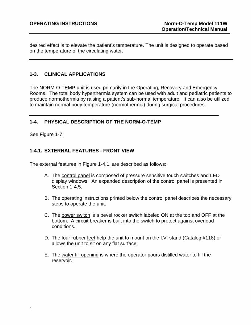
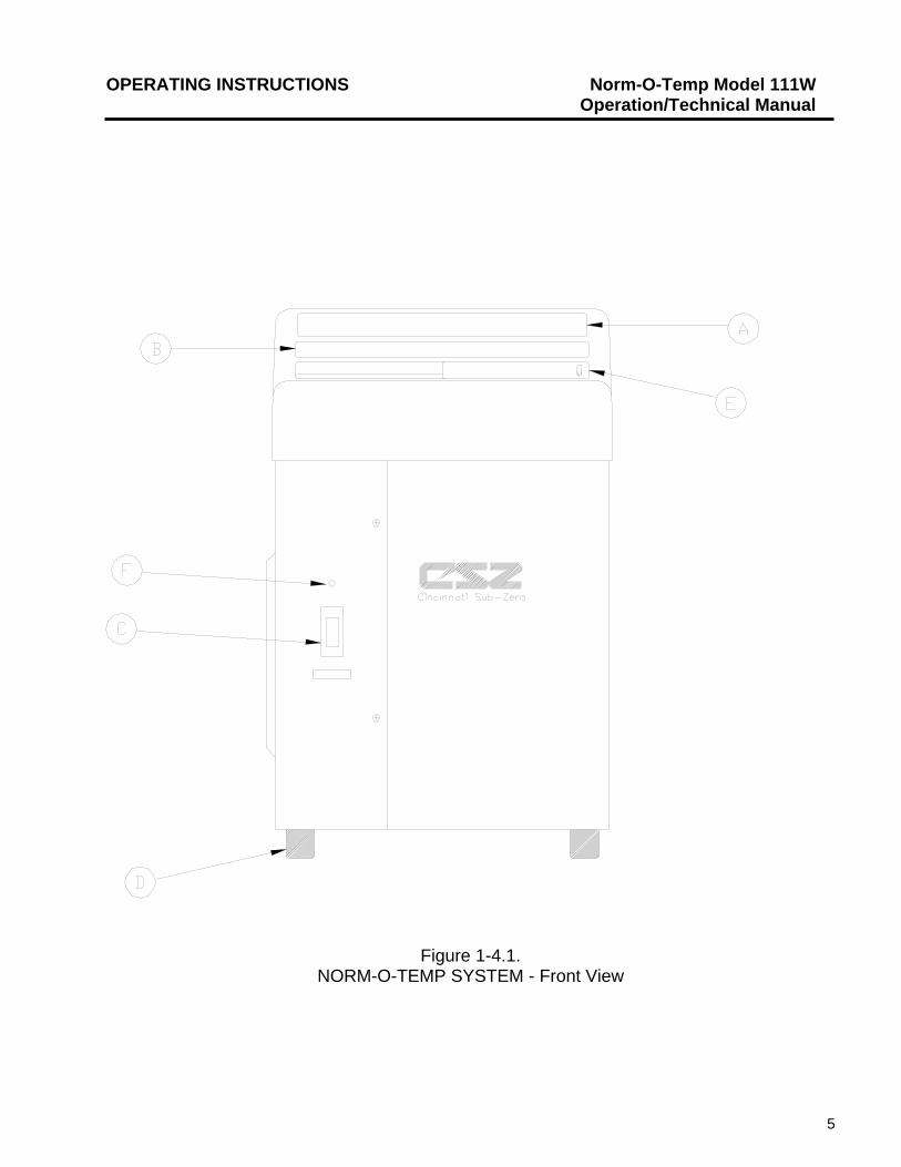
The external features in Figure 1-4.1. are described as follows:
A. The control panel is composed of pressure sensitive touch switches and LED display windows. An expanded description of the control panel is presented in Section 1-4.5.
B. The operating instructions printed below the control panel describes the necessary
steps to operate the unit. C. The power switch is a bevel rocker switch labeled ON at the top and OFF at the
bottom. A circuit breaker is built into the switch to protect against overload conditions.
D. The four rubber feet help the unit to mount on the I.V. stand (Catalog #118) or
allows the unit to sit on any flat surface. E. The water fill opening is where the operator pours distilled water to fill the
reservoir.
4
OPERATING INSTRUCTIONS Norm-O-Temp Model 111W Operation/Technical Manual
Figure 1-4.1. NORM-O-TEMP SYSTEM - Front View
5
OPERATING INSTRUCTIONS Norm-O-Temp Model 111W Operation/Technical Manual
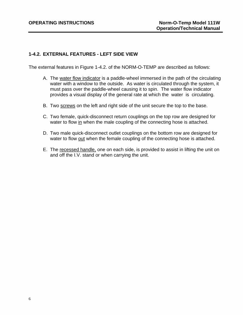
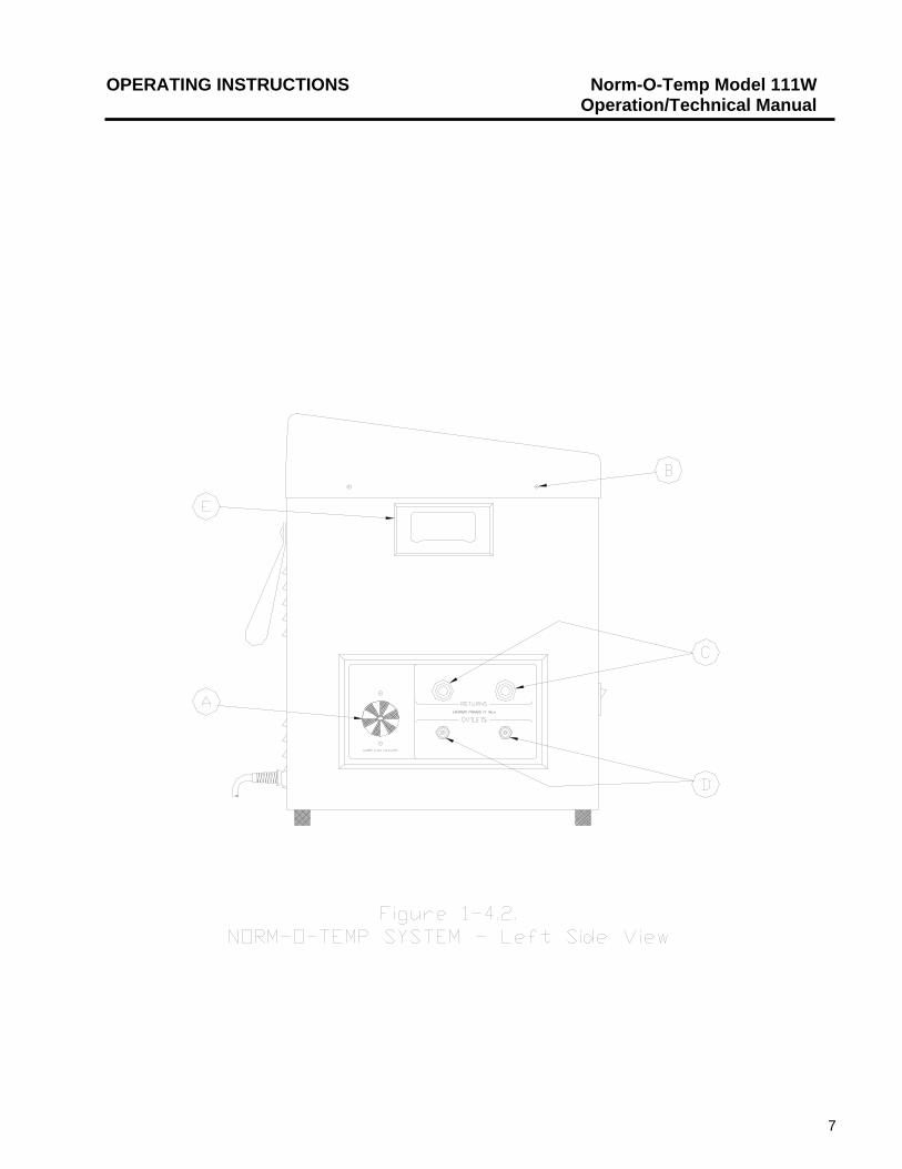
1-4.2. EXTERNAL FEATURES - LEFT SIDE VIEW
The external features in Figure 1-4.2. of the NORM-O-TEMP are described as follows:
A. The water flow indicator is a paddle-wheel immersed in the path of the circulating water with a window to the outside. As water is circulated through the system, it must pass over the paddle-wheel causing it to spin. The water flow indicator provides a visual display of the general rate at which the water is circulating.
B. Two screws on the left and right side of the unit secure the top to the base. C. Two female, quick-disconnect return couplings on the top row are designed for
water to flow in when the male coupling of the connecting hose is attached. D. Two male quick-disconnect outlet couplings on the bottom row are designed for
water to flow out when the female coupling of the connecting hose is attached. E. The recessed handle, one on each side, is provided to assist in lifting the unit on
and off the I.V. stand or when carrying the unit.
6
OPERATING INSTRUCTIONS Norm-O-Temp Model 111W Operation/Technical Manual
7
OPERATING INSTRUCTIONS Norm-O-Temp Model 111W Operation/Technical Manual
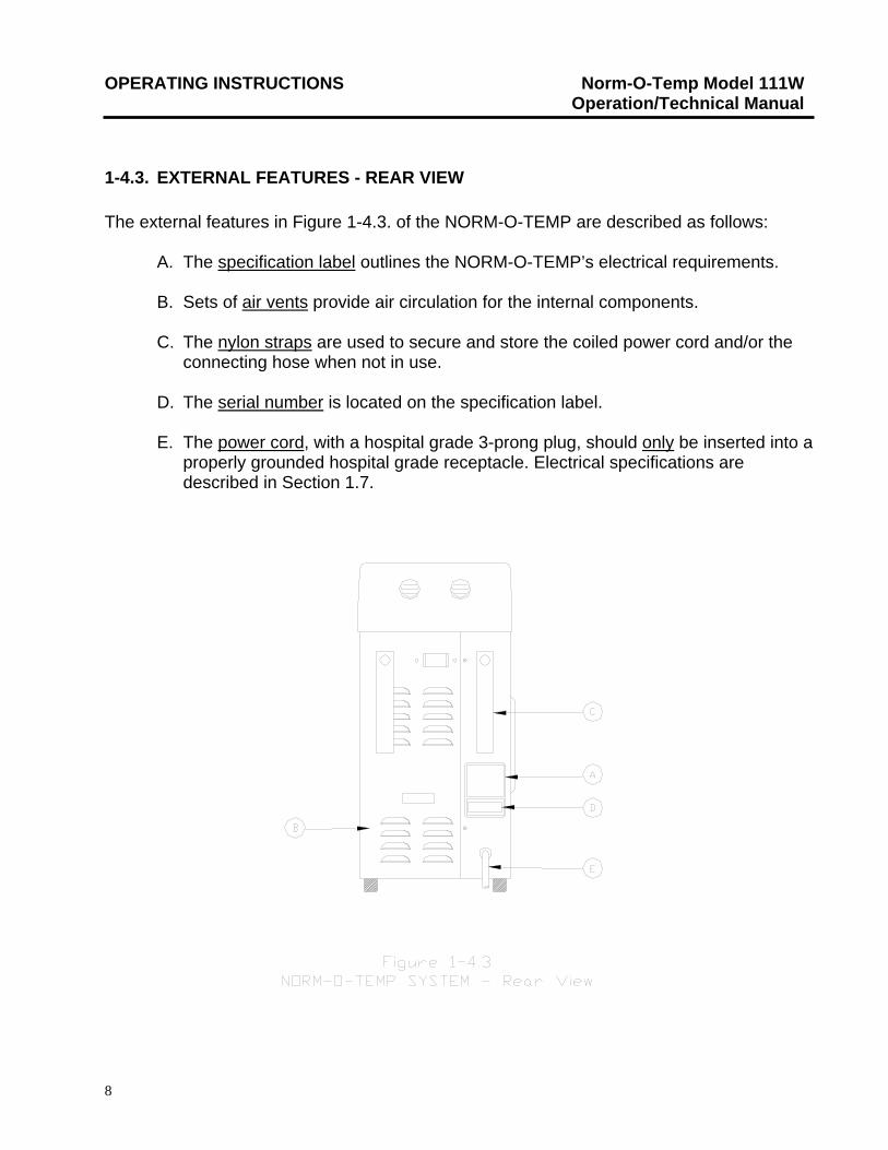
1-4.3. EXTERNAL FEATURES - REAR VIEW The external features in Figure 1-4.3. of the NORM-O-TEMP are described as follows:
A. The specification label outlines the NORM-O-TEMP’s electrical requirements. B. Sets of air vents provide air circulation for the internal components. C. The nylon straps are used to secure and store the coiled power cord and/or the
connecting hose when not in use. D. The serial number is located on the specification label.
E. The power cord, with a hospital grade 3-prong plug, should only be inserted into a
properly grounded hospital grade receptacle. Electrical specifications are described in Section 1.7.
8
OPERATING INSTRUCTIONS Norm-O-Temp Model 111W Operation/Technical Manual
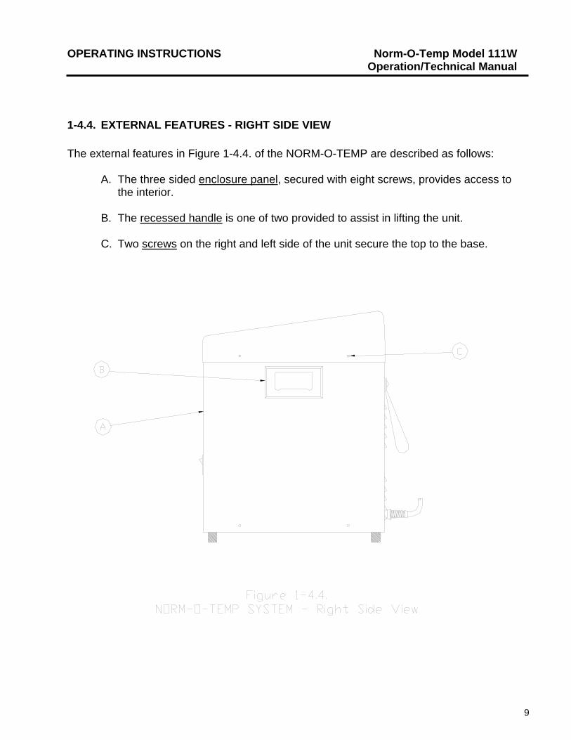
1-4.4. EXTERNAL FEATURES - RIGHT SIDE VIEW The external features in Figure 1-4.4. of the NORM-O-TEMP are described as follows:
A. The three sided enclosure panel, secured with eight screws, provides access to
the interior. B. The recessed handle is one of two provided to assist in lifting the unit. C. Two screws on the right and left side of the unit secure the top to the base.
9
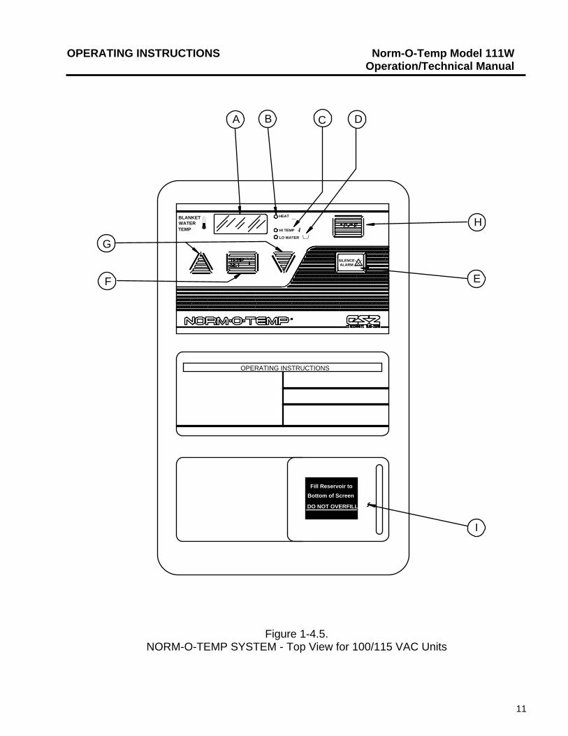
OPERATING INSTRUCTIONS Norm-O-Temp Model 111W Operation/Technical Manual 1-4.5. TOP VIEW DESCRIPTION
The control panels shown in Figure 1-4.5. and 1-4.6. are composed of pressure sensitive touch switches and LED display windows. The control panel is described as follows:
A. The four digit LED display shows the actual water temperature and setpoint
temperature. The temperature display is in Celsius or Fahrenheit.
B. The Heat LED indicates that the water is being heated. C. The Hi Temp LED indicates that the temperature has reached the first or second
safety limit. The LED will flash when the first safety limit has been activated and stays illuminated when the second safety is reached. The LED will be accompanied by an audible alarm as each of the safety limits is reached.
D. The Low Water LED indicates that the unit needs more distilled water to operate.
The LED will be accompanied by an audible alarm. E. The Silence Alarm switch will silence the audible alarm for five minutes and if the
problem is not solved, the alarm will sound again until the switch is pressed or the problem is solved.
F. The Temp Set switch is used to display the desired water temperature. When this
switch is pressed, the display will flash the setpoint temperature for five seconds. G. The UP and DOWN arrow switches are used to raise or lower the setpoint
temperature. There is a five second interval to set the temperature up or down after pressing the Temp Set switch.
H. The C/F Switch will change the display back and forth from Celsius to Fahrenheit.
I. The fill reservoir lid slides to the left to open and to the right to close.
10
OPERATING INSTRUCTIONS Norm-O-Temp Model 111W Operation/Technical Manual
Fill Reservoir to
Bottom of Screen
DO NOT OVERFILL
OPERATING INSTRUCTIONS
SILENCEALARM
HEAT
HI TEMP
LO WATER
BLANKETWATERTEMP
H
E
I
F
G
A B C D
Figure 1-4.5. NORM-O-TEMP SYSTEM - Top View for 100/115 VAC Units
11
OPERATING INSTRUCTIONS Norm-O-Temp Model 111W Operation/Technical Manual 1-5. REQUIRED ACCESSORIES
Operation of the NORM-O-TEMP unit requires the use of a pad through which warm water circulates via a connecting hose with quick-disconnect male and female couplings. NORM-O-TEMP System Equipment and accessories are listed in Figure 7-10. Cincinnati Sub-Zero offers the widest selection of hyper-hypothermia blankets to serve your needs, providing both reusable and single-patient use pads. The reusable pads, the lightweight PLASTIPAD, come with an integral nine-foot connecting hose with quick-disconnect, error proof male and female couplings. Single-patient use pads, MAXI-THERM, MAXI-THERM LITE, TEMP-PAD and a reusable connecting hose are also available. All Cincinnati Sub-Zero blankets offer significantly higher thermal transfer capability than any other brand of hyper-hypothermia blankets. Operation of the NORM-O-TEMP unit requires the use of distilled water. Draining the NORM-O-TEMP unit requires the use of a drain hose with a female coupling. This hose is included with the unit.
1-6. FUNCTIONAL DESCRIPTION OF THE NORM-O-TEMP
The unit heats the water to reach a preset setpoint temperature of *42°C/108°F. The water circulates through the pad(s) which raises and/or maintains the temperature of the patient. There is not a constant relationship between the temperature of the water and the patient’s temperature.
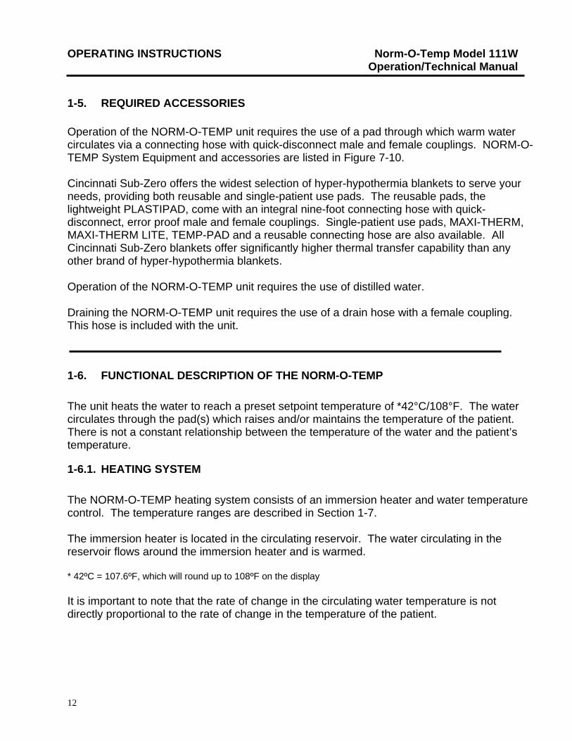
1-6.1. HEATING SYSTEM
The NORM-O-TEMP heating system consists of an immersion heater and water temperature control. The temperature ranges are described in Section 1-7. The immersion heater is located in the circulating reservoir. The water circulating in the reservoir flows around the immersion heater and is warmed. * 42ºC = 107.6ºF, which will round up to 108ºF on the display It is important to note that the rate of change in the circulating water temperature is not directly proportional to the rate of change in the temperature of the patient.
12
OPERATING INSTRUCTIONS Norm-O-Temp Model 111W Operation/Technical Manual 1-6.2. CIRCULATING SYSTEM The NORM-O-TEMP circulating water system is composed of a magnetically driven circulating pump, a dual compartment reservoir, connecting hoses, hyper-hypothermia pad(s) and a flow indicator. The 6 quart (5.6 liter) capacity dual compartment reservoir is composed of the circulating reservoir situated under and connected to the replenishing reservoir. When the operator fills the reservoir with distilled water, the circulating reservoir fills first and holds approximately 1½ quarts (1.4 liters) of water. The remaining 4½ quarts (4.2 liters) are held in the replenishing reservoir. The water moves from the replenishing reservoir to the circulating reservoir by gravitational pull as needed. The circulating water flows over the heating element located in the circulating reservoir. The heated water then flows out the reservoir to the circulating pump, through the pump housing, over the water temperature sensor to the pad(s). The water circulates through the pad(s) and returns to the unit. The water then passes through the water flow indicator and returns to the circulating reservoir to be reheated and then recycled. In addition, the circulating reservoir contains a low water level sensor which shuts down the unit and sounds an alarm if the water level drops below 1½ quarts (1.4 liters). The unit becomes operational after the water level is restored to normal.
1-6.3 TEMPERATURE SAFETY CONTROL SYSTEM
The NORM-O-TEMP is designed to carefully measure and control the temperature of the circulating water. The unit is engineered so that when the temperature of the circulating water reaches the desired setpoint temperature, the heater cycles on and off to maintain the setpoint temperature. As a safety precaution, the NORM-O-TEMP has three high temperature safety limits. Figure 1-6. summarizes the high temperature limits. The microprocessor board continuously monitors the temperature of the circulating water and each unit is protected by an independent back-up safety. As an additional precaution, if the water temperature sensor itself should fail, the unit shuts down, the alarm sounds, and the display will read ERR (for error). With this safety design, the patient is protected from injury and the unit from damage caused by extreme high temperatures.
13
OPERATING INSTRUCTIONS Norm-O-Temp Model 111W Operation/Technical Manual
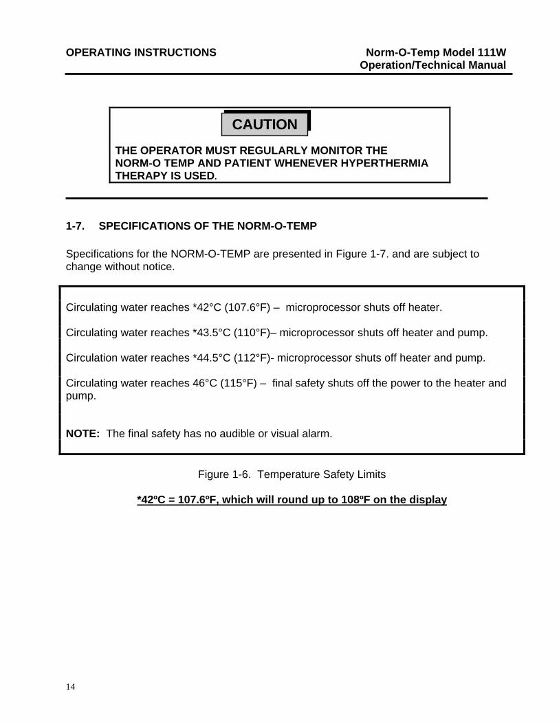
THE OPERATOR MUST REGULARLY MONITOR THE NORM-O TEMP AND PATIENT WHENEVER HYPERTHERMIA THERAPY IS USED.
CAUTION
1-7. SPECIFICATIONS OF THE NORM-O-TEMP Specifications for the NORM-O-TEMP are presented in Figure 1-7. and are subject to change without notice.
Circulating water reaches *42°C (107.6°F) – microprocessor shuts off heater. Circulating water reaches *43.5°C (110°F)– microprocessor shuts off heater and pump. Circulation water reaches *44.5°C (112°F)- microprocessor shuts off heater and pump. Circulating water reaches 46°C (115°F) – final safety shuts off the power to the heater and pump. NOTE: The final safety has no audible or visual alarm.
Figure 1-6. Temperature Safety Limits
*42ºC = 107.6ºF, which will round up to 108ºF on the display
14
OPERATING INSTRUCTIONS Norm-O-Temp Model 111W Operation/Technical Manual
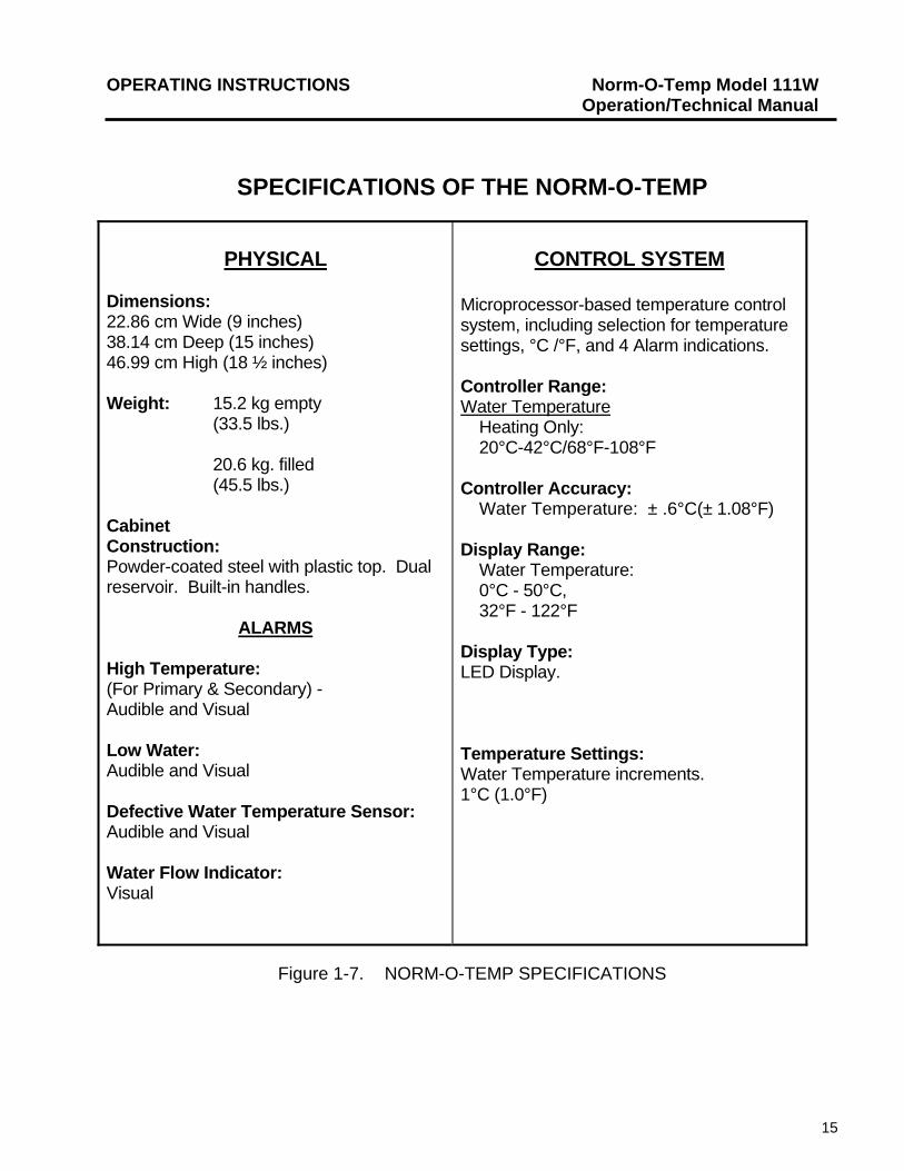
SPECIFICATIONS OF THE NORM-O-TEMP
PHYSICAL
Dimensions: 22.86 cm Wide (9 inches) 38.14 cm Deep (15 inches) 46.99 cm High (18 ½ inches) Weight: 15.2 kg empty (33.5 lbs.) 20.6 kg. filled (45.5 lbs.) Cabinet Construction: Powder-coated steel with plastic top. Dual reservoir. Built-in handles.
ALARMS
High Temperature: (For Primary & Secondary) - Audible and Visual Low Water: Audible and Visual Defective Water Temperature Sensor: Audible and Visual Water Flow Indicator: Visual
CONTROL SYSTEM
Microprocessor-based temperature control system, including selection for temperature settings, °C /°F, and 4 Alarm indications. Controller Range: Water Temperature
Heating Only: 20°C-42°C/68°F-108°F
Controller Accuracy: Water Temperature: ± .6°C(± 1.08°F) Display Range: Water Temperature: 0°C - 50°C, 32°F - 122°F Display Type: LED Display.
Temperature Settings: Water Temperature increments. 1°C (1.0°F)
Figure 1-7. NORM-O-TEMP SPECIFICATIONS
15
OPERATING INSTRUCTIONS Norm-O-Temp Model 111W Operation/Technical Manual
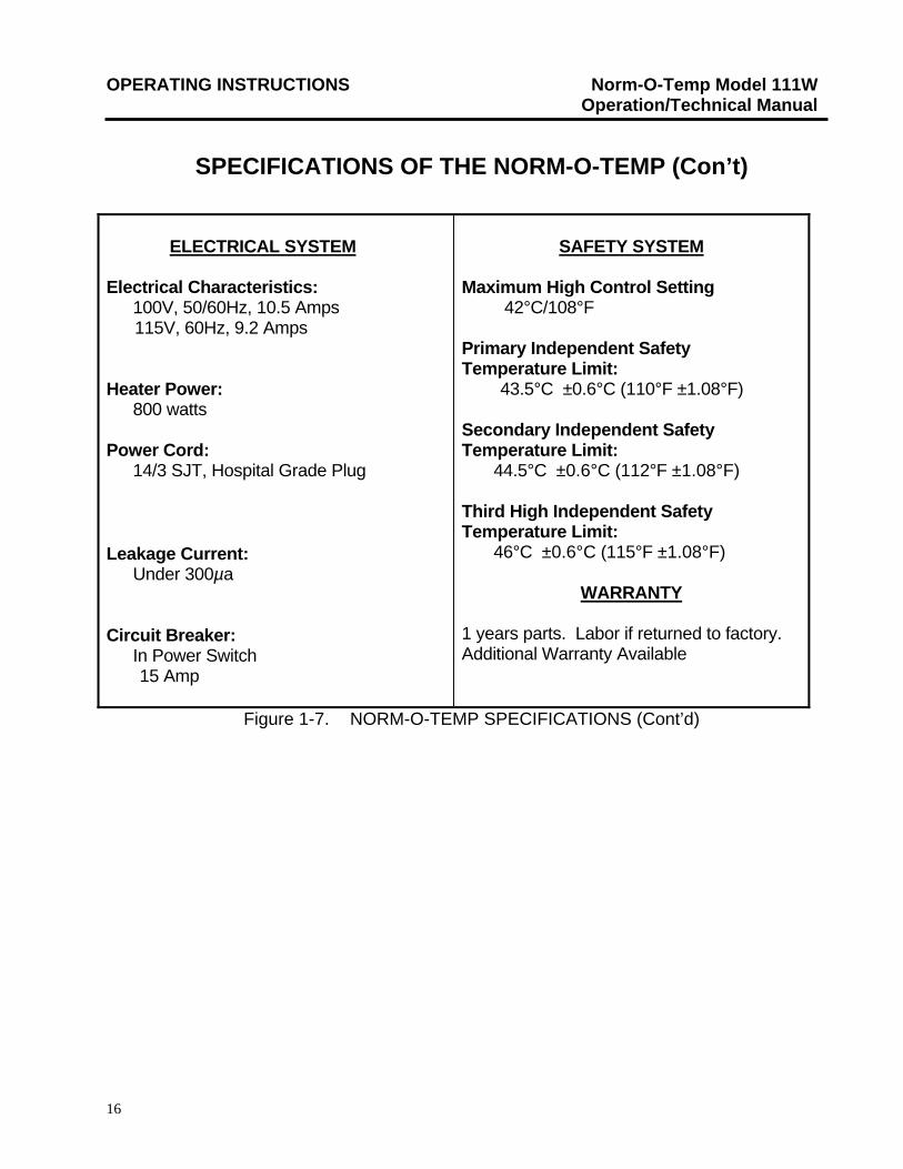
SPECIFICATIONS OF THE NORM-O-TEMP (Con’t)
ELECTRICAL SYSTEM
Electrical Characteristics: 100V, 50/60Hz, 10.5 Amps 115V, 60Hz, 9.2 Amps Heater Power:
800 watts Power Cord:
14/3 SJT, Hospital Grade Plug
Leakage Current: Under 300µa
Circuit Breaker: In Power Switch 15 Amp
SAFETY SYSTEM
Maximum High Control Setting
42°C/108°F
Primary Independent Safety Temperature Limit: 43.5°C ±0.6°C (110°F ±1.08°F) Secondary Independent Safety Temperature Limit: 44.5°C ±0.6°C (112°F ±1.08°F) Third High Independent Safety Temperature Limit: 46°C ±0.6°C (115°F ±1.08°F)
WARRANTY
1 years parts. Labor if returned to factory. Additional Warranty Available
Figure 1-7. NORM-O-TEMP SPECIFICATIONS (Cont’d)
16
OPERATING INSTRUCTIONS Norm-O-Temp Model 111W Operation/Technical Manual
SECTION 2. GENERAL PREPARATION OF THE UNIT
2-1. INTRODUCTION This section describes the procedures to prepare the NORM-O-TEMP for use. This entails unpacking the shipment, arranging all the equipment the first time and completing a test routine. This section also outlines standard safety precautions.
2-2. UNPACKING THE SHIPMENT
Open the top of the carton and remove the top foam insert. Lift the unit from the box. Locate and remove the envelope containing the manual. During the unpacking process, look carefully for signs of shipping damage. If any damage is found, notify the transportation company immediately and file a claim. The transportation company is responsible for the shipment after it leaves the factory. If problems other than shipping damages are found, notify a Cincinnati Sub-Zero representative or the factory.
2-3. FIRST TIME SET-UP/SYSTEM TEST ROUTINE
This section describes the tests necessary to inspect and arrange the equipment the first time after unpacking and describes a system test routine to check out the control panel. The system test routine can also be used to teach operators unfamiliar with the equipment how to use the unit. These tests should be completed prior to assigning the unit for use.
2-3.1. INSPECTING AND ARRANGING THE EQUIPMENT
A. Place the NORM-O-TEMP on an uncluttered work surface that is accessible to the correct power source.
OPTION: The NORM-O-TEMP unit can be mounted on an optional Low Profile
stand with casters or an optional I.V. Stand. For installation instructions, see the insert packaged with the stand.
B. Review Section 1-4. to identify the features of the NORM-O-TEMP.
C. Collect and arrange the following equipment and supplies:
17
OPERATING INSTRUCTIONS Norm-O-Temp Model 111W Operation/Technical Manual
1. Hyper-hypothermia pads as described in Section 1-5.
2. Connecting hose with quick-disconnect fittings if using single-patient use pads.
3. Distilled water. The reservoir holds approximately 6 quarts (5.7 liters).
D. Visually inspect the NORM-O-TEMP to determine that there are no
missing parts, dents or punctures.
E. Examine the power cord for cuts or exposed wires and the plug for straight prongs.
F. Slide the lid of the water fill opening to the left and gradually pour approximately 6 quarts (5.7 liters) of distilled water. Stop pouring when the water reaches the strainer visible at the bottom of the water fill opening.
Connect the pad to the NORM-O-TEMP unit by attaching the quick
disconnect female coupling of the connecting hose to a male outlet coupling (on the bottom row) of the unit. Attach the male quick-disconnect coupling of the connecting hose to the female return coupling (on the top row) of the unit. Each pad must be connected to one outlet and one return.
G. Check that the pad is laying flat and that the connecting hose to the unit is
not twisted or pinched. H. Check that the power switch of the unit is in the OFF position.
Insert the 3-prong plug (in a properly grounded hospital-grade receptacle).
WARNING
Do not by-pass the ground plug. Electrical hazards may result.
2-3.2. COMPLETING A SYSTEM TEST ROUTINE
After arranging the equipment as described in Section 2-3.1., complete this System Test Routine which describes what switches to press and the changes to observe.
A. Press the Power switch to the ON position.
1. The switch lights up green.
18
OPERATING INSTRUCTIONS Norm-O-Temp Model 111W Operation/Technical Manual
2. A beeper sounds. * 42ºC = 107.6ºF, which will round up to 108ºF on the display
3. The seven segment display flashes the setpoint temperature *42°C/107°F a few seconds.
4. All segments of the seven segment display flash on and off (888’s) for a few
seconds along with the LED’s.
5. A beeper sounds. 6. The seven segment display reads CAL for several seconds and the unit
begins to pump and heat the water. 7. The seven segment display will show the actual water temperature.
8. The Heat LED will light up if the water temperature is less than
*42°C/107°F.
If any of the above is not observed, consult the Troubleshooting Guide in Section 6. If they are all observed, continue with the test routine. If at any time the water falls below the minimum level, the Low Water indicator is activated and the alarm sounds.
B. Press the C/F switch - a beeper sounds.
1. The seven segment display changes from *42°C to 107°F.
C. Press the C/F switch again - a beeper sounds.
1. The seven segment display changes from *107°F to 42°C.
D. Press the Temp Set switch.
1. A beeper sounds. 2. The seven segment display will begin to flash the setpoint temperature
*42°C/107°F. Each time the operator presses the Temp Set switch after just having turned on the unit, the setpoint temperature will display *42°C/ 107°F.
* 42ºC = 107.6ºF, which will round up to 108ºF on the display 3. After pressing the Temp Set switch, the operator has five seconds to
change the setpoint temperature by pressing either the UP or DOWN arrows.
19
OPERATING INSTRUCTIONS Norm-O-Temp Model 111W Operation/Technical Manual
4. After the five second interval has elapsed, the seven segment display reverts to displaying the actual water temperature.
E. Press the UP arrow during the five second interval after pressing the
Temp Set switch.
1. A beeper sounds each time it is pressed but does not beep when held down continuously.
2. The setpoint display changes; the numbers move up the scale. The highest
setting is *42°C/107°F.
F. Press the DOWN arrow during the five second interval after pressing the Temp Set switch.
1. A beeper sounds each time it is pressed but does not beep when held down
continuously. 2. The setpoint display changes; the numbers move down the scale. The
lowest setting is 20°C (68°F).
G. To complete this test routine, press the Power switch to the “OFF” position.
1. The control panel goes blank.
2. The Power switch light goes out.
3. The water flow indicator stops.
H. Disconnect the power cord, loosely coil it and attach it to the nylon strap on the back of the unit.
I. If using reusable pads, disconnect the connecting hose from the unit.
Loosely coil the hose lengthwise in the center of the pad. Fold the pad lengthwise into the center, 1/3 from the left side and 1/3 from the right side. The water can remain in the pad and in the unit between short periods of use. If using single-patient use pads, follow the instructions packaged with the pad. The water should be changed monthly as described in Section 4-2.
20
OPERATING INSTRUCTIONS Norm-O-Temp Model 111W Operation/Technical Manual
It is important that the pads are disconnected to prevent gravity flow of water back into the NORM-O-TEMP, causing it to overflow.
2-4. UNIT AND PATIENT RELATED PRECAUTIONS
CAUTION
This unit requires both water and electricity in order to operate.
Any time water is found leaking into or around the unit or the connecting hose, turn the unit off, disconnect the power cord, and correct the problem before proceeding.
Exercise extreme caution if the unit is used for patients who are electrically susceptible (probe, catheter or electrodes directly connected to the heart).
A. Test for leakage current prior to general floor use.
WARNING
CAUTION
*See Section 5-18.2.
B. Any time a repair is made, unplug the power cord before disassembly.
C. The repair and servicing of the NORM-O-TEMP as described in Section 5 requires no special tools. However, only persons with the proper skills and knowledge should undertake any repairs, servicing or maintenance of the unit.
D. The high temperature safety limits protect the patient from injury and the unit from
damage that can be caused by extreme temperatures. Nonetheless, the patient’s temperature should be monitored frequently.
E. Any time the unit sounds an alarm, immediately check the LED’s and the seven
segment display; then take appropriate action to correct the problem.
21
OPERATING INSTRUCTIONS Norm-O-Temp Model 111W Operation/Technical Manual
F. The NORM-O-TEMP is equipped with a circuit breaker in the ON/OFF power switch for 100/115 VAC to protect against current overload.
2-5. PATIENT PREPARATION AND BEDSIDE CARE
Effective use of the NORM-O-TEMP must include proper patient care prior to and while using the hyper-hypothermia pad(s).
The desired setpoint temperature should be set only as prescribed by and under the order of a physician.
A. A base line recording should be made of vital signs, level of consciousness and
responsiveness.
CAUTION
B. A dry sheet should be placed between the hyper-hypothermia pad and the patient
when using PLASTI-PAD, MAXI-THERM, or TEMP-PAD Products. The MAXI-THERM LITE and do not require an interposed sheet.
Standard nursing procedures while using a hyper-hypothermia pad include the following tasks:
A. Patient’s vital signs should be recorded and evaluated frequently. Operating room, temperature sensitive, and pediatric patients may deviate from normal responses to external application of heat.
B. Level of consciousness, strength of extremities, changes in cardiac rate, changes
in cardiac rhythms, pupil size, and response should be observed and recorded. C. Changes in skin color, edema, inflammation, or indications of pressure, especially
over bony prominences should be noted and treated as ordered. Avoid prolonged tissue and shearing forces over bony prominences.
D. Urinary output and specific gravity should be accurately recorded every hour. E. The patient should be turned and properly positioned frequently.
22
OPERATING INSTRUCTIONS Norm-O-Temp Model 111W Operation/Technical Manual
WARNING
The patient should be constantly attended. The misuse of hyper-hypothermia equipment presents the potential for patient injury.
THE APPLICATION OF HEATING OR COOLING MAY EFFECT THE TOXICITY OF PREP SOLUTIONS. PREP SOLUTIONS HAVE BEEN REPORTED TO INJURE THE SKIN WHEN ALLOWED TO REMAIN BETWEEN PATIENTS AND A WATER-CIRCULATING HEATING PADS DURING PROLONGED PROCEDURES. KEEP THE AREA BETWEEN THE PATIENT AND THE PAD DRY.
CAUTION
23
OPERATING INSTRUCTIONS Norm-O-Temp Model 111W Operation/Technical Manual
SECTION 3. OPERATING THE NORM-O-TEMP
3-1. INTRODUCTION
This section describes how to operate the NORM-O-TEMP in order to monitor the pad/water temperature.
3-2. ARRANGING THE COMPONENTS
A. Collect all supplies and equipment.
1. NORM-O-TEMP 2. Hyper-hypothermia PAD(s) 3. Dry sheet or bath blanket 4. Connecting hose if using MAXI-THERM, MAXI-THERM LITE, or
TEMP-PAD single-patient use disposable products or reusable pad. 5. Distilled water.
B. Place the NORM-O-TEMP in an area accessible to the correct power source.
C. Review Section 1-4. which outlines the features of the unit and control panel. D. Check the level of distilled water in the reservoir by sliding the cover of the water
fill opening to the left. The water should be visible, touching the strainer. If needed, carefully add distilled water. If the water falls below a pre-set minimum level, the Low Water LED lights up and the alarm sounds. The pump and heater shut down and the operator cannot proceed until this is corrected.
E. Be sure the power switch is in the “OFF” position for .
F. Inspect the power plug. G. Insert the power cord plug into a properly grounded hospital grade receptacle.
24
OPERATING INSTRUCTIONS Norm-O-Temp Model 111W Operation/Technical Manual
WARNING
Do not by-pass the ground plug; electrical hazards may result. Do not use an extension cord.
H. Lay the hyper-hypothermia pad flat with the hose routed, without kinks, towards
the unit. I. If the pad is already filled, be sure there are no leaks.
J. Cover the pad with a dry sheet or bath blanket (if using PLASTI-PAD, MAXI-
THERM, or TEMP-PAD Products).
K. Connect the pad to the NORM-O-TEMP as described in Section 2-3.1., step G. L. Connect the couplings of the connecting hose to the pad as described in the
instructions packaged with each pad. M. Be sure the pad is flat and that the connecting hose is not twisted or pinched. N. The hyper-hypothermia pad can be prewarmed before positioning the patient. To
do so, operate the unit for a few minutes. O. Place the patient on the hyper-hypothermia pad.
P. If a top hyper-hypothermia pad is to be used, place a sheet between the patient
and the thermal pad.
Q. Connect the top pad to the NORM-O-TEMP unit as described in Section 2-3.1., step G.
R. If no top hyper-hypothermia pad is used, cover the patient with a top sheet and/or
blanket. Patient preparation and bedside care are further described in Section 2-5.
25
OPERATING INSTRUCTIONS Norm-O-Temp Model 111W Operation/Technical Manual
26
3-3. OPERATING THE NORM-O-TEMP
The NORM-O-TEMP operates based upon the actual temperature of the circulating water relative to the setpoint temperature. The NORM-O-TEMP heats and circulates the water. Given the many variables such as patient size, weight, or condition, there is no direct relationship between the temperature of the circulating water and patient temperature. Both water temperature and patient temperature should be closely monitored. After arranging the equipment as described in Section 3-2, proceed as directed in Section 2-3.2.
3-4. CONCLUDING THE USE OF THE NORM-O-TEMP
See Section 2-3.2. NOTE: It is important that the pads are disconnected to prevent
gravity flow of water back into the Norm-O-Temp, causing it to overflow.
TROUBLESHOOTING Norm-O-Temp Model 111W, Operation/Technical Manual
27
SECTION 4. GENERAL MAINTENANCE OF THE NORM-O-TEMP
4-1. INTRODUCTION
This section describes the general tasks maintenance personnel should complete on a regular basis so that the NORM-O-TEMP continues to operate smoothly. Figure 4-3. provides a convenient checklist to record the maintenance history of the unit. The description of each task includes the tools, the procedures and the precautions necessary to complete the task. Maintenance, repair and/or service of the NORM-O-TEMP by qualified maintenance/technical personnel will not void the warranty of the unit.
DANGER
The repair, calibration, and servicing of the Norm-O-Temp should be performed by qualified Medical Equipment Service Technicians, Certified Biomedical Electronics Technicians, or Certified Clinical Engineers familiar with good repair practices for servicing medical devices, and in accordance with instructions contained in this manual. Improper repair can result in patient injury and damage to the Norm-O-Temp unit.
TROUBLESHOOTING Norm-O-Temp Model 111W, Operation/Technical Manual
28
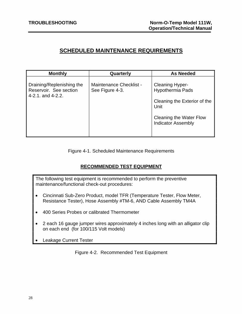
SCHEDULED MAINTENANCE REQUIREMENTS
Monthly Quarterly As Needed Draining/Replenishing the Reservoir. See section 4-2.1. and 4-2.2.
Maintenance Checklist - See Figure 4-3.
Cleaning Hyper-Hypothermia Pads Cleaning the Exterior of the Unit Cleaning the Water Flow Indicator Assembly
Figure 4-1. Scheduled Maintenance Requirements
RECOMMENDED TEST EQUIPMENT
The following test equipment is recommended to perform the preventive maintenance/functional check-out procedures: Cincinnati Sub-Zero Product, model TFR (Temperature Tester, Flow Meter,
Resistance Tester), Hose Assembly #TM-6, AND Cable Assembly TM4A 400 Series Probes or calibrated Thermometer 2 each 16 gauge jumper wires approximately 4 inches long with an alligator clip
on each end (for 100/115 Volt models) Leakage Current Tester
Figure 4-2. Recommended Test Equipment

TROUBLESHOOTING Norm-O-Temp Model 111W, Operation/Technical Manual
29
Figure 4-3 SUGGESTED PREVENTIVE MAINTENANCE CHECKLIST
(At Least Quarterly)
NORM-O-TEMP Model 111W Serial Number Hospital I.D. No. Check When Completed
1. External cabinet in good condition.
(No unusual dents or missing parts)
2. All labels properly affixed.
3. Condition of blankets, hoses, and couplings (check for
leaks). Connecting hoses are tight and not leaking.
4. Power cord (no cuts or exposed wire) and plug
(no bent or missing prongs).
5. Membrane Control Panel, Seven Segment Displays and
LED’s are operative.
6. Clean water filter assembly as described in Section
4-3.
7. Perform the Decontamination Procedure for the water
system as described in Section 4-4. 8. Check flow rate and pressure.
Greater than .60 GPM Less than 10 PSI.
TROUBLESHOOTING Norm-O-Temp Model 111W, Operation/Technical Manual
30
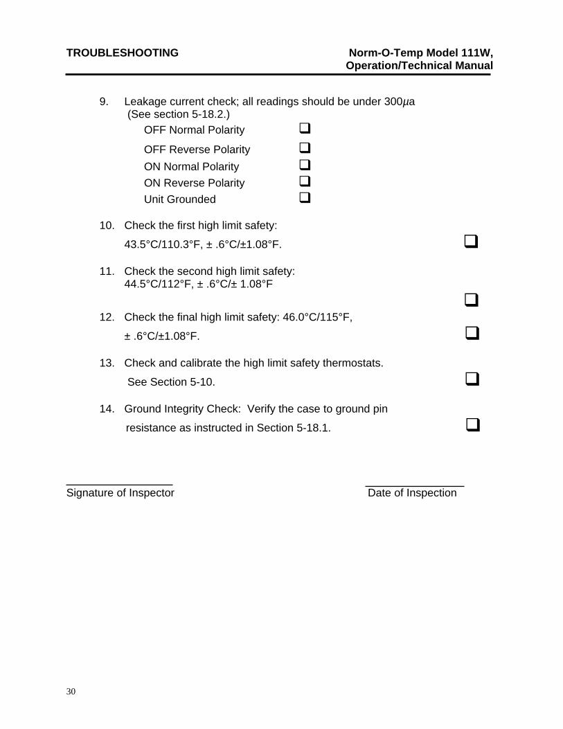
9. Leakage current check; all readings should be under 300µa (See section 5-18.2.)
OFF Normal Polarity
OFF Reverse Polarity
ON Normal Polarity
ON Reverse Polarity
Unit Grounded
10. Check the first high limit safety:
43.5°C/110.3°F, ± .6°C/±1.08°F. 11. Check the second high limit safety: 44.5°C/112°F, ± .6°C/± 1.08°F
12. Check the final high limit safety: 46.0°C/115°F,
± .6°C/±1.08°F. 13. Check and calibrate the high limit safety thermostats.
See Section 5-10. 14. Ground Integrity Check: Verify the case to ground pin
resistance as instructed in Section 5-18.1. Signature of Inspector Date of Inspection
TROUBLESHOOTING Norm-O-Temp Model 111W, Operation/Technical Manual
31
4-2. MAINTENANCE OF THE WATER RESERVOIR The dual compartment reservoir holds approximately 6 quarts (5.7 liters) of distilled water that remains in the unit between periods of use. Quarterly, the water reservoir should be drained and replenished. The drain hose, included in the packaging of the unit, is attached to the unit and then the water is pumped out of the unit. When the LO WATER alarm sounds, the remaining water is drained by gravity. Pour distilled water into the reservoir.
DO NOT USE DE-IONIZED WATER. The majority of de-ionizers do not maintain a neutral pH of 7.
SUGGESTED DECONTAMINATION GUIDELINES FOR CINCINNATI SUB-ZERO EQUIPMENT is outlined in Section 4-4.
CAUTION
4-2.1. DRAINING THE RESERVOIR
A. Collect these items
1. An empty container, to drain the water into, that can hold at least 2 gallons (7.6 liters).
2. The drain hose with a female quick-disconnect coupling. 3. 6 quarts (5.7 liters) distilled water to replenish the reservoir.
B. Insert the drain end of the hose into the 2 gallon (7.6 liter) container. Place the container (lower than unit) so that the water drains away.
C. Attach the female coupling of the drain hose to any one of the male outlet
couplings on the left side of the unit. D. Insert the power cord plug into a properly grounded hospital grade
receptacle. E. Press the power switch to the ON position.
The water is pumped into the container until there is approximately 2 quarts (1.9 liters) of water remaining to be drained. The LO WATER indicator lights up, the status display flashes, and the alarm sounds. The unit shuts down, but the water continues to drain into the container because of gravitational pull.
F. Press the power switch to the OFF position.
TROUBLESHOOTING Norm-O-Temp Model 111W, Operation/Technical Manual
32
G. Disconnect the unit from its power source. H. After all the water has drained from the unit, disconnect the drain hose,
wipe and store. I. Discard the water drained from the unit. J. If any other maintenance/repair is to be completed, go to the appropriate
section, e.g., maintenance of the water filter. If not, go to Section 4-2.2. to replenish the reservoir.
4-2.2. REPLENISHING THE RESERVOIR
A. Be sure the drain hose is disconnected. B. Slide the water fill opening lid to the left and gradually pour approximately 6
quarts (5.7 liters) of distilled water into the reservoir. C. Stop pouring when the water reaches the strainer visible at the bottom of the
water fill opening. D. Proceed with normal operations; always check the water level before starting.
4-3 MAINTENANCE OF THE WATER FILTER
The NORM-O-TEMP circulating system includes a water filter. As shown in Figure 7-1., the water filter assembly is a plastic T-shaped fitting which intersects the hose from the water flow indicator to the reservoir. A stainless steel wire-mesh screen is located inside the clear plastic cap of the water filter assembly. Quarterly, the water filter should be disassembled and cleaned. To do so, the reservoir must first be drained and the three sided enclosure panel removed. The cap of the water filter assembly is unscrewed and the wire mesh and the plastic cap are cleaned. The parts are then reassembled.
After draining the reservoir as described in Section 4-2.1.:
A. Be sure the unit is disconnected from the power source.
B. Remove the three sided enclosure panel as described in Section 5-2.3.
C. Locate the water filter assembly as shown in Figure 7-1, item #13.
TROUBLESHOOTING Norm-O-Temp Model 111W, Operation/Technical Manual
33
D. Firmly grasp the notched rim of the cap of the assembly and turn counterclockwise. The cap may contain a small amount of water.
E. Remove the wire mesh.
F. Clean the wire mesh and the plastic cap. Be careful not to lose the black O-ring in the rim of the plastic cap.
G. Replace the wire mesh in the plastic cap and position the wire mesh, O-ring and plastic cap under the fitting.
H. Securely screw the cap clockwise onto the fitting.
I. Replace the three-sided enclosure panel as described in Section 5-2.4.
J. Replenish the water reservoir as described in Section 4-2.2.
4-4 MAINTENANCE OF THE WATER CIRCULATING SYSTEM Quarterly, at a minimum, the FLUID CIRCUIT DISINFECTION/DRY STORAGE PROCEDURE, listed below, should be conducted.
CAUTION For safe handling and use of chemicals follow manufacturer guidelines.
Always drain the Norm-O-temp to a sanitary drain because bio-contaminants may be present in the unit’s water supply.
Chemical Cleaning Circulation Chart UNIT MODE TEMPERATURE DURATION
Norm-O-Temp 111W
Heating 38°C 5 Minutes
FLUID CIRCUIT DISINFECTION/DRY STORAGE PROCEDURE for Circulating Water Units Utilizing Household Bleach
The following procedure disinfects the fluid circuit in these products. The required tools/supplies are appropriate drain hose(s) and/or hose connector(s), household bleach, distilled water, U.S.P. Grade Propylene Glycol, and the appropriate AC electrical power
TROUBLESHOOTING Norm-O-Temp Model 111W, Operation/Technical Manual
34
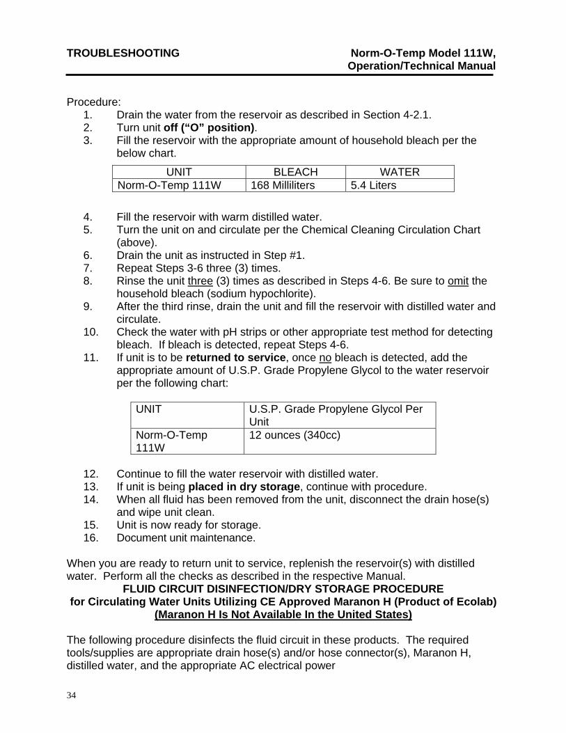
Procedure: 1. Drain the water from the reservoir as described in Section 4-2.1. 2. Turn unit off (“O” position). 3. Fill the reservoir with the appropriate amount of household bleach per the
below chart.
UNIT BLEACH WATER Norm-O-Temp 111W 168 Milliliters 5.4 Liters
4. Fill the reservoir with warm distilled water. 5. Turn the unit on and circulate per the Chemical Cleaning Circulation Chart
(above). 6. Drain the unit as instructed in Step #1. 7. Repeat Steps 3-6 three (3) times. 8. Rinse the unit three (3) times as described in Steps 4-6. Be sure to omit the
household bleach (sodium hypochlorite). 9. After the third rinse, drain the unit and fill the reservoir with distilled water and
circulate. 10. Check the water with pH strips or other appropriate test method for detecting
bleach. If bleach is detected, repeat Steps 4-6. 11. If unit is to be returned to service, once no bleach is detected, add the
appropriate amount of U.S.P. Grade Propylene Glycol to the water reservoir per the following chart:
UNIT U.S.P. Grade Propylene Glycol Per
Unit Norm-O-Temp 111W
12 ounces (340cc)
12. Continue to fill the water reservoir with distilled water. 13. If unit is being placed in dry storage, continue with procedure. 14. When all fluid has been removed from the unit, disconnect the drain hose(s)
and wipe unit clean. 15. Unit is now ready for storage. 16. Document unit maintenance.
When you are ready to return unit to service, replenish the reservoir(s) with distilled water. Perform all the checks as described in the respective Manual.
FLUID CIRCUIT DISINFECTION/DRY STORAGE PROCEDURE for Circulating Water Units Utilizing CE Approved Maranon H (Product of Ecolab)
(Maranon H Is Not Available In the United States) The following procedure disinfects the fluid circuit in these products. The required tools/supplies are appropriate drain hose(s) and/or hose connector(s), Maranon H, distilled water, and the appropriate AC electrical power
TROUBLESHOOTING Norm-O-Temp Model 111W, Operation/Technical Manual
35
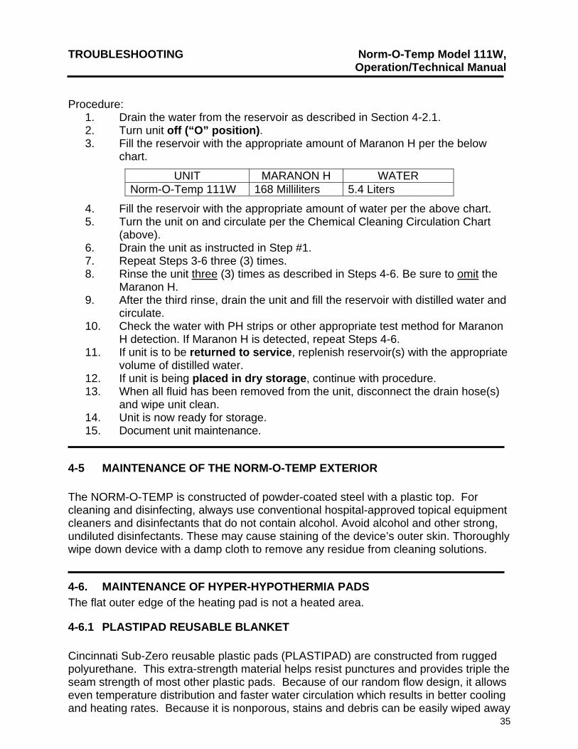
Procedure: 1. Drain the water from the reservoir as described in Section 4-2.1. 2. Turn unit off (“O” position). 3. Fill the reservoir with the appropriate amount of Maranon H per the below
chart.
UNIT MARANON H WATER Norm-O-Temp 111W 168 Milliliters
4. Fill the reservoir with the appropriate amount of water per the above chart. 5. Turn the unit on and circulate per the Chemical Cleaning Circulation Chart
(above). 6. Drain the unit as instructed in Step #1. 7. Repeat Steps 3-6 three (3) times. 8. Rinse the unit three (3) times as described in Steps 4-6. Be sure to omit the
Maranon H. 9. After the third rinse, drain the unit and fill the reservoir with distilled water and
circulate. 10. Check the water with PH strips or other appropriate test method for Maranon
H detection. If Maranon H is detected, repeat Steps 4-6. 11. If unit is to be returned to service, replenish reservoir(s) with the appropriate
volume of distilled water. 12. If unit is being placed in dry storage, continue with procedure. 13. When all fluid has been removed from the unit, disconnect the drain hose(s)
and wipe unit clean. 14. Unit is now ready for storage. 15. Document unit maintenance.
4-5 MAINTENANCE OF THE NORM-O-TEMP EXTERIOR
The NORM-O-TEMP is constructed of powder-coated steel with a plastic top. For cleaning and disinfecting, always use conventional hospital-approved topical equipment cleaners and disinfectants that do not contain alcohol. Avoid alcohol and other strong, undiluted disinfectants. These may cause staining of the device’s outer skin. Thoroughly wipe down device with a damp cloth to remove any residue from cleaning solutions.
5.4 Liters
4-6. MAINTENANCE OF HYPER-HYPOTHERMIA PADS
The flat outer edge of the heating pad is not a heated area.
4-6.1 PLASTIPAD REUSABLE BLANKET Cincinnati Sub-Zero reusable plastic pads (PLASTIPAD) are constructed from rugged polyurethane. This extra-strength material helps resist punctures and provides triple the seam strength of most other plastic pads. Because of our random flow design, it allows even temperature distribution and faster water circulation which results in better cooling and heating rates. Because it is nonporous, stains and debris can be easily wiped away
TROUBLESHOOTING Norm-O-Temp Model 111W, Operation/Technical Manual
36
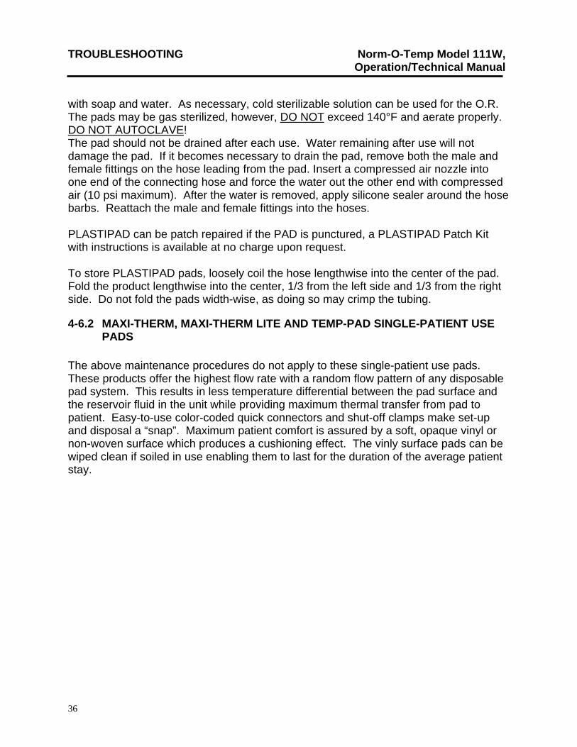
with soap and water. As necessary, cold sterilizable solution can be used for the O.R. The pads may be gas sterilized, however, DO NOT exceed 140°F and aerate properly. DO NOT AUTOCLAVE! The pad should not be drained after each use. Water remaining after use will not damage the pad. If it becomes necessary to drain the pad, remove both the male and female fittings on the hose leading from the pad. Insert a compressed air nozzle into one end of the connecting hose and force the water out the other end with compressed air (10 psi maximum). After the water is removed, apply silicone sealer around the hose barbs. Reattach the male and female fittings into the hoses. PLASTIPAD can be patch repaired if the PAD is punctured, a PLASTIPAD Patch Kit with instructions is available at no charge upon request. To store PLASTIPAD pads, loosely coil the hose lengthwise into the center of the pad. Fold the product lengthwise into the center, 1/3 from the left side and 1/3 from the right side. Do not fold the pads width-wise, as doing so may crimp the tubing.
4-6.2 MAXI-THERM, MAXI-THERM LITE AND TEMP-PAD SINGLE-PATIENT USE PADS
The above maintenance procedures do not apply to these single-patient use pads. These products offer the highest flow rate with a random flow pattern of any disposable pad system. This results in less temperature differential between the pad surface and the reservoir fluid in the unit while providing maximum thermal transfer from pad to patient. Easy-to-use color-coded quick connectors and shut-off clamps make set-up and disposal a “snap”. Maximum patient comfort is assured by a soft, opaque vinyl or non-woven surface which produces a cushioning effect. The vinly surface pads can be wiped clean if soiled in use enabling them to last for the duration of the average patient stay.
TROUBLESHOOTING Norm-O-Temp Model 111W, Operation/Technical Manual
37
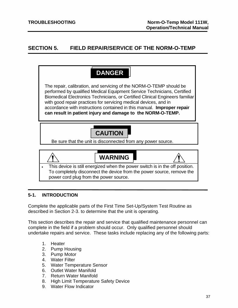
SECTION 5. FIELD REPAIR/SERVICE OF THE NORM-O-TEMP
Be sure that the unit is disconnected from any power source.
This device is still energized when the power switch is in the off position. To completely disconnect the device from the power source, remove the power cord plug from the power source.
WARNING
CAUTION
The repair, calibration, and servicing of the NORM-O-TEMP should be performed by qualified Medical Equipment Service Technicians, Certified Biomedical Electronics Technicians, or Certified Clinical Engineers familiar with good repair practices for servicing medical devices, and in accordance with instructions contained in this manual. Improper repair can result in patient injury and damage to the NORM-O-TEMP.
DANGER
5-1. INTRODUCTION Complete the applicable parts of the First Time Set-Up/System Test Routine as described in Section 2-3. to determine that the unit is operating. This section describes the repair and service that qualified maintenance personnel can complete in the field if a problem should occur. Only qualified personnel should undertake repairs and service. These tasks include replacing any of the following parts:
1. Heater 2. Pump Housing 3. Pump Motor 4. Water Filter 5. Water Temperature Sensor 6. Outlet Water Manifold 7. Return Water Manifold 8. High Limit Temperature Safety Device 9. Water Flow Indicator
TROUBLESHOOTING Norm-O-Temp Model 111W, Operation/Technical Manual
38
10. Power Switch 11. Solid State Relays 12. Water Level Sensor 13. Transformer 14. Microprocessor Control Board 15. Membrane Control Panel
The description of each task includes the tools, the procedures and the precautions necessary to complete the task. Maintenance, repair and/or service of the NORM-O-TEMP by qualified maintenance/technical personnel will not void the warranty. Figures 7-1. and 7-3. highlight the interior components of the NORM-O-TEMP. Any part that is removed from the unit and is still under warranty should be returned to Cincinnati Sub-Zero as described in Section 7. If not, dispose of the part as required. Before attempting to perform any service or make any repairs, disconnect the NORM-O-TEMP unit from any power source.
5-2. ACCESS TO THE INTERIOR
All internal operating components are readily accessible by either removing the top of the unit or the three sided enclosure panel. It is recommended that the reservoir be drained and the power cord disconnected before removing any part of the unit.
5-2.1. REMOVING THE TOP OF THE UNIT
Working with electronic boards, plugs, and cables requires delicate handling. Proper Electrostatic Discharge (ESD) handling procedures should be followed during replacement of any electronic board. It is recommended that this section be read before removing the microprocessor board and/or the membrane control panel.
A. Remove the four phillips head screws from the top assembly.
CAUTION
B. Carefully lift up the top so that you can see the two solid state relays,
microprocessor board, and the two connecting cables. C. Wipe dry the strainer and any water that may have dripped. D. Disconnect the 9-pin connector by pinching the sides and pulling apart.
TROUBLESHOOTING Norm-O-Temp Model 111W, Operation/Technical Manual
39
E. Disconnect the 12-pin connector by pinching the sides and pulling apart. F. Lift the top up and put it aside or discard if being replaced.
5-2.2. REPLACE/REINSTALL THE TOP OF THE UNIT
Re-Install top as it was removed in section 5-2.1.
NOTE: When securing the top, be sure the fill spout gasket inner lip on the aluminum cover top is in the up position and the fill spout goes directly into it.
5-2.3. REMOVING THE THREE SIDED ENCLOSURE PANEL
A. Loosen the top of the unit as described in Section 5-2.1. B. If an I.V. pole is attached to the stand, remove the two phillips screws from the U-
shaped bracket that secures the I.V. pole to the unit. Put the bracket and screws aside.
C. Remove the six remaining phillips head screws that secure the three-sided panel
to the unit. D. Guide the panel straight out but not all the way off. E. Disconnect the male 2-pin connector on the fan from the female 2-pin connector
on the wiring harness. F. Remove the enclosure panel and put aside or discard if it is being replaced.
5-2.4. REPLACE/REINSTALL THE THREE-SIDED ENCLOSURE PANEL
Re-Install enclosure as it was removed in section 5-2.3.
5-3. REPLACEMENT OF THE HEATER
A. Collect the following required items:
1. 7/8 inch wrench 2. Teflon tape or silicone sealer 3. Replacement heater
TROUBLESHOOTING Norm-O-Temp Model 111W, Operation/Technical Manual
40
B. Drain the reservoir as described in Section 4-2.1. C. Remove the three-sided enclosure panel as described in Section 5-2.3. D. Locate the heater inserted in the lower front part of the reservoir. E. Disconnect the two heater wires attached to the terminal block.
F. Using a 7/8 inch wrench, unscrew the heater and pull it from the reservoir. G. Install lockwasher from heater onto the replacement heater. H. Apply teflon tape/silicone sealer around the threads of the replacement
heater. I. Insert and tighten the replacement heater into the reservoir. J. Connect one wire to the bottom right side of the terminal block and one wire
to the second terminal from the top on the left side of the terminal block (as you removed them).
K. Secure the three-sided enclosure panel as described in Section 5-2.4. L. Refill the reservoir as described in Section 4-2.2.
5-4. REPLACEMENT OF THE PUMP HOUSING
A. Obtain a replacement pump housing. B. Drain the reservoir as described in Section 4-2.1. C. Remove the three-sided enclosure panel as described in Section 5-2.3. D. Locate the pump housing assembly, and the inlet and outlet hose connections
at the bottom front of the unit in Figure 7-1. E. Disconnect the hose at the inlet of the pump housing by loosening the screw
clamp. Note: there may be water in the hose. F. Disconnect the hose at the outlet of the pump housing by releasing the plastic
clamp near the top of the white pump housing. G. Remove the four screws from around the edge of the pump housing H. Pull the complete white pump housing forward, remove, and discard.
TROUBLESHOOTING Norm-O-Temp Model 111W, Operation/Technical Manual
41
I. Insert the replacement housing assembly. Position the housing so that the
outlet is pointing upward and the screw holes are aligned. J. Reinsert the four screws around the edge of the housing. K. Tighten the screws in the following order: Top, bottom, right and left. Do not
tighten the screws sequentially. L. Reconnect the hose of the water manifold to the outlet at the top of the pump
housing and tighten the plastic clamp with a pair of pliers. M. Reconnect the hose from the water reservoir to the inlet at the center of the
pump housing and tighten the screw clamp. N. Refill the reservoir as described in Section 4-2.2. O. Secure the three-sided enclosure panel as described in Section 5-2.4.
5-5. REPLACEMENT OF THE PUMP MOTOR
A. Obtain a replacement pump motor. B. Drain the reservoir as described in Section 4-2.1. C. Remove the three-sided enclosure panel as described in Section 5-2.3. D. Locate the pump housing assembly with inlet and outlet hose connections at
the bottom front of the unit as shown in Figure 7-1. E. Disconnect the hose at the inlet and the outlet of the pump housing by
loosening the clamps. Note: there may be water in the lines. F. Using a phillips screwdriver and an 11/32 inch wrench, remove the four
screws from the bottom of the base while holding the 11/32 inch lock nuts on the pump mounting plate. Using a 7/16 inch wrench, remove the four bolts and nuts holding the pump mounting plate to the pump.
G. Locate the pump wires on the terminal block for .
H. Remove the pump motor from the unit and discard. I. Reattach the pump mounting plate to the replacement pump using the four
nuts and bolts. Position the pump on the base with the head of the pump towards the front of the unit.
TROUBLESHOOTING Norm-O-Temp Model 111W, Operation/Technical Manual
42
J. Reattach the pump mounting plate to the base of the unit using the phillips head screws and the kep nuts.
K. Reconnect the inlet and outlet hoses to the replacement pump. Tighten
clamps securely.
L. Reconnect the white wire to the right side of the terminal strip, second terminal from the top. Reconnect the black wire to the right side of the terminal strip, third terminal from the top. Reconnect the ground wire to the base of the unit.
M. Refill the reservoir as described in Section 4-2.2. N. Secure the three-sided panel as described in Section 5-2.4.
5-6. REPLACEMENT OF THE WATER FILTER ASSEMBLY
A. Obtain a replacement water filter assembly.
B. Drain the reservoir as described in Section 4-2.1. C. Be sure that the unit is disconnected from any power source. D. Remove the three-sided enclosure panel as described in Section 5-2.3. E. Locate the water filter assembly as shown in Figure 7-1. F. Disconnect the assembly by loosening the plastic snapper clamps and sliding
the hoses off the barbed fittings. G. Remove the T-shaped water filter assembly and discard. H. Insert the replacement water filter assembly so that the cap and screen point
down and the arrow on the top points towards the front of the unit. I. Reinstall the plastic snapper clamp. J. Refill the reservoir as described in Section 4-2.2. K. Secure the three-sided enclosure panel as described in Section 5-2.4.
TROUBLESHOOTING Norm-O-Temp Model 111W, Operation/Technical Manual
43
5-7. REPLACEMENT OF THE WATER TEMPERATURE SENSOR
A. Obtain replacement water temperature sensor. B. Drain the reservoir as described in Section 4-2.1. C. Remove the three-sided enclosure panel as described in Section 5-2.3. D. Locate the water temperature sensor in the end of the copper outlet (bottom)
manifold and the 4 wire connector just below the front half of the reservoir as shown in Figure 7-1.
E. Disconnect the water temperature sensor by disconnecting the white, 4 wire
plug. F. Using a 7/16 inch wrench, unscrew the water temperature sensor at the water
manifold and remove the water temperature sensor. Note: there may be water in the manifold.
G. Insert and tighten the replacement water temperature sensor into the copper
outlet (bottom) water manifold. The treads of the replacement water sensor should be sealed with silicone or teflon tape.
H. Connect the water temperature sensor. The connectors can be inserted only
one way; check that the grooves are aligned. I. Refill the reservoir as described in Section 4-2.2. J. Secure the three-sided panel as described in Section 5-2.4.
5.8 REPLACEMENT OF THE WATER MANIFOLDS
5-8.1 OUTLET MANIFOLD
A. Collect the following required tools:
1. 7/16 inch and 9/16 inch wrench, pliers and phillips screwdriver 2. Teflon tape or silicone sealer 3. Replacement water outlet manifold.
B. Drain the reservoir as described in Section 4-2.1.
C. Remove the three-sided enclosure panel as described in Section 5-2.3.
TROUBLESHOOTING Norm-O-Temp Model 111W, Operation/Technical Manual
44
D. Locate the (bottom) manifold to be replaced which is secured on the left side
of the unit, shown in Figure 7-1. The water manifold is connected to the two male quick-disconnect couplings and to the hose from the pump. The water temperature sensor is inserted into the end of the manifold.
E. Remove the water temperature sensor, see Section 5-7. F. Disconnect the hose at the copper elbow by loosening the clamp. Note: there
may be water in the line. G. Disconnect the 1/8 inch bypass line from the water manifold by loosening the
small plastic snapper clamp and sliding the tube off the manifold.
H. Using a 9/16 inch wrench, unscrew and remove the two male quick-disconnect couplings and put aside.
I. Remove the old manifold and insert the replacement manifold. Apply teflon
tape or silicone sealer around the threads on the manifold. Do not block the openings. Be sure to remove the washers from the old manifold and install onto the replacement manifold. Discard the old manifold.
J. Attach and tighten the male couplings to the water manifold. Make sure the
copper elbow points down. K. Reconnect the by-pass line and tighten the clamp with a pair of pliers. L. Connect the hose from the pump housing to the copper elbow of the manifold
and tighten the clamp. M. Remove the used white teflon tape from around the threads of the water
temperature sensor. Apply new teflon tape or silicone sealer. N. Reinsert the water temperature sensor as described in Section 5-7.
O. Refill the reservoir as described in Section 4-2.2. P. Secure the three-sided enclosure panel as described in Section 5-2.4.
5-8.2 RETURN MANIFOLD
A. Collect the required tools.
1. 9/16 inch wrench, pliers, phillips screwdriver 2. Silicone sealer/teflon tape
TROUBLESHOOTING Norm-O-Temp Model 111W, Operation/Technical Manual
45
3. Replacement of the water return manifold. B. Drain the reservoir as described in Section 4-2.1. C. Remove the three-sided enclosure panel as described in Section 5-2.3. D. Locate the (top) manifold to be replaced which is secured to the left side of
the unit behind the water pump, shown in E. Figure 7-1. The manifold is connected to the female quick disconnect fittings
and to the water flow indicator via a 5½ inch piece of clear tubing. F. Disconnect the hose by loosening the clamp around the copper elbow of the
manifold. G. Remove the two female quick disconnect fittings from the outside of the unit
using the 9/16 inch wrench. H. Remove the old manifold from the unit. Remove the washers from the old
manifold and install onto the new manifold. Apply silicone sealer/teflon tape around the threads of the new manifold. Be careful not to block the openings. Discard the old manifold.
I. Install the new manifold into the unit and reattach the two quick disconnect
fittings. Be sure the copper elbow is in the upward position. J. Reconnect the clear tubing and tighten clamp. K. Refill the water reservoir as described in Section 4-2.2. L. Secure the three-sided enclosure panel as described in Section 5-2.4.
5-9. REPLACEMENT OF THE INDEPENDENT HIGH LIMIT SAFETY THERMOSTAT
A. Obtain the replacement Independent High Limit Safety Thermostat. B. Drain the reservoir as described in Section 4-2.1. C. Remove the three-sided enclosure panel as described in Section 5-2.3. D. Locate the Independent High Limit Safety Thermostat which is under the
reservoir near the back of the unit as shown in Figure 7-5. E. Unscrew the two screws which secure the thermostat to its bracket.
TROUBLESHOOTING Norm-O-Temp Model 111W, Operation/Technical Manual
46
F. Disconnect the two wires from the slide-on terminals. G. Loosen the black compression fitting on the back of the reservoir and remove
the copper sensing bulb. Be sure to remove the compression fitting cap, washer, and rubber “O” ring and install them onto the replacement bulb.
H. Insert the replacement copper sensing bulb and tighten the compression
fitting. Do not over-tighten the compression fitting. I. Reconnect the two slide-on connectors to the slide-on terminals on the new
Independent High Limit Safety Thermostat. The red wire on the front left terminal and the black wire on the back left terminal.
J. Secure the Independent High Limit Safety Thermostat to its bracket. K. Refill the water reservoir as described in Section 4-2.2.
L. Calibrate the Independent High Limit Safety Thermostat to 46°C (115°F) as
described in Section 5-10.
M. Secure the three-sided enclosure panel as described in Section 5-2.4.
5-10. CALIBRATION OF THE INDEPENDENT HIGH LIMIT SAFETY THERMOSTAT A. Remove the three-sided enclosure panel as described in Section 5-2.3. B. For 100/115 Volt units, raise the top of the unit and put a jumper wire across
terminals #1 and #2 of the first and second solid state relay. This allows the heater and pump to stay on until the Independent High Limit Safety Thermostat opens.
C. Locate the Independent High Limit Safety Thermostat below the rear half of
the reservoir. D. Turn the unit on and watch the display. When the temperature reaches 46°C
±.6°C/115°F ± 1°F, turn the adjustment screw clockwise. If it is necessary to raise the limit, turn the adjustment screw counterclockwise.
E. Drain some of the water as described in Section 4-2.1. and replenish. Then
allow the unit to heat up again to make sure the Independent High Limit Safety Thermostat cycles off the heater at 46°C ±.6°C /115°F ± 1°F.
F. Turn the unit off. Remove the two jumper wires from the solid state relays
and reinstall the three-sided enclosure panel as described in Section 5-2.4.
TROUBLESHOOTING Norm-O-Temp Model 111W, Operation/Technical Manual
47
5.11 HI-LIMIT TEST
A. Remove the three-sided enclosure panel as described in Section 5-2.3. B. Raise the top of the unit and put a jumper wire across terminals #1 and #2 of
the first and second solid state relay. C. Turn the unit on. D. Observe TEMP display window and HI-TEMP LED. E. The first limit is at 43.5°C ± .6°C/110.3°F ±1.08°F. HI-TEMP LED will flash
and there will be an audible alarm. F. Press the silence alarm . G. The second limit is at 44.5°C ± .6°C/112°F ±1.08°F. HI-TEMP LED will be on
continuously and there will be an audible alarm. H. Press the silence alarm. I. The third limit is at 46°C ±.6°C/115°F ±1.08°F. The unit will shut down
completely and will not restart until the thermostat has cooled and reset. J. Should the third limit be out of calibration, refer to Section 5-10. K. Once the Hi-Limit test is complete, remove the two jumper wires and replace
the three-sided enclosure panel as described in Section 5-2.4.
5-12. REPLACEMENT OR CLEANING OF THE WATER FLOW INDICATOR ASSEMBLY
A. Obtain a replacement water flow indicator. B. Drain the reservoir as described in Section 4-2.1. C. Remove the three sided enclosure panel as described in Section 5-2.3 D. Locate the water flow indicator assembly shown in Figure 7-3. E. Remove the two screws that hold the water flow indicator to the manifold pan
on the outside left wall. F. Remove the two screws securing the water flow indicator to the back-up
manifold bracket under the rear of the reservoir. If the water flow indicator is
TROUBLESHOOTING Norm-O-Temp Model 111W, Operation/Technical Manual
48
to be replaced, go to step N. If the water flow indicator is to be cleaned and then reinserted, go to step H.
G. Disconnect the hoses from the plastic elbows. H. Remove the four remaining screws around the face of the water flow
indicator. I. Disassemble the parts of the water flow indicator. Do not lose the large black
“O” ring. J. Rinse thoroughly with clean water. A small, soft brush may be used to clean
the parts. K. Reassemble the parts. L. Reinsert the four screws, two on each side. M. Connect the hoses from the return fitting to the top plastic elbow and tighten
the clamp. N. Secure the water flow indicator to the back-up manifold bracket by inserting
the two screws. O. Insert and tighten the two screws from the outside left wall. P. Refill the water reservoir as described in Section 4-2.2. Q. Secure the three-sided enclosure panel as described in Section 5-2.3.
5-13. REPLACEMENT OF THE POWER SWITCH
A. Obtain the replacement power switch.
B. Remove the three-sided enclosure panel as described in Section 5-2.3. C. Locate the power switch on the front left side of the unit as shown in Figure 7-
1. D. Press together the tension clips on the top and bottom of the switch assembly
by reaching inside the unit from the right side. Push the switch out through the opening in the enclosure.
E. Disconnect the four slide-on connectors from the switch. Note which wire
goes to which terminal. Remove and discard the old power switch.
TROUBLESHOOTING Norm-O-Temp Model 111W, Operation/Technical Manual
49
F. Position the replacement power switch into the unit in the same manner and
position as the one you removed. Reconnect wires as noted above. G. Secure the three-sided enclosure panel as described in Section 5-2.4.
5-14. REPLACEMENT OF THE SOLID STATE RELAYS
A. Obtain the replacement solid state relays. B. Remove the top of the unit as described in Section 5-2.1. Put the top aside. C. Locate the two solid state relays to be replaced.
D. Disconnect the wires from the front relay. Remove the two screws which hold
the relays in place. Remove the defective relay and discard. Note: Wire positions for re-installation.
E. Insert and tighten the two screws to secure the new relay. Repeat steps E
and F for replacing the second solid state relay.
F. Secure the top of the unit as described in Section 5-2.2.
5-15. REPLACEMENT OF THE WATER LEVEL SENSOR ASSEMBLY
A. Obtain a replacement water level sensor. B. Remove the top of the unit as described in Section 5-2.1. C. Locate the water level sensor. Facing the unit, it is a square, grey plate
located in the center as shown in Figure 7-1. D. Disconnect the water level sensor. E. Using a 5/16 inch wrench, remove the four nuts from the screw post in the
four corners of the water level sensor. F. Remove the water level sensor and discard. Make sure the black gasket
remains on the four posts. G. Insert the replacement water level so that the holes are aligned with the four
screws posts. H. Replace and tighten the four nuts on the screw posts.
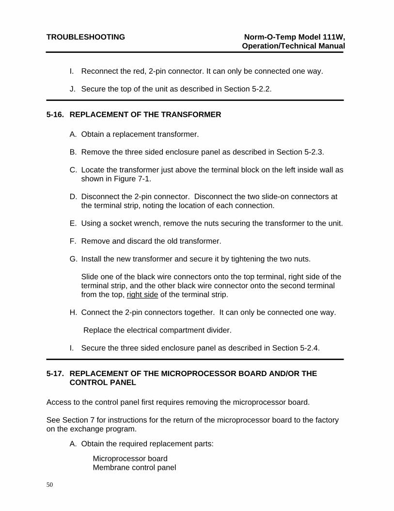
TROUBLESHOOTING Norm-O-Temp Model 111W, Operation/Technical Manual
50
I. Reconnect the red, 2-pin connector. It can only be connected one way. J. Secure the top of the unit as described in Section 5-2.2.
5-16. REPLACEMENT OF THE TRANSFORMER A. Obtain a replacement transformer. B. Remove the three sided enclosure panel as described in Section 5-2.3. C. Locate the transformer just above the terminal block on the left inside wall as
shown in Figure 7-1.
D. Disconnect the 2-pin connector. Disconnect the two slide-on connectors at the terminal strip, noting the location of each connection.
E. Using a socket wrench, remove the nuts securing the transformer to the unit. F. Remove and discard the old transformer. G. Install the new transformer and secure it by tightening the two nuts.
Slide one of the black wire connectors onto the top terminal, right side of the terminal strip, and the other black wire connector onto the second terminal from the top, right side of the terminal strip.
H. Connect the 2-pin connectors together. It can only be connected one way.
Replace the electrical compartment divider. I. Secure the three sided enclosure panel as described in Section 5-2.4.
5-17. REPLACEMENT OF THE MICROPROCESSOR BOARD AND/OR THE CONTROL PANEL
Access to the control panel first requires removing the microprocessor board. See Section 7 for instructions for the return of the microprocessor board to the factory on the exchange program.
A. Obtain the required replacement parts:
Microprocessor board Membrane control panel
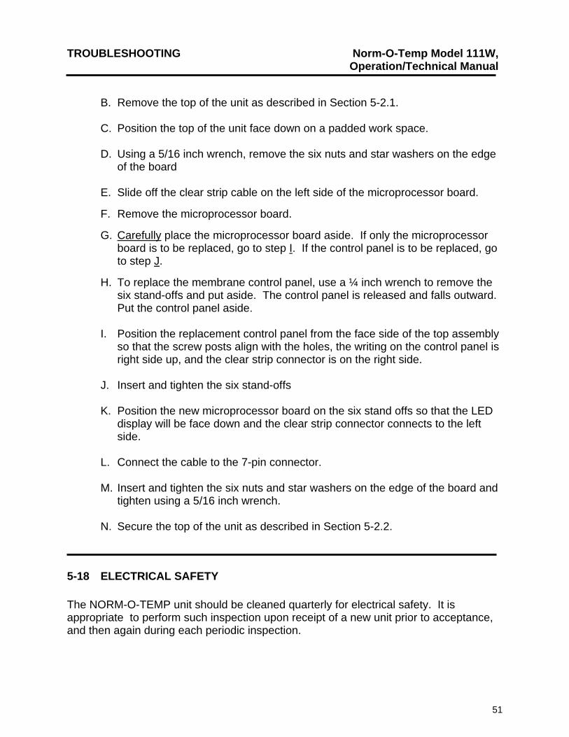
TROUBLESHOOTING Norm-O-Temp Model 111W, Operation/Technical Manual
51
B. Remove the top of the unit as described in Section 5-2.1. C. Position the top of the unit face down on a padded work space. D. Using a 5/16 inch wrench, remove the six nuts and star washers on the edge
of the board
E. Slide off the clear strip cable on the left side of the microprocessor board.
F. Remove the microprocessor board.
G. Carefully place the microprocessor board aside. If only the microprocessor board is to be replaced, go to step I. If the control panel is to be replaced, go to step J.
H. To replace the membrane control panel, use a ¼ inch wrench to remove the six stand-offs and put aside. The control panel is released and falls outward. Put the control panel aside.
I. Position the replacement control panel from the face side of the top assembly
so that the screw posts align with the holes, the writing on the control panel is right side up, and the clear strip connector is on the right side.
J. Insert and tighten the six stand-offs
K. Position the new microprocessor board on the six stand offs so that the LED
display will be face down and the clear strip connector connects to the left side.
L. Connect the cable to the 7-pin connector. M. Insert and tighten the six nuts and star washers on the edge of the board and
tighten using a 5/16 inch wrench. N. Secure the top of the unit as described in Section 5-2.2.
5-18 ELECTRICAL SAFETY The NORM-O-TEMP unit should be cleaned quarterly for electrical safety. It is appropriate to perform such inspection upon receipt of a new unit prior to acceptance, and then again during each periodic inspection.
TROUBLESHOOTING Norm-O-Temp Model 111W, Operation/Technical Manual
52
5-18.1. GROUND INTEGRITY
Using an Electrical Safety Analyzer, measure the resistance between an exposed, unpainted part of the metal case of the Norm-O-Temp and the ground conductor of the power plug. Verify that the case to ground pin resistance is less than 0.15 ohms.
5-18.2. LEAKAGE CURRENT
Using an Electrical Safety Analyzer, measure electrical leakage current of the under the following conditions: Power ON & OFF, polarity normal and reverse, unit grounded and ungrounded. The leakage current should be less than 300 microamps. If a Norm-O-Temp unit has leakage current that exceeds the appropriate limit or has a significant increase in leakage current, the cause should be investigated. Excessive leakage current is most commonly caused by a defective heater, but other components can also fail in such a way as to increase leakage current. To find the source of excessive leakage current, suspect components should be sequentially disconnected until the source of the high leakage is isolated.
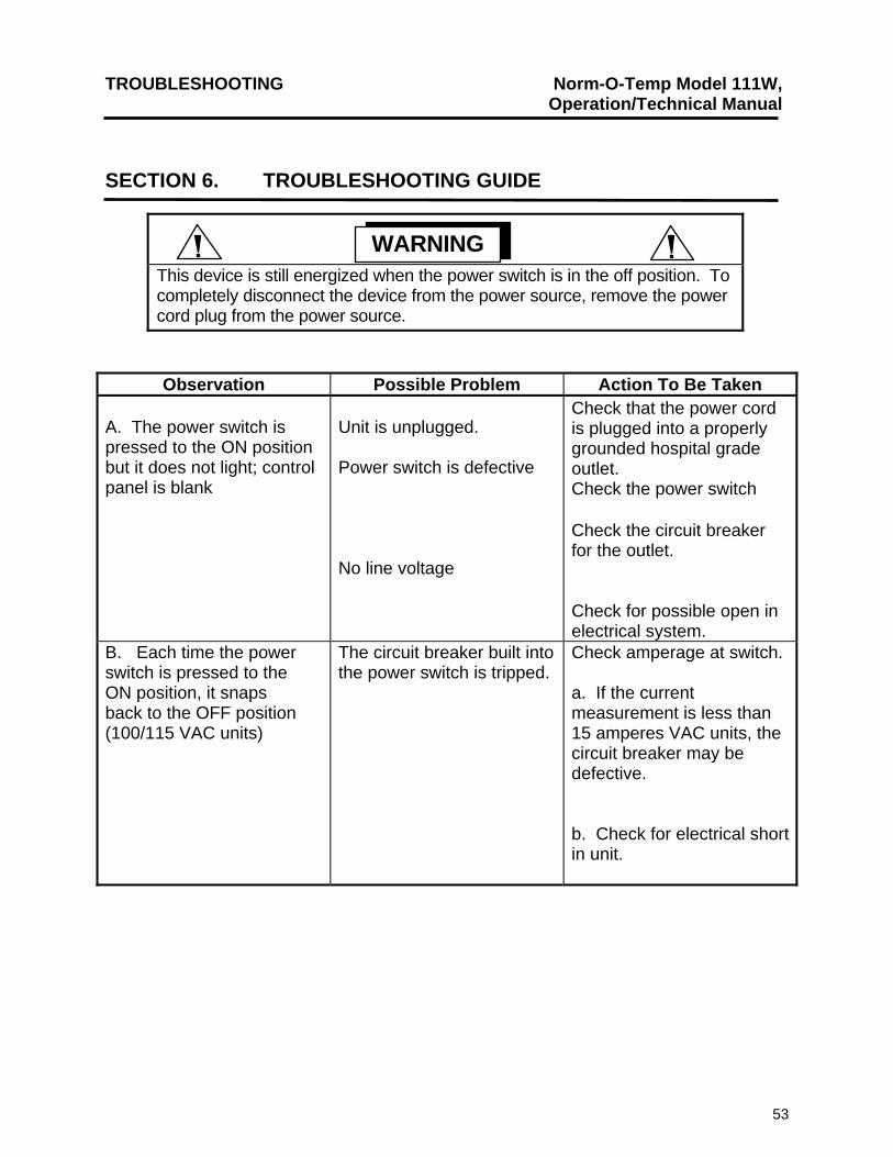
TROUBLESHOOTING Norm-O-Temp Model 111W, Operation/Technical Manual
53
SECTION 6. TROUBLESHOOTING GUIDE
WARNING
This device is still energized when the power switch is in the off position. To completely disconnect the device from the power source, remove the power cord plug from the power source.
Observation Possible Problem Action To Be Taken A. The power switch is pressed to the ON position but it does not light; control panel is blank
Unit is unplugged. Power switch is defective No line voltage
Check that the power cord is plugged into a properly grounded hospital grade outlet. Check the power switch Check the circuit breaker for the outlet. Check for possible open in electrical system.
B. Each time the power switch is pressed to the ON position, it snaps back to the OFF position (100/115 VAC units)
The circuit breaker built into the power switch is tripped.
Check amperage at switch. a. If the current measurement is less than 15 amperes VAC units, the circuit breaker may be defective. b. Check for electrical short in unit.
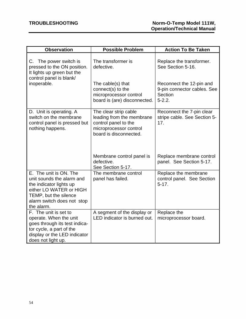
TROUBLESHOOTING Norm-O-Temp Model 111W, Operation/Technical Manual
54
Observation Possible Problem Action To Be Taken C. The power switch is pressed to the ON position. It lights up green but the control panel is blank/ inoperable.
The transformer is defective. The cable(s) that connect(s) to the microprocessor control board is (are) disconnected.
Replace the transformer. See Section 5-16. Reconnect the 12-pin and 9-pin connector cables. See Section 5-2.2.
D. Unit is operating. A switch on the membrane control panel is pressed but nothing happens.
The clear strip cable leading from the membrane control panel to the microprocessor control board is disconnected. Membrane control panel is defective. See Section 5-17.
Reconnect the 7-pin clear stripe cable. See Section 5-17. Replace membrane control panel. See Section 5-17.
E. The unit is ON. The unit sounds the alarm and the indicator lights up either LO WATER or HIGH TEMP, but the silence alarm switch does not stop the alarm.
The membrane control panel has failed.
Replace the membrane control panel. See Section 5-17.
F. The unit is set to operate. When the unit goes through its test indica- tor cycle, a part of the display or the LED indicator does not light up.
A segment of the display or LED indicator is burned out.
Replace the microprocessor board.
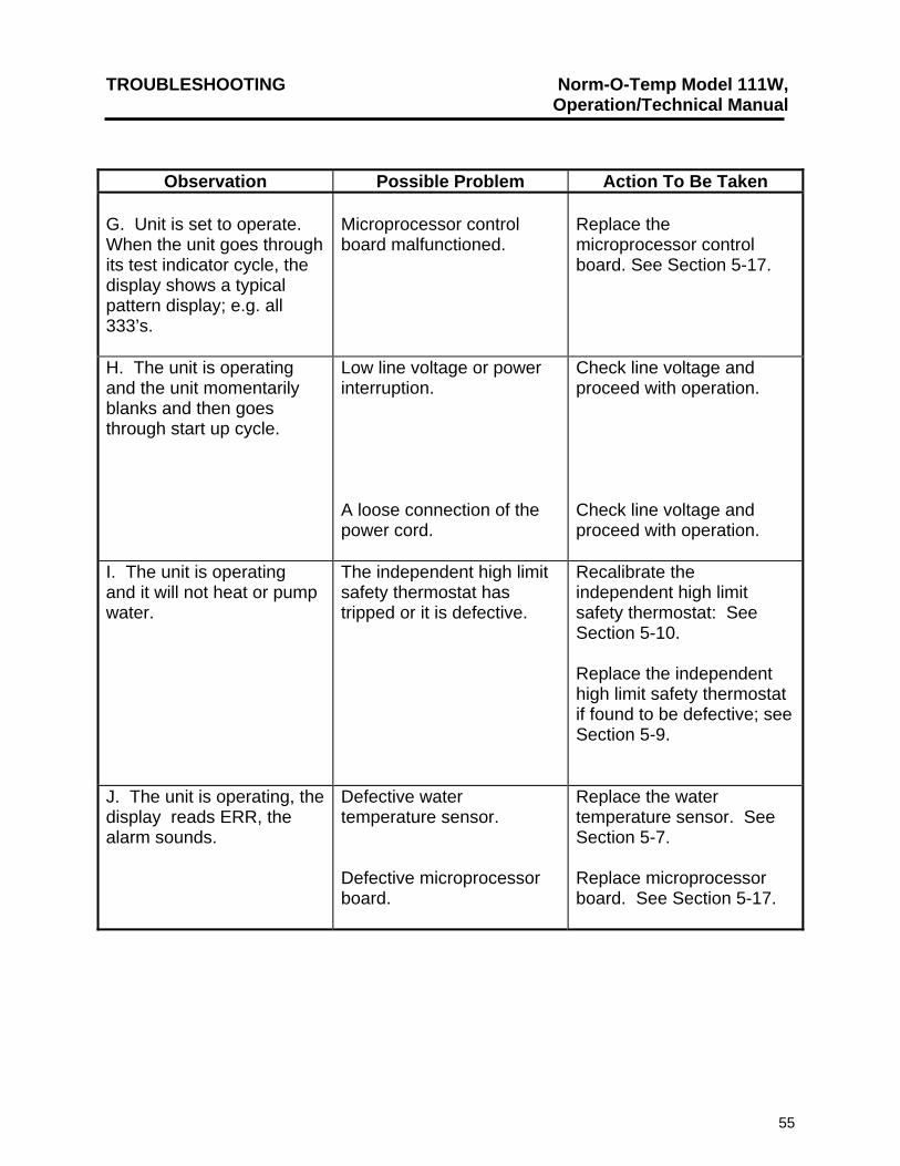
TROUBLESHOOTING Norm-O-Temp Model 111W, Operation/Technical Manual
55
Observation Possible Problem Action To Be Taken G. Unit is set to operate. When the unit goes through its test indicator cycle, the display shows a typical pattern display; e.g. all 333’s.
Microprocessor control board malfunctioned.
Replace the microprocessor control board. See Section 5-17.
H. The unit is operating and the unit momentarily blanks and then goes through start up cycle.
Low line voltage or power interruption. A loose connection of the power cord.
Check line voltage and proceed with operation. Check line voltage and proceed with operation.
I. The unit is operating and it will not heat or pump water.
The independent high limit safety thermostat has tripped or it is defective.
Recalibrate the independent high limit safety thermostat: See Section 5-10. Replace the independent high limit safety thermostat if found to be defective; see Section 5-9.
J. The unit is operating, the display reads ERR, the alarm sounds.
Defective water temperature sensor. Defective microprocessor board.
Replace the water temperature sensor. See Section 5-7. Replace microprocessor board. See Section 5-17.
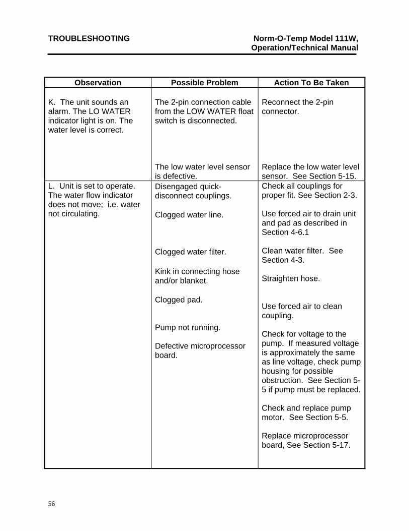
TROUBLESHOOTING Norm-O-Temp Model 111W, Operation/Technical Manual
56
Observation Possible Problem Action To Be Taken K. The unit sounds an alarm. The LO WATER indicator light is on. The water level is correct.
The 2-pin connection cable from the LOW WATER float switch is disconnected. The low water level sensor is defective.
Reconnect the 2-pin connector. Replace the low water level sensor. See Section 5-15.
L. Unit is set to operate. The water flow indicator does not move; i.e. water not circulating.
Disengaged quick-disconnect couplings.
Clogged water line.
Clogged water filter. Kink in connecting hose and/or blanket. Clogged pad. Pump not running. Defective microprocessor board.
Check all couplings for proper fit. See Section 2-3. Use forced air to drain unit and pad as described in Section 4-6.1 Clean water filter. See Section 4-3. Straighten hose. Use forced air to clean coupling. Check for voltage to the pump. If measured voltage is approximately the same as line voltage, check pump housing for possible obstruction. See Section 5-5 if pump must be replaced. Check and replace pump motor. See Section 5-5. Replace microprocessor board, See Section 5-17.
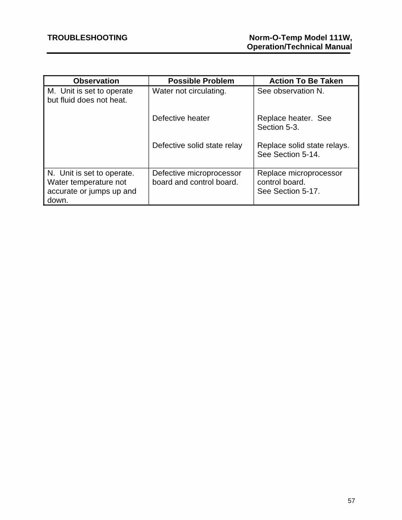
TROUBLESHOOTING Norm-O-Temp Model 111W, Operation/Technical Manual
57
Observation Possible Problem Action To Be Taken M. Unit is set to operate but fluid does not heat.
Water not circulating. Defective heater Defective solid state relay
See observation N. Replace heater. See Section 5-3. Replace solid state relays. See Section 5-14.
N. Unit is set to operate. Water temperature not accurate or jumps up and down.
Defective microprocessor board and control board.
Replace microprocessor control board. See Section 5-17.
PARTS INFORMATION Norm-O-Temp Model 111W, Operation/Technical Manual
58
SECTION 7. PARTS INFORMATION
(All Parts are rated 100/115V unless specified otherwise.)
7-1. INTRODUCTION
This section outlines information for ordering, shipping and replacing parts. Identification of parts and components are shown in Figures 7-1., 7-3. and 7-5. The numbers in Figures 7-1., 7-3. and 7-5. correspond to the numbers in the left column of the accompanying parts lists in Figure 7-2., 7-4. and 7-6. Diagrams of the functional operation of the NORM-O-TEMP are shown in Figures 7-7. and 7-9.
7-2. ORDERING INFORMATION FOR REPLACEMENT PARTS
Replacement parts are available directly from Cincinnati Sub-Zero or our authorized NORM-O-TEMP dealer. When ordering parts, specify the replacement part number listed in the second column of Figures 7-2., 7-4. and 7-6. as well as the serial number of your unit located on the specification label. There is no minimum order requirement when ordering replacement parts. Forward orders to your local dealer or to:
Cincinnati Sub-Zero Products, Inc.
12011 Mosteller Road Cincinnati, OH 45241-1528 Telephone: (513) 772-8810
Fax: (513) 772-9119
Replacement parts from the factory are shipped F.O.B., Cincinnati, Ohio. It may be desirable to stock strategic parts. Section 7-3. outlines the recommended replacement parts inventory. It is strongly recommended that all NORM-O-TEMP parts be replaced with parts purchased from Cincinnati Sub-Zero or our authorized dealers. Use of other parts could void the warranty on the unit and possibly damage the unit.
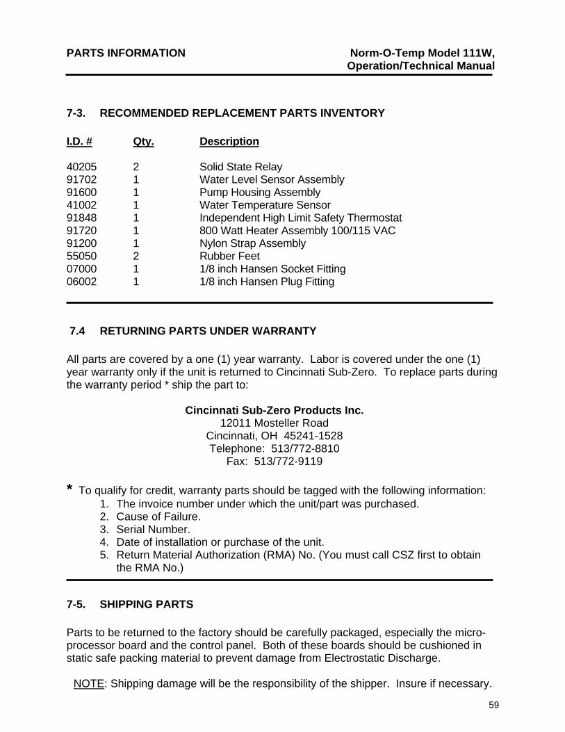
PARTS INFORMATION Norm-O-Temp Model 111W, Operation/Technical Manual
59
7-3. RECOMMENDED REPLACEMENT PARTS INVENTORY I.D. # Qty. Description 40205 2 Solid State Relay 91702 1 Water Level Sensor Assembly 91600 1 Pump Housing Assembly 41002 1 Water Temperature Sensor 91848 1 Independent High Limit Safety Thermostat 91720 1 800 Watt Heater Assembly 100/115 VAC 91200 1 Nylon Strap Assembly 55050 2 Rubber Feet 07000 1 1/8 inch Hansen Socket Fitting 06002 1 1/8 inch Hansen Plug Fitting
7.4 RETURNING PARTS UNDER WARRANTY All parts are covered by a one (1) year warranty. Labor is covered under the one (1) year warranty only if the unit is returned to Cincinnati Sub-Zero. To replace parts during the warranty period * ship the part to:
Cincinnati Sub-Zero Products Inc. 12011 Mosteller Road
Cincinnati, OH 45241-1528 Telephone: 513/772-8810
Fax: 513/772-9119
* To qualify for credit, warranty parts should be tagged with the following information: 1. The invoice number under which the unit/part was purchased. 2. Cause of Failure. 3. Serial Number. 4. Date of installation or purchase of the unit. 5. Return Material Authorization (RMA) No. (You must call CSZ first to obtain
the RMA No.)
7-5. SHIPPING PARTS
Parts to be returned to the factory should be carefully packaged, especially the micro-processor board and the control panel. Both of these boards should be cushioned in static safe packing material to prevent damage from Electrostatic Discharge.
NOTE: Shipping damage will be the responsibility of the shipper. Insure if necessary.
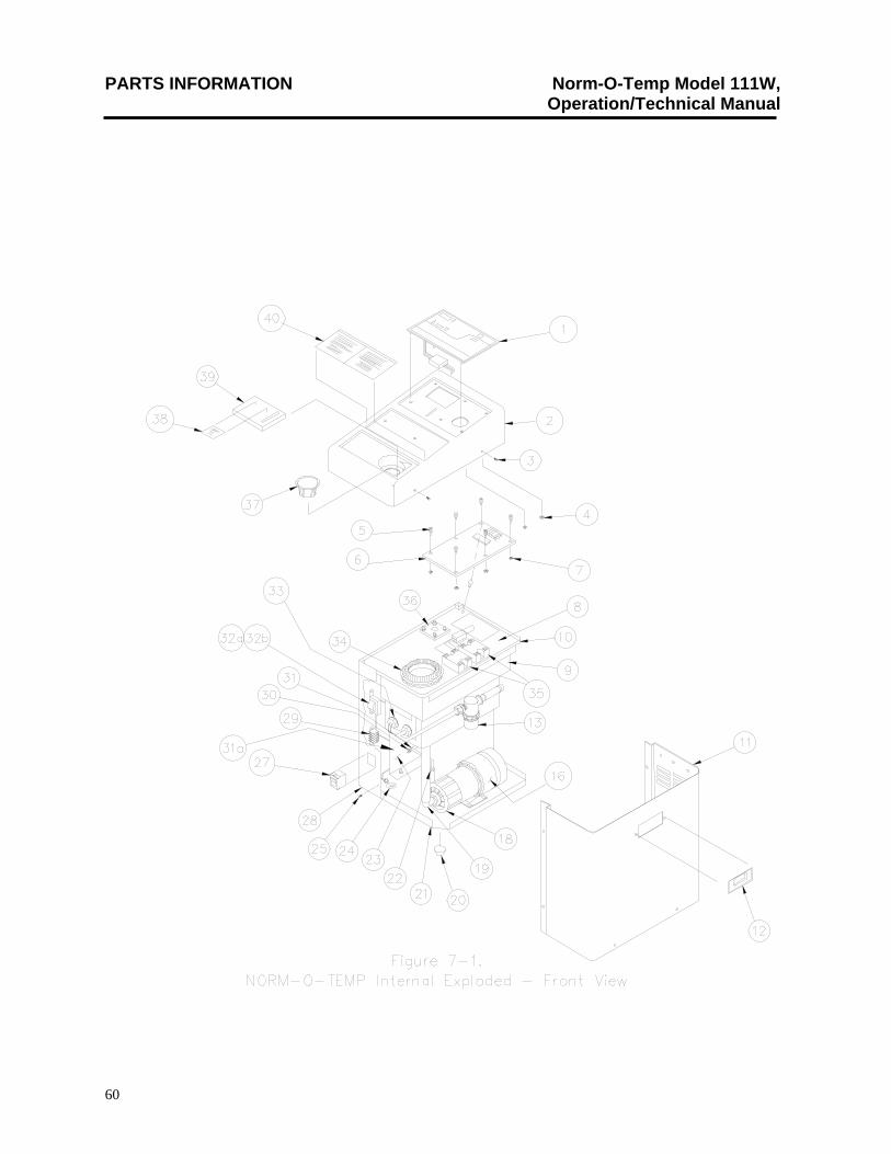
PARTS INFORMATION Norm-O-Temp Model 111W, Operation/Technical Manual
60
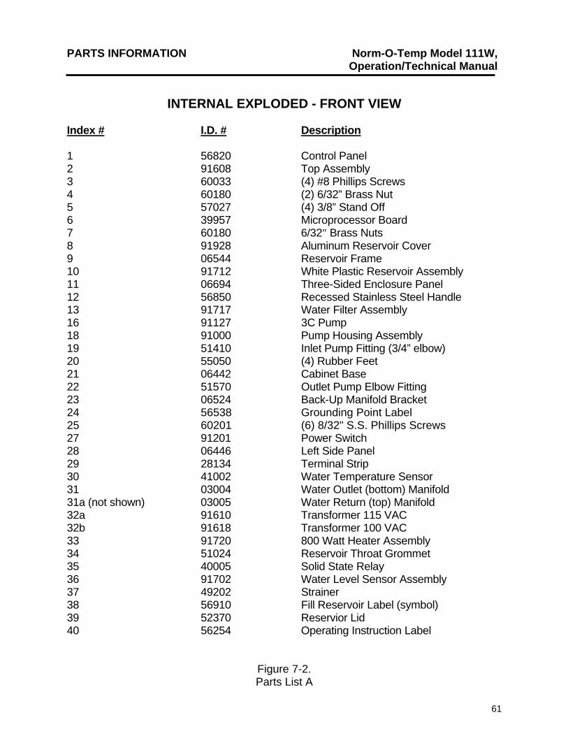
PARTS INFORMATION Norm-O-Temp Model 111W, Operation/Technical Manual
61
INTERNAL EXPLODED - FRONT VIEW Index # I.D. # Description 1 56820 Control Panel 2 91608 Top Assembly 3 60033 (4) #8 Phillips Screws 4 60180 (2) 6/32” Brass Nut 5 57027 (4) 3/8” Stand Off 6 39957 Microprocessor Board 7 60180 6/32" Brass Nuts 8 91928 Aluminum Reservoir Cover 9 06544 Reservoir Frame 10 91712 White Plastic Reservoir Assembly 11 06694 Three-Sided Enclosure Panel 12 56850 Recessed Stainless Steel Handle 13 91717 Water Filter Assembly 16 91127 3C Pump 18 91000 Pump Housing Assembly 19 51410 Inlet Pump Fitting (3/4” elbow) 20 55050 (4) Rubber Feet 21 06442 Cabinet Base 22 51570 Outlet Pump Elbow Fitting 23 06524 Back-Up Manifold Bracket 24 56538 Grounding Point Label 25 60201 (6) 8/32" S.S. Phillips Screws 27 91201 Power Switch 28 06446 Left Side Panel 29 28134 Terminal Strip 30 41002 Water Temperature Sensor 31 03004 Water Outlet (bottom) Manifold 31a (not shown) 03005 Water Return (top) Manifold 32a 91610 Transformer 115 VAC 32b 91618 Transformer 100 VAC 33 91720 800 Watt Heater Assembly 34 51024 Reservoir Throat Grommet 35 40005 Solid State Relay 36 91702 Water Level Sensor Assembly 37 49202 Strainer 38 56910 Fill Reservoir Label (symbol) 39 52370 Reservior Lid 40 56254 Operating Instruction Label
Figure 7-2. Parts List A
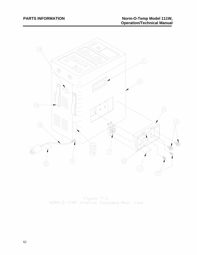
PARTS INFORMATION Norm-O-Temp Model 111W, Operation/Technical Manual
62
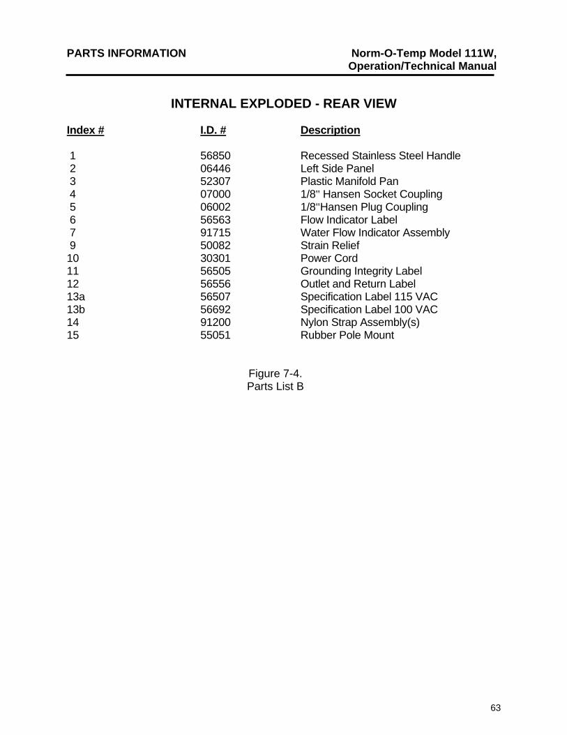
PARTS INFORMATION Norm-O-Temp Model 111W, Operation/Technical Manual
63
INTERNAL EXPLODED - REAR VIEW Index # I.D. # Description 1 56850 Recessed Stainless Steel Handle 2 06446 Left Side Panel 3 52307 Plastic Manifold Pan 4 07000 1/8" Hansen Socket Coupling 5 06002 1/8"Hansen Plug Coupling 6 56563 Flow Indicator Label 7 91715 Water Flow Indicator Assembly 9 50082 Strain Relief 10 30301 Power Cord 11 56505 Grounding Integrity Label 12 56556 Outlet and Return Label 13a 56507 Specification Label 115 VAC 13b 56692 Specification Label 100 VAC 14 91200 Nylon Strap Assembly(s) 15 55051 Rubber Pole Mount
Figure 7-4. Parts List B
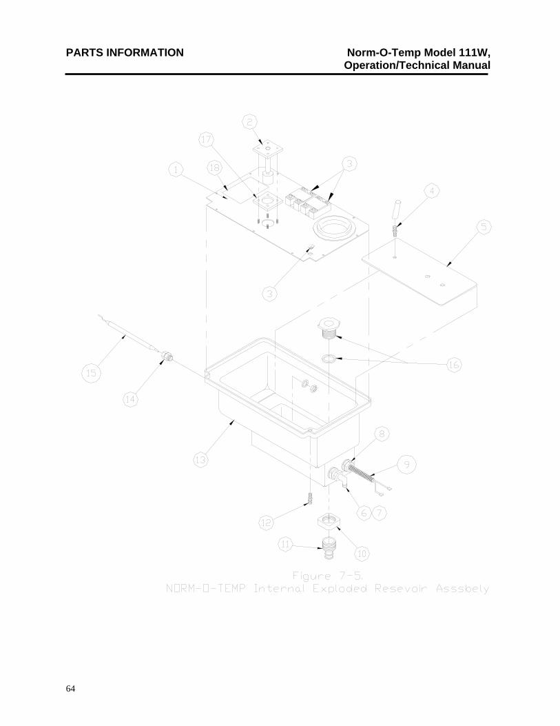
PARTS INFORMATION Norm-O-Temp Model 111W, Operation/Technical Manual
64
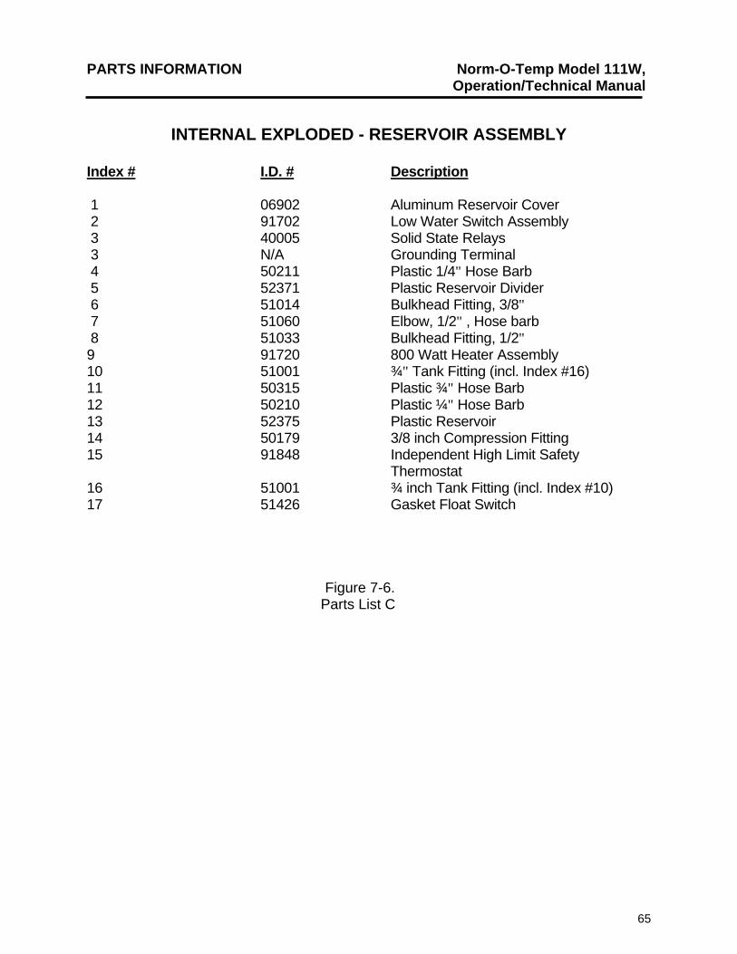
PARTS INFORMATION Norm-O-Temp Model 111W, Operation/Technical Manual
65
INTERNAL EXPLODED - RESERVOIR ASSEMBLY Index # I.D. # Description 1 06902 Aluminum Reservoir Cover 2 91702 Low Water Switch Assembly 3 40005 Solid State Relays 3 N/A Grounding Terminal 4 50211 Plastic 1/4" Hose Barb 5 52371 Plastic Reservoir Divider 6 51014 Bulkhead Fitting, 3/8" 7 51060 Elbow, 1/2" , Hose barb 8 51033 Bulkhead Fitting, 1/2" 9 91720 800 Watt Heater Assembly 10 51001 ¾" Tank Fitting (incl. Index #16) 11 50315 Plastic ¾" Hose Barb 12 50210 Plastic ¼" Hose Barb 13 52375 Plastic Reservoir 14 50179 3/8 inch Compression Fitting 15 91848 Independent High Limit Safety Thermostat 16 51001 ¾ inch Tank Fitting (incl. Index #10) 17 51426 Gasket Float Switch
Figure 7-6. Parts List C
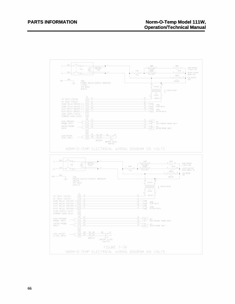
PARTS INFORMATION Norm-O-Temp Model 111W, Operation/Technical Manual
66
PARTS INFORMATION Norm-O-Temp Model 111W, Operation/Technical Manual
66
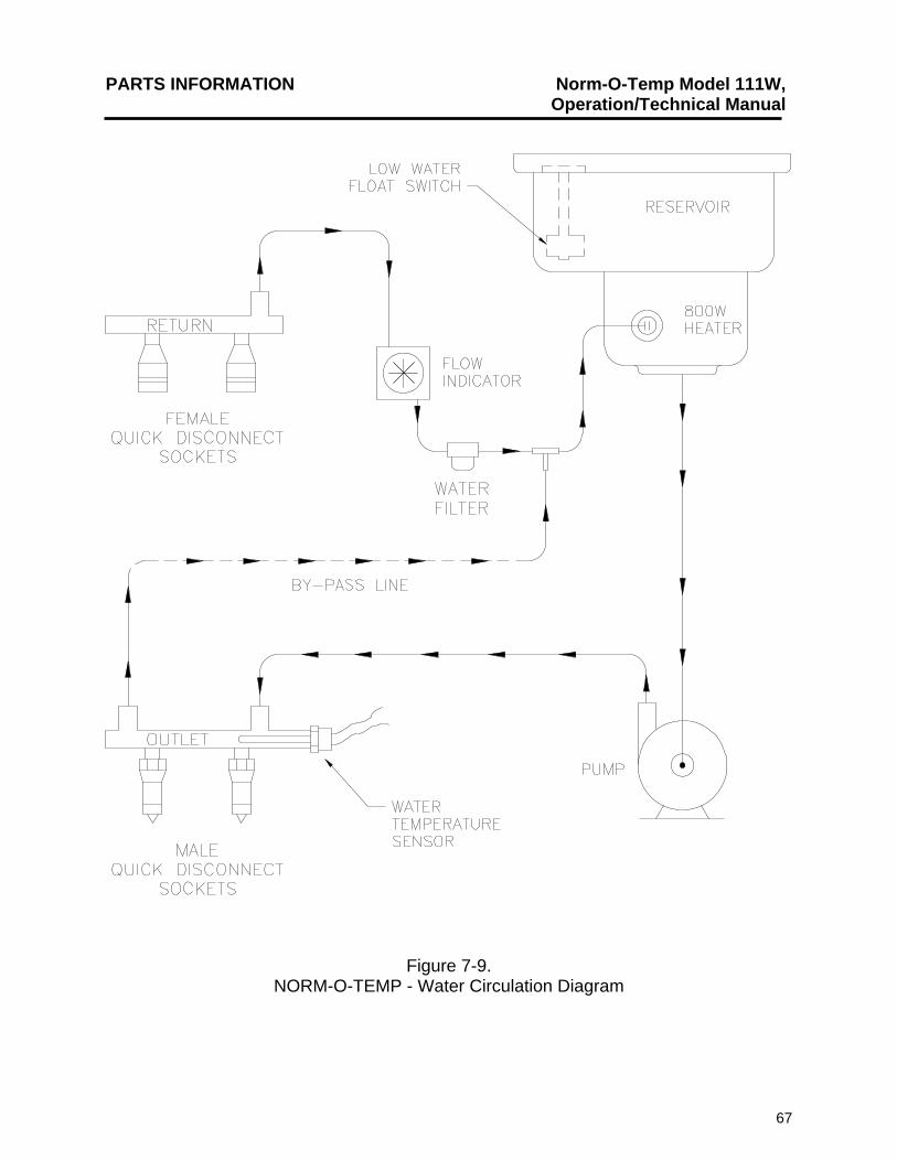
PARTS INFORMATION Norm-O-Temp Model 111W, Operation/Technical Manual
67
Figure 7-9. NORM-O-TEMP - Water Circulation Diagram
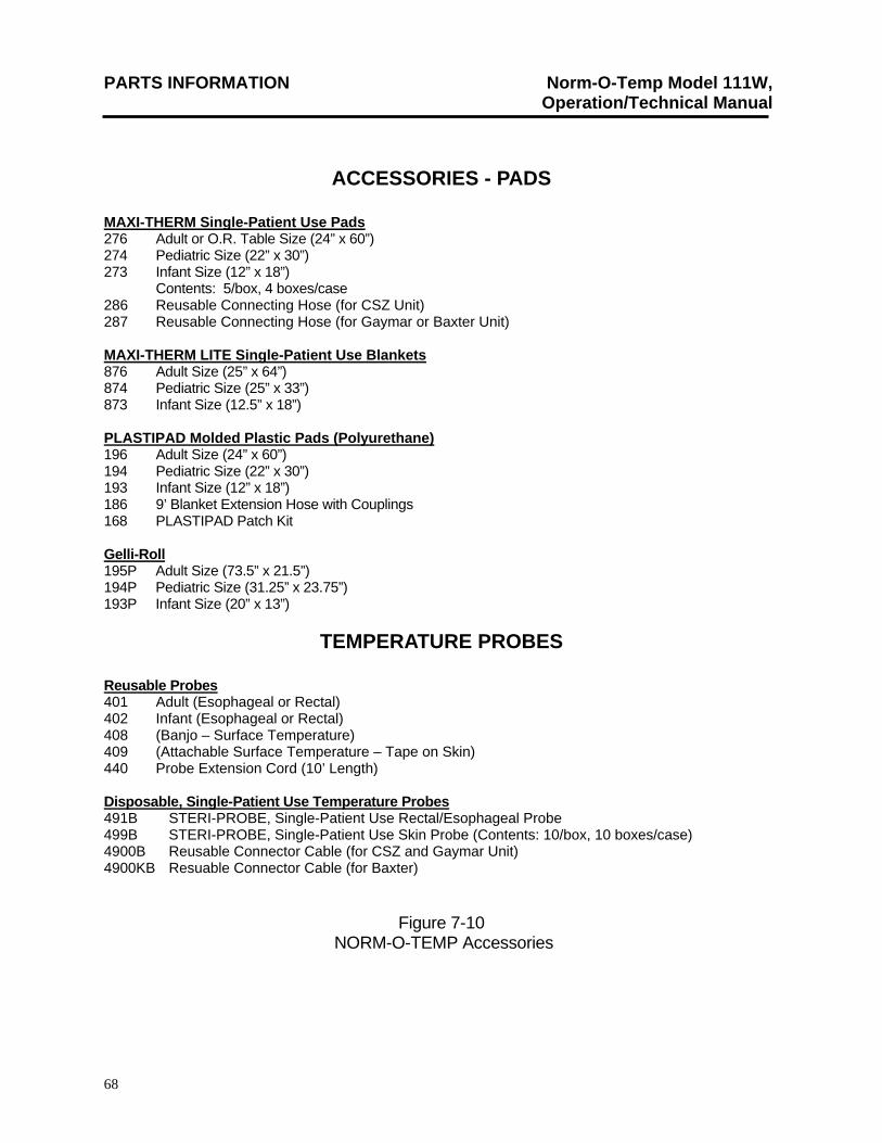
PARTS INFORMATION Norm-O-Temp Model 111W, Operation/Technical Manual
68
ACCESSORIES - PADS MAXI-THERM Single-Patient Use Pads 276 Adult or O.R. Table Size (24” x 60”) 274 Pediatric Size (22” x 30”) 273 Infant Size (12” x 18”) Contents: 5/box, 4 boxes/case
286 Reusable Connecting Hose (for CSZ Unit) 287 Reusable Connecting Hose (for Gaymar or Baxter Unit)
MAXI-THERM LITE Single-Patient Use Blankets 876 Adult Size (25” x 64”) 874 Pediatric Size (25” x 33”) 873 Infant Size (12.5” x 18”) PLASTIPAD Molded Plastic Pads (Polyurethane) 196 Adult Size (24” x 60”) 194 Pediatric Size (22” x 30”) 193 Infant Size (12” x 18”) 186 9’ Blanket Extension Hose with Couplings 168 PLASTIPAD Patch Kit Gelli-Roll 195P Adult Size (73.5” x 21.5”) 194P Pediatric Size (31.25” x 23.75”) 193P Infant Size (20” x 13”)
TEMPERATURE PROBES Reusable Probes 401 Adult (Esophageal or Rectal) 402 Infant (Esophageal or Rectal) 408 (Banjo – Surface Temperature) 409 (Attachable Surface Temperature – Tape on Skin) 440 Probe Extension Cord (10’ Length) Disposable, Single-Patient Use Temperature Probes 491B STERI-PROBE, Single-Patient Use Rectal/Esophageal Probe 499B STERI-PROBE, Single-Patient Use Skin Probe (Contents: 10/box, 10 boxes/case) 4900B Reusable Connector Cable (for CSZ and Gaymar Unit) 4900KB Resuable Connector Cable (for Baxter)
Figure 7-10 NORM-O-TEMP Accessories

69
Cincinnati Sub-Zero Products, Inc. 12011 Mosteller Road Cincinnati, OH 45241
Telephone: (513) 772-8810 Fax: (513) 772-9119 E-Mail: [email protected]