Embed Size (px)
Citation preview
Operation and Safety Manual
ANSI
Original Instructions - Keep this manual with the machine at all times.
Model(s)1932RS/6RS3248RS/10RS
3121272June 29, 2018 - Rev F
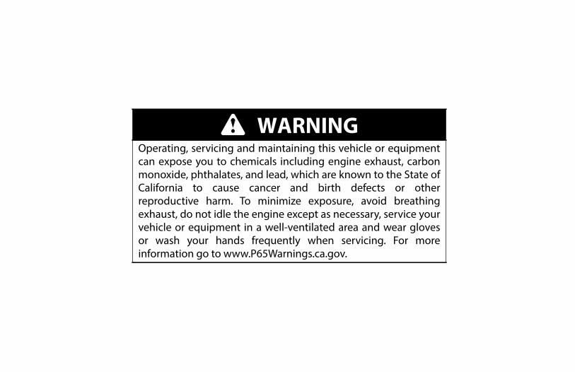
WARNINGOperating, servicing and maintaining this vehicle or equipmentcan expose you to chemicals including engine exhaust, carbonmonoxide, phthalates, and lead, which are known to the State ofCalifornia to cause cancer and birth defects or otherreproductive harm. To minimize exposure, avoid breathingexhaust, do not idle the engine except as necessary, service yourvehicle or equipment in a well-ventilated area and wear glovesor wash your hands frequently when servicing. For moreinformation go to www.P65Warnings.ca.gov.
SECTION - FOREWORD
FOREWORD
This manual is a very important tool! Keep it with the machine at all times.
The purpose of this manual is to provide owners, users, operators, lessors, and lessees with the precautions and operating proce-dures essential for the safe and proper machine operation for its intended purpose.
Due to continuous product improvements, JLG Industries, Inc. reserves the right to make specification changes without prior noti-fication. Contact JLG Industries, Inc. for updated information.
3121272 – JLG Lift – 1
SECTION - SAFETY ALERT SYMBOLS AND SAFETY SIGNAL WORDS
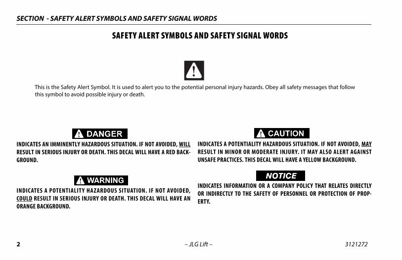
SAFETY ALERT SYMBOLS AND SAFETY SIGNAL WORDS
INDICATES AN IMMINENTLY HAZARDOUS SITUATION. IF NOT AVOIDED, WILLRESULT IN SERIOUS INJURY OR DEATH. THIS DECAL WILL HAVE A RED BACK-GROUND.
INDICATES A POTENTIALIT Y HAZARDOUS SITUATION. IF NOT AVOIDED,COULD RESULT IN SERIOUS INJURY OR DEATH. THIS DECAL WILL HAVE ANORANGE BACKGROUND.
INDICATES A POTENTIALITY HAZARDOUS SITUATION. IF NOT AVOIDED, MAYRESULT IN MINOR OR MODERATE INJURY. IT MAY ALSO ALERT AGAINSTUNSAFE PRACTICES. THIS DECAL WILL HAVE A YELLOW BACKGROUND.
NOTICEINDICATES INFORMATION OR A COMPANY POLICY THAT RELATES DIRECTLYOR INDIRECTLY TO THE SAFETY OF PERSONNEL OR PROTECTION OF PROP-ERTY.
This is the Safety Alert Symbol. It is used to alert you to the potential personal injury hazards. Obey all safety messages that followthis symbol to avoid possible injury or death.
2 – JLG Lift – 3121272
SECTION - SAFETY ALERT SYMBOLS AND SAFETY SIGNAL WORDS
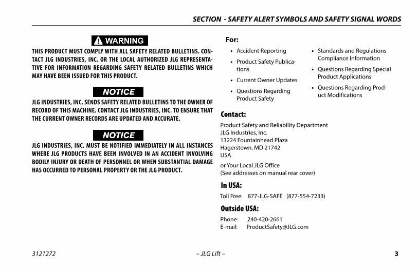
THIS PRODUCT MUST COMPLY WITH ALL SAFETY RELATED BULLETINS. CON-TACT JLG INDUSTRIES, INC. OR THE LOCAL AUTHORIZED JLG REPRESENTA-TIVE FOR INFORMATION REGARDING SAFETY RELATED BULLETINS WHICHMAY HAVE BEEN ISSUED FOR THIS PRODUCT.
NOTICEJLG INDUSTRIES, INC. SENDS SAFETY RELATED BULLETINS TO THE OWNER OFRECORD OF THIS MACHINE. CONTACT JLG INDUSTRIES, INC. TO ENSURE THATTHE CURRENT OWNER RECORDS ARE UPDATED AND ACCURATE.
NOTICEJLG INDUSTRIES, INC. MUST BE NOTIFIED IMMEDIATELY IN ALL INSTANCESWHERE JLG PRODUCTS HAVE BEEN INVOLVED IN AN ACCIDENT INVOLVINGBODILY INJURY OR DEATH OF PERSONNEL OR WHEN SUBSTANTIAL DAMAGEHAS OCCURRED TO PERSONAL PROPERTY OR THE JLG PRODUCT.
Contact:Product Safety and Reliability DepartmentJLG Industries, Inc.13224 Fountainhead PlazaHagerstown, MD 21742USA
or Your Local JLG Office(See addresses on manual rear cover)
In USA:Toll Free: 877-JLG-SAFE (877-554-7233)
Outside USA:Phone: 240-420-2661E-mail: [email protected]
For:• Accident Reporting
• Product Safety Publica-tions
• Current Owner Updates
• Questions Regarding Product Safety
• Standards and Regulations Compliance Information
• Questions Regarding Special Product Applications
• Questions Regarding Prod-uct Modifications
3121272 – JLG Lift – 3
SECTION - REVISION LOG
REVISION LOG
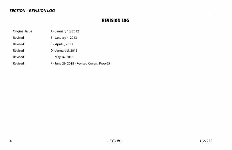
Original Issue A - January 10, 2012
Revised B - January 4, 2013
Revised C - April 8, 2013
Revised D - January 5, 2015
Revised E - May 26, 2016
Revised F - June 29, 2018 - Revised Covers, Prop 65
4 – JLG Lift – 3121272
TABLE OF CONTENTS
SECTION - PARAGRAPH, SUBJECT PAGE SECTION - PARAGRAPH, SUBJECT PAGE
FOREWORD. . . . . . . . . . . . . . . . . . . . . . . . . . . . . . . . . . . . . . . . . . . . . . . ASAFETY ALERT SYMBOLS AND SAFETY SIGNAL WORDS . . . . . B
Contact: . . . . . . . . . . . . . . . . . . . . . . . . . . . . . . . . . . . . . . . . . . . . . . . . CIn USA: . . . . . . . . . . . . . . . . . . . . . . . . . . . . . . . . . . . . . . . . . . . . . . . . . COutside USA:. . . . . . . . . . . . . . . . . . . . . . . . . . . . . . . . . . . . . . . . . . . . C
REVISION LOG . . . . . . . . . . . . . . . . . . . . . . . . . . . . . . . . . . . . . . . . . . . . D
SECTION - 1 - SAFETY PRECAUTIONS
1.1 GENERAL . . . . . . . . . . . . . . . . . . . . . . . . . . . . . . . . . . . . . . . . . . . . . . . .1-11.2 PRE-OPERATION . . . . . . . . . . . . . . . . . . . . . . . . . . . . . . . . . . . . . . . . .1-2
Operator Training and Knowledge. . . . . . . . . . . . . . . . . . . . . .1-2Workplace Inspection . . . . . . . . . . . . . . . . . . . . . . . . . . . . . . . . . .1-2Machine Inspection . . . . . . . . . . . . . . . . . . . . . . . . . . . . . . . . . . . .1-3
1.3 OPERATION. . . . . . . . . . . . . . . . . . . . . . . . . . . . . . . . . . . . . . . . . . . . . .1-4General . . . . . . . . . . . . . . . . . . . . . . . . . . . . . . . . . . . . . . . . . . . . . . . .1-4Trip and Fall Hazards . . . . . . . . . . . . . . . . . . . . . . . . . . . . . . . . . . .1-5Electrocution Hazards . . . . . . . . . . . . . . . . . . . . . . . . . . . . . . . . . .1-6Tipping Hazards . . . . . . . . . . . . . . . . . . . . . . . . . . . . . . . . . . . . . . .1-7Crushing and Collision Hazards . . . . . . . . . . . . . . . . . . . . . . . . .1-9
1.4 TOWING, LIFTING, AND HAULING. . . . . . . . . . . . . . . . . . . . . . . 1-111.5 MAINTENANCE . . . . . . . . . . . . . . . . . . . . . . . . . . . . . . . . . . . . . . . . 1-11
Maintenance Hazards . . . . . . . . . . . . . . . . . . . . . . . . . . . . . . . . 1-11Battery Hazards . . . . . . . . . . . . . . . . . . . . . . . . . . . . . . . . . . . . . . 1-12
SECTION - 2 - USER RESPONSIBILITIES, MACHINE PREPARATION AND INSPECTION
2.1 PERSONNEL TRAINING . . . . . . . . . . . . . . . . . . . . . . . . . . . . . . . . . . .2-1Operator Training. . . . . . . . . . . . . . . . . . . . . . . . . . . . . . . . . . . . . .2-1Training Supervision . . . . . . . . . . . . . . . . . . . . . . . . . . . . . . . . . . .2-2Operator Responsibility . . . . . . . . . . . . . . . . . . . . . . . . . . . . . . . .2-2
2.2 PREPARATION, INSPECTION, AND MAINTENANCE . . . . . . . . .2-22.3 PRE-START INSPECTION . . . . . . . . . . . . . . . . . . . . . . . . . . . . . . . . . .2-42.4 DAILY WALK-AROUND INSPECTION . . . . . . . . . . . . . . . . . . . . . .2-62.5 FUNCTION CHECK . . . . . . . . . . . . . . . . . . . . . . . . . . . . . . . . . . . . . . .2-8
SECTION - 3 - MACHINE CONTROLS, INDICATORS AND OPERATION
3.1 GENERAL . . . . . . . . . . . . . . . . . . . . . . . . . . . . . . . . . . . . . . . . . . . . . . . .3-13.2 DESCRIPTION . . . . . . . . . . . . . . . . . . . . . . . . . . . . . . . . . . . . . . . . . . . .3-13.3 OPERATING CHARACTERISTICS/LIMITATIONS . . . . . . . . . . . . .3-2
General . . . . . . . . . . . . . . . . . . . . . . . . . . . . . . . . . . . . . . . . . . . . . . . .3-2Placards . . . . . . . . . . . . . . . . . . . . . . . . . . . . . . . . . . . . . . . . . . . . . . .3-2
3.4 PLATFORM LOADING . . . . . . . . . . . . . . . . . . . . . . . . . . . . . . . . . . . .3-23.5 MACHINE CONTROL LOCATIONS . . . . . . . . . . . . . . . . . . . . . . . . .3-33.6 GROUND CONTROL STATION. . . . . . . . . . . . . . . . . . . . . . . . . . . . .3-5
Ground Emergency Stop Switch . . . . . . . . . . . . . . . . . . . . . . . .3-6Key Selector Switch . . . . . . . . . . . . . . . . . . . . . . . . . . . . . . . . . . . .3-6Platform Lift/Lower Switch . . . . . . . . . . . . . . . . . . . . . . . . . . . . .3-6
3121221 – JLG Lift – i
TABLE OF CONTENTS
SECTION - PARAGRAPH, SUBJECT PAGE SECTION - PARAGRAPH, SUBJECT PAGE
MDI-Indicator. . . . . . . . . . . . . . . . . . . . . . . . . . . . . . . . . . . . . . . . . . 3-6Overload Indicator (If Equipped) . . . . . . . . . . . . . . . . . . . . . . . 3-7
3.7 PLATFORM CONTROL STATION. . . . . . . . . . . . . . . . . . . . . . . . . . . 3-9Platform Emergency Stop Switch. . . . . . . . . . . . . . . . . . . . . .3-10Lift/Drive Select. . . . . . . . . . . . . . . . . . . . . . . . . . . . . . . . . . . . . . .3-10Forward/Reverse/Lift/Lower Direction Decal. . . . . . . . . . .3-10Drive/Lift/Steer Joystick Control . . . . . . . . . . . . . . . . . . . . . . .3-11Steering And Traveling. . . . . . . . . . . . . . . . . . . . . . . . . . . . . . . .3-12Steering . . . . . . . . . . . . . . . . . . . . . . . . . . . . . . . . . . . . . . . . . . . . . .3-12Traveling Forward and Reverse. . . . . . . . . . . . . . . . . . . . . . . .3-12Raising And Lowering Platform. . . . . . . . . . . . . . . . . . . . . . . .3-14Arm Guards . . . . . . . . . . . . . . . . . . . . . . . . . . . . . . . . . . . . . . . . . .3-14Overload Indicator (If Equipped) . . . . . . . . . . . . . . . . . . . . . .3-14Tilt Indicator Warning Light and Alarm . . . . . . . . . . . . . . . .3-15Horn . . . . . . . . . . . . . . . . . . . . . . . . . . . . . . . . . . . . . . . . . . . . . . . . .3-15Low Battery Charge and System Fault Indicator . . . . . . . .3-15Alarm . . . . . . . . . . . . . . . . . . . . . . . . . . . . . . . . . . . . . . . . . . . . . . . .3-15
3.8 PLATFORM EXTENSION . . . . . . . . . . . . . . . . . . . . . . . . . . . . . . . . .3-163.9 PLATFORM RAILS - FOLD-DOWN PROCEDURE - (3248RS/10RS
AND 6RS-CE ONLY) . . . . . . . . . . . . . . . . . . . . . . . . . . . . . . . . . . . . .3-173.10 BATTERY CHARGING . . . . . . . . . . . . . . . . . . . . . . . . . . . . . . . . . . . .3-20
Battery Charger Fault (LED Flash) . . . . . . . . . . . . . . . . . . . . . .3-213.11 DC TO AC INVERTER OPERATION (OPTION) . . . . . . . . . . . . . .3-223.12 PARKING AND STOWING MACHINE. . . . . . . . . . . . . . . . . . . . . .3-23
3.13 SCISSOR ARM - SAFETY PROP . . . . . . . . . . . . . . . . . . . . . . . . . . .3-243.14 MACHINE LIFTING AND TIE DOWN . . . . . . . . . . . . . . . . . . . . . .3-26
Lifting . . . . . . . . . . . . . . . . . . . . . . . . . . . . . . . . . . . . . . . . . . . . . . . .3-26Tie Down . . . . . . . . . . . . . . . . . . . . . . . . . . . . . . . . . . . . . . . . . . . . .3-26
3.15 TOWING. . . . . . . . . . . . . . . . . . . . . . . . . . . . . . . . . . . . . . . . . . . . . . . .3-29Electric Brake Release . . . . . . . . . . . . . . . . . . . . . . . . . . . . . . . . .3-29Mechanical Brake Release . . . . . . . . . . . . . . . . . . . . . . . . . . . . .3-30
SECTION - 4 - EMERGENCY PROCEDURES
4.1 GENERAL INFORMATION. . . . . . . . . . . . . . . . . . . . . . . . . . . . . . . . . 4-14.2 EMERGENCY OPERATION . . . . . . . . . . . . . . . . . . . . . . . . . . . . . . . . 4-1
Operator Unable to Control Machine . . . . . . . . . . . . . . . . . . . 4-1Platform Caught Overhead. . . . . . . . . . . . . . . . . . . . . . . . . . . . . 4-1Righting of Tipped Machine. . . . . . . . . . . . . . . . . . . . . . . . . . . . 4-1
4.3 PLATFORM MANUAL DESCENT. . . . . . . . . . . . . . . . . . . . . . . . . . . 4-14.4 INCIDENT NOTIFICATION . . . . . . . . . . . . . . . . . . . . . . . . . . . . . . . . 4-2
SECTION - 5 - GENERAL SPECIFICATIONS AND MAINTENANCE
5.1 INTRODUCTION . . . . . . . . . . . . . . . . . . . . . . . . . . . . . . . . . . . . . . . . . 5-1Other Publications Available:. . . . . . . . . . . . . . . . . . . . . . . . . . . 5-1
5.2 OPERATING SPECIFICATIONS. . . . . . . . . . . . . . . . . . . . . . . . . . . . . 5-2Platform Capacities . . . . . . . . . . . . . . . . . . . . . . . . . . . . . . . . . . . . 5-3Machine Dimensional Data . . . . . . . . . . . . . . . . . . . . . . . . . . . . 5-4Tires. . . . . . . . . . . . . . . . . . . . . . . . . . . . . . . . . . . . . . . . . . . . . . . . . . . 5-5
ii – JLG Lift – 3121221
TABLE OF CONTENTS
SECTION - PARAGRAPH, SUBJECT PAGE SECTION - PARAGRAPH, SUBJECT PAGE
Batteries . . . . . . . . . . . . . . . . . . . . . . . . . . . . . . . . . . . . . . . . . . . . . . .5-5Electrical System . . . . . . . . . . . . . . . . . . . . . . . . . . . . . . . . . . . . . . .5-5
5.3 CRITICAL STABILITY WEIGHTS . . . . . . . . . . . . . . . . . . . . . . . . . . . .5-65.4 LUBRICATION . . . . . . . . . . . . . . . . . . . . . . . . . . . . . . . . . . . . . . . . . . . .5-6
Lubrication Capacities. . . . . . . . . . . . . . . . . . . . . . . . . . . . . . . . . .5-6Hydraulic Oil . . . . . . . . . . . . . . . . . . . . . . . . . . . . . . . . . . . . . . . . . . .5-6Lubrication Specifications . . . . . . . . . . . . . . . . . . . . . . . . . . . . . .5-7
5.5 MAINTENANCE . . . . . . . . . . . . . . . . . . . . . . . . . . . . . . . . . . . . . . . . . .5-8 Hydraulic Oil Check Procedure . . . . . . . . . . . . . . . . . . . . . . . . .5-8
5.6 BATTERY MAINTENANCE . . . . . . . . . . . . . . . . . . . . . . . . . . . . . . . . .5-9Battery Maintenance and Safety Practices. . . . . . . . . . . . . . .5-9Battery Quick-Disconnect - (If Equipped) . . . . . . . . . . . . . . . .5-9
5.7 TIRES AND WHEELS . . . . . . . . . . . . . . . . . . . . . . . . . . . . . . . . . . . . 5-10Tire Wear and Damage . . . . . . . . . . . . . . . . . . . . . . . . . . . . . . . 5-10Wheel and Tire Replacement . . . . . . . . . . . . . . . . . . . . . . . . . 5-10Wheel Installation. . . . . . . . . . . . . . . . . . . . . . . . . . . . . . . . . . . . 5-11
5.8 SUPPLEMENTAL INFORMATION . . . . . . . . . . . . . . . . . . . . . . . . 5-125.9 DECAL INSTALLATION. . . . . . . . . . . . . . . . . . . . . . . . . . . . . . . . . . 5-135.10 DIAGNOSTIC TROUBLE CODES (DTC). . . . . . . . . . . . . . . . . . . . 5-175.11 DTC CHECK TABLE INDEX . . . . . . . . . . . . . . . . . . . . . . . . . . . . . . 5-175.12 DIAGNOSTIC TROUBLE CODES (DTC)
CHECK TABLES. . . . . . . . . . . . . . . . . . . . . . . . . . . . . . . . . . . . . . . . . 5-180-0 Help Comments . . . . . . . . . . . . . . . . . . . . . . . . . . . . . . . . . . 5-182-1 Power-Up . . . . . . . . . . . . . . . . . . . . . . . . . . . . . . . . . . . . . . . . 5-19
2-2 Platform Controls . . . . . . . . . . . . . . . . . . . . . . . . . . . . . . . . 5-192-3 Ground Controls . . . . . . . . . . . . . . . . . . . . . . . . . . . . . . . . . 5-202-5 Function Prevented . . . . . . . . . . . . . . . . . . . . . . . . . . . . . . 5-213-1 Line Contactor Open Circuit . . . . . . . . . . . . . . . . . . . . . . 5-223-2 Line Contactor Short Circuit . . . . . . . . . . . . . . . . . . . . . . 5-223-3 Ground Output Driver . . . . . . . . . . . . . . . . . . . . . . . . . . . . 5-224-2 Thermal Limit (SOA) . . . . . . . . . . . . . . . . . . . . . . . . . . . . . . 5-254-4 Battery Supply . . . . . . . . . . . . . . . . . . . . . . . . . . . . . . . . . . . 5-256-6 Communication. . . . . . . . . . . . . . . . . . . . . . . . . . . . . . . . . . 5-267-7 Electric Motor . . . . . . . . . . . . . . . . . . . . . . . . . . . . . . . . . . . . 5-268-2 LSS - Load Sensing System. . . . . . . . . . . . . . . . . . . . . . . . 5-278-4 Elevation Switch . . . . . . . . . . . . . . . . . . . . . . . . . . . . . . . . . 5-289-9 Hardware . . . . . . . . . . . . . . . . . . . . . . . . . . . . . . . . . . . . . . . . 5-29
SECTION - 6 - INSPECTION AND REPAIR LOG
LIST OF FIGURES
2-1. Daily Walk-Around Inspection - All Machines . . . . . . . . . .2-72-2. Machine Limit Switch Location . . . . . . . . . . . . . . . . . . . . . . .2-93-1. 1932RS/6RS - Location of Machine Controls.. . . . . . . . . . .3-33-2. 3248RS/10RS - Location of Machine Controls. . . . . . . . . .3-43-3. Ground Control Station. . . . . . . . . . . . . . . . . . . . . . . . . . . . . . .3-53-4. MDI Indicator . . . . . . . . . . . . . . . . . . . . . . . . . . . . . . . . . . . . . . . .3-73-5. Location of Manual Descent Control . . . . . . . . . . . . . . . . . .3-83-6. Platform Control Station. . . . . . . . . . . . . . . . . . . . . . . . . . . . . .3-9
3121221 – JLG Lift – iii
TABLE OF CONTENTS
SECTION - PARAGRAPH, SUBJECT PAGE SECTION - PARAGRAPH, SUBJECT PAGE
3-7. Platform Control Components . . . . . . . . . . . . . . . . . . . . . . .3-113-8. Grade and Sideslope Definition . . . . . . . . . . . . . . . . . . . . . .3-133-9. Platform Deck Extension . . . . . . . . . . . . . . . . . . . . . . . . . . . .3-163-10. Platform Rails - Fold Down Sequence -
3248RS/10RS Only . . . . . . . . . . . . . . . . . . . . . . . . . . . . . . . . . .3-183-11. Platform Rails - Fold Down Sequence -
6RS (CE Only) . . . . . . . . . . . . . . . . . . . . . . . . . . . . . . . . . . . . . . .3-193-12. Charger Decal LED Indicators . . . . . . . . . . . . . . . . . . . . . . . .3-203-13. Location of AC Inverter ON/OFF - Toggle Switch. . . . . .3-223-14. Securing Control Station to Platform. . . . . . . . . . . . . . . . .3-233-15. 1932RS/6RS - Scissor Arm - Safety Prop . . . . . . . . . . . . . .3-253-16. 3248RS/10RS - Scissor Arm - Safety Prop . . . . . . . . . . . . .3-253-17. Fork Lift Pockets - Location . . . . . . . . . . . . . . . . . . . . . . . . . .3-263-18. Lifting Using Spreader Bar and
Lift Lug Locations - All Machines . . . . . . . . . . . . . . . . . . . . .3-273-19. Tie Down and Lift Lug Locations - All Machines. . . . . . .3-283-20. Electric Brake Release - Location - All Machines . . . . . . .3-293-21. Brake - Manual Disengage. . . . . . . . . . . . . . . . . . . . . . . . . . .3-304-1. Location of Manual Descent Control . . . . . . . . . . . . . . . . . . 4-25-1. Hydraulic Oil Check Procedure - All Machines . . . . . . . . . 5-85-2. Battery Fluid Level. . . . . . . . . . . . . . . . . . . . . . . . . . . . . . . . . . . . 5-95-3. Wheel Lug Nut Tightening Sequence . . . . . . . . . . . . . . . .5-115-4. Machine Decal Installation - All Machines . . . . . . . . . . . .5-12
LIST OF TABLES
1-1 Minimum Approach Distances (M.A.D.) . . . . . . . . . . . . . . . 1-61-2 Beaufort Scale (For Reference Only) . . . . . . . . . . . . . . . . . . . 1-82-1 Inspection and Maintenance Table. . . . . . . . . . . . . . . . . . . . 2-32-2 High Drive Cutout Height. . . . . . . . . . . . . . . . . . . . . . . . . . . . . 2-82-3 Tilt Activation Setting . . . . . . . . . . . . . . . . . . . . . . . . . . . . . . . . 2-93-1 Battery Charger Fault (LED Flash) . . . . . . . . . . . . . . . . . . . .3-215-1 Operating Specifications . . . . . . . . . . . . . . . . . . . . . . . . . . . . . 5-25-2 Capacities. . . . . . . . . . . . . . . . . . . . . . . . . . . . . . . . . . . . . . . . . . . . 5-35-3 Dimensions . . . . . . . . . . . . . . . . . . . . . . . . . . . . . . . . . . . . . . . . . . 5-45-4 Tire Specifications . . . . . . . . . . . . . . . . . . . . . . . . . . . . . . . . . . . . 5-55-5 Battery Specifications . . . . . . . . . . . . . . . . . . . . . . . . . . . . . . . . 5-55-6 Electrical System Specifications . . . . . . . . . . . . . . . . . . . . . . . 5-55-7 Critical Stability Weights. . . . . . . . . . . . . . . . . . . . . . . . . . . . . . 5-65-8 Capacities. . . . . . . . . . . . . . . . . . . . . . . . . . . . . . . . . . . . . . . . . . . . 5-65-9 Hydraulic Oil . . . . . . . . . . . . . . . . . . . . . . . . . . . . . . . . . . . . . . . . . 5-65-10 Lubrication Specifications . . . . . . . . . . . . . . . . . . . . . . . . . . . . 5-75-11 Hydraulic Oil Specifications . . . . . . . . . . . . . . . . . . . . . . . . . . . 5-75-12 Wheel Torque Chart . . . . . . . . . . . . . . . . . . . . . . . . . . . . . . . . .5-115-13 Machine Decal Installation Chart. . . . . . . . . . . . . . . . . . . . .5-136-1 Inspection and Repair Log . . . . . . . . . . . . . . . . . . . . . . . . . . . . 6-1
iv – JLG Lift – 3121221
SECTION 1 - SAFETY PRECAUTIONS
SECTION 1. SAFETY PRECAUTIONS
1.1 GENERALThis section outlines the necessary precautions for properand safe machine usage and maintenance. In order to pro-mote proper machine usage, it is mandatory that a dailyroutine is established based on the content of this manual.A maintenance program, using the information providedin this manual and the Service and Maintenance Manual,must also be established by a qualified person and mustbe followed to ensure that the machine is safe to operate.
The owner/user/operator/lessor/lessee of the machinemust not accept operating responsibility until this manualhas been read, training is accomplished, and operation ofthe machine has been completed under the supervision ofan experienced and qualified operator.
These sections contain the responsibilities of the owner,user, operator, lessor, and lessee concerning safety, train-ing, inspection, maintenance, application, and operation.Ifthere are any questions with regard to safety, training,inspection, maintenance, application, and operation,please contact JLG Industries, Inc. (“JLG”).
FAILURE TO COMPLY WITH THE SAFETY PRECAUTIONS LISTED IN THIS MAN-UAL COULD RESULT IN MACHINE DAMAGE, PROPERTY DAMAGE, PERSONALINJURY OR DEATH.
3121272 – JLG Lift – 1-1
SECTION 1 - SAFETY PRECAUTIONS
1.2 PRE-OPERATION
Operator Training and Knowledge• The Operation and Safety Manual must be read and under-
stood in its entirety before operating the machine. For clari-fication, questions, or additional information regarding anyportions of this manual, contact JLG Industries, Inc.
• An operator must not accept operating responsibilitiesuntil adequate training has been given by competent andauthorized persons.
• Allow only those authorized and qualified personnel tooperate the machine who have demonstrated that theyunderstand the safe and proper operation and mainte-nance of the unit.
• Read, understand, and obey all DANGERS, WARNINGS, CAU-TIONS, and operating instructions on the machine and inthis manual.
• Ensure that the machine is to be used in a manner which iswithin the scope of its intended application as determinedby JLG.
• All operating personnel must be familiar with the emer-gency controls and emergency operation of the machine asspecified in this manual.
• Read, understand, and obey all applicable employer, local,and governmental regulations as they pertain to your utili-zation and application of the machine.
Workplace Inspection• Precautions to avoid all hazards in the work area must be
taken by the user before and during operation of themachine.
• Do not operate or raise the platform from a position ontrucks, trailers, railway cars, floating vessels, scaffolds orother equipment unless the application is approved in writ-ing by JLG.
• Before operation, check work area for overhead hazardssuch as electric lines, bridge cranes, and other potentialoverhead obstructions.
• Check floor surfaces for holes, bumps, drop-offs, obstruc-tions, debris, concealed holes, and other potential hazards.
1-2 – JLG Lift – 3121272
SECTION 1 - SAFETY PRECAUTIONS
• Check the work area for hazardous locations. Do not oper-ate the machine in hazardous environments unlessapproved for that purpose by JLG.
• Ensure that the ground conditions are adequate to supportthe maximum tire load indicated on the tire load decalslocated on the chassis adjacent to each wheel.
• This machine can be operated in nominal ambient temper-atures of 0o F to 104o F (-20o C to 40o C). Consult JLG to opti-mize operation outside of this temperature range.
Machine Inspection• Do not operate this machine until the inspections and func-
tional checks have been performed as specified in Section 2of this manual.
• Do not operate this machine until it has been serviced andmaintained according to the maintenance and inspectionrequirements as specified in the machine’s Service andMaintenance Manual.
• Ensure all safety devices are operating properly. Modifica-tion of these devices is a safety violation.
MODIFICATION OR ALTERATION OF AN AERIAL WORK PLATFORM SHALL BEMADE ONLY WITH PRIOR WRITTEN PERMISSION FROM THE MANUFACTURER.
• Do not operate any machine on which the safety or instruc-tion placards or decals are missing or illegible.
• Check the machine for modifications to original compo-nents. Ensure that any modifications have been approvedby JLG.
• Avoid accumulation of debris on platform deck. Keep mud,oil, grease, and other slippery substances from footwearand platform deck.
1.3 OPERATION
General• Machine operation requires your full attention. Bring the
machine to a full stop before using any device, i.e. cellphones, two-way radios, etc. that will distract your attentionfrom safely operating the machine.
• Do not use the machine for any purpose other than posi-tioning personnel, their tools, and equipment.
• Before operation, the user must be familiar with themachine capabilities and operating characteristics of allfunctions.
• Never operate a malfunctioning machine. If a malfunctionoccurs, shut down the machine. Remove the unit from ser-vice and notify the proper authorities.
3121272 – JLG Lift – 1-3
SECTION 1 - SAFETY PRECAUTIONS
• Do not remove, modify, or disable any safety devices.
• Never slam a control switch or lever through neutral to anopposite direction. Always return switch to neutral and stopbefore moving the switch to the next function. Operatecontrols with slow and even pressure.
• Do not allow personnel to tamper with or operate themachine from the ground with personnel in the platform,except in an emergency.
• Do not carry materials directly on platform railing unlessapproved by JLG.
• When two or more persons are in the platform, the operatorshall be responsible for all machine operations.
• Always ensure that power tools are properly stowed andnever left hanging by their cord from the platform workarea.
• Do not assist a stuck or disabled machine by pushing orpulling except by pulling at the chassis tie-down lugs.
• Fully lower platform and shut off all power before leavingmachine.
• Remove all rings, watches, and jewelry when operatingmachine. Do not wear loose fitting clothing or long hairunrestrained which may become caught or entangled inequipment.
• Persons under the influence of drugs or alcohol or who aresubject to seizures, dizziness or loss of physical control mustnot operate this machine.
• The following information is provided in accordance withthe requirements of the European Machinery Directive2006/42/EC and is only applicable to CE machines.For electric powered machines, the equivalent continuousA-Weighted sound pressure level at the work platform isless than 70dB(A).For combustion engine powered machines, guaranteedSound Power Level (LWA) per European Directive 2000/ 14/EC (Noise Emission in the Environment by Equipment forUse Outdoors) based on test methods in accordance withAnnex III, Part B, Method 1 and 0 of the directive, is 109 dB.The vibration total value to which the hand-arm system issubjected does not exceed 2,5 m/s2. The highest root meansquare value of weighted acceleration to which the wholebody is subjected does not exceed 0,5 m/s2.
1-4 – JLG Lift – 3121272
SECTION 1 - SAFETY PRECAUTIONS
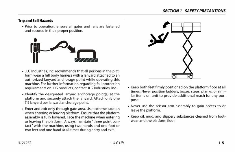
Trip and Fall Hazards• Prior to operation, ensure all gates and rails are fastened
and secured in their proper position.
• JLG Industries, Inc. recommends that all persons in the plat-form wear a full body harness with a lanyard attached to anauthorized lanyard anchorage point while operating thismachine. For further information regarding fall protectionrequirements on JLG products, contact JLG Industries, Inc.
• Identify the designated lanyard anchorage point(s) at theplatform and securely attach the lanyard. Attach only one(1) lanyard per lanyard anchorage point.
• Enter and exit only through gate area. Use extreme cautionwhen entering or leaving platform. Ensure that the platformassembly is fully lowered. Face the machine when enteringor leaving the platform. Always maintain “three point con-tact” with the machine, using two hands and one foot ortwo feet and one hand at all times during entry and exit.
.
• Keep both feet firmly positioned on the platform floor at alltimes. Never position ladders, boxes, steps, planks, or simi-lar items on unit to provide additional reach for any pur-pose.
• Never use the scissor arm assembly to gain access to orleave the platform.
• Keep oil, mud, and slippery substances cleaned from foot-wear and the platform floor.
3121272 – JLG Lift – 1-5
SECTION 1 - SAFETY PRECAUTIONS
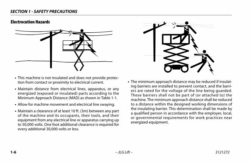
Electrocution Hazards
• This machine is not insulated and does not provide protec-tion from contact or proximity to electrical current.
• Maintain distance from electrical lines, apparatus, or anyenergized (exposed or insulated) parts according to theMinimum Approach Distance (MAD) as shown in Table 1-1.
• Allow for machine movement and electrical line swaying.
• Maintain a clearance of at least 10 ft. (3m) between any partof the machine and its occupants, their tools, and theirequipment from any electrical line or apparatus carrying upto 50,000 volts. One foot additional clearance is required forevery additional 30,000 volts or less.
• The minimum approach distance may be reduced if insulat-ing barriers are installed to prevent contact, and the barri-ers are rated for the voltage of the line being guarded.These barriers shall not be part of (or attached to) themachine. The minimum approach distance shall be reducedto a distance within the designed working dimensions ofthe insulating barrier. This determination shall be made bya qualified person in accordance with the employer, local,or governmental requirements for work practices nearenergized equipment.
1-6 – JLG Lift – 3121272
SECTION 1 - SAFETY PRECAUTIONS
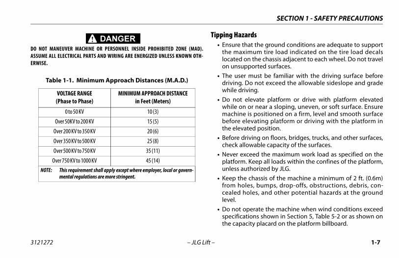
DO NOT MANEUVER MACHINE OR PERSONNEL INSIDE PROHIBITED ZONE (MAD).ASSUME ALL ELECTRICAL PARTS AND WIRING ARE ENERGIZED UNLESS KNOWN OTH-ERWISE.
Tipping Hazards• Ensure that the ground conditions are adequate to support
the maximum tire load indicated on the tire load decalslocated on the chassis adjacent to each wheel. Do not travelon unsupported surfaces.
• The user must be familiar with the driving surface beforedriving. Do not exceed the allowable sideslope and gradewhile driving.
• Do not elevate platform or drive with platform elevatedwhile on or near a sloping, uneven, or soft surface. Ensuremachine is positioned on a firm, level and smooth surfacebefore elevating platform or driving with the platform inthe elevated position.
• Before driving on floors, bridges, trucks, and other surfaces,check allowable capacity of the surfaces.
• Never exceed the maximum work load as specified on theplatform. Keep all loads within the confines of the platform,unless authorized by JLG.
• Keep the chassis of the machine a minimum of 2 ft. (0.6m)from holes, bumps, drop-offs, obstructions, debris, con-cealed holes, and other potential hazards at the groundlevel.
• Do not operate the machine when wind conditions exceedspecifications shown in Section 5, Table 5-2 or as shown onthe capacity placard on the platform billboard.
Table 1-1. Minimum Approach Distances (M.A.D.)
VOLTAGE RANGE(Phase to Phase)
MINIMUM APPROACH DISTANCEin Feet (Meters)
0 to 50 KV 10 (3)
Over 50KV to 200 KV 15 (5)
Over 200 KV to 350 KV 20 (6)
Over 350 KV to 500 KV 25 (8)
Over 500 KV to 750 KV 35 (11)
Over 750 KV to 1000 KV 45 (14)NOTE: This requirement shall apply except where employer, local or govern-
mental regulations are more stringent.
3121272 – JLG Lift – 1-7
SECTION 1 - SAFETY PRECAUTIONS
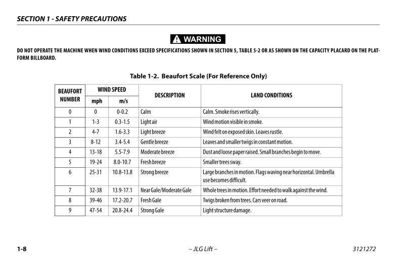
DO NOT OPERATE THE MACHINE WHEN WIND CONDITIONS EXCEED SPECIFICATIONS SHOWN IN SECTION 5, TABLE 5-2 OR AS SHOWN ON THE CAPACITY PLACARD ON THE PLAT-FORM BILLBOARD.
Table 1-2. Beaufort Scale (For Reference Only)
BEAUFORT NUMBER
WIND SPEEDDESCRIPTION LAND CONDITIONS
mph m/s
0 0 0-0.2 Calm Calm. Smoke rises vertically.
1 1-3 0.3-1.5 Light air Wind motion visible in smoke.
2 4-7 1.6-3.3 Light breeze Wind felt on exposed skin. Leaves rustle.
3 8-12 3.4-5.4 Gentle breeze Leaves and smaller twigs in constant motion.
4 13-18 5.5-7.9 Moderate breeze Dust and loose paper raised. Small branches begin to move.
5 19-24 8.0-10.7 Fresh breeze Smaller trees sway.
6 25-31 10.8-13.8 Strong breeze Large branches in motion. Flags waving near horizontal. Umbrella use becomes difficult.
7 32-38 13.9-17.1 Near Gale/Moderate Gale Whole trees in motion. Effort needed to walk against the wind.
8 39-46 17.2-20.7 Fresh Gale Twigs broken from trees. Cars veer on road.
9 47-54 20.8-24.4 Strong Gale Light structure damage.
1-8 – JLG Lift – 3121272
SECTION 1 - SAFETY PRECAUTIONS
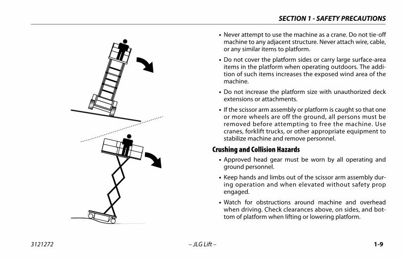
• Never attempt to use the machine as a crane. Do not tie-offmachine to any adjacent structure. Never attach wire, cable,or any similar items to platform.
• Do not cover the platform sides or carry large surface-areaitems in the platform when operating outdoors. The addi-tion of such items increases the exposed wind area of themachine.
• Do not increase the platform size with unauthorized deckextensions or attachments.
• If the scissor arm assembly or platform is caught so that oneor more wheels are off the ground, all persons must beremoved before attempting to free the machine. Usecranes, forklift trucks, or other appropriate equipment tostabilize machine and remove personnel.
Crushing and Collision Hazards• Approved head gear must be worn by all operating and
ground personnel.
• Keep hands and limbs out of the scissor arm assembly dur-ing operation and when elevated without safety propengaged.
• Watch for obstructions around machine and overheadwhen driving. Check clearances above, on sides, and bot-tom of platform when lifting or lowering platform.
3121272 – JLG Lift – 1-9
SECTION 1 - SAFETY PRECAUTIONS
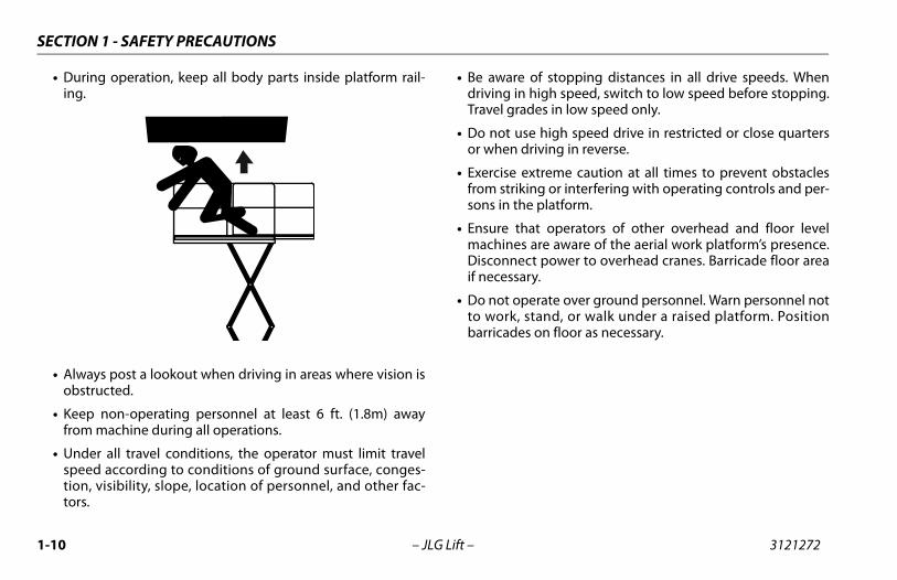
• During operation, keep all body parts inside platform rail-ing.
• Always post a lookout when driving in areas where vision isobstructed.
• Keep non-operating personnel at least 6 ft. (1.8m) awayfrom machine during all operations.
• Under all travel conditions, the operator must limit travelspeed according to conditions of ground surface, conges-tion, visibility, slope, location of personnel, and other fac-tors.
• Be aware of stopping distances in all drive speeds. Whendriving in high speed, switch to low speed before stopping.Travel grades in low speed only.
• Do not use high speed drive in restricted or close quartersor when driving in reverse.
• Exercise extreme caution at all times to prevent obstaclesfrom striking or interfering with operating controls and per-sons in the platform.
• Ensure that operators of other overhead and floor levelmachines are aware of the aerial work platform’s presence.Disconnect power to overhead cranes. Barricade floor areaif necessary.
• Do not operate over ground personnel. Warn personnel notto work, stand, or walk under a raised platform. Positionbarricades on floor as necessary.
1-10 – JLG Lift – 3121272
SECTION 1 - SAFETY PRECAUTIONS
1.4 TOWING, LIFTING, AND HAULING• Never allow personnel in platform while towing, lifting, or
hauling.
• This machine should not be towed, except in the event ofemergency, malfunction, power failure, or loading/unload-ing. Refer to emergency towing procedures.
• Ensure platform is fully retracted and completely empty oftools prior to towing, lifting or hauling.
• When lifting machine with a forklift, position forks only atdesignated areas of the machine. Lift with a forklift of ade-quate capacity.
• Refer to Section 3 for lifting information.
1.5 MAINTENANCE
This sub-section contains general safety precautions whichmust be observed during maintenance of this machine. Addi-tional precautions to be observed during machine mainte-nance are inserted at the appropriate points in this manualand in the Service and Maintenance Manual. It is of utmostimportance that maintenance personnel pay strict attentionto these precautions to avoid possible injury to personnel ordamage to the machine or property. A maintenance program
must be established by a qualified person and must be fol-lowed to ensure that the machine is safe.
Maintenance Hazards• Shut off power to all controls and ensure that all moving
parts are secured from inadvertent motion prior to per-forming any adjustments or repairs.
• Never work under an elevated platform until it has beenfully lowered to the full down position, if possible, or other-wise supported and restrained from movement with appro-priate safety props, blocking, or overhead supports.
• DO NOT attempt to repair or tighten any hydraulic hoses orfittings while the machine is powered on or when thehydraulic system is under pressure.
• Always relieve hydraulic pressurefrom all hydraulic circuits beforeloosening or removing hydrauliccomponents.
• DO NOT use your hand to check forleaks. Use a piece of cardboard orpaper to search for leaks. Weargloves to help protect hands fromspraying fluid.
• Ensure replacement parts or components are identical orequivalent to original parts or components.
3121272 – JLG Lift – 1-11
SECTION 1 - SAFETY PRECAUTIONS
• Never attempt to move heavy parts without the aid of amechanical device. Do not allow heavy objects to rest in anunstable position. Ensure adequate support is providedwhen raising components of the machine.
• Use only approved non-flammable cleaning solvents.
• Do not replace items critical to stability, such as batteries orsolid tires, with items of different weight or specification.Do not modify unit in any way to affect stability.
• Reference the Service and Maintenance Manual for theweights of critical stability items.
MODIFICATION OR ALTERATION OF AN AERIAL WORK PLATFORM SHALL BEMADE ONLY WITH PRIOR WRITTEN PERMISSION FROM THE MANUFACTURER.
Battery Hazards• Always disconnect batteries when servicing electrical com-
ponents or when performing welding on the machine.
• Do not allow smoking, open flame, or sparks near batteryduring charging or servicing.
• Do not contact tools or other metal objects across the bat-tery terminals.
• Always wear hand, eye, and face protection when servicingbatteries. Ensure that battery acid does not come in contactwith skin or clothing.
BATTERY FLUID IS HIGHLY CORROSIVE. AVOID CONTACT WITH SKIN ANDCLOTHING AT ALL TIMES. IMMEDIATELY RINSE ANY CONTACTED AREA WITHCLEAN WATER AND SEEK MEDICAL ATTENTION.
• Charge batteries only in a well ventilated area.
• Avoid overfilling the battery fluid level. Add distilled waterto batteries only after the batteries are fully charged.
1-12 – JLG Lift – 3121272
SECTION 2 - USER RESPONSIBILITIES, MACHINE PREPARATION AND INSPECTION
SECTION 2. USER RESPONSIBILITIES, MACHINE PREPARATION AND INSPECTION
2.1 PERSONNEL TRAININGThe aerial platform is a personnel handling device; so it is neces-sary that it be operated and maintained only by trained person-nel.
Operator TrainingOperator training must cover:
• Use and limitations of the controls in the platform and at theground, emergency controls and safety features.
• Control labels, instructions, and warnings on the machine.
• Rules of the employer and government regulations.
• Use of approved fall protection equipment.
• Enough knowledge of the mechanical operation of the machine torecognize a malfunction or potential malfunction.
• The safest means to operate the machine where overhead obstruc-tions, other moving equipment, and obstacles, depressions, holes,and drop-offs exist.
• Means to avoid the hazards of unprotected electrical conductors.
• Specific job requirements or machine application.
• Reading and understanding the Operation and Safety Manual.
3121272 – JLG Lift – 2-1
SECTION 2 - USER RESPONSIBILITIES, MACHINE PREPARATION AND INSPECTION
Training SupervisionTraining must be done under the supervision of a qualified per-son in an open area free of obstructions until the trainee hasdeveloped the ability to safely control and operate the machine.
Operator ResponsibilityThe operator must be instructed that he/she has the responsi-bility and authority to shut down the machine in case of a mal-function or other unsafe condition of either the machine or thejob site.
NOTE: The Manufacturer or Distributor will provide qualifiedpeople for training assistance with the first unit(s) deliv-ered and from that time forward as requested by the useror his/her personnel.
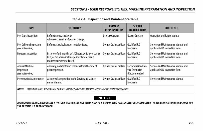
2.2 PREPARATION, INSPECTION, AND MAINTENANCETable 2-1 explains the periodic machine inspections and main-tenance recommended by JLG Industries, Inc. Consult local reg-ulations for further requirements for aerial work platforms. Thefrequency of inspections and maintenance must be increasedas necessary when the machine is used in a harsh or hostileenvironment, if the machine is used with increased frequency,or if the machine is used in a severe manner.
2-2 – JLG Lift – 3121272
SECTION 2 - USER RESPONSIBILITIES, MACHINE PREPARATION AND INSPECTION
Table 2-1. Inspection and Maintenance Table
TYPE FREQUENCY PRIMARYRESPONSIBILITY
SERVICE QUALIFICATION REFERENCE
Pre-Start Inspection Before using each day; or whenever there’s an Operator change.
User or Operator User or Operator Operation and Safety Manual
Pre-Delivery Inspection(see note below)
Before each sale, lease, or rental delivery. Owner, Dealer, or User Qualified JLG Mechanic
Service and Maintenance Manual and applicable JLG inspection form
Frequent Inspection In service for 3 months or 150 hours, whichever comes first; or Out of service for a period of more than 3 months; or Purchased used.
Owner, Dealer, or User Qualified JLG Mechanic
Service and Maintenance Manual and applicable JLG inspection form
Annual MachineInspection(see note below)
Annually, no later than 13 months from the date of prior inspection.
Owner, Dealer, or User Factory Trained Ser-vice Technician (Recommended)
Service and Maintenance Manual and applicable JLG inspection form
Preventative Maintenance At intervals as specified in the Service and Mainte-nance Manual.
Owner, Dealer, or User Qualified JLG Mechanic
Service and Maintenance Manual
NOTE: Inspection forms are available from JLG. Use the Service and Maintenance Manual to perform inspections.
JLG INDUSTRIES, INC. RECOGNIZES A FACTORY-TRAINED SERVICE TECHNICIAN AS A PERSON WHO HAS SUCCESSFULLY COMPLETED THE JLG SERVICE TRAINING SCHOOL FORTHE SPECIFIC JLG PRODUCT MODEL.
NOTICE
3121272 – JLG Lift – 2-3
SECTION 2 - USER RESPONSIBILITIES, MACHINE PREPARATION AND INSPECTION
2.3 PRE-START INSPECTIONThe Pre-Start Inspection should include each of the following:
1. Cleanliness – Check all surfaces for leakage (oil or bat-tery fluid) or foreign objects. Report this to the proper maintenance personnel.
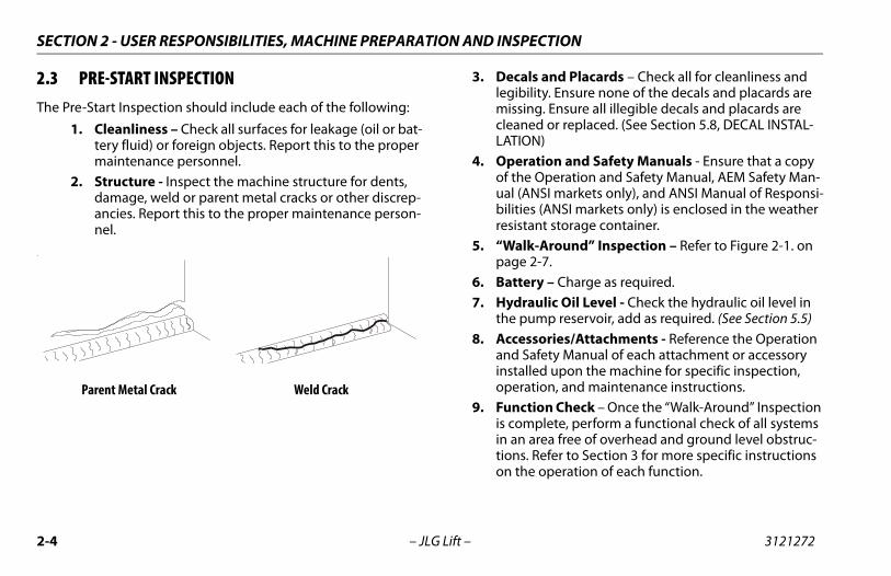
2. Structure - Inspect the machine structure for dents, damage, weld or parent metal cracks or other discrep-ancies. Report this to the proper maintenance person-nel.
3. Decals and Placards – Check all for cleanliness and legibility. Ensure none of the decals and placards are missing. Ensure all illegible decals and placards are cleaned or replaced. (See Section 5.8, DECAL INSTAL-LATION)
4. Operation and Safety Manuals - Ensure that a copy of the Operation and Safety Manual, AEM Safety Man-ual (ANSI markets only), and ANSI Manual of Responsi-bilities (ANSI markets only) is enclosed in the weather resistant storage container.
5. “Walk-Around” Inspection – Refer to Figure 2-1. on page 2-7.
6. Battery – Charge as required.7. Hydraulic Oil Level - Check the hydraulic oil level in
the pump reservoir, add as required. (See Section 5.5)8. Accessories/Attachments - Reference the Operation
and Safety Manual of each attachment or accessory installed upon the machine for specific inspection, operation, and maintenance instructions.
9. Function Check – Once the “Walk-Around” Inspection is complete, perform a functional check of all systems in an area free of overhead and ground level obstruc-tions. Refer to Section 3 for more specific instructions on the operation of each function.
.
Parent Metal Crack Weld Crack
2-4 – JLG Lift – 3121272
SECTION 2 - USER RESPONSIBILITIES, MACHINE PREPARATION AND INSPECTION
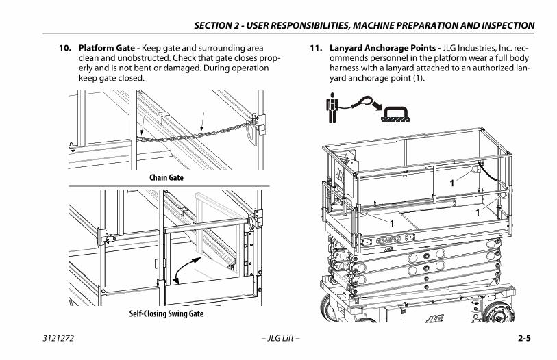
10. Platform Gate - Keep gate and surrounding area clean and unobstructed. Check that gate closes prop-erly and is not bent or damaged. During operation keep gate closed.
11. Lanyard Anchorage Points - JLG Industries, Inc. rec-ommends personnel in the platform wear a full body harness with a lanyard attached to an authorized lan-yard anchorage point (1).
Chain Gate
Self-Closing Swing Gate
1
1
1
3121272 – JLG Lift – 2-5
SECTION 2 - USER RESPONSIBILITIES, MACHINE PREPARATION AND INSPECTION
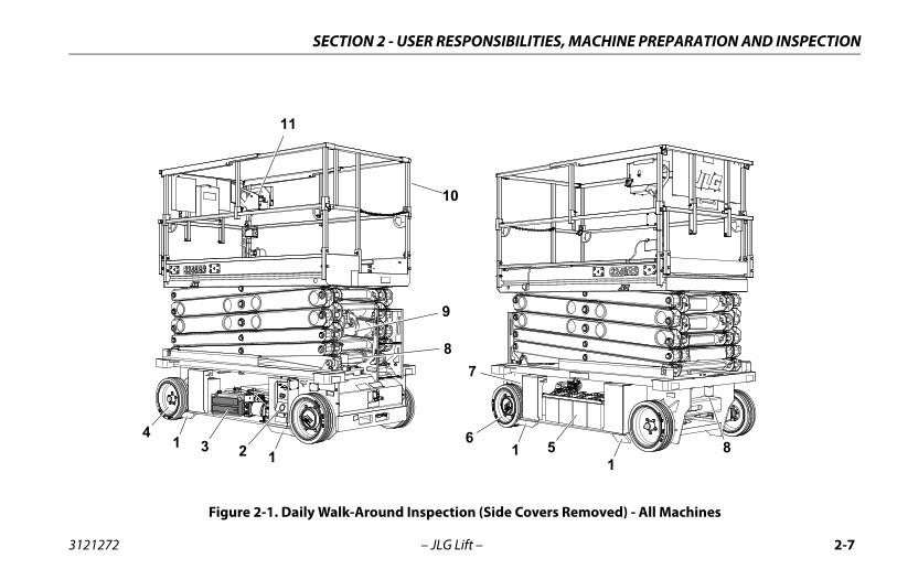
2.4 DAILY WALK-AROUND INSPECTIONBegin the “Walk-Around Inspection” at item 1, see Figure 2-1. onpage 2-7. Continue checking each item in sequence for the con-ditions listed in the following checklist.
TO AVOID POSSIBLE INJURY, BE SURE MACHINE POWER IS “OFF”. DO NOTOPERATE UNTIL ALL MALFUNCTIONS HAVE BEEN CORRECTED.
NOTICEDO NOT OVERLOOK VISUAL INSPECTION OF CHASSIS UNDERSIDE. CHECKINGTHIS AREA MAY RESULT IN DISCOVERY OF CONDITIONS WHICH COULD CAUSEEXTENSIVE MACHINE DAMAGE.INSPECTION NOTE: On all components, make sure there are noloose or missing parts, that they are securely fastened, and thatno visible damage, leaks or excessive wear exists in addition toany other criteria mentioned.
1. Frame/Chassis - See Inspection Note. Ensure that pas-sive pothole components on frame are in place, undamaged, not bent or worn.
2. Ground Controls - Placard secure and legible, control switches return to neutral position, emergency stop switch functions properly. Control markings legible.
3. Hydraulic Pump/Motor, Control Valve Installation - No unsupported wires or hoses; no damaged or broken wires - See Inspection Note.
4. Front Wheels - Steer linkage, and Steer Cylinder - See Inspection Note.
5. Battery Compartment - See Inspection Note.6. Rear Wheels, Tires and Drive Motors - Properly
secured, no missing lug nuts. Refer to Section 5.7, TIRES AND WHEELS. Inspect wheels for damage and corrosion - See Inspection Note.
7. Manual Descent Control - See Inspection Note.8. Beacon (if equipped) - See Inspection Note.9. Scissor Arms, Pivot Pins and Sliding Wear Pads, Lift Cyl-
inder - See Inspection Note.10. Platform/Handrail/Gate Installation - Deck extension
slides in and out and locks in place properly. Gate closes properly. All fold-down rail pins in place and secure (3248RS/10RS and 6RS CE ONLY) - See Inspec-tion Note.
11. Platform Control Console - Ensure that the control console is firmly secured in the proper location. Plac-ards secure and legible, control lever and switches return to neutral, and emergency stop switch function properly, required manuals in storage box.
2-6 – JLG Lift – 3121272
SECTION 2 - USER RESPONSIBILITIES, MACHINE PREPARATION AND INSPECTION
Figure 2-1. Daily Walk-Around Inspection (Side Covers Removed) - All Machines
1 23 5
7
6
8
9
10
11
481 1
1
3121272 – JLG Lift – 2-7
SECTION 2 - USER RESPONSIBILITIES, MACHINE PREPARATION AND INSPECTION
2.5 FUNCTION CHECKPerform the Function Check as follows:
1. From the Ground Control Panel with no load in the platform:a. Ensure that the key selector switch and the plat-
form lift switch operates properly.b. Ensure that all machine functions are disabled
when the Emergency Stop Button is depressed.c. With platform raised a few feet (1m), ensure that
the manual descent control (located at the rightrear of the machine), lowers the platform properly.
2. From the Platform Control Console:a. Ensure that the control console is firmly secured
in the proper location.b. Ensure that all guards protecting switches are in
place.c. Operate all functions, drive/lift mode select
switch, and horn button.d. Operate all platform joystick functions to ensure
proper operation of drive, lift, steer, and enabletrigger switch operation.
e. With the platform elevated on a smooth, firm,level surface with no overhead obstructions, drivethe machine to check if the high drive cutout
speed-limit is engaged at the height indicated inTable 2-2. Ensure drive speed is reduced from atop speed to a slower speed. Limit switch loca-tions shown in Figure 2-2. on page 2-9.
f. Ensure that all machine functions are disabledwhen the platform Emergency Stop Button isdepressed.
3. With the platform in the transport (stowed) position.a. Drive the machine on a grade, not to exceed the
rated gradeability, and stop to ensure the drivemotor brakes hold.
b. Check the tilt indicator light/alarm to ensureproper operation. The light/alarm should be acti-vated, and lift up disabled when tilted at orbeyond the values in Table 2-3.
NOTE: When the tilt indicator warning is activated the followingfunctions are affected; drive and lift up functions are dis-
Table 2-2. High Drive Cutout Height
MODEL HIGH DRIVE SPEED CUTOUT HEIGHT DRIVE SPEED REDUCTION
1932RS/6RS 68.9 in. (1.75m) 2.5 mph (4 kph) to0.3 mph (0.5 kph)3248RS/10RS 88.5 in. (2.25 m)
2-8 – JLG Lift – 3121272
SECTION 2 - USER RESPONSIBILITIES, MACHINE PREPARATION AND INSPECTION
abled, platform must be fully lowered (stowed) to driveout of tilt condition.
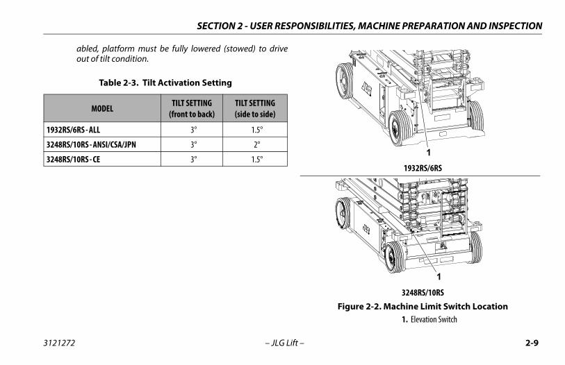
Table 2-3. Tilt Activation Setting
MODEL TILT SETTING(front to back)
TILT SETTING(side to side)
1932RS/6RS - ALL 3° 1.5°
3248RS/10RS - ANSI/CSA/JPN 3° 2°
3248RS/10RS - CE 3° 1.5° 1932RS/6RS
3248RS/10RSFigure 2-2. Machine Limit Switch Location
1. Elevation Switch
1
1
3121272 – JLG Lift – 2-9
SECTION 2 - USER RESPONSIBILITIES, MACHINE PREPARATION AND INSPECTION
NOTES:
2-10 – JLG Lift – 3121272
SECTION 3 - MACHINE CONTROLS, INDICATORS AND OPERATION
SECTION 3. MACHINE CONTROLS, INDICATORS AND OPERATION
3.1 GENERAL
NOTICETHE MANUFACTURER HAS NO DIRECT CONTROL OVER MACHINE APPLICA-TION AND OPERATION, THE USER AND OPERATOR ARE RESPONSIBLE FORCONFORMING WITH GOOD SAFETY PRACTICES.This section provides the necessary information needed tounderstand controls and their functions.
DO NOT RAISE PLATFORM EXCEPT ON A SMOOTH, FIRM AND LEVEL SURFACEFREE OF OBSTRUCTIONS AND HOLES.
TO AVOID SERIOUS INJURY, DO NOT OPERATE MACHINE IF ANY CONTROLLEVERS OR TOGGLE SWITCHES CONTROLLING PLATFORM MOVEMENT DO NOTRETURN TO THE OFF OR NEUTRAL POSITION WHEN RELEASED.
IF THE PLATFORM DOES NOT STOP WHEN A CONTROL SWITCH OR LEVER ISRELEASED, USE THE EMERGENCY STOP SWITCH TO STOP THE MACHINE.
3.2 DESCRIPTIONThis machine is a self-propelled aerial work platform on top ofan elevating scissor arm mechanism. The Lift’s intended pur-pose is to position personnel with their tools and supplies atpositions above ground level. The machine can be used to reachwork areas located above machinery or equipment positionedat ground level.
This JLG Lift has a primary operator control station in the plat-form. From this control station, the operator can drive and steerthe machine in both forward and reverse directions, raise andlower the platform.The machine can be driven on a smooth, firm, and level surfacefrom an elevated platform position - Reference “Steering AndTraveling” on page 3-12. of this manual for specific require-ments.
The machine also has a ground control station which can over-ride the platform control station. Ground controls operate lift upand down. Ground controls are to be used only in an emergencyto lower the platform to the ground should the operator in theplatform be unable to do so.
3121272 – JLG Lift – 3-1
SECTION 3 - MACHINE CONTROLS, INDICATORS AND OPERATION
3.3 OPERATING CHARACTERISTICS AND LIMITATIONS
GeneralA thorough knowledge of the operating characteristics and lim-itations of the machine is always the first requirement for anyuser, regardless of user’s experience with similar types of equip-ment.
PlacardsImportant points to remember during operation are provided atthe control stations by DANGER, WARNING, CAUTION, NOTICE,and INSTRUCTION placards. This information is placed at variouslocations for the express purpose of alerting personnel ofpotential hazards constituted by the operating characteristicsand limitations of the machine. See foreword for definitions ofplacard safety signal words.
3.4 PLATFORM LOADINGThe platform maximum rated load capacity is shown on a plac-ard located on the platform billboard and ground control sta-tion and is based upon the machine positioned on a smooth,firm, and level surface. Refer to Section 5, Table 5-2 on page 5-4,for the maximum platform capacity.
The platform is entered through an entry gate at the rear of theplatform. Keep entry gate closed during machine operation.
NOTE: It is important to remember that the load should beevenly distributed on the platform. The load should beplaced near the center of the platform when possible.
3-2 – JLG Lift – 3121272
SECTION 3 - MACHINE CONTROLS, INDICATORS AND OPERATION
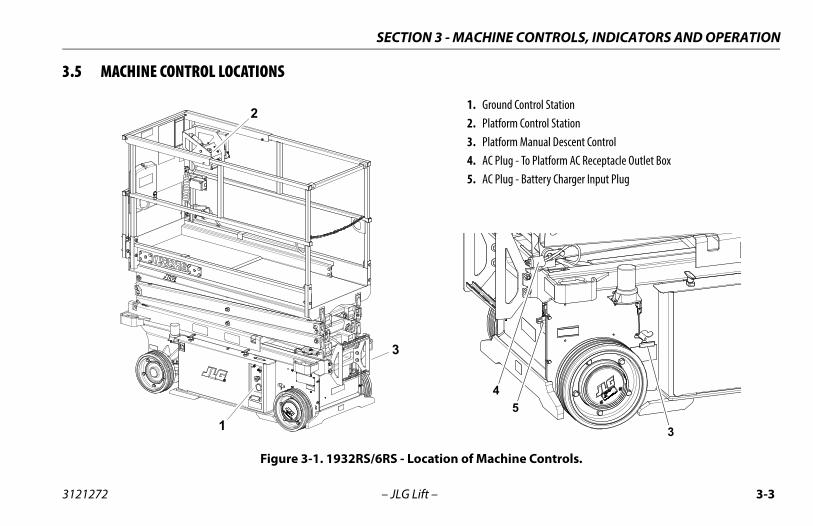
3.5 MACHINE CONTROL LOCATIONS
1. Ground Control Station2. Platform Control Station3. Platform Manual Descent Control4. AC Plug - To Platform AC Receptacle Outlet Box5. AC Plug - Battery Charger Input Plug
Figure 3-1. 1932RS/6RS - Location of Machine Controls.
1
2
3
3
45
3121272 – JLG Lift – 3-3
SECTION 3 - MACHINE CONTROLS, INDICATORS AND OPERATION
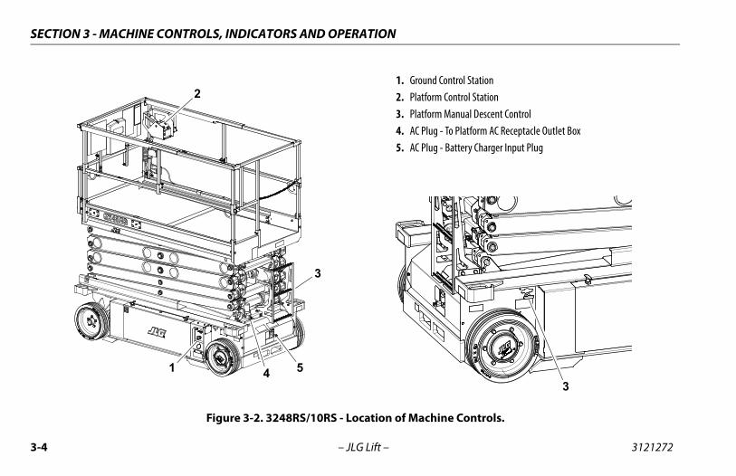
1. Ground Control Station2. Platform Control Station3. Platform Manual Descent Control4. AC Plug - To Platform AC Receptacle Outlet Box5. AC Plug - Battery Charger Input Plug
Figure 3-2. 3248RS/10RS - Location of Machine Controls.
1 4 5
2
3
3
3-4 – JLG Lift – 3121272
SECTION 3 - MACHINE CONTROLS, INDICATORS AND OPERATION
3.6 GROUND CONTROL STATION
DO NOT OPERATE FROM GROUND CONTROL STATION WITH PERSONNEL INTHE PLATFORM EXCEPT IN AN EMERGENCY.
PERFORM AS MANY PRE-OPERATIONAL CHECKS AND INSPECTIONS FROMTHE GROUND CONTROL STATION AS POSSIBLE.
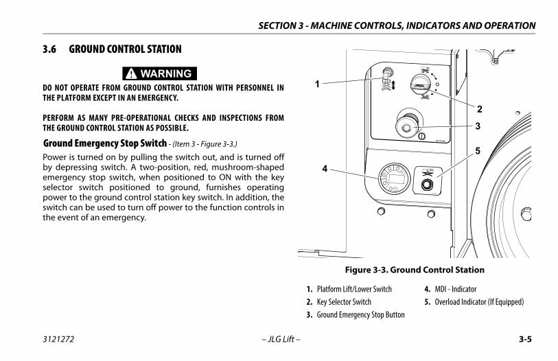
Ground Emergency Stop Switch - (Item 3 - Figure 3-3.)
Power is turned on by pulling the switch out, and is turned offby depressing switch. A two-position, red, mushroom-shapedemergency stop switch, when positioned to ON with the keyselector switch positioned to ground, furnishes operatingpower to the ground control station key switch. In addition, theswitch can be used to turn off power to the function controls inthe event of an emergency.
Figure 3-3. Ground Control Station
1. Platform Lift/Lower Switch2. Key Selector Switch3. Ground Emergency Stop Button
4. MDI - Indicator5. Overload Indicator (If Equipped)
1001132360A
1
2
3
4
5
1001146979A
3121272 – JLG Lift – 3-5
SECTION 3 - MACHINE CONTROLS, INDICATORS AND OPERATION
Key Selector Switch - (Item 2 - Figure 3-3.)
The key selector switch on theGround Control Station functions todirect electrical power to the desiredcontrol station. With the switchturned to the ground position (1),power is supplied to the controls atthe ground control station. When theswitch is turned to the platformposition (2), power is supplied to thecontrols at the platform control sta-tion. The switch should be set to the OFF position (3) whenparking the machine overnight.
Platform Lift/Lower Switch - (Item 1 - Figure 3-3.)
A three position, momentary contact lift control switch providesraising and lowering of the platform from the Ground ControlStation.
When operating platform from the ground controls -Toggle the lift/lower switch to up position and hold to raise plat-form, or down position and hold to lower an elevated platform.Release to center position to stop all movement.
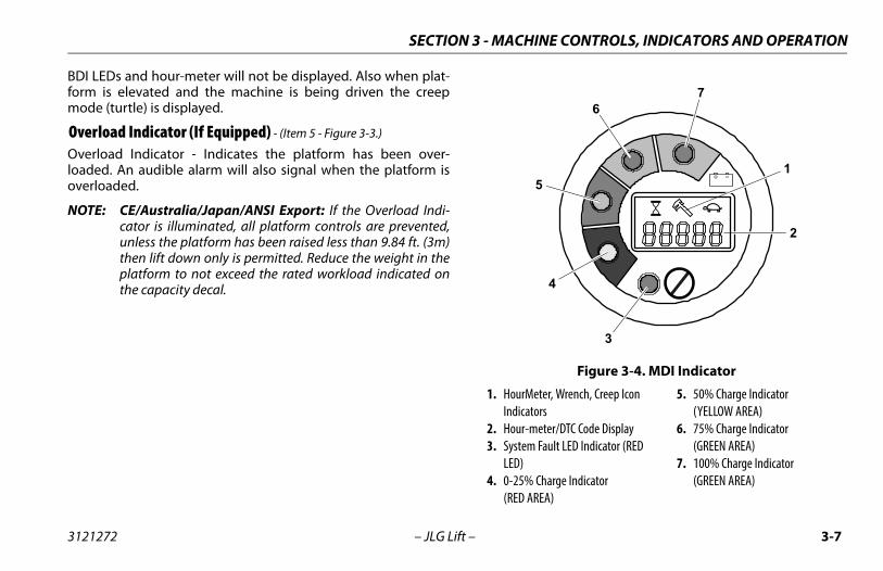
MDI-Indicator - (Item 4 - Figure 3-3.)
The MDI indicator or Multifunction Digital Indicator displays aBattery Discharge Indicator (BDI), an LCD display which showsthe current hour-meter reading or Diagnostic Trouble Code(s)
(DTC) when a functional problem occurs with the machine, anda system distress LED.
When a problem occurs (DTC Code displayed):
A wrench Icon (item 1) will display on the Diagnostic TroubleCode LCD display (item 2). (See Figure 3-4.)
• A three to five digit DTC code will display on the DiagnosticTrouble Code LCD display (item 2), below the wrenchicon.
• The system distress LED indicator (RED) (item 3) lights upsolid on the MDI when a DTC Code is displayed on the LCDdisplay.
NOTE: When more than one DTC exists, each DTC will be dis-played on the LCD for 3 seconds before changing to thenext DTC. Once the last active DTC is displayed, the displaywill recycle indefinitely until the DTC’s are corrected.For DTC’s and descriptions, refer to Section 5.9.
Also located on the MDI are Battery Discharge Indicators(BDI) (items 4 thru 7). (4) GREEN LEDs indicate the level ofcharge (voltage) remaining in the batteries.
NOTE: When the battery voltage is low and will need a chargesoon, the LED (item 4) in the 0-25% range "red area" willflash.
Under normal operating conditions the BDI’s and hour-meterwill be displayed. When a DTC exists (other than 00x DTC’s) the
1
2
3
3-6 – JLG Lift – 3121272
SECTION 3 - MACHINE CONTROLS, INDICATORS AND OPERATION
BDI LEDs and hour-meter will not be displayed. Also when plat-form is elevated and the machine is being driven the creepmode (turtle) is displayed.
Overload Indicator (If Equipped) - (Item 5 - Figure 3-3.)
Overload Indicator - Indicates the platform has been over-loaded. An audible alarm will also signal when the platform isoverloaded.
NOTE: CE/Australia/Japan/ANSI Export: If the Overload Indi-cator is illuminated, all platform controls are prevented,unless the platform has been raised less than 9.84 ft. (3m)then lift down only is permitted. Reduce the weight in theplatform to not exceed the rated workload indicated onthe capacity decal.
Figure 3-4. MDI Indicator
1. HourMeter, Wrench, Creep Icon Indicators
2. Hour-meter/DTC Code Display3. System Fault LED Indicator (RED
LED)4. 0-25% Charge Indicator
(RED AREA)
5. 50% Charge Indicator(YELLOW AREA)
6. 75% Charge Indicator(GREEN AREA)
7. 100% Charge Indicator(GREEN AREA)
1
2
3
76
5
4
3121272 – JLG Lift – 3-7
SECTION 3 - MACHINE CONTROLS, INDICATORS AND OPERATION
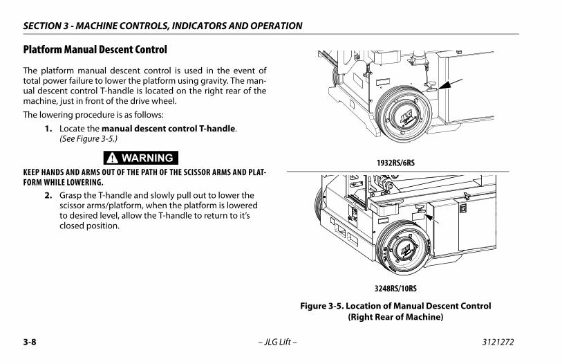
Platform Manual Descent Control
The platform manual descent control is used in the event oftotal power failure to lower the platform using gravity. The man-ual descent control T-handle is located on the right rear of themachine, just in front of the drive wheel.
The lowering procedure is as follows:
1. Locate the manual descent control T-handle.(See Figure 3-5.)
KEEP HANDS AND ARMS OUT OF THE PATH OF THE SCISSOR ARMS AND PLAT-FORM WHILE LOWERING.
2. Grasp the T-handle and slowly pull out to lower the scissor arms/platform, when the platform is lowered to desired level, allow the T-handle to return to it’s closed position.
1932RS/6RS
3248RS/10RS
Figure 3-5. Location of Manual Descent Control(Right Rear of Machine)
3-8 – JLG Lift – 3121272
SECTION 3 - MACHINE CONTROLS, INDICATORS AND OPERATION
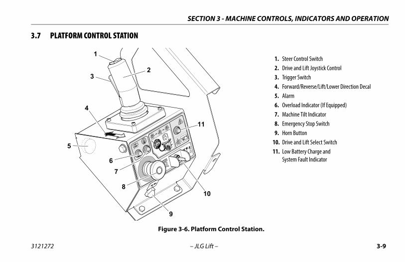
3.7 PLATFORM CONTROL STATION
1. Steer Control Switch2. Drive and Lift Joystick Control3. Trigger Switch4. Forward/Reverse/Lift/Lower Direction Decal5. Alarm6. Overload Indicator (If Equipped)7. Machine Tilt Indicator8. Emergency Stop Switch9. Horn Button
10. Drive and Lift Select Switch11. Low Battery Charge and
System Fault Indicator
Figure 3-6. Platform Control Station.
1001132362 B
1
3
4
8
9
10
2
51
2
67
11
3121272 – JLG Lift – 3-9
SECTION 3 - MACHINE CONTROLS, INDICATORS AND OPERATION
Platform Emergency Stop Switch - (Item 8 - Figure 3-6.)
NOTE: Both the ground and platform emergency stop buttonsmust be set to ON in order to operate the machine.
When power is directed to the platform from the ground controlstation, the platform emergency stop switch is turned on bypulling the switch out (on), and is turned off by pushing theswitch in (off ). The two-position, red, mushroom-shaped emer-gency stop switch functions to provide power to the platformcontrol station and also to turn off power to machine functionsin the event of an emergency.
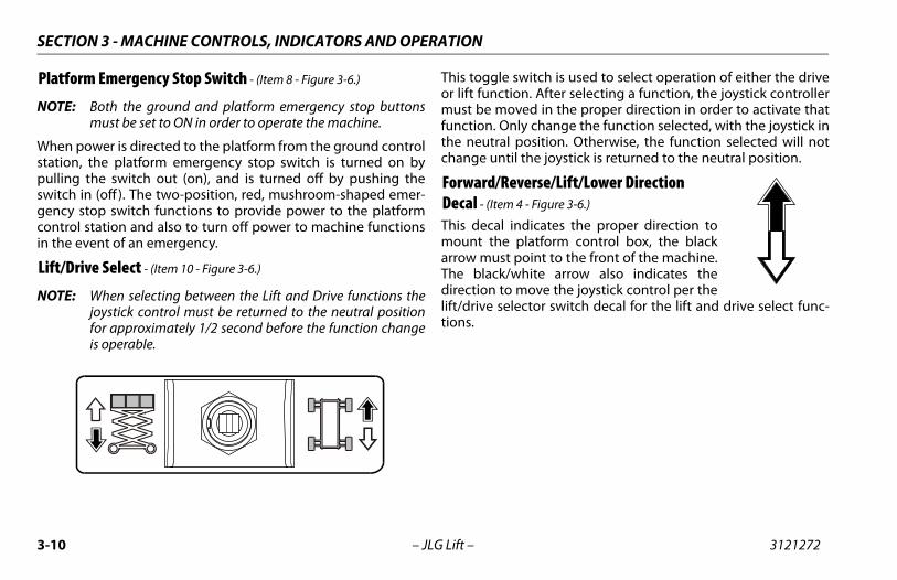
Lift/Drive Select - (Item 10 - Figure 3-6.)
NOTE: When selecting between the Lift and Drive functions thejoystick control must be returned to the neutral positionfor approximately 1/2 second before the function changeis operable.
This toggle switch is used to select operation of either the driveor lift function. After selecting a function, the joystick controllermust be moved in the proper direction in order to activate thatfunction. Only change the function selected, with the joystick inthe neutral position. Otherwise, the function selected will notchange until the joystick is returned to the neutral position.
Forward/Reverse/Lift/Lower Direction Decal - (Item 4 - Figure 3-6.)
This decal indicates the proper direction tomount the platform control box, the blackarrow must point to the front of the machine.The black/white arrow also indicates thedirection to move the joystick control per thelift/drive selector switch decal for the lift and drive select func-tions.
1001132362 B
3-10 – JLG Lift – 3121272
SECTION 3 - MACHINE CONTROLS, INDICATORS AND OPERATION
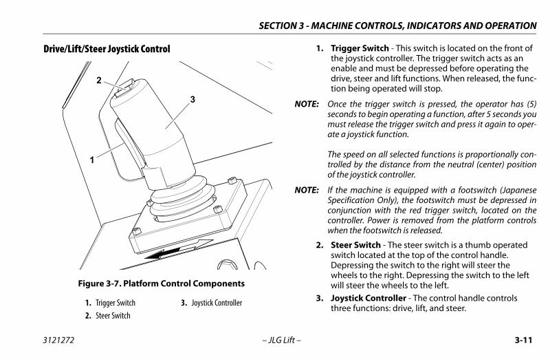
Drive/Lift/Steer Joystick Control 1. Trigger Switch - This switch is located on the front of the joystick controller. The trigger switch acts as an enable and must be depressed before operating the drive, steer and lift functions. When released, the func-tion being operated will stop.
NOTE: Once the trigger switch is pressed, the operator has (5)seconds to begin operating a function, after 5 seconds youmust release the trigger switch and press it again to oper-ate a joystick function.
The speed on all selected functions is proportionally con-trolled by the distance from the neutral (center) positionof the joystick controller.
NOTE: If the machine is equipped with a footswitch (JapaneseSpecification Only), the footswitch must be depressed inconjunction with the red trigger switch, located on thecontroller. Power is removed from the platform controlswhen the footswitch is released.
2. Steer Switch - The steer switch is a thumb operated switch located at the top of the control handle. Depressing the switch to the right will steer the wheels to the right. Depressing the switch to the left will steer the wheels to the left.
3. Joystick Controller - The control handle controls three functions: drive, lift, and steer.
Figure 3-7. Platform Control Components
1. Trigger Switch2. Steer Switch
3. Joystick Controller
2
3
1
3121272 – JLG Lift – 3-11
SECTION 3 - MACHINE CONTROLS, INDICATORS AND OPERATION
Steering And Traveling
DO NOT DRIVE WITH PLATFORM RAISED EXCEPT ON A SMOOTH, FIRM ANDLEVEL SURFACE FREE OF OBSTRUCTIONS AND HOLES.
TO AVOID LOSS OF TRAVEL CONTROL OR UPSET ON GRADES AND SIDESLOPES,DO NOT DRIVE MACHINE ON GRADES OR SIDESLOPES EXCEEDING THOSESPECIFIED IN TABLE 5-1 ON PAGE 5-2.
BEFORE DRIVING, LOCATE THE DECALS WITH THE BLACK/WHITE ORIENTA-TION ARROWS ON THE CHASSIS AND THE PLATFORM CONTROLS. MOVE THEJOYSTICK IN THE DIRECTION OF THE BLACK OR WHITE ARROW THATMATCHES THE COLOR OF THE ARROW ON THE CHASSIS FOR THE INTENDEDDIRECTION OF TRAVEL.
IF THE TILT INDICATOR WARNING LIGHT/ALARM IS ACTIVATED WHILE DRIV-ING WITH PLATFORM RAISED, LOWER PLATFORM COMPLETELY AND DRIVETO A FIRM LEVEL SURFACE.
1. Place key selector switch at the ground control station to platform operation.
2. Position emergency stop switches, one at the platform and one at the ground control station to the ON posi-tion.
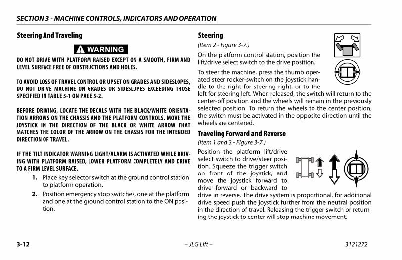
Steering(Item 2 - Figure 3-7.)
On the platform control station, position thelift/drive select switch to the drive position.
To steer the machine, press the thumb oper-ated steer rocker-switch on the joystick han-dle to the right for steering right, or to theleft for steering left. When released, the switch will return to thecenter-off position and the wheels will remain in the previouslyselected position. To return the wheels to the center position,the switch must be activated in the opposite direction until thewheels are centered.
Traveling Forward and Reverse(Item 1 and 3 - Figure 3-7.)
Position the platform lift/driveselect switch to drive/steer posi-tion. Squeeze the trigger switchon front of the joystick, andmove the joystick forward todrive forward or backward todrive in reverse. The drive system is proportional, for additionaldrive speed push the joystick further from the neutral positionin the direction of travel. Releasing the trigger switch or return-ing the joystick to center will stop machine movement.
3-12 – JLG Lift – 3121272
SECTION 3 - MACHINE CONTROLS, INDICATORS AND OPERATION
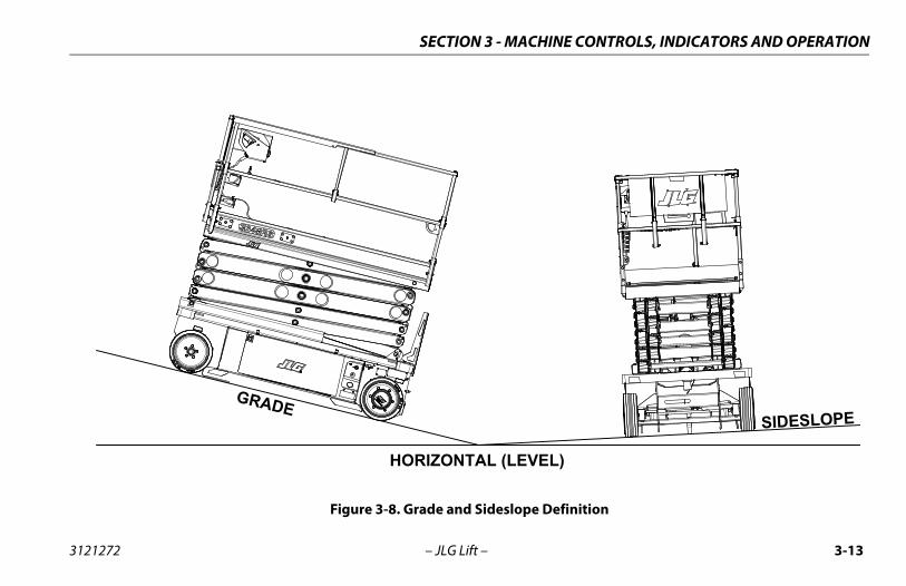
Figure 3-8. Grade and Sideslope Definition
HORIZONTAL (LEVEL)
GRADESIDESLOPE
3121272 – JLG Lift – 3-13
SECTION 3 - MACHINE CONTROLS, INDICATORS AND OPERATION
Raising And Lowering Platform1. If the machine was shut down, place the key selector
switch to the desired position (platform or ground).2. Position emergency stop switches, one at the platform
and one at the ground control station to the ON posi-tion.
3. Position the lift/drive select switch to lift. (Item 10 - Figure 3-6.)
4. Squeeze and hold the trigger switch, and move the joystick back (platform up - white arrow direction) or move the joy-stick forward (platform down - black arrow direction) and hold until desired elevation is reached. Releasing the trigger switch or moving the joystick back to it’s center position will stop the function being operated. (Item 1 and 3 - Figure 3-7.)
NOTE: To ensure proper operation of the desired platform func-tion, move the joystick in the direction of the black orwhite arrow that matches the color of the arrow on thechassis for the intended direction of travel.
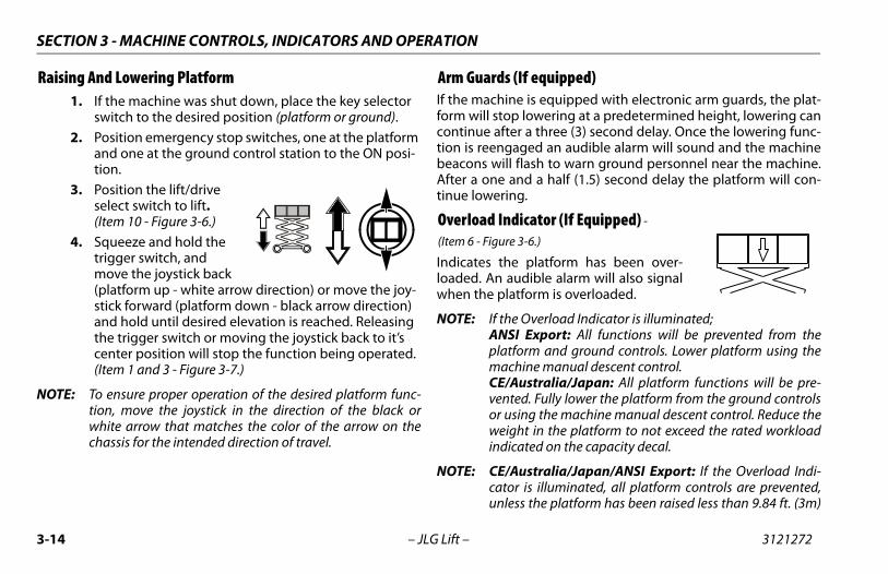
Arm Guards (If equipped)If the machine is equipped with electronic arm guards, the plat-form will stop lowering at a predetermined height, lowering cancontinue after a three (3) second delay. Once the lowering func-tion is reengaged an audible alarm will sound and the machinebeacons will flash to warn ground personnel near the machine.After a one and a half (1.5) second delay the platform will con-tinue lowering.
Overload Indicator (If Equipped) -
(Item 6 - Figure 3-6.)
Indicates the platform has been over-loaded. An audible alarm will also signalwhen the platform is overloaded.
NOTE: If the Overload Indicator is illuminated;ANSI Export: All functions will be prevented from theplatform and ground controls. Lower platform using themachine manual descent control.CE/Australia/Japan: All platform functions will be pre-vented. Fully lower the platform from the ground controlsor using the machine manual descent control. Reduce theweight in the platform to not exceed the rated workloadindicated on the capacity decal.
NOTE: CE/Australia/Japan/ANSI Export: If the Overload Indi-cator is illuminated, all platform controls are prevented,unless the platform has been raised less than 9.84 ft. (3m)
3-14 – JLG Lift – 3121272
SECTION 3 - MACHINE CONTROLS, INDICATORS AND OPERATION
then lift down only is permitted. Reduce the weight in theplatform to not exceed the rated workload indicated onthe capacity decal.
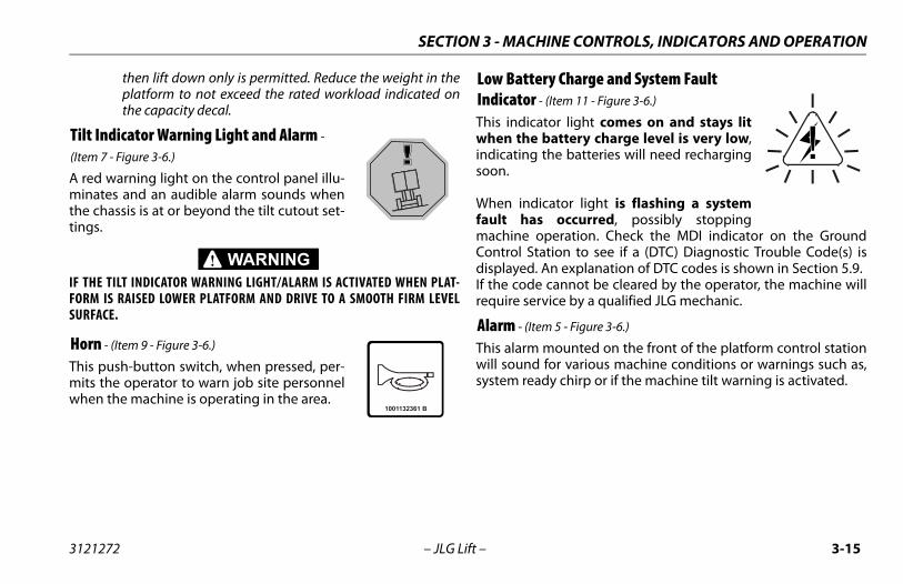
Tilt Indicator Warning Light and Alarm -
(Item 7 - Figure 3-6.)
A red warning light on the control panel illu-minates and an audible alarm sounds whenthe chassis is at or beyond the tilt cutout set-tings.
IF THE TILT INDICATOR WARNING LIGHT/ALARM IS ACTIVATED WHEN PLAT-FORM IS RAISED LOWER PLATFORM AND DRIVE TO A SMOOTH FIRM LEVELSURFACE.
Horn - (Item 9 - Figure 3-6.)
This push-button switch, when pressed, per-mits the operator to warn job site personnelwhen the machine is operating in the area.
Low Battery Charge and System Fault Indicator - (Item 11 - Figure 3-6.)
This indicator light comes on and stays litwhen the battery charge level is very low,indicating the batteries will need rechargingsoon.
When indicator light is flashing a systemfault has occurred, possibly stoppingmachine operation. Check the MDI indicator on the GroundControl Station to see if a (DTC) Diagnostic Trouble Code(s) isdisplayed. An explanation of DTC codes is shown in Section 5.9.If the code cannot be cleared by the operator, the machine willrequire service by a qualified JLG mechanic.
Alarm - (Item 5 - Figure 3-6.)
This alarm mounted on the front of the platform control stationwill sound for various machine conditions or warnings such as,system ready chirp or if the machine tilt warning is activated.
3121272 – JLG Lift – 3-15
SECTION 3 - MACHINE CONTROLS, INDICATORS AND OPERATION
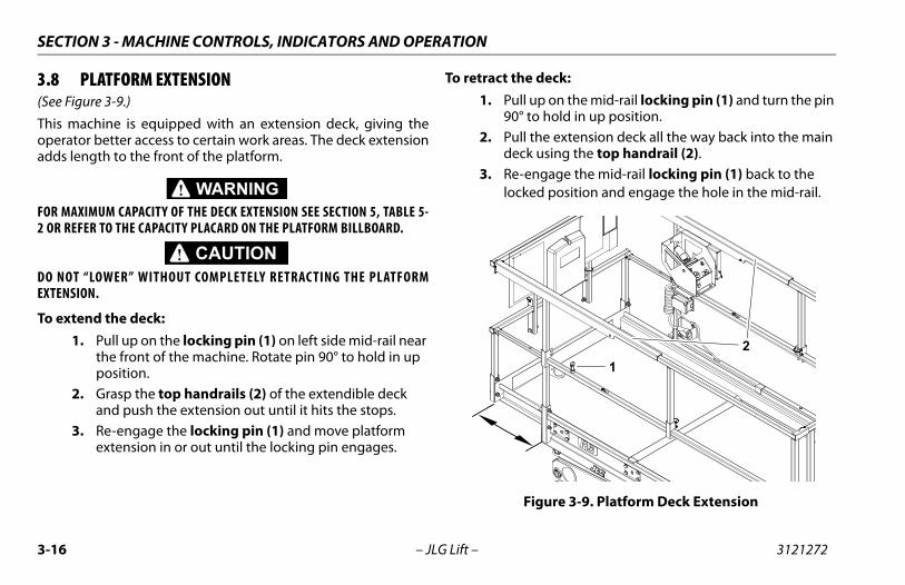
3.8 PLATFORM EXTENSION(See Figure 3-9.)
This machine is equipped with an extension deck, giving theoperator better access to certain work areas. The deck extensionadds length to the front of the platform.
FOR MAXIMUM CAPACITY OF THE DECK EXTENSION SEE SECTION 5, TABLE 5-2 OR REFER TO THE CAPACITY PLACARD ON THE PLATFORM BILLBOARD.
DO NOT “LOWER” WITHOUT COMPLETELY RETRAC TING THE PLATFORMEXTENSION.
To extend the deck:1. Pull up on the locking pin (1) on left side mid-rail near
the front of the machine. Rotate pin 90° to hold in up position.
2. Grasp the top handrails (2) of the extendible deck and push the extension out until it hits the stops.
3. Re-engage the locking pin (1) and move platform extension in or out until the locking pin engages.
To retract the deck:1. Pull up on the mid-rail locking pin (1) and turn the pin
90° to hold in up position.2. Pull the extension deck all the way back into the main
deck using the top handrail (2).3. Re-engage the mid-rail locking pin (1) back to the
locked position and engage the hole in the mid-rail.
Figure 3-9. Platform Deck Extension
12
3-16 – JLG Lift – 3121272
SECTION 3 - MACHINE CONTROLS, INDICATORS AND OPERATION
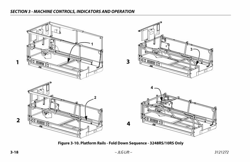
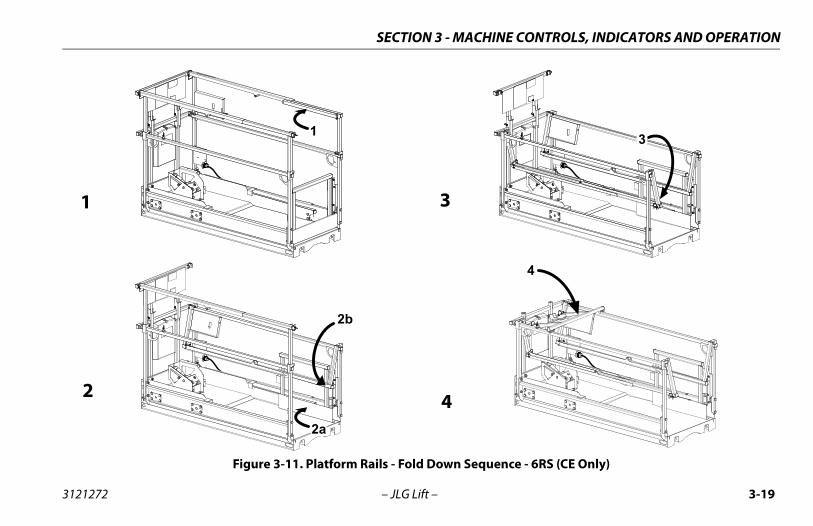
3.9 PLATFORM RAILS - FOLD-DOWN PROCEDURE - (3248RS/10RS and 6RS-CE Only)
(See Figure 3-10. and Figure 3-11.)
DO NOT RAISE PLATFORM WITH RAILS FOLDED DOWN. THE RAILS MUST BEIN THE UPRIGHT POSITION AND PROPERLY PINNED WHEN RAISING THEPLATFORM.
NOTE: The rails must only be folded down when the machine is inthe stowed (platform fully lowered) position.The platform control box should be removed from mountbefore the side rails are folded down.
The platform rails fold down from the mid rail only, except forthe rear gate rail.
NOTE: If equipped with the optional self-closing gate, the gatemust be held open while lowering the rear and side rails.
The platform rails fold down in the following sequence;(See Figure 3-10. and Figure 3-11.)
• First - pull pins, fold down rear gate rail (1).
NOTE: Front deck extension top rail pins must be removed anddeck extension top side rails slid towards rear of machinebefore lowering side rails. Place pins back in the extensionside top rails before folding main platform side rails down.
• Second - pull pins, fold down both side rails (2 & 3).
• Last - pull pins, fold down front platform extension rail(4).
1. To fold down each of the rails, remove the bail pins for that rail.
2. Taking a firm hold on the top rail, carefully lower until the top rail is fully folded in the down position.
3. To raise the rails back to the upright position, unfold the rails in the reverse sequence they were folded. Firmly pull the rails back up into position and replace the bail pins into the rails.
4. Retract the extension deck and set it’s lock pin.
AFTER THE RAILS HAVE BEEN FOLDED DOWN, USE EXTREME CAUTION WHENEXITING AND ENTERING THE PLATFORM. ENTER AND EXIT PLATFORM ONLYAT THE GATE AREA AND LADDER PROVIDED.
IF OPERATING (DRIVING) MACHINE WITH PLATFORM CONTROL STATIONFROM GROUND, WITH RAILS FOLDED, KEEP AT LEAST 3 FT. (1 M) DISTANCEFROM MACHINE.
3121272 – JLG Lift – 3-17
SECTION 3 - MACHINE CONTROLS, INDICATORS AND OPERATION
Figure 3-10. Platform Rails - Fold Down Sequence - 3248RS/10RS Only
1
1
3
3
2
2
4
4
3-18 – JLG Lift – 3121272
SECTION 3 - MACHINE CONTROLS, INDICATORS AND OPERATION
Figure 3-11. Platform Rails - Fold Down Sequence - 6RS (CE Only)
1
1
3
3
2b
2a
2
4
4
3121272 – JLG Lift – 3-19
SECTION 3 - MACHINE CONTROLS, INDICATORS AND OPERATION
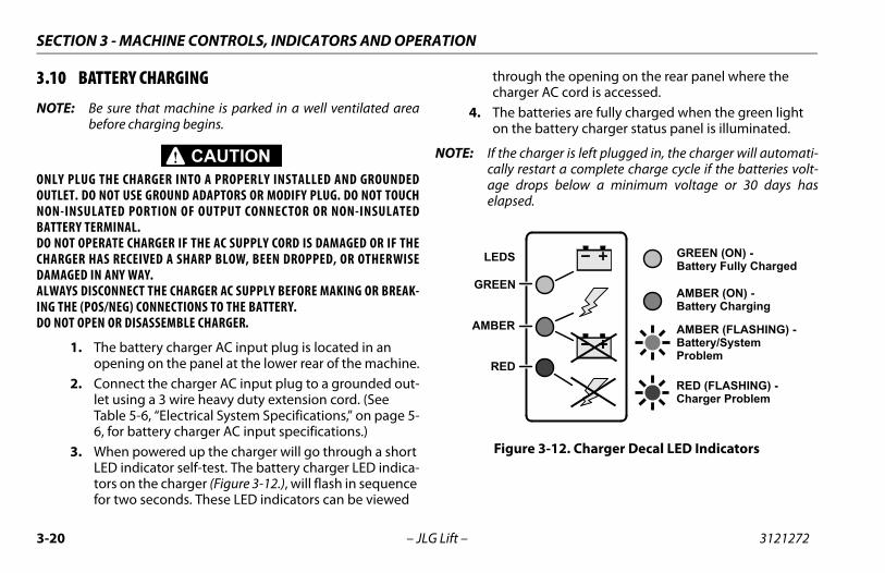
3.10 BATTERY CHARGING
NOTE: Be sure that machine is parked in a well ventilated areabefore charging begins.
ONLY PLUG THE CHARGER INTO A PROPERLY INSTALLED AND GROUNDEDOUTLET. DO NOT USE GROUND ADAPTORS OR MODIFY PLUG. DO NOT TOUCHNON-INSULATED PORTION OF OUTPUT CONNECTOR OR NON-INSULATEDBATTERY TERMINAL.DO NOT OPERATE CHARGER IF THE AC SUPPLY CORD IS DAMAGED OR IF THECHARGER HAS RECEIVED A SHARP BLOW, BEEN DROPPED, OR OTHERWISEDAMAGED IN ANY WAY.ALWAYS DISCONNECT THE CHARGER AC SUPPLY BEFORE MAKING OR BREAK-ING THE (POS/NEG) CONNECTIONS TO THE BATTERY.DO NOT OPEN OR DISASSEMBLE CHARGER.
1. The battery charger AC input plug is located in an opening on the panel at the lower rear of the machine.
2. Connect the charger AC input plug to a grounded out-let using a 3 wire heavy duty extension cord. (See Table 5-6, “Electrical System Specifications,” on page 5-6, for battery charger AC input specifications.)
3. When powered up the charger will go through a short LED indicator self-test. The battery charger LED indica-tors on the charger (Figure 3-12.), will flash in sequence for two seconds. These LED indicators can be viewed
through the opening on the rear panel where the charger AC cord is accessed.
4. The batteries are fully charged when the green light on the battery charger status panel is illuminated.
NOTE: If the charger is left plugged in, the charger will automati-cally restart a complete charge cycle if the batteries volt-age drops below a minimum voltage or 30 days haselapsed.
Figure 3-12. Charger Decal LED Indicators
GREEN (ON) -Battery Fully Charged
AMBER (ON) -Battery Charging
AMBER (FLASHING) -Battery/SystemProblem
RED (FLASHING) -Charger Problem
GREEN
AMBER
RED
LEDS
3-20 – JLG Lift – 3121272
SECTION 3 - MACHINE CONTROLS, INDICATORS AND OPERATION
Battery Charger Fault (LED Flash)
If a fault has occurred during battery charging, the (AMBER orRED) LED on the charger LED indicator (See Figure 3-12.) willflash corresponding to the fault which occurred. Refer to Table3-1 following for the charger LED flash codes and their meaning.
If required, further general and troubleshooting informationabout the battery charger can be found in the charger manufac-turers Owner’s Guide.
Table 3-1. Battery Charger Fault (LED Flash)
FLASHING LED FAULT REMEDY
AMBER Battery High VoltageUpon battery voltage >2.5V per cell @ startup, charger shall flash amber LED and not allow charging - Battery or System problem.
AMBER Battery Low VoltageUpon battery voltage <0.17V per cell @ startup, charger shall flash amber LED and not allow charging - Battery or System problem.
AMBER Failed Trickle to min VShould battery fail to reach 1.75V per cell charge shall flash an amber LED until char-ger is power cycled - Battery or System problem.
RED Charger Internal Fault Signals a hardware fault of the charger and shall indicate flashing red LED.
3121272 – JLG Lift – 3-21
SECTION 3 - MACHINE CONTROLS, INDICATORS AND OPERATION
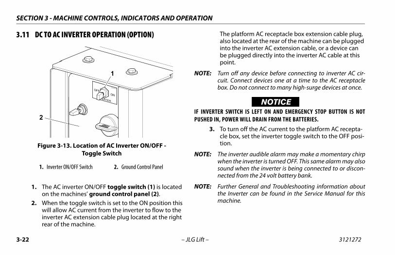
3.11 DC TO AC INVERTER OPERATION (OPTION)
1. The AC inverter ON/OFF toggle switch (1) is located on the machines’ ground control panel (2).
2. When the toggle switch is set to the ON position this will allow AC current from the inverter to flow to the inverter AC extension cable plug located at the right rear of the machine.
The platform AC receptacle box extension cable plug, also located at the rear of the machine can be plugged into the inverter AC extension cable, or a device can be plugged directly into the inverter AC cable at this point.
NOTE: Turn off any device before connecting to inverter AC cir-cuit. Connect devices one at a time to the AC receptaclebox. Do not connect to many high-surge devices at once.
NOTICEIF INVERTER SWITCH IS LEFT ON AND EMERGENCY STOP BUTTON IS NOTPUSHED IN, POWER WILL DRAIN FROM THE BATTERIES.
3. To turn off the AC current to the platform AC recepta-cle box, set the inverter toggle switch to the OFF posi-tion.
NOTE: The inverter audible alarm may make a momentary chirpwhen the inverter is turned OFF. This same alarm may alsosound when the inverter is being connected to or discon-nected from the 24 volt battery bank.
NOTE: Further General and Troubleshooting information aboutthe Inverter can be found in the Service Manual for thismachine.
Figure 3-13. Location of AC Inverter ON/OFF - Toggle Switch
1. Inverter ON/OFF Switch 2. Ground Control Panel
INVERTER
ONOFF
1001143010A
1
2
3-22 – JLG Lift – 3121272
SECTION 3 - MACHINE CONTROLS, INDICATORS AND OPERATION
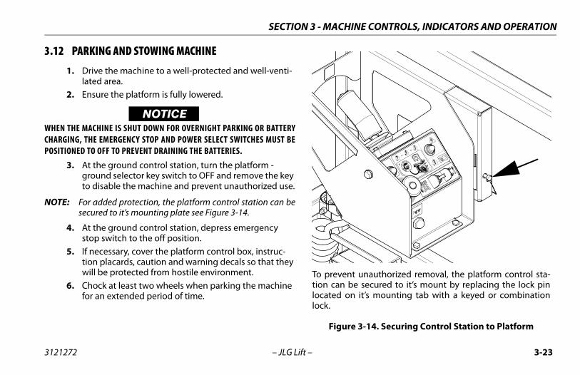
3.12 PARKING AND STOWING MACHINE
1. Drive the machine to a well-protected and well-venti-lated area.
2. Ensure the platform is fully lowered.
NOTICEWHEN THE MACHINE IS SHUT DOWN FOR OVERNIGHT PARKING OR BATTERYCHARGING, THE EMERGENCY STOP AND POWER SELECT SWITCHES MUST BEPOSITIONED TO OFF TO PREVENT DRAINING THE BATTERIES.
3. At the ground control station, turn the platform - ground selector key switch to OFF and remove the key to disable the machine and prevent unauthorized use.
NOTE: For added protection, the platform control station can besecured to it’s mounting plate see Figure 3-14.
4. At the ground control station, depress emergency stop switch to the off position.
5. If necessary, cover the platform control box, instruc-tion placards, caution and warning decals so that they will be protected from hostile environment.
6. Chock at least two wheels when parking the machine for an extended period of time.
To prevent unauthorized removal, the platform control sta-tion can be secured to it’s mount by replacing the lock pinlocated on it’s mounting tab with a keyed or combinationlock.
Figure 3-14. Securing Control Station to Platform
1001132362 B
12
3121272 – JLG Lift – 3-23
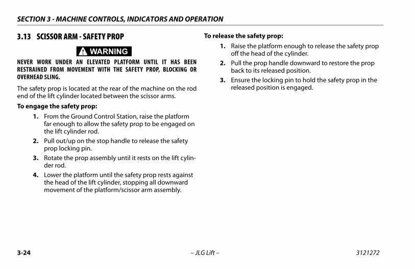
SECTION 3 - MACHINE CONTROLS, INDICATORS AND OPERATION
3.13 SCISSOR ARM - SAFETY PROP
NEVER WORK UNDER AN ELEVATED PLATFORM UNTIL IT HAS BEENRESTRAINED FROM MOVEMENT WITH THE SAFETY PROP, BLOCKING OROVERHEAD SLING.
The safety prop is located at the rear of the machine on the rodend of the lift cylinder located between the scissor arms.
To engage the safety prop:1. From the Ground Control Station, raise the platform
far enough to allow the safety prop to be engaged on the lift cylinder rod.
2. Pull out/up on the stop handle to release the safety prop locking pin.
3. Rotate the prop assembly until it rests on the lift cylin-der rod.
4. Lower the platform until the safety prop rests against the head of the lift cylinder, stopping all downward movement of the platform/scissor arm assembly.
To release the safety prop:1. Raise the platform enough to release the safety prop
off the head of the cylinder.2. Pull the prop handle downward to restore the prop
back to its released position.3. Ensure the locking pin to hold the safety prop in the
released position is engaged.
3-24 – JLG Lift – 3121272
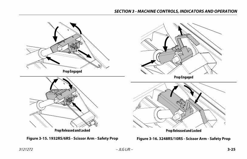
SECTION 3 - MACHINE CONTROLS, INDICATORS AND OPERATION
Prop Engaged
Prop Released and Locked
Figure 3-15. 1932RS/6RS - Scissor Arm - Safety Prop
Prop Engaged
Prop Released and Locked
Figure 3-16. 3248RS/10RS - Scissor Arm - Safety Prop
3121272 – JLG Lift – 3-25
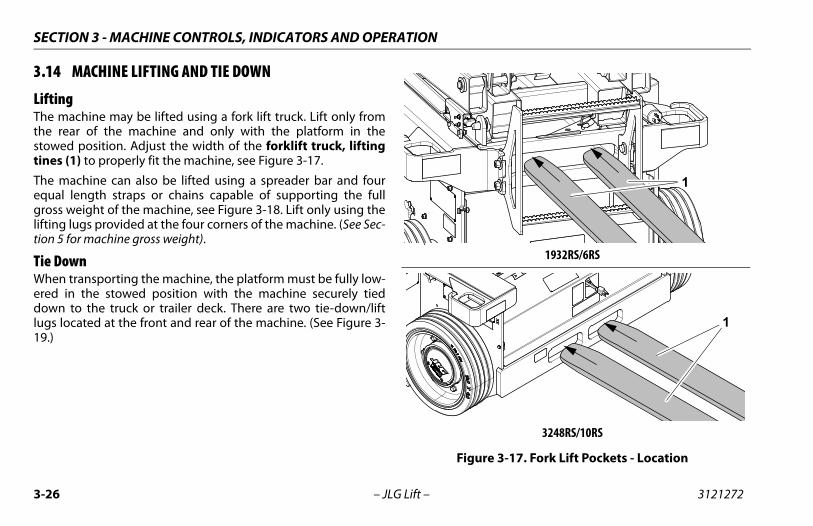
SECTION 3 - MACHINE CONTROLS, INDICATORS AND OPERATION
3.14 MACHINE LIFTING AND TIE DOWN
LiftingThe machine may be lifted using a fork lift truck. Lift only fromthe rear of the machine and only with the platform in thestowed position. Adjust the width of the forklift truck, liftingtines (1) to properly fit the machine, see Figure 3-17.
The machine can also be lifted using a spreader bar and fourequal length straps or chains capable of supporting the fullgross weight of the machine, see Figure 3-18. Lift only using thelifting lugs provided at the four corners of the machine. (See Sec-tion 5 for machine gross weight).
Tie DownWhen transporting the machine, the platform must be fully low-ered in the stowed position with the machine securely tieddown to the truck or trailer deck. There are two tie-down/liftlugs located at the front and rear of the machine. (See Figure 3-19.)
1932RS/6RS
3248RS/10RS
Figure 3-17. Fork Lift Pockets - Location
1
1
3-26 – JLG Lift – 3121272
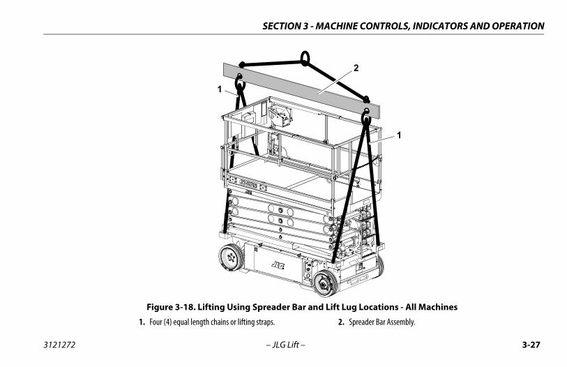
SECTION 3 - MACHINE CONTROLS, INDICATORS AND OPERATION
Figure 3-18. Lifting Using Spreader Bar and Lift Lug Locations - All Machines
1. Four (4) equal length chains or lifting straps. 2. Spreader Bar Assembly.
1
2
1
3121272 – JLG Lift – 3-27
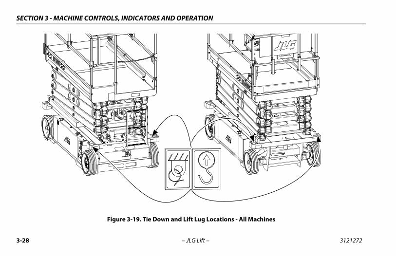
SECTION 3 - MACHINE CONTROLS, INDICATORS AND OPERATION
Figure 3-19. Tie Down and Lift Lug Locations - All Machines
3-28 – JLG Lift – 3121272
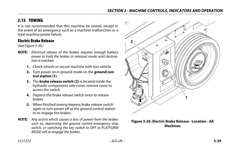
SECTION 3 - MACHINE CONTROLS, INDICATORS AND OPERATION
3.15 TOWINGIt is not recommended that this machine be towed, except inthe event of an emergency such as a machine malfunction or atotal machine power failure.
Electric Brake Release(See Figure 3-20.)
NOTE: Electrical release of the brakes requires enough batterypower to hold the brakes in released mode until destina-tion is reached.
1. Chock wheels or secure machine with tow vehicle.2. Turn power on in ground mode on the ground con-
trol station (1).3. The brake release switch (2) is located inside the
hydraulic components side cover, remove cover to access the switch.
4. Depress the brake release switch once to release brakes.
5. When finished towing depress brake release switch again or turn power off at the ground control station to re-engage the brakes.
NOTE: Any action which causes a loss of power from the brakessuch as, depressing the ground control emergency stopswitch, or switching the key switch to OFF or PLATFORMMODE will re-engage the brakes.
Figure 3-20. Electric Brake Release - Location - All Machines
2
1
3121272 – JLG Lift – 3-29
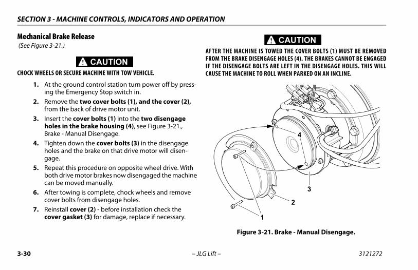
SECTION 3 - MACHINE CONTROLS, INDICATORS AND OPERATION
Mechanical Brake Release (See Figure 3-21.)
CHOCK WHEELS OR SECURE MACHINE WITH TOW VEHICLE.
1. At the ground control station turn power off by press-ing the Emergency Stop switch in.
2. Remove the two cover bolts (1), and the cover (2), from the back of drive motor unit.
3. Insert the cover bolts (1) into the two disengage holes in the brake housing (4), see Figure 3-21., Brake - Manual Disengage.
4. Tighten down the cover bolts (3) in the disengage holes and the brake on that drive motor will disen-gage.
5. Repeat this procedure on opposite wheel drive. With both drive motor brakes now disengaged the machine can be moved manually.
6. After towing is complete, chock wheels and remove cover bolts from disengage holes.
7. Reinstall cover (2) - before installation check the cover gasket (3) for damage, replace if necessary.
AFTER THE MACHINE IS TOWED THE COVER BOLTS (1) MUST BE REMOVEDFROM THE BRAKE DISENGAGE HOLES (4). THE BRAKES CANNOT BE ENGAGEDIF THE DISENGAGE BOLTS ARE LEFT IN THE DISENGAGE HOLES. THIS WILLCAUSE THE MACHINE TO ROLL WHEN PARKED ON AN INCLINE.
Figure 3-21. Brake - Manual Disengage.
1
2
4
3
3-30 – JLG Lift – 3121272
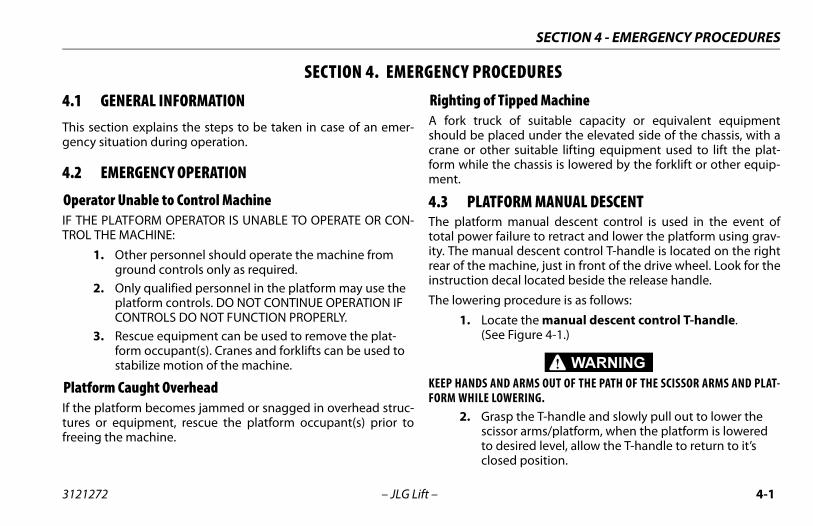
SECTION 4 - EMERGENCY PROCEDURES
SECTION 4. EMERGENC Y PROCEDURES4.1 GENERAL INFORMATIONThis section explains the steps to be taken in case of an emer-gency situation during operation.
4.2 EMERGENCY OPERATION
Operator Unable to Control MachineIF THE PLATFORM OPERATOR IS UNABLE TO OPERATE OR CON-TROL THE MACHINE:
1. Other personnel should operate the machine from ground controls only as required.
2. Only qualified personnel in the platform may use the platform controls. DO NOT CONTINUE OPERATION IF CONTROLS DO NOT FUNCTION PROPERLY.
3. Rescue equipment can be used to remove the plat-form occupant(s). Cranes and forklifts can be used to stabilize motion of the machine.
Platform Caught OverheadIf the platform becomes jammed or snagged in overhead struc-tures or equipment, rescue the platform occupant(s) prior tofreeing the machine.
Righting of Tipped MachineA fork truck of suitable capacity or equivalent equipmentshould be placed under the elevated side of the chassis, with acrane or other suitable lifting equipment used to lift the plat-form while the chassis is lowered by the forklift or other equip-ment.
4.3 PLATFORM MANUAL DESCENTThe platform manual descent control is used in the event oftotal power failure to retract and lower the platform using grav-ity. The manual descent control T-handle is located on the rightrear of the machine, just in front of the drive wheel. Look for theinstruction decal located beside the release handle.
The lowering procedure is as follows:
1. Locate the manual descent control T-handle.(See Figure 4-1.)
KEEP HANDS AND ARMS OUT OF THE PATH OF THE SCISSOR ARMS AND PLAT-FORM WHILE LOWERING.
2. Grasp the T-handle and slowly pull out to lower the scissor arms/platform, when the platform is lowered to desired level, allow the T-handle to return to it’s closed position.
3121272 – JLG Lift – 4-1
SECTION 4 - EMERGENCY PROCEDURES
4.4 INCIDENT NOTIFICATIONJLG Industries, Inc. must be notified immediately of any incidentinvolving a JLG product. Even if no injury or property damage isevident, JLG must be contacted by telephone and providedwith all necessary details.
USA: 877-JLG-SAFE (554-7233)
EUROPE: (44) 1 698 811005
AUSTRALIA: (61) 2 65 811111
E-mail: [email protected]
Failure to notify the manufacturer of an incident involving a JLGIndustries product within 48 hours of such an occurrence mayvoid any warranty consideration on that particular machine.
NOTICEFOLLOWING ANY INCIDENT, THOROUGHLY INSPECT THE MACHINE. DO NOTELEVATE PLATFORM UNTIL YOU ARE SURE THAT ALL DAMAGE HAS BEENREPAIRED, AND THAT ALL CONTROLS ARE OPERATING CORRECTLY. TEST ALLFUNCTIONS FIRST FROM THE GROUND CONTROL STATION, THEN FROM THEPLATFORM CONTROL CONSOLE.
Figure 4-1. Location of Manual Descent Control(Right Rear of Machine - All Machines)
4-2 – JLG Lift – 3121272
SECTION 5 - GENERAL SPECIFICATIONS AND MAINTENANCE
SECTION 5. GENERAL SPECIFICATIONS AND MAINTENANCE
5.1 INTRODUCTIONThis section of the manual provides additional necessary infor-mation to the operator for proper operation and maintenanceof this machine.
The maintenance portion of this section is intended as informa-tion to assist the machine operator to perform daily mainte-nance tasks only, and does not replace the more thoroughPreventive Maintenance and Inspection Schedule included inthe Service and Maintenance Manual.
Other Publications Available Specific to this Machine: Service and Maintenance Manual......................................3121273
Illustrated Parts Manual .........................................................3121274
3121272 – JLG Lift – 5-1
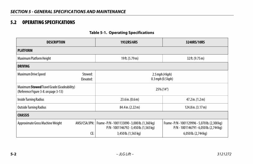
SECTION 5 - GENERAL SPECIFICATIONS AND MAINTENANCE
5.2 OPERATING SPECIFICATIONS
Table 5-1. Operating Specifications
DESCRIPTION 1932RS/6RS 3248RS/10RS
PLATFORM
Maximum Platform Height 19 ft. (5.79 m) 32 ft. (9.75 m)
DRIVING
Maximum Drive Speed Stowed:Elevated:
2.5 mph (4 kph)0.3 mph (0.5 kph)
Maximum Stowed Travel Grade (Gradeability)(Reference Figure 3-8. on page 3-13) 25% (14°)
Inside Turning Radius 23.6 in. (0.6 m) 47.2 in. (1.2 m)
Outside Turning Radius 84.4 in. (2.22 m) 124.8 in. (3.17 m)
CHASSIS
Approximate Gross Machine Weight ANSI/CSA/JPN:
CE:
Frame - P/N - 1001133090 - 3,000 lb. (1,360 kg) P/N - 1001146792 - 3,450 lb. (1,565 kg)
3,450 lb. (1,565 kg)
Frame - P/N - 1001129996 - 5,070 lb. (2,300 kg) P/N - 1001146791 - 6,050 lb. (2,744 kg)
6,050 lb. (2,744 kg)
5-2 – JLG Lift – 3121272
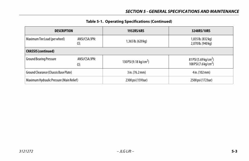
SECTION 5 - GENERAL SPECIFICATIONS AND MAINTENANCE
Maximum Tire Load (per wheel) ANSI/CSA/JPN:CE: 1,365 lb. (620 kg) 1,835 lb. (832 kg)
2,070 lb. (940 kg)
CHASSIS (continued)
Ground Bearing Pressure ANSI/CSA/JPN:CE:
130 PSI (9.18 kg/cm2) 81 PSI (5.69 kg/cm2)108 PSI (7.6 kg/cm2)
Ground Clearance (Chassis Base Plate) 3 in. (76.2 mm) 4 in. (102 mm)
Maximum Hydraulic Pressure (Main Relief) 2300 psi (159 bar) 2500 psi (172 bar)
Table 5-1. Operating Specifications (Continued)
DESCRIPTION 1932RS/6RS 3248RS/10RS
3121272 – JLG Lift – 5-3
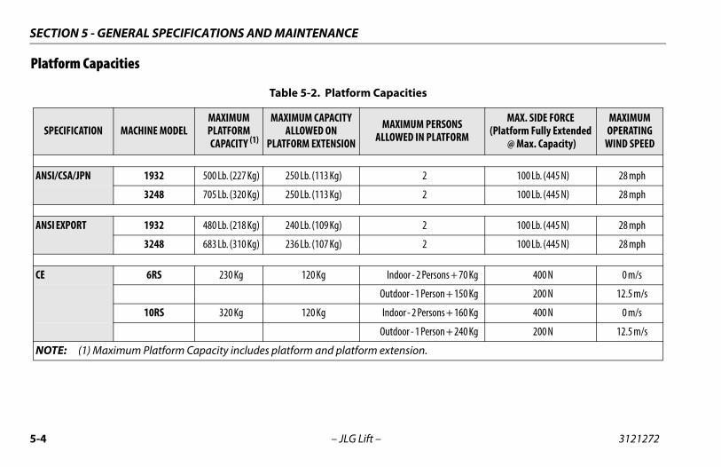
SECTION 5 - GENERAL SPECIFICATIONS AND MAINTENANCE
Platform Capacities
Table 5-2. Platform Capacities
SPECIFICATION MACHINE MODELMAXIMUMPLATFORM
CAPACITY (1)
MAXIMUM CAPACITY ALLOWED ON
PLATFORM EXTENSION
MAXIMUM PERSONSALLOWED IN PLATFORM
MAX. SIDE FORCE(Platform Fully Extended
@ Max. Capacity)
MAXIMUM OPERATING
WIND SPEED
ANSI/CSA/JPN 1932 500 Lb. (227 Kg) 250 Lb. (113 Kg) 2 100 Lb. (445 N) 28 mph
3248 705 Lb. (320 Kg) 250 Lb. (113 Kg) 2 100 Lb. (445 N) 28 mph
ANSI EXPORT 1932 480 Lb. (218 Kg) 240 Lb. (109 Kg) 2 100 Lb. (445 N) 28 mph
3248 683 Lb. (310 Kg) 236 Lb. (107 Kg) 2 100 Lb. (445 N) 28 mph
CE 6RS 230 Kg 120 Kg Indoor - 2 Persons + 70 Kg 400 N 0 m/s
Outdoor - 1 Person + 150 Kg 200 N 12.5 m/s
10RS 320 Kg 120 Kg Indoor - 2 Persons + 160 Kg 400 N 0 m/s
Outdoor - 1 Person + 240 Kg 200 N 12.5 m/s
NOTE: (1) Maximum Platform Capacity includes platform and platform extension.
5-4 – JLG Lift – 3121272
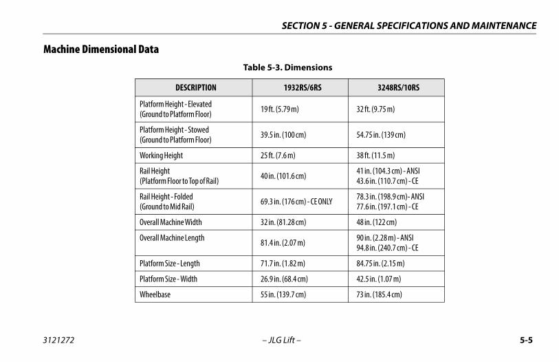
SECTION 5 - GENERAL SPECIFICATIONS AND MAINTENANCE
Machine Dimensional DataTable 5-3. Dimensions
DESCRIPTION 1932RS/6RS 3248RS/10RS
Platform Height - Elevated(Ground to Platform Floor) 19 ft. (5.79 m) 32 ft. (9.75 m)
Platform Height - Stowed(Ground to Platform Floor) 39.5 in. (100 cm) 54.75 in. (139 cm)
Working Height 25 ft. (7.6 m) 38 ft. (11.5 m)
Rail Height(Platform Floor to Top of Rail) 40 in. (101.6 cm) 41 in. (104.3 cm) - ANSI
43.6 in. (110.7 cm) - CE
Rail Height - Folded(Ground to Mid Rail) 69.3 in. (176 cm) - CE ONLY 78.3 in. (198.9 cm)- ANSI
77.6 in. (197.1 cm) - CE
Overall Machine Width 32 in. (81.28 cm) 48 in. (122 cm)
Overall Machine Length 81.4 in. (2.07 m) 90 in. (2.28 m) - ANSI94.8 in. (240.7 cm) - CE
Platform Size - Length 71.7 in. (1.82 m) 84.75 in. (2.15 m)
Platform Size - Width 26.9 in. (68.4 cm) 42.5 in. (1.07 m)
Wheelbase 55 in. (139.7 cm) 73 in. (185.4 cm)
3121272 – JLG Lift – 5-5
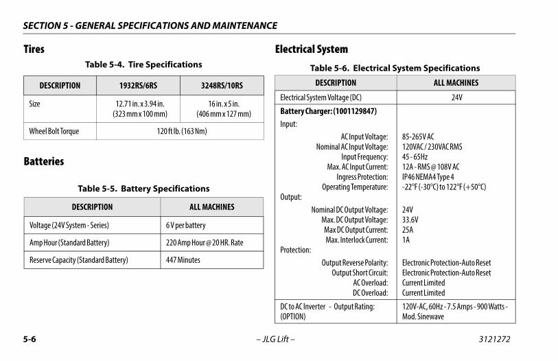
SECTION 5 - GENERAL SPECIFICATIONS AND MAINTENANCE
Tires
Batteries
Electrical SystemTable 5-4. Tire Specifications
DESCRIPTION 1932RS/6RS 3248RS/10RS
Size 12.71 in. x 3.94 in.(323 mm x 100 mm)
16 in. x 5 in.(406 mm x 127 mm)
Wheel Bolt Torque 120 ft lb. (163 Nm)
Table 5-5. Battery Specifications
DESCRIPTION ALL MACHINES
Voltage (24V System - Series) 6 V per battery
Amp Hour (Standard Battery) 220 Amp Hour @ 20 HR. Rate
Reserve Capacity (Standard Battery) 447 Minutes
Table 5-6. Electrical System Specifications
DESCRIPTION ALL MACHINES
Electrical System Voltage (DC) 24V
Battery Charger: (1001129847)Input:
AC Input Voltage:Nominal AC Input Voltage:
Input Frequency:Max. AC Input Current:
Ingress Protection:Operating Temperature:
Output:Nominal DC Output Voltage:
Max. DC Output Voltage:Max DC Output Current:Max. Interlock Current:
Protection:Output Reverse Polarity:
Output Short Circuit:AC Overload:DC Overload:
85-265V AC120VAC / 230VAC RMS45 - 65Hz12A - RMS @ 108V ACIP46 NEMA4 Type 4-22°F (-30°C) to 122°F (+50°C)
24V33.6V25A1A
Electronic Protection-Auto ResetElectronic Protection-Auto ResetCurrent LimitedCurrent Limited
DC to AC Inverter - Output Rating:(OPTION)
120V-AC, 60Hz - 7.5 Amps - 900 Watts - Mod. Sinewave
5-6 – JLG Lift – 3121272
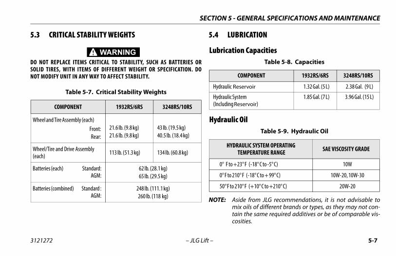
SECTION 5 - GENERAL SPECIFICATIONS AND MAINTENANCE
5.3 CRITICAL STABILITY WEIGHTS
DO NOT REPLACE ITEMS CRITICAL TO STABILITY, SUCH AS BATTERIES ORSOLID TIRES, WITH ITEMS OF DIFFERENT WEIGHT OR SPECIFICATION. DONOT MODIFY UNIT IN ANY WAY TO AFFECT STABILITY.
5.4 LUBRICATION
Lubrication Capacities
Hydraulic Oil
NOTE: Aside from JLG recommendations, it is not advisable tomix oils of different brands or types, as they may not con-tain the same required additives or be of comparable vis-cosities.
Table 5-7. Critical Stability Weights
COMPONENT 1932RS/6RS 3248RS/10RS
Wheel and Tire Assembly (each)Front:Rear:
21.6 lb. (9.8 kg)21.6 lb. (9.8 kg)
43 lb. (19.5 kg)40.5 lb. (18.4 kg)
Wheel/Tire and Drive Assembly (each) 113 lb. (51.3 kg) 134 lb. (60.8 kg)
Batteries (each) Standard:AGM:
62 lb. (28.1 kg)65 lb. (29.5 kg)
Batteries (combined) Standard :AGM:
248 lb. (111.1 kg)260 lb. (118 kg)
Table 5-8. Capacities
COMPONENT 1932RS/6RS 3248RS/10RS
Hydraulic Reservoir 1.32 Gal. (5 L) 2.38 Gal. (9 L)
Hydraulic System(Including Reservoir)
1.85 Gal. (7 L) 3.96 Gal. (15 L)
Table 5-9. Hydraulic Oil
HYDRAULIC SYSTEM OPERATING TEMPERATURE RANGE SAE VISCOSITY GRADE
0° F to +23° F (-18° C to -5° C) 10W
0° F to 210° F (-18° C to + 99° C) 10W-20, 10W-30
50° F to 210° F (+10° C to +210° C) 20W-20
3121272 – JLG Lift – 5-7
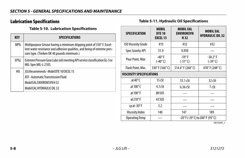
SECTION 5 - GENERAL SPECIFICATIONS AND MAINTENANCE
Lubrication SpecificationsTable 5-10. Lubrication Specifications
KEY SPECIFICATIONS
MPG Multipurpose Grease having a minimum dripping point of 350° F. Excel-lent water resistance and adhesive qualities, and being of extreme pres-sure type. (Timken OK 40 pounds minimum.)
EPGL Extreme Pressure Gear Lube (oil) meeting API service classification GL-5 or MIL-Spec MIL-L-2105.
HO JLG Recommends - Mobil DTE 10 EXCEL 15ATF - Automatic Transmission FluidMobil EAL ENVIRONSYN H 32Mobil EAL HYDRAULIC OIL 32
Table 5-11. Hydraulic Oil Specifications
SPECIFICATIONMOBILDTE 10
EXCEL 15
MOBIL EAL ENVIRONSYN
H 32
MOBIL EAL HYDRAULIC OIL 32
ISO Viscosity Grade #15 #32 #32
Spec Gravity API 31.9 0.950 —
Pour Point, Max -40° F(-40° C)
-59° F(-51° C)
-38.2° F (-39° C)
Flash Point, Min. 330° F (166° C) 514.4° F (268° C) 478° F (248° C)
VISCOSITY SPECIFICATIONSat 40° C 15 cSt 33.1 cSt 32 cSt
at 100° C 4.1 cSt 6.36 cSt 7 cSt
at 100° F 80 SUS — —
at 210° F 43 SUS — —
cp at -30° F 3.2 — —
Viscosity Index 140 147 189Operating Temp — -20° F (-29° C) to 200° F (93° C)
1001102685_3
5-8 – JLG Lift – 3121272
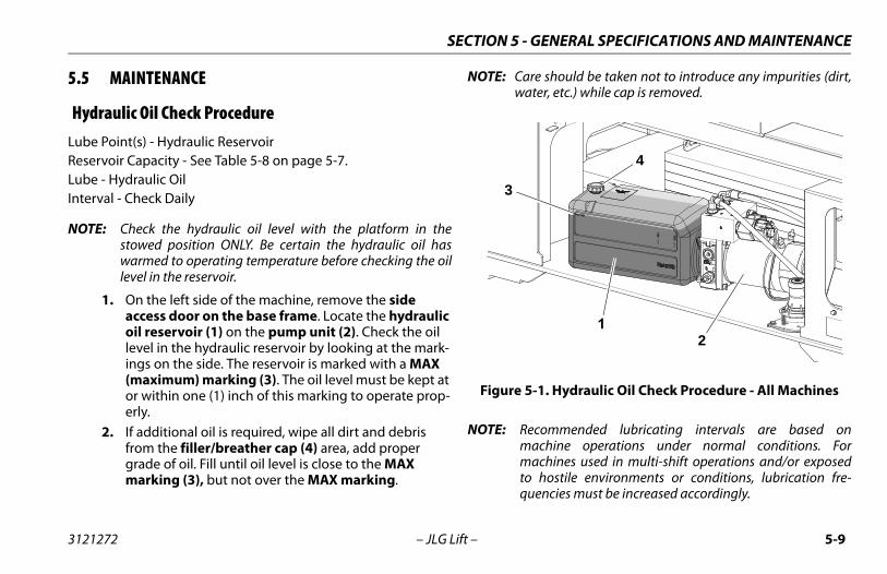
SECTION 5 - GENERAL SPECIFICATIONS AND MAINTENANCE
5.5 MAINTENANCE
Hydraulic Oil Check ProcedureLube Point(s) - Hydraulic ReservoirReservoir Capacity - See Table 5-8 on page 5-7.Lube - Hydraulic OilInterval - Check Daily
NOTE: Check the hydraulic oil level with the platform in thestowed position ONLY. Be certain the hydraulic oil haswarmed to operating temperature before checking the oillevel in the reservoir.
1. On the left side of the machine, remove the side access door on the base frame. Locate the hydraulic oil reservoir (1) on the pump unit (2). Check the oil level in the hydraulic reservoir by looking at the mark-ings on the side. The reservoir is marked with a MAX (maximum) marking (3). The oil level must be kept at or within one (1) inch of this marking to operate prop-erly.
2. If additional oil is required, wipe all dirt and debris from the filler/breather cap (4) area, add proper grade of oil. Fill until oil level is close to the MAX marking (3), but not over the MAX marking.
NOTE: Care should be taken not to introduce any impurities (dirt,water, etc.) while cap is removed.
NOTE: Recommended lubricating intervals are based onmachine operations under normal conditions. Formachines used in multi-shift operations and/or exposedto hostile environments or conditions, lubrication fre-quencies must be increased accordingly.
Figure 5-1. Hydraulic Oil Check Procedure - All Machines
12
3
4
3121272 – JLG Lift – 5-9
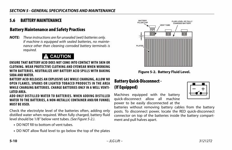
SECTION 5 - GENERAL SPECIFICATIONS AND MAINTENANCE
5.6 BATTERY MAINTENANCE
Battery Maintenance and Safety Practices
NOTE: These instructions are for unsealed (wet) batteries only.if machine is equipped with sealed batteries, no mainte-nance other than cleaning corroded battery terminals isrequired.
ENSURE THAT BATTERY ACID DOES NOT COME INTO CONTACT WITH SKIN ORCLOTHING. WEAR PROTECTIVE CLOTHING AND EYEWEAR WHEN WORKINGWITH BATTERIES. NEUTRALIZE ANY BATTERY ACID SPILLS WITH BAKINGSODA AND WATER.BATTERY ACID RELEASES AN EXPLOSIVE GAS WHILE CHARGING, ALLOW NOOPEN FLAMES, SPARKS OR LIGHTED TOBACCO PRODUC TS IN THE AREAWHILE CHARGING BATTERIES. CHARGE BATTERIES ONLY IN A WELL VENTI-LATED AREA.ADD ONLY DISTILLED WATER TO BATTERIES. WHEN ADDING DISTILLEDWATER TO THE BATTERIES, A NON-METALLIC CONTAINER AND/OR FUNNELMUST BE USED.
Check the electrolyte level of the batteries often, adding onlydistilled water when required. When fully charged, battery fluidlevel should be 1/8" below vent tubes. (See Figure 5-2.).
• DO NOT fill to bottom of vent tubes.
• DO NOT allow fluid level to go below the top of the plates
Battery Quick-Disconnect -(If Equipped)Machines equipped with the batteryquick-disconnect allow all machinepower to be easily disconnected at thebatteries without removing battery cables from the batteryposts. To disconnect power, locate the RED quick-disconnectconnector on top of the batteries inside the battery compart-ment and pull halves apart.
Figure 5-2. Battery Fluid Level.
1/8 "
BATTERYFILLER CAP
FLUID LEVEL OF FULLY
CHARGED BATTERY VENT TUBE
PLATES
1706740A
5-10 – JLG Lift – 3121272
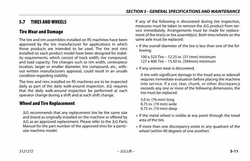
SECTION 5 - GENERAL SPECIFICATIONS AND MAINTENANCE
5.7 TIRES AND WHEELS
Tire Wear and DamageThe tire and rim assemblies installed on RS machines have beenapproved by the tire manufacturer for applications in whichthose products are intended to be used. The tire and rimsinstalled on each product model have been designed for stabil-ity requirements, which consist of track width, tire compound,and load capacity. Tire changes such as rim width, centerpiecelocation, larger or smaller diameter, tire compound, etc., with-out written manufacturers approval, could result in an unsafecondition regarding stability.
The tires and rims installed on RS machines are to be inspecteddaily as part of the daily walk-around inspection. JLG requiresthat the daily walk-around inspection be performed at eachoperator change during a shift and at each shift change.
Wheel and Tire Replacement
JLG recommends that any replacement tire be the same sizeand brand as originally installed on the machine or offered byJLG as an approved replacement. Please refer to the JLG PartsManual for the part number of the approved tires for a partic-ular machine model.
If any of the following is discovered during tire inspection,measures must be taken to remove the JLG product from ser-vice immediately. Arrangements must be made for replace-ment of the tire(s) or tire assembly(s). Both tires/wheels on thesame axle must be replaced:
• If the overall diameter of the tire is less than one of the fol-lowing:
100 x 323 Tire – 12.25 in. (311mm) minimum127 x 406 Tire – 15.50 in. (394mm) minimum
• If any uneven wear is discovered.
A tire with significant damage in the tread area or sidewallrequires immediate evaluation before placing the machineinto service. If a cut, tear, chunk, or other discrepancyexceeds any one or more of the following dimensions, thetire must be replaced:
3.0 in. (76 mm) long0.75 in. (19 mm) wide0.75 in. (19 mm) deep
• If the metal wheel is visible at any point through the treadarea of the tire.
• If more than one discrepancy exists in any quadrant of thewheel (within 90 degrees of one another).
3121272 – JLG Lift – 5-11
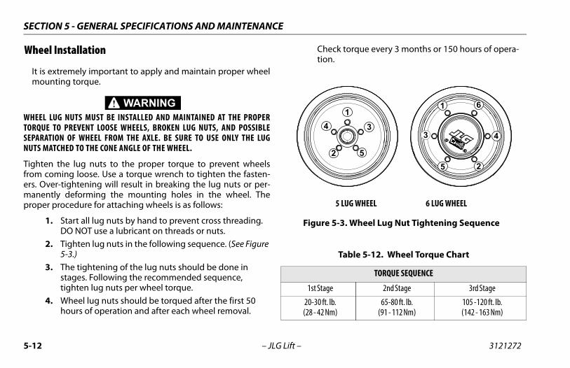
SECTION 5 - GENERAL SPECIFICATIONS AND MAINTENANCE
Wheel Installation
It is extremely important to apply and maintain proper wheelmounting torque.
WHEEL LUG NUTS MUST BE INSTALLED AND MAINTAINED AT THE PROPERTORQUE TO PREVENT LOOSE WHEELS, BROKEN LUG NUTS, AND POSSIBLESEPARATION OF WHEEL FROM THE AXLE. BE SURE TO USE ONLY THE LUGNUTS MATCHED TO THE CONE ANGLE OF THE WHEEL.
Tighten the lug nuts to the proper torque to prevent wheelsfrom coming loose. Use a torque wrench to tighten the fasten-ers. Over-tightening will result in breaking the lug nuts or per-manently deforming the mounting holes in the wheel. Theproper procedure for attaching wheels is as follows:
1. Start all lug nuts by hand to prevent cross threading. DO NOT use a lubricant on threads or nuts.
2. Tighten lug nuts in the following sequence. (See Figure 5-3.)
3. The tightening of the lug nuts should be done in stages. Following the recommended sequence, tighten lug nuts per wheel torque.
4. Wheel lug nuts should be torqued after the first 50 hours of operation and after each wheel removal.
Check torque every 3 months or 150 hours of opera-tion.
5 LUG WHEEL 6 LUG WHEEL
Figure 5-3. Wheel Lug Nut Tightening Sequence
Table 5-12. Wheel Torque Chart
TORQUE SEQUENCE
1st Stage 2nd Stage 3rd Stage
20-30 ft. lb.(28 - 42 Nm)
65-80 ft. lb.(91 - 112 Nm)
105 -120 ft. lb.(142 - 163 Nm)
1
2
34
52
3 4
6
5
1
5-12 – JLG Lift – 3121272
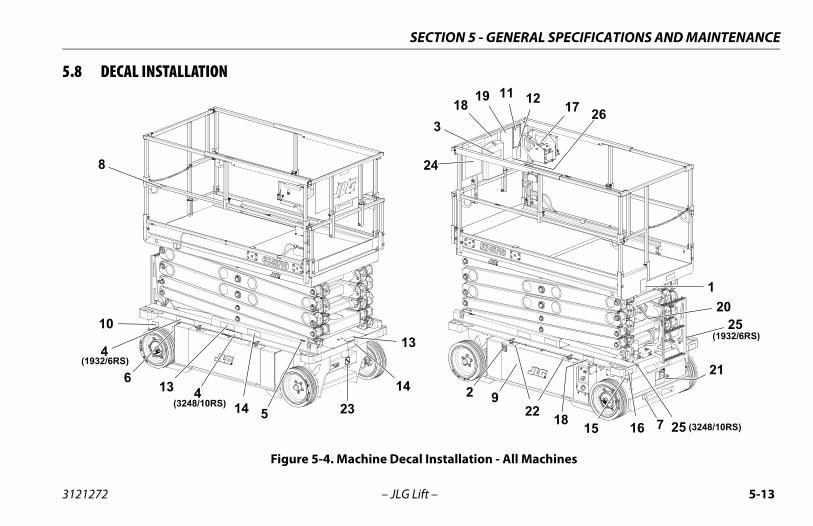
SECTION 5 - GENERAL SPECIFICATIONS AND MAINTENANCE
5.8 DECAL INSTALLATION
Figure 5-4. Machine Decal Installation - All Machines
3
1
25
6
7
9
10
11 12
13
14
16
1719
21
20
22
24
25(1932/6RS)
25 (3248/10RS)
8
15
41314
26
18
18
23(3248/10RS)
4(1932/6RS)
3121272 – JLG Lift – 5-13
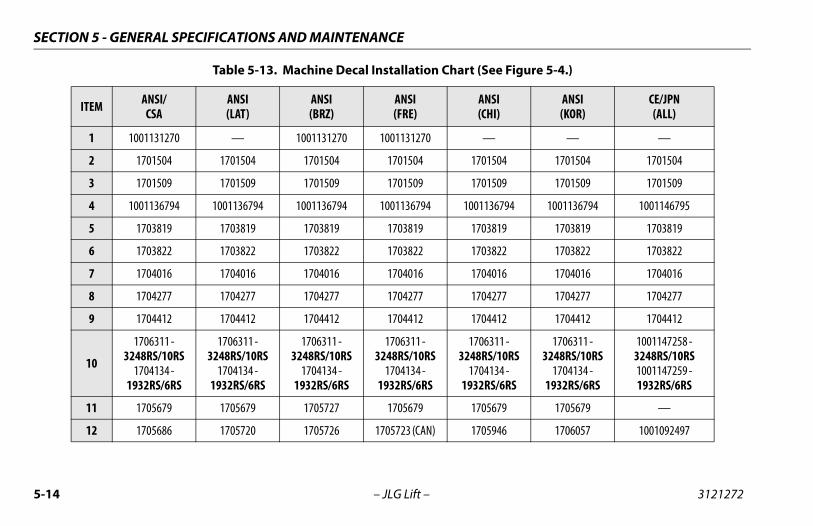
SECTION 5 - GENERAL SPECIFICATIONS AND MAINTENANCE
Table 5-13. Machine Decal Installation Chart (See Figure 5-4.)
ITEM ANSI/CSA
ANSI(LAT)
ANSI(BRZ)
ANSI(FRE)
ANSI(CHI)
ANSI(KOR)
CE/JPN(ALL)
1 1001131270 — 1001131270 1001131270 — — —
2 1701504 1701504 1701504 1701504 1701504 1701504 1701504
3 1701509 1701509 1701509 1701509 1701509 1701509 1701509
4 1001136794 1001136794 1001136794 1001136794 1001136794 1001136794 1001146795
5 1703819 1703819 1703819 1703819 1703819 1703819 1703819
6 1703822 1703822 1703822 1703822 1703822 1703822 1703822
7 1704016 1704016 1704016 1704016 1704016 1704016 1704016
8 1704277 1704277 1704277 1704277 1704277 1704277 1704277
9 1704412 1704412 1704412 1704412 1704412 1704412 1704412
10
1706311 -3248RS/10RS
1704134 - 1932RS/6RS
1706311 -3248RS/10RS
1704134 - 1932RS/6RS
1706311 -3248RS/10RS
1704134 - 1932RS/6RS
1706311 -3248RS/10RS
1704134 - 1932RS/6RS
1706311 -3248RS/10RS
1704134 - 1932RS/6RS
1706311 -3248RS/10RS
1704134 - 1932RS/6RS
1001147258 -3248RS/10RS1001147259 - 1932RS/6RS
11 1705679 1705679 1705727 1705679 1705679 1705679 —
12 1705686 1705720 1705726 1705723 (CAN) 1705946 1706057 1001092497
5-14 – JLG Lift – 3121272
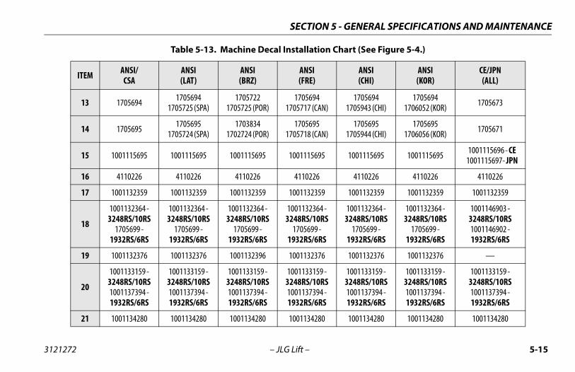
SECTION 5 - GENERAL SPECIFICATIONS AND MAINTENANCE
13 1705694 17056941705725 (SPA)
17057221705725 (POR)
17056941705717 (CAN)
17056941705943 (CHI)
17056941706052 (KOR) 1705673
14 1705695 17056951705724 (SPA)
17038341702724 (POR)
17056951705718 (CAN)
17056951705944 (CHI)
17056951706056 (KOR) 1705671
15 1001115695 1001115695 1001115695 1001115695 1001115695 1001115695 1001115696 - CE1001115697- JPN
16 4110226 4110226 4110226 4110226 4110226 4110226 4110226
17 1001132359 1001132359 1001132359 1001132359 1001132359 1001132359 1001132359
18
1001132364 -3248RS/10RS
1705699 -1932RS/6RS
1001132364 -3248RS/10RS
1705699 -1932RS/6RS
1001132364 -3248RS/10RS
1705699 -1932RS/6RS
1001132364 -3248RS/10RS
1705699 -1932RS/6RS
1001132364 -3248RS/10RS
1705699 -1932RS/6RS
1001132364 -3248RS/10RS
1705699 -1932RS/6RS
1001146903 -3248RS/10RS1001146902 -1932RS/6RS
19 1001132376 1001132376 1001132396 1001132376 1001132376 1001132376 —
20
1001133159 -3248RS/10RS1001137394 -1932RS/6RS
1001133159 -3248RS/10RS1001137394 -1932RS/6RS
1001133159 -3248RS/10RS1001137394 -1932RS/6RS
1001133159 -3248RS/10RS1001137394 -1932RS/6RS
1001133159 -3248RS/10RS1001137394 -1932RS/6RS
1001133159 -3248RS/10RS1001137394 -1932RS/6RS
1001133159 -3248RS/10RS1001137394 -1932RS/6RS
21 1001134280 1001134280 1001134280 1001134280 1001134280 1001134280 1001134280
Table 5-13. Machine Decal Installation Chart (See Figure 5-4.)
ITEM ANSI/CSA
ANSI(LAT)
ANSI(BRZ)
ANSI(FRE)
ANSI(CHI)
ANSI(KOR)
CE/JPN(ALL)
3121272 – JLG Lift – 5-15
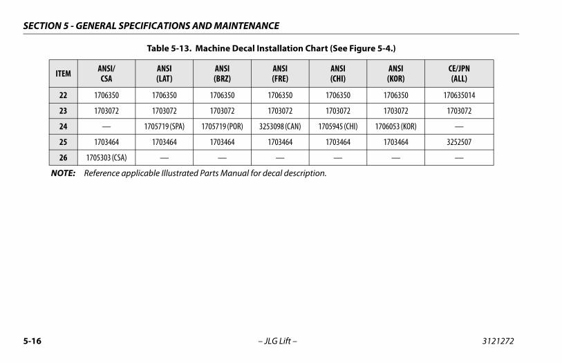
SECTION 5 - GENERAL SPECIFICATIONS AND MAINTENANCE
22 1706350 1706350 1706350 1706350 1706350 1706350 170635014
23 1703072 1703072 1703072 1703072 1703072 1703072 1703072
24 — 1705719 (SPA) 1705719 (POR) 3253098 (CAN) 1705945 (CHI) 1706053 (KOR) —
25 1703464 1703464 1703464 1703464 1703464 1703464 3252507
26 1705303 (CSA) — — — — — —
NOTE: Reference applicable Illustrated Parts Manual for decal description.
Table 5-13. Machine Decal Installation Chart (See Figure 5-4.)
ITEM ANSI/CSA
ANSI(LAT)
ANSI(BRZ)
ANSI(FRE)
ANSI(CHI)
ANSI(KOR)
CE/JPN(ALL)
5-16 – JLG Lift – 3121272
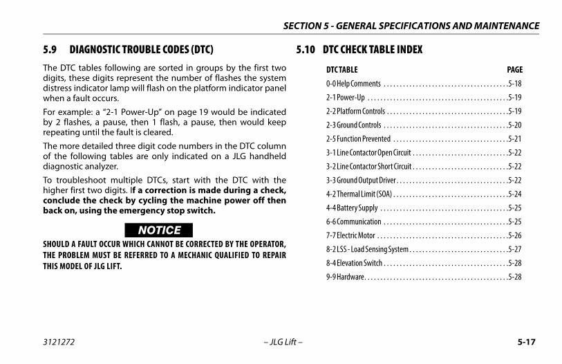
SECTION 5 - GENERAL SPECIFICATIONS AND MAINTENANCE
5.9 DIAGNOSTIC TROUBLE CODES (DTC)The DTC tables following are sorted in groups by the first twodigits, these digits represent the number of flashes the systemdistress indicator lamp will flash on the platform indicator panelwhen a fault occurs.
For example: a “2-1 Power-Up” on page 19 would be indicatedby 2 flashes, a pause, then 1 flash, a pause, then would keeprepeating until the fault is cleared.
The more detailed three digit code numbers in the DTC columnof the following tables are only indicated on a JLG handhelddiagnostic analyzer.
To troubleshoot multiple DTCs, start with the DTC with thehigher first two digits. If a correction is made during a check,conclude the check by cycling the machine power off thenback on, using the emergency stop switch.
NOTICESHOULD A FAULT OCCUR WHICH CANNOT BE CORRECTED BY THE OPERATOR,THE PROBLEM MUST BE REFERRED TO A MECHANIC QUALIFIED TO REPAIRTHIS MODEL OF JLG LIFT.
5.10 DTC CHECK TABLE INDEX
DTC TABLE PAGE0-0 Help Comments . . . . . . . . . . . . . . . . . . . . . . . . . . . . . . . . . . . . . . .5-18
2-1 Power-Up . . . . . . . . . . . . . . . . . . . . . . . . . . . . . . . . . . . . . . . . . . . .5-19
2-2 Platform Controls . . . . . . . . . . . . . . . . . . . . . . . . . . . . . . . . . . . . . .5-19
2-3 Ground Controls . . . . . . . . . . . . . . . . . . . . . . . . . . . . . . . . . . . . . . .5-20
2-5 Function Prevented . . . . . . . . . . . . . . . . . . . . . . . . . . . . . . . . . . . .5-21
3-1 Line Contactor Open Circuit . . . . . . . . . . . . . . . . . . . . . . . . . . . . . .5-22
3-2 Line Contactor Short Circuit . . . . . . . . . . . . . . . . . . . . . . . . . . . . . .5-22
3-3 Ground Output Driver . . . . . . . . . . . . . . . . . . . . . . . . . . . . . . . . . . .5-22
4-2 Thermal Limit (SOA) . . . . . . . . . . . . . . . . . . . . . . . . . . . . . . . . . . . .5-24
4-4 Battery Supply . . . . . . . . . . . . . . . . . . . . . . . . . . . . . . . . . . . . . . . .5-25
6-6 Communication . . . . . . . . . . . . . . . . . . . . . . . . . . . . . . . . . . . . . . .5-25
7-7 Electric Motor . . . . . . . . . . . . . . . . . . . . . . . . . . . . . . . . . . . . . . . . .5-26
8-2 LSS - Load Sensing System . . . . . . . . . . . . . . . . . . . . . . . . . . . . . . .5-27
8-4 Elevation Switch . . . . . . . . . . . . . . . . . . . . . . . . . . . . . . . . . . . . . . .5-28
9-9 Hardware. . . . . . . . . . . . . . . . . . . . . . . . . . . . . . . . . . . . . . . . . . . . .5-28
3121272 – JLG Lift – 5-17
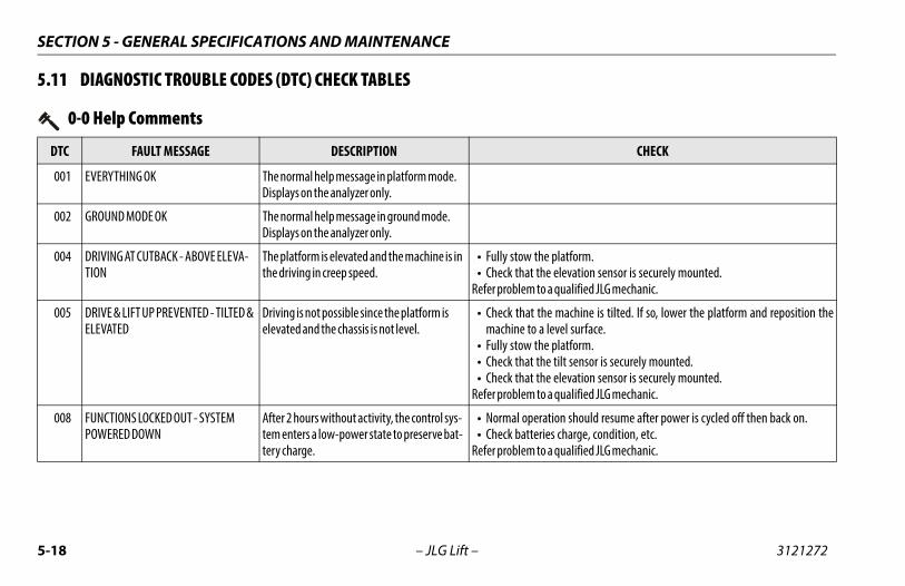
SECTION 5 - GENERAL SPECIFICATIONS AND MAINTENANCE
5.11 DIAGNOSTIC TROUBLE CODES (DTC) CHECK TABLES
0-0 Help Comments
DTC FAULT MESSAGE DESCRIPTION CHECK
001 EVERYTHING OK The normal help message in platform mode. Displays on the analyzer only.
002 GROUND MODE OK The normal help message in ground mode. Displays on the analyzer only.
004 DRIVING AT CUTBACK - ABOVE ELEVA-TION
The platform is elevated and the machine is in the driving in creep speed.
• Fully stow the platform.• Check that the elevation sensor is securely mounted.
Refer problem to a qualified JLG mechanic.
005 DRIVE & LIFT UP PREVENTED - TILTED & ELEVATED
Driving is not possible since the platform is elevated and the chassis is not level.
• Check that the machine is tilted. If so, lower the platform and reposition themachine to a level surface.
• Fully stow the platform.• Check that the tilt sensor is securely mounted.• Check that the elevation sensor is securely mounted.
Refer problem to a qualified JLG mechanic.
008 FUNCTIONS LOCKED OUT - SYSTEM POWERED DOWN
After 2 hours without activity, the control sys-tem enters a low-power state to preserve bat-tery charge.
• Normal operation should resume after power is cycled off then back on.• Check batteries charge, condition, etc.
Refer problem to a qualified JLG mechanic.
5-18 – JLG Lift – 3121272
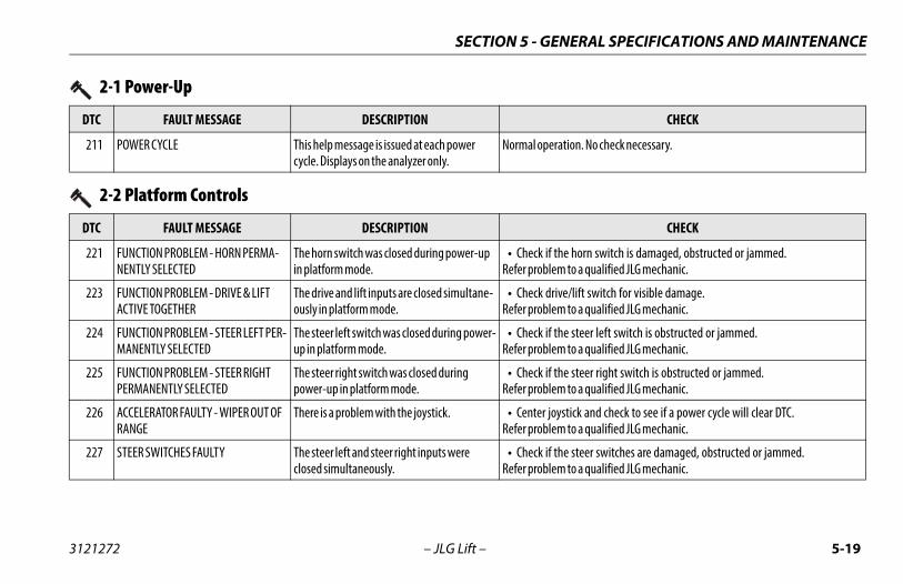
SECTION 5 - GENERAL SPECIFICATIONS AND MAINTENANCE
2-1 Power-Up
DTC FAULT MESSAGE DESCRIPTION CHECK
211 POWER CYCLE This help message is issued at each power cycle. Displays on the analyzer only.
Normal operation. No check necessary.
2-2 Platform Controls
DTC FAULT MESSAGE DESCRIPTION CHECK
221 FUNCTION PROBLEM - HORN PERMA-NENTLY SELECTED
The horn switch was closed during power-up in platform mode.
• Check if the horn switch is damaged, obstructed or jammed.Refer problem to a qualified JLG mechanic.
223 FUNCTION PROBLEM - DRIVE & LIFT ACTIVE TOGETHER
The drive and lift inputs are closed simultane-ously in platform mode.
• Check drive/lift switch for visible damage.Refer problem to a qualified JLG mechanic.
224 FUNCTION PROBLEM - STEER LEFT PER-MANENTLY SELECTED
The steer left switch was closed during power-up in platform mode.
• Check if the steer left switch is obstructed or jammed.Refer problem to a qualified JLG mechanic.
225 FUNCTION PROBLEM - STEER RIGHT PERMANENTLY SELECTED
The steer right switch was closed during power-up in platform mode.
• Check if the steer right switch is obstructed or jammed.Refer problem to a qualified JLG mechanic.
226 ACCELERATOR FAULTY - WIPER OUT OF RANGE
There is a problem with the joystick. • Center joystick and check to see if a power cycle will clear DTC.Refer problem to a qualified JLG mechanic.
227 STEER SWITCHES FAULTY The steer left and steer right inputs were closed simultaneously.
• Check if the steer switches are damaged, obstructed or jammed.Refer problem to a qualified JLG mechanic.
3121272 – JLG Lift – 5-19
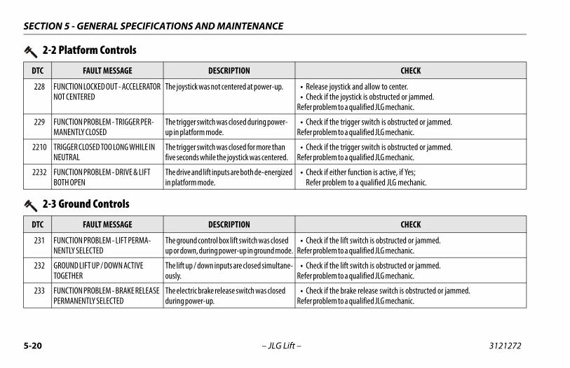
SECTION 5 - GENERAL SPECIFICATIONS AND MAINTENANCE
228 FUNCTION LOCKED OUT - ACCELERATOR NOT CENTERED
The joystick was not centered at power-up. • Release joystick and allow to center.• Check if the joystick is obstructed or jammed.
Refer problem to a qualified JLG mechanic.
229 FUNCTION PROBLEM - TRIGGER PER-MANENTLY CLOSED
The trigger switch was closed during power-up in platform mode.
• Check if the trigger switch is obstructed or jammed.Refer problem to a qualified JLG mechanic.
2210 TRIGGER CLOSED TOO LONG WHILE IN NEUTRAL
The trigger switch was closed for more than five seconds while the joystick was centered.
• Check if the trigger switch is obstructed or jammed.Refer problem to a qualified JLG mechanic.
2232 FUNCTION PROBLEM - DRIVE & LIFT BOTH OPEN
The drive and lift inputs are both de-energized in platform mode.
• Check if either function is active, if Yes;Refer problem to a qualified JLG mechanic.
2-2 Platform Controls
DTC FAULT MESSAGE DESCRIPTION CHECK
2-3 Ground Controls
DTC FAULT MESSAGE DESCRIPTION CHECK
231 FUNCTION PROBLEM - LIFT PERMA-NENTLY SELECTED
The ground control box lift switch was closed up or down, during power-up in ground mode.
• Check if the lift switch is obstructed or jammed.Refer problem to a qualified JLG mechanic.
232 GROUND LIFT UP / DOWN ACTIVE TOGETHER
The lift up / down inputs are closed simultane-ously.
• Check if the lift switch is obstructed or jammed.Refer problem to a qualified JLG mechanic.
233 FUNCTION PROBLEM - BRAKE RELEASE PERMANENTLY SELECTED
The electric brake release switch was closed during power-up.
• Check if the brake release switch is obstructed or jammed.Refer problem to a qualified JLG mechanic.
5-20 – JLG Lift – 3121272
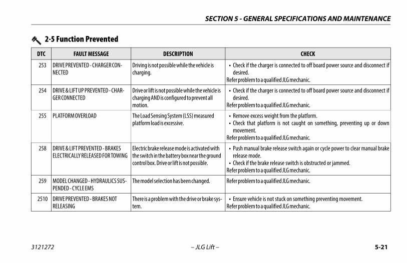
SECTION 5 - GENERAL SPECIFICATIONS AND MAINTENANCE
2-5 Function Prevented
DTC FAULT MESSAGE DESCRIPTION CHECK
253 DRIVE PREVENTED - CHARGER CON-NECTED
Driving is not possible while the vehicle is charging.
• Check if the charger is connected to off board power source and disconnect ifdesired.
Refer problem to a qualified JLG mechanic.
254 DRIVE & LIFT UP PREVENTED - CHAR-GER CONNECTED
Drive or lift is not possible while the vehicle is charging AND is configured to prevent all motion.
• Check if the charger is connected to off board power source and disconnect ifdesired.
Refer problem to a qualified JLG mechanic.
255 PLATFORM OVERLOAD The Load Sensing System (LSS) measured platform load is excessive.
• Remove excess weight from the platform.• Check that platform is not caught on something, preventing up or down
movement.Refer problem to a qualified JLG mechanic.
258 DRIVE & LIFT PREVENTED - BRAKES ELECTRICALLY RELEASED FOR TOWING
Electric brake release mode is activated with the switch in the battery box near the ground control box. Drive or lift is not possible.
• Push manual brake release switch again or cycle power to clear manual brakerelease mode.
• Check if the brake release switch is obstructed or jammed.Refer problem to a qualified JLG mechanic.
259 MODEL CHANGED - HYDRAULICS SUS-PENDED - CYCLE EMS
The model selection has been changed. Refer problem to a qualified JLG mechanic.
2510 DRIVE PREVENTED - BRAKES NOT RELEASING
There is a problem with the drive or brake sys-tem.
• Ensure vehicle is not stuck on something preventing movement.Refer problem to a qualified JLG mechanic.
3121272 – JLG Lift – 5-21
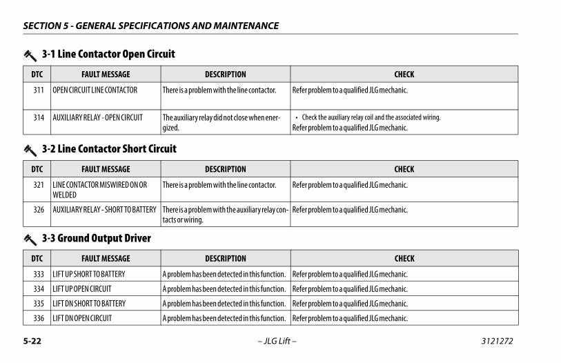
SECTION 5 - GENERAL SPECIFICATIONS AND MAINTENANCE
3-1 Line Contactor Open Circuit
DTC FAULT MESSAGE DESCRIPTION CHECK
311 OPEN CIRCUIT LINE CONTACTOR There is a problem with the line contactor. Refer problem to a qualified JLG mechanic.
314 AUXILIARY RELAY - OPEN CIRCUIT The auxiliary relay did not close when ener-gized.
• Check the auxiliary relay coil and the associated wiring.Refer problem to a qualified JLG mechanic.
3-2 Line Contactor Short Circuit
DTC FAULT MESSAGE DESCRIPTION CHECK
321 LINE CONTACTOR MISWIRED ON OR WELDED
There is a problem with the line contactor. Refer problem to a qualified JLG mechanic.
326 AUXILIARY RELAY - SHORT TO BATTERY There is a problem with the auxiliary relay con-tacts or wiring.
Refer problem to a qualified JLG mechanic.
3-3 Ground Output Driver
DTC FAULT MESSAGE DESCRIPTION CHECK
333 LIFT UP SHORT TO BATTERY A problem has been detected in this function. Refer problem to a qualified JLG mechanic.
334 LIFT UP OPEN CIRCUIT A problem has been detected in this function. Refer problem to a qualified JLG mechanic.
335 LIFT DN SHORT TO BATTERY A problem has been detected in this function. Refer problem to a qualified JLG mechanic.
336 LIFT DN OPEN CIRCUIT A problem has been detected in this function. Refer problem to a qualified JLG mechanic.
5-22 – JLG Lift – 3121272
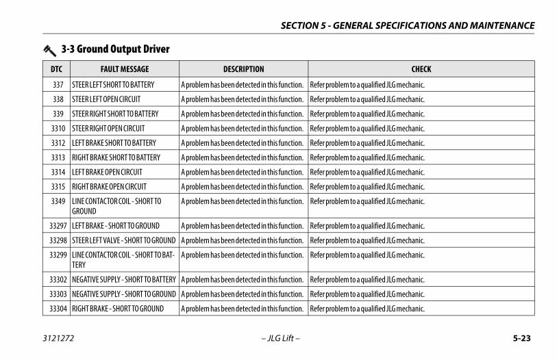
SECTION 5 - GENERAL SPECIFICATIONS AND MAINTENANCE
337 STEER LEFT SHORT TO BATTERY A problem has been detected in this function. Refer problem to a qualified JLG mechanic.
338 STEER LEFT OPEN CIRCUIT A problem has been detected in this function. Refer problem to a qualified JLG mechanic.
339 STEER RIGHT SHORT TO BATTERY A problem has been detected in this function. Refer problem to a qualified JLG mechanic.
3310 STEER RIGHT OPEN CIRCUIT A problem has been detected in this function. Refer problem to a qualified JLG mechanic.
3312 LEFT BRAKE SHORT TO BATTERY A problem has been detected in this function. Refer problem to a qualified JLG mechanic.
3313 RIGHT BRAKE SHORT TO BATTERY A problem has been detected in this function. Refer problem to a qualified JLG mechanic.
3314 LEFT BRAKE OPEN CIRCUIT A problem has been detected in this function. Refer problem to a qualified JLG mechanic.
3315 RIGHT BRAKE OPEN CIRCUIT A problem has been detected in this function. Refer problem to a qualified JLG mechanic.
3349 LINE CONTACTOR COIL - SHORT TO GROUND
A problem has been detected in this function. Refer problem to a qualified JLG mechanic.
33297 LEFT BRAKE - SHORT TO GROUND A problem has been detected in this function. Refer problem to a qualified JLG mechanic.
33298 STEER LEFT VALVE - SHORT TO GROUND A problem has been detected in this function. Refer problem to a qualified JLG mechanic.
33299 LINE CONTACTOR COIL - SHORT TO BAT-TERY
A problem has been detected in this function. Refer problem to a qualified JLG mechanic.
33302 NEGATIVE SUPPLY - SHORT TO BATTERY A problem has been detected in this function. Refer problem to a qualified JLG mechanic.
33303 NEGATIVE SUPPLY - SHORT TO GROUND A problem has been detected in this function. Refer problem to a qualified JLG mechanic.
33304 RIGHT BRAKE - SHORT TO GROUND A problem has been detected in this function. Refer problem to a qualified JLG mechanic.
3-3 Ground Output Driver
DTC FAULT MESSAGE DESCRIPTION CHECK
3121272 – JLG Lift – 5-23
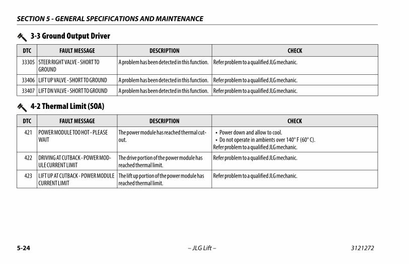
SECTION 5 - GENERAL SPECIFICATIONS AND MAINTENANCE
33305 STEER RIGHT VALVE - SHORT TO GROUND
A problem has been detected in this function. Refer problem to a qualified JLG mechanic.
33406 LIFT UP VALVE - SHORT TO GROUND A problem has been detected in this function. Refer problem to a qualified JLG mechanic.
33407 LIFT DN VALVE - SHORT TO GROUND A problem has been detected in this function. Refer problem to a qualified JLG mechanic.
3-3 Ground Output Driver
DTC FAULT MESSAGE DESCRIPTION CHECK
4-2 Thermal Limit (SOA)
DTC FAULT MESSAGE DESCRIPTION CHECK
421 POWER MODULE TOO HOT - PLEASE WAIT
The power module has reached thermal cut-out.
• Power down and allow to cool.• Do not operate in ambients over 140° F (60° C).
Refer problem to a qualified JLG mechanic.
422 DRIVING AT CUTBACK - POWER MOD-ULE CURRENT LIMIT
The drive portion of the power module has reached thermal limit.
Refer problem to a qualified JLG mechanic.
423 LIFT UP AT CUTBACK - POWER MODULE CURRENT LIMIT
The lift up portion of the power module has reached thermal limit.
Refer problem to a qualified JLG mechanic.
5-24 – JLG Lift – 3121272
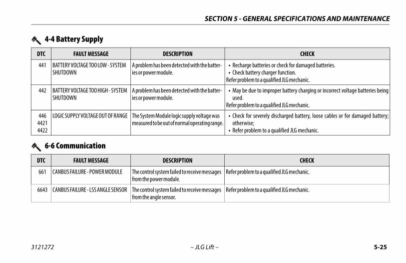
SECTION 5 - GENERAL SPECIFICATIONS AND MAINTENANCE
4-4 Battery Supply
DTC FAULT MESSAGE DESCRIPTION CHECK
441 BATTERY VOLTAGE TOO LOW - SYSTEM SHUTDOWN
A problem has been detected with the batter-ies or power module.
• Recharge batteries or check for damaged batteries.• Check battery charger function.
Refer problem to a qualified JLG mechanic.
442 BATTERY VOLTAGE TOO HIGH - SYSTEM SHUTDOWN
A problem has been detected with the batter-ies or power module.
• May be due to improper battery charging or incorrect voltage batteries beingused.
Refer problem to a qualified JLG mechanic.
44644214422
LOGIC SUPPLY VOLTAGE OUT OF RANGE The System Module logic supply voltage was measured to be out of normal operating range.
• Check for severely discharged battery, loose cables or for damaged battery;otherwise;
• Refer problem to a qualified JLG mechanic.
6-6 Communication
DTC FAULT MESSAGE DESCRIPTION CHECK
661 CANBUS FAILURE - POWER MODULE The control system failed to receive messages from the power module.
Refer problem to a qualified JLG mechanic.
6643 CANBUS FAILURE - LSS ANGLE SENSOR The control system failed to receive messages from the angle sensor.
Refer problem to a qualified JLG mechanic.
3121272 – JLG Lift – 5-25
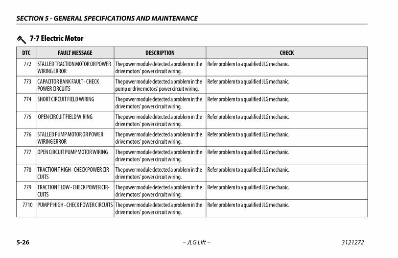
SECTION 5 - GENERAL SPECIFICATIONS AND MAINTENANCE
7-7 Electric Motor
DTC FAULT MESSAGE DESCRIPTION CHECK
772 STALLED TRACTION MOTOR OR POWER WIRING ERROR
The power module detected a problem in the drive motors' power circuit wiring.
Refer problem to a qualified JLG mechanic.
773 CAPACITOR BANK FAULT - CHECK POWER CIRCUITS
The power module detected a problem in the pump or drive motors' power circuit wiring.
Refer problem to a qualified JLG mechanic.
774 SHORT CIRCUIT FIELD WIRING The power module detected a problem in the drive motors' power circuit wiring.
Refer problem to a qualified JLG mechanic.
775 OPEN CIRCUIT FIELD WIRING The power module detected a problem in the drive motors' power circuit wiring.
Refer problem to a qualified JLG mechanic.
776 STALLED PUMP MOTOR OR POWER WIRING ERROR
The power module detected a problem in the drive motors' power circuit wiring.
Refer problem to a qualified JLG mechanic.
777 OPEN CIRCUIT PUMP MOTOR WIRING The power module detected a problem in the drive motors' power circuit wiring.
Refer problem to a qualified JLG mechanic.
778 TRACTION T HIGH - CHECK POWER CIR-CUITS
The power module detected a problem in the drive motors' power circuit wiring.
Refer problem to a qualified JLG mechanic.
779 TRACTION T LOW - CHECK POWER CIR-CUITS
The power module detected a problem in the drive motors' power circuit wiring.
Refer problem to a qualified JLG mechanic.
7710 PUMP P HIGH - CHECK POWER CIRCUITS The power module detected a problem in the drive motors' power circuit wiring.
Refer problem to a qualified JLG mechanic.
5-26 – JLG Lift – 3121272
SECTION 5 - GENERAL SPECIFICATIONS AND MAINTENANCE
7711 PUMP P LOW - CHECK POWER CIRCUITS The power module detected a problem in the drive motors' power circuit wiring.
Refer problem to a qualified JLG mechanic.
7741 ARMATURE BRAKING CURRENT TOO HIGH
The power module has detected excessive braking current.
This can be caused by transporting an excessive load on a steep grade.
7742 FIELD VOLTAGE IMPROPER The power module detected a problem in the drive motors' power circuit wiring.
Recycle power on/off, if problem persists;Refer problem to a qualified JLG mechanic.
7-7 Electric Motor
DTC FAULT MESSAGE DESCRIPTION CHECK
8-2 LSS - Load Sensing System
DTC FAULT MESSAGE DESCRIPTION CHECK
8212 LSS PRESSURE SENSOR -DISAGREEMENT
Pressure Sensor 1 and Pressure Sensor 2 do not agree. The system shall assume the machine is overloaded until the sensors agree.
Refer problem to a qualified JLG mechanic.
8213 LSS ANGLE SENSOR -DISAGREEMENT
The angle sensor’s change in reading does not agree with the direction of themachine motion (lift up).
Refer problem to a qualified JLG mechanic.
8214 LSS ANGLE SENSOR -DIRECTION DISAGREEMENT
The angle sensor’s reading when the machine is at maximum elevation does not fall within the high end acceptable range.
Refer problem to a qualified JLG mechanic.
3121272 – JLG Lift – 5-27
SECTION 5 - GENERAL SPECIFICATIONS AND MAINTENANCE
8215 LSS ANGLE SENSOR -OUT OF RANGE LOW
The angle sensor’s reading when the machine is stowed does not fall within the low end acceptable range.
Refer problem to a qualified JLG mechanic.
8216 LSS ANGLE SENSOR HAS NOT BEEN CAL-IBRATED
The Angle Sensor has never been calibrated and the control system assumes that the plat-form is overloaded.
Refer problem to a qualified JLG mechanic.
8-2 LSS - Load Sensing System
DTC FAULT MESSAGE DESCRIPTION CHECK
8-4 Elevation Switch
DTC FAULT MESSAGE DESCRIPTION CHECK
84109 ELEVATION SWITCH CONTACTS DIS-AGREEMENT
The elevation switch is repeating an incorrect value.
Refer problem to a qualified JLG mechanic.
9-9 Hardware
DTC FAULT MESSAGE DESCRIPTION CHECK
995 POWER MODULE FAILURE - PERSONAL-ITY RANGE ERROR
A problem has been detected with the power module.
Refer problem to a qualified JLG mechanic.
996 POWER MODULE FAILURE - INTERNAL ERROR
A problem has been detected with the power module.
Refer problem to a qualified JLG mechanic.
5-28 – JLG Lift – 3121272
SECTION 5 - GENERAL SPECIFICATIONS AND MAINTENANCE
998 EEPROM FAILURE - CHECK ALL SET-TINGS
The control system detected an EEPROM fail-ure.
Refer problem to a qualified JLG mechanic.
999 FUNCTION LOCKED OUT - POWER MOD-ULE SOFTWARE VERSION IMPROPER
The power module software version is not compatible with the rest of the system.
Refer problem to a qualified JLG mechanic.
9-9 Hardware
DTC FAULT MESSAGE DESCRIPTION CHECK
3121272 – JLG Lift – 5-29
SECTION 5 - GENERAL SPECIFICATIONS AND MAINTENANCE
9950995199529953995499559956995799589960996299639964996999709971
99143991449914599146991479914899149
POWER MODULE FAILURE - INTERNAL ERROR
A problem has been detected with the power module.
Cycle machine power on /off a few times if this doesn’t clear the DTC,refer problem to a qualified JLG mechanic.
9-9 Hardware
DTC FAULT MESSAGE DESCRIPTION CHECK
5-30 – JLG Lift – 3121272
SECTION 6 - INSPECTION AND REPAIR LOG
SECTION 6. INSPECTION AND REPAIR LOGMachine Serial Number _______________________________________
Table 6-1. Inspection and Repair Log
DATE COMMENTS
3121272 – JLG Lift – 6-1
SECTION 6 - INSPECTION AND REPAIR LOG
Table 6-1. Inspection and Repair Log
DATE COMMENTS
6-2 – JLG Lift – 3121272

Corporate OfficeJLG Industries, Inc.
1 JLG DriveMcConnellsburg, PA 17233-9533 USA
(717) 485-5161 (Corporate) (877) 554-5438 (Customer Support)
(717) 485-6417
Visit our website for JLG Worldwide Locations. www.jlg.com