Embed Size (px)
Citation preview
Operation And SafetyManual
Original Instructions
Keep this manual with machine at all times.
ADJUSTABLEPERFORMANCE
COUNTERWEIGHT
5376000182
March 1, 2017
SUPPLEMENTAL MANUAL

Revision Log
5376000182 a
REVISION LOGMarch 1, 2017 - 0 - Original Issue of Manual. CN 164269
Read This First
b 5376000182
This manual provides supplemental Operational and Safety information for the Ad-justable Performance Counterweight. Read this manual and the Operation and Safety Manual provided with other equipment thoroughly prior to starting operation.
This manual is a very important tool! Keep it with the machine at all times.
The purpose of this manual is to provide owners, users, and operators with the precautions and operating procedures essential for the safe and proper machine operation for its intended purpose.
Due to continuous product improvements, Jerr-Dan Corporation reserves the right to make specifi cation changes without prior notifi cation. Contact Jerr-Dan Corporation for updated information.
OPERATOR QUALIFICATIONS
The operator of the machine must not operate the machine until this manual has been read, training is accomplished and operation of the machine has been completed under the supervision of an experienced and qualifi ed operator.
Operators of this equipment must possess a valid, applicable driver’s license, be in good physical and mental condition, have normal refl exes and reaction time, good vision and depth perception and normal hearing. Operator must not be using medication which could impair abilities nor be under the infl uence of alcohol or any other intoxicant during the work shift.
In addition, the operator must read, understand and comply with instructions contained in the following material furnished with the equipment:
• This Operation & Safety Manual
• All instructional decals and plates
• Any optional equipment instructions furnished
• Commercial vehicle’s Operation & Maintenance Manuals
The operator must also read, understand and comply with all applicable Employer, Industry and Governmental rules, standards and regulations.
MODIFICATIONS
Any modifi cation to this machine must be approved by Jerr-Dan.
Read This First
5376000182 c
HAZARD CLASSIFICATION SYSTEM
SAFETY ALERT SYSTEM AND SAFETY SIGNAL WORDS
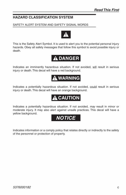
This is the Safety Alert Symbol. It is used to alert you to the potential personal injury hazards. Obey all safety messages that follow this symbol to avoid possible injury or death.
Indicates an imminently hazardous situation. If not avoided, will result in serious injury or death. This decal will have a red background.
Indicates a potentially hazardous situation. If not avoided, could result in serious injury or death. This decal will have an orange background.
Indicates a potentially hazardous situation. If not avoided, may result in minor or moderate injury. It may also alert against unsafe practices. This decal will have a yellow background.
Indicates information or a comply policy that relates directly or indirectly to the safety of the personnel or protection of property.
Read This First
d 5376000182
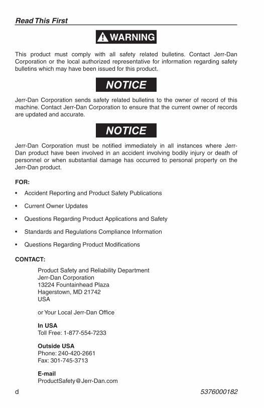
This product must comply with all safety related bulletins. Contact Jerr-Dan Corporation or the local authorized representative for information regarding safety bulletins which may have been issued for this product.
Jerr-Dan Corporation sends safety related bulletins to the owner of record of this machine. Contact Jerr-Dan Corporation to ensure that the current owner of records are updated and accurate.
Jerr-Dan Corporation must be notifi ed immediately in all instances where Jerr-Dan product have been involved in an accident involving bodily injury or death of personnel or when substantial damage has occurred to personal property on the Jerr-Dan product.
FOR:
• Accident Reporting and Product Safety Publications
• Current Owner Updates
• Questions Regarding Product Applications and Safety
• Standards and Regulations Compliance Information
• Questions Regarding Product Modifi cations
CONTACT:
Product Safety and Reliability DepartmentJerr-Dan Corporation13224 Fountainhead PlazaHagerstown, MD 21742USA
or Your Local Jerr-Dan Offi ce
In USAToll Free: 1-877-554-7233
Outside USAPhone: 240-420-2661Fax: 301-745-3713
Read This First
5376000182 e
REPORTING SAFETY DEFECTSIf you believe that your vehicle has a defect which could cause a crash or could cause injury or death, you should immediately inform the National Highway Traffi c Safety Administration (NHTSA) in addition to notifying Jerr-Dan Corporation.
If NHTSA receives similar complaints, it opens an investigation, and if it fi nds that a safety defect exists in a group of vehicles, it may order a recall and remedy campaign. However, NHTSA cannot become involved in individual problems between you, your dealer, or Jerr-Dan Corporation.
To contact NHTSA, you may call the Vehicle Safety Hotline toll-free at 1-888-327-4236 (TTY: 1-800-424-9153; go to http://www.safercar.gov; or write to:
Administrator NHTSA 400 Seventh Street S.W. Washington, DC 20590
You can also obtain other information about motor vehicle safety from http://www.safercar.gov.

THIS PAGE IS INTENTIONALLY LEFT BLANK
Table of Contents
5376000182 i
TABLE OF CONTENTS
Revision Log
Read This FirstOperator Qualifi cations .............................................................. bModifi cations .............................................................................. bHazard Classifi cation System .................................................... cSafety Alert System And Safety Signal Words ........................... cReporting Safety Defects ............................................................ e
Table of Contents
Section 1 - General Safety Practices1.1 General ...................................................................................... 1-11.2 Pre-operation ............................................................................. 1-2
Operator Training And Knowledge .......................................... 1-2Crush And Collision Hazards .................................................. .1-3Fall Hazards ............................................................................ 1-3Chemical Hazards .................................................................. 1-4Battery Hazards ...................................................................... 1-5Personal Protective Equipment ............................................... 1-5Weather Conditions ................................................................. .1-6Vehicle Equipment Damage ................................................... .1-6
Section 2 - Pre-operation And Inspection2.1 Pre-operation Check And Inspection ......................................... 2-12.2 Decals ........................................................................................ 2-22.3 Walk-around Inspection ............................................................... 2-32.4 Operational Checks ..................................................................... 2-5
Section 3 - Controls & Indicators3.1 General ...................................................................................... 3-13.2 Controls ...................................................................................... 3-2
Electrical Controls - Passanger Side ...................................... 3-2Manual Controls - Passanger Side ......................................... .3-2
Section 4 - Operation4.1 Counterweight Operation ........................................................... 4-14.2 Adding Aditional Weight .............................................................. 4-24.3 Removing Weight ........................................................................ 4-5
Section 5 - Manual Pump Operation5.1 Raising/Lowerering the Counterweight ....................................... 5-1
Table of Contents
ii 5376000182
Section 6 - Maintenance
Introduction ................................................................................ 6-16.1 Maintenance And Lubrication ..................................................... 6-26.2 Oils .............................................................................................. 6-26.3 Trouble Shooting ........................................................................ .6-3
Hydraulic System ................................................................... . 6-3Hydraulic Pump ..................................................................... . 6-4
Section 7 - Specifi cations7.1 Product Specifi cations ................................................................ 7-17.2 Capacities .................................................................................. 7-1
Inspection, Maintenance and Repair Log
Transfer of Ownership
Section I - General Safety Practices
5376000182 1-1
SECTION 1 - GENERAL SAFETY PRACTICES
1.1 GENERALThis section outlines the necessary precautions for proper and safe machine operation and maintenance. For proper machine use, it is mandatory that a daily routine is established based on the content of this manual. A maintenance program, using the information provided in this manual must also be established by a qualifi ed person and followed to ensure the machine is safe to operate.
The owner/user/operator of the machine must not operate the machine until this manual has been read, training is accomplished, and operation of the machine has been completed under the supervision of an experienced and qualifi ed operator.
There may be times your truck my be exposed to direct contact with the public such as parades, charitable fundraisers, etc. Before allowing anyone other than a trained and experienced employee of your company near your truck, you should consult with your company safety offi cer and plan for safety.
If there are any question with regard to safety, training, inspection, maintenance, application, and operation, please contact Jerr-Dan Corporation.
Failure to comply with the safety precautions listed in this manual could result in machine damage, property damage, personal injury or death.
�������
Section I - General Safety Practices
1-2 5376000182
1.2 PRE-OPERATION
OPERATOR TRAINING AND KNOWLEDGE
• Read and understand this manual before operating the machine.
• Do not operate this machine until complete training is performed by authorized persons.
• Only authorized and qualifi ed personnel can operate the machine.
• Read, understand, and obey all DANGERS, WARNINGS, CAUTIONS, and operating instructions on the machine and in the manual.
• Use the machine in a manner which is within the scope of its intended application set by Jerr-Dan.
• All operating personnel must be familiar with the emergency operation of the machine as specifi ed in this manual.
• Read, understand, and obey all applicable employer, local, and government regulations as the pertain to the operation of the machine.
Section I - General Safety Practices
5376000182 1-3
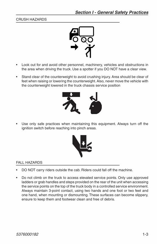
CRUSH HAZARDS
• Look out for and avoid other personnel, machinery, vehicles and obstructions in the area when driving the truck. Use a spotter if you DO NOT have a clear view.
• Stand clear of the counterweight to avoid crushing injury. Area should be clear of feet when raising or lowering the counterweight. Also, never move the vehicle with the counterweight lowered in the truck chassis service position
• Use only safe practices when maintaining this equipment. Always turn off the ignition switch before reaching into pinch areas.
FALL HAZARDS
• DO NOT carry riders outside the cab. Riders could fall off the machine.
• Do not climb on the truck to access elevated service points. Only use approved ladders or grab handles and steps provided on the rear of the unit when accessing the service points on the top of the truck body in a controlled service environment. Always maintain 3-point contact, using two hands and one foot or two feet and one hand, when mounting or dismounting. These surfaces can become slippery, ensure to keep them and footwear clean and free of debris.
Section I - General Safety Practices
1-4 5376000182
CHEMICAL HAZARDS
Exhaust Fumes
• DO NOT operate machine in an enclosed area without proper ventilation.
• DO NOT operate the machine in hazardous environments unless approved for that purpose by Jerr-Dan and site owner. Sparks from the electrical system and the engine exhaust can cause an explosion.
Flammable Fuel
• DO NOT attempt to repair or tighten any hydraulic hoses or fi ttings while the engine is running or when the hydraulic system is under pressure.
Hydraulic Fluid
• Stop engine and relieve trapped pressure. Fluid in the hydraulic system is under pressure and can penetrate the skin.
• DO NOT use your hand to check for leaks. Use a piece of cardboard or paper to search for leaks. Wear gloves to protect hands from spraying fl uid.
Section I - General Safety Practices
5376000182 1-5
BATTERY HAZARDS
• Battery fl uid is highly corrosive. Avoid contact with skin and clothing at all times.
• Keep sparks, fl ames, and lighted materials away from batteries.
• Charge batteries only in a well ventilated area.
• Wear proper eye protection when servicing battery.
PERSONAL PROTECTIVE EQUIPMENT
• Use personal protective equipment when working on or around this vehicle.
• Remove rings, watches, jewellery, neckwear or other items that can catch in equipment.
• Wear : o Snug fi tting and sturdy long-sleeve shirt and long pants. Avoid loose fi tting
clothes.
o Sturdy gloves.
o Approved eye protection.
o Steel toed boots.
o Approved head gear.
o Approved hearing protection.
Section I - General Safety Practices
1-6 5376000182
WEATHER CONDITIONS
• If using in freezing conditions, you must be alert to possibility of ice forming on the device. Use Caution when raising and lowering the counterweight.
• Hydraulic cylinders are subject to thermal expansion and contraction. This may result in changes to the counterweight position while the machine is stationary. Factors affecting thermal movement can include the length of time the machine is stationary, hydraulic oil temperature, and ambient air temperature.
VEHICLE EQUIPMENT DAMAGE
• Do not move the vehicle while rear counterweight is lowered.
• Do not use machine as a ground when performing any welding operations.
Section II : Pre-operation and Inspection
5376000182 2-1
SECTION 2 - PRE OPERATION AND INSPECTION
2.1 PRE-OPERATION CHECK AND INSPECTIONNote: Complete all required maintenance before operating unit.
FALL HAZARD. Use extreme caution when checking items beyond your normal reach. Use an approved ladder.
�������
The pre-operation check and inspection, performed at beginning of each work shift or at each change of operator, should include the following:
1. Cleanliness - Check all surfaces for leakage (oil, fuel or battery fl uid) or foreign objects. Report any leakage to the proper maintenance personnel.
2. Structure - Inspect the machine structure for dents, damage, weld or parent metal cracks or other discrepancies.
3. Safety Decals Placards - Ensure all decals are legible and in place. Clean or replace as required. See page 2-2 for details.
4. Operation and Safety Manual(s) - Operation & Safety Manual(s) are in cab.
5. Walk-Around Inspection - See page 2-3 for details.
6. Attachments - Inspect attachments for dents, damage, weld or parent metal cracks or other discrepancies.
7. Operational Check - Once the walk-around inspection is complete, perform an operational check (see page 2-5) of all systems in an area free of ground level obstructions. See Section 3 - Controls and Indicators for more specifi c operating instructions.
If your counterweight does not operate properly, immediately bring machine to a stop, lower boom to stowed position and stop the engine. Determine cause and correct before continued use.
�������
Section II : Pre-operation and Inspection
2-2 5376000182
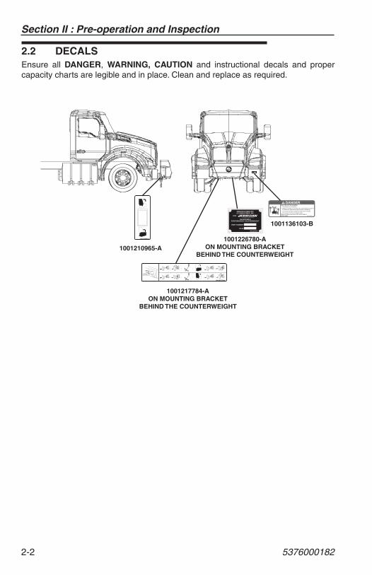
2.2 DECALSEnsure all DANGER, WARNING, CAUTION and instructional decals and proper capacity charts are legible and in place. Clean and replace as required.
1001210965-A
PART NUMBER
DATE
MANUFACTURED BY:JLG INDUSTRIES, INC.
1001226780-A
FOR:
ADJUSTABLEPERFORMANCE COUNTERWEIGHT
1001217784-A
1001210965-A
1001217784-AON MOUNTING BRACKET
BEHIND THE COUNTERWEIGHT
1001226780-AON MOUNTING BRACKET
BEHIND THE COUNTERWEIGHT
1001136103-B
1001136103-B
DANGER
Section II : Pre-operation and Inspection
5376000182 2-3
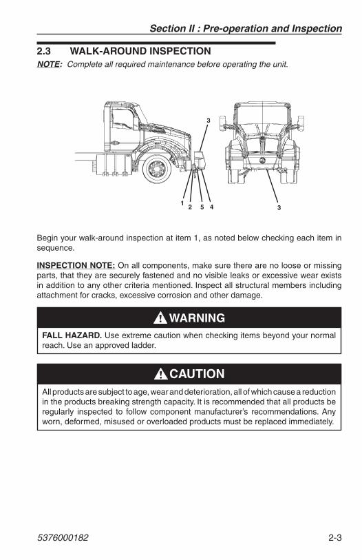
2.3 WALK-AROUND INSPECTIONNOTE: Complete all required maintenance before operating the unit.
31
2
3
45
Begin your walk-around inspection at item 1, as noted below checking each item in sequence.
INSPECTION NOTE: On all components, make sure there are no loose or missing parts, that they are securely fastened and no visible leaks or excessive wear exists in addition to any other criteria mentioned. Inspect all structural members including attachment for cracks, excessive corrosion and other damage.
FALL HAZARD. Use extreme caution when checking items beyond your normal reach. Use an approved ladder.
�������
All products are subject to age, wear and deterioration, all of which cause a reduction in the products breaking strength capacity. It is recommended that all products be regularly inspected to follow component manufacturer’s recommendations. Any worn, deformed, misused or overloaded products must be replaced immediately.
�����
Section II : Pre-operation and Inspection
2-4 5376000182
1. Counterweight Adapter Pins – Left Hand and Right Hand
a. Check attachment points to front of chassis frame
b. Components undamaged
c. Check attachment to front of chassis frame, Bolts, secure
d. Check attachment to front of chassis frame, Nuts, secure
2. Counterweight Adapter Plate – Left Hand and Right Hand
a. Check attachment to front of adapter pins, Bolts, secure
b. Components undamaged
3. Counterweight
a. Components undamaged
b. Pivot Pins, secure
4. Hydraulic Cylinder
a. Components undamaged
b. Pins, secure
c. Hydraulic hoses undamaged, not leaking
5. Hydraulic Power Unit
a. Components undamaged
b. Hydraulic fl uid level full
c. Valve not leaking
Section II : Pre-operation and Inspection
5376000182 2-5
2.4 OPERATIONAL CHECKS
OPERATIONAL CHECK
1. Electric over hydraulic controlled functions - all functions operate smoothly and the switch returns to the “Neutral Off” position.
2. Manually controlled hydraulic functions - all functions operate smoothly.
Stand clear of the counterweight to avoid crushing injury. Area should be clear of feet when raising or lowering the counterweight. Also, never move the vehicle with the counterweight lowered in the truck chassis service position.
�����

THIS PAGE IS INTENTIONALLY LEFT BLANK
Section II : Pre-operation and Inspection
2-6 5376000182
Section III - Controls & Indicators
5376000182 3-1
SECTION 3 - CONTROLS & INDICATORS
3.1 GENERALThis section provides the necessary information needed to understand control functions.
The counterweight is supplied with two methods of operation.
The toggle switch in the counterweight adapter plate controls the hydraulic power unit of the counterweight to control the tilt up and tilt down functions.
There is also a manual pump that allows the user to provide hydraulic power to the cylinder should the electrical system fail to operate.
Note: The manufacturer has no direct control over machine application and operation. The user and operator are responsible for conforming with good safety practices.
Section III - Controls & Indicators
3-2 5376000182
3.2 CONTROLS
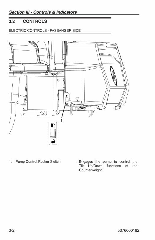
ELECTRIC CONTROLS - PASSANGER SIDE
1001210965-A
1
1001210965-A
1. Pump Control Rocker Switch : Engages the pump to control the Tilt Up/Down functions of the Counterweight.
Section III - Controls & Indicators
5376000182 3-3
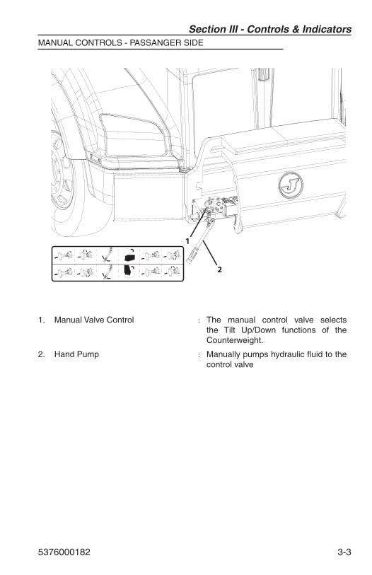
MANUAL CONTROLS - PASSANGER SIDE
2
1
1. Manual Valve Control : The manual control valve selects the Tilt Up/Down functions of the Counterweight.
2. Hand Pump : Manually pumps hydraulic fl uid to the control valve
Section III - Controls & Indicators
3-4 5376000182
THIS PAGE IS INTENTIONALLY LEFT BLANK
Section IV : Operation
5376000182 4-1
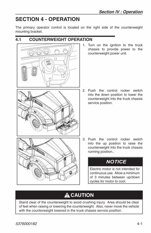
SECTION 4 - OPERATIONThe primary operator control is located on the right side of the counterweight mounting bracket.
4.1 COUNTERWEIGHT OPERATION
HL73
HL51
LOR
HI
LO 26 H
L
HL84
1. Turn on the ignition to the truck chassis to provide power to the counterweight power unit.
2. Push the control rocker switch into the down position to lower the counterweight into the truck chassis service position.
3. Push the control rocker switch into the up position to raise the counterweight into the truck chassis running position..
Electric motor is not intended for continuous use. Allow a minimum of 3 minutes between up/down cycles for motor to cool.
Stand clear of the counterweight to avoid crushing injury. Area should be clear of feet when raising or lowering the counterweight. Also, never move the vehicle with the counterweight lowered in the truck chassis service position.
�����
Section IV : Operation
4-2 5376000182
The operator may occasionally need to adjust the counterweight by adding or removing weight plates in the Adjustable Performance Counterweight.
Small Weight Plates ...................................................................97 lb each (Approx.)
Large Weight Plates .............................................................. 119 lb each (Approx.)
DO NOT EXCEED THE CHASSIS FRONT AXLE WEIGHT RATING (GAWR)
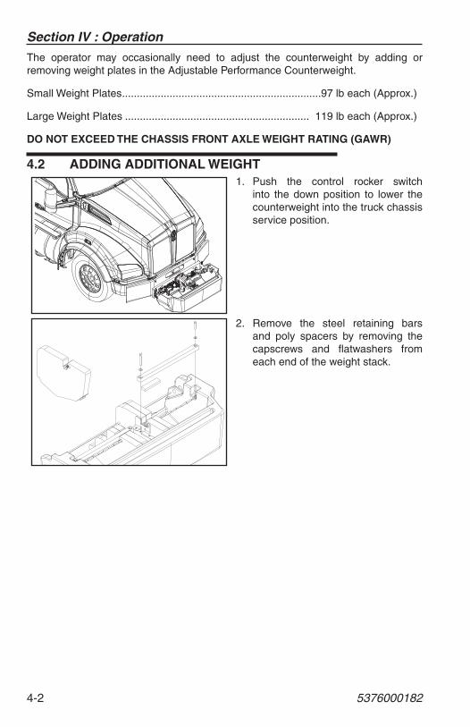
4.2 ADDING ADDITIONAL WEIGHT1. Push the control rocker switch
into the down position to lower the counterweight into the truck chassis service position.
2. Remove the steel retaining bars and poly spacers by removing the capscrews and fl atwashers from each end of the weight stack.
Section IV : Operation
5376000182 4-3
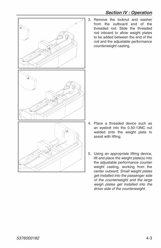
3. Remove the locknut and washer from the outboard end of the threaded rod. Slide the threaded rod inboard to allow weight plates to be added between the end of the rod and the adjustable performance counterweight casting.
4. Place a threaded device such as an eyebolt into the 0.50-13NC nut welded onto the weight plate to assist with lifting.
5. Using an appropriate lifting device, lift and place the weight plate(s) into the adjustable performance counter weight casting, working from the center outward. Small weight plates get installed into the passenger side of the counterweight and the large weigh plates get installed into the driver side of the counterweight.
Section IV : Operation
4-4 5376000182
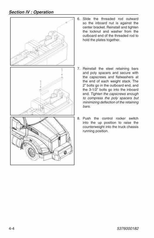
6. Slide the threaded rod outward so the inboard nut is against the center bracket. Reinstall and tighten the locknut and washer from the outboard end of the threaded rod to hold the plates together.
7. Reinstall the steel retaining bars and poly spacers and secure with the capscrews and fl atwashers at the end of each weight stack. The 2” bolts go in the outboard end, and the 3-1/2” bolts go into the inboard end. Tighten the capscrews enough to compress the poly spacers but minimizing defl ection of the retaining bars.
8. Push the control rocker switch into the up position to raise the counterweight into the truck chassis running position.
Section IV : Operation
5376000182 4-5
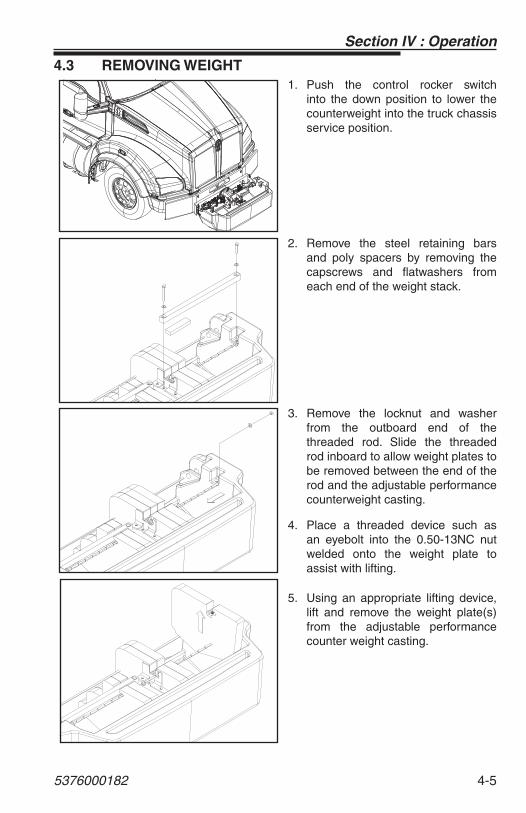
4.3 REMOVING WEIGHT1. Push the control rocker switch
into the down position to lower the counterweight into the truck chassis service position.
2. Remove the steel retaining bars and poly spacers by removing the capscrews and fl atwashers from each end of the weight stack.
3. Remove the locknut and washer from the outboard end of the threaded rod. Slide the threaded rod inboard to allow weight plates to be removed between the end of the rod and the adjustable performance counterweight casting.
4. Place a threaded device such as an eyebolt into the 0.50-13NC nut welded onto the weight plate to assist with lifting.
5. Using an appropriate lifting device, lift and remove the weight plate(s) from the adjustable performance counter weight casting.
Section IV : Operation
4-6 5376000182
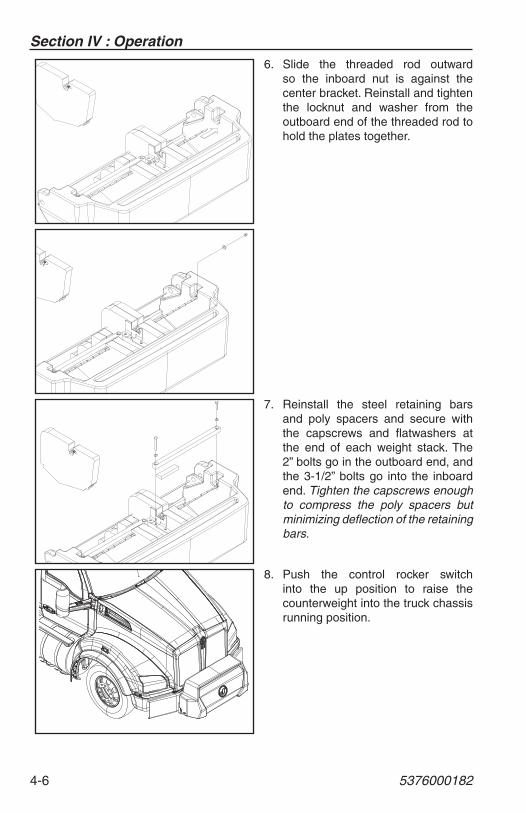
6. Slide the threaded rod outward so the inboard nut is against the center bracket. Reinstall and tighten the locknut and washer from the outboard end of the threaded rod to hold the plates together.
7. Reinstall the steel retaining bars and poly spacers and secure with the capscrews and fl atwashers at the end of each weight stack. The 2” bolts go in the outboard end, and the 3-1/2” bolts go into the inboard end. Tighten the capscrews enough to compress the poly spacers but minimizing defl ection of the retaining bars.
8. Push the control rocker switch into the up position to raise the counterweight into the truck chassis running position.
Section V : Manual Pump Operation
5376000182 5-1
SECTION 5 - MANUAL PUMP OPERATION
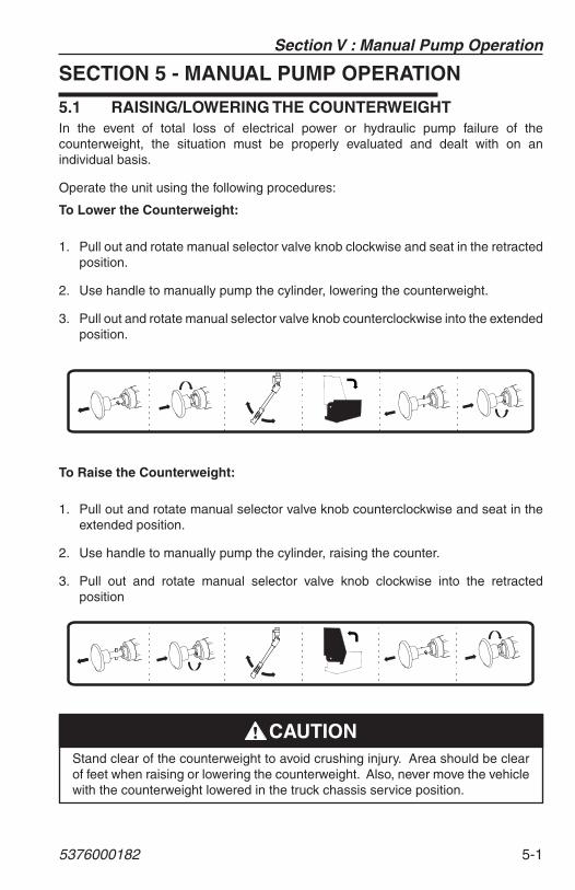
5.1 RAISING/LOWERING THE COUNTERWEIGHTIn the event of total loss of electrical power or hydraulic pump failure of the counterweight, the situation must be properly evaluated and dealt with on an individual basis.
Operate the unit using the following procedures:
To Lower the Counterweight:
1. Pull out and rotate manual selector valve knob clockwise and seat in the retracted position.
2. Use handle to manually pump the cylinder, lowering the counterweight.
3. Pull out and rotate manual selector valve knob counterclockwise into the extended position.
To Raise the Counterweight:
1. Pull out and rotate manual selector valve knob counterclockwise and seat in the extended position.
2. Use handle to manually pump the cylinder, raising the counter.
3. Pull out and rotate manual selector valve knob clockwise into the retracted position
Stand clear of the counterweight to avoid crushing injury. Area should be clear of feet when raising or lowering the counterweight. Also, never move the vehicle with the counterweight lowered in the truck chassis service position.
�����
Section V : Manaul Pump Operation
5-2 5376000182
THIS PAGE IS INTENTIONALLY LEFT BLANK
Section VI - Maintenance
5376000182 6-1
SECTION 6 - MAINTENANCE
INTRODUCTIONService the product in accordance with the maintenance schedule on the following pages.
Wear all the protective clothing and personal safety devices issued to you or called for by job conditions.
DO NOT wear loose clothing or jewelry that can get caught on controls or moving parts.
Intervals shown are for normal usage and conditions. Adjust intervals for abnormal usage and conditions.
Check all lubricant levels when lubricant is cool. For ease of fi lling hydraulic reservoir, use a funnel with a hose or fl exible tube for best results.
Use only safe practices when maintaining this equipment. Always turn off the ignition switch before reaching into pinch areas.
Place Do Not Operate Tags on the ignition switch and the steering wheel before attempting to perform any service or maintenance. Remove the key and disconnect battery leads.
CUT/CRUSH/BURN HAZARD. Do not perform service or maintenance on the machine with the engine running, with the exception of the hydraulic return fi lter indicator checks.
�������
The hydraulic system operates at extremely high and potentially dangerous pressures. The operator must relieve any system pressure before disconnecting or removing and portion of the system.
�������
Section VI - Maintenance
6-2 5376000182
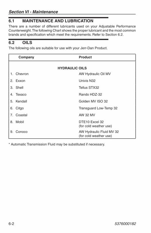
6.1 MAINTENANCE AND LUBRICATIONThere are a number of different lubricants used on your Adjustable Performance Counterweight. The following Chart shows the proper lubricant and the most common brands and specifi cation which meet the requirements. Refer to Section 6.2.
6.2 OILSThe following oils are suitable for use with your Jerr-Dan Product.
Company Product
HYDRAULIC OILS
1. Chevron AW Hydraulic Oil MV
2. Exxon Univis N32
3. Shell Tellus STX32
4. Texaco Rando HDZ-32
5. Kendall Golden MV ISO 32
6. Citgo Transguard Low-Temp 32
7. Coastal AW 32 MV
8. Mobil DTE10 Excel 32(for cold weather use)
9. Conoco AW Hydraulic Fluid MV 32(for cold weather use)
* Automatic Transmission Fluid may be substituted if necessary.
Section VI - Maintenance
5376000182 6-3
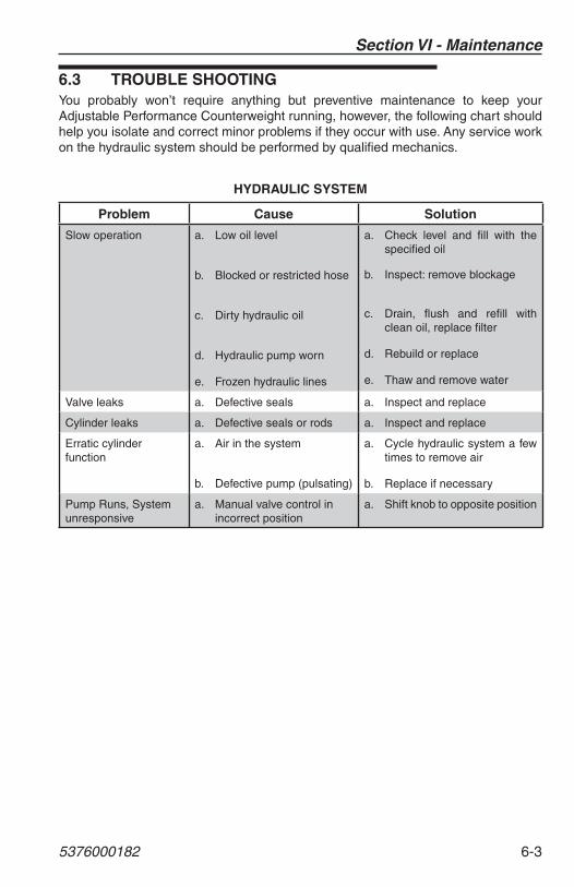
6.3 TROUBLE SHOOTINGYou probably won’t require anything but preventive maintenance to keep your Adjustable Performance Counterweight running, however, the following chart should help you isolate and correct minor problems if they occur with use. Any service work on the hydraulic system should be performed by qualifi ed mechanics.
HYDRAULIC SYSTEM
Problem Cause Solution
Slow operation a. Low oil level
b. Blocked or restricted hose
c. Dirty hydraulic oil
d. Hydraulic pump worn
e. Frozen hydraulic lines
a. Check level and fi ll with the specifi ed oil
b. Inspect: remove blockage
c. Drain, fl ush and refi ll with clean oil, replace fi lter
d. Rebuild or replace
e. Thaw and remove water
Valve leaks a. Defective seals a. Inspect and replace
Cylinder leaks a. Defective seals or rods a. Inspect and replace
Erratic cylinder function
a. Air in the system
b. Defective pump (pulsating)
a. Cycle hydraulic system a few times to remove air
b. Replace if necessary
Pump Runs, Systemunresponsive
a. Manual valve control in incorrect position
a. Shift knob to opposite position
Section VI - Maintenance
6-4 5376000182
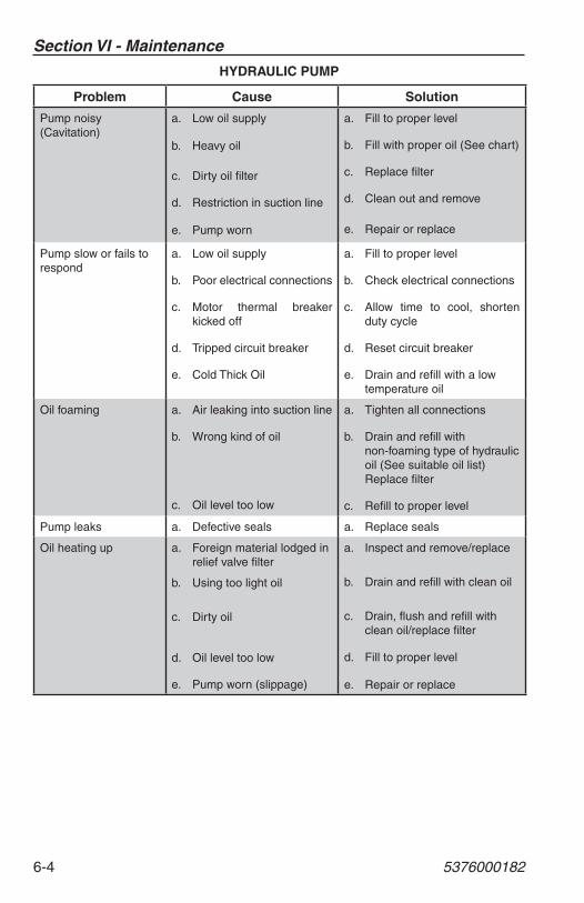
HYDRAULIC PUMP
Problem Cause Solution
Pump noisy (Cavitation)
a. Low oil supply
b. Heavy oil
c. Dirty oil fi lter
d. Restriction in suction line
e. Pump worn
a. Fill to proper level
b. Fill with proper oil (See chart)
c. Replace fi lter
d. Clean out and remove
e. Repair or replace
Pump slow or fails to respond
a. Low oil supply
b. Poor electrical connections
c. Motor thermal breaker kicked off
d. Tripped circuit breaker
e. Cold Thick Oil
a. Fill to proper level
b. Check electrical connections
c. Allow time to cool, shorten duty cycle
d. Reset circuit breaker
e. Drain and refi ll with a low temperature oil
Oil foaming a. Air leaking into suction line
b. Wrong kind of oil
c. Oil level too low
a. Tighten all connections
b. Drain and refi ll with non-foaming type of hydraulic oil (See suitable oil list) Replace fi lter
c. Refi ll to proper level
Pump leaks a. Defective seals a. Replace seals
Oil heating up a. Foreign material lodged in relief valve fi lter
b. Using too light oil
c. Dirty oil
d. Oil level too low
e. Pump worn (slippage)
a. Inspect and remove/replace
b. Drain and refi ll with clean oil
c. Drain, fl ush and refi ll with clean oil/replace fi lter
d. Fill to proper level
e. Repair or replace
Section VII : Specifi cations
5376000182 7-1
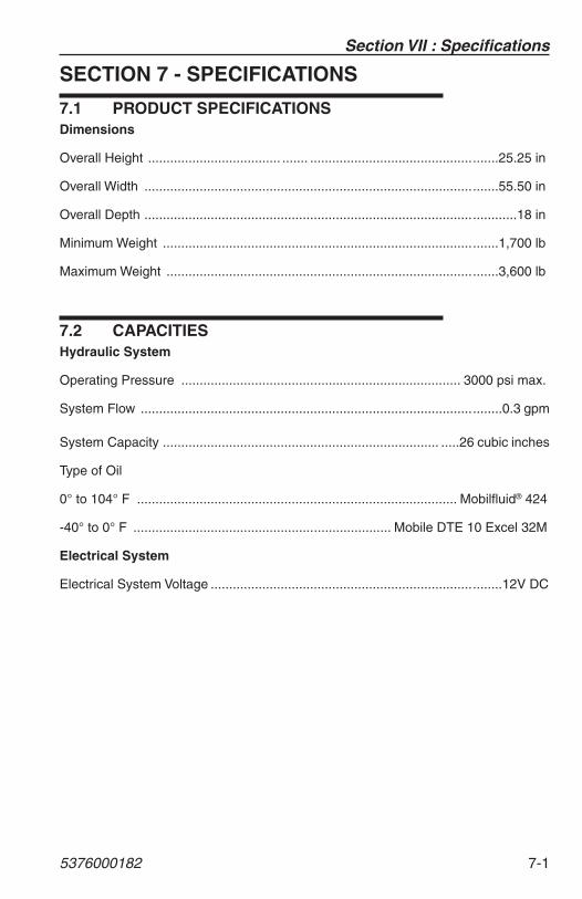
SECTION 7 - SPECIFICATIONS
7.1 PRODUCT SPECIFICATIONSDimensions
Overall Height .................................... ....... ...................................................25.25 in
Overall Width ................................................................................................55.50 in
Overall Depth .....................................................................................................18 in
Minimum Weight ...........................................................................................1,700 lb
Maximum Weight ..........................................................................................3,600 lb
7.2 CAPACITIESHydraulic System
Operating Pressure ........................................... ................................. 3000 psi max.
System Flow ..................................................................................................0.3 gpm
System Capacity ........................................................................... .....26 cubic inches
Type of Oil
0° to 104° F ....................................................................................... Mobilfl uid® 424
-40° to 0° F ...................................................................... Mobile DTE 10 Excel 32M
Electrical System
Electrical System Voltage ...............................................................................12V DC

Section VII : Specifi cations
7-2 5376000182
THIS PAGE IS INTENTIONALLY LEFT BLANK

Inspection, Maintenance and Repair Log
Serial Number
Date Comments
Inspection, Maintenance and Repair Log
Date Comments
To Product Owner: If you now own but ARE NOT the original purchaser of the product covered by this manual, we would like to know who you are. For the purpose of receiving safety-related bulletins, it is very important to keep Jerr-Dan Corporation updated with the current ownership of all Jerr-Dan products. Jerr-Dan maintains owner information for each Jerr-Dan product and uses this information in cases where owner notifi cation is necessary. Please use this form to provide Jerr-Dan with updated information with regard to the current ownership of Jerr-Dan products. Please return completed form to the Jerr-Dan Product Safety & Reliability Department via facsimile or mail to address as specifi ed below.
Thank You,Product Safety & Reliability DepartmentJerr-Dan Corporation13224 Fountainhead PlazaHagerstown, MD 21742USATelephone: +1-717-485-6591Fax: +1-301-745-3713
NOTE: Leased or rented units should not be included on this form.
Mfg. Model :
Serial Number :
Previous Owner :
Address :
Country : Telephone : ( )
Date of Transfer :
Current Owner :
Address :
Country : Telephone : ( )
Who in your organization should we notify?
Name :
Title :
TRANSFER OF OWNERSHIP

THIS PAGE IS INTENTIONALLY LEFT BLANK

www.jerr-dan.com
5376000182- 0
13224 Fountainhead PlazaHagerstown, MD 21742Phone (717) 597-7111
Phone (800) 926-9666