Embed Size (px)
Citation preview

OPERATION AND MAINTENANCE MANUAL
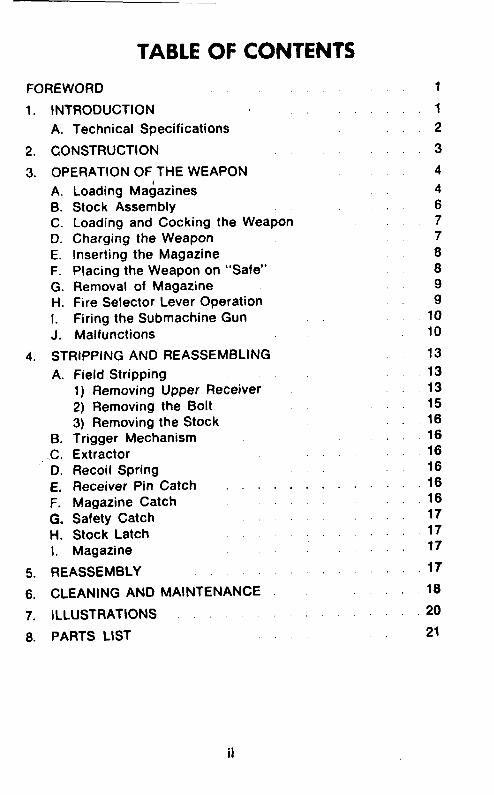
TABLE OF CONTENTS
FOREWORD
1. INTRODUCTION
A. Technical Specifications
2. CONSTRUCTION
3. OPERATION OF THE WEAPON
A. Loading Magazines B. Stock Assembly C. Loading and Cocking the Weapon D. Charging the Weapon
E. Inserting the Magazine F. Placing the Weapon on “Safe” G. Removal of Magazine H. Fire Selector Lever Operation
I. Firing the Submachine Gun
J. Malfunctions
4. STRIPPING AND REASSEMBLING
A.
B. .c. D.
E. F. 0. H. I.
Field Stripping 1) Removing Upper Receiver 2) Removing the Bolt 3) Removing the Stock Trigger Mechanism Extractor Recoil Spring Receiver Pin Catch . . Magazine Catch Safety Catch Stock Latch Magazine
5. REASSEMBLY
6. CLEANING AND MAINTENANCE
7. ILLUSTRATIONS
8. PARTS LIST
. . . .
1
1
2
3
4
4 6 7 7 8 8 9 9
10 10
13
13 13 15 16 16 16 16 16 16 17 17 17
17
18
20
21
ii
FOREWORD
This manual is published for the information and guidance of
personnel whose duties involve the use, maintenance and repair
of the Ml0 SMG and the Ml1 SMG. Disassembly, assembly, clean-
ing and minor repairs may be undertaken in the field.
In all cases where the nature of the repair or adjustment is beyond
the scope of facilities of the unit, the Manufacturer should be in-
formed in order that trained personnel with suitable tools and
equipment may be provided.
1. INTRODUCTION
The Ingram Model 10 and Model 11 represent a significant break
through in compact submachine gun design. The Ml0 is available
in 9MM Para and .45 ACP calibers, the Ml1 in .380 ACP caliber.
Both Models are light in weight, durable steel construction and
easy to fire, either semi-automatic or full automatic.
The compact size of the Ml0 makes it especially suitable for
tank crews, gun and mortar crews, etc., and its selective fire
capability makes it an excellent weapon for police use.
The addition of a noise suppressor further enhances the per-
formance, reducing the noise and eliminating muzzle flash.
The weapon operates on the straight blowback principle and is
magazine fed.
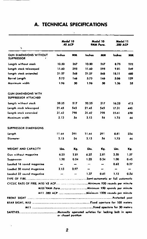
A. TECHNICAL SPECIFICATIONS
Model 10 Model 10 Model 11 .45 AC? 9MM Cam. JR0 AC?
GUN DIMENSIONS WlliiOUl SUPPRESSOR I
Length without stock
Length stock telescoped
Length stock cxtendod
Barrel Length
Maximum width
Inches MM Inchmr MM Inches
10.50 267 10.50 267 8.75
11.60 295 11.60 295 9.81
21.57 548 21.57 548 18.11
5.75 146 5.75 146 5.06
1.96 50 1.96 50 1.36
MM
222
249
460
129
35
GUN DIMENSIONS WITH
SUPPRESSOR ATTACHED
Length without stock
Length stock telescoped
Length stock extended
Maximum width
20.35 517 20.35 517 16.25 413
21.45 545 21.45 545 17.31 440
31.42 798 31.42 798 25.61 650
2.13 54 2.13 54 1.75 44
SUPPRESSOR DIMENSIONS
Length 11.44 291 11.44 291 8.81
Diameter 2.13 54 2.13 54 1.75
224
44
WEIGHT AND CAPACITY
Gun without mogozinc
Suppressor
Loodcd 16 round magazine
LoAded 30 round magazine
Loaded 32 round mogozine
lbs.
6.25
1.20
2.15
-
Kg. lbs. Kg. Lbr.
2.81 6.25 2.81 3.50
0.54 1.20 034 1.00
- 0.62
0.97 - - -
- 1.37 0.61 1.12
Kg.
1.57
0.45
0.27
0.54
TYPE OF FIRE ............................................................................ Semi-automatic or full automatic
CYCLIC RATE OF FIRE, M10/45 ACP.. ...................................... Minimum 950 rounds per minute
MlO/PMM Paro.. ................................ Minimum 950 rounds Per minute
Ml 1 380 ACP ................................ Minimum 1200 rounds per minute
FRONT SIGHT .......................................................................................................... Protected post
REAR SIGHT, Ml0 ........................................................................ fixed opertur. for 100 maters
Ml1 ............................................................................ Fixed opwtura for 50 meters
SAFETIES.. .............................................. Manually operated safeties for locking bolt in open or closed position
2

2. CONSTRUCTION
The weapon consists of the foliowing major components:
Barrel, Receiver, Bolt, Frame, Firing
Mechanism, Magazine, and Extendable Stock
A sling swivel is attached to the barrel and receiver assembly.
The front end of the barrel is threaded to accept a suppressor.
The receiver is fitted with a fixed front sight and houses the bolt,
recoil spring, buffer and ejector rod. The frame carries the re-
ceiver group, trigger mechanism, magazine housing, stock guide,
and safety assembly.
The trigger mechanisms consist of sear, sear spring, selector
lever, retainer, trip, trigger, trigger pin, trigger spring, and dis-
connector.
The stock is designed to telescope into the frame when not in use
thereby reducing the overall size of the weapon.
The bolt assembly on the Model 10 and Model 11 is fitted with
a cocking handle. Both models have fixed firing pins. The ex
tractor on the Model 10 operates on the leaf spring principle while
the Model 11 utilizes a compression spring.
The magazine for the Model 10 .45 ACP and Model 11 380 ACP
caliber are both of the double column single position feed type,
while the Model 10/9MM Para caliber is of the double column
two position feed type.

3. OPERATION OF THE WFAPON
A. loading Magazines
9 MM Para- rounds s wacity
Hold the magazine in one hand, insert the cartridge, one at a
time through thl; -wuth of the magazine ensuring that the base of
each cartridge 13 zuainst the rear of the magazine. (See Fig. 1)
FIG. 1 Pushing Cartridge Under Magazine Feed Lips
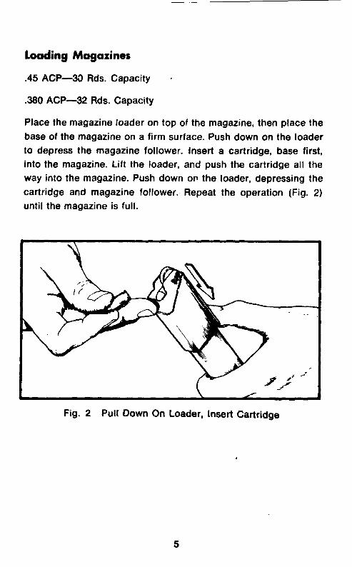
loading Magazines
.45 ACP-W Rds. Capacity s
380 ACP-32 Rds. Capacity
Place the magazine loader on top of the magazine, then place the
base of the magazine on a firm surface. Push down on the loader
to depress the magazine follower. Insert a cartridge, base first,
into the magazine. Lift the loader, and push the cartridge all the
way into the magazine. Push down on the loader, depressing the
cartridge and magazine follower. Repeat the operation (Fig. 2)
until the magazine is full.
Fig. 2 Pull Down On Loader, Insert Cartridge
5

6. Stock Assembly
Hold weapon in left hand, with right hand press inwards on right
side of wire form butt near the pivot to allow wire form stock to
rotate clockwise to normal firing position. (See Fig. 3)
Still holding weapon in left hand depress stock latch button and
extend stock assembly using right hand. (See Fig. 4)
Fig. 3 Disengaging Wire Form from Retaining Pin
Fig. 4 Extending Stock Assembly
6
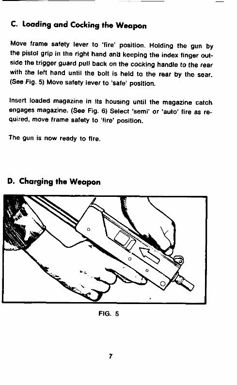
C. loading and Cocking the Weapon
Move frame safety lever to ‘fire’ position. Holding the gun by
the pistol grip in the right hand and keeping the index finger out-
side the trigger guard pull back on the cocking handle to the rear
with the left hand until the bolt is held to the rear by the sear.
(See Fig. 5) Move safety lever to ‘safe’ position.
Insert loaded magazine in its housing until the magazine catch
engages magazine. (See Fig. 6) Select ‘semi’ or ‘auto’ fire as re-
quired, move frame safety to ‘fire’ position.
The gun is now ready to fire.
D. Charging the Weapon
FIG. 5

E. Inserting the Magazine
FIG. 6
F. Placing the Weapon on “Safe”
The safety is located on the right of the underside of the frame,
it moves front to back, front is the ‘fire’ position and back is the
‘safe’ position. (See Fig. 7)
FIG. 7
8
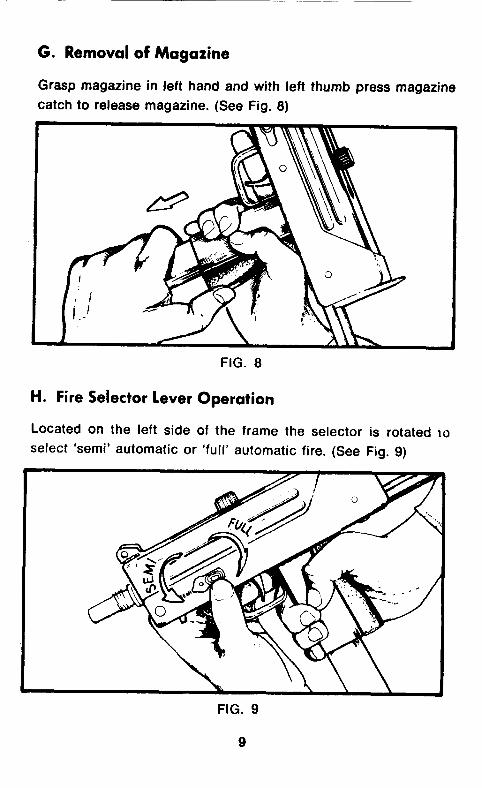
G. Removal of Magazine
Grasp magazine in left hand and with left thumb press magazine
catch to release magazine. (See Fig. 8)
FIG. 8
H. Fire Selector lever Operation
Located on the left side of the frame the selector is rotated 10
select ‘semi’ automatic or ‘full’ automatic fire. (See Fig. 9)
FIG. 9
9
I. Firing the Submachine Gun
As the bolt is moved back to the cocked position, the recoil spring
is compressed and the sear engages the sear notch of the bolt.
When the trigger is pressed, the sear releases the bolt, which is
driven forward by the recoil spring. During this forward move-
ment, the bolt strips a cartridge from the magazine into the
chamber. The bolt continues forward and fires the cartridge.
When the cartridge is fired, the chamber pressure forces the
bullet out of the muzzle of the barrel. At the same time, this
pressure overcomes the forward movement of the bolt and starts
it to the rear. By the time the bolt and empty case have moved to
the rear far enough to open the rear of the chamber, the bullet has
left the barrel, and the chamber pressure has diminished. (In the
submachine gun, the chamber pressure is relatively low and the
bolt is relatively heavy; this eliminates the need for positive lock-
ing and unlocking.) During the rearward movement of the bolt, the
empty cartridge case is extracted and ejected, the recoil spring
is compressed and the top round in the magazine moves up
against the lips of the magazine. The rearward movement of the
bolt is stopped by contact with the buffer plate.
J. Malfunctions
Malfunctions are usually the result of worn parts or improper care
of the gun. A knowledge of how the gun functions enables the
user to classify and correct the malfunction. Listed below are the
types of malfunctions which might occur.
1. Failure to Feed. The top cartridge in the magazine is not po-
sitioned up and in front of the bolt. Most malfunctions of the
submachine gun are failures to feed caused by a defective or
dirty magazine.
10
2. Failure to Chamber. The top cartridge from the magazine is not
seated in the chamber.
3. Failure to Fire. The cartridge is chambered but does not fire.
4. Failure to Extract. If the cartridge fires, the chamber pressure
will normally push the empty cartridge case out of the
chamber. If the cartridge case is not completely removed
from the chamber and the bolt is retracted, then there is a
failure to extract. This malfunction seldom occurs.
5. Failure to Eject. The empty cartridge case is not ejected from
the weapon.
6. Failure to Cock. If the bolt is retracted and is not held by the
sear, or if, during firing, the bolt does not move to the rear
far enough to clear the top cartridge in the magazine, the gun
fails to cock.
11
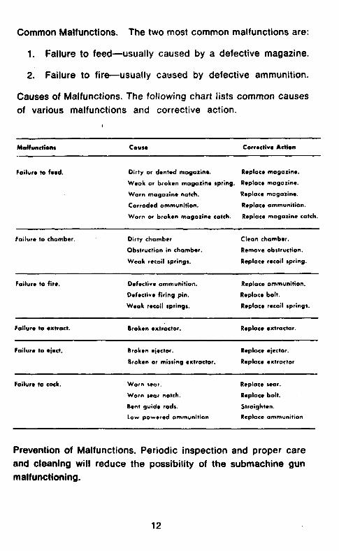
Common Malfunctions. The two most common malfunctions are:
1. Failure to feed-usually caused by a defective magazine.
2. Failure to fire-usually caused by defective ammunition.
Causes of Malfunctions. The following chart lists common causes
of various malfunctions and corrective action.
Foilwe to fe*d. Dirty or dented moga~in~. Roplaco magazine.
Weak or broken magazine spring. Replace magazine.
Worn magazine notch. Replace magoxine.
Corroded ammunition. Replace ammunition.
Worn or broken magazine catch. Replace mogorinc catch.
Foilura to chombcr. Dirty chamber
Obstruction in chamber.
Weak recoil springs.
Clean chombcr.
Remove obstruction.
Replace recoil spring.
Failure to fire. D*fectiw ammunition.
Def*ctiw firing pin.
Weak recoil springs.
Replace ammunition.
Replace bolt.
Replace recoil springs.
Foilur. to l xhoct.
Failure to l jwt. Broken cicctor. Replace oiactor.
Broken or misting extractor. Replace extractor
F&lure to cock. Worn scar.
Worn sear notch.
Bent guide rods.
Low powered ammunition
Replace scar.
Replace bolt.
Straighten.
Replace ammunition
Prevention of Malfunctions. Periodic inspection and proper care
and cleaning will reduce the possibility of the submachine gun
malfunctioning.
12
4. STRIPPING AND REASSEMBLING
The Model 10 and Model 11 have been designed so that no special
tools are necessary in order to’strip or reassemble the weapon.
Stripping
Before starting to strip the weapon remove the magazine and
check the barrel chamber by looking through the EJECTION
PORT to make sure there are no live rounds in the weapon.
A. Field Stripping consists of
1) Removing Upper Receiver (Cock Weapon)
Push receiver pin catch back and remove receiver pin. (See Fig.
10). On alternate configuration where there is no receiver pin
catch, a sharp push on the receiver pin is all that is required for
removal.
Push upper receiver from frame. (See Fig. 11)
13
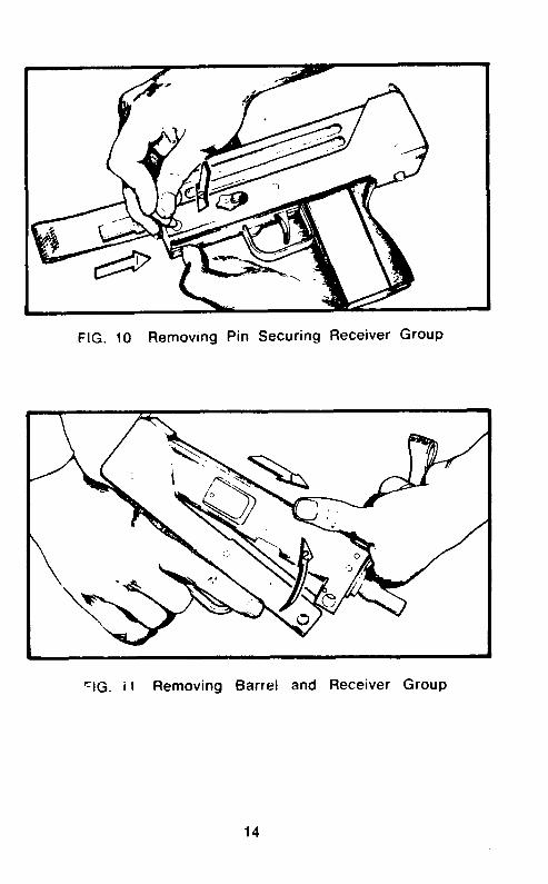
FIG. 10 Removing Pin Securing Receiver Group
‘IG. il Removing Barrel and Receiver Group
14
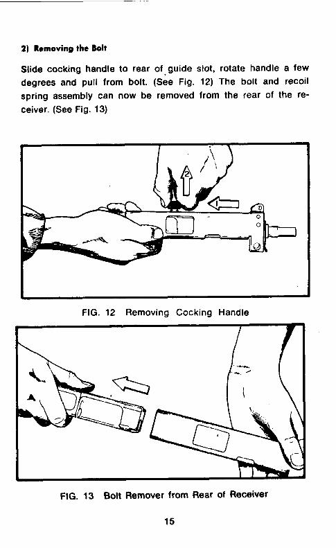
2) Removing the Bolt
Slide cocking handle to rear of-guide slot, rotate handle a few
degrees and pull from bolt. (See Fig. 12) The bolt and recoil
spring assembly can now be removed from the rear of the re-
ceiver. (See Fig. 13)
FIG. 12 Removing Cocking Handle
FIG. 13 Bolt Remover from Rear of Receiver
3) Removing the Stock
To remove stock, depress stock latch button and keeping pressure
on button pull stock completely out. (see Figs. 3 and 4)
The procedure mentioned above is generally sufficient for
normal maintenance and cleaning. If necessary to clean trigger
mechanism, removal is as follows:
B. Trigger Mechanism
Lift retainer and remove selector lever, this aldo allows removal
of sear, sear spring and tripping lever. Push trigger pin out of the
left side for removal of trigger or torsion spring. Note: for re-
assembly, free arm of torsion spring is located on rear side of
disconnector. Disconnector may be replaced by using a pin
punch to remove spring pin.
C. Extractor
Use pin punch to remove extractor spring pin.
D. Recoil Spring
Compress spring and move guide rod clear of bolt and use pin punch to remove spring pin from guide rod.
E. Receiver Pin Catch
Use pin punch to remove spring pin.
F. Magazine Catch
Use flat bladed screw-driver to remove screw in hand grip for access to catch.
16

G. Safety Catch
Use pin punch to remove catch spring pin.
H. Stock Latch
Press down lightly at center of pin and slide to either side to re-
move retaining pin. Invert frame and latch will drop out.
I. Magazine
M1./9MM Poro, Ml 1 380 ACP
Depress stud in floor plate and slide plate from magazine case.
Keeping finger over the bottom of the magazine to prevent the
magazine spring from flying out. Remove the magazine spring and
the magazine follower.
M10/45 ACP
Lift the tab in the floor plate by inserting a screw-driver in the
hole. Remove base plate, placing the finger over the bottom of
the magazine to prevent the magazine spring from flying out.
Remove the magazine spring and the magazine follower.
NOTE: To achieve the proper functioning when reassembling
the Ml1 and M10/45 magazine ensure that the slope of
the top coil of the spring corresponds with the slope on
the follower.
5. REASSEMBLY
Items are reassembled in the reverse order to the stripping pro-
cedure.
17
6. CLEANING AND
It is essential for reliable operation and performance. that the
weapon receive careful maintenance. It should be cleaned at
the end of each day’s firing.
The Gun need only be “field stripped” for this maintenance.
Barrel and Receiver Group Cleaning
A.
B.
C.
D.
E.
Bolt
A.
6.
Use cleaning rod, patch and solvent. Stubborn residue can
be removed with a bristle bore brush.
Swab bore with patch saturated in solvent.
Use solvent saturated patch and swab inside of receiver to
remove residue.
Use clean dry patch to dry barrel and inside of receiver
group.
Dampen patch with light oil and swab barrel and receiver.
Assembly Cleaning
Remove powder residue with solvent and patch.
Wipe all surfaces of bolt to remove carbon. The bolt face
should be completely free of carbon and other residue.
C. Wipe dry and apply a light coat of oil.
Frame Assembly Group Cleaning
A. Remove residue build-up on exposed surfaces with solvent-
soaked cloth.
18

B. Clean around the lockwork. The weapon is designed to
tolerate some dirt in the frame group but excessive dirt will
impair operation. Detail cleaning is required after pro-
longed operation or improper’ functioning of weapon.
C. Wipe dry and use oily patch to coat exposed metal areas
with light film of oil.
Magazine Cleaning
A. Inspect magazine for damaged areas. Damaged magazines
should be discarded.
B. Clean lip area and top of the follower.
C. Wipe with oily patch.
Suppressor Cleaning
The suppressor requires no other maintenance apart from
ensuring that the bore is kept clear of obstructions. Inspection
must be made with the suppressor removed from the weapon.
The front end cap of the suppressor is replaceable. It should be
replaced atter each 500 rounds of firing or sooner if the noise
level has increased significantly.
19
a e .$i T
-. t -____
20
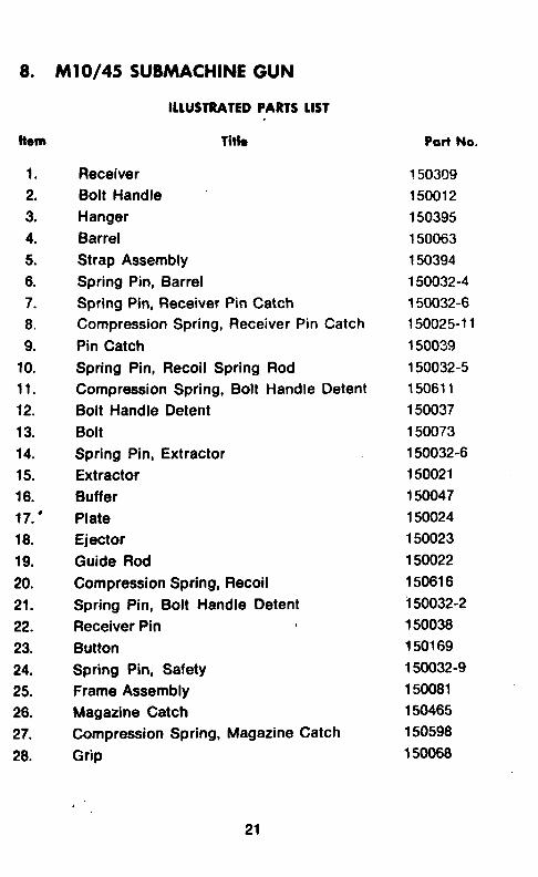
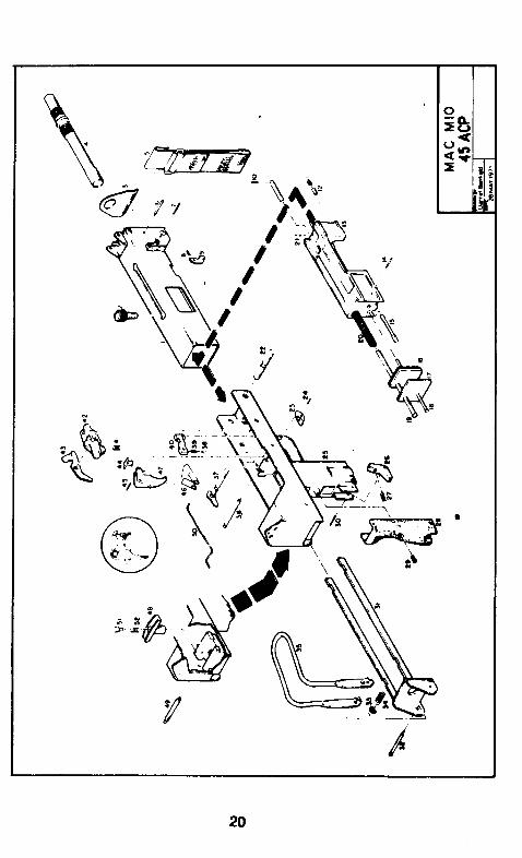
8. MO/45 SUBMACHINE GUN
Item Title Port No.
1. Receiver 150309
2. Bolt Handle 150012
3. Hanger 150395
4. Barrel 150063
5. Strap Assembly 150394
6. Spring Pin, Barrel 150032-4
7. Spring Pin, Receiver Pin Catch 150032-6
8. Compression Spring, Receiver Pin Catch 150025-11
9. Pin Catch 150039
10. Spring Pin, Recoil Spring Rod 150032-5
11. Compression Spring, Bolt Handle Detent 150611
12. Bolt Handle Detent 150037
13. Bolt 150073
14. Spring Pin, Extractor 150032-6
15. Extractor 150021
16. Buffer 150047
17. ’ Plate 150024
16. Ejector 150023
19. Guide Rod 150022
20. Compression Spring, Recoil 150616
21. Spring Pin, Bolt Handle Detent i50032-2
22. Receiver Pin 150038
23. Button 150169
24. Spring Pin, Safety 150032-g
25. Frame Assembly 150081
26. Magazine Catch 150465
27. Compression Spring, Magazine Catch 150598
28. Grip 150068
ILLUSfRAlED PARTS LIST
21

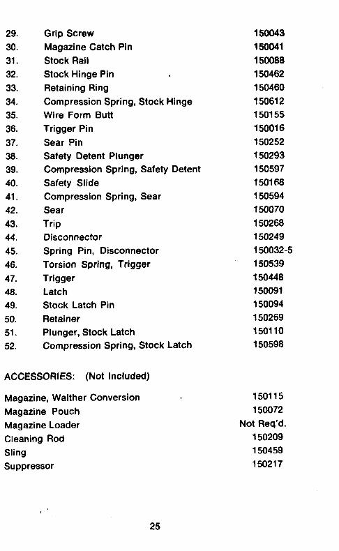
29. Grip Screw
30. Magazine Catch Pin
31. Stock Rail
32. Stock Hinge Pin ’
33. Retaining Ring
34. Compression Spring, Stock Hinge
35. Wire Form Butt
36. Trigger Pin
37. Sear Pin
38. Safety Detent Plunger
39. Compression ‘Spring, Safety Detent
40. Safety Slide
41. Compression Spring, Sear
42. Sear
43. Trip
44. Disconnector
45. Spring Pin, Disconnector
46. Torsion Spring, Trigger
47. Trigger
46. Latch
49. Stock Latch Pin
50. Retainer
51. Plunger, Stock Latch
52. Compression Spring, Stock Latch
ACCESSORIES: (Not Included)
Magazine 150111
Magazine Pouch 150072
Magazine Loader 150245
Cleaning Rod 150209
Sling 150459 Suppressor 150216
150043
, 150041
150068
156462
150460
150612
150155
150016
156252
150293
150597
150168
150594
150070
150268
150249
150032-S
150539
150448
150091
150094
150269
15011 o-1
150598
22
23
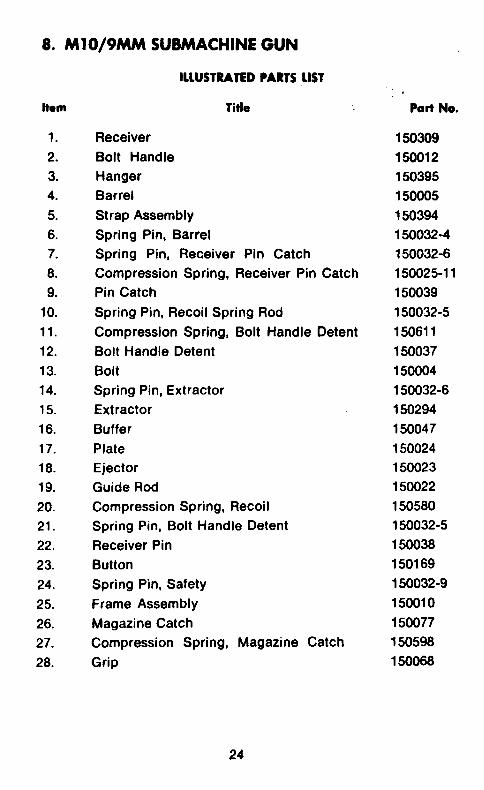
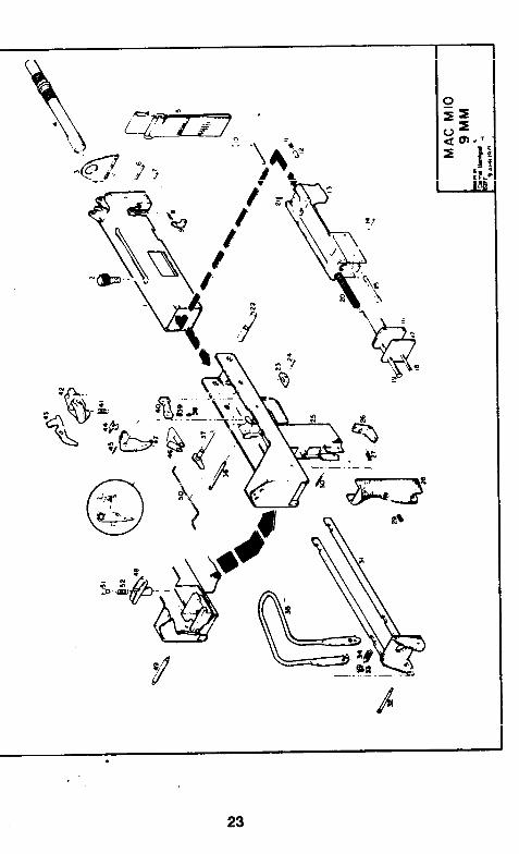
8. M10/9MM SUBMACHINE GUN
Itom Title Pati No.
1. Receiver 150309 2. Bolt Handle 150012 3. Hanger 150395 4. Barrel 150005
5. Strap Assembly 150394 6. Spring Pin, Barrel 150032-4
7. Spring Pin, Receiver Pin Catch 150032-6
6. Compression Spring, Receiver Pin Catch 150025-l 1
9. Pin Catch 150039
10. Spring Pin, Recoil Spring Rod 150032-5
11. Compression Spring, Bolt Handle Detent 150611
12. Bolt Handle Detent 150037
13. Bolt 150004
14. Spring Pin, Extractor 150032-6
15. Extractor 150294
16. Buffer 150047
17. Plate 150024
18. Ejector 150023
19. Guide Rod 150022
20. Compression Spring, Recoil 150580
21. Spring Pin, Bolt Handle Detent 150032-5
22. Receiver Pin 150038
23. Button 150169
24. Spring Pin, Safety 150032-g
25. Frame Assembly 150010
26. Magazine Catch 150077
27. Compression Spring, Magazine Catch 150598
28. Grip 150068
MUSTRATED ?ARTS LIST
24
29. Grip Screw 159043
30. Magazine Catch Pin 166041
31. Stock Rail 150088
32. Stock Hinge Pin 150462
33. Retaining Ring 150460
34. Compression Spring, Stock Hinge 150612
35. Wire Form Butt 150155
36. Trigger Pin 150016
37. Sear Pin 150252
36. Safety Detent Plunger 150293
39. Compression Spring, Safety Detent 150597
40. Safety Slide 150166
41. Compression Spring, Sear 150594
42. Sear 150070
43. Trip 150268
44. Disconnector 150249
45. Spring Pin, Disconnector 150032-5
46. Torsion Spring, Trigger 150539
47. Trigger 150448
46. Latch 150091
49. Stock Latch Pin 150094
50. Retainer 150269
51. Plunger, Stock Latch 150110
52. Compression Spring, Stock Latch 150598
ACCESSORIES: (Not Included)
Magazine, Walther Conversion
Magazine Pouch
Magazine Loader
Cleaning Rod
Sling
Suppressor
150115
150072
Not Req’d.
150209
150459
150217
25
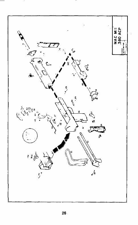
26
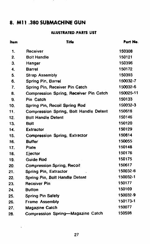
8. Ml 1 ,380 SUBMACHINE GUN
ILLlJSTRAtED. PARTS LIST
Item Title
1.
2.
3.
4.
5.
6.
7.
6.
9.
10. 11.
12.
13.
14.
15.
16.
17.
18.
19.
20. 21.
22.
23.
24.
25.
26. 27.
28.
Receiver
Bolt Handle
Hanger
Barrel Strap Assembly
Spring Pin, Barrel
Spring Pin, Receiver Pin Catch
Compression Spring, Receiver Pin Catch
Pin Catch
Spring Pin, Recoil Spring Rod
Compression Spring, Bolt Handle Detent
Bolt Handle Detent
Bolt
Extractor
Compression Spring, Extractor
Buffer
Plate
Ejector
Guide Rod
Compression Spring, Recoil Spring Pin, Extractor
Spring Pin, Bolt Handle Detent
Receiver Pin
Button
Spring Pin Safety
Frame Assembly
Magazine Catch
Compression Spring-Magazine Catch
27
Part No.
150308 150121
150396
150172
150393
150032-7
150032-6
150025-l 1
150133
150032-3
150616
150146
150120
150129
150614
150055 150148
150176
150175
150617 150032-6
150032-l
150177
150169
150032-g
150173-l
150877
150598
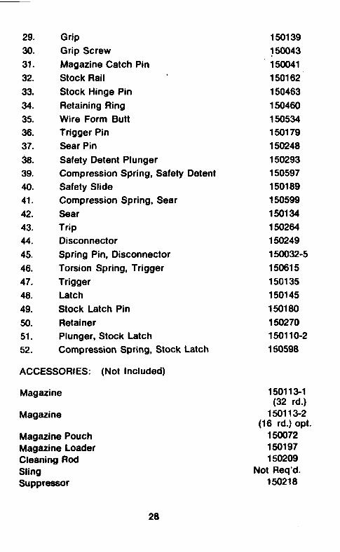
29. Grip
30. Grip Screw
31. Magazine Catch Pin
32. Stock Rail
33. Stock Hinge Pin
34. Retaining Ring
35. Wire Form Butt
36. Trigger Pin
37. Sear Pin
38. Safety Detent Plunger
39. Compression Spring, Safety Detent
40. Safety Slide
41. Compression Spring, Sear
42. Sear
43. Trip
44. Disconnector
45. Spring Pin, Disconnector
46. Torsion Spring, Trigger
47. Trigger
46. Latch
49. Stock Latch Pin
50. Retainer
51. Plunger, Stock Latch
52. Compression Spring, Stock Latch
ACCESSORIES: (Not Included)
Magazine
Magazine
Magazine Pouch Magazine Loader Cleaning Rod Sling Suppressor
150139
150043
150041
150162
156463
150466
150534 150179
150248
150293
150597
150189
150599
156134
150264
150249
150032-S
150615
150135
150145
156180
150270 15011 o-2
150598
150113-l (32 rd.)
150113-2 (16 rd.) opt.
150072 150197 150209
Not Req’d. 150218
28

ITEM TITLE M IO/45 Ml0/9MM MII
IA RECEIVER 150634-l 150634-l 150633-I
22A RECEIVER PIN 150628-I l50628-I -
23A RECEIVER PIN - -- 150628-2
22 A ( MIO-OMM , MO-45 1 23A (MII)
ALTERNATE RECEIVER PIN CONFIGURATION
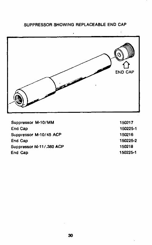
SUPPRESSOR SHOWING REPLACEABLE END CAP
Suppressor M-lo/MM 150217 End Cap 150225-l Suppressor M-10/45 ACP 150216 End Cap 150225-2 Suppressor M-l l/.360 ACP 150218 End Cap 150225-l
30

150461-BODY
. .
FOLLOWER
MIO-45ACP
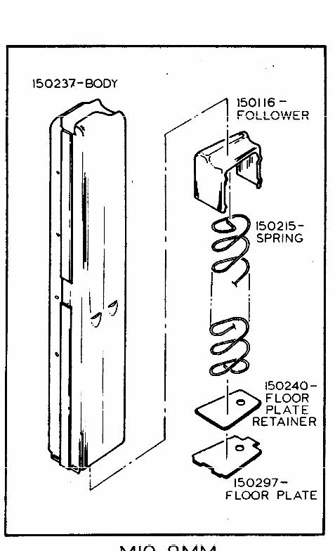
150237-BODY
1 150116 - .
f
FOLLOWER 8
I
<3 150240 -
0 FLOOR PLATE
RETAINER
FLOOR PLATE
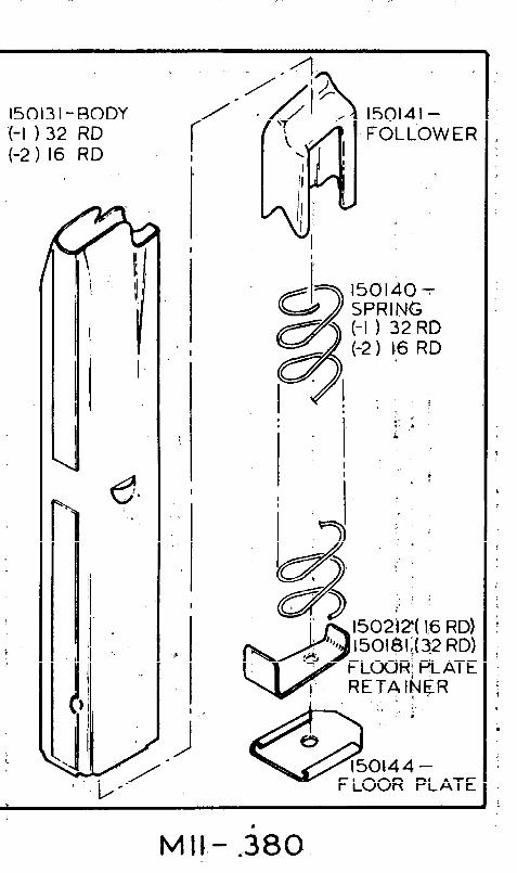
150131-BODY ‘(-I ) 32 RD t-2 1 16 RD
\
i
f I
I
. I
150141- FOLLOWER
150140 -t- SPRING (-I ) 32 RD (-2 1 I,6 RD
0144 - FLOOR PLATE
M II,- -380
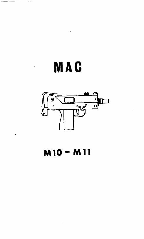
MAC
Ml0 - Ml1