Embed Size (px)
Citation preview

REVISION A 3/20/2017
Operation and Maintenance Manual
5 1/8” LT Full Bore Plug Valve
MSI – A Division of Dixie Iron Works, Ltd.
300 W. Main St.
Alice, TX 78332
www.diwmsi.com
(800) 242-0059

TABLE OF CONTENTS
SECTION 1 MSI QUALITY ................................................................................................................. 1
SECTION 2 SAFETY ............................................................................................................................. 2
SECTION 3 PRODUCT OVERVIEW ................................................................................................. 3
3.1 GENERAL DESCRIPTION ................................................................................................................... 3
SECTION 4 ENGINEERING DATA ................................................................................................... 4
4.1 STANDARD MATERIALS OF CONSTRUCTION..................................................................................... 4
4.2 WORKING ENVIRONMENT ................................................................................................................ 4
4.3 DESIGN & TESTING .......................................................................................................................... 4
4.4 OPERATING TORQUE ........................................................................................................................ 4
4.5 ACTUATOR OUTPUT ......................................................................................................................... 5
4.6 MAXIMUM FLOW RATE .................................................................................................................... 5
4.7 RECOMMENDED LUBRICANTS .......................................................................................................... 6
4.8 LUBRICATION CAPACITY ................................................................................................................. 6
4.9 DIMENSIONS & MASSES ................................................................................................................... 7
SECTION 5 DISASSEMBLY & ASSEMBLY..................................................................................... 8
5.1 DISASSEMBLY .................................................................................................................................. 8
5.2 CLEANING ........................................................................................................................................ 8
5.3 INSPECTION ...................................................................................................................................... 9
5.4 ASSEMBLY ....................................................................................................................................... 9
5.5 POST-ASSEMBLY GREASE CHARGING ............................................................................................ 12
5.6 ACTUATOR MOUNTING .................................................................................................................. 12
SECTION 6 MAINTENANCE & PRESERVATION ....................................................................... 13
6.1 MAINTENANCE LUBRICATION ........................................................................................................ 13
6.2 INSPECTION .................................................................................................................................... 13
6.3 PRESERVATION AND STORAGE ....................................................................................................... 13
APPENDIX A PARTS LISTS ................................................................................................................. 14
APPENDIX B ACTUATOR ASSEMBLIES ......................................................................................... 17

1
SECTION 1 MSI QUALITY

2
SECTION 2 SAFETY
This equipment is intended for use in high-pressure and high flow well service applications. High pressure
equipment, if not used and maintained properly, can cause serious injury or death and damage to equipment and
property.
Only operate the valve in the full open or full close position, never flow through the valve in a partially open
state as severe erosion may occur and create a hazardous situation.
Not taking proper precautions and failing to perform routine maintenance and inspections can also contribute to
loss of well control, and such loss could cause serious injury or death and damage to equipment and property.
ALL OPERATORS AND MAINTENANCE PERSONNEL SHOULD BE THOROUGHLY TRAINED
IN THE SAFE OPERATION, MAINTENANCE, AND INSPECTION OF THIS EQUIPMENT.

3
SECTION 3 PRODUCT OVERVIEW
3.1 General Description
Since 2002, the MSI 5 1/8” LT plug valve has been operated daily in some of the most severe environments the
industry has to offer such as: wellhead protection/isolation, frac stacks, and frac manifold trailers. The valve is
engineered to provide exceptional value to the operator by reducing cost of ownership and maximizing
throughput of wellhead operations. Compared to a gate valve the MSI plug valve:
Is more compact and lightweight.
Is more durable in abrasive environments due to minimal particle intrusion to body.
Requires less grease to maintain in operating environments.
Permits repair without removing valve from the tree.
Permits rapid open or close cycles.
This valve is only offered with assisted actuation in the form of handwheel or hydraulic actuators. Handwheel
actuators utilize worm gear reduction and are available as single speed or two speed units. Hydraulic actuators
permit remote operation to keep personnel away from pressurized equipment, which is required in some cases.
Connections typically provided include API® Flange and Stud Flange, Grant Prideco™ box and pin premium
drill connections, or our own ACME box and pin straight thread. Other connections may be applied by request.
MSI also offers the 5” plug valve with dual pockets when a compact installation with redundant sealing
mechanisms is desired. Such configurations eliminate a connection point where two valves are normally used,
and permit inlets to be added for directly introducing additional flow streams between the closure mechanisms.
4
SECTION 4 ENGINEERING DATA
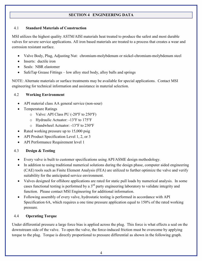
4.1 Standard Materials of Construction
MSI utilizes the highest quality ASTM/AISI materials heat treated to produce the safest and most durable
valves for severe service applications. All iron based materials are treated to a process that creates a wear and
corrosion resistant surface.
Valve Body, Plug, Adjusting Nut: chromium-molybdenum or nickel-chromium-molybdenum steel
Inserts: ductile iron
Seals: NBR elastomer
SafeTap Grease Fittings – low alloy steel body, alloy balls and springs
NOTE: Alternate materials or surface treatments may be available for special applications. Contact MSI
engineering for technical information and assistance in material selection.
4.2 Working Environment
API material class AA general service (non-sour)
Temperature Ratings
o Valve: API Class PU (-20°F to 250°F)
o Hydraulic Actuator: -13°F to 175°F
o Handwheel Actuator: -13°F to 230°F
Rated working pressure up to 15,000 psig
API Product Specification Level 1, 2, or 3
API Performance Requirement level 1
4.3 Design & Testing
Every valve is built to customer specifications using API/ASME design methodology.
In addition to using traditional numerical solutions during the design phase, computer aided engineering
(CAE) tools such as Finite Element Analysis (FEA) are utilized to further optimize the valve and verify
suitability for the anticipated service environment.
Valves designed for offshore applications are rated for static pull loads by numerical analysis. In some
cases functional testing is performed by a 3rd
party engineering laboratory to validate integrity and
function. Please contact MSI Engineering for additional information.
Following assembly of every valve, hydrostatic testing is performed in accordance with API
Specification 6A, which requires a one time pressure application equal to 150% of the rated working
pressure.
4.4 Operating Torque
Under differential pressure a large force bias is applied across the plug. This force is what effects a seal on the
downstream side of the valve. To open the valve, the force-induced friction must be overcome by applying
torque to the plug. Torque is directly proportional to pressure differential as shown in the following graph.

5
4.5 Actuator Output
Actuators are sized based on manufacturer data to provide at least 125% of the measured operating torque. This
design factor compensates for increases in torque that can occur due to adjustment of the nut, lubrication,
temperature, alignment of shaft with plug, and condition of parts; to name a few contributing factors.
Actuator Max Output Torque (ft-lbf) Design Factor Turns Open-Close
Hydraulic 9150 (at 3000 psig hyd) 1.40 1/4 hydraulically
Single Speed Handwheel 8900 (at 80 lbf rim-pull) 1.36 162 on handwheel
Dual Speed Handwheel 8450 (at 80 lbf rim-pull) 1.30 25 on handwheel1
1 Approximate number of turns to break seal at high torque setting + turns to complete opening at high speed setting.
4.6 Maximum Flow Rate
Typical applications for the MSI 5 1/8” plug valve involve high flowing rates of abrasive media such as sand or
proppant. Erosion will occur at varying rates according primarily to the geometric characteristics of the media
and flow velocity. The user should consider the economic and safety impact of choosing an operational flow
rate.

6
4.7 Recommended Lubricants
MSI recommends the following lubricants for the assembly of the valve. Refer to Section 5.4 for specific
applications details.
ASSEMBLY
Application Lubricant
Plug, Inserts, Adjusting Nut, Seals Val-Tex 972
Threads* Copper Anti-Seize Lubricant
*For threaded end connections use an API rotary connection thread compound.
MSI recommends the following plug valve greases for maintenance of the valve. Other greases may be used
but MSI strongly recommends a rigorous evaluation prior to implementing the grease in field operations.
Contact MSI for assistance in grease selection or for information on other qualified greases.
MAINTENANCE
Application Lubricant
General Service (-20°F to 600°F) Val-Tex 972 Stick Grease
Low-Temp Service (-50°F to 375°F) Val-Tex 750 Stick Grease
CAUTION: Many plug valve grease manufacturers offer both “stick” and “bulk” packaged greases. Bulk
typically is a softer grease than stick formulations. High adhesion and cohesion properties are necessary to
establish a seal between the plug and inserts. Use only grease with an NLGI classification of 6.
4.8 Lubrication Capacity
Approximately 55 in3 of void space exists in a fully assembled valve. For proper operation the voids must be
charged with plug valve stick grease. A ‘K’ size grease stick is approximately 18.5 in3 (1.5” diameter x 10.5”
length).
GREASE REQUIREMENT
Application Lubricant
Rebuild 3-4 ‘K’ sticks
Field Maintenance Up to 4 ‘K’ sticks1
1 Depends on charge level at time of lubrication.

7
4.9 Dimensions & Masses
Approximate weights for typical valve configurations (does not include actuator weight):
API flange = 1150 lbs
ACME thread = 850 lbs
Approximate weights for complete actuator assembly:
Handwheel actuator single speed = 250 lbs
Handwheel actuator dual speed = 275 lbs
Hydraulic actuator = 250 lbs

8
SECTION 5 DISASSEMBLY & ASSEMBLY
If possible repair work should be performed in a clean environment free of dirt, rust, paint, and protected from
inclement weather. Foreign materials readily adhere to grease and may cause damage to the parts. The operator
should at a minimum be wearing safety glasses, steel toe boots, and gloves during these activities.
5.1 Disassembly
Verify that all lifting and supporting equipment is capable of safely handling the weight of the valve prior to
attempting service. Contact MSI for assistance in determining valve weight if you are unsure.
1. Secure the valve to a sturdy frame or table capable of withstanding the load and orient the valve so
that the adjusting nut can be removed.
CAUTION: In some cases pressure may become trapped in the valve cavity even after it has been removed
from service. Trapped pressure is a safety hazard that could cause bodily injury if a sudden release occurs.
MSI recommends venting grease fittings prior to disassembly.
2. Remove the screw (or grease fitting) and washer from the plug.
3. Using a valve operating bar or 1” diameter rod engage the holes in the adjusting nut and remove by
rotating in a CCW direction.
4. Steps specific to valve generation.
a. GEN I Adjusting Nut:
i. Remove the seal ring.
ii. Extract the inserts.
b. GEN II Adjusting Nut:
i. The integral adjusting nut will extract the inserts as it is rotated out of engagement
with the valve.
5. Remove the plug. An eyebolt may be installed into the tapped hole to aid this step.
NOTE: Make certain to verify the thread pitch before inserting the eyebolt. Regular plugs utilize a
3/4"-10 UNC thread; GreaSeal plugs utilize a 3/4"-16 UNF thread. Be extremely careful not to damage
the GreaSeal plug port.
6. Remove all seals being careful not to scratch or ding any surfaces immediately around the seal.
a. Discard all seals if the valve has been in service.
7. Body grease fittings do not normally need to be removed. If a fitting is removed plug the port to
prevent foreign material from entering.
5.2 Cleaning
Thoroughly clean all parts with a suitable solvent to remove grease and dirt. Do not use heavy abrasives or
scraping tools as that could result in irreparable damage to the parts.

9
5.3 Inspection
All inspections should take place in a clean and well-lit work area. Non-marring surfaces should be provided
for setting parts on.
Examine all metal parts for damage such as dings, wear, erosion, and pitting; especially on the sealing surfaces.
Replace as needed.
Examine the button head of all grease fittings, replace those that are damaged. See assembly section for grease
fitting installation requirements.
5.4 Assembly
Prior to re-building the valve it is recommended all parts be thoroughly inspected and cleaned, especially reused
parts. Scratches, dings, wear, and pitting may result in failure of the valve to hold pressure. If any parts need to
be dressed prior to assembly perform this work in a different area to prevent contaminating the assembly area.
1. Orient the valve body with the pocket cavity facing up.
2. Apply a film of stick grease in the plug seal cavity of the valve body, install the plug seal with the
groove facing out, then pack seal groove and immediate area with stick grease.
3. Apply a thin film of stick grease on the outer surfaces of the plug (green areas highlighted below)
and gently insert it hex end first into the valve body. An eyebolt may be used to assist lifting the
plug.
NOTE: Make certain to verify the thread pitch before inserting the eyebolt. Regular plugs utilize a
3/4"-10 UNC thread; GreaSeal plugs utilize a 3/4"-16 UNF thread. Be extremely careful not to
damage the GreaSeal plug port.
4. Apply a film of stick grease in the plug seal cavity of the adjusting nut, install the plug seal with the
groove facing out, then pack seal groove and immediate area with stick grease..
5. Place insert seals into the face groove and pack with stick grease to keep them in place.
6. Apply a coat of thread anti-seize compound to the adjusting nut threads and/or the mating threads in
the valve body pocket.
a. GEN I Adjusting Nut:
i. Lower inserts into valve body making certain the pins engage the slots on the sides of the
inserts.
10
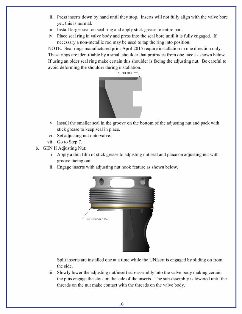
ii. Press inserts down by hand until they stop. Inserts will not fully align with the valve bore
yet, this is normal.
iii. Install larger seal on seal ring and apply stick grease to entire part.
iv. Place seal ring in valve body and press into the seal bore until it is fully engaged. If
necessary a non-metallic rod may be used to tap the ring into position.
NOTE: Seal rings manufactured prior April 2015 require installation in one direction only.
These rings are identifiable by a small shoulder that protrudes from one face as shown below.
If using an older seal ring make certain this shoulder is facing the adjusting nut. Be careful to
avoid deforming the shoulder during installation.
v. Install the smaller seal in the groove on the bottom of the adjusting nut and pack with
stick grease to keep seal in place.
vi. Set adjusting nut onto valve.
vii. Go to Step 7.
b. GEN II Adjusting Nut:
i. Apply a thin film of stick grease to adjusting nut seal and place on adjusting nut with
groove facing out.
ii. Engage inserts with adjusting nut hook feature as shown below.
Split inserts are installed one at a time while the UNIsert is engaged by sliding on from
the side.
iii. Slowly lower the adjusting nut/insert sub-assembly into the valve body making certain
the pins engage the slots on the side of the inserts. The sub-assembly is lowered until the
threads on the nut make contact with the threads on the valve body.

11
7. Rotate the adjusting nut CCW by hand just until the thread starts align. This is usually indicated by
a gradual lifting then sudden drop.
8. After the thread starts are aligned rotate the nut CW by hand slowly until there is an abrupt increase
in resistance. This resistance indicates initial part contact.
9. Keep rotating the nut CW using a valve bar until the flow bore of the inserts align concentrically to
the flow bore of the valve. It may be necessary to perform this steps in incremental stages of
tightening the nut, rotating the plug, and tightening the nut again. As the parts come closer to
alignment running clearances become very small. Rotating the plug during this step will help
displace excess grease and permit these clearances to close.
NOTE: Correct adjustment of the nut is essential to a properly functioning valve. If the nut is too
loose there may be insufficient pre-load on the inserts to reliably initiate sealing, too tight and operating
torque increases to unacceptable levels. Adjust the nut to achieve approximately 125 ft-lbf torque to
rotate the plug. When using the GEN II adjusting nut, taper locking may be prevented by slightly
loosening the nut. This will engage the shelf of the inserts and prevent movement toward the apex of
the pocket.
10. Once the alignment is satisfactory move plug to open position and drift the valve. Fine adjustments
may be made to allow drifting.
NOTE: Drifting bars should be in accordance with dimensions and tolerances specified in API 6A.
For a 5 1/8” nominal bore size the large diameter of the drift shall not exceed 5.117”.
11. Apply thread anti-seize to retaining screw or grease fitting.
c. Regular Plug:
i. Install washer and screw and tighten snug.
d. GreaSeal Plug:
i. Install washer and grease fitting then tighten to 125 ft-lbs torque.
12. Install body grease fittings if needed then tighten to 125 ft-lbs torque.
CAUTION: The metal-to-metal sealing design of the SafeTap grease require high contact pressure at a conical
interface to maintain a leak-free seal. If any foreign material is present at this interface permanent damage to
the sealing face in the valve body may occur during tightening. Take extreme care in keeping the port and
fitting completely clean. Do not use sealing aids such as PTFE tape or paste on the SafeTap grease fitting.

12
5.5 Post-Assembly Grease Charging
Prior to use or storage the voids in the valve cavity must be filled with stick grease. This step ensures readiness
for operation by displacing moisture, providing a reserve of lubricant, and evacuating pockets of air. Sufficient
charging is measured by volume of grease injected and pressure. 3 to 4 sticks are typically required to fully
charge the valve cavities after rebuilding the valve. During injection the grease pressure gauge will indicate a
rise in pressure, keep pumping until this pressure reaches a peak and drops, or pressure builds to at least 3000
psi. Stop pumping when either of those events occur, this indicates the immediate cavities are fully charged
with grease and excess is flowing into the bore.
1. With plug in open position inject plug valve grease through the body fitting closest to the adjusting
nut.
2. Actuate plug one full cycle.
3. Repeat step 1 & 2 for the second body fitting.
NOTE: Grease may exit the weep hole in the plug during injection. This is normal, once this occurs
stop injecting grease.
4. If a GreaSeal plug is utilized inject plug valve grease through the plug fitting.
5.6 Actuator Mounting
After the valve has been fully assembled and drifted the actuator is ready for mounting and final alignment.
Use appropriate lifting equipment to avoid damage and personal injury. Specific information regarding actuator
parts and fastener torques may be found in the appendix.
1. Orient valve with exposed hex of plug facing up and in open position.
2. Lift actuator and carefully align the parts to the plug.
3. Completely lower the actuator making certain it is not in a bind.
4. Install mounting bolts and tighten to the recommended torque values.
5. Actuate valve to verify 90° rotation and that plug indexes consistently from full open to full close.
6. Adjust position stops as necessary.
7. Drift valve to verify final alignment.

13
SECTION 6 MAINTENANCE & PRESERVATION
The following are general maintenance guidelines, actual maintenance practices should be tailored to the
specifics of the usage frequency and severity of operations.
6.1 Maintenance Lubrication
Trouble-free function of the valve depends to a large degree on lubrication. As mentioned in Section 4.7,
specialized greases have been developed for plug valves used in high pressure and high temperature service.
These greases contain friction-reducing additives to keep operating torque at reasonable levels. Do not use
grease that is not intended for use in plug valves.
Reference Section 5.5 for field greasing procedures. If line pressure is present the greasing pressure must be
greater than line pressure but shall not exceed the rated working pressure of the valve. Always verify that the
equipment is rated for the anticipated pressure.
6.2 Inspection
It is advised to frequently inspect the valve and establish maintenance routines that suit the service conditions.
During operation the valve is subject to erosion and corrosion damage which are highly influenced by many
factors. Erosion can cause material loss to the point that the equipment fails to function or actually becomes
unsafe. MSI Specification 9-2014 should be referenced for minimum wall thickness requirements.
6.3 Preservation and Storage
Between Jobs:
Lubricate valve to purge contaminants from the critical areas.
Flush valve with clean water to remove debris and chemical residue, thoroughly dry.
Apply an aerosol corrosion inhibitor to the exposed, unpainted metal surfaces.
Every 3 – 6 months:
Re-grease and operate by cycling the plug several times from open to close, returning to open.
Test valve to verify seals are in good condition.
Drain test fluid, thoroughly dry, then apply an aerosol corrosion inhibitor to the exposed, unpainted
metal surfaces.
Greater than 6 months:
Disassemble valve and discard all elastomer seals and grease.
Rebuild valve according to Section 5.4 using new elastomers then test.
Drain test fluid, thoroughly dry, then apply an aerosol corrosion inhibitor to the exposed, unpainted
metal surfaces.
Always transport and store plug valves in the full open position to protect the critical sealing surfaces from
damage.
14
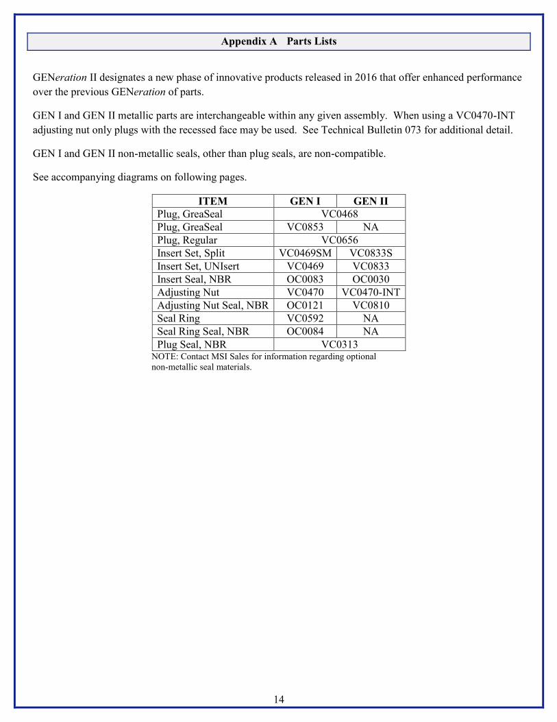
Appendix A Parts Lists
GENeration II designates a new phase of innovative products released in 2016 that offer enhanced performance
over the previous GENeration of parts.
GEN I and GEN II metallic parts are interchangeable within any given assembly. When using a VC0470-INT
adjusting nut only plugs with the recessed face may be used. See Technical Bulletin 073 for additional detail.
GEN I and GEN II non-metallic seals, other than plug seals, are non-compatible.
See accompanying diagrams on following pages.
ITEM GEN I GEN II
Plug, GreaSeal VC0468
Plug, GreaSeal VC0853 NA
Plug, Regular VC0656
Insert Set, Split VC0469SM VC0833S
Insert Set, UNIsert VC0469 VC0833
Insert Seal, NBR OC0083 OC0030
Adjusting Nut VC0470 VC0470-INT
Adjusting Nut Seal, NBR OC0121 VC0810
Seal Ring VC0592 NA
Seal Ring Seal, NBR OC0084 NA
Plug Seal, NBR VC0313 NOTE: Contact MSI Sales for information regarding optional
non-metallic seal materials.

15
GEN I Typical Assembly

16
GEN II Typical Assembly

17
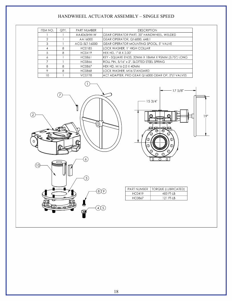
Appendix B Actuator Assemblies
HYRAULIC
18
HANDWHEEL ACTUATOR ASSEMBLY – SINGLE SPEED

19
HANDWHEEL ACTUATOR ASSEMBLY – DUAL SPEED

MSI – A Division of Dixie Iron Works, Ltd.
300 W. Main St.
Alice, TX 78332
www.diwmsi.com
(800) 242-0059
(361) 664-6597