Embed Size (px)
Citation preview

DCImage Acquisition System
Installation & User’s guide

This user’s guide may not be copied, photocopied, translated, modified, orreduced to any electronic medium or machine-readable form, in whole, or in part,without the prior written consent of Dantec Dynamics A/S.
Publication no.: 9040U4164 Date: July 1, 20043nd edition printed in 2004.© 2004 by Dantec Dynamics A/S, Tonsbakken 16-18, DK-2740 Skovlunde,Denmark. All rights reserved.
All trademarks referred to in this document are registered by their owners.

Installation and User’s guide for DC Image Acquisition System. i
Table of contentsTable of contents................................................................................................................................................i
1. Warranties & disclaims ........................................................................................................................1-1
1.1 Dantec Dynamics License Agreement .................................................................................................1-11.1.1 Grant of License..........................................................................................................................1-11.1.2 Upgrades .....................................................................................................................................1-11.1.3 Copyright ....................................................................................................................................1-11.1.4 Limited Warranty........................................................................................................................1-11.1.5 Limitation of Liability ................................................................................................................1-21.1.6 Product Liability .........................................................................................................................1-21.1.7 Governing Law and Proper Forum .............................................................................................1-21.1.8 Questions ....................................................................................................................................1-3
1.2 Laser safety..........................................................................................................................................1-3
1.3 CCD sensor warranty..........................................................................................................................1-3
2. DC Image Acquisition System..............................................................................................................2-1
2.1 Overview..............................................................................................................................................2-1
2.2 Cameras supported by the DC Imaging System ..................................................................................2-12.2.1 HiSense MkII camera .................................................................................................................2-12.2.2 FlowSense 2M camera................................................................................................................2-22.2.3 HiSense 4M camera ....................................................................................................................2-2
2.3 Illumination systems ............................................................................................................................2-22.3.1 New wave solo pulsed lasers ......................................................................................................2-22.3.2 Shutter device .............................................................................................................................2-2
3. Installation .............................................................................................................................................3-1
3.1 Unpacking the system..........................................................................................................................3-1
3.2 System installation...............................................................................................................................3-13.2.1 Frame grabber(s) and synchronisation board Driver installation................................................3-13.2.2 Frame grabber(s) and synchronisation board installation ...........................................................3-13.2.3 Analog Input software and hardware installation .......................................................................3-23.2.4 DC Image Acquisition Software installation ..............................................................................3-23.2.5 Uninstall the DC Image Acquisition software ............................................................................3-2
3.3 Connections .........................................................................................................................................3-33.3.1 Steps by steps procedure.............................................................................................................3-33.3.2 Connections diagram ..................................................................................................................3-43.3.3 Analog Input ...............................................................................................................................3-4
4. Using the DC Image Acquisition software ..........................................................................................4-1
4.1 First time use .......................................................................................................................................4-1
4.2 Online acquisition window..................................................................................................................4-34.2.1 Tab: Acquisition Control ............................................................................................................4-3
Image acquisition ............................................................................................................................... 4-4View control ....................................................................................................................................... 4-6Storage control ................................................................................................................................... 4-7

ii Installation and User’s guide for DC Image Acquisition System.
4.2.2 Tab: Timing Setup ..................................................................................................................... 4-7Trigger control related parameters...................................................................................................... 4-7
4.2.3 Frame grabber settings (Tabs: FG1 Info and FG2 Info) ............................................................ 4-84.2.4 A/D Setup................................................................................................................................... 4-9
A/D Setup control ............................................................................................................................... 4-9Trigger settings ................................................................................................................................. 4-10Channel 1 settings............................................................................................................................. 4-10Channel 2 settings............................................................................................................................. 4-10
4.2.5 Fail-safe function ..................................................................................................................... 4-10
5. Troubleshooting.................................................................................................................................... 5-1
6. Technical specifications ....................................................................................................................... 6-1
Installation and User’s guide for DC Image Acquisition System. 1-1
1. Warranties & disclaims1.1 Dantec Dynamics License Agreement
This License Agreement is concluded between you (either an individual or acorporate entity) and Dantec Dynamics A/S (“Dantec”). Please read all terms andconditions of this License Agreement before opening the disk package. When youbreak the seal of the software package and/or use the software enclosed, you agreeto be bound by the terms of this License Agreement.
1.1.1 Grant of LicenseThis License Agreement permits you to use one copy of the Dantec softwareproduct supplied to you (the “Software”) including documentation in written orelectronic form. The Software is licensed for use on a single computer and/orelectronic signal processor, and use on any additional computer and/or electronicsignal processor requires the purchase of one or more additional License(s). TheSoftware's component parts may not be separated for use on more than onecomputer or more than one electronic signal processor at any time. The primaryuser of the computer on which the Software is installed may also use the Softwareon a portable or home computer. This License is your proof of License to exercisethe rights herein and must be retained by you. You may not rent or lease theSoftware.
1.1.2 UpgradesThis License Agreement shall apply to any and all upgrades, new releases, bugfixes, etc. of the Software which are supplied to you. Any such upgrade etc. may beused only in conjunction with the version of the Software you have alreadyinstalled, unless such upgrade etc. replaces that former version in its entirety andsuch former version is destroyed.
1.1.3 CopyrightThe Software (including text, illustrations and images incorporated into theSoftware) and all proprietary rights therein are owned by Dantec or Dantec’ssuppliers, and are protected by the Danish Copyright Act and applicableinternational law. You may not reverse assemble, decompile, or otherwise modifythe Software except to the extent specifically permitted by applicable law withoutthe possibility of contractual waiver. You are not entitled to copy the Software orany part thereof. However you may either (a) make a copy of the Software solelyfor backup or archival purposes, or (b) transfer the Software to a single hard disk,provided you keep the original solely for backup purposes. You may not copy theUser’s Guide accompanying the Software, nor print copies of any userdocumentation provided in “on-line” or electronic form, without Dantec’s priorwritten permission.
1.1.4 Limited WarrantyYou are obliged to examine and test the Software immediately upon your receiptthereof. Until 30 days after delivery of the Software, Dantec will deliver a newcopy of the Software if the medium on which the Software was supplied (e.g. adiskette or a CD-ROM) is not legible.

1-2 Installation and User’s guide for DC Image Acquisition System.
A defect in the Software shall be regarded as material only if it has an effect on theproper functioning of the Software as a whole, or if it prevents operation of theSoftware. If until 90 days after the delivery of the Software, it is established thatthere is a material defect in the Software, Dantec shall, at Dantec's discretion,either deliver a new version of the Software without the material defect, or remedythe defect free of charge or terminate this License Agreement and repay theLicense fee received against the return of the Software. In any of these events theparties shall have no further claims against each other. Dantec shall be entitled toremedy any defect by indicating procedures, methods or uses ("work-arounds")which result in the defect not having a significant effect on the use of the Software.
The Software was tested prior to delivery to you. However, software is inherentlycomplex and the possibility remains that the Software contains bugs, defects andinexpediences which are not covered by the warranty set out immediately above.Such bugs etc. shall not constitute due ground for termination and shall not entitleyou to any remedial action. Dantec will endeavour to correct all bugs etc. insubsequent releases of the Software.
The Software is licensed "as is" and without any warranty, obligation to takeremedial action or the like thereof in the event of breach other than as stipulatedabove. It is therefore not warranted that the operation of the Software will bewithout interruptions, free of defects, or that defects can or will be remedied.
1.1.5 Limitation of LiabilityNeither Dantec nor its distributors shall be liable for any indirect damagesincluding without limitation loss of profits, or any incidental, special or otherconsequential damages, even if Dantec is informed of their possibility. In no eventshall Dantec's total liability here under exceed the License fee paid by you for theSoftware.
1.1.6 Product LiabilityDantec shall be liable for injury to persons or damage to objects caused by theSoftware in accordance with those rules of the Danish Product Liability Act whichcannot be contractually waived. Dantec disclaims any liability in excess thereof.
1.1.7 Governing Law and Proper ForumThis License Agreement shall be governed by and construed in accordance withDanish law. The sole and proper forum for the settlement of disputes here undershall be The Maritime and Commercial Court of Copenhagen (Sø- ogHandelsretten i København).
Installation and User’s guide for DC Image Acquisition System. 1-3
1.1.8 QuestionsShould you have any questions concerning this License Agreement, or should youhave any questions relating to the installation or operation of the Software, pleasecontact the authorised Dantec distributor serving your country. You can find a listof current Dantec distributors on our web site: www.dantecdynamics.com
Dantec Dynamics A/STonsbakken 16 – 18DK - 2740 SkovlundeDenmark
Tel: +45 44 57 80 00Fax: +45 44 57 80 01
Web site: http://www.dantecdynamics.com
1.2 Laser safetyTo make for example PIV measurements often requires argon-ion or Nd:YAGlasers which are classified as Class 4 radiation hazards. This document isconcerned with the DCPIV solution and there are NO direct instructions in thisdocument regarding laser use and/or laser safety. Therefore, before connecting anylaser system, you must consult the laser safety section of the laser and otherillumination system components. Furthermore, you must investigate appropriatelaser safety measures and follow local laser safety legislation.
Appropriate laser safety measures must be implemented when aligning and usinglasers and illumination systems. You are therefore urged to follow the precautionsbelow, which are general safety precautions to be observed by anyone workingwith illumination systems to be used with a laser. Again, before starting, it isrecommended that you read the laser safety notices in all documents provided bythe laser manufacturer and illumination system supplier and follow these as well asyour local safety procedures.
It is also recommended that you use the following accessories when working withthe Nd:YAG lasers
• Laser goggles
• Laser power meter
1.3 CCD sensor warrantyDirect or reflected radiation from Argon or Nd:YAG lasers can damage the CCDsensor of the camera. This may happen with or without power to the camera andwith or without the lens mounted. Therefore when setting up and aligning formeasurements, take extreme care to prevent this from happening.
Laser damage may turn up as white pixels in the vertical direction, or as isolatedwhite pixels anywhere in the image. This shows up clearly when acquiring animage with the lens cap on.
The CCD manufacturer has identified all sensor defects into classes. Often thecharacter and location of all defects are on record. Additional defects arising fromlaser-induced damage may void the sensor warranty.

1-4 Installation and User’s guide for DC Image Acquisition System.
Precautions
1. Cap the lens whenever the camera is not in use.
2. Cap the lens during set-up and alignment of the light sheet. Before removing thecap, make sure that reflections off the surface of any objects inside the lightsheet do not hit the lens by observing where reflections go.
3. As general precautions to avoid eye damage, carefully shield any reflections sothat they do not exit from the measurement area. You must wear appropriatelaser safety goggles during laser alignment and operation.
Installation and User’s guide for DC Image Acquisition System. 2-1
2. DC Image Acquisition System2.1 Overview
The DC Image Acquisition System comprises the FlowManager software with aspecial on-line image acquisition section. In the section, the acquisition system canbe configured with the desired parameter settings and data can be acquired, pre-viewed and saved to disk at the operator needs.
A comprehensive number of data processing methods are available for analysingthe data after the acquisition has been made and the data are saved to disk. Note that the acquisition hardware used to control the camera and illuminationsystem (typically a laser), hardware synchronisation and data acquisition/transfermust be installed in the same PC as the FlowManager software.
The system can be configured for either one channel (i.e. using one camera) or twochannels (using two cameras of the same type). Currently, Dantec Dynamics’HiSense MkII, HiSense 4M and FlowSense 2M cameras are supported, running indouble frame mode only.
Trigger pulses are generated by the system, to be used to trigger a pulsed laser or ashutter device.
2.2 Cameras supported by the DC Imaging System
2.2.1 HiSense MkII cameraThe HiSense MkII camera uses a highly performant progressive scan interlineCCD chip, with typically 72% quantum efficiency at 532nm. This chip includes1344 by 1024 light sensitive cells and an equal number of storage cells.
In cross-correlation mode (the only available mode with the DC Imaging System),the first laser pulse exposes the CCD, and the resulting charge is transferred as thefirst frame to the storage cells immediately after the laser pulse. The second laserpulse is then fired to expose the second frame. The storage cells now contain thefirst frame and the light sensitive cells the second. These two frames are thentransferred sequentially to the digital outputs for acquisition and processing. Thecharges in the vertical storage cells are transferred up into a horizontal shiftregister, which is clocked out sequentially line by line through the CCD outputport.
In relation to PIV and planar-LIF experiments, the Dantec HiSense MKII camerahas a number of benefits compared to other cameras with:
- Very high light sensitivity (typically 72% quantum efficiency at 532nm)
- Extremely low background noise
The high dynamic range is a valuable flexibility in the practical performance of thePIV and LIF experiments (although most PIV experiments do not require 12 bitresolution, LIF does in terms of scalar resolution, precision and accuracy in somecases). Also, there is less need to adjust the laser power and the seeding, simply
2-2 Installation and User’s guide for DC Image Acquisition System.
because a wider range of input intensity levels provide successful results. Likewise,if problematic windows, dirt or other produces uneven illumination over the area,there is less loss of local information, because the signal is still received at theCCD due to the higher dynamic range.
2.2.2 FlowSense 2M cameraThe FlowSense 2M camera uses a high performance progressive scan interlineCCD chip but with lower performance than the HiSense MkII camera (approx.75% at 532nm and approx. 60% in the yellow-orange region of the light spectrum).Though, the chip includes a much larger number of storage cells with 1600 by1186 light sensitive cells, which greatly limits the performance of LIF results interms of precision of the scalar property measured. In relation to PIV experiments,the FlowSense 2M camera has the benefits to record in 8 or 10-bit data resolution,high light sensitivity at 532nm (about 75% of the HiSense MkII) and lowbackground noise. The 8 or 10 bit dynamic range is a valuable flexibility in thepractical performance of the experiment.
2.2.3 HiSense 4M cameraThe HiSense 4M camera uses a high performance progressive scan interline CCDwith a higher resolution than the HiSense MkII and FlowSense 2M cameras butlower sensitivity to green lights when operating in full-resolution mode (approx.55-50% at 532nm and approx. 45-30% in the yellow-orange region of the lightspectrum). Pixel binning (2x2) possibility is available as well to gain in sensitivity.
The camera resolution is 2048 by 2048 light sensitive cells and an equal number ofstorage cells. It runs with 12 bit resolution and re-sampled (upper) 8 bit resolutionto gain space on the harddisk. (Note the latter settings do not enhance the framingrate.)
2.3 Illumination systemsMany methods of producing stroboscopic light-sheets are supported by the DCImaging System; pulsed lasers, continuous wave lasers and electro-optical shuttersare some typical examples.
Note: The DC Imaging System has the capability of supporting pulsed laser or a shutterdevice combined with a continuous laser system.
2.3.1 New wave solo pulsed lasers The synchronisation part of the DC Imaging System controls the generation oftrigger pulses. Two trigger pulses are generated for each laser cavity to fire a lightpulse. (see Sections 3 & 4 of this document).
A fail-safe system is further built in to the software to secure the interlock willclose in case of a system failure (see Section 4 of this manual).
2.3.2 Shutter deviceInstead of a pulsed laser, a shutter device may be used. This shutter can be usedtogether with a continuous wave laser and the trigger signals from thesynchronisation part of the DC Imaging System can be employed to open theshutter (and keep it open for a specified period of time).

Installation and User’s guide for DC Image Acquisition System. 3-1
3. Installation3.1 Unpacking the system
The DC Image Acquisition System comprises:
• 1 frame grabber for each camera package delivered with the DC System (alsoincludes a CD-ROM with drivers installation software from NationalInstruments)
• 1 or 2 two cameras with power supply.
• 1 synchronisation board
• 1 timer box including a 1 m long connection cable for connecting to thesynchronisation board, and 5 (10 m) cables for connecting to a laser
• 1 data interface cable (10 m) for each camera
• 1 trigger cable (10 m) for each camera
• 1 FlowMap CD-ROM with the installation software for FlowMap DC andFlowManager data analysis software
Note: The frame grabber(s) and the synchronisation board must be installed in the samecomputer as the FlowManager software. If the computer is part of the delivery theinstallation has already been done and do not require any further softwareinstallation. In this case you may go directly to section 4.4, otherwise please readcarefully all Section 3 of this document.
Note: To use Dantec Dynamics’ DC Imaging System you need an illumination system,like a double cavity laser with lightsheet and optics.
3.2 System installationImportant note: Drivers for Frame Grabbers and Timer board must be installed before installing
DC-Image Acquisition Software. Please follow the instructions provided below inthe order of appearance.
3.2.1 Frame grabber(s) and synchronisation board Driver installation Drivers for the frame grabbers can be found on the National Instruments CD-ROMincluded in the DC Imaging System Package.
These drivers are:• NI-IMAQ v2.6 - Driver for Frame grabber PCI-1428.• NI-DAQ v6.9.3 - Driver for PCI-660x Timer board
Note: These drivers must be installed before installing any hardware! • Insert the NI-IMAQ CD and follow the instructions given by the installation
software.• Insert the NI-DAQ CD and follow the instructions given.
3.2.2 Frame grabber(s) and synchronisation board installation Switch off the PC and install the PCI-1428 frame grabbers as described in theIMAQ User’s Manual. Install then the PCI-660x Timer board and refer to the DAQUser’s Manual if needed.
3-2 Installation and User’s guide for DC Image Acquisition System.
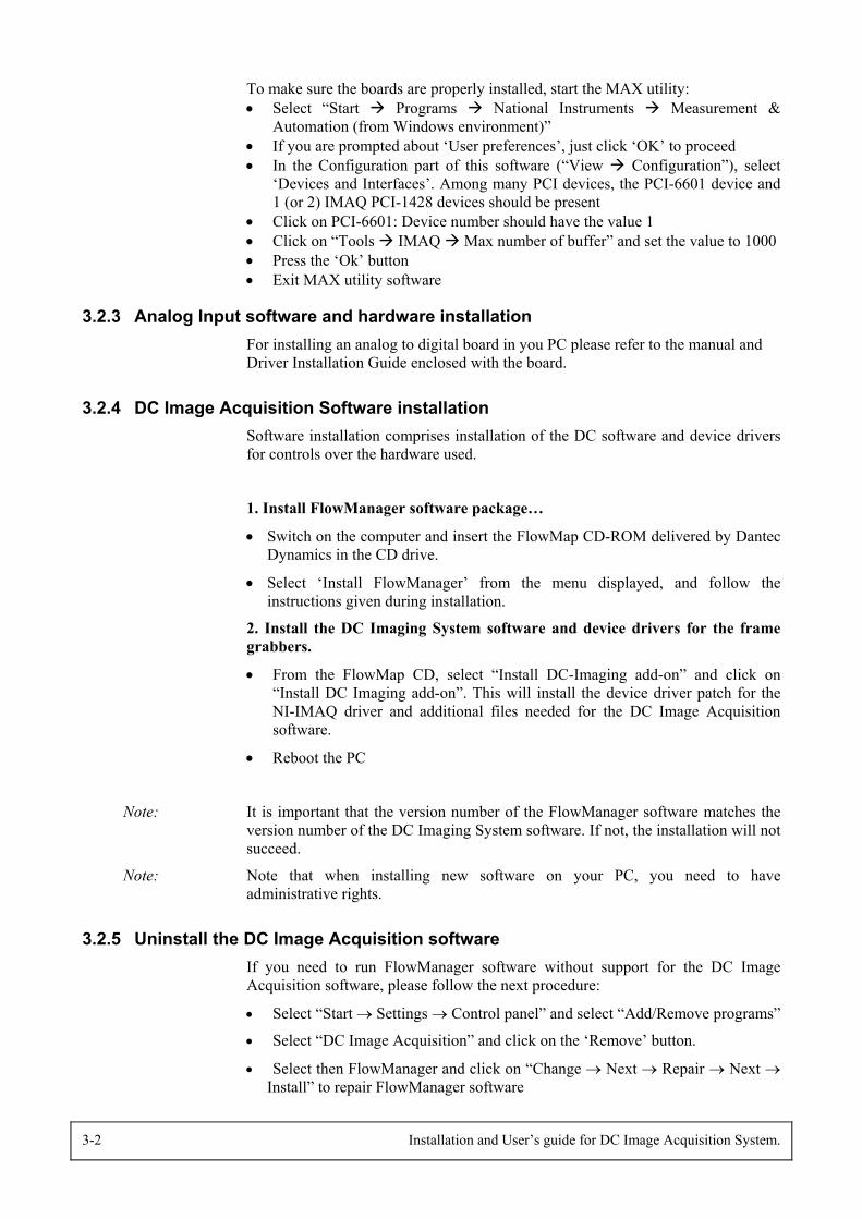
To make sure the boards are properly installed, start the MAX utility: • Select “Start Programs National Instruments Measurement &
Automation (from Windows environment)”• If you are prompted about ‘User preferences’, just click ‘OK’ to proceed• In the Configuration part of this software (“View Configuration”), select
‘Devices and Interfaces’. Among many PCI devices, the PCI-6601 device and1 (or 2) IMAQ PCI-1428 devices should be present
• Click on PCI-6601: Device number should have the value 1• Click on “Tools IMAQ Max number of buffer” and set the value to 1000• Press the ‘Ok’ button• Exit MAX utility software
3.2.3 Analog Input software and hardware installationFor installing an analog to digital board in you PC please refer to the manual andDriver Installation Guide enclosed with the board.
3.2.4 DC Image Acquisition Software installationSoftware installation comprises installation of the DC software and device driversfor controls over the hardware used.
1. Install FlowManager software package…
• Switch on the computer and insert the FlowMap CD-ROM delivered by DantecDynamics in the CD drive.
• Select ‘Install FlowManager’ from the menu displayed, and follow theinstructions given during installation.
2. Install the DC Imaging System software and device drivers for the framegrabbers.
• From the FlowMap CD, select “Install DC-Imaging add-on” and click on“Install DC Imaging add-on”. This will install the device driver patch for theNI-IMAQ driver and additional files needed for the DC Image Acquisitionsoftware.
• Reboot the PC
Note: It is important that the version number of the FlowManager software matches theversion number of the DC Imaging System software. If not, the installation will notsucceed.
Note: Note that when installing new software on your PC, you need to haveadministrative rights.
3.2.5 Uninstall the DC Image Acquisition softwareIf you need to run FlowManager software without support for the DC ImageAcquisition software, please follow the next procedure:
• Select “Start → Settings → Control panel” and select “Add/Remove programs”
• Select “DC Image Acquisition” and click on the ‘Remove’ button.
• Select then FlowManager and click on “Change → Next → Repair → Next →Install” to repair FlowManager software

Installation and User’s guide for DC Image Acquisition System. 3-3
Now the DC part has been removed and FlowManager will operate as in theoriginal installation.
3.3 Connections
3.3.1 Steps by steps procedureBefore utilisation of the DC system, all parts must be properly connected.
• Always turn off the power of the PC while hardware connections are made.
• On all cameras there is a DIP-switch. For the HiSense MKII/4M camera, verifythat all four pins are in the lower position (i.e. ‘off’ position). For theFlowSense camera, all pins must be in the left position.
• Connect the camera Digital I/O connector to the frame grabber Camera linkconnector using the 10 meter data cable. The other connector on the framegrabber is not used.
• Connect the synchronisation board to the Timer Box using the 1m interfacecable.
• Timer / laser box / camera(s) connections
- Connect the connector marked ‘Out1’ on the Timer Box to the Camera TimingI/O connector (HiSense MKII or 4M) or DC In/Trig (FlowSense) using the 10m trigger cable. If two cameras should be connected, use a BNC T-piece toconnect both cameras to the Timer Box ‘Out1’ connector.
- Using the 10 m long BNC cables, link the laser Flashlamp and Q-switchconnectors to the timer box as follows:
Connection on Timer box Laser cables
Out2 Fire flashlamp 1
Out 3 Fire flashlamp 2
Out 4 (For shutter option)
Out 5 Fire Q-switch 1
Out 6 Fire Q-switch 2
Out 7 Not used
Out 8 Not used
In 1 Trigger input
In 2 Not used
Figure 3-1: Connecting the interface cables to the Timer box
• Connect the camera power supply(ies) to the camera power connector(s) and tothe 220/110V supply.
• Turn on the power for the camera(s) and the PC
3-4 Installation and User’s guide for DC Image Acquisition System.
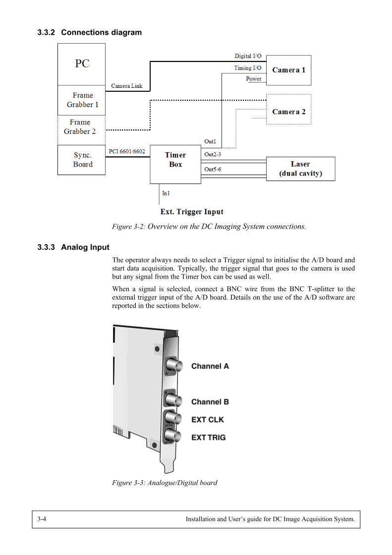
3.3.2 Connections diagram
Figure 3-2: Overview on the DC Imaging System connections.
3.3.3 Analog Input The operator always needs to select a Trigger signal to initialise the A/D board andstart data acquisition. Typically, the trigger signal that goes to the camera is usedbut any signal from the Timer box can be used as well.
When a signal is selected, connect a BNC wire from the BNC T-splitter to theexternal trigger input of the A/D board. Details on the use of the A/D software arereported in the sections below.
Figure 3-3: Analogue/Digital board
Installation and User’s guide for DC Image Acquisition System. 4-1
4. Using the DC Image Acquisition software4.1 First time use
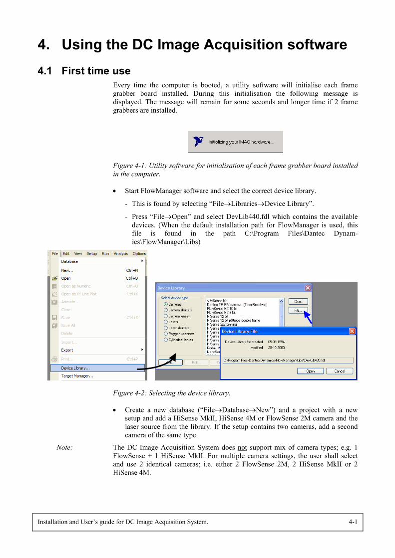
Every time the computer is booted, a utility software will initialise each framegrabber board installed. During this initialisation the following message isdisplayed. The message will remain for some seconds and longer time if 2 framegrabbers are installed.
Figure 4-1: Utility software for initialisation of each frame grabber board installedin the computer.
• Start FlowManager software and select the correct device library.
- This is found by selecting “File→Libraries→Device Library”.
- Press “File→Open” and select DevLib440.fdl which contains the availabledevices. (When the default installation path for FlowManager is used, thisfile is found in the path C:\Program Files\Dantec Dynam-ics\FlowManager\Libs)
Figure 4-2: Selecting the device library.
• Create a new database (“File→Database→New”) and a project with a newsetup and add a HiSense MkII, HiSense 4M or FlowSense 2M camera and thelaser source from the library. If the setup contains two cameras, add a secondcamera of the same type.
Note: The DC Image Acquisition System does not support mix of camera types; e.g. 1FlowSense + 1 HiSense MkII. For multiple camera settings, the user shall selectand use 2 identical cameras; i.e. either 2 FlowSense 2M, 2 HiSense MkII or 2HiSense 4M.
4-2 Installation and User’s guide for DC Image Acquisition System.
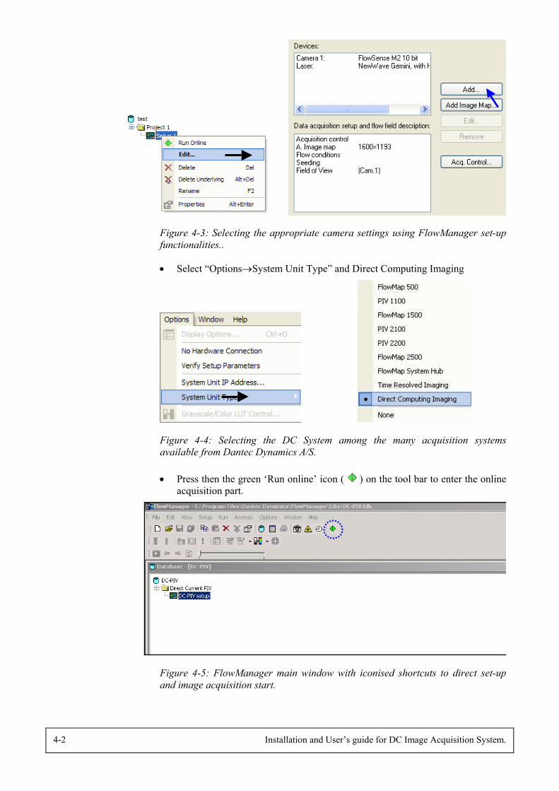
Figure 4-3: Selecting the appropriate camera settings using FlowManager set-upfunctionalities..
• Select “Options→System Unit Type” and Direct Computing Imaging
Figure 4-4: Selecting the DC System among the many acquisition systemsavailable from Dantec Dynamics A/S.
• Press then the green ‘Run online’ icon ( ) on the tool bar to enter the onlineacquisition part.
Figure 4-5: FlowManager main window with iconised shortcuts to direct set-upand image acquisition start.
Installation and User’s guide for DC Image Acquisition System. 4-3
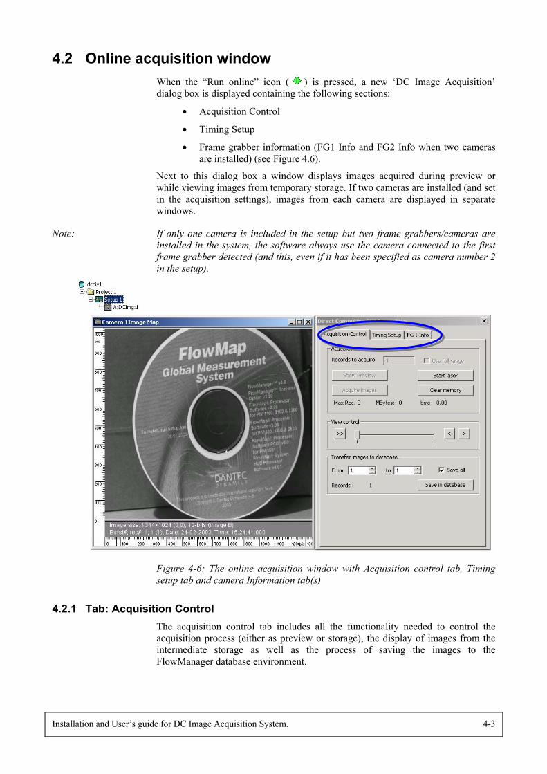
4.2 Online acquisition windowWhen the “Run online” icon ( ) is pressed, a new ‘DC Image Acquisition’dialog box is displayed containing the following sections:
• Acquisition Control
• Timing Setup
• Frame grabber information (FG1 Info and FG2 Info when two camerasare installed) (see Figure 4.6).
Next to this dialog box a window displays images acquired during preview orwhile viewing images from temporary storage. If two cameras are installed (and setin the acquisition settings), images from each camera are displayed in separatewindows.
Note: If only one camera is included in the setup but two frame grabbers/cameras areinstalled in the system, the software always use the camera connected to the firstframe grabber detected (and this, even if it has been specified as camera number 2in the setup).
Figure 4-6: The online acquisition window with Acquisition control tab, Timingsetup tab and camera Information tab(s)
4.2.1 Tab: Acquisition ControlThe acquisition control tab includes all the functionality needed to control theacquisition process (either as preview or storage), the display of images from theintermediate storage as well as the process of saving the images to theFlowManager database environment.

4-4 Installation and User’s guide for DC Image Acquisition System.
Note that the system memory in the PC is used as temporary storage for the imagesacquired. Therefore to make the acquisition process more efficient in terms ofmaximum number of images, the system memory must be prepared for the databefore the acquisition actually takes place. Also, depending on the amount ofimages to acquire this ‘initialisation process’ will take some time.
When the acquisition is started (by pressing the ‘Preview’ or ‘Initialise Acquire’button), a message is displayed informing about memory initialisation. Once done,the button ‘Begin’ is enabled and when pressed, the acquisition begins with thesettings described in the sections below.
Note: At the time of preparation, max. 90% of the available memory can be reserved fortemporary storage, while the remaining 10% are reserved for the operating system.
Image acquisition
Figure 4-7: Acquisition control tab / Acquisition parameters
• “Records to acquire“ & “Use full range”
To acquire a serie of images, specify the number of records to acquire or check theoption “Use full range” to record the maximum of records possible with the systemused. (Note that 1 record refers to a double image from each camera.) Also, thismaximum number of images is limited by the available memory in the PC. Belowthe “Initialize Acquire” button, a status line shows the storage capacity in terms ofmaximum records (and MBytes space). If the user enter say 250 records when thesystem only can store 150 images, the software automatically correct the valuetyped in the “Records to acquired” dialog and replaces it by the maximumavailable.
Additionally, the total time the acquisition will take (in seconds) is given. Thelatter depends on the trigger frequency when the ‘Internal master clock’ triggeringmode is used, and it is set to zero when the ‘External sync.’ mode is used (since thetrigger frequency is not known.)
• “Start laser” button
Pressing the “Start laser” button immediately starts the laser, which flashes at theTrigger frequency specified in the “Tab: Timing setup”. (Note that this is also away to get the laser stabilised before record acquisition, which is a critical issuewhen e.g. running LIF experiments.)
When the trigger mode is set to ‘External sync.’, the laser flashes each time theexternal trigger signal is received by the timer box.
Installation and User’s guide for DC Image Acquisition System. 4-5
Note: In any synchronisation case, no images are recorded until the “Show preview” orthe “Initialize Acquire” buttons are pressed.
• “Show preview” button
The “Show preview” button offers the possobility to acquire images without savingthe data in the memory. This is useful to ensure the system is set up properly forthe wanted acquisition or for the focusing of camera(s) prior to image acquisition.Press the “Stop Acquisition” button to stop the continuous preview.
Note: When the “Show preview” button is pressed, the system memory is initialised andthe synchronisation board runs on triggering the camera at the rate specified in thetiming setup (i.e. fixed rate or externally triggered). The software transfers eachdouble image from the camera(s) and display it in the image map window. At hightrigger frequencies (i.e. approx. 2-3Hz for 1 camera system and approx. 1-2Hz for2 cameras systems), overlap of images during updating the window may occur.This cosmetic display problem depends on the processing power of the PC anddoes not indicate at all technical problems with the image acquisition itself.
• “Initialize & Acquire” button
Once the number of images (and timing setup – see next section) are specified,acquisition can be done.
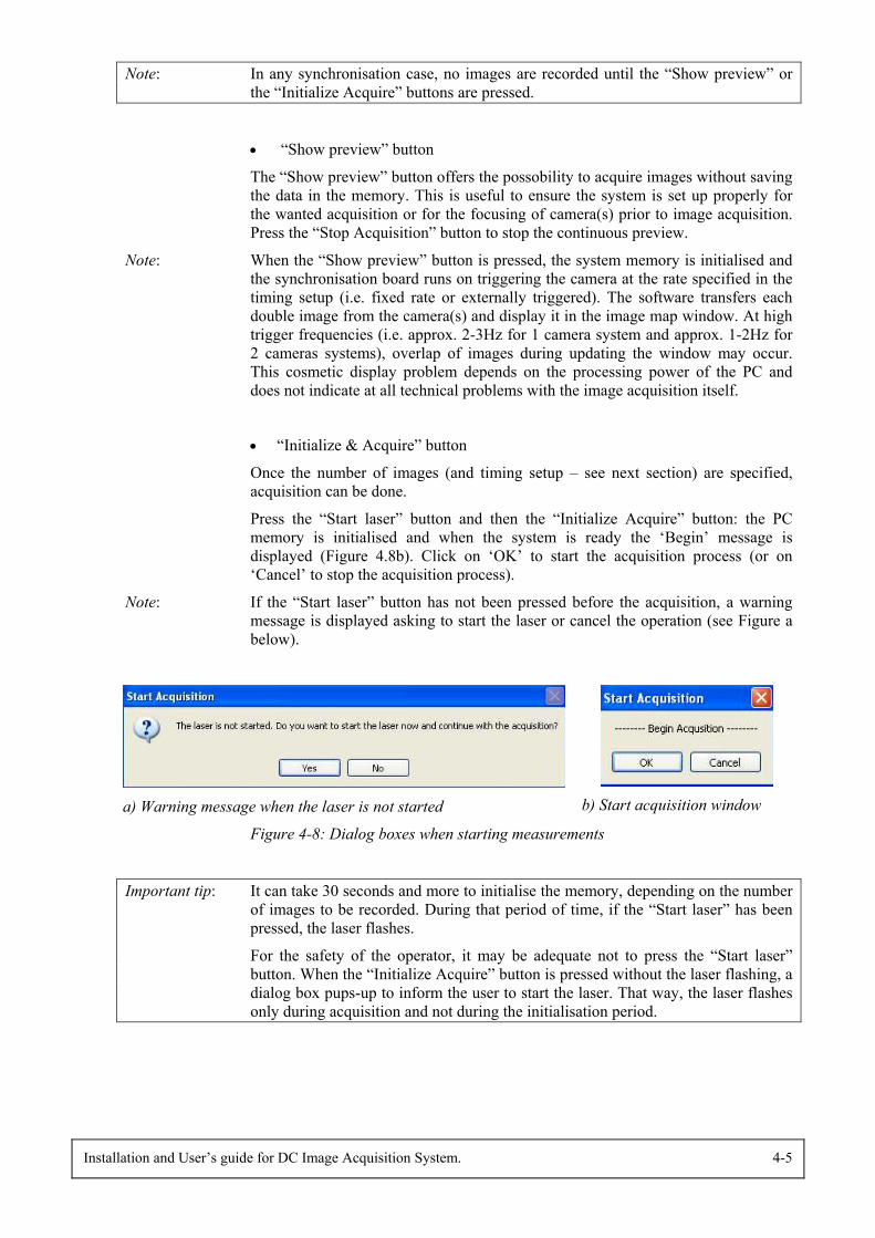
Press the “Start laser” button and then the “Initialize Acquire” button: the PCmemory is initialised and when the system is ready the ‘Begin’ message isdisplayed (Figure 4.8b). Click on ‘OK’ to start the acquisition process (or on‘Cancel’ to stop the acquisition process).
Note: If the “Start laser” button has not been pressed before the acquisition, a warningmessage is displayed asking to start the laser or cancel the operation (see Figure abelow).
a) Warning message when the laser is not started b) Start acquisition window
Figure 4-8: Dialog boxes when starting measurements
Important tip: It can take 30 seconds and more to initialise the memory, depending on the numberof images to be recorded. During that period of time, if the “Start laser” has beenpressed, the laser flashes.
For the safety of the operator, it may be adequate not to press the “Start laser”button. When the “Initialize Acquire” button is pressed without the laser flashing, adialog box pups-up to inform the user to start the laser. That way, the laser flashesonly during acquisition and not during the initialisation period.
4-6 Installation and User’s guide for DC Image Acquisition System.
The ‘Acquire images’ button now changes text and functionality to a ‘StopAcquisition’ button. Acquisition will run until the specified number of images toacquire is reached or when the user presses the ‘Stop Acquisition’ button. Note thatduring the acquisition, a status line shows the progress and time left to finishacquistion process.
When the acquisition has ended, the records are stored temporarily in to the PCmemory until the “Clear memory” button is pressed or on return to the mainFlowManager software for the processing of the images.
• “Clear memory “ button
This button is only enabled when at least 1 record is stored in the memory of thePC. When pressing this “Clear memory” button, all the data are removed from thetemporary storage, which frees the memory to another complete range of recordsacquisition. This button must therefore be pressed when acquiring a new set ofimages; i.e. after a set of records is saved to the FlowManager database, or whenthe user is not content of the quality of the images recorded and thereby wishes torun a new acquisition, keeping the settings as defined.
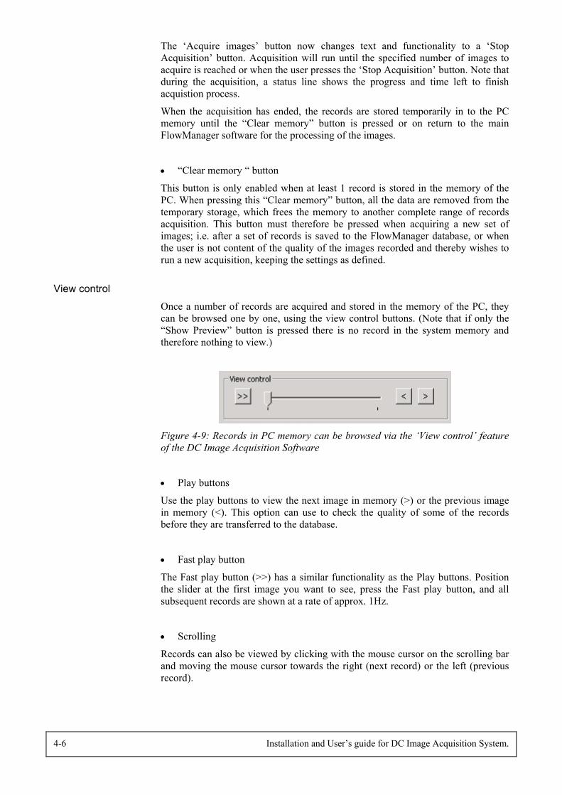
View control
Once a number of records are acquired and stored in the memory of the PC, theycan be browsed one by one, using the view control buttons. (Note that if only the“Show Preview” button is pressed there is no record in the system memory andtherefore nothing to view.)
Figure 4-9: Records in PC memory can be browsed via the ‘View control’ featureof the DC Image Acquisition Software
• Play buttons
Use the play buttons to view the next image in memory (>) or the previous imagein memory (<). This option can use to check the quality of some of the recordsbefore they are transferred to the database.
• Fast play button
The Fast play button (>>) has a similar functionality as the Play buttons. Positionthe slider at the first image you want to see, press the Fast play button, and allsubsequent records are shown at a rate of approx. 1Hz.
• Scrolling
Records can also be viewed by clicking with the mouse cursor on the scrolling barand moving the mouse cursor towards the right (next record) or the left (previousrecord).
Installation and User’s guide for DC Image Acquisition System. 4-7
Storage control
To save the images stored in the PC memory to FlowManager databaseenvironment, specify which images to save, using the ‘From’ and ‘To’ input fieldsor check the ‘Save all’. Press then the “Save in database” button, which will startthe transfer of the records selected from the system memory to the database and theharddisk. A status line will appear and show the progress and time left to finish thetransfer process. If needed, the user may stop this transfer by pressing the “Stoptransfer” button.
Figure 4-10: Storage control window.
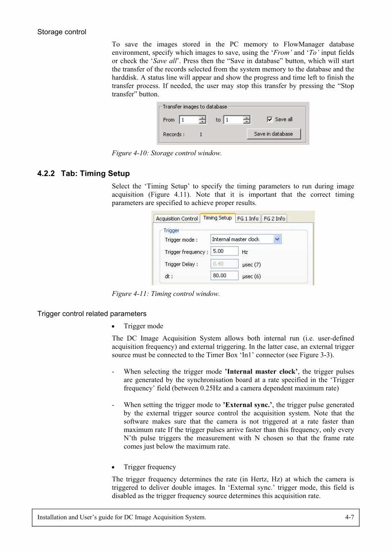
4.2.2 Tab: Timing SetupSelect the ‘Timing Setup’ to specify the timing parameters to run during imageacquisition (Figure 4.11). Note that it is important that the correct timingparameters are specified to achieve proper results.
Figure 4-11: Timing control window.
Trigger control related parameters
• Trigger mode
The DC Image Acquisition System allows both internal run (i.e. user-definedacquisition frequency) and external triggering. In the latter case, an external triggersource must be connected to the Timer Box ‘In1’ connector (see Figure 3-3).
- When selecting the trigger mode ’Internal master clock’, the trigger pulsesare generated by the synchronisation board at a rate specified in the ‘Triggerfrequency’ field (between 0.25Hz and a camera dependent maximum rate)
- When setting the trigger mode to ’External sync.’, the trigger pulse generatedby the external trigger source control the acquisition system. Note that thesoftware makes sure that the camera is not triggered at a rate faster thanmaximum rate If the trigger pulses arrive faster than this frequency, only everyN’th pulse triggers the measurement with N chosen so that the frame ratecomes just below the maximum rate.
• Trigger frequency
The trigger frequency determines the rate (in Hertz, Hz) at which the camera istriggered to deliver double images. In ‘External sync.’ trigger mode, this field isdisabled as the trigger frequency source determines this acquisition rate.
4-8 Installation and User’s guide for DC Image Acquisition System.
• Trigger delay
Note that this option is only available when the ‘External sync.’ trigger mode isselected. The ‘Trigger delay’ specifies the time necessary for the external triggerpulse to arrive so the laser fires (or the shutter is opened). Delays for the cameraand laser/shutter are also taken into consideration. Due to these delays in cameraand laser, the trigger delay must be above a minimum value. In case the specifiedvalue is below the minimum value, the software will automatically update thisvalue and display the adequate message.
Note: With the present DC Image Acquisition System, the maximum trigger delay is 4seconds.
• dt
The ‘dt’ is the time between the first and the second laser pulse. The first laserpulse is exposed in the first image (frame A) while the second laser pulse isexposed in the second image (frame B). The value of dt can vary in the range 5µsecto 80 msec. Naturally, the adequate value of ‘dt’ depends on the flow measured andcamera set-up. Prior knowledge of expected velocities is typically very helpful.
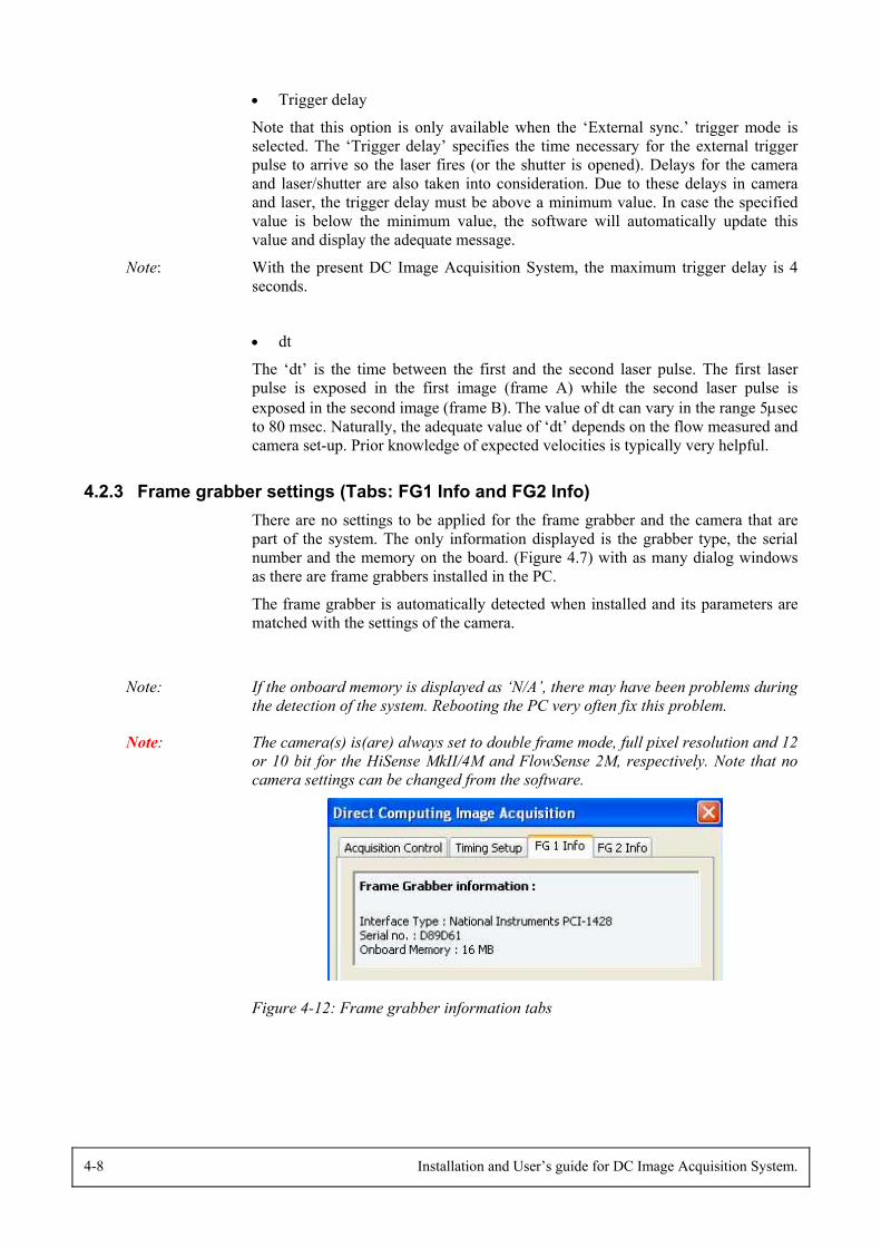
4.2.3 Frame grabber settings (Tabs: FG1 Info and FG2 Info)There are no settings to be applied for the frame grabber and the camera that arepart of the system. The only information displayed is the grabber type, the serialnumber and the memory on the board. (Figure 4.7) with as many dialog windowsas there are frame grabbers installed in the PC.
The frame grabber is automatically detected when installed and its parameters arematched with the settings of the camera.
Note: If the onboard memory is displayed as ‘N/A’, there may have been problems duringthe detection of the system. Rebooting the PC very often fix this problem.
Note: The camera(s) is(are) always set to double frame mode, full pixel resolution and 12or 10 bit for the HiSense MkII/4M and FlowSense 2M, respectively. Note that nocamera settings can be changed from the software.
Figure 4-12: Frame grabber information tabs
Installation and User’s guide for DC Image Acquisition System. 4-9
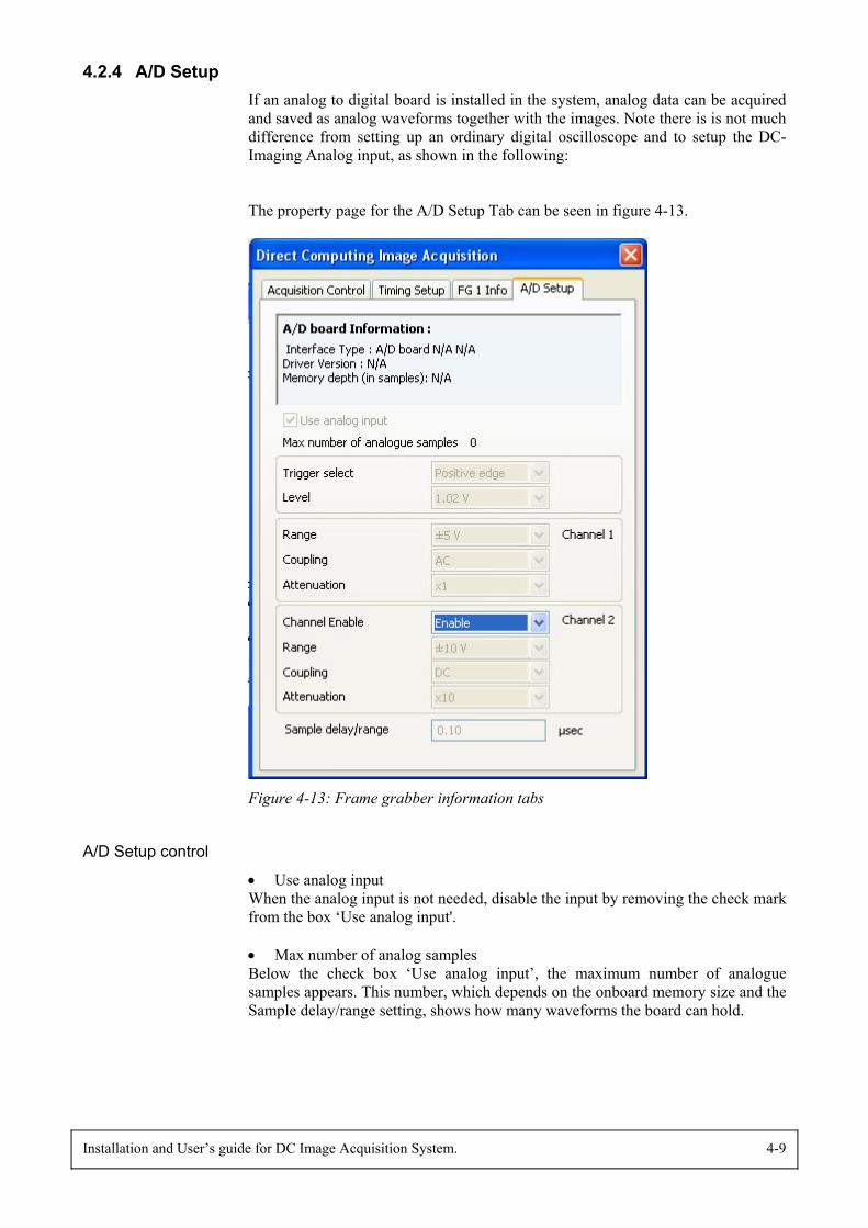
4.2.4 A/D SetupIf an analog to digital board is installed in the system, analog data can be acquiredand saved as analog waveforms together with the images. Note there is is not muchdifference from setting up an ordinary digital oscilloscope and to setup the DC-Imaging Analog input, as shown in the following:
The property page for the A/D Setup Tab can be seen in figure 4-13.
Figure 4-13: Frame grabber information tabs
A/D Setup control
• Use analog inputWhen the analog input is not needed, disable the input by removing the check markfrom the box ‘Use analog input'.
• Max number of analog samplesBelow the check box ‘Use analog input’, the maximum number of analoguesamples appears. This number, which depends on the onboard memory size and theSample delay/range setting, shows how many waveforms the board can hold.
4-10 Installation and User’s guide for DC Image Acquisition System.
When the user specifies a number of records that exceeds the max number ofanalog samples, only the first “max number of analog samples” will contain analogdata.
• Sample delay/range (in the bottom of the dialog)This input has two functions:1. The user specifies the delay from the trigger to the analog values that are saved
with image data.2. This setting specifies the length of the waveform in time. (The range is from
0.1 µs up to 1 ms.)
Trigger settings
• Trigger selectThe trigger input of the CompuScope board is ‘edge sensitive’. It is possible tospecify if it is a positive edge or a negative edge that triggers the acquisition.
• LevelTogether with specifying the trigger polarity a voltage must be specified. (Therange is from –5.0V to +5.0V.)
Channel 1 settings
• Range Specify here the input voltage range for channel A.
• CouplingThis input is used to specify if the input coupling is DC or AC. Like on an ordinaryoscilloscope, the user has the possibility to select or to remove any DC level offsetby choosing AC.
• AttenuationAttenuation is related to the probe that is used. If the operator uses a x10 probethen attenuation x10 must be used, likewise for a x100 probe the attenuation is setto x100. When no probe are used, just connect the BNC cable from the signalsource set the Attenuation to x1.
Channel 2 settings
• Channel EnableFor some boards it is possible to disable channel B.
• Range See Channel 1 settings.
• CouplingSee Channel 1 settings.
• AttenuationSee Channel 1 settings.
4.2.5 Fail-safe functionFor the safety of the user, a fail-safe function is included in the DC ImageAcquisition software.
Installation and User’s guide for DC Image Acquisition System. 4-11
To enable this safety system, the Timer box (which contains a watchdog circuit)must be connected to the laser interlock. The watchdog functions as a relay thatestablishes a connection between the two pins in the cable labelled ‘Interlock’when it is active. This circuit is always held active by the DC Image AcquisitionSoftware and if/when the software crashes or when leaving the online acquisitionsection of the software it “breaks” the connection
Important note: If the software crash ends by sending an error report, the safety connection will notopen until the user sends the report. Also if a ‘blue screen’ crash ends with memorydump, the connection will not open until the end of the dump.
Note: The cable from the ‘Laser’ connector on the Timer box, fits into the ‘Interlock’connector of e.g. the New Wave Solo PIV laser provided with the DC ImageAcquisition System. You can check that by entering the online acquisition part.The interlock then opens and it stays open until you return to the FlowManagermain part again. If this is not the case, check that the connection between the Timerbox and the laser interlock control is established.
Note: During the memory preparation, occasional closing and opening of the interlock may occur.


Installation and User’s guide for DC Image Acquisition System. 5-1
5. TroubleshootingProblem: The very first time images are acquired after the camera is powered on,the frames A and B may be switched.
Solution: Stop the acquisition/preview, and the image sequence will be correct inthe following acquisitions.
Problem: A timeout error is received
Solution: Turn off the power for the camera, and on again.
Problem: When using trigger mode External sync., the first image received may beexposed at a wrong moment (before or after the laser pulse)
Solution: If possible, begin the acquisition before the external trigger source isactivated.
Problem: If you cannot select the DC System in the the emnu “Options→SystemUnit Type, it may be due to conflicts between the installed drivers and old driversof the NI-IMAQ or NI-DAQ type.
Solution: Uninstall the DC software, the NI-DAQ driver and the NI-IMAQ driver.Repair the FlowManager software and install the DC Image Acquisition softwareand the NI_DAQ driver again.
Problem: You cannot change settings in the timing setup even if no data belong tothe current setup.
Solution: Exit the online acquisition part and enter again. It can be because youhave deleted images, which belong to the currrent setup while you were in theonline acquisition part.
Problem: No image on either frame A or frame B
Solution: Check the cable connecting the Timer Box and the synchronisation boardin the PC.

Installation and User’s guide for DC Image Acquisition System. 6-1
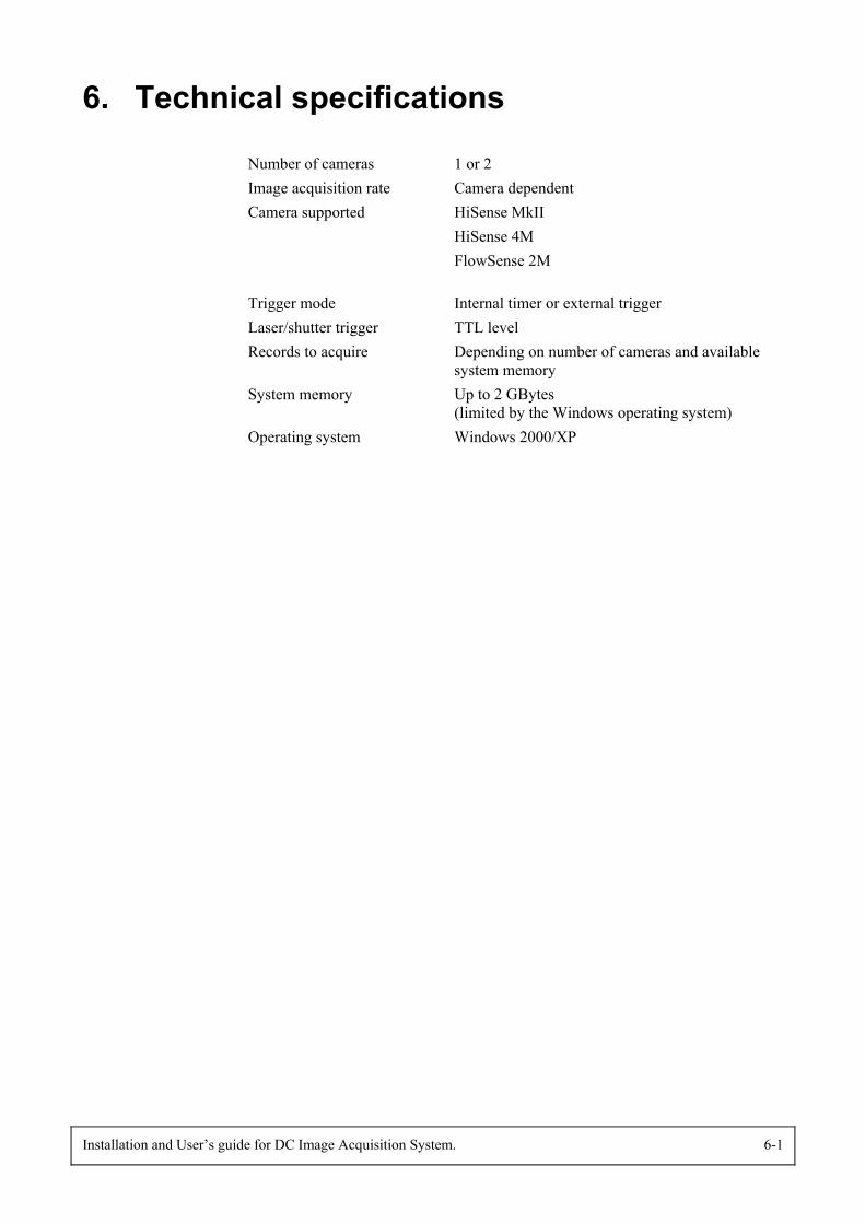
6. Technical specifications
Number of cameras 1 or 2Image acquisition rate Camera dependentCamera supported HiSense MkII
HiSense 4MFlowSense 2M
Trigger mode Internal timer or external triggerLaser/shutter trigger TTL levelRecords to acquire Depending on number of cameras and available
system memorySystem memory Up to 2 GBytes
(limited by the Windows operating system)Operating system Windows 2000/XP