Embed Size (px)
Citation preview

Sonavision Ltd. Aberdeen, Scotland
Issue 2 5249-31-0014 Page 1 of 30
OPERATION AND INSTALLATION MANUAL
DETAILS OF THE EQUIPMENT
PART NUMBER: 5249-32-0001
DESCRIPTION: ROXANN INSTALLATION MANUAL
APPROVALS ORIGINATOR: R.J HARDIE
ENGINEER:
PRODUCTION: R.J HARDIE
ISS DATE DESCRIPTION BY CHK
0 DRAFT FOR APPROVAL
1 RELEASE FOR PRODUCTION
2 30/03/10 UPGRADE TO NEW DOCUMENTATION RH

Sonavision Ltd. Aberdeen, Scotland
Issue 2 5249-31-0014 Page 2 of 30
3
4
5
The latest issue of this document is held in electronic form. This is available from our website www.sonavision.co.uk
COPYRIGHT © SONAVISION LIMITED AUGUST 2008 The copyright in this document is the property of Sonavision Limited. The
document is supplied by Sonavision Limited on the express terms that it may
not be copied, used, or disclosed to others except as authorised in writing by
Sonavision Limited. Sonavision Limited reserves the right to change, modify
and update designs and specifications as part of their ongoing product
development programme.
TECHNICAL SUPPORT
Address
Sonavision Limited Unit 12 Energy Development Centre Aberdeen Science and Energy Park Bridge of Don Aberdeen AB23 8GD Scotland
Telephone +44 (0)1224 707737
Fax +44 (0)1224 827290
Email [email protected]
Website www.sonavision.co.uk

Sonavision Ltd. Aberdeen, Scotland
Issue 2 5249-31-0014 Page 3 of 30
MAINTENANCE AND WARRANTY POLICY
Sonavision Limited warrants that its products are free from defects at the time of
delivery and subject to the conditions listed below, undertakes to repair, or at its
option replace, any product found to be defective in material or workmanship within
one year after delivery, whichever is less, to the original purchaser by Sonavision
Limited or its authorised representative.
CONDITIONS Sonavision Limited must be immediately notified of any suspected defect and if advised by Sonavision Limited, the equipment subject to defect shall be returned to Sonavision Limited, freight prepaid. This warranty does not cover defects which are caused as a result of improper usage, repair, maintenance, alteration or installation unless such activities have been undertaken by Sonavision Limited or its authorised representative. On completion of any warranty work, Sonavision Limited will return the equipment,
freight prepaid.
Sonavision Limited retains the sole right to accept or reject any warranty claim.
SAFETY AND ENVIRONMENTAL STATEMENT
Lethal voltages are exposed within the control unit when the top cover is removed. The unit should always be disconnected from the mains supply before removing or operating any internal components. The unit should be earthed at all times. The unit contains electrostatically sensitive devices (ESSD). Appropriate static protection should be used when handling subassemblies.
RELATED DOCUMENTS
Document Number Document Title

Sonavision Ltd. Aberdeen, Scotland
Issue 2 5249-31-0014 Page 4 of 30
RoxAnn™ Installation Manual Survey / Fishing Version RoxAnn™ is designed and manufactured by Sonavision Ltd. of Aberdeen, Scotland. Sonavision reserves the right to alter the specification of the RoxAnn™ System and the manual will be updated accordingly. RoxAnn™ has extensive patent protection which includes: U.S. Patent numbers 4648081 & 4777630 & European and Asian Patents. Sonavision Ltd., 16 Denmore Industrial Estate, Denmore Road, Bridge of Don, Aberdeen, Scotland AB23 8JW Tel: + 44 (0)1224 707737 Fax: + 44 (0)1224 827290 Email: [email protected] Website: www.sonavision.co.uk © Sonavision Ltd. 2004
Sonavision Ltd. Aberdeen, Scotland
Issue 2 5249-31-0014 Page 5 of 30
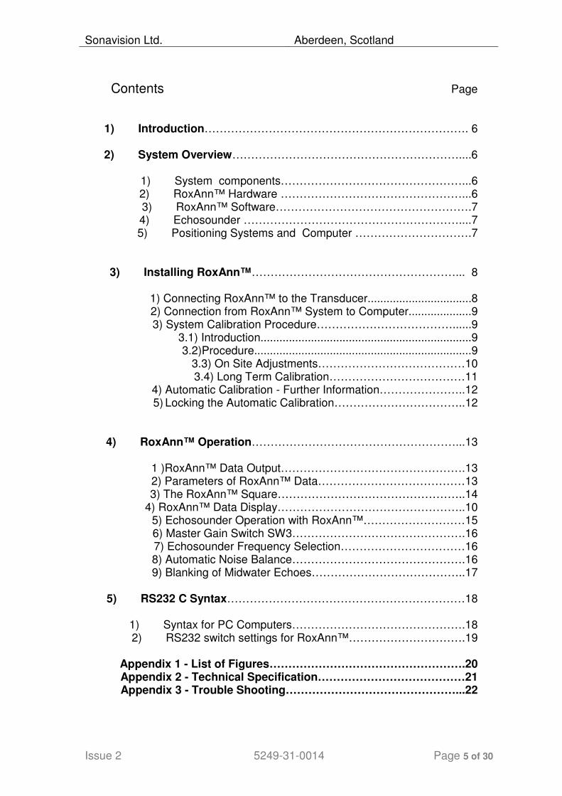
Contents Page
1) Introduction……………………………………………………………. 6
2) System Overview……………………………………………………....6
1) System components…………………………………………...6 2) RoxAnn™ Hardware …………………………………………...6 3) RoxAnn™ Software…………………………………………….7 4) Echosounder …………………………………………………....7 5) Positioning Systems and Computer ………………………….7
3) Installing RoxAnn™………………………………………………... 8
1) Connecting RoxAnn™ to the Transducer.................................8 2) Connection from RoxAnn™ System to Computer....................9 3) System Calibration Procedure………………………………......9
3.1) Introduction...................................................................9 3.2)Procedure.....................................................................9
3.3) On Site Adjustments…………………………………10 3.4) Long Term Calibration………………………………11
4) Automatic Calibration - Further Information…………………..12 5) Locking the Automatic Calibration……………………………..12
4) RoxAnn™ Operation………………………………………………...13
1 )RoxAnn™ Data Output………………………………………….13 2) Parameters of RoxAnn™ Data…………………………………13 3) The RoxAnn™ Square…………………………………………..14
4) RoxAnn™ Data Display…………………………………………..10 5) Echosounder Operation with RoxAnn™………………………15 6) Master Gain Switch SW3……………………………………….16 7) Echosounder Frequency Selection……………………………16 8) Automatic Noise Balance……………………………………….16 9) Blanking of Midwater Echoes…………………………………..17
5) RS232 C Syntax………………………………………………………18
1) Syntax for PC Computers……………………………………….18 2) RS232 switch settings for RoxAnn™………………………….19
Appendix 1 - List of Figures…………………………………………….20 Appendix 2 - Technical Specification…………………………………21 Appendix 3 - Trouble Shooting………………………………………...22

Sonavision Ltd. Aberdeen, Scotland
Issue 2 5249-31-0014 Page 6 of 30
1. Introduction Thank you for your commitment to RoxAnn, a product of Sonavisions many years of experience in the design of hydro-acoustic processing equipment. This manual is designed to take you through the basic features of the RoxAnn unit and to demonstrate the installation process. Once installed and calibrated, the RoxAnn unit can be used as a fully automatic sensor of seabed data with minimal need for operational support. RoxAnn can be effectively deployed in any situation where the nature of the seabed is being investigated. It can be used to acquire precise seabed identification data for hydrography, oil rig site surveying, pipe and cable laying, environmental surveys and for fisheries research. Incorporation of calibration and noise balancing circuitry has simplified the installation procedure for RoxAnn. You will be able to commission your RoxAnn unit, tuned to your particular echo sounder, by following the straightforward instructions outlined in the installation section (Section 3). There is no requirement for specialised tools or skills, only a short trip to waters of a specified depth in which to activate RoxAnn automatic calibration circuitry (Section 3.5). Similarly, for operational procedures, our manual is brief and generally non-technical. There are no user adjustments particular to routine RoxAnn deployment. Manipulation and display of RoxAnn data is by means of a RoxAnn specific plotter program. RoxAnn processes physical phenomena inherent in the echo sounder return signals, which have hitherto remained unexploited. Sonavision has also designed a suite of powerful and flexible data analysis and display software for RoxAnn seabed information: RoxMap, RoxMap-3D or RoxMap Scientific. With RoxAnn you may "open a window" to the seabed and realise new capabilities in the study of events at "the bottom". We wish you every success and plain sailing with your RoxAnn operations. 2. System Overview 2.1. System Components For routine RoxAnn deployment a system is configured comprising: Echosounder RoxAnn hardware Computer RoxAnn compatible software program Positioning system (e.g. DGPS)

Sonavision Ltd. Aberdeen, Scotland
Issue 2 5249-31-0014 Page 7 of 30
2.2. RoxAnn Hardware RoxAnn hardware includes a fully automatic "Black Box" processor and a head amplifier unit. The RoxAnn head amplifier unit allows easy interface with most known echosounders by direct connection across the main transducer terminals (See Fig.1). A specific system configuration for the Atlas Elektronik "AE" DESO range of echosounders is also possible (Fig.2). Thus the RoxAnn hardware components are as follows: • A head amplifier which connects directly to the echosounder transducer (in parallel with the echosounder) and is matched for the echosounder transmitter output circuitry such that it has a negligible effect on the performance of the transceiver. • A parallel receiver which accepts the reflected echoes from the head amplifier and applies accurate signal processing, especially of time varied gain and filtering. Gating of the signal and integration of the first and second echoes is performed within this unit. • Optional RoxAnn interface box is a junction box which is fitted with connectors for easy connection of the head amplifier unit to Odom, Simrad and Atlas Elektronik echosounders. The dimensions of the RoxAnn hardware components are shown in Fig. 4 and the maximum recommended cabling lengths are identified and specified in Fig. 5. 2.3. RoxAnn Software Interaction with RoxAnn is typically via RoxAnn compatible hydrographic or "plotting" software installed in the computer. A considerable range of functions are available for the manipulation of numerical RoxAnn data. RoxAnn compatibility is now a common feature of a number of proprietary software programs for navigational and hydrographic uses. Sonavision supply a plotter package specifically designed to make the best of the RoxAnn data. This package is called RoxMap. 2.4. Echosounder RoxAnn can be supplied suitable for operation with virtually all known makes of echosounders. Each RoxAnn unit will be supplied from the workshop to operate at the specific frequency indicated by the customer for the host echosounder. 2.5. Positioning System and Computer

Sonavision Ltd. Aberdeen, Scotland
Issue 2 5249-31-0014 Page 8 of 30
Specific system compatibility for the computer and positioning system will depend on the requirements and interface capabilities of the software program mentioned in Section 2.3. 3. Installing RoxAnn Please check that there is no evidence of mishandling of your RoxAnn unit in transit or any indication of possible damage. Before making any connections, ensure that the echosounder and computer are switched off. High voltages exist at the transducer terminals and may damage the equipment if it is live during the installation process. Ensure that the RoxAnn head amplifier is the correct frequency for the echosounder selected. Check the recommended cabling lengths in Fig. 5 and make sure all cable runs are not more than the maximum specified.
Sonavision Ltd. Aberdeen, Scotland
Issue 2 5249-31-0014 Page 9 of 30
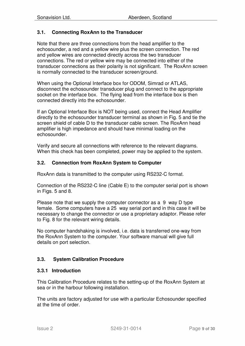
3.1. Connecting RoxAnn to the Transducer Note that there are three connections from the head amplifier to the echosounder, a red and a yellow wire plus the screen connection. The red and yellow wires are connected directly across the two transducer connections. The red or yellow wire may be connected into either of the transducer connections as their polarity is not significant. The RoxAnn screen is normally connected to the transducer screen/ground. When using the Optional Interface box for ODOM, Simrad or ATLAS, disconnect the echosounder transducer plug and connect to the appropriate socket on the interface box. The flying lead from the interface box is then connected directly into the echosounder. If an Optional Interface Box is NOT being used, connect the Head Amplifier directly to the echosounder transducer terminal as shown in Fig. 5 and tie the screen shield of cable D to the transducer cable screen. The RoxAnn head amplifier is high impedance and should have minimal loading on the echosounder. Verify and secure all connections with reference to the relevant diagrams. When this check has been completed, power may be applied to the system. 3.2. Connection from RoxAnn System to Computer RoxAnn data is transmitted to the computer using RS232-C format. Connection of the RS232-C line (Cable E) to the computer serial port is shown in Figs. 5 and 8. Please note that we supply the computer connector as a 9 way D type female. Some computers have a 25 way serial port and in this case it will be necessary to change the connector or use a proprietary adaptor. Please refer to Fig. 8 for the relevant wiring details. No computer handshaking is involved, i.e. data is transferred one-way from the RoxAnn System to the computer. Your software manual will give full details on port selection. 3.3. System Calibration Procedure 3.3.1 Introduction This Calibration Procedure relates to the setting-up of the RoxAnn System at sea or in the harbour following installation. The units are factory adjusted for use with a particular Echosounder specified at the time of order.

Sonavision Ltd. Aberdeen, Scotland
Issue 2 5249-31-0014 Page 10 of 30
The unit does, however, require an initial calibration to adjust to the specific characteristics of the echosounder and its transducer. This feature is operated by means of the RED button on the rear panel. It is important that calibration is carried out over known seabed conditions in a specific range of water depths. The type of seabed required for calibration of the system depends on the frequency of operation. We recommend a sandy bottom in a water depth of 30 to 50 metres for low frequency systems and harbour mud at 4 to 5 metres depth for 200 kHz systems. 3.3.2 Procedure Switch the GAIN CONTROL (SW3) on the rear panel to “0” position (minimum gain). Go to an area of seabed which is known to be as defined above for the actual system. Press the RED button on the rear panel. The effect of the calibration will depend upon the type of software displaying the

Sonavision Ltd. Aberdeen, Scotland
Issue 2 5249-31-0014 Page 11 of 30
RoxAnn information. If a precalibrated RoxAnn box is in use then readings on the display should now tie in with the type of seabed present. If a precalibrated box is not available then the readings can be used to generate a box using ground truthing or sampling of some form. 3.3.3 On Site Adjustments The above procedure achieves the optimum calibration for most work. If it is found, during site work, that the crosses are clustered in one area too close to either the top right or bottom left of the box for many different seabed types then the gain can be adjusted manually. This will result in a loss of absolute calibration so it should be carried out with caution. The manual gain control will move the area plotted for a specific seabed in a diagonal from the bottom left to top right of the screen (approximately). Increasing the gain will move the plots to the right. Since the original calibration was carried out with a gain setting of zero, the gain can only be increased if the RED button is again pressed. If a gain reduction is required then the best way to proceed is to set the manual gain switch to a midrange position of “5” and then press the RED button again. The manual gain control can now be adjusted up or down to place the plotted crosses in a suitable area of the RoxAnn box. Remember, however, that absolute calibration will no longer be valid. In some situations, typically in bad weather, the RoxAnn unit may recognise a fish shoal or aeration under the hull as a first seabed echo and therefore produce incorrect results. The RoxAnn Survey Unit is provided with a range of plug-in components which allow the blanking pulse to be extended to eliminate these false echoes in the water column. See section 4.9 for further details. Care must be taken to avoid blanking out the first seabed return since this will invalidate the RoxAnn data.
Sonavision Ltd. Aberdeen, Scotland
Issue 2 5249-31-0014 Page 12 of 30
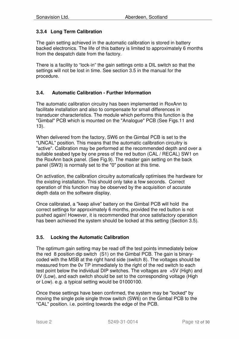
3.3.4 Long Term Calibration The gain setting achieved in the automatic calibration is stored in battery backed electronics. The life of this battery is limited to approximately 6 months from the despatch date from the factory. There is a facility to “lock-in” the gain settings onto a DIL switch so that the settings will not be lost in time. See section 3.5 in the manual for the procedure. 3.4. Automatic Calibration - Further Information The automatic calibration circuitry has been implemented in RoxAnn to facilitate installation and also to compensate for small differences in transducer characteristics. The module which performs this function is the "Gimbal" PCB which is mounted on the "Analogue" PCB (See Figs.11 and 13). When delivered from the factory, SW6 on the Gimbal PCB is set to the "UNCAL" position. This means that the automatic calibration circuitry is "active". Calibration may be performed at the recommended depth and over a suitable seabed type by one press of the red button (CAL / RECAL) SW1 on the RoxAnn back panel. (See Fig.9). The master gain setting on the back panel (SW3) is normally set to the "0" position at this time. On activation, the calibration circuitry automatically optimises the hardware for the existing installation. This should only take a few seconds. Correct operation of this function may be observed by the acquisition of accurate depth data on the software display. Once calibrated, a "keep alive" battery on the Gimbal PCB will hold the correct settings for approximately 6 months, provided the red button is not pushed again! However, it is recommended that once satisfactory operation has been achieved the system should be locked at this setting (Section 3.5). 3.5. Locking the Automatic Calibration The optimum gain setting may be read off the test points immediately below the red 8 position dip switch (S1) on the Gimbal PCB. The gain is binary-coded with the MSB at the right hand side (switch 8). The voltages should be measured from the 0v TP immediately to the right of the red switch to each test point below the individual DIP switches. The voltages are +5V (High) and 0V (Low), and each switch should be set to the corresponding voltage (High or Low). e.g. a typical setting would be 01000100. Once these settings have been confirmed, the system may be "locked" by moving the single pole single throw switch (SW6) on the Gimbal PCB to the "CAL" position. i.e. pointing towards the edge of the PCB.

Sonavision Ltd. Aberdeen, Scotland
Issue 2 5249-31-0014 Page 13 of 30
The system is now "locked". If this setting is to be retained for permanent use it is now only necessary to move the link from the J1 position to J2. This isolates the "keep alive" circuitry from the PCB i.e. switches to mains power. A great advantage of the S1 switching is that if the RoxAnn equipment is being used in different environments and with different echosounders or transducers, the corresponding optimum gain settings may be "dialled" back into the equipment. Once calibration has been completed, "fine-tuning" may be achieved by advancing the switch SW3 on the back panel (master gain) in a clockwise direction. However this switch is generally left in the minimum gain position (0), and this is the recommended position during the Automatic Calibration operation. You have now successfully installed RoxAnn and the unit is fully operational to supply data to the computer. Seabed data is now available to be displayed on your chosen software package. The software package may include test programs to check that RoxAnn is communicating correctly with the computer. Details of these test programmes will be contained in your software manual. 4. RoxAnn Operation RoxAnn signal processing is entirely automatic, consequently there is minimal requirement for operational support of the hardware processing unit. (The RoxAnn processor features no user controls). System integrity is indicated by two green LED lights mounted in the front panel. The user interface to RoxAnn data is via the RoxAnn compatible software program deployed. Typical features of RoxAnn compatible software include data storage, display, analysis, post-processing and data conversion for export to other programs. 4.1. RoxAnn Data Output RoxAnn data is streamed from the parallel receiver via RS 232-C, which may be connected directly to a computer for data acquisition/display. 4.2. Parameters of RoxAnn Data Three parameters are supplied by RoxAnn to the data acquisition system/computer: • E1 • E2

Sonavision Ltd. Aberdeen, Scotland
Issue 2 5249-31-0014 Page 14 of 30
• Depth data ( as two-way pulse travel time). E1 and E2 are independent DC voltage readings from 0 volts to a maximum of 4.095 Volts. E1 information is a parameter giving data on the topographical roughness or "texture" of the material on the surface of the sea/river bed. E2 information is a parameter supplying data on the relative hardness or acoustic impedance of the seabed. Depth data is given as a time in milliseconds, being the time from the host echosounder transmission to the acquisition of the first return seabed echo. This RoxAnn depth data is not intended to be used as a primary depth sensor but may be used as a backup to the primary echosounder depth digitiser. 4.3. The RoxAnn Square For display and analysis of E1, E2 data all RoxAnn compatible software programs include a mechanism referred to as the "RoxAnn Square". The Cartesian (x,y) display of the RoxAnn Square has been found to be a most effective means of displaying a combination of two independent variables. A single cursor moving in the square plotting field displays current E1 and E2 values. The cursor on screen is easily understood and thus the use of the RoxAnn Square has greatly facilitated the calibration of the instrument and classification of different seabed types. E1 data is normally displayed on the y axis of the RoxAnn Square while E2 is on the x axis. This combination of data gives a specific, repeatable and depth-corrected signature for particular seabed materials and specific seabed phenomena. A typical distribution of E1 and E2 values relating to seabed types is shown in Fig. 6. This shows a typical RoxAnn "boxfile" produced using automatic calibration with the Odom Echotrac echosounder at a frequency of 205 kHz. Transducer beam width is approximately 10 degrees. Note that the maximum voltages on both E1 and E2 axes in this boxfile are 0.5 volts. Thus, very simply, if the cursor in the RoxAnn Square is in the bottom left-hand corner, the material on the seabed is very soft and smooth, possibly mud. If it is positioned in the top right- hand corner, it is a very hard seabed type, e.g. bedrock. It will be readily appreciated that the infinite variety of seabed types will be characterised by many different combinations of roughness and hardness in E1 and E2 terms. 4.4. RoxAnn Data Display Using the RoxAnn Square, RoxAnn data may easily be colour-coded to distinguish sets of E1 and E2 values indicative of specific seabed types.

Sonavision Ltd. Aberdeen, Scotland
Issue 2 5249-31-0014 Page 15 of 30
Ground truthing using traditional tools, such as grabs and cameras may assist in the configuration of the colour-coding and analysis of data specific to any echosounder / transducer configuration used with RoxAnn. RoxAnn compatible software programs generally accept positional data in conjunction with RoxAnn values and are thus capable of charting RoxAnn colour-coded seabed information. By means of colour-coding of tracks in underway surveying, the charting of areas by RoxAnn parameters becomes fully automatic. The colour-coding of the RoxAnn values is a very powerful display function. However, RoxAnn data is invariably acquired and stored as raw E1 and E2 values and is suitable as reference data. By a manipulation of the RoxAnn Square in post-processing, features of current interest can be highlighted and analyses performed to reveal significant traits or changes. The variety of RoxAnn compatible software programs feature similar RoxAnn data handling functions. They differ in their general application, Sonavision can assist with your selection of computer hardware and software options, appropriate to your own requirements. 4.5. Echosounder Operation with RoxAnn RoxAnn data sets are specific to the characteristics of the echosounder and transducer deployed. Changes in the transmit signal from the echosounder will also require changes in the analysis of the RoxAnn data achieved. It is therefore important to either maintain a consistent output power from the echosounder or to distinguish data sets by the echosounder power setting used. Because RoxAnn is analysing very small changes in echo strength it is also important to attempt to keep the pulse width at a constant value for the duration of the survey. If the pulse width is widened there will be a proportionate increase of mean transmitted power into the water, and thus an increase in the relative strength of the return echoes. Reference to the echosounder manual together with an approximate knowledge of the deepest area to be surveyed will help in choosing a suitable echosounder range to fulfil the above requirements for the duration of the survey. Adjustments to the phasing of the echosounder display do not normally affect the characteristic of the transmit pulse. Since RoxAnn also utilises the second echo return or double echo, it is important that the depth range chosen for the echosounder allows RoxAnn to receive this second echo return before the next transmission. This does not mean that the second echo has to be visible on the paper printout or CRT display, only that the pulse rate frequency (PRF) is long enough to include this data.
Sonavision Ltd. Aberdeen, Scotland
Issue 2 5249-31-0014 Page 16 of 30
If this condition is not satisfied RoxAnn will stop processing until a suitable echosounder PRF is selected. 4.6. Master Gain: Switch SW3 This switch is situated on the back panel of the RoxAnn processor unit. It's function is to adjust the overall gain or sensitivity of RoxAnn. Other than it's limited use in the calibration phase there will not normally be any requirement to adjust this switch following the initial calibration of the processor unit as outlined in section 3.5. 4.7. Echosounder Frequency Selection Each RoxAnn unit is factory set for optimum performance at a user specified frequency. Ideally this frequency should also be the optimum frequency for seabed classification within the range of depths intended for the system. Sonavision can advise on the selection of suitable frequencies. RoxAnn is not designed to give sub-bottom information. However, in shallow water, provided the depth is reasonably constant, useful seabed data may be acquired when using low frequencies e.g. 24 or 33 kHz. Signal penetration may give rise to anomalous results under certain conditions, consequently we do not generally advise the operation of low frequency systems in shallow water. 4.8. Automatic Noise Balance Because of problems encountered due to high ambient acoustic/electrical noise within the marine laboratory/wheelhouse environment, Sonavision has designed special circuitry to reduce these effects. The operation is automatic, but is only capable of handling a maximum level of noise before the processed data becomes degraded. Two green LEDs are fitted immediately below the RoxAnn label on the front panel (see Fig.1). When the noise environment is acceptable, the two lamps glow with equal intensity. The higher the ambient noise, the dimmer the left LED will become. If this lamp extinguishes completely, a severe noise problem exists which must be corrected prior to data collection. e.g. check grounding of equipment within the proximity of RoxAnn etc. The LEDs are an excellent "QC" for RoxAnn. A high degree of confidence is appropriate when both lamps are evenly illuminated. Please pay particular attention to this QC facility when surveying at higher than normal vessel speeds and when RoxAnn is being deployed as portable equipment on vessels of convenience/opportunity. 4.9. Blanking of Midwater Echoes
Sonavision Ltd. Aberdeen, Scotland
Issue 2 5249-31-0014 Page 17 of 30
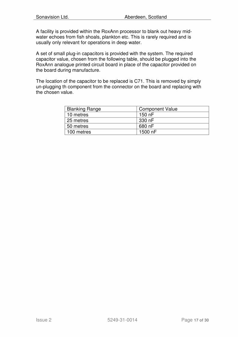
A facility is provided within the RoxAnn processor to blank out heavy mid-water echoes from fish shoals, plankton etc. This is rarely required and is usually only relevant for operations in deep water. A set of small plug-in capacitors is provided with the system. The required capacitor value, chosen from the following table, should be plugged into the RoxAnn analogue printed circuit board in place of the capacitor provided on the board during manufacture. The location of the capacitor to be replaced is C71. This is removed by simply un-plugging th component from the connector on the board and replacing with the chosen value.
Blanking Range Component Value 10 metres 150 nF 25 metres 330 nF
50 metres 680 nF 100 metres 1500 nF
Sonavision Ltd. Aberdeen, Scotland
Issue 2 5249-31-0014 Page 18 of 30
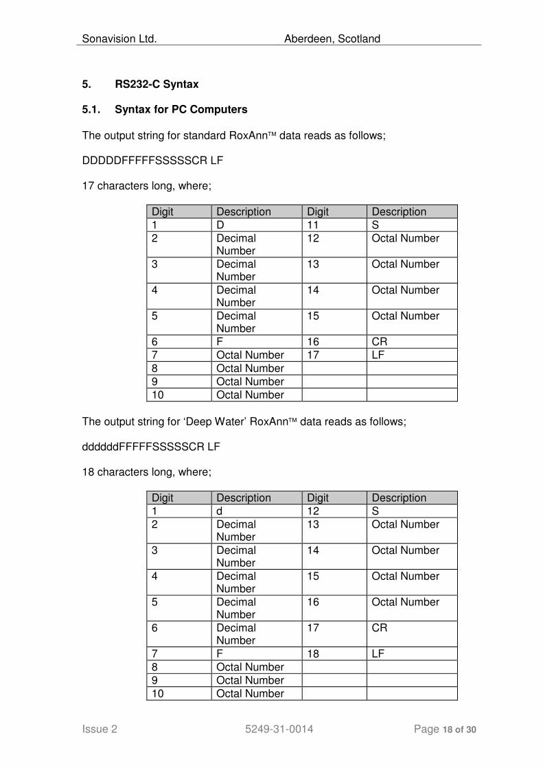
5. RS232-C Syntax 5.1. Syntax for PC Computers
The output string for standard RoxAnn data reads as follows; DDDDDFFFFFSSSSSCR LF 17 characters long, where;
Digit Description Digit Description
1 D 11 S
2 Decimal Number
12 Octal Number
3 Decimal Number
13 Octal Number
4 Decimal Number
14 Octal Number
5 Decimal Number
15 Octal Number
6 F 16 CR
7 Octal Number 17 LF
8 Octal Number
9 Octal Number
10 Octal Number
The output string for ‘Deep Water’ RoxAnn data reads as follows; ddddddFFFFFSSSSSCR LF 18 characters long, where;
Digit Description Digit Description
1 d 12 S
2 Decimal Number
13 Octal Number
3 Decimal Number
14 Octal Number
4 Decimal Number
15 Octal Number
5 Decimal Number
16 Octal Number
6 Decimal Number
17 CR
7 F 18 LF
8 Octal Number
9 Octal Number
10 Octal Number

Sonavision Ltd. Aberdeen, Scotland
Issue 2 5249-31-0014 Page 19 of 30
11 Octal Number
Where D/d = Depth Data The ‘D’ or the ‘d’ field is the number of clock cycles from a precision oscillator that occur between a transmission pulse and a first echo return. Let f = Oscillator frequency (see Section 5.2. RS232 Switch Settings for
RoxAnn), v = Speed of sound, c = Cycle count, c.v. Then Depth = ---- 2.f The ‘F’ field is a representation of the E1 signal level. The ‘S’ field is a representation of the E2 signal level. These values are octal, where; 00008 = 0 Volts
77778 = 4.095 Volts
5.2. RS232 Switch Settings For RoxAnn The settings for switch SW1 on the RS232 Board (Rev 2) are detailed below.
This switch will be set during the build of the RoxAnn system and should not require to be altered. Therefore before any of the settings are changed it is recommended that contact is made with Sonavision.
Switch Number Function
1 Baud Rate
2 Baud Rate
3 Baud rate
4 Protocol
5 Protocol
6 Range
7 Range
Baud Rate
1 2 3 Baud Rate
1 1 1 19200
0 1 1 9600
1 0 1 7200

Sonavision Ltd. Aberdeen, Scotland
Issue 2 5249-31-0014 Page 20 of 30
0 0 1 4800
1 1 0 3600
0 1 0 2400
1 0 0 1200
0 0 0 300
Protocol
4 5 Protocol
1 1 8, n, 1
0 1 8, n, 2
1 0 8, e, 1
0 0 8, n, 1
6 7 Frequency (kHz)
1 1 0.768 - Extended - 10 000m)
0 1 7.68 - (Deep - 2000m*)
1 0 76.8 - (Shallow - 100m)
0 0 7.68 - Standard - 1 000m)
* Note that the output data string is modified for this range and uses a special version of RoxMap. APPENDIX 1 - LIST OF FIGURES The appendix contains technical specification for the RoxAnn unit and a full set of diagrams to facilitate installation. The following lists the figures referred to in the text. Figure 1 System Configuration. Figure 2 System Configuration for ATLAS DESO range of echosounders.
Figure 3 RoxAnn Factory Set-Up Record.. Figure 4 RoxAnn Hardware Components Dimensions. Figure 5 RoxAnn Cabling Information. Figure 6 RoxAnn Square: Sample Calibration or Box File. Figure 7 RoxAnn RS232 Wiring Diagram. Figure 8 Standard RS 232-C connections. Figure 9 RoxAnn Parallel Receiver Back Panel.

Sonavision Ltd. Aberdeen, Scotland
Issue 2 5249-31-0014 Page 21 of 30
Figure 10 RoxAnn Parallel Receiver General Block Diagram. Figure 11 RoxAnn Processor PCB Layout. Figure 12 RoxAnn Head Amplifier PCB. Figure 13 RoxAnn Gimbal PCB. Figure 14 RoxAnn Digital PCB. Figure 15 RoxAnn Analogue PCB
APPENDIX 2 - TECHNICAL SPECIFICATIONS
(1) Power Supply - As per Figure 3. (2) Power Consumption approximately 10 watts. (3) Operating frequency (15 kHz - 210 kHz) - As per Figure
3. (4) Fuse F1 [internal] AC 500MA .(For 240v AC Supply.) (5) Minimum operating water depth determined by pulse
width of host echosounder, typically 1m. using 200 kHz. (6) Maximum operating water depth dependent on power
source level of transmitter and beam width of host echosounder.
(7) DC isolation is achieved by transformer coupling at the
input and optocoupling isolation at RS 232-C output. (8) Output - RS 232-C. (9) Weight 16 kg [including cables]. (10) Dimensions - see Fig. 4. (11) Standard 19" rack mounting possible by removing
external housing. (12) Supplied cable lengths - see Fig. 5.

Sonavision Ltd. Aberdeen, Scotland
Issue 2 5249-31-0014 Page 22 of 30
APPENDIX 3 - TROUBLE SHOOTING Every RoxAnn™ unit is carefully set-up in the factory according to an
exhaustive test and calibration procedure. This ensures that installation of the
system is as quick, straightforward and trouble free as possible. Normally no
specialised equipment or knowledge is required - just follow the instructions in
the RoxAnn™ Installation Manual.
The ‘LEDS’ are green lamps located on the front panel of the RoxAnn™. The
‘left’ LED is on the left as viewed from the front of the unit. The Blanking
Switch (Survey Unit Only), Calibration button and Gain Switch are to be found
on the rear panel of the RoxAnn™system.
Sonavision Ltd. Aberdeen, Scotland
Issue 2 5249-31-0014 Page 23 of 30
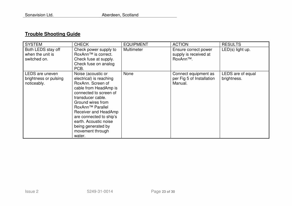
Trouble Shooting Guide
SYSTEM CHECK EQUIPMENT ACTION RESULTS
Both LEDS stay off when the unit is switched on.
Check power supply to RoxAnn™ is correct. Check fuse at supply. Check fuse on analog PCB.
Multimeter Ensure correct power supply is received at RoxAnn™.
LED(s) light up.
LEDS are uneven brightness or pulsing noticeably.
Noise (acoustic or electrical) is reaching RoxAnn. Screen of cable from HeadAmp is connected to screen of transducer cable. Ground wires from RoxAnn™ Parallel Receiver and HeadAmp are connected to ship’s earth. Acoustic noise being generated by movement through water.
None Connect equipment as per Fig 5 of Installation Manual.
LEDS are of equal brightness.
Sonavision Ltd. Aberdeen, Scotland
Issue 2 5249-31-0014 Page 24 of 30
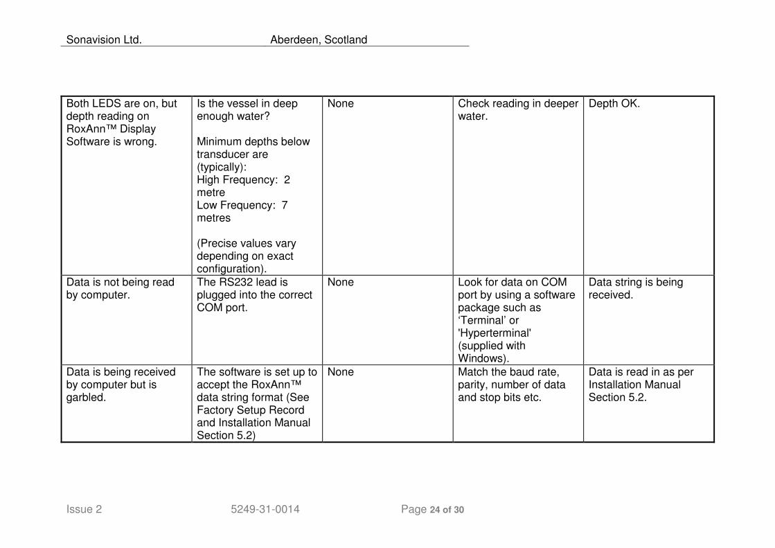
Both LEDS are on, but depth reading on RoxAnn™ Display Software is wrong.
Is the vessel in deep enough water? Minimum depths below transducer are (typically): High Frequency: 2 metre Low Frequency: 7 metres (Precise values vary depending on exact configuration).
None Check reading in deeper water.
Depth OK.
Data is not being read by computer.
The RS232 lead is plugged into the correct COM port.
None Look for data on COM port by using a software package such as ‘Terminal’ or 'Hyperterminal' (supplied with Windows).
Data string is being received.
Data is being received by computer but is garbled.
The software is set up to accept the RoxAnn™ data string format (See Factory Setup Record and Installation Manual Section 5.2)
None Match the baud rate, parity, number of data and stop bits etc.
Data is read in as per Installation Manual Section 5.2.
Sonavision Ltd. Aberdeen, Scotland
Issue 2 5249-31-0014 Page 25 of 30
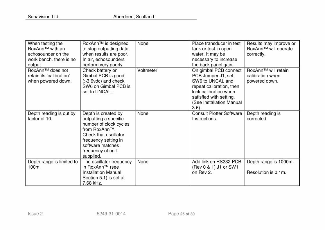
When testing the RoxAnn™ with an echosounder on the work bench, there is no output.
RoxAnn™ is designed to stop outputting data when results are poor. In air, echosounders perform very poorly.
None Place transducer in test tank or test in open water. It may be necessary to increase the back panel gain.
Results may improve or RoxAnn™ will operate correctly.
RoxAnn™ does not retain its ‘calibration’ when powered down.
Check battery on Gimbal PCB is good (>3.6vdc) and check SW6 on Gimbal PCB is set to UNCAL.
Voltmeter On gimbal PCB connect PCB Jumper J1, set SW6 to UNCAL and repeat calibration, then lock calibration when satisfied with setting. (See Installation Manual 3.6).
RoxAnn™ will retain calibration when powered down.
Depth reading is out by factor of 10.
Depth is created by outputting a specific number of clock cycles from RoxAnn™. Check that oscillator frequency setting in software matches frequency of unit supplied.
None Consult Plotter Software Instructions.
Depth reading is corrected.
Depth range is limited to 100m.
The oscillator frequency in RoxAnn™ (see Installation Manual Section 5.1) is set at 7.68 kHz.
None Add link on RS232 PCB (Rev 0 & 1) J1 or SW1 on Rev 2.
Depth range is 1000m. Resolution is 0.1m.
Sonavision Ltd. Aberdeen, Scotland
Issue 2 5249-31-0014 Page 26 of 30
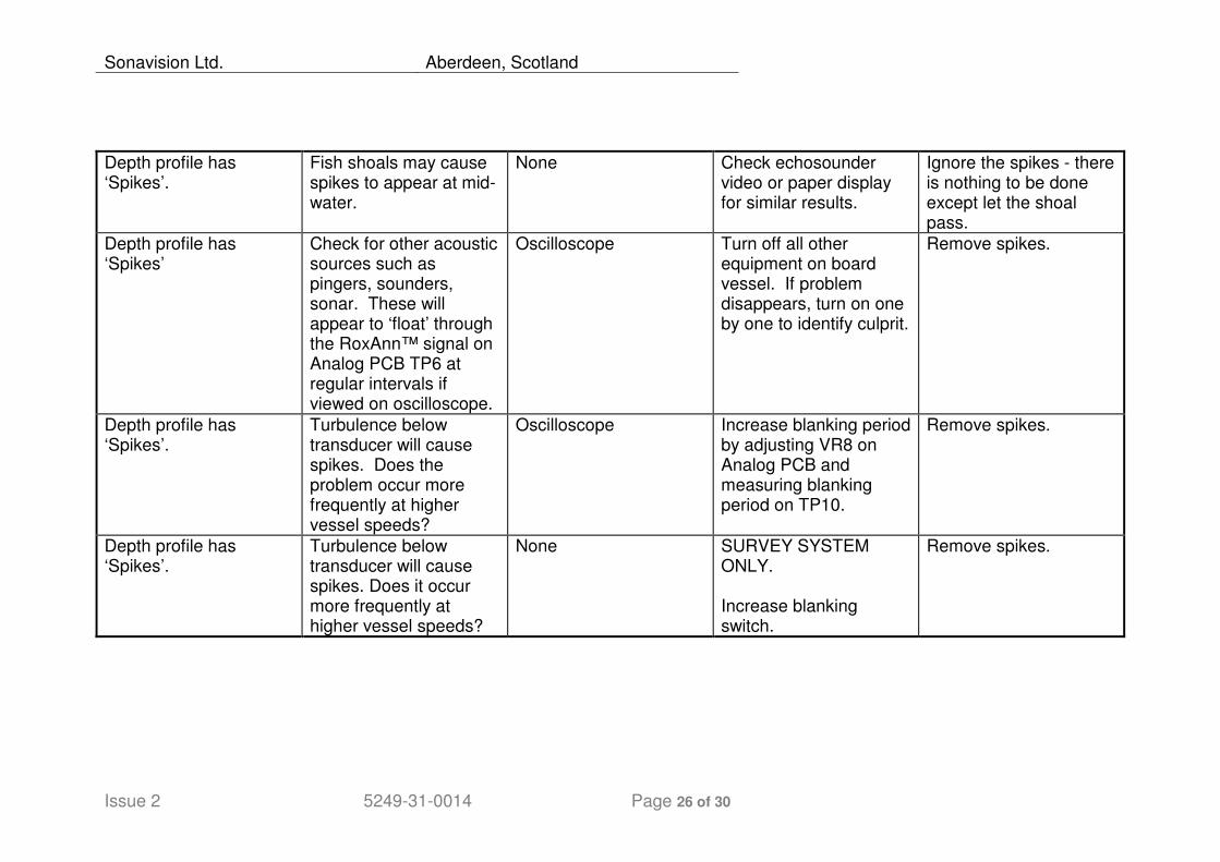
Depth profile has ‘Spikes’.
Fish shoals may cause spikes to appear at mid-water.
None Check echosounder video or paper display for similar results.
Ignore the spikes - there is nothing to be done except let the shoal pass.
Depth profile has ‘Spikes’
Check for other acoustic sources such as pingers, sounders, sonar. These will appear to ‘float’ through the RoxAnn™ signal on Analog PCB TP6 at regular intervals if viewed on oscilloscope.
Oscilloscope Turn off all other equipment on board vessel. If problem disappears, turn on one by one to identify culprit.
Remove spikes.
Depth profile has ‘Spikes’.
Turbulence below transducer will cause spikes. Does the problem occur more frequently at higher vessel speeds?
Oscilloscope Increase blanking period by adjusting VR8 on Analog PCB and measuring blanking period on TP10.
Remove spikes.
Depth profile has ‘Spikes’.
Turbulence below transducer will cause spikes. Does it occur more frequently at higher vessel speeds?
None SURVEY SYSTEM ONLY. Increase blanking switch.
Remove spikes.
Sonavision Ltd. Aberdeen, Scotland
Issue 2 5249-31-0014 Page 27 of 30
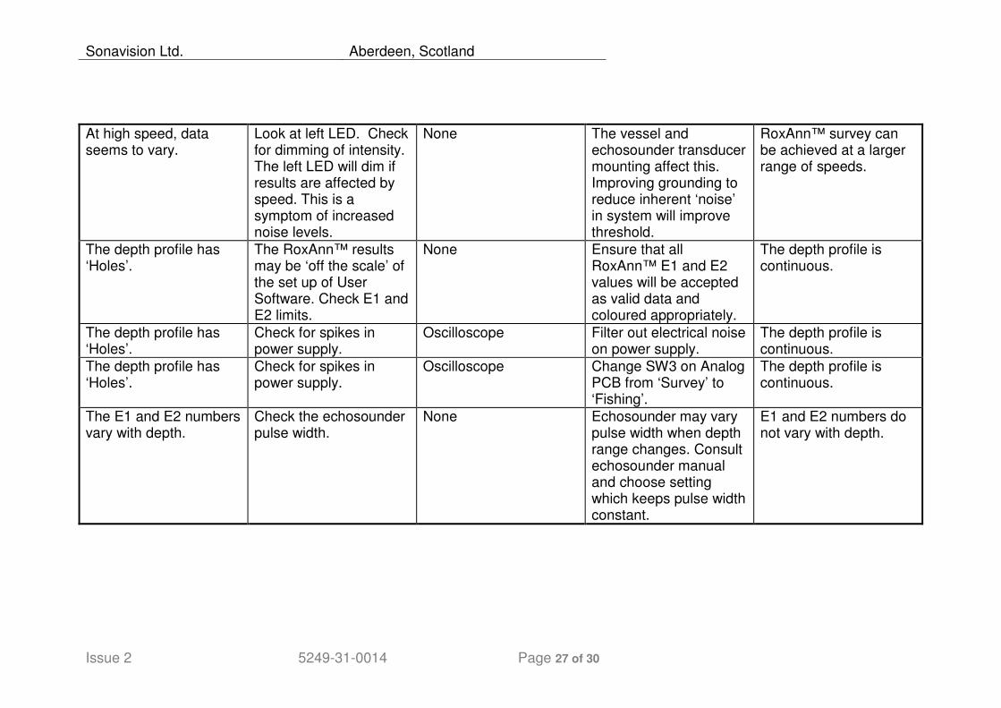
At high speed, data seems to vary.
Look at left LED. Check for dimming of intensity. The left LED will dim if results are affected by speed. This is a symptom of increased noise levels.
None The vessel and echosounder transducer mounting affect this. Improving grounding to reduce inherent ‘noise’ in system will improve threshold.
RoxAnn™ survey can be achieved at a larger range of speeds.
The depth profile has ‘Holes’.
The RoxAnn™ results may be ‘off the scale’ of the set up of User Software. Check E1 and E2 limits.
None Ensure that all RoxAnn™ E1 and E2 values will be accepted as valid data and coloured appropriately.
The depth profile is continuous.
The depth profile has ‘Holes’.
Check for spikes in power supply.
Oscilloscope Filter out electrical noise on power supply.
The depth profile is continuous.
The depth profile has ‘Holes’.
Check for spikes in power supply.
Oscilloscope Change SW3 on Analog PCB from ‘Survey’ to ‘Fishing’.
The depth profile is continuous.
The E1 and E2 numbers vary with depth.
Check the echosounder pulse width.
None Echosounder may vary pulse width when depth range changes. Consult echosounder manual and choose setting which keeps pulse width constant.
E1 and E2 numbers do not vary with depth.
Sonavision Ltd. Aberdeen, Scotland
Issue 2 5249-31-0014 Page 28 of 30
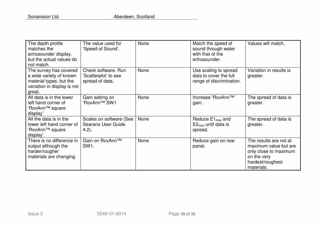
The depth profile matches the echosounder display, but the actual values do not match.
The value used for ‘Speed of Sound’.
None Match the speed of sound through water with that of the echosounder.
Values will match.
The survey has covered a wide variety of known material types, but the variation in display is not great.
Check software. Run ‘Scatterplot’ to see spread of data.
None Use scaling to spread data to cover the full range of discrimination.
Variation in results is greater.
All data is in the lower left hand corner of ‘RoxAnn™ square display’
Gain setting on ‘RoxAnn™ SW1
None Increase ‘RoxAnn™’ gain.
The spread of data is greater.
All the data is in the lower left hand corner of ‘RoxAnn™ square display’.
Scales on software (See Searano User Guide 4.2).
None Reduce E1max and E2max until data is spread.
The spread of data is greater.
There is no difference in output although the harder/rougher materials are changing.
Gain on RoxAnn™ SW1.
None Reduce gain on rear panel.
The results are not at maximum value but are only close to maximum on the very hardest/roughest materials.
Sonavision Ltd. Aberdeen, Scotland
Issue 2 5249-31-0014 Page 29 of 30
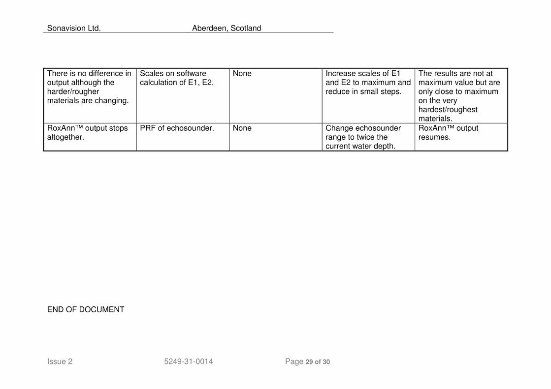
There is no difference in output although the harder/rougher materials are changing.
Scales on software calculation of E1, E2.
None Increase scales of E1 and E2 to maximum and reduce in small steps.
The results are not at maximum value but are only close to maximum on the very hardest/roughest materials.
RoxAnn™ output stops altogether.
PRF of echosounder. None Change echosounder range to twice the current water depth.
RoxAnn™ output resumes.
END OF DOCUMENT

Sonavision Ltd. Aberdeen, Scotland
Issue 2 5249-31-0014 Page 30 of 30