Embed Size (px)
Citation preview

Operation and Installation Manual
Model 40 Series Granulators
Important! Read Carefully Before Attempting to Install or Operate Equipment

Page 2 40 Series Granulators
CUMBERLAND EUROPE LIMITED
OPERATION AND MAINTENANCE MANUAL
CUMBERLAND
GRANULATOR
MODELS 4050/4070/40100
CUSTOMER: ____________________________________
CUSTOMER P.O.: ____________________________________
SERIAL NO: _____________________________________
ASSEMBLY ORDER NO: _____________________________________
This manual and the information within is provided to our customers for the purpose of
operating and maintaining the equipment listed above in a safe and productive manner. It
is not to be given or made available to anyone who would use this information to the
detriment of CUMBERLAND EUROPE LTD.
When ordering replacement parts, please include part numbers, serial number, assembly
order number.
CUMBERLAND Cumberland Europe Ltd.
Daniels Industrial Estate
Bath Road, Stroud
Gloucestershire GL5 3TJ
England
Tel: (01453) 768980
Fax: (01453) 768990

40 Series Granulators Page 3
Safety Considerations
Cumberland Europe Ltd. granulators are designed to
provide safe and reliable operation when installed and
operated within design specifications, following national
and local safety codes.
To avoid possible personal injury or equipment damage
when installing, operating, or maintaining this granulator,
use good judgment and follow these safe practices:
LEARN AND OBEY your company’s safety policy
regarding granulating equipment.
MOVING OR LIFTING THE GRANULATOR:
Although our equipment is built and engineered for
great ruggedness in operation, care must be taken when
moving the machine along the floor or lifting it.
Damage may occur to sheet metal covers, electrical
cabinets, or small brackets if pressure is applied to
them when moving the granulator. When lifting the
granulator, be certain of total machine weight and the
capability of the lifting equipment (see the Granulator
Specification Sheets for machine weights and
dimensions).
GRANULATOR LOCATION: Adequate area for
routine maintenance should be provided in order to
open the machine for knife, screen, or cleanout service.
Proper service area clearances also should allow
people who are working on the machine to be clearly
visible to others, thereby reducing the potential safety
hazards.
SAFE HOUSEKEEPING: The work area must be
kept clean and uncluttered to allow personnel safe
movement around the granulator during periods of
operation or maintenance. No hand tools or other
metal objects should be left on or about the machine.
Any tools or other metal objects which mistakenly fall
into the hopper feed opening can cause severe damage
to internal cutting chamber and screen chamber
components.

Page 4 40 Series Granulators
SAFETY GLASSES OR A FACE SHIELD MUST
ALWAYS BE WORN when servicing or operating
the machine. Although our machines are designed for
the maximum in flyback control, caution must be used
when operating near the area of the hopper feed
opening in order to guard against unexpected material
flyback.
EAR PROTECTION may be required when
operating the machine during granulation of very
hard/noisy materials, over a prolonged period of time.
NEVER attempt to operate the granulator unless it is
fully assembled with all guards and interlocks in place
and functional.
OBSERVE all danger, warning, caution and safety
labels on the equipment.
Upon completion of any machine maintenance, be
certain ALL SAFETY GUARDS AND COVERS are
securely and properly fastened prior to resuming
machine operation. All fasteners must be in place and
properly tightened. ANY SHORTCUTS MAY
RESULT IN INJURY TO PERSONNEL OR
DAMAGE TO EQUIPMENT.
NEVER wear any loose fitting clothes, neckties, or
dangling items such as earrings, belts or shoestrings.
Jewellery such as wristwatches, bracelets, or rings
should NEVER be worn. Long hair must be tied back
or placed in a tight fitting hairnet. NEVER lean
against or rest hands/feet on the granulator when it is
in operation or open for maintenance. NEVER stand
on the granulator when it is in operation.
ROTATION OF MOTORS: All rotating items in the
granulator are clearly marked on the machine. Always
check for proper rotation of motors.
ELECTRICAL GROUNDING: All electrical
equipment on the granulator must be grounded.

40 Series Granulators Page 5
ALWAYS DISCONNECT AND LOCKOUT THE
MAIN ELECTRICAL POWER TO THE
GRANULATOR BEFORE PERFORMING ANY
SERVICE.
SAFETY INTERLOCKS MUST NOT BE
BYPASSED. The mechanical and electrical safety
interlocks ensure the safety of personnel. They should
never be tampered with or removed for ANY reason.
They should be frequently checked by a qualified
mechanic for proper operation.
NEVER modify the machine configuration or any
individual component without written consent from
Cumberland Europe Ltd.
SAFETY CHOCK (MODEL 40100 ONLY)
Cumberland has long recognized the importance of safety and has designed and
manufactured it’s equipment with operator safety as a prime consideration. As a user, we
expect you will abide by the foregoing recommendations in order to make operator safety
a reality.
SAFETY IS NO ACCIDENT

Page 6 40 Series Granulators
Table of Contents
Safety Considerations 3
Table of Contents 6
Charts and Figures 9
1 General Information 10
1-1 Introduction 10
1-2 General Description 11
1-3 Granulator Specifications 12
2 Shipping Information 14
2-1 Unpacking and Inspection 14
2-2 In the Event of Shipping Damages 14
2-3 If the Shipment is Not Complete 15
2-4 If the Shipment is Not Correct 15
2-5 Returns 15
2-6 Uncrating 16
3 Installation 17
3-1 Scope 17
3-2 General 17
3-3 Set-up 17
3-4 Electrical Service Connections 20
3-5 High Amperage Readings 20
4 Accessing Cutting Chamber 21
4-1 Opening Cutting Chamber 21
4-2 Closing Cutting Chamber 21

40 Series Granulators Page 7
5 Accessing Screen Chamber 22
5-1 Opening Screen Chamber 22
5-2 Closing Screen Chamber 23
6 Sequence of Operation 24
6-1 Scope 24
6-2 Electrical Test 24
7 Startup Checklist 27
7-1 Introduction 27
7-2 Fan Evacuation 27
7-3 Granulator Startup Checklist 27
Are all personnel clear of the machine and optional fan? 28
8 Operation 29
8-1 Operation Instructions 29
8-2 Temporary Machine Stops 29
8-3 Final Machine Stops 30
8-4 Emergency Stops 30
9 Routine Maintenance 32
9-1 Lubrication Specifications 32
9-1-1 Description 32
9-1-2 Screw Jack Lubrication Instructions 32
Recommended Grease Product Names (Screw Jack) 32
9-2 Motor & Belts Servicing 32
9-3 Knife Removal & Adjustment 35
9-4 Rotor Knife Removal 36
9-5 Rotor Knife Sharpening 36
9-6 Rotor Knife Installation 37
9-7 Bed Knife Sharpening 38
9-8 Bed Knife Installation & Setting 39
9-9 Preventative Maintenance Service 41

Page 8 40 Series Granulators
9-10 Recommended Torque For Knife Bolts 41
10 Troubleshooting 42
12 Spare Parts 46
12-1 Recommended Spare Parts 46
12-2 Additional Parts 46
Service Notes 47
Service Notes 48

40 Series Granulators Page 9
Charts and Figures
1 Granulator Specifications Table Granulator Dimensions 12
2 Belt Span and Deflection
Belt Deflection Force Table 33-34
3 Rotor Knife Drawings 37
4 Bed Knife Drawings 40
5 Recommended Bolt Torque 42
Page 10 40 Series Granulators
1 General Information
1-1 Introduction
This manual is intended for use as a guide and reference for
personnel who will be installing, operating, and maintaining
the Cumberland 40 Series Granulator. The purpose is to aid
these individuals in applying efficient, proven techniques,
which will enhance productivity.
This Introduction includes a brief functional description, a
physical description, and machine specifications for these
granulators. Additional sections within the manual provide
instructions for installation, pre-operation, preventative
maintenance, and corrective maintenance.
Section 2, Shipping Information, includes all required data
for receiving, unpacking & inspecting the granulator.
Section 3, Installation, provides information on the proper
setup of the granulator. Also included are illustrations,
which will aid in utilizing techniques to accomplish these
tasks efficiently. We can provide the assistance of a factory
trained technician, for a nominal charge, who will help in
training your operator(s).
Pre-operation Instructions include procedures, checks, and
adjustments, which should be followed before commencing
with operation of the granulator. These instructions are
intended to supplement standard shop procedures performed
at shift, daily, and weekly intervals.
The Troubleshooting Section is intended to serve both as a
guide for identification and location of most common
problems and as a source of detailed assembly and
disassembly instructions for those areas of the equipment
requiring service.
The Spare Parts Section contains a partial list of
recommended parts, which may require replacement. Refer
to the Spare Parts Manual for a comprehensive listing of
components, which can be purchased.

40 Series Granulators Page 11
1-2 General Description
Cumberland granulators are designed to uniformly and
consistently size reduce your scrap. They have been
engineered to consistently deliver clean granulate with a
minimum of “fines”.
The rotor, on which the cutting knives are mounted, is a
fabricated steel unit supported by bearings mounted outside
the cutting chamber. A motor drives the rotor, which is
capable of producing high torque loads. The granulator is
equipped with a magnetic starter that is protected by
manually resettable overload heaters. The slanted rotor
knives produce a scissors cutting action, which reduce the
possibility of feedstock jamming in the cutting chamber.
The control enclosure houses all of the necessary wiring,
fuses, overload heaters, motor starter coils, along with the
24V control transformer and granulator operating controls.
Page 12 40 Series Granulators
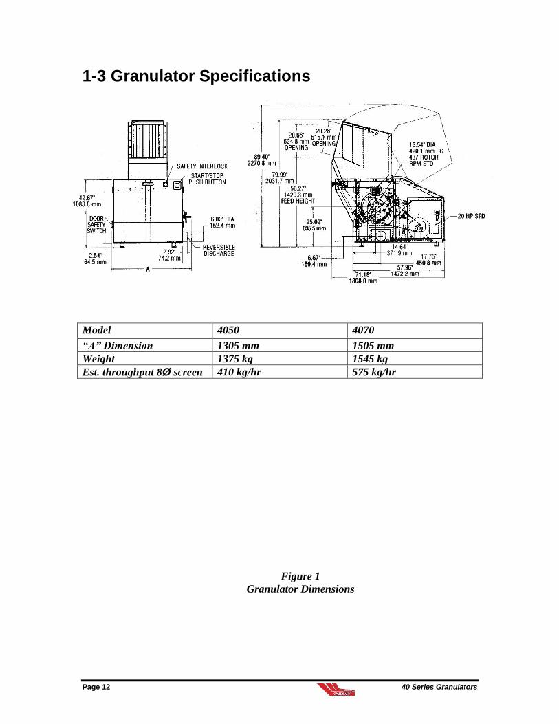
1-3 Granulator Specifications
Model 4050 4070
“A” Dimension 1305 mm 1505 mm
Weight 1375 kg 1545 kg
Est. throughput 8Ø screen 410 kg/hr 575 kg/hr
Figure 1
Granulator Dimensions

40 Series Granulators Page 13

Page 14 40 Series Granulators
2 Shipping Information
2-1 Unpacking and Inspection
You should inspect your Cumberland 40 Series granulator
for possible shipping damage. If the container and packing
materials are in re-usable condition, save them for
reshipment if necessary.
Thoroughly check the equipment for any damage that might
have occurred in transit. In case of breakage, damage,
shortage, or incorrect shipment refer to the following
sections.
2-2 In the Event of Shipping Damages
Important!
According to the contract terms and conditions of the Carrier,
the responsibility of the Shipper ends at the time and place of shipment.
Notify the transportation company’s local agent if you
discover damage.
Hold the damaged goods and packing material for the
examining agent’s inspection. Do not return any goods
to Cumberland Europe Ltd. before the transportation
company inspection and authorization.
File a claim against the transportation company.
Substantiate the claim by referring to the agent’s report.
A certified copy of our invoice is available upon
request. If the shipment was prepaid, call us for a
receipted transportation bill.
Advise Cumberland Europe Ltd. regarding your wish
for assistance and to obtain an RMA (return material
authorization) number.

40 Series Granulators Page 15
2-3 If the Shipment is Not Complete
Check the packing list. You should have:
Cumberland Europe Ltd. 40 Series granulator
Bill of lading for equipment shipped
Operating and Installation packet
Electrical schematic and panel layout drawings
Re-inspect the container and packing material to see if you
missed any smaller items during unpacking. Determine that
the item was not inadvertently taken from the area before
you checked in the shipment. Notify Cumberland Europe
Ltd. immediately of the shortage.
2-4 If the Shipment is Not Correct
If the shipment is not what you ordered, contact the
Cumberland Europe Ltd. shipping department
immediately (Tel. +44 (0)1453 768980).
Have the order number and item number available.
Hold the items until you receive shipping instructions.
2-5 Returns
Important!
Do not return any damaged or incorrect items
until you receive shipping instructions from Cumberland Europe Ltd.
Page 16 40 Series Granulators
2-6 Uncrating
40 Series Granulator
40 Series granulators are shipped mounted on a wooden skid
then blocked and banded to prevent movement. All non-painted
items subject to corrosion are coated with a quality rust
preventative and the machine is then covered with heavy duty
polyethylene to protect it from moisture and dirt.
Cumberland granulators are normally shipped completely
assembled unless the size of the machine or an agreement for
special shipping arrangements causes partial disassembly.
If inspection revealed no shipping damage, unpack the unit by
removing the polyethylene covering and banding. For detailed
uncrating information, follow the instructions listed below:
1. Remove outer sheet covering. Cut banding.
2. Use a pry bar to remove the blocks securing the unit to the
skid.
3. Insert forks between skid and granulator from the front
side (infeed opening side) as far as possible without
touching the front of the unit. The forks must be
equidistant from the centerline of the unit and the unit
must be balanced on the forks.
4. Lift the unit off the skid with a fork truck. Lift slowly and
only high enough to clear the skid. Use a pry bar if
necessary to carefully remove the skid from the unit.
5. Lower slowly onto the floor.
Important!
Retain the crating material for reshipping the granulator in case hidden
shipping damage is found.
CAUTION!
DO NOT attempt to lift the granulator by means of
any shaft or protruding member,
ESPECIALLY THE HOPPER
40 Series Granulators Page 17
3 Installation
3-1 Scope
This section contains all instructions required for
experienced installation personnel to install the
Cumberland granulator and prepare it for production. It is
essential to follow all instructions carefully and in the
sequence presented. Be sure to observe all DANGER,
WARNING, and CAUTION statements in order to
prevent personal injury or machine damage, and to observe
all NOTE statements which are designed to assist in the
performance of procedures.
3-2 General
The site selected for installation of the granulator should be
prepared in advance. Be certain that the area to be
occupied by the machine is clean, level and free of
obstructions. The site selected must have a floor rated to
easily support the weight of the machine. A concrete floor
of 100 mm minimum in thickness is recommended.
3-3 Set-up
Make certain the floor is clean, level, and free of
obstructions before placing the machine into position.
Visually inspect the hopper infeed opening to insure that no
stray packing material or debris are present.
Page 18 40 Series Granulators
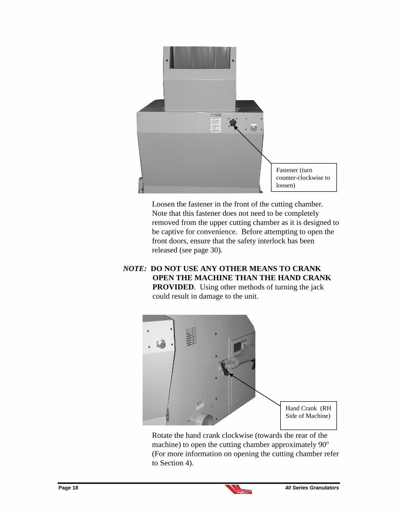
Loosen the fastener in the front of the cutting chamber.
Note that this fastener does not need to be completely
removed from the upper cutting chamber as it is designed to
be captive for convenience. Before attempting to open the
front doors, ensure that the safety interlock has been
released (see page 30).
NOTE: DO NOT USE ANY OTHER MEANS TO CRANK
OPEN THE MACHINE THAN THE HAND CRANK
PROVIDED. Using other methods of turning the jack
could result in damage to the unit.
Rotate the hand crank clockwise (towards the rear of the
machine) to open the cutting chamber approximately 90o
(For more information on opening the cutting chamber refer
to Section 4).
Fastener (turn
counter-clockwise to
loosen)
Hand Crank (RH
Side of Machine)
40 Series Granulators Page 19
CAUTION!
The knives mounted on the rotor and also located at the edges of the cutting
chamber are extremely sharp. Always wear heavy gloves and exercise care
when working in the cutting chamber.
Wipe out the inside of the hopper and upper cutting
chamber. Carefully inspect the interior of the cutting
chamber for foreign material or debris. Slowly turn the
rotor by hand to verify that it rotates freely and without
obstruction or contact between the rotor and bed knives.
Before closing the cutting chamber, check the chamber to
insure that nothing has been left inside the machine and that
the rotor restraint pin has been removed. Rotate the hand
crank counter-clockwise (towards the front of the machine)
until the cutting chamber is fully closed.
Lower the screen chamber until it comes to rest.
Remove the screens and place them on their side. Wipe out
the screen chamber and transition. Once cleaned, place the
screen back into position. Raise the screen chamber and
tighten the (2) fasteners to hold the screen chamber and
cutting chamber securely closed. Connect the fan transition
(optional) or replace the bin to prepare the machine for
operation. Position and connect any optional accessory
equipment such as fans, conveyors, and separators. Ensure
all tubing joints are securely clamped and supported.
Make certain all electrical connections are properly made
and supported between accessories and the control
enclosure. (Refer to the wiring diagrams for wire and
terminal connections.)
Open the sheave guard (LH) by removing the fastener
attaching the cover. Check the belts for proper tension and
alignment (refer to Section 9-2). Upon completion, close
the sheave guard by placing the cover back into position,
insert all of the fasteners originally removed, and tighten
them fully.

Page 20 40 Series Granulators
3-4 Electrical Service Connections
Carefully check the diagrams packed with the machine. All
internal wiring has been done at the factory and safety
interlocks have been verified for proper functioning before
shipment. It is only necessary to connect the electrical
power source to the machine at the control enclosure.
WARNING!
The customer’s disconnecting means and branch circuit protection must also
be in compliance with the National Electric Code and all Local Codes.
3-5 High Amperage Readings
NOTE: Make sure the granulator is not drawing excessive
amperage.
1. Check appropriate amperage as listed on the motor
nameplate.
2. Measure amperage with ammeter by connecting
ammeter to incoming power feed wires. Make sure
machine is not drawing more than amperage listed on
the nameplate. The amperage will change according to
motor size.
3. If amperage exceeds the amount listed on nameplate,
check the following:
Sharpness of knives
Quoted feed rate of granulator

40 Series Granulators Page 21
4 Accessing Cutting Chamber
4-1 Opening Cutting Chamber
1. Allow material to run out of the cutting chamber.
2. Shut OFF and LOCKOUT all power, including the main
disconnect switch.
3. If equipped with optional sound enclosure, open front
doors, after ensuring the safety interlock has been released
(see page 30).
4. Loosen fasteners on front of machine. They are designed to
remain with the screen chamber.
5. Rotate handle (right side of machine) towards the rear of
the machine.
WARNING!
DO NOT USE ANY OTHER MEANS TO CRANK OPEN THE MACHINE OTHER
THAN THE HAND CRANK PROVIDED. Using other methods of turning the jack will result in damage to the unit.
NOTE: The cutting chamber is designed to open 90o to access the
knives, but can be left open at any position on the way up
depending on the reason for opening. The jack screw is a
self-locking acme screw that will not back travel.
CAUTION!
New or resharpened knives should be handled with extreme care. It is
suggested that the sharp cutting edges be covered with tape to prevent damage
to the knives or injury to personnel during installation.
4-2 Closing Cutting Chamber
1. Double check the cutting chamber area for tools, rags, and
other debris left in the area and that the rotor restraint pin
has been removed.
2. Rotate the crank handle towards the front of the machine.
3. Raise screen cradle and tighten (2) fasteners.
Page 22 40 Series Granulators
4. Tighten the fasteners in the front of the cutting chamber.
5 Accessing Screen Chamber
5-1 Opening Screen Chamber
1. Allow all material to run out of the cutting chamber and
screen chamber.
2. Shut OFF and LOCKOUT all power including the main
disconnect switch.
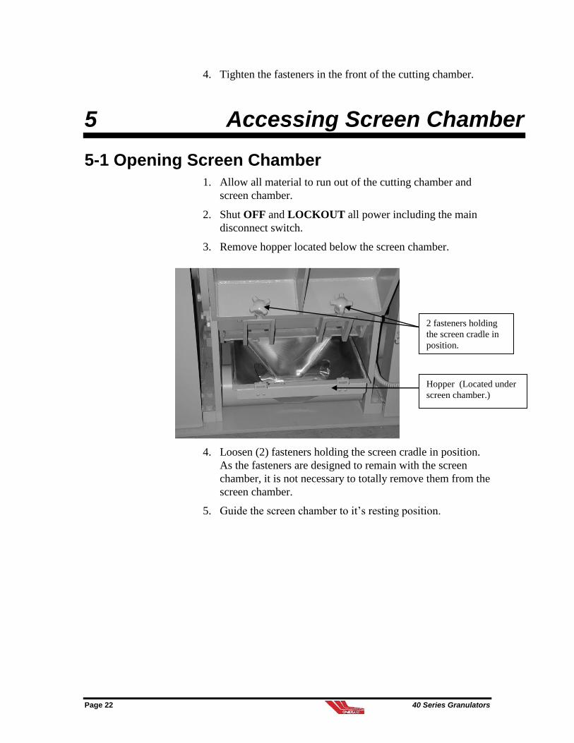
3. Remove hopper located below the screen chamber.
4. Loosen (2) fasteners holding the screen cradle in position.
As the fasteners are designed to remain with the screen
chamber, it is not necessary to totally remove them from the
screen chamber.
5. Guide the screen chamber to it’s resting position.
Hopper (Located under
screen chamber.)
2 fasteners holding
the screen cradle in
position.
40 Series Granulators Page 23
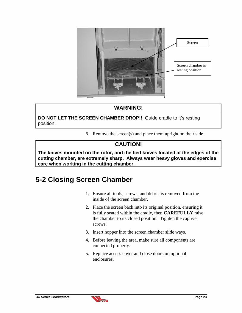
WARNING!
DO NOT LET THE SCREEN CHAMBER DROP!! Guide cradle to it’s resting position.
6. Remove the screen(s) and place them upright on their side.
CAUTION!
The knives mounted on the rotor, and the bed knives located at the edges of the
cutting chamber, are extremely sharp. Always wear heavy gloves and exercise
care when working in the cutting chamber.
5-2 Closing Screen Chamber
1. Ensure all tools, screws, and debris is removed from the
inside of the screen chamber.
2. Place the screen back into its original position, ensuring it
is fully seated within the cradle, then CAREFULLY raise
the chamber to its closed position. Tighten the captive
screws.
3. Insert hopper into the screen chamber slide ways.
4. Before leaving the area, make sure all components are
connected properly.
5. Replace access cover and close doors on optional
enclosures.
Screen chamber in
resting position.
Screen

Page 24 40 Series Granulators
6 Sequence of Operation
6-1 Scope
This section contains the information required to carry out pre-
operational procedures, and the checklist of items, which
should always be reviewed prior to a production run.
DANGER!
Before undertaking any machine repairs or maintenance, always make certain that
the machine disconnect switch is turned to the OFF position or that the control enclosure is disconnected from the main power source. Lock out all sources of power including the main disconnect switch and follow all of your plant lockout procedures.
6-2 Electrical Test
Before applying power to the machine, check the incoming
voltage from L1 to L2, L2 to L3, and L1 to L3 (see the wiring
diagram packed with the machine). The voltage should be the
same as indicated on the silver tag in the control enclosure. If
the voltage is not the same, contact the Cumberland Service
Department for voltage modification instructions at +44 (0)
1453 768980.
Once it has been determined the voltages are correct, it is
necessary to start the motors and check for the proper direction
of rotation.
Turn the main disconnect switch to the ON position.
Push and hold in the spring loaded knob next to the door
fastener, then press the airveyor start pushbutton to
start the fan motor. Visually compare the direction of
the motor shaft rotation to the rotation arrow label
(clockwise when viewed from the shaft end). If the
motor turns in the opposite direction, reverse any two
incoming power leads.

40 Series Granulators Page 25
Press the granulator start pushbutton and visually check
the direction of rotation of the rotor pulley through the
viewing aperture on the left hand side of the machine.
Correct rotation is as indicated by the arrow nameplates
above the viewing aperture. If the rotor turns in the
opposite direction, reverse any two incoming power
leads to the motor.
Once the rotation direction is correct, the remaining electrical
controls need to be tested as follows:
Press the granulator stop pushbutton and allow the
machine to stop.
For granulators equipped with conveyors, etc., test their
operation also by pressing the appropriate pushbutton.
Check all emergency stop pushbuttons to ensure all
motion stops.
-Notes-

Page 26 40 Series Granulators

40 Series Granulators Page 27
7 Startup Checklist
7-1 Introduction
After all electrical and mechanical machine elements have been
inspected and any defects corrected, the machine can be put
into production once the start-up checklist has been referred to.
7-2 Fan Evacuation
Cumberland granulators can be supplied with an optional fan
system to provide efficient, continuous evacuation of granulate
from the machine. Cumberland offers a large variety of fan
configurations. The following information is intended to be
representative of the basic functioning and design of a fan,
rather than being specific to one particular configuration.
Please follow the instructions listed below for optimal fan
operation, if your unit is equipped with this option.
7-3 Granulator Startup Checklist
Have all installation and preparation instructions been read
and followed?
Have the granulator operator and all other necessary
personnel been fully trained on machine operation and all
safety mechanisms?
Have sufficient location clearances been allowed?
Have all motors been checked for rotation?
Have all machine controls, pushbuttons, and limit switch
safeties been checked for proper functioning?
Have the cutting chamber and screen chamber been
checked for foreign matter?
Have the drive belts been checked for alignment and
tension?
Is the machine properly closed with all visible fasteners
tight?
Are all accessory components electrically and mechanically
connected with proper support and with all fasteners tight?

Page 28 40 Series Granulators
Are cyclonic air separator and filter units empty? (optional
equipment)
Has the fan (optional) been verified for proper rotation
direction?
Are all electrical enclosure boxes tightly closed and
clamped shut?
Are all personnel clear of the machine and optional fan?

40 Series Granulators Page 29
8 Operation
8-1 Operation Instructions
1. Prior to machine startup -- All doors, covers, guards, and
limit switches must be in place, securely fastened, and
functional. All accessory components must be properly
connected. If the granulator has a bin, make sure it is
installed.
2. Turn the main disconnect to the ON position.
3. Start the granulator and fan by pushing and holding in the
airveyor start pushbutton, which resets the safety relay and
starts the fan, then pressing the granulator start pushbutton
at the operator station.
4. Load feedstock at a uniform rate that does not exceed the
capacity of the machine.
NOTE: For color and/or material changes, allow all existing material to
clear the granulator and it’s downstream equipment before
stopping the machine in order to minimize cleaning
requirements.
Refer to Sections 4 and 5 for how to open the cutting chamber
and screen chamber in order to obtain access to other machine
areas for cleanout.
NOTE: If there is an access door on the hopper for inspection or
cleanout purposes that is limit switch interlocked, make certain
that the limit switch actuator bracket is re-installed and is
properly in contact with the limit switch or the machine will not
start.
8-2 Temporary Machine Stops
When temporarily stopping the machine, allow all material
to run out of the cutting chamber. NEVER try to restart the
machine with material remaining inside the cutting
chamber.

Page 30 40 Series Granulators
8-3 Final Machine Stops
When shutting the machine down, allow all material to
drop into the bin or pass through the fan and into the
cyclonic air separator (optional) before pressing the
granulator stop pushbutton.
8-4 Emergency Stops
Feedstock must be cleaned out of the hopper and cutting
chamber prior to restarting the machine.
NOTE: The Cumberland 40 Series granulators are not designed for small
purging, chunks of solid plastic or other heavy wall cross-
sectional pieces.
NOTE: When the granulator is being stopped, a movement sensor is
fitted which senses when rotation of the rotor has ceased.
Approx. 10 secs. after movement has ceased, an indicator lamp
on the operator station will illuminate and the key located in the
Fortress Interlock can be withdrawn and used to unlock the
spring loaded interlock bolt locking the front doors.
DO NOT ATTEMPT TO OPEN THE FRONT DOORS
UNLESS THE SPRING LOADED BOLT ASSEMBLY HAS
BEEN UNDONE.
40 Series Granulators Page 31
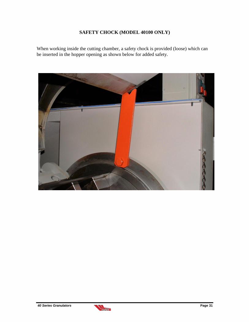
SAFETY CHOCK (MODEL 40100 ONLY)
When working inside the cutting chamber, a safety chock is provided (loose) which can
be inserted in the hopper opening as shown below for added safety.

Page 32 40 Series Granulators
9 Routine Maintenance
9-1 Lubrication Specifications
9-1-1 Description
All Cumberland 40 Series machines are equipped with
rotor bearings that are prelubricated and sealed for life and
therefore require no further lubrication.
9-1-2 Screw Jack Lubrication Instructions
Lifting screws should be checked periodically to ensure that
they are adequately lubricated. It is recommended that the
screw jack be lubricated at monthly intervals, unless
experience indicates that re-greasing should occur at more
regular intervals.
Recommended Grease Product Names (Screw Jack)
Exxon Nevulla EPO -20 to 150oF
Mobil Mobilux EPO -10 to 220oF
Arco Litholine HEP1 -10 to 220oF
Gulf Gulf Crown EPO -20 to 220oF
9-2 Motor & Belts Servicing
Prior to startup of this machine, it is recommended that the
drive belt tension be checked for proper “RUN IN”
deflection force as listed in column A of the table on page
35.
After the equipment has run between 24 and 48 hours, drive
belt tension must be checked for proper “OPERATIONAL”
deflection as listed in column B of the table on page 35.
A V-belt drive will successfully transmit its rated capacity
if the belts are properly tensioned. The method of
tensioning is explained here in detail for your information.
40 Series Granulators Page 33
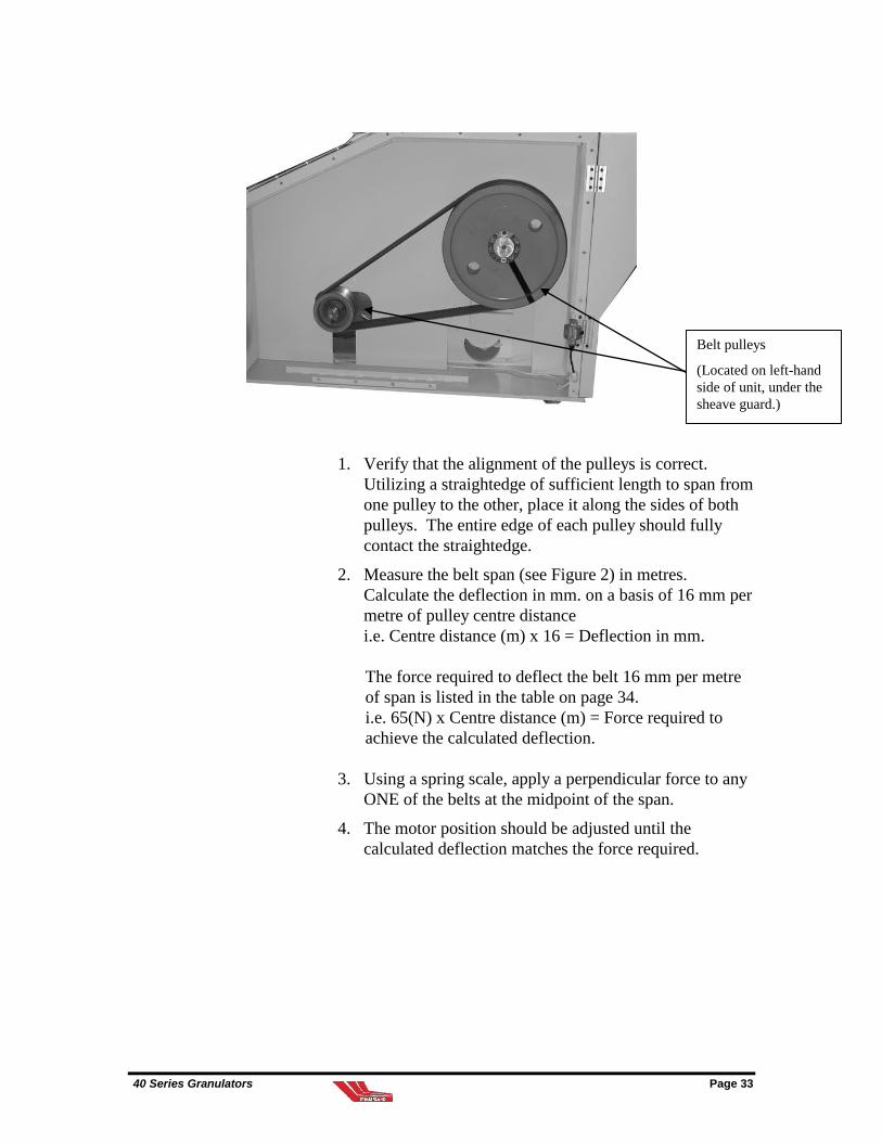
1. Verify that the alignment of the pulleys is correct.
Utilizing a straightedge of sufficient length to span from
one pulley to the other, place it along the sides of both
pulleys. The entire edge of each pulley should fully
contact the straightedge.
2. Measure the belt span (see Figure 2) in metres.
Calculate the deflection in mm. on a basis of 16 mm per
metre of pulley centre distance
i.e. Centre distance (m) x 16 = Deflection in mm.
The force required to deflect the belt 16 mm per metre
of span is listed in the table on page 34.
i.e. 65(N) x Centre distance (m) = Force required to
achieve the calculated deflection.
3. Using a spring scale, apply a perpendicular force to any
ONE of the belts at the midpoint of the span.
4. The motor position should be adjusted until the
calculated deflection matches the force required.
Belt pulleys
(Located on left-hand
side of unit, under the
sheave guard.)
Page 34 40 Series Granulators
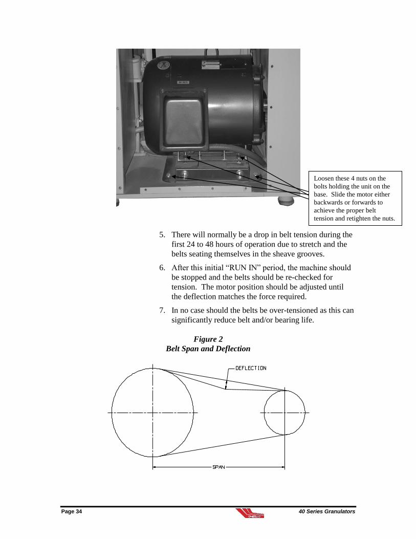
5. There will normally be a drop in belt tension during the
first 24 to 48 hours of operation due to stretch and the
belts seating themselves in the sheave grooves.
6. After this initial “RUN IN” period, the machine should
be stopped and the belts should be re-checked for
tension. The motor position should be adjusted until
the deflection matches the force required.
7. In no case should the belts be over-tensioned as this can
significantly reduce belt and/or bearing life.
Figure 2
Belt Span and Deflection
Loosen these 4 nuts on the
bolts holding the unit on the
base. Slide the motor either
backwards or forwards to
achieve the proper belt
tension and retighten the nuts.
40 Series Granulators Page 35
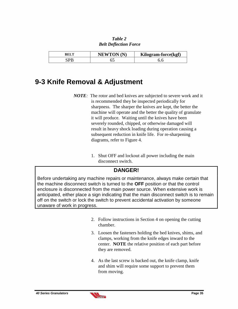
Table 2
Belt Deflection Force
BELT NEWTON (N) Kilogram-force(kgf)
SPB 65 6.6
9-3 Knife Removal & Adjustment
NOTE: The rotor and bed knives are subjected to severe work and it
is recommended they be inspected periodically for
sharpness. The sharper the knives are kept, the better the
machine will operate and the better the quality of granulate
it will produce. Waiting until the knives have been
severely rounded, chipped, or otherwise damaged will
result in heavy shock loading during operation causing a
subsequent reduction in knife life. For re-sharpening
diagrams, refer to Figure 4.
1. Shut OFF and lockout all power including the main
disconnect switch.
DANGER!
Before undertaking any machine repairs or maintenance, always make certain that
the machine disconnect switch is turned to the OFF position or that the control enclosure is disconnected from the main power source. When extensive work is anticipated, either place a sign indicating that the main disconnect switch is to remain off on the switch or lock the switch to prevent accidental activation by someone unaware of work in progress.
2. Follow instructions in Section 4 on opening the cutting
chamber.
3. Loosen the fasteners holding the bed knives, shims, and
clamps, working from the knife edges inward to the
center. NOTE the relative position of each part before
they are removed.
4. As the last screw is backed out, the knife clamp, knife
and shim will require some support to prevent them
from moving.

Page 36 40 Series Granulators
5. Clean the bed knife seats thoroughly with a scraper
and/or emery paper to remove any foreign material and
rust.
6. Inspect the components and replace or resharpen as
required.
9-4 Rotor Knife Removal
1. Carefully lock the rotor with locking pins to prevent it
from turning.
2. Loosen the hex head rotor knife bolts and carefully
remove all rotor knives.
3. Clean the rotor knife seats thoroughly with a scraper
and/or emery paper to remove any foreign material or
rust.
4. Inspect the knives and replace or resharpen as required.
9-5 Rotor Knife Sharpening
The rotor knives must be sharpened to within 0.05 mm of
each other. Greater dimensional variations prevent the
proper setting of the knife gap and may create other serious
complications.
Grinding the cutting edge until it is free of nicks can be
wasteful. It is not harmful to allow small nicks to remain in
the cutting edge.
WARNING!
Do not install rotor knives that are smaller than the minimum dimension shown, because the fasteners that secure these knives may interfere with the cutting circle. The rotor will not be able to rotate and the knives will be damaged. It is important to note that the minimum dimensions given for the rotor knife and bed knife cannot be combined simultaneously to produce a cutting combination.
NOTE: Replacement knife sets and knife re-sharpening services are
available from Cumberland Europe Ltd. Contact the
Customer Service Department at +44 (0)1453 768980.

40 Series Granulators Page 37
Figure 3
Rotor Knife Sharpening
9-6 Rotor Knife Installation
1. Lock the rotor with the rotor restraint pin provided to
prevent it from turning.
2. Re-install the rotor knives onto the rotor. Do not torque
the hex head rotor knife bolts fully at this point -- snug
them down only.
CAUTION!
New or re-sharpened knives should be handled with extreme care. It is
suggested that the sharp cutting edge be covered with tape to prevent damage
to the knives or injury to personnel during installation.
3. Check that the heel of the rotor knife is tight up against
the knife seat. Utilizing a 0.05mm feeler gauge, try to
insert it between the heel of the knife and the knife seat
at both ends and across the rotor knife. If the feeler
gauge will not go down between the heel of the knife
and the knife seat, the knife is installed correctly.
4. Torque down the rotor bolts. Start from the center of
the knife and torque down the bolts equally, working

Page 38 40 Series Granulators
towards the ends of the knife. Refer to Section 9-11 for
the correct torque values based upon bolt sizes and
thread pitch. After the bolts on each knife have been
fully torqued, re-check with a 0.05mm feeler gauge
between the knife and seat. Use the same procedure on
all remaining rotor knives.
9-7 Bed Knife Sharpening
Each bed knife is provided with two (2) cutting edges.
When the exposed edges become blunt, the knives can
be turned over and repositioned to present the new
cutting edges.
It is not necessary to grind bed knives to the closely
matched tolerance of the rotor knives and as with the
rotor knives small nicks in the cutting edges will not
seriously affect knife cutting efficiency. Bed knives
smaller than the minimum dimension shown must be
replaced along with their fasteners.
It is important to note that the minimum dimensions
given for the rotor knife and bed knife cannot be
combined simultaneously to produce a cutting
combination.
NOTE: Replacement knife sets and knife re-sharpening services
are available from Cumberland Europe Ltd. Contact
the Customer Service Department at +44 (0)1453
768980.

40 Series Granulators Page 39
Figure 5
Bed Knife Sharpening
9-8 Bed Knife Installation & Setting
1. Install the new or re-sharpened bed knives, and clamps
in the reverse of removal. Make sure the knives are
fully back against the knife adjusting screws and loosen
the adjusting screw checknuts slightly. Do not torque
the hex head cap screws fully at this point -- snug them
down only.
CAUTION!
New or resharpened knives should be handled with extreme care. It is
suggested that the sharp cutting edge be covered with tape to prevent damage
to the knives or injury to personnel during installation.
2. Align a rotor knife with the primary bed knife, in the
front of the granulator. With a 0.15mm feeler gauge
between the rotor and bed knife, start to adjust the bed
knife into the rotor knife using the adjusting screw.
Page 40 40 Series Granulators
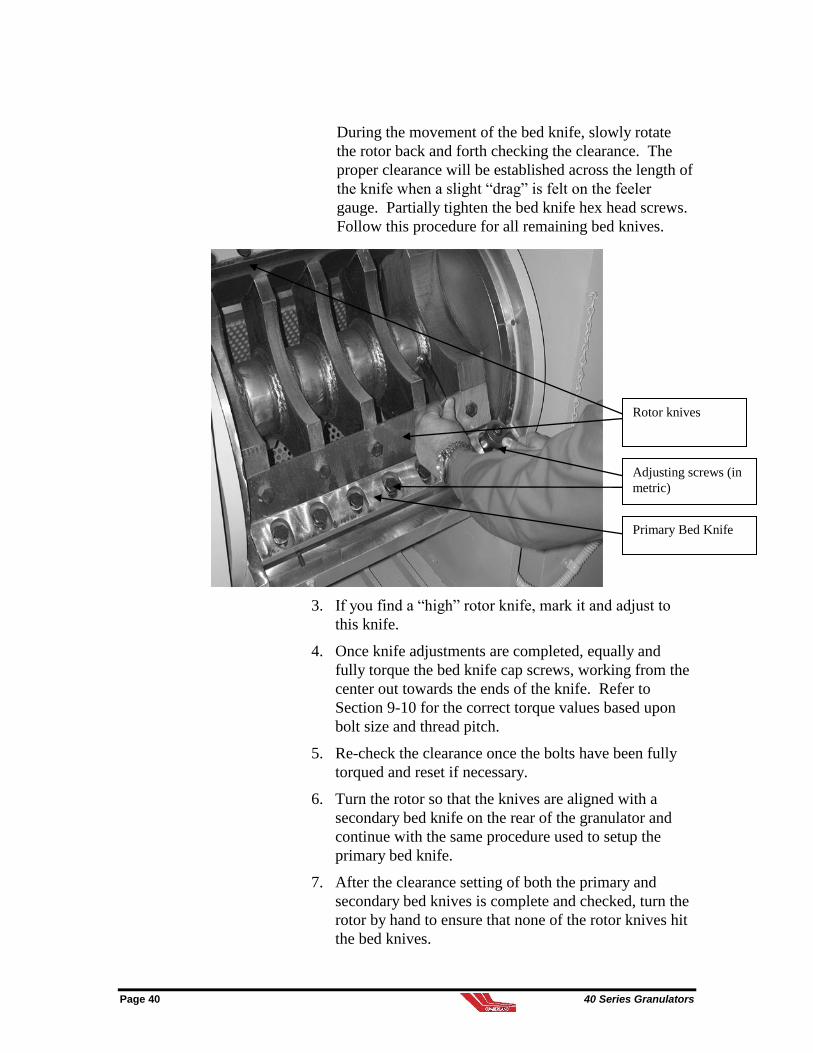
During the movement of the bed knife, slowly rotate
the rotor back and forth checking the clearance. The
proper clearance will be established across the length of
the knife when a slight “drag” is felt on the feeler
gauge. Partially tighten the bed knife hex head screws.
Follow this procedure for all remaining bed knives.
3. If you find a “high” rotor knife, mark it and adjust to
this knife.
4. Once knife adjustments are completed, equally and
fully torque the bed knife cap screws, working from the
center out towards the ends of the knife. Refer to
Section 9-10 for the correct torque values based upon
bolt size and thread pitch.
5. Re-check the clearance once the bolts have been fully
torqued and reset if necessary.
6. Turn the rotor so that the knives are aligned with a
secondary bed knife on the rear of the granulator and
continue with the same procedure used to setup the
primary bed knife.
7. After the clearance setting of both the primary and
secondary bed knives is complete and checked, turn the
rotor by hand to ensure that none of the rotor knives hit
the bed knives.
Adjusting screws (in
metric)
Rotor knives
Primary Bed Knife

40 Series Granulators Page 41
8. Double check inside the machine to make sure no tools
or other articles are left in the cutting chamber or have
fallen into the screen area.
9. Close the cutting chamber and tighten the fasteners
(refer to Section 4-2).
9-9 Preventative Maintenance Service
Follow a systematic preventative maintenance program to
help avoid costly down time. Call the Cumberland Europe
Ltd., Service Department, to arrange a schedule of
inspections. This service can be tailored to fit your
maintenance requirements.
9-10 Recommended Torque For Knife Bolts
NOTE: For Rotor & Bed knife applications, use Grade 10.9 hex
head cap screws.
Table 6
Recommended Bolt Torques (Metric)
METRIC SCREW SIZE TORQUE Nm
(DRY)
M8 38
M10 73
M12 135
M14 210
M16 315
M18 460
M20 640
M24 830
**The above listed torque values are standard specifications.
***Metric Knife Bolt/Screw Tightening Torque for Grade 10.9 Fine Thread

Page 42 40 Series Granulators
10 Troubleshooting
Problem Possible Cause Solution
Motor/(optional) fan motor will not start.
No power.
Verify that the correct pushbuttons are being depressed and that the main disconnect switch is in the ON position.
Fuses are blown.
Try to locate grounds, a locked rotor or other reasons.
Replace fuses with the size and type shown on the wiring diagram (located in the control enclosure).
Check for motor and fan overloads.
Check amperage at electric motors.
If a safety switch is open.
Check the safety switches at the front doors. Ensure proper actuation and replace if required.
If fan is hinged type design (optional)
Check safety limit switch to be sure it is making contact.
After completing above inspection, machine will still not start.
Call Service Department.
Machine stalls/(optional) fan stalls
Machine is overloaded with feedstock.
Reduce amount of feedstock put into machine per unit of time.
Pieces of feedstock jammed in the rotor.
Clear the jammed material then visually inspect the rotor to ensure it is not damaged and that the knife gaps are correct.
40 Series Granulators Page 43
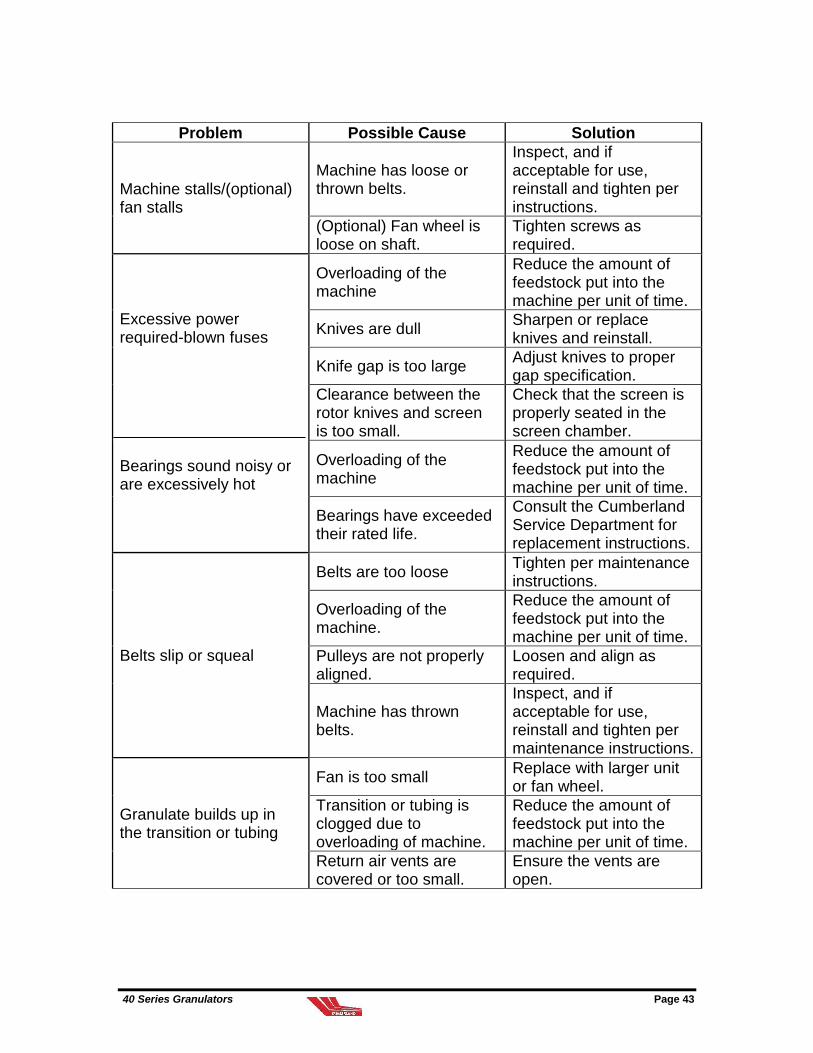
Problem Possible Cause Solution
Machine stalls/(optional) fan stalls
Machine has loose or thrown belts.
Inspect, and if acceptable for use, reinstall and tighten per instructions.
(Optional) Fan wheel is loose on shaft.
Tighten screws as required.
Excessive power required-blown fuses Bearings sound noisy or are excessively hot
Overloading of the machine
Reduce the amount of feedstock put into the machine per unit of time.
Knives are dull Sharpen or replace knives and reinstall.
Knife gap is too large Adjust knives to proper gap specification.
Clearance between the rotor knives and screen is too small.
Check that the screen is properly seated in the screen chamber.
Overloading of the machine
Reduce the amount of feedstock put into the machine per unit of time.
Bearings have exceeded their rated life.
Consult the Cumberland Service Department for replacement instructions.
Belts slip or squeal
Belts are too loose Tighten per maintenance instructions.
Overloading of the machine.
Reduce the amount of feedstock put into the machine per unit of time.
Pulleys are not properly aligned.
Loosen and align as required.
Machine has thrown belts.
Inspect, and if acceptable for use, reinstall and tighten per maintenance instructions.
Granulate builds up in the transition or tubing
Fan is too small Replace with larger unit or fan wheel.
Transition or tubing is clogged due to overloading of machine.
Reduce the amount of feedstock put into the machine per unit of time.
Return air vents are covered or too small.
Ensure the vents are open.
Page 44 40 Series Granulators
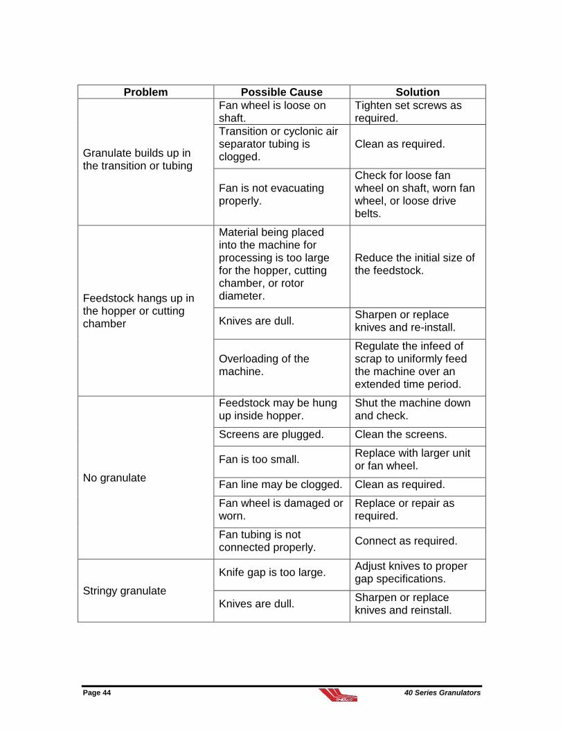
Problem Possible Cause Solution
Granulate builds up in the transition or tubing
Fan wheel is loose on shaft.
Tighten set screws as required.
Transition or cyclonic air separator tubing is clogged.
Clean as required.
Fan is not evacuating properly.
Check for loose fan wheel on shaft, worn fan wheel, or loose drive belts.
Feedstock hangs up in the hopper or cutting chamber
Material being placed into the machine for processing is too large for the hopper, cutting chamber, or rotor diameter.
Reduce the initial size of the feedstock.
Knives are dull. Sharpen or replace knives and re-install.
Overloading of the machine.
Regulate the infeed of scrap to uniformly feed the machine over an extended time period.
No granulate
Feedstock may be hung up inside hopper.
Shut the machine down and check.
Screens are plugged. Clean the screens.
Fan is too small. Replace with larger unit or fan wheel.
Fan line may be clogged. Clean as required.
Fan wheel is damaged or worn.
Replace or repair as required.
Fan tubing is not connected properly.
Connect as required.
Stringy granulate
Knife gap is too large. Adjust knives to proper gap specifications.
Knives are dull. Sharpen or replace knives and reinstall.

40 Series Granulators Page 45
Overloading of feedstock. Reduce the amount of feedstock put into the machine per unit of time.
Problem Possible Cause Solution
Fines
Knives are dull. Sharpen knives (refer to Section 9) and re-install.
Plastic is clogging the screens or transition, preventing proper fan evacuation.
Shut the machine down and clean.
Rotor speed is too fast. Change the pulleys.
Screen size is too small. Change to a screen with larger holes.
Page 46 40 Series Granulators
12 Spare Parts
12-1 Recommended Spare Parts
In order to reduce the amount of down time required to
service a granulator, it is recommended that the following be
kept in stock at your facility:
(1) set of rotor knives and bolts
(1) set of bed knives and bolts
(1) screen or set of screens, (depending if your model
requires multiple screens)
(1) set of belts
(1) set of fuses
(1) set of motor starter heaters
(1) cyclone filter bag (optional)
12-2 Additional Parts
If additional spare parts are required for your granulator,
please consult the Cumberland Spare Parts Department. The
serial numbers of the specific components will be required
when ordering parts from Cumberland.
NOTE: Refer to part numbers in the spare parts catalog when
ordering replacement parts. Check the parts carefully as
knives and screens generally have their numbers etched or
stamped on them. The serial number of the machine will
be required when ordering parts from Cumberland. This
listing of recommended parts does not include all parts,
which are available for purchase. The Cumberland Parts
Department can be reached via +44 (0)1453 768980.

40 Series Granulators Page 47
Service Notes

Page 48 40 Series Granulators
Service Notes