Embed Size (px)
Citation preview

COD: N40.000.EN.2008
USE AND MAINTENANCE MANUAL SPARES CATALOGUE
Mod. G40-50 / G40-70 / G40-90
PLASTIC SYSTEMS S.p.A. Via G. M - 35010 Borgoricco (PD) Italia
Tel. (39) (049) 9335901 - Fax (39) (049) 9335905 e-mail: [email protected]://www.plasticsystems.it
GRANULATORS "SERIES G..."

MANUFACTURER: PLASTIC SYSTEMS S.p.A.
ADDRESS: Via G. Marconi, 6 - 35010 Borgoricco (PD) Italia
Tel. (39) (049) 9335901 - Fax (39) (049) 9335905
e-mail: [email protected]://www.plasticsystems.it
DOCUMENT CODE: N40.000.EN.2008
EDITION: 00.02.2008
PRODUCT: GRANULATORS “SERIES G40”
MODEL: Mod. G40-50 / G40-70 / G40-90
CONFORMITY:

USE AND MAINTENANCE MANUAL SPARE PARTS LIST
"SERIES G40"
GRANULATORS
Mod. G40-50 / Mod. G40-70 / Mod. G40-90
MACHINE TYPE: ...............................................................
SERIAL NUMBER: ...............................................................
YEAR OF MANUFACTURE: ...............................................................
TOTAL WEIGHT: ...............................................................
ELECTRICAL FEATURES: VOLTS............;Hz ...............;PH ............
ELECTRICAL DIAGRAM: ...............................................................
MAX ROTOR R.P.M.: ...............................................................
MOTOR SERIAL NO.: ...............................................................
KW.............;AMPS .......... ;R.P.M. ..........
TOTAL KW: ............................................................... MANUFACTURES PLASTIC SYSTEMS S.p.A. Via G. Marconi 6 - 35010 Borgoricco (PD) Italia Tel. (39) (049) 9335901 - Fax (39) (049) 9335905 e-mail: [email protected]://www.plasticsystems.it

1 - GENERAL INFORMATION N40/Rev. 00.02.08 EN
1 - 1
INDEX
1.1 WARRANTY....................................................................................................................2
1.2 PREPARATORY WORK TO BE PERFORMED BY THE CUSTOMER ..........................2
1.3 REFERENCE STANDARDS ...........................................................................................3
1.4 APPLICABLE DIRECTIVES............................................................................................3
1.5 GLOSSARY.....................................................................................................................4

EN 1 - GENERAL INFORMATION N40/Rev. 00.02.08
1 - 2
1.1 WARRANTY
PLASTIC SYSTEMS S.p.A. granulators are covered by WARRANTY for a period of twelve months, limited to the quality of materials and freedom from manufacturing defects or faulty parts only, as provided for in the general terms and conditions of sale. The warranty also excludes all electrical components, damage due to dropping, tampering or incorrect operation of the granulator, failure to observe the maintenance prescriptions stated in the instruction manual and incorrect manoeuvres by the operator. No compensation shall be payable for any downtime of the granulator. If, during the warranty period, malfunctions or faults of parts of the granulator occur which fall within the cases stated in the warranty, PLASTIC SYSTEMS S.p.A. shall, after appropriate checks, repair or replace the faulty parts, which must first be returned to the manufacturer by the customer. PLASTIC SYSTEMS S.p.A. accepts responsibility for the granulator in its original configuration. Any work which changes the configuration or functioning of the granulator must be executed by or, in any event, authorized by PLASTIC SYSTEMS S.p.A. 's Engineering Department. PLASTIC SYSTEMS S.p.A. declines all liability for damage or malfunctioning of the granulator caused by unauthorized modifications or tampering. The WARRANTY shall also lapse when non-original spares or spares other than those explicitly designated as 'SAFETY COMPONENTS' by PLASTIC SYSTEMS S.p.A. in this manual are used. For all the above reasons, we advise our customers to consult our Assistance Service for their servicing requirements. 1.2 PREPARATORY WORK TO BE PERFORMED BY THE CUSTOMER
With the exception of any specific agreements stipulated in the terms of the contract of sale, the following are normally the responsibility of the customer: - provision of a power supply; - protective earth wire, if the machine is equipped with a granule transport system with suction
fan; - tools and consumables; - the lubricants required for operation and maintenance of the machine;
1 - GENERAL INFORMATION N40/Rev. 00.02.08 EN
1 - 3
1.3 REFERENCE STANDARDS
- EN 292 - 1. Basic design principles - Part 1: Terminology and basic methods. - EN 292 - 2. Basic design principles - Part 2: Technical principles and specifications. - EN 294. Safety distances to prevent access to danger zones with upper limbs. - EN 418. Emergency stopping devices: functional aspects and design principles. - EN 953. General requisites for the design and construction of machine guards: fixed and
moveable guards. - UNI ISO 1219. Hydraulic and pneumatic power transmission - Technical drawings and product
technical documentation. - UNI 7543. Safety colours and signs. - EN 60204 - 1. Machine safety. Machine electrical equipment - Part 1: General rules (CEI 44 -
5). - EN 60947 - 3. Low voltage apparatus - Part 3: General control breakers, isolator breakers,
control breakers - isolator switches and combined units with fuses (CEI 17 - 11). - EN 12012 - 1. Rubber and plastics machines - Size Reduction machines - Part. 1: Safety
requirements for blade granulators. 1.4 APPLICABLE DIRECTIVES
- Directive 89/654/EEC. Relative to workplaces. Implemented in Italy with Decree Law n° 626/1994 - Title II.
- Machinery directive 98/37/CE. - Directive 2006/95/EEC. Concerning the safety of electrical materials utilized in "low voltage". - Directive 89/336/EEC. Concerning electromagnetic compatibility. - Directive 86/188/EEC. Risks deriving from exposure to noise. Implemented in Italy with Decree
Law n° 277/1991.
EN 1 - GENERAL INFORMATION N40/Rev. 00.02.08
1 - 4
1.5 GLOSSARY
OPERATOR: Person appointed to install, run, adjust, maintain, clean, repair and transport the granulator. HAZARDOUS AREA: Area within and/or near the granulator where an exposed person's health and safety are at risk. EXPOSED PERSON: Any person wholly or partly in a hazardous area. RESIDUAL HAZARD: Hazard which could not be eliminated or reduced sufficiently by design, against which protection is not (or not fully) effective. The manual gives information on the presence of such hazards and instructions and warnings on overcoming them. SAFETY COMPONENT: A component used to fulfil a safety function, failure or malfunctioning of which jeopardises the health or safety of exposed persons (e.g. a fixed, mobile or adjustable guard, etc., an electric, electronic, visual, pneumatic or hydraulic device which monitors, i.e. interlocks with, a protective device, etc.). BLADE GRANULATOR: machine that cuts material in a cutting/reduction chamber, reducing its sizes until it is able to enter the oufeed zone through the calibrated holes in a specifically designed screen. CUTTING CHAMBER: area of the machine where the material is cut. ROTOR: rotary cutter on which the blades are fixed in the cutting chamber. FIXED BLADES: single or multiple blades fixed inside the cutting chamber. FEEDING AREA: area in which the stock to be granulated is placed. FEEDING SYSTEM: the part of the machine utilized to insert the material in the cutting chamber. The feeding system can either be fixed (e.g. a hopper) or mobile (e.g. rollers, screw feeder, conveyor belts or pneumatic conveyors).
1 - GENERAL INFORMATION N40/Rev. 00.02.08 EN
1 - 5
ROTOR MECHANICAL LOCK: device that prevents the rotor from being turned manually or from turning to inertia during the granulator stopping phase and when the cutting chamber is open because of maintenance operation. OUTFEED AREA: area where the finished product or "regrind" leaves the cutting chamber. SCREEN: sheet metal screen located in the cutting chamber outfeed zone where it serves to allow the transit of granules only of the required dimensions. WORKING LEVEL: surface on which the person responsible for feeding the granulator stands. CRADLE: mobile assembly that supports the screens. HOPPER: mobile assembly with inclined walls responsible for keeping the cutting chamber supplied with raw material.

EN 1 - GENERAL INFORMATION N40/Rev. 00.02.08
1 - 6

2 - DESCRIPTION OF THE MACHINE AND TECHNICAL SPECIFICATIONS N40/Rev. 00.02.08 EN
2 - 1
INDEX
2.1 DESCRIPTION OF GRANULATOR ................................................................................2
2.2 TECHNICAL FEATURES................................................................................................3
2.3 MAIN COMPONENTS OF STANDARD GRANULATOR ................................................4
2.3.1 Accessories on request ...................................................................................................4
2.4 OVERALL DIMENSIONS ................................................................................................5
2.5 PERMITTED ENVIRONMENTAL CONDITIONS ............................................................6
2.6 OPERATING CLEARANCES ..........................................................................................6
EN 2 - DESCRIPTION OF THE MACHINE AND TECHNICAL SPECIFICATIONS N40/Rev. 00.02.08
2 - 2
2.1 DESCRIPTION OF GRANULATOR
This family of granulators has been designed for effective granulation of plastic and rubber of various sizes. The granulator consists of a loading hopper (in which material for grinding is placed) connected to a cutting chamber where a series of rotating and fixed blades reduce it to granules, the size of which is determined by the holes in the grille. These granules drop down to the collection box.
NOTE If required, the collection box can be replaced with a “granule extraction cone”
controlled by a powerful suction system or (alternatively) by a screw-type mechanic conveyor system that outlets them.
2 - DESCRIPTION OF THE MACHINE AND TECHNICAL SPECIFICATIONS N40/Rev. 00.02.08 EN
2 - 3
2.2 TECHNICAL FEATURES
Common features: Feed: Frontal Feeding Hopper: Hinged with manual tipping possibility. Rotor diameter: mm 420 Rotor speed: rev/1' 460 Grille holes diameter (standard): mm 8 Features specific to Mod. N40-50 • Rotating blades: n° 3 • Fixed blades: n° 2 • Feeding inlet dimensions: mm 515x502 • Transmission belts: n° 3 • Motor power: kW 15 • Complete GRANULATOR weight: kg 1300 Features specific to Mod. N40-70 • Rotating blades: n° 3 + 3 • Fixed blades: n° 2 + 2 • Feeding inlet dimensions: mm 712x502 • Transmission belts: n° 4 • Motor power: kW 22 • Complete GRANULATOR weight: kg 1600 Features specific to Mod. N40-90 • Rotating blades: n° 3 + 3 • Fixed blades: n° 2 + 2 • Feeding inlet dimensions: mm 915x502 • Transmission belts: n° 5 • Motor power: kW 30 • Complete GRANULATOR weight: kg 1900
EN 2 - DESCRIPTION OF THE MACHINE AND TECHNICAL SPECIFICATIONS N40/Rev. 00.02.08
2 - 4
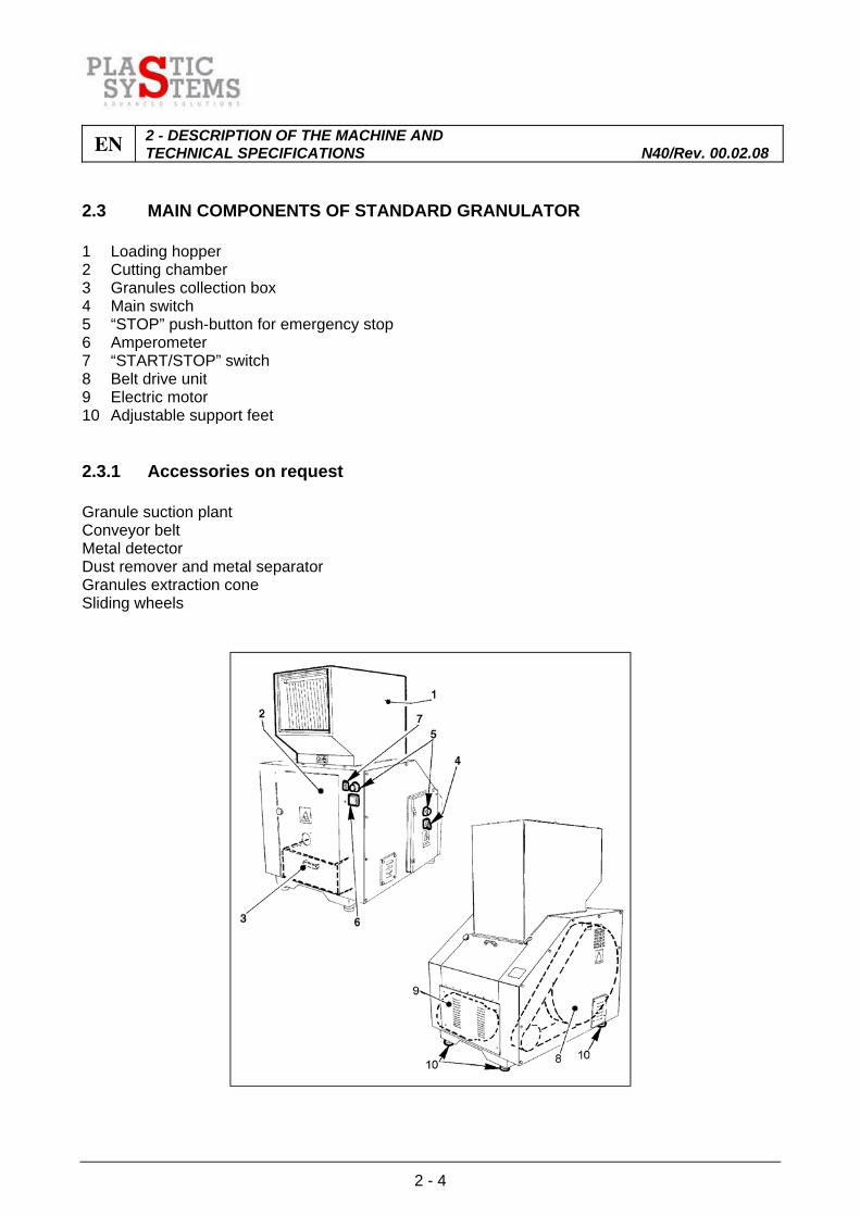
2.3 MAIN COMPONENTS OF STANDARD GRANULATOR
1 Loading hopper 2 Cutting chamber 3 Granules collection box 4 Main switch 5 “STOP” push-button for emergency stop 6 Amperometer 7 “START/STOP” switch 8 Belt drive unit 9 Electric motor 10 Adjustable support feet 2.3.1 Accessories on request
Granule suction plant Conveyor belt Metal detector Dust remover and metal separator Granules extraction cone Sliding wheels
2 - DESCRIPTION OF THE MACHINE AND TECHNICAL SPECIFICATIONS N40/Rev. 00.02.08 EN
2 - 5
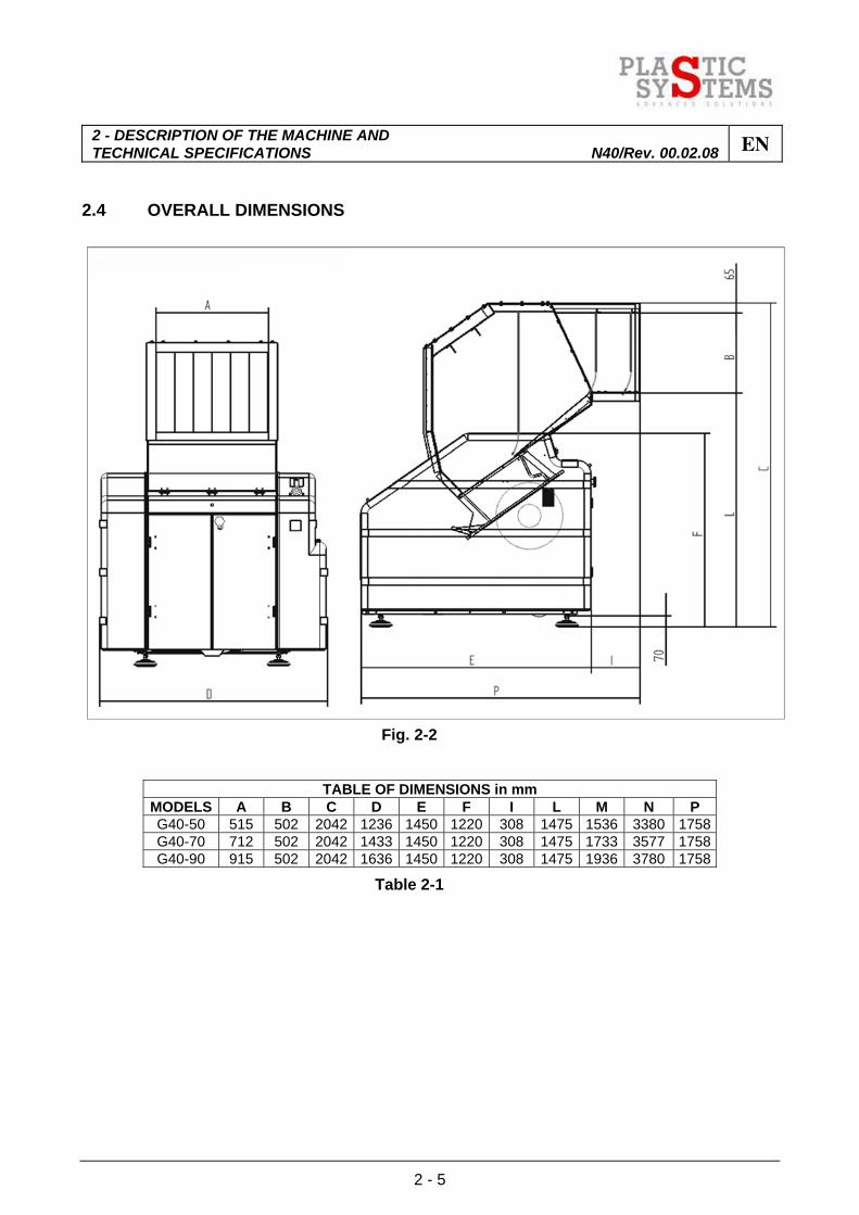
2.4 OVERALL DIMENSIONS
Fig. 2-2
TABLE OF DIMENSIONS in mm MODELS A B C D E F I L M N P G40-50 515 502 2042 1236 1450 1220 308 1475 1536 3380 1758G40-70 712 502 2042 1433 1450 1220 308 1475 1733 3577 1758G40-90 915 502 2042 1636 1450 1220 308 1475 1936 3780 1758
Table 2-1
EN 2 - DESCRIPTION OF THE MACHINE AND TECHNICAL SPECIFICATIONS N40/Rev. 00.02.08
2 - 6
2.5 PERMITTED ENVIRONMENTAL CONDITIONS
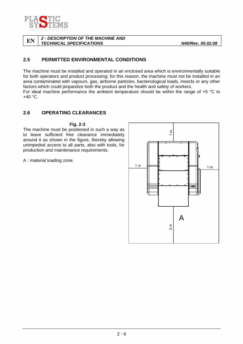
The machine must be installed and operated in an enclosed area which is environmentally suitable for both operators and product processing; for this reason, the machine must not be installed in an area contaminated with vapours, gas, airborne particles, bacteriological loads, insects or any other factors which could jeopardize both the product and the health and safety of workers. For ideal machine performance the ambient temperature should be within the range of +5 °C to +40 °C. 2.6 OPERATING CLEARANCES
Fig. 2-3 The machine must be positioned in such a way as to leave sufficient free clearance immediately around it as shown in the figure, thereby allowing unimpeded access to all parts, also with tools, for production and maintenance requirements. A : material loading zone.

3 - SAFETY AND ACCIDENT PREVENTION N40/Rev. 00.02.08 EN
3 - 1
INDEX
3.1 GENERAL STANDARDS ................................................................................................2
3.2 INTENDED USE, UNINTENDED USE AND IMPROPER USE.......................................4
3.2.1 Intended use....................................................................................................................4
3.2.2 Unintended use ...............................................................................................................4
3.3 SAFETY DEVICES..........................................................................................................5
3.4 SAFETY DEVICES INSTALLED ON GRANULATOR.....................................................5
3.5 SOUND CHARACTERISTICS OF GRANULATOR: NOISE LEVEL GENERATED ..................................................................................................................8
3.5.1 Series G40 granulator noise test .....................................................................................8
3.5.2 Noise levels generated: background regulations and Test methods..............................8
3.6 IDENTIFICATION AND CERTIFICATION PLATE ........................................................10
3.7 PLATES ON GRANULATOR ........................................................................................11
3.8 COMMAND AND CONTROL ZONES AND DANGER ZONES.....................................12
3.9 RESIDUAL RISKS AND HAZARDS ..............................................................................13
3.9.1 Residual cutting hazard.................................................................................................13
3.9.2 Residual risk due to noise .............................................................................................13
3.9.3 Residual risk caused by jamming of the rotor ...............................................................13

EN 3 - SAFETY AND ACCIDENT PREVENTION N40/Rev. 00.02.08
3 - 2
3.1 GENERAL STANDARDS
PLASTIC SYSTEMS S.p.A. has lavished the utmost care in designing this family of granulators and making them as safe as possible. It has also equipped them with all the safety devices and protection deemed necessary. Finally it has provided them with sufficient information for safe, correct use. In accordance with the ‘Workplace Lighting’ requirements, the premises accommodating the granulator shall have no areas of shade, tiresome dazzle or hazardous stroboscope effects due to the lighting at the workplace. Ideal ventilation of the premises shall also be guaranteed, with appropriate use of proper extraction plant if provided. The granulator shall be used only by QUALIFIED OPERATORS and is built to granulate PLASTICS. Materials other than those stated may only be used by written permission of PLASTIC SYSTEMS S.p.A.. Lack of such permission shall exonerate the manufacturer from any liability whatsoever for possible damage to the granulator, objects, persons and animals. Operating, maintenance, cleaning and inspecting staff etc. shall act in strict compliance with the accident prevention standards of the country of destination of the granulator. The operator is advised to wear suitable clothing for the respective working environment and situation. The person assigned to the granulator or its maintenance is asked to pay careful attention to the clothing worn, e.g.: - Avoid wearing clothes with parts which may become trapped in parts of the granulator; - Avoid wearing scarves or other loose items of clothing; - Avoid wearing cumbersome rings or bracelets which may trap hands in parts of the granulator. Before starting work the operator shall be fully aware of the positions and functioning of all controls and features of the granulator.
NOTE SEE SECTION 0.4 FOR EXACT OPERATOR QUALIFICATIONS Paragraph 1.5 ‘Glossary’ defines various terms used in this paragraph. Ordinary and extraordinary maintenance and cleaning shall take place with the granulator at a standstill and disconnected from the electricity supply. When making the electric connections, it is sound practice to comply with the general rules of installation and connection; these operations shall be carried out by qualified staff. Do not modify parts of the granulator for any reason. In case of malfunction due to breach of this requirement, PLASTIC SYSTEMS S.p.A. will not be answerable for the consequences. We advise making written requests for any modifications direct to the manufacturer.

3 - SAFETY AND ACCIDENT PREVENTION N40/Rev. 00.02.08 EN
3 - 3
Clean the granulator coverings, panels and controls with soft cloths, either dry or dipped in a mild detergent solution. Do not use any solvent such as alcohol or benzene which might damage the surfaces.
N.B. Qualified staff are defined as those who have followed specialisation and training courses etc. and who have experience of granulator installation, start-up and maintenance.

EN 3 - SAFETY AND ACCIDENT PREVENTION N40/Rev. 00.02.08
3 - 4
3.2 INTENDED USE, UNINTENDED USE AND IMPROPER USE
3.2.1 Intended use
The machine described in this manual is designed for the granulation of the plastic and rubber materials stated in the terms of the contract and within the prescribed limits. 3.2.2 Unintended use
The use of the granulator for processing materials that are not specified in the terms of the contact, or to obtain results that are outside the prescribed capabilities of the machine, are construed as "UNINTENDED USE" and therefore constitute "IMPROPER" use of the machine.
ATTENTION The machine must not be used to process flammable, explosive, toxic/noxious,
ferrous materials or materials that develop any of the foregoing characteristics when subjected to processing.
The machine is not designed for use in explosive atmospheres and it must not therefore be installed in places subject to the presence of explosive atmospheres.
PLASTIC SYSTEMS S.p.A. declines all liability for damage that may be caused to property or injury to persons resulting from improper use of the machine, and in such circumstances shall also consider the warranty to be completely invalidated.
3 - SAFETY AND ACCIDENT PREVENTION N40/Rev. 00.02.08 EN
3 - 5
3.3 SAFETY DEVICES
Granulators are provided with safety devices to protect workers and the granulator itself. The user is therefore warned not to remove or tamper with such devices. 3.4 SAFETY DEVICES INSTALLED ON GRANULATOR
All moving parts are enclosed by protective cases which cannot be removed without specific equipment and, moreover, cannot remain in their proper positions without fastening attachments.
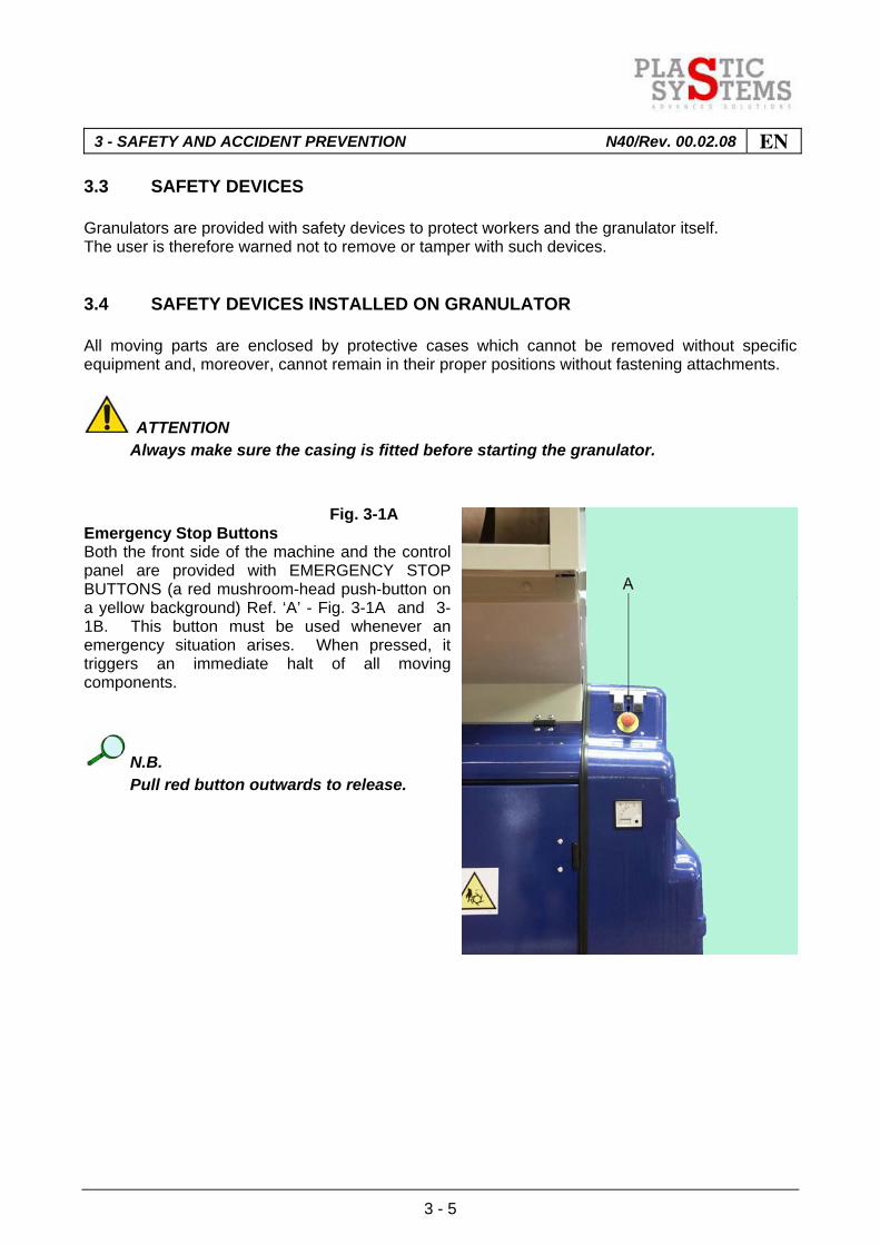
ATTENTION Always make sure the casing is fitted before starting the granulator. Fig. 3-1A Emergency Stop Buttons Both the front side of the machine and the control panel are provided with EMERGENCY STOP BUTTONS (a red mushroom-head push-button on a yellow background) Ref. ‘A’ - Fig. 3-1A and 3-1B. This button must be used whenever an emergency situation arises. When pressed, it triggers an immediate halt of all moving components.
N.B. Pull red button outwards to release.

EN 3 - SAFETY AND ACCIDENT PREVENTION N40/Rev. 00.02.08
3 - 6
Fig. 3-1B The machine only resets after "RESET" button is pressed. The top of the cutting chamber is protected by the hopper which feeds material for grinding, while the bottom is enclosed in the machine structure.
Fig. 3-2 Front panel opening electromagnetic safety switch The cutting chamber is accessible by opening the front panel, the catch of which is controlled by an electromagnetic safety switch Ref ‘D’ - Fig. 3-2. When released, this triggers a halt of the machine. About 30 seconds after rotor has come to a complete halt, the rotation sensor sends a pulse to the ELECTROMAGNETIC SWITCH which releases the front door; at this point the front panel can be opened unscrewing completely the knob Ref. "C" - Fig. 3-2.
ATTENTION The electromagnetic safety switch releases and opens the front panel only if the
granulator has already been connected to the supply mains and the MAIN SWITCH, Ref. “E” Fig. 3-1B, is in Pos. "ON".
IMPORTANT Before releasing the front opening, check that the emergency push-buttons are
disabled. To reset, close the front panel, screw up the knob, then press Reset button.

3 - SAFETY AND ACCIDENT PREVENTION N40/Rev. 00.02.08 EN
3 - 7
Rear panel opening safety microswitch Fig. 3-3A The safety microswitch on the rear panel is controlled by a plate, Ref. "E" - Fig. 3-3A, which is integral with the panel. When the panel is closed, the plate presses against a screw, Ref. "F" - Fig. 3-3A, that activates the microswitch; opening the panel serves to deactivate safety microswitch "G" - Fig. 3-3B, which disconnects the power supply to the motor causing the rotor to stop. To reset, close the panel so that the plate operates the safety microswitch and then press the Reset button. Fig. 3-3B

EN 3 - SAFETY AND ACCIDENT PREVENTION N40/Rev. 00.02.08
3 - 8
3.5 SOUND CHARACTERISTICS OF GRANULATOR: NOISE LEVEL GENERATED
Noise tests were performed by the ENGINEERING OFFICE OF VALERIO TARABUSI, ASSOCIATED PROFESSOR OF ENGINEERING PHYSICS AT THE FACULTY OF ENGINEERING, BOLOGNA. 3.5.1 Series G40 granulator noise test
Research has been conducted to assess the noise generated by the operation of Granulators Models G40-50, G40-70, G40-90 standard version and suction fan version, manufactured by PLASTIC SYSTEMS S.p.A.. - Borgoricco (Padova). 3.5.2 Noise levels generated: background regulations and Test methods
Reference was made to the following technical regulations to establish the noise emitted by the machine: S.P.I. NOISE TEST - Noise Measurement Procedure for Granulators, by Society of the Plastic Industry. UNI 7712 - Machine Tools - Determining Noise in the Working Environment - 1977 ISO 3746 - Acoustics - Determination of sound power level of noise sources - Engineering method for free field conditions over a reflecting plane - 1981. ISO 3746 - Acoustics - Determination of sound power level of noise sources - Survey method - 1979. DIN 45635 - Measurements of airborne noise emitted by machines - Enveloping measuring method - 1972. The technical specifications of the granulator PLASTIC SYSTEMS S.p.A.Mod. G40-50, G40-70, G40-90 standard version and suction fan version and the test methods to establish the noise level generated are described below. The following table gives the mean sound levels Lpm in dB(A) for each model of machine, reckoned as an average of the sound levels measured at the four positions shown on the diagram below.
Motor power
Speed Rotor
Production*
Production at 75%
Test feeding
Model
Version
kW rpm kg/h g/h pieces/min. G40-50 Standard 15,0 460 350 262,5 60 G40-70 Standard 22,0 460 490 367,5 72 G40-90 Standard 30,0 460 630 472,5 86
Table 3-1 (*) Machine equipped with 8 mm holes grid.
3 - SAFETY AND ACCIDENT PREVENTION N40/Rev. 00.02.08 EN
3 - 9
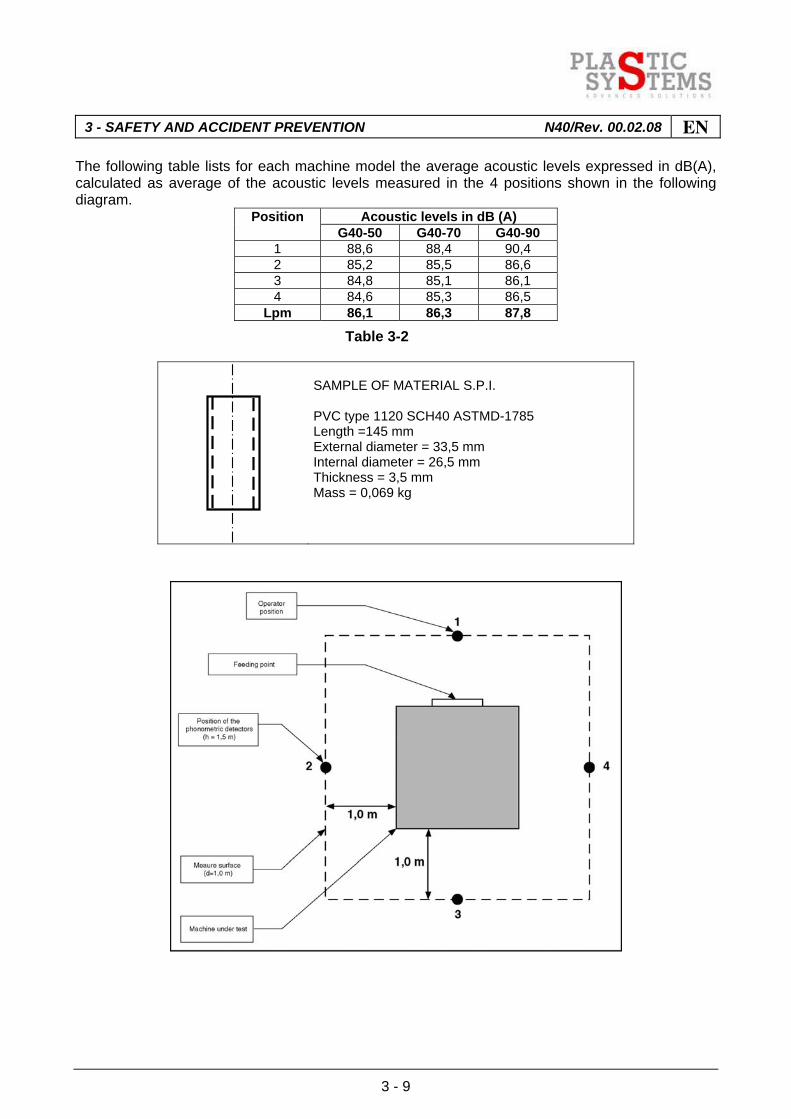
The following table lists for each machine model the average acoustic levels expressed in dB(A), calculated as average of the acoustic levels measured in the 4 positions shown in the following diagram.
Acoustic levels in dB (A) Position G40-50 G40-70 G40-90
1 88,6 88,4 90,4 2 85,2 85,5 86,6 3 84,8 85,1 86,1 4 84,6 85,3 86,5
Lpm 86,1 86,3 87,8
Table 3-2
SAMPLE OF MATERIAL S.P.I. PVC type 1120 SCH40 ASTMD-1785 Length =145 mm External diameter = 33,5 mm Internal diameter = 26,5 mm Thickness = 3,5 mm Mass = 0,069 kg

EN 3 - SAFETY AND ACCIDENT PREVENTION N40/Rev. 00.02.08
3 - 10
3.6 IDENTIFICATION AND CERTIFICATION PLATE
The figure shows the identification plate and its position on the granulator. The model, serial number and year of manufacture stamped on the plate must be quoted when requesting information about the granulator is requested or ordering spares.
Fig. 3-4
3 - SAFETY AND ACCIDENT PREVENTION N40/Rev. 00.02.08 EN
3 - 11
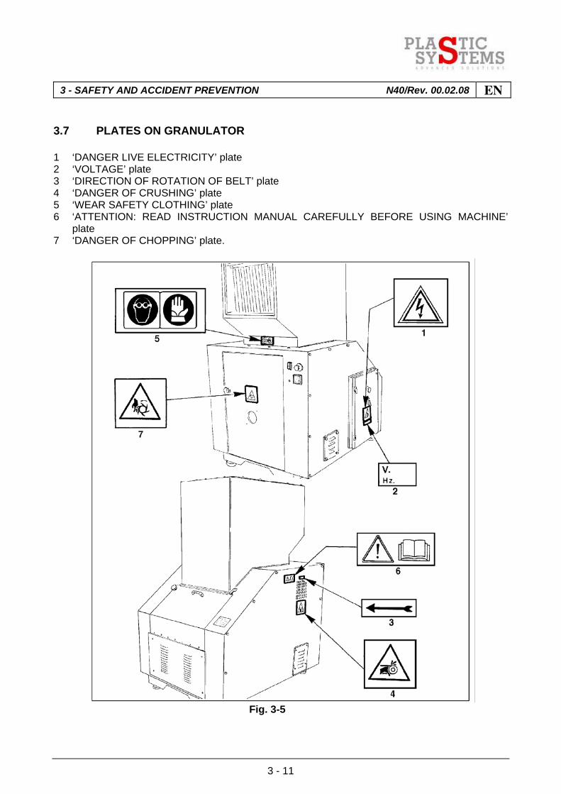
3.7 PLATES ON GRANULATOR
1 ‘DANGER LIVE ELECTRICITY’ plate 2 ‘VOLTAGE’ plate 3 ‘DIRECTION OF ROTATION OF BELT’ plate 4 ‘DANGER OF CRUSHING’ plate 5 ‘WEAR SAFETY CLOTHING’ plate 6 ‘ATTENTION: READ INSTRUCTION MANUAL CAREFULLY BEFORE USING MACHINE’
plate 7 ‘DANGER OF CHOPPING’ plate.
Fig. 3-5
EN 3 - SAFETY AND ACCIDENT PREVENTION N40/Rev. 00.02.08
3 - 12
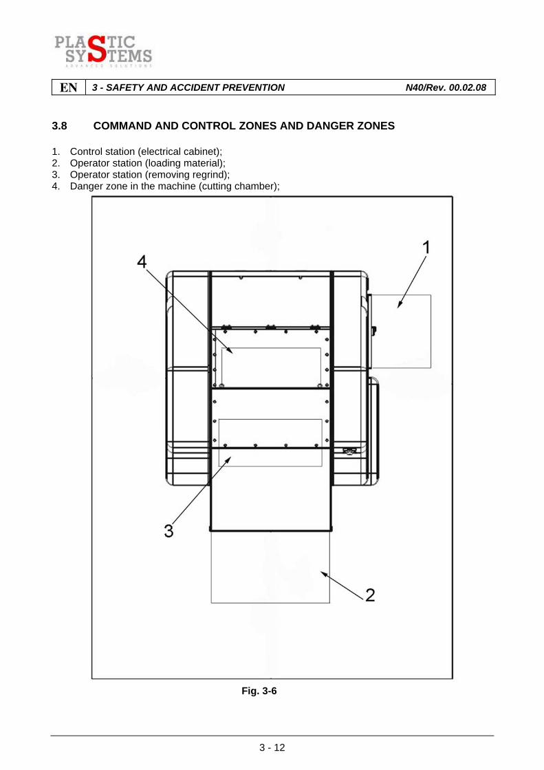
3.8 COMMAND AND CONTROL ZONES AND DANGER ZONES
1. Control station (electrical cabinet); 2. Operator station (loading material); 3. Operator station (removing regrind); 4. Danger zone in the machine (cutting chamber);
Fig. 3-6
3 - SAFETY AND ACCIDENT PREVENTION N40/Rev. 00.02.08 EN
3 - 13
3.9 RESIDUAL RISKS AND HAZARDS
3.9.1 Residual cutting hazard
When handling the blades (maintenance, adjustment, replacement), the sharp edges constitute a cutting hazard.
WARNING The operator must adopt appropriate personal protective equipment, namely cut-
resistant gloves according to the requirements indicated in standard EN 388; the operator must also protect the blade cutting edges with rubber guards.
3.9.2 Residual risk due to noise
Even though the measured sound pressure levels are within the established safety limits, prolonged exposure to the noise of the machine can cause damage to the hearing of operators or other exposed persons. It is therefore recommended to install the machine in a soundproof enclosure, or to equip all exposed persons with relative personal protective equipment such as hearing protectors, safety earmuffs or earplugs.
Important! The clothing worn and the protection devices used must comply with the EEC
Directive 686 concerning personal protective equipment, or alternatively, with statutory regulations in the country of installation of the machine.
3.9.3 Residual risk caused by jamming of the rotor
In the event of rotor jamming caused by a build up of material in the cutting chamber, the operator's action carried out in an attempt to remove the jam could lead to a potentially hazardous situation.
WARNING Do not act impulsively or without thinking. The operator must adhere strictly to the rotor clearing procedure described in
heading 7.10 of this manual.

EN 3 - SAFETY AND ACCIDENT PREVENTION N40/Rev. 00.02.08
3 - 14

4 - INSTALLATION INSTRUCTIONS N40/Rev. 00.02.08 EN
4 - 1
INDEX
4.1 RULES FOR MOVING THE MACHINE...........................................................................2
4.2 TRANSPORT AND INSTALLATION ...............................................................................2
4.3 LIFTING...........................................................................................................................3
4.4 INSTALLATION...............................................................................................................4
4.4.1 Levelling ..........................................................................................................................5
4.5 ELECTRIC CONNECTION..............................................................................................6
EN 4 - INSTALLATION INSTRUCTIONS N40/Rev. 00.02.08
4 - 2
4.1 RULES FOR MOVING THE MACHINE
To lift and move correctly and safely: - Use the equipment with the most suitable features and capacity; - Cover sharp edges. Before proceeding to lift: - Check that there is no material which may fall during the lifting stage. Before positioning the granulator, check that: - The floor is level and strong enough to bear the load; - There is sufficient room in the installation area for movement of products for processing
without obstructing necessary maintenance operations. 4.2 TRANSPORT AND INSTALLATION
The granulator is normally dispatched without packing, protected by a cellophane wrapping and installed on pallet. It is advisable to check for any damaged caused during transport on receipt and immediately notify it to the carrier. Also check that the list of components supplied on the delivery note matches the content of the packing. Together with the granulator, the customer will receive the instruction manual as well.
ATTENTION Before lifting or moving the granulator, check the weight marking on plate attached to
the granulator (see par. 3-6).
4 - INSTALLATION INSTRUCTIONS N40/Rev. 00.02.08 EN
4 - 3
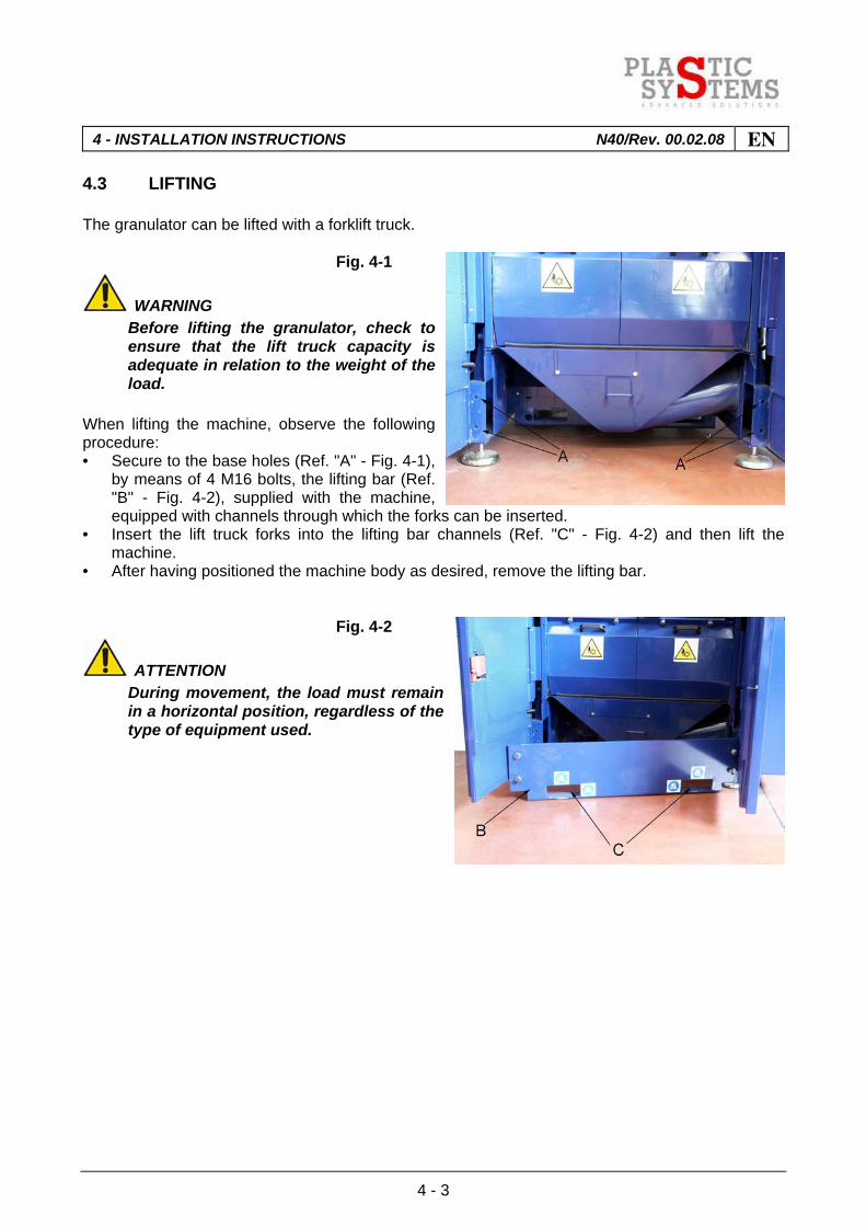
4.3 LIFTING
The granulator can be lifted with a forklift truck. Fig. 4-1
WARNING Before lifting the granulator, check to
ensure that the lift truck capacity is adequate in relation to the weight of the load.
When lifting the machine, observe the following procedure: • Secure to the base holes (Ref. "A" - Fig. 4-1),
by means of 4 M16 bolts, the lifting bar (Ref. "B" - Fig. 4-2), supplied with the machine, equipped with channels through which the forks can be inserted.
• Insert the lift truck forks into the lifting bar channels (Ref. "C" - Fig. 4-2) and then lift the machine.
• After having positioned the machine body as desired, remove the lifting bar. Fig. 4-2
ATTENTION During movement, the load must remain
in a horizontal position, regardless of the type of equipment used.

EN 4 - INSTALLATION INSTRUCTIONS N40/Rev. 00.02.08
4 - 4
4.4 INSTALLATION
IMPORTANT Make sure the base on which the granulator rests is compact, even and perfectly flat
so that it holds the granulator rigidly without the slightest oscillation. The recommended flooring is reinforced concrete with a very smooth support surface.
POSITION GRANULATOR IN A SUFFICIENTLY ROOMY AREA TO LEAVE THE NECESSARY SPACE ON ALL SIDES FOR THE OPERATOR TO CARRY OUT ALL MAINTENANCE OPERATIONS. This granulator is designed to run without water. Although the fitted electric components are designed to EEC regulations, they must operate without moisture or water. We therefore advise installing the granulator in an environment sheltered from the weather and isolated from any water there may be on the ground. Having positioned granulator, disconnect eye-bolts from hooks and close panels in reverse order to opening. Detach control panel from harness used for transport and position alongside the granulator.

4 - INSTALLATION INSTRUCTIONS N40/Rev. 00.02.08 EN
4 - 5
4.4.1 Levelling
Fig. 4-3 The granulator rests on 4 adjustable feet (Ref. ‘A’ - Fig. 4-3) which are used for levelling as follows: • Loosen locking upper and lower nuts "B" -
Fig. 4-4 on each machine foot. • Perform the adjustment on the right and left
sides, causing each foot to slide upwards or downwards as necessary.
• For adjustment of the rear feet lift the machine with a fork lift truck in order to gain access to the locking nuts.
• Tighten locking nuts "B" - Fig. 4-4. • Ensure that the feet are all resting on the
floor.
Fig. 4-4
EN 4 - INSTALLATION INSTRUCTIONS N40/Rev. 00.02.08
4 - 6
4.5 ELECTRIC CONNECTION
N.B. Have this work done by a qualified ‘operator/electrical maintenance technician’. To start the granulator, ensure that the electric power cable is well made and reliable, protected by an automatic line switch and connected to a good earthing system to prevent the machine becoming a dangerous source of electric potential.
ATTENTION Before carrying out this operation, make sure line voltage is as stated on granulator
plate and that master switch (Ref. ‘E’ - Fig. 3-1B) is in the ‘OFF’ position. UNLESS OTHER VOLTAGES ARE REQUESTED AT THE TIME OF ORDERING, THE GRANULATOR WILL ALWAYS BE SUPPLIED FOR 400V 50 Hz.
IMPORTANT Choose a suitable electric cable for the power of the motor installed, bearing in mind
that it may be working 24 hours a day.

4 - INSTALLATION INSTRUCTIONS N40/Rev. 00.02.08 EN
4 - 7
Fig. 4-5 Insert supply cable "B" - Fig. 4-5, into the control panel through the cable inlet at the top left of the panel and then connect the three line conductors (R, S, T) to the appropriate terminals of the main switch and the earth cable at the point shown by the ( ) symbol in Fig. 4-5.

EN 4 - INSTALLATION INSTRUCTIONS N40/Rev. 00.02.08
4 - 8

5 - SET-UP AND FIRST START-UP N40/Rev. 00.02.08 EN
5 - 1
INDEX
5.1 CONTROL AND CHECK EQUIPMENT ..........................................................................2
5.1.1 Control panel ...................................................................................................................2
5.2 PRELIMINARY CHECKS BEFORE START-UP..............................................................3
5.2.1 Checking the cutting chamber.........................................................................................3
5.2.2 Check of granulator rotation direction .............................................................................6
5.2.3 Checking the direction of rotation of the suction fan (if installed) ....................................6
5.2.4 Checking position of fixed blades....................................................................................7
5.2.5 Checking position of rotating blades ...............................................................................8
5.3 OPERATING MODES .....................................................................................................9
5.4 STOP AND EMERGENCY MODES..............................................................................10
5.4.1 Stopping the work cycle ................................................................................................10
5.4.2 Emergency stop ............................................................................................................10
5.4.3 Stop due to electrical power loss...................................................................................10
EN 5 - SET-UP AND FIRST START-UP N40/Rev. 00.02.08
5 - 2
5.1 CONTROL AND CHECK EQUIPMENT
5.1.1 Control panel
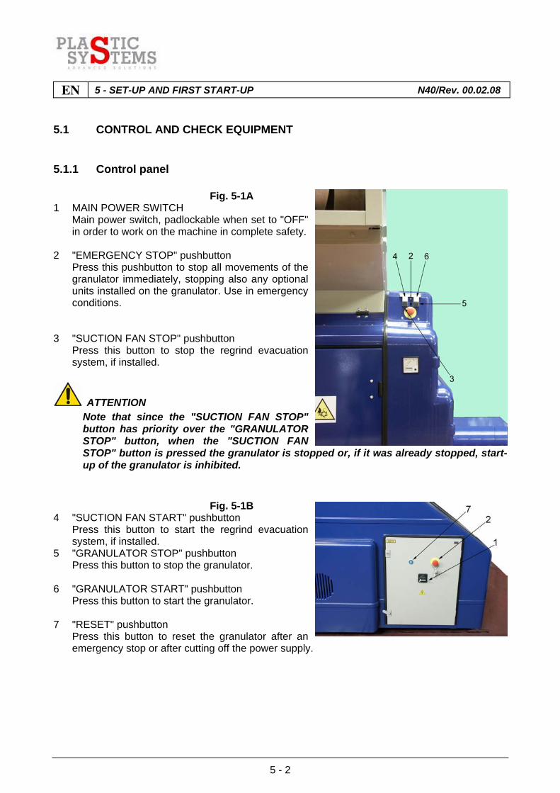
Fig. 5-1A 1 MAIN POWER SWITCH Main power switch, padlockable when set to "OFF"
in order to work on the machine in complete safety. 2 "EMERGENCY STOP" pushbutton Press this pushbutton to stop all movements of the
granulator immediately, stopping also any optional units installed on the granulator. Use in emergency conditions.
3 "SUCTION FAN STOP" pushbutton Press this button to stop the regrind evacuation
system, if installed.
ATTENTION Note that since the "SUCTION FAN STOP"
button has priority over the "GRANULATOR STOP" button, when the "SUCTION FAN STOP" button is pressed the granulator is stopped or, if it was already stopped, start-up of the granulator is inhibited.
Fig. 5-1B 4 "SUCTION FAN START" pushbutton Press this button to start the regrind evacuation
system, if installed. 5 "GRANULATOR STOP" pushbutton Press this button to stop the granulator. 6 "GRANULATOR START" pushbutton Press this button to start the granulator. 7 "RESET" pushbutton Press this button to reset the granulator after an
emergency stop or after cutting off the power supply.
5 - SET-UP AND FIRST START-UP N40/Rev. 00.02.08 EN
5 - 3
5.2 PRELIMINARY CHECKS BEFORE START-UP
N.B. The following procedures must be carried out by a qualified operator / maintenance
mechanic. 5.2.1 Checking the cutting chamber
IMPORTANT Before starting the granulator open the cutting chamber and check that no foreign
material has entered during the machine transport or installation operations.
ATTENTION It is important for the operator to wear work gloves thick enough to prevent his hands
being injured by touching sharp parts or blade cutting edges during this operation. The operations to carry out are as follows: 1) Set the main switch to the "ON" position to activate the electromagnetic safety switch that
locks front panel opening. 2) Wait for the safety switch to unlock the panel (approx. 30 seconds) and then fully unscrew
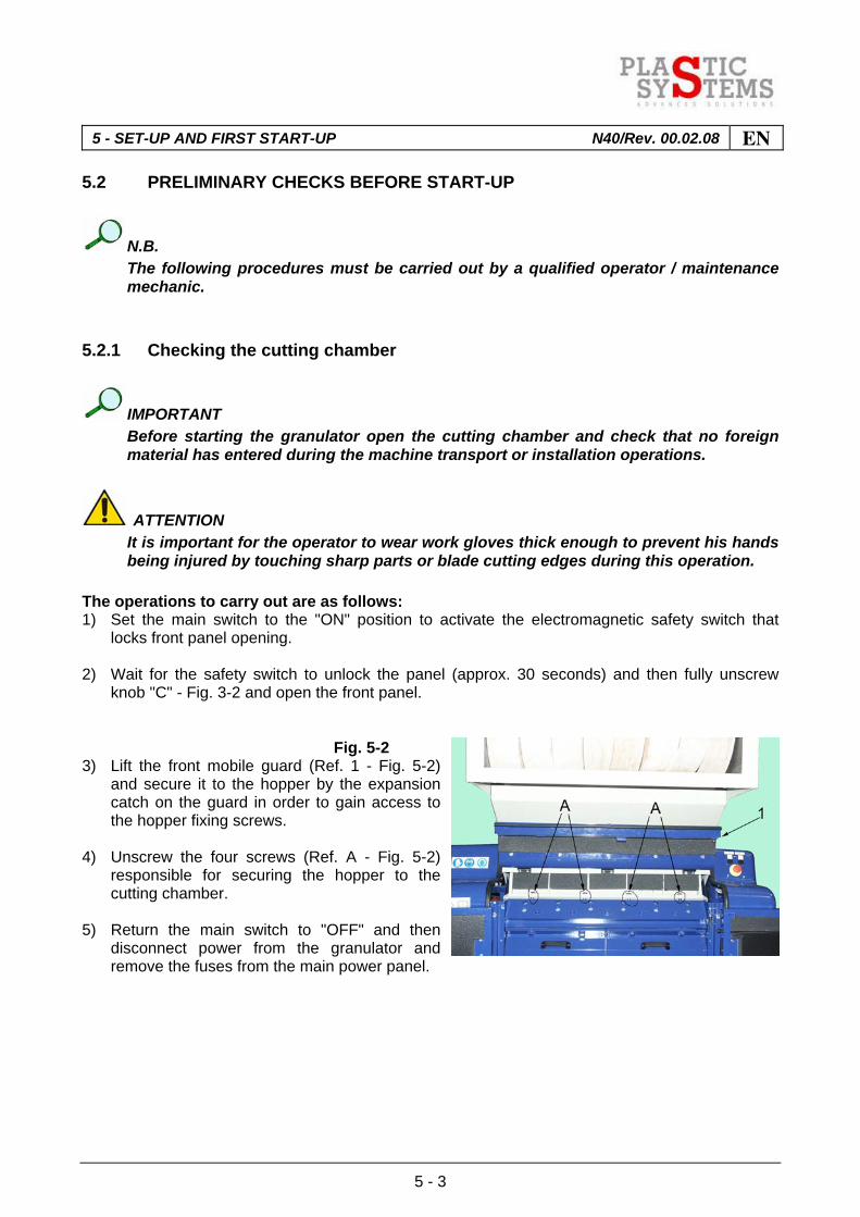
knob "C" - Fig. 3-2 and open the front panel. Fig. 5-2 3) Lift the front mobile guard (Ref. 1 - Fig. 5-2)
and secure it to the hopper by the expansion catch on the guard in order to gain access to the hopper fixing screws.
4) Unscrew the four screws (Ref. A - Fig. 5-2)
responsible for securing the hopper to the cutting chamber.
5) Return the main switch to "OFF" and then
disconnect power from the granulator and remove the fuses from the main power panel.

EN 5 - SET-UP AND FIRST START-UP N40/Rev. 00.02.08
5 - 4
Fig. 5-3 6) Tip the hopper fully back to achieve
unrestricted access to the cutting chamber and then check for the possible presence of foreign objects.
7) When the hopper is tipped backwards the
rear closing panel (Ref. B - Fig. 5-3) opens by sliding towards the rear.
Fig. 5-4
IMPORTANT If you wish to access the
motor/transmission compartment at this point, lift the rear panel and secure it to the rear wall of the hopper by means of the expansion catch on the panel (Ref. C - Fig. 5-4), then return the hopper to its starting position.
After performing the check, close the hopper (unless it is secured to the hopper also the rear panel will close automatically), then close the front mobile guard and finally, the front panel.
5 - SET-UP AND FIRST START-UP N40/Rev. 00.02.08 EN
5 - 5
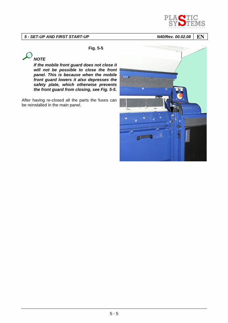
Fig. 5-5
NOTE If the mobile front guard does not close it
will not be possible to close the front panel. This is because when the mobile front guard lowers it also depresses the safety plate, which otherwise prevents the front guard from closing, see Fig. 5-5.
After having re-closed all the parts the fuses can be reinstalled in the main panel.
EN 5 - SET-UP AND FIRST START-UP N40/Rev. 00.02.08
5 - 6
5.2.2 Check of granulator rotation direction
Check correct direction of rotation ofimpeller as follows: - Turn master switch to position ‘ON’. - Press start button, holding it down for about one second, so that start clearances are checked
and granulator can start. - Check through the drive-guard spyhole that the rotor rotation direction is as stated on the plate
with a straight arrow attached above the protective guard. If direction of rotation is correct, granulator is ready for use.
ATTENTION If impeller is found rotating in the opposite direction to the straight arrow on plate, to
correct the direction of rotation, stop granulator by pressing EMERGENCY STOP; then cut off current by turning MASTER SWITCH to position ‘OFF’, disconnect fuses from line supply panel, then reverse one of the three electricity supply phase conductors inside the control panel.
After these operations, close control console door, refit fuses to power line supply panel, turn MASTER SWITCH to position ‘ON’ and reset EMERGENCY STOP button by pulling the red mushroom-head outwards. Press START button and hold down for about one second, then recheck that direction of rotation of rotor is correct. 5.2.3 Checking the direction of rotation of the suction fan (if installed)
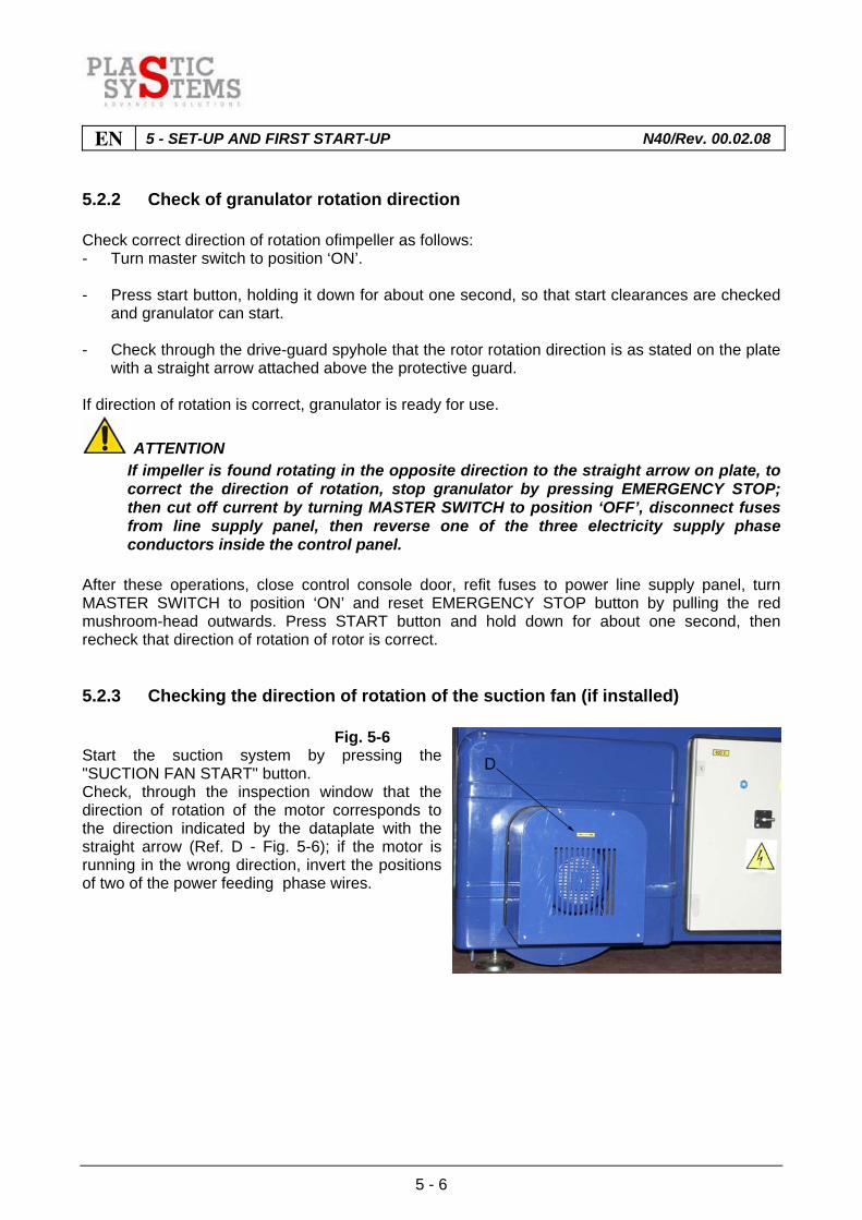
Fig. 5-6 Start the suction system by pressing the "SUCTION FAN START" button. Check, through the inspection window that the direction of rotation of the motor corresponds to the direction indicated by the dataplate with the straight arrow (Ref. D - Fig. 5-6); if the motor is running in the wrong direction, invert the positions of two of the power feeding phase wires.
5 - SET-UP AND FIRST START-UP N40/Rev. 00.02.08 EN
5 - 7
5.2.4 Checking position of fixed blades
ATTENTION It is necessary for this operation to be performed by a qualified ‘operator/mechanical
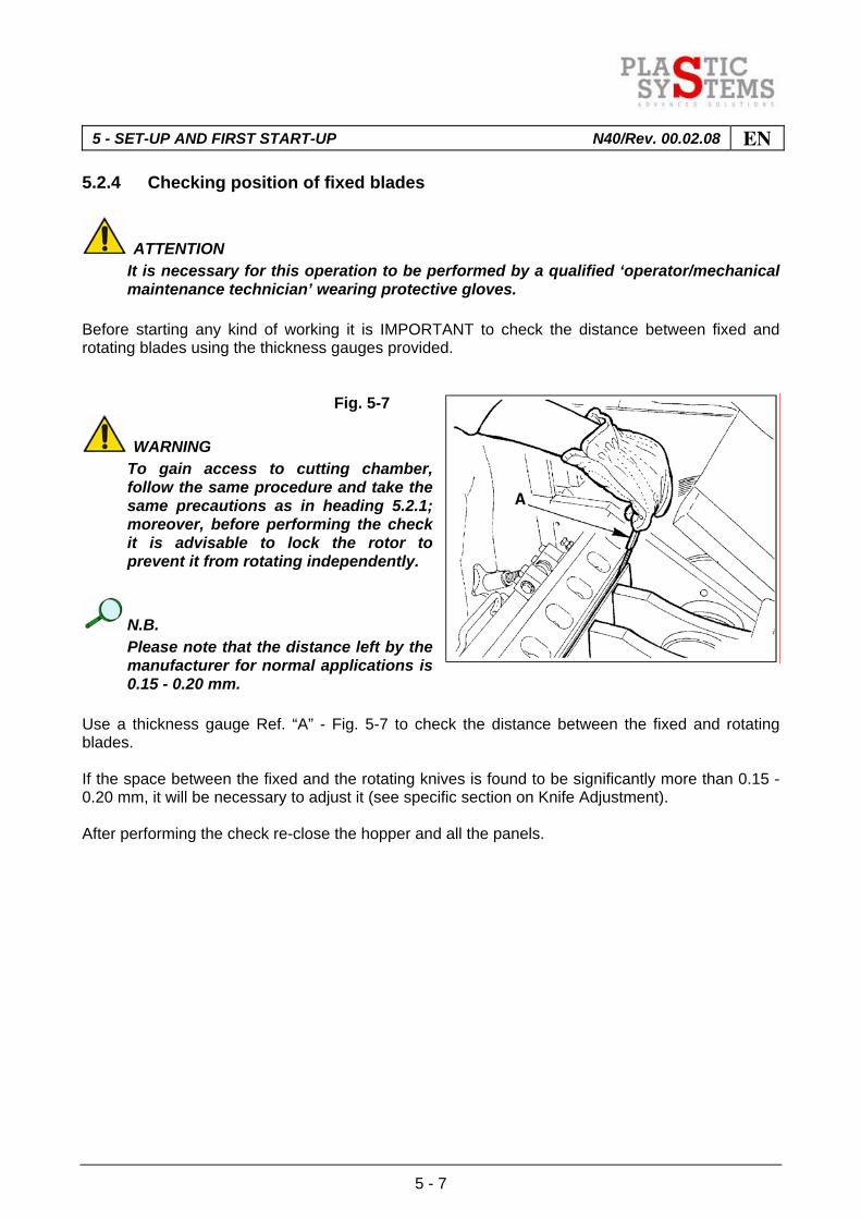
maintenance technician’ wearing protective gloves. Before starting any kind of working it is IMPORTANT to check the distance between fixed and rotating blades using the thickness gauges provided. Fig. 5-7
WARNING To gain access to cutting chamber,
follow the same procedure and take the same precautions as in heading 5.2.1; moreover, before performing the check it is advisable to lock the rotor to prevent it from rotating independently.
N.B. Please note that the distance left by the
manufacturer for normal applications is 0.15 - 0.20 mm.
Use a thickness gauge Ref. “A” - Fig. 5-7 to check the distance between the fixed and rotating blades. If the space between the fixed and the rotating knives is found to be significantly more than 0.15 - 0.20 mm, it will be necessary to adjust it (see specific section on Knife Adjustment). After performing the check re-close the hopper and all the panels.

EN 5 - SET-UP AND FIRST START-UP N40/Rev. 00.02.08
5 - 8
5.2.5 Checking position of rotating blades
Fig. 5-8
ATTENTION It is necessary for this operation to be
performed by a qualified “operator/mechanical maintenance technician” wearing protective gloves.
WARNING To gain access to the cutting
chamber, follow the same procedure and take the same precautions as indicated in heading 5.2.1; moreover, before performing the check it is advisable to lock the rotor to prevent it from rotating independently.
Using an 0.05 feeler gauge (Ref. "A" - Fig. 5-8) check correct positioning of rotating knife, Ref."B" - Fig. 5-8. If the knife is not correctly positioned loosen the fixing screws (Ref."C" - Fig. 5-9), reposition it and then lock it by means of a torque wrench. Fig. 5-9
NOTE Driving torque of rotating blade bolts:
20.2 Kgm. (202 Nm.).
IMPORTANT Smear a light coat of lube oil on all
screws to prevent seizure. After performing the check re-close the hopper and all the panels.

5 - SET-UP AND FIRST START-UP N40/Rev. 00.02.08 EN
5 - 9
5.3 OPERATING MODES
Granulator is designed to operate exclusively in automatic mode. After having enabled all the units required for the production cycle, the granulator requires exclusively the supply of material, which can be performed manually by the operator, or automatically by means of a feeding system.

EN 5 - SET-UP AND FIRST START-UP N40/Rev. 00.02.08
5 - 10
5.4 STOP AND EMERGENCY MODES
5.4.1 Stopping the work cycle
To stop the work cycle proceed as follows: - Ensure that the cutting chamber is empty;
ATTENTION Before pressing the "GRANULATOR STOP" pushbutton, ensure that the cutting
chamber is completely empty; to make this check it is sufficient to listen to the noise made by the granulator; when the granulator starts to run silently, you can assume that the cutting chamber is empty.
- Press the "GRANULATOR STOP" button; - Press the "SUCTION UNIT STOP" pushbutton, if the suction option is installed.
5.4.2 Emergency stop
The emergency stop, performed by pressing the mushroom head emergency pushbutton, causes the machine to stop immediately and disconnects the power supply. This type of stop must be carried out to stop the machine in case of hazard to persons and things, or in case of a long idle period of the machine and before performing maintenance work.
ATTENTION This type of stop shall only be used when emergency conditions really occur.
NOTE To reset the emergency pushbutton pull the mushroom head outwards. 5.4.3 Stop due to electrical power loss
In the event of an electrical power failure, the operating cycle will stop immediately; this situation could result in jamming of the rotor because of the material still present in the cutting chamber. To restore normal operating conditions following a power loss, perform all the checks already described in headings 5.2.1, 5.2.2, 5.2.3, 5.2.4 and 5.2.5 and, if necessary, perform the "ROTOR UNBLOCKING" procedure as described in heading 7.9. For any adjustments that may be required, refer to chapter 7 "MAINTENANCE".

6 - OPERATION N40/Rev. 00.02.08 EN
6 - 1
INDEX
6.1 OPERATIONS FOR START-UP AND PRODUCTION....................................................2
EN 6 - OPERATION N40/Rev. 00.02.08
6 - 2
6.1 OPERATIONS FOR START-UP AND PRODUCTION
ATTENTION Before starting the granulator, always check for and remove any equipment, tools or
other objects placed on the granulator. Turn MASTER SWITCH to position ‘ON’, then press START button and release only when motor has started. Fig. 6-1
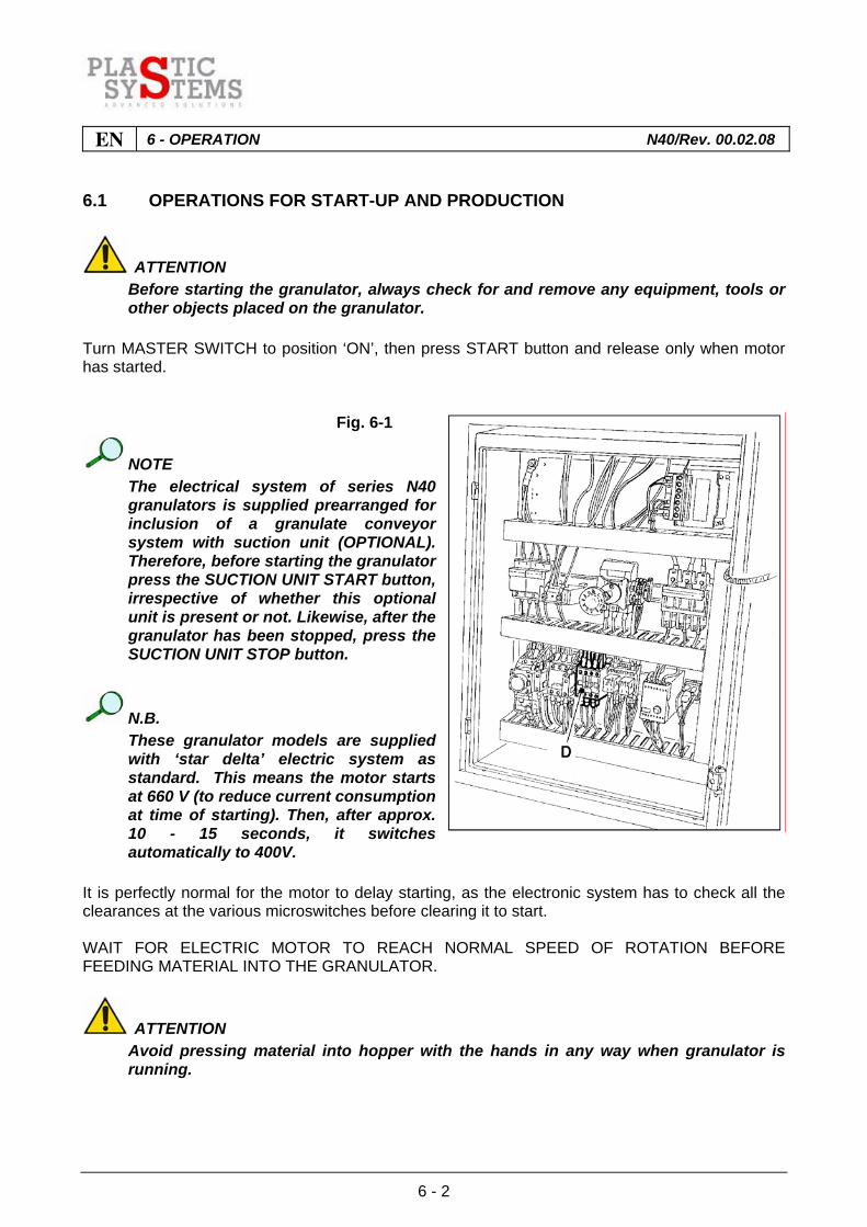
NOTE The electrical system of series N40
granulators is supplied prearranged for inclusion of a granulate conveyor system with suction unit (OPTIONAL). Therefore, before starting the granulator press the SUCTION UNIT START button, irrespective of whether this optional unit is present or not. Likewise, after the granulator has been stopped, press the SUCTION UNIT STOP button.
N.B. These granulator models are supplied
with ‘star delta’ electric system as standard. This means the motor starts at 660 V (to reduce current consumption at time of starting). Then, after approx. 10 - 15 seconds, it switches automatically to 400V.
It is perfectly normal for the motor to delay starting, as the electronic system has to check all the clearances at the various microswitches before clearing it to start. WAIT FOR ELECTRIC MOTOR TO REACH NORMAL SPEED OF ROTATION BEFORE FEEDING MATERIAL INTO THE GRANULATOR.
ATTENTION Avoid pressing material into hopper with the hands in any way when granulator is
running.

6 - OPERATION N40/Rev. 00.02.08 EN
6 - 3
If the hopper clogs, stop the granulator, turn off power supply and remove fuses.
IMPORTANT If the granulator stops repeatedly while working, it is necessary to check the setting
of the THERMOSWITCH ‘D’ - Fig. 6-1 (see figure shown on circuit diagram). Before stopping the granulator at the end of a shift or for other reasons, stop the supply of material for granulation and wait a few minutes to allow the cutting chamber to finish grinding the material inside it. Then press stop button.
ATTENTION Before pressing the stop button, make sure the cutting chamber is completely empty.
To check this just listen to the noise coming from the granulator. When it becomes silent, it means the cutting chamber is empty.
NOTE Should the granulator lock or stop with the cutting chamber full of material, proceed
emptying the room by removing the granules collection box and lowering the grid holder along with the grid.
NOTE It is good practice to clean the machine carefully after each work shift.
IMPORTANT When cleaning operations are concluded always check for possible residues of
granulate in the motor/transmission area and remove any residues fine by means of a vacuum cleaner.

EN 6 - OPERATION N40/Rev. 00.02.08
6 - 4

7 - MAINTENANCE N40/Rev. 00.02.08 EN
7 - 1
INDEX
7.1 GENERAL PRESCRIPTIONS .........................................................................................2
7.2 CHECKING THE SAFETY DEVICES..............................................................................3
7.2.1 Checking the emergency stop pushbuttons ....................................................................3
7.2.2 Checking the front panel opening safety electromagnetic switch....................................4
7.2.3 Checking the rear panel opening safety microswitch ......................................................4
7.3 MONTHLY MAINTENANCE OPERATIONS ...................................................................5
7.3.1 Drive belt tensioning........................................................................................................5
7.3.2 Drive belt checking and adjustment ................................................................................6
7.3.3 Belt replacement .............................................................................................................7
7.4 GRILLE REMOVAL AND REPLACEMENT.....................................................................8
7.5 CHECKING AND ADJUSTING THE FIXED BLADES...................................................10
7.5.1 Adjustment of front fixed blades ....................................................................................11
7.5.2 Rear fixed blade adjustment..........................................................................................13
7.6 REMOVAL AND REPLACEMENT OF FIXED BLADES................................................15
7.7 REMOVAL AND REPLACEMENT OF ROTATING BLADES........................................17
7.8 SPECIFICATIONS FOR SHARPENING FIXED BLADES.............................................19
7.9 ROTATING BLADE SHARPENING SPECIFICATIONS................................................20
7.10 ROTOR UNBLOCKING PROCEDURE.........................................................................21

EN 7 - MAINTENANCE N40/Rev. 00.02.08
7 - 2
7.1 GENERAL PRESCRIPTIONS
Before doing anything, read the instructions in this publication carefully.
ATTENTION Rely on specialised and skilled staff for these operations (see heading 0.4). - All maintenance operations shall be carried out with the granulator stationary and
disconnected from the electricity mains. - When the electric equipment is live, some parts of it may be dangerous. - Failure to follow the safety instructions when using such equipment may cause personal injury
or damage to objects. - Strictly follow the instructions in the paragraphs concerning each maintenance operation. Having carried out the maintenance work, before returning the granulator to service check that: 1 Any parts replaced and/or equipment used for the maintenance have been removed from the
granulator. 2 All safety devices are working.
IMPORTANT After the first week of production, check the tensioning of the drive belts. The correct
working tensioning level shall be the minimum required so that the belts do not slip. Check that the pulleys are properly aligned one with the other, as well.
IMPORTANT If it becomes necessary to wash the granulator never use pressurised water jets.

7 - MAINTENANCE N40/Rev. 00.02.08 EN
7 - 3
7.2 CHECKING THE SAFETY DEVICES
IMPORTANT At the start of each working shift, perform the checks listed below.
IMPORTANT If safety devices must be repaired or replaced, rely on skilled and competent
personnel (see heading 0.4), or on CMG technical service department. 7.2.1 Checking the emergency stop pushbuttons
With the machine empty and set up for operation, perform the following operations: 1) press the "SUCTION UNIT START" pushbutton, and hold it down for about one second to
allow the transmission of all the relative enable signals so that the suction unit (if present) can start;
2) press the "GRANULATOR START" pushbutton, and hold it down for about one second to allow the transmission of all the relative enable signals so that the granulator can start;
3) now press one of the emergency stop pushbuttons, and check that both the granulator and the suction system (if present) are stopped;
4) when you have finished performing the check reset the emergency pushbutton that was pressed by pulling the mushroom head outwards.
IMPORTANT Peform the foregoing check for each of the emergency pushbuttons.

EN 7 - MAINTENANCE N40/Rev. 00.02.08
7 - 4
7.2.2 Checking the front panel opening safety electromagnetic switch
With the machine empty and set up for operation, perform the following operations: 1) press the "SUCTION UNIT START" pushbutton, and hold it down for about one second to
allow the transmission of all the relative enable signals so that the suction unit (if present) can start;
2) press the "GRANULATOR START" pushbutton, and hold it down for about one second to allow the transmission of all the relative enable signals so that the granulator can start;
3) allow the machine to run for a few seconds and then press the following pushbuttons in
sequence: - "GRANULATOR STOP"; - "SUCTION UNIT STOP"; 4) if the sensor is working correctly, it doesn't allow opening the front door immediately. This is
because the microswitch connected to sensor allows opening the front door only when the sensor detects no rotor movement (30 sec. about).
7.2.3 Checking the rear panel opening safety microswitch
With the machine empty and set up for operation, perform the following operations: 1) execute all the operations described in heading 5.2.1 up to point 7; 2) raise the rear panel and secure it to the hopper by means of the expansion catch, see Fig. 5-4; 3) close the hopper, the front guard, and finally close the front panel, screwing down the knob
completely (Ref. C - Fig. 3-2); 4) Press the "SUCTION UNIT START" pushbutton and hold it down for approximately 1 second
and then press the "GRANULATOR START" pushbutton and check that the suction unit (if present) and the granulator do not start.
7 - MAINTENANCE N40/Rev. 00.02.08 EN
7 - 5
7.3 MONTHLY MAINTENANCE OPERATIONS
NOTE Have these operations carried out by an 'operator/mechanical maintenance
technician'. 7.3.1 Drive belt tensioning
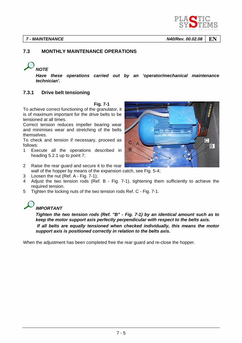
Fig. 7-1 To achieve correct functioning of the granulator, it is of maximum important for the drive belts to be tensioned at all times. Correct tension reduces impeller bearing wear and minimises wear and stretching of the belts themselves. To check and tension if necessary, proceed as follows: 1 Execute all the operations described in
heading 5.2.1 up to point 7; 2 Raise the rear guard and secure it to the rear
wall of the hopper by means of the expansion catch, see Fig. 5-4; 3 Loosen the nut (Ref. A - Fig. 7-1); 4 Adjust the two tension rods (Ref. B - Fig. 7-1), tightening them sufficiently to achieve the
required tension. 5 Tighten the locking nuts of the two tension rods Ref. C - Fig. 7-1.
IMPORTANT Tighten the two tension rods (Ref. "B" - Fig. 7-1) by an identical amount such as to
keep the motor support axis perfectly perpendicular with respect to the belts axis. If all belts are equally tensioned when checked individually, this means the motor
support axis is positioned correctly in relation to the belts axis. When the adjustment has been completed free the rear guard and re-close the hopper.
EN 7 - MAINTENANCE N40/Rev. 00.02.08
7 - 6
7.3.2 Drive belt checking and adjustment
Check the tension of the drive belts initially after 8 or 10 hours of duty and, if necessary, adjust in accordance with the tabulated values. Check the tension and condition of the belts once a month thereafter. Whenever you adjust belt tension, recheck the situation after 20 or 30 duty hours at full load.
NOTE After tensioning the belts always check that the pulleys are correctly aligned.
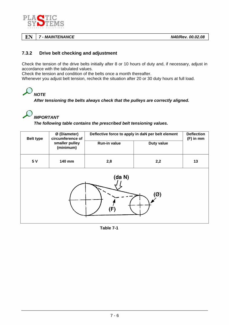
IMPORTANT The following table contains the prescribed belt tensioning values.
Deflective force to apply in daN per belt element
Belt type
Ø (Diameter) circumference of
smaller pulley (minimum)
Run-in value Duty value
Deflection (F) in mm
5 V
140 mm
2,8
2,2
13
Table 7-1

7 - MAINTENANCE N40/Rev. 00.02.08 EN
7 - 7
7.3.3 Belt replacement
ATTENTION It is very important to replace all belts at the same time. If it becomes necessary to renew the drive belts, observe the procedure adopted up to point 3 in heading 7.2.1 and then de-tension the belts by unscrewing the two tension rods (Ref. B - Fig. 7-1) Now tighten the nut (Ref. A - Fig. 7-1) until the belts have been loosened completely. Now simply withdraw the belts and fit new ones, repeating the steps described from point 3 of heading 7.2.1 referred to belt tensioning.
EN 7 - MAINTENANCE N40/Rev. 00.02.08
7 - 8
7.4 GRILLE REMOVAL AND REPLACEMENT
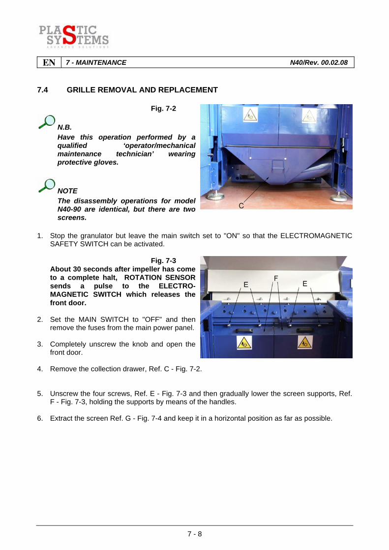
Fig. 7-2
N.B. Have this operation performed by a
qualified ‘operator/mechanical maintenance technician’ wearing protective gloves.
NOTE The disassembly operations for model
N40-90 are identical, but there are two screens.
1. Stop the granulator but leave the main switch set to "ON" so that the ELECTROMAGNETIC
SAFETY SWITCH can be activated. Fig. 7-3 About 30 seconds after impeller has come
to a complete halt, ROTATION SENSOR sends a pulse to the ELECTRO-MAGNETIC SWITCH which releases the front door.
2. Set the MAIN SWITCH to "OFF" and then
remove the fuses from the main power panel. 3. Completely unscrew the knob and open the
front door. 4. Remove the collection drawer, Ref. C - Fig. 7-2. 5. Unscrew the four screws, Ref. E - Fig. 7-3 and then gradually lower the screen supports, Ref.
F - Fig. 7-3, holding the supports by means of the handles. 6. Extract the screen Ref. G - Fig. 7-4 and keep it in a horizontal position as far as possible.
7 - MAINTENANCE N40/Rev. 00.02.08 EN
7 - 9
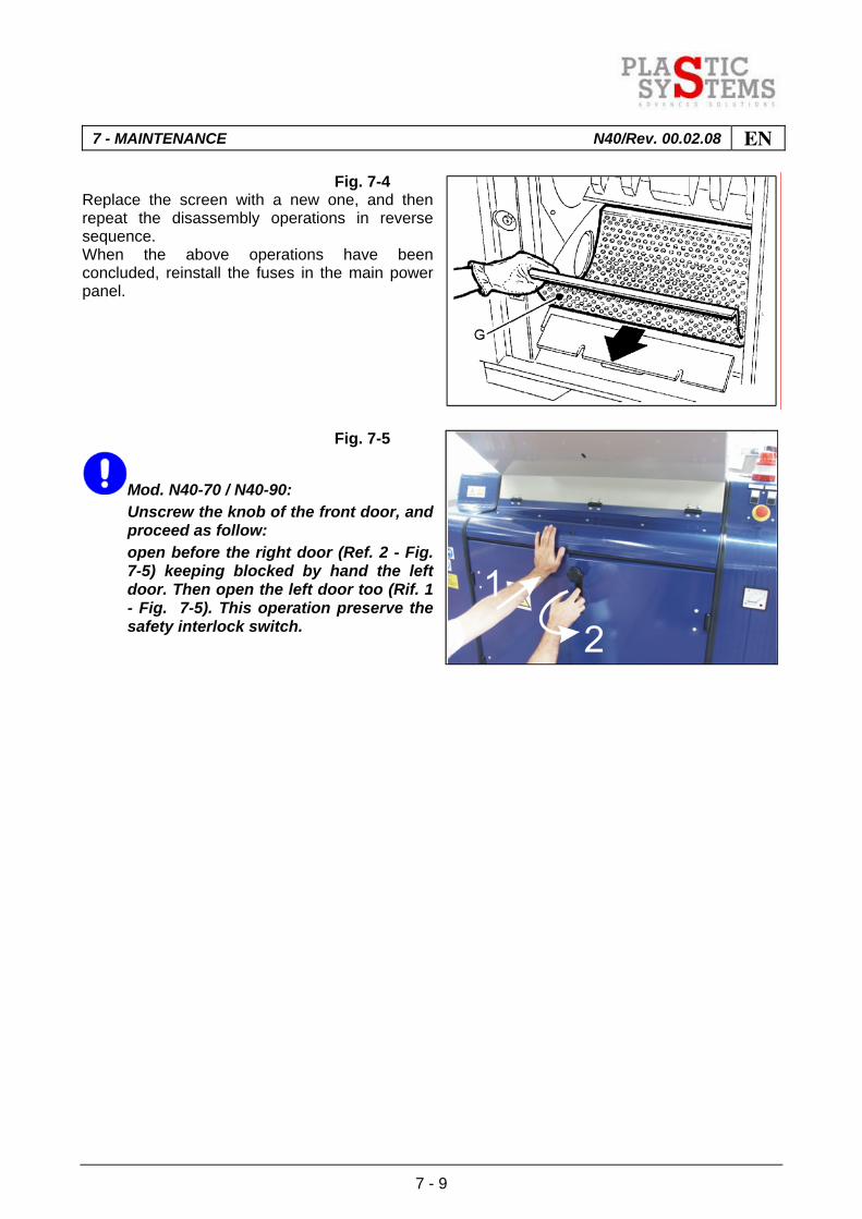
Fig. 7-4 Replace the screen with a new one, and then repeat the disassembly operations in reverse sequence. When the above operations have been concluded, reinstall the fuses in the main power panel.
Fig. 7-5
Mod. N40-70 / N40-90: Unscrew the knob of the front door, and
proceed as follow: open before the right door (Ref. 2 - Fig.
7-5) keeping blocked by hand the left door. Then open the left door too (Rif. 1 - Fig. 7-5). This operation preserve the safety interlock switch.
EN 7 - MAINTENANCE N40/Rev. 00.02.08
7 - 10
7.5 CHECKING AND ADJUSTING THE FIXED BLADES
N.B. Have this operation done by a qualified ‘operator/mechanical maintenance
technician’.
ATTENTION Before carrying out any maintenance on the cutting chamber, the operator must use
suitable personal protection devices, namely work gloves having the characteristics specified by standard EN 388, to prevent the risk of injury to the hands caused by contact with pointed or sharp edges of the blades.
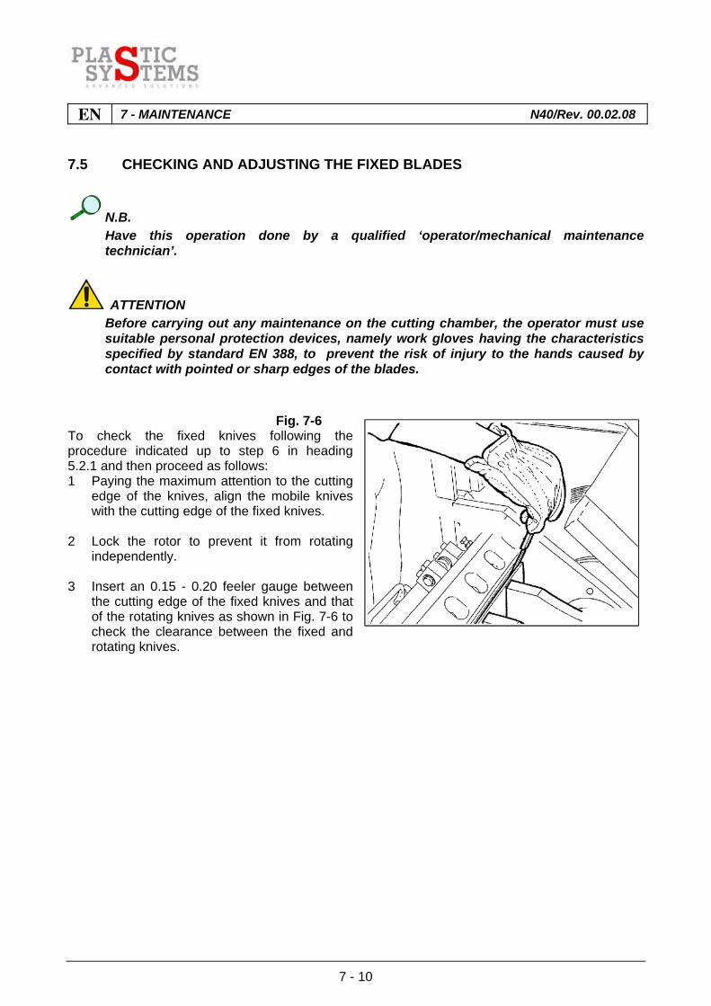
Fig. 7-6 To check the fixed knives following the procedure indicated up to step 6 in heading 5.2.1 and then proceed as follows: 1 Paying the maximum attention to the cutting
edge of the knives, align the mobile knives with the cutting edge of the fixed knives.
2 Lock the rotor to prevent it from rotating
independently. 3 Insert an 0.15 - 0.20 feeler gauge between
the cutting edge of the fixed knives and that of the rotating knives as shown in Fig. 7-6 to check the clearance between the fixed and rotating knives.

7 - MAINTENANCE N40/Rev. 00.02.08 EN
7 - 11
7.5.1 Adjustment of front fixed blades
Fig. 7-7 If necessary, adjust as follows: 1 Loosen the screws Ref. "B"- Fig. 7-7
securing the fixed knives. 2 Tighten the two outermost screws
moderately Ref. "C"- Fig. 7-7.
Fig. 7-8 3 Use a hex wrench to tighten the specific
adjustment screws and nuts Ref. "D"- Fig. 7-7.
4 Insert an 0.15-0.20 mm feeler gauge
between the cutting edge of the fixed knife and that of the rotating knife as shown in the diagram in Fig. 7-8;
A - Feeler gauge B - Rotating knife C - Fixed knife (counter-blade) 5 Reposition by acting on the adjustment screws in such a way as to create the necessary
clearance to allow the feeler gauge to be moved to and fro.

EN 7 - MAINTENANCE N40/Rev. 00.02.08
7 - 12
Fig. 7-9
ATTENTION Check that distance between fixed and
rotating blades is the same at each end of each blade. Shift fixed blades a little at a time, but on both sides, using the grub screws to adjust.
On completion of the adjustment, lock retaining nuts making sure that the edge of the guard (Ref. "P" - Fig. 7-9) is perfectly level with the blade profile (Ref. "L" - Fig. 7-9), then, using a torque wrench, tighten the lock bolts as shown in Fig. 7-10. Fig. 7-10
NOTE Fixed knife screws tightening torque: Model N40-50 = 20.2 kgm (202 Nm). Model N40-70/N40-90 = 30.2 kgm (302 Nm).
IMPORTANT Smear a light coat of lube oil on all screws
to prevent seizure.

7 - MAINTENANCE N40/Rev. 00.02.08 EN
7 - 13
7.5.2 Rear fixed blade adjustment
Fig. 7-11 To adjust the rear fixed blades, proceed as follows: 1 Rotate the rotor in such a way as to bring
the rotating knives into position.
ATTENTION Cover the cutting edges of the
rotating blades at the top ‘A’ - Fig. 7-11 with suitable protection, because they could pose a hazard to the operator who could be injured through having to work over them.
Fig. 7-12 2 Loosen the screws Ref. "B" - Fig. 7-11
securing the fixed knives; 3 Tighten the two outermost screws moderately
Ref. "C" - Fig. 7-11; 4 use a hex wrench to loosen the locking nuts
and relative adjustment screws Ref. "D" - Fig. 7-11;
5 use an 0.15-0.20 mm feeler gauge to check
the distance between the fixed knife and rotating knife as shown in Fig. 7-12.
6 use a hex wrench to adjust the knives by acting on the relative screws and then lock them by
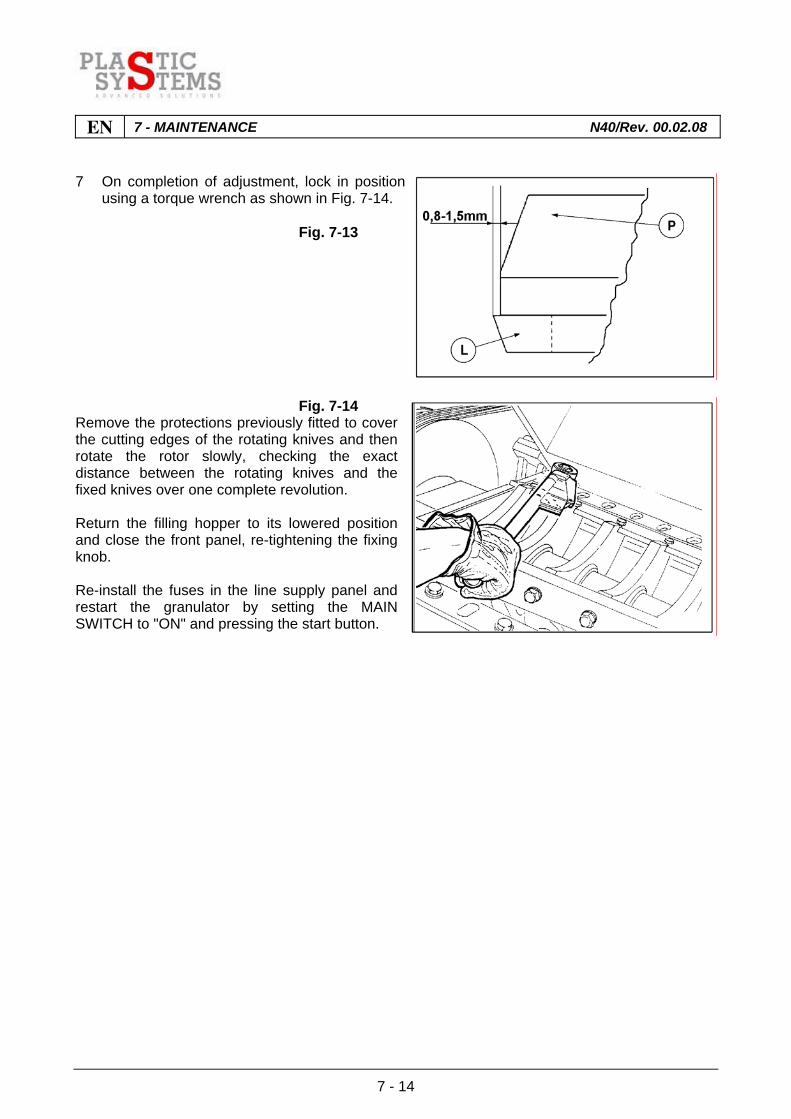
means of the relative locking nuts, in such a way that clearance of approximately 0.8 - 1.5 mm is created between the knife, Ref. L - Fig. 7-13, and the corresponding guard, Ref. P - Fig. 7-13;
EN 7 - MAINTENANCE N40/Rev. 00.02.08
7 - 14
7 On completion of adjustment, lock in position using a torque wrench as shown in Fig. 7-14.
Fig. 7-13
Fig. 7-14 Remove the protections previously fitted to cover the cutting edges of the rotating knives and then rotate the rotor slowly, checking the exact distance between the rotating knives and the fixed knives over one complete revolution. Return the filling hopper to its lowered position and close the front panel, re-tightening the fixing knob. Re-install the fuses in the line supply panel and restart the granulator by setting the MAIN SWITCH to "ON" and pressing the start button.
7 - MAINTENANCE N40/Rev. 00.02.08 EN
7 - 15
7.6 REMOVAL AND REPLACEMENT OF FIXED BLADES
N.B. Have the operation carried out by a qualified ‘operator/mechanical maintenance
technician’.
ATTENTION Before carrying out any maintenance on the cutting chamber, it is compulsory for the
operator to wear work gloves thick enough to avoid injury to the hands through touching sharp parts or the cutting edges of the blades.
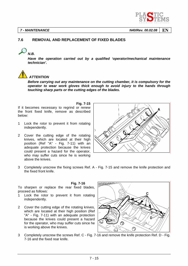
Fig. 7-15 If it becomes necessary to regrind or renew the front fixed knife, remove as described below: 1 Lock the rotor to prevent it from rotating
independently. 2 Cover the cutting edge of the rotating
knives, which are located at their high position (Ref "A" - Fig. 7-11) with an adequate protection because the knives could present a hazard for the operator, who may suffer cuts since he is working above the knives.
3 Completely unscrew the fixing screws Ref. A - Fig. 7-15 and remove the knife protection and
the fixed front knife. Fig. 7-16 To sharpen or replace the rear fixed blades, proceed as follows: 1 Lock the rotor to prevent it from rotating
independently. 2 Cover the cutting edge of the rotating knives,
which are located at their high position (Ref "A" - Fig. 7-11) with an adequate protection because the knives could present a hazard for the operator, who may suffer cuts since he is working above the knives.
3 Completely unscrew the screws Ref. C - Fig. 7-16 and remove the knife protection Ref. D - Fig.
7-16 and the fixed rear knife.

EN 7 - MAINTENANCE N40/Rev. 00.02.08
7 - 16
ATTENTION Before refitting blades, clean holder carefully with a rag.
N.B. To refit sharpened fixed blades, the same screws and washers that were holding it on
can be used. When new fixed blades are being fitted, however, it is necessary to replace the screws
and washers with new ones of the same strength.
NOTE Tightening torque for fixed blade bolts: Mod. N40-50 = 20,2 kgm (202 Nm). Mod. N40-70/N40-90 = 30,2 kgm (302 Nm).
IMPORTANT All screws must be moistened with a film of lubricating oil to prevent jamming.
Carefully clean holder of fixed blades before refitting them. Restore the correct distance with the rotating knives as already described in paragraph 7.4, then lock the screws with a torque wrench. Remove the protections previously fitted to cover the cutting edges of the rotating knives and then rotate the rotor slightly, checking through one complete revolution, the exact distance between the rotating knives and the fixed knives. Return the filling hopper to its lowered position and close the front panel, re-tightening the fixing knob. Re-install the fuses in the line supply panel and restart the granulator by setting the MAIN SWITCH to "ON" and pressing the start button.

7 - MAINTENANCE N40/Rev. 00.02.08 EN
7 - 17
7.7 REMOVAL AND REPLACEMENT OF ROTATING BLADES
N.B. Have the operation carried out by a qualified ‘operator/mechanical maintenance
technician’.
ATTENTION Before carrying out any maintenance on the cutting chamber, it is compulsory for the
operator to wear work gloves thick enough to avoid injury to the hands through touching sharp parts or the cutting edges of the blades.
Fig. 7-17 If it proves necessary to sharpen or replace the rotating blades, it will be necessary to dismantle them, proceeding as described up to paragraph 7.3 point 4, then completely unscrew fastening bolts Ref. ‘1’ - Fig. 7-17 and remove blades.
IMPORTANT When rotating blades are removed for
sharpening, it is necessary to sharpen the complete set of blades.
ATTENTION Before refitting blades, clean holders carefully with a rag.
N.B. To refit rotating blades which have been sharpened only, the same screws and
washers that were holding them on can be used. When new rotating blades blades are being fitted, however, it is necessary to replace
the screws and washers with new ones of the same strength. Using an 0.05 feeler gauge (Ref. "A" - Fig. 5-8) check correct positioning of rotating knife "B" - Fig. 5-8. If the knife is not correctly positioned, loosen the fixing screws ("1" - Fig. 7-17), reposition it and then lock it using a torque wrench.
NOTE Tightening torque of rotating blade bolts: 20,2 kgm (202 Nm)

EN 7 - MAINTENANCE N40/Rev. 00.02.08
7 - 18
Restore the correct distance between the fixed knives and the rotating knives as already described in paragraph 7.4, then lock the screws with a torque wrench. Rotate the rotor slowly, checking the exact distance between the rotating knives and the fixed knives over one complete revolution. Return the loading hopper to its lowered position and close the front panel, re-tightening the fixing knob. Re-install the fuses in the line supply panel and restart the granulator by setting the MAIN SWITCH to "ON" and pressing the start button.

7 - MAINTENANCE N40/Rev. 00.02.08 EN
7 - 19
7.8 SPECIFICATIONS FOR SHARPENING FIXED BLADES
Each fixed blade has two cutting edges, one each side. When a cutting edge is worn, the blades can be turned. To sharpen these blades, refer to the data in (Fig. 7-18). Replacement of these blades becomes necessary when their length falls below the set tolerances.
Fig. 7-18
Min. length “B” (mm) New blade “C” (mm) α Series ‘N40’ GRANULATORS
60
68
20°
Table 7-2
EN 7 - MAINTENANCE N40/Rev. 00.02.08
7 - 20
7.9 ROTATING BLADE SHARPENING SPECIFICATIONS
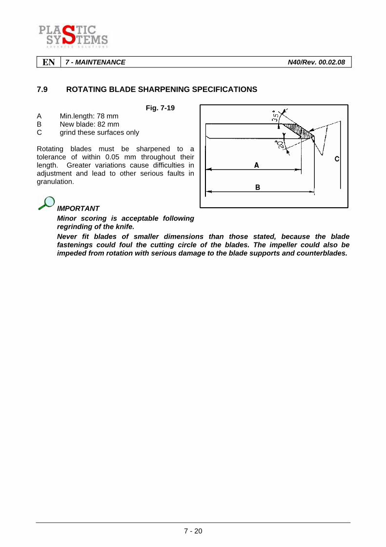
Fig. 7-19 A Min.length: 78 mm B New blade: 82 mm C grind these surfaces only Rotating blades must be sharpened to a tolerance of within 0.05 mm throughout their length. Greater variations cause difficulties in adjustment and lead to other serious faults in granulation.
IMPORTANT Minor scoring is acceptable following
regrinding of the knife. Never fit blades of smaller dimensions than those stated, because the blade
fastenings could foul the cutting circle of the blades. The impeller could also be impeded from rotation with serious damage to the blade supports and counterblades.
7 - MAINTENANCE N40/Rev. 00.02.08 EN
7 - 21
7.10 ROTOR UNBLOCKING PROCEDURE
NOTE Before performing any type of maintenance of the cutting chamber it is compulsory
for the operator to use suitable personal protection devices, i.e. work gloves having the characteristics specified by standard EN 388; also, the blades must be protected by fitting rubber guards to avoid injury to the hands through touching sharp parts or the cutting edges.
If the rotor becomes jammed because of a build-up of material in the cutting chamber, indicated also anomalous granulator running noise, proceed as follows: - press one of the emergency stop pushbuttons; - reset the emergency stop pushbutton; - leave the main switch set to "ON" so that the ELECTROMAGNETIC SAFETY SWITCH can be
activated and the front door is unlocked; - open the granulator; - padlock the main power switch. - empty the cutting chamber of all feedstock.
ATTENTION When the rotor is jammed, never try to free it with your hands: this operation is
extremely dangerous. Do not try to unblock the machine by placing your hands on the rotor, on the blades, or inside the cutting chamber. Keep hands well clear off the rotary trajectory of the rotor.
ATTENTION Before performing the following operations ensure that your feet are firmly planted on
the floor, that the floor is clean and unobstructed, and that your body is well balanced.
Beware of the possibility of losing your balance if the rotor should suddenly become unjammed.
To free the rotor when jammed by accumulated material, use a sturdy wooden lever of sufficient length to keep the hands well clear of the trajectory of the blades, and then lever the rotor in the direction opposite to the direction of rotation of the granulator. Use suitably long tongs to remove the material that caused the rotor to jam in the first place.
ATTENTION Be aware that the rotor may start to spin dangerously as soon as the obstructing
material is removed. After unblocking the machine, to restore normal operating conditions perform all the checks already described in headings 5.2.1, 5.2.2, 5.2.3, 5.2.4 and 5.2.5. For repair work (if necessary) refer to the procedures described in this section of the manual.

EN 7 - MAINTENANCE N40/Rev. 00.02.08
7 - 22

8 - TROUBLESHOOTING N40/Rev. 00.02.08 EN
8 - 1
INDEX
8.1 FAULTS, CAUSES AND REMEDIES..............................................................................2
8.2 ELECTRIC FAULTS........................................................................................................4

EN 8 - TROUBLESHOOTING N40/Rev. 00.02.08
8 - 2
8.1 FAULTS, CAUSES AND REMEDIES
The following pages list certain faults which may occur with the granulator. These general indications allow any fault to be located and a quick repair to be made. In any case, when looking for causes of faults, it is sound practice to start with simpler checks before carrying out complicated dismantling and useless solutions.
Fault Possible Cause Possible Remedy Bearings overheating Blades moving in holders
Excessive belt tension There may be foreign material under the blade. Loose blade screws Weakened blade screws
Adjust belt tensioning Clean holder carefully. Tighten screws with a torque wrench. Screws must not be used more than six times.
Blades broken Not sharpened correctly Extremely hard material Incorrect direction of rotation of impeller Foreign bodies in cutting chamber Grilles fitted wrongly
Check method of sharpening blades Contact supplier Check direction of rotation of impeller Look for cause with operator Check fitting procedure
Excessive blade wear Incorrect position of blades Abrasive material
Reset tolerance on distance bet-ween blade and counterblade Contact supplier to obtain special blades
Abnormal wear of grille Grille incorrecttly fitten Abrasive material
Check that grille is properly positioned on its rear holder and slots into front perfectly Contact supplier to obtain special grilles
Table 8-1A

8 - TROUBLESHOOTING N40/Rev. 00.02.08 EN
8 - 3
Fault Possible Cause Possible Remedy Impeller blocked Excessive feed
Total or partial clogging of grille holes Insufficient drive belt tension Blades worn or burnt Distance between blades too narrow Grille holes too small Ventilation system blocked
Reduce feed of material for granulation Remove grille and clean holes Check and/or adjust tension of drive belts Replace with new blades Check distance between blades Increase grille hole diameter Check direction of rotation of fan and that pipes are not blocked
Table 8-1B
EN 8 - TROUBLESHOOTING N40/Rev. 00.02.08
8 - 4
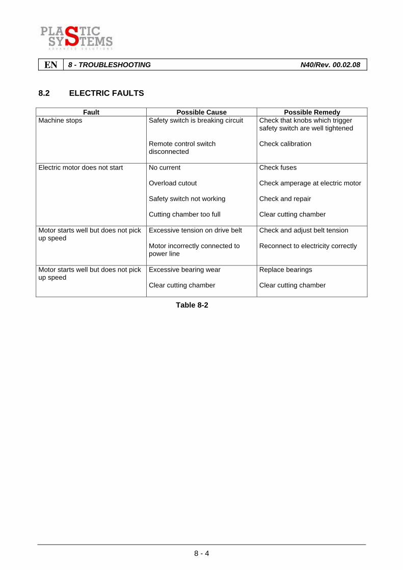
8.2 ELECTRIC FAULTS
Fault Possible Cause Possible Remedy Machine stops Safety switch is breaking circuit
Remote control switch disconnected
Check that knobs which trigger safety switch are well tightened Check calibration
Electric motor does not start No current Overload cutout Safety switch not working Cutting chamber too full
Check fuses Check amperage at electric motor Check and repair Clear cutting chamber
Motor starts well but does not pick up speed
Excessive tension on drive belt Motor incorrectly connected to power line
Check and adjust belt tension Reconnect to electricity correctly
Motor starts well but does not pick up speed
Excessive bearing wear Clear cutting chamber
Replace bearings Clear cutting chamber
Table 8-2

9 - DISPOSAL OF WASTE MATERIALS / SCRAPPING N40/Rev. 00.02.08 EN
9 - 1
INDEX
9.1 DECOMISSIONING.........................................................................................................2
9.1.1 Scrapping the granulator .................................................................................................2
EN 9 - DISPOSAL OF WASTE MATERIALS / SCRAPPING N40/Rev. 00.02.08
9 - 2
9.1 DECOMISSIONING
When it has been decided no longer to use the granulator, it is recommended to disable it by disconnecting the supply cable from the mains and inserting any safety devices. 9.1.1 Scrapping the granulator
ATTENTION The granulator shall be scrapped by skilled personnel: both electricians and
mechanics. Before dismantling the machine, prepare an wide and orderly space all around it in
such a way as to allow personnel to move without obstructions, i.e. without creating risks for operators and exposed persons.
Proceed as follows: - Disconnect the machine from the electrical mains and the water supply (if present); - Detach all the wires at the output of the line disconnect switch; - Detach the electrical cabinet power feeding wires; - Close the cock controlling the water supply to the cooling circuit (if present), and detach the
water inlet and outlet unions from the machine;
ATTENTION If the above procedures result in the formation of a wet area around the machine, it
should be thoroughly dried before proceeding. - Remove the fixed and rotary blades; - Disassemble the machine into its main sections; - Separate machine components on the basis of their type (e.g. plastic, metal, etc.)and dispose
of them at a sorted waste collection plant in your area.
IMPORTANT Observe all the regulations in force in the country of installation of the machine with
regard to the disposal of used machinery.

10 - OPTIONALS N40/Rev. 00.02.08 EN
10 - 1
INDEX
10.1 GRANULE TRANSPORTATION INSTALLATION WITH SUCTION SYSTEM..........................................................................................................................2
10.2 REMOVAL AND REPLACEMENT OF FIXED BLADES (TWIN SHEAR VERSION) .......................................................................................................................3
EN 10 - OPTIONALS N40/Rev. 00.02.08
10 - 2
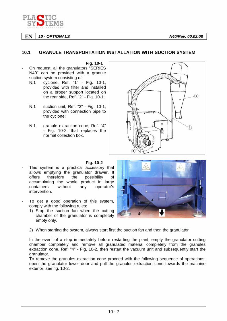
10.1 GRANULE TRANSPORTATION INSTALLATION WITH SUCTION SYSTEM
Fig. 10-1 - On request, all the granulators "SERIES
N40" can be provided with a granule suction system consisting of:
N.1 cyclone, Ref. "1" - Fig. 10-1, provided with filter and installed on a proper support located on the rear side, Ref. "2" - Fig. 10-1;
N.1 suction unit, Ref. "3" - Fig. 10-1,
provided with connection pipe to the cyclone;
N.1 granule extraction cone, Ref. "4"
- Fig. 10-2, that replaces the normal collection box.
Fig. 10-2 - This system is a practical accessory that
allows emptying the granulator drawer. It offers therefore the possibility of accumulating the whole product in large containers without any operator’s intervention.
- To get a good operation of this system,
comply with the following rules: 1) Stop the suction fan when the cutting
chamber of the granulator is completely empty only.
2) When starting the system, always start first the suction fan and then the granulator In the event of a stop immediately before restarting the plant, empty the granulator cutting
chamber completely and remove all granulated material completely from the granules extraction cone, Ref. "4" - Fig. 10-2, then restart the vacuum unit and subsequently start the granulator.
To remove the granules extraction cone proceed with the following sequence of operations: open the granulator lower door and pull the granules extraction cone towards the machine exterior, see fig. 10-2.
10 - OPTIONALS N40/Rev. 00.02.08 EN
10 - 3
10.2 REMOVAL AND REPLACEMENT OF FIXED BLADES (TWIN SHEAR VERSION)
N.B. Have the operation carried out by a qualified ‘operator / mechanical maintenance
technician’.
ATTENTION Before carrying out any maintenance on the cutting chamber, it is compulsory for the
operator to wear work gloves thick enough to avoid injury to the hands through touching sharp parts or the cutting edges of the blades.
Fig. 10-3 If it proves necessary to sharpen or replace the front fixed blades, it will be necessary to dismantle them, proceeding as described up to paragraph 7.4 point 2, then proceed as follows: 1 Lock the rotor to prevent it from rotating
independently. 2 Cover the cutting edge of the rotating knives,
which are located at their high position (Ref "A" - Fig. 7-11) with an adequate protection because the knives could present a hazard for the operator, who may suffer cuts since he is working above the knives.
3 Completely unscrew the fixing screws Ref. "A" - Fig. 10-3, remove the knife protections and
remove the front fixed knives; Fig. 10-4 To sharpen or replace the rear fixed blades, proceed as follows: 1 Lock the rotor to prevent it from rotating
independently. 2 Cover the cutting edge of the rotating knives,
which are located at their high position (Ref "A" - Fig. 7-11) with an adequate protection because the knives could present a hazard for the operator, who may suffer cuts since he is working above the knives.
3 Completely unscrew the screws Ref. "B" - Fig. 10-4, remove the fixed knife protections Ref. "C"
- Fig. 10-4 and the fixed rear knives.

EN 10 - OPTIONALS N40/Rev. 00.02.08
10 - 4
ATTENTION Before refitting both the front and rear fixed blades, clean holder carefully with a rag.
N.B. To refit sharpened fixed blades, the same screws and washers that were holding it on
can be used. When new fixed blades are being fitted, however, it is necessary to replace the screws
and washers with new ones of the same strength.
NOTE Tightening torque for fixed blade bolts: Mod. G40-50 = 20,2 kgm (202 Nm) Mod. G40-70/G40-90 = 30,2 kgm (302 Nm)
IMPORTANT All screws must be moistened with a film of lubricating oil to prevent jamming.
Carefully clean holder of fixed blades before refitting them. Restore the correct distance with the rotating knives as already described in paragraph 7.4, then lock the screws with a torque wrench. Remove the protections previously fitted to cover the cutting edges of the rotating knives and then rotate the rotor slightly, checking through one complete revolution, the exact distance between the rotating knives and the fixed knives. Return the filling hopper to its lowered position and close the front panel, re-tightening the fixing knob. Re-install the fuses in the line supply panel and restart the granulator by setting the MAIN SWITCH to "ON" and pressing the start button.

11 - SPARE PARTS LIST N40/Rev. 00.02.08 EN
11 - 1
INDEX
11.1 HOW TO ORDER SPARE PARTS..................................................................................2

EN 11 - SPARE PARTS LIST N40/Rev. 00.02.08
11 - 2
11.1 HOW TO ORDER SPARE PARTS
To request spare parts please apply to: PLASTIC SYSTEMS S.p.A. - Via G. Marconi, 6 – 35010 Borgoricco (PD) - Italy Tel. 0039-049-9335901 Fax 0039-049-9335905 always quoting: from the granulator dataplate: 1. Granulator model 2. Serial number from parts drawing: 1. Drawing number 2. Reference number 3. Part number 4. Quantity required

12 - ANNEXED DOCUMENTATION N40/Rev. 00.02.08 EN
12 - 1
INDEX
12.1 LIST OF ANNEXES.........................................................................................................2

EN 12 - ANNEXED DOCUMENTATION N40/Rev. 00.02.08
12 - 2
12.1 LIST OF ANNEXES
- Electrical schematic - Hydraulic schematic - Control panel.
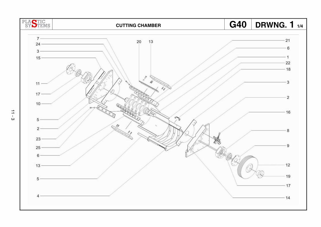
CUTTING CHAMBER G40 DRWNG. 1 1/4
11 - 3
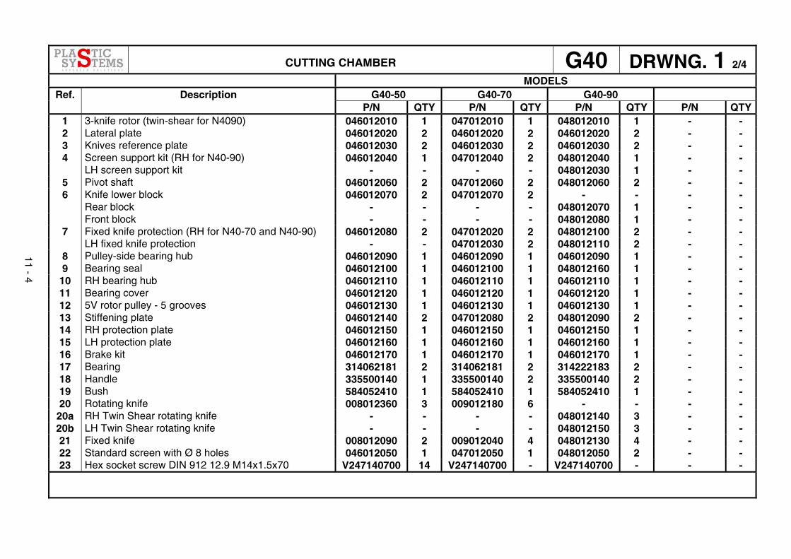
CUTTING CHAMBER G40 DRWNG. 1 2/4 MODELS
G40-50 G40-70 G40-90 Ref. Description P/N QTY P/N QTY P/N QTY P/N QTY
1 3-knife rotor (twin-shear for N4090) 046012010 1 047012010 1 048012010 1 - - 2 Lateral plate 046012020 2 046012020 2 046012020 2 - - 3 Knives reference plate 046012030 2 046012030 2 046012030 2 - - 4 Screen support kit (RH for N40-90) 046012040 1 047012040 2 048012040 1 - - LH screen support kit - - - - 048012030 1 - -
5 Pivot shaft 046012060 2 047012060 2 048012060 2 - - 6 Knife lower block 046012070 2 047012070 2 - - - - Rear block - - - - 048012070 1 - - Front block - - - - 048012080 1 - -
7 Fixed knife protection (RH for N40-70 and N40-90) 046012080 2 047012020 2 048012100 2 - - LH fixed knife protection - - 047012030 2 048012110 2 - -
8 Pulley-side bearing hub 046012090 1 046012090 1 046012090 1 - - 9 Bearing seal 046012100 1 046012100 1 048012160 1 - -
10 RH bearing hub 046012110 1 046012110 1 046012110 1 - - 11 Bearing cover 046012120 1 046012120 1 046012120 1 - - 12 5V rotor pulley - 5 grooves 046012130 1 046012130 1 046012130 1 - - 13 Stiffening plate 046012140 2 047012080 2 048012090 2 - - 14 RH protection plate 046012150 1 046012150 1 046012150 1 - - 15 LH protection plate 046012160 1 046012160 1 046012160 1 - - 16 Brake kit 046012170 1 046012170 1 046012170 1 - - 17 Bearing 314062181 2 314062181 2 314222183 2 - - 18 Handle 335500140 1 335500140 2 335500140 2 - - 19 Bush 584052410 1 584052410 1 584052410 1 - - 20 Rotating knife 008012360 3 009012180 6 - - - -
20a RH Twin Shear rotating knife - - - - 048012140 3 - - 20b LH Twin Shear rotating knife - - - - 048012150 3 - - 21 Fixed knife 008012090 2 009012040 4 048012130 4 - - 22 Standard screen with Ø 8 holes 046012050 1 047012050 1 048012050 2 - - 23 Hex socket screw DIN 912 12.9 M14x1.5x70 V247140700 14 V247140700 - V247140700 - - -
11 - 4

CUTTING CHAMBER G40 DRWNG. 1 3/4
11 - 5
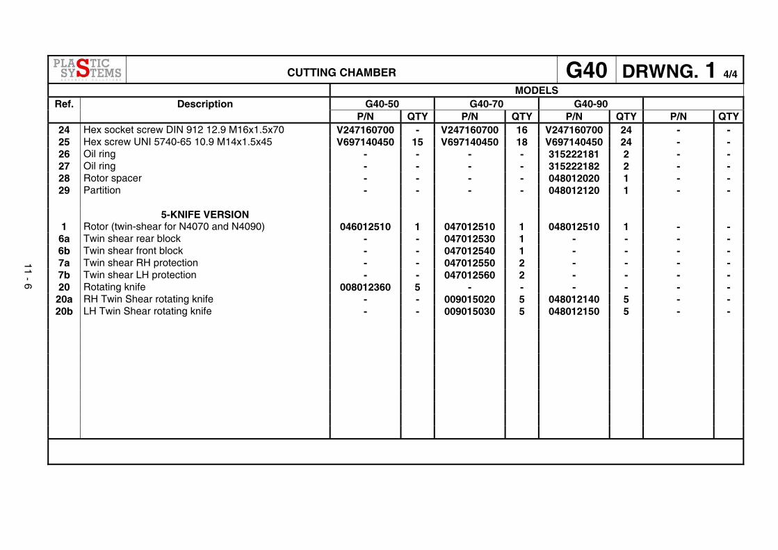
CUTTING CHAMBER G40 DRWNG. 1 4/4 MODELS
G40-50 G40-70 G40-90 Ref. Description P/N QTY P/N QTY P/N QTY P/N QTY
24 Hex socket screw DIN 912 12.9 M16x1.5x70 V247160700 - V247160700 16 V247160700 24 - - 25 Hex screw UNI 5740-65 10.9 M14x1.5x45 V697140450 15 V697140450 18 V697140450 24 - - 26 Oil ring - - - - 315222181 2 - - 27 Oil ring - - - - 315222182 2 - - 28 Rotor spacer - - - - 048012020 1 - - 29 Partition - - - - 048012120 1 - -
5-KNIFE VERSION
1 Rotor (twin-shear for N4070 and N4090) 046012510 1 047012510 1 048012510 1 - - 6a Twin shear rear block - - 047012530 1 - - - - 6b Twin shear front block - - 047012540 1 - - - - 7a Twin shear RH protection - - 047012550 2 - - - - 7b Twin shear LH protection - - 047012560 2 - - - - 20 Rotating knife 008012360 5 - - - - - -
20a RH Twin Shear rotating knife - - 009015020 5 048012140 5 - - 20b LH Twin Shear rotating knife - - 009015030 5 048012150 5 - -
11 - 6

HOPPER BASE KIT G40 DRWNG. 2 1/2
11 - 7
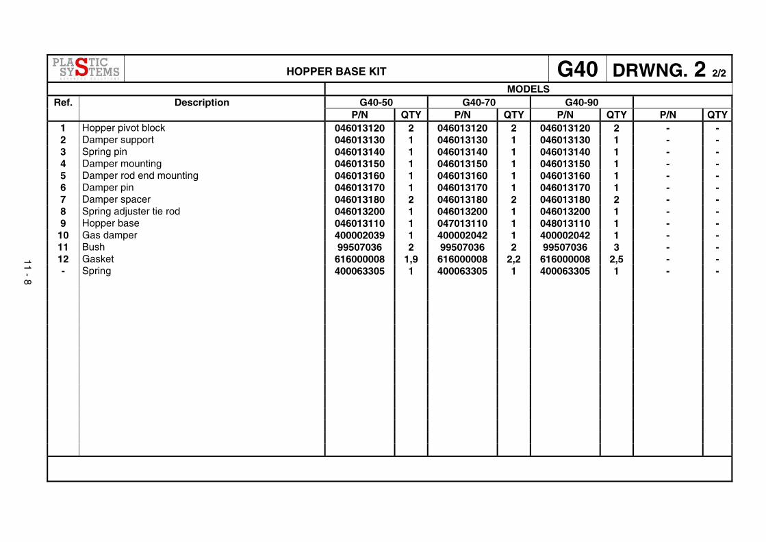
HOPPER BASE KIT G40 DRWNG. 2 2/2 MODELS
G40-50 G40-70 G40-90 Ref. Description P/N QTY P/N QTY P/N QTY P/N QTY
1 Hopper pivot block 046013120 2 046013120 2 046013120 2 - - 2 Damper support 046013130 1 046013130 1 046013130 1 - - 3 Spring pin 046013140 1 046013140 1 046013140 1 - - 4 Damper mounting 046013150 1 046013150 1 046013150 1 - - 5 Damper rod end mounting 046013160 1 046013160 1 046013160 1 - - 6 Damper pin 046013170 1 046013170 1 046013170 1 - - 7 Damper spacer 046013180 2 046013180 2 046013180 2 - - 8 Spring adjuster tie rod 046013200 1 046013200 1 046013200 1 - - 9 Hopper base 046013110 1 047013110 1 048013110 1 - -
10 Gas damper 400002039 1 400002042 1 400002042 1 - - 11 Bush 99507036 2 99507036 2 99507036 3 - - 12 Gasket 616000008 1,9 616000008 2,2 616000008 2,5 - - - Spring 400063305 1 400063305 1 400063305 1 - -
11 - 8
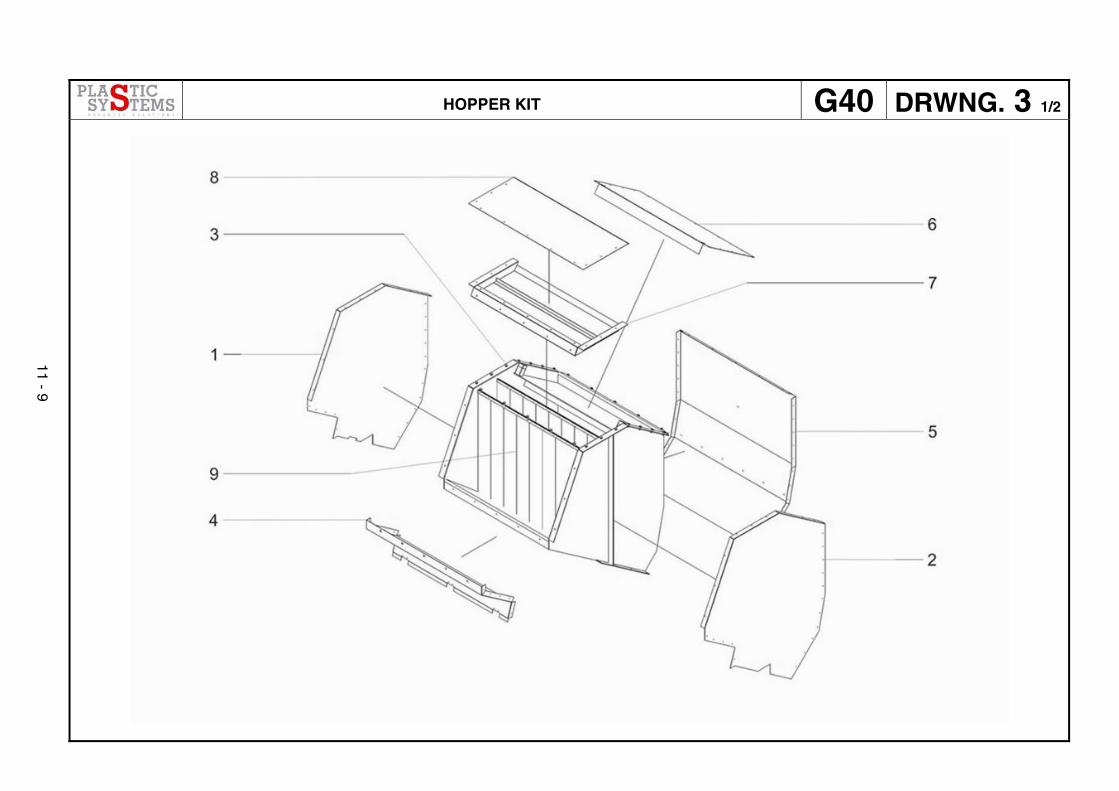
HOPPER KIT G40 DRWNG. 3 1/2
11 - 9
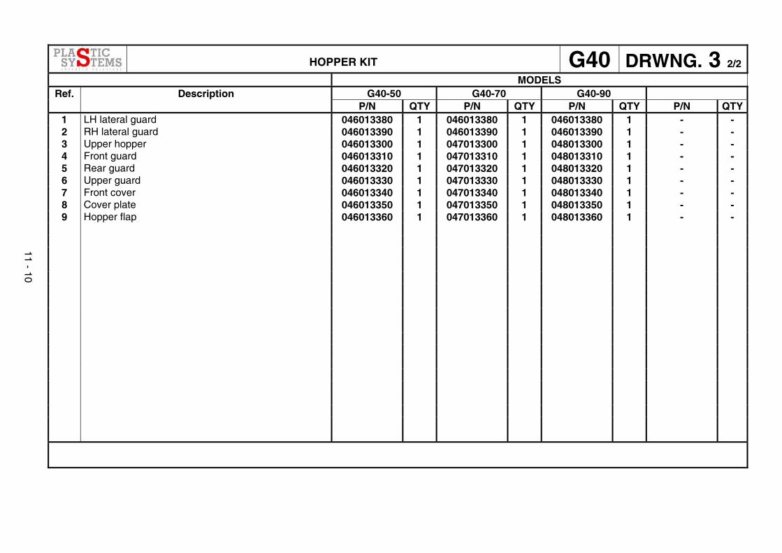
HOPPER KIT G40 DRWNG. 3 2/2 MODELS
G40-50 G40-70 G40-90 Ref. Description P/N QTY P/N QTY P/N QTY P/N QTY
1 LH lateral guard 046013380 1 046013380 1 046013380 1 - - 2 RH lateral guard 046013390 1 046013390 1 046013390 1 - - 3 Upper hopper 046013300 1 047013300 1 048013300 1 - - 4 Front guard 046013310 1 047013310 1 048013310 1 - - 5 Rear guard 046013320 1 047013320 1 048013320 1 - - 6 Upper guard 046013330 1 047013330 1 048013330 1 - - 7 Front cover 046013340 1 047013340 1 048013340 1 - - 8 Cover plate 046013350 1 047013350 1 048013350 1 - - 9 Hopper flap 046013360 1 047013360 1 048013360 1 - -
11 - 10

BASE AND GUARDS KIT G40 DRWNG. 4 1/3
11 - 11

BASE AND GUARDS KIT G40 DRWNG. 4 2/3 MODELS
G40-50 G40-70 G40-90 Ref. Description P/N QTY P/N QTY P/N QTY P/N QTY
1 Latch pin 028014050 3 028014050 3 028014050 3 - - 2 LH support member 046011010 1 046011010 1 046011010 1 - - 3 RH support member 046011020 1 046011020 1 046011020 1 - - 4 LH lateral guard 046011070 1 046011070 1 046011070 1 - - 5 RH lateral guard 046011080 1 046011080 1 046011080 1 - - 6 Guard support angle profile 046011120 2 046011120 2 046011120 2 - - 7 Guard support tube 046011130 2 046011130 2 046011130 2 - - 8 RH front hinge support 046011140 1 046011140 1 046011140 1 - - 9 LH front hinge support 046011150 1 046011150 1 046011150 1 - -
10 Door hinge angle profile 046011160 2 046011160 4 046011160 4 - - 11 Microswitch support 046011180 1 046011180 1 046011180 1 - - 12 Electrical panel support plate 046011190 1 046011190 1 046011190 1 - - 13 Pushbuttons enclosure plate 046011200 1 046011200 1 046011200 1 - - 14 Motor pivot support 046011210 2 046011210 2 046011210 2 - - 15 Motor plate bracket 046011220 2 046011220 2 046011220 2 - - 16 Motor bracket spindle 046011230 1 046011230 1 046011230 1 - - 17 Motor plate 046011240 1 046011240 1 046011240 1 - - 18 Plate adjustment spindle 046011250 1 046011250 1 046011250 1 - - 19 Motor adjustment tie rod 046011260 3 046011260 3 046011260 3 - - 20 Suction closing plate 046011320 1 046011320 1 046011320 1 - - 21 Terminal 046011350 2 046011350 2 046011350 2 - - 22 Spring guide 046011360 1 046011360 1 046011360 1 - - 23 Spring contrast 046011370 1 046011370 1 046011370 1 - - 24 Bayonet fitting 046011390 1 046011390 1 046011390 1 - - 25 Fixed rear guard 046011270 1 047011010 1 048011010 1 - - 26 Mobile rear guard 046011280 1 047011020 1 048011020 1 - - 27 Rear crossbar 046011030 1 047011030 1 048011030 1 - - 28 Central crossbar 046011040 1 047011040 1 048011040 1 - -
11 - 12
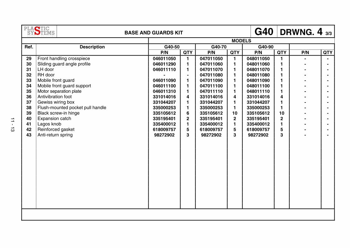
BASE AND GUARDS KIT G40 DRWNG. 4 3/3 MODELS
G40-50 G40-70 G40-90 Ref. Description P/N QTY P/N QTY P/N QTY P/N QTY
29 Front handling crosspiece 046011050 1 047011050 1 048011050 1 - - 30 Sliding guard angle profile 046011290 1 047011060 1 048011060 1 - - 31 LH door 046011110 1 047011070 1 048011070 1 - - 32 RH door - - 047011080 1 048011080 1 - - 33 Mobile front guard 046011090 1 047011090 1 048011090 1 - - 34 Mobile front guard support 046011100 1 047011100 1 048011100 1 - - 35 Motor separation plate 046011310 1 047011110 1 048011110 1 - - 36 Antivibration foot 331014016 4 331014016 4 331014016 4 - - 37 Gewiss wiring box 331044207 1 331044207 1 331044207 1 - - 38 Flush-mounted pocket pull handle 335000253 1 335000253 1 335000253 1 - - 39 Black screw-in hinge 335105612 6 335105612 10 335105612 10 - - 40 Expansion catch 335195401 2 335195401 2 335195401 2 - - 41 Lagos knob 335400012 1 335400012 1 335400012 1 - - 42 Reinforced gasket 618009757 5 618009757 5 618009757 5 - - 43 Anti-return spring 98272902 3 98272902 3 98272902 3 - -
11 - 13
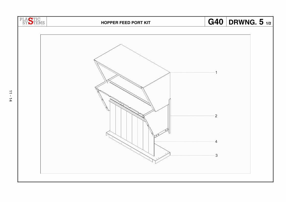
HOPPER FEED PORT KIT G40 DRWNG. 5 1/2
11 - 14
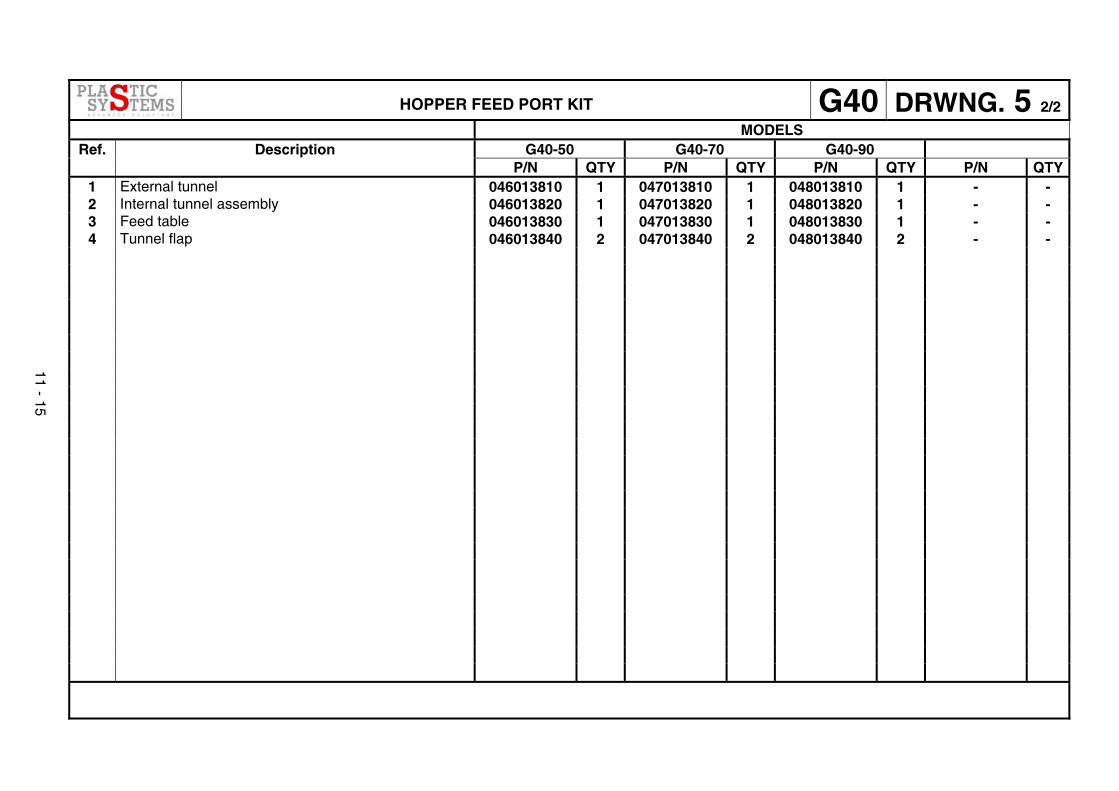
HOPPER FEED PORT KIT G40 DRWNG. 5 2/2 MODELS
G40-50 G40-70 G40-90 Ref. Description P/N QTY P/N QTY P/N QTY P/N QTY
1 External tunnel 046013810 1 047013810 1 048013810 1 - - 2 Internal tunnel assembly 046013820 1 047013820 1 048013820 1 - - 3 Feed table 046013830 1 047013830 1 048013830 1 - - 4 Tunnel flap 046013840 2 047013840 2 048013840 2 - -
11 - 15
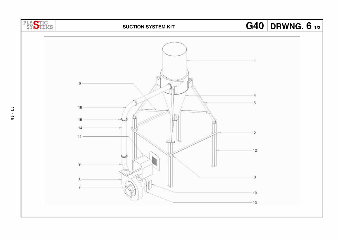
SUCTION SYSTEM KIT G40 DRWNG. 6 1/2
11 - 16
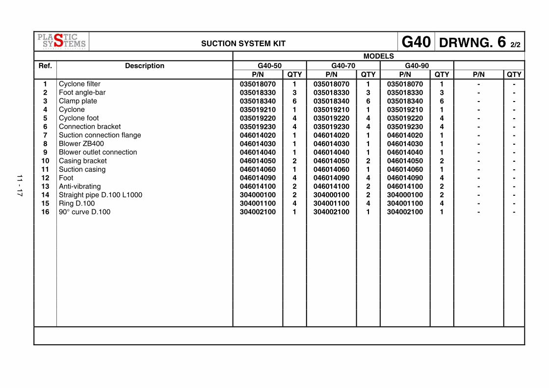
SUCTION SYSTEM KIT G40 DRWNG. 6 2/2 MODELS
G40-50 G40-70 G40-90 Ref. Description P/N QTY P/N QTY P/N QTY P/N QTY
1 Cyclone filter 035018070 1 035018070 1 035018070 1 - - 2 Foot angle-bar 035018330 3 035018330 3 035018330 3 - - 3 Clamp plate 035018340 6 035018340 6 035018340 6 - - 4 Cyclone 035019210 1 035019210 1 035019210 1 - - 5 Cyclone foot 035019220 4 035019220 4 035019220 4 - - 6 Connection bracket 035019230 4 035019230 4 035019230 4 - - 7 Suction connection flange 046014020 1 046014020 1 046014020 1 - - 8 Blower ZB400 046014030 1 046014030 1 046014030 1 - - 9 Blower outlet connection 046014040 1 046014040 1 046014040 1 - -
10 Casing bracket 046014050 2 046014050 2 046014050 2 - - 11 Suction casing 046014060 1 046014060 1 046014060 1 - - 12 Foot 046014090 4 046014090 4 046014090 4 - - 13 Anti-vibrating 046014100 2 046014100 2 046014100 2 - - 14 Straight pipe D.100 L1000 304000100 2 304000100 2 304000100 2 - - 15 Ring D.100 304001100 4 304001100 4 304001100 4 - - 16 90° curve D.100 304002100 1 304002100 1 304002100 1 - -
11 - 17