Embed Size (px)
Citation preview

ThyssenKruppAufzugswerke
OperatingManualDriveTW63


Legal information
All rights reserved © Copyright by ThyssenKrupp Aufzugswerke GmbH Note on industrial property rights ISO 16016 Printed in Germany This document – including excerpts – may only be reprinted or otherwise copied with the express approval in writing of ThyssenKrupp Aufzugswerke GmbH. Any duplication, dissemination or storage on data media unauthorised by ThyssenKrupp Aufzugswerke GmbH is an infringement of copyright and shall give rise to prosecution. Right to make changes of a technical nature reserved We expressly reserve the right to make changes of a technical nature for the purpose of improving our products or enhancing the safety standard - even without a separate announcement. Colouring The colouring of the components used in our documentation is used only for the documentation. Enquire about colours for your products from your ThyssenKrupp Aufzugswerke Sales Partner. Issued by ThyssenKrupp Aufzugswerke GmbH Bernhäuser Strasse 45 73765 Neuhausen a. d. F. Germany E-mail: [email protected] Internet: www.thyssenkrupp-elevator-eli.de


OPERATING MANUAL TW63
ThyssenKrupp Aufzugswerke GmbH
Table of Contents
TW63 drive PAGE
1. Safety 6 1.1 Symbols 6 1.2 Safety instructions 7
2. Product description 10 2.1 Description 10 2.2 Functional description 11
3. Technology 14 3.1 Technical data 14 3.2 Dimensions of machine 15 3.3 Dimensions of machine base frame (optional) 20 3.4 Encoder 21
4. Transport and storage 22 5. Mounting the machine 26
5.1 Connecting the gear drive motors 26 5.2 Terminal connecting plan for DEE motor and magnetic
clamps 27 5.3 Terminal connecting information for motors complying with
BV 6531 - 21 28 5.4 Terminal connecting information for motors complying with
BV 6531 - 22 29 5.5 Terminal connecting information for VFD motors 30 5.6 Fitting the rope guard for traction sheave 31
6. Commissioning 32 6.1 Emergency operation 33
7. Maintenance / Service 34
7.1 Lubrication 35 7.2 Checking the backlash 37 7.3 Replacing brake shoes 38 7.4 Setting braking deceleration 39 7.5 Setting brake shoe stroke and armature base plate 40 7.6 Traction sheave replacement 41 7.7 Motor replacement 42 7.8 Checking for escaping grease / oil 43
8. Special versions (optional) 44 8.1 Brake monitoring circuit 44 9. Appendix 46 9.1 Blocking clamp 46 9.2 Tightening torques - tightness values 47 10. Changes 50 Flexible coupling Encoder
5 09-2012

OPERATING MANUAL TW63 SAFETY
ThyssenKrupp Aufzugswerke GmbH
1. Safety
1.1 Symbols
The following pictograms and designations are used in this operating manual:
Danger
This symbol indicates extreme danger to life and the health of persons. Nonobservance can lead to death or severe injury!
Danger This symbol indicates an immediate danger to the life and health of persons due to electrical current. Hazard warnings must always be observed!
Warning
This symbol warns against imminent danger. Nonobservance can lead to physical injury or extensive damage to property. Warnings must always be observed!
Note
This symbol indicates important information and operating instructions. Nonobservance can lead to damage, danger or malfunctions.
Test/Check
Test steps are specified with this symbol. The test instructions marked in this way must be followed without fail. They contribute to preventing personal injury or damage to property.
6 09-2012

OPERATING MANUAL TW63 SAFETY
ThyssenKrupp Aufzugswerke GmbH
1.2 Safety instructions
Notes regarding this operating manual
A requirement for safe handling and non-disruptive operation of this assembly is knowledge of the fundamental safety regulations. This operating manual contains the most important information that is required to operate the assembly safely. The operating manual, in particular the safety instructions, is to be complied with by all persons who work on this assembly. Furthermore, the rules and regulations covering accident prevention that apply to the installation site are to be complied with.
Obligations of the operator
The operator undertakes only to allow persons to work on the assembly who
• are familiar with the regulations regarding work safety and accident prevention and have been instructed in handling the assembly.
• have read the chapter on safety and the warnings in this operating manual.
Note: Check the safety awareness of the personnel at regular intervals.
Obligations on the part of personnel
Persons assigned to work on subassemblies undertake before starting work to
• observe the regulations regarding work safety and accident prevention.
• read the chapter on safety and the warnings in this operating manual.
Training of the personnel
Only trained and instructed qualified personnel may work on the assembly. The responsibility of the personnel is to be clearly defined for all tasks involving commissioning, operation, maintenance and repair.
Organisational measures
The required personal protective equipment is to be provided by the operator. All existing safety devices are to be tested regularly in accordance with the maintenance plan.
7 09-2012

OPERATING MANUAL TW63 SAFETY
ThyssenKrupp Aufzugswerke GmbH
Informal notes on the safety measures
• The operating manual is to be kept permanently at the usage site of the installation.
• Complementary to the operating manual, the generally applicable and local regulations for accident prevention and environmental protection are to be provided and complied with.
• Legally prescribed safety instructions are to be provided for the users at clearly visible positions.
• Keep all safety and hazard warnings on the installation in a legible condition.
Use in line with intended purpose
The TW63 has been constructed using state-of-the-art technology and in line with the recognised technical safety regulations. The TW63 may only be
• deployed in line with the intended purpose and
• used when all the technical safety features are in perfect condition
The exclusive intended purpose of the TW63 is to drive elevator cars. Any other or additional form of use shall be regarded as non-compliant with the intended use. THYSSENKRUPP AUFZUGSWERKE GmbH shall not be liable for any damage arising from such use and any damage arising due to operator errors. Proper use in line with the intended purpose also includes
• observance of all instructions in the operating manual and
• adherence to commissioning instructions, system description and inspection and maintenance work.
Warranty and liability
As a general principle, the 'General Terms of Sale and Delivery' of THYSSENKRUPP AUFZUGSWERKE GmbH apply. Warranty and liability claims in the event of personal injury and damage to property shall be excluded if they arise due to any of the following causes:
• Improper use that is not in line with the intended purpose of the TW63
• Installation, commissioning, operation and maintenance of the TW63 that is not in line with accepted technical principles
• Operation of the TW63 machine with defective and/or
non-operative safety and protective devices
• Nonobservance of the instructions in the operating manual with regard to
transport, storage, installation, commissioning, operation and maintenance
of the TW63
• Constructional changes to the TW63 performed by the operator
• Changes to the drive ratios (power output etc.) performed by the operator
• Deficient monitoring of parts that are subject to
wear
• Repairs that are carried out improperly
8 09-2012

OPERATING MANUAL TW63 SAFETY
ThyssenKrupp Aufzugswerke GmbH
• Cases of catastrophe due to third-party interference and force majeure.
Constructional changes to the TW63 performed by the operator
The TW63 is set at the plant and delivered ready for operation. Important: The oil necessary for operation has been added at the plant! Check this before the first commissioning by looking at the oil gauge glass (see chapter 7 ). If changes are made to the machine, the entire warranty of THYSSENKRUPP AUFZUGSWERKE GmbH shall become null and void.
Dangers in handling the TW63
The traction sheave and the handwinding wheel of the TW63 are designed without a safety cover and may only be used in an enclosed room. It must be ensured when persons are in the machine room that there is adequate safety clearance to all revolving (marked in yellow) parts. Note: With the vertical version, do not place any objects (e.g. tools etc.) on the handwinding wheel, as there is a risk of injury as a result of parts being thrown. In the event of improper use, there is a risk of personal injury or to the life of the user or third parties, or impairment on the assembly or other assets can arise. Malfunctions that can impair safety are to be rectified immediately.
9 09-2012

OPERATING MANUAL TW63 PRODUCT DESCRIPTION
ThyssenKrupp Aufzugswerke GmbH
2. Product description
2.1 Description
1 Actual-value sensor 9 Rope guard
2 Handwinding wheel / flywheel rim 10 Machine base frame (optional)
3 Forced ventilation (optional) 11 Name plate
4 Motor 12 Gear housing
5 Armature base plate 13 Rope guard carrier
6 Brake shoe 14 Brake monitoring switch
7 Traction sheave 15 Motor terminal box
8 Disc on the traction sheave shaft 16 Brake magnet
Versions: The following version of the machine can be chosen depending on customer needs: gear reduction, traction sheave version, motor version, motor arrangement (vertical / horizontal), encoder version
1 2 3 4
5
6
7
8
9
15
14
13
12
11
9
10
Fig. 2.1 Version TW63 V
(vertical motor arrangement)
10 09-2012
OPERATING MANUAL TW63 PRODUCT DESCRIPTION
ThyssenKrupp Aufzugswerke GmbH
2.2 Functional description
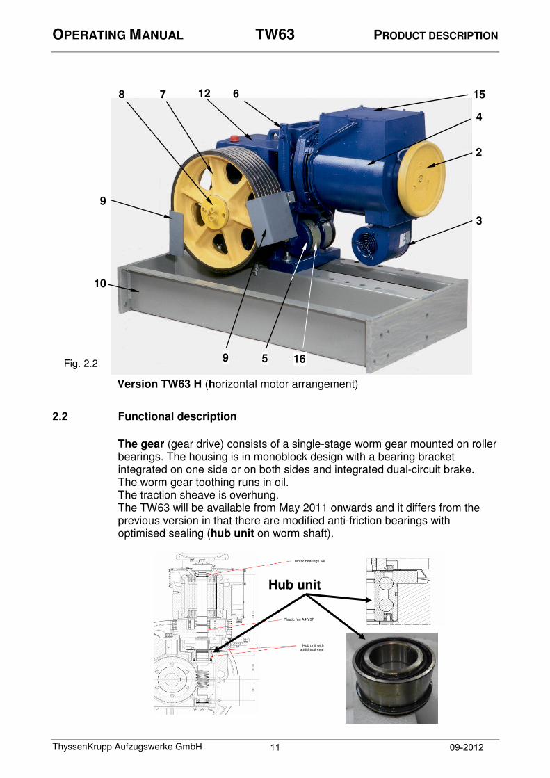
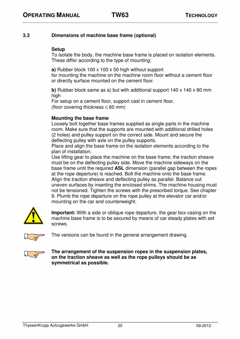
The gear (gear drive) consists of a single-stage worm gear mounted on roller bearings. The housing is in monoblock design with a bearing bracket integrated on one side or on both sides and integrated dual-circuit brake. The worm gear toothing runs in oil. The traction sheave is overhung. The TW63 will be available from May 2011 onwards and it differs from the previous version in that there are modified anti-friction bearings with optimised sealing (hub unit on worm shaft).
Fig. 2.2
Version TW63 H (horizontal motor arrangement)
7 8 6 15
4
2
3
5 9
10
9
12
16
Hub unit
Motor bearings A4
Plastic fan A4 V3F
Hub unit with additional seal
11 09-2012

OPERATING MANUAL TW63 PRODUCT DESCRIPTION
ThyssenKrupp Aufzugswerke GmbH
Depending on the version, the drive comes from a three-phase motor standing vertically on the gear or flange-connected horizontally on the gear to the worm shaft, via worm wheel, traction sheave shaft to the traction sheave.
Brake:
The dual circuit shoe brake is spring actuated. Two independently acting brake shoes press the brake lining onto the brake disc with spring force preset on the system. The braking force is configured in such a way that one of the brake blocks is sufficient to bring an elevator car loaded with full weight to a standstill. The brake is released by electrically operated magnetic clamps. In the case of manual operation, the enclosed brake release lever must be applied to the cast-on recesses of the ends of the brake shoes. Pressing in the direction of the machine (see Fig. 2.2.1 in the direction of the arrow) presses the brake shoes apart, triggering the brake.
1
1 Brake shoes
2 Brake release lever
2
Fig. 2.2.1
12 09-2012

OPERATING MANUAL TW63 PRODUCT DESCRIPTION
ThyssenKrupp Aufzugswerke GmbH
Traction sheave:
The one-part traction sheaves are fastened overhung on the drive shaft by using a cone (1:15) and a mounting plate including 3 screws (M16-8.8 microencapsulated with locking washer).
Designation Unit Technical data
Machine version Standard
SA9 - SA9
Diameter - DT mm 450 510 590 520 675
Rim width - B mm 132 110 96
Max. number of grooves - z x d
8 x 8 8 x 8
5 x 13
6 x 8
7 x 10/11 7 x 10/11 5 x 10/11
6 x 12 4 x 12
Groove type Seat / vee groove
Vee groove angle ° Depends on project specs
1)
Vee groove K40 2)
Weight kg 50 60 70 50 70
Material Specially alloyed EN-GJL 250 1)
Version in accordance with a factory standard 60 300 50 00 0 with hardened groove flanks (min. 50 HRc)
2) Standard version
TW63_30301_ENG
Table 2.2.1
13 09-2012

OPERATING MANUAL TW63 TECHNOLOGY
ThyssenKrupp Aufzugswerke GmbH
3. Technology
3.1 Technical data
Permitted load of the traction sheave shaft: for standard version max. 43 kN
for SA 9 (extended wheel shaft) max. 41 kN Axle distance: 155 mm Brake magnet connection:
In the case of the TW63 machine, the Connection values magnetic clamp: two magnets are connected in succession.
Rated voltage: 50 V
Power supply Rated current: 1.1 A for field forcing device: 200 V Type of protection: IP65 for retentive voltage: 100 V
Magnetic clamp nominal force: 2* 2500 N Max. braking torque: approx. 2* 90 Nm Brake disc diameter: 200 mm
Weight: Standard version of motor in A4 design
Gear drive (without motor and traction sheave) 250 kg Gear drive SA 9 (without motor and traction sheave) 290 kg Gear drive (with motor and traction sheave) approx. 370 kg Gear drive SA 9 (with motor and traction sheave) approx. 410 kg Traction sheave according to order 450 - 675 mm dia. approx. 50 - 70 kg
14 09-2012

OPERATING MANUAL TW63 TECHNOLOGY
ThyssenKrupp Aufzugswerke GmbH
3.2 Dimensions of machine
3.2.1 Version with motor type A4 / vertical motor position
1 Air guidance, motor 2 Centre of gravity
Fig. 3.2.1
15 09-2012

OPERATING MANUAL TW63 TECHNOLOGY
ThyssenKrupp Aufzugswerke GmbH
3.2.2 Version with motor type A4 / horizontal motor position
1 Centre of gravity 2 Pictured: traction sheave position - left / right is mirror-inverted to A-A
3 With oil drain at side (SA11)
2
3 Fig. 3.2.2
16 09-2012

OPERATING MANUAL TW63 TECHNOLOGY
ThyssenKrupp Aufzugswerke GmbH
3.2.3 Version with motor type IMB5/V1
1 Length of intermediate flange for motor in line with: BV6530-06 / Sheet 1: 0 mm BV6530-06 / Sheet 6: 64 mm
Fig. 3.2.3
1
17 09-2012

OPERATING MANUAL TW63 TECHNOLOGY
ThyssenKrupp Aufzugswerke GmbH
3.2.4 Version with emergency brake, NBS
1 With Warner brake SZ1700/1700 Nm
2 With Mayr brake RSO800/2200 Nm
Fig. 3.2.4
1
2
18 09-2012

OPERATING MANUAL TW63 TECHNOLOGY
ThyssenKrupp Aufzugswerke GmbH
3.2.5 Version for traction sheave in the shaft - SA9
1 Dimension for middle of self-aligning bearing
2 Dimension for middle of bearing housing
3 With vertical motor position 4 With horizontal motor position
Fig. 3.2.5
4 3
2
1
19 09-2012
OPERATING MANUAL TW63 TECHNOLOGY
ThyssenKrupp Aufzugswerke GmbH
3.3 Dimensions of machine base frame (optional)
Setup To isolate the body, the machine base frame is placed on isolation elements. These differ according to the type of mounting:
a) Rubber block 100 x 100 x 50 high without support for mounting the machine on the machine room floor without a cement floor or directly surface mounted on the cement floor.
b) Rubber block same as a) but with additional support 140 x 140 x 80 mm high For setup on a cement floor, support cast in cement floor.
(floor covering thickness ≤ 60 mm) Mounting the base frame Loosely bolt together base frames supplied as single parts in the machine room. Make sure that the supports are mounted with additional drilled holes (2 holes) and pulley support on the correct side. Mount and secure the deflecting pulley with axle on the pulley supports. Place and align the base frame on the isolation elements according to the plan of installation. Use lifting gear to place the machine on the base frame; the traction sheave must be on the deflecting pulley side. Move the machine sideways on the base frame until the required ASL dimension (parallel gap between the ropes at the rope departure) is reached. Bolt the machine onto the base frame. Align the traction sheave and deflecting pulley as parallel. Balance out uneven surfaces by inserting the enclosed shims. The machine housing must not be tensioned. Tighten the screws with the prescribed torque. See chapter 9. Plumb the rope departure on the rope pulley at the elevator car and/or mounting on the car and counterweight. Important: With a side or oblique rope departure, the gear box casing on the machine base frame is to be secured by means of car steady plates with set screws. The versions can be found in the general arrangement drawing. The arrangement of the suspension ropes in the suspension plates, on the traction sheave as well as the rope pulleys should be as symmetrical as possible.
20 09-2012
OPERATING MANUAL TW63 TECHNOLOGY
ThyssenKrupp Aufzugswerke GmbH
3.4 Encoder
Overview: The following encoders are available for the TW63 Distinction by type depending on the control system deployed
1. TTL for Thyssen control system CPI
for v < 1.5 m/s with 1024 impulses
for v ≥ 1.5 m/s with 4096 impulses Connection takes place with SUB-D 9 ribbon connector with knurled screw UNC4-40
2. HTL for third-party control systems or third-party converters with 2 x 64 impulses Connection takes place with insulation stripped and wire end sleeves attached. 3. HTL for third-party control systems or third-party converters with 1024 impulses Connection takes place with insulation stripped and wire end sleeves attached.
4. Sine, cosine for third-party control systems or third-party converters with 1024 impulses Connection takes place with insulation stripped and wire end sleeves attached. Comply with the manufacturer's instructions in chapter 9
21 09-2012

OPERATING MANUAL TW63 TRANSPORT AND STORAGE
ThyssenKrupp Aufzugswerke GmbH
4. Transport and storage
Packaging: The gear box casing is bolted directly onto the special pallet. Gear box casing is bolted directly onto the special pallet. Wood support under
non-TK motor. Gear box casing is bolted with an intermediate wood layer onto the special
pallet. Wood support under non-TK motor. Wood backing spacers under traction
sheave
Fig. 4.1 Fig. 4.2
Fig. 4.3 Fig. 4.3
Fig. 4.5 Fig. 4.6
22 09-2012

OPERATING MANUAL TW63 TRANSPORT AND STORAGE
ThyssenKrupp Aufzugswerke GmbH
Further packaging depends on the order and is country-specific (air/sea/land freight). Transport: Transport must be effected in compliance with the safety regulations and observing the centre of gravity of the machine.
Important: Machine is filled with oil. It may only be transported and stored upright. Fork-lift truck transport:
• For transport, always pick up the transport pallet, not the machine itself, with the forklift. Secure the load against falling over.
• Pay attention to protruding parts! Danger of injury and damage!
• Crane transport:
• Do not walk underneath suspended loads!
• Secure the machine without base frame with cable to the transport hanger. In the case of a machine that is mounted on the machine base frame, attach a transport rope to the base frame.
• Secure the machine against slipping and falling over.
Fig. 4.7
Transport hanger
23 09-2012

OPERATING MANUAL TW63 TRANSPORT AND STORAGE
ThyssenKrupp Aufzugswerke GmbH
In the case of vertical transport with non-ThyssenKrupp motors, remove the handwinding wheel and screw in an M12 eyebolt.
Use suitable lifting gear to lift slowly without jerking.
Once transport has been completed, the handwinding wheel must be remounted. Rope attachment: In the case of a machine without machine base frame, attach the transport rope to the transport hanger.
Pay attention to the picture symbols on the packaging or elsewhere.
This way up Fragile goods Protect against water
Protect against heat
Hand hooks prohibited
Attach here
Dimensions and weight The weight data is specified on the packaging on a label below the transport hangers. Please refer to the delivery note for the dimensions. Rough specifications, see chapter 2.3 'Technical data'.
Fig. 4.8 Fig. 4.9
24 09-2012

OPERATING MANUAL TW63 TRANSPORT AND STORAGE
ThyssenKrupp Aufzugswerke GmbH
Check on acceptance by the recipient
The delivered parts and their packaging are to be checked for completeness, damage or other conspicuous features.
Reporting and documenting damage in transit
On delivery, make sure that no damage in transit has occurred.
Any damage that is determined is to be documented immediately (sketch, photo, description of the damage).
Forward the corresponding documents without delay to THYSSENKRUPP AUFZUGSWERKE GmbH.
Unpacking
Dispose of packaging materials in an environmentally compatible manner or reuse them.
Specific transport equipment and shipping braces remain with the customer.
Intermediate storage
If the assembly is not installed immediately after delivery, it must be stored carefully in a protected location. On covering, attention is to be paid to ensuring that no condensation can form and that no moisture can penetrate.
The assembly must not be stored outdoors. Bare parts have no long-term preservation.
Ambient conditions
The environment at the final location (moisture, temperature) must correspond to normal indoor climate conditions for machine and pulley rooms. (According to EN 81, between +5°C and +40°C)
25 09-2012

OPERATING MANUAL TW63 MOUNTING THE MACHINE
ThyssenKrupp Aufzugswerke GmbH
5. Mounting the machine
Depending on the scope of the order, the TW63 gear drive is delivered with machine base frame and deflecting pulley. The base frame is installed and set up depending on the customer on supports, beams, a concrete pedestal or directly cast in concrete in the machine room floor. For installation and mounting of the base frame supports, a drawing and parts list are enclosed with the base frame.
Important: Use the enclosed mounting parts to mount the base frame according to the drawing. Comply with the specified tightness and the corresponding tightening torques. See details in chapter 9.1.
In order to comply with regulations for noise abatement and sound transmission, isolation elements are to be inserted between the frame supports and the ground. The number of rubber elements is based on the total weight load. The required individual load should be between 7 KN and 12 KN per element. The location and arrangement of the rubber elements can be found in the plan of installation. Note: On arrangement of the supports, it is to be taken into account that the overall centre of gravity lies within the rubber elements (also in the case of elevator car suspension on the deflecting pulley side). If the supporting surface of the machine base frame is cast as a cement floor,
the floor thickness should be ≤ 60 mm. Isolation elements with supports (80 mm high) are to be inserted. Part of the base is also to be cast in the floor. You will find assembly instructions and data for the machine base frame in chapter 3, Aligning the machine The machine is to be set up according to the plan of installation (drawing). The rope departure from the traction sheave is to be aligned plumb to the elevator car mounting or the elevator car rope pulley and the counterweight according to the drawing. With load applied to the ropes, the machine should be aligned vertically on its installation surface. Irregularities are to be balanced out by inserting shims under the floor support.
SA9 traction sheave in the shaft, machine with extended traction sheave shaft and pedestal bearing.
Important: On setting up a gear drive with pedestal bearing, it must be ensured without fail that
• the compensating supports are mounted and secured according to instructions
• the traction sheave shaft is aligned horizontally
• the bearings of the machine and the outside bearing are exactly aligned
5.1 Note on connecting motors
Connecting the motor: on connecting the motor, the enclosed terminal connecting plan in the motor terminal box and/or the terminal connecting plan and corresponding building codes are to be complied with.
26 09-2012

OPERATING MANUAL TW63 MOUNTING THE MACHINE
ThyssenKrupp Aufzugswerke GmbH
5.2 Terminal connecting plan for DEE motor and magnetic clamps
Anschlussplan = terminal connection plan = schéma de raccordement Anschlusskasten Motor / terminal box motor / Boîte à bornes du moteur
Klemmenleiste Terminal block Réglette de raccordement DEE 132 / 140
ACHTUNG! - N.B. - ATTENTION ! An den Klemmen der Kaltleiter keine Spannung größer als 2,5V anlegen! Do not apply more than 2.5V at the terminals of the PTC thermistors! Ne pas appliquer de tension supérieure à 2,5V aux bornes des résistances PTC !
Kaltleiter PTC thermistors Résistances PTC
N BM
Magnetic clamp connection
Motor connection
Fig. 5.2.1
27 09-2012

OPERATING MANUAL TW63 MOUNTING THE MACHINE
ThyssenKrupp Aufzugswerke GmbH
5.3 Terminal connecting information for motors complying with BV 6531 – 21 for pole-changing three-phase motors, type A4
S1 Normally open contact in the winding
RS Min. 22 Ω, max. 47 Ω
CS Min. 0.22 µF/250 V~, max. 0.47 µF/250 V~
CA Starting capacitor for fan
RB Varistor SIOV-S14K275
28 09-2012

OPERATING MANUAL TW63 MOUNTING THE MACHINE
ThyssenKrupp Aufzugswerke GmbH
5.4 Terminal connecting information for motors complying with BV 6531 – 22 for three-phase motors with direct current brake winding, type A4
S1 Normally open contact in the winding
RS Min. 22 Ω, max. 47 Ω
CS Min. 0.22 µF/250 V~, max. 0.47 µF/250 V~
CA Starting capacitor for fan
RB Varistor SIOV-S14K275
The low speed winding is to be designed as a direct current winding or placed in a brake in-line circuit.
29 09-2012

OPERATING MANUAL TW63 MOUNTING THE MACHINE
ThyssenKrupp Aufzugswerke GmbH
5.5 Terminal connecting information for VFD motors for special motors, B5 design
Kaltleiter PTC thermistors
=
Résistances PTC
Achtung! - Attention ! An die Klemmen der Kaltleiter keine Spannung größer als 2,5V anlegen Do not apply more than 2.5V at the terminals of the thermistors. Ne pas appliquer de tension supérieure à 2,5V aux bornes des résistances PTC !
Bremswicklung Brake winding Bobinage du frein Schaltung abhängig von der Wicklungs-ausführung.
Schaltung nach Angabe am Leistungsschild. Connection as stated on the rating plate. Branchement suivant indications sur la plaque signalétique.
Fre
mdbe
lüftun
g
Forc
ed v
entila
tio
n
Ventila
tion e
xte
rne
Drehzahlgeber Speed encoder Tachymètre
3 * UK 16
Isola
ting d
isc
Star circuit
RB - varistor SIOV - S14K27
The brake magnets must be placed in a circuit in the separate terminal box of the gear drive (SA12)
Delta Triangle
Hohe Drehzahl
Zum Regelgerät
High speed To the control
device Grande vitesse Vers le
régulateur
30 09-2012

OPERATING MANUAL TW63 MOUNTING THE MACHINE
ThyssenKrupp Aufzugswerke GmbH
5.6 Fitting the rope guard for traction sheave
Use the enclosed screws to bolt the rope guard onto the rope guard carrier. Pivot the rope guard carrier to set the guard is such a way that the gap between the rope and guard on the rope run-in and run-out side of the traction sheave is as small as possible (1 - 2 mm). With inclined pulling, adapt the location of the rope guard carrier by remounting the changed rope pull direction. Note: Tighten the securing bolts of the rope guard carrier on the gear drive after alignment with the prescribed torque. Tightening torque, see table in the Appendix of the operating manual.
1 Rope guard carrier 2 Rope guard
Important: For machines with rope run-in direction of 0 - 90° above the horizontal (e.g.: machine arrangement up/down beside), an additional rope guard is required to prevent the entry of foreign bodies between the rope and groove. If the rope run-in zone is protected within the machine base frame, the function "protection against injury" is not required.
Note: For SA9 traction sheave in the shaft, no rope guard is fitted at the plant.
max. 1 - 2 mm
2
(Fig. W191) Fig. 5.6.1
Fig. 5.6.2
2
1 1
31 09-2012

OPERATING MANUAL TW63 COMMISSIONING
ThyssenKrupp Aufzugswerke GmbH
6. Commissioning
Before commissioning the machine, the following points should be checked and carried out:
• Safety, auxiliary and installation tools removed from the danger zone
• Check the setup of the machine, base frame, pedestal and rope departure
• Oil drain pipe mounted and closed off with cap
• Gear oil level checked
• Mounting of the machine and base frame checked
• With a side or oblique rope departure, gear box casing secured against moving with steady plates and set screws
• Bolts tightened and secured with the prescribed torque (see table 'Tightening torques', 9.1)
• Brake block stroke and setting checked
• With SA3, setting and function of the brake test switch checked
• Brake test carried out with one brake block in each case
• Function of handbrake release checked
• Rope guard fitted and distance to traction sheave set
• Power connections and earthing of motor, forced ventilation and brake magnet connected and secured
• Direction arrow (Up / Down) attached above traction sheave and clearly visible on the motor near the handwinding wheel according to the direction of travel
Note: If the traction sheave and rope pulley are delivered separately, they are to be mounted properly. If the machine was dismantled due to weight, transport or space, removed parts are to be reassembled to their original state and the mounting parts tightened with the corresponding tightening torque (see table 'Tightening torques', 9.1).
For assembly, use only original construction and mounting parts from ThyssenKrupp Aufzugswerke GmbH, as otherwise no warranty can be provided.
32 09-2012

OPERATING MANUAL TW63 COMMISSIONING
ThyssenKrupp Aufzugswerke GmbH
6.1 Emergency operation
The TW63 is equipped for emergency operation with a handwinding wheel
and a brake release lever that is delivered separately.
The brake release lever is to be applied to the cast-on recesses of the ends
of the brake blocks (see Fig. 6.1). Pressing the levers together presses the
brake blocks apart, opening the brake.
For emergency rescue of trapped persons, the handwinding wheel might also
have to be moved to bring the elevator car into the nearest landing.
Depending on the load, the elevator car can begin to move quickly after
opening the brake. Immediately let go of the handwinding wheel and control
the speed of the elevator car by pressing the brake release lever with varying
degrees of force.
Important: If the handwinding wheel is used for installation and maintenance
purposes
(e.g. "drawing out of the safety gear"), the person carrying out the work must
have a secure footing and stance. If the electrical recall is operated
simultaneously, there is a risk of injury.
1 Brake shoes
2 Brake release lever
Fig. 6.1
1
2
33 09-2012

OPERATING MANUAL TW63 MAINTENANCE / SERVICE
ThyssenKrupp Aufzugswerke GmbH
7. Maintenance / service
Maintenance period: Maintenance of the machine should take place within the framework of central maintenance of the elevator, at least once a year. Note: Commissioning and maintenance work may only be carried out by trained and instructed qualified personnel.
All laws and regulations for elevator systems as well as accident prevention regulations must be known and complied with.
More details on the sequence, settings and data can be found in Chapter:
Check the oil level; top up if necessary 7 Change the oil (when the change date is reached) 7 Check the brake shoes for wear; the remaining lining thickness
must be at least 3 mm 7
Check the brake setting; the block stroke should be 0.3 + 0.1 mm
7
Check the braking deceleration 7 Check the armature base plate setting and its ease of movement 7
Check worm gear toothing for wear Check the backlash between the worm shaft and worm wheel,
0.04 mm to 0.12 mm at 20° C 7
Check groove profile on the traction sheave for damage and wear Check secure seating of bolts of the traction sheave mount 9 Check pulley grooves for damage and wear Check proper and adequate condition and safety of electrical
connections
Check that protective and safety devices are present and
correctly set
34 09-2012
OPERATING MANUAL TW63 MAINTENANCE / SERVICE
ThyssenKrupp Aufzugswerke GmbH
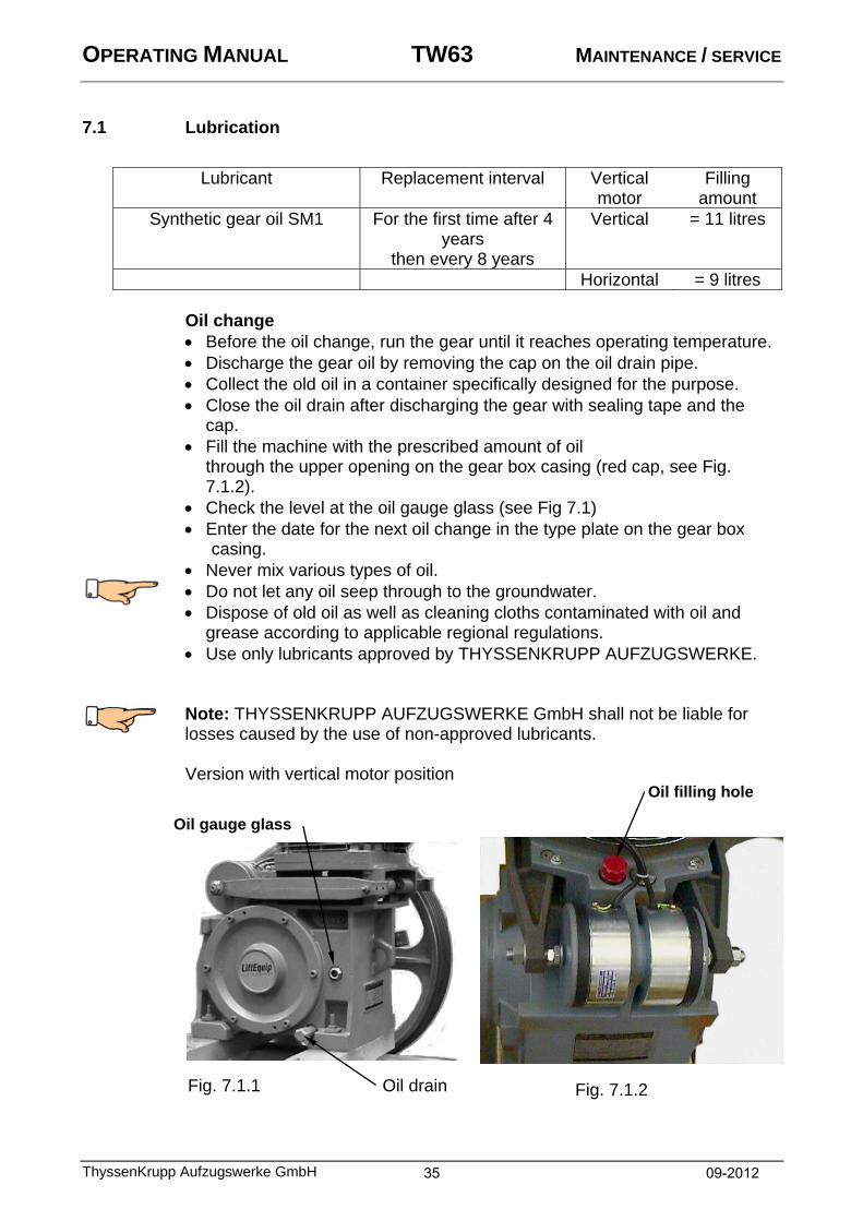
7.1 Lubrication
Lubricant Replacement interval Vertical motor
Filling amount
Synthetic gear oil SM1 For the first time after 4 years
then every 8 years
Vertical = 11 litres
Horizontal = 9 litres Oil change
Before the oil change, run the gear until it reaches operating temperature. Discharge the gear oil by removing the cap on the oil drain pipe. Collect the old oil in a container specifically designed for the purpose. Close the oil drain after discharging the gear with sealing tape and the
cap. Fill the machine with the prescribed amount of oil
through the upper opening on the gear box casing (red cap, see Fig. 7.1.2).
Check the level at the oil gauge glass (see Fig 7.1) Enter the date for the next oil change in the type plate on the gear box
casing. Never mix various types of oil. Do not let any oil seep through to the groundwater. Dispose of old oil as well as cleaning cloths contaminated with oil and grease according to applicable regional regulations. Use only lubricants approved by THYSSENKRUPP AUFZUGSWERKE. Note: THYSSENKRUPP AUFZUGSWERKE GmbH shall not be liable for losses caused by the use of non-approved lubricants.
Version with vertical motor position
Fig. 7.1.1
Oil filling hole
Fig. 7.1.2
Oil gauge glass
Oil drain
35 09-2012

OPERATING MANUAL TW63 MAINTENANCE / SERVICE
ThyssenKrupp Aufzugswerke GmbH
Version with horizontal motor position
1 Oil filling hole 2 Oil gauge glass 3 Oil drain
Checking the oil level: The oil level must be +/- 5 mm from the middles of the gauge glass. When topping up, the machine should remain at a standstill for a certain period ( out of service for approx. 5 minutes). The drive is filled with oil at the plant.
1 2 3
Oil level at middle of gauge glass +/- 5 mm
Fig. 7.1.4
Fig. 7.1.3
36 09-2012

OPERATING MANUAL TW63 MAINTENANCE / SERVICE
ThyssenKrupp Aufzugswerke GmbH
7.2 Checking the backlash
Wear enlarges the backlash on the worm drive between the worm wheel and worm shaft. If the wear limit value (backlash) of 1.5 mm is reached, the gear drive can no longer be deployed for safety reasons. Replace the gear drive.
Measurement possibility: Take the load off the gear drive; (remove ropes from the traction sheave) Run the measurement with the brake closed Fit a dial gauge to the traction sheave; e.g. screw clamp Specify the measured radius (M) and mark the measuring point The radius ( r ) for the TW63 = 130 mm Attach a dial gauge with magnet stator at the gear drive housing and align
to the measuring point (M). Turn the traction sheave by hand until the dial gauge pointer moves. Move the traction sheave back and forth until resistance is felt in both
directions. The tooth flanks of the worm wheel should have a load of approx. 20 - 50 N.
Read off the dial gauge (ME). Use the formula below to calculate the backlash. This measurement is to be carried out in at least three different positions!
Backlash = ME * r
M M = radius ME = measurement result r = radius of worm wheel All dimensions in mm
Fig. 7.2.1
Traction sheave
Worm wheel
Dial gauge
37 09-2012

OPERATING MANUAL TW63 MAINTENANCE / SERVICE
ThyssenKrupp Aufzugswerke GmbH
7.3 Replacing brake shoes
Note: With a remaining lining thickness of less than or equal to 3 mm or if the linings are damaged (e.g. glazing), the brake linings must be replaced.
Before starting work, secure the counterweight and elevator car; switch off the power to the installation.
Loosen the nuts on the tension springs and remove. Remove the bolt locking screw and brake block pins. Remove one brake block; mount the armature base plate on new brake
blocks. In doing so, lightly grease the rubbing surface between the armature base plate and armature screw.
Check the ease of movement of the armature base plate; adjust if necessary. It should be possible to move the armature base plate with low resistance on the screw.
Secure setting by tightening the lock nuts. Install the pre-assembled brake blocks; do not tighten the nuts on the
tension springs. Important: The thread on the brake block pins must be on the outside on installation, as the pin can otherwise no longer be pulled out.
Pretension the brake tension springs to a maximum of 13.5 mm. (approx. 11 revolutions of the lock nuts)
Set the brake block stroke by adjusting the armature base plate screw on the brake block. The brake block stroke should be 0.3 mm + 0.1 mm, measured to the middle of the brake disc.
Change and set the second brake shoe in the same way. After replacement of the brake blocks, run the lift with return and observe
whether the both brake blocks open uniformly. Check the stroke paths and deceleration; if required, adjust.
Fig. 7.3.1: Brake shoe setting, illustration without motor and traction sheave
1 Worm shaft 2 Brake disc 3 Magnetic clamp 4 Cover ring 5 Armature base plate 6 Armature base plate
screw 7 Brake shoes 8 Dial gauge 9 Tightening screw
Stroke 0.3 + 0.1 mm
1 2 3
4
5
6
7
8
9
38 09-2012

OPERATING MANUAL TW63 MAINTENANCE / SERVICE
ThyssenKrupp Aufzugswerke GmbH
7.4 Setting braking deceleration
The brake adjustment is to be carried out only with one effective brake block with the elevator car loaded with the rated load on a descending run (full down) or with an empty elevator car on an ascending run (empty up) according to the deceleration values in the table below.
The braking torque must be set on uniformly on both brake blocks by pretensioning the brake spring depending on the installation.
Machine with
flywheel mass Machine with
handwinding wheel
V m/s 0.63 1.25 0.63 1.25 1.25 - a (full down) m/s² 0.2 0.3 0.3 0.4 0.50 - a (empty up) m/s² 0.4 0.5 0.5 0.6 0.75
Table: Brake deceleration values
1 Brake shoe pin 7 Washer 2 Locking screw with disc 8 Lock nuts 3 Oil ventilation 9 Armature screw 4 Control opening 10 Armature base plate 5 Brake shoes 11 Cover ring 6 Rubber disc 12 Magnetic clamp
12
1
11
10
8
9
8
7
6
5
2 3 4 2 1
Fig. 7.4.1
Fig. TW63 V
39 09-2012

OPERATING MANUAL TW63 MAINTENANCE / SERVICE
ThyssenKrupp Aufzugswerke GmbH
7.5 Setting and checking the brake block stroke and armature base plate
Before first commissioning and during monitoring, the working stroke of the brake blocks, the pretension of the brake springs and movement of the armature base plates are to be checked. Sequence:
1. Check ease of movement of the armature base plate: After a longer period of use, it can occur that the rubber disc settles between
the armature base plate and brake (Fig. 7.4.1, Item 6). This means that the pretension of the armature base plate becomes insufficient.
To restore the pretension, the lock nuts between the brake block and armature base plate must be adjusted. Correct pretension is achieved when the armature base plate can be turned on the armature screw despite light suction. 2. Check the stroke: Align a dial gauge on the brake block at the height of the centre of the brake disc. Switch the drive to operate the brake block while checking the stroke of the brake block. The path should be 0.3 mm + 0.1 mm. Adjusting: If there are deviations, loosen the lock nuts (Fig. 7.4.1, Item 8) and adjust the anchor bolt with an Allen key. Secure the setting.
Note: On opening the brakes, make sure that both brake blocks work with the same stroke.
3. Setting the initial tension of the springs: A correct setting of the initial tension is only possible within the framework of a deceleration measurement. The maximum pretension path of 13.5 mm must not be exceeded.
Note: If brake test switches SA3 are fitted, they must be checked or adjusted after a brake adjustment. See SA3 brake monitoring circuit, chapter 8
40 09-2012

OPERATING MANUAL TW63 MAINTENANCE / SERVICE
ThyssenKrupp Aufzugswerke GmbH
7.6 Traction sheave replacement
Disassembly:
Switch off the power to the installation; secure the car and counterweight in position.
Ease load on traction sheave; lay down ropes. Secure the traction sheave to the lifting gear with a rope or chain. Undo the screws on the mounting plate for the traction sheave and loosely
screw them in the outer circle of holes of the traction sheave into the traction sheave hub (see Fig. below, Item 2).
Place a spacer (approximately 5 – 10 mm thick and slightly smaller than the hub hole diameter) between the shaft end and the disc.
By tightening the screws diagonally and evenly, remove the traction sheave from the shaft
Installation:
Clean shaft end and traction sheave bore. Under no circumstances, are the dimensions of the feather key, groove, shaft or drilled hole to be
changed. There must be no visible damage on the contact surfaces. Do not apply grease or oil to the shaft and bore. Place the new traction sheave on the conical shaft end of the worm
wheel shaft. Align the locations of the feather key and groove in relation to one
another. Push the traction sheave onto the worm wheel shaft. Screw on a disc with supplied screws (microencapsulated) and detent
edged washers on the inner circle of holes of the disc. Tighten the screws evenly and alternately.
Danger: If mounted incorrectly, the traction sheave can come loose. Comply with the bolt tightness of 8.8 and tightening torque = 150 Nm!
See table 9 in the Appendix.
1 Traction sheave 2 Hole for pressure screw 3 Mounting plate 4 Securing bolt
1
2
3
4
2
Fig. 7.6.1
41 09-2012

OPERATING MANUAL TW63 MAINTENANCE / SERVICE
ThyssenKrupp Aufzugswerke GmbH
7.7 Motor replacement
Note: In the case of motors of the A4 model series, the rotor is shrunk directly onto the worm shaft. This means the rotor can only be replaced with the worm shaft. For this reason, the motor should only be replaced in the plant. Disassembly: Disconnect the power from the installation and secure the car and counterweight. Attach and secure the motor to the lifting gear. Unplug the electrical connections and lines from the motor (motor and magnetic clamp connections). Remove the nuts from the motor, brake and coupling disc. Comply with the installation instructions for the flexible coupling in Appendix 9. Carefully pull the motor from the studs and place on the ground. Installation: Compare the motor data of both motors. Attach and secure the replacement motor to the lifting gear. Raise the motor using the lifting gear and align the motor coupling and brake disc. The locations of the mounting holes must match those of the screws. Push the motor and coupling on the gear drive onto the brake disc and intermediate flange. Screw in and tighten the screws evenly with the prescribed torque (see table with tightening torques 9 in the Appendix). Note: Comply with the assembly instructions for the flexible coupling SA14 in chapter 9.
42 09-2012

OPERATING MANUAL TW63 MAINTENANCE / SERVICE
ThyssenKrupp Aufzugswerke GmbH
7.8 Checking for escaping grease / oil Examine the area around the bearing cover, brake drum and brake linings for traces of oil. A small amount of escaping oil means individual drops of oil or traces of oil in the area of the bearing seal.
Contamination level Procedure No escaping oil
determined Check regularly within the framework of maintenance
Every 3 months (6 months if elevator used infrequently, < 50,000 runs per year)
If a small amount of escaping oil is
determined
Clean and check regularly within the framework of maintenance
Every 3 months (6 months if elevator used infrequently, < 50,000 runs per year)
If a large amount of escaping oil is
determined or brake disc/brake linings
already fouled with oil
Clean the drive and if necessary the brake, and carry out short-term repairs. Before continuing operation until modification, run a brake test. If the braking effect is inadequate, shut down the installation.
Repair after 4 weeks at the latest
Horizontal version Vertical version
Fig. 7.8.1
Bearing cover
Brake drum
V ring Öl
Fett
43 09-2012

OPERATING MANUAL TW63 SPECIAL VERSIONS
ThyssenKrupp Aufzugswerke GmbH
8. Special versions (optional)
8.1 Brake monitoring circuit
The brake monitoring circuit checks the brake blocks.
It prevents motor movements when the brake is partially or fully closed. It enables detection of any brake lining wear at an early stage. Switches (sensors) are used to check whether the brake blocks are closed, open, or worn. The travel signal - derived from the W/W1 contactor - is used for the evaluation. Display is by means of LEDs on the sensors, on the brake monitoring in the control cabinet, and by deactivation of the drive. If a Teleservice device is
connected, the fault is shown on the display.
Installation:
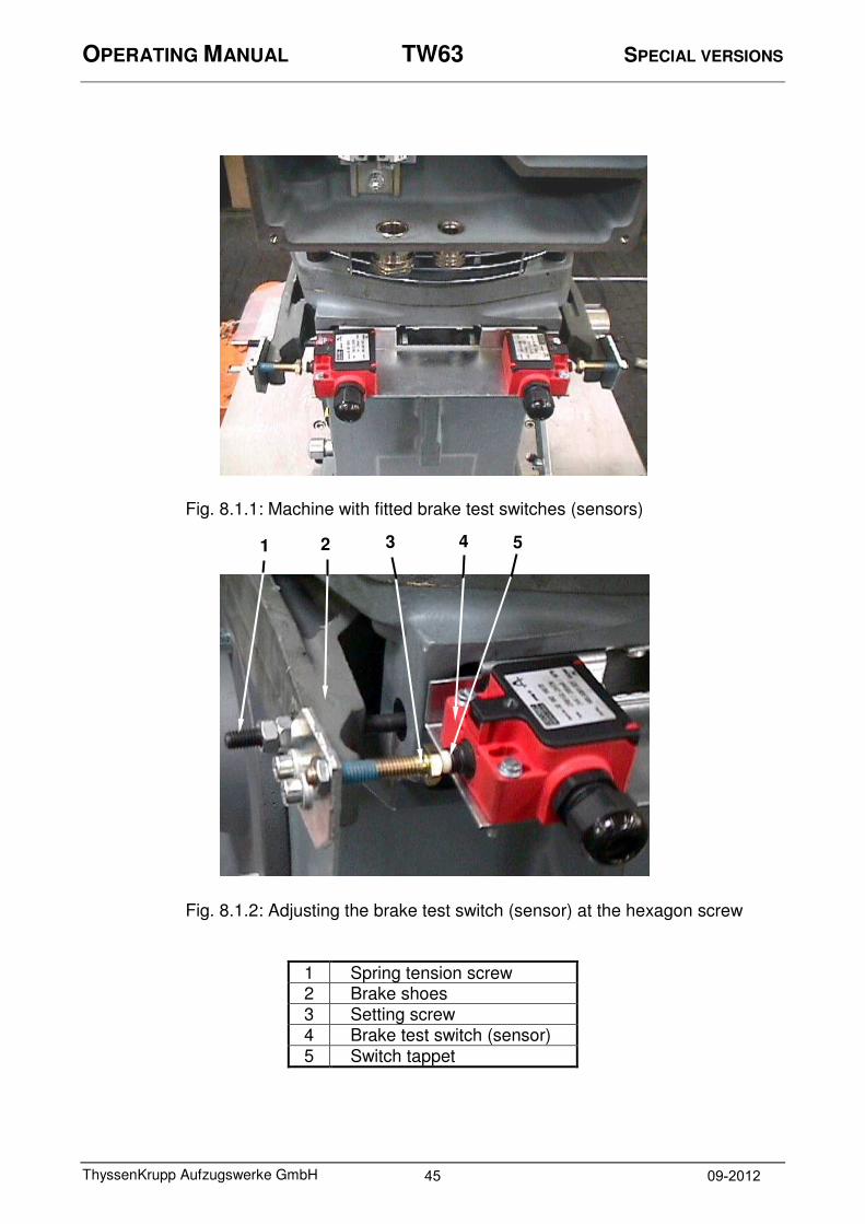
1. If not included in the scope of delivery, make two cables (0.3*0.75 mm² with PVC jacket) for direct connection of the sensors to the control system and connect them.
2. The hexagon screws (microencapsulated) with lock nut that are to be adjusted are pre-assembled on the brake blocks at the plant . The switch tappet on the sensor must be opposite the setting screw, but should not make contact with it.
Setting:
Before starting to set the sensor; the stroke of the brake blocks must be adjusted! For description, see chapter 7
3. Switch on the emergency operation switch and elevator control system.
4. Adjust the setting screw for the switch until the LED lights up.
5. Slowly turn the screw back until the LED goes out.
6. Adjust the setting screw by ¼ revolution (corresponds to around 0.3 mm) towards the switch and tighten the nut.
LED lights up continuously.
7. Activate the motor to open and close the brakes, checking as you do so that there is a switch change at the sensors between opened and closed brake.
Sensor 1 Sensor 2
black B2
brown 24V
black B1
blue 0 V
blue 0 V brown 24V
44 09-2012
OPERATING MANUAL TW63 SPECIAL VERSIONS
ThyssenKrupp Aufzugswerke GmbH
Fig. 8.1.1: Machine with fitted brake test switches (sensors)
Fig. 8.1.2: Adjusting the brake test switch (sensor) at the hexagon screw
1 Spring tension screw 2 Brake shoes 3 Setting screw 4 Brake test switch (sensor)
5 Switch tappet
1 2 3 4 5
45 09-2012
OPERATING MANUAL TW63 APPENDIX
ThyssenKrupp Aufzugswerke GmbH
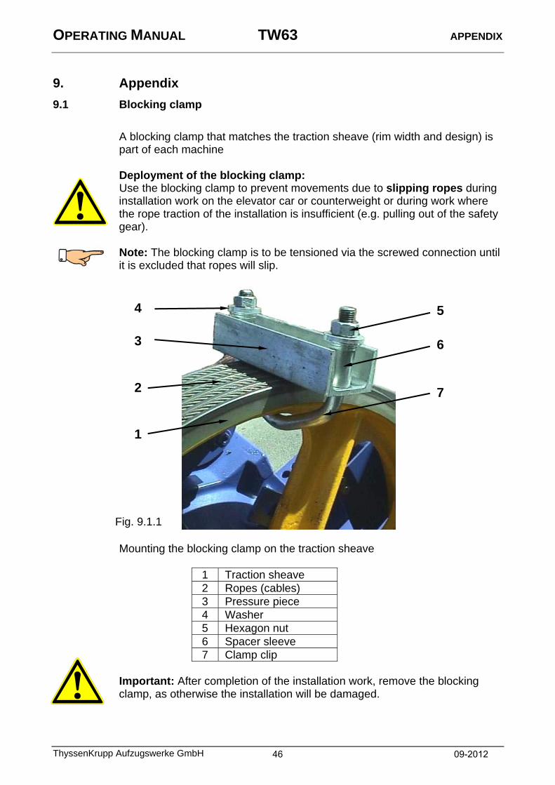
9. Appendix 9.1 Blocking clamp
A blocking clamp that matches the traction sheave (rim width and design) is part of each machine
Deployment of the blocking clamp: Use the blocking clamp to prevent movements due to slipping ropes during installation work on the elevator car or counterweight or during work where the rope traction of the installation is insufficient (e.g. pulling out of the safety gear). Note: The blocking clamp is to be tensioned via the screwed connection until it is excluded that ropes will slip.
Mounting the blocking clamp on the traction sheave
1 Traction sheave 2 Ropes (cables) 3 Pressure piece 4 Washer 5 Hexagon nut 6 Spacer sleeve 7 Clamp clip
Important: After completion of the installation work, remove the blocking clamp, as otherwise the installation will be damaged.
5
6
7 2
3
4
1
Fig. 9.1.1
46 09-2012
OPERATING MANUAL TW63 APPENDIX
ThyssenKrupp Aufzugswerke GmbH
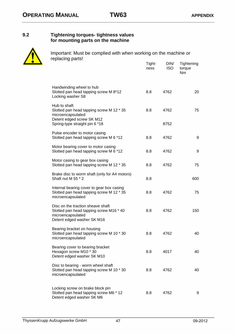
9.2 Tightening torques- tightness values for mounting parts on the machine
Important: Must be complied with when working on the machine or replacing parts!
Tight-ness
DIN/ ISO
Tightening torque Nm
Handwinding wheel to hub Slotted pan head tapping screw M 8*12 8.8 4762 20 Locking washer S8
Hub to shaft Slotted pan head tapping screw M 12 * 35
microencapsulated 8.8 4762 75
Detent edged screw SK M12 Spring-type straight pin 6 *18
8752
Pulse encoder to motor casing Slotted pan head tapping screw M 6 *12
8.8 4762 9
Motor bearing cover to motor casing Slotted pan head tapping screw M 6 *12
8.8 4762 9
Motor casing to gear box casing Slotted pan head tapping screw M 12 * 35
8.8 4762 75
Brake disc to worm shaft (only for A4 motors) Shaft nut M 55 * 2
8.8 600
Internal bearing cover to gear box casing Slotted pan head tapping screw M 12 * 35
microencapsulated
8.8 4762 75
Disc on the traction sheave shaft Slotted pan head tapping screw M16 * 40
microencapsulated 8.8 4762 150
Detent edged washer SK M16
Bearing bracket on housing Slotted pan head tapping screw M 10 * 30
microencapsulated
8.8 4762 40
Bearing cover to bearing bracket Hexagon screw M10 * 30 8.8 4017 40 Detent edged washer SK M10
Disc to bearing - worm wheel shaft Slotted pan head tapping screw M 10 * 30
microencapsulated
8.8 4762 40
Locking screw on brake block pin Slotted pan head tapping screw M6 * 12 8.8 4762 9 Detent edged washer SK M6
47 09-2012

OPERATING MANUAL TW63 APPENDIX
ThyssenKrupp Aufzugswerke GmbH
Tight-ness
DIN/ ISO
Tightening torque Nm
Brake magnet to housing Hexagon screw M16 * 120
8.8 4014 150
Machine to machine base frame (version 1 - 3 / 4) Hexagon screw M20 * 90
Disc 21 Hexagon nut M20 Lock nut M20
8.8 8
4014 125 4032 7967
190 / 350
Tightening torques for mounting parts on the machine base frame Hexagon screw M 6 * 20 8.8 4017 9 Hexagon screw M10 * 16 8.8 4017 40 Hexagon screw M12 * 35 8.8 4017 75 Hexagon screw M16 * 25 8.8 4017 190 Hexagon screw M16 * 40 8.8 4017 190 Hexagon screw M16 * 80 8.8 4017 190 Detent edged washer SK M10 Detent edged washer SK M12 Detent edged washer SK M16 Note:
Fit the screws, washers and detent edged washers, nuts and lock nuts according to thedetails in the drawing enclosed with the base frame and tighten with the specified torqu
48 09-2012

OPERATING MANUAL TW63 APPENDIX
ThyssenKrupp Aufzugswerke GmbH
For use cases not listed in the table, the following apply for Allen screws DIN 912 ISO 4762 Hexagon screws DIN 931 / 933 ISO 4014 / 4017
Dimensions Tightening torque MA (Nm) Tightness 8.8 10.9 12.9 M4 2.6
M5 5.3
M6 9.0 12 15
M8 23 30 35
M10 45 60 75
M12 75 110 130
M16 190 270 320
M20 370 520 620
M24 640 900 1100 The screws are to be tightened with a torque wrench!
Note: Microencapsulated screws are to be replaced after they have been used once.
For assembly, use only original construction and mounting parts from ThyssenKrupp Aufzugswerke GmbH, as otherwise no warranty can be provided.
49 09-2012

OPERATING MANUAL TW63 CHANGES
ThyssenKrupp Aufzugswerke GmbH
10. Changes
Version
Changes
Chapter
09/2012 Table for traction sheave changed (D520 traction sheave), as well as dimensions of the drive (details regarding oil drain at side) added.
2
3
50 09-2012

.
Design for TW63


.
ThyssenKrupp Aufzugswerke GmbH

.
ThyssenKrupp Aufzugswerke GmbH

.
ThyssenKrupp Aufzugswerke GmbH

.
ThyssenKrupp Aufzugswerke GmbH

.
ThyssenKrupp Aufzugswerke GmbH

ABV, ESV and the shaft calculations can be found in the following operating manual: Document number DE 65 999 01 86 0 EN 65 999 02 86 0 FR 9710 000 9229
ThyssenKrupp Aufzugswerke
Operating Manual Emergency Brake System NBS for: TW45C, TW63; TW130; TW160


ThyssenKrupp Aufzugswerke GmbH
Bernhäuser Straße 45
73765 Neuhausen a. d. F.
Germany
e-Mail: [email protected]
Internet: www.thyssenkrupp-elevator-eli.de
Ve
rsio
n 0
9/2
012
Nr.
6
2 3
20
02
86
0