Embed Size (px)
Citation preview
3/26/2014 standards
http://www.aperc.gov.in/Guidelines/Transmission_Standards.html 1/20
TRANSMISSION PLANNING AND SECURITY STANDARDS, POWER SUPPLY PLANNING ANDSECURITY STANDARDS, TRANSMISSION OPERATING STANDARDS AND POWER SUPPLY
OPERATING STANDARDS – 2003
SECTION – I
GENERAL
1. INTRODUCTION
These standards have been framed with reference to Paragraph 17 of the AP Transmission and Bulk Supply Licence.
2. APPLICATION
2.1 The Licensee shall plan and operate its Transmission System and shall plan procurement of electricity and make thesame available to Distribution Licensees and EHT consumers and Generators in conformity with the standards framedhereunder.
2.2 These standards apply to APTRANSCO as Licensee. The Licensee plans and operates the Transmission System withthe standards as the criteria. However, for maintaining the Transmission Standards it is essential for all entities whosesystems are connected to the Transmission system to maintain certain standards and follow certain procedures in theirown systems. It is to be made obligatory that the Generators and DISCOMs to follow such procedures and maintain suchstandards by incorporating suitable provisions in the Grid Code, Power Purchase Agreements and Conditions of Supply andConnection Agreement. Therefore while these standards apply primarily and directly to the Licensee(APTRANSCO) thecorresponding standards apply, although indirectly, to the Generators, DISCOMs and to all either entities whose systemsare connected to the APTRANSCO’s system.
Not withstanding anything contained in these standards the Licensee shall not infringe or violate any of the provisions of
the Indian Electricity Rules 1956.
3. DEFINITIONS
In these standards, unless the context otherwise requires
i) “Act” means the AP Electricity Reform Act, 1998.
ii) “APERC/Commission” means AP Electricity Regulatory Commission constituted under sub-section (1) of
Section 3 of AP Electricity Reform Act, 1998.
iii) “APTRANSCO” means Transmission Corporation of Andhra Pradesh Limited
iv) “CBIP” means Central Board of Irrigation and Power.
v) “CEA” means Central Electricity Authority.
vi) “EHT” means Extra High Tension.
3/26/2014 standards
http://www.aperc.gov.in/Guidelines/Transmission_Standards.html 2/20
vii) “Generator” means an organisation that generates electricity and who is subject to the Grid Code.
viii) “Grid Code” means the code prepared by the Licensee in accordance with the terms of Condition 18 of the
Transmission and Bulk Supply Licence, 2000 and approved by the Commission.
ix) “Grid Code Review Panel/Panel” means a panel set up under Grid Code.
x) “H.T” means High Tension.
xi) “Licensee” means the holder of the AP Transmission and Bulk Supply Licence, 2000.
xii) “PGCIL” means Power Grid Corporation of India Ltd.
xiii) “Rules” means the Indian Electricity Rules,
xiv) “SREB” means Southern Regional Electricity Board.
xv) “SRLDC” means Southern Regional Load Despatch Centre.
xvi) SLDC” means State Load Despatch Centre at Hyderabad.
SECTION – 2
TRANSMISSION PLANNING AND SECURITY STANDARDS
OBJECTIVE
Transmission System planning shall be aimed at the system being capable of delivering power from the generating plantsand interconnecting points with the systems of neighbouring States, and PGCIL to the load centres i.e., the outgoingterminals of the E.H.T. grid sub-stations, under established criteria, while operating the power system as an integratedwhole.
TRANSMISSION PLANNING
Long Term Transmission Planning shall be originated from Load Forecast and Least Cost Generation Expansion Plan of theLicensee for the period under consideration. Since, the Licensee’s system operates in synchronism with generators andcaptive power plants inside the State and SREB system all these elements shall be included in the system modelling. Anyinterconnection existing with the neighbouring State in radial mode shall not be included in the modelling.
2.2 System Modeling
Separate system models shall be developed for each year of a Plan period to assess necessary year of commissioning of
3/26/2014 standards
http://www.aperc.gov.in/Guidelines/Transmission_Standards.html 3/20
particular lines, based on the network, obtaining for the year in question, with the generation and load buses properlylocated.
For modeling purposes, the interconnections with SREB at 400 KV and 220 KV voltage levels and HVDC interconnectionwith EREB & WREB shall be considered. An appropriate electrical equivalent shall be used to take into account the faultlevel at those interconnection points. Since those Buses will be represented as Generator Buses, generation and respectiveloads connected at these Buses shall be included in the modelling. Interconnection with the Eastern Regional Grid and theWestern Regional Grid shall be modelled as they exist.
The HVDC terminals could operate both as rectifiers and inverters. HVDC terminal in the rectifier mode should berepresented as a load and in the inverter mode, it is should be represented as generator. This aspect also is to be takeninto consideration.
System Studies
The system shall be evolved based on detailed power system studies
which shall include but not confined to;
i) Load Flow Studies
ii) Short Circuit Studies
iii) Transient Stability Studies
iv) Loss of load probability studies (LOLP)
Computer Programs
The studies shall be carried out by suitable computer aided programmes.
2.3.3 System Data
The Licensee shall use updated system data, referred to in Transmission Operating Standards, in carrying out systemstudies.
2.3.4 Active and Reactive Load allocation
2.3.4.1 All loads shall be modelled at 220 KV or 132 KV Buses. The load for each Load Bus is obtained for any
year within Plan period from the Load Forecast and a reasonable estimate of transmission losses shall be made to arrive atpeak generation. Procedure adopted for determining the compounded annual growth rate and base year in case of thepeak demand of horizon year can be adopted for deriving the minimum demand of the horizon year.
2.3.4.2 MVAR loading at each Bus shall truly reflect the actual MVAR drawn from the system at that particularlocation by installing / calibrating suitable measuring instruments. The average power shall be computed by studying thepattern by installing suitable meters temporarily or any other acceptable method.
2.4 Load and generation Despatches
2.4.1 Load Studies shall be carried out for Peak Load and Minimum Load conditions.
2.4.2 Generation
For peak load conditions two generator despatches shall be used i.e., Maximum Hydro Generation and Maximum ThermalGeneration. For the minimum load the ‘must-run’ generation shall be used in conjunction with the most economical thermalgeneration. The generation despatch for purpose of carrying out sensitivity studies corresponding to complete closure of agenerating station close to a major load centre shall be worked out by increasing generation at other stations to the extentpossible keeping in view the maximum likely availability at those stations, cost of power etc. Transmission constraints willbe brought out and addressed.
3/26/2014 standards
http://www.aperc.gov.in/Guidelines/Transmission_Standards.html 4/20
2.4.3 Studies shall be repeated for Normal and Contingency conditions as specified under security standards prescribed inthe A.P. Grid Code and the Indian Electricity Grid Code.
2.5 Planning Criteria
2.5.1 The Central Electricity Authority (CEA) “Manual on Transmission Planning Criteria” shall be adopted with modificationas stated below, particularly with reference to steady state voltage limits and security standards for withstanding outages.
2.5.2 Line Loading Limits
The permissible line loading limits shall conform to CEA’s “Manual on Transmission Planning Criteria”. The over loading andunder loading of lines shall be decided accordingly.
2.5.3 Options for Strengthening of Transmission Network
i) Addition of new Transmission lines to avoid over loading of existing system (wherever three or morecircuits of the same voltage class are envisaged between two sub-stations, the next highertransmission voltage may be considered).
ii) Upgradation of the existing transmission lines such as raising height of conductor supports and orswitch over to insulated cross-arms to facilitate change over to higher voltage, if the tower designsso permits.
iii) Reconductoring of the existing transmission line with higher size of conductors or with AAAC (AllAluminium Alloy Conductor)
The choice shall be based on cost, reliability, right of way requirements, energy losses, down time, etc.
2.5.4 All single circuit lines shall be planned with double circuit towers, wherever technically feasible, toenable future expansion without right of way problems.
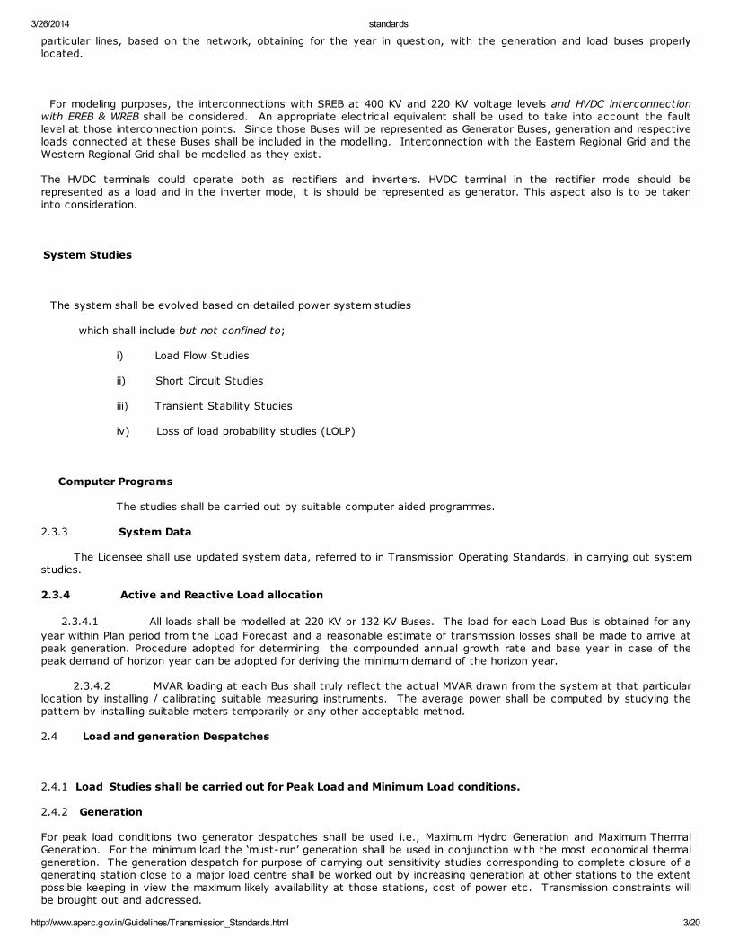
2.5.5 Steady State Voltage Limits
The Licensee shall plan its Transmission System so as to maintain the steady voltage within the limits stated below.
Nominal Voltage Maximum Minimum(KV)
420
245
145
360
200
120
400
220
132
SECURITY STANDARDS
3.1 Steady State Stability
The system shall be planned to supply loads during normal conditions and the following contingency conditions without theneed for rescheduling of generation and to maintain voltage and line loading criteria.
Outage of one transmission circuit
Outage of one Interconnecting Transformer or
Outage of one generator.
Outage of a 400 KV DC (Double Circuit AC) line in case of evacuation for a generating station of 1000 MW and abovelocated in a difficult terrain like sea coast susceptible to yearly cyclones(as per clause 6 of CEA’s manual on TransmissionPlanning).
3/26/2014 standards
http://www.aperc.gov.in/Guidelines/Transmission_Standards.html 5/20
(Prior to such contingency, all elements shall be considered to be in service.
After5 years for adopting CEA/IEGC norms: “ One circuit being already out of service in another corridor” will be adopted).
3.2 Transient Stability
3.2.1 The system shall be designed to maintain synchronism and system integrity (i.e. a condition wherein allgenerating units continuously operate in synchronism without tripping and getting separated) under the followingdisturbances:
a) The outage of the single largest unit in the SREB system. (For this condition the APTRANSCO share ofspinning reserve shall be considered as 285 MW being 38 % of one 750 MW unit).(as per load generationbalance report of SREB). However this is subject to review on change of system conditions.
b) A permanent single line to ground (SLG) fault on a 400 KV transmission circuit, single pole opening of thefaulted phase (100 m.sec or 5 cycles) with unsuccessful reclosure (dead time 1 sec.) followed by 3 poleopening (100 m.sec) of the faulted line on a 400 KV transmission circuit (subject to note below).
Note:- In order to facilitate simulation, a 3 phase fault with 5 cycle duration shall be considered for 400 KV circuitfault. Should the system survive this fault condition, it shall be assumed that system’s stability isestablished. Should the simulation not indicate stability, then the single phase shall be simulated and SLGFAULT CRITERIA shall be applied.
c) A permanent three phase fault with a duration of 160 m.sec (8 cycles) on a 220 KV or 132 KV Transmissioncircuit assuming 3-pole opening.
d) No stability studies shall be made for radial lines.
4. SUBSTATION PLANNING CRITERIA
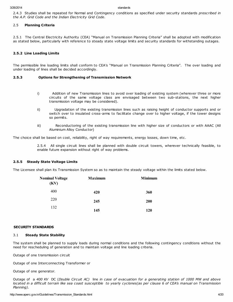
The rated rupturing capacity of the Circuit Breaker in any sub-station shall not be less than 125% of the maximum faultlevel at that sub-station. (The 25% margin is intended to take care of the increase in short circuit levels as the systemgrows). The standard rated breaking current capacity of switch gear at different voltage levels are as follows:
Voltage Level Breaking Current (KA) 132 KV 31.5 KA
220 KV 40 KA
400 KV 40 KA
4.2 The capacity at any single sub-station at different voltage levels shall not normally exceed.
Voltage Level Capacity
400 KV 1000 MVA
220 KV 320 MVA
132 KV 150 MVA
Size and number of Interconnecting Transformers (ICT’s) shall be planned in such a way that the outage of any single unitwould not normally over load the remaining Interconnecting transformers. Size and number of EHT/H.T transformers shall beplanned in such a way that in the event of outage of any single unit the remaining EHT/H.T Transformers would still supply80% of the load.
4.4 Further, Local Breaker Backup (LBB) protection is to be provided for all 220 KV and 400 KV feeders.
4.5 Reactive Power Compensation
4.5.1 Shunt Capacitors
Reactive compensation shall be provided as far as possible in 132 KV systems with a view to meet the reactive powerrequirement of load close to the load points. In the planning study the shunt capacitors required shall be shown at 132/220KV Buses.
3/26/2014 standards
http://www.aperc.gov.in/Guidelines/Transmission_Standards.html 6/20
4.5.2 Shunt Reactors
Switchable shunt reactors shall be provided at 400 KV sub-stations for controlling voltages within the limits specified. Thestep changes shall not cause a voltage variation exceeding 5%. Suitable Line Reactors (Switchable/Fixed) shall be providedto enable charging of 400 KV lines without exceeding voltage limits specified.
SECTION – 3
POWER SUPPLY PLANNING AND SECURITY STANDARDS
OBJECTIVE
Power Supply Planning is to aim at a least cost planning to serve the demand at a specified level of reliability.
2. POWER SUPPLY PLANNING
Long term power supply planning shall be made based on Load Forecasts prepared pursuant to condition 17.12 of the APTransmission and Bulk Supply Licence. The Licensee shall abide by conditions of GRIDCODE in formulating its long term loadforecasts. The planning process shall take into account the existing contracted generation capacity, allocation fromCentral Sector Generation in the base year and evolve the net additional requirement of power over the years during theplan period. The planning process shall also consider an extended study period of ten years beyond the base period of tenyears to smoothen out the “End Effects” due to different types of generation capacity at the end of the base period. Whileevolving the planning process the capacity addition programmed shall be at the Strategic locations in the Grid subject tosystem requirement and constraints like fuel availability, load center and evacuation facilities.
PLANNING CRITERIA
3.1 Peaking Availability
The peaking availability of existing Hydro Electricity Plants and thermal Plants/Private/Joint Venture plants shall be inaccordance with data furnished by the respective Generating Companies and also as per Power Purchase Agreements madewith respective power stations. Availability from Central Sector Plants shall be taken as allocated by the Government ofIndia. For the new plants, peak availability shall be as per Central Electricity Authority norms.
3.2 Plant Availability
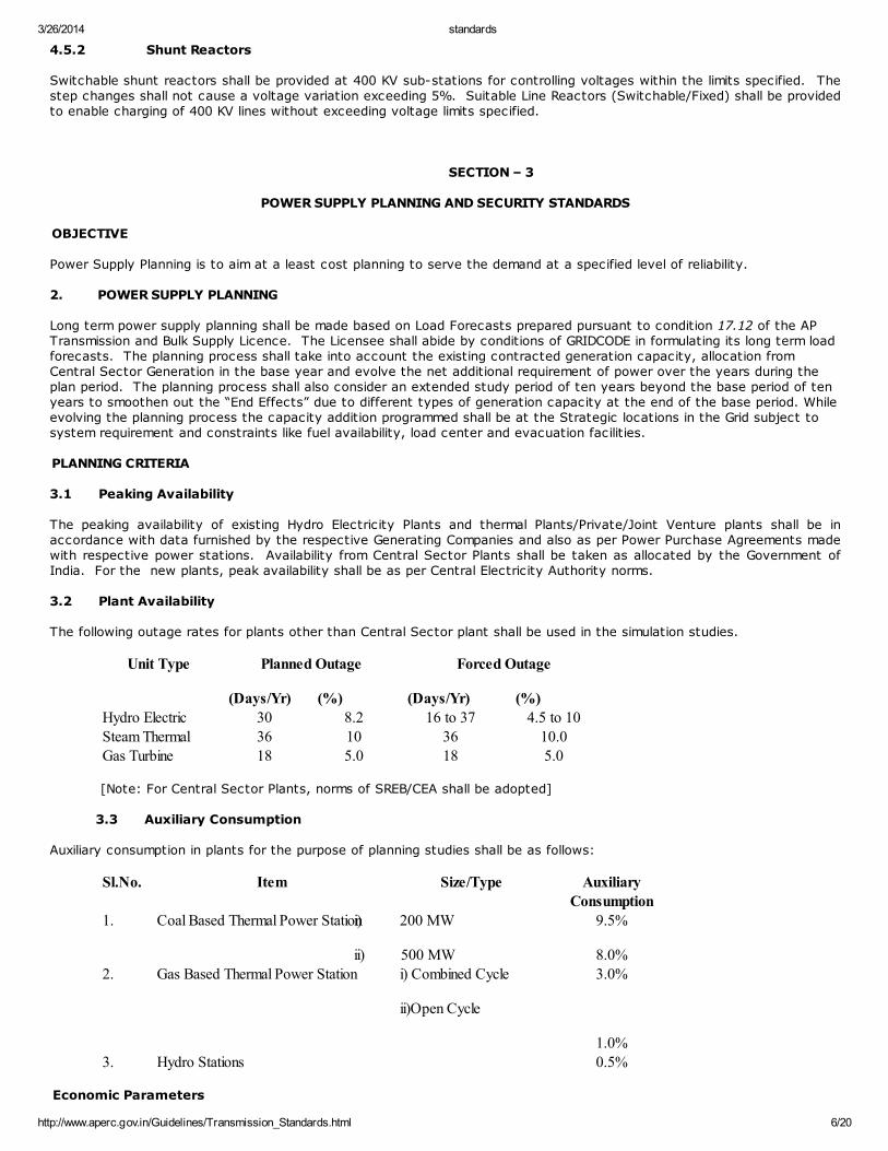
The following outage rates for plants other than Central Sector plant shall be used in the simulation studies.
Unit Type Planned Outage
(Days/Yr) (%)
Forced Outage
(Days/Yr) (%)
Hydro Electric 30 8.2 16 to 37 4.5 to 10Steam Thermal 36 10 36 10.0Gas Turbine 18 5.0 18 5.0
[Note: For Central Sector Plants, norms of SREB/CEA shall be adopted]
3.3 Auxiliary Consumption
Auxiliary consumption in plants for the purpose of planning studies shall be as follows:
Sl.No. Item Size/Type AuxiliaryConsumption
1. Coal Based Thermal Power Stationi) 200 MW
ii) 500 MW
9.5%
8.0%2. Gas Based Thermal Power Station i) Combined Cycle
ii)Open Cycle
3.0%
1.0%3. Hydro Stations 0.5%
Economic Parameters
3/26/2014 standards
http://www.aperc.gov.in/Guidelines/Transmission_Standards.html 7/20
3.4.1 Reference Year for Costs
The cost estimate shall reflect economic conditions as on 1st April of the Base Year. The cost shall increaseover time at the rate of general inflation and shall exclude taxes and duties in so far as they are common inthe economic evaluation.
3.4.2. Reference Year for Present Value Analysis
Discounting for calculating cumulative present value cost for each scheme shall be done at an annual rate of10%.
3.4.3. Plant Economic Life
The economic life of Generating plants may be assumed as follows for the planning studies in accordance with Govt. ofIndia notification dt.27.3.1994 made under sub paragraph (a) of Paragraph VI of the VI schedule to the Electricity (Supply)Act, 1948, from time to time.
Plant Type Life (Years)
Hydro Electric 35
Thermal 25
Gas Turbine 15
3.4.4 Cost of Unserved Energy
Value of unserved energy (i.e. the loss to the economy if a KWH of energy required by consumers cannot be supplied) shallbe considered in the economic analysis for the least cost generation expansion plan. Suitable pricing for such poweroutage costs shall be adopted from available studies applicable to AP.
3.5 Evaluation of Planning Studies
3.5.1 Suitable computer aided programmes shall be adopted to arrive at a least cost generation expansion plan.
3.5.2 The economic evaluation shall be carried out in accordance with the guidelines enumerated below:
i) Set out different generation expansion scenario incorporating mixed hydro/thermal expansion, onlythermal expansion, mixed base/peak generation expansion, in the context of demand forecast.
ii) For each scenario, determine through simulation, the timing of new installations during the planningperiod in order to meet the security standards.
iii) Simulate the system operation in order to obtain the average annual energy production from eachhydro electric plant and each thermal plant.
iv) Compute the cumulative present value cost for the scenario over the planning period incorporatingcapital costs for new generation and associated transmission, fixed and variable operation andmaintenance costs, fuel costs and unserved energy costs.
v) Compare the present value cost of each scenario with that of the other to arrive at the least costscenario.
vi) Calculate the Long Run Marginal Cost for the least cost scenario as follows:
(a) For each year of the plan period determine incremental cost of generation, energyrequirement, energy generated, unserved energy, incremental net energy generated, loss ofload probability in hours, Unserved Energy %
(b) Reduce the incremental cost of generation to the Net Present Value.
(c) Long Run marginal cost in Rs./KWH is:
Total net present value of incremental cost of generation (Rs.)
= ---------------------------------------------------------------------------
3/26/2014 standards
http://www.aperc.gov.in/Guidelines/Transmission_Standards.html 8/20
Incremental net energy generation (KWH)
4. POWER SUPPLY SECURITY STANDARDS
To ensure that the generation reserve is sufficient so that the system can meet the load, even if one or more units are outof service for scheduled maintenance or in the event of non-availability of adequate hydro-electric generation capacityduring the dry period, adequate reserve capacity shall be built into the system both for capacity and energy.
4.1 Capacity Reserve Criteria.
Loss of Load Probability (LOLP) of 1% and 0.15% unreserved energy as per CEA standards shall be used for planningmodels. This shall mean that for 1% of the year (i.e. upto 3.65 days/year) the power system may experience shortages ofgenerating capacity.
4.2 A contingency reserve margin equal to 5% of the system peak load shall be planned to take care of fluctuations inthe availability of Hydro Electric generation during the critical period of February to June of a dry-year, and to account foroutages of units, power station equipment, non-availability of Central Sector share in order to maintain security andintegrity of the system.
4.3 Energy Reserve Criteria.
“Energy Not reserved” shall be limited to 0.15% of the average annual energy.
SECTION – 4
TRANSMISSION OPERATING STANDARDS
OBJECTIVE
These standards shall serve as guidelines for the Licensee to operate its Transmission System for providing an efficient,coordinated and economical system of electricity transmission.
2. DATA MANAGEMENT
2.1 The Licensee shall acquire, store and manage following data relating to its Transmission System and generatingUnits of Generators.
i) Line data
ii) Transformer data including Generation Transformers
iii) Bus data including that of Generating Stations
iv) Generator data (inclusive of Captive Power Plant)
v) Demand data for each EHT sub-station
vi) Real Time Data
vii) Schedule maintenance plan of generating units.
2.2 Details of data shall be as specified in Annexure – 1.
3. LOAD DESPATCH
3.1 The Licensee shall establish a State Load Despatch Centre and run it round the clock for the purposes of
i) Daily Generation Scheduling and issuing despatch instructions.
ii) Monitoring line MW and MVAR drawals, EHT Bus voltages, Frequency.
iii) Monitoring Generation out-put.
iv) Coordinating restoration process after total or partial blackouts in the Transmission System or RegionalSystem.
3/26/2014 standards
http://www.aperc.gov.in/Guidelines/Transmission_Standards.html 9/20
COMMUNICATION
4.1 The Licensee shall establish reliable and efficient point to point voice and data communication links between SLDC,SRLDC, Generating Stations and EHT sub-stations.
4.2 All operational communications/instructions transmitted by SLDC or transmitted to SLDC shall be recorded asevidence of the communications/instructions.
5. OUTAGE PLANNING
5.1 The Licensee shall ensure that its plan for outage of circuits/Transformers required for maintenance, construction,modification, diversion etc. does not violate the security standards of transmission system.
a) following loss of the largest in-feed, and
b) for the loss of Transmission elements such as a single circuit, a cable, an ICT or a DC line, there shall be
i) no loss of supply and
ii) no part of the transmission system operating out of synchronism (note that these are probably thesame as the Planning Standards but may be relaxed, depending on actual circumstances prevailing atthe time).
6. SYSTEM STUDIES
6.1 The Licensee shall carry out system studies including Load flow, short circuit and Transient stability studies as oftenas required but at least once in a year.
6.2 The Licensee shall endeavour for optimal use of existing reactive resources and the reactive reserves in the systemto meet the steady state voltage limits at all Buses in the Transmission System as set in “Planning and Security Standardsfor Transmission System”.
6.3 The Licensee shall coordinate the settings of the Relays in the Protection Schemes of its Transmission system withthose of the Generators, PGCIL and grid system of neighbouring States at respective points of interconnections.
6.4 As a routine measure, the Licensee shall intimate all users of the Transmission System, the approximate fault level ofthe Transmission system at each point of interconnection both at EHT Bus and at H.T. Bus.
6.5 The Licensee shall prepare schedule of operation of on-load Taps of load-transformers and interconnectingtransformers at each EHT sub-station in the Transmission System under different Generation and load despatches asstipulated in the system studies and enforce its implementation under similar situations obtained in practice.
7. DEMAND MANAGEMENT
7.1 The Licensee shall monitor MW/MVAR loading of each EHT line and each interconnecting transformer on real timebasis at SLDC. Similarly, the loadings on each load transformers at EHT sub-station shall be closely monitored during peakload hours.
7.2 If any system component is being over loaded/over heated, the load on the same shall be reduced by followingsuitable procedure.
8. VOLTAGE MANAGEMENT
8.1 The Licensee shall monitor voltage levels at all EHT sub-stations of its Transmission System on real time basis atSLDC.
8.2 Since voltage is affected both by frequency and reactive power flow, system
voltage shall be regulated by taking all possible measures to regulate system frequency and reactive power flows.
8.3 All local voltage problems shall be addressed by attending to local transformer taps.
8.4 In case of system High Voltage, Licensee shall take following measures:
i) Generator plant to increase MVAR absorption subject to stability limit.
ii) Switch off capacitors.
iii) Switch in bus reactor where provided.
3/26/2014 standards
http://www.aperc.gov.in/Guidelines/Transmission_Standards.html 10/20
iv) Switch off one circuit lightly loaded.
v) Reduce transformer taps .
vi) Address high frequency problem.
vii) Transformer taps.
8.5 In case of system low voltage, Licensee shall take following measures:
i) Restoration of circuits under outage.
ii) Switch out the reactors where provided.
iii) Switch on capacitors.
iv) Generator plant to increase MVAR generation.
v) Increase the transformer taps.
vi) Demand reduction.
vii) Address low frequency problem.
9. AUTOMATIC UNDER FREQUENCY LOAD SHEDDING
9.1 The Licensee in consultation with users of Transmission system shall identify H.T Feeders emanating from EHT sub-stations to drop automatically and sequentially loads in blocks when the system frequency begins falling from 49 Hz.Quantum of loads to be shed in blocks from EHT sub-stations at each of the following stages of under frequency shall bedetermined.
Stage I : 49.0 Hz
Stage II : 48.8 Hz
Stage III : 48.6 Hz
10. ISLANDING SCHEME
10.1 To avoid total black out of the grid, during system disturbance and for early normalisation, an islanding schemeinvolving major generating stations and part/parts of Transmission System shall be developed in consultation with SRLDC.
11. SAFETY COORDINATION
11.1 The Licensee shall observe the General Safety Requirements as laid down in I.E.Rules for construction, installation,protection, operation and maintenance of electric supply lines and apparatus.
11.2 The Licensee shall designate suitable control persons as specified in GRID CODE for coordination of safetyprocedures before work is taken up, during work, and after work is completed till the concerned system component isenergised both inside its own Transmission System and across between Licensee’s Transmission System and that of anyUser.
11.3 The Licensee shall develop its own Safety Manual for the purpose of Safety Coordination.
12. EVENT REPORTING
12.1 The Licensee shall monitor all abnormal occurance or events affecting the operation of system requiring attention,outlined in GRID CODE.
12.2 The Licensee shall ensure that within ten minutes of an occurrence, verbal/telephonic communication shall be madeto a designated officer by SE/Grid Operation who shall be in position and authority to initiate follow up action as deemedfit. The SE/Grid Operation must, however, give utmost priority in safeguarding the system before initiating the reportingprocedure.
12.3 Within 30 minutes, a preliminary report shall be prepared in a Form to be standardised by Licensee and communicateto the designated officer/officers.
12.4 Within 48 hours, detailed report shall be prepared in a Form to be standardised by Licensee and communicated tothe designated officer/officers.
3/26/2014 standards
http://www.aperc.gov.in/Guidelines/Transmission_Standards.html 11/20
12.5 The name and designation of the officer shall be furnished to all stake holders for the communication of event data.
12.6 The generator shall give the computerized data to SLDC/RLDC whenever any event occurs affecting the systemstability.
12.7 APTRANSCO should plan to provide event loggers to all existing important 220 KV substations and to all new 220 KVsubstations to be set up in future.
13. POST DISTURBANCE ANALYSIS
13.1 All major grid disturbances causing tripping of Generating Units (110 MW and above), tripping of EHT lines (220 KVand above) causing full or partial System Black out, breakdown of Inter connecting Transformers (100 MVA and above),break down of EHT lines causing prolonged interruption and load restrictions shall be immediately discussed and analysed inthe GRID CODE REVIEW PANEL. This shall promptly be done following discussion and analysis in any Sub-panel that may beformed by the panel for the purpose.
13.2 Disturbance Reports and recommendations made in such meetings shall be compiled and circulated to all members ofGRID CODE REVIEW PANEL for its implementation.
14. MAINTENANCE, STANDARDISATION, SPARES, TESTING AND INSPECTION
14.1 The Licensee shall develop maintenance schedules of lines and sub-station equipment in conformity with I.E. Rulesand relevant CBI & P Manuals.
14.2 The Licensee shall establish a hierarchy for implementation of the maintenance standards and its monitoring.
14.3 No EHT line shall suffer total interruption for more than 175 hours in a year including planned outages but excludingForce Majeure causes.
14.4 No HT supply at points of interconnection shall suffer total interruption for more than 310 hours in a year includingplanned outages and excluding Force Majeur causes.
14.5 For the purposes of reducing inventory, procurement time, installation time, the Licensee shall adopt standardiseddesigns for Transmission Line Towers, Structures for sub-stations, standardise layouts for sub-stations, sub-stationlighting, Control Room lighting and ventilation, sub-station earthing, prepare standard specifications for line materials,transformers, sub-station equipment, Cables, Bus bar accessories, insulators and hardwares, etc.
14.6 For convenience of maintenance, repairs, and replacement of line equipment and sub-station equipment, theLicensee shall develop and observe a policy on spare parts.
14.7 The Licensee shall establish Electrical Testing Laboratories of its own, equipped for Routine Testing of Relays,Meters, Current-Transformers, Potential Transformer, Condenser Bushing and other electrical accessories used in sub-stations in accordance with relevant Indian Standards and Manufacturers’ instructions.
14.8 The Licensee shall establish testing organisations under its control, staffed with qualified, trained and skilledpersons and equipped with all necessary testing equipment, power supply etc. for conducting field tests and Commissioningtests of sub-station equipment such as Transformer, Circuit Breaker, Current Transformer, Potential Transformer, StationBattery, relays and meters, Control Wiring, Cables, Lightning Arrester, sub-station earthing etc.
14.9 The Licensee shall maintain in good order and condition all necessary equipment, tools, tackles etc. for carrying outmaintenance of lines and sub-stations equipment and ensure their availability at all sub-stations.
14.10 The Licensee shall carry out periodical inspection of all lines and sub-stations in its Transmission system, through anindependent inspection team, qualified for the purpose, to ensure that maintenance of lines and sub-stations are carriedout as per maintenance schedules.
SECTION-5
POWER SUPPLY OPERATING STANDARDS
1. OBJECTIVE
These standards set in levels of operational security and quality of supply, which the Licensee shall be obliged to maintainin making power available for the purposes of supply to consumers, as laid down in AP Transmission and Bulk supply Licence,2000.
2. OUTAGE PLANNING
3/26/2014 standards
http://www.aperc.gov.in/Guidelines/Transmission_Standards.html 12/20
2.1 The generation output shall be matched with estimated demand taking into account the Transmission/Generationoutages so as to achieve the Transmission and Power Supply Security Standards. The Licensee shall abide by the relevantprovisions in the GRID CODE to achieve coordination between Transmission outage programmes and Generation outageProgrammes.
3. GENERATION SCHEDULE AND DESPATCH
3.1 The generating scheduling should be strictly based on merit order duly taking into account the following factors:
i) System Demand
ii) Merit Order operation of Generating Units
iii) Availability of Generating Units
iv) Constraints on the Transmission Systems
v) Security Requirements
vi) System Losses
3.2 The Licensee shall accordingly prepare the Generation Schedule and their despatches on hourly day ahead basis, onthe basis of data provided by Generators and CPP’s and in consultation with SRLDC regarding allocated drawal for the dayfrom Central Sector Generating Stations. The day ahead generation schedule shall be communicated to the Generators andSRLDC in the manner out lined in GRIDCODE.
3.3 Total minimum spinning reserves of 5% of System Peak Load shall be achieved by making suitable allocations tospecific generating stations in consultation with SRLDC.
4. FREQUENCY MANAGEMENT
4.1 The Licensee shall endeavour to run the system within a Frequency range of 49.0 to 50.5 Hz as per the norms ofIEGC.
i) Check generation scheduling vs. generation and request concerned Generator with excess generation to conform togeneration schedule.
ii) Advise Hydro Stations to reduce generation without water spillage.
iii) Advise Coal Fired Thermal Stations having 210/500 MW units to back down to ‘X’ multiplied by the load factor(where ‘X’ is the generation of particulars units during peak hours) but not to the extent requiring oil support.
In case Frequency rises to 50.5 Hz inspite of above measures, the Licensee shall:
i) Advise coal fired thermal stations having 210/500 MW units to bring down generation to bare minimum using oilsupport or if necessary to shut off 210 MW sets.
4.2.2 In case the Frequency begins to rise above 50.5 Hz and does not fall below 50.8 Hz, the Licensee shall inconsultation with SRLDC regulate the generation to bring down the frequency to 50 Hz.
4.3 The Licensee shall be vigilant when frequency begins to fall below 49.5 Hz and initiate following measures to raisethe System Frequency to about 50 Hz.
i) Check generation scheduling Vs. generation and request concerned Generator with less generation to conform togeneration schedule.
ii) Check whether there is any excess drawal at any points of interconnection by any Distribution and Retail SupplyLicensee and advise to restrict its drawal within schedule.
iii) Advise Hydro Stations to synchronise stand by machines, if available.
4.3.1 In case the Frequency still falls and reaches 49.0 Hz the Licensee shall advise Distribution Licensees to shed loadmanually in predetermined blocks.
4.3.2. In case the Frequency still continues to fall and reaches 48.5 HZ, the Licensee shall in consultation with SRLDCIsland its system from rest of SREB if there is Export at points of interconnection.
5. STANDARDS TO BE MET BY GENERATORS
3/26/2014 standards
http://www.aperc.gov.in/Guidelines/Transmission_Standards.html 13/20
5.1 Licensee, while contracting Bulk power supply from Generators shall specify, voltage and frequency standards withlimits of variation in the power purchase agreement, which the Generator has to accommodate.
5.2 Licensee shall incorporate conditions in the power purchase Agreement requiring the Generators to commit:-
i) Spinning Reserve Response during Frequency transients at different load levels.
ii) Reactive power capability (MVAR)
iii) Economic back down level
iv) Load increment rate from back down level to maximum continuous Rating (MW/min)
v) Loading decrement rate from maximum continuous rating to back down level (MW/min).
vi) Pick up rates on synchronising in MW under conditions:
a) Cold Start
b) Warm Start
c) Hot Start
vii) That Generator has to comply AP GRID CODE and Indian Electricity Grid Code to the extent that it does notjeopardise safety of its plant and personnel.
6. GENERATION RESERVE
6.1 The Licensee shall plan for necessary capacity and Energy reserves in accordance with Security Standards.
6.2 These reserves shall be allocated to the Generators in the following manner:
Contingency Reserve/Spinning Reserve - 3%
(As system facing shortage of power and energy, the contingency reserve and spinning reserve can be consideredafter the system attains self sufficiency)
MONITORING OF GENERATION
7.1 The Licensee shall provide facilities at SLDC for receiving following real time data from Generators:
i) Frequency
ii) MW output
iii) MVAR output
iv) MW and MVAR flow in outgoing lines
v) Voltage at interconnection Bus (The Licensee should ensure that it has adequate facilities to maintainvoltages at the bulk supply points to within prescribed limits during normal and planned outage conditions. In case such facilities do not exist then the Licensee should provide the same within two to three years).
7.2 The Licensee shall establish procedure for monitoring the following parameters of a generation plant:
i) Declared Gross Generation capacity
ii) Loading rate of a unit
iii) De-loading rate of a unit
iv) Active and Reactive power delivery following Despatch instructions
3/26/2014 standards
http://www.aperc.gov.in/Guidelines/Transmission_Standards.html 14/20
v) Capability of Generating plant to meet Spinning Reserve requirements.
* * *
Annexure-1
Data for Operation and Studies
(With reference to Para 2 of Section-4)
All data should be on 100 MVA base.
1. Line data for al lines of 132 KV level and above
From Bus No. :
From Bus Name :
To Bus No. :
To Bus Name :
Volt. Level (KV) :
Ckts No. :
Line length (KM) :
Conductor size & No. of :
Conductors per phase :
Pos.Seq. Resistance/KM :
(in p.u)
Pos. seq Reactance/KM :
(in p.u.)
Pos. seq half line :
Susceptance/KM
(in p.u.)
Zero seq Resistance/KM :
(in p.u.)
Zero seq Reactance/KM :
(in p.u.)
Zero seq Half Line :
Susceptance/KM
(in p.u.) :
Line capacity (AMPS) :
3/26/2014 standards
http://www.aperc.gov.in/Guidelines/Transmission_Standards.html 15/20
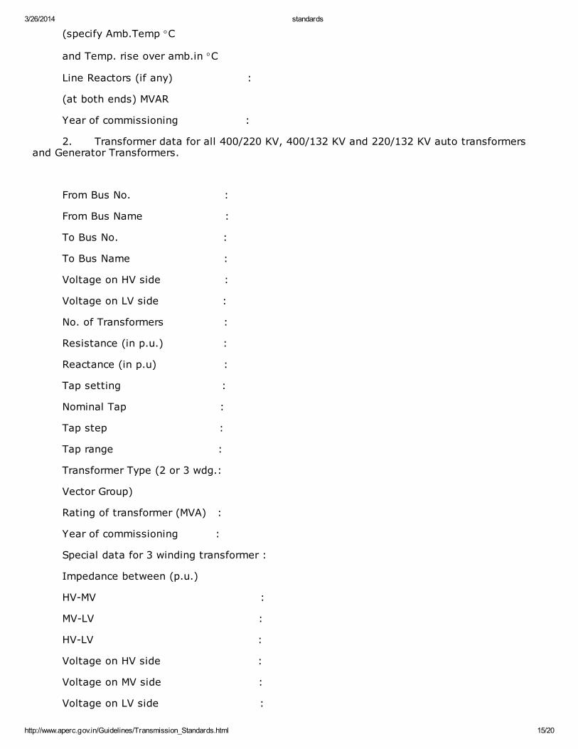
(specify Amb.Temp °C
and Temp. rise over amb.in °C
Line Reactors (if any) :
(at both ends) MVAR
Year of commissioning :
2. Transformer data for all 400/220 KV, 400/132 KV and 220/132 KV auto transformersand Generator Transformers.
From Bus No. :
From Bus Name :
To Bus No. :
To Bus Name :
Voltage on HV side :
Voltage on LV side :
No. of Transformers :
Resistance (in p.u.) :
Reactance (in p.u) :
Tap setting :
Nominal Tap :
Tap step :
Tap range :
Transformer Type (2 or 3 wdg.:
Vector Group)
Rating of transformer (MVA) :
Year of commissioning :
Special data for 3 winding transformer :
Impedance between (p.u.)
HV-MV :
MV-LV :
HV-LV :
Voltage on HV side :
Voltage on MV side :
Voltage on LV side :
3/26/2014 standards
http://www.aperc.gov.in/Guidelines/Transmission_Standards.html 16/20
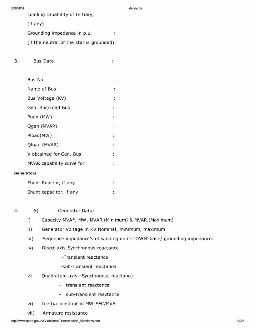
Loading capability of tertiary,
(if any)
Grounding impedance in p.u. :
(if the neutral of the star is grounded):
3. Bus Data :
Bus No. :
Name of Bus :
Bus Voltage (KV) :
Gen. Bus/Load Bus :
Pgen (MW) :
Qgen (MVAR) :
Pload(MW) :
Qload (MVAR) :
V obtained for Gen. Bus :
MVAR capability curve for :
Generators
Shunt Reactor, if any :
Shunt capacitor, if any :
4. A) Generator Data:
i) Capacity-MVA*, MW, MVAR (Minimum) & MVAR (Maximum)
ii) Generator Voltage in KV Nominal, minimum, maximum
iii) Sequence impedance’s of winding on its ‘OWN’ base/ grounding impedance.
iv) Direct axis-Synchronous reactance
-Transient reactance
-sub-transient reactance
v) Quadrature axis –Synchronous reactance
- transient reactance
- sub-transient reactance
vi) Inertia constant in MW-SEC/MVA
vii) Armature resistance
3/26/2014 standards
http://www.aperc.gov.in/Guidelines/Transmission_Standards.html 17/20
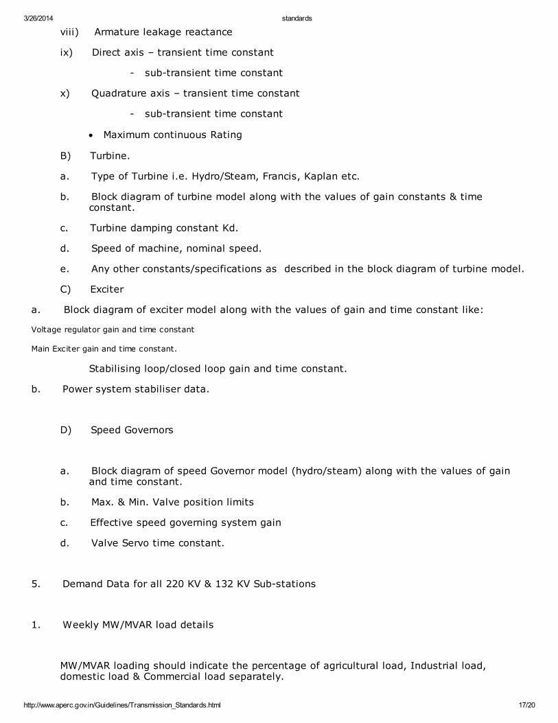
viii) Armature leakage reactance
ix) Direct axis – transient time constant
- sub-transient time constant
x) Quadrature axis – transient time constant
- sub-transient time constant
· Maximum continuous Rating
B) Turbine.
a. Type of Turbine i.e. Hydro/Steam, Francis, Kaplan etc.
b. Block diagram of turbine model along with the values of gain constants & timeconstant.
c. Turbine damping constant Kd.
d. Speed of machine, nominal speed.
e. Any other constants/specifications as described in the block diagram of turbine model.
C) Exciter
a. Block diagram of exciter model along with the values of gain and time constant like:
Voltage regulator gain and time constant
Main Exciter gain and time constant.
Stabilising loop/closed loop gain and time constant.
b. Power system stabiliser data.
D) Speed Governors
a. Block diagram of speed Governor model (hydro/steam) along with the values of gainand time constant.
b. Max. & Min. Valve position limits
c. Effective speed governing system gain
d. Valve Servo time constant.
5. Demand Data for all 220 KV & 132 KV Sub-stations
1. Weekly MW/MVAR load details
MW/MVAR loading should indicate the percentage of agricultural load, Industrial load,domestic load & Commercial load separately.
3/26/2014 standards
http://www.aperc.gov.in/Guidelines/Transmission_Standards.html 18/20
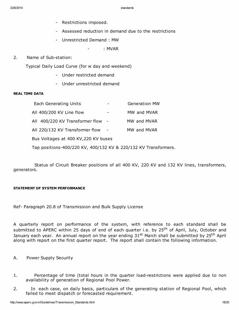
- Restrictions imposed.
- Assessed reduction in demand due to the restrictions
- Unrestricted Demand : MW
- : MVAR
2. Name of Sub-station:
Typical Daily Load Curve (for w day and weekend)
- Under restricted demand
- Under unrestricted demand
REAL TIME DATA
Each Generating Units - Generation MW
All 400/200 KV Line flow - MW and MVAR
All 400/220 KV Transformer flow - MW and MVAR
All 220/132 KV Transformer flow - MW and MVAR
Bus Voltages at 400 KV,220 KV buses
Tap positions-400/220 KV, 400/132 KV & 220/132 KV Transformers.
Status of Circuit Breaker positions of all 400 KV, 220 KV and 132 KV lines, transformers,generators.
STATEMENT OF SYSTEM PERFORMANCE
Ref- Paragraph 20.8 of Transmission and Bulk Supply License
A quarterly report on performance of the system, with reference to each standard shall be
submitted to APERC within 25 days of end of each quarter i.e. by 25th of April, July, October and
January each year. An annual report on the year ending 31st March shall be submitted by 25th Aprilalong with report on the first quarter report. The report shall contain the following information.
A. Power Supply Security
1. Percentage of time (total hours in the quarter load-restrictions were applied due to nonavailability of generation of Regional Pool Power.
2. In each case, on daily basis, particulars of the generating station of Regional Pool, whichfailed to meet dispatch or forecasted requirement.
3/26/2014 standards
http://www.aperc.gov.in/Guidelines/Transmission_Standards.html 19/20
3. In each case, the estimated amount of demand curtailed and areas or consumer categorieswhich were affected.
B. Transmission Security
1 Percentage of time (total hours in the quarter) load restrictions were applied, due to non-availability of transmission capacity, even though generation/Regional pool capacity wasavailable.
2 Percentage of time (total hours in the quarter) generation had to be rescheduled, due to non-availability of transmission capacity, even though load restriction was not required.
3 In each case the transmission element (e.g. line, transformer, circuit breaker etc.) which wasnot available, resulting in loss of transmission capacity. The reason for non availability ofthe transmission element (e.g.scheduled maintenance outage, unscheduled maintenanceoutage, forced outage, with details) shall be furnished.
4 In each case the Grid sub-station affected, the extent of generation rescheduling required,estimated capacity restriction effected, area/consumer categories affected.
C. Overall Performance
1. Frequency
a) Percentage of time (total hours in the quarter), grid frequency was (I) above higher valuepermitted under IE Rules 1956, (ii) below lower value permitted under IE Rule, 1956.
b) The maximum continuos period of deviation, with date and time and reason for suchcontinuous deviation.
c) The highest and lowest grid frequency observed, value, time and date of occurrence. In casethis was accompanied by islanding of the network, details of the event resulting in suchislanding shall be furnished.
2. Voltage
a) Percentage of time voltage at outgoing 33/11 KV lines of any grid sub-station beyond levelspermitted under IE Rules, 1956.
b) In each case, reasons for such deviation, the Grid sub-station affected and maximumcontinuous period of deviation, with date and time to be reported.
3/26/2014 standards
http://www.aperc.gov.in/Guidelines/Transmission_Standards.html 20/20
c) The highest voltage and the lowest voltage, it beyond limit permitted under IE 1956 withdate and time and grid sub-station where it occurred shall be reported along with tapposition of the concerned Interconnecting transformer and Load transformer.
Sd/- SECRETARY