Embed Size (px)
Citation preview
Drafting Standards (Engineering)
Version 1.9
Engineering Department
November 2011
REGIONAL MUNICIPALITY OF WOOD BUFFALO ENGINEERING DRAFTING STANDARDS
2011 Edition
1-1
Table of Contents 1.0 INTRODUCTION .................................................................................................... 1-2 1.1 PURPOSE ............................................................................................................... 1-2 1.2 BEFORE YOU BEGIN .............................................................................................. 1-2 2.0 CADD PRACTICE OVERVIEW ................................................................................. 2-2 2.1 FOLLOWING THE RULES (HTTP://WWW.WOODBUFFALO.AB.CA/) ..................... 2-2 3.0 DRAWING SETUP .................................................................................................. 3-1 3.1 DRAWING TEMPLATES .......................................................................................... 3-1 3.2 EXCEL ATTRIBUTE TABLE ....................................................................................... 3-1 3.3 BASE PLAN DRAWINGS (EXTERNAL REFERENCES) ................................................ 3-1 3.4 COORDINATE SYSTEMS AND SURVEY STANDARDS .............................................. 3-2 3.5 DRAWING SET LAYOUT STANDARDS .................................................................... 3-2 4.0 CAD CONVENTIONS .............................................................................................. 4-1 4.1 LAYER NAMING CONVENTIONS ............................................................................ 4-1 4.2 PLOTTING CONVENTIONS ..................................................................................... 4-1 4.3 LINETYPE CONVENTIONS ...................................................................................... 4-2 4.4 BLOCK CONVENTIONS ........................................................................................... 4-2 4.5 HATCHING ............................................................................................................. 4-2 4.6 DETAILS ................................................................................................................. 4-3 4.7 ANNOTATION ........................................................................................................ 4-3 4.8 ABBREVIATIONS .................................................................................................... 4-4 5.0 SUBMISSIONS ....................................................................................................... 5-1 5.1 FILE PRESENTATION .............................................................................................. 5-1 5.2 CONCEPTUAL SUBMISSIONS ................................................................................. 5-1 5.3 DETAILED ENGINEERING DRAWINGS .................................................................... 5-1 5.4 RECORD (AS-BUILT) SUBMISSIONS ....................................................................... 5-2 APPENDICIES Appendix A Area Abbreviations Table Appendix B CAD Conventions Appendix C Block Libraries Appendix D Standard Materials and Hatch Patterns Appendix E Submission Compliance Checklist Appendix F Sheet Border Examples

REGIONAL MUNICIPALITY OF WOOD BUFFALO ENGINEERING DRAFTING STANDARDS
2011 Edition
2-2
1.0 INTRODUCTION
1.1 Purpose
These Drafting Standards were established to facilitate accurate drawings with a consistent electronic format for all engineering work compiled for the Regional Municipality of Wood Buffalo (henceforth RMWB).
1. All drawings are to be produced by computer, not manually, using the
program “AutoCAD”. 2. This manual does not cover all possible conditions, but is meant to be used as
a guide in the development of engineering drawings.
1.2 Before you Begin
1. Drafters shall confirm that their version of AutoCAD is compatible with the version of AutoCAD currently being used by the RMWB. This will enable all users including ArcGIS and GeoMedia to utilize completed work. Digital files are to be submitted to the Municipality in approved version only. To determine approved version refer to the .DWG files available for download at ///web address///
2. The Municipality requires that all drawings reference standard details. A
softcopy of the details are located in the Engineering Servicing Standard and Development Procedures manual found at http://www.woodbuffalo.ab.ca/Municipal-Government_2230/municipal_departments/Engineering-Department.htm
3. Drawings and other digital information may be uploaded through E-
Permitting; unless otherwise approved by the Engineering Department. Physical drawings should be dropped off at or couriered to the RMWB Engineering Department. For more information on E-Permitting please see our website at: http://www.woodbuffalo.ab.ca/Municipal-Services/E-Permitting.htm
2.0 CADD PRACTICE OVERVIEW
2.1 Following the Rules (http://www.woodbuffalo.ab.ca/)
REGIONAL MUNICIPALITY OF WOOD BUFFALO ENGINEERING DRAFTING STANDARDS
2011 Edition
2-3
2.1.1 Engineering Servicing Standards and Development Procedures
The Engineering Servicing Standards provide information to developers and other interested parties about the minimum acceptable standards governing the development of land in the Regional Municipality of Wood Buffalo. These standards apply to the design and installation of municipal services in both rural and urban developments. See 1.2.2 for standard details.
2.1.2 Drafting Standards (this document)
The Regional Municipality of Wood Buffalo Drafting Standards is to be used in the preparation of all design and construction record plans. These standards shall be followed at all times unless approved by the engineering department. Users are required to keep up to date with changes to the Drafting Standards by checking for amendments posted on the website.
2.1.3 Branding Standards
There are Branding Standards in place to specify how the Regional Municipality of Wood Buffalo logo is to be used and scaled. Refer to these standards before using the logo. http://www.woodbuffalo.ab.ca/Municipal-Services/E-Permitting.htm
2.1.4 Bylaws
The Municipality has several Bylaws that have been passed by Council that are used to promote standards to regulate the use and development of land and buildings within our community. There are a number of Municipal Bylaws available from the Legislative and Legal Services Divisions. You will also be required to reference the Land Use Bylaw, Solid Waste Bylaw and Water Utilities Management Bylaw available at the following web addresses. There are also Bylaws currently being developed for Wastewater that will be important reference materials. http://www.woodbuffalo.ab.ca/Living_2227/Bylaws/LandUse.htm http://www.woodbuffalo.ab.ca/Assets/00assets/living/bylaw+services/Bylaws/SolidWaste.pdf http://www.woodbuffalo.ab.ca/Assets/00assets/living/bylaw+services/Bylaws/WaterUtilitiesManagement.pdf
REGIONAL MUNICIPALITY OF WOOD BUFFALO ENGINEERING DRAFTING STANDARDS
2011 Edition
3-1
3.0 DRAWING SETUP
3.1 Drawing Templates The RMWB template drawings are available for the creation of design drawings. These drawings contain standard layer definitions and paper space layout definitions with standard title blocks, text styles and dimension styles.
Completed Drawings must adhere to the following composition standard:
a. Plans are to be drawn at 1:1 scale in Model Space, with text, symbols, hatch patterns and line widths adjusted by scale factor required.
b. Title Block sheets must always be inserted as a block in a Layout (Paper Space) at 0,0,0 with scale factor of 1 and rotation angle of 0. Titleblock Info that will change from one drawing to the next should be inserted separately.
c. Survey data and drawings submitted to the RMWB will be in UTM NAD83 Zone 12N, ground level.
d. Model Space graphics must appear in the layout in correctly scaled VIEWPORTS.
e. Only one (1) title block per layout. f. Title block is not to be exploded. g. Only one layout per .dwg file.
3.2 Excel Attribute Table
In order to gather and maintain useful information pertaining to municipal assets, the Engineering Department is now asking for an excel spreadsheet template to be filled out and submit. Starting in 2011, along with all “As-Built” drawing packages the Engineering department will be asking for the excel spreadsheet. If the completed spreadsheet is not submitted, to the satisfaction of the Engineering Department, the Construction Completion Certificate will not be issued. Up to date copy of the Excel template may be obtained from the Engineering department. Applicants should check for the latest version of the Excel template from the Engineering Department before filling it out in the “As-Built” state.
3.3 Base Plan Drawings (External References) Base Plans from the Municipality include “as-built” utilities, legal, surface details and other data obtained from outside sources. These base plans are used for several drawings and continually updated; therefore, any information obtained from the Municipality to be used for “existing” information shall be x-referenced. When submitting drawings to the Municipality, all x-references shall be bound to the drawing using the e-transmit command.
REGIONAL MUNICIPALITY OF WOOD BUFFALO ENGINEERING DRAFTING STANDARDS
2011 Edition
3-2
An Electronic Release Form is required for all data that is sent out of the Municipal office in digital format. The form must be signed before any digital base plans are distributed to the public. The request form can be obtained at ///web address///
Any aerial photography used as background information shall be placed on a separate layer. If the aerial was obtained from the Municipality, it should NOT be submitted with your drawing set.
3.4 Coordinate Systems and Survey Standards
Digital data and drawings submitted to the Regional Municipality will be in UTM NAD83 Zone 12N, ground level.
Any survey data submitted shall conform to Alberta Transportation and Utilities, Descriptor Codes for Total Station Surveying and be submitted in PNEZD, comma delimited, ASCII text file format. A description key file corresponding to point codes used by the survey crew, but not included in the above referenced material, shall also be provided.
3.5 Drawing Set Layout Standards
3.5.1 General Format
All engineering and landscape drawings that are submitted to the RMWB for approval should follow the basic format described herein.
a) Plan Size ISO-A1 or 610mm x 915mm (22 x 34) plan size shall be used or as approved.
b) Material
Originals shall be produced on regular bond paper. All original drawing sets submit to the municipality should be signed and sealed. Digital submissions shall be on a CD or DVD. Digital formats for submissions are PDFs and .dwg files in the current approved version of AutoCAD (as seen on the RMWB website) Any PDF submissions should have the stamp and signature of a professional engineer of Alberta.
c) Title Blocks Title blocks shall contain the information noted below:
• The Regional Municipality of Wood Buffalo Logo.
REGIONAL MUNICIPALITY OF WOOD BUFFALO ENGINEERING DRAFTING STANDARDS
2011 Edition
3-3
• Project Name or Name of Development. • Description of Drawing. • Legal Description. • Name of the Consultant. • Consultants Permit to Practice Stamp. • Engineers Stamp. • Identification of Draftsperson and Designer. • List of Revisions. • Legend. • Scales. • Dates. • Drawing Numbers. • Plan Specific Notes
d) Each page shall have a legend with symbols pertaining to that drawing. Also include a North Arrow within the legend in the upper right hand corner of the page
e) Scales
Unless otherwise approved the scale of drawings shall be: • overall plans 1:1000 • plan/profiles horizontal 1:500
vertical 1:50 (A Vertical Scale of 1:25 can be used in cases where the Vertical Exaggeration is needed for Clarity)
• cross sections horizontal 1:100 vertical 1:50
• overall system network analysis 1:5000 • landscape plans 1:200 • details 1:100
f) Orientation It is preferred that continuous chainage be used wherever possible. Generally, drawings shall be orientated such that north arrows point to the top or left hand side of a page. Lettering read from the bottom or right hand side of the sheet.
g) Elevations Elevations shall be relative to the geodetic datum. Benchmark numbers, location and elevations used shall be shown on design drawings
REGIONAL MUNICIPALITY OF WOOD BUFFALO ENGINEERING DRAFTING STANDARDS
2011 Edition
3-4
h) Layout
Allow a minimum of 75 mm binding edge along the left side. Nothing shall be drawn in this area. The plan portion of a drawing shall not extend into the profile section and vice versa.
i) Drawing Technique Points of drawing technique that are significant to the preparation of drawings are as follows: Letters and figures shall be clearly legible, well spaced,
properly formed and proportioned. Lines shall be uniform in weight and density. Proposed and existing features shall be readily distinguishable. Dimensioning is to be clearly legible and should be placed that
it will not be misinterpreted. Dimensions should be given from an iron pin, lot line, chainage station, a centreline, and face of curb or other approved reference that can be readily established. All dimensions shall be in SI (System International) units.
3.5.2 General Requirements .1 For Drawings
The Design drawings shall show all existing and proposed information. It shall be the consultant’s responsibility to coordinate with the utility companies to establish the location of their existing and proposed services.
Drawings which are needed will vary from project to project. If a project
area is too large to fit on one drawing it may be divided into two. Every drawing set shall include a cover sheet. Legends should be used as needed on any drawings which utilize symbols, only the symbols which appear on a particular drawing should be shown in the legend. There are three templates to be used. The Cover Sheet Template, Template A, and Template B. Template A is for drawings in plan view. Template B is for drawings which are profiles. Templates should be populated with information and named as shown below. Templates in .dwg format are available at ///web address/// All construction projects are to have sediment and control plans prepared by the contractor.
REGIONAL MUNICIPALITY OF WOOD BUFFALO ENGINEERING DRAFTING STANDARDS
2011 Edition
3-5
All drawings submit to the RMWB should conform to one of the following templates:
Cover sheet – 0100 If applicable, the Cover sheet will include the following information: The Regional Municipality of Wood Buffalo Logo. Name of subdivision or project. Stage of development. Nature of drawings. Name of the Developer and Contact Information. Date. Name of the engineering firm and Contact Information. Name of landscape firm and Contact Information. Key Plan a simple Overall Location of the project within the
Municipality (This may be contained on the Location plan, depending on the size of the project and Individual Preference)
A complete list of drawings may be created using the Sheet Set Manager, saved as a .dst file.
Template A
a) Index Plan – 0200-0299 The index plan shall be a copy of the legal plan indicating that
portion of a street relating to a particular plan/profile sheet. A location plan showing the development as it relates to the
surrounding lands and its orientation shall be provided. Street names to be shown. Phase/Stage Boundary.
b) Survey and removals plan – 0300-0399 existing contours 1 m intervals (maximum) existing features (i.e. buildings, trees, temporary access roads
etc.) existing street names, lot and block numbers all existing easements and right-of-ways including widths and
alignments any services or existing features which are to be removed
c) Lot Dimensions plan – 0400-0499 all proposed and existing easements and right-of-ways including
widths and alignments
REGIONAL MUNICIPALITY OF WOOD BUFFALO ENGINEERING DRAFTING STANDARDS
2011 Edition
3-6
legal address of area including lot block and plan numbers existing and proposed lot boundaries including dimensions
d) Road and Signage Plan - 0500-0599 road and sidewalk widths and alignments cross section design by road classification road structure design elements and details catch basins and drainage swales pertinent topographical features (i.e. ditches) limits of contract right-of-way easements adjacent roadways, existing/proposed, street names, lot, block
numbers traffic markings and signage information traffic signs information signs bus routing and bus stop signs details of sign types, installation, construction, etc. pavement markings
e) Grading Plans - 0600-0699 design elevations at lot corners and at building contours of original ground sewer inverts at property line individual lot types, detail drawings of same, slope, flow direction drainage easements and swales street names, lot and block numbers
f) Road Grades and Trap Lows Plans - 0700-0799 elevations in road right of ways extents of trap lows for catch basins 100 year rainfall event drainage paths direction of sheet flow outside of road right of ways
g) Servicing Plans - 0800-0899 sizes, alignment, depths, spacing, dimensions off the
property lines and direction of flow of all underground municipal improvements
local drainage areas which contribute to storm sewers
REGIONAL MUNICIPALITY OF WOOD BUFFALO ENGINEERING DRAFTING STANDARDS
2011 Edition
3-7
sanitary sewer area manholes catch basins and leads hydrants, valves and other appurtenances services third pipe storm system street names, lot and block numbers
h) Shallow Utilities Services and Driveway Plans 0900-0999 alignments and all pertinent information (i.e. pedestals,
transformers, etc.) for all shallow utilities gas power telephone cable T.V. easements and utility lots driveways lot services street names, lot and block numbers other surface features such as valves, manholes, hydrants, curbs,
etc. to identify conflicts Street furniture (Bench, Garbage cans, lights, mailboxes, etc.)
i) Servicing or All Inclusive Road Profile Plans 1000-1199
Template B Generally, all underground services and surface improvement profiles are shown on the same drawings. The plan portion of the drawing will be positioned at the top and the profile portion at the bottom. If the plans have too much information on them to be easily legible plans may be separated into road and servicing sets. As much information is to be shown on the profile plans as possible. If the plans are deemed illegible or over-crowded the Engineering Department may ask for the plans to be separated. For simple plans the road, sewer, and shallow utility information may go on the same drawing. For more complicated drawings road drawings may be shown on one drawing while sewer and utilities are shown on another.
REGIONAL MUNICIPALITY OF WOOD BUFFALO ENGINEERING DRAFTING STANDARDS
2011 Edition
3-8
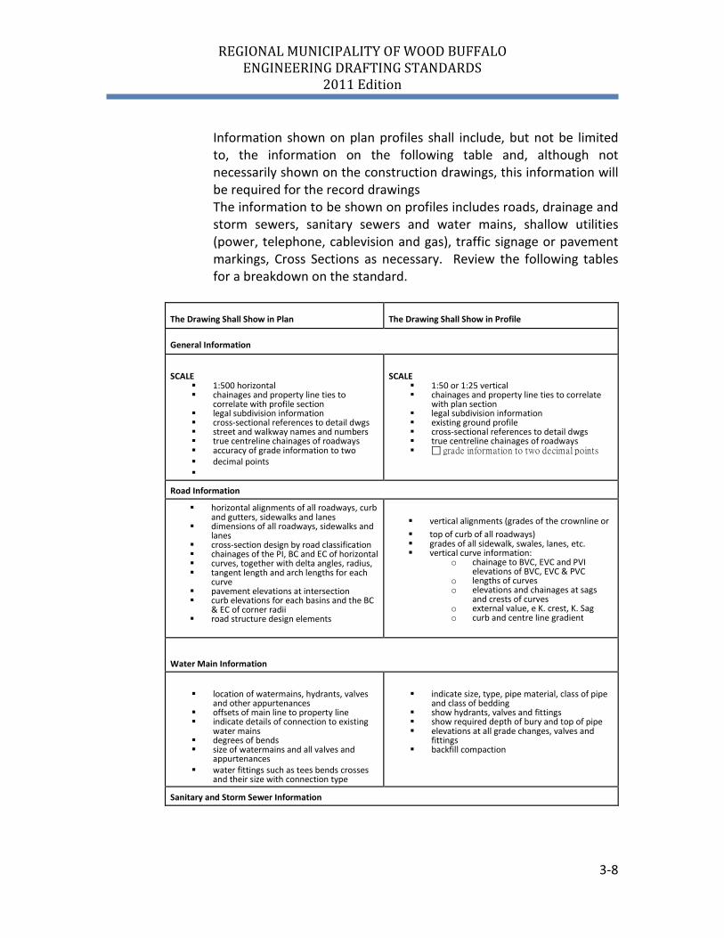
Information shown on plan profiles shall include, but not be limited to, the information on the following table and, although not necessarily shown on the construction drawings, this information will be required for the record drawings The information to be shown on profiles includes roads, drainage and storm sewers, sanitary sewers and water mains, shallow utilities (power, telephone, cablevision and gas), traffic signage or pavement markings, Cross Sections as necessary. Review the following tables for a breakdown on the standard.
The Drawing Shall Show in Plan The Drawing Shall Show in Profile
General Information
SCALE
1:500 horizontal chainages and property line ties to
correlate with profile section legal subdivision information cross-sectional references to detail dwgs street and walkway names and numbers true centreline chainages of roadways accuracy of grade information to two decimal points
SCALE
1:50 or 1:25 vertical chainages and property line ties to correlate
with plan section legal subdivision information existing ground profile cross-sectional references to detail dwgs true centreline chainages of roadways grade information to two decimal points
Road Information
horizontal alignments of all roadways, curb and gutters, sidewalks and lanes
dimensions of all roadways, sidewalks and lanes
cross-section design by road classification chainages of the PI, BC and EC of horizontal curves, together with delta angles, radius, tangent length and arch lengths for each
curve pavement elevations at intersection curb elevations for each basins and the BC
& EC of corner radii road structure design elements
vertical alignments (grades of the crownline or top of curb of all roadways) grades of all sidewalk, swales, lanes, etc. vertical curve information:
o chainage to BVC, EVC and PVI elevations of BVC, EVC & PVC
o lengths of curves o elevations and chainages at sags
and crests of curves o external value, e K. crest, K. Sag o curb and centre line gradient
Water Main Information
location of watermains, hydrants, valves
and other appurtenances offsets of main line to property line indicate details of connection to existing
water mains degrees of bends size of watermains and all valves and
appurtenances water fittings such as tees bends crosses
and their size with connection type
indicate size, type, pipe material, class of pipe
and class of bedding show hydrants, valves and fittings show required depth of bury and top of pipe elevations at all grade changes, valves and
fittings backfill compaction
Sanitary and Storm Sewer Information
REGIONAL MUNICIPALITY OF WOOD BUFFALO ENGINEERING DRAFTING STANDARDS
2011 Edition
3-9
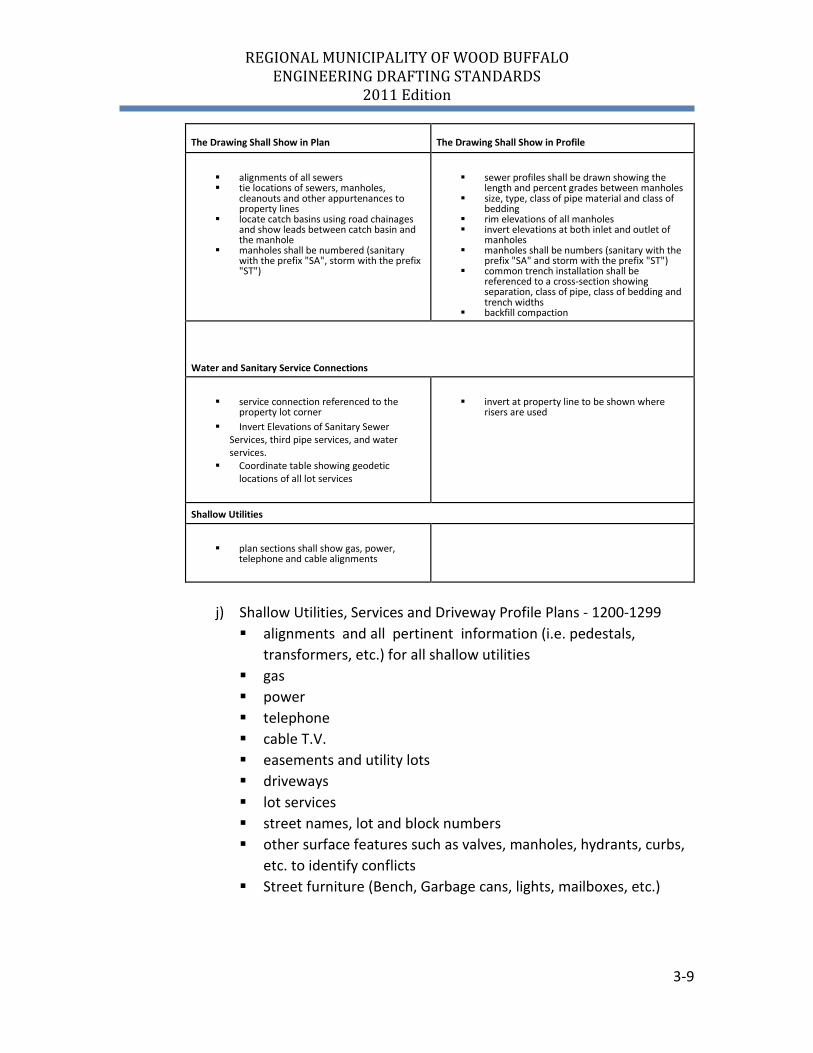
The Drawing Shall Show in Plan The Drawing Shall Show in Profile
alignments of all sewers tie locations of sewers, manholes,
cleanouts and other appurtenances to property lines
locate catch basins using road chainages and show leads between catch basin and the manhole
manholes shall be numbered (sanitary with the prefix "SA", storm with the prefix "ST")
sewer profiles shall be drawn showing the
length and percent grades between manholes size, type, class of pipe material and class of
bedding rim elevations of all manholes invert elevations at both inlet and outlet of
manholes manholes shall be numbers (sanitary with the
prefix "SA" and storm with the prefix "ST") common trench installation shall be
referenced to a cross-section showing separation, class of pipe, class of bedding and trench widths
backfill compaction
Water and Sanitary Service Connections
service connection referenced to the
property lot corner Invert Elevations of Sanitary Sewer
Services, third pipe services, and water services.
Coordinate table showing geodetic locations of all lot services
invert at property line to be shown where
risers are used
Shallow Utilities
plan sections shall show gas, power,
telephone and cable alignments
j) Shallow Utilities, Services and Driveway Profile Plans - 1200-1299 alignments and all pertinent information (i.e. pedestals,
transformers, etc.) for all shallow utilities gas power telephone cable T.V. easements and utility lots driveways lot services street names, lot and block numbers other surface features such as valves, manholes, hydrants, curbs,
etc. to identify conflicts Street furniture (Bench, Garbage cans, lights, mailboxes, etc.)
REGIONAL MUNICIPALITY OF WOOD BUFFALO ENGINEERING DRAFTING STANDARDS
2011 Edition
3-10
k) Landscape Drawings - 1300-1399 Existing and proposed contours at 0.5m intervals within the site
and extending 3 meters beyond, as well as, all other grading detail.
Site boundaries. Temporary site access, laydown areas, parking. Stockpile locations. All existing and proposed utility information. Existing vegetation and/or other natural features to remain. Existing trees to be relocated. Proposed plant material illustrated at 2/3 the mature spread or
diameter, as noted in the Alberta Horticulture Guide, current edition.
Plant schedules, including overall quantities. (may be added in details section also)
Areas to be sodded and seeded with seed mix specified. Type and depth of mulch for shrub beds and tree wells. Location of proposed site furnishings and related construction. Areas of concrete, asphalt or special paving. Irrigation systems where applicable. Fencing locations and construction details. (may be added in
details section also) Locations of bollards along PUL walks or trails. Street lights and park lighting where applicable. Trail locations, signage, and proposed drainage. Adjacent land use information. Total measurements (square meters) of shrubs beds, flowerbeds,
islands, buffers, PUL’s, MR’s and parks). Total measurements (square meters) of sodded and seeded areas.
These plans are to be submitted with the engineering drawings for each phase. See Section 10, Landscape and Park Development Standards, in the Engineering Servicing Standards for additional information. See the Engineering Servicing Standards and Development Procedures Manual for further clarity.
l) Details/General Notes Plan - 1400-1499 Details and sections required to construct the plan set.
REGIONAL MUNICIPALITY OF WOOD BUFFALO ENGINEERING DRAFTING STANDARDS
2011 Edition
3-11
m) Building Structural Plans – 1500-1599 Drawings related to building structural plans
n) Building Mechanical Plans– 1600-1699 Drawings related to building mechanical plans
o) Building Electrical Plans – 1700-1799 Drawings related to building electrical plans
p) Calculations Plan - 1800-1899 Storm, Sanitary, Water or any other calculations which were
completed to prove the validity of design. q) Additional Plans – 1900-2999 Additional plans not mentioned above
.2 Special Requirements for Design Drawings
The design drawings shall be supplemented with the following details: i) details of special protection for pipe sections which are exposed
to high velocities or which require corrosion protection or insulation
ii) drawings required for obtaining permits for the crossings of oil, gas, power transmission lines or railroads and highways
iii) details of placement on fill, tunneling, or pipe jacking, if such special methods are envisaged
iv) thrust block details
.3 Requirements for Network Diagrams The sanitary sewer and storm sewer network diagrams shall include the following information: i) all manholes and size of sewer sections ii) length of sewer section in metres iii) grade of sewer sections iv) total length of tributary sewers in metres for each sewer section v) tributary area in hectares, coefficient of run-off for each storm
sewer section area (tributary areas to be cross-referenced to any summary tables)
vi) estimated peak loading based on tributary area and infiltration in litres per second
vii) Manning velocity for full flow in litres per second viii) Manning design flow in litres per second
REGIONAL MUNICIPALITY OF WOOD BUFFALO ENGINEERING DRAFTING STANDARDS
2011 Edition
3-12
ix) Invert elevation of manholes and catch basins
.4 All drawings shall include the project number assigned by the RMWB and follow sheet numbering conventions as set out in Section 3.5.5.
.5 The drawings shall be neat and legible with adequate clearance margins
between the drawing information and the title block border. Limits of construction and match lines shall be clearly marked on the drawing. See Standard Drawings for examples.
.6 All sheet borders shall be in millimetres (mm) and plotted at 1:1.
3.5.3 Units
.1 All drawings shall be metric. Units will be set to meters to azimuth
system with 0° north pointed to 12 o’clock. Degrees will be in decimal degrees and measured clockwise. Drawing scales and dimensions shall be shown on all drawings.
.2 All elevations shown on drawings shall be metric geodetic datum. The
source and location of the datum used shall be clearly noted on each drawing they appear on.
.3 Lettering shall be vertical upper case lettering. Lettering shall be
unobstructed by linework and other drawing information. Conflicts between linework, symbols, dimensioning or text shall be removed.
.4 Numerical values shown on the drawings shall be shown to two decimal
places unless accuracy warrants otherwise. .5 All objects colour and linetype properties should be set to by-layer. 3.5.4 Notes .1 Construction notes shall be boxed and located around the perimeter of
the drawing, tagged to the drawing feature, in sufficient detail to facilitate construction.
.2 The following notes shall be shown on either the index plan or the first
drawing of the set:
REGIONAL MUNICIPALITY OF WOOD BUFFALO ENGINEERING DRAFTING STANDARDS
2011 Edition
3-13
“All work and materials are as described in the Regional Municipality of Wood Buffalo Manual of ‘Engineering Servicing Standards and Development Procedures’ or as otherwise approved by the Manager of Development Services in the Engineering Department.” “Connection to, or alteration of, existing Municipal-owned utilities, requires authorization by the Manager of Development Services in the Engineering Department.”
.3 Standard details such as manholes, catch basins, hydrants, etc., that are shown and described in the Municipal Standard Drawings need not be shown in detail on the drawings; the Standard Drawing No. shall be quoted on the plan for reference.
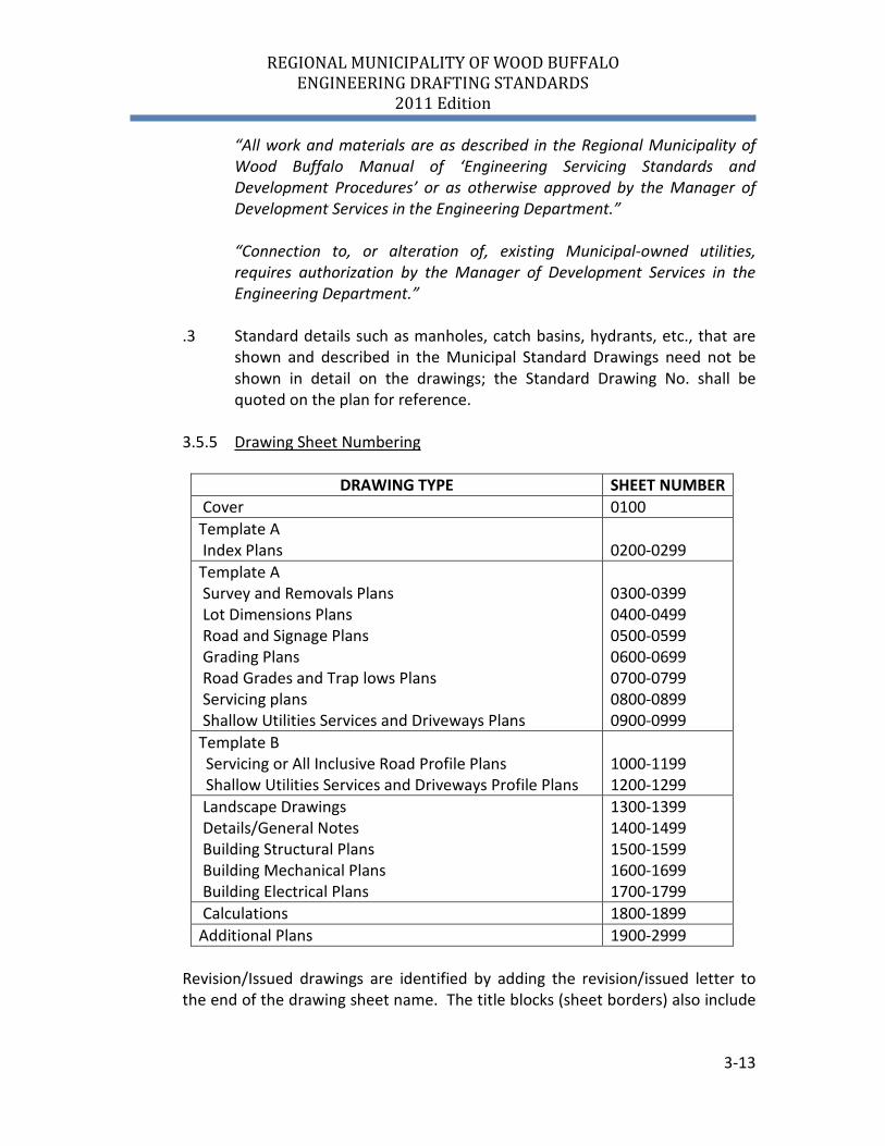
3.5.5 Drawing Sheet Numbering
DRAWING TYPE SHEET NUMBER
Cover 0100 Template A Index Plans
0200-0299
Template A Survey and Removals Plans Lot Dimensions Plans Road and Signage Plans Grading Plans Road Grades and Trap lows Plans Servicing plans Shallow Utilities Services and Driveways Plans
0300-0399 0400-0499 0500-0599 0600-0699 0700-0799 0800-0899 0900-0999
Template B Servicing or All Inclusive Road Profile Plans Shallow Utilities Services and Driveways Profile Plans
1000-1199 1200-1299
Landscape Drawings Details/General Notes Building Structural Plans Building Mechanical Plans Building Electrical Plans
1300-1399 1400-1499 1500-1599 1600-1699 1700-1799
Calculations 1800-1899 Additional Plans 1900-2999
Revision/Issued drawings are identified by adding the revision/issued letter to the end of the drawing sheet name. The title blocks (sheet borders) also include
REGIONAL MUNICIPALITY OF WOOD BUFFALO ENGINEERING DRAFTING STANDARDS
2011 Edition
3-14
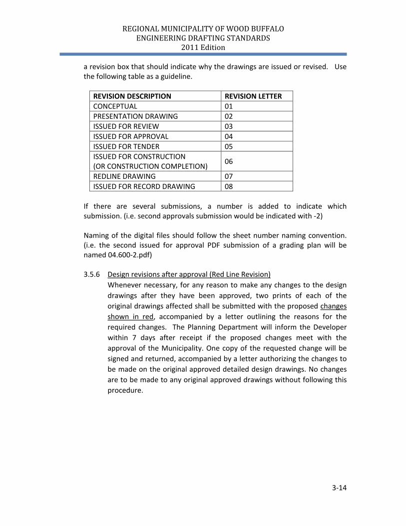
a revision box that should indicate why the drawings are issued or revised. Use the following table as a guideline.
If there are several submissions, a number is added to indicate which submission. (i.e. second approvals submission would be indicated with -2) Naming of the digital files should follow the sheet number naming convention. (i.e. the second issued for approval PDF submission of a grading plan will be named 04.600-2.pdf)
3.5.6 Design revisions after approval (Red Line Revision) Whenever necessary, for any reason to make any changes to the design
drawings after they have been approved, two prints of each of the original drawings affected shall be submitted with the proposed changes shown in red, accompanied by a letter outlining the reasons for the required changes. The Planning Department will inform the Developer within 7 days after receipt if the proposed changes meet with the approval of the Municipality. One copy of the requested change will be signed and returned, accompanied by a letter authorizing the changes to be made on the original approved detailed design drawings. No changes are to be made to any original approved drawings without following this procedure.
REVISION DESCRIPTION REVISION LETTER CONCEPTUAL 01 PRESENTATION DRAWING 02 ISSUED FOR REVIEW 03 ISSUED FOR APPROVAL 04 ISSUED FOR TENDER 05 ISSUED FOR CONSTRUCTION (OR CONSTRUCTION COMPLETION) 06
REDLINE DRAWING 07 ISSUED FOR RECORD DRAWING 08
REGIONAL MUNICIPALITY OF WOOD BUFFALO ENGINEERING DRAFTING STANDARDS
2011 Edition
4-1
4.0 CAD CONVENTIONS 4.1 Layer Naming Conventions
Layers are used to sort the data types being depicted by the linework (Not to sort lineweights, linetypes, colours or other schemes). The RMWB layering standards must be used to create layers to accommodate groupings of related data. Layer naming conventions for existing and proposed conditions shall be adhered to. In the event that new layers are required, the consultant shall create the layer name using the standard layer naming convention.
The layer name structure consists of at least 4 fields separated by underscores. The 4 fields consist of the status field, the group feature field and the descriptive field.
.1 Status Field Prefix X- Existing (All existing layers will begin with X-) P- Proposed (All proposed layers will begin with P-)
F- Future (All future layers will begin with F-) All record (as-built) information will have the P- removed and will be replaced by X- and any layers and linework used for temporary works will be deleted and purged before submission.
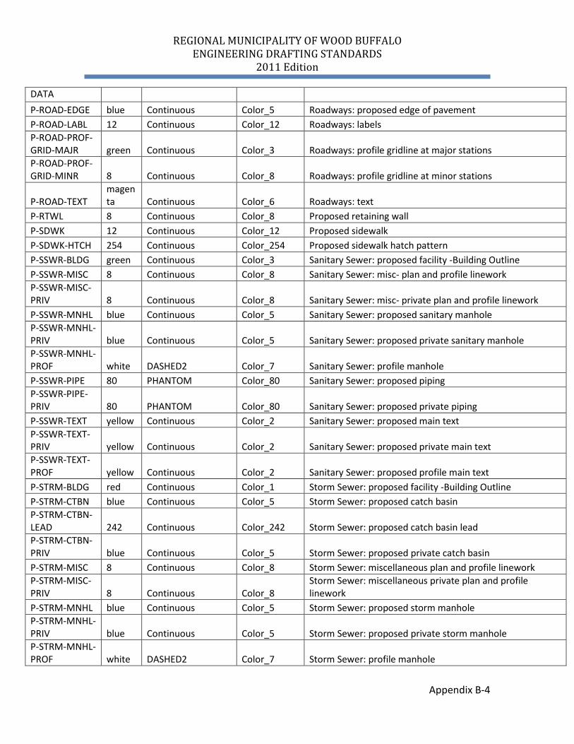
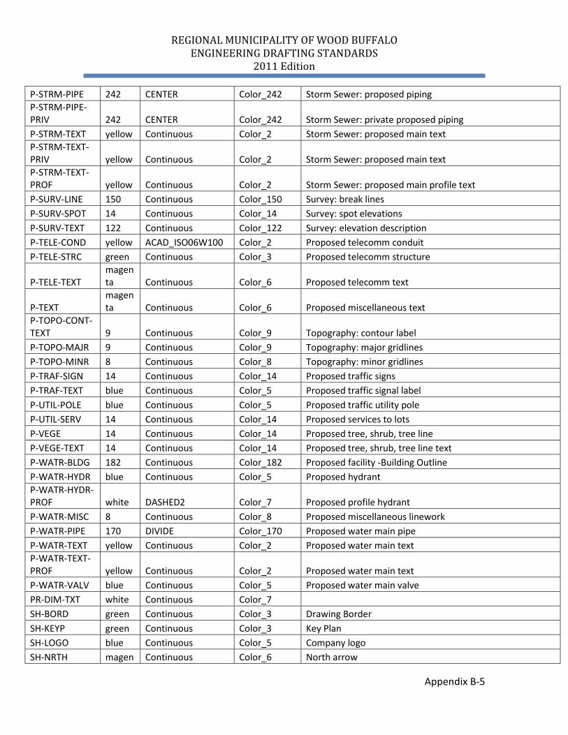
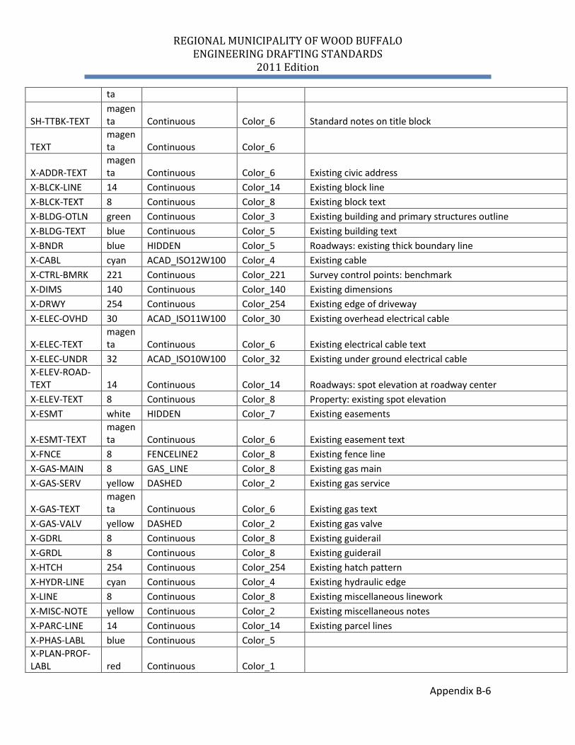
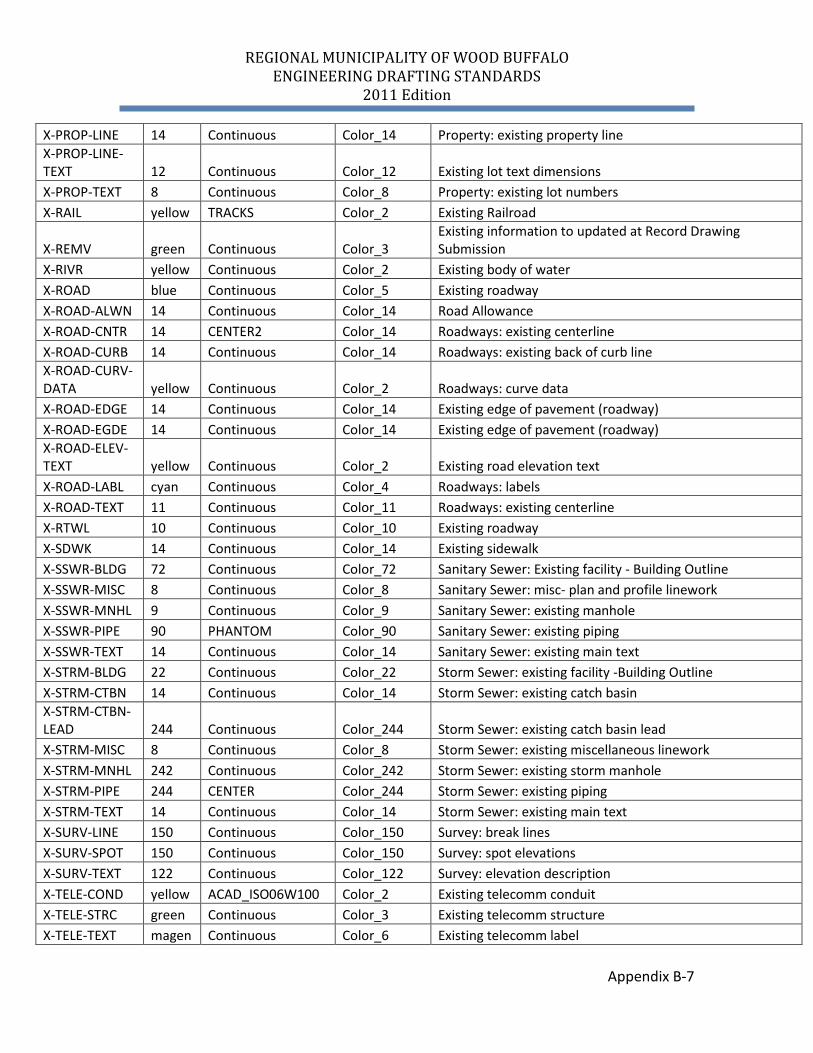
See Appendix B for a list of the standard layering conventions.
4.1.1 Provisions for Creating New Layers As all possibilities are not covered in the existing layer list, it is sometimes possible (and necessary) to create new layer names for some objects. The rules for creation of new layers are:
a) Proper Standard Layer for object must not already exist. b) Must follow standard format c) Must use existing Status Field (X-STRM-TEXT) d) Must use existing Group Feature Field (X-STRM-TEXT) e) Use 4 letter description in the Descriptive Field (X-STRM-CASE)
4.2 Plotting Conventions .1 The RMWB uses colour dependent plot styles (ctb’s) with line weights
assigned to the colours. This will define how the linework looks when plotted. All layer colours shall conform to the RMWB drafting standards.
REGIONAL MUNICIPALITY OF WOOD BUFFALO ENGINEERING DRAFTING STANDARDS
2011 Edition
4-2
4.3 Linetype Conventions
All linetypes shall conform to the RMWB drafting standard, custom linetypes. Drawings must not contain linetypes or complex linetypes other than those defined in RMWB-ENGINEERING.ctb supplied by RMWB. RMWB-ENGINEERING.ctb The linetypes are all converted to metric and formatted to display properly at a 1:1000 scale, with ltscale set to 1, psltscale set to 1. Setting your scales to 1 will cause the linetypes to automatically scale to your viewport scale, ensuring that they will appear at the appropriate size. See Appendix C for Linetype Libraries.
4.4 Block Conventions
AutoCAD blocks are used to group entities. These graphic blocks shall not be exploded. Blocks representing simple objects or simple symbols shall not contain nested blocks (blocks made of blocks). Most symbols should be created with linetype and colour "Bylayer". This allows complete control over the appearance of the symbol. By default the symbol will take on the properties of the layer it is placed on but it can be changed to suit requirements independent of the layer settings.
Newly created blocks should have the following properties: Insertion point at 0,0,0 All objects drawn on layer 0 All blocks must have a node in the center point of the block Any blocks required but not shown may be created. As long as they prescribe to the above conditions and appear in a legend. See Appendix D for Block Libraries.
4.5 Hatching Common hatching patterns are shown in Appendix E. Hatching shall be shown on cross sections to differentiate between materials. Overall plan drawings may contain some hatching if needed for clarity.
REGIONAL MUNICIPALITY OF WOOD BUFFALO ENGINEERING DRAFTING STANDARDS
2011 Edition
4-3
4.6 Details Do NOT include Regional Municipality of Wood Buffalo Engineering Servicing Standards and Development Procedures details with your drawing submission detail sheets. The RMWB details can be referenced in the construction notes. If it is necessary to make a change to a standard detail, the detail will be included on the detail sheet with revisions shown in bold to alleviate confusion. Any additional details not in the Engineering Servicing Standards and Development Procedures will be included on the detail sheets.
4.7 Annotation
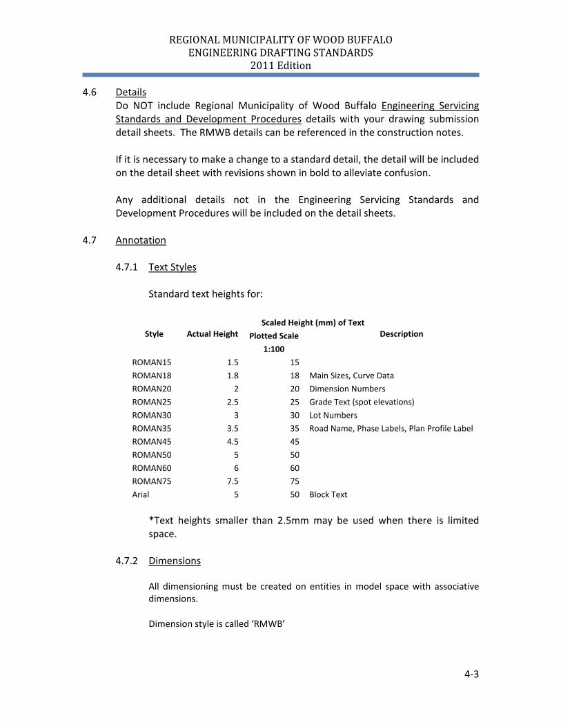
4.7.1 Text Styles Standard text heights for:
Scaled Height (mm) of Text
Style Actual Height Plotted Scale Description
1:100 ROMAN15 1.5 15 ROMAN18 1.8 18 Main Sizes, Curve Data ROMAN20 2 20 Dimension Numbers ROMAN25 2.5 25 Grade Text (spot elevations) ROMAN30 3 30 Lot Numbers ROMAN35 3.5 35 Road Name, Phase Labels, Plan Profile Label ROMAN45 4.5 45 ROMAN50 5 50 ROMAN60 6 60 ROMAN75 7.5 75 Arial 5 50 Block Text
*Text heights smaller than 2.5mm may be used when there is limited space.
4.7.2 Dimensions
All dimensioning must be created on entities in model space with associative dimensions.
Dimension style is called ‘RMWB’
REGIONAL MUNICIPALITY OF WOOD BUFFALO ENGINEERING DRAFTING STANDARDS
2011 Edition
4-4
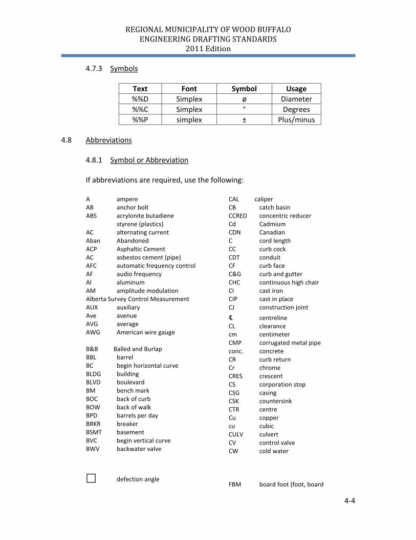
4.7.3 Symbols
Text Font Symbol Usage %%D Simplex ø Diameter %%C Simplex ° Degrees %%P simplex ± Plus/minus
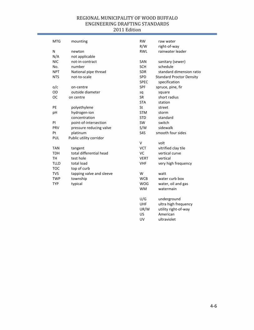
4.8 Abbreviations
4.8.1 Symbol or Abbreviation
If abbreviations are required, use the following:
A ampere AB anchor bolt ABS acrylonite butadiene styrene (plastics) AC alternating current Aban Abandoned ACP Asphaltic Cement AC asbestos cement (pipe) AFC automatic frequency control AF audio frequency Al aluminum AM amplitude modulation
Alberta Survey Control Measurement AUX auxiliary Ave avenue AVG average AWG American wire gauge B&B Balled and Burlap BBL barrel BC begin horizontal curve BLDG building BLVD boulevard BM bench mark BOC back of curb BOW back of walk BPD barrels per day BRKR breaker BSMT basement BVC begin vertical curve BWV backwater valve
CAL caliper CB catch basin CCRED concentric reducer Cd Cadmium CDN Canadian C cord length CC curb cock CDT conduit CF curb face C&G curb and gutter CHC continuous high chair CI cast iron CIP cast in place CJ construction joint ℄ centreline CL clearance cm centimeter CMP corrugated metal pipe conc. concrete CR curb return Cr chrome CRES crescent CS corporation stop CSG casing CSK countersink CTR centre Cu copper cu cubic CULV culvert CV control valve CW cold water
defection angle
FBM board foot (foot, board
REGIONAL MUNICIPALITY OF WOOD BUFFALO ENGINEERING DRAFTING STANDARDS
2011 Edition
4-5
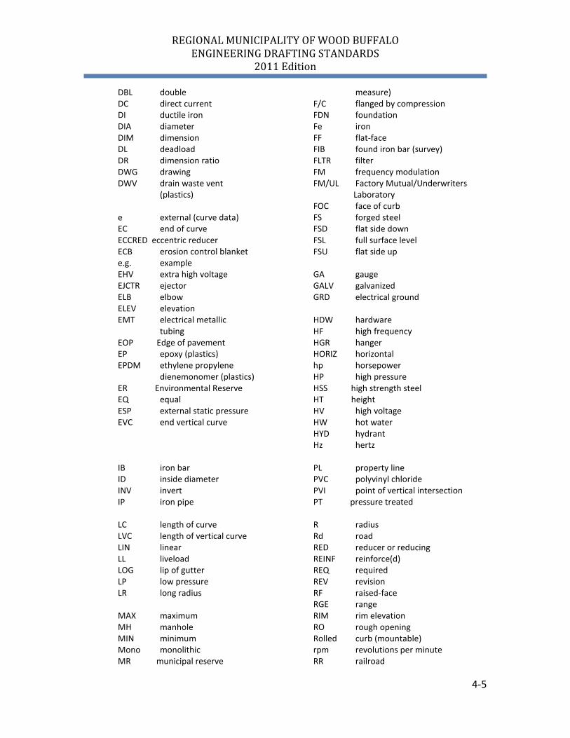
DBL double DC direct current DI ductile iron DIA diameter DIM dimension DL deadload DR dimension ratio DWG drawing DWV drain waste vent (plastics) e external (curve data) EC end of curve ECCRED eccentric reducer ECB erosion control blanket e.g. example EHV extra high voltage EJCTR ejector ELB elbow ELEV elevation EMT electrical metallic tubing EOP Edge of pavement EP epoxy (plastics) EPDM ethylene propylene dienemonomer (plastics) ER Environmental Reserve EQ equal ESP external static pressure EVC end vertical curve
measure) F/C flanged by compression FDN foundation Fe iron FF flat-face FIB found iron bar (survey) FLTR filter FM frequency modulation FM/UL Factory Mutual/Underwriters Laboratory FOC face of curb FS forged steel FSD flat side down FSL full surface level FSU flat side up GA gauge GALV galvanized GRD electrical ground HDW hardware HF high frequency HGR hanger HORIZ horizontal hp horsepower HP high pressure HSS high strength steel HT height HV high voltage HW hot water HYD hydrant Hz hertz
IB iron bar ID inside diameter INV invert IP iron pipe LC length of curve LVC length of vertical curve LIN linear LL liveload LOG lip of gutter LP low pressure LR long radius MAX maximum MH manhole MIN minimum Mono monolithic MR municipal reserve
PL property line PVC polyvinyl chloride PVI point of vertical intersection PT pressure treated R radius Rd road RED reducer or reducing REINF reinforce(d) REQ required REV revision RF raised-face RGE range RIM rim elevation RO rough opening Rolled curb (mountable) rpm revolutions per minute RR railroad
REGIONAL MUNICIPALITY OF WOOD BUFFALO ENGINEERING DRAFTING STANDARDS
2011 Edition
4-6
MTG mounting N newton N/A not applicable NIC not-in-contract No. number NPT National pipe thread NTS not-to-scale o/c on-centre OD outside diameter OC on centre PE polyethylene pH hydrogen-ion concentration PI point-of-intersection PRV pressure reducing valve Pt platinum PUL Public utility corridor TAN tangent TDH total differential head TH test hole TLLD total load TOC top of curb TVS tapping valve and sleeve TWP township TYP typical
RW raw water R/W right-of-way RWL rainwater leader SAN sanitary (sewer) SCH schedule SDR standard dimension ratio SPD Standard Proctor Density SPEC specification SPF spruce, pine, fir sq square SR short radius STA station St street STM storm STD standard SW switch S/W sidewalk S4S smooth four sides V volt VCT vitrified clay tile VC vertical curve VERT vertical VHF very high frequency W watt WCB water curb box WOG water, oil and gas WM watermain U/G underground UHF ultra high frequency UR/W utility right-of-way US American UV ultraviolet
REGIONAL MUNICIPALITY OF WOOD BUFFALO ENGINEERING DRAFTING STANDARDS
2011 Edition
4-7
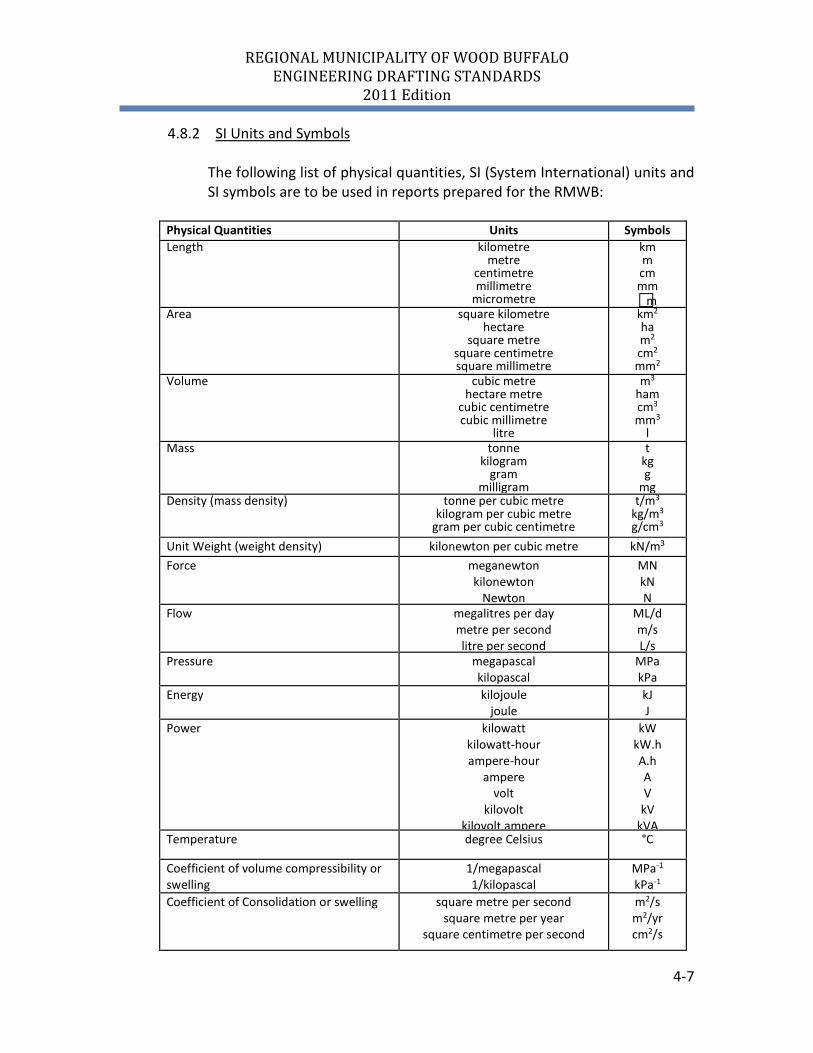
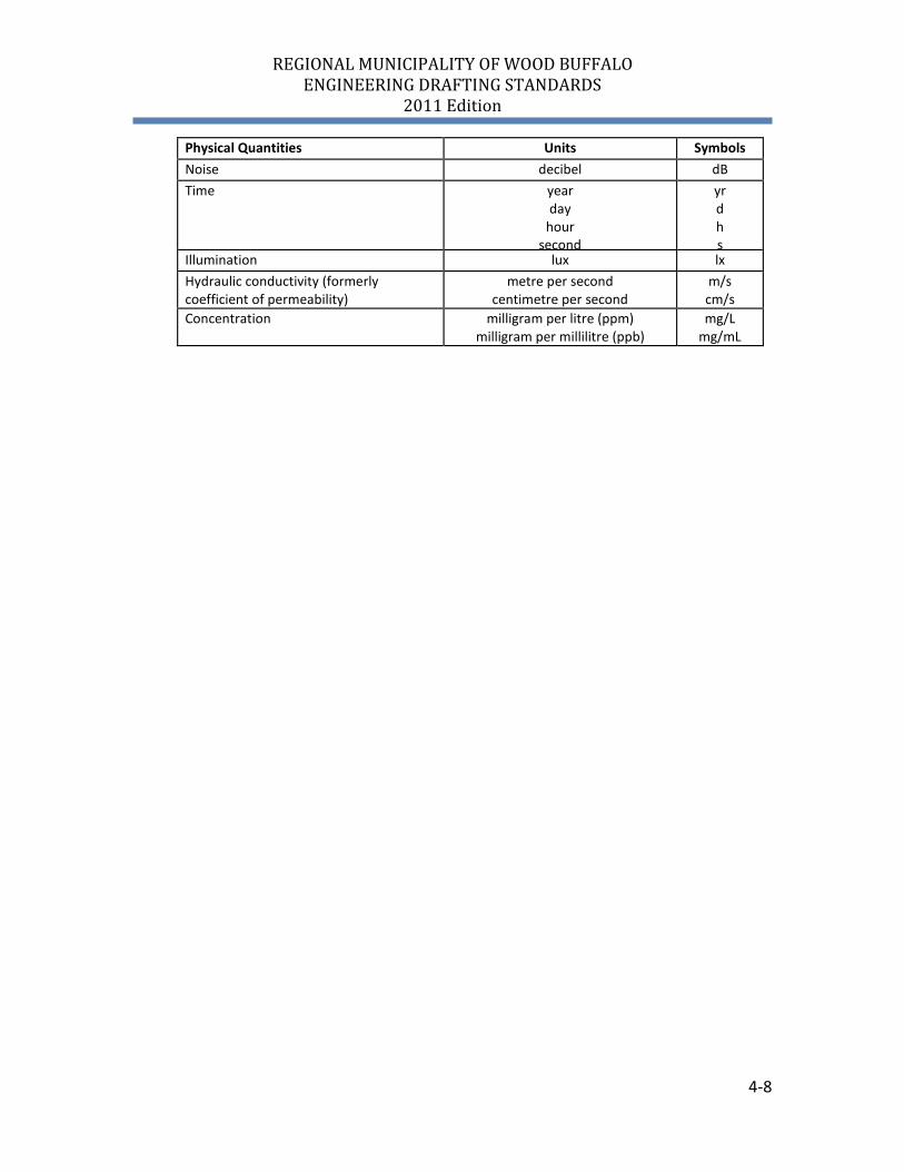
4.8.2 SI Units and Symbols
The following list of physical quantities, SI (System International) units and SI symbols are to be used in reports prepared for the RMWB:
Physical Quantities Units Symbols Length kilometre
metre centimetre millimetre
micrometre
km m cm mm m
Area square kilometre hectare
square metre square centimetre square millimetre
km2 ha m2 cm2 mm2
Volume cubic metre hectare metre
cubic centimetre cubic millimetre
litre
m3 ham cm3 mm3
l Mass tonne
kilogram gram
milligram
t kg g
mg Density (mass density) tonne per cubic metre
kilogram per cubic metre gram per cubic centimetre
t/m3 kg/m3 g/cm3
Unit Weight (weight density) kilonewton per cubic metre kN/m3 Force meganewton
kilonewton Newton
MN kN N
Flow megalitres per day metre per second litre per second
ML/d m/s L/s
Pressure megapascal kilopascal
MPa kPa
Energy kilojoule joule
kJ J
Power kilowatt kilowatt-hour ampere-hour
ampere volt
kilovolt kilovolt ampere
kW kW.h A.h A V
kV kVA
Temperature degree Celsius °C
Coefficient of volume compressibility or swelling
1/megapascal 1/kilopascal
MPa-1 kPa-1
Coefficient of Consolidation or swelling square metre per second square metre per year
square centimetre per second
m2/s m2/yr cm2/s
REGIONAL MUNICIPALITY OF WOOD BUFFALO ENGINEERING DRAFTING STANDARDS
2011 Edition
4-8
Physical Quantities Units Symbols Noise decibel dB Time year
day hour
second
yr d h s
Illumination lux lx Hydraulic conductivity (formerly coefficient of permeability)
metre per second centimetre per second
m/s cm/s
Concentration milligram per litre (ppm) milligram per millilitre (ppb)
mg/L mg/mL
REGIONAL MUNICIPALITY OF WOOD BUFFALO ENGINEERING DRAFTING STANDARDS
2011 Edition
5-1
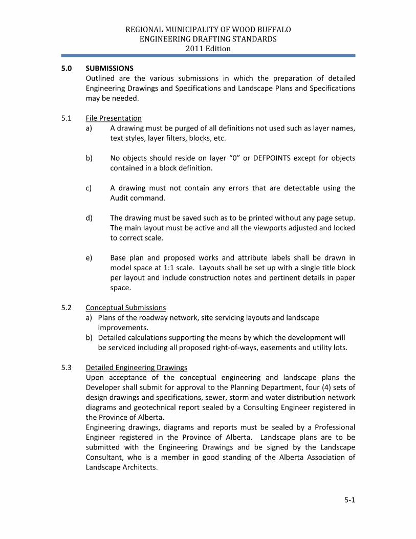
5.0 SUBMISSIONS Outlined are the various submissions in which the preparation of detailed Engineering Drawings and Specifications and Landscape Plans and Specifications may be needed.
5.1 File Presentation
a) A drawing must be purged of all definitions not used such as layer names, text styles, layer filters, blocks, etc.
b) No objects should reside on layer “0” or DEFPOINTS except for objects
contained in a block definition. c) A drawing must not contain any errors that are detectable using the
Audit command. d) The drawing must be saved such as to be printed without any page setup.
The main layout must be active and all the viewports adjusted and locked to correct scale.
e) Base plan and proposed works and attribute labels shall be drawn in
model space at 1:1 scale. Layouts shall be set up with a single title block per layout and include construction notes and pertinent details in paper space.
5.2 Conceptual Submissions a) Plans of the roadway network, site servicing layouts and landscape
improvements. b) Detailed calculations supporting the means by which the development will
be serviced including all proposed right-of-ways, easements and utility lots.
5.3 Detailed Engineering Drawings Upon acceptance of the conceptual engineering and landscape plans the Developer shall submit for approval to the Planning Department, four (4) sets of design drawings and specifications, sewer, storm and water distribution network diagrams and geotechnical report sealed by a Consulting Engineer registered in the Province of Alberta. Engineering drawings, diagrams and reports must be sealed by a Professional Engineer registered in the Province of Alberta. Landscape plans are to be submitted with the Engineering Drawings and be signed by the Landscape Consultant, who is a member in good standing of the Alberta Association of Landscape Architects.
REGIONAL MUNICIPALITY OF WOOD BUFFALO ENGINEERING DRAFTING STANDARDS
2011 Edition
5-2
Other information required to be submitted in the approval process include but are not limited to:
Traffic Impact Analysis (TIA). Traffic Accommodation Plans
5.4 Record (As-Built) Submissions
The Developer shall submit through E-Permitting record drawings and other related information giving detailed measurements of the actual municipal services constructed. The submission of this data for record purposes is a condition of the issuance of Construction Completion Certificates by the Municipality. Record Drawings may be required in two stages.
5.4.1 General Requirements:
.1 Drawings shall include all information as specified elsewhere for the construction drawings, but shall be corrected upon completion of construction to note all works removed during construction. As an alternative, this information shall be retained in the digital file on layer (X-REMV) but not displayed on the final print. Note abandoned services and reflect As-Built conditions for permanent records.
.2 All dimensions shown shall reflect the As-Built conditions of the
construction and all references to “Proposed” shall be removed. As-Built drawings shall be to scale in accordance with the As-Built dimensions shown. The Revision Table shall be completed indicating the drawings are Record Drawings.
.3 All As-Built features shall be surveyed and survey points imported
into the digital drawing on the appropriate layers (X-SURV-SPOT). The As-Built drawing shall reflect the true elevation and location of all constructed features, in both the plan and profile views. Record (as-built) elevations will be to 2 decimals. See Section 3.4 for more information on survey data submissions.
.4 Excel attribute table to be filled out and included with the digital
submission.
.5 The As-Built drawings shall be submitted as follows: a) Municipal Standard AutoCAD format b) A pdf version.
REGIONAL MUNICIPALITY OF WOOD BUFFALO ENGINEERING DRAFTING STANDARDS
2011 Edition
5-3
c) A csv file of any survey information d) One full size set on bond paper signed and sealed. e) Excel attribute table Please submit digital submissions through e-permitting or by CD. .6 Line work for all constructed works shown on the drawings shall
retain the thicker line density for ease of determining the extent of works covered by the drawings. Proposed construction for future phases of the project shall not be shown on the As-Built drawings.
.7 All As-Built drawings shall also include the following information:
a) The location and elevation of all existing utilities and services
encountered in the construction operation, b) The location and invert elevation at property line of all
individual service connections, and the tee chainage, at the main for all constructed and existing works,
c) A note on each drawing describing the type of trench material (sand, gravel, clay, etc.) encountered during construction and the location and profile of all rock.
.8 All service connections that are not located at the center of the
lot shall be shown with dimensions to property lines. Private services will also be shown on the drawings with labels indicated “private”.
.9 See Appendix F for Submission Compliance Checklist
5.4.2 Interim Stage On completion of the sanitary and storm sewer systems, the water
distribution system and lot services the Developer shall submit to the Engineering Services Division two (2) full size sets of as-constructed drawings on bond paper as well as an electronic copy in RMWB's current AutoCAD format.
5.4.3 Completed Stage Within thirty (30) days of satisfactory completion of surface
improvements and as a condition of the issuance of Construction Completion Certificate for surface improvements the Developer shall submit to the Engineering Division the following information:
REGIONAL MUNICIPALITY OF WOOD BUFFALO ENGINEERING DRAFTING STANDARDS
2011 Edition
5-4
• Certification by the Consulting Engineer that all work has been
completed in accordance with the plans and specifications, the Engineering Servicing Standards and that all work and deficiencies have been completed.
• One set of digital copies (PDF & DWG) of as constructed drawings
sealed by a professional engineer registered in the Province of Alberta and complete with a “Certificate of Compliance”. At this stage, the drawing shall be stamped "As-built Drawings for all Municipal Improvements".
• All previously unsubmitted certificates concerning materials
inspection and testing, mix designs, deflection test, concrete strength tests, compaction tests, infiltration, exfiltration, light, video-inspection tests, as required by this document and by the Municipality.
• Completed tender document as tendered by the successful contractor
and a copy of the Final Progress Payment Certificate. Upon acceptance of this data, the Developer may request a construction completion inspection and within thirty (30) days of such request, the Municipality will carry out an inspection for issuance of the Construction Completion Certificate. Should seasonal conditions not permit the inspection, execution of the Construction Completion Certificate, by the Municipality, will be delayed until appropriate conditions exist and/or conditional acceptance may be granted based on the Consulting Engineer’s Certification.
5.4.4 Additional Information Record drawings will be of the same format as the original construction drawings with all changes noted and the following information added: • Design data is erased on original and replaced with record data. • All hydrants, valves, curb stops, manholes and catch basins are to be
dimensioned in two directions or labelled with a Northing and Easting coordinate.
REGIONAL MUNICIPALITY OF WOOD BUFFALO ENGINEERING DRAFTING STANDARDS
2011 Edition
Appendix A-1
APPENDIX A
AREA ABBREVIATIONS TABLE
REGIONAL MUNICIPALITY OF WOOD BUFFALO ENGINEERING DRAFTING STANDARDS
2011 Edition
Appendix A-2
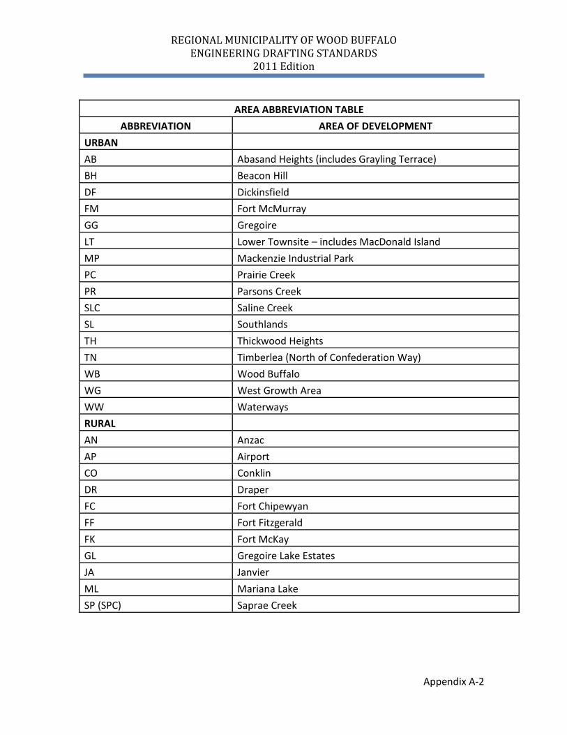
AREA ABBREVIATION TABLE
ABBREVIATION AREA OF DEVELOPMENT URBAN AB Abasand Heights (includes Grayling Terrace) BH Beacon Hill DF Dickinsfield FM Fort McMurray GG Gregoire LT Lower Townsite – includes MacDonald Island MP Mackenzie Industrial Park PC Prairie Creek PR Parsons Creek SLC Saline Creek SL Southlands TH Thickwood Heights TN Timberlea (North of Confederation Way) WB Wood Buffalo WG West Growth Area WW Waterways RURAL AN Anzac AP Airport CO Conklin DR Draper FC Fort Chipewyan FF Fort Fitzgerald FK Fort McKay GL Gregoire Lake Estates JA Janvier ML Mariana Lake SP (SPC) Saprae Creek
REGIONAL MUNICIPALITY OF WOOD BUFFALO ENGINEERING DRAFTING STANDARDS
2011 Edition
Appendix B-1
APPENDIX B
CAD CONVENTIONS
REGIONAL MUNICIPALITY OF WOOD BUFFALO ENGINEERING DRAFTING STANDARDS
2011 Edition
Appendix B-2
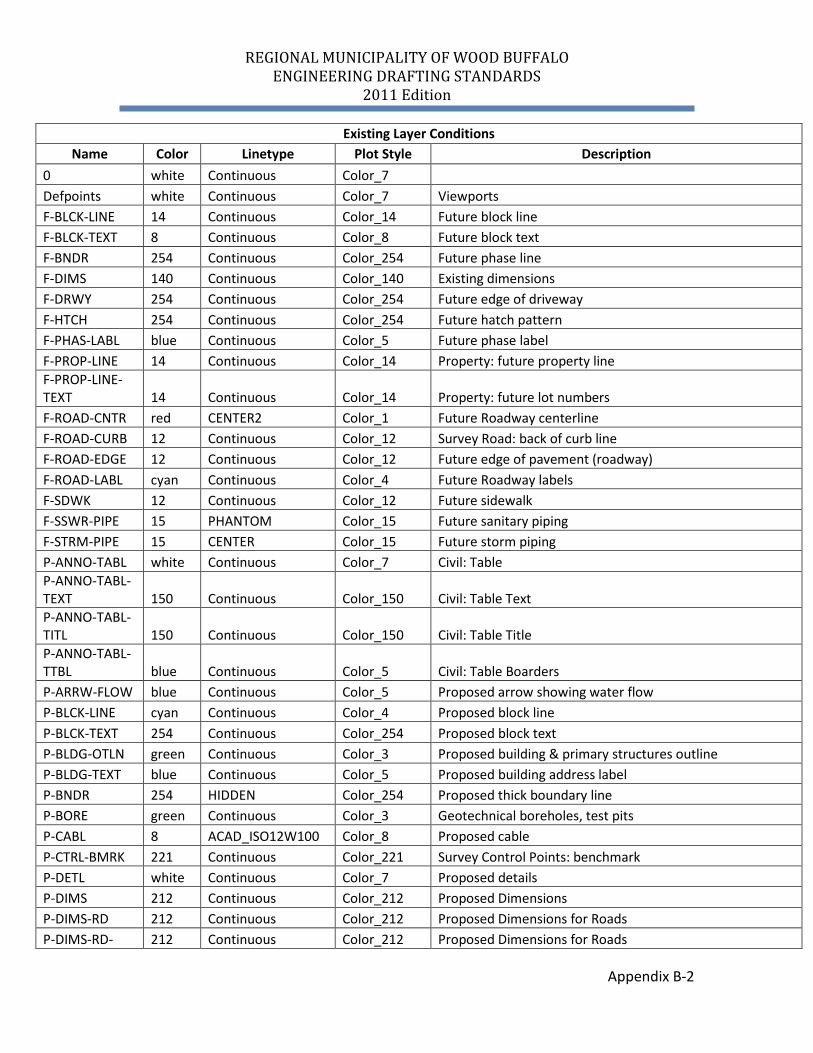
Existing Layer Conditions Name Color Linetype Plot Style Description
0 white Continuous Color_7 Defpoints white Continuous Color_7 Viewports F-BLCK-LINE 14 Continuous Color_14 Future block line F-BLCK-TEXT 8 Continuous Color_8 Future block text F-BNDR 254 Continuous Color_254 Future phase line F-DIMS 140 Continuous Color_140 Existing dimensions F-DRWY 254 Continuous Color_254 Future edge of driveway F-HTCH 254 Continuous Color_254 Future hatch pattern F-PHAS-LABL blue Continuous Color_5 Future phase label F-PROP-LINE 14 Continuous Color_14 Property: future property line F-PROP-LINE-TEXT 14 Continuous Color_14 Property: future lot numbers F-ROAD-CNTR red CENTER2 Color_1 Future Roadway centerline F-ROAD-CURB 12 Continuous Color_12 Survey Road: back of curb line F-ROAD-EDGE 12 Continuous Color_12 Future edge of pavement (roadway) F-ROAD-LABL cyan Continuous Color_4 Future Roadway labels F-SDWK 12 Continuous Color_12 Future sidewalk F-SSWR-PIPE 15 PHANTOM Color_15 Future sanitary piping F-STRM-PIPE 15 CENTER Color_15 Future storm piping P-ANNO-TABL white Continuous Color_7 Civil: Table P-ANNO-TABL-TEXT 150 Continuous Color_150 Civil: Table Text P-ANNO-TABL-TITL 150 Continuous Color_150 Civil: Table Title P-ANNO-TABL-TTBL blue Continuous Color_5 Civil: Table Boarders P-ARRW-FLOW blue Continuous Color_5 Proposed arrow showing water flow P-BLCK-LINE cyan Continuous Color_4 Proposed block line P-BLCK-TEXT 254 Continuous Color_254 Proposed block text P-BLDG-OTLN green Continuous Color_3 Proposed building & primary structures outline P-BLDG-TEXT blue Continuous Color_5 Proposed building address label P-BNDR 254 HIDDEN Color_254 Proposed thick boundary line P-BORE green Continuous Color_3 Geotechnical boreholes, test pits P-CABL 8 ACAD_ISO12W100 Color_8 Proposed cable P-CTRL-BMRK 221 Continuous Color_221 Survey Control Points: benchmark P-DETL white Continuous Color_7 Proposed details P-DIMS 212 Continuous Color_212 Proposed Dimensions P-DIMS-RD 212 Continuous Color_212 Proposed Dimensions for Roads P-DIMS-RD- 212 Continuous Color_212 Proposed Dimensions for Roads
REGIONAL MUNICIPALITY OF WOOD BUFFALO ENGINEERING DRAFTING STANDARDS
2011 Edition
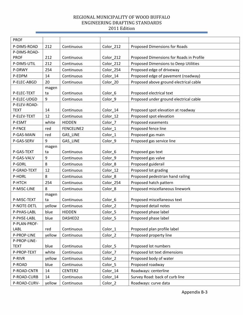
Appendix B-3
PROF P-DIMS-ROAD 212 Continuous Color_212 Proposed Dimensions for Roads P-DIMS-ROAD-PROF 212 Continuous Color_212 Proposed Dimensions for Roads in Profile P-DIMS-UTIL 212 Continuous Color_212 Proposed Dimensions to Deep Utilities P-DRWY 254 Continuous Color_254 Proposed edge of driveway P-EDPM 14 Continuous Color_14 Proposed edge of pavement (roadway) P-ELEC-ABGD 20 Continuous Color_20 Proposed above ground electrical cable
P-ELEC-TEXT magenta Continuous Color_6 Proposed electrical text
P-ELEC-UDGD 9 Continuous Color_9 Proposed under ground electrical cable P-ELEV-ROAD-TEXT 14 Continuous Color_14 Proposed spot elevation at roadway P-ELEV-TEXT 12 Continuous Color_12 Proposed spot elevation P-ESMT white HIDDEN Color_7 Proposed easements P-FNCE red FENCELINE2 Color_1 Proposed fence line P-GAS-MAIN red GAS_LINE Color_1 Proposed gas main P-GAS-SERV 9 GAS_LINE Color_9 Proposed gas service line
P-GAS-TEXT magenta Continuous Color_6 Proposed gas text
P-GAS-VALV 9 Continuous Color_9 Proposed gas valve P-GDRL 8 Continuous Color_8 Proposed guiderail P-GRAD-TEXT 12 Continuous Color_12 Proposed lot grading P-HDRL 8 Continuous Color_8 Proposed pedestrian hand railing P-HTCH 254 Continuous Color_254 Proposed hatch pattern P-MISC-LINE 8 Continuous Color_8 Proposed miscellaneous linework
P-MISC-TEXT magenta Continuous Color_6 Proposed miscellaneous text
P-NOTE-DETL yellow Continuous Color_2 Proposed detail notes P-PHAS-LABL blue HIDDEN Color_5 Proposed phase label P-PHSE-LABL blue DASHED2 Color_5 Proposed phase label P-PLAN-PROF-LABL red Continuous Color_1 Proposed plan profile label P-PROP-LINE yellow Continuous Color_2 Proposed property line P-PROP-LINE-TEXT blue Continuous Color_5 Proposed lot numbers P-PROP-TEXT white Continuous Color_7 Proposed lot text dimensions P-RIVR yellow Continuous Color_2 Proposed body of water P-ROAD blue Continuous Color_5 Proposed roadway P-ROAD-CNTR 14 CENTER2 Color_14 Roadways: centerline P-ROAD-CURB 14 Continuous Color_14 Survey Road: back of curb line P-ROAD-CURV- yellow Continuous Color_2 Roadways: curve data
REGIONAL MUNICIPALITY OF WOOD BUFFALO ENGINEERING DRAFTING STANDARDS
2011 Edition
Appendix B-4
DATA P-ROAD-EDGE blue Continuous Color_5 Roadways: proposed edge of pavement P-ROAD-LABL 12 Continuous Color_12 Roadways: labels P-ROAD-PROF-GRID-MAJR green Continuous Color_3 Roadways: profile gridline at major stations P-ROAD-PROF-GRID-MINR 8 Continuous Color_8 Roadways: profile gridline at minor stations
P-ROAD-TEXT magenta Continuous Color_6 Roadways: text
P-RTWL 8 Continuous Color_8 Proposed retaining wall P-SDWK 12 Continuous Color_12 Proposed sidewalk P-SDWK-HTCH 254 Continuous Color_254 Proposed sidewalk hatch pattern P-SSWR-BLDG green Continuous Color_3 Sanitary Sewer: proposed facility -Building Outline P-SSWR-MISC 8 Continuous Color_8 Sanitary Sewer: misc- plan and profile linework P-SSWR-MISC-PRIV 8 Continuous Color_8 Sanitary Sewer: misc- private plan and profile linework P-SSWR-MNHL blue Continuous Color_5 Sanitary Sewer: proposed sanitary manhole P-SSWR-MNHL-PRIV blue Continuous Color_5 Sanitary Sewer: proposed private sanitary manhole P-SSWR-MNHL-PROF white DASHED2 Color_7 Sanitary Sewer: profile manhole P-SSWR-PIPE 80 PHANTOM Color_80 Sanitary Sewer: proposed piping P-SSWR-PIPE-PRIV 80 PHANTOM Color_80 Sanitary Sewer: proposed private piping P-SSWR-TEXT yellow Continuous Color_2 Sanitary Sewer: proposed main text P-SSWR-TEXT-PRIV yellow Continuous Color_2 Sanitary Sewer: proposed private main text P-SSWR-TEXT-PROF yellow Continuous Color_2 Sanitary Sewer: proposed profile main text P-STRM-BLDG red Continuous Color_1 Storm Sewer: proposed facility -Building Outline P-STRM-CTBN blue Continuous Color_5 Storm Sewer: proposed catch basin P-STRM-CTBN-LEAD 242 Continuous Color_242 Storm Sewer: proposed catch basin lead P-STRM-CTBN-PRIV blue Continuous Color_5 Storm Sewer: proposed private catch basin P-STRM-MISC 8 Continuous Color_8 Storm Sewer: miscellaneous plan and profile linework P-STRM-MISC-PRIV 8 Continuous Color_8
Storm Sewer: miscellaneous private plan and profile linework
P-STRM-MNHL blue Continuous Color_5 Storm Sewer: proposed storm manhole P-STRM-MNHL-PRIV blue Continuous Color_5 Storm Sewer: proposed private storm manhole P-STRM-MNHL-PROF white DASHED2 Color_7 Storm Sewer: profile manhole
REGIONAL MUNICIPALITY OF WOOD BUFFALO ENGINEERING DRAFTING STANDARDS
2011 Edition
Appendix B-5
P-STRM-PIPE 242 CENTER Color_242 Storm Sewer: proposed piping P-STRM-PIPE-PRIV 242 CENTER Color_242 Storm Sewer: private proposed piping P-STRM-TEXT yellow Continuous Color_2 Storm Sewer: proposed main text P-STRM-TEXT-PRIV yellow Continuous Color_2 Storm Sewer: proposed main text P-STRM-TEXT-PROF yellow Continuous Color_2 Storm Sewer: proposed main profile text P-SURV-LINE 150 Continuous Color_150 Survey: break lines P-SURV-SPOT 14 Continuous Color_14 Survey: spot elevations P-SURV-TEXT 122 Continuous Color_122 Survey: elevation description P-TELE-COND yellow ACAD_ISO06W100 Color_2 Proposed telecomm conduit P-TELE-STRC green Continuous Color_3 Proposed telecomm structure
P-TELE-TEXT magenta Continuous Color_6 Proposed telecomm text
P-TEXT magenta Continuous Color_6 Proposed miscellaneous text
P-TOPO-CONT-TEXT 9 Continuous Color_9 Topography: contour label P-TOPO-MAJR 9 Continuous Color_9 Topography: major gridlines P-TOPO-MINR 8 Continuous Color_8 Topography: minor gridlines P-TRAF-SIGN 14 Continuous Color_14 Proposed traffic signs P-TRAF-TEXT blue Continuous Color_5 Proposed traffic signal label P-UTIL-POLE blue Continuous Color_5 Proposed traffic utility pole P-UTIL-SERV 14 Continuous Color_14 Proposed services to lots P-VEGE 14 Continuous Color_14 Proposed tree, shrub, tree line P-VEGE-TEXT 14 Continuous Color_14 Proposed tree, shrub, tree line text P-WATR-BLDG 182 Continuous Color_182 Proposed facility -Building Outline P-WATR-HYDR blue Continuous Color_5 Proposed hydrant P-WATR-HYDR-PROF white DASHED2 Color_7 Proposed profile hydrant P-WATR-MISC 8 Continuous Color_8 Proposed miscellaneous linework P-WATR-PIPE 170 DIVIDE Color_170 Proposed water main pipe P-WATR-TEXT yellow Continuous Color_2 Proposed water main text P-WATR-TEXT-PROF yellow Continuous Color_2 Proposed water main text P-WATR-VALV blue Continuous Color_5 Proposed water main valve PR-DIM-TXT white Continuous Color_7 SH-BORD green Continuous Color_3 Drawing Border SH-KEYP green Continuous Color_3 Key Plan SH-LOGO blue Continuous Color_5 Company logo SH-NRTH magen Continuous Color_6 North arrow
REGIONAL MUNICIPALITY OF WOOD BUFFALO ENGINEERING DRAFTING STANDARDS
2011 Edition
Appendix B-6
ta
SH-TTBK-TEXT magenta Continuous Color_6 Standard notes on title block
TEXT magenta Continuous Color_6
X-ADDR-TEXT magenta Continuous Color_6 Existing civic address
X-BLCK-LINE 14 Continuous Color_14 Existing block line X-BLCK-TEXT 8 Continuous Color_8 Existing block text X-BLDG-OTLN green Continuous Color_3 Existing building and primary structures outline X-BLDG-TEXT blue Continuous Color_5 Existing building text X-BNDR blue HIDDEN Color_5 Roadways: existing thick boundary line X-CABL cyan ACAD_ISO12W100 Color_4 Existing cable X-CTRL-BMRK 221 Continuous Color_221 Survey control points: benchmark X-DIMS 140 Continuous Color_140 Existing dimensions X-DRWY 254 Continuous Color_254 Existing edge of driveway X-ELEC-OVHD 30 ACAD_ISO11W100 Color_30 Existing overhead electrical cable
X-ELEC-TEXT magenta Continuous Color_6 Existing electrical cable text
X-ELEC-UNDR 32 ACAD_ISO10W100 Color_32 Existing under ground electrical cable X-ELEV-ROAD-TEXT 14 Continuous Color_14 Roadways: spot elevation at roadway center X-ELEV-TEXT 8 Continuous Color_8 Property: existing spot elevation X-ESMT white HIDDEN Color_7 Existing easements
X-ESMT-TEXT magenta Continuous Color_6 Existing easement text
X-FNCE 8 FENCELINE2 Color_8 Existing fence line X-GAS-MAIN 8 GAS_LINE Color_8 Existing gas main X-GAS-SERV yellow DASHED Color_2 Existing gas service
X-GAS-TEXT magenta Continuous Color_6 Existing gas text
X-GAS-VALV yellow DASHED Color_2 Existing gas valve X-GDRL 8 Continuous Color_8 Existing guiderail X-GRDL 8 Continuous Color_8 Existing guiderail X-HTCH 254 Continuous Color_254 Existing hatch pattern X-HYDR-LINE cyan Continuous Color_4 Existing hydraulic edge X-LINE 8 Continuous Color_8 Existing miscellaneous linework X-MISC-NOTE yellow Continuous Color_2 Existing miscellaneous notes X-PARC-LINE 14 Continuous Color_14 Existing parcel lines X-PHAS-LABL blue Continuous Color_5 X-PLAN-PROF-LABL red Continuous Color_1
REGIONAL MUNICIPALITY OF WOOD BUFFALO ENGINEERING DRAFTING STANDARDS
2011 Edition
Appendix B-7
X-PROP-LINE 14 Continuous Color_14 Property: existing property line X-PROP-LINE-TEXT 12 Continuous Color_12 Existing lot text dimensions X-PROP-TEXT 8 Continuous Color_8 Property: existing lot numbers X-RAIL yellow TRACKS Color_2 Existing Railroad
X-REMV green Continuous Color_3 Existing information to updated at Record Drawing Submission
X-RIVR yellow Continuous Color_2 Existing body of water X-ROAD blue Continuous Color_5 Existing roadway X-ROAD-ALWN 14 Continuous Color_14 Road Allowance X-ROAD-CNTR 14 CENTER2 Color_14 Roadways: existing centerline X-ROAD-CURB 14 Continuous Color_14 Roadways: existing back of curb line X-ROAD-CURV-DATA yellow Continuous Color_2 Roadways: curve data X-ROAD-EDGE 14 Continuous Color_14 Existing edge of pavement (roadway) X-ROAD-EGDE 14 Continuous Color_14 Existing edge of pavement (roadway) X-ROAD-ELEV-TEXT yellow Continuous Color_2 Existing road elevation text X-ROAD-LABL cyan Continuous Color_4 Roadways: labels X-ROAD-TEXT 11 Continuous Color_11 Roadways: existing centerline X-RTWL 10 Continuous Color_10 Existing roadway X-SDWK 14 Continuous Color_14 Existing sidewalk X-SSWR-BLDG 72 Continuous Color_72 Sanitary Sewer: Existing facility - Building Outline X-SSWR-MISC 8 Continuous Color_8 Sanitary Sewer: misc- plan and profile linework X-SSWR-MNHL 9 Continuous Color_9 Sanitary Sewer: existing manhole X-SSWR-PIPE 90 PHANTOM Color_90 Sanitary Sewer: existing piping X-SSWR-TEXT 14 Continuous Color_14 Sanitary Sewer: existing main text X-STRM-BLDG 22 Continuous Color_22 Storm Sewer: existing facility -Building Outline X-STRM-CTBN 14 Continuous Color_14 Storm Sewer: existing catch basin X-STRM-CTBN-LEAD 244 Continuous Color_244 Storm Sewer: existing catch basin lead X-STRM-MISC 8 Continuous Color_8 Storm Sewer: existing miscellaneous linework X-STRM-MNHL 242 Continuous Color_242 Storm Sewer: existing storm manhole X-STRM-PIPE 244 CENTER Color_244 Storm Sewer: existing piping X-STRM-TEXT 14 Continuous Color_14 Storm Sewer: existing main text X-SURV-LINE 150 Continuous Color_150 Survey: break lines X-SURV-SPOT 150 Continuous Color_150 Survey: spot elevations X-SURV-TEXT 122 Continuous Color_122 Survey: elevation description X-TELE-COND yellow ACAD_ISO06W100 Color_2 Existing telecomm conduit X-TELE-STRC green Continuous Color_3 Existing telecomm structure X-TELE-TEXT magen Continuous Color_6 Existing telecomm label
REGIONAL MUNICIPALITY OF WOOD BUFFALO ENGINEERING DRAFTING STANDARDS
2011 Edition
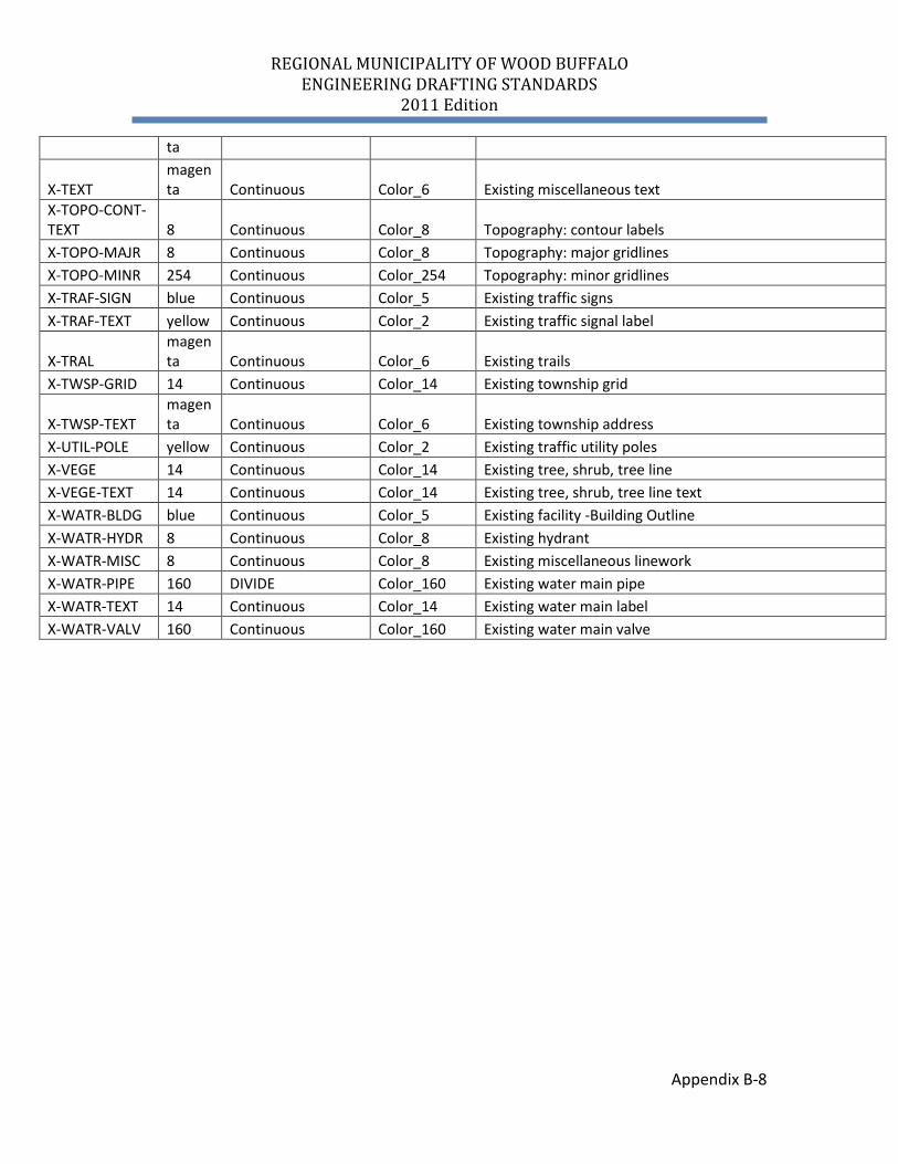
Appendix B-8
ta
X-TEXT magenta Continuous Color_6 Existing miscellaneous text
X-TOPO-CONT-TEXT 8 Continuous Color_8 Topography: contour labels X-TOPO-MAJR 8 Continuous Color_8 Topography: major gridlines X-TOPO-MINR 254 Continuous Color_254 Topography: minor gridlines X-TRAF-SIGN blue Continuous Color_5 Existing traffic signs X-TRAF-TEXT yellow Continuous Color_2 Existing traffic signal label
X-TRAL magenta Continuous Color_6 Existing trails
X-TWSP-GRID 14 Continuous Color_14 Existing township grid
X-TWSP-TEXT magenta Continuous Color_6 Existing township address
X-UTIL-POLE yellow Continuous Color_2 Existing traffic utility poles X-VEGE 14 Continuous Color_14 Existing tree, shrub, tree line X-VEGE-TEXT 14 Continuous Color_14 Existing tree, shrub, tree line text X-WATR-BLDG blue Continuous Color_5 Existing facility -Building Outline X-WATR-HYDR 8 Continuous Color_8 Existing hydrant X-WATR-MISC 8 Continuous Color_8 Existing miscellaneous linework X-WATR-PIPE 160 DIVIDE Color_160 Existing water main pipe X-WATR-TEXT 14 Continuous Color_14 Existing water main label X-WATR-VALV 160 Continuous Color_160 Existing water main valve
REGIONAL MUNICIPALITY OF WOOD BUFFALO ENGINEERING DRAFTING STANDARDS
2011 Edition
Appendix C-1
APPENDIX C
BLOCK LIBRARIES
REGIONAL MUNICIPALITY OF WOOD BUFFALO ENGINEERING DRAFTING STANDARDS
2011 Edition
Appendix D-1
APPENDIX D
STANDARD MATERIALS AND HATCH PATTERNS
REGIONAL MUNICIPALITY OF WOOD BUFFALO ENGINEERING DRAFTING STANDARDS
2011 Edition
Appendix D-2
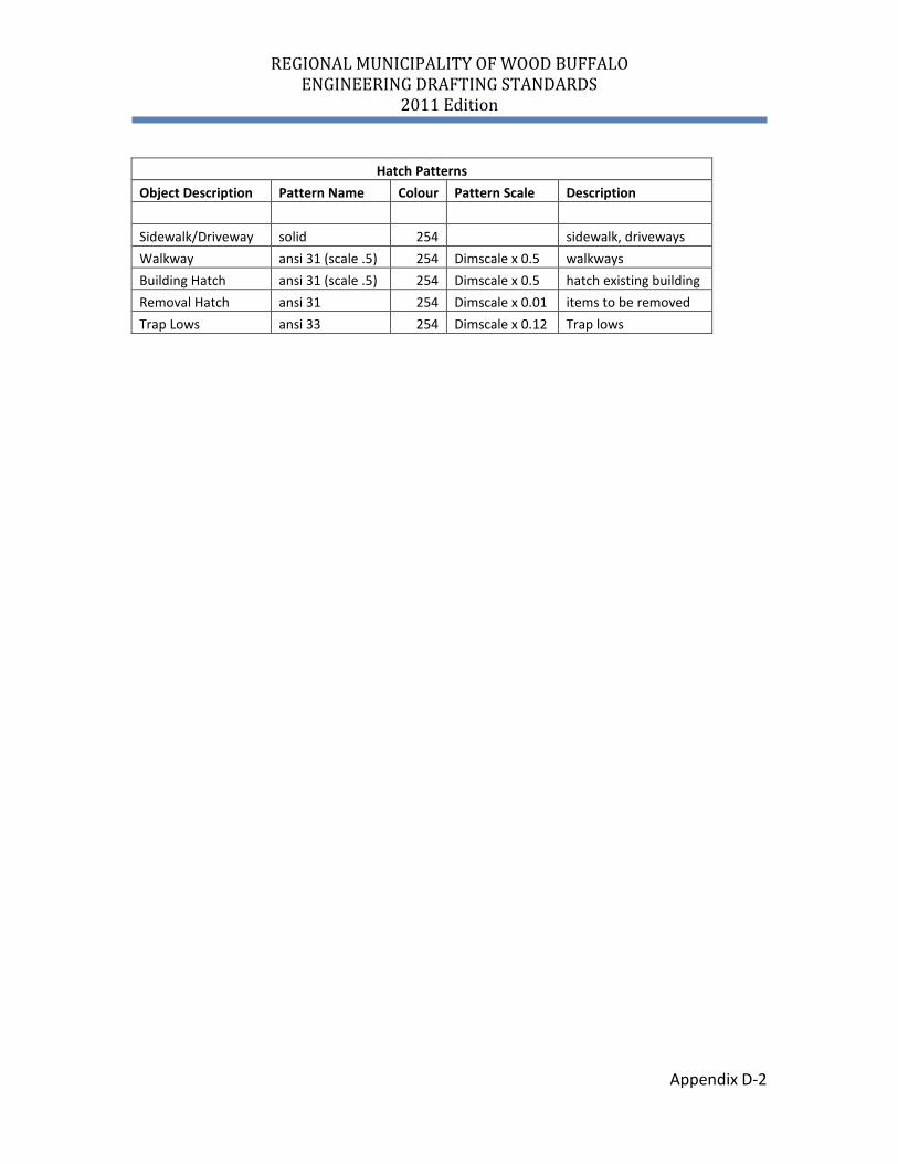
Hatch Patterns
Object Description Pattern Name Colour Pattern Scale Description Sidewalk/Driveway solid 254 sidewalk, driveways Walkway ansi 31 (scale .5) 254 Dimscale x 0.5 walkways Building Hatch ansi 31 (scale .5) 254 Dimscale x 0.5 hatch existing building Removal Hatch ansi 31 254 Dimscale x 0.01 items to be removed Trap Lows ansi 33 254 Dimscale x 0.12 Trap lows
REGIONAL MUNICIPALITY OF WOOD BUFFALO ENGINEERING DRAFTING STANDARDS
2011 Edition
Appendix E-1
APPENDIX E
SUBMISSION COMPLIANCE CHECKLIST
REGIONAL MUNICIPALITY OF WOOD BUFFALO ENGINEERING DRAFTING STANDARDS
2011 Edition
Appendix E-2
ITEM COMPLIANCE NOTES
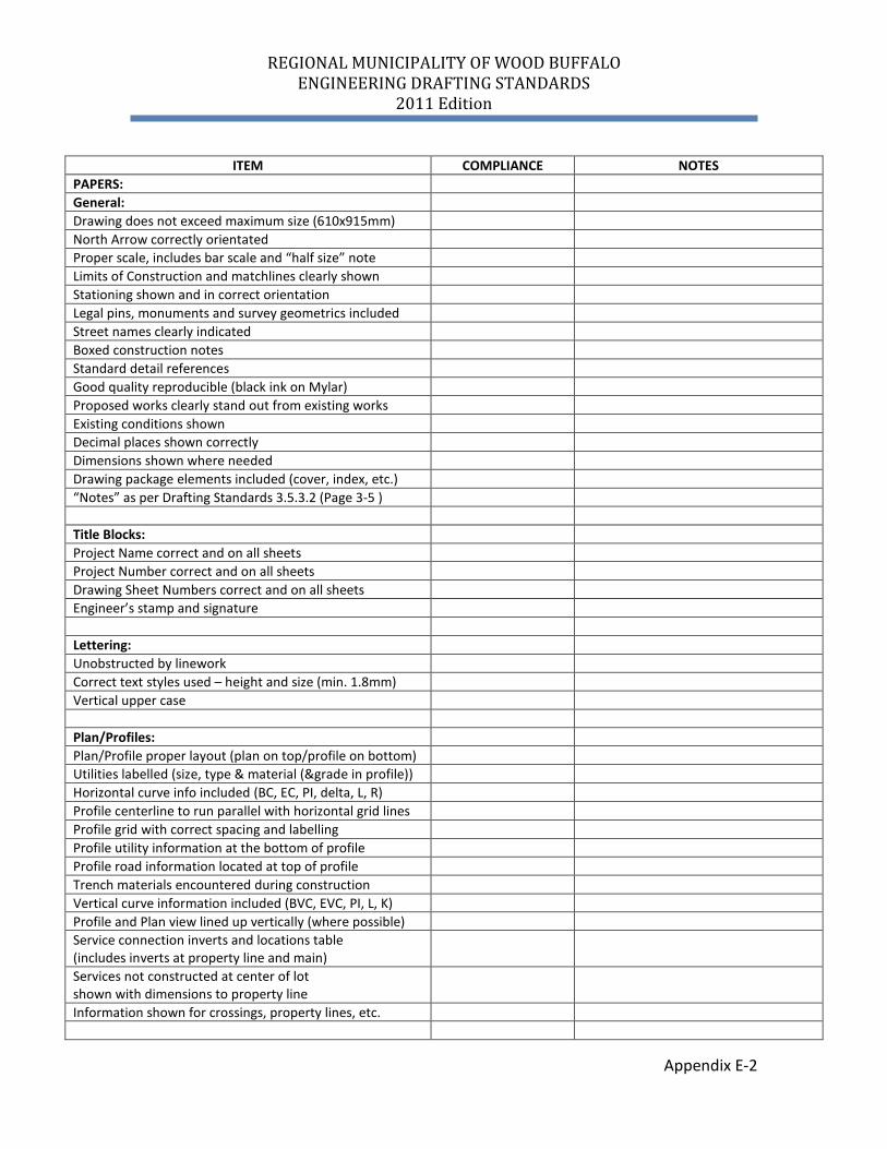
PAPERS: General: Drawing does not exceed maximum size (610x915mm) North Arrow correctly orientated Proper scale, includes bar scale and “half size” note Limits of Construction and matchlines clearly shown Stationing shown and in correct orientation Legal pins, monuments and survey geometrics included Street names clearly indicated Boxed construction notes Standard detail references Good quality reproducible (black ink on Mylar) Proposed works clearly stand out from existing works Existing conditions shown Decimal places shown correctly Dimensions shown where needed Drawing package elements included (cover, index, etc.) “Notes” as per Drafting Standards 3.5.3.2 (Page 3-5 ) Title Blocks: Project Name correct and on all sheets Project Number correct and on all sheets Drawing Sheet Numbers correct and on all sheets Engineer’s stamp and signature Lettering: Unobstructed by linework Correct text styles used – height and size (min. 1.8mm) Vertical upper case Plan/Profiles: Plan/Profile proper layout (plan on top/profile on bottom) Utilities labelled (size, type & material (&grade in profile)) Horizontal curve info included (BC, EC, PI, delta, L, R) Profile centerline to run parallel with horizontal grid lines Profile grid with correct spacing and labelling Profile utility information at the bottom of profile Profile road information located at top of profile Trench materials encountered during construction Vertical curve information included (BVC, EVC, PI, L, K) Profile and Plan view lined up vertically (where possible) Service connection inverts and locations table (includes inverts at property line and main)
Services not constructed at center of lot shown with dimensions to property line
Information shown for crossings, property lines, etc.
REGIONAL MUNICIPALITY OF WOOD BUFFALO ENGINEERING DRAFTING STANDARDS
2011 Edition
Appendix E-3
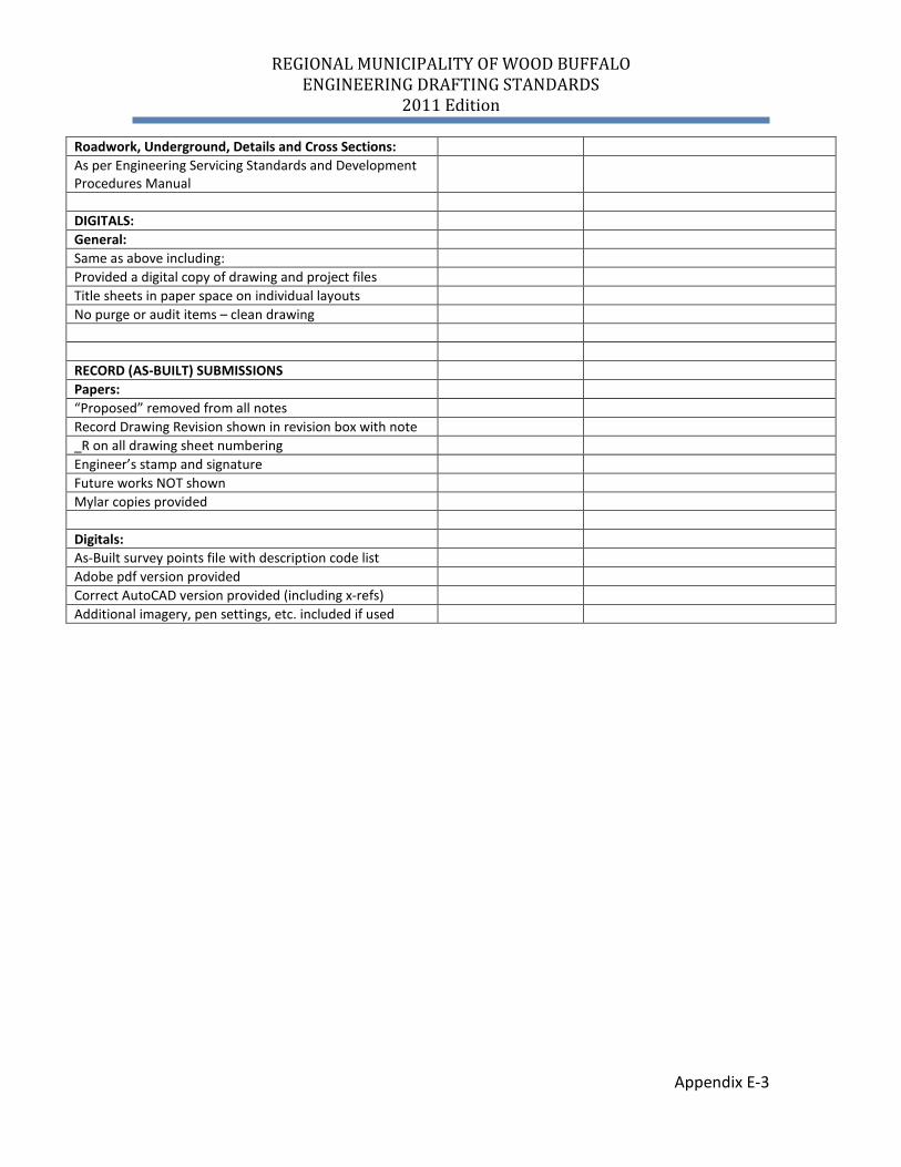
Roadwork, Underground, Details and Cross Sections: As per Engineering Servicing Standards and Development Procedures Manual
DIGITALS: General: Same as above including: Provided a digital copy of drawing and project files Title sheets in paper space on individual layouts No purge or audit items – clean drawing RECORD (AS-BUILT) SUBMISSIONS Papers: “Proposed” removed from all notes Record Drawing Revision shown in revision box with note _R on all drawing sheet numbering Engineer’s stamp and signature Future works NOT shown Mylar copies provided Digitals: As-Built survey points file with description code list Adobe pdf version provided Correct AutoCAD version provided (including x-refs) Additional imagery, pen settings, etc. included if used
REGIONAL MUNICIPALITY OF WOOD BUFFALO ENGINEERING DRAFTING STANDARDS
2011 Edition
Appendix F-1
APPENDIX F
SHEET BORDER EXAMPLES


![Triton Drafting Standards Manual[1]](https://img.pdfslide.us/doc/110x75/543ba14bafaf9f4a578b4a06/triton-drafting-standards-manual1.jpg)