Embed Size (px)
Citation preview

RISH Master 3480RISH Master 3480
Operating Manual
SYSTEM VOLTAGE CURRENT
POWER ENERGY SETUP


Section
Three Phase Touch Screen Multi-function MeterDigital
Installation & Operating Instructions
Contents
1. Introduction
2. Measurement Reading Screens
3. Programming
3.1 Password Protection
3.2 Menu selection3.2.1 System Parameter selection screen
3.2.2 Communication Parameter selection screen
3.2.1.1 System type3.2.1.2 Potential transformer Primary value3.2.1.3 Potential transformer secondary value3.2.1.4 Current transformer Primary value3.2.1.5 Current transformer Secondary value3.2.1.6 Demand integration time3.2.1.7 Auto Scrolling3.2.1.8 Low current noise cutoff3.2.1.9 Energy On RS 4853.2.1.10 Energy digit reset count
3.2.2.1 Address Setting3.2.2.2 RS 485 Baud rate
1
3.2.2.3 RS 485 Parity selection
3.1.1 Change Password
15001092 Rev.C - 8/2012
Three Phase (3W/4W)

2
3.2.4.1 Relay 1 output selection menu 3.2.4.1.1 Pulse output 3.2.4.1.1.1 Assignment of Energy to Pulse (Relay 1) 3.2.4.1.1.2 Pulse Duration Selection 3.2.4.1.1.3 Pulse Rate 3.2.4.1.2 Limit output 3.2.4.1.2.1 Assignment of Limit Output1 to Parameter 3.2.4.1.2.2 Limit Configuration 3.2.4.1.2.3 Trip point selection 3.2.4.1.2.4 Hysteresis selection 3.2.4.1.2.5 Energizing delay time 3.2.4.1.2.6 De-energizing delay time3.2.4.2 Relay 2 output selection menu3.2.4.3 Parameter setting for Analog Output-13.2.4.4 Parameter setting for Analog Output-2
3.2.4 Output Option selection screen (menu)
3.2.3.1 Resetting Parameter
8. Number of Interruption
Relay Output 10.
7. On - Hour.6. Run - Hour.
5. Phase Rotation Error screen.
9. Analog Output
3.2.5 Brightness & Contrast 4. Touch screen calibration.
Pulse output 10.1 Limit switch 10.2
RS 485 (Modbus) output User Assignable modbus Registers 11.1
11
3.2.3 Reset Parameter selection screen

15. Specification
13. Installation13.1 EMC Installation Requirements
13.2 Case Dimensions and Panel Cut-out13.3 Wiring 13.4 Auxiliary Supply
13.5 Fusing13.6 Earth / Ground Connections
14. Connection Diagrams
16. Connection for Optional Pulse output / RS 485 /Analog Ouput
12. Phaser Diagram
1. Introduction
This instrument is a panel mounted 96 x 96mm DIN Quadratic Digital metering system for themeasurement important electrical parameters like AC voltage, of AC Current, Frequency, Power, Energy(Active / Reactive / Apparent) . The instrument integrates accurate measurement Current measurements are True RMS upto 15th of technology (All Voltage & Harmonic) with 320x240 Pixels touch screen TFT LCD display.
This can be configured and programmed instrument at site for the following:
PT Primary, PT Secondary, CT Primary, CT Secondary (5A or1A) and 3 phase 3W or 3 Phase 4W system.
The front panel has a 3.5” Touch Screen through which the user can move across readings, reset the energy, the available measurement Min/Max (System Voltage and System Current) and configure the
LINE-NEUTRAL VOLTAGE
VOLTAGEMAIN
VL2
VL2
VL2
VL2
VVV
V
V0.0000.0000.000
LINE-NEUTRAL VOLTAGE
VOLTAGEMAIN
VL2
VL2
VL2
VL2
VVV
V
V0.0000.0000.000
LINE-NEUTRAL VOLTAGE
VOLTAGEMAIN
VL2
VL2
VL2
VL2
VVV
V
V0.0000.0000.000
CT SECONDARY
OK
5 AMPERE
1 AMPERE
LINE-NEUTRAL VOLTAGE
VOLTAGEMAIN
VL2
VL2
VL2
VL2
VVV
V
V0.0000.0000.000
LINE-NEUTRAL VOLTAGE
VOLTAGEMAIN
VL2
VL2
VL2
VL2
VVV
V
V0.0000.0000.000
LINE-NEUTRAL VOLTAGE
VOLTAGEMAIN
VL2
VL2
VL2
VL2
VVV
V
V0.0000.0000.000
MAIN MENU
POWER ENERGY SETUP
VOLTAGESYSTEM CURRENT
LINE-NEUTRAL VOLTAGE
VOLTAGEMAIN
VL2
VL2
VL2
VL2
VVV
V
V0.0000.0000.000
LINE-NEUTRAL VOLTAGE
VOLTAGEMAIN
VL2
VL2
VL2
VL2
VVV
V
V0.0000.0000.000
LINE-NEUTRAL VOLTAGE
VOLTAGEMAIN
VL2
VL2
VL2
VL2
VVV
V
V0.0000.0000.000
CT SECONDARY
OK
5 AMPERE
1 AMPERE
LINE-NEUTRAL VOLTAGE
VOLTAGEMAIN
VL2
VL2
VL2
VL2
VVV
V
V0.0000.0000.000
LINE-NEUTRAL VOLTAGE
VOLTAGEMAIN
VL2
VL2
VL2
VL2
VVV
V
V0.0000.0000.000
LINE-NEUTRAL VOLTAGE
VOLTAGEMAIN
VL2
VL2
VL2
VL2
VVV
V
V0.0000.0000.000
MAIN MENU
POWER ENERGY SETUP
VOLTAGESYSTEM CURRENT
product settings.
3
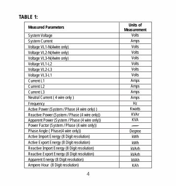
TABLE 1:
Measured Parameters
System Voltage
System Current
Frequency
Voltage VL1-N(4wire only)
Voltage VL2-N(4wire only)
Voltage VL3-N(4wire only)
Voltage VL1-L2
Voltage VL2-L3
Voltage VL3-L1
Current L1
Current L2
Current L3
Units of
Volts
Amps
Hz
Volts
Volts
Volts
Volts
Volts
Volts
Amps
Amps
Neutral Current ( 4 wire only )
Amps
Amps
Measurement
Active Import Energy (8 Digit resolution) kWh
kWhActive Export Energy (8 Digit resolution)
Active Power (System / Phase (4 wire only) )
Reactive Power (System / Phase )(4 wire only)
Apparent Power (System / Phase )(4 wire only)Power Factor (System / Phase )(4 wire only)
Phase Angle ( Phase )(4 wire only)
Kwatts
KVAr
KVA
Degree
kVArhReactive Import Energy (8 Digit resolution)
kVArhReactive Export Energy (8 Digit resolution)
kVAhApparent Energy (8 Digit resolution)
Ampere Hour (8 Digit resolution) KAh
4

Measured ParametersUnits of
KW Import Demand
KW Export Demand
Max Current Demand
Max kVA Demand
Max KW Import Demand
Max KW Export Demand
Run Hour
On Hour
Number of Interruptions
Phase Reversal Indication ( 4 wire only )
KW
Amps
KVA
KW
KW
KW
Hours
HoursCounts
Measurement
AmpsCurrent Demand
KVA Demand KVA
I1 THD
I2 THD
V1 THD*V2 THD*
V3 THD*
%
I3 THD
System Voltage THD
System Current THD
%
%%
%
%%
%
Pictorial representation of Phaser Diagram ( 4 wire only )
Pictorial representation of Voltage Waveform
Pictorial representation of Current Waveform
Pictorial representation of VA Waveform per phase ( 4 wire only )
*Note : THD Parameters are L-N in case of 3P 4W & L-L in case of 3P 3W .
5

6
2. Measurement Reading Screens
In normal operation the user is presented with one of the measurement reading screens out of several screens. These screens from particular submenu may be scrolled through one at a time in incremental order by touching the “ key” and in decremental order by touching “ key”on screen. Viewing of that any individual parameter with large reading (eg. shown
of Line to neutral Voltage L2 in sub menu 2 screen 13) is also possible by touching that
Screen 2 : System Max. Screen 1 : System Parameters(System Voltage, System
Current, System Active Power)
SUBMENU 1 : SYSTEM
KVAMin
AngleMax
KVAhPh Y
KWhPh B
%THD
Demand
LINE-NEUTRAL VOLTAGE
VOLTAGEMAIN
VL2 V
0.0000.000
LINE-NEUTRAL VOLTAGE
VOLTAGEMAIN
VL2 V
0.0000.000
LINE-NEUTRAL VOLTAGE
VOLTAGEMAIN
V
0.0000.000
SYSTEM MAX. VALUES
SYSTEMMAIN
A V239.9
5.005
LINE-NEUTRAL VOLTAGE
VOLTAGEMAIN
VL2 0.0000.000
LINE-NEUTRAL VOLTAGE
VOLTAGEMAIN
VL2 0.0000.000
LINE-NEUTRAL VOLTAGE
VOLTAGEMAIN
VL2 0.0000.000
SYSTEM RUN HOUR
SYSTEMMAIN
000001.19
hrs
Max. (System Voltage, Values
Screen 4 : Pictorial
VOLTAGEMAIN
VL2 0.000VOLTAGEMAIN
VL2 0.000VOLTAGEMAIN
VL2 0.000MAIN
Inductive
Capacitive Inductive
Capacitive
090
1800
2700
00
VL1
VL2
VL3
IL1
IL2
IL3
3
2
1
0.000
0.000
0.000
0.000
0.000
0.000
0.000
0.000
0.000
V
V
V
AA
A
V/Div
A/Div124.5
1.500-P,+Q +P,+Q
-P,-Q +P,-Q
SYSTEM
Representation of Phaser
AngleMax
KWhPh B
Demand
LINE-NEUTRAL VOLTAGE
VOLTAGEMAIN
VL2
VL2
VL2
VL2 0.0000.0000.000
LINE-NEUTRAL VOLTAGE
VOLTAGEMAIN
VL2
VL2
VL2
VL2 0.0000.0000.000
LINE-NEUTRAL VOLTAGE
VOLTAGEMAIN
VL2
VL2
VL2
VL2 0.0000.0000.000
SYSTEM PARAMETERS
SYSTEMMAIN
239.65.0013.592
A V
KW
Screen 3 : System Min. Values (System Voltage,
System Current) System Current) V
KWVBR
x1000
x1000P.F.
LINE-NEUTRAL VOLTAGE
VOLTAGEMAIN
V
0.0000.0000.000
LINE-NEUTRAL VOLTAGE
VOLTAGEMAIN
V
0.0000.0000.000
LINE-NEUTRAL VOLTAGE
VOLTAGEMAIN
V
0.0000.0000.000
SYSTEM MIN. VALUES
SYSTEMMAIN
A V239.2
4.998
LINE-NEUTRAL VOLTAGE
VOLTAGEMAIN
VL2
VL2
VL2
VL2
VVV
V
V0.0000.0000.000
LINE-NEUTRAL VOLTAGE
VOLTAGEMAIN
VL2
VL2
VL2
VL2
VVV
V
V0.0000.0000.000
LINE-NEUTRAL VOLTAGE
VOLTAGEMAIN
VL2
VL2
VL2
VL2
VVV
V
V0.0000.0000.000
SYSTEM ON HOUR
SYSTEMMAIN
000005.18
hrs
Screen 5 : System Run Hour
Screen 6 : System ON Hour
Diagram (For 4 wire only)
particular parameter.

LINE-NEUTRAL VOLTAGE
VOLTAGEMAIN
VL2
VL2
VL2
VL2
VVV
V
V0.0000.0000.000
LINE-NEUTRAL VOLTAGE
VOLTAGEMAIN
VL2
VL2
VL2
VL2
VVV
V
V0.0000.0000.000
LINE-NEUTRAL VOLTAGE
VOLTAGEMAIN
VL2
VL2
VL2
VL2
VVV
V
V0.0000.0000.000
SYSTEM INTERRUPTIONS
SYSTEMMAIN
00000012
LINE-NEUTRAL VOLTAGE
VOLTAGEMAIN
VL2
VL2
VL2
VL2
VVV
V
V0.0000.0000.000
LINE-NEUTRAL VOLTAGE
VOLTAGEMAIN
VL2
VL2
VL2
VL2
VVV
V
V0.0000.0000.000
LINE-NEUTRAL VOLTAGE
VOLTAGEMAIN
VL2
VL2
VL2
VL2
VVV
V
V0.0000.0000.000
SYSTEM FREQUENCY
SYSTEMMAIN
Hz0.000
Screen 7 : Screen 8 :
LINE-NEUTRAL VOLTAGE
VOLTAGEMAIN
VL2
VL2
VL2
VL2
VVV
V
V0.0000.0000.000
LINE-NEUTRAL VOLTAGE
VOLTAGEMAIN
VL2
VL2
VL2
VL2
VVV
V
V0.0000.0000.000
LINE-NEUTRAL VOLTAGE
VOLTAGEMAIN
VL2
VL2
VL2
VL2
VVV
V
V0.0000.0000.000
SYSTEM POWER FACTOR
SYSTEMMAIN
1.000
Screen 9 : System Interruptions System Frequency System Power Factor
LINE-NEUTRAL VOLTAGE
VOLTAGEMAIN
VL2
VL2
VL2
VL2
VVV
V
V0.0000.0000.000
LINE-NEUTRAL VOLTAGE
VOLTAGEMAIN
VL2
VL2
VL2
VL2
VVV
V
V0.0000.0000.000
LINE-NEUTRAL VOLTAGE
VOLTAGEMAIN
VL2
VL2
VL2
VL2
VVV
V
V0.0000.0000.000
SYSTEM % THD
SYSTEMMAIN
A
V
%%0.000
0.000
LINE-NEUTRAL VOLTAGE
VOLTAGEMAIN
VL2
VL2
VL2
VL2
VVV
V
V0.0000.0000.000
LINE-NEUTRAL VOLTAGE
VOLTAGEMAIN
VL2
VL2
VL2
VL2
VVV
V
V0.0000.0000.000
LINE-NEUTRAL VOLTAGE
VOLTAGEMAIN
VL2
VL2
VL2
VL2
VVV
V
V0.0000.0000.000
SYSTEM POWER
SYSTEMMAIN
kVAkVAr
kW
0.0000.0000.000
LINE-NEUTRAL VOLTAGE
VOLTAGEMAIN
VL2
VL2
VL2
VL2
VVV
V
V0.0000.0000.000
LINE-NEUTRAL VOLTAGE
VOLTAGEMAIN
VL2
VL2
VL2
VL2
VVV
V
V0.0000.0000.000
LINE-NEUTRAL VOLTAGE
VOLTAGEMAIN
VL2
VL2
VL2
VL2
VVV
V
V0.0000.0000.000
PHASE SEQUENCE
SYSTEMMAIN
L1-L2-L3CONNECTIONS ARE CORRECT
Screen 10 : System % THD
Screen 11 : System Power
Screen 12 : Phase Sequence ( 4 wire only ) Correct
Phase Sequence
LINE-NEUTRAL VOLTAGE
VOLTAGEMAIN
VL2
VL2
VL2
VL2
VVV
V
V0.0000.0000.000
LINE-NEUTRAL VOLTAGE
VOLTAGEMAIN
VL2
VL2
VL2
VL2
VVV
V
V0.0000.0000.000
LINE-NEUTRAL VOLTAGE
VOLTAGEMAIN
VL2
VL2
VL2
VL2
VVV
V
V0.0000.0000.000
PHASE SEQUENCE
SYSTEMMAIN
ERRORNOTE : WRONG PHASE SEQUENCE.
PLEASE CHECK YOUR CONNECTIONS.
Phase Sequence Error
LINE-NEUTRAL VOLTAGE
VOLTAGEMAIN
VL2
VL2
VL2
VL2
VVV
V
V0.0000.0000.000
LINE-NEUTRAL VOLTAGE
VOLTAGEMAIN
L2
L1
L3
VVV
V
V239.5239.6239.3
LINE-NEUTRAL VOLTAGELINE-NEUTRAL VOLTAGEVOLTAGEPHASE L2
239.6V
BACK
Screen 1 : 3 Line-Neutral VoltageSUBMENU 2 : VOLTAGE
(For 4 wire only)(Displayed after touching any where
Phase L2 Line-Neutral Voltage
in the L2 row shown in screen 13)
7
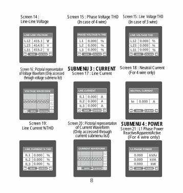
(In case of 4 wire) (In case of 3 wire)
LINE-NEUTRAL VOLTAGE
VOLTAGEMAIN
VL2
VL2
VL2
VL2 0.0000.0000.000
VOLTAGEMAIN
L23
L12
L31
0.0000.0000.000
LINE VOLTAGE THD
%
%
%
LINE-NEUTRAL VOLTAGE
VOLTAGEMAIN
VL2
VL2
VL2
VL2
VVV
V
V0.0000.0000.000
PHASE VOLTAGE % THD
VOLTAGEMAIN
L2
L1
L3
%%
%
0.0000.0000.000
LINE-NEUTRAL VOLTAGE
VOLTAGEMAIN
VL2
VL2
VL2
VL2
VVV
V
V0.0000.0000.000
LINE-LINE VOLTAGE
VOLTAGEMAIN
L23
L12
L31
VVV
V
V415.1414.9415.2
Screen 1 : 5 Phase Voltage THDScreen 1 : 4
SUBMENU 3 : CURRENT Screen 1 : 8 Neutral Current
Screen : 17 Line Current
LINE-NEUTRAL VOLTAGE
VOLTAGEMAIN
VL2
VL2
VL2
VL2
VVV
V
V0.0000.0000.000
LINE CURRENT
CURRENTMAIN
IL2
IL1
IL3
AA
A
0.0000.0000.000
LINE-NEUTRAL VOLTAGE
VOLTAGEMAIN
VL2
VL2
VL2
VL2
VVV
V
V0.0000.0000.000
LINE-NEUTRAL VOLTAGE
VOLTAGEMAIN
VL2
VL2
VL2
VL2
VVV
V
V0.0000.0000.000
LINE-NEUTRAL VOLTAGE
VOLTAGEMAIN
VL2
VL2
VL2
VL2
VVV
V
V0.0000.0000.000
NEUTRAL CURRENT
CURRENTMAIN
A0.000
Screen 16 : Pictorial representation
voltagethrough submenu list)(For 4 wire only) of (Only accessedVoltage Waveform
LINE-NEUTRAL VOLTAGE
VOLTAGEMAIN
VL2
VL2
VL2
VL2
VVV
V
V0.0000.0000.000
LINE-NEUTRAL VOLTAGE
VOLTAGEMAIN
VL2
VL2
VL2
VL2
VVV
V
V0.0000.0000.000
LINE-NEUTRAL VOLTAGE
VOLTAGEMAIN
VL2
VL2
VL2
VL2
VVV
V
V0.0000.0000.000
LINE CURRENT % THD
CURRENTMAIN
IL2
IL1
IL3
%%
%
0.0000.0000.000
LINE-NEUTRAL VOLTAGE
VOLTAGEMAIN
VL2
VL2
VL2
VL2
VVV
V
V0.0000.0000.000
LINE-NEUTRAL VOLTAGE
VOLTAGEMAIN
VL2
VL2
VL2
VL2
VVV
V
V0.0000.0000.000
LINE-NEUTRAL VOLTAGE
VOLTAGEMAIN
VL2
VL2
VL2
VL2
VVV
V
V0.0000.0000.000
L1 PHASE POWER
POWERMAIN
kVAkVAr
kW
0.0000.0000.000
Screen 19: Line Current %THD
Screen 20 : Pictorial representation
( accessed Only through of Current Waveform
current submenu list)
Screen : 21 L1 Phase PowerSUBMENU : 4 POWER
Reactive/Apparent/Active (For 4 wire only)
8
Screen 1 : Line 5 Voltage THD
LINE-NEUTRAL VOLTAGELINE-NEUTRAL VOLTAGELINE-NEUTRAL VOLTAGEVOLTAGE WAVEFORM
VOLTAGEMAIN
49.94 Hz
2.500ms/Div
62.25 V/Div
116.5Vrms
LINE-NEUTRAL VOLTAGELINE-NEUTRAL VOLTAGELINE-NEUTRAL VOLTAGECURRENT WAVEFORM
CURRENTMAIN
49.94 Hz
2.500ms/Div
30.00 A/Div
42.43Arms
42.43Arms
42.43Arms
116.5Vrms
116.5Vrms
In
Line-Line Voltage

Screen 2 : 3 L3 Phase PowerReactive/Apparent/Active
(For 4 wire only)
LINE-NEUTRAL VOLTAGE
VOLTAGEMAIN
VL2
VL2
VL2
VL2
VVV
V
V0.0000.0000.000
LINE-NEUTRAL VOLTAGE
VOLTAGEMAIN
VL2
VL2
VL2
VL2
VVV
V
V0.0000.0000.000
LINE-NEUTRAL VOLTAGE
VOLTAGEMAIN
VL2
VL2
VL2
VL2
VVV
V
V0.0000.0000.000
L2 PHASE POWER
POWERMAIN
kVAkVAr
kW
0.0000.0000.000
LINE-NEUTRAL VOLTAGE
VOLTAGEMAIN
VL2
VL2
VL2
VL2
VVV
V
V0.0000.0000.000
LINE-NEUTRAL VOLTAGE
VOLTAGEMAIN
VL2
VL2
VL2
VL2
VVV
V
V0.0000.0000.000
LINE-NEUTRAL VOLTAGE
VOLTAGEMAIN
VL2
VL2
VL2
VL2
VVV
V
V0.0000.0000.000
L3 PHASE POWER
POWERMAIN
kVAkVAr
kW
0.0000.0000.000
LINE-NEUTRAL VOLTAGE
VOLTAGEMAIN
VL2
VL2
VL2
VL2
VVV
V
V0.0000.0000.000
LINE-NEUTRAL VOLTAGE
VOLTAGEMAIN
VL2
VL2
VL2
VL2
VVV
V
V0.0000.0000.000
LINE-NEUTRAL VOLTAGE
VOLTAGEMAIN
VL2
VL2
VL2
VL2
VVV
V
V0.0000.0000.000
PHASE ANGLE
POWERMAIN
L2
L1
L3
DEG
DEG
DEG
0.0000.0000.000
Screen 24 : Phase Angle (Phase L1/L2/L3) (for 4W only)
Screen :22 L2 Phase PowerReactive/Apparent/Active
(For 4 wire only)
LINE-NEUTRAL VOLTAGE
VOLTAGEMAIN
VL2
VL2
VL2
VL2
VVV
V
V0.0000.0000.000
LINE-NEUTRAL VOLTAGE
VOLTAGEMAIN
VL2
VL2
VL2
VL2
VVV
V
V0.0000.0000.000
LINE-NEUTRAL VOLTAGE
VOLTAGEMAIN
VL2
VL2
VL2
VL2
VVV
V
V0.0000.0000.000
POWER FACTOR
POWERMAIN
L2
L1
L3
1.0001.0001.000
LINE-NEUTRAL VOLTAGE
VOLTAGEMAIN
VL2
VL2
VL2
VL2
VVV
V
V0.0000.0000.000
LINE-NEUTRAL VOLTAGE
VOLTAGEMAIN
VL2
VL2
VL2
VL2
VVV
V
V0.0000.0000.000
LINE-NEUTRAL VOLTAGE
VOLTAGEMAIN
VL2
VL2
VL2
VL2
VVV
V
V0.0000.0000.000
CURRENT DEMAND
POWERMAIN
A
A0.000
0.000
LINE-NEUTRAL VOLTAGE
VOLTAGEMAIN
VL2
VL2
VL2
VL2
VVV
V
V0.0000.0000.000
LINE-NEUTRAL VOLTAGE
VOLTAGEMAIN
VL2
VL2
VL2
VL2
VVV
V
V0.0000.0000.000
LINE-NEUTRAL VOLTAGE
VOLTAGEMAIN
VL2
VL2
VL2
VL2
VVV
V
V0.0000.0000.000
VA DEMAND
POWERMAIN
kVA
kVA0.000
0.000
Screen 25 : Power Factor (Phase L1/L2/L3) (for 4W only)
Screen 26 : Current Demand
Screen 27 : VA Demand
LINE-NEUTRAL VOLTAGE
VOLTAGEMAIN
VL2
VL2
VL2
VL2
VVV
V
V0.0000.0000.000
LINE-NEUTRAL VOLTAGE
VOLTAGEMAIN
VL2
VL2
VL2
VL2
VVV
V
V0.0000.0000.000
LINE-NEUTRAL VOLTAGE
VOLTAGEMAIN
VL2
VL2
VL2
VL2
VVV
V
V0.0000.0000.000
IMPORT ACTIVE DEMAND
POWERMAIN
kW
kW0.000
0.000
LINE-NEUTRAL VOLTAGELINE-NEUTRAL VOLTAGELINE-NEUTRAL VOLTAGEL1 PHASE WAVEFORM
POWERMAIN
116.5 V
49.94 Hz
2.500ms/Div
62.25 V/Div
42.43 A
210.4 DEG
LINE-NEUTRAL VOLTAGE
VOLTAGEMAIN
LINE-NEUTRAL VOLTAGE
VOLTAGEMAIN VOLTAGEMAIN
EXPORT ACTIVE DEMAND
POWERMAIN
kW
kW0.000
0.000
Screen 28 : Import Active Demand
Screen :29 Export Active Demand
Screen : 30 Pictorial representation
(only accessed through power submenu list) of L1 Phase Waveform (For 4 wire only)
9
Demand
MaxDemand
MaxDemand
MaxDemand
MaxDemand
Demand
Demand Demand

LINE-NEUTRAL VOLTAGE
VOLTAGEMAIN
VL2
VL2
VL2
VL2
VVV
V
V0.0000.0000.000
LINE-NEUTRAL VOLTAGE
VOLTAGEMAIN
VL2
VL2
VL2
VL2
VVV
V
V0.0000.0000.000
LINE-NEUTRAL VOLTAGE
VOLTAGEMAIN
VL2
VL2
VL2
VL2
VVV
V
V0.0000.0000.000
REACTIVE ENERGY EXPORT
ENERGYMAIN
0.0000000 kVArh
LINE-NEUTRAL VOLTAGE
VOLTAGEMAIN
VL2
VL2
VL2
VL2
VVV
V
V0.0000.0000.000
LINE-NEUTRAL VOLTAGE
VOLTAGEMAIN
VL2
VL2
VL2
VL2
VVV
V
V0.0000.0000.000
LINE-NEUTRAL VOLTAGE
VOLTAGEMAIN
VL2
VL2
VL2
VL2
VVV
V
V0.0000.0000.000
ACTIVE ENERGY IMPORT
ENERGYMAIN
0.0000000 kWh
LINE-NEUTRAL VOLTAGELINE-NEUTRAL VOLTAGELINE-NEUTRAL VOLTAGEL2 PHASE WAVEFORM
POWERMAIN
116.5 V
49.94 Hz
2.500ms/Div
62.25 V/Div
42.43 A
210.4 DEG
LINE-NEUTRAL VOLTAGELINE-NEUTRAL VOLTAGELINE-NEUTRAL VOLTAGEL3 PHASE WAVEFORM
POWERMAIN
116.5 V
49.94 Hz
2.500ms/Div
62.25 V/Div
42.43 A
210.4 DEG
L2 Phase Waveform (For 4 wire only) L3 Phase Waveform (For 4 wire only)SUBMENU : 5 ENERGY
Screen :33 Active Energy Import
Screen 34 :
LINE-NEUTRAL VOLTAGE
VOLTAGEMAIN
VL2
VL2
VL2
VL2
VVV
V
V0.0000.0000.000
LINE-NEUTRAL VOLTAGE
VOLTAGEMAIN
VL2
VL2
VL2
VL2
VVV
V
V0.0000.0000.000
LINE-NEUTRAL VOLTAGE
VOLTAGEMAIN
VL2
VL2
VL2
VL2
VVV
V
V0.0000.0000.000
ACTIVE ENERGY EXPORT
ENERGYMAIN
0.0000000 kWh
Screen 35 :
LINE-NEUTRAL VOLTAGE
VOLTAGEMAIN
VL2
VL2
VL2
VL2
VVV
V
V0.0000.0000.000
LINE-NEUTRAL VOLTAGE
VOLTAGEMAIN
VL2
VL2
VL2
VL2
VVV
V
V0.0000.0000.000
LINE-NEUTRAL VOLTAGE
VOLTAGEMAIN
VL2
VL2
VL2
VL2
VVV
V
V0.0000.0000.000
REACTIVE ENERGY IMPORT
ENERGYMAIN
0.0000000 kVArh
Active Energy Export Reactive Energy Import Reactive Energy Export Screen 36 :
LINE-NEUTRAL VOLTAGE
VOLTAGEMAIN
VL2
0.0000.0000.000
LINE-NEUTRAL VOLTAGE
VOLTAGEMAIN
VL2
0.0000.0000.000
LINE-NEUTRAL VOLTAGE
VOLTAGEMAIN
VL2
0.0000.0000.000
APPARENT ENERGY
ENERGYMAIN
0.0000000 kVAh
LINE-NEUTRAL VOLTAGE
VOLTAGEMAIN
VL2
VL2
VL2
VL2
VVV
V
V0.0000.0000.000
LINE-NEUTRAL VOLTAGE
VOLTAGEMAIN
VL2
VL2
VL2
VL2
VVV
V
V0.0000.0000.000
LINE-NEUTRAL VOLTAGE
VOLTAGEMAIN
VL2
VL2
VL2
VL2
VVV
V
V0.0000.0000.000
AMPERE HOUR
ENERGYMAIN
0.0000000 kAh
Screen :37 Screen 38 : Apparent Energy Ampere Hour
10
Screen : 31 Pictorial representation Screen : 32 Pictorial representation
(only accessed through power submenu list) (only accessed through power submenu list)

11
AMPERE HOUR
APPARENTENERGY
REACTIVE ENERGY EXPORT
REACTIVE ENERGY IMPORT
ACTIVE ENERGY EXPORT
ACTIVE ENERGY IMPORT
RESETPARAMETERS
COMMUNICATION
MAIN MENU
SYSTEM
SYSTEM TYPE
PT PRIMARY
PT SECONDARY
CT PRIMARY
CT SECONDARY
DEMAND
NOISE CUTOFF
AUTO SCROLL
(Sec 3.2.1.1)
(Sec 3.2.1.2)
(Sec 3.2.1.3)
(Sec 3.2.1.4)
(Sec 3.2.1.5)
(Sec 3.2.1.7)
Parameter Screens
INTEGRATIONTIME
LOW CURR.
CURRENTVOLTAGE
SYSTEM
Max. VOLTAGE
PHASER
RUN HOUR
AA
FREQUENCYSYSTEM
PARAMETERS
And CURRENT
Min. VOLTAGE And CURRENT
ON HOUR
No. OF INTERRUPTIONS
CT SECONDARY
DEMAND
NOISE CUTOFF
AUTO SCROLL
(Sec 3.2.1.5)
(Sec 3.2.1.7)
INTEGRATIONTIME
LOW CURR.
POWER FACTOR
SEQUENCE *
PHASE
SYSTEMPOWER
THD.VOLTAGEAND CURRENT
(Sec 3.2.2.3)
VOLTAGE % THD
Line Current
Neutral Current *
OPTIONS
(Sec 3.2.4)POWER
CHANGEPASSWORD
(Sec 3.1)ENERGY AA
AB
AB
LINE CURRENT % THD
DIAGRAM *
Line to Line VOLTAGE
Line to Neutral * VOLTAGE
NOTE: SCREENS MARKED WITH * ARE AVAILABLE
(Sec 3.2.2.3)
(Sec 3.2.2.3)
WAVEFORM VOLTAGE
WAVEFORMCURRENT
L3 PHASE WAVEFORM *
L2 PHASE WAVEFORM *
L1 PHASE WAVEFORM *
EXPORT kW DEMAND
IMPORT kW DEMAND
kVADEMAND
CURRENTDEMAND
PHASEPOWER FACTOR *
L3 PHASEPOWER *
L2 PHASEPOWER *
L1 PHASE POWER *
PHASEANGLE *
ONLY IN 4W SYSTEM (NOT IN 3 WIRE SYSTEM)

12
(Acc
. To
Tab
le 2
)(S
ec 3
.2.4
.1.2
.1)
PA
RA
ME
TE
R S
EL
EC
TIO
N
CONF
IGUR
ATIO
NSE
LEC
TIO
N(S
ec 3
.2.4
.1.2
.2)
TR
IP P
OIN
T10
% to
100%
/120
%(S
ec 3
.2.4
.1.2
.3)
HY
STE
RE
SIS
0.5%
to
50%
(Sec
3.2
.4.1
.2.4
)
EN
ER
GIZ
ING
DE
LA
Y T
IME
1s t
o 10
s(S
ec 3
.2.4
.1.2
.5)
1 s t
o 10
s(S
ec 3
.2.4
.1.2
.6)
DE-
ENER
GIZ
ING
DEL
AY T
IME
PUL
SEO
UT
PUT
(Sec
3.2
.4.1
.1)
LIM
IT
OU
TP
UT
(Sec
3.2
.4.1
.2)
PARA
MET
ER SE
LECT
ION
(Sec 3
.2.4.1
.1.1)
PULS
E RAT
E (Pu
lse D
ivisor
Rate)
1,
10, 1
00, 1
000
PULS
E RAT
E R
(Sec
3.2.4
.1.1.3
)
PULS
EDU
RATI
ON
60,10
0,200
(S
ec 3.
2.4.1.
1.2)
Rs485
ADDR
ESS
(Sec
3.2
.2.1
)
ANAL
OG O
UTPU
T 1
(Sec
3.2
.4.3
)
ANAL
OG O
UTPU
T 2
sele
ctio
n)
(Acc
. To
Tabl
e 2)
(Sec
3.2
.4.4
)
ANAL
OG O
UTPU
T 2
(A
nalog
2 pa
ram
eter
RS48
5 PAR
ITY
(Sec
3.2
.2.3
)
PT P
RIM
ARY
(Sec
3.2
.1.2
)
PT SE
COND
ARY
(Sec
3.2
.1.3
)
CT
PRIM
ARY
(Sec
3.2
.1.4
)
CT SE
COND
ARY
(Sec
3.2
.1.5
)
AUTO
SCRO
LL(S
ec 3
.2.1
.7)
NO
ISE
CU
TO
FF
(Sec
3.2
.1.8
)
LO
W C
UR
R.
RS4
85
(Sec
3.2
.2.2
)BA
UD
RAT
E
RS4
85
(Sec
3.2
.2.2
)BA
UD
RAT
E
ANAL
OG O
UTPU
T 1(A
nalog
1 pa
rame
ter
sele
ctio
n)
(Acc
. To
Tabl
e 2)
(Sec 3
.2.4.2)
RELA
Y
OUTP
UT 2
DE
MA
ND
(Sec
3.2
.1.6
)
INT
EG
RA
TIO
NT
IME
RESE
T MAX
VOLT
AGE &
CURR
ENT
RESE
T MIN
VOLT
AGE &
CURR
ENT
RESE
T RUN
-HOU
R,ON
-HOU
R
RESE
T AUX
INTE
RRUP
T COU
NTSe
lect
any
opt
ion
by
RESE
T AL
L
PA
SS
WO
RD
SYST
EM
(Sec
3.2
.1)
Se
tup
Pa
ram
ete
r S
cre
en
s
PAR
AM
ETER
S
EN
TE
R
SYST
EM
(Sec
3.2
.1)
PA
RA
ME
TE
RS
PARA
MET
ERS
COM
MUN
ICAT
ION
(Sec
3.2
.2)
PAR
AM
ET
ER
S
(Sec 3
.1)
SYST
EM T
YPE
(Sec
3.2
.1.1
)
BRIG
HTN
ESS
& C
ON
TR
AST
(Sec
3.2
.5)
CH
AN
GE
PAS
SW
OR
D(S
ec 3
.1.1
)
RES
ET
(Sec
3.2
.3)
PAR
AM
ETER
SO
PT
ION
S
OU
TP
UT
(Sec
3.2
.4)
touc
hing
on
it.
(Sec 3
.2.4.1)
RELA
Y
OUTP
UT 1
RESE
T DEM
AND P
ARAM
ETER
S RE
SET A
LL EN
ERGI
ES

3.1. Password ProtectionPassword protection can be enabled to prevent unauthorised access to set-up screens, by default password is “0000”.
Password protection is enabled by selecting any four digit number.
3. Programming
The following sections comprise step by step procedures for configuring the instrument for individual user requirements.
To access the set-up screens touch on the “ SETUP ” icon in Main Menu. This will take the User into the Password Protection Entry Stage(Section 3.1).
After touching “ SETUP” icon Password protection screen is
displayed. Screen consists of 0 to 9 digit input keypad for entering
the password very similar to any calculator in touchscreen mobile.
“Enter Password is displayed on screen at start ” so that user can enter password using displayed keypad.
Touching “ key” will display 1 in display area, similarly user can1
enter remaining 3 digits.
DEL
For deleting any digit while entering password, user can touch
SETUP
ENTER PASSWORD
1 2 3
4 5 6
7 8 9
0 BACK
DEL
ENTER
SETUP
1
“ key”.
13
1 2 3
4 5 6
7 8 9
0 BACK
DEL
ENTER

After entering the complete password user needs to confirm password
by touching “ key”. ENTER
SETUP
1234
If Entered password is correct then “Password Accepted” is displayed on screen & user will enter into setup menu.
Password confirmed.SETUP
PASSWORD ACCEPTED
If Entered password is wrong then Password “ Rejected” is displayed on screen & user need to re-enter the password
Password Incorrect.SETUP
PASSWORD REJECTED.
After wrong password is entered, user needs to touch “ key” for
trying another password. ENTER
PASSWORD
PRESS ENTER TO TRY AGAIN
14
1 2 3
4 5 6
7 8 9
0 BACK
DEL
ENTER
1 2 3
4 5 6
7 8 9
0 BACK
DEL
ENTER
1 2 3
4 5 6
7 8 9
0 BACK
DEL
ENTER
1 2 3
4 5 6
7 8 9
0 BACK
DEL
ENTER

Change Password Option is the second last option in list of “SETUP” submenu, touch anywhere in “ Change so can be accessed by a simple Password” row. In this screen user first needs to enter the current password.
3.1.1 Change Password
PASSWORD
ENTER CURRENT PASSWORD
& now user can enter the new 4 digit password.
After input of correct password,“PASSWORD ACCEPTED”is displayedPASSWORD
ENTER NEW PASSWORD
PASSWORD
PASSWORD CHANGEDAfter entering new password user needs to touch “ key” to
After confirming “PASSWORD displayed on screen,CHANGED” is which ensures successful changing of the password.
ENTER
New Password confirmed.
confirm.
3.2 Menu selection.After entering in the SUBMENU 6 - SETUP, user will be asked to enter password & after input of
correct password list of following parameters will be displayed on screen :-
3.2.1 SYSTEM PARAMETERS
3.2.2 COMMUNICATION PARAMETERS
15
1 2 3
4 5 6
7 8 9
0 BACK
DEL
ENTER
1 2 3
4 5 6
7 8 9
0 BACK
DEL
ENTER
1 2 3
4 5 6
7 8 9
0 BACK
DEL
ENTER

Touching on SYSTEM PARAMETER will open the system parameters list screen.Then these
touching the “ key” and in decremental order by touching “ key” on given touch screen.screens from particular parameter may be scrolled through one at a time in incremental order by
3.2.1 System Parameters SelectionAfter entering in the “SYSTEM PARAMETERS”, List of following parameters will be displayed :-
3.2.1.1 SYSTEM TYPE 3.2.1.2 PT PRIMARY(L-L) 3.2.1.3 PT SECONDARY(L-L) 3.2.1.4 CT PRIMARY
3.2.1.5 CT SECONDARY
3.2.1.6 DEMAND INTEGRATION TIME 3.2.1.7 AUTO SCROLL
3.2.1.8 LOW CURRENT NOISE CUTOFF
3.2.3 RESET PARAMETERS
3.2.4 OUTPUT OPTIONS
3.2.5 BRIGHTNESS & CONTRAST
3.2.1.1 System Type
LINE-NEUTRAL VOLTAGE
VL2
VL2
VL2
VL2
0.000
LINE-NEUTRAL VOLTAGE
VL2
VL2
VL2
VL2
0.000
LINE-NEUTRAL VOLTAGE
VL2
VL2
VL2
VL2
0.000
SYSTEM TYPE
3-PHASE 4 WIRE
FOR 3 PHASE STAR CONNECTED LOAD
3-PHASE 3 WIRE
FOR 3 PHASE DELTA CONNECTED LOAD
MAINMAINMAINMAINMAINMAINOK BACK
on screen. of particular type will select Touching radio button in front
This screen is used to set the system type .
Two types: 3 phase 3 wire & 3 phase 4 wire system are displayed
that type.
Touch on “ key” will confirm the system type.OK
return to previous menu. Touching the “ key” will keep the old selected setting and will BACK
16
Note : If system type is changed, relay parameter selection & analog output selection will be set to NONE.
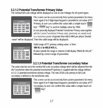
Here again 0 to 9 digit input keypad is provided to set value of PT
Primary, & user can confirm this value with a simple touch “
3.2.1.2 Primary Value Potential Transformer The nominal full scale voltage will be displayed as Line to Line Voltages for all system types.
LINE-NEUTRAL VOLTAGELINE-NEUTRAL VOLTAGELINE-NEUTRAL VOLTAGEPT PRIMARY
ENTER PT PRIMARY VALUE(L-L)
This screen can be accessed only from system parameters list menu.
key”. “ key” is used to multiply value by 1000.ENTER
In case presently displayed Potential Transformer Primary value together with the Current Transformer Primary value, previously set, would result in a maximum power of greater than 666.6 MVA per phase,”Invalid
value” will be displayed. Then the valid range will be displayed.
K
LINE-NEUTRAL VOLTAGELINE-NEUTRAL VOLTAGELINE-NEUTRAL VOLTAGEPT PRIMARY
INVALID VALUE
Valid range of PT primary setting value is from
If value outside the range is entered, It will display “INVALID VALUE”followed by correct range of parameter.
100 VL-L to 692.8 KVL-L.
3.2.1.3 Potential Transformer secondary ValueThe value must be set to the nominal full scale secondary voltage which will be obtained from the the Transformer when the potential transformer(PT)primary is supplied with the voltage defined in 3.2.1.2 potential transformer primary voltage. The ratio of full scale primary to full scale secondary is defined as the transformer ratio.
Here again 0 to 9 digit input keypad is provided to set value of PT
Secondary, & user can confirm this value with a simple touch on
This screen can be accessed only from system parameters list menu.
“ key”. ENTER
LINE-NEUTRAL VOLTAGELINE-NEUTRAL VOLTAGELINE-NEUTRAL VOLTAGEPT SECONDARY
ENTER PT SECONDARY VALUE(L-L)
17
1 2 3
4 5 6
7 8 9
DEL
ENTER
0 K BACK
1 2 3
4 5 6
7 8 9
DEL
ENTER
0 K BACK
1 2 3
4 5 6
7 8 9
DEL
ENTER
0 BACK

3.2.1.4 Current Transformer Primary Value
The nominal Full Scale Current that will be displayed as the Line currents. This screen enables the user to display the Line currents inclusive of any transformer ratios, the values displayed representthe Current in Amps.
Potential Transformer secondary ranges for various Input Voltages
110V L-L (63.5V L-N) 100 - 120V L-L (57.73V - 69.28V L-N)121 - 240V L-L (69.86V - 138.56V L-N)241 - 480V L-L (139.14V - 277.12V L-N)
230V L-L (133.0V L-N)415V L-L (239.6V L-N)
Valid range of PT value is from secondary setting 241.0 to 480.0.
If value outside the range is entered, It will display “INVALID VALUE”followed by correct range of parameter.
LINE-NEUTRAL VOLTAGELINE-NEUTRAL VOLTAGELINE-NEUTRAL VOLTAGEPT SECONDARY
INVALID VALUE
for 415 VL-L. Please refer the table bellow for different ranges.
In case presently displayed Current Transformer Primary Value together with the Potential Transformer Primary Value results in a
maximum power of greater than 666.6 MVA, “invalid value” will be displayed. Example: If primary value of PT is set as 692.8kV L-L (max value) then primary value of Current is
The “Maximum Power” restriction of 666.6 MVA refers to 120% of nominal current and
LINE-NEUTRAL VOLTAGELINE-NEUTRAL VOLTAGELINE-NEUTRAL VOLTAGECT PRIMARY
ENTER CT PRIMARY VALUE Here again 0 to 9 digit input keypad is provided to set value of CT
Primary & user can confirm this value with a simple touch on “
This screen can be accessed only from system parameters list menu.
key”. “ key” is used to multiply value by 1000.ENTER
K
120% of nominal voltage, i.e, 462.96 MVA nominal power per phase.
restricted to 1157A.
18
1 2 3
4 5 6
7 8 9
DEL
ENTER
0 BACK
1 2 3
4 5 6
7 8 9
DEL
ENTER
0 K BACK

Valid range of T primary setting value is from C 1 to 9999. If value
outside VALUE” the range is entered, It will display “INVALID followed by correct range of parameter.
LINE-NEUTRAL VOLTAGELINE-NEUTRAL VOLTAGELINE-NEUTRAL VOLTAGECT PRIMARY
INVALID VALUE
3.2.1.5 Current Transformer Secondary Value
This screen is used to set the secondary value for Current Transformer.
Touching particular option will select that option. radio button in front of
Two & options: 1 AMPERE 5 AMPERE are displayed on screen. LINE-NEUTRAL VOLTAGE
VL2
VL2VL2VVVV0.000
0.000
LINE-NEUTRAL VOLTAGE
VL2
VL2VL2VVVV0.000
0.000
LINE-NEUTRAL VOLTAGE
VL2
VL2VL2VVVV0.000
0.000
CT SECONDARY
5 AMPERE
1 AMPERE
LINE-NEUTRAL VOLTAGE
VL2
VL2VL2VVVV0.000
0.000
LINE-NEUTRAL VOLTAGE
VL2
VL2VL2VVVV0.000
0.000
LINE-NEUTRAL VOLTAGE
VL2
VL2VL2VVVV0.000
0.000
CT SECONDARY
1 AMPERE
5 AMPERE
MAINMAINMAINMAINMAINMAINOK BACK
Touch on “ key” will confirm the setting. Touching theOK
“ key” will keep the old selected setting and will return BACK
to previous menu.
3.2.1.6 Demand Integration Time
This screen is used to set the period over which current and power
readings are to be integrated.
radio button in front of particular option will select that option.
Four options: 8, 20, 15, 30 Minutes are displayed on screen. Touching
Touch on “ key” will confirm the setting.OK
LINE-NEUTRAL VOLTAGE
VL2
VL2VL2 0.0000.000
LINE-NEUTRAL VOLTAGE
VL2
VL2VL2 0.0000.000
LINE-NEUTRAL VOLTAGE
VL2
VL2VL2 0.0000.000
CT SECONDARY
5 AMPERE
1 AMPERE
LINE-NEUTRAL VOLTAGE
VL2
VL2VL2 0.0000.000
LINE-NEUTRAL VOLTAGE
VL2
VL2VL2 0.0000.000
LINE-NEUTRAL VOLTAGE
VL2
VL2VL2 0.0000.000
DEMAND INTEGRATION TIME
8 MINUTES
15 MINUTES
20 MINUTES
30 MINUTES
MAINMAINMAINMAINMAINMAINOK BACK
return to previous menu. Touching the “ key” will keep the old selected setting and will BACK
19
1 2 3
4 5 6
7 8 9
DEL
ENTER
0 K BACK

3.2.1.7 Auto Scrolling
This screen allows user to enable screen scrolling. Seven options :
POWER, ENERGY & NONE on screen. Touching radio are displayed
ALL, SYSTEM, VOLTAGE, CURRENT
button in front of particular option will select that option. Selecting
Touch on “ key” will confirm the setting.OK
particular option means, only screens which are under that submenu
will be scrolled automatically. Selecting NONE will disable Auto-Scroll.
3.2.1.8 Low Current noise cutoff.This screen allows the user to set Low noise current cutoff in mA.
screen. Touching radio button in front of particular option will
Two & options, 0 MILLI-AMPERE 30 MILLI-AMPERE are displayed on
select that option.
Touch on “ key” will confirm the setting.OK
LINE-NEUTRAL VOLTAGE
VL2
VL2VL2
LINE-NEUTRAL VOLTAGE
VL2
VL2VL2
LINE-NEUTRAL VOLTAGE
VL2
VL2VL2
CT SECONDARY
5 AMPERE
1 AMPERE
LINE-NEUTRAL VOLTAGE
VL2
VL2VL2
LINE-NEUTRAL VOLTAGE
VL2
VL2VL2
LINE-NEUTRAL VOLTAGE
VL2
VL2VL2
LOW CURRENT NOISE CUTOFF
0 MILLI-AMPERE
30 MILLI-AMPERE
MAINMAINMAINMAINMAINMAINOK BACK
and will return to previous menu. Touching the “ key” will keep the old selected setting BACK
LINE-NEUTRAL VOLTAGE
VL2
VL2
VL2 VV
V
V0.000
0.000
LINE-NEUTRAL VOLTAGE
VL2
VL2
VL2 VV
V
V0.000
0.000
LINE-NEUTRAL VOLTAGE
VL2
VL2
VL2 VV
V
V0.000
0.000
CT SECONDARY
1 AMPERE
LINE-NEUTRAL VOLTAGE
VL2
VL2
VL2 VV
V
V0.000
0.000
LINE-NEUTRAL VOLTAGE
VL2
VL2
VL2 VV
V
V0.000
0.000
LINE-NEUTRAL VOLTAGE
VL2
VL2
VL2 VV
V
V0.000
0.000
AUTO - SCROLL
ALL
VOLTAGE
POWER
NONE
SYSTEM
CURRENT
ENERGY
MAINMAINMAINMAINMAINMAINOK BACK
Touching the “ key” will keep the old selected setting and will return to previous menu. BACK
20
While in Auto-scrolling mode, touch sense for entire screen will be disabled except for the top right most corner where “A” symbol would be displayed stating that meter is in Auto-scroll mode. Touching on “A” will show two options “ON” and “OFF”. Touching on “ON” will continue auto scrolling & touching on “OFF” will stop auto-scrolling & return to normal mode.

3.2.1.9 ENERGY ON RS485.
screen. Touching radio button in front of particular option will
T hree options: WATT, KILO-WATT & MEGA-WATT are displayed on
select that option.
Touch on “ key” will confirm the setting.OK
and will return to previous menu. Touching the “ key” will keep the old selected setting BACK
This screen enable user to set energy in terms of Wh / kWh / MWh on Rs485 Output depending as per the user’s requirement .This setting is applicable for all types of energy.
LINE-NEUTRAL VOLTAGE
VL2VL2VL2
LINE-NEUTRAL VOLTAGE
VL2VL2VL2
LINE-NEUTRAL VOLTAGE
VL2VL2VL2
CT SECONDARY
5 AMPERE
1 AMPERE
LINE-NEUTRAL VOLTAGE
VL2VL2VL2
LINE-NEUTRAL VOLTAGE
VL2VL2VL2
LINE-NEUTRAL VOLTAGE
VL2VL2VL2
ENERGY ON RS485
WATT (W)
KILO-WATT (KW)
MAINMAINMAINMAINMAINMAINOK BACK
MEGA-WATT (MW)
Note : Default value is set to ‘WATT’ i.e. Energy on Modbus will be in
terms of Wh/VArh/VAh/Ah respectively.
Touching radio button in front of particular option will select that option.
If Energy on RS485 is in WATT then rollover count can be from
Touch on “ key” will confirm the setting.OK
Touching the “ key” will keep the old selected setting and will return to previous menu. BACK
3.2.1.10 ENERGY DIGIT RESET COUNT (ROLLOVER COUNT)
LINE-NEUTRAL VOLTAGE
VL2
VL2VL2
LINE-NEUTRAL VOLTAGE
VL2
VL2VL2
LINE-NEUTRAL VOLTAGE
VL2
VL2VL2
CT SECONDARY
5 AMPERE
1 AMPERE
LINE-NEUTRAL VOLTAGE
VL2
VL2VL2
LINE-NEUTRAL VOLTAGE
VL2
VL2VL2
LINE-NEUTRAL VOLTAGE
VL2
VL2VL2
ENERGY DIGIT RESET COUNT
7 DIGITS
9 DIGITS
MAINMAINMAINMAINMAINMAINOK BACK
11 DIGITS
8 DIGITS
10 DIGITS
12 DIGITS
This screen rollover to zero depending on the setting of Wh, kWh & Mwh in Energy on RS485 option.
enables the user for setting maximum energy count after which energy will
Note : Default value is set to 14 i.e energy t 14 digit count it will rollover to zero. 2) If Energy on RS485 is set to kW & energy digit reset count is set to 12, Energy screen on display will show “-------” i.e energy overflow when energy crosses the 11 digit count. 3) If Energy on RS485 is set to MW & energy digit reset count is set to 9, Energy screen on display will show “-------” i.e energy overflow when energy crosses the 8 digit count.
1) of energy digit reset count “ ” if crosses he
13 DIGITS 14 DIGITS
7 to 14 DIGITS.
If Energy on RS485 is in KILO-WATT then rollover count can be from 7 to 12 DIGITS. If Energy on RS485 is in MEGA-WATT then rollover count can be from
7 to 9 DIGITS.
21

3.2.2.1 Rs485 Address Setting
LINE-NEUTRAL VOLTAGELINE-NEUTRAL VOLTAGELINE-NEUTRAL VOLTAGERS485 ADDRESS
ENTER RS485 ADDRESS
This screen applies to the RS 485 output only. This screen allows the user to set RS485 parameter for address the instrument.
RS485 address &Here again 0 to 9 digit input keypad is provided to set
user can confirm this value with a simple touch
This screen can be accessed only from Communication Parameters List menu.
on “ key”. ENTER
The range of allowable address is 1 to 247.
If value outside VALUE” the range is entered, it will display “INVALID
followed by the correct range of parameter.
LINE-NEUTRAL VOLTAGELINE-NEUTRAL VOLTAGELINE-NEUTRAL VOLTAGERS485 ADDRESS
INVALID VALUE
3.2.2.2 RS 485 Baud RateThis screen allows the user to set Baud Rate of RS 485 port.
screen. Touching radio button in front of particular option will Four options: 2400, 4800, 9600, 19200 Bauds are displayed on
select that option.
Touch on “ key” will confirm the setting.OK
LINE-NEUTRAL VOLTAGE
VL2
VL2
VL2
VL2
V
0.0000.0000.000
LINE-NEUTRAL VOLTAGE
VL2
VL2
VL2
VL2
V
0.0000.0000.000
LINE-NEUTRAL VOLTAGE
VL2
VL2
VL2
VL2
V
0.0000.0000.000
CT SECONDARY
5 AMPERE
1 AMPERE
LINE-NEUTRAL VOLTAGE
VL2
VL2
VL2
VL2
V
0.0000.0000.000
LINE-NEUTRAL VOLTAGE
VL2
VL2
VL2
VL2
V
0.0000.0000.000
LINE-NEUTRAL VOLTAGE
VL2
VL2
VL2
VL2
V
0.0000.0000.000
RS485 BAUD RATE
2400
4800
9600
19200
MAINMAINMAINMAINMAINMAINOK BACK
and will Return to previous menu. Touching the “ key” will keep the old selected setting BACK
22
3.2.2.3 Rs485 PARITY
3.2.2.1 RS485 ADDRESS 3.2.2.2 Rs485 BAUD RATE
3.2.2 Communication Parameter Selection :After entering in the “COMMUNICATION PARAMETERS” list of following parameters
will be displayed
1 2 3
4 5 6
7 8 9
0 BACK
DEL
ENTER
1 2 3
4 5 6
7 8 9
0 BACK
DEL
ENTER
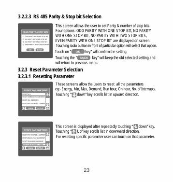
3.2.2.3 RS 485 Parity & Stop bit Selection
This screen allows the user to set Parity & number of stop bits.
Touching radio buttion in front of particular option will select that option.
Four options: ODD PARITY WITH ONE STOP BIT, NO PARITY WITH ONE STOP BIT, NO PARITY WITH TWO STOP BITS, EVEN PARITY WITH ONE STOP BIT are displayed on screen.
Touch on “ key” will confirm the setting.OK
LINE-NEUTRAL VOLTAGE
VL2
VL2
VL2
VL2
LINE-NEUTRAL VOLTAGE
VL2
VL2
VL2
VL2
LINE-NEUTRAL VOLTAGE
VL2
VL2
VL2
VL25 AMPERE
1 AMPERE
LINE-NEUTRAL VOLTAGE
VL2
VL2
VL2
VL2
LINE-NEUTRAL VOLTAGE
VL2
VL2
VL2
VL2
LINE-NEUTRAL VOLTAGE
VL2
VL2
VL2
VL2
RS485 PARITY & STOP BITS
ODD PARITY WITH ONE STOP BIT
NO PARITY WITH ONE STOP BIT
NO PARITY WITH TWO STOP BIT
EVEN PARITY WITH ONE STOP BIT
MAINMAINMAINMAINMAINMAINOK BACK
will return to previous menu. Touching the “ key” will keep the old selected setting and BACK
3.2.3.1 Resetting Parameter
These screens allow the users to reset all the parameters eg:- Energy, Min, Max, Demand, Run hour, On hour, No. of Interrupts.
3.2.3 Reset Parameter Selection
LINE-NEUTRAL VOLTAGE
VOLTAGEMAIN
VL2
VL2
VL2
VL2
VVV
V
V0.0000.0000.000
LINE-NEUTRAL VOLTAGE
VOLTAGEMAIN
VL2
VL2
VL2
VL2
VVV
V
V0.0000.0000.000
LINE-NEUTRAL VOLTAGE
VOLTAGEMAIN
VL2
VL2
VL2
VL2
VVV
V
V0.0000.0000.000
RESET PARAMETERS
SETUPMAIN
RESET ALL
RESET DEMAND PARAMETERS
RESET ALL ENERGIES
RESET MAX VOLTAGE & CURRENT
“ down” key scrolls list in upward direction. Touching
This screen is displayed after repeatedly touching “ down” key. “ ” scrolls list in ward direction. Touching Up key down
For resetting specific parameter user can touch on that parameter.
LINE-NEUTRAL VOLTAGE
VOLTAGEMAIN
VL2
VL2
VL2
VL2
VVV
V
V0.0000.0000.000
LINE-NEUTRAL VOLTAGE
VOLTAGEMAIN
VL2
VL2
VL2
VL2
VVV
V
V0.0000.0000.000
LINE-NEUTRAL VOLTAGE
VOLTAGEMAIN
VL2
VL2
VL2
VL2
VVV
V
V0.0000.0000.000
RESET PARAMETERS
SETUPMAIN
RESET MAX VOLTAGE & CURRENT
RESET MIN VOLTAGE & CURRENT
RESET RUN-HOUR, ON-HOUR
RESET AUX INTERRUPT COUNT
23

LINE-NEUTRAL VOLTAGE
VOLTAGEMAIN
VL2
VL2
VL2
VL2
VVV
V
V0.0000.0000.000
LINE-NEUTRAL VOLTAGE
VOLTAGEMAIN
VL2
VL2
VL2
VL2
VVV
V
V0.0000.0000.000
LINE-NEUTRAL VOLTAGE
VOLTAGEMAIN
VL2
VL2
VL2
VL2
VVV
V
V0.000
0.0000.000
RESET PARAMETERS
SETUPMAIN
RESET ALL
RESET DEMAND PARAMETERS
RESET MAX VOLTAGE & CURRENT
RESET ALL ENERGIES
ARE YOU SURE YOU WANT TO RESET ALL
THE STORED ENERGIES
YES NO
Touching on any parameter will display the confirmation dialog, now
a touch on “ key” will confirm the resetting of that particular YES
For example resetting All Energies will display a confirmation dialog as shown in the screen beside. User can reset other parameters in similar manner.
Parameter.
3.2.4. Output Option selection menu After entering in the “OUTPUT OPTIONS”, List of following parameters will be displayed :-
3.2.4.1 RELAY-1 3.2.4.2 RELAY-2 3.2.4.3 ANALOG-1 3.2.4. ANALOG-4 2
3.2.4.1 Relay1 output Selection menu
LINE-NEUTRAL VOLTAGE
VL2
VL2VL2
VV
0.0000.0000.000
LINE-NEUTRAL VOLTAGE
VL2
VL2VL2
VV
0.0000.0000.000
LINE-NEUTRAL VOLTAGE
VL2
VL2VL2
VV
0.0000.0000.000
CT SECONDARY
OK
5 AMPERE
1 AMPERE
LINE-NEUTRAL VOLTAGE
VL2
VL2VL2
VV
0.0000.0000.000
LINE-NEUTRAL VOLTAGE
VL2
VL2VL2
VV
0.0000.0000.000
LINE-NEUTRAL VOLTAGE
VL2
VL2VL2
VV
0.0000.0000.000
RELAY-1
PULSE OUTPUT
LIMIT OUTPUT
OUTPUT OPTIONS
This screen applies to the Relay1 Output option Selection .
screen. Touching any option will open screens of parameters Two & options : PULSE OUTPUT LIMIT OUTPUT displayed on
Touch on “ key” will take back to Output OUTPUT OPTIONS
Options screen.
related to that option.
3.2.4.1.1 Pulse output After entering in the “PULSE OUTPUT”, List of following parameters will be displayed :- 3.2.4.1.1.1 ENERGY3.2.4.1.1.2 PULSE DURATION3.2.4.1.1.3 PULSE RATEThese settings are used to assign Relay1 in Pulse output mode.
24
Touching on “ key” will move back to Reset parameters menu NO

3.2.4.1.1.1 Assignment of Energy to pulse output (Relay 1) :This screen allows the user to assign energy to pulse output (for Relay 1)
Following six options are displayed:-
Touching radio button in front of any particular option will select that option. Touch on “ key” will confirm the setting.OK
Apparent Energy Import Energy ( Active )Export Energy ( Active ) Import Energy (Reactive)Export Energy (Reactive) Ampere Hour
LINE-NEUTRAL VOLTAGE
VL2VL2
VL2
VL2
LINE-NEUTRAL VOLTAGE
VL2VL2
VL2
VL2
LINE-NEUTRAL VOLTAGE
VL2VL2
VL2
VL25 AMPERE
1 AMPERE
LINE-NEUTRAL VOLTAGE
VL2VL2
VL2
VL2
LINE-NEUTRAL VOLTAGE
VL2VL2
VL2
VL2
LINE-NEUTRAL VOLTAGE
VL2VL2
VL2
VL2
RELAY-1 ENERGY ASSIGNMENTAPPARENT ENERGY
IMPORT ENERGY(ACTIVE)EXPORT ENERGY(ACTIVE)
IMPORT ENERGY(REACTIVE)
EXPORT ENERGY(REACTIVE)
AMPERE HOUR
MAINMAINMAINMAINMAINMAINOK BACK
Touching the “ key” will keep the old selected setting and BACK
3.2.4.1.1.2 Pulse Duration Selection: This screen applies only to the Pulsed output mode of both the relays.
This screen allows the user to set Relay energisation time in milliseconds.
radio button in front of particular option will select that option.
Three options: 60, 100, 200 ms are displayed on screen. Touching
Touch on “ key” will confirm the setting.
LINE-NEUTRAL VOLTAGE
VL2
VL2VL2
LINE-NEUTRAL VOLTAGE
VL2
VL2VL2
LINE-NEUTRAL VOLTAGE
VL2
VL2VL2
CT SECONDARY
5 AMPERE
1 AMPERE
LINE-NEUTRAL VOLTAGE
VL2
VL2VL2
LINE-NEUTRAL VOLTAGE
VL2
VL2VL2
LINE-NEUTRAL VOLTAGE
VL2
VL2VL2
RELAY-1 PULSE DURATION
60 MILLI-SECONDS
100 MILLI-SECONDS
200 MILLI-SECONDS
MAINMAINMAINMAINMAINMAINOK BACK
and will return to previous menu. Touching the “ key” will keep the old selected setting
OK
BACK
3.2.4.1.1.3 Pulse RateThis screen applies only to the Pulsed output mode of both the relays.
LINE-NEUTRAL VOLTAGE
VL2
VL2VL2
VVVV0.000
0.000
LINE-NEUTRAL VOLTAGE
VL2
VL2VL2
VVVV0.000
0.000
LINE-NEUTRAL VOLTAGE
VL2
VL2VL2
VVVV0.000
0.000
CT SECONDARY
5 AMPERE
1 AMPERE
LINE-NEUTRAL VOLTAGE
VL2
VL2VL2
VVVV0.000
0.000
LINE-NEUTRAL VOLTAGE
VL2
VL2VL2
VVVV0.000
0.000
LINE-NEUTRAL VOLTAGE
VL2
VL2VL2
VVVV0.000
0.000
RELAY-1 PULSE RATE DIVISOR
1
10
100
1000
MAINMAINMAINMAINMAINMAINOK BACK
The screen allows user to set the energy pulse rate divisor. Divisor values can be selected through 1,10, 100,1000.Touching radio button in front of particular value will select that value.
will return to previous menu.
Touch on “ key” will confirm the setting.OK
Touching the “ key” will keep the old selected setting BACK
and will return to previous menu.
25

3.2.4.1.2 Limit output
This screen is for Limit output mode selection. It allows the user to set Limit output corresponding measured value. After entering in Limit Output first time(was disabled previously), only “PARAMETER:” is displayed on screen. Now a simple touch on “PARAMETER:” will open list of parameters, Refer Table 2 “Parameter for Analog & Limit output” for assignment.Now after assignment of any parameter, list of following setting parameters will be displayed:-
3.2.4.1.2.1 PARAMETER
3.2.4.1.2.2 CONFIG
3.2.4.1.2.3 TRIP POINT
3.2.4.1.2.4 HYSTERESIS POINT
3.2.4.1.2.5 ENERGIZING DELAY3.2.4.1.2.6 DE-ENERGIZING DELAY
3.2.4.1.1.2.2 Limit1 Configuration selectThis screen is used to set the Limit1 Configuration, four different types of configuration can be selected
HIGH ALARM & ENERGIZED RELAYHIGH ALARM & DE-ENERGIZED RELAYLOW ALARM & ENERGIZED RELAYLOW ALARM & DE-ENERGIZED RELAY(For detail refer to section 9.2)
Touching radio button in front of particular type will select that type.
Touch on “ key” will confirm the setting.
Touching the “ key” will keep the old selected setting and will return to previous menu.
OK
BACK
LINE-NEUTRAL VOLTAGE
VL2
VL2
VL2
VL2
LINE-NEUTRAL VOLTAGE
VL2
VL2
VL2
VL2
LINE-NEUTRAL VOLTAGE
VL2
VL2
VL2
VL2
CT SECONDARY
5 AMPERE
1 AMPERE
LINE-NEUTRAL VOLTAGE
VL2
VL2
VL2
VL2
LINE-NEUTRAL VOLTAGE
VL2
VL2
VL2
VL2
LINE-NEUTRAL VOLTAGE
VL2
VL2
VL2
VL2
RELAY-1 CONFIGURATION
HIGH ALARM & ENERGIZED RELAY
HIGH ALARM & DE-ENERGIZED RELAY
LOW ALARM & ENERGIZED RELAY
LOW ALARM & DE-ENERGIZED RELAY
MAINMAINMAINMAINMAINMAINOK BACK
26
3.2.4.1.2.1 Limit Parameter selection This option allows the user to set Relay\-1 limit to corresponding measured parameter. A simple touch on “PARAMETER” row will open screen having list of parameters. (Refer Table 2 “Parameters for Analog & limit output”) Touch on “ key” will confirm the setting.
Touching the “ key” will keep the old selected setting and will return to previous menu.
OK
BACK

3.2.4.1.2.3 Trip point selection This screen applies to the Trip point selection.
This screen allows the user to set Trip point for instrument in %.
LINE-NEUTRAL VOLTAGELINE-NEUTRAL VOLTAGELINE-NEUTRAL VOLTAGERELAY-1 TRIP POINT
ENTER TRIP POINT IN % Here a 0 to 9 digit input keypad is provided to set value of Trip Point,
& user can confirm this value with a simple touch on “ key.”
This screen can be accessed only from Limit Output settings list menu.
“ key” is used to go back to Limit Output list menu.
ENTER
BACK
The allowable range is from 10% to 120% for High Alarm & is from
10% to 100% for Low Alarm.LINE-NEUTRAL VOLTAGELINE-NEUTRAL VOLTAGELINE-NEUTRAL VOLTAGERELAY-1 TRIP POINT
INVALID VALUE If value outside this range is entered, it will display “INVALID VALUE”followed by correct range of parameter.
3.2.4.1.2.4 Hysteresis selectionThis screen applies to the Hysteresis selection.
LINE-NEUTRAL VOLTAGELINE-NEUTRAL VOLTAGELINE-NEUTRAL VOLTAGERELAY-1 HYSTERESIS
SET HYSTERESIS IN %
This screen allows the user to set Hysteresis in % for relay1.
Here a 0 to 9 digit input keypad is provided to set value of Hysteresis,
& user can confirm this value with a simple touch on “ key”.
This screen can be accessed only from list menu.Limit Output settings
“ key” is used to go back to Limit Output list menu.
ENTER
BACK
27
1 2 3
4 5 6
7 8 9
0 BACK
DEL
ENTER
1 2 3
4 5 6
7 8 9
0 BACK
DEL
ENTER
1 2 3
4 5 6
7 8 9
DEL
ENTER
0 K BACK.

The allowable .range is 0.5% to 50 % of Trip point LINE-NEUTRAL VOLTAGELINE-NEUTRAL VOLTAGELINE-NEUTRAL VOLTAGERELAY-1 HYSTERESIS
INVALID VALUE
If value outside this range is entered, it will display “INVALID VALUE”followed by correct range of parameter.
3.2.4.1.2.5 Energizing Delay time.This screen allows the user to set Energizing Delay time for Relay 1 Limit Assigned Parameters .
LINE-NEUTRAL VOLTAGELINE-NEUTRAL VOLTAGELINE-NEUTRAL VOLTAGERELAY-1 ENERGIZING DELAY
ENTER ENERGIZING DELAY IN SEC
Here a 0 to 9 digit input keypad is provided to set value of Delay, &
user can confirm this value with a simple touch on “ key.”
This screen can be accessed only from Limit Output settings list menu.
“ key” is used to go back to Limit Output list menu.
ENTER
BACK
The allowable range is from 1 to 10 sec. If value outside this range is entered, it will display “INVALID VALUE”followed by correct range of parameter.
LINE-NEUTRAL VOLTAGELINE-NEUTRAL VOLTAGELINE-NEUTRAL VOLTAGERELAY-1 ENERGIZING DELAY
VALID RANGE IS : 1 - 10 Secs
28
1 2 3
4 5 6
7 8 9
DEL
ENTER
0 K BACK.
1 2 3
4 5 6
7 8 9
0 BACK
DEL
ENTER
1 2 3
4 5 6
7 8 9
0 BACK
DEL
ENTER
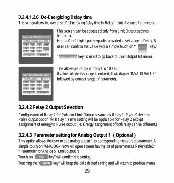
3.2.4.1.2.6 De-Energizing Delay timeThis screen allows the user to set De-Energizing Delay time for Relay 1 Limit Assigned Parameters .
LINE-NEUTRAL VOLTAGELINE-NEUTRAL VOLTAGELINE-NEUTRAL VOLTAGERELAY-1 DE-ENERGIZING DELAY
ENTER DE-ENERGIZING DELAY IN SEC Here a 0 to 9 digit input keypad is provided to set value of Delay, &
user can confirm this value with a simple touch on “ key.”
This screen can be accessed only from Limit Output settings list menu.
“ key” is used to go back to Limit Output list menu.
ENTER
BACK
The allowable range is from 1 to 10 sec. If value outside this range is entered, It will display “INVALID VALUE”followed by correct range of parameter.
LINE-NEUTRAL VOLTAGELINE-NEUTRAL VOLTAGELINE-NEUTRAL VOLTAGE
VALID RANGE IS : 1 - 10 Secs
RELAY-1 DE-ENERGIZING DELAY
3.2.4.2 Relay 2 Output Selection
Configuration of Relay 2 for Pulse or Limit Output is same as Relay 1. If you Select the Pulse output option for Relay 1 same setting will be applicable for Relay 2 except assignment of energy to Pulse output (i.e. Energy assignment of both relay can be different.)
3.2.4.3 Parameter setting for Analog Output 1 ( Optional )This option allows the user to set analog output 1 to corresponding measured parameter. simple touch on “ANALOG-1”row will open screen having list of parameters.( Refer table2 “ Parameter for Analog & Limit output ”)
A
29
Touch on “ key” will confirm the setting.
Touching the “ key” will keep the old selected setting and will return to previous menu.
OK
BACK
1 2 3
4 5 6
7 8 9
0 BACK
DEL
ENTER
1 2 3
4 5 6
7 8 9
0 BACK
DEL
ENTER

Touch on “ key” will confirm the setting.
Touching the “ key” will keep the old selected setting and will return to previous menu.
OK
BACK
LINE-NEUTRAL VOLTAGE
VOLTAGEMAIN
VL2
VL2
VL2
VL2
VVV
V
V0.0000.0000.000
LINE-NEUTRAL VOLTAGE
VOLTAGEMAIN
VL2
VL2
VL2
VL2
VVV
V
V0.0000.0000.000
LINE-NEUTRAL VOLTAGE
VOLTAGEMAIN
VL2
VL2
VL2
VL2
VVV
V
V0.0000.0000.000
CT SECONDARY
OK
5 AMPERE
1 AMPERE
LINE-NEUTRAL VOLTAGE
VOLTAGEMAIN
VL2
VL2
VL2
VL2
VVV
V
V0.0000.0000.000
LINE-NEUTRAL VOLTAGE
VOLTAGEMAIN
VL2
VL2
VL2
VL2
VVV
V
V0.0000.0000.000
LINE-NEUTRAL VOLTAGE
VOLTAGEMAIN
VL2
VL2
VL2
VVV
V
V0.0000.0000.000
IMPORTANT. Performing touch screen calibration.Press & hold the center of the filled circle
Touch screen to continue.
3.2.4.4 Analog Output 2 ( Optional )Parameter setting for This option allows the user to set analog output to corresponding measured parameter. simple touch on “ANALOG-2”row will open screen having list of parameters.( Refer table2 “ Parameter for Analog & Limit output ”)
2 A
3.2.5 Brightness & Contrast
The brightness & contrast of the TFT LCD screen can be varied by OK
Touching the DEFAULT key will set brightness and contrast as per factory settings. Touching the BACK key will move back to the setup menu without making any changes.
the user by sliding the sliders. Touching the “ key” will confirm the current brightness contrast setting.
LINE-NEUTRAL VOLTAGE
VOLTAGEMAIN
VL2
VL2
VL2
VL2
VVV
V
V0.000
0.000
LINE-NEUTRAL VOLTAGE
VOLTAGEMAIN
VL2
VL2
VL2
VL2
VVV
V
V0.000
0.000VOLTAGEMAIN
BRIGHTNESS & CONTRAST
BACKDEFAULT OK
DEFAULTCONTRAST
BRIGHTNESS
30
4 Touch screen calibration This is able to perform calibration to ensure the proper operation of the units touch screen functionalities. The calibration procedure will correct the problem of out of tolerance touch screen malfunction. Note that errors corrected by this calibration procedure are specific only to touch screen operation.
instrument
For starting touch screen calibration, touch the screen any where for 1 sec at system reset. After that touch screen calibration will start & the message shown besides will be displayed. Touch the screen to continue.
LINE-NEUTRAL VOLTAGE
VOLTAGEMAIN
VL2
VL2
VL2
VL2
VVV
V
V0.0000.0000.000
LINE-NEUTRAL VOLTAGE
VOLTAGEMAIN
VL2
VL2
VL2
VL2
VVV
V
V0.0000.0000.000
LINE-NEUTRAL VOLTAGE
VOLTAGEMAIN
VL2
VL2
VL2
VL2
VVV
V
V0.0000.0000.000
CT SECONDARY
OK
5 AMPERE
1 AMPERE
LINE-NEUTRAL VOLTAGE
VOLTAGEMAIN
VL2
VL2
VL2
VL2
VVV
V
V0.0000.0000.000
LINE-NEUTRAL VOLTAGE
VOLTAGEMAIN
VL2
VL2
VL2
VL2
VVV
V
V0.0000.0000.000
LINE-NEUTRAL VOLTAGE
VOLTAGEMAIN
VL2
VL2
VL2
VVV
V
V0.0000.0000.000
Press on the filled circle
LINE-NEUTRAL VOLTAGE
VOLTAGEMAIN
VL2
VL2
VL2
VL2
VVV
V
V0.0000.0000.000
LINE-NEUTRAL VOLTAGE
VOLTAGEMAIN
VL2
VL2
VL2
VL2
VVV
V
V0.0000.0000.000
LINE-NEUTRAL VOLTAGE
VOLTAGEMAIN
VL2
VL2
VL2
VL2
VVV
V
V0.0000.0000.000
CT SECONDARY
OK
5 AMPERE
1 AMPERE
LINE-NEUTRAL VOLTAGE
VOLTAGEMAIN
VL2
VL2
VL2
VL2
VVV
V
V0.0000.0000.000
LINE-NEUTRAL VOLTAGE
VOLTAGEMAIN
VL2
VL2
VL2
VL2
VVV
V
V0.0000.0000.000
LINE-NEUTRAL VOLTAGE
VOLTAGEMAIN
VL2
VL2
VL2
VVV
V
V0.0000.0000.000
Hold the filled circle
LINE-NEUTRAL VOLTAGE
VOLTAGEMAIN
VL2
VL2
VL2
VL2
VVV
V
V0.0000.0000.000
LINE-NEUTRAL VOLTAGE
VOLTAGEMAIN
VL2
VL2
VL2
VL2
VVV
V
V0.0000.0000.000
LINE-NEUTRAL VOLTAGE
VOLTAGEMAIN
VL2
VL2
VL2
VL2
VVV
V
V0.0000.0000.000
CT SECONDARY
OK
5 AMPERE
1 AMPERE
LINE-NEUTRAL VOLTAGE
VOLTAGEMAIN
VL2
VL2
VL2
VL2
VVV
V
V0.0000.0000.000
LINE-NEUTRAL VOLTAGE
VOLTAGEMAIN
VL2
VL2
VL2
VL2
VVV
V
V0.0000.0000.000
LINE-NEUTRAL VOLTAGE
VOLTAGEMAIN
VL2
VL2
VL2
VVV
V
V0.0000.0000.000
Release the filled circle
LINE-NEUTRAL VOLTAGE
VOLTAGEMAIN
VL2
VL2
VL2
VL2
VVV
V
V0.0000.0000.000
LINE-NEUTRAL VOLTAGE
VOLTAGEMAIN
VL2
VL2
VL2
VL2
VVV
V
V0.0000.0000.000
LINE-NEUTRAL VOLTAGE
VOLTAGEMAIN
VL2
VL2
VL2
VL2
VVV
V
V0.0000.0000.000
CT SECONDARY
OK
5 AMPERE
1 AMPERE
LINE-NEUTRAL VOLTAGE
VOLTAGEMAIN
VL2
VL2
VL2
VL2
VVV
V
V0.0000.0000.000
LINE-NEUTRAL VOLTAGE
VOLTAGEMAIN
VL2
VL2
VL2
VL2
VVV
V
V0.0000.0000.000
LINE-NEUTRAL VOLTAGE
VOLTAGEMAIN
VL2
VL2
VL2
VVV
V
V0.0000.0000.000
Hold the filled circle
LINE-NEUTRAL VOLTAGE
VOLTAGEMAIN
VL2
VL2
VL2
VL2
VVV
V
V0.0000.0000.000
LINE-NEUTRAL VOLTAGE
VOLTAGEMAIN
VL2
VL2
VL2
VL2
VVV
V
V0.0000.0000.000
LINE-NEUTRAL VOLTAGE
VOLTAGEMAIN
VL2
VL2
VL2
VL2
VVV
V
V0.0000.0000.000
CT SECONDARY
OK
5 AMPERE
1 AMPERE
LINE-NEUTRAL VOLTAGE
VOLTAGEMAIN
VL2
VL2
VL2
VL2
VVV
V
V0.0000.0000.000
LINE-NEUTRAL VOLTAGE
VOLTAGEMAIN
VL2
VL2
VL2
VL2
VVV
V
V0.0000.0000.000
LINE-NEUTRAL VOLTAGE
VOLTAGEMAIN
VL2
VL2
VL2
VVV
V
V0.0000.0000.000
Press on the filled circle
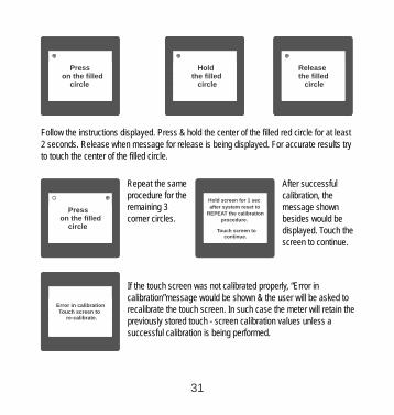
Follow the instructions displayed. Press & hold the center of the filled red circle for at least 2 seconds. Release when message for release is being displayed. For accurate results try to touch the center of the filled circle.
Repeat the same procedure for the remaining 3 corner circles.
LINE-NEUTRAL VOLTAGE
VOLTAGEMAIN
VL2
VL2
VL2
VL2
VVV
V
V0.0000.0000.000
LINE-NEUTRAL VOLTAGE
VOLTAGEMAIN
VL2
VL2
VL2
VL2
VVV
V
V0.0000.0000.000
LINE-NEUTRAL VOLTAGE
VOLTAGEMAIN
VL2
VL2
VL2
VL2
VVV
V
V0.0000.0000.000
CT SECONDARY
OK
5 AMPERE
1 AMPERE
LINE-NEUTRAL VOLTAGE
VOLTAGEMAIN
VL2
VL2
VL2
VL2
VVV
V
V0.0000.0000.000
LINE-NEUTRAL VOLTAGE
VOLTAGEMAIN
VL2
VL2
VL2
VL2
VVV
V
V0.0000.0000.000
LINE-NEUTRAL VOLTAGE
VOLTAGEMAIN
VL2
VL2
VL2
VVV
V
V0.0000.0000.000
Hold screen for 1 sec
after system reset to
REPEAT the calibration
procedure.
Touch screen to continue.
After successful calibration, the message shown besides would be displayed. Touch the screen to continue.
LINE-NEUTRAL VOLTAGE
VOLTAGEMAIN
VL2
VL2
VL2
VL2
VVV
V
V0.0000.0000.000
LINE-NEUTRAL VOLTAGE
VOLTAGEMAIN
VL2
VL2
VL2
VL2
VVV
V
V0.0000.0000.000
LINE-NEUTRAL VOLTAGE
VOLTAGEMAIN
VL2
VL2
VL2
VL2
VVV
V
V0.0000.0000.000
CT SECONDARY
OK
5 AMPERE
1 AMPERE
LINE-NEUTRAL VOLTAGE
VOLTAGEMAIN
VL2
VL2
VL2
VL2
VVV
V
V0.0000.0000.000
LINE-NEUTRAL VOLTAGE
VOLTAGEMAIN
VL2
VL2
VL2
VL2
VVV
V
V0.0000.0000.000
LINE-NEUTRAL VOLTAGE
VOLTAGEMAIN
VL2
VL2
VL2
VVV
V
V0.0000.0000.000
Error in calibrationTouch screen to re-calibrate.
If the touch screen was not calibrated properly, “Error in calibration”message would be shown & the user will be asked to recalibrate the touch screen. In such case the meter will retain the previously stored touch - screen calibration values unless a successful calibration is being performed.
31

C hase sequenceorrect PThis Screen indicates the phase sequence connected to
meter is correct. If phase sequence is wrong this screen is useful
to get correct phase sequence by interchanging connection &
verifying it with screen.
VYB
VRYKVAr
Sys
V
A
KVAMin
KWVBR
AngleMax
x1000
KVArh
x1000
x1000
IN
Ph R
HzKVAhPh Y
P.F.KWhPh B
KAh
%THD
Demand
LINE-NEUTRAL VOLTAGE
VOLTAGEMAIN
VL2
VL2
VL2
VL2
VVV
V
V0.0000.0000.000
LINE-NEUTRAL VOLTAGE
VOLTAGEMAIN
VL2
VL2
VL2
VL2
VVV
V
V0.0000.0000.000
LINE-NEUTRAL VOLTAGE
VOLTAGEMAIN
VL2
VL2
VL2
VL2
VVV
V
V0.0000.0000.000
PHASE SEQUENCE
SYSTEMMAIN
L1-L2-L3
CONNECTIONS ARE CORRECT
This Screen indicates that either of the phases or all three phases (Voltages) are absent.
VYB
VRYKVAr
Sys
V
A
KVAMin
KWVBR
AngleMax
x1000
KVArh
x1000
x1000
IN
Ph R
HzKVAhPh Y
P.F.KWhPh B
KAh
%THD
Demand
LINE-NEUTRAL VOLTAGE
VOLTAGEMAIN
VL2
VL2
VL2
VL2
VVV
V
V0.0000.0000.000
LINE-NEUTRAL VOLTAGE
VOLTAGEMAIN
VL2
VL2
VL2
VL2
VVV
V
V0.0000.0000.000
LINE-NEUTRAL VOLTAGE
VOLTAGEMAIN
VL2
VL2
VL2
VL2
VVV
V
V0.0000.0000.000
PHASE SEQUENCE
SYSTEMMAIN
INPUT ABSENT PLEASE CHECK YOUR CONNECTIONS.
6 Run Hour . This Screen shows the total no. of hours the load is connected Even if the Auxiliary supply is interrupted count of Run hour will be
maintained in internal memory & displayed in the format “hours. min”.
For example if Displayed count is 000001.19 hrs it indicates
1 hors & 19 minutes.
After 999999.59 run hours display will restart from zero.
To reset run hour manually see section Resetting Parameter 3.2.3.1
LINE-NEUTRAL VOLTAGE
VOLTAGEMAIN
VL2
VL2
VL2
VL2
VVV
V
V0.0000.0000.000
LINE-NEUTRAL VOLTAGE
VOLTAGEMAIN
VL2
VL2
VL2
VL2
VVV
V
V0.0000.0000.000
LINE-NEUTRAL VOLTAGE
VOLTAGEMAIN
VL2
VL2
VL2
VL2
VVV
V
V0.0000.0000.000
SYSTEM RUN HOUR
SYSTEMMAIN
000001.19
hrs
32
LINE-NEUTRAL VOLTAGE
VOLTAGEMAIN
VL2
VL2
VL2
VL2
VVV
V
V0.0000.0000.000
LINE-NEUTRAL VOLTAGE
VOLTAGEMAIN
VL2
VL2
VL2
VL2
VVV
V
V0.0000.0000.000
LINE-NEUTRAL VOLTAGE
VOLTAGEMAIN
VL2
VL2
VL2
VL2
VVV
V
V0.0000.0000.000
PHASE SEQUENCE
SYSTEMMAIN
ERROR NOTE : WRONG PHASE SEQUENCE.
PLEASE CHECK YOUR CONNECTIONS.
5. Phase Rotation Error screen
Meter shows phase rotation error if the phase sequenceR-Y-B (L1-L2-L3) is not maintained This screen indicates that Phase sequence is incorrect. User must check this screen in order to get correct readings When meter is connected.

7 Hour . On
This Screen shows the total no. of hours the Axillary Supply is ON.Even if the Auxiliary supply is interrupted count of On hour will be
maintained in internal memory & displayed in the format “hours. min”.
For example if Displayed count is 000005.18 hrs it indicates 15 hours & 18 minutes.After 999999.59 On hours display will restart from zero.To reset On hour manually see section Resetting Parameter 3.2.3.1
LINE-NEUTRAL VOLTAGE
VOLTAGEMAIN
VL2
VL2
VL2
VL2
VVV
V
V0.0000.0000.000
LINE-NEUTRAL VOLTAGE
VOLTAGEMAIN
VL2
VL2
VL2
VL2
VVV
V
V0.0000.0000.000
LINE-NEUTRAL VOLTAGE
VOLTAGEMAIN
VL2
VL2
VL2
VL2
VVV
V
V0.0000.0000.000
SYSTEM ON HOUR
SYSTEMMAIN
000005.18
hrs
8 Interruption. Number of
This Screen Displays the total no. of times the Axillary Supply was Interrupted. Even if the Auxiliary supply is interrupted count will be
To reset No of Interruption manually see section Resetting Parameter 3.2.3.1
maintained in internal memoryLINE-NEUTRAL VOLTAGE
VOLTAGEMAIN
VL2
VL2
VL2
VL2
VVV
V
V0.0000.0000.000
LINE-NEUTRAL VOLTAGE
VOLTAGEMAIN
VL2
VL2
VL2
VL2
VVV
V
V0.0000.0000.000
LINE-NEUTRAL VOLTAGE
VOLTAGEMAIN
VL2
VL2
VL2
VL2
VVV
V
V0.0000.0000.000
SYSTEM INTERRUPTIONS
SYSTEMMAIN
00000012
9. Analog Output ( optional ) :
This module provides two d.c. isolated outputs .There are two output options
1) Two 0 - 1mA outputs , internally powered .2) Two 4 - 20mA outputs , internally powered .
The 0 -1mA output module has an 0V return on each end of the 4 way connector ( Please refer section 15 for connection details )
On both modules the output signals are present on pins A1(Analog Output 1) & A2 (Analog Output 2)
33

Diagram 1 : ( 4 -20 mA )
These outputs can be individually assigned to represent any one of the measured and displayed Parameters.
All settlings are user configurable via the user interface screen. See Analog o/p selection ( section 3.2.4.3 & section 3.2.4.4 ) for details .
* Note : Refer diagrams 1 & 2
00 (12 mA)
181 (4 mA)0
180 (20 mA)0
90 (16 mA)0
270 (8 mA)0
34
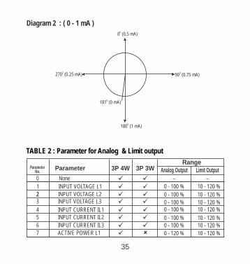
Diagram 2 : ( 0 - 1 mA )0
0 (0.5 mA)
181 (0 mA)0
180 (1 mA)0
90 (0.75 mA)0270 (0.25 mA)
0
TABLE 2 : Parameter for Analog & Limit output
INPUT VOLTAGE L1
Parameter Parameter
0
1
2 INPUT VOLTAGE L223 INPUT VOLTAGE L3
None
4 INPUT CURRENT IL1
3P 4W 3P 3WRange
0 - 100 %
0 - 100 %
0 - 100 %0 - 100 %
5 INPUT CURRENT IL2
6 INPUT CURRENT IL30 - 100 %0 - 100 %
0 - 120 %
üüü
üüü
ü üü üü üü ü
7 ACTIVE POWER L1 û ü
– No. Analog Output Limit Output
35
–
10 - 120 %
10 - 120 %
10 - 120 %10 - 120 %
10 - 120 %10 - 120 %
10 - 120 %

0 - 120 %8 ACTIVE POWER L2
0 - 120 %ü û
9 ACTIVE POWER L3
0 - 120 %ü û
10 APPARENT POWER L1
0 - 120 %ü û
11 APPARENT POWER L2 ü û 12 APPARENT POWER L3
13 REACTIVE POWER L1
14 REACTIVE POWER L2
15 REACTIVE POWER L316 POWER FACTOR L1
17 POWER FACTOR L2
18 POWER FACTOR L319 PHASE ANGLE L1 20 PHASE ANGLE L2
21 PHASE ANGLE L3
0180 / 0 / -1800
0 0180 / 0 / -180
0 0180 / 0 / -1800 0180 / 0 / -1800 0180 / 0 / -1800 0
180 / 0 / -180
0 - 120 %
0 - 120 %
0 - 120 %
0 - 120 %
22 VOLTAGE AVG 24 CURRENT AVG
27 ACTIVE POWER SUM 29 APPARENT POWER SUM
31 REACTIVE POWER SUM
32 POWER FACTOR AVG 34 PHASE ANGLE AVG
36 FREQUENCY
0 - 100 %0 - 100 %
45 to 66 Hz
0 0180 / 0 / -1800 0180 / 0 / -180
0 - 120 %0 - 120 %
0 - 120 %
43 WATT DEMAND IMPORT 44 WATT MAX DEMAND IMP.
45 WATT DEMAND EXPORT
46 WATT MAX DEMAND EXP.
0 - 120 %0 - 120 %
0 - 120 %
0 - 120 %
ü û ü û ü û ü û ü û ü û ü û ü û ü û ü û ü üü üü üü üü üü üü üü üü üü üü üü ü
Parameter Parameter 3P 4W 3P 3WRange
No. Analog Output Limit Output
10 - 120 %
10 - 120 %
10 - 120 %
10 - 120 %10 - 120 %
10 - 120 %
10 - 120 %10 - 120 %
0180 / 0 / -1800
0180 / 0 / -1800
0180 / 0 / -1800
0180 / 0 / -1800
0180 / 0 / -1800
0180 / 0 / -1800
10 - 120 %10 - 120 %10 - 120 %
10 - 120 %10 - 120 %
0180 / 0 / -1800
0180 / 0 / -1800
10 - 100 %
10 - 120 %
10 - 120 %10 - 120 %
10 - 120 %
36
(1)
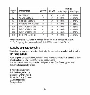
51 VA DEMAND 52 VA MAX DEMAND
53 CURRENT DEMAND 54 CURRENT MAX DEMAND
101 INPUT VOLTAGE L12
102 INPUT VOLTAGE L23
103 INPUT VOLTAGE L31 113 NEUTRAL CURRENT
0 - 100 %
0 - 100 %
0 - 100 %0 - 100 %
0 - 120 %0 - 120 %
0 - 100 %
0 - 100 %
ü üü üü üü üü û ü û ü û ü û
Note : Parameters 1,2,3 are L-N Voltage for 3P 4W & L-L for 3P 3W .Voltage
10. Relay output (Optional) : This is provided with either 1 or 2 relay for pulse as well as for limit switch instrument output
10.1 Pulse Output :
Pulse output is the potential free, very fast acting relay contact which can be used to drive an external mechanical counter for energy measurement.This pulse output can be configured to any of the following parameter through setup parameter screen
1) Active Energy (Import)2) Active Energy (Export) 3)Reactive Energy (Import)4)Reactive Energy (Export) 5)Apparent Energy 6)Ampere hour
instrument’s
37
Parameter Parameter 3P 4W 3P 3WRange
No. Analog Output Limit Output
10 - 120 %
10 - 120 %
10 - 120 %
10 - 120 %
10 - 120 %
10 - 120 %10 - 120 %
10 - 120 %
(1) For Frequency 0% corresponds to 40 Hz & 100% corresponds to 70 Hz.

* System power = 3 x CT(Primary) x PT(Primary)L-N for 3 Phase 4 Wire System power = Root3 x CT(Primary) x PT(Primary)L-L for 3 Phase 3 Wire
Above options are also applicable for Apparent and Reactive Energy.
Ampere Hour:
Divisor 1(CT secondary = 1A Max pulse rate 3600 pulses per Ah **CT secondary = 5A Max pulse rate 720 pulses per Ah **
Divisors 10CT secondary = 1A Max pulse rate 3600 pulses per 10Ah **CT secondary = 5A Max pulse rate 720 pulses per 10Ah **
Default)
38
Pulse Duration 60 ms,100 ms or 200 ms
Divisor
1
10
100
1000
Pulse ratePulse System Power*
1per Wh
1per 10Wh
1per 100Wh
1 per 1000Wh
1per kWh
1per 10kWh
1per 100kWh
1 per 1000kWh
1per Mwh
1per 10MWh
1per 100MWh
1per 1000MWh
Up to 3600W
Up to 3600W
Up to 3600W
Up to 3600W
Up to 3600kW
Up to 3600kW
Up to 3600kW
Up to 3600kW
Above 3600kW
Above 3600kW
Above 3600kW
Above 3600kW
TABLE 3 : Energy Pulse Rate Divisor
1.For Energy Output in Wh
Divisor
1
Pulse ratePulse System Power*
1 per kWh1 per 1000kWh
1 per 1000MWh
Up to 3600WUp to 3600kWAbove 3600kW
2. For Energy Output in Kwh
Divisor
1
Pulse ratePulse System Power*
1 per Mwh1 per 1000Mwh1 per 1000Gwh
Up to 3600WUp to 3600kWAbove 3600kW
3. For Energy Output in Mwh

Divisors 100CT secondary = 1A Max pulse rate 3600 pulses per 100Ah **CT secondary = 5A Max pulse rate 720 pulses per 100Ah **
Divisors 1000CT secondary = 1A Max pulse rate 3600 pulses per 1000Ah **CT secondary = 5A Max pulse rate 720 pulses per 1000Ah **
Pulse duration 60 ms, 100 ms or 200 ms**No. of Pulses per Ampere hour = Maximum Pulses / CT Ratio Where, CT Ratio = (CT primary/ CT Secondary)
10.2 Limit Switch :
Limit switch can be used to monitor the measured parameter ( Ref.Table:2 )in relationwith to a set limit.The limit switch can be configured in one of the four mode given below:-1) Hi alarm & Relay Energized Relay..2) Hi alarm & De-Energized Relay.3) Lo alarm & Energized Relay.4) Lo alarm & De-Energized Relay. Limit switch has user selectable Trip point, Hysteresis, Energizing Delay & De-Energizing delay.
Hi Alarm:
Lo Alarm:
If Hi-Alarm Energized or Hi Alarm De-Energized option is selected then relay will get energized or De-energized,if selected parameter is greater than or equal to trip point.
If Lo-Alarm Energized or Lo Alarm De-Energized option is selected then relay will get energized or De-energized,if selected parameter is less than or equal to trip point.
39

Trip point can be set in the range of 10% to 120 % of nominal value for Hi-Alarm & 10% to 100 % of nominal value for Lo-Alarm.
Trip point:
Hysteresis:
Energizing Delay:
De-Energizing Delay:
Hysteresis can be set in the range of 0.5% to 50 % of set trip point .If Hi-alarm Energized or Hi-alarm De-energized is selected then relay will get De-energized or Energized respectively, if set parameter value is less than HysteresisSimilarly if Lo-alarm Energized or Lo-alarm De-Energized.
The energizing delay can be set in the range from1 to 10 sec.
The De-energizing delay can be set in the range from1 to 10 sec.
Note : In case of lo alarm if trip point is set at 100% then maximum 20% Hysterisis can be set..
Hysterisis point
40

11. RS 485 ( ModBus ) Output :
This supports MODBUS (RS485) RTU protocol( 2-wire ) .instrument
Connection should be made using twisted pair shielded cable. All "A" and "B" connections are daisy chained together. The screens should also be connected to the “Gnd” terminal. To avoid the possibility of loop currents, an Earth connection should be made at one point on the network.Loop (ring) topology does not require any termination load. Line topology may or may not require terminating loads depending on the type and length of cable used. The impedance of the termination load should match the impedance of the cable and be at bothends of the line. The cable should be terminated at each end with a 120 ohm (1/4 Watt min.) resistor.
RS 485 network supports maximum length of 1.2km. Including the Master, a maximum of 32 instruments can be connected in Rs485 network.The permissible address range for the
is between 1 and 247 for 32 instruments. Broadcast Mode (address 0) is not allowed.instrument
The maximum latency time for the is 200ms i.e. this is the amount of time that can pass before the first response character is output.
instrument
After sending any query through software ( of the Master) , it must allow 200ms of time to elapse before assuming that the is not going to respond. If slave does not respond within 200 ms, Master can ignore the previous query and can issue fresh query to the slave.
instrument
41

The each byte in RTU mode has following format:
8-bit binary, hexadecimal 0-9, A-F
2 hexadecimal characters contained in each 8-bit field of the message
4 bytes (32 bits) per parameter.
Floating point format ( to IEEE 754)Most significant byte first (Alternative least significant byte first)
Format of Data Bytes
2 byte Cyclical Redundancy Check (CRC)Error Checking Bytes
1 start bit,8 data bits, least significant bit sent first1 bit for even/odd parity1 stop bit if parity is used; 1 or 2 bits if no parity
Byte format
Communication Baud Rate is user selectable from the front panel between 2400, 4800, 9600, 19200 bps.
Exception Cases : An exception code will be generated when the receives ModBus query with valid parity & error check but which contains some other error ( e.g. Attempt to set floating point variable to an invalid value ) The response generated will be “Function code” Ored with HEX (80H ). The exception codes are listed below
instrument
Function code :
03 Read Holding Registers Read content of read /write location ( 4X )
04 Read input Registers Read content of read only location ( 3X )
16 Presets Multiple Registers Set the content of read / write locations ( 4X )
42

03 Illegal DataValue
Attempt to set a floating point variable to an invalid value
01 Illegal function This function code is not supported by the instrument.
02 Illegal DataAddress
Attempt to access an invalid address or an attempt to read or write part of a floating point value
of 3X registers (Parameters measured by the instruments).Each parameter is held in the 3X registers. Modbus Code 04 is used to access all parameters.
Example :
Two consecutive 16 bit registers represent one parameter. Refer table 4 for the addresses
To read parameter , Volts 3 : Start address= 04 (Hex) Number of registers = 02
Note : Number of registers = Number of parameters x 2
Each Query for reading the data must be restricted to 20 parameters or less. Exceeding the 20 parameter limit will cause a ModBus exception code to be returned.
Query :
Accessing 3 X register for reading measured values:
DeviceAddress
Function Code
Start Address High
Start Address Low
Number ofRegisters Hi
Number ofRegisters Lo
CRCLow
CRCHigh
01 (Hex) 04 (Hex) 00 (Hex) 04(Hex) 00 (Hex) 02(Hex) 30 (Hex) 0A (Hex)
Start Address High : Most significant 8 bits of starting address of the parameter requested.
Start Address low :Least significant 8 bits of starting address of the parameter requested.
43
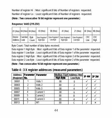
Number of register Hi : Most significant 8 bits of Number of registers requested.
Number of register Lo : Least significant 8 bits of Number of registers requested.
(Note : Two consecutive 16 bit register represent one parameter.)
Response: Volt3 (219.25V)
DeviceAddress
Function Code
ByteCount
Data Register1 High Byte
01 (Hex) 04 (Hex) 04 (Hex) 43 (Hex) 5B (Hex) 41 (Hex) 21 (Hex) 6F (Hex)
Data Register1 Low Byte
Data Register2 High Byte
Data Register2 Low Byte
CRCLow
CRCHigh
9B (Hex)
Byte Count : Total number of data bytes received.
Data register 1 High Byte : Most significant 8 bits of Data register 1 of the parameter requested.Data register 1 Low Byte : Least significant 8 bits of Data register 1 of the parameter requested.
Data register 2 High Byte : Most significant 8 bits of Data register 2 of the parameter requested.
(Note : Two consecutive 16 bit register represent one parameter.)
Data register 2 Low Byte : Least significant 8 bits of Data register 2 of the parameter requested.
Table 4 : 3 X register addresses (measured parameters)
Address(Register)
ParameterNo.
Parameter Modbus Start Address Hex High Byte Low ByteHigh ByteHigh Byte 3P 4W 3P 3W
30001 1 Volts 1 00 030003 2 Volts 2 00 230005 3 Volts 3 00 430007 4 Current 1 00 630009 5 Current 2 00 830011 6 Current 3 00 A30013 7 W1 00 C
ParameterNo.
Parameter3P 4W 3P 3W
ü
û
üü üü üü üü üü üü
44

30023 12 VA3 00 1630025 13 VAR1 00 1830027 14 VAR2 00 1A30029 15 VAR3 00 1C30031 16 PF1 00 1E30033 17 PF2 00 2030035 18 PF3 00 2230037 19 Phase Angle 1 00 2430039 20 Phase Angle 2 00 2630041 21 Phase Angle 3 00 28
30043 22 Volts Ave 00 2A30045 23 Volts Sum 00 2C30047 24 Current Ave 00 2E30049 25 Current Sum 00 3030051 26 Watts Ave 00 3230053 27 Watts Sum 00 34
30055 28 VA Ave 00 3630057 29 VA Sum 00 3830059 30 VAr Ave 00 3A30061 31 VAr Sum 00 3C30063 32 PF Ave 00 3E
û üû üû üû üû üû üû üû üû üû ü
ü üü üü üü üü üü üü üü üü üü üü ü
Address(Register)
ParameterNo.
Parameter Modbus Start Address HexHigh Byte Low ByteHigh ByteHigh Byte 3P 4W 3P 3W
30015 8 W2 00 E
30017 9 W3 00 10
30019 10 VA1 00 12
ParameterNo.
Parameter Modbus Start Address Hex3P 4W 3P 3W
30021 11 VA2 00 14
û üû üû üû ü
45

30065 33 PF Sum 00 4030067 34 Phase Angle Ave 00 4230069 35 Phase Angle Sum 00 4430071 36 Freq 00 4630073 00 4837 Wh Import
30075 00 4A38 Wh Export
30077 39 VARh Import 00 4C30079 40 VARh Export 00 4E30081 41 VAh 00 50
ü û ü üü û ü üü üü üü üü üü ü
Address(Register)
ParameterNo.
Parameter Modbus Start Address HexHigh Byte Low ByteHigh ByteHigh Byte 3P 4W 3P 3W
ParameterNo.
Parameter Modbus Start Address Hex3P 4W 3P 3W
30099
30101
30103
30105
30097
30107
30133
30085
30087
30089
30091
30093
30095
30135
30141
30143
30201
5051
52
53
49
54
67
43
44
45
46
4748
68
71
72
101
VA Demand
VA Max Demand
A Demand
-
A Max Demand
Volts Ave Max
W Demand (Import)
W Max Demand (Import)
W Demand (Export)
W Max Demand (Export)---
Volts Ave Min
Current Ave Max
-
Current Ave Min
VL 1 - 2 ( Calculated )
0000
0000
00
00
00
00
00
00
00
00-
00
00
--
00
00
64
66
68
-
6A
84
54
56
5A-
58
86
8C
-
-
8E
C8
üüüü-
-
--
üüüüüüüüü û
üüüü-
-
--
üüüüüüüü
46
30083 42 Ah 00 52 ü ü

Address(Register)
ParameterNo.
Parameter Modbus Start Address HexHigh Byte Low ByteHigh ByteHigh Byte 3P 4W 3P 3W
ParameterNo.
Parameter Modbus Start Address Hex3P 4W 3P 3W
30203
30205
30207
30209
30211
3021330215
30217
30219
30221
30225
30227
30229
30231
102
103
104
105
106
107108
109
110
111
113
114
115
116
VL 2 - 3 ( Calculated )
VL 3 - 1 ( Calculated )
V1 THD( % )
V2 THD( % )
V3 THD( % )
I1 THD( % )I2 THD( % )
I3 THD( % )
System Voltage THD( % )
System Current THD( % )
I neutral
Run Hour
On Hour
No. Of Interrupts
00
00
00
00
00
0000
00
00
00
00
00
00
00
CA
CC
CE
D0
D2
D4D6
D8
DA
DC
E0
E2
E4
E6
üüüüüüüüüüüüüü
û û üüüüüüüüû üüü
Note : Parameters 1,2,3 are L-N Voltage for 3P 4W & L-L Voltage for 3P 3W .
Each setting is held in the 4X registers .ModBus code 03 is used to read the current setting and code 16 is used to write/change the setting. Refer Table 5 for 4 X Register addresses.
Example : Reading System typeSystem type : Start address= 0A (Hex) Number of registers = 02
Note :Number of registers = Number of Parameters x 2
Accessing 4 X register for Reading & Writing :
47

Query :
Start Address High : Most significant 8 bits of starting address of the parameter requested.
Start Address low :Least significant 8 bits of starting address of the parameter requested.
Number of register Hi : Most significant 8 bits of Number of registers requested.
Number of register Lo : Least significant 8 bits of Number of registers requested.
(Note : Two consecutive 16 bit register represent one parameter.)
Device Address
Function Code
Start Address High
Start Address Low
Number of Registers Hi
Number of Registers Lo
CRC Low
CRC High
01 (Hex)
03 (Hex)
00 (Hex)
0A (Hex)
00 (Hex)
02 (Hex)
E4 (Hex)
09 (Hex)
Response: System Type ( 3phase 4 wire = 3 )
Device Address
Function Code
Byte Count
Data Register1 High Byte
01 (Hex)
03 (Hex)
04 (Hex)
40 (Hex)
Data Register1Low Byte 40 (Hex)
48
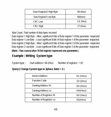
Data Register2 High Byte 00 (Hex)
00(Hex)Data Register2 Low Byte
EE (Hex)CRC Low
CRC High 27 (Hex)
Byte Count : Total number of data bytes received.
Data register 1 High Byte : Most significant 8 bits of Data register 1 of the parameter requested.Data register 1 Low Byte : Least significant 8 bits of Data register 1 of the parameter requested.
Data register 2 High Byte : Most significant 8 bits of Data register 2 of the parameter requested.
(Note : Two consecutive 16 bit register represent one parameter.)
Data register 2 Low Byte : Least significant 8 bits of Data register 2 of the parameter requested.
Example : Writing System type
System type : Start address= 0A (Hex) Number of registers = 02
Query:( Change System type to 3phase 3wire = 2 )
01 (Hex)
10 (Hex)
Device Address
Function Code
00 (Hex)Starting Address Hi
0A(Hex)Starting Address Lo
00 (Hex)Number of Registers Hi
02(Hex)Number of Registers Lo
49

04 (Hex)Byte Count
40 (Hex)Data Register-1High Byte
00(Hex)Data Register-1 Low Byte
00(Hex)
00(Hex)
66 (Hex)
10 (Hex)
Data Register-2 Low Byte
CRC High
CRC Low
Data Register-2 High Byte
Byte Count : Total number of data bytes received.
Data register 1 High Byte : Most significant 8 bits of Data register 1 of the parameter requested.Data register 1 Low Byte : Least significant 8 bits of Data register 1 of the parameter requested.
Data register 2 High Byte : Most significant 8 bits of Data register 2 of the parameter requested.
(Note : Two consecutive 16 bit register represent one parameter.)
Data register 2 Low Byte : Least significant 8 bits of Data register 2 of the parameter requested.
Response:
Device Address
Function Code
Start Address High
Start Address Low
Number of Registers Hi
01 (Hex)
10 (Hex)
00 (Hex)
0A(Hex)
00 (Hex)
Number of Registers Lo 02(Hex)
CRC Low 61 (Hex)
CRC High CA (Hex)
45

Start Address High : Most significant 8 bits of starting address of the parameter requested.
Start Address low :Least significant 8 bits of starting address of the parameter requested.
Number of register Hi : Most significant 8 bits of Number of registers requested.
Number of register Lo : Least significant 8 bits of Number of registers requested.
(Note : Two consecutive 16 bit register represent one parameter.)
Address(Register)
ParameterNo.
Parameter Modbus Start Address HexHigh Byte Low ByteHigh ByteHigh Byte
40007 4 Sys Voltage 00 06
Read / Write
R
40009 5 Sys Current 00 08R40009 5 Sys Current 00 08R
6 Sys Type 00 0A40011 00R/Wp
00 0C
40019
7 Pulse Width 00R/Wp
0040015 8
RS 485 Set-up Code
00
R/Wp
00 1440021 11 Node Address. 00
00 1640023 12 Pulse Divisor 00R/Wp
00 1840025 13 Min Reset 00Wp
00 1A40027 14 Max Reset 00Wp
00 1C40029 15 Analog Out 1- Para Sel 00R/Wp
00 1E40031 16 Analog Out 2- Para Sel 00R/Wp
00 2040033 17 00R/Wp
00 2240035 18 CT Primary 00R/Wp
40001 1 Demand Reset 00 00R/Wp
40003 Demand Period 00 02R 00R/Wp
3 00 0440005 R/Wp
2Energy on RS485
Demand Period
00 1440021 11 . 00R/Wp
00 1640023 12 Pulse Divisor 00
009
0010
40013
40017
Energy ResetRun/On Hour & Interruption Reset
W Wp
Wp
PT Primary
10
0E
12
Table 5 : 4 X register addresses
51

40039 20 - 00 26
Address(Register)
ParameterNo.
Parameter Modbus Start Address HexHigh Byte Low ByteHigh ByteHigh Byte
Read / Write
00 2440037 19 System Power R
40041 21 00 28Register Order/Word Order 00R/Wp
2240043 R/WpCT Secondary
PT Secondary00 2A00
00 2C40045 23 00R/Wp
00 2E40047 24 Relay1 output select 00R/Wp
00 3040049 25
Pulse2/Limit2 Parameter select
00R/Wp
00 3240051 26 Limit1 Trip point 00R/Wp
00 3440053 27 Hysteresis(Limit1) 00R/Wp
00 3640055 28 Limit1 delay(On) 00R/Wp
00 3840057 29 Limit1 delay(Off) 00R/Wp
00 3A40059 30 Relay2 output select 00R/Wp
00 3C40061 31 00R/Wp
00 3E40063 32 Limit2 Trip point 00R/Wp
00 4040065 33 Hysteresis(Limit2) 00R/Wp
00 4240067 34 Limit2 Delay(On) 00R/Wp
00 4440069 35 Limit2 Delay(Off) 00R/Wp
00 4640071 36 Password 00R/W
00 4840073 37 Limit1 Configuration select 00R/Wp
00 4A40075 38 Limit2 Configuration select 00R/Wp
40077 39 -
00 4E40079 40 30mA Noise Current Elimination 00R/Wp
Pulse1/Limit1 Parameter select
- - -
52
Energy digit reset count R/Wp

Explanation for 4 X register :
Address Parameter Description
Demand Reset is used to reset the Demand parameter. A value of zero must be Written to this register to reset the Demand period. Writing any other value will return an error.
40001 Demand Reset
40003 Demand Period Demand period represents demand time in minutes. The applicable values are 8,15,20 or 30. Writing any other value will return an error.
40005
40007 System Voltage This address is read only and displays System Voltage
40009 System Current This address is read only and displays System Current
This address is used to set the System type. Write one of the following value to this address.2 = 3 Phase 3 Wire3 = 3 Phase 4 Wire.Writing any other value will return error .
40011 System Type
40013 Pulse Width of Relay
This address is used to set pulse width of the Pulse output. Write one of the following values to this address: 60 : 60 ms 100 : 100 ms 200 : 200 ms Writing any other value will return error .
40015 Reset Energy Counter
This address is used to reset the Energy Counter. Write zero value to this register to reset the energy counter. Writing any other value will return an error.
53
Energy display on Modbus
This address is used to set energy display on MODBUS in Wh,K w Write one of the following value to this address.1 = 3 = Energy in MWh.
Wh & M h.Energy in Wh. 2 = Energy in KWh.

Address Parameter Description
40017 Run/On Hour &Interruption reset
This address is used to reset the Run/On hour & number of Interruption . Write zero value to this register to reset the Run/On hour & number of Interruption. Writing any other value will return an error.
40019 Rs485 Set-upCode
This address is used to set the baud rate, Parity, Number of stop bits. Refer to Table 6 for details.
40021 Node Address
This register address is used to set Device address between 1 to 247 .
40023 Pulse Divisor
40025 Min - Reset This address is used to reset the Min parameters value. Write Zero value to this register to reset the Min parameters. Writing any other value will return an error.
40027 Max - Reset This address is used to reset the Max parameters value. Write Zero value to this register to reset the Max parameters. Writing any other value will return an error.
40029 Analog Out 1-Para Set
This address is used to set the parameter for Analog Output 1.Write one of the parameter no. As per the options given in Table 2 for Analog & Limit Output Parameters.Writing any other value will return an error.
54
This address is used to set pulse divisor of the Pulse output. Write one of the following values to this address for Wh: 1 : Divisor 1 10 : Divisor 10 100 : Divisor 100 1000 : Divisor 1000 & in KWh & MWh Divisior will be 1 default. Writing any other value will return an error.
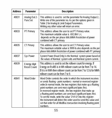
Address Parameter Description
40037 Sys Power System Power (Read Only) is the Nominal system power based on the values of Nominal system volts and Nominal system current.
40041 Word Order Word Order controls the order in which the receives or sends floating - point numbers:- normal or reversed registerorder.In normal mode, the two registers that make up a floating point numbers are sent most significant bytes first.In reversed register mode , the two registers that make up a floating point numbers are sent least significant bytes first.To set the mode, write the value ‘2141.0’ into this register-the instrument will detect the order used to send this value and set that order for all ModBus transaction involving floating point numbers.
instrument
This address allows the user to set CT Primary value.The maximum settable value is 9999 & also depends on the per phase 666.6MVA Restriction of power combined with PT primary
40035 CT Pimary
40039
40031 Analog Out 2-Para Set
This address is used to set the parameter for Analog Output 2..Write one of the parameter no. As per the options given in Table 2 for Analog & Limit Output Parameters.Writing any other value will return an error.
40033 PT Primary This address allows the user to set PT Primary value.The maximum settable value is 692.8kV L-L depends on the per phase 666.6MVA Restriction of power combined with CT primary
55
This address is used to setEnergy on Rs485 is in Wh rollover count can be from 7 to 14.If it is in KWh then rollover count can be from 7 to 12 & for MWh rollover count can be from 7 to 9.
the rollover count for energy. IfEnergy digit Reset Count

Address Parameter Description
40047 Relay1 outputselect
40049 Pulse 1 /Limit 1parameterselect
40051 Limit1 Trip Point
40053 Hysteresis(Limit 1)
40045 PT secondary This address is used to read and write the PT secondary value.Ref Table for the range of PT secondary settable values in
This address is used to select the Relay 1 operation as pulse or Limit. write one of the following values to this address.0 = Pulse output on Relay 1128 (Decimal) = Limit output on Relay 1writing any other value will return an error.
This address is used to assign the Parameter to Relay1If Limit option is selected refer table 2 for parameter number& if Pulse option is selected then refer table 7.
This address is used to set the trip point in %. Any value between 10 to 100 for Lo- alarm & 10 to120 for Hi-alarm can be written to this address. Writing any other value will return an error.
This address is used to set the hysteresis between 0.5 to 50 . Writting any other value will return an error.
This address is used to set the Energizing delay between 1 to 10 . Writting any other value will return an error.
40055 Limit1 Energizing Delay
Section 3.2.1.3
40043 CT secondary This address is used to read and write the CT secondary valuewrite one of the following values to this address.1=1A CT secondary5=5A CT secondarywriting any other value will return an error.
Limit1 de-energizing Delay
This address is used to set the De-Energizing delay between 1 to 10 . Writting any other value will return an error.
56
40057

Address Parameter Description
40059 Relay 2 output select
40061 Pulse 2/Limit 2Parameter select
This address is used to select the Relay 2 operation as pulse or Limit. write one of the following values to this address.0 = Pulse output on Relay 2128 (decimal) = Limit output on Relay 2writing any other value will return an error.
40063 Limit 2 Trip point
This address is used to assign the Parameter to Relay2If Limit option is selected refer table 2 for parameter number& if Pulse option is selected then refer table 7.
This address is used to set the trip point in %. Any value between 10 to 100 for Lo- alarm & 10 to120 for Hi-alarm can be written to this address. Writing any other value will return an error.
This address is used to set the hysteresis between 0.5 to 50 . Writting any other value will return an error.
40065
40067 This address is used to set the Energizing delay between 1 to 10 . Writting any other value will return an error.
This address is used to set the De-Energizing delay between 1 to 10 . Writting any other value will return an error.
40065 Hysteresis(Limit 2)
40067 Limit 2 Energizingdelay
40069 Limit 2 De-Energizingdelay
40071 Password This address is used to set & reset the password. Valid Range of Password can be set is 0000 - 9999 .1) If password lock is present & if this location is read it will return zero.2) If Password lock is absent & if this location is read it will return One.
57
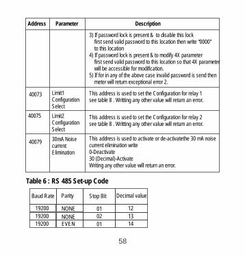
Address Parameter Description
3) If password lock is present & to disable this lock first send valid password to this location then write “0000” to this location4) If password lock is present & to modify 4X parameter first send valid password to this location so that 4X parameter will be accessible for modification.5) If for in any of the above case invalid password is send then meter will return exceptional error 2.
This address is used to set the Configuration for relay 2see table 8 . Writting any other value will return an error.
40073 Limit1Configuration Select
40079 30mA Noise current Elimination
Limit2Configuration Select
This address is used to set the Configuration for relay 1see table 8 . Writting any other value will return an error.
This address is used to activate or de-activatethe 30 mA noise current elimination write 0-Deactivate30 (Decimal)-ActivateWriting any other value will return an error.
Table 6 : RS 485 Set-up Code
19200 NONE19200 EVEN
19200 NONE
Baud Rate Parity Stop Bit Decimal value
01
01
02 1314
12
58
40075

EVEN
19200
9600
9600
9600
NONE
NONE
ODD
Baud Rate Parity Stop Bit Decimal value
01
02
01
01
15
08
09
10ODD9600
4800
4800NONE
NONE48004800
2400
2400
2400
2400
NONE
NONE
ODD
EVEN
ODDEVEN
02
01
01
01
0201
01
01
01 11
04
05
06
07
00
01
0203
NOTE : Codes not listed in the table above may give rise to unpredictable results including loss of communication. Excise caution when attempting to change mode via direct Modbus writes.
4
Export Reactive Energy
Apparent Energy
Import Reactive Energy
Code
1
0
2
3
Configuration
Import Active Energy
Export Active Energy
Table 7 : Pulse1 & Pulse2 Configuration select
59

Lo- alarm & relayDe-energizedLo- alarm & Energized relay
Code
1
0
2
3
Configuration
Hi- alarm & Energized relay
Hi- alarm & De-e relaynergized
Table 8 :Limit1 & Limit2 Configuration select
11.1 User Assignable Modbus Registers:
This contains the 20 user assignable registers in the address range of 0x200 (30513) to 0x226 (30551) (see Table 9).Any of the parameter addresses ( 3X register addresses Table 4)) accessible in the instrument can be mapped to these 20 user assignable registers.Parameters (3X registers addresses ) that resides in different locations may be accessed by the single request by re-mapping them to adjacent address in the user assignable registers area. The actual address of the parameters ( 3X registers addresses) which are to be assessed via address 0x200 to 0x226 are specified in 4x Register 0x200 to 0x213 (see Table 10).
instrument
30513 257 00
Modbus Start Address (Hex)
Assignable Reg 130515 258 0202Assignable Reg 2
30517 259 0402Assignable Reg 3
30519 260 0602Assignable Reg 4
30521 261 0802Assignable Reg 5
30523 262 0A02Assignable Reg 6
Table 9 : User Assignable 3X Data Registers
Address(Register)
ParameterNumber. Assignable Register
02
High Byte Low Byte
60

30533 267 1402Assignable Reg 11
30535 268 1602Assignable Reg 12
30537 269 1802Assignable Reg 13
30539 270 1A02Assignable Reg 14
30541 271 1C02Assignable Reg 15
30543 272 1E02Assignable Reg 16
30545 273 2002Assignable Reg 17
30547 274 2202Assignable Reg 18
30549 275 2402Assignable Reg 19
30551 276 2602Assignable Reg 20
Modbus Start Address (Hex)
30525 263 0C02Assignable Reg 7
30527 264 0E02Assignable Reg 8
30529 265 1002Assignable Reg 9
Address(Register)
ParameterNumber. Assignable Register High Byte Low Byte
30531 266 1202Assignable Reg 10
Table 10 : User Assignable mapping register ( 4X registers)
40514 258 Mapped Add for register #0x0202 02 01
40515 259 Mapped Add for register #0x0204 02 02
260 Mapped Add for register #0x0206 02 034051602 0440517 261 Mapped Add for register #0x0208
02 0540518 262 Mapped Add for register #0x020A
0640519 263 Mapped Add for register #0x020C 02
0740520 264 Mapped Add for register #0x020E
0040513 257 Mapped Add for register #0x0200 02
02
Modbus Start Address (Hex)Address(Register)
ParameterNumber. Mapping Register High Byte Low Byte
61

02 0840521 265 Mapped Add for register #0x0210
0902
0A02
40522 266 Mapped Add for register #0x0212
40523 267 Mapped Add for register #0x0214
Modbus Start Address (Hex)Address(Register)
ParameterNumber. Mapping Register High Byte Low Byte
0B02
0C02
0D02
0E02
0F02
1002
1102
1202
1302
40524 268 Mapped Add for register #0x0216
40525 269 Mapped Add for register #0x021840526 270 Mapped Add for register #0x021A
40527 271 Mapped Add for register #0x021C
40528 272 Mapped Add for register #0x021E
40529 273 Mapped Add for register #0x0220
40530 274 Mapped Add for register #0x0222
40531 275 Mapped Add for register #0x0224
40532 276 Mapped Add for register #0x0226
Example :Assigning parameter to user assignable registersTo access the voltage2 (3X address 0x0002) and Power Factor1 (3X address 0x001E) through user assignable register assign these addresses to 4x register (Table 10 ) 0x0200 and 0x0201 respectively .
Assigning Query:
01 (Hex)Device Address
10 (Hex)Function Code02 (Hex)Starting Address Hi00 (Hex)Starting Address Lo00 (Hex)*Number of Registers Hi
02(Hex)*Number of Registers Lo
62

00 (Hex)1E (Hex)CB (Hex)
07 (Hex)
00 (Hex)
04 (Hex)
02 (Hex)
Data Register-2 Low Byte
Byte Count
CRC High
Data Register-1 Low Byte
Data Register-2 High Byte
Data Register-1High Byte }Voltage 2 *(3X Address 0x0002)
Power Factor 1 *(3X Address 0x001E)
}CRC lOW
Reading Parameter data through User Assignable Registers:
In assigning query Voltage2 and Power Factor1 parameters were assigned to 0x 200 and 0x201(Table10) which will point to user assignable 3xregisters 0x200 and 0x202 (table9). So to read Voltage2 and PowerFactor1 data reading query should be as below.
Device Address
Function CodeStart Address High
Start Address Low
Number of Registers HiNumber of Registers Lo
CRC Low
CRC High
01 (Hex)
10 (Hex)
02 (Hex)
00 (Hex)
00 (Hex)02 (Hex)
40 (Hex)
70 (Hex)
Response :
63

Query:
Device Address
Function Code
Start Address High
Start Address LowNumber of Registers HiNumber of Registers Lo
CRC Low
CRC High
01 (Hex)04 (Hex)
02 (Hex)
00 (Hex)
00 (Hex)04 (Hex) **F0 (Hex)
71 (Hex)
Start Address High : Most significant 8 bits of User assignable register. starting address of
Start Address low :Least significant 8 bits of starting address of User assignable register. Number of register Hi : Most significant 8 bits of Number of registers requested.
Number of register Lo : Least significant 8 bits of Number of registers requested.
**Note : Two consecutive 16 bit register represent one parameter. Since two parameters are requested four registers are required
Response : (Volt2 = 219.30 / Power Factor1 = 1.0)
01 (Hex)
04 (Hex)
Device Address
Function Code08 (Hex)
43 (Hex)5B (Hex)
4E (Hex)
Byte count
} Voltage 2 DataData Register-1 Low Byte
Data Register-2 High Byte
Data Register-1High Byte
04 (Hex)Data Register-2 Low Byte
64

User Assignable mapping Registers ( 4X Registers Table10 )
Voltage 2 (0x0002)
Power Factor 1 (0x001E)
Wh Import (0x0048)
Frequency (0x0046)
VAh (0x0050)
Current 1 (0x0006)
User Assignable Data Registers ( 3X Registers Table 9 )
0x200 (16 bit)
0x201(16 bit)
0x203(16 bit)
0x202(16 bit)
0x204(16 bit)
0x205(16 bit)
0x206(16 bit)
0x207(16 bit)
0x224(16 bit)
0x225(16 bit)
0x226(16 bit)
0x227(16 bit)
0x200
0x202
0x204
0x206
0x224
0x226
0x200
0x201
0x202
0x203
0x212
0x213
(Starting Address)
}00 (Hex)00 (Hex)79 (Hex)
3F (Hex)
3F (Hex)80 (Hex)
Data Register-4 Low Byte
CRC High
CRC Low
Data Register-3 Low Byte
Data Register-4 High Byte
Data Register-3 High Byte
Power Factor 1Data
(Starting Address)
65

12. Phaser Diagram :
To get the data through User assignable Register use following steps:1) Assign starting addresses(Table3) of parameters of interest to a “User assignable mapping registers” in a sequence in which they are to be accessed (see section “Assigning parameter to user assignable registers”) 2) Once the parameters are mapped data can be acquired by using “User assignable data register “ Starting address . i.e to access data of Voltage2, Power factor1,Wh import, Frequency send query with starting address 0x200 with number of register 8 or individually parameters can be accessed for example if current1 to be accessed use starting address 0x212. (See section Reading Parameter data through User Assignable Registers)
InductiveCapacitive
Capacitive Inductive90 degrees (0.000)
0 degrees (+1.000)180 degrees (-1.000)
270 degrees (0.000)
-+
2
4+-
66
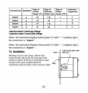
Connections Quadrant
Power ( P )
Sign of Active
Power ( Q )
Sign of Reactive
Factor ( PF )
Sign of Power
Inductive /Capacitive
Import 1 + P + Q + L
Import 4 + P - Q + C
Export 2 - P + Q - C
Export 3 - P - Q - L
Inductive means Current lags VoltageCapacitive means Current leads Voltage
13. Installation
Mounting is by four side clamps, slide the side clamps through side slot till side clamp gets firmly locked in a groove (Refer fig.) Consideration should be given to the space required behind the instrument to allow for bends in the connection cables.
SLIDE IN THIS DIRECTION AND LOCKPANEL
Meter
When the instrument displays Active power ( P )with “ + ” ( positive sign ) ,
the connection is “ Import ” .
When the instrument displays Active power ( P )with “ - ” ( negative sign ) ,
the connection is “ Export ” .
67

1 .1 EMC Installation 3 RequirementsThis product has been designed to meet the certification of the EU directives when installed to a good code of practice for EMC in industrial environments, e.g.
1. Screened output and low signal input leads or have provision for fitting RF suppression components, such as ferrite absorbers, line filters etc., in the event that RF fields cause problems.
Note: It is good practice to install sensitive electronic instruments that are performing critical functions, in EMC enclosures that protect against electrical interference which could cause a disturbance in function.
2. Avoid routing leads alongside cables and products that are, or could be, a source of
Caution1. In the interest of safety and functionality this product must be installed by
a qualified engineer, abiding by any local regulations.
2. Voltages dangerous to human life are present at some of the terminal connections of this unit. Ensure that all supplies are de-energised before attempting any connection or disconnection.
3. These products do not have internal fuses therefore external fuses must be used to ensure safety under fault conditions.
As the front of the enclosure conforms to IP54 it is protected from water spray from all directions, additional protection to the panel may be obtained by the use of an optional panel gasket.
The terminals at the rear of the product should be protected from liquids.
The should be mounted in a reasonably stable ambientinstrumenttemperature and where the operating temperature is within the range
0-10 to 55 C . Vibration should be kept to a minimum and the product should not be mounted where it will be subjected to excessive direct sunlight.
interference.
68
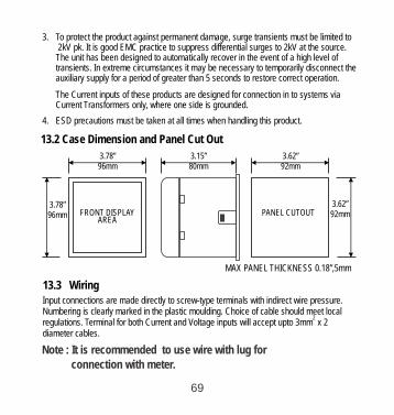
4. ESD precautions must be taken at all times when handling this product.
3. To protect the product against permanent damage, surge transients must be limited to 2kV pk. It is good EMC practice to suppress differential surges to 2kV at the source. The unit has been designed to automatically recover in the event of a high level of transients. circumstances it may be necessary to temporarily disconnect the In extreme auxiliary supply for a period of greater than 5 seconds to restore correct operation.
The Current inputs of these products are designed for connection in to systems via Current Transformers only, where one side is grounded.
13.2 Case Dimension and Panel Cut Out
3.78”96mm
FRONT DISPLAYAREA
3.78”96mm
3.15”80mm
3.62”92mm
PANEL CUTOUT3.62”92mm
MAX PANEL THICKNESS 0.18”,5mm
13.3 WiringInput connections are made directly to screw-type terminals with indirect wire pressure. Numbering is clearly marked in the plastic moulding. Choice of cable should meet local
2regulations. Terminal for both Current and Voltage inputs will accept upto 3mm x 2 diameter cables.
Note : It is recommended to use wire with lug for connection with meter.
69
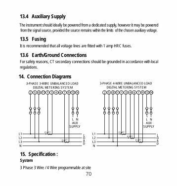
1 . Connection 4 Diagrams3-PHASE 4-WIRE UNBALANCED LOAD
DIGITAL METERING SYSTEM
2 5 8 11 1 3 4 6 7 9 13 14
L NAUX
SUPPLY
P1 S1
S1P1
P1 S1
L1 L2L3N
L OAD
3-PHASE 3-WIRE UNBALANCED LOADDIGITAL METERING SYSTEM
P1 S1
P1 S1
L NAUX
SUPPLY
L1 L2L3N
L OAD
2 5 8 3 4 6 7 9
13.4 Auxiliary Supply
The should ideally be powered from a dedicated supply, however it may be instrument powered signal source, provided the source remains within the limits from the of the chosen auxiliary voltage.
13.5 FusingIt is recommended that all voltage lines are fitted with 1 amp HRC fuses.
13.6 Earth/Ground ConnectionsFor safety reasons, CT secondary connections should be grounded in accordance with local
regulations.
15. Specification :System
3 Phase 3 Wire / 4 Wire programmable at site
70

System CT primary values Std. Values from 1 to 9999A
Inputs
Nominal input voltage (AC RMS) (Three wire and Four wire)
Max continuous input voltage
Max short duration input voltage
Nominal input voltage burden
Phase-Neutral 63.5 / 133 / 239.6 / 254 VL-N
L-L
120% of Rated Value
2 x Rated Value(1s application repeated 10 times
at 10s intervals)
0 .2VA approx. per phase
Max continuous input current 120% of Rated Value
Nominal input current burden 0 .6VA approx. per phase
Max short duration current input 20 x (1s application repeated Rated Value5 times at 5 min. intervals)
Auxiliary
Standard nominal Auxillary supply voltages & Frequency
d.c. supply voltage tolerance +10 % / -10 % of Rated Value
a.c. supply frequency range 45 to 66 Hz
1 00 - 250V AC- DC (45-66Hz),12 - 48V DC
Nominal input current 5A AC rms
(1 or 5 Amp secondaries)
71
a.c. supply voltage tolerance +10 % / -10 % of Rated Value
Line-Line 110 / 230 / 415 / 440 V

Power Factor ± 1 % of Unity
a.c. supply burden 6.5 V A
d.c. supply burden 3W
Operating Measuring Ranges
Voltage 5 .. 120 % of Rated Value
Current 5 .. 120 % of Rated Value
Frequency 40 .. 70 Hz
Power Factor 0.5 Lag ... 1 ... 0.8 Lead
Accuracy
Voltage ± 0.5 % of range
C urren t ± 0.5 % of range
Frequency 0.15% of mid frequency
Active Energy ± 1.0 % of range
± 0.5 % of range Active Power
± 0.5 % of range Re- Active Power
± 0.5 % of range Apparent Power
Apparant Energy ± 1.0 % of range
Accuracy 1:
Re - Active Energy ± 1.0 % of range
72

Neutral Current ± 4 % of range.
Analog Output ± 1 % of Output end value
Angle ± 1 % of range
Total Harmonic Distortion
Vo ltage
C urren t
± 0.5 % of range
± 0.5 % of range
Frequency 0.15% of mid frequency
Active Energy ± 0.5 % of range
± 0.5 % of range Active Power
± 0.5 % of range Re- Active Power
± 0.5 % of range Apparent Power
Re - Active Energy
Apparant Energy ± 0.5 % of range
Power Factor ± 1 % of Unity
Angle ± 1 % of range
Analog Output ± 1 % of Output end value
Total Harmonic Distortion
Accuracy 0.5:
± 0.5 % of range
Neutral Current ± 4 % of range
73

Voltage
C urren t
± 0.2 % of range
± 0.2 % of range
Frequency 0.15% of mid frequency
Active Energy ± 0.2 % of range
± 0.2 % of range Active Power
± 0.2 % of range Re- Active Power
± 0.2 % of range Apparent Power
Re - Active Energy
Apparant Energy ± 0.2 % of range
Power Factor ± 1 % of Unity
Angle ± 1 % of range
Analog Output ± 1 % of Output end value
Total Harmonic Distortion ± 1 %
Accuracy 0.2:
± 0.2 % of range
Neutral Current ± 4 % of range
Reference conditions for Accuracy :
023 C 0+ 2 C
50 or 60Hz 2%±
Reference temperature
Input frequency
74

Auxiliary supply frequency Rated Value + 1 %
Voltage Range 50... 100% of Nominal Value.
Current Range 10... 100% of Nominal Value.
Power cosØ / sinØ = 1
10... 100% of Nominal Current &50... 100% of Nominal Voltage.
For Active / Reactive Power & Energy
60... 100% of Nominal Value for THD.
20... 100% of Nominal Value for THD.
Sinusoidal (distortion factor 0.005)
Rated Value + 1 %
Input waveform
Auxiliary supply voltage
Power Factor / Phase Angle 40... 100% of Nominal Current &
50... 100% of Nominal Voltage.
Nominal range of use of influence quantities for measurands
50 .. 120 % of Rated Value
10 .. 120 % of Rated Value
Rated Value + 10 %
00 to 50 C
Voltage
Current
Input frequency
Temperature
Auxiliary supply voltage
Auxiliary supply frequency
Rated Value + 10 %
Rated Value + 10 %
75

Error change due to variation of an influence quantity
2 * Error allowed for the referencecondition applied in the test.
Temperature Coefficient00.025% / C for Voltage (50..120% of Rated Value)
(For Rated value range of use 0.05% / C for Current ( 10..120% of Rated Value ) 0
00... 50 C )
Approx. 1 seconds Update
Display
3.5” Graphical LCD, resolution 320x240 pixelsTFT LCD
ControlsResistive Touch screenUser Interface
Standards
IEC 61326
10V/m min-Level 3 industrial low level
electromagnetic radiation environment
IEC 61000-4-3.
IEC 61010-1 , Year 2001
EMC Immunity
Safety
IEC 60529IP for water & dust
Isolation
2.2 kV RMS 50 Hz for 1 minutebetween all electrical circuits
Dielectric voltage withstandtest between circuits andaccessible surfaces
76
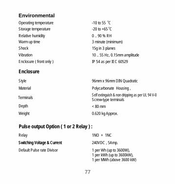
Self extinguish & non dripping as per UL 94 V-0
Environmental
-10 to 55 C0
-20 to +65 C0
0 .. 90 % RH 3 minute (minimum)
15g in 3 planes
10 .. 55 Hz, 0.15mm amplitude
IP 54 as per IEC 60529
Operating temperature
Storage temperature
Relative humidity
Warm up time
Shock
Vibration
Enclosure ( front only )
Enclosure
96mm x 96mm DIN Quadratic
Polycarbonate Housing ,
Screw-type terminals
< 80 mm
0.620 kg Approx.
Style
Material
Terminals
Depth
Weight
Pulse output Option ( 1 or 2 Relay ) :
1NO + 1NCRelay
240VDC , 5Amp.Switching Voltage & CurrentSwitching Voltage & Current
1 per Wh (up to 3600W), 1 per kWh (up to 3600kW), 1 per MWh (above 3600 kW)
Default Pulse rate Divisor
77

ModBus ( RS 485 ) Option :
ModBus ( RS 485 )Protocol
19200 , 9600 , 4800 or 2400Baud Rate( Programmable )
Odd or Even, with 1 stop bit,ParityOr None with 1 or 2 stop bits
Analog Output Option :
0 ... 1mA dc into 0 - 2 kohmLinear
Uni-directional, internally powered .
4 ... 20mA dc into 0 - 500 ohm
Uni-directional, internally powered.
Pulse rate Divisors Programmable on site
1 per 10Wh (up to 3600W), 1 per 10kWh (up to 3600kW), 1 per 10MWh (above 3600 kW)
10
1 per 100Wh (up to 3600W), 1 per 100kWh (up to 3600kW), 1 per 100MWh (above 3600 kW)
100
1 per 1000Wh (up to 3600W), 1 per 1000kWh (up to 3600kW), 1 per 1000MWh (above 3600 kW)
1000
60ms , 100ms or 200msPulse Duration
Note : Above conditions are also applicable for Reactive & Apparent Energy .
78

N/O N/C COM
Relay 1
N/O N/C COM
Relay 2
N/O N/C COM
Relay 1
16. Connection for Optional Pulse Output / RS 485
/ Analog Output : ( rear view of the instrument )
1. One Pulse Output (One Limit Output)
2. Two Pulse Output ( Two Limit Output)
B A Gnd
RS 485
3. RS 485 Output
79
A1 A2 Gnd
4 -20 mA
Gnd
4. Two Analog Output

A1 A2 Gnd
0 - 1mA
N/O N/C COM
Relay 2
Gnd
N/O N/C COM
Relay 2
B A Gnd
RS 485
5. One Pulse + RS 485 Output (One Limit)
6. One Pulse + Two Analog Output (One Limit)
80
7. RS 485 + Two Analog Output
A1 A2 Gnd
4 -20 mA
B A Gnd
RS 485 Gnd
8. Pulse + Two Analog OutputRS 485 Output + One (One Limit)
A1 A2 Gnd
0 - 1mA
N/O N/C COM
Relay 2
B A Gnd
RS 485 Gnd
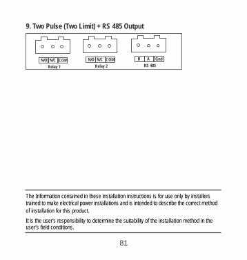
The Information contained in these installation instructions is for use only by installers trained to make electrical power installations and is intended to describe the correct method
It is the user's responsibility to determine the suitability of the installation method in the
of installation for this product.
user’s field conditions.
9. Two Pulse + RS 485 Output (Two Limit)
N/O N/C COM
Relay 1
N/O N/C COM
Relay 2
B A Gnd
RS 485
81


RISH Master 3480
212.6Vrms
213.0Vrms
212.7
Vrms48.11Hz
2.222ms/Div
V/Div50.82


![Operating Manual - PSP 606 (Volume 2)OPERATING MANUAL PSP 606 MASTER CAUTION AND INDICATOR LIGHTS ELEVATOR SPOILER CONTROL SWITCHES AND SPLRS INOP WARNING LIGHT jT] SPOILER CONTROL](https://img.pdfslide.us/doc/110x75/5e6f094bd25d635af94b7956/operating-manual-psp-606-volume-2-operating-manual-psp-606-master-caution-and.jpg)