Embed Size (px)
Citation preview

Bridge Master E Radar Operating Instructions
NAVI-TRAINER 4000 (v. 4.51). Navigational Bridge. 160
BRIDGE MASTER E RADAR OPERATING INSTRUCTIONS
Radar selection and radar parameters adjusting see the first section of this chapter.
Getting Started Standby Mode The radar always appears in standby mode.
Selection of TX A (S) or TX A (X) type of transiver:
In standby mode, a number of functions are available which allow the display to be set up for operation.
The following functions can be accessed from standby mode:
• Brilliance (DEFAULT BRILL, BRILLIANCE +, BRILLIANCE -, to select the display palette: DAY and 3 NIGHT);
• Cursor data;
• Range selection;
• User data;
• Heading;
• Speed;
• Presentation & Motion modes;
Bridge Master E Radar Operating Instructions
Chapter 5. Transas Radar/Arpa Imitators. 161
• ARPA Limits and Settings;
• Alarms;
• System (exit from BridgeMaster E radar).
Transmit Mode After adjusting of the required functions in standby mode, press TRANSMIT soft key.
Using the Radar Controls Control Panels There are two types of control panel in current use for controlling the radar, a Simple Control Panel and an optional Dedicated Control Panel.
Simple Control Panel The simple control panel is made up of a number of modules which are usually mounted immediately under the display monitor. A simple pointing device (joystick or tracker-ball), with two associated keys (left and right), is used to control the radar and its display. The joystick/tracker-ball controls the position of the on-screen cursor which is displayed as a small white arrow when positioned outside the radar circle, see The On-screen Cursor later in this chapter.
Selections are made by positioning the on-screen cursor over an object or caption and clicking (press and release) with the “left” key. The left key is duplicated on the left hand side of the control panel, to enable two handed operation. The “right” key is used on some items to provide additional functionality when available.
Note: Throughout this manual, instructions to “left click” or “right click” relate to a press-and-release of either of the left keys or the right key. Similarly, references to the “cursor control” relate to the joystick or tracker ball depending on which is fitted.
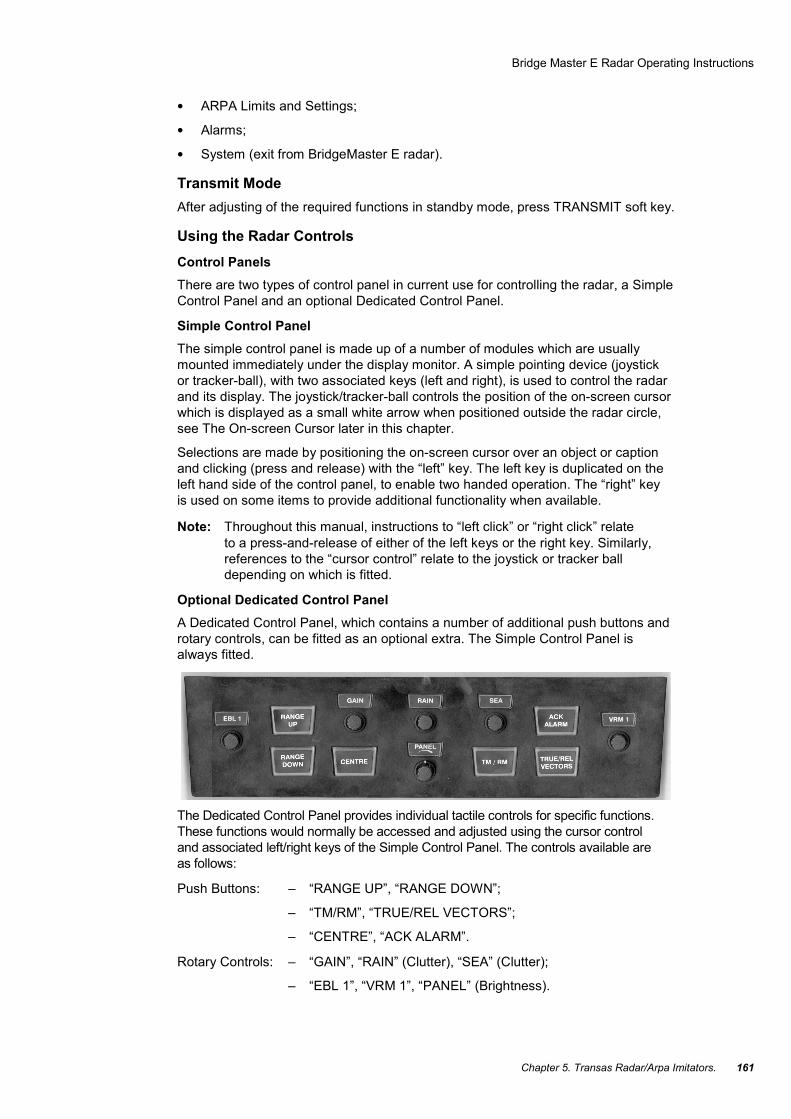
Optional Dedicated Control Panel A Dedicated Control Panel, which contains a number of additional push buttons and rotary controls, can be fitted as an optional extra. The Simple Control Panel is always fitted.
The Dedicated Control Panel provides individual tactile controls for specific functions. These functions would normally be accessed and adjusted using the cursor control and associated left/right keys of the Simple Control Panel. The controls available are as follows:
Push Buttons: – “RANGE UP”, “RANGE DOWN”;
– “TM/RM”, “TRUE/REL VECTORS”;
– “CENTRE”, “ACK ALARM”.
Rotary Controls: – “GAIN”, “RAIN” (Clutter), “SEA” (Clutter);
– “EBL 1”, “VRM 1”, “PANEL” (Brightness).

Bridge Master E Radar Operating Instructions
NAVI-TRAINER 4000 (v. 4.51). Navigational Bridge. 162
The On-screen Cursor When the on-screen cursor is outside the video circle it is displayed as a small white arrow, referred to as the screen cursor. As the cursor passes into the video circle it changes and is displayed as a small white cross, referred to as the video cursor.
Screen Cursor
As the screen cursor moves over a caption or item which can be accessed, its box is highlighted (drawn in white), and two small boxes (representing the left and right keys) appear next to the arrowhead cursor. One or both of these boxes is filled in white to indicate which key(s) are active and available for selection, see example left.
Note: For reasons of clarity and to avoid conflicting information, the screen cursor is shown without its associated left/right key boxes in the diagrams throughout the rest of the manual.
If a caption box is not highlighted as the cursor passes over it, it indicates that the caption or item inside the box cannot be accessed in the current mode.
Drop down menu options are highlighted in yellow as the cursor passes over them. If a particular option is not available it will not be highlighted. Options, which can never be selected because of the current radar configuration, are NOT shown.
If an adjustable parameter is selected, the cursor will disappear and the parameter is displayed in yellow (as a number or control bar). If an adjustment is not made within 10 seconds, the parameter will be automatically deselected, and the cursor will reappear.
Video Cursor
Whenever the video cursor is displayed, a dialog box giving a readout of the cursor’s position within the video circle, replaces the usual function soft keys shown in the bottom right hand corner of the display. By default this box gives cursor range and bearing (from own ship) and cursor lat/long.
Note: Soft keys are small, boxed areas of the screen, usually containing a single caption, which respond in much the same way as the dedicated function keys of a computer keyboard.

Bridge Master E Radar Operating Instructions
Chapter 5. Transas Radar/Arpa Imitators. 163
In TRANSMIT mode, the range and bearing of the cursor are relative to own ship’s position. In STANDBY mode, the range and bearing are relative to the centre of the video circle.
Note: If, when in TRANSMIT, own ship’s position is lost, or there is a compass error, the lat/long readings are replaced by dashes.
Soft Keys and Fixed Menus
A series of functional soft keys are displayed in the bottom right hand corner of the display.
A left click on any one of these keys will reveal a fixed menu and a new set of soft keys associated with that menu. The menu appears in the area immediately above the soft keys.
A right click on some of the function soft keys will provide additional functionality.
Items from the menu are usually selected by a left click.
Restricted Access when in Edit Mode Some of the soft key functions permit editing as part of their functionality. For example, Guard Zone Editing, Index Line Editing. When an edit mode is selected a permanent prompt appears in the help area and access to some of the normal operating facilities is restricted.
As editing is usually performed within the video circle, the following picture related facilities are unavailable during editing:
• Off-centering own ship by dragging;
• Changing ERBL/VRM by dragging;
• Acquiring or Cancelling Targets;
• Selecting from the Target Tote;
• Selecting a new Speed Mode;
• Aligning the Compass.

Bridge Master E Radar Operating Instructions
NAVI-TRAINER 4000 (v. 4.51). Navigational Bridge. 164
Drop Down Menus Where there are a number of fixed selections for a particular parameter, for example RANGE in the top left hand corner of the display, a left click will reveal a drop down menu of the alternatives available.
A drop down menu is usually displayed in the vicinity of the screen cursor when the selection is made. Once a menu is displayed, the cursor is restricted to the area within the menu and selections are made with a left click. A right click will close the menu without taking further action (i.e. Cancel).
Selecting a Mode of Operation From the STANDBY display, there are two mode selections available.
Transmit The normal operational mode. The antenna is rotating and the transceiver transmits and receives radar pulses enabling a radar picture to be displayed.
Initialisation The system initialisation mode. This is used to set up the system parameters during installation.
The soft keys for selecting these modes of operation are located in the bottom left hand corner of the display.
To Select a Mode 1. Use the cursor control to position the screen cursor over the soft key for the
mode required. (Usually TRANSMIT).
2. Left click to select.
Bridge Master E Radar Operating Instructions
Chapter 5. Transas Radar/Arpa Imitators. 165
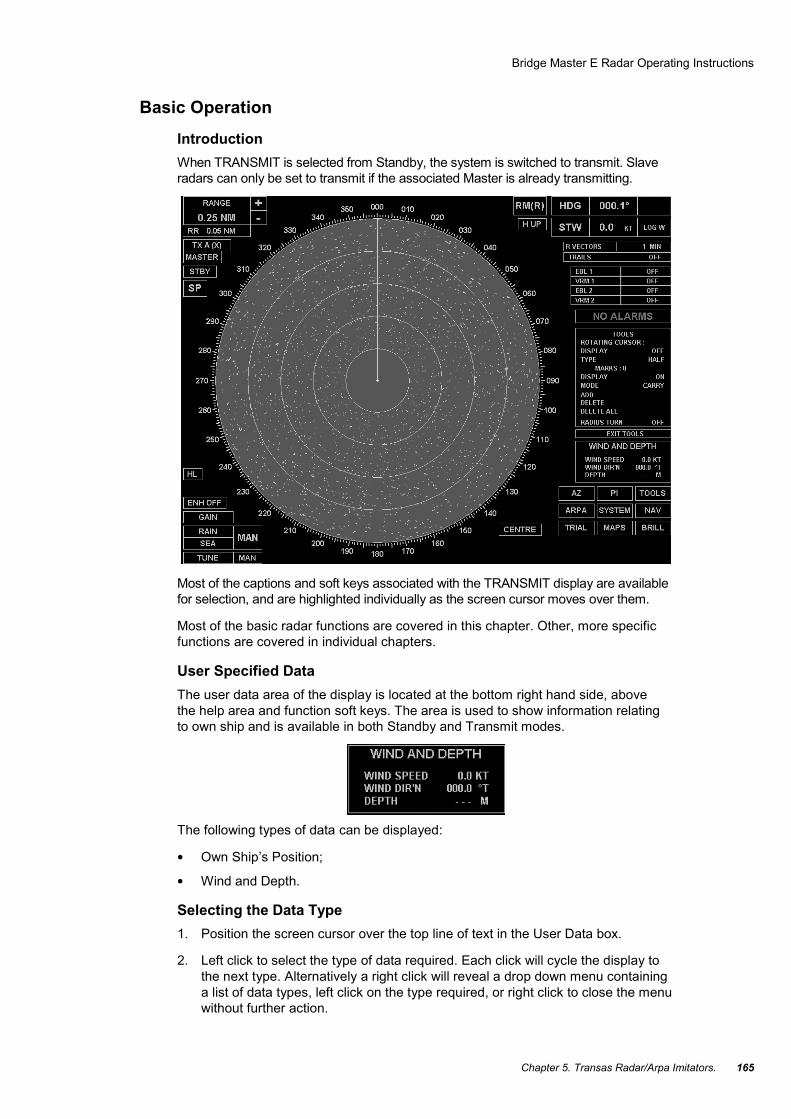
Basic Operation Introduction When TRANSMIT is selected from Standby, the system is switched to transmit. Slave radars can only be set to transmit if the associated Master is already transmitting.
Most of the captions and soft keys associated with the TRANSMIT display are available for selection, and are highlighted individually as the screen cursor moves over them.
Most of the basic radar functions are covered in this chapter. Other, more specific functions are covered in individual chapters.
User Specified Data The user data area of the display is located at the bottom right hand side, above the help area and function soft keys. The area is used to show information relating to own ship and is available in both Standby and Transmit modes.
The following types of data can be displayed:
• Own Ship’s Position;
• Wind and Depth.
Selecting the Data Type 1. Position the screen cursor over the top line of text in the User Data box.
2. Left click to select the type of data required. Each click will cycle the display to the next type. Alternatively a right click will reveal a drop down menu containing a list of data types, left click on the type required, or right click to close the menu without further action.

Bridge Master E Radar Operating Instructions
NAVI-TRAINER 4000 (v. 4.51). Navigational Bridge. 166
Data Displays When specific data is unavailable, the associated readout is replaced with dashes.
Own Ship’s Position The source can be any one of the following: (DGPS), (GPS).
If there is a Position alarm, the lat/lon is displayed in RED.
Wind and Depth Either TRUE or REL (Relative) wind speed is displayed depending on the data received from the sensor. The wind bearing is displayed relative to own ship’s heading.
Range Scales & Range Rings The radar range scale can be selected from a list of preset values. A set of fixed range rings, displayed as a number of equally spaced concentric circles (normally six), can also be switched ON or OFF. Range scale selection can be made in both Standby and Transmit modes. Range rings cannot be selected or displayed in Standby.
The current range scale and range ring selections are given in the top left hand corner of the display. The ranges are displayed in nm.
Choosing the Appropriate RANGE Scale To ensure the best detection of small targets amongst sea clutter, always select the shortest range scale consistent with operational requirements.
Bridge Master E Radar Operating Instructions
Chapter 5. Transas Radar/Arpa Imitators. 167
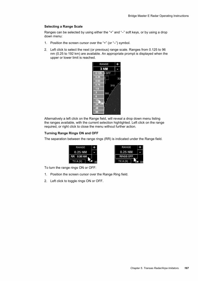
Selecting a Range Scale Ranges can be selected by using either the “+” and “–” soft keys, or by using a drop down menu:
1. Position the screen cursor over the “+” (or “–”) symbol.
2. Left click to select the next (or previous) range scale. Ranges from 0.125 to 96 nm (0.25 to 192 km) are available. An appropriate prompt is displayed when the upper or lower limit is reached.
Alternatively a left click on the Range field, will reveal a drop down menu listing the ranges available, with the current selection highlighted. Left click on the range required, or right click to close the menu without further action.
Turning Range Rings ON and OFF The separation between the range rings (RR) is indicated under the Range field.
To turn the range rings ON or OFF:
1. Position the screen cursor over the Range Ring field.
2. Left click to toggle rings ON or OFF.

Bridge Master E Radar Operating Instructions
NAVI-TRAINER 4000 (v. 4.51). Navigational Bridge. 168
Heading Line (HL)
The ship’s heading line is shown as a single line centred on own ship and drawn to the edge of the video circle. In the Head-up presentation mode the line is always drawn at 000.0°.
When own ship is off-centred, an additional indication of own ship’s heading is shown by an asterisk and a short line drawn just inside the video circle.
Temporarily Hiding the Heading Line The heading line can be removed temporarily, to view more clearly something which is on, or close to, the line:
1. Position the screen cursor over the HL soft key.
2. Press and hold down the left key. The line, together with all of the synthetics within the video circle, remains hidden as long as the key is held down.
3. Release the key to return the line and synthetics to the video circle.
Off-centring the Picture The default picture is with own ship placed at the centre of the video circle. However, the picture can be off-centred by “dragging” own ship to a new position within the video circle as follows.
The video display can be off-centred by up to two thirds of the range scale radius:
1. Position the video cursor over own ship’s position.
2. Press and hold down the left key.

Bridge Master E Radar Operating Instructions
Chapter 5. Transas Radar/Arpa Imitators. 169
3. Drag own ship to the required off-centred position.
4. Release the key.
Centring the Video Display The CENTRE soft key, located near the bottom right hand corner, can be used to redraw the display with own ship at the centre of the video circle, or to reposition own ship for maximum view along own ship’s course.
To Centre the Display
1. Position the screen cursor over the “CENTRE” soft key.
2. Left click to place own ship at the centre of the video circle.
For Maximum View 1. Position the screen cursor over the “CENTRE” soft key.
2. Right click to reveal a pop up menu containing the “Max View” option, see example left.
3. Left click to select “Max View”, or right click to close the menu without further action.

Bridge Master E Radar Operating Instructions
NAVI-TRAINER 4000 (v. 4.51). Navigational Bridge. 170
When “Max View” is selected, the video display is off-centred by two thirds of the range scale radius.
Transceiver Tuning The transceiver tuning indicator is located in the bottom left hand corner of the display. The current level of tuning is indicated by the shaded bar behind the “TUNE” caption. This bar indicates the level in percentage terms with 0% on the left, 100% on the right. The tuning indicator is only displayed when the radar is in Transmit mode.
Selecting Manual or Automatic Tuning The system defaults to the mode of tuning last selected (MAN or AFC):
1. Position the screen cursor over the “AFC/MAN” selection field.
2. Left click to toggle the tuning control to MAN (Manual) or AFC (Automatic Frequency Control).

Bridge Master E Radar Operating Instructions
Chapter 5. Transas Radar/Arpa Imitators. 171
Manual Change of Tuning Control
1. Position the screen cursor over the “TUNE” caption.
2. Left click to make the bar active. The bar will appear yellow.
3. Move the cursor control left or right to tune the receiver for best results.
4. Left click to set the level and de-activate the bar. The bar will return to its dimmed shaded state.
Note: The yellow bar in this case is a tuning level indicator and is a “tell back” (an indication only) from the receiver. The cursor control is used to tune the receiver, not unlike tuning a radio for a particular station. However, there is no direct correlation between the tuning control and the tuning indicator; increasing the level of control does NOT necessarily result in a higher level of tuning.
Video Processing Controls The video processing controls are located in the bottom left hand corner of the display.
Video Gain and Anti-Clutter Controls The video “GAIN” control, and the anti-clutter (“RAIN”&“SEA”) controls when set to Manual (“MAN”), can be adjusted independently. Each control is adjusted using the shaded bar behind its associated caption which indicates the level in percentage terms with 0% on the left, 100% on the right.
Using the Video “GAIN” Control
Always adjust the “GAIN” setting while on the longer range scales of 12 or 24 nm. (24 to 48 km). A light background speckle must be present to achieve the best target detection and long range performance. A temporary reduction in gain can be beneficial when searching for targets in rain or snow conditions. Video gain is independently adjustable for AUTO and MAN anti-clutter modes.
Using the Manual Anti-Clutter SEA Control
Use the Anti-Clutter “SEA” control to reduce sea clutter to an operational level where some residual clutter speckle is present. The setting must permit small targets, often of similar signal strength to the sea clutter returns, to be detected.
Always use the control with great care. Avoid setting the control to completely remove all sea clutter, as this will reduce the detection of small targets. The setting should be periodically checked as prevailing sea conditions change.
Using the Manual Anti-Clutter RAIN Control
Use the Anti-Clutter “RAIN” control to optimise suppression of rain clutter, i.e. balance the detection of targets within the clutter region (under the rain) with detection of those outside the clutter region. Always use the control with great care. Excessive suppression can cause loss of small targets. It is often advantageous to use this control to search for targets in the clutter region, returning the control to zero after the search.

Bridge Master E Radar Operating Instructions
NAVI-TRAINER 4000 (v. 4.51). Navigational Bridge. 172
Using the Automatic Anti-Clutter Control
In open sea conditions, use “AUTO” to suppress rain and sea clutter. This normally provides optimum detection by adapting the amount of clutter suppression applied to the varying characteristics of clutter returns.
Pulses received from radar transponders are subject to slight degradation. However, they are still easily recognisable by their signal strength.
Selecting Manual or Automatic Anti-Clutter Control
1. Position the screen cursor over the MAN/AUTO selection field.
2. Left click to toggle control to MAN (manual) or AUTO (automatic).
Manual Change of GAIN, RAIN & SEA Settings
1. Position the screen cursor over the control you wish to change.
2. Left click to make control bar active. The bar will appear yellow.
3. Move the cursor control left or right to move the bar to the level required.
4. Left click to set the level and de-activate the bar. The bar will return to it’s dimmed shaded state.
Note: Rain and Sea settings cannot be changed in AUTO mode.
Enhanced Video Mode A substantial improvement in the presentation of small and/or short range targets, especially when operating at range scales of 3 nm (6 km) and above, can normally be achieved by selecting the enhanced video mode. This facility is available on range scales 0.75 nm and above. Targets are not enhanced close to own ship.
Using the Enhanced Video Mode
In estuary and open sea conditions, always use the enhanced video mode for best target detection. This will enhance small targets, significantly improving their perceptibility on the display at all ranges, especially on range scales of 3 nm. (6 km) and above.
Use the enhance control with caution. If used on short range scales it will degrade target discrimination.
WARNING!

Bridge Master E Radar Operating Instructions
Chapter 5. Transas Radar/Arpa Imitators. 173
Turning Enhanced Video Control ON and OFF
1. Position the screen cursor over the Enhance (“ENH”) soft key.
2. Left click to toggle the Enhance control ON or OFF.
Radar Transmission Pulse Length The current selection of pulse length is indicated in the “pulse length” soft key at the left hand side of the display. The caption in the soft key box is an abbreviation of the current pulse length selection, “SP” (Short Pulse), MP (Medium Pulse) or “LP” (Long Pulse). The soft key is not displayed in Standby mode, and the pulse length can only be manually changed if the system is configured as a Master.
Selecting the Required Pulse Length 1. Position the screen cursor over the pulse length soft key.
2. Left click to cycle to the pulse length required.
The caption will cycle in a “SP”, “MP”, “LP”, “SP” sequence if all three are available. Only pulse lengths that are valid for the selected range can be selected.
Alternatively, a right click on the soft key, will reveal a drop down menu listing the pulse lengths available, with the current selection highlighted. Left click on the length required, or right click to close the menu without further action.
Brilliance Control The “BRILL” soft key, located in the bottom right hand corner of the display, is used to select day or night brilliance and to set the level of display intensity for different components of the display.
Note: The display monitor has its own associated brilliance control which you may need to adjust.
Bridge Master E Radar Operating Instructions
NAVI-TRAINER 4000 (v. 4.51). Navigational Bridge. 174
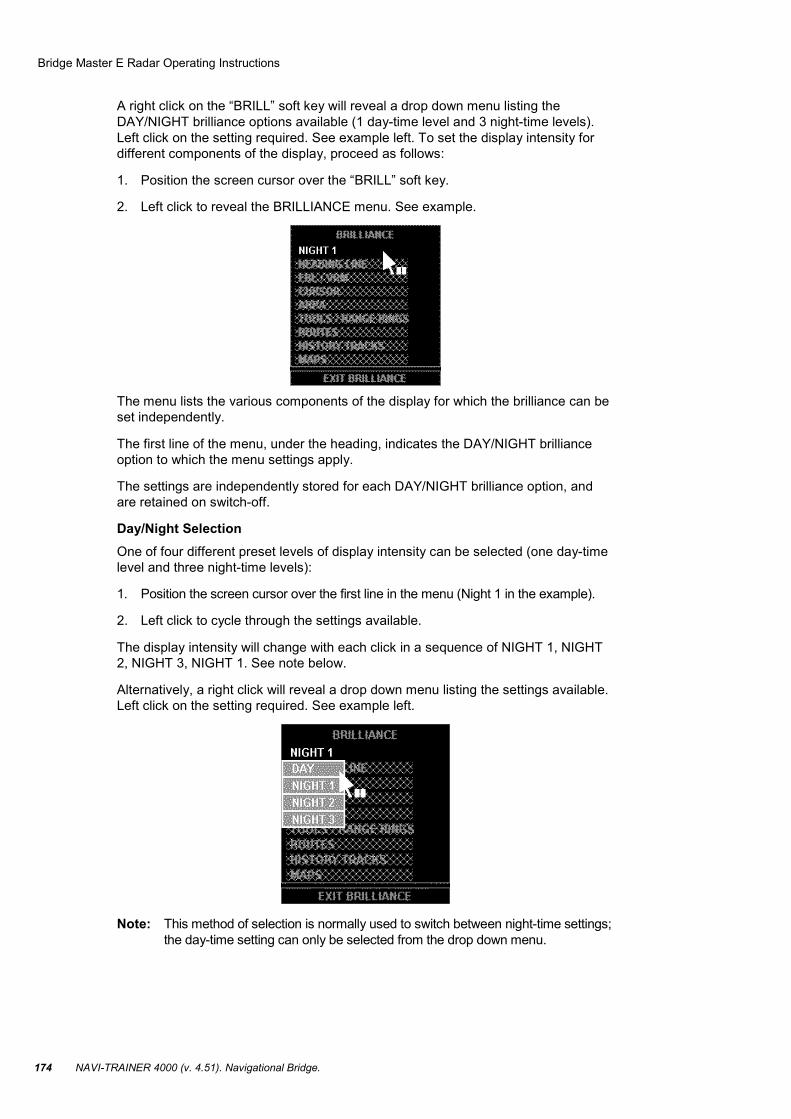
A right click on the “BRILL” soft key will reveal a drop down menu listing the DAY/NIGHT brilliance options available (1 day-time level and 3 night-time levels). Left click on the setting required. See example left. To set the display intensity for different components of the display, proceed as follows:
1. Position the screen cursor over the “BRILL” soft key.
2. Left click to reveal the BRILLIANCE menu. See example.
The menu lists the various components of the display for which the brilliance can be set independently.
The first line of the menu, under the heading, indicates the DAY/NIGHT brilliance option to which the menu settings apply.
The settings are independently stored for each DAY/NIGHT brilliance option, and are retained on switch-off.
Day/Night Selection One of four different preset levels of display intensity can be selected (one day-time level and three night-time levels):
1. Position the screen cursor over the first line in the menu (Night 1 in the example).
2. Left click to cycle through the settings available.
The display intensity will change with each click in a sequence of NIGHT 1, NIGHT 2, NIGHT 3, NIGHT 1. See note below.
Alternatively, a right click will reveal a drop down menu listing the settings available. Left click on the setting required. See example left.
Note: This method of selection is normally used to switch between night-time settings; the day-time setting can only be selected from the drop down menu.
Bridge Master E Radar Operating Instructions
Chapter 5. Transas Radar/Arpa Imitators. 175
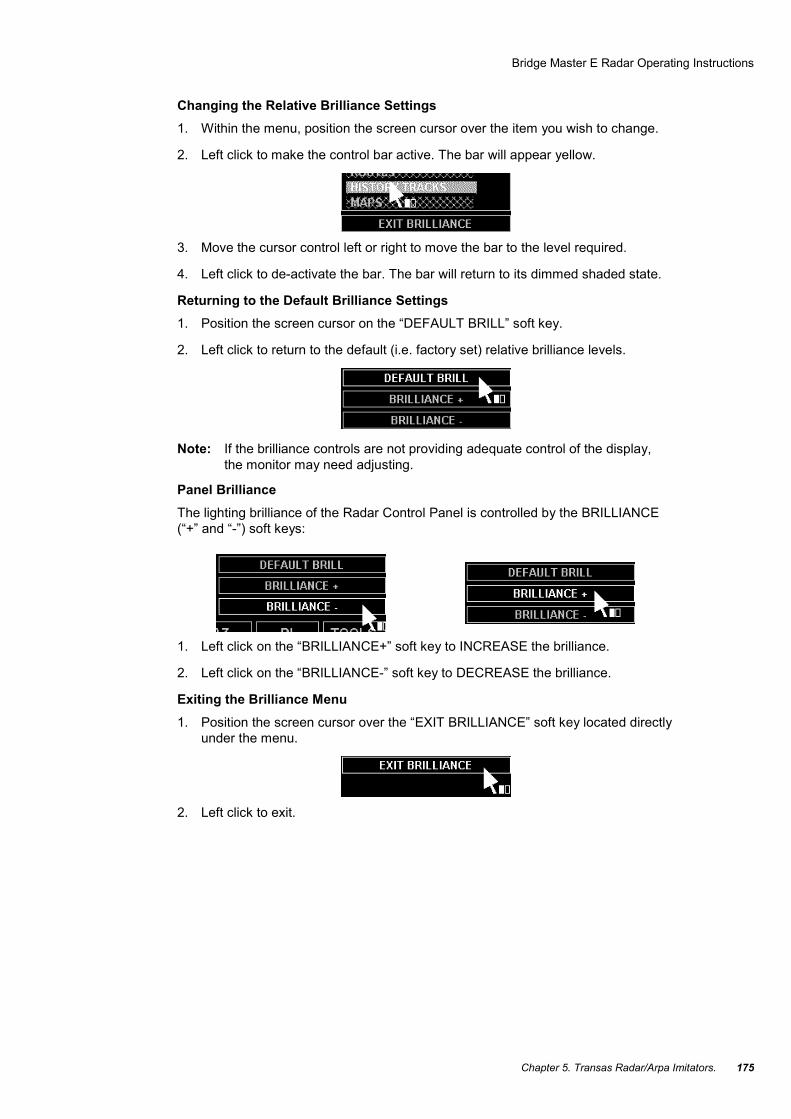
Changing the Relative Brilliance Settings 1. Within the menu, position the screen cursor over the item you wish to change.
2. Left click to make the control bar active. The bar will appear yellow.
3. Move the cursor control left or right to move the bar to the level required.
4. Left click to de-activate the bar. The bar will return to its dimmed shaded state.
Returning to the Default Brilliance Settings 1. Position the screen cursor on the “DEFAULT BRILL” soft key.
2. Left click to return to the default (i.e. factory set) relative brilliance levels.
Note: If the brilliance controls are not providing adequate control of the display, the monitor may need adjusting.
Panel Brilliance The lighting brilliance of the Radar Control Panel is controlled by the BRILLIANCE (“+” and “-”) soft keys:
1. Left click on the “BRILLIANCE+” soft key to INCREASE the brilliance.
2. Left click on the “BRILLIANCE-” soft key to DECREASE the brilliance.
Exiting the Brilliance Menu 1. Position the screen cursor over the “EXIT BRILLIANCE” soft key located directly
under the menu.
2. Left click to exit.

Bridge Master E Radar Operating Instructions
NAVI-TRAINER 4000 (v. 4.51). Navigational Bridge. 176
Returning to Standby Mode The Standby (“STBY”) soft key, located at the top left hand side of the display, is used to return the display to Standby mode:
1. Position the screen cursor over the “STBY” soft key.
2. Left click to go the Standby mode.
Ship’s Heading and Speed
Introduction Ship’s Heading and Speed are displayed in the top right corner of the display and are available in both Standby and Transmit modes.
Heading Display The heading display is divided into three fields.
Bridge Master E Radar Operating Instructions
Chapter 5. Transas Radar/Arpa Imitators. 177
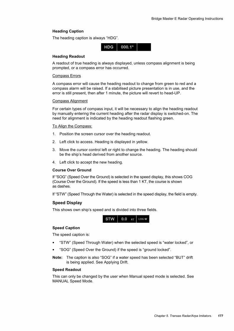
Heading Caption The heading caption is always “HDG”.
Heading Readout A readout of true heading is always displayed, unless compass alignment is being prompted, or a compass error has occurred.
Compass Errors
A compass error will cause the heading readout to change from green to red and a compass alarm will be raised. If a stabilised picture presentation is in use, and the error is still present, then after 1 minute, the picture will revert to head-UP.
Compass Alignment
For certain types of compass input, it will be necessary to align the heading readout by manually entering the current heading after the radar display is switched-on. The need for alignment is indicated by the heading readout flashing green.
To Align the Compass:
1. Position the screen cursor over the heading readout.
2. Left click to access. Heading is displayed in yellow.
3. Move the cursor control left or right to change the heading. The heading should be the ship’s head derived from another source.
4. Left click to accept the new heading.
Course Over Ground If “SOG” (Speed Over the Ground) is selected in the speed display, this shows COG (Course Over the Ground). If the speed is less than 1 KT, the course is shown as dashes.
If “STW” (Speed Through the Water) is selected in the speed display, the field is empty.
Speed Display This shows own ship’s speed and is divided into three fields.
Speed Caption The speed caption is:
• “STW” (Speed Through Water) when the selected speed is “water locked”, or
• “SOG” (Speed Over the Ground) if the speed is “ground locked”.
Note: The caption is also “SOG” if a water speed has been selected “BUT” drift is being applied. See Applying Drift.
Speed Readout This can only be changed by the user when Manual speed mode is selected. See MANUAL Speed Mode.
Bridge Master E Radar Operating Instructions
NAVI-TRAINER 4000 (v. 4.51). Navigational Bridge. 178
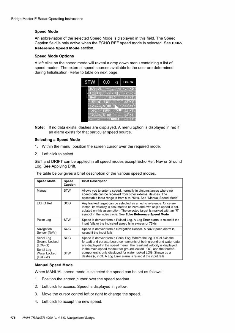
Speed Mode An abbreviation of the selected Speed Mode is displayed in this field. The Speed Caption field is only active when the ECHO REF speed mode is selected. See Echo Reference Speed Mode section.
Speed Mode Options A left click on the speed mode will reveal a drop down menu containing a list of speed modes. The external speed sources available to the user are determined during Initialisation. Refer to table on next page.
Note: If no data exists, dashes are displayed. A menu option is displayed in red if an alarm exists for that particular speed source.
Selecting a Speed Mode 1. Within the menu, position the screen cursor over the required mode.
2. Left click to select.
SET and DRIFT can be applied in all speed modes except Echo Ref, Nav or Ground Log. See Applying Drift.
The table below gives a brief description of the various speed modes.
Speed Mode Speed Caption
Brief Description
Manual STW Allows you to enter a speed, normally in circumstances where no speed data can be received from other external devices. The acceptable input range is from 0 to 75kts. See “Manual Speed Mode”
ECHO Ref SOG Any tracked target can be selected as an echo reference. Once se-lected, its velocity is assumed to be zero and own ship’s speed is cal-culated on this assumption. The selected target Is marked with an “R” symbol in the video circle. See Echo Reference Speed Mode
Pulse Log STW Speed is derived from a Pulsed Log. A Log Error alarm Is raised if the input fails or the indicated speed Is in excess of 75kts
Navigation Sensor (NAV)
SOG Speed is derived from a Navigation Sensor. A Nav Speed alarm is raised if the input fails
Serial Log Ground Locked (LOG-G) Serial Log Water Locked (LOG-W)
SOG STW
Speed is derived from a Serial Log. Where the log is dual axis the fore/aft and port/starboard components of both ground and water data are displayed in the speed menu. The resultant velocity is displayed in the main speed readout for ground locked LOG, and the fore/aft component is only displayed for water locked LOG. Shown as a dashes (-) if off. A Log Error alarm is raised if the input fails
Manual Speed Mode When MANUAL speed mode is selected the speed can be set as follows:
1. Position the screen cursor over the speed readout.
2. Left click to access. Speed is displayed in yellow.
3. Move the cursor control left or right to change the speed.
4. Left click to accept the new speed.

Bridge Master E Radar Operating Instructions
Chapter 5. Transas Radar/Arpa Imitators. 179
Echo Reference Speed Mode Selecting the ECHO REF mode from Speed Caption menu.
Selecting a Target as the Echo Reference:
1. Position the cursor over an established target.
2. Left click to select that target as the echo reference.
“R” is displayed adjacent to the reference target and the target has its true vector removed.
A prompt is displayed if no target is found.
Selecting a New Target as the Echo Reference:
1. Left click on Speed Caption to select Echo Ref mode.
2. Select a new target using the procedure above.
Applying Drift A Set angle and Drift rate, can be applied manually in all but the Echo Ref, Dual-axis Serial Log (ground locked), and Nav speed modes.
From within the drop down menu:
1. Position the screen cursor over the “SET” or “DRIFT” caption.
2. A left click on either caption will reveal a drop down numeric keypad. This keypad includes a “CANCEL” option to replace the “SET” and “DRIFT” values with dashes when not required. If you haven’t used the keypad before.
Drift Applied to Water Speeds
If a water speed has been selected, and a Set and Drift rate have been entered, drift is applied to generate a ground speed and the speed caption changes to SOG. The word “DRIFT” is also displayed in orange under the mode abbreviation in the Speed Mode field.
Any previous values of Set or Drift are automatically cleared on selecting a ground locked log speed, but it is possible to enter new values prior to selecting a water mode.
Note: If the selected speed input is a dual-axis log, the SOG is calculated using the SET& DRIFT and both fore/aft and port/starboard components of the log input.
Bridge Master E Radar Operating Instructions
NAVI-TRAINER 4000 (v. 4.51). Navigational Bridge. 180
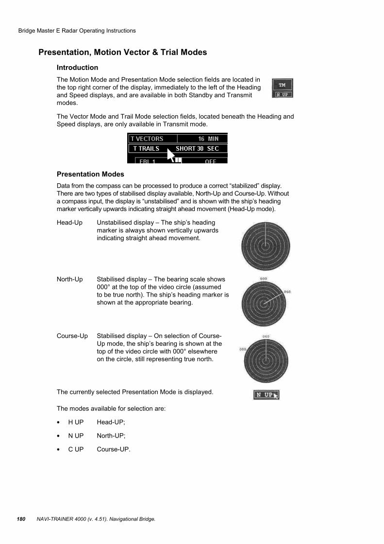
Presentation, Motion Vector & Trial Modes Introduction The Motion Mode and Presentation Mode selection fields are located in the top right corner of the display, immediately to the left of the Heading and Speed displays, and are available in both Standby and Transmit modes.
The Vector Mode and Trail Mode selection fields, located beneath the Heading and Speed displays, are only available in Transmit mode.
Presentation Modes Data from the compass can be processed to produce a correct “stabilized” display. There are two types of stabilised display available, North-Up and Course-Up. Without a compass input, the display is “unstabilised” and is shown with the ship’s heading marker vertically upwards indicating straight ahead movement (Head-Up mode).
Head-Up Unstabilised display – The ship’s heading marker is always shown vertically upwards indicating straight ahead movement.
North-Up Stabilised display – The bearing scale shows 000° at the top of the video circle (assumed to be true north). The ship’s heading marker is shown at the appropriate bearing.
Course-Up Stabilised display – On selection of Course-Up mode, the ship’s bearing is shown at the top of the video circle with 000° elsewhere on the circle, still representing true north.
The currently selected Presentation Mode is displayed.
The modes available for selection are:
• H UP Head-UP;
• N UP North-UP;
• C UP Course-UP.

Bridge Master E Radar Operating Instructions
Chapter 5. Transas Radar/Arpa Imitators. 181
Selecting a Presentation Mode Either
1. Position the screen cursor over the Presentation Mode field.
2. Left click consecutively to toggle through the available options.
Note: If H UP is the currently selected mode, the first left click will select the N UP mode. Subsequent left clicks will then toggle between the C UP and N UP options only. This prevents the accidental selection of an unstabilised mode while in a stabilised mode. To select the H UP mode use the method described below.
or
1. Position the screen cursor over the Presentation Mode field.
2. Right click to reveal a drop down menu.
3. Position the screen cursor over the required mode.
4. Left click to select.
Course-UP Reset When the C UP mode is in operation, if the ship alters course, a Course-Up reset should be performed by reselecting the mode. This realigns the bearing scale to bring the new course to the top of the video circle, i.e. it doesn’t happen automatically as the ship changes course.
Motion Modes The motion mode determines whether own ship moves across the radar picture or remains at a selected point, and how the trails of moving targets are displayed.
The currently selected Motion Mode is displayed.
The modes available for selection are:
• RM(R) Relative Motion – Relative Trails;
• TM True Motion.
In Relative Motion – Relative Trails, own ship is displayed at a fixed point in the video circle (normally the centre) and all target trails are shown relative to own ship’s movement. This means that stationary targets will have trails if own ship is moving.
In True Motion, own ship moves across the video circle. Stationary targets, therefore, don’t produce any trails.

Bridge Master E Radar Operating Instructions
NAVI-TRAINER 4000 (v. 4.51). Navigational Bridge. 182
Selecting a Motion Mode
Note: If the radar is in unstabilised (Head-Up) mode, only relative motion will be available.
Either:
1. Position the screen cursor over the Motion Mode field.
2. Left click consecutively to toggle through the available options.
or
1. Position the screen cursor over the Motion Mode field.
2. Right click to reveal a drop down menu.
3. Within the menu the current selection is highlighted, position the screen cursor over the required mode.
4. Left click to select.
Vector Modes Vectors are shown on the radar display to indicate the velocity (speed and direction) of own ship and moving targets. The length of the vector indicates speed and its bearing indicates direction.
This function is only available in Transmit mode and is not displayed in Standby.
The Vector selection box is divided into two fields as illustrated below. The currently selected mode is displayed.
The vector mode determines whether the vectors represent the true velocity of targets or their velocity relative to own ship.
True Vectors All moving targets and own ship have a vector representing their movement (speed and direction) over the water/ground.
Relative Vectors If own ship is moving, all targets, moving and stationary, have a vector representing their movement (speed and direction) relative to own ship. Own ship will not have a vector in this mode.
Selecting a Vector Mode A TRUE or REL (Relative) Vector mode can be selected as follows:
1. Position the screen cursor over the Vector mode selection field.
2. Consecutive left clicks will toggle the mode between TRUE (T) and RELATIVE (R) vectors.

Bridge Master E Radar Operating Instructions
Chapter 5. Transas Radar/Arpa Imitators. 183
Note: If Vector Timeout has been selected (ARPA/LIMITS & SETTINGS menu) then the vector mode will revert to the same as the motion mode after 30 seconds.
Selecting a Vector Time The “vector time” selected will determine the length of the vectors shown on the radar display. The length of a vector represents the distance the ship/target will travel in the “vector time”, for example:
• Vector Time =5 min;
• Speed (of ship/target) =12 kt;
• Length of Vector =1 nm.
The optimum vector time will depend on the range scale in use.
The Vector Time can be adjusted as follows:
1. Position the screen cursor over the vector time field.
2. Left click to access.
3. Move the cursor control left or right to change the time.
4. Left click to accept.
Alternatively a right click will reveal a drop down numeric keypad from which the vector time can be entered.
Extending the vector time lets you check on CPAs of targets by projecting their movements further into the future.
Trails Mode Decaying video trails, showing the history of a target’s movements, can be displayed in addition to the target vectors. The manner in which the trails are displayed depends on the motion mode in use. In Relative Motion – Relative Trails (RM(R)) the trails indicate the movement of the targets relative to own ship. In True Motion and Relative Motion – True Trails (TM and RM(T)), the trails have own ship’s speed applied, and show movement over the ground if selected speed is ground locked, or through the water if the speed is water locked.
The Trail function is only available in Transmit Mode and will not be displayed in Standby.
When True Motion or Relative Motion – True Trails (TM or RM(T)) is selected the letter “T” (True Trails) is displayed at the LH side of the text in the Trails display field, otherwise “R” (Relative Trails) is displayed, see below.

Bridge Master E Radar Operating Instructions
NAVI-TRAINER 4000 (v. 4.51). Navigational Bridge. 184
Trail Time This shows the length of the trails. If the trails have not yet built up to their maximum length, a count-up time is shown indicating how long they have been building up.
Selecting a Trails Mode
A left click reveals a drop down menu containing the trail modes available. The currently selected mode is highlighted. The options available for selection are as follows:
• “SHORT” – high rate of decay giving a short trail. Actual trail length will depend on the range in use, see table below;
• “LONG” – low rate of decay giving a long trail. Actual trail length will depend on the range in use, see table below;
• “PERM” – permanent trail which does not decay. When the trail length becomes greater than 99 minutes it is indicated as “PERM”;
• “OFF” – trails removed from display;
• “RESET” – keeps the currently selected mode, but resets counter and clears the video.
Within the menu, position the screen cursor over the required mode.
Left click to select.
By pressing the right mouse button you can at any time remove the target trails from the screen and then restore the trails with another right mouse button click.
The selection of LONG or SHORT alters the speed of decay of the trails and is dependant on the range scale in use. In the table below the times given indicate the length of the trail as displayed on the screen. Trails default to SHORT after power up.
Range Scale (nm) Short Time LONG Time
0.125 10s 30s
0.25 10s 30s
0.5 15s 45s
0.75 15s 45s
1.5 30s 90s
3.0 30s 90s
6,0 and above 1 min 3 min
Warning Prompts Presentation Mode Warnings If an attempt is made to enter a stabilised presentation mode when the compass is on alarm, the following prompt is displayed.

Bridge Master E Radar Operating Instructions
Chapter 5. Transas Radar/Arpa Imitators. 185
EBLs, ERBLs and VRMs
Introduction Two EBLs (Electronic Bearing Lines) and two VRMs (Variable Range Markers) are available and can be displayed simultaneously in the video circle. They are available in both Standby and Transmit modes.
“VRM 1” is always associated with “EBL 1” and “VRM 2” with “EBL 2”. Both VRMs and EBLs default to “OFF”.
In Standby mode, ranges and bearings are measured relative to the centre of the video circle rather than own ship. When switching between Standby and Transmit modes all EBLs and VRMs are turned OFF.
The range and bearing values (displayed to the right of the VRM and EBL caption boxes) are only displayed when the associated VRM or EBL is ON.
If an EBL is turned ON while its associated VRM is turned OFF, then the EBL is displayed as an ERBL (Electronic Range and Bearing Line).
Electronic Bearing Line (EBL) EBLs can be turned ON or OFF independently. Any settings are remembered when they are switched OFF.

Bridge Master E Radar Operating Instructions
NAVI-TRAINER 4000 (v. 4.51). Navigational Bridge. 186
Turning EBLs ON and OFF 1. Position the screen cursor over the EBL caption box.
2. Left click to toggle ON or OFF.
An EBL is displayed as a green line in the video circle.
If an EBL is turned ON while its associated VRM is turned OFF, then the EBL is displayed as an ERBL with a small circle positioned on the bearing line to indicate the range (providing it is within the range of the video circle).
Changing the Bearing of an EBL or ERBL 1. Position the screen cursor over the bearing.
2. Left click to access.
3. Move the cursor control left or right to change the bearing.
4. Left click to accept.
Alternatively a right click will reveal a drop down numeric keypad from which the bearing can be entered.
The range of an ERBL can be changed in the same way.
Depending on the presentation mode selected, the letter T is displayed to indicate a true bearing or the letter R for relative.
Direct ERBL Control To control the range and bearing of an ERBL from within the video circle:
1. Position the screen cursor (+) over the small VRM circle on the EBL.
2. Press and hold down the left key.
3. Move the cursor control in any direction to change the ERBL settings.
4. Release the key to accept.
Note: If the small VRM circle is over a target, a single key click is associated with that target. It is therefore essential to keep the left key pressed when changing the ERBL settings.
Variable Range Marker (VRM) The two VRMs can be turned ON or OFF independently. Any settings are remembered when they are switched OFF.
Turning VRMs ON and OFF 1. Position the screen cursor over the VRM caption box.
2. Left click to toggle ON or OFF.

Bridge Master E Radar Operating Instructions
Chapter 5. Transas Radar/Arpa Imitators. 187
A VRM 1 is displayed as a green ring and a VRM 2 is displayed as a red ring in the video circle.
Changing the Range of a VRM 1. Position the screen cursor over the range.
2. Left click to access.
3. Move the cursor control left or right to change the range.
4. Left click to accept.
Alternatively a right click will reveal a drop down numeric keypad from which the range can be entered.
Combined VRM and EBL Control To control a VRM and it’s associated EBL from within the video circle:
1. Position the screen cursor (“+”) over the intersection of the VRM and EBL.
2. Press and hold down the left key.
3. Move cursor control in any direction to change the range and bearing.
4. Release the key to accept.
Note: If the intersection of an EBL and its associated VRM is over a target, a single key click is associated with that target. It is therefore essential to keep the left key pressed when changing the VRM and EBL.

Bridge Master E Radar Operating Instructions
NAVI-TRAINER 4000 (v. 4.51). Navigational Bridge. 188
Options “EBL2” can be either centred or off-centred (“EBL 1”/“VRM 1” can only be centred). When centred, EBL 2 are displayed with origin at own ship.
To select the required option (For “EBL 2” ONLY) “EBL 2” must be ON.
1. Position the screen cursor over the “EBL 2” caption box.
2. Right click to reveal the drop down menu.
3. Move the screen cursor to the required option. If “OFFCENTRE” is selected the screen cursor is re-positioned at the video circle: – move the cursor (“+”) to the required off-centre location;
– left click to select; the EBL/VRM is redrawn at the new position.
Defaults If the video circle is in a stabilised display mode, the bearing of EBLs is true (i.e. with respect to true north), if unstabilised the bearing is relative to own ship’s heading line. Switching between stabilised and unstabilised modes causes both EBLs to revert to their default values. They are also turned OFF if previously set to ON.
The default bearing for EBL 1 is 5.0° and for EBL 2, 355°. The default range for VRM 1 is 2.5 nm and for VRM 2, 4.5 nm.
Target Functions
Bridge Master E Radar Operating Instructions
Chapter 5. Transas Radar/Arpa Imitators. 189
Introduction In transmit mode, any target that appears on the radar display within 40 nm can be tracked. The method used is target acquisition and auto-tracking. Once a target has been acquired, information relating to the target’s proximity to own ship and its speed and bearing is maintained until the target is “cancelled”.
Information on one or more tracked targets can be displayed in a target box – see Target Data later in this chapter.
Manual Acquisition of Targets Manual acquisition is only available on range scales of 0.25 nm and above. When a target is acquired it is automatically assigned an identification number. Target numbering always starts at I and goes up to a maximum of 40. A target is assigned the next number in the sequence. Gaps which occur due to targets being cancelled or dropped, are not filled until the maximum number has been reached.
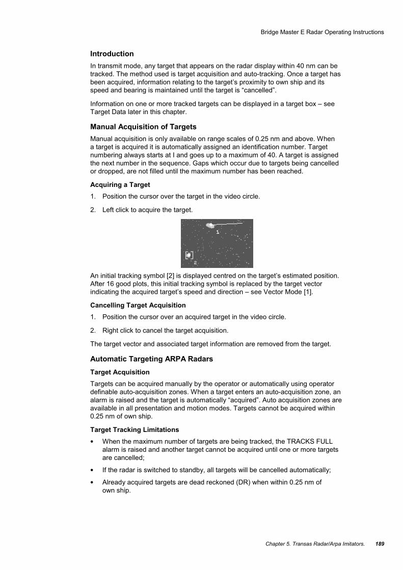
Acquiring a Target 1. Position the cursor over the target in the video circle.
2. Left click to acquire the target.
An initial tracking symbol [2] is displayed centred on the target’s estimated position. After 16 good plots, this initial tracking symbol is replaced by the target vector indicating the acquired target’s speed and direction – see Vector Mode [1].
Cancelling Target Acquisition 1. Position the cursor over an acquired target in the video circle.
2. Right click to cancel the target acquisition.
The target vector and associated target information are removed from the target.
Automatic Targeting ARPA Radars Target Acquisition Targets can be acquired manually by the operator or automatically using operator definable auto-acquisition zones. When a target enters an auto-acquisition zone, an alarm is raised and the target is automatically “acquired”. Auto acquisition zones are available in all presentation and motion modes. Targets cannot be acquired within 0.25 nm of own ship.
Target Tracking Limitations • When the maximum number of targets are being tracked, the TRACKS FULL
alarm is raised and another target cannot be acquired until one or more targets are cancelled;
• If the radar is switched to standby, all targets will be cancelled automatically;
• Already acquired targets are dead reckoned (DR) when within 0.25 nm of own ship.

Bridge Master E Radar Operating Instructions
NAVI-TRAINER 4000 (v. 4.51). Navigational Bridge. 190
The integrity of ARPA tracking is a function of many variables which include clutter conditions, signal-to-noise ratio and sensor errors (log, compass, nav input etc.). The design of the tracker minimises the effects of these errors but the operator must be aware that such errors will produce discrepancies in derived tracked target information such as true speed, course, bearing, CPA and TCPA.
The possibility of target swop is minimised by the use of damped plot predictions in the tracker. The ARPA tracker employs advanced rain and sea clutter rejection techniques independent of the display settings. A fully established tracked target will not be affected by large levels of sea or rain clutter, however attempting to acquire a target at close range in severe clutter conditions, may cause the occasional appearance of the lost target symbol and its associated alarm.
When changing from one speed mode to another, and particularly between a water speed and a ground speed mode, the vectors take some time to resettle. Three minutes should be allowed to obtain full accuracy when switching between speed modes.
Compass Errors If targets are being tracked, a compass error will cause affected target tote data to change from green to red. The affected data being TBRG, CPA, TCPA, COG (or CSE), SOG (or STW), BCR and BCT. After 1 minute all tracked targets will be cancelled; auto acquisition zones, mapping facilities, the constant radius turn and plots will be switched off and it will not be possible to use these facilities, or select a stabilised mode, until a valid compass heading is available. The system will reset to the H-Up presentation mode.
Target Alarm Symbols If an alarm is raised against a target currently in the video circle, an alarm symbol is displayed. This symbol flashes until the alarm is acknowledged. The alarm symbol then remains displayed as long as the alarm condition exists.
Even if the target is not currently displayed in the video circle, an alarm will still be raised. An unacknowledged alarm always has a higher priority than an acknowledged alarm. The following alarm symbols, listed in order of priority, are used:
• if the radar hasn’t been able to obtain successfully the position of a target, which is being used as an echo reference, during the last three radar scans, a LOST REF alarm is raised;
◊
• if an acquired target infringes the bow crossing limits, a BOW CROSSING alarm is raised;
╬
• if an acquired target infringes the CPA and TCPA limits, a CPA/TCPA alarm is raised;
△
• when a target enters an auto-acquisition zone, an AZ ENTRY alarm is raised; ▽
• if the radar hasn’t been able to obtain successfully a target’s position during the last six radar scans, a LOST TARGET alarm is raised.
◊
Bridge Master E Radar Operating Instructions
Chapter 5. Transas Radar/Arpa Imitators. 191
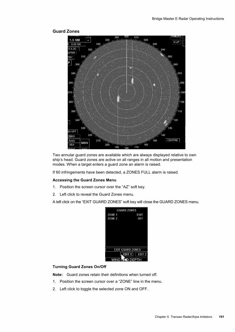
Guard Zones
Two annular guard zones are available which are always displayed relative to own ship’s head. Guard zones are active on all ranges in all motion and presentation modes. When a target enters a guard zone an alarm is raised.
If 60 infringements have been detected, a ZONES FULL alarm is raised.
Accessing the Guard Zones Menu 1. Position the screen cursor over the “AZ” soft key.
2. Left click to reveal the Guard Zones menu.
A left click on the “EXIT GUARD ZONES” soft key will close the GUARD ZONES menu.
Turning Guard Zones On/Off
Note: Guard zones retain their definitions when turned off.
1. Position the screen cursor over a “ZONE” line in the menu.
2. Left click to toggle the selected zone ON and OFF.

Bridge Master E Radar Operating Instructions
NAVI-TRAINER 4000 (v. 4.51). Navigational Bridge. 192
Defining a Guard Zone
Note: A guard zone is not active while it is being defined.
1. Position the cursor over an “EDIT” soft key.
2. Left click to select edit mode for the associated guard zone.
3. Move the cursor to the centre of the video circle from where the zone can be edited. The other zone will temporarily be displayed at its last setting for reference purposes (provided the range in use is suitable), but will not detect any infringements unless it is currently ON. The selected zone is displayed in a different colour and the associated ZONE ON/OFF line in the menu shows EDIT.
4. Edit the zone as described in Annular Zone Editing later in this chapter.
5. Select another soft key (EDIT or EXIT GUARD ZONES) to store the new zone and automatically switch it on.
Annular Zone Editing Changing the Start/Stop Bearing 1. Position the cursor over the start or stop bearing as required.
2. Press and hold down the left key.
3. Drag the start or stop bearing to its new position.
4. Release the key.
Changing the Range of a Zone 1. Place the cursor over the inner arc of the annulus.
2. Press and hold down the left key.
3. Drag the entire zone to its new position.
4. Release the key.
Altering the Depth of the Zone 1. Place the cursor over the outer arc of the annulus.
2. Press and hold down the left key.
3. Drag the outer arc to its new position.
4. Release the key.
Target Data The target box defaults to showing data for a single target.
Acquired Target Data The following data is shown:
Bridge Master E Radar Operating Instructions
Chapter 5. Transas Radar/Arpa Imitators. 193
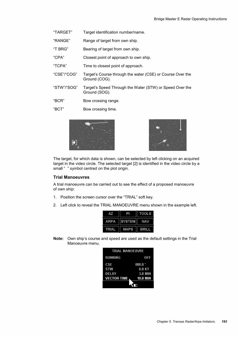
“TARGET” Target identification number/name.
“RANGE” Range of target from own ship.
“T BRG” Bearing of target from own ship.
“CPA” Closest point of approach to own ship.
“TCPA” Time to closest point of approach.
“CSE”/“COG” Target’s Course through the water (CSE) or Course Over the Ground (COG).
“STW”/“SOG” Target’s Speed Through the Water (STW) or Speed Over the Ground (SOG).
“BCR” Bow crossing range.
“BCT” Bow crossing time.
The target, for which data is shown, can be selected by left clicking on an acquired target in the video circle. The selected target [2] is identified in the video circle by a small “ ” symbol centred on the plot origin.
Trial Manoeuvres A trial manoeuvre can be carried out to see the effect of a proposed manoeuvre of own ship:
1. Position the screen cursor over the “TRIAL” soft key.
2. Left click to reveal the TRIAL MANOEUVRE menu shown in the example left.
Note: Own ship’s course and speed are used as the default settings in the Trial Manoeuvre menu.

Bridge Master E Radar Operating Instructions
NAVI-TRAINER 4000 (v. 4.51). Navigational Bridge. 194
Running a Trial Manoeuvre Final Course of Own Ship
Enter the proposed course of own ship to be followed after the manoeuvre:
1. Left click on the course line (CSE in the example) to activate.
2. Move the cursor control left or right to set the course required.
3. Left click to accept.
Speed of Manoeuvre
If you intend to change speed, enter the proposed speed of own ship to be maintained during and after the manoeuvre:
1. Left click on the speed line (STW in the example) to activate.
2. Move the cursor control left or right to set the required speed.
3. Left click to accept.
Manoeuvre Delay
Enter the proposed time delay between switching the trial manoeuvre ON and actually starting the manoeuvre:
1. Left click on the DELAY line to activate.
2. Move the cursor control left or right to set the required delay.
3. Left click to accept.
Vector Type
Select TRUE or REL (Relative) vector type as follows:
1. Position the screen cursor over the vector type selection field in the Trial Manoeuvre menu.
2. Consecutive left clicks will toggle the type between TRUE (T) and RELATIVE (R) VECTORS.
Vector Time
Enter the proposed vector time:
1. Position the screen cursor over the vector time field in the Trial Manoeuvre menu.
2. Left click to access.
3. Move the cursor control left or right to change the time.
4. Left click to accept.
Note: Entering a longer vector time will allow you to see further into the trial manoeuvre. The above procedures (for Vector Type and Vector Time) will overwrite any selections made earlier (see Vector Node) and will remain in force until changed. If required, reset the vector time after the trial manoeuvre is completed.

Bridge Master E Radar Operating Instructions
Chapter 5. Transas Radar/Arpa Imitators. 195
Manoeuvre Switch-ON
Left click on the RUNNING OFF line to switch the manoeuvre ON. The “manoeuvre delay” entered earlier will start to count down.
The manoeuvre vectors are displayed until the time for the manoeuvre expires, or the manoeuvre is switched-OFF. (When the manoeuvre is running, a left click on the RUNNING ON line will switch-OFF the manoeuvre.)
The trial manoeuvre vectors are displayed when the trial manoeuvre is running.
If true (T) vectors are selected, the trial vector is shown for own ship only, as shown in the example below. This shows own ship’s true course during the manoeuvre.
If relative (R) vectors are selected, the trial vectors are applied to every, acquired target, with own ship’s vector suppressed, and show the course of the targets relative to own ship.
Note: “Vector type” (T or R vectors) and “vector time” may be changed at any time before or during the manoeuvre.
While the trial manoeuvre is running and the Trial Manoeuvre Menu is displayed, the word “TRIAL” will appear at the bottom of the video circle. Once the delay has elapsed, the word “TRIAL” is removed from the display and the manoeuvre is turned OFF.
Note: A MVR TIME alarm is raised 30 seconds before the manoeuvre is turned OFF.
Exit from TRIAL MANOEUVRE Menu To exit from TRIAL MANOEUVRE menu, click the right mouse button on TRIAL soft key.
Display of UAIS Information Display of UAIS Targets With the arrival of data from the UAIS transponder, information on targets appears on the radar display.

Bridge Master E Radar Operating Instructions
NAVI-TRAINER 4000 (v. 4.51). Navigational Bridge. 196
With the first appearance of information, a UAIS target is shown as an acute-angled triangle (sleeping UAIS).
To acquire a UAIS target for tracking, position the cursor on the target mark and click the left trackball/mouse button. The tracked UAIS target will be shown as an acute-angled triangle with the relative bearing line.
If a UAIS target is on the turning circle, the tip of the heading line will show the turn direction.
COG/SOG vector is shown as a dashed line originating from the centre of the triangle.
UAIS targets can be acquired automatically if they are within the guard zone or if they are dangerous targets (by CPA\TCPA criterion). In this case, UAIS targets are shown as red coloured marks flickering with a frequency of 1 Hz.

Bridge Master E Radar Operating Instructions
Chapter 5. Transas Radar/Arpa Imitators. 197
In the case of lost tracking (data stops arriving), after some time the UAIS will be displayed in the form of a blue coloured crossed triangle.
Obtaining UAIS Data To obtain data on a UAIS target, position the cursor on the target mark and click the left trackball/mouse button. The Targets panel will display information on the acquired target.
The triangle next to the target number will indicate availability of data from the UAIS transponder. The target’s course and speed will be shown from the UAIS data.
To display additional UAIS information, position the cursor on the panel and click the left trackball/mouse button. The screen will display additional UAIS information.
Additional UAIS information panel will contain the following lines:
“MMSI” Target’s MMSI.
“HEADING” Heading.
Navigational status. “TYPE” Ship type (as per the standard classification).
“IMO NUM” IMO number. “CALL SIGN” Target callsign.
Ship name.
Port of destination.

Bridge Master E Radar Operating Instructions
NAVI-TRAINER 4000 (v. 4.51). Navigational Bridge. 198
ARPA Functions
Introduction As the radar is configured as an ARPA, a large range of additional target related functions can be provided. Access to these functions is via the programmable ARPA key.
Accessing ARPA Functions 1. Position the screen cursor over the “ARPA” soft key.
2. Right click to toggle ARPA data display ON or OFF.
Note: When the ARPA function is turned-ON, only the options currently ON in the ARPA menu will be visible. When turned-OFF all ARPA related synthetics are removed from the radar picture.
A left click will reveal the ARPA menu.
Bridge Master E Radar Operating Instructions
Chapter 5. Transas Radar/Arpa Imitators. 199
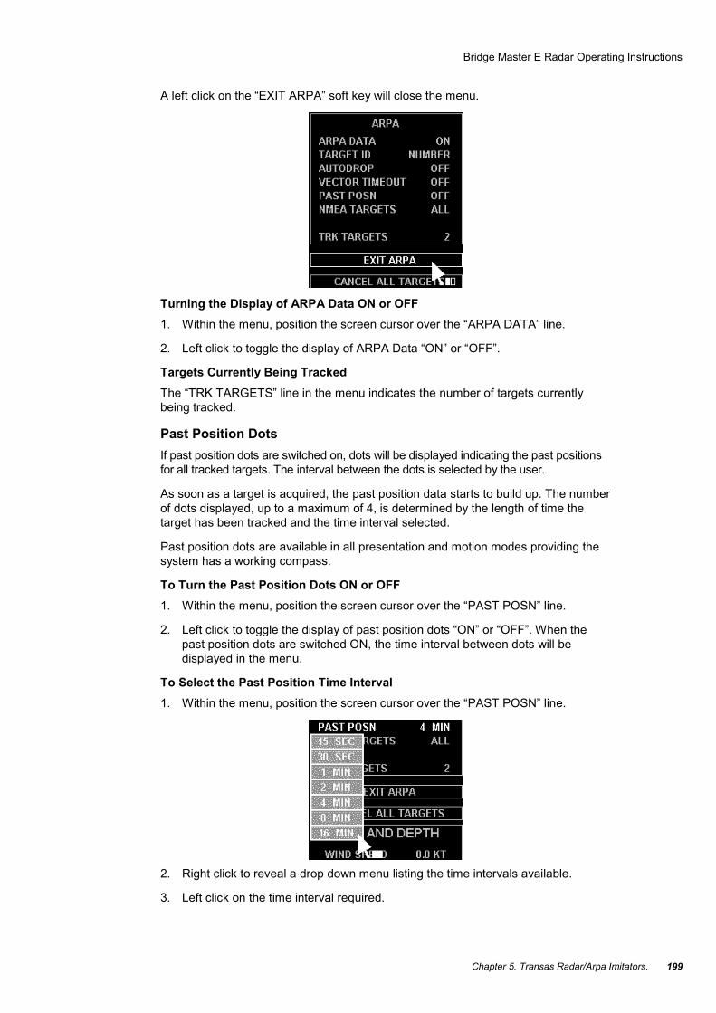
A left click on the “EXIT ARPA” soft key will close the menu.
Turning the Display of ARPA Data ON or OFF 1. Within the menu, position the screen cursor over the “ARPA DATA” line.
2. Left click to toggle the display of ARPA Data “ON” or “OFF”.
Targets Currently Being Tracked The “TRK TARGETS” line in the menu indicates the number of targets currently being tracked.
Past Position Dots If past position dots are switched on, dots will be displayed indicating the past positions for all tracked targets. The interval between the dots is selected by the user.
As soon as a target is acquired, the past position data starts to build up. The number of dots displayed, up to a maximum of 4, is determined by the length of time the target has been tracked and the time interval selected.
Past position dots are available in all presentation and motion modes providing the system has a working compass.
To Turn the Past Position Dots ON or OFF 1. Within the menu, position the screen cursor over the “PAST POSN” line.
2. Left click to toggle the display of past position dots “ON” or “OFF”. When the past position dots are switched ON, the time interval between dots will be displayed in the menu.
To Select the Past Position Time Interval 1. Within the menu, position the screen cursor over the “PAST POSN” line.
2. Right click to reveal a drop down menu listing the time intervals available.
3. Left click on the time interval required.

Bridge Master E Radar Operating Instructions
NAVI-TRAINER 4000 (v. 4.51). Navigational Bridge. 200
Target IDs This facility enables the operator to select whether target IDs are displayed in the video circle against the associated tracked targets.
To Turn on the Display of Target Identifiers 1. Within the menu, position the screen cursor over the “TARGET ID” line.
2. Left click to toggle through the options available, i.e. OFF – Number.
or
3. Within the menu, position the screen cursor over the “TARGET ID” line.
4. Right click to reveal a drop down menu.
5. Left click on the option to be displayed, or on “OFF” to turn the display off.
Automatic Dropping of Targets If Autodrop mode is switched on, targets which are not a danger to own ship are automatically dropped without any alarm being raised.
Any target, whether it was acquired manually or automatically, will be dropped if it meets all of the following criteria:
• the target is not in an auto-acquisition zone;
• it is not the echo reference target;
• it doesn’t have a CPA/TCPA or Bow Crossing alarm raised against it;

Bridge Master E Radar Operating Instructions
Chapter 5. Transas Radar/Arpa Imitators. 201
• the TCPA is more than 3 minutes ago;
• the target is astern of own ship;
• its range is more than 10 nm from own ship.
Regardless of whether Autodrop mode is ON or OFF, all targets will be dropped when the radar is switched to standby. Also, any target which meets any of the following criteria will be automatically dropped without an alarm being raised:
• its range is more than 40 nm. from own ship;
• valid plot data has not been obtained for the last 60 radar scans, i.e. the target has been lost.
Autodrop 1. Click the left mouse button on LIMITS & SETTING line in ARPA menu:
the screen will display a menu with the same name.
2. The Autodrop facility is selected (ON or OFF) by a left click on the “AUTODROP” line in the menu.
Vector Timeout If the selected vector mode does not match the current motion mode, the vector data is displayed in orange. If Vector Timeout has been selected (ON) using the procedure below, then the vector mode will revert to the same as the motion mode after 30 seconds.
To Turn Vector Timeout ON or OFF 1. Within the LIMITS & SETTING menu, position the screen cursor over the
“VECTOR TIMEOUT” line.
2. Left click to toggle for “ON” or “OFF”.
NMEA Targets The facility is provided to output data on tracked targets. The output data conforms to the NMEA 0183 standard. Data is output on all tracked targets provided that Track Table O/P has been selected under initialization:
1. Position the screen cursor on NMEA TARGETS line in LIMITS & SETTING menu.
2. Left mouse clicks switch between the display of data on all targets (ALL) or (MULTI) targets.
or
3. Position the screen cursor on NMEA TARGETS line in LIMITS & SETTING menu.
4. Click the right mouse button to display a drop down menu on the screen.
5. Click the left mouse button either on ALL if you wish to obtain data on all the tracked targets, or on MULTI TARGET.
Bridge Master E Radar Operating Instructions
NAVI-TRAINER 4000 (v. 4.51). Navigational Bridge. 202
Limits of Targets Maximum Approach Point and Bow Crossing Parameters Limits of CPA/TCPA and BCR/BCT can be change in the following way:
1. Position the screen cursor on CPA LIMIT, TCPA LIMIT, BCR LIMIT or BCT LIMIT line in LIMITS & SETTING menu.
2. Click the left mouse button to activate it.
3. Move the cursor to the left or to the right until the required CPA/TCPA and BCR/BCT limit value is obtained.
Click the left mouse button to record the selected value.
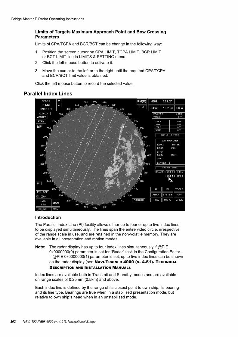
Parallel Index Lines
Introduction The Parallel Index Line (PI) facility allows either up to four or up to five index lines to be displayed simultaneously. The lines span the entire video circle, irrespective of the range scale in use, and are retained in the non-volatile memory. They are available in all presentation and motion modes.
Note: The radar display has up to four index lines simultaneously if @PIE 0x0000000(0) parameter is set for “Radar” task in the Configuration Editor. If @PIE 0x0000000(1) parameter is set, up to five index lines can be shown on the radar display (see NAVI-TRAINER 4000 (V. 4.51). TECHNICAL
DESCRIPTION AND INSTALLATION MANUAL).
Index lines are available both in Transmit and Standby modes and are available on range scales of 0.25 nm (0.5km) and above.
Each index line is defined by the range of its closest point to own ship, its bearing and its line type. Bearings are true when in a stabilised presentation mode, but relative to own ship’s head when in an unstabilised mode.

Bridge Master E Radar Operating Instructions
Chapter 5. Transas Radar/Arpa Imitators. 203
Accessing the Edit Index Lines Menu 1. Position the screen cursor over the “PI” soft key which is located in the bottom
right corner of the display.
2. Left click to reveal the Edit Index Lines menu.
When the EDIT INDEX LINES menu is displayed it overwrites the target data and user data areas, and presents a new set of soft keys.
Note: A left click on the EXIT EDIT LINES soft key will close the menu.
Index Line Editing Within the EDIT INDEX LINES menu, all lines are used for editing, but are not active until edit mode is selected.
A defined line will be shown at its last position. If not yet defined it will default to the bearing of any other defined line. If it is the first line to be defined it will be shown as a horizontal line through the centre of the video circle.
Bridge Master E Radar Operating Instructions
NAVI-TRAINER 4000 (v. 4.51). Navigational Bridge. 204
Selecting the EDIT Mode 1. Position the screen cursor over one of programmable LINE 1…LINE 4 keys
located under the EDIT INDEX LINES menu, thus selecting the line which should be edited.
2. Left click to access. The menu will show the name of the line which is being edited (e.g. EDIT LINE 3).
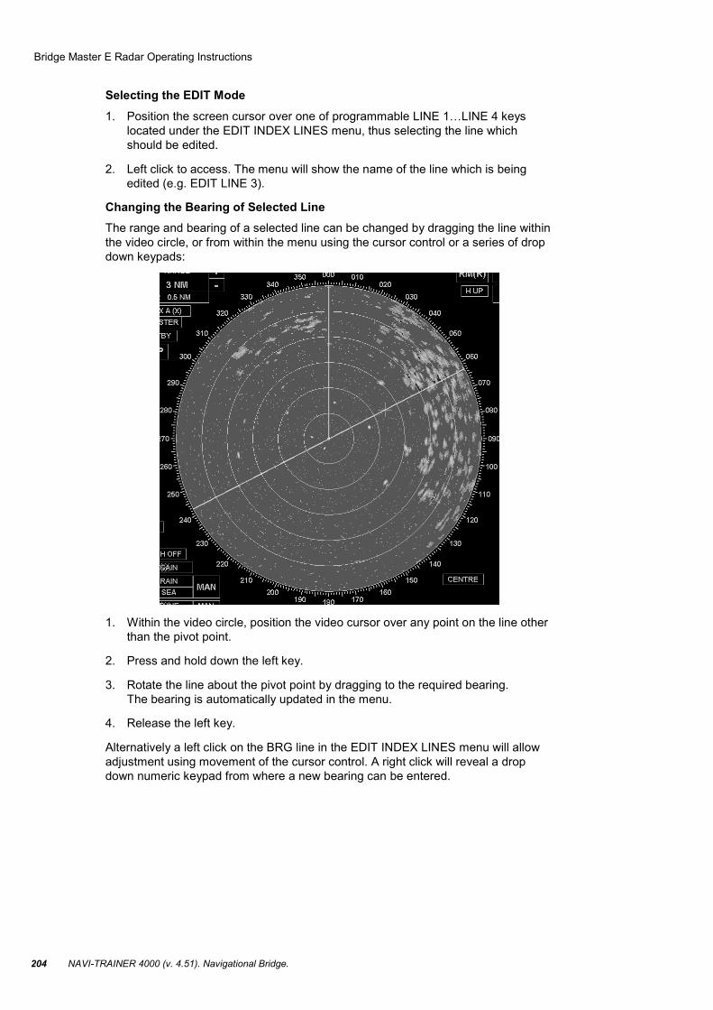
Changing the Bearing of Selected Line The range and bearing of a selected line can be changed by dragging the line within the video circle, or from within the menu using the cursor control or a series of drop down keypads:
1. Within the video circle, position the video cursor over any point on the line other than the pivot point.
2. Press and hold down the left key.
3. Rotate the line about the pivot point by dragging to the required bearing. The bearing is automatically updated in the menu.
4. Release the left key.
Alternatively a left click on the BRG line in the EDIT INDEX LINES menu will allow adjustment using movement of the cursor control. A right click will reveal a drop down numeric keypad from where a new bearing can be entered.

Bridge Master E Radar Operating Instructions
Chapter 5. Transas Radar/Arpa Imitators. 205
Changing the Range of Selected Line
1. Within the video circle, place the video cursor over the pivot point of the selected line.
2. Press and hold down the left key.
3. Drag the line to the required range from own ship. The range is automatically updated in the menu.
Note: Range is the shortest distance from Own Ship to index line.
4. Release the left key.
Alternatively a left click on the RANGE line in the EDIT INDEX LINES menu will allow adjustment using movement of the cursor control. A right click will reveal a drop down numeric keypad from where a new range can be entered.
Removing a Line 1. Position the screen cursor over the “DELETE” caption in the EDIT INDEX LINES
menu.
2. Left click deletes the line specified in the menu.
Additional Functions in Five Index Lines Editing Menu
Note: If @PIE 0x0000000(1) parameter is set for “Radar” task in the Configuration Editor, up to five index lines can be shown on the radar display (see NAVI-TRAINER 4000 (V. 4.51). TECHNICAL DESCRIPTION AND
INSTALLATION MANUAL).
Bridge Master E Radar Operating Instructions
NAVI-TRAINER 4000 (v. 4.51). Navigational Bridge. 206
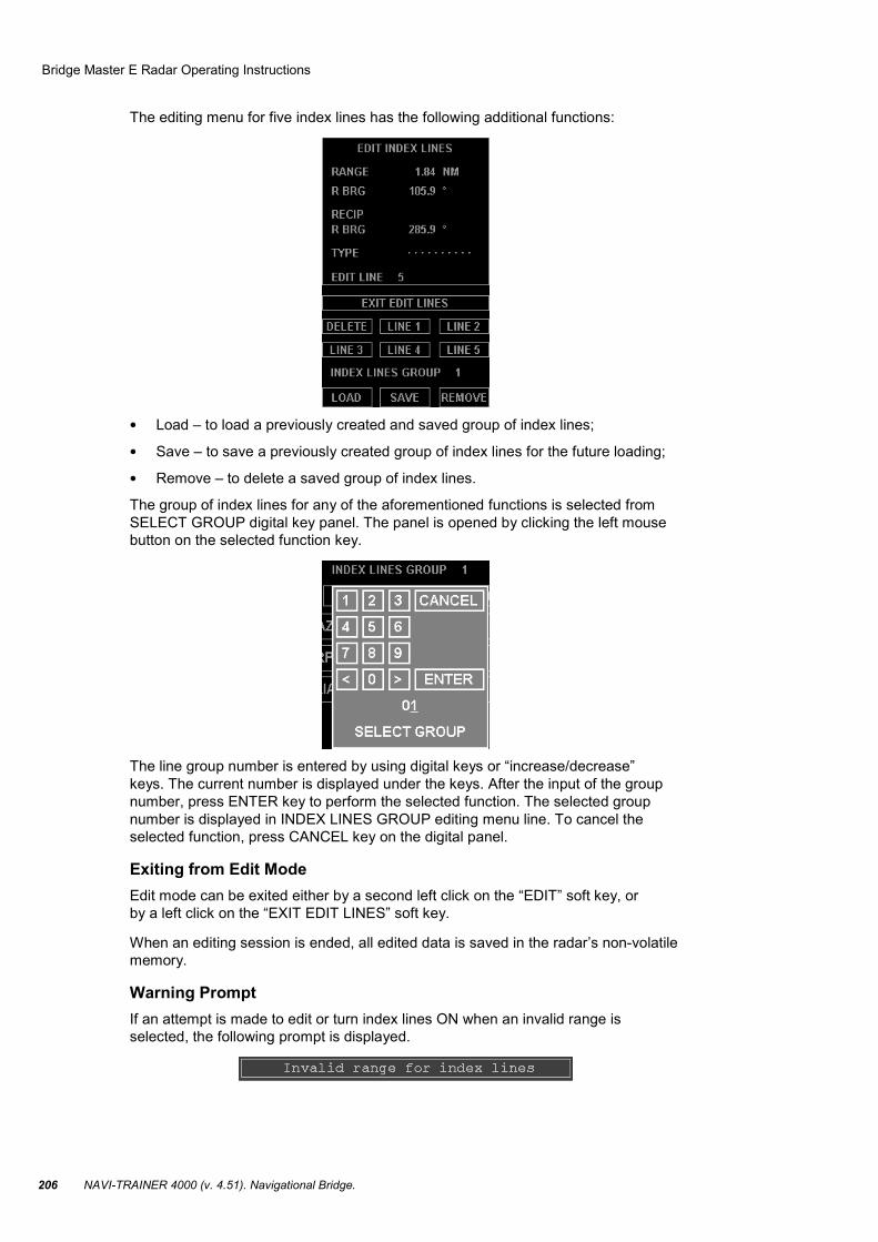
The editing menu for five index lines has the following additional functions:
• Load – to load a previously created and saved group of index lines;
• Save – to save a previously created group of index lines for the future loading;
• Remove – to delete a saved group of index lines.
The group of index lines for any of the aforementioned functions is selected from SELECT GROUP digital key panel. The panel is opened by clicking the left mouse button on the selected function key.
The line group number is entered by using digital keys or “increase/decrease” keys. The current number is displayed under the keys. After the input of the group number, press ENTER key to perform the selected function. The selected group number is displayed in INDEX LINES GROUP editing menu line. To cancel the selected function, press CANCEL key on the digital panel.
Exiting from Edit Mode Edit mode can be exited either by a second left click on the “EDIT” soft key, or by a left click on the “EXIT EDIT LINES” soft key.
When an editing session is ended, all edited data is saved in the radar’s non-volatile memory.
Warning Prompt If an attempt is made to edit or turn index lines ON when an invalid range is selected, the following prompt is displayed.

Bridge Master E Radar Operating Instructions
Chapter 5. Transas Radar/Arpa Imitators. 207
System Menu Introduction Then programmable “SYSTEM” key opens the system menu wherefrom Bridge Master E radar can be turned off, and another radar selection menu exited to (see the beginning of section Transas Radar////ARPA Imitators).
Access to the System Menu 1. Position the screen cursor on the programmable “SYSTEM” key.
2. Click the left mouse button to call the system menu.
In the current version, the system menu contains a single EXIT function. This function closes Bridge Master E radar screen and returns you to the selection menu of another radar available in the simulator.
To exit from the system menu without turning the radar off, click the left mouse button on EXIT SYSTEM line.
Tools

Bridge Master E Radar Operating Instructions
NAVI-TRAINER 4000 (v. 4.51). Navigational Bridge. 208
Introduction The “TOOLS” soft key provides access to a number of on-screen tools which allow the user to:
• Display a half or full circle “Rotating Cursor”;
• “Mark” up to 20 points of interest on screen.
Accessing the TOOLS A left click will reveal the TOOLS menu and an “EXIT TOOLS” soft key.
Note: A left click on the “EXIT TOOLS” soft key will close the menu.
Rotating Cursor A HALF circle, or FULL circle, rotating cursor can be displayed to provide a means of parallel indexing. The rotating cursor consists of a single white line diameter plus a number of equally spaced lines, which are perpendicular to the single line. The spacing of the perpendicular lines corresponds to the range ring spacing on all ranges. The rotating cursor is always centered on own ship.
The displayed cursor can be rotated by dragging (left click, hold and drag) the end points of the lines which pass through the video circle centre. The end points are marked with semi-circle.
To Turn the Rotating Cursor ON or OFF 1. Within the menu, position the screen cursor over the DISPLAY line under the
ROTATING CURSOR heading.
2. Left click to toggle the cursor ON or OFF.
Bridge Master E Radar Operating Instructions
Chapter 5. Transas Radar/Arpa Imitators. 209
To Select HALF or FULL Circle Cursor 1. Within the menu, position the screen cursor over the TYPE line.
2. Left click to toggle the cursor to HALF or FULL.
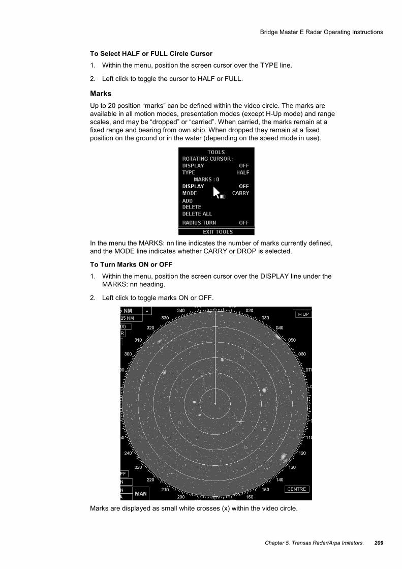
Marks Up to 20 position “marks” can be defined within the video circle. The marks are available in all motion modes, presentation modes (except H-Up mode) and range scales, and may be “dropped” or “carried”. When carried, the marks remain at a fixed range and bearing from own ship. When dropped they remain at a fixed position on the ground or in the water (depending on the speed mode in use).
In the menu the MARKS: nn line indicates the number of marks currently defined, and the MODE line indicates whether CARRY or DROP is selected.
To Turn Marks ON or OFF 1. Within the menu, position the screen cursor over the DISPLAY line under the
MARKS: nn heading.
2. Left click to toggle marks ON or OFF.
Marks are displayed as small white crosses (x) within the video circle.
Bridge Master E Radar Operating Instructions
NAVI-TRAINER 4000 (v. 4.51). Navigational Bridge. 210
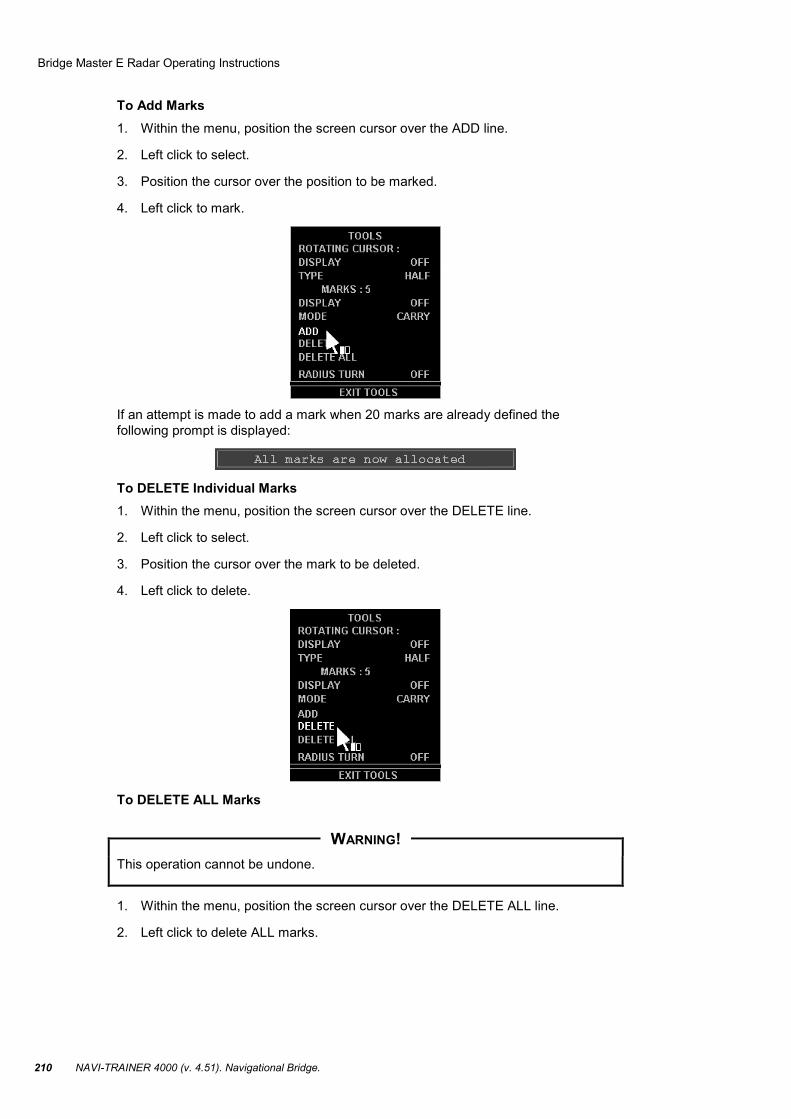
To Add Marks 1. Within the menu, position the screen cursor over the ADD line.
2. Left click to select.
3. Position the cursor over the position to be marked.
4. Left click to mark.
If an attempt is made to add a mark when 20 marks are already defined the following prompt is displayed:
To DELETE Individual Marks 1. Within the menu, position the screen cursor over the DELETE line.
2. Left click to select.
3. Position the cursor over the mark to be deleted.
4. Left click to delete.
To DELETE ALL Marks
This operation cannot be undone.
1. Within the menu, position the screen cursor over the DELETE ALL line.
2. Left click to delete ALL marks.
WARNING!
Bridge Master E Radar Operating Instructions
Chapter 5. Transas Radar/Arpa Imitators. 211
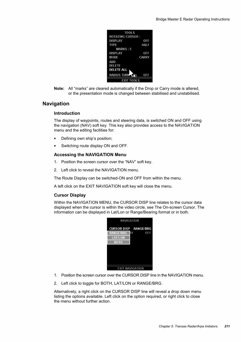
Note: All “marks” are cleared automatically if the Drop or Carry mode is altered, or the presentation mode is changed between stabilised and unstabilised.
Navigation Introduction The display of waypoints, routes and steering data, is switched ON and OFF using the navigation (NAV) soft key. This key also provides access to the NAVIGATION menu and the editing facilities for:
• Defining own ship’s position;
• Switching route display ON and OFF.
Accessing the NAVIGATION Menu 1. Position the screen cursor over the “NAV” soft key.
2. Left click to reveal the NAVIGATION menu.
The Route Display can be switched-ON and OFF from within the menu.
A left click on the EXIT NAVIGATION soft key will close the menu.
Cursor Display Within the NAVIGATION MENU, the CURSOR DISP line relates to the cursor data displayed when the cursor is within the video circle, see The On-screen Cursor. The information can be displayed in Lat/Lon or Range/Bearing format or in both.
1. Position the screen cursor over the CURSOR DISP line in the NAVIGATION menu.
2. Left click to toggle for BOTH, LAT/LON or RANGE/BRG.
Alternatively, a right click on the CURSOR DISP line will reveal a drop down menu listing the options available. Left click on the option required, or right click to close the menu without further action.

Bridge Master E Radar Operating Instructions
NAVI-TRAINER 4000 (v. 4.51). Navigational Bridge. 212
Turning the Route Display ON and OFF 1. Position the screen cursor over the ROUTE DISPLAY line in the NAVIGATION
menu.
2. Left click to toggle the route display ON or OFF.
Note: If H-Up mode is selected when route display is ON, the route display is inhibited until a stabilised mode is selected.
Warning Prompts If an attempt is made to turn the route display ON when the system is unstabilised, outside of the allowed range scale or outside allowed latitudes, an appropriate prompt is displayed.
Alarms Introduction Alarms are displayed at the right side of the video circle in the Alarms display box which is present in both Standby and Transmit modes.
A list of Alarms, together with a brief description and suggested remedial actions for each alarm, is given at the end of the chapter.
Types of Alarm There are three types of alarm:
1. Those which will clear automatically when the condition that caused the alarm is no longer present. For example, Bow Crossing CPA/TCPA and Position alarms.
2. Those which will clear as soon as they are acknowledged even if the condition that caused the alarm is still present. For example, AZ Entry alarms.
3. Those which will clear ONLY when the alarm has been acknowledged AND the condition that caused the alarm is no longer present. For example, Compass and Position alarms.
Alarm Display The Alarm display box provides an indication of the current alarm state and a means of acknowledging alarms, should any occur. There are three alarm states:
1. No Alarms.
2. Unacknowledged Alarms.
3. Acknowledged Alarms.

Bridge Master E Radar Operating Instructions
Chapter 5. Transas Radar/Arpa Imitators. 213
No Alarms If there are no alarms the caption NO ALARMS is displayed in GREEN.
Unacknowledged Alarms When an alarm condition is detected, that alarm flashes in RED in the Alarm display box. If more than one alarm condition exists, the alarm with the highest priority is displayed. The alarm remains displayed until it is either acknowledged, automatically cleared, or is replaced with an alarm of higher priority.
To Acknowledge an Alarm 1. Position the screen cursor over the Alarm display box.
2. Left click to acknowledge.
If there is more than one alarm, the acknowledged alarm is replaced by the next HIGHEST priority unacknowledged alarm.
3. Repeat the process until all alarms have been acknowledged. When there are no further unacknowledged alarms, the caption ALARMS is displayed in RED and is steady (i.e. is not flashing).
Acknowledged Alarms If there are acknowledged alarms but NO unacknowledged (new) alarms the caption ALARMS is displayed in RED and is steady.
Alarm Facilities A right click on the Alarm display box reveals a drop down list of up to six acknowledged alarms, arranged in order of priority and a drop down alarm menu.
Note: When required, user a right click to exit and remove the list.
The menu offers independent option:
BUZZER – when this is switched-ON, a beep is sounded for each new alarm.
The Alarm BUZZER To turn the alarm BUZZER ON or OFF:
1. Within the drop down menu, position the screen cursor over the BUZZER line.
2. Left click to toggle the buzzer ON or OFF.
3. Right click to close the menu.
List of Alarms The alarms, which are raised by the system, and appear in the ALARM box at the right hand side of the display, are given in alphabetical order in the table below. If more than one alarm exists, the alarm with the highest priority (the most important) is displayed.
Alarm Message Brief Description/Remedial Actions
BOW CROSS Bow Cross limit reached. Check limit – left click BC line in TOTE COMPASS Compass Alarm. Check wiring and SYSTEM menu – TEST DATA CPA/TCPA Limit reached. Check limits – left click on CPA or TCPA line in TOTE GZ ALARM EPA only. Target detected in guard zone LOG ERROR NO pulses or NO serial input. Check TYPE selected and wiring LOST REF ECHO REF target lost. Select new target or different speed source
LOST TARGET Tracked target no longer being seen STBY/TX ERR Transceiver failed to transmit TRACKS FULL Tracking maximum number of targets – cancel some

Bridge Master E Radar Operating Instructions
NAVI-TRAINER 4000 (v. 4.51). Navigational Bridge. 214
Search and Rescue (SART) Detection
A SART will only respond to an X-Band (3 cm) radar. It will NOT be seen on an S-BAND (10 cm) radar.
WARNING!
Bridge Master E Radar Operating Instructions
Chapter 5. Transas Radar/Arpa Imitators. 215
Introduction A Search and Rescue Transponder (SART) may be triggered by any X-Band (3 cm) radar within a range of approximately 8 nm. Each radar pulse received causes it to transmit a response which is swept repetitively across the complete radar frequency band. When interrogated, it first sweeps rapidly (0.4 µsec) through the band before beginning a relatively slow sweep (7.5 µsec) through the band back to the starting frequency. This process is repeated for a total of twelve complete cycles. At some point in the sweep, the SART frequency will match that of the interrogating radar and be within the pass band of the radar receiver. If the SART is within range, the frequency match during each of the 12 slow sweeps will produce a response on the radar display, thus a line of 12 dots equally spaced by about 0.64 nm will be shown.
Radar Range Scale When looking for a SART, it is preferable to use either the 6 or 12 nm range scale, Range Scales and Range Rings.
SART Range Errors When responses from only 12 low frequency sweeps are visible (when the SART is at a range greater than about 1 nm), the position at which the first dot is displayed may be as much as 0.64 nm beyond the true position of the SART. When the range closes so that the fast sweep responses are seen also, the first of these dots will be no more than 150 metres beyond the true position.
Radar Bandwidth This is normally matched to the radar pulse length and is usually switched with the range scale and the associated pulse length. Narrow bandwidths of 3-5 MHZ are used with long pulses on long range scales and wide bandwidths of 10-25 MHZ with short pulses on short ranges.
A radar bandwidth of less than 5 MHZ will attenuate the SART signal slightly, so it is preferable to use a medium bandwidth to ensure optimum detection of the SART, Radar Transmission Pulse Length.
Radar Side Lobes As the SART is approached, side lobes from the radar antenna may show the SART responses as a series of arcs or concentric rings. These can be removed by the use of the anti-clutter sea control although it may be operationally useful to observe the side lobes as they may be easier to detect in clutter conditions and also they will confirm that the SART is near to own ship.
Detuning the Radar To increase the visibility of the SART in clutter conditions, the radar may be detuned to reduce the clutter without reducing the SART response. The Bridge Master E Radar is equipped with automatic/manual frequency control and can be detune manually, Transceiver Tuning. Care should be taken in operating the radar in the detuned condition as other wanted navigational and anti-collision information may be removed. The tuning should be returned to normal operation as soon as possible.
Video Gain For maximum range SART detection the normal gain setting for long range detection should be used, i.e. with a light background noise speckle visible, Video Processing Controls.

Bridge Master E Radar Operating Instructions
NAVI-TRAINER 4000 (v. 4.51). Navigational Bridge. 216
Anti-clutter Sea Control For optimum range SART detection this control should be set to the minimum. Care should be exercised as wanted targets in sea clutter may be obscured. Note also that in clutter conditions the first few dots of the SART response may not be detectable, irrespective of the setting of the anti-clutter sea control. In this case, the position of the SART may be estimated by measuring 9.5 nm from the further dot back towards own ship.
The BridgeMaster E Radar has automatic/manual anti-clutter sea control facilities, Video Processing Controls. Because of the way in which the automatic sea control functions, the operator is advised to use manual control initially until the SART has been detected. The effect of the auto sea control on the SART response can then be compared with manual control.
Anti-clutter Rain Control This should be used normally (i.e. to break up areas of rain) when trying to detect a SART response which, being a series of dots, is not affected by the action of the anti-clutter rain circuitry. Note that Racon responses, which are often in the form of a long flash, will be affected by the use of this control.
The BridgeMaster E Radar has automatic/manual anti-clutter rain control facilities, Video Processing Controls. Because of the way in which the automatic control functions, the operator is advised to use manual control initially until the SART has been detected. The effect of the auto rain control on the SART response can then be compared with manual control.