Embed Size (px)
Citation preview

motrona GmbH, Zeppelinstraße 16, DE - 78244 Gottmadingen, Tel. +49 (0) 7731 9332-0, Fax +49 (0) 7731 9332-30, [email protected], www.motrona.com
Operating Manual
CT150 Precision Controller for Rotating Cutters, Rotary Punchers and Printing Screens
Product features:
Stand-alone unit for full closed loop control of the cutter drive
Fully synchronous motion while cut or print is in progress
Variable cutting length or printing pitch by S-shape speed profile of the roll
Excellent accuracy and dynamics by only 150 µs of response time
Index and print mark control included
Easy setup and commissioning by Windows operator software
Parallel and serial and optional CANopen interface for auxiliary PLC and PC control
Includes batch counters, line speed control and more facilities
18 to 30 VDC power supply

Ct150_14d_oi_e.doc / Dez-15 Page 2 / 55
Version: Description:
CT15013B/TJ/Oct. 03/S.23/24/38 control & status word, encoder inputs, maximum frequency
CT15014/TJ/Dec. 04/S.23 cutting length error readable
CT15014B_e/Bo/Jul-08 modulations into the motrona format
CT15014C_e/pp/Nov-11 chapter 20: replaced double by 8 times line speed
Ct150_14d_oi/Dez-11/ag Legal Notices added. New design & chapter for “Safety Instructions“.
“Technical specifications” actualized. Smaller corrections/modulations
Legal notices:
All contents included in this manual are protected by the terms of use and copyrights of motrona GmbH. Any
reproduction, modification, usage or publication in other electronic and printed media as well as in the internet
requires prior written authorization by motrona GmbH.
Ct150_14d_oi_e.doc / Dez-15 Page 3 / 55
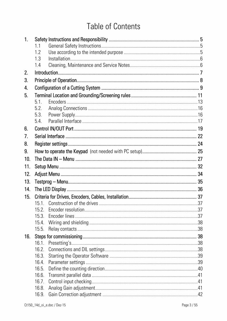
Table of Contents
1. Safety Instructions and Responsibility ......................................................................... 5
1.1 General Safety Instructions ................................................................................... 5
1.2 Use according to the intended purpose ................................................................ 5
1.3 Installation ............................................................................................................. 6
1.4 Cleaning, Maintenance and Service Notes ........................................................... 6
2. Introduction .................................................................................................................. 7
3. Principle of Operation................................................................................................... 8
4. Configuration of a Cutting System ............................................................................... 9
5. Terminal Location and Grounding/Screening rules ..................................................... 11
5.1. Encoders .............................................................................................................. 13
5.2. Analog Connections ............................................................................................ 16
5.3. Power Supply ....................................................................................................... 16
5.4. Parallel Interface ................................................................................................. 17
6. Control IN/OUT Port ................................................................................................... 19
7. Serial Interface .......................................................................................................... 22
8. Register settings ........................................................................................................ 24
9. How to operate the Keypad (not needed with PC setup) ............................................ 25
10. The Data IN – Menu .................................................................................................. 27
11. Setup Menu ............................................................................................................... 32
12. Adjust Menu .............................................................................................................. 34
13. Testprog – Menu........................................................................................................ 35
14. The LED Display ......................................................................................................... 36
15. Criteria for Drives, Encoders, Cables, Installation ....................................................... 37
15.1. Construction of the drives ................................................................................... 37
15.2. Encoder resolution ............................................................................................... 37
15.3. Encoder lines ....................................................................................................... 37
15.4. Wiring and shielding ........................................................................................... 38
15.5. Relay contacts ..................................................................................................... 38
16. Steps for commissioning ............................................................................................ 38
16.1. Presetting’s .......................................................................................................... 38
16.2. Connections and DIL settings .............................................................................. 38
16.3. Starting the Operator Software .......................................................................... 39
16.4. Parameter settings .............................................................................................. 39
16.5. Define the counting direction .............................................................................. 40
16.6. Transmit parallel data ......................................................................................... 41
16.7. Control input checking ......................................................................................... 41
16.8. Analog Gain adjustment ...................................................................................... 41
16.9. Gain Correction adjustment ................................................................................ 42

Ct150_14d_oi_e.doc / Dez-15 Page 4 / 55
16.10. Cutting cycle simulation ...................................................................................... 42
16.11. Visualize a cutting cycle by the OS3.2 ................................................................ 43
17. Hints to improve performance .................................................................................... 44
18. Auxiliary Register and Command Codes ..................................................................... 45
19. General Master Reset and Erase of EEProm ............................................................... 47
20. Physical Range of Cutting Lengths ............................................................................. 47
20.1. The shortest length possible ............................................................................... 48
20.2. The longest length possible ................................................................................ 48
20.3. Dynamic requirements for the roll drive .............................................................. 49
21. The BY 106-X Remote Thumbwheel Switch ............................................................... 50
22. Technical Specifications ............................................................................................ 51
23. Dimensions ................................................................................................................ 52
24. Serial code list ........................................................................................................... 53
24.1. Parameters .......................................................................................................... 53
24.2. Inputs ................................................................................................................... 54
24.3. Variables .............................................................................................................. 55

Ct150_14d_oi_e.doc / Dez-15 Page 5 / 55
1. Safety Instructions and Responsibility
1.1 General Safety Instructions This operation manual is a significant component of the unit and includes important rules and
hints about the installation, function and usage. Non-observance can result in damage and/or
impairment of the functions to the unit or the machine or even in injury to persons using the
equipment!
Please read the following instructions carefully before operating the device and observe all
safety and warning instructions! Keep the manual for later use.
A pertinent qualification of the respective staff is a fundamental requirement in order to use
these manual. The unit must be installed, connected and put into operation by a qualified
electrician.
Liability exclusion: The manufacturer is not liable for personal injury and/or damage to property
and for consequential damage, due to incorrect handling, installation and operation. Further
claims, due to errors in the operation manual as well as misinterpretations are excluded from
liability.
In addition the manufacturer reserve the right to modify the hardware, software or operation
manual at any time and without prior notice. Therefore, there might be minor differences
between the unit and the descriptions in operation manual.
The raiser respectively positioner is exclusively responsible for the safety of the system and
equipment where the unit will be integrated.
During installation or maintenance all general and also all country- and application-specific
safety rules and standards must be observed.
If the device is used in processes, where a failure or faulty operation could damage the system
or injure persons, appropriate precautions to avoid such consequences must be taken.
1.2 Use according to the intended purpose The unit is intended exclusively for use in industrial machines, constructions and systems. Non-
conforming usage does not correspond to the provisions and lies within the sole responsibility
of the user. The manufacturer is not liable for damages which has arisen through unsuitable
and improper use.
Please note that device may only be installed in proper form and used in a technically perfect
condition - in accordance to the Technical Specifications (see chapter 22). The device is not
suitable for operation in explosion-proof areas or areas which are excluded by the EN 61010-1
standard.
Ct150_14d_oi_e.doc / Dez-15 Page 6 / 55
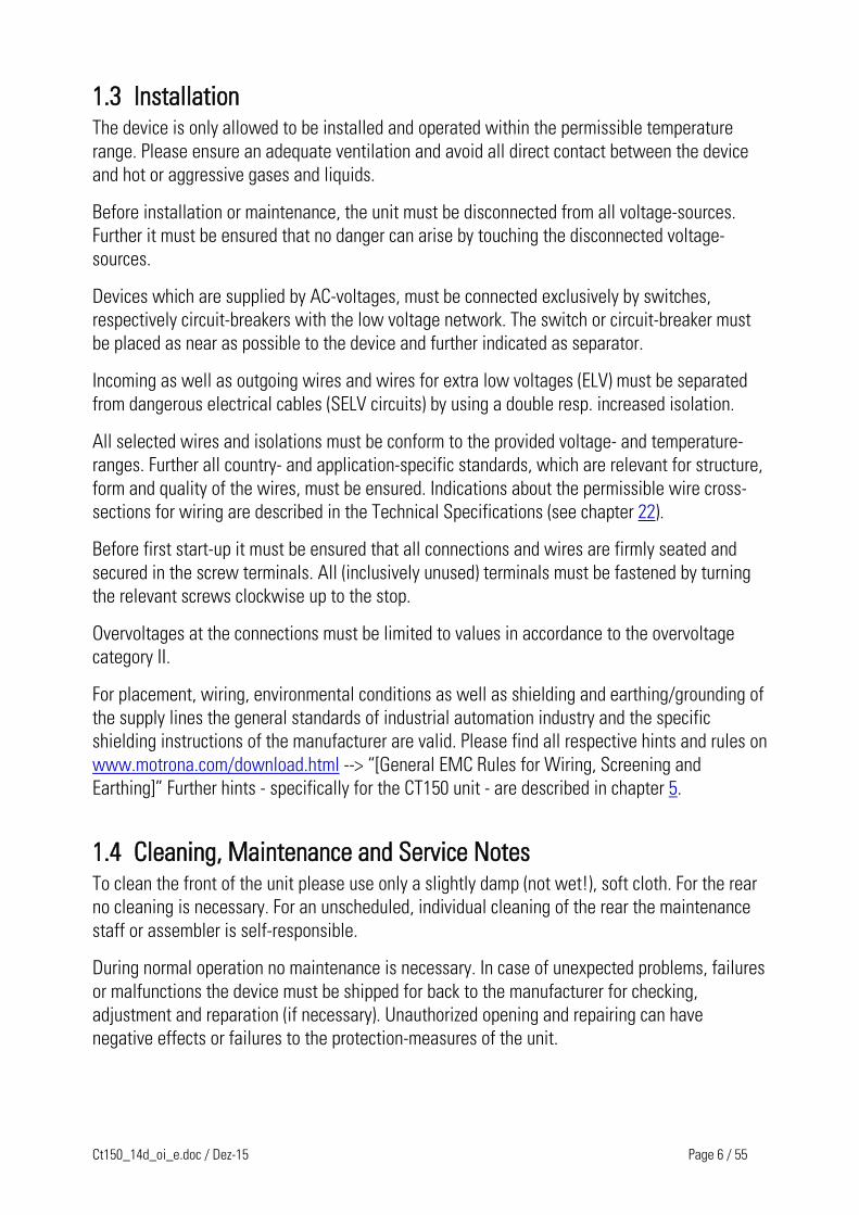
1.3 Installation The device is only allowed to be installed and operated within the permissible temperature
range. Please ensure an adequate ventilation and avoid all direct contact between the device
and hot or aggressive gases and liquids.
Before installation or maintenance, the unit must be disconnected from all voltage-sources.
Further it must be ensured that no danger can arise by touching the disconnected voltage-
sources.
Devices which are supplied by AC-voltages, must be connected exclusively by switches,
respectively circuit-breakers with the low voltage network. The switch or circuit-breaker must
be placed as near as possible to the device and further indicated as separator.
Incoming as well as outgoing wires and wires for extra low voltages (ELV) must be separated
from dangerous electrical cables (SELV circuits) by using a double resp. increased isolation.
All selected wires and isolations must be conform to the provided voltage- and temperature-
ranges. Further all country- and application-specific standards, which are relevant for structure,
form and quality of the wires, must be ensured. Indications about the permissible wire cross-
sections for wiring are described in the Technical Specifications (see chapter 22).
Before first start-up it must be ensured that all connections and wires are firmly seated and
secured in the screw terminals. All (inclusively unused) terminals must be fastened by turning
the relevant screws clockwise up to the stop.
Overvoltages at the connections must be limited to values in accordance to the overvoltage
category II.
For placement, wiring, environmental conditions as well as shielding and earthing/grounding of
the supply lines the general standards of industrial automation industry and the specific
shielding instructions of the manufacturer are valid. Please find all respective hints and rules on
www.motrona.com/download.html --> “[General EMC Rules for Wiring, Screening and
Earthing]” Further hints - specifically for the CT150 unit - are described in chapter 5.
1.4 Cleaning, Maintenance and Service Notes To clean the front of the unit please use only a slightly damp (not wet!), soft cloth. For the rear
no cleaning is necessary. For an unscheduled, individual cleaning of the rear the maintenance
staff or assembler is self-responsible.
During normal operation no maintenance is necessary. In case of unexpected problems, failures
or malfunctions the device must be shipped for back to the manufacturer for checking,
adjustment and reparation (if necessary). Unauthorized opening and repairing can have
negative effects or failures to the protection-measures of the unit.

Ct150_14d_oi_e.doc / Dez-15 Page 7 / 55
2. Introduction The CT150 cutting controller is
technically based on the BY150 high
performance synchro controls. The
software however has been especially
designed for rotating cutter systems and
printing applications, with consideration
of maximum cutting efficiency and
accuracy at most careful treatment of all
mechanical parts.
All parameters are set fully digital and no
potentiometers must be adjusted. The
unit provides a small keypad with LCD
display for register settings. Also a
windows operator software is included
on disc, featuring easy setup by a PC /
Laptop / Notebook computer.
Some of the most important registers are accessible via parallel interface, allowing to preset
cutting length and other variables by a simple BCD thumbwheel switch or a PLC parallel output.
All internal registers are accessible by serial RS232 or 485 or CANopen communication.
The mechanical construction provides a fully closed 19“ steel cassette with all connections on
the front, guaranteeing excellent attributes with EMC immunity and emission. The cassette can
be mounted into any standard rack. With use of option SM 150, also easy mounting on DIN
rails is possible.
In some sections, this description uses expressions like „C02“, „C03“ which represent the serial
access code to the corresponding registers.
The unit is suitable for control of cutting applications as well as for partial printing screens.
This manual always says “cutting“ or “cut“ and the reader may replace this by “printing“ when
applicable.
BCD-thumbwheelswicht or PLC
20CT150
PIRS485
or CAN
TX720Operator terminal
1 2 3 4 5CT150 RS232CT150
PC
Exampels how to operate the CT150 controller
Fig. 1

Ct150_14d_oi_e.doc / Dez-15 Page 8 / 55
3. Principle of Operation When a cutting process needs synchronous circumferential speed of the cutting tool with the
line, the only length that can be cut is the one corresponding to the circumference of the roll
(at constant rotational speed). Change of the cutting length needs exchange of the roll against
another one with appropriate diameter.
The CT150 controller uses a two- speed principle featuring full synchronism while the cut is in
progress, but taking a different roll speed when the tool is outside the cutting zone (where
synchronism is not necessary). So, in terms of one revolution of the roll, we are talking about
two speed zones: The synchronous cutting zone (which is register settable) and the
asynchronous zone where the roll follows a speed profile calculated by the processor in order
to get the desired cutting length. The CT150 calculates the speed profile of the „asynchronous
zone“ in a way that the physically possible minimum of acceleration and deceleration torque is
applied to the drive with respect to actual line speed and preset cutting length.
With length settings smaller than the roll circumference, the „asynchronous zone“ will take
higher speeds than the „synchronous zone“. With length settings longer than the
circumference, the asynchronous speed will be lower and the drive can even go to a temporary
standstill if necessary. Fig 1 shows two typical speed profiles.
CutV
Line
Sync Zone
Length > Circumferencet
CutV
LineSync Zone
Length < Circumferencet
Fig. 2
Continuous closed loop control of the relative roll position with respect to the length progress
of the line, combined with an update time as short as 150 µsec, provide best cutting accuracy
and exceptional smooth motion of the cutting roll at any time.
It is a must to use a 4 quadrant drive or a servo drive for the cutting roll, because the CT150
must be able to accelerate and decelerate the roll under real closed loop conditions. However,
no special requirements are necessary for the line drive, and also a simple measuring wheel on
the material line is good for full performance.

Ct150_14d_oi_e.doc / Dez-15 Page 9 / 55
4. Configuration of a Cutting System In general, the Master drive will be the drive of a feed roll. With many applications, and with
special regard to possible slip, a measuring wheel with encoder can be better.
CT150 version 10A or higher can operate with or without analog feed forward signal. In
general, for new applications, fully digital operation will be chosen (line speed taken from the
master encoder only). But in order to be fully compatible to all former versions, the unit can also
operate with an analog input proportional to the line speed. Analog feed forward signal must
be used, when for reasons of poor master encoder resolution the master frequency does not
reach at least 1 kHz with maximum line speed.
The CT150 controller uses encoders with RS422- TTL line driver outputs (5 V, A, /A, B, /B).
Where you must apply HTL encoders (10 … 30 V, A and B output), it is necessary to use our
level converter PU210 which converts your HTL signals to the proper RS422 standard
Both, line encoder and roll encoder, should have at least 5 times the resolution of the maximum
cutting error you can accept. Please note you can set the unit to multiple- edge- counting
(Section 5.1) which can reduce the real number of ppr correspondingly. At any time you must be
aware that the CT150 controller accepts cutting errors of + / - 5 encoder increments or edge
counts, whatever this may be in terms of length tolerance. Please observe the maximum
encoder frequency which is 300 kHz.
The unit must receive a „cutting pulse“ with each revolution of the cutting roll. The rising edge
of this cutting pulse must be physically located somewhere in the synchronous zone
(i.e. around the position where the tool performs the cut). With respect to this rising edge, the
user can set a „prior to cut“ and an „after cut“ zone where the tool must be synchronous to the
line.
If applicable, a print mark sensor can be connected for fully automatic adjust of the cut with
respect to a print mark. Two Trim inputs provide manual displacement of the cutting point on
the material and also allow to jog the roll with the line in standstill. Fig. 2 shows the general
block diagram of the CT150 controller.

Ct150_14d_oi_e.doc / Dez-15 Page 10 / 55
Cutter driveRollEncoder
+/-10V(or +10V)
AnalogueOutput
SlaveInput
MasterInputA, /A, B, /B A, /A, B, /B
Power24VDC
RS232 ReadyReserve
Line outMarkwindow openAlert -
Cut too shortCut too longAlert +
Parallel-Data Input
ResetTrimm +Trimm -Read PIActivateProg 1/2Store EEPromStart/StopReserveReset MarkCutting pulsePrint mark
RS485
CAN
CT150
ControlInputs
Interface
Outputs
Measuring wheel
LineEncoder
PLC orBCD switch
Bold printed connections are “must”Ohter connections are “can”
Fig. 3
Fig. 3

Ct150_14d_oi_e.doc / Dez-15 Page 11 / 55
5. Terminal Location and Grounding/Screening rules
m o rona
Fig. 4
For reasons of proper screening, it is a must to follow the subsequent instructions.
Where you don’t exactly observe these grounding and screening rules, it
is almost for sure that you will have problems later!
a. The minus wire of the power supply must be connected to the grounding screw on the front
plate of the CT150 controller with a short wire of at least 0.75 mm². On site of the power
supply, the minus output must be earthed.
Where the wires between power unit and CT150 controller are longer than e.g. 1 meter, it
is advisable to ground the front plate of the controller again by a separate wire, on the
shortest way possible.
+24V
CT150
Supplement short earthing when power cable is long
Power Supply PE
Fig. 5

Ct150_14d_oi_e.doc / Dez-15 Page 12 / 55
b. All screens on the controller side must be connected to the housing of the corresponding
SUB-D-connector. This is valid for encoder cables, analog output and PI or PO lines. Where
you use SUB-D-connectors with a plastic housing, you must solder the screen to the
metallic frame of the connector.
At any time you must be sure the screen gets a proper contact to the front fascia of the unit
when connected to the controller.
Screen
Fig. 6
c. When encoder cables are interrupted by terminal boxes or intermediate connectors on their
way from the controller to the encoder, you must connect the screen to the Minus wire of
the encoder supply there, but never to earth potential again!
to encoderEncoder cable
to CT150
Minus of encoder supply
Screen
Tie Minus of encoder supply and screen together whereever you interruptthe encoder cable by terminal or connectors. Make sure the screen can never get any earth potential here!
Fig. 7
d. When the cable arrives at the encoder site, the screen must again be connected to the
Minus wire of the encoder supply, but not at all grounded to earth. In general, there are two
types of encoder connections:
Make sure the screen of the cable is connected to the Minus supply of the encoder, but does not touch the metallic housing of the connector.
Shaft
Encoder
Encoder with plug connector
Fig. 8
Leave this screen fully unconnectedhere to avoid illegal double earthing!(Screen is internally earthed to the encoder housing).
from CT150
Shaft
Encoder
Encoder with cable end
Connect screen to the Minus wire of the encoder supply here. Avoid any earth connection via contact to housings ect.
Fig.9
Ct150_14d_oi_e.doc / Dez-15 Page 13 / 55
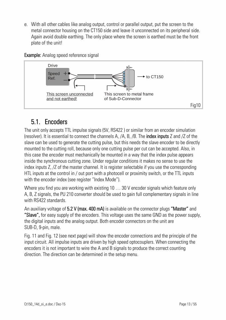
e. With all other cables like analog output, control or parallel output, put the screen to the
metal connector housing on the CT150 side and leave it unconnected on its peripheral side.
Again avoid double earthing. The only place where the screen is earthed must be the front
plate of the unit!
Example: Analog speed reference signal
This screen to metal frameof Sub-D-Connector
to CT150SpeedRef.
Drive
This screen unconnectedand not earthed!
Fig10
5.1. Encoders The unit only accepts TTL impulse signals (5V, RS422 ) or similar from an encoder simulation
(resolver). It is essential to connect the channels A, /A, B, /B. The index inputs Z and /Z of the
slave can be used to generate the cutting pulse, but this needs the slave encoder to be directly
mounted to the cutting roll, because only one cutting pulse per cut can be accepted. Also, in
this case the encoder must mechanically be mounted in a way that the index pulse appears
inside the synchronous cutting zone. Under regular conditions it makes no sense to use the
index inputs Z, /Z of the master channel. It is register selectable if you use the corresponding
HTL inputs at the control in / out port with a photocell or proximity switch, or the TTL inputs
with the encoder index (see register “Index Mode”).
Where you find you are working with existing 10 … 30 V encoder signals which feature only
A, B, Z signals, the PU 210 converter should be used to gain full complementary signals in line
with RS422 standards.
An auxiliary voltage of 5.2 V (max. 400 mA) is available on the connector plugs “Master“ and
“Slave“, for easy supply of the encoders. This voltage uses the same GND as the power supply,
the digital inputs and the analog output. Both encoder connectors on the unit are
SUB-D, 9-pin, male.
Fig. 11 and Fig. 12 (see next page) will show the encoder connections and the principle of the
input circuit. All impulse inputs are driven by high speed optocouplers. When connecting the
encoders it is not important to wire the A and B signals to produce the correct counting
direction. The direction can be determined in the setup menu.

Ct150_14d_oi_e.doc / Dez-15 Page 14 / 55
/Z Z /B
1 2 3 4 5986 7
B /A A
/Z Z /B
1 2 3 4 5986 7
B /A A
GND
VCC int.
DC
DC GND int.GND int.
DIL-Switches 1-4 have no function. (different from previous hardware versions)
0V
+5.2V
Fig. 11
GND
VCC int.
DC
DC GND int.GND int.
+5.2V
0V
4
A220
Opto
/A220
Opto
5Input current approx. 15mA per channel
Input circuit (principle)
Fig. 12
Important:
With encoders, supplied by the CT150:
Connector pins 4 and 5 provide an encoder supply output of 5.2 V.
With encoders, supplied by an external source, or when an encoder simulation from the
drive is used (Common GND operation): Use connector pin 5 as common 0 V potential.
For fully potential-free operation:
Connect only A, /A and B, /B and leave terminal 5 (Common) unconnected.
For reason of best noise immunity, we recommend to use potential free operation
wherever you have line driver signals with remote supply.
Warnings: Pin 4 of the Master and Slave encoder connectors is a supply output
and you must never apply external voltage to this pin. Serious damage of the
controller would be the result!
Where you use one common encoder for feedback of the drive and feedback for the CT150 at
the same time, there may come up interference problems. You can use a motrona GV150
impulse splitter to eliminate any kind of problems. In most applications, the common encoder
would also work fine when it is supplied by the drive and the CT150 operates in fully
differential mode like shown.

Ct150_14d_oi_e.doc / Dez-15 Page 15 / 55
Encoder/A
A
B
/B
Schirm
4 (NC)4 (NC)
9
1
2
3
5 (NC)
Do not connect pin 4 or 5for fully differential operation!
Drive
CT150
Fig. 13
DIL switches S1 / 5 - 8 provide the selection of the encoder edge counting. It is possible with
complementary signals to count with times 1, 2, or 4 without any fear of miscounting. The
selection always applies separately to the master and the slave input signals.
Master:
Fig. 14
DIL-Pos. 5 DIL-Pos. 6 Edge count
ON ON X1
OFF ON X2
ON OFF X4
OFF OFF Counter disabled
Slave:
DIL-Pos. 7 DIL-Pos. 8 Edge count
ON ON X1
OFF ON X2
ON OFF X4
OFF OFF Counter disabled
Please note, that
The maximum frequency of the CT150 refers to the total number of edges
counted, i.e. 300 kHz (x1) or 150 kHz (x2) or 75 kHz (x4).
Impulse numbers, to be entered upon setup, also refer to the total number
of edges counted, i.e. the entry data must be doubled with (x2) etc.
When possible, you should set the switches in a way to produce approximately
similar impulse numbers on Master and Slave side to achieve best operation, i.e.
4096 impulses x 1 on the Master side and 1000 impulses x 4 on the Slave side.

Ct150_14d_oi_e.doc / Dez-15 Page 16 / 55
5.2. Analog Connections All the Analog input and output signals can be found on the 9-Pin SUB-D connector (female)
marked as "Analog" on the front plate. The analog common GND is internally connected to the
minus of the 24 VDC supply. All analog levels are in range +/- 10 Volts.
When you use the digital feed- forward mode, you must only connect pin 7 which is the analog
output for the cutter drive speed reference.
When you use the analog feed- forward mode, you must apply a 0 - 10 V analog signal
proportional to the line speed to pin 6.
Pin 4, 5, 8 and 9 are for special purpose and must normally remain unconnected.
Fig. 15
5.3. Power Supply The CT150 operates from an unstabilized 24 VDC supply (+/- 25%), however, the voltage
including ripple should not exceed the following limits (18 V...30 V). The supply of the CT150 is
both electrically and mechanically protected against wrong polarity misconnection by
protection diodes and a special plug.
Warning: At pin 1 of the "PI" connector and pin 1 of the "PI/PO" connector, a
+24 V output is available for easier wiring of input and output supplies. This
voltage is taken from behind of a current limiting resistor. Short circuiting
these outputs to GND can burn the resistor or internal printed lines.
GND
aux. out
470uF
+24VR
2 Ohm/1Watt
aux. out
Internal
Pin 1 des PI/PO- connector
Pin 1 des PI- connector
Fig. 16

Ct150_14d_oi_e.doc / Dez-15 Page 17 / 55
5.4. Parallel Interface The interface provides remote setting of operational and configuration registers. It receives
BCD or binary data (selectable) from a remote thumbwheel switch or PLC control. There are four
binary coded select lines which provide up to 16 addresses being accessible, via 20 data lines.
The register parameters are stored in the following manner:
a) Store the parallel data upon a Read pulse. The data is then latched into the internal
buffer, without affecting the control operation at this point.
b) Activate data upon an input pulse. All the data stored in the buffer is loaded and
executed. For information’s about transfer and activation please go to chapter 6.
It is easy to see how 16 external registers may be easily loaded into the CT150. The connection
of the parallel interface is a 25 pin SUB-D connector (male) which is marked as "PI" on the front
fascia.
All inputs are fully PLC compatible. All signals refer to GND and the minus potential of the supply.
Important Advice: Upon power up, the unit loads the full register set stored in its
EEProm. Data transmitted from the parallel and/or serial interface will overwrite
the operational RAM-data, but not the corresponding EEProm registers. As a
result, when powering up, any parallel or serial data will be replaced by EEProm
data, until it is overwritten again.
The RAM data however can be restored to the EEProm at any time by parallel or serial
command.
Parallel interface operations must keep the following timing conditions:
Data valid
T1 T2 T1 min. = 5 msec.T2 min. = 5 msec.
BCD DATA
Read impulse
Fig. 17

Ct150_14d_oi_e.doc / Dez-15 Page 18 / 55
Data latch occurs with the positive transition of the strobe pulse. Data lines must be in a valid
state at least 5 msec. prior to the strobe, and remain present for an additional 5 msec. while
the data is read. There is no upper limit for T1 and T2.
+24V 1S1 14S2 2S3 15S4 3BCD1 16BCD2 4
BCD4 17BCD85
186
197
208
219
2210
2311
2412
2513
BCD1 BCD2 BCD4 BCD8BCD1 BCD2 BCD4 BCD8BCD1 BCD2 BCD4 BCD8BCD1 BCD2 BCD4 BCD8
SelectLines
Low orderdigit
(LSD)
High orderdigit
(MSD)
MSD -3
MSD -2
MSD -1
S4 S3 S2 S1
0 0 0 0 Length (C 05)
0 0 0 1 Pho-Offs. (C 12)
0 0 1 0 Pho-Cut (C 11)
0 0 1 1 P1 (C 08)
0 1 0 0 Cut (C 07)
0 1 0 1 Circ 1 (C 00)
0 1 1 0 (C 02)
When using binary format pin 16 is the LBS and pin 13 is the MSB.
Cut
P2
Circ 2
0 1 1 1 (C 04)Trimm
1 0 0 0 (C 09)Cut/Rev
1 0 0 1 (C 10)Mark/Len
1 0 1 0 (C 40)Mode
1 0 1 1 (C 17)Ramptime
1 1 0 0 (C 46)Gain - Cor
1 1 0 1 (C 48)Gain - Tot
1 1 1 0 (C 01)ppr1
1 1 1 1 (C 03)ppr2
With signed parameters the most significant bit (pin 13) is used as sign bit (low=+).
Fig. 18
Important: When the power supply of the unit is switched off,
there must not be a voltage at the parallel interface.

Ct150_14d_oi_e.doc / Dez-15 Page 19 / 55
6. Control IN/OUT Port There are 12 control input lines and 8 control output lines available on the 25 Pin Sub -D -
Connector (female). This is marked on the fascia PI/PO. All the inputs are the same as the
parallel inputs. All the outputs are opto-isolated transistor outputs which are PLC compatible.
Fig. 19
Important: When the power supply of the unit is switched off,
there must not be a voltage at the parallel interface.
Inputs Description
Reset (13):
A High signal switches off the digital closed loop control and the unit only
operates in an analog open loop. When a Reset signal is applied with the
Start / Stop input in High state, the unit also executes a new initial software
startup cycle.
Trim + (25):
Trim - (12):
Shifts the cutting position forward or reverse, i. e. the unit temporarily cuts
longer or shorter pieces while one of the Trim inputs is High. With print mark
registration, the Trim inputs can be used to adjust the cutting position with
respect to the mark. Once it has been placed correctly, a „Store to EEprom“
command will store the cutting position and the unit will find the correct
position automatically again after power down. Trim inputs can also be used
to jog the roll while the line stands still.
Read PI data
(24)*:
Reads values of BCD or Binary code on parallel input. These values are stored
in 16 separate buffer memories, as selected. This data is not activated until
the following input is made.

Ct150_14d_oi_e.doc / Dez-15 Page 20 / 55
Inputs Description
Activate PI
data ( 11 )* :
A rising edge of this input transfers the data from the buffer memory to the
operating memory.
PROG.1 /
PROG.2 (23):
The unit can store two completely different sets of parameters and,
depending of the production, use either parameter set 1 (Pin 23 low) or
parameter set 2 (pin 23 high).
Signal changes on this input will only become active when
a) either power is switched off and on again
b) or the start/stop input goes high and the cutting roll comes to
standstill
Store RAM to
EEPRom (10) :
A rising edge at this input stores all actual operational data to the EEPRom
and the same data set will be loaded again after power down. It is
recommended to use this command only at standstill or low speed, because it
could affect the accuracy of the subsequent cut.
This function should only be performed at machine standstill, because
storage process could affect the cutting accuracy of the next cut.
Start / Stop
(22):
With Low state, the unit operates in a normal cutting cycle. When the input
goes High, the subsequent cut is still executed normally and then the cutting
roll decelerates to a closed loop stop position, following the ramp set to the
“Ramptime” register.
Reset mark
counter (21):
When using print mark operation, many times we find several marks on one
size of the sheet to be cut, and only one of these marks is valid for
registration. The unit can automatically blank out the other marks by defining
the active mark as follows: Set this input to high when the valid print mark is
close to the print mark sensor, but is not yet sensed. Move the line slowly
until the sensor detects the mark and switches from low to high (rising edge
required!). The Reset mark counter input must go back to low state before the
sensor generates the next rising edge from the following mark. This stores
the position of the valid print mark and the unit will not trigger to the other
marks between. See also register Mark/Window.
Cutting pulse
( 8 ) :
This input must receive one impulse per revolution of the cutting roll
(unless the TTL index pulse of the slave encoder is used) and the rising edge
of the impulse must be somewhere in the cutting zone, since it serves as
reference for definition of the synchronous phase. When you have several
tools on the roll (i. e. for several cuts per revolution), refer to register
„Cuts / rev“.
*) N.B It is permissible to activate both „Read“ and „Activate“ inputs at the same time.
Thus for instance, a common input can be used to enter a new cutting length.
Ct150_14d_oi_e.doc / Dez-15 Page 21 / 55
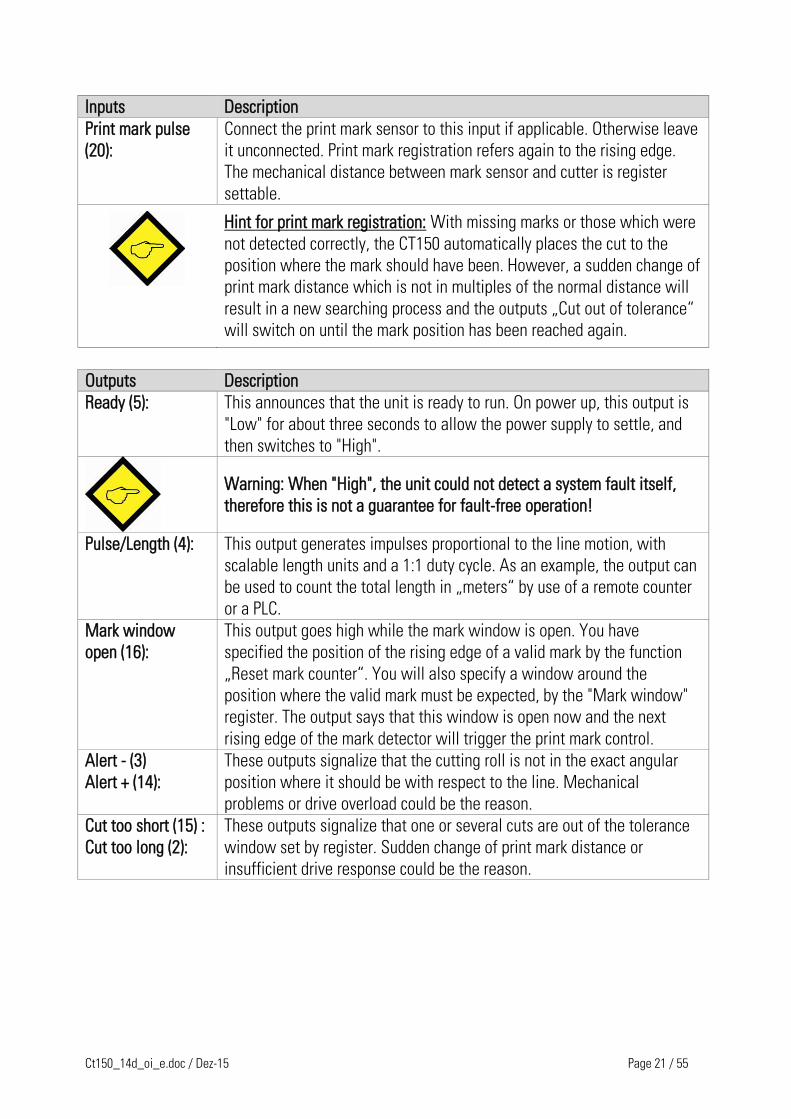
Inputs Description
Print mark pulse
(20):
Connect the print mark sensor to this input if applicable. Otherwise leave
it unconnected. Print mark registration refers again to the rising edge.
The mechanical distance between mark sensor and cutter is register
settable.
Hint for print mark registration: With missing marks or those which were
not detected correctly, the CT150 automatically places the cut to the
position where the mark should have been. However, a sudden change of
print mark distance which is not in multiples of the normal distance will
result in a new searching process and the outputs „Cut out of tolerance“
will switch on until the mark position has been reached again.
Outputs Description
Ready (5):
This announces that the unit is ready to run. On power up, this output is
"Low" for about three seconds to allow the power supply to settle, and
then switches to "High".
Warning: When "High", the unit could not detect a system fault itself,
therefore this is not a guarantee for fault-free operation!
Pulse/Length (4):
This output generates impulses proportional to the line motion, with
scalable length units and a 1:1 duty cycle. As an example, the output can
be used to count the total length in „meters“ by use of a remote counter
or a PLC.
Mark window
open (16):
This output goes high while the mark window is open. You have
specified the position of the rising edge of a valid mark by the function
„Reset mark counter“. You will also specify a window around the
position where the valid mark must be expected, by the "Mark window"
register. The output says that this window is open now and the next
rising edge of the mark detector will trigger the print mark control.
Alert - (3)
Alert + (14):
These outputs signalize that the cutting roll is not in the exact angular
position where it should be with respect to the line. Mechanical
problems or drive overload could be the reason.
Cut too short (15) :
Cut too long (2):
These outputs signalize that one or several cuts are out of the tolerance
window set by register. Sudden change of print mark distance or
insufficient drive response could be the reason.
Ct150_14d_oi_e.doc / Dez-15 Page 22 / 55
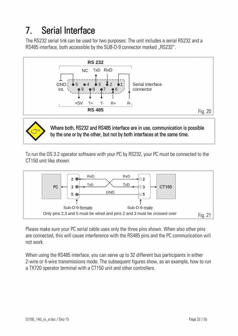
7. Serial Interface The RS232 serial link can be used for two purposes: The unit includes a serial RS232 and a
RS485 interface, both accessible by the SUB-D-9 connector marked „RS232“.
+5V
123459 8 67
NC
GNDint.
TxD RxD
T+ T- R+ R-
Serial interface connector
RS 232
RS 485 Fig. 20
Where both, RS232 and RS485 interface are in use, communication is possible
by the one or by the other, but not by both interfaces at the same time.
To run the OS 3.2 operator software with your PC by RS232, your PC must be connected to the
CT150 unit like shown:
Sub-D-9-female
RxD
TxD
RxD
TxD
GND
Sub-D-9-male
Only pins 2,3 and 5 must be wired and pins 2 and 3 must be crossed over
Fig. 21
Please make sure your PC serial cable uses only the three pins shown. When also other pins
are connected, this will cause interference with the RS485 pins and the PC communication will
not work.
When using the RS485 interface, you can serve up to 32 different bus participants in either
2-wire or 4-wire transmissions mode. The subsequent figures show, as an example, how to run
a TX720 operator terminal with a CT150 unit and other controllers.

Ct150_14d_oi_e.doc / Dez-15 Page 23 / 55
RS485 4-wire system
T-
TX720 CT150 Other device
1 8
R+ R- T+
Screen
2 x120 Ohm
R+ T-
6 7
T+ R- R+ R- T-T+
2 x120 Ohm
7 68 1
Fig. 22
RS485 2-wire system
TX720 CT150 Other device
8 7 T+ T-
120 Ohm120 Ohm
ScreenT+
T-
8 7
Fig. 23
A detailed description of the serial protocol is available upon request or can be downloaded
from the Download site of the motrona homepage www.motrona.com
(document name: „SERPRO“).

Ct150_14d_oi_e.doc / Dez-15 Page 24 / 55
8. Register settings Registers can be set by keypad under LCD control or by PC, using the OS3.2 operator software.
This section describes the registers and their meanings and the next section shows how to
program the registers.
The unit provides 4 Sub-Menus.
Data In Contains operational registers.
Setup Contains registers that need to be set only once upon commissioning.
Adjust provides easy setting of the analog gains upon commissioning.
Testprog executes various testing functions for internal and external signals.
The most important parameters can be edited or changed via the parallel interface.
All parameters and functions can be accessed via the serial interface.
Expressions like C00, C01 etc. indicate the serial register access codes.

Ct150_14d_oi_e.doc / Dez-15 Page 25 / 55
9. How to operate the Keypad (not needed with PC setup)
RunPCBA
LCD-Display
Processor
123456 78S1
PRG
PRG
Fig. 24
To access the operator PCB, remove right hand side plate. The on board setting controls
comprise an LCD display, 4 small buttons and a sliding switch. When the switch is selected to
"Run", the LCD permanently displays the software version of the program and the buttons A, B,
C and P have no function. Programming by the on board setting controls requires the sliding
switch to be slid to "PRG". For external PC setting it must however be in the „Run“ position.
The buttons have the following control functions (Cursor highlights the register):
Button A: Scrolls register down; scrolls menu forward and also increments
the highlighted digit.
Button B: Scrolls registers up; scrolls menu backward and also decrements
the highlighted digit.
Button C: Returns from register to menu titles; increments highlighted digits
to the right, (or from full right to full left).
Button P: Enters from menu to registers; changes register from text to value
and back to text again. Stores actual data to the EEProm.
After switching the sliding switch from “Run” to “PRG”, the display indicates “Data In” which
serves for parameter settings. By pressing the A key, the main menus are accessible ("Setup",
"Adjust" and "Testprog."). The following example shows how to set the “Trim“ register of the
Data In menu (see register table):
Action
LCD
Slide the switch to “PRG
DATA IN
Select the Data IN Menu by pressing “P“
Circ. 1
Press “A“ several times until the LCD shows “Trim“
Trim
Select the Trim register by P and read the actual setting
(i.e.100)
1 0 0

Ct150_14d_oi_e.doc / Dez-15 Page 26 / 55
Change setting to i.e. 050 ms like shown:
Key B decrements digit highlighted by cursor
0 0 0
Key C shifts cursor right
0 00
Key A increments highlighted digit. Press A 5 times
0 05
Press P to store the new value
Lenght
When you slide the switch back to “RUN“, you read again “CT15010A“ and the unit is ready to
operate. When you press “C“ instead, you come back to “DATA IN“ etc.
Please note:
The unit is unable to operate or to make serial communication while the slide
switch is in the “PRG“ position!
C00 Circ 1 C40 Mode Gain - Cor Mast - Dir
Data IN Set - up Adjust Testprog
C01 PPR 1 C41 LV - Calc Gain - Tot Slav - Dir
C02 Circ 2 C42 PI-Form Offs - Cor
C03 PPR 2 C43 Add-Cor Gain - Co rC04* Tr imm Offs - Tot
C05 Length
C90 Un it - Nr.
Gain - Tot
C06 Min. Len
C91 Baud - Rat
LED - POC07 Cu t -> P2
C92 Ser - FormCont - IN
C08 P1 -> Cut
C93 Bus-Add
PI - INC09 Cu t/Rev
C94 Bus-Baud
C10 Mark/Leng
C95 Bus-Config
C11 Foto -> Cut
C96 BusTxPar
C12* Pho-Offs
C97 BusRxPar
C13 Mark/Win
C45 Mast - Dir
Factory
C14 Cu t-Tol
C46 Slav - Dir
C15 AlertC47 Offs - Cor
C16 Cor-Divi
C48 Gain - Cor
C17 Ramptime
C49 Offs - To t
C18 Vmax/Vlin
C50 Gain - Tot
C19 Ind.Mode
C20 +/- Sync Rate
B
ACP
B A
B
Length CorLength/PulsePow Sens
Samp Time
Ramp Form
C21
C22C23
C24
C25
ACP
Fig. 25

Ct150_14d_oi_e.doc / Dez-15 Page 27 / 55
10. The Data IN – Menu
Register Description
Circ 1:
This register must be set to the circumference of the line feed roll or the
measuring wheel. You are free to set it in any dimensions (i. e. inch,
millimeters or 0.1 millimeters), but herewith you fix up all other length
dimensions (for other registers, length preset, photocell distance etc.) If you
enter Circ 1 with 0.1 mm resolution, all following presets will be scaled with
0.1 mm steps. Range 1 - 65535
PPR 1:
Pulses per revolution of the feed roll. Enter the number of pulses from the
master encoder for one revolution of the roll, or measuring wheel.
Range 1 - 999 999. Observe count setting (x1, x2, x4).
Circ 2: Circumference of the cutting roll. Range 1 - 65535 length units
PPR 2: Pulses per revolution of the cutting roll. Range 1 - 999 999
Trim:
Speed for positional displacement of the cutting position, when using the
Trim inputs. Entry is in software cycles (1 cycle = 100 sec) necessary to
displace the cutting roll by one slave encoder increment. With setting 001,
the unit changes the position by 1 encoder increment every 100 sec. With
setting 999 we need 999 x 100 sec to change the position by one increment.
Length:
This is a default length which the cutter will cut upon missing remote length
preset. It will also cut the default length whenever the slide switch is
returned from PRG to its RUN position.
Range 1 - 999 999 length units.
We recommend to set always this register similar to the Circ 2 register
(continuously synchronous roll speed).
min. Length:
Minimum cutting length. Limits the length setting range in order to avoid
operator mistakes
Cut P2:
This register defines, how long after the rising edge of the cutting pulse the
roll must remain synchronous before the speed profile starts to change speed.
Entry in length units.
Range 1 - 9999
P1 Cut: Similar to above, but distance prior to the rising edge of the cutting pulse.
Range 1-9999
P1 Cut P2
P1-Cut Cut-P2
Line speed
Roll speed
Cutting pulse Fig. 26

Ct150_14d_oi_e.doc / Dez-15 Page 28 / 55
Register Description
Cuts/Rev:
Set this register to 1 when your roll uses only one tool at it‘s circumference to
perform one only cut per revolution.
There are two ways of setting when you have mounted two or more tools
around the roll and one revolution performs two or more cuts.
a) You have one only cutting pulse per revolution of the roll (where i. e. two
cuts are executed). Then set this register to the number of cuts the roll
performs with each revolution. The CT 150 then will generate the missing
cutting pulses internally.
Example:Two cuts per revolu tion, but only one cuttingpulse: Set “Cur / rev.” to “2” Fig 27
b) You use several cuts per revolution, but each cut will also generate a
cutting pulse. Then proceed like follows:
Set register „Cut rev“ to 1
Do not set the real circumference to the register „circ 2“, but set it
only to the part of the circumference between two cuts.
Set also the ppr2 register to the number of pulses for one cut.
Example: Two cuts per revolution, but also two cutting pulses pe r revolution: Set “Cut / rev” to “1”.Set “circ2” to half of the real roll circumference.Set “ppr2” to half of the ppr. Fig. 28
Marks/Length: For print mark registration only:
Set this register to „1“, when you have only one print mark with each cut. Set
it to the number of print marks between two cuts, when you find several
marks, but the cut should only be executed with one specific mark.
Pho Cut:
With print mark registration only.
Preset of the mechanical distance between photocell and cutting position.
Range 0 - 999 999 length units.

Ct150_14d_oi_e.doc / Dez-15 Page 29 / 55
Register Description
Pho- Offset:
With print mark registration only.
Fine adjustment of the desired cutting position with respect to the print mark.
Setting to „0“ results in placement of the cut to the edge of the print mark
(rising edge of the photocell).
This register is also accessible remotely by parallel input. Range +/- 9999
length units.
Photo - > Cut
Cutting rollPhotocell
0Pho-Offs. Fig:29
Mark/Win: With print mark registration only. Defines a symmetric window around the
rising edge of the print mark sensor. The print mark is supposed to appear
inside this window and signals outside the window will not trigger the print
mark registration. See also input „Reset mark counter“.
Range 0-999 length units. You must set this register to 00 if not used.
Cut Tolerance:
Defines the switching level of the outputs „Cut too short“ and „Cut too long“.
Range 0-99 length units. Increments the waste counter and the cycle counter
for automatic length overwrite (with print mark mode) every time when
exceeded.
Alert:
Defines the switching level of the alarm outputs when the system is forced
out of synchronization due to external events (drive fault or mechanical
problem). Setting occurs in „error encoder increments“ and the alarm outputs
switch on when the positional error of the roll in respect to the scheduled
position overpasses the number of encoder bits set. Range 1 - 9999.
Cor-Divi:
Correction divider. Setting range 1-9. This provides a digital attenuation of
the phase correction signal that is produced, when the drive on mechanical
grounds (deadband or backlash) cannot respond. In such a case, it is not
desirable to make corrections immediately. The "Cor-Divi" provides a window
for the drive "backlash", within which the controller produces no correction.
Value 1 = No window, Reaction to 1 error increment.
Value 2 = Window +/- 1 Encoder increment.
Value 3 = Window +/- 2 Encoder increments.
Value 4 = Window +/- 4 Encoder increments.
Value 5 = Window +/- 8 Encoder increments. etc.

Ct150_14d_oi_e.doc / Dez-15 Page 30 / 55
Register Description
Ramp time: Ramp time to stop the cutter drive.
Range 0.01 – 9.99 sec.
This ramp has absolutely nothing to do with the ramps the unit uses in
normal operation, because it automatically calculates the softest speed
transition possible. The ramp register only stops the drive when you slide the
keypad enable switch from „Run“ to „PRG“ while the drive is running, or
when you use the Start/Stop input to stop the drive.
Vmax/Vlin:
This setting is important only when the range of cutting lengths includes
lengths shorter than the roll circumference, so the roll must accelerate
between two cuts. The register sets the maximum speed ratio between the
circumferential roll speed and the line speed that the drive will take when
required.
This means, whenever you cut shorter length, it is necessary the slave drive
can at least run double line speed. The higher the ratio, the shorter the
minimum length you can cut. It is important to know that this ratio setting
does not refer to the maximum line speed, but to the real line speed you use
when cutting short length. You are free to reduce your line speed with shorter
length preset and i. e. set this register to 8. But then you must be sure that
the cutter drive can really run 8 times the line speed you actually use for your
shortest length. In general, setting „8“ can be recommended.
Index Mode:
This register selects the index source (i. e. the cutting pulse and the print
mark pulse). You are free to use either the TTL inputs on the encoder
connectors, or the HTL inputs at the control IN / OUT port PI / PO.
Index Mode Cutting pulse source Print mark source
0 HTL, Pin 8
on PI/PO
HLT, Pin 20
on PI/PO
1 TTL Index Pins
6 and 7 at Slave input
HLT, Pin 20
0n PI/PO
2 HTL, Pin 8
0n PI/PO
TTL Index Pins
6 and 7 at Master input
3 TTL Index Pins
6 nnd 7 at Slave input
TTL Index Pins
6 and 7 at Master input
Fig. 30
+/- Sync Rate:
Percent adaptation of the circumferential roll speed to the line speed during
the synchronous cutting phase. Setting range +/- 99.9%. When set to 00.0%
(normal setting), the tool will be fully synchronous with the line upon the cut.
Some applications may require slightly higher or lower speed due to the
shape of the cutting tool, which can be set by this register.

Ct150_14d_oi_e.doc / Dez-15 Page 31 / 55
Register Description
Length
Correction:
With print mark registration only. Automatic overwrite of the length setting
by the print mark distance found by measurement. Setting range 0 – 9
0 = overwrite switched off
1 = overwrite after 1 cycle
2 = overwrite after 2 cycles
3 = overwrite after 4 cycles
4 = overwrite after 8 cycles
Clarification:
When cutting or printing paper or foils with print marks, the material can
shrink or stretch for reasons of tension, ambient temperature, humidity etc.
As a result, the distance between two print marks (i. e. also the cutting
length) will change and no more exactly match the preset length. Due to the
proportional control feature of the CT150 unit, this would also cause a slight
displacement of the real cutting position with respect to the print mark.
The „Length Correction“ register sets a number of cutting cycles where the
cut must be out of tolerance (register Cut-Tolerance) in always the same
direction and consecutively. When reached, the length preset is automatically
overwritten by the real length measured between the print marks and
proportional position errors are eliminated.
Length/Pulse:
Scaling factor for the auxiliary impulse output. Setting range 1 – 99 999
length units per impulse. If the whole system is calibrated in „Millimeters“
and the output should be used to count and totalize the line with integer
meters, set this register to 1000 to receive one impulse every meter
Power Sense:
0 = batch counters not stored in the EEprom upon power down
1 = batch counters stored in the EEprom
Sampling
Time:
Provides digital filtering of the feed forward signal generated from the line
encoder.
Range 0001 - 1000 msec. Normal setting 1 msec. recommended.
In applications where the line speed is very unsteady, settings like 10 or even
100 msec. can be advantageous for smoother motion of the rotating knife.
Please note that higher setting results in lower response with changes of the
line speed.
Ramp Form:
1 = speed profile with S-shaped polynomial ramps (suitable best for nearby
all servo drives)
2 = speed profile with straight linear ramps (sometimes preferable with big
DC drives)

Ct150_14d_oi_e.doc / Dez-15 Page 32 / 55
11. Setup Menu
Register Description
Mode:
Mode 1: Operation without print mark
Mode 2: Operation with print mark
Important hint: When you use never print mark operation, set Mode to “1“.
When you use always print mark operation, set Mode to “2“. Where you run
mixed production (sometimes with and other times without print mark): Set
Mode to “2“ and install a select switch to apply or remove the print mark
impulse to pin 20 of the Control IN/OUT port, according to actual need.
LV - Cal: Selects analog or digital Feed Forward mode
1 = Analog Feed Forward. Apply a 0 - 10 V signal proportional to line speed
to pin 6 of the analog connector.
2 = Digital Feed Forward. Leave pin 6 of the analog connector open. Unit
generates Feed Forward signal from master encoder.
Use always setting „2“, except you need analog feed forward for special
reasons.
PI - Form: Selects the input code of the parallel interface (PI):
0 = data entry with BCD code
1 = data entry with binary or hexadecimal code
Add - Cor:
Switches the internal summation of the analog correction signal on / off.
0 = off, open loop mode with no correction
1 = on, closed loop mode with correction superimposed
Must always be set to “1“ with regular operation!
Unit-Nr:
For serial operation only.
Allows entry of a device address between 11 and 99. It is not allowed to use
addresses containing a "0" (i. e. 20, 30, 40 etc.) as these are reserved for
collective addressing of several units. Factory setting “11“.

Ct150_14d_oi_e.doc / Dez-15 Page 33 / 55
Register Description
Baud Rate For serial operation only.
The following transmission rates can be selected:
Baud Rate Setting
0 9600 Baud
1 4800 Baud
2 2400 Baud
3 1200 Baud
4 600 Baud
5 19200 Baud
6 38400 Baud
Factory setting : = 0 Fig. 31
Ser- Form Ser-Form: For serial operation only.
The following formats of serial data can be selected:
Ser-Form Data bits Parity Stop bits
0 7 Even 1
1 7 Even 2
2 7 Odd 1
3 7 Odd 2
4 7 None 1
5 7 None 2
6 8 Even 1
7 8 Odd 1
8 8 None 1
9 8 None 2
Factory setting: 0 Fig. 32
Bus-Add,
Bus-Baud,
Bus-Config,
BusTxPar,
BusRxPar:
Only relevant for units with option “field bus interface” (CAN-Bus or
PROFI-Bus DP). See supplementary instructions for further information.
Mast Dir:
Direction of phase of the master encoder. Settings can be changed from „0“
to „1“ in order to change the direction of internal counting. Changing this bit
does the same as interchange of the A / B encoder channels. For correct
setting see section 16 „Steps for commissioning“.
Slave Dir: Similar to above, but for slave encoder.
Off-Cor: Digital setting of analog offset on correction signal.
Setting range +/- 99. Normal setting "0"*)
Gain-Cor: Digital setting of gain control (proportional control)
Range 0 - 9999. Setting to 9999 results in a response of 100 mV per error bit.
Recommended setting: 200....2000 (i. e. 2 mV....20 mV per error bit).

Ct150_14d_oi_e.doc / Dez-15 Page 34 / 55
Register Description
Offs-Tot:
Digital setting of the offset on the slave speed reference output.
Range +/- 99. Normal setting "0" *)
Gain-Tot:
Digital setting of the feed forward analog output gain. Setting range 0 –
999999. (see section 16 „Steps for commissioning”)
*) Remark:
CT150 uses precision instrumental amplifiers which do not need an offset
adjustment. In larger drive plants however, by balance currents between
several devices, an external offset can build up, which can be
compensated by the offset adjust. Normally both offset registers should
be set to “00”.
12. Adjust Menu There are only the parameters Gain-Cor and Gain-Tot accessible (the same as described above),
but in this menu they can be changed continuously with the motors running.
This allows easy adjustment of the analog synchronization and the intensity of correction while
observing the LED bar graph and the drives.
Keeping down key A continuously increments the values and key B decrements, while the LCD
displays the current state. The PRG key stores the setting to the EEProm and key C resets the
LED bar graph to its green centre position.

Ct150_14d_oi_e.doc / Dez-15 Page 35 / 55
13. Testprog – Menu This menu contains a couple of useful tests for the controller itself and its peripheral devices
(encoders, remote lines etc.)
Register Description
Mast-Dir:
This is the same register as in the setup menu, but the LCD display operates
as an up/down counter for the master encoder pulses, permitting full check of
the encoder functions. When the encoder is rotated "forward", the counter
counts up. If incorrect, press "A" to change the counting direction. Key "B"
operates as a counter reset button. Key "PRG" automatically stores the
direction in the “Mast-Dir” register.
Slave-Dir: Similar to Mast-Dir, but for slave encoder.
For testing of encoders and wirings we recommend the following procedure:
a) Reset the counter to “0”
b) Turn the corresponding encoder exactly one full revolution forward. The
display will show the number of the encoder pulses, independently from
the selected factors.
c) Now turn the encoder back to the original position.
The display must show „0“ again.
d) If this test does not work as described, you can be sure that the connection
is wrong (e.g. interchanged encoder channels) or the encoder is faulty.
Off-Cor: Similar to the setup menu, but continuous scroll up/down by keys "A" and "B"
and 100x increased resolution (100 mV output correspond to 1 mV in reality)
for better measuring.
Gain-Cor:
Similar to the setup menu, but continuous scroll up/down by "A" and "B" and
full scale correction output (1024 error bits are simulated).
Offs-Tot: Similar to setup menu, but scroll function with "A" and "B"
Gain-Tot: Similar to setup menu, but scroll function with "A" and "B"
LED + PO:
Test for front Led’s and Control outputs PI/PO. Switches on and off all Led’s
and outputs, one after the other.
Cont-IN:
Checks and displays the state of the PI/PO control inputs. The LCD display
shows the inputs in hexadecimal code (0...9, A, B, C, D, E, F). Touching key "A"
changes the code to "1 of 12" and the high state pin numbers of the connector
appear in the display. In this code, only one pin can be displayed.
PI-IN:
Displays the state of all data and select lines in a BCD or hexadecimal code.
Suited best to check data transmission from a remote switch or a PLC.
Factory: Hidden registers, factory accessible only.

Ct150_14d_oi_e.doc / Dez-15 Page 36 / 55
14. The LED Display The 8 LEDs mounted on front of the module indicate the instantaneous angular error between
the real roll position and the position where it should be with respect to the actual line
position. The display provides information for commissioning and fault monitoring, in a very
simple but efficient form.
red
orange
yellow
green
green
256 +++
128 - 255
64 - 127
32 - 6316 - 31
8 - 15
1 - 7
+ / - 0
1 - 7
8 - 1516 - 31
32 - 6364 - 127
128 - 255
256 +++
yellow
orange
red
Fig. 33
When both green Led’s in the centre are lit, the phase error is absolutely zero.
When either of the green Led’s is lit alone, the error lies between 1 to 7 bits. When one green
and one yellow LED is lit, the phase error lies between 8 to 15 bits, etc.
When the lights are up, this indicated positive correction (Master is ahead)
When the lights are down, this indicated negative correction (Slave ahead)
The above notes hold for positive reference giving forward rotation. Everything is reversed for
negative reference giving forward rotation.

Ct150_14d_oi_e.doc / Dez-15 Page 37 / 55
15. Criteria for Drives, Encoders, Cables, Installation
15.1. Construction of the drives The drives in use must be dimensioned correctly in respect to power and dynamics required.
The CT150 can never provide good operation outside the physical limits of the drives. Prior to
connecting the master and the slave to the controller, both drives must be adjusted for a proper
stand-alone operation with no oscillation, by means of a remote speed reference voltage. The
reference inputs must be potential free.
15.2. Encoder resolution The resolution of the TTL-encoders, in principle, should be as high as possible, in order to keep
the mechanical phase error as small as possible when the controller "plays" a few encoder
increments around the zero error position. However it would be nonsense to choose the number
of ppr much higher than needed or reasonable. If, for example, a gear box with several 0.1 mm
of clearance is installed, a 0.01 mm resolution of the encoder could cause slight stability
problems, which needed to be removed by the "Corr-Div" error divider again.
The CT150 loads each encoder channel with a current of 15 mA. For this reason, one encoder is
unable to supply the impulse input of several target units at a time, as needed with some multi
drive systems. In such applications, our impulse distributor type GV150 must be used to feed
several controllers from one encoder.
Encoder
GV150 3
2
1
4
56
(cascadable)IN OUT
Fig. 34
15.3. Encoder lines Please note, that not all types of cables are suited to transmit frequencies as high as 300 kHz!
However, with proper installation and screening, the RS 422 lines provide perfect transmission
even over long distances.
The cross section of encoder cables must be chosen with consideration of voltage drop on the
line. The CT150 provides a 5.2 V encoder supply and at the other end the encoder must at least
receive it‘s minimum supply voltage!
Please observe the unit accepts at maximum 300 kHz of encoder frequency.

Ct150_14d_oi_e.doc / Dez-15 Page 38 / 55
15.4. Wiring and shielding You must strictly observe all rules and specifications given in the drive manual and all general
safety and installation standards (see chapter 1). Use shielded power cables for the motors.
Keep distance between power cables and electronic cables. Put filters to all inductive
equipment installed in the same cabinet (i.e. RC filters in parallel to coils of AC contactors,
diodes in parallel to electromagnetic DC values etc.) Make sure your cabinet and your machine
have a solid earthing/grounding system. CT150 possesses excellent features with EMC
immunity, but it can fail under poor electrical environment conditions.
Keep strictly to the instructions for screening given in chapter 5!
15.5. Relay contacts If you need to switch electronic signals by relay contacts, it is necessary to use relays with gold
contacts. For impulse or analog switching, we recommend the use of our electronic matrix
switch type GV155.
16. Steps for commissioning In principle, all commissioning could happen without a PC, just by use of LCD and keypad.
Since, however, things go much easier and faster, we recommend you to use the
OS3.2 operator software and follow the subsequent steps.
16.1. Presetting’s At this time you must be sure your cutting roll drive is adjusted for proper operation and
maximum dynamics.
Remove any ramps and delays from the drive because the CT150 controller will produce the
ramps. Make sure the drive can run the maximum speed with a speed reference of 9 Volts
already (We must leave 1 Volt of output swing for the CT150 to make corrections).
16.2. Connections and DIL settings Make sure all connections are correct and DIL switch S1 is set according to need.
You must be sure your cutter drive runs forward (direction of the line) when is
receives a positive voltage. If not, you must change this on your drive now.

Ct150_14d_oi_e.doc / Dez-15 Page 39 / 55
16.3. Starting the Operator Software Power the unit up, connect the serial cable to the PC and start the OS3.2 software.
Fig. 35
16.4. Parameter settings Set all registers according to need.
The following registers must be set to initial values like shown:
Length : = Circ 2 Mode : 1
Fig. 36
Corr-Divider : 1 Add Cor : 1
Vmax : 8 Gain Cor : 200
+/- Sync : 00.0 Gain Tot : see table
Unit NR. : 11
Baud Rate : 0
Ser Form : 0
The initial Gain Tot setting depends on the expected maximum frequency of the line encoder
(frequency in KHz at maximum line speed)
fmax Gain Total
Fig. 37
1 kHz 200 000
3 kHz 66 000
10 kHz 20 000
30 kHz 6 600
100 kHz 2 000
For frequencies between use interpolated values.
Initial setting can be approximately.
Setting of registers “Mast-Dir“ and “Slave-Dir“ is not important at this time.
Click “Transmit All“ and then to “Store EEProm“ to store your settings to the CT150 controller.

Ct150_14d_oi_e.doc / Dez-15 Page 40 / 55
16.5. Define the counting direction We must first set the counting direction of the encoders.
Select the “Test“ function in the “Tools“ menu.
Fig. 38
Click to the “Master Direction“ field. Rotate the Master encoder in forward direction, e.g. the
direction it will rotate later with the material. The counter in the Master Direction field must
count up. Where you find we count down, click “Change direction“.
When we count up, click to the “Direction Slave” field.
Warning: The cutter drive will get a speed reference of 2 Volts via ramp while
you click. It will start immediately when the drive is enabled! This test speed
depends on the Gain-Correction setting (200 = 2 Volts) and you can reduce it if
required for this test. However, for further steps it is necessary to set Gain-
Correction to 200 again.
Also the “Direction Slave” counter must count up. Where you find we count
down, click “change direction“. When we count up, click to any other field to
stop the carriage drive again.

Ct150_14d_oi_e.doc / Dez-15 Page 41 / 55
16.6. Transmit parallel data Where you use the parallel interface for length preset (e.g. with a remote BCD switch or a
PLC data output), please click to the “Parallel Interface“ field and verify the parallel data arrive
correctly.
16.7. Control input checking Click “Exit“ now to return to the normal screen. This will save the settings in the controller.
Next, you should check if the control inputs you use operate correctly. Apply all signals like
“Reset“ or “Start/Stop“ and see if the signal change is visible in the “external“ column of the
Inputs field of your screen. Especially it is important to check the ”Cutting Pulse”. The
corresponding indication box in the external field must go either ON or OFF while your tool is
approximately in it’s cutting position. Please remind the Cut-P2 and P1-Cut settings refer to the
rising edge of the cutting pulse (when indicator switches from ”OFF” to ”ON”).
16.8. Analog Gain adjustment As a next step, we must set the “Gain Total” value for the analog feed forward signal. Make
sure the cutter drive is enabled to run, then select the “Adjust“ function in the “Tools“ menu.
Please run the Master encoder at low speed and see how the cutter roll follows.
Fig. 39

Ct150_14d_oi_e.doc / Dez-15 Page 42 / 55
We must observe the color bar graph and the differential counter now while we adjust the
“Gain Total“. Gain Correction should always be set to 200 during this procedure.
When we click the Reset to “ON“, our differential counter will show zero and the bar graph will
be in its green center position.
When we click the Reset to “OFF“, our differential counter will run away and the bar graph will
move to one or the other direction.
We must find now a setting for Gain Total that keeps our counter close around zero
(i.e. -5....0....+5) and the bar graph in its green/yellow center position.
When the counter counts to positive (bar graph moves to right):
Gain Total is too low and must be increased.
When the counter counts to negative (bar graph moves to left):
Gain Total is too high and must be reduced.
For important changes of Gain Total use the slide button in the Gain Total field.
For fine tuning, use the and buttons.
16.9. Gain Correction adjustment When Gain-Total has been set correctly, we must now adjust Gain-Correction. The rule is to
have Gain Correction as high as possible. Typical values are from 300 to 1000, sometimes even
2000. Where you find your drive starts oscillating or running roughly, reduce Gain Correction
again until we have stable operation. To change Gain-Correction, use the slide button or the
and keys of the corresponding field.
16.10. Cutting cycle simulation We now can exit the Adjust Menu and return to the main menu. The machine is ready to cut
and we can simulate automatic cutting cycles.
It is important you start your first trials with a length setting equal to the circumference 2 -
setting. This ensures your cutting roll rotates at constant speed with the circumferential tool
speed always synchronous to the line. Then try to change the length setting. The more your
settings moves away from the „“circ2“ value in one or the other direction, the more distinct you
will see the speed profile of the cutter roll. All the time, the front LED’s on the unit and the
color bar on the PC screen should move around the green/yellow center range.

Ct150_14d_oi_e.doc / Dez-15 Page 43 / 55
16.11. Visualize a cutting cycle by the OS3.2 It is recommendable to observe the cutting cycle by the oscilloscope function of the operator
software. Select ”Oscilloscope” in the Tools menu. Set the serial code of channel 1 to :1 to
see the cutting error. Set the serial code of channel 2 to :2 to see the speed profile.
Fig. 40

Ct150_14d_oi_e.doc / Dez-15 Page 44 / 55
17. Hints to improve performance The performance of the electronic control system is clearly indicated by the front LED’s and the
color bar with differential counter on your PC screen. When you have achieved settings to keep
the LED’s at the green/yellow center position at all line speeds and with all length presets,
there is nothing to improve.
If, despite of this, your cutting results should not satisfy you in terms of accuracy or
synchronism, there are definitely mechanical or other reasons outside of the control loop.
The following hints refer to improvements you can make when LED and differential counter
indicate unusual characteristics:
Many of the front LED’s are lit at the same time and the differential counter shows very
unstable values:
The resolution (ppr per length unit) of one of the encoders could be much higher than
the mechanical clearance of your gears / tooth wheels etc.
reduce edge count setting from (x4) to (x2) or (x1)
See register ”Correction Divider”
Reduce “”Gain Correction” setting if this eliminates the problem.
Remark: Even though your LED’s can indicate a very unstable characteristics, your
cutting accuracy and performance may be good. Then just accept this visual flaw.
The LED’s and the differential counter move up and down with the speed cycle of the cutter.
Try to increase the “Gain-Correction“ setting
Check for avoidable ramps and delays in your drive
The cutter drive is not strong and dynamic enough to follow the speed profile or to bring
enough torque at the time the tool penetrates the material
Reduce line speed for length settings where you observe this.
Remark: This must not really affect your cutting performance.
When the accuracy is good, you can accept this visual flaw.

Ct150_14d_oi_e.doc / Dez-15 Page 45 / 55
18. Auxiliary Register and Command Codes The following auxiliary registers are accessible by serial link, with the access codes shown
(R = Read only, R/W = Read and write)
Code Name Function
:1 Error Count (R) Shows the differential number of encoder increments
between the scheduled roll position and the real roll
position at any time
:2 LV Value (R) Represents the actual feed forward signal (speed profile)
of the cutting roll drive.
0 = Standstill 4095 = maximum speed.
:6 Print mark Error (R) Difference between actual and desired position of the
cut with respect to the print mark. Unit: master
encoder increments. (Only available when Mode = 2)
:7 Batch Counter (R/W) Increments with every cut executed. Can be preset to
zero or datum.
:8 Waste Counter (R/W) Increments with every “Out of tolerance“ cut. Can be
preset to zero or datum.
:9 Line Speed (R) Represents the encoder frequency of the measuring
wheel. 1 bit = 5Hz.
<4 Actual Cutting Length (R) Actual cutting length, scaled in master encoder
increments
<7 Actual Cutting Error (R) Actual cutting length minus preset cutting length, scaled
in master encoder increments
<8 Actual Cutting Error (R) Actual cutting length minus preset cutting length, scaled
in length units

Ct150_14d_oi_e.doc / Dez-15 Page 46 / 55
Beside the serial access codes shown in this manual, the subsequent codes are available to
execute the same commands that can be activated by the hardware inputs also:
Ser. Code Bit of control word (86) Function Type
Fig. 41
55 14 Reset mark counter S
56 4 Read PI data D
58 0 Start / Stop S
60 7 Reset S
65 6 Trim + S
66 5 Trim - S
67 3 Activate data D
68 1 Store EEProm D
S = Static command, must be set to 1 to activate command and must be reset
to 0 to deactivate command.
D = Dynamic command, must be set to 1 to activate command. Is
automatically reset to 0 after execution.
All commands can be activated either by its serial access code or by setting the corresponding
bit of the control word (Ser. Access code 86).
Please note that all serial commands are “logical OR” to hardware commands
(control inputs) and hence a command is ON whenever set by serial command
or hardware input or both at a time.
The state of the control outputs can be read out by the status word (Ser. Access code 85) via
serial interface. Bit 7, 6, 5, …, 1, 0 of the status word correspond to control outputs PI/PO pin
5, 17, 4, 16, 3, 15, 2, 14.
For further details please see the separate manual of the “Drivecom protocol” which can be
requested at any time from motrona.

Ct150_14d_oi_e.doc / Dez-15 Page 47 / 55
19. General Master Reset and Erase of EEProm The unit carefully checks all entry data for validity and correctness within their permitted
numeric range. If, as an extreme exception, invalid data should intrude into the register range,
bad function or even a full hang-up could be the result. If this should ever happen
push the Reset button on the unit‘s front (accessible by a small screw driver only)
or
power down the unit and power up again after a few seconds.
Both measures result in a complete reconfiguration of all ports and registers. RAM
and buffer data will be lost and the unit restores all data from the EEProm.
If, however, invalid data should have penetrated to the EEProm, even the previous
steps will not help. In this case:
switch off the unit
set the slide switch PRG/RUN to the PRG position
keep key A down while powering on the unit and keep it down for at least
another 5 sec.
This will clear up all the EEProm to its factory default values, and all registers need to be setup
once more.
Above steps represent an emergency procedure that you will never have to
apply under regular conditions. In an extreme case however (i. e. lightening-
strike in the factory etc.) they could help to get the unit working again.
It is mandatory to erase the EEProm when the processor has been changed for
reasons of software upgrade.
20. Physical Range of Cutting Lengths The possible range of cutting lengths depends on several mechanical and electrical parameters
like roll diameter, line speed, synchronous zone and dynamics of the drive. There is no
limitation from the CT 150 controller. This unit calculates at any time the longest ramps
possible to achieve the desired cutting result. As soon as these ramps become so short that the
drive is unable to follow, we run to the physical limit.
The subsequent formulae should help you to optimize the layout of your cutting machine or to
calculate what is possible or impossible. It is assumed that the cutter drive could run 8 times of
maximum line speed (Vmax / Vmin = 8).

Ct150_14d_oi_e.doc / Dez-15 Page 48 / 55
In situations where the cutter can take higher speeds, or where we can reduce line speed at
extremely short cutting lengths, it is possible to cut shorter pieces than given by the formulae.
The following abbreviations are used:
U = Circumference of the cutting roll (mm). v0 = Max. line speed in mm per second.
sync = length of the synchronous phase (mm)
tH = Shortest time the drive needs to accelerate the roll from line speed to
double line speed (sec.).
t L = Shortest time the drive needs to decelerate the roll from synchronous
speed to standstill (sec.). = Actual cutting length (mm).
L1, L2, T1, T2 = Reference values for calculation.
20.1. The shortest possible length The smallest possible cutting length depends (inter alia) on the peripheral speed of the blade
cylinder - compared to the line speed. The following formulas assume, that the blade cylinder
can rotate up to 8 times faster in the given operating situation than the line (Vmax / Vmin = 8).
If this is not ensured, corresponding higher values for the minimum cut length are the result.
First we must calculate the reference time T1:
T1 secU
9 v
sync
0
When tH is lower or equal T1:
min
8
7 0l v t Usync Hmm
When t H is higher than T1:
min sync 0 H 0
2
H
2
sync 0 Hv t v t U v t 27
27
7 mm
20.2. The longest possible length
First we must calculate the reference time T2:
T2 =U -
v
sync
0
When tL is lower or equal T2, there is no limitation for long lengths.
When tL is higher than T2, the longest length is:
max sync 0 L 0
2
L
2
sync 0 L2 v t 2 v t U v t mm

Ct150_14d_oi_e.doc / Dez-15 Page 49 / 55
20.3. Dynamic requirements for the roll drive The subsequent formulae show what the drive must be able to execute in terms of acceleration
/ deceleration, when the cutting parameters are specified. To differ between the different types
of the cutting profile, it is necessary to calculate two reference length values. Further it is
assumed that the drive in extreme cases is able to operate still with the 8-fold line speed.
First we need to calculate two reference length values:
mmmm sync
sync2UL2
9
U2L1
7
For all cutting lengths smaller or equal L1:
secv7
71-81t
0
sync
H
U
For all cutting lengths longer or equal L2:
secv
Ut
0
sync
L
For lengths between L1 and L2 we get:
Uv4
1t
2
sync
0
L
Uv4
7t
2
sync
0
H

Ct150_14d_oi_e.doc / Dez-15 Page 50 / 55
21. BY 106-X Remote Thumbwheel Switch
BY106
1 2 3 4 5 6 7 8 9 1011 12
1 2 3 4 5 6 7 8 9 1011 12
max. 1,5X2
X1
DEC.1 DEC.2 DEC.3 DEC.4 DEC.5
X2
X1
2 Screwt erminals,12 positions each
72,5mm
24 mm
23 mm
A
B
Panel Cut Out
Switch Type No. Decades A (mm) B (mm)
BY 106-3 3 59,5 57
BY 106-4 4 59,5 57
BY 106-5 5 74,5 72
Fig. 42
+24V *1
S1 14S2 2S3 15S4 3
164
175
186
197
208
219
22102311
24122513
BCD1 BCD2 BCD4 BCD8
X2/3X1/3X2/4X1/4
BCD1 BCD2 BCD4 BCD8
BCD1 BCD2 BCD4 BCD8
BCD1 BCD2 BCD4 BCD8
BCD1 BCD2
BCD4 BCD8
X2/5X1/5X2/6X1/6
X2/7X1/7X2/8X1/8
X2/9X1/9X2/10X1/10
X2/11X1/11X2/12X1/12
X2/1
(LSD)
10-4
10-3
10-2
10-1
10-0
(MSD)
Remoteswitch typeBY 106-5orPLC Control
CT 150(PI)
Select-lines
Switch supply*
SUB-D-Connector 25-pin ScrewterminalScreen
Fig. 43

Ct150_14d_oi_e.doc / Dez-15 Page 51 / 55
22. Technical Specifications
Power supply: Input voltage:
Protection circuit::
Consumption:
Connections:
18 … 30 VDC
reverse polarity protection
approx. 300 mA (unloaded)
coded plug connector, 2-pin
Encoder supply: Output voltage:
Connections:
5.2 VDC / max. 400 mA
SUB-D connector (male), 9-pin
General data: Control cycle:
Cutting accuracy:
Data memory:
Error memory:
approx. 150 µs
approx. +/- 5 encoder increments
EEProm (min. 10 years)
32 000 error increments
Incremental inputs: Number of inputs:
Characteristic:
Signal levels:
Channels:
Frequency:
Internal resistance:
Connections:
2
5 V-TTL / RS422 (optically isolated)
LOW: 0 …0.8 V, HIGH: 3 … 5 V,
resp.. 4 … 5 V with differential operation
RS422: differential voltage > 3 V
A, /A, B, /B and (selectively) Z, /Z
max. 310 kHz
Ri ≈ 1.5 kOhm
SUB-D connector (male), 9-pin
Control inputs: Number of inputs:
Signal levels:
Characteristic:
Internal resistance:
Min pulse time:
Connections:
12
LOW 0 … 3 V, HIGH 11 … 30 V
PNP / active high
Ri ≈ 12.7 kOhm
1 ms
SUB-D connector (female), 25-pin
Analog inputs: Number of inputs:
Input voltage:
Resolution:
Connections:
3
+/- 10 V
12 bit (4096 steps)
SUB-D connector (female), 9-pin
Parallel interface: Number of inputs / function:
Format:
Signal levels:
Characteristic:
Connections:
1 parallel port (24 bit) for transfer of 6 parameters
BCD or binary (switchable)
LOW 0 …5 V, HIGH 18 … 30 V
PNP / active high
SUB-D connector (male), 9-pin
Control outputs: Number of outputs:
Characteristic:
Output current :
Connections:
8 transistor outputs (optically isolated)
PNP, 10 … 30 V (depends on voltage at the COM+ input)
max. 30 mA
SUB-D connector (female), 25-pin
Analog outputs: Number of outputs:
Output voltage:
Resolution:
Accuracy:
Connections:
3
each +/- 10 V, max. 5 mA
12 bit (4096 steps)
0,1 %
SUB-D connector (female), 9-pin
Serial interface: Format:
Baud rate (switchable):
Connections:
RS232 & RS485 (2- or 4-wire), CAN-Bus as an option,
PROFIBUS by using the motrona converter unit “PB251”
600, 1200, 2400, 4800, 9600, 19200, 38400 bauds
SUB-D connector (male), 9-pin

Ct150_14d_oi_e.doc / Dez-15 Page 52 / 55
Continuation “Technical Specifications”
Housing: Material:
Mounting:
Dimensions (w x h x d):
Protection class:
Weight:
Galvanized sheet steel housing with an aluminum front-plate
Standard: 19"rack / Option SM150: for snapping on 35 mm top
hat rail (according to EN 60715)
4TE x 3HE resp. 70 x 129 x 175 mm / 2.756 x 5.079 x 6.890 inch
IP20
approx. 850 g
Temperature range: Operation:
Storage:
0 °C … +45 °C / +32 … +113 °F (not condensing)
-25 °C … +70 °C / -13 … +158 °F (not condensing)
Conformity &
standards:
EMC 2004/108/EC:
Guideline 2011/65/EU:
EN 61000-6-2, EN 61000-6-3, EN 61000-6-4
RoHs-conform
23. Dimensions
171
188
194
750
111
9
Side view
7
14
70
14
Top view
12
3
1
2
3
4
5
6
7
8
RES
ANALOGSLAVEMASTER
RS232
PI
PI/PO
70,555,5
122,5
128,6
Front view
Rear view
2,55,5

Ct150_14d_oi_e.doc / Dez-15 Page 53 / 55
24. Serial code list
24.1. Parameters
# Menu Name Code Min Max Default
0 DATA-IN Circumference 1 00 1 65535 1000
1 Pulses per Rev. 1 01 1 999999 10000
2 Circumference 2 02 1 65535 1000
3 Pulses per Rev. 2 03 1 999999 10000
4 Trim Time 04 0 999 100
5 Length 05 1 999999 1000
6 Minimal Length 06 1 50000 500
7 Cut -> P2 07 1 9999 10
8 P1 -> Cut 08 1 9999 10
9 Cuts / Revolution 09 1 99 1
10 Marks / Length 10 1 99 1
11 Photo -> Cut 11 0 99999 0
12 Photo-Offset 12 -9999 9999 0
13 Mark-Window 13 0 999 0
14 Cut-Tolerance 14 0 99 10
15 Alert 15 0 9999 100
16 Corr.-Divider 16 1 9 1
17 Ramp Time 17 0 999 0
18 Vmax / Vline 18 2 8 8
19 Index-Mode 19 0 3 0
20 +/- Synchron Rate 20 -999 999 0
21 Length Correction 21 0 9 0
22 Length / Pulse 22 1 65535 100
23 Power Sense 23 0 1 0
24 Sampling Time 24 1 1000 1
25 Ramp Form 25 1 2 1

Ct150_14d_oi_e.doc / Dez-15 Page 54 / 55
# Menu Name Code Min Max Default
26 SET-UP Mode 40 1 2 1
27 LV-Calculation 41 1 2 1
28 PI-Format 42 0 1 0
29 Add-Correction 43 0 1 1
30 Ser. Unit Number 90 11 99 11
31 Ser. Baud Rate 91 0 6 0
32 Ser. Data Format 92 0 9 0
33 Bus Address 93 1 127 1
34 Bus Baud Rate 94 0 7 1
35 Bus Config. 95 0 255 1
36 Bus Tx Parameter 96 0 255 0
37 Bus Rx Parameter 97 0 255 0
38 Master Direction 45 0 1 0
39 Slave Direction 46 0 1 0
40 Offset Correction 47 -99 99 0
41 Gain Correction 48 0 9999 100
42 Offset Total 49 -99 99 0
43 Gain Total 50 0 999999 2000
24.2. Inputs
# Name Code Cmd Bit SerStatus BusStatus ExtStatus
0 Reset 60 0080 Yes Yes Yes
1 Trim + 65 0040 Yes Yes Yes
2 Trim - 66 0020 Yes Yes Yes
3 Read PI 56 0010 Yes Yes Yes
4 Activate Data 67 0008 Yes Yes Yes
5 Program 1/2 0004 No Yes Yes
6 Store EEPROM 68 0002 Yes Yes Yes
7 Start / Stop 58 0001 Yes Yes Yes
8 Reset Mark-Cnt. 55 4000 Yes Yes Yes
9 Cutting Pulse 2000 No Yes Yes
10 Marker Pulse 1000 No Yes Yes

Ct150_14d_oi_e.doc / Dez-15 Page 55 / 55
24.3. Variables
# Name Code Notes
0 tstcou ":0" Internal Using
1 Error Count ":1" R(*)
2 LV Value ":2" R
3 Marpufh ":3" Internal Using
4 len_imh ":4"
5 Facdelh ":5"
6 Printmark Error ":6" R
7 Batch Counter ":7" R/W(**)
8 Waste Counter ":8" R/W
9 Line Speed ":9" R
10 mar_onh ";0" Internal Using
11 Cystah ";1"
12 Marcouh ";2"
13 Cutcouh ";3"
14 m_averh ";4"
15 Marmaxh ";5"
16 Marminh ";6"
17 mark_1h ";7"
18 mark_2h ";8"
19 mark_3h ";9"
20 mark_4h "<0"
21 mark_5h "<1"
22 Speed "<2"
23 mar_err "<3"
24 Actual Cutting Lenght "<4" R
25 mar_ofh "<5" Internal Using
26 Lenpufh "<6"
27 Actual Cutting Error (Scaling: Master encoder increments) "<7" R
28 Actual Cutting Error (Scaling: length units) "<8" R
29 h'0000 "<9" Internal Using
30 varaddh "=0"
31 h'0000 "=1" (*) Read only
(**) readable and writable