Embed Size (px)
Citation preview

Operating Manual
Control and Power Unit
DCE 1500
Please read the operating manual before any operation!
2
© Emhart Teknologies TUCKER GmbH
Max-Eyth-Straße 1
D-35394 Gießen
Tel.: +49 (0) 641 405 0
Fax.: +49 (0) 641 405-383
E-Mail: [email protected]
Internet: www.tucker.de
Translation of the Original Operating Manual BTA DCE1500 01/10
Control and Power Unit DCE 1500
Table of Contents
3
Table of Contents
1 General Information....................................................................................................5
1.1 Information Regarding the Operating Manual ...................................................5
1.2 Limitation of Liability..........................................................................................5
1.3 Symbol Legend .................................................................................................6
1.4 Copyright Protection..........................................................................................7
1.5 Replacement Parts............................................................................................7
1.6 Guarantee Instructions......................................................................................8
1.7 After Sales Service............................................................................................8
2 Safety .........................................................................................................................9
2.1 Responsibility of the Operating Company.........................................................9
2.2 Personnel Requisition .....................................................................................10
2.2.1 Qualification........................................................................................10
2.2.2 Trespassers........................................................................................11
2.2.3 Instruction...........................................................................................11
2.3 Intended Use...................................................................................................12
2.4 Personal Protective Equipment.......................................................................13
2.5 Special Risks...................................................................................................14
2.6 Safety Devices ................................................................................................15
2.6.1 Operator Protection ............................................................................15
2.6.2 Interruption of Operation ....................................................................15
2.7 Securing Against Resetting.............................................................................16
3 Technical Specifications...........................................................................................17
3.1 General Specifications ....................................................................................17
3.2 Connected Loads ............................................................................................17
3.3 Fuse Elements ................................................................................................19
3.4 Dimensioned Drawing .....................................................................................21
3.5 Type Plate .......................................................................................................22
4 General Description..................................................................................................23
5 Assembly and Connections......................................................................................24
5.1 Layout DCE 1500............................................................................................24
5.1.1 Main Switch ........................................................................................25
5.1.2 Key Switch Maintenance Operation ...................................................25
5.1.3 LED Fuses..........................................................................................25
5.1.4 Connection PC / Laptop RS 232 ........................................................25
5.1.5 Connection Control terminal...............................................................26
5.2 Layout Inside of the Device.............................................................................27
5.2.1 Connection Power Supply ..................................................................28
5.2.2 Connection Safety Circuit X2 .............................................................28
Control and Power Unit DCE 1500
Table of Contents
4
5.2.3 Connection of Measurement Lines A1-X8 SF1 - A1-X12 SF5........... 28
5.2.4 Connection Weld Cables A1-X2 SF1 - A1-X6 SF5 ............................ 29
5.2.5 Connection Control Cables X3 SF1 - X7 SF5.................................... 29
5.2.6 Connection Ground Cable A1-X1 ...................................................... 30
5.2.7 Connection Ground-Measurement line A1-X7 ................................... 30
5.2.8 Connection of customer interface X8................................................. 31
5.3 Layout 1: DCE in standard operation.............................................................. 32
5.4 Layout 2: DCE in SD 2 Operation................................................................... 33
5.5 Layout 3: DCE with PKE................................................................................. 34
6 Display- and Control Elements................................................................................. 35
7 Conversion from Keypad to Touchpad..................................................................... 36
8 Notes Regarding Stud Welding................................................................................ 38
9 DCE 1500 Start-Up .................................................................................................. 39
10 Transport, Packaging and Storing ........................................................................... 41
10.1 Security Advice for the Transport .............................................................. 41
10.2 Transport Check ........................................................................................ 42
10.3 Transport ................................................................................................... 42
10.4 Terms and Conditions for Overseas Transport.......................................... 44
10.5 Packaging .................................................................................................. 45
10.6 Storing ....................................................................................................... 45
11 Maintenance and Cleaning ...................................................................................... 46
11.1 Safety......................................................................................................... 46
11.2 Maintenance and Cleaning Schedule ........................................................ 46
11.3 Cleaning of the Filter Insert........................................................................ 47
12 Disposal ................................................................................................................... 48 Appendix: EC- Declaration of Conformity
Control and Power Unit DCE 1500
General Information
5
1 General Information
1.1 Information Regarding the Operating Manual
This operating manual contains important information regarding the handling of
this device. The compliance with all security advisories and operation instructions
is a precondition for a safe operation.
Furthermore the local accident prevention regulations and the general safety
regulations effective for the application area of the device have to be observed.
Please read the operating manual carefully before any operation! It is a part of the
product and has to be stored in an accessible location in the direct vicinity of the
device for use by the appropriate personnel.
1.2 Limitation of Liability
All instructions and information in this operating manual have been compiled in
consideration of the valid standards and regulations, the state of the art as well as
our experience of many years.
The manufacturer assumes no liability for damages due to:
Non-observance of the operating manual.
Not intended use.
Employment of unskilled personnel.
Arbitrary rebuilding.
Technical modifications.
Use of non-licensed replacement parts.
On special design, on demands of additional order options or due to latest
technical modifications the actual shipment may differ from the explanations and
expositions described here.
Effective are the obligations agreed in the supply contract, the general terms and
conditions as well as the delivery conditions of the supplier and the legal
regulations valid to the time of conclusion of the contract.
Technical modifications within the improvement of the usage properties and the
further development are reserved.
Control and Power Unit DCE 1500
General Information
6
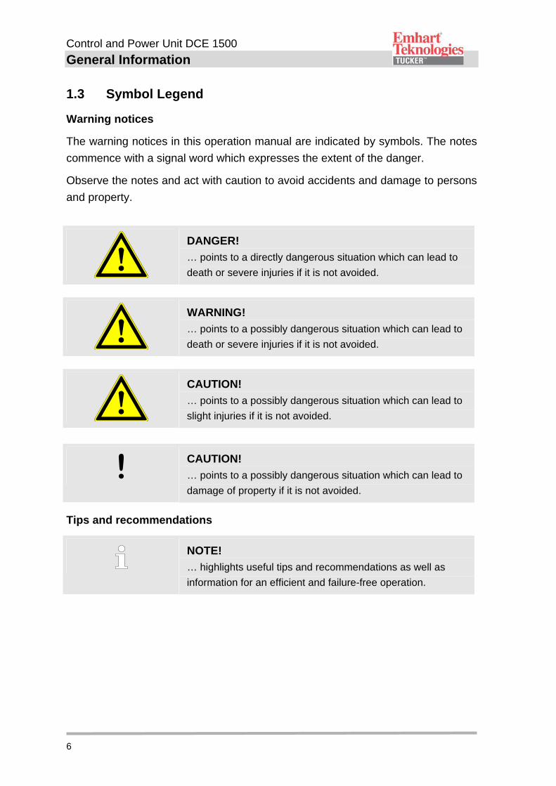
1.3 Symbol Legend
Warning notices
The warning notices in this operation manual are indicated by symbols. The notes
commence with a signal word which expresses the extent of the danger.
Observe the notes and act with caution to avoid accidents and damage to persons
and property.
DANGER!
… points to a directly dangerous situation which can lead to
death or severe injuries if it is not avoided.
WARNING!
… points to a possibly dangerous situation which can lead to
death or severe injuries if it is not avoided.
CAUTION!
… points to a possibly dangerous situation which can lead to
slight injuries if it is not avoided.
! CAUTION!
… points to a possibly dangerous situation which can lead to
damage of property if it is not avoided.
Tips and recommendations
NOTE!
… highlights useful tips and recommendations as well as
information for an efficient and failure-free operation.
Control and Power Unit DCE 1500
General Information
7
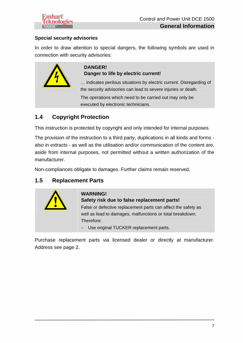
Special security advisories
In order to draw attention to special dangers, the following symbols are used in
connection with security advisories:
DANGER! Danger to life by electric current!
… indicates perilous situations by electric current. Disregarding of
the security advisories can lead to severe injuries or death.
The operations which need to be carried out may only be
executed by electronic technicians.
1.4 Copyright Protection
This instruction is protected by copyright and only intended for internal purposes.
The provision of the instruction to a third party, duplications in all kinds and forms -
also in extracts - as well as the utilisation and/or communication of the content are,
aside from internal purposes, not permitted without a written authorization of the
manufacturer.
Non-compliances obligate to damages. Further claims remain reserved.
1.5 Replacement Parts
WARNING! Safety risk due to false replacement parts!
False or defective replacement parts can affect the safety as
well as lead to damages, malfunctions or total breakdown.
Therefore:
Use original TUCKER replacement parts.
Purchase replacement parts via licensed dealer or directly at manufacturer.
Address see page 2.
Control and Power Unit DCE 1500
General Information
8
1.6 Guarantee Instructions
For material and manufacturing faults, the guarantee period for this control and
power unit amounts to 1 year from delivery date on. Excluded from this is damage
that is caused by accident or by incorrect handling.
The guarantee covers free-of-charge replacement of the faulty component. In this
connection, liability for consequential damage is excluded.
Guarantee void in case of attempts to repair by personnel that has not been
trained by the manufacturer and/or when using spare parts that TUCKER has not
approved of. In the event of a defect the non-conforming appliance must be sent to
the next TUCKER agent or directly to the manufacturer.
The guarantee claim lapses when attempts at repair are carried out by
unauthorised or unqualified persons. In the event of a defect the non-conforming
appliance must be sent to the next TUCKER agent or directly to the manufacturer.
For further information concerning national representation, our customer service is
at your disposal. The corresponding contact data can be found on page 2.
1.7 After Sales Service
Our service department is available for technical support.
Information about the responsible contact person is available via telephone, fax, E-
Mail or anytime via the Internet, please see manufacturer address on page 2.
Furthermore, our employees are constantly interested in new information and
experiences that result from the single applications and could be helpful for
improving our products.
Control and Power Unit DCE 1500
Safety
9
2 Safety
This paragraph gives a review about all important safety aspects for an optimal
protect of the personnel as well as for the safe and failure-free operation.
Disregard of the operating instructions and security advices mentioned in this
manual could lead to serious dangers.
2.1 Responsibility of the Operating Company
This unite is used industrially. Therefore the operating company of the unit is liable
to the legal obligations of operational safety.
In addition to the operational safety advices in this operating manual the safety-,
accident prevention- and environmentalism regulations valid for the area of
application need to be observed.
Please consider particularly the following:
The operating company has to inform himself about the valid industrial safety
regulations and determine additional dangers in an assessment of hazards
which occur by the special working conditions on the site of the unit. He has
to implement these for the operation of the unit in the form of operating
instructions.
The operating company has to verify that the operating instructions are state
of the art during the complete operating time of the unit. If necessary, the
operating company is to adjust the operating instructions to the valid rules
and regulations.
The operating company has to manage and determine the responsibilities for
installation, operation, maintenance and cleaning in an explicit manner.
The operating company has to ensure that all employees dealing with the
unit have read and understood this manual. Moreover, the operating
company has to train the operating personnel in regular intervals and has to
provide information on possible dangers.
The operating company has to provide the personnel with the required
protective equipment.
Control and Power Unit DCE 1500
Safety
10
2.2 Personnel Requisition
2.2.1 Qualification
WARNING! Risk of injury on insufficient qualification!
Improper handling can lead to serious damage to persons and
property.
Therefore:
All activities are to be carried out by skilled personnel only!
The following qualifications for different areas of operations are named in the
operating manual:
Instructed person
Has been informed about the tasks assigned and possible dangers of
improper execution of an instruction by the operating company.
Qualified personnel
Qualified personnel are able to carry out the assigned tasks due to their
qualified training, knowledge and job experience. In addition, the personnel
are able to recognize and avoid possible dangers on their own.
Electrician
The electrician is able to carry out activities on electric units due to his
qualified training, knowledge and job experience. In addition, he is able to
recognize and avoid possible dangers on his own.
The electrician has been trained for the special site he is working on and
knows about the relevant rules and regulations.
Only persons who can be expected to carry out their work in a reliable manner can
be accepted as personnel. Persons whose reactivity is influenced, e.g. by drugs,
alcohol or medicaments, are not admitted.
Please consider the regulations at site specific to age and profession when
choosing personnel!
Control and Power Unit DCE 1500
Safety
11
2.2.2 Trespassers
WARNING!
Danger for trespassers! Trespassers who do not fulfil the requirements mentioned in this
document do not know about the dangers of this working area.
Therefore:
Keep trespassers away from the working area.
When in doubt, approach persons and banish them from the working area.
Interrupt your work as long as there are trespassers within the working area.
2.2.3 Instruction
The personnel have to be instructed regularly by the operating company. For a
better traceability the implementation of the instruction should be recorded.
Date Name Kind of instruction Instruction carried out by
Signature
Control and Power Unit DCE 1500
Safety
12
2.3 Intended Use
The DCE 1500 control and power unit was designed exclusively for the intended
use mentioned in this manual.
The control and power unit DCE 1500 was designed exclusively for drawn arc welding
of TUCKER weld studs and nuts and only for application in premises.
Intended use also includes observing all the symbols and information in the
operating manual.
Any excess of the intended use or different use of the device is considered as
misuse and can lead to dangerous situations.
WARNING! Risk by not intended use!
Every not intended use and/or different use can lead to
dangerous situations.
Especially refrain the following use of the device:
Use with feeding units and dividers of other manufacturers.
Use with weld heads and weld guns of other manufacturers.
Use in explosive areas.
Use in damp locations.
Claims of any kind because of damages due to not intended use are excluded.
An electro-magnetically interference-free operation of the DCE 1500 can be guaranteed
by complying with the specifications in chapter 6 "Connection and installation"!
Control and Power Unit DCE 1500
Safety
13
2.4 Personal Protective Equipment
At work wearing personal protective equipment is essential to minimize the risks
for the health.
During working time always wear the required protective equipment for the
respective work.
Observe the signs regarding the personal protective equipment which exist in
the working area.
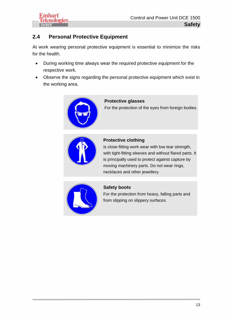
Protective glasses
For the protection of the eyes from foreign bodies.
Protective clothing
is close-fitting work wear with low tear strength,
with tight-fitting sleeves and without flared parts. It
is principally used to protect against capture by
moving machinery parts. Do not wear rings,
necklaces and other jewellery.
Safety boots
For the protection from heavy, falling parts and
from slipping on slippery surfaces.
Control and Power Unit DCE 1500
Safety
14
2.5 Special Risks
The residual risks which arise from the hazard analysis are described in the
following chapter.
Please consider the below mentioned security advices and warnings in the
following chapters of this manual to reduce health hazards and to avoid dangerous
situations.
Electric current
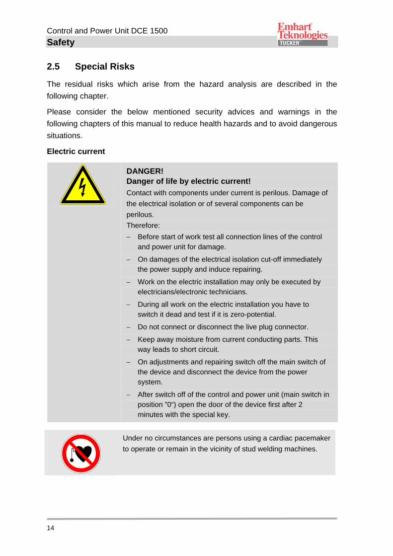
DANGER! Danger of life by electric current!
Contact with components under current is perilous. Damage of
the electrical isolation or of several components can be
perilous.
Therefore:
Before start of work test all connection lines of the control and power unit for damage.
On damages of the electrical isolation cut-off immediately the power supply and induce repairing.
Work on the electric installation may only be executed by electricians/electronic technicians.
During all work on the electric installation you have to switch it dead and test if it is zero-potential.
Do not connect or disconnect the live plug connector.
Keep away moisture from current conducting parts. This way leads to short circuit.
On adjustments and repairing switch off the main switch of the device and disconnect the device from the power system.
After switch off of the control and power unit (main switch in position ”0“) open the door of the device first after 2 minutes with the special key.
Under no circumstances are persons using a cardiac pacemaker
to operate or remain in the vicinity of stud welding machines.

Control and Power Unit DCE 1500
Safety
15
2.6 Safety Devices
The control and Power unit DCE 1500 is designed for the application within an
installation. It can be integrated into the customer internal safety control via the
connector “Safety circuit”.
The connector plug for the safety circuit is included in delivery of the DCE and it
serves to route the 24V power to the respective customer interface and to
integrate the weld unit into a customer safety circuit control (Operator protection,
stop-operation).
Depending on construction of the DCE, manual or automatic operation, the power
socket “Safety circuit” has to be bypassed accordingly by qualified personnel of the
operator or by the Tucker service technician.
Please also see operating manual “Safety module E485A“.
2.6.1 Operator Protection
The DCE could be integrated into the customer specific emergency stop circuit,
single- or dual channel (category 2 or 4), via connection “Safety circuit“ in order to
be able to switch off the SMPS including peripherals in an emergency situation.
If an emergency stop signal is issued, the master contactor in the DCE disconnect
the power section and all connected devices from the power supply. Welding
processes which already started will be stopped.
The control electronics and the control panel will be furthermore supplied with voltage.
After the emergency stop was lift, the operating state delays, after re-start of the
DCE about a holding time of approx. 40 seconds.
2.6.2 Interruption of Operation
Irrespective of the integration of the control & power unit into the customer-specific
emergency-stop circuit, the user can also initiate an interruption of operation of the
DCE, single- or dual channel (category 2 or 4), if the Han 10B connector plug
”Safety circuit” is configured accordingly. As is the case for the operator protection,
feeding and welding of studs will be terminated after the last welding process has
been executed
After cancelling the stop-operation, normal operation will be delayed for ca. 10
seconds.
Control and Power Unit DCE 1500
Safety
16
2.7 Securing Against Resetting
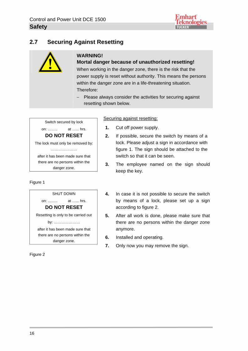
WARNING! Mortal danger because of unauthorized resetting!
When working in the danger zone, there is the risk that the
power supply is reset without authority. This means the persons
within the danger zone are in a life-threatening situation.
Therefore:
Please always consider the activities for securing against resetting shown below.
Switch secured by lock
on: …….. at …... hrs.
DO NOT RESET
The lock must only be removed by:
…………………
after it has been made sure that
there are no persons within the
danger zone.
Securing against resetting:
1. Cut off power supply.
2. If possible, secure the switch by means of a
lock. Please adjust a sign in accordance with
figure 1. The sign should be attached to the
switch so that it can be seen.
3. The employee named on the sign should
keep the key.
Figure 1
SHUT DOWN
on: …….. at …... hrs.
DO NOT RESET
Resetting is only to be carried out
by: …………………
after it has been made sure that
there are no persons within the
danger zone.
4. In case it is not possible to secure the switch
by means of a lock, please set up a sign
according to figure 2.
5. After all work is done, please make sure that
there are no persons within the danger zone
anymore.
6. Installed and operating.
7. Only now you may remove the sign.
Figure 2
Control and Power Unit DCE 1500
Technical Specifications
17
3 Technical Specifications
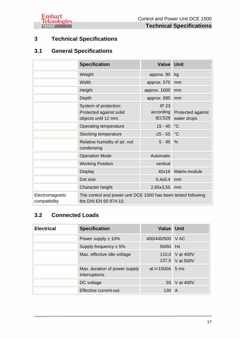
3.1 General Specifications
Specification Value Unit
Weight approx. 90 kg
Width approx. 570 mm
Height approx. 1000 mm
Depth approx. 685 mm
System of protection:
Protected against solid objects until 12 mm.
IP 23 according
IEC529
Protected against water drops
Operating temperature 15 - 40 °C
Stocking temperature -25 - 55 °C
Relative humidity of air, not condensing
5 - 95 %
Operation Mode Automatic
Working Position vertical
Display 40x16 Matrix-module
Dot size 0,4x0,4 mm
Character height 2,65x3,55 mm
Electromagnetic compatibility
The control and power unit DCE 1500 has been tested following the DIN EN 60 974-10.
3.2 Connected Loads
Electrical Specification Value Unit
Power supply ± 10% 400/440/500 V AC
Supply frequency ± 5% 50/60 Hz
Max. effective idle voltage 110,0 137,5
V at 400V
V at 500V
Max. duration of power supply Interruptions
at I=1500A 5 ms
DC voltage 55 V at 400V
Effective current-out 130 A
Control and Power Unit DCE 1500
Technical Specifications
18
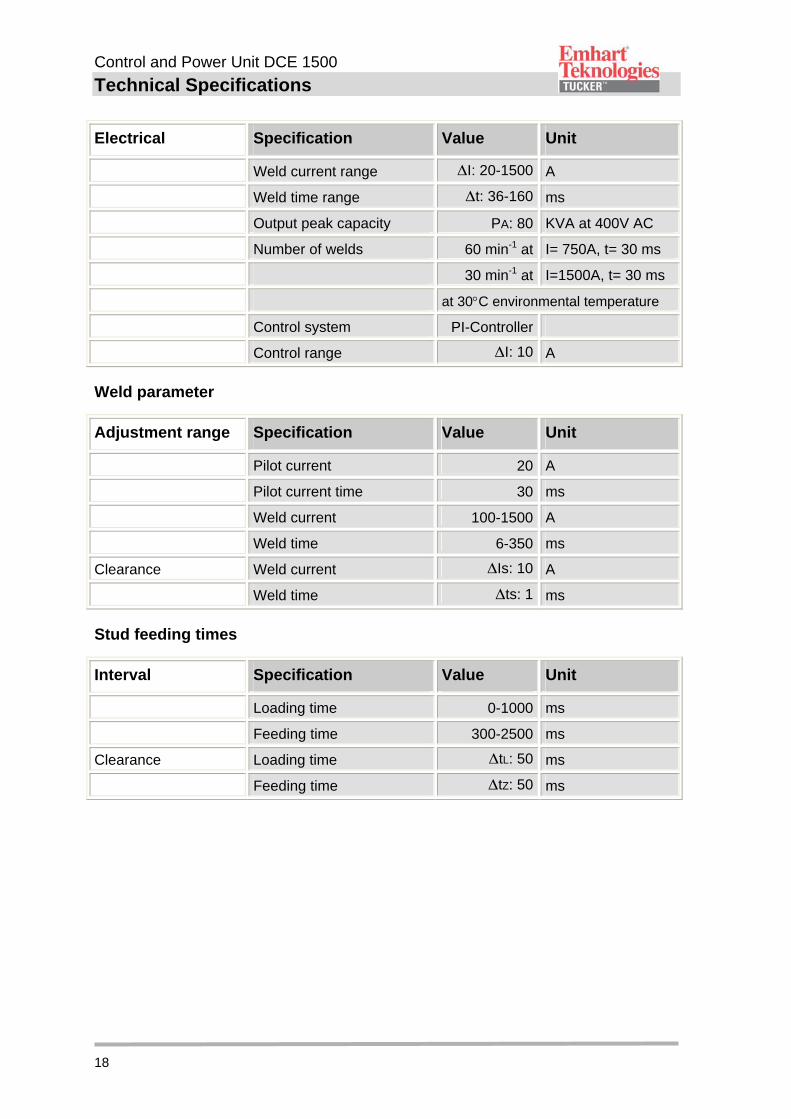
Electrical Specification Value Unit
Weld current range I: 20-1500 A
Weld time range t: 36-160 ms
Output peak capacity PA: 80 KVA at 400V AC
Number of welds 60 min-1 at I= 750A, t= 30 ms
30 min-1 at I=1500A, t= 30 ms
at 30C environmental temperature
Control system PI-Controller
Control range I: 10 A
Weld parameter
Adjustment range Specification Value Unit
Pilot current 20 A
Pilot current time 30 ms
Weld current 100-1500 A
Weld time 6-350 ms
Clearance Weld current Is: 10 A
Weld time ts: 1 ms
Stud feeding times
Interval Specification Value Unit
Loading time 0-1000 ms
Feeding time 300-2500 ms
Clearance Loading time tL: 50 ms
Feeding time tZ: 50 ms
Control and Power Unit DCE 1500
Technical Specifications
19
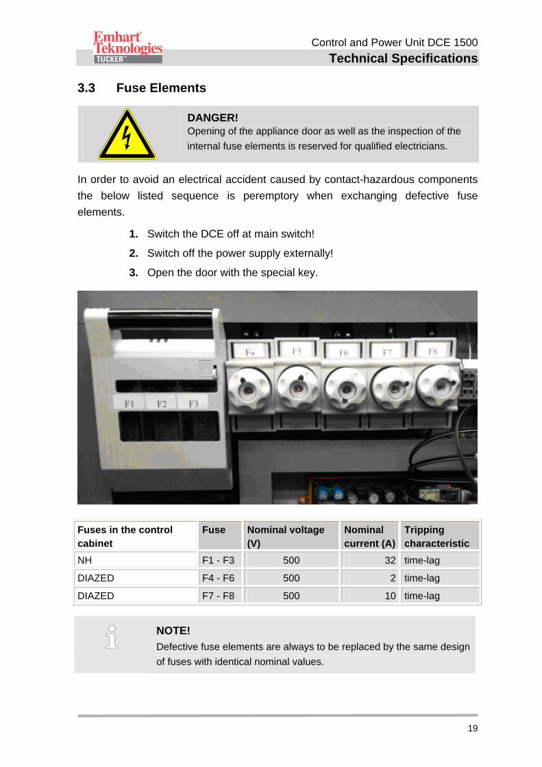
3.3 Fuse Elements
DANGER! Opening of the appliance door as well as the inspection of the
internal fuse elements is reserved for qualified electricians.
In order to avoid an electrical accident caused by contact-hazardous components
the below listed sequence is peremptory when exchanging defective fuse
elements.
1. Switch the DCE off at main switch!
2. Switch off the power supply externally!
3. Open the door with the special key.
Fuses in the control cabinet
Fuse Nominal voltage (V)
Nominal current (A)
Tripping characteristic
NH F1 - F3 500 32 time-lag
DIAZED F4 - F6 500 2 time-lag
DIAZED F7 - F8 500 10 time-lag
NOTE!
Defective fuse elements are always to be replaced by the same design
of fuses with identical nominal values.
Control and Power Unit DCE 1500
Technical Specifications
20
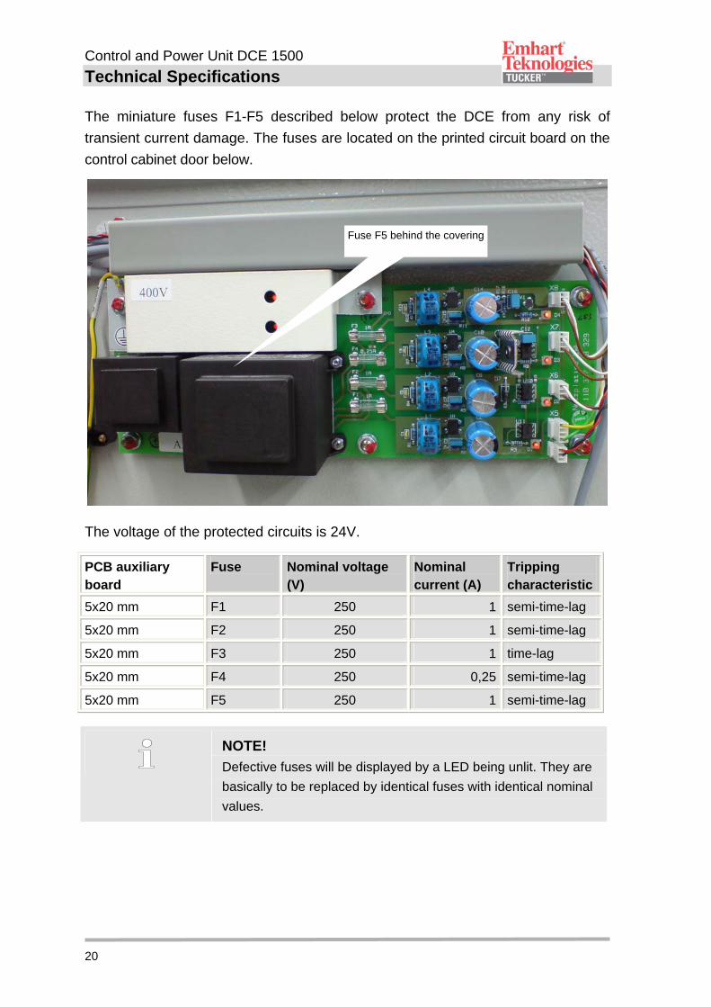
The miniature fuses F1-F5 described below protect the DCE from any risk of
transient current damage. The fuses are located on the printed circuit board on the
control cabinet door below.
The voltage of the protected circuits is 24V.
PCB auxiliary board
Fuse Nominal voltage (V)
Nominal current (A)
Tripping characteristic
5x20 mm F1 250 1 semi-time-lag
5x20 mm F2 250 1 semi-time-lag
5x20 mm F3 250 1 time-lag
5x20 mm F4 250 0,25 semi-time-lag
5x20 mm F5 250 1 semi-time-lag
NOTE!
Defective fuses will be displayed by a LED being unlit. They are
basically to be replaced by identical fuses with identical nominal
values.
Fuse F5 behind the covering
Control and Power Unit DCE 1500
Technical Specifications
21
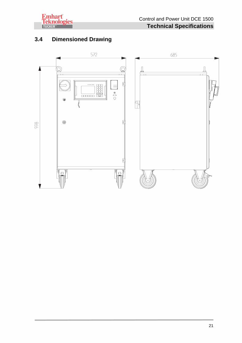
3.4 Dimensioned Drawing
Control and Power Unit DCE 1500
Technical Specifications
22
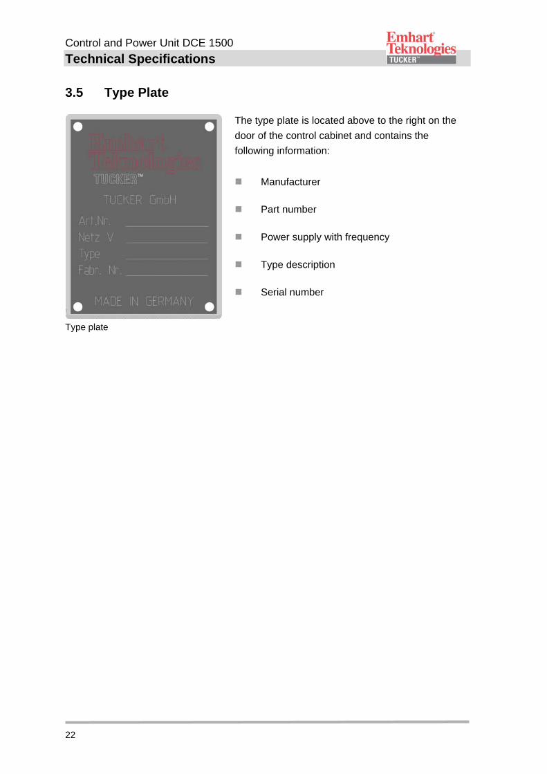
3.5 Type Plate
Type plate
The type plate is located above to the right on the
door of the control cabinet and contains the
following information:
Manufacturer
Part number
Power supply with frequency
Type description
Serial number

Control and Power Unit DCE 1500
General Description
23
4 General Description
The DCE 1500 is an efficient and modern control and power unit, which was
developed by TUCKER for drawn arc stud welding processes. It can be used as a
single or multiple stud weld unit.
Depending on the DCE 1500 model up to five "SFLM“ or “ETF” type stud feeders
can be connected in standard operation, each of which supply a weld head or a
weld gun with studs.
There is also the possibility of operating with a 2-way stud divider SD 2 or a
multiple stud divider SD X as well as using a colour marking unit for marking
defectively welded studs.
The core of the DCE weld unit is a digitally controlled weld current source which
due to its high operating frequency can intervene into the weld current, even in the
case of extremely short weld currents. In addition, the electric arc voltage can be
influenced in a control technique fashion together with the digitally-controlled linear
motor drive of the Tucker welding tools.
Furthermore the DCE 1500 is able to compensate for short-term power supply
interruptions as well as for changes in weld resistance and arc voltage fluctuations
within one millisecond.
The integration of 16 bit multiprocessors as well as digital signal processors and
the utilisation of plastic optical fibres guarantee quick access to the individual
modules and ensure a high degree of data transmission reliability. The entire
software can be directly downloaded from a PC/laptop to DCE by means of a flash
memory.
The data saved in the DCE can be transmitted to a central PC/Laptop via a
standard interface. Networking capability of the control & power unit is provided via
an Ethernet interface.
Communication to the DCE control & power unit with an external controller is
accomplished via a customer interface. There are two options available, one
parallel or one serial interface version.
The DCE 1500 is equipped with a Category 2 safety device. A Category 4 device
is optionally available.
Control and Power Unit DCE 1500
Assembly and Connections
24
5 Assembly and Connections
5.1 Layout DCE 1500
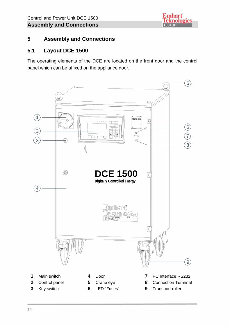
The operating elements of the DCE are located on the front door and the control
panel which can be affixed on the appliance door.
6
7
8
5
9
4
3
2
1
1 Main switch
2 Control panel
3 Key switch
4 Door
5 Crane eye
6 LED “Fuses“
7 PC Interface RS232
8 Connection Terminal
9 Transport roller
DCE 1500Digitally Controlled Energy
Control and Power Unit DCE 1500
Assembly and Connections
25
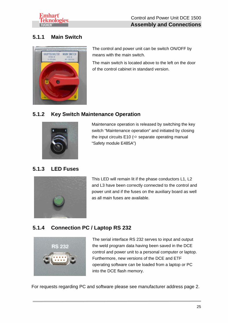
5.1.1 Main Switch
The control and power unit can be switch ON/OFF by
means with the main switch.
The main switch is located above to the left on the door
of the control cabinet in standard version.
5.1.2 Key Switch Maintenance Operation
Maintenance operation is released by switching the key
switch “Maintenance operation“ and initiated by closing
the input circuits E10 ( separate operating manual
“Safety module E485A”)
5.1.3 LED Fuses
This LED will remain lit if the phase conductors L1, L2
and L3 have been correctly connected to the control and
power unit and if the fuses on the auxiliary board as well
as all main fuses are available.
5.1.4 Connection PC / Laptop RS 232
The serial interface RS 232 serves to input and output
the weld program data having been saved in the DCE
control and power unit to a personal computer or laptop.
Furthermore, new versions of the DCE and ETF
operating software can be loaded from a laptop or PC
into the DCE flash memory.
For requests regarding PC and software please see manufacturer address page 2.
Control and Power Unit DCE 1500
Assembly and Connections
26
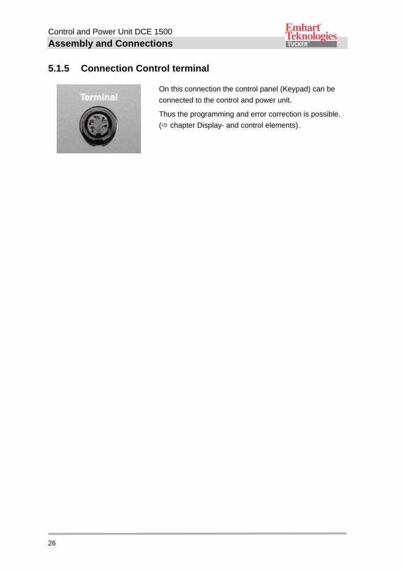
5.1.5 Connection Control terminal
On this connection the control panel (Keypad) can be
connected to the control and power unit.
Thus the programming and error correction is possible.
( chapter Display- and control elements).
Control and Power Unit DCE 1500
Assembly and Connections
27
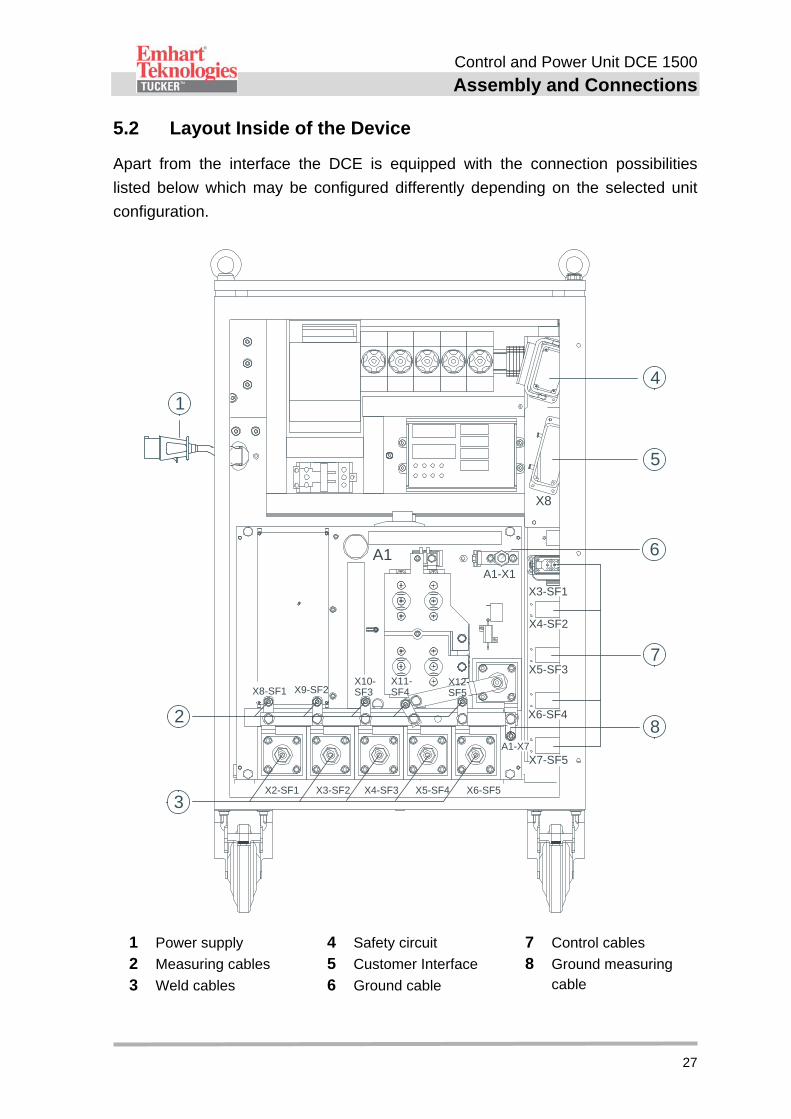
5.2 Layout Inside of the Device
Apart from the interface the DCE is equipped with the connection possibilities
listed below which may be configured differently depending on the selected unit
configuration.
X8
X3-SF1
A1-X1
A1-X7
X4-SF2
X5-SF3
X6-SF4
X7-SF5
X8-SF1 X9-SF2
X2-SF1 X3-SF2 X4-SF3 X5-SF4 X6-SF5
X10-SF3
A1
1
4
5
7
6
8
3
2
X11-SF4
X12-SF5
1 Power supply
2 Measuring cables
3 Weld cables
4 Safety circuit
5 Customer Interface
6 Ground cable
7 Control cables
8 Ground measuring cable
Control and Power Unit DCE 1500
Assembly and Connections
28
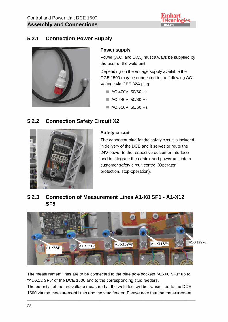
5.2.1 Connection Power Supply
Power supply
Power (A.C. and D.C.) must always be supplied by
the user of the weld unit.
Depending on the voltage supply available the
DCE 1500 may be connected to the following AC.
Voltage via CEE 32A plug:
AC 400V; 50/60 Hz
AC 440V; 50/60 Hz
AC 500V; 50/60 Hz
5.2.2 Connection Safety Circuit X2
Safety circuit
The connector plug for the safety circuit is included
in delivery of the DCE and it serves to route the
24V power to the respective customer interface
and to integrate the control and power unit into a
customer safety circuit control (Operator
protection, stop-operation).
5.2.3 Connection of Measurement Lines A1-X8 SF1 - A1-X12 SF5
The measurement lines are to be connected to the blue pole sockets "A1-X8 SF1“ up to
"A1-X12 SF5“ of the DCE 1500 and to the corresponding stud feeders.
The potential of the arc voltage measured at the weld tool will be transmitted to the DCE
1500 via the measurement lines and the stud feeder. Please note that the measurement
A1-X8SF1 A1-X9SF2 A1-X10SF3 A1-X11SF4 A1-X12SF5
Control and Power Unit DCE 1500
Assembly and Connections
29
lines may not be subject to tension since the pole sockets cannot be locked.
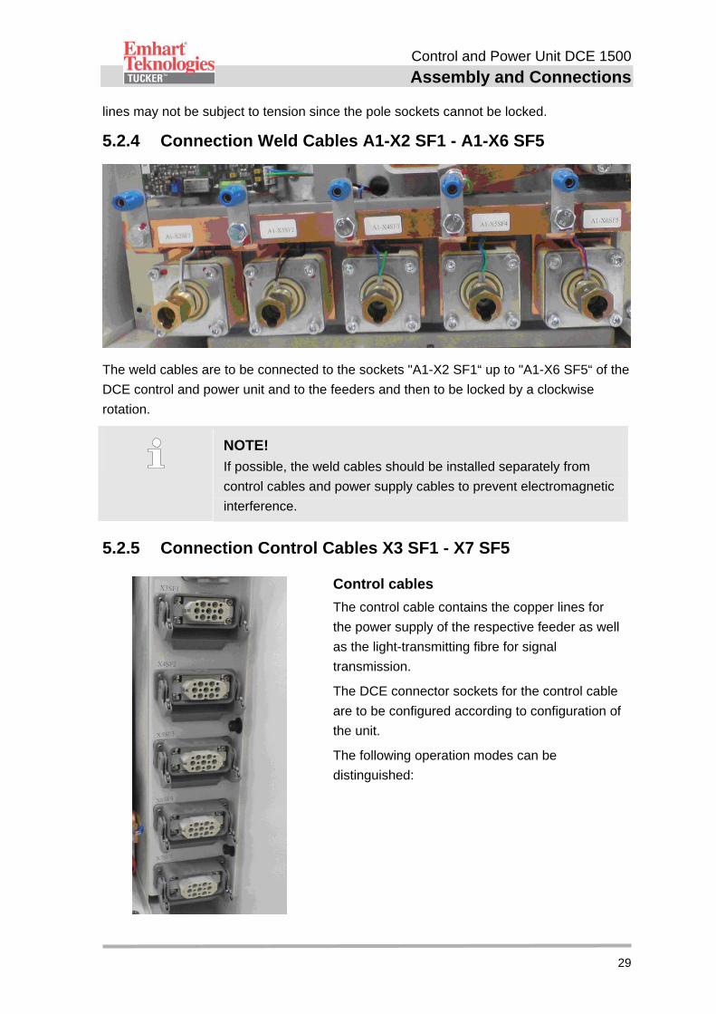
5.2.4 Connection Weld Cables A1-X2 SF1 - A1-X6 SF5
The weld cables are to be connected to the sockets "A1-X2 SF1“ up to "A1-X6 SF5“ of the
DCE control and power unit and to the feeders and then to be locked by a clockwise
rotation.
NOTE!
If possible, the weld cables should be installed separately from
control cables and power supply cables to prevent electromagnetic
interference.
5.2.5 Connection Control Cables X3 SF1 - X7 SF5
Control cables
The control cable contains the copper lines for
the power supply of the respective feeder as well
as the light-transmitting fibre for signal
transmission.
The DCE connector sockets for the control cable
are to be configured according to configuration of
the unit.
The following operation modes can be
distinguished:
Control and Power Unit DCE 1500
Assembly and Connections
30
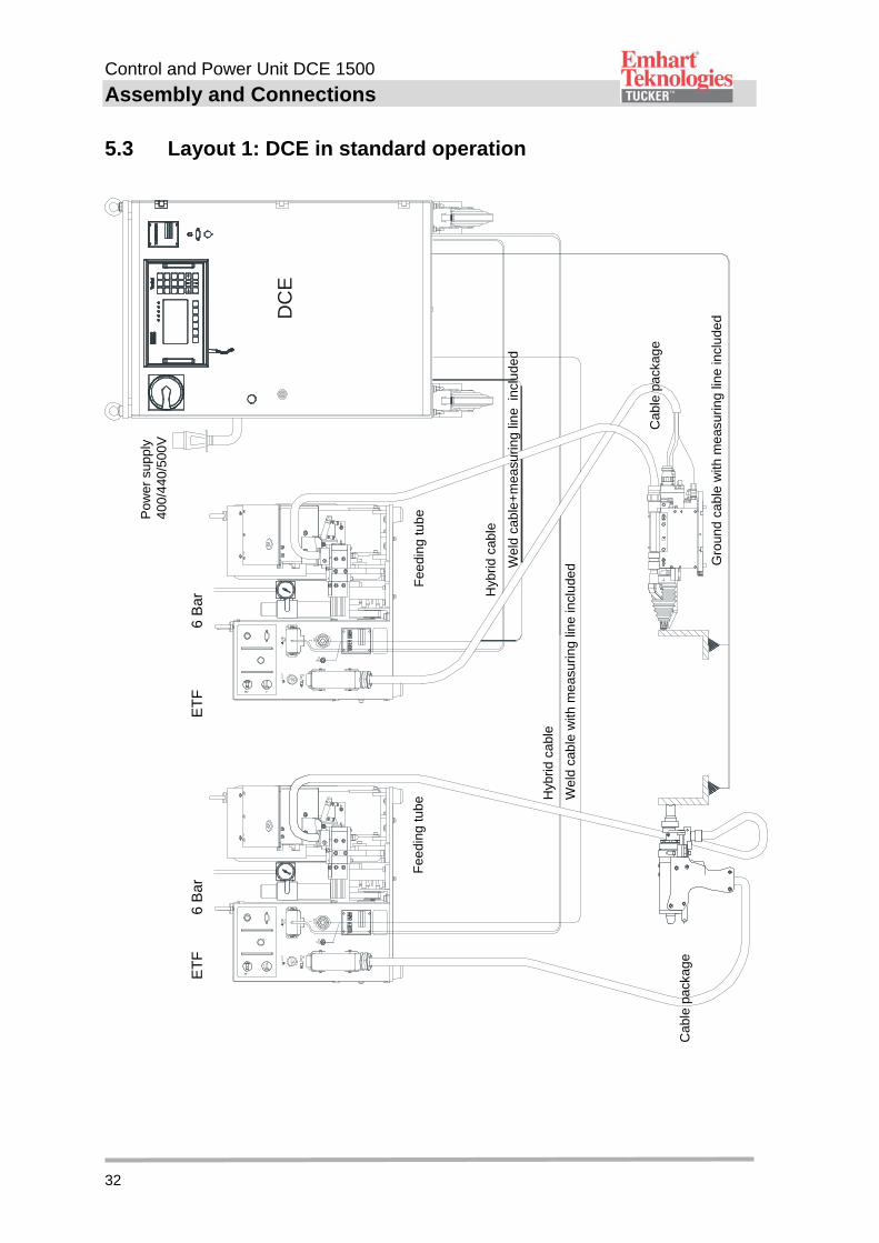
1. Standard Operation with stud feeder and weld tool (LM/SKK/PK/PLM)
Up to five "SF, SFLM or ETF“ type stud feeders each of which supply one weld
head (LM/SKK) or one weld gun (PLM/PK) with studs can be connected to the
connections marked X3 SF1 - X7 SF5 (see connection diagram 1). The ETF
feeder can be equally operated in the same manner as the only conventional and
LM-driven welding tool.
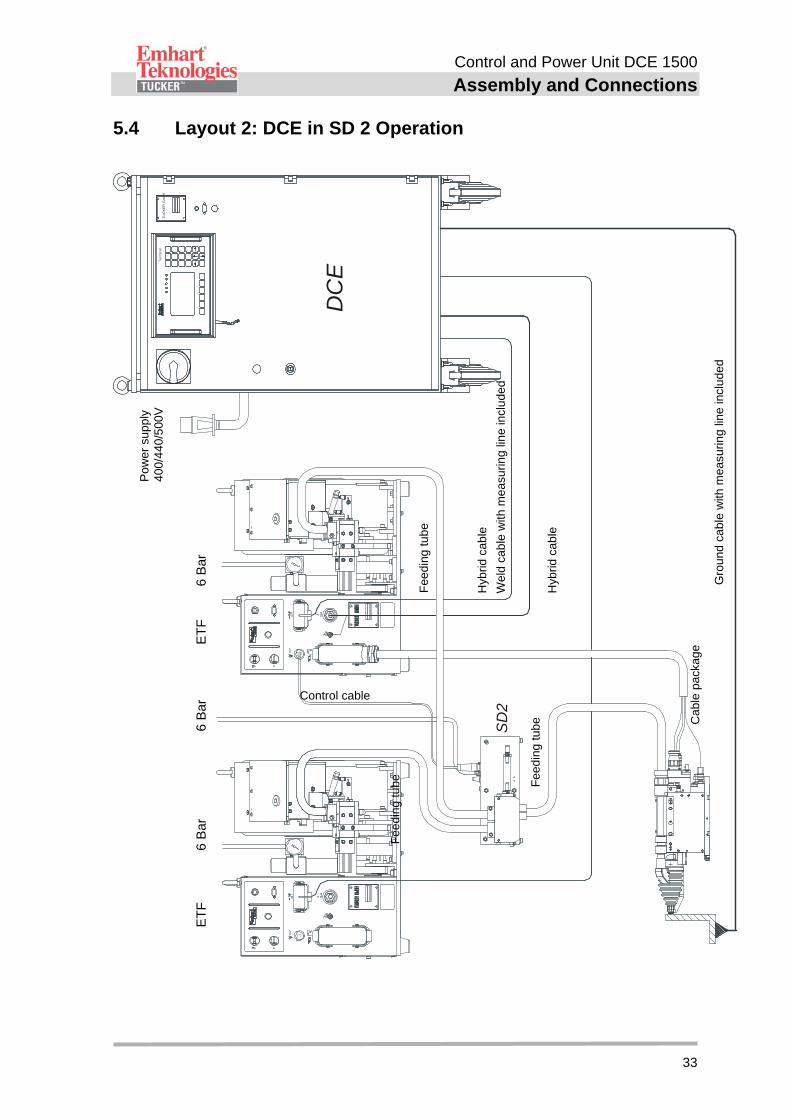
2. Stud Divider Operation with a 2-way stud divider SD2
The stud feeder for controlling the stud divider is to be connected to the socket
X3 SF1 (see layout 2). The stud feeder for feeding the second stud is to be
connected to the socket X4 SF2 located below.
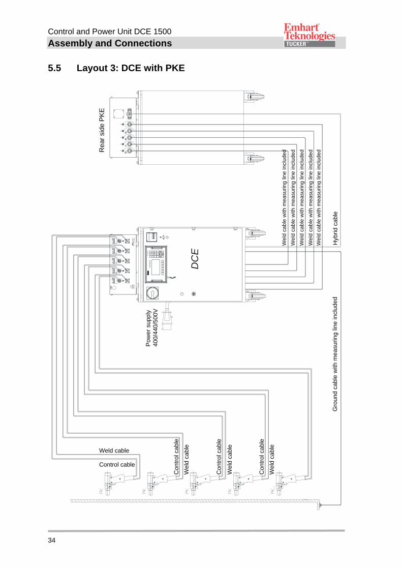
3. Manual Weld Gun Operation
For the operation of up to five weld guns with manual stud feed via the control and
power unit DCE 1500, a PKE connection box is required.
The control cable of the PKE is always to be connected to the DCE socket "X3
SF1“ (see layout 3).
The remaining control cable connections are available for standard applications.
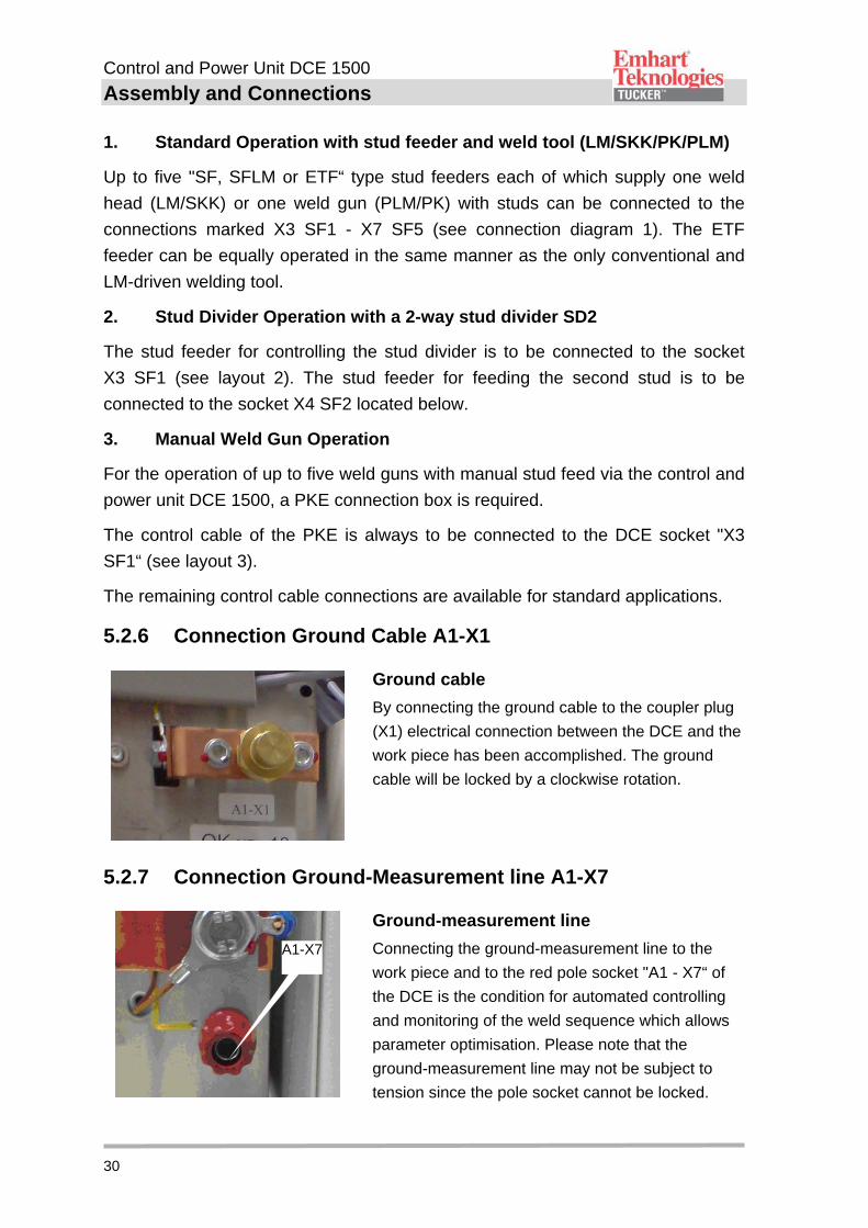
5.2.6 Connection Ground Cable A1-X1
Ground cable
By connecting the ground cable to the coupler plug
(X1) electrical connection between the DCE and the
work piece has been accomplished. The ground
cable will be locked by a clockwise rotation.
5.2.7 Connection Ground-Measurement line A1-X7
Ground-measurement line
Connecting the ground-measurement line to the
work piece and to the red pole socket "A1 - X7“ of
the DCE is the condition for automated controlling
and monitoring of the weld sequence which allows
parameter optimisation. Please note that the
ground-measurement line may not be subject to
tension since the pole socket cannot be locked.
A1-X7
Control and Power Unit DCE 1500
Assembly and Connections
31
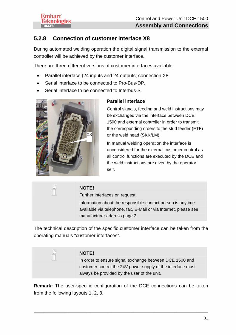
5.2.8 Connection of customer interface X8
During automated welding operation the digital signal transmission to the external
controller will be achieved by the customer interface.
There are three different versions of customer interfaces available:
Parallel interface (24 inputs and 24 outputs; connection X8.
Serial interface to be connected to Pro-Bus-DP.
Serial interface to be connected to Interbus-S.
Parallel interface
Control signals, feeding and weld instructions may
be exchanged via the interface between DCE
1500 and external controller in order to transmit
the corresponding orders to the stud feeder (ETF)
or the weld head (SKK/LM).
In manual welding operation the interface is
unconsidered for the external customer control as
all control functions are executed by the DCE and
the weld instructions are given by the operator
self.
NOTE!
Further interfaces on request.
Information about the responsible contact person is anytime
available via telephone, fax, E-Mail or via Internet, please see
manufacturer address page 2.
The technical description of the specific customer interface can be taken from the
operating manuals “customer interfaces”.
NOTE!
In order to ensure signal exchange between DCE 1500 and
customer control the 24V power supply of the interface must
always be provided by the user of the unit.
Remark: The user-specific configuration of the DCE connections can be taken
from the following layouts 1, 2, 3.
X8
Control and Power Unit DCE 1500
Assembly and Connections
32
5.3 Layout 1: DCE in standard operation
Wel
d ca
ble
+m
easu
ring
lin
e in
clu
ded
Pow
er s
uppl
y 40
0/4
40/5
00V
Cab
le p
acka
ge
Fee
ding
tub
e F
eedi
ng tu
be
Cab
le p
acka
ge
Hyb
rid c
able
Wel
d ca
ble
with
mea
suri
ng li
ne
incl
ude
d
ET
F
6
Bar
E
TF
6 B
ar
DC
E
Gro
und
cabl
e w
ith m
easu
ring
line
incl
ude
d
Hyb
rid c
able
Control and Power Unit DCE 1500
Assembly and Connections
33
5.4 Layout 2: DCE in SD 2 Operation
T
UC
KE
R G
mb
HT
erm
ina
l
DC
E
SD
2
Gro
und
cabl
e w
ith m
easu
ring
line
incl
ude
d
Pow
er s
uppl
y 40
0/4
40/5
00V
Fee
ding
tub
e
Cab
le p
acka
ge
Hyb
rid c
able
Wel
d ca
ble
with
mea
suri
ng li
ne
incl
ude
d
Hyb
rid c
able
ET
F
6 B
ar
6
Bar
ET
F
6
Bar
Fee
ding
tub
e
Fee
ding
tub
e
Control cable
Control and Power Unit DCE 1500
Assembly and Connections
34
5.5 Layout 3: DCE with PKE
TU
CK
ER
Gm
bHT
erm
inal
DC
E
Gro
und
cabl
e w
ith m
easu
ring
line
incl
ude
d
Pow
er s
uppl
y 40
0/4
40/5
00V
Rea
r si
de P
KE
Wel
d ca
ble
with
mea
surin
g lin
e in
clud
ed
Wel
d ca
ble
with
mea
surin
g lin
e in
clud
ed
Wel
d ca
ble
with
mea
surin
g lin
e in
clud
ed
Wel
d ca
ble
with
mea
surin
g lin
e in
clud
ed
Wel
d ca
ble
with
mea
surin
g lin
e in
clud
ed
Hyb
rid c
able
Con
tro
l cab
le
Wel
d ca
ble
Con
tro
l cab
le
Wel
d ca
ble
Con
tro
l cab
le
Wel
d ca
ble
Weld cable Control cable
Control and Power Unit DCE 1500
Display- and Control Elements
35
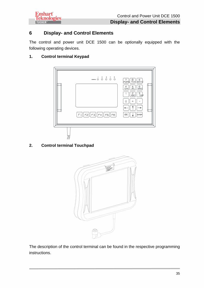
6 Display- and Control Elements
The control and power unit DCE 1500 can be optionally equipped with the
following operating devices.
1. Control terminal Keypad
PQRS
GHI
ABC DEF
TUV WXYZ
JKL MNO
2. Control terminal Touchpad
The description of the control terminal can be found in the respective programming
instructions.
Control and Power Unit DCE 1500
Conversion from Keypad to Touchpad
36
7 Conversion from Keypad to Touchpad
For a later conversion to control terminal Touchpad you need an additional
upgrade kit with all required parts.
Update ZCPU Firmware
To use the control terminal Touchpad the software version on the ZCPU must be
at least version 1.08. If an older version is installed on the CCPU you need to
update the firmware before you can use the control terminal Touchpad.
Note!
The refitting parts needed for the conversion are to be discussed with
and can be ordered by the TUCKER customer service.
Please regard the following points:
Exchange fuse inside the DCE
DANGER! Opening of the appliance door as well as the inspection of the
internal fuse elements is reserved for qualified electricians.
In order to avoid an electrical accident caused by contact-hazardous components
the below listed sequence is peremptory when exchanging defective fuse
elements.
1. Switch the DCE off at main switch!
2. Switch off the power supply externally!
3. Open the door with the special key.
Control and Power Unit DCE 1500
Conversion from Keypad to Touchpad
37
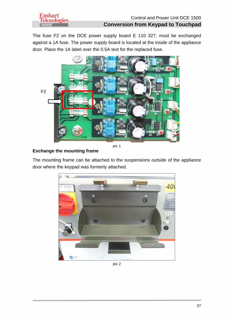
The fuse F2 on the DCE power supply board E 110 327, must be exchanged
against a 1A fuse. The power supply board is located at the inside of the appliance
door. Place the 1A label over the 0.5A text for the replaced fuse.
pic 1
Exchange the mounting frame
The mounting frame can be attached to the suspensions outside of the appliance
door where the keypad was formerly attached.
pic 2
F2
Control and Power Unit DCE 1500
Notes Regarding Stud Welding
38
8 Notes Regarding Stud Welding
NOTE!
Stud welding causes impulsive forces of the power supply voltage.
The connection of external devices to the same power system could
cause malfunctions or disturbances of these devices!
Remark: Due to the welding energy source (SMPS-Technology) inserted in the
DCE 1500, an increased grid-bound HF-interference level is to be faced.
To avoid malfunction of electrically connected devices and to exclude impacts of
the DCE by external installations, regard the Tucker ”Installation guidelines for
DCE welding units“ as well as the following notes:
The power supply of the DCE with AC 400V, 440V or 500V should be always
provided by a parted weld power system.
The operator of the welding installation should keep in mind that there are
preferably no combined supply voltage paths with other welding processes.
If different welding processes are used at one work piece, ensure that these
have no combined welding path of the current and no combined supply
voltage path. Then a parallel welding operation is also possible.
Welding processes with high frequency ignition and plasma welding
processes have to be carried out far away from each other.
Attend to a low-impedance ground connection. On currents of 1500 A the
welding circuit should have a resistance of R 8, 7 m.
NOTE!
An Excel program for calculation of the valid cross-sections and
lengths of the lines can be purchased for free. Please see
manufacturer address page 2.
The ground cable on the work piece has to be installed symmetrically and not
directly beside the welding site, to avoid adverse effects on the welding
quality.
The DCE 1500 has to be connected with a low-impedance protective earth, so
that the leakage currents which occur on welding could flow securely.
Control and Power Unit DCE 1500
DCE 1500 Start-Up
39
9 DCE 1500 Start-Up
NOTE!
The start-up is exclusively reserved for the authorised and
qualified service personnel!
It must be ensured that the DCE 1500 will be placed on a stable and level
surface in order to allow an unhindered opening of unit door.
A minimum distance of 2 m to permanent heat sources must be kept in order
to assure a temperature exchange with the environment.
CAUTION! The operating voltage of the DCE 1500 has to correspond with
the supply voltage of the mains power supply. On disregard
damages of the DCE cannot be eliminated!
Therefore:
Before start-up of the control and power unit compare the data on the type plate with the supply voltage of the customer.
For start-up observe the following sequence:
1. Configure the DCE-specific connectors according to chapter "Connection and Installation".
2. Connect the peripherals taking into consideration the device-specific operating manuals.
3. Switch on the DCE 1500. The type of the unit will be displayed.
4. After the main menu appears in the display switch into the menu “State” and afterwards into the submenu “System” via the cursor keys.
5. Check the configuration of the unit displayed with the connected peripherals.
6. In case the data does not match peripherals must be re-configured.
Control and Power Unit DCE 1500
DCE 1500 Start-Up
40
7. In case data matches you can exit the menu ”Status - System“ by pressing twice the button ”ESC“ and switch into the menu “System configuration” - ”System parameter”.
8. Configure the connected devices of the outputs 1 to 5 according to their requirements.
9. Afterwards switch again into the main menu by repeated pressing of the button ”ESC“ and call up the menu ”Programming“ on.
10. Program the output related parameters in the submenu ”Programming weld outlet“ and the welding parameters in the submenu ”Programming weld program“.
11. Having terminated programming, exit the input mode with ”ENTER” and return to the main menu by pressing the button”F2”.
12. Now several test welds should be performe d in order to verify accuracy of the programmed parameters.
NOTE!
Start up of the DCE is only possible after exact pin assignment of the
plug ”Safety circuit“. The pin configuration can be taken from the
operating manual “Safety Module E485A“.
NOTE!
A programming manual for DCE/ETF is available and can be
requested anytime via our after sales service. Please see
manufacturer address page 2.
Control and Power Unit DCE 1500
Transport, Packaging and Storing
41
10 Transport, Packaging and Storing
NOTE!
The installation and initial operation is effected exclusively by
personnel or by authorized persons of the manufacturer.
However, it may happen that in line with the installation and the
further use operators or maintenance personnel of the operating
company are consigned with the handling of packages.
In this case regard the following notes.
10.1 Security Advice for the Transport
WARNING! Danger to life due to floating loads!
On lifting of loads there is a danger to life due to falling or
uncontrolled swivelling parts.
Therefore:
Never step under floating loads.
Regard the specifications to the intended attachment points.
Do not attach something to overhanging machine parts or to ears of attached components. Pay attention to a tight fit of the load-securing devices.
Only use licensed lifting tools and load-securing devices with sufficient load capacity.
Do not use slightly ripped or abrased ropes and belts.
Do not attach ropes and belts to sharp-edged flanges and edges, do not knot and do not twist.
Control and Power Unit DCE 1500
Transport, Packaging and Storing
42
10.2 Transport Check
Upon delivery, the equipment, including accessories, should be checked for
completeness and damage. On externally visible transport damage, proceed as
follows:
Do not accept the delivery or only accept with reservation.
Note the extent of damage on the transport documents or on the delivery
note of the deliverer.
Induce complaint.
NOTE!
Complain each defect as soon as recognized. Claims for damages
can only be asserted within the effective time for complaints.
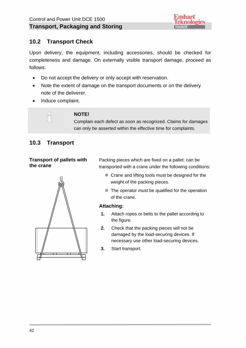
10.3 Transport
Transport of pallets with the crane
Packing pieces which are fixed on a pallet, can be
transported with a crane under the following conditions:
Crane and lifting tools must be designed for the
weight of the packing pieces.
The operator must be qualified for the operation
of the crane.
Attaching:
1. Attach ropes or belts to the pallet according to the figure.
2. Check that the packing pieces will not be damaged by the load-securing devices. If necessary use other load-securing devices.
3. Start transport.
Control and Power Unit DCE 1500
Transport, Packaging and Storing
43
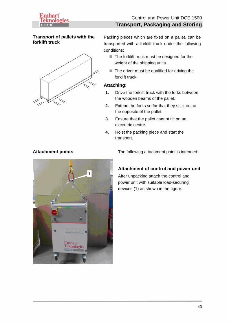
Transport of pallets with the forklift truck
Packing pieces which are fixed on a pallet, can be
transported with a forklift truck under the following
conditions:
The forklift truck must be designed for the
weight of the shipping units.
The driver must be qualified for driving the
forklift truck.
Attaching:
1. Drive the forklift truck with the forks between the wooden beams of the pallet.
2. Extend the forks so far that they stick out at the opposite of the pallet.
3. Ensure that the pallet cannot tilt on an excentric centre.
4. Hoist the packing piece and start the transport.
Attachment points The following attachment point is intended:
Attachment of control and power unit
After unpacking attach the control and
power unit with suitable load-securing
devices (1) as shown in the figure.
1
Control and Power Unit DCE 1500
Transport, Packaging and Storing
44
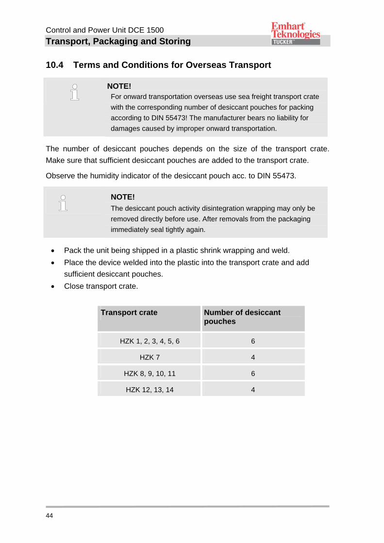
10.4 Terms and Conditions for Overseas Transport
NOTE! For onward transportation overseas use sea freight transport crate
with the corresponding number of desiccant pouches for packing
according to DIN 55473! The manufacturer bears no liability for
damages caused by improper onward transportation.
The number of desiccant pouches depends on the size of the transport crate.
Make sure that sufficient desiccant pouches are added to the transport crate.
Observe the humidity indicator of the desiccant pouch acc. to DIN 55473.
NOTE!
The desiccant pouch activity disintegration wrapping may only be
removed directly before use. After removals from the packaging
immediately seal tightly again.
Pack the unit being shipped in a plastic shrink wrapping and weld.
Place the device welded into the plastic into the transport crate and add
sufficient desiccant pouches.
Close transport crate.
Transport crate Number of desiccant pouches
HZK 1, 2, 3, 4, 5, 6 6
HZK 7 4
HZK 8, 9, 10, 11 6
HZK 12, 13, 14 4
Control and Power Unit DCE 1500
Transport, Packaging and Storing
45
10.5 Packaging
The respective packaging pieces are packed according to the transport conditions
to expect. Exclusively non-polluting materials were used for packaging.
The packaging shall protect the respective components against transport
damages, corrosion and other damages until assembly. Therefore do not destroy
the packaging and remove just shortly before assembly.
Packaging materials
handling
Dispose packaging material according to the respectively valid
legal regulations and local directives.
CAUTION! Damage caused to the environment due to wrong disposal!
Packaging materials are valuable raw materials and can be
further used in a lot of cases or can be prepared reasonably and
recycled. Therefore:
Dispose packaging materials environmentally friendly.
Regard the locally effective regulations for waste disposal. Charge a specialist with the disposal if applicable.
10.6 Storing
Storing of the packaging pieces
Store the packaging pieces under the following conditions:
Do not store out of doors.
Store dry and dust-free.
Protect against insolation.
Avoid mechanical vibrations.
Stocking temperature: -25 to +55 °C.
Relative humidity of air (not condensing): 5 to 95 %.
On storage longer than 3 months the general condition of
all parts and the packaging has to be checked regularly.
Refresh or exchange the conservation if necessary.
NOTE!
Notes regarding storage which exceed the requirements mentioned
here are possibly on the packaging pieces. These are to be
observed respectively.
Control and Power Unit DCE 1500
Maintenance and Cleaning
46
11 Maintenance and Cleaning
11.1 Safety
Personnel The maintenance work described can be executed by the
operator, unless it is marked differently.
Some maintenance work may only be executed by specially
trained experts.
Maintenance work on the electric installation basically may only
be executed by specialists for electronics.
Improper execution of maintenance work
WARNING! Risk of injury due to improper executed maintenance work!
Improper maintenance can lead to heavy damage to persons and
property.Therefore:
Before start of work arrange for a sufficient space for assembly.
If components have been removed pay attention to a correct assembly, install all fastening elements again and observe screw tightening torques.
11.2 Maintenance and Cleaning Schedule
The maintenance work essential for an optimal and failure-free operation is
described in the following chapters.
In case of detection of an increased abrasion during regular checks, shorten the
required maintenance intervals accordingly to the actual signs of abrasion.
If you have questions concerning maintenance work and intervals contact the
manufacturer, see service address on page 2.
Control and Power Unit DCE 1500
Maintenance and Cleaning
47
Interval Wearing work To be carried out by
daily Check connection cables, connection plugs and connector assembly for mechanical damage and loose contacts
Operator
semi-annually Check filter insert for contamination Qualified personnel
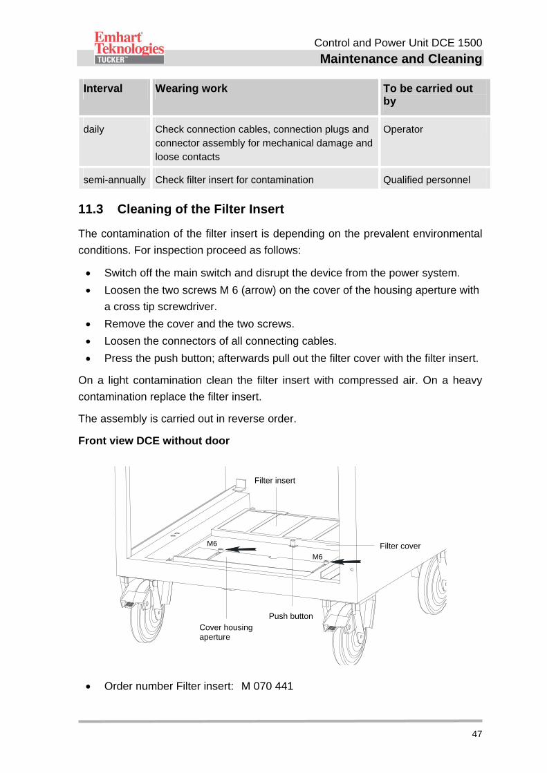
11.3 Cleaning of the Filter Insert
The contamination of the filter insert is depending on the prevalent environmental
conditions. For inspection proceed as follows:
Switch off the main switch and disrupt the device from the power system.
Loosen the two screws M 6 (arrow) on the cover of the housing aperture with
a cross tip screwdriver.
Remove the cover and the two screws.
Loosen the connectors of all connecting cables.
Press the push button; afterwards pull out the filter cover with the filter insert.
On a light contamination clean the filter insert with compressed air. On a heavy
contamination replace the filter insert.
The assembly is carried out in reverse order.
Front view DCE without door
Order number Filter insert: M 070 441
Filter cover
Filter insert
Cover housingaperture
Push button
M6
M6
Control and Power Unit DCE 1500
Disposal
48
12 Disposal
Unless no recovery- or disposal arrangement was made disassembled parts have
to be recycled:
Scrap metals.
Recycle plastic elements.
Dispose sorted all the rest of the components according
material properties.
! CAUTION! Damage caused to the environment due to wrong disposal!
Electronic waste, electronic components, lubricants and other
additives are subject to treatment of hazardous waste and may
be disposed only by licensed certified specialists!
The local authority or special disposal specialists provide information regarding an
environmentally friendly disposal.
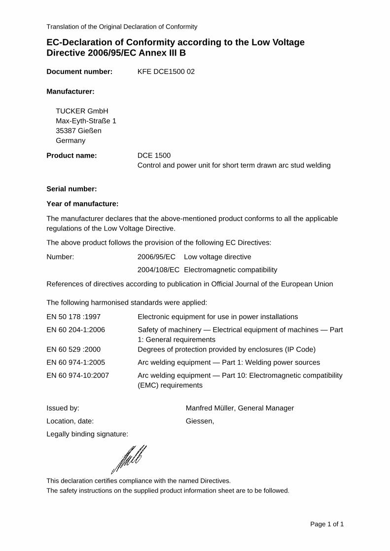
Translation of the Original Declaration of Conformity
Page 1 of 1
EC-Declaration of Conformity according to the Low Voltage Directive 2006/95/EC Annex III B
Document number: KFE DCE1500 02
Manufacturer:
TUCKER GmbH Max-Eyth-Straße 1 35387 Gießen Germany
Product name: DCE 1500 Control and power unit for short term drawn arc stud welding
Serial number:
Year of manufacture:
The manufacturer declares that the above-mentioned product conforms to all the applicable regulations of the Low Voltage Directive.
The above product follows the provision of the following EC Directives:
2006/95/EC Low voltage directive Number:
2004/108/EC Electromagnetic compatibility
References of directives according to publication in Official Journal of the European Union
The following harmonised standards were applied:
EN 50 178 :1997 Electronic equipment for use in power installations
EN 60 204-1:2006 Safety of machinery — Electrical equipment of machines — Part 1: General requirements
EN 60 529 :2000 Degrees of protection provided by enclosures (IP Code)
EN 60 974-1:2005 Arc welding equipment — Part 1: Welding power sources
EN 60 974-10:2007 Arc welding equipment — Part 10: Electromagnetic compatibility (EMC) requirements
Issued by: Manfred Müller, General Manager
Location, date: Giessen,
Legally binding signature:
This declaration certifies compliance with the named Directives.
The safety instructions on the supplied product information sheet are to be followed.


Notizen/Notes: