Embed Size (px)
Citation preview

Digital Pressure and VacuumGauges and Controllers
The Fastest Flow Controller Company in the World!
Operating Manual
P-Series
PCR-Series
PC3-Series
PCD-Series
PC-Series

05/23/2017 Rev33 DOC-PPC16MAN
RECALIBRATIONYour Alicat instrument is a precision device and Alicat strongly recommends that you send it to us on a yearly basis for recalibration.
A yearly recalibration does a few things:
It insures that your unit is functioning according to specification.
Contamination may cause the instrument to measure improperly. Recalibration insures the instrument is clean and free from debris.
Recalibration maintains your LIFETIME WARRANTY!
Sending your unit for recalibration is easy and inexpensive. Recalibrations are usually shipped within five days of receipt, so it’s fast too.
Please keep the original box to return your Alicat instrument for recalibration.
For more information regarding recalibration see page 43.
ACCESSORIESNow that you have your Alicat instrument are you sure you’ve got everything you need? Alicat accessories can make your job easier.
Many of our customers also order:
Power Supplies — A universal wall power supply that makes it easy to power your Alicat unit just about anywhere in the world.
BB9 — Alicat’s multi-drop box that allows easy connection of up to nine Alicat instruments to a single USB, RS-232 or RS-485 port.
MD8DB9 — An RS-232 to 8 pin Mini-DIN cable to connect your Alicat instrument to a computer. A variety of other cables are also available.
Flow Vision™ SC — A GUI based Windows®program that allows easy computer access and control for one or multiple Alicat instruments.
Fittings and filters — Keep your instrument properly connected to your process and free from harmful contamination.
See pages 47-50 for a complete description and list of Alicat accessories.
FULL TECHNICAL SUPPORT | LIFETIME WARRANTY

3
Thank you for purchasing a P-Series Pressure Gauge or PC-Series Vacuum and Pressure Controller. Please take the time to find and read the information for your specific device. This manual covers the following Alicat Scientific instruments:
P-Series Digital Pressure Gauge
PC-Series Vacuum and Pressure Controllers
PCR-Series High Flow Vacuum and Pressure Controllers
PCD and PCRD-Series Dual Valve Pressure Controllers
PS, PCS, PCRS, PCDS and PCRDS-Series — instruments for use with aggressive gases (see pages 64 - 68).
PC3, PCD3, PCR3 and PCRD3-Series Vacuum and Pressure Controllers — pressure controllers fitted with an external pressure port for sensing and controlling pressures at a remote point in the system (see page 34).
PC-EXTSEN Pressure Controllers — instruments for use with an end-user supplied external sensor (see pages 75-77).
This includes P, PC and PCR-Series devices labeled as approved for CSA Class 1 Div 2 and ATEX Class 1 Zone 2 hazardous environments. See pages 78 and 79 for Special Conditions regarding the use of CSA/ATEX labeled devices.
The installation (plumbing, mounting and power/signal connection instructions are applicable to all P, PC (includes PC3), PCR (includes PCR3) and PCD-Series devices.
Unless specifically noted, all instructions for PC-Series Controllers are applicable to PC3, PCR, PCR3, PCD, PCD3, PCRD and PCRD3 controllers as well.
Alicat Portable Pressure Gauges
Note: Alicat Portable Pressure Gauges operate in accordance with the P-Series Pressure Gauge instructions found in this manual. Please see page 44 for information regarding use and recharge.
Please contact Alicat at 1-888-290-6060 or [email protected] if you have any questions regarding the use or operation of this device.Many Alicat instruments are built for specific applications. Two instruments with the same flow range and part number may look and act quite differently depending upon the application the instrument was built for. Care should be taken when moving an instrument from one application to another.
You can find a number of instructional videos related to the operation of this device by visiting the Alicat web site or scanning the QR code.
http://www.alicat.com/support/instructional-videos/
4
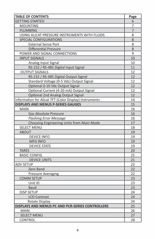
TABLE OF CONTENTS PageGETTING STARTED 6 MOUNTING 7 PLUMBING 7 USING ALICAT PRESSURE INSTRUMENTS WITH FLUIDS 8 SPECIAL CONFIGURATIONS 8 External Sense Port 8 Differential Pressure 8 POWER AND SIGNAL CONNECTIONS 9 INPUT SIGNALS 10 Analog Input Signal 10 RS-232 / RS-485 Digital Input Signal 11 OUTPUT SIGNALS 12 RS-232 / RS-485 Digital Output Signal 12 Standard Voltage (0-5 Vdc) Output Signal 12 Optional 0-10 Vdc Output Signal 12 Optional Current (4-20 mA) Output Signal 12 Optional 2nd Analog Output Signal 12Information for Alicat TFT (Color Display) Instruments 14DISPLAYS AND MENUS P-SERIES GAUGES 15 MAIN 16 Gas Absolute Pressure 16 Flashing Error Message 16 Choosing Engineering Units from Main Mode 17 SELECT MENU 18 ABOUT 19 DEVICE INFO 19 MFG INFO 19 DEVICE STATE 19 TARES 20 BASIC CONFIG 21 DEVICE UNITS 21ADV SETUP 22 Zero Band 22 Pressure Averaging 22 COMM SETUP 23 Unit ID 23 Baud 23 DISP SETUP 24 LCD Contrast 24 Rotate Display 24DISPLAYS AND MENUS PC AND PCR-SERIES CONTROLLERS 25 MAIN 26 SELECT MENU 27 CONTROL 28

5
TABLE OF CONTENTS Page Setpoint Source 28 Loop Variable 29 PID Tuning 30 TARES 32PRESSURE CONTROL APPLICATION: UPSTREAM VALVE 33BACK PRESSURE CONTROL APPLICATION: DOWNSTREAM VALVE 33PC3-Series PRESSURE CONTROLLERS 34DIFFERENTIAL PRESSURE GAUGES 35DIFFERENTIAL PRESSURE CONTROLLERS 36PCD and PCRD DUAL VALVE CONTROLLER OPERATION 37RS-232 OR RS-485 OUTPUT AND INPUT 38 Sending a Command 38 Polling Mode 39 Streaming Mode 39 Data Format 39 Sending a Setpoint via RS-232 / RS-485 40 Additional Serial Commands 40Supported Units List 41TROUBLESHOOTING 42MAINTENANCE AND RECALIBRATION 43Option: Portable Meters and Gauges 44 Pressure Menu for Portable Meters 45Options: Remote Electronics and Remote Panel Display 46Accessory: BB9 Multi-Drop Box 47Accessories: Flow Vision™ SC and Flow Vision™ MX 48Accessories 49P Gauge Technical Specifications 51PC, PC3 PCR and PCR3 Controller Technical Specifications 53PCD, PCD3, PCRD and PCRD3 Controller Technical Specifications 57Technical Data for Aggressive Gas Pressure and Vacuum Devices 61PS Gauge Technical Specifications 62PCS and PCRS Technical Specifications 64PCDS and PCRDS Technical Specifications 66PROFIBUS Technical Specifications 69Eight Pin Mini-DIN Pin-Out 70Locking Industrial Connector Pin-Out 719 pin D-Sub Common Pinouts 7215 pin D-Sub Common Pinouts 73High Density 15 pin D-Sub Common Pinouts 74NOTES FOR USING PC-EXTSEN CONTROLLERS 75Information for CSA and ATEX Labeled Devices 78

6
GETTING STARTED8 Pin Mini-DIN
Display ScreenInlet Connection Port
Outlet Connection Port shown with Plug
Power Jack
P-Series Pressure Gauge
Control Valve
Inlet Connection Port
Flow Direction Arrow
Outlet Connection Port
PRESSPSIA
PC-Series Pressure Controller Shown with Standard Upstream Valve
Inlet Connection Port Outlet Connection Port
PCR-Series Pressure Controller
Control Valve

7
MOUNTINGAll P-Series Gauges and PC-Series Controllers have mounting holes for convenient mounting to flat panels. These gauges are position insensitive and can be mounted in any orientation. The sizes and dimensions for the mounting holes are shown on pages 51 to 68.P-Series Pressure Gauges may be connected into your system with the flow going in either direction for ease of viewing the display. These units are shipped with a plug for dead end applications. This plug should be removed for flow through applications.PC-Series Vacuum and Pressure Controllers are normally intended to control the process pressure downstream of the controller. In order for this to occur the controller should be mounted so the flow goes from left to right as you look at the front of the unit. This puts the measuring portion of the device between the valve and the leakage point where you are attempting to control the pressure application. Back-pressure controllers reverse this configuration (see page 33).
PLUMBINGYour instrument is shipped with plastic plugs fitted in the port openings. To lessen the chance of contaminating the flow stream do not remove these plugs until you are ready to install the device.Make sure that flow is in the direction indicated by the flow arrow.
Standard P-Series Gauges and PC-Series Controllers have female inlet and outlet port connections. Welded VCR and other specialty fittings may have male ports.The inlet and outlet port sizes (process connections) for different flow ranges are shown on pages 51-68.Instruments with M5 (10-32) ports have O-ring face seals and require no sealant or tape. Do not use tape with welded or O-ring fittings.For non M5 (10-32) ports use thread sealing Teflon® tape to prevent leakage around the port threads. Do not wrap the first two threads. This will minimize the possibility of getting tape into the flow stream and flow body.
Do not use pipe dopes or sealants on the process connections as these compounds can cause permanent damage to the controller should they get into the flow stream.
When changing fittings, carefully clean any tape or debris from the port threads.
For additional notes on PCD (dual valve controller) plumbing see page 35.For gas applications, it is recommended that a 40 micron filter be installed upstream of P and PCR-Series instruments and a 20 micron filter be installed upstream of PC and PCD-Series instruments. For liquid applications, see “Using Alicat Pressure Instruments with Fluids”, page 8.
Connecting Fittings and Filters http://www.alicat.com/support/instructional-videos/

8
USING ALICAT PRESSURE INSTRUMENTS WITH FLUIDS
All of these devices may by used with chemically compatible liquids providing a couple of things are taken into account:
1. Water is about 50 times more viscous than air. This is important when sizing a pressure controller. The PC-Series which can be used to flow up to 20 SLPM of gas, will be limited to roughly 0.5 LPM of water-like fluid. The PCR will be limited to roughly 12 LPM of water-like fluid.
2. The factory PID tune is established using air flow. It may be necessary to adjust the PID tuning parameters if you will be using a controller with liquids.
SPECIAL CONFIGURATIONS
P, PC, and PCR-Series pressure devices are occasionally ordered with special configurations which are covered here:
1. External Sense Port: Occasionally it is necessary or desirable to sense the pressure at some point other than at the location of the pressure device. All P, PC, or PCR-Series pressure devices can be ordered with an additional NPT port which is connected directly with the pressure sensor of the device. In these devices the flow path through the device is NOT connected to the pressure sensor. See “PC3-Series Pressure Controllers” – page 34.
2. Differential Pressure: Occasionally it is necessary or desirable to monitor or control a differential pressure. P, PC, and PCR-Series pressure devices can be ordered as low differential pressure devices (usually 1 to 5 psid). These devices have two ports located on the front face of the unit for connection to the points in the system where the differential pressure is to be measured. The upstream port is for the higher pressure and the downstream port is for the lower pressure. In these devices the flow path through the device is NOT connected to either leg of the differential pressure sensor. See “Differential Pressure Gauges and Differential Pressure Controllers” – pages 35 & 36.
PC-EXTSEN units connect a Pressure Controller (with no internal pressure sensor) to an end-user supplied external pressure sensor. Designed mainly for the vacuum coating industry, the PC-EXTSEN marries the sensing ability of an existing capacitance manometer or ion gauge with a 16-Series electronics package and internal PID algorithm. This enables fast and precise control of extreme vacuum conditions in the coating chamber. See pages 75-77.
CAUTION! Exceeding the maximum specified line pressure may cause permanent damage to the solid-state differential pressure transducer.

9
POWER AND SIGNAL CONNECTIONSPower can be supplied to your gauge/controller through either the power jack (power jack not available on CSA/ATEX approved devices) or the 8 pin Mini-DIN connector. An AC to DC adapter which converts line AC power to DC voltage and current as specified below is required to use the power jack. A 2.1mm, positive center, 7-30 Vdc AC/DC adapter rated for at least 100 mA is required to use the adapter jack in a P-Series meter.A 2.1mm, positive center, 12-30 Vdc AC/DC adapter rated for at least 250 mA is required to use the adapter jack in a PC-Series controller. A 2.1mm, positive center, 24-30 Vdc AC/DC adapter rated for at least 500 mA is required to use the adapter jack in a PCR-Series controller.NOTE: 4-20mA analog output requires at least 15 Vdc.
CAUTION! Do not connect power to pins 1 through 6 as permanent damage can occur!
It is common to mistake Pin 2 (labeled 5.12 Vdc Output) as the standard 0-5 Vdc analog output signal. In fact Pin 2 is normally a constant 5.12 Vdc that reflects the system bus voltage and can be used as a source for the set-point signal.For 6 Pin Locking Connector, DB9 and DB15 Pin-outs see pages 71 to 74. For PROFIBUS Pin-outs see page 69.
Standard 8 Pin Mini-DIN Pin-Out
1 2
3 4 5
6 7 8
Pin Function Mini-DIN cable color
1 Not Connected (or optional 4-20mA Primary Output Signal) Black
2 Static 5.12 Vdc [or optional Secondary Analog Output (4-20mA, 5Vdc, 10Vdc) or Basic Alarm] Brown
3 Serial RS-232RX / RS-485(–) Input Signal (receive) Red
4 Meters/Gauges = Remote Tare (Ground to Tare)Controllers = Analog Set-Point Input Orange
5 Serial RS-232TX / RS-485(+) Output Signal (send) Yellow6 0-5 Vdc (or optional 0-10 Vdc) Output Signal Green7 Power In (as described above) Blue8 Ground (common for power, communications and analog signals) Purple
Note: The above pin-out is applicable to all pressure gauges and controllers with the Mini-DIN connector. The availability of different output signals depends on the options ordered. Optional configurations are noted on the unit’s calibration sheet.
Electrical Connections and Basic Wiringhttp://www.alicat.com/support/instructional-videos/

10
INPUT SIGNALSAnalog Input Signal (applicable to controllers only)Apply analog input to Pin 4 as shown on page 9.For 6 Pin Locking Connector, DB9 and DB15 Pin-outs see pages 71 to 74. For PROFIBUS Pin-outs see page 69.Standard 0-5 Vdc is the standard analog input signal. Apply the 0-5 Vdc input signal to pin 4, with common ground on pin 8. Optional 0-10 Vdc: If specified at time of order, a 0-10 Vdc input signal can be applied to pin 4, with common ground on pin 8.Optional 4-20 mA: If specified at time of order, a 4-20 mA input signal can be applied to pin 4, with common ground on pin 8. NOTE: This is a current sinking device. The receiving circuit is essentially a 250 ohm resistor to ground. NOTE: 4-20mA output requires at least 15 Vdc power input.
CAUTION! Do not connect this device to “loop powered’” systems, as this will destroy portions of the circuitry and void the warranty. If you must interface with existing loop powered systems, always use a signal isolator and a separate power supply.
Gauges: A remote tare can be achieved by momentarily grounding pin 4 to tare.
Controllers: A simple method for providing set-point to controllers
4
8
5.12 Vdc
50 KOhm Potentiometer
0-5 Vdc
12
345
678

11
RS-232 / RS-485 Digital Input Signal
To use the RS-232 or RS-485 input signal, connect the RS-232 / RS-485 Output Signal (Pin 5), the RS-232 / RS-485 Input Signal (Pin 3), and Ground (Pin 8) to your computer serial port as shown below. (See page 38 for details on accessing RS-232 / RS-485 input.)
9 8 7 6
9876
15 3 24 1 532 4
Serial Cable End PC Serial Port
1
8 7 6
5
4
3
2
8 Pin MiniDIN Cable End 8 Pin MiniDIN Connector
9 Pin Serial Connection 8 Pin MiniDIN ConnectionPin Function Function Pin5 Ground Ground 83 Transmit Receive 32 Receive Transmit 5
DB9 to Mini-DIN Connection for RS-232 / RS-485 SignalsCommunication Set Uphttp://www.alicat.com/support/instructional-videos/

12
OUTPUT SIGNALS
RS-232 / RS-485 Digital Output Signal
To use the RS-232 or RS-485 output signal, it is necessary to connect the RS-232 / RS-485 Output Signal (Pin 5), the RS-232 / RS-485 Input Signal (Pin 3), and Ground (Pin 8) to your computer serial port as shown on page 8. (See page 36 for details on accessing RS-232 / RS-485 output.)
Standard Voltage (0-5 Vdc) Output Signal
Gauges/controllers equipped with a 0-5 Vdc (optional 0-10 Vdc) will have this output signal available on Pin 6. This output is generally available in addition to other optionally ordered outputs. This voltage is usually in the range of 0.010 Vdc for zero pressure and 5.0 Vdc for full-scale pressure. The output voltage is linear over the entire range. Ground for this signal is common on Pin 8.
Optional 0-10 Vdc Output Signal
If your gauge/controller was ordered with a 0-10 Vdc output signal, it will be available on Pin 6. (See the Calibration Data Sheet that shipped with your device to determine which output signals were ordered.) This voltage is usually in the range of 0.010 Vdc for zero pressure and 10.0 Vdc for full-scale pressure. The output voltage is linear over the entire range. Ground for this signal is common on Pin 8.
Optional Current (4-20 mA) Output Signal
If your gauge/controller was ordered with a 4-20 mA current output signal, it will be available on Pin 1. (See the Calibration Data Sheet that shipped with your device to determine which output signals were ordered.) The current signal is 4 mA at 0 pressure and 20 mA at the device’s full scale pressure. The output current is linear over the entire range. Ground for this signal is common on Pin 8. (Current output units require 15-30Vdc power.)
Optional 2nd Analog Output Signal
You may specify an optional 2nd analog output on Pin 2 at time of order. (See the Calibration Data Sheet that shipped with your device to determine which output signals were ordered.) This output may be a 0-5 Vdc, 0-10 Vdc, or 4-20 mA analog signal that can represent any measured parameter. With this optional output, a meter could output the pressure (0-5 Vdc on pin 6) and the
line temperature (0-5 Vdc on pin 2).
If your device is CSA/ATEX approved or equipped with the optional six pin industrial connector, please contact Alicat.
CAUTION! Do not connect this device to “loop powered’” systems, as this will destroy portions of the circuitry and void the warranty. If you must interface with existing loop powered systems, always use a signal isolator and a separate power supply.

13
Typical Multiple Device (Addressable) Wiring Configuration
The easiest way to connect multiple devices is with a Multi-Drop Box (see page 47).
CAUTION! Do not connect this device to “loop powered’” systems, as this will destroy portions of the circuitry and void the warranty. If you must interface with existing loop powered systems, always use a signal isolator and a separate power supply.
53
2
Purple
RedYellow
Purple
RedYellow
5 4 3 2 1
98 7
6
Unit C
Unit B
Unit A
Female Serial Cable Front
Purple (Ground)
RedYellow

14
Information for Alicat TFT (Color Display) InstrumentsAlicat TFT (color display) instruments have a high contrast back-lit LCD display. TFT instruments operate in accordance with Alicat standard operating instructions for our monochrome menus and displays with the following differences.
Multi-Color Display Color Codes:
GREEN: Green labels identify the parameters and/or adjustments associated with the button directly above or below the label.
WHITE: The color of each parameter is displayed in white while operating under normal conditions.
RED: The color of a parameter is displayed in red when operating conditions for that parameter exceed 128% of the device’s specifications.
YELLOW: Yellow is the equivalent of the selection arrow on the monochrome display.
LCD Contrast: LCD contrast is ranged from 0 to 11 on color displays with 11 being the greatest contrast.
Technical Data for TFT (Color Display) Meters, Gauges and Controllers
The following specifications are applicable to Alicat TFT (color display) meters, gauges and controllers only. All other operating specifications are shown in the Technical Data page for standard Alicat instruments. All standard device features and functions are available and operate in accordance with the Alicat operating manual provided with the device.
Specification Meter or Gauge
Small Valve Controller
Large Valve Controller
Supply Voltage 7 to 30 Vdc 12 to 30 Vdc 24 to 30 VdcSupply Current 80 mA @ 12Vdc
70 mA @ 24Vdc290 mA @ 12Vdc200 mA @ 24Vdc
780 mA @ 24Vdc

15
The Main display shows the pressure in the units specified at time of order.By hitting the MENU button at the bottom right of the screen you will enter the Select Menu display.
DISPLAYS AND MENUS P-Series GAUGES(Displays and Menus for PC and PCR Controllers are shown beginning page 25.)
The device screen defaults to Main display as soon as power is applied to the meter.
Select MenuFrom Select Menu you can interact with your RS-232 / RS-485 settings or read manufacturer’s data. Push MAIN to return to the Main display.
Display On/Off: Pushing the button under the Alicat name will turn the device display back light on or off.
Select Menu
MENU
TARE PRESS
PSIG
PSIG+13.60
Main
Note: P-Series Pressure Gauges may also be ordered as portable devices as described on page 44.
+0.00Ga Press
ADV SETUP
TARESABOUT
MAIN
BASIC CONFIG

16
MAIN This mode defaults on power up, with pressure as the displayed parameter. Gas Pressure: This sensor references hard vacuum and reads incoming pressure both above and below local atmospheric pressure. PSIG. Pushing this button again will allow you to show Absolute Pressure, Gauge Pressure or Barometric Pressure in devices that have a barometer. See page 17.
Tare: Pushing the TARE PRESS button tares the pressure gauge and provides it with a reference point for zero pressure.
This is an important step in obtaining accurate measurements. It is best to zero the pressure gauge each time it is powered up. If the pressure reading varies significantly from zero after an initial tare, give the unit a minute or so to warm up and re-zero it.
If in doubt about whether the pressure is zero, remove the gauge from the line and open both ports to atmosphere before entering the Tare command. For liquid pressure devices, all liquid must be drained from the gauge and any plumbing between the gauge and the atmosphere.
If the unit reads significantly different than zero when it is exposed to atmospheric pressure, it is a good indication that it was given a false tare.
MENU: Pressing MENU switches the screen to the Select Menu display.
MENU
TARE PRESS
PSIG
PSIG+13.60
Flashing Error Message: An error message (POV = pressure overrange) flashes when pressure exceeds the range of the sensor. When any item flashes, the pressure measurement is not accurate.
Reducing the pressure to within specified limits will return the unit to normal operation and accuracy.
If the unit does not return to normal operation contact Alicat.
Do Not Attempt To Tare An Absolute Pressure (psia) Instrument Unless It Is Equipped With A Barometric Sensor!
+13.60Ga Press

17
Choosing Engineering Units from Main ModePress the button above the pressure parameter twice to enter its unit selection menu. You can change units in two ways:Button engineering units alter the display only, not the RS-232 / RS-485 data frame:• Select Set button eng units and press SELECT to change the engineering unit on the display only. Use the UP and DOWN keys to move the > cursor to the desired unit, and then press SET. This does not alter the data frame.Device engineering units alter both the display and the data frame:• Select Set device eng units and then choose the engineering unit as above. An additional confirmation screen asks you to confirm the RS-232 / RS-485 change.• If the button engineering unit is different than the device engineering unit, Set device eng units will not appear. First select Show device eng units to return the button unit to the existing device unit, and then enter the unit selection menu again to change the device engineering unit.Examples of changing device engineering units:
SETCANCEL
PRESSING SET WILLAFFECT DISPLAY
AND SERIAL VALUES.
VERIFY CONNECTEDSERIAL DEVICES
EXPECT THE CHANGE.
SELECTCANCEL
Show baro pressure
DOWNUP
Set button eng unitsSet device eng units
Show gauge pressureShow abs pressure
>
SELECTCANCEL
DOWNUP
Set device eng unitsSet button eng units
>
SELECTCANCEL
DOWNUP
Show device eng unitsSet button eng units
>
PSIA
BARO PRESS
+13.52
TAREPRESS
BARO+13.52
PSIG
Ga Press+0.00
TAREPRESS
PSIG +0.00
Changing device units:BARO is the existing device engineering unit, so the unit selection menu displays Set device eng units.
Changing device units:PSIG is not the existing device engineering unit, so the unit selection menu displays Show device eng units.Enter the unit selection menu again to change the device engineering units.

18
TARES
ADV SETUP
MAIN
ABOUT
MENU
TARE PRESS
PSIG
PSIG+13.60
BASIC CONFIG
DEVICE STATE
BACK MAIN
MFG INFO
DEVICE INFO
COMMSETUP
BACK MAIN
SENSOR SETUP
DEVICEUNITS
BACK MAIN
BACK MAIN
TARE PRESS
DISP SETUP
ADVSETUP
TARESABOUT
MAINBASIC
CONFIG
Select Menu
+ 13.60
SELECT MENUFrom Select Menu you can interact with your RS-232 / RS-485 settings or read manufacturer’s data.Press the button next to the desired operation to bring that function to the screen.
An explanation for each screen can be found on the following pages.
Ga PRESS

19
ABOUTPress DEVICE INFO to show important information about your pressure device including the model number, serial number, and date of manufacture.
Press BACK to return to the About display.
Push MAIN to return to the Main display.
Manufacturer information is accessed by pressing the MFG INFO button on the About Menu display.
The initial display shows the name and telephone number of the manufacturer.
BACK MAIN
MODEL: PC-100PSIG-DSERIAL NO: 100903DATE MFG: 03/17/2017DATE CAL: 03/17/2017CAL BY: DLSW REV: 7V01.0-R22
DEVICE STATE
BACK MAIN
MFGINFO
DEVICE INFO
DEVICE STATE: This diagnostic screen displays the current internal register values, which is useful for noting factory settings prior to making any changes. It is also helpful for troubleshooting with Alicat customer service personnel.Select the DEVICE STATE button from the ABOUT screen to view a list of select register values. Pressing the PAGE button will cycle the display through the register screens. An example screen is shown at left.
BACK MAIN
R8: AP Sig 7871R9: Temp Sig 39071R10: DP Sig 9986R11: DP Brdg 36673R13: AP Brdg 36673R16: Meter Func 199R18: Power Up 32768
PAGE
BACK MAIN
A L I C A T S C I E N T I F I Cw w w . a l i c a t . c o mPh 520-290-6060Fax 520-290-0109
DEVICE INFO MFG INFO
ABOUT
DEVICE STATE

20
TARESPress TARES to access TARE PRESS (Pressure Tare).Press BACK to return to the Tares display.Push MAIN to return to the Main display.
BACK MAIN
TAREPRESS
CANCEL SET
PRESSING SET WILL AFFECT
DEVICE MEASUREMENTS
VERIFY THAT THE CHANGE IS DESIRED
CANCEL TARE
PRESS TARE WHENVENTED TO AMBIENT
WITH NO FLOWCurrent pressure
offset:-0.20 PSIA
TARE PRESS
Do Not Attempt To Tare An Absolute Pressure (psia) Instrument Unless It Is Equipped With A Barometric Sensor!

21
BASIC CONFIGDEVICE UNITSPress DEVICE UNITS to access menus of units of measure for each parameter (and totalizer if so equipped).Scroll to the desired unit and press select.Once selected, you will see the message shown below. Verify that all connected devices expect the change.See page 41 for a full list of available units.
DOWN
BACK SELECT
Pressure
UP
DOWN
CANCEL SET
PAGE
hPaAkPaAMPaAmbarAg/cm2Akg/cmAPSIA
UPPRESSING SET WILL
AFFECT DISPLAYAND SERIAL VALUES
VERIFY CONNECTED SERIAL DEVICES
EXPECT THE CHANGE
SETCANCEL
DEVICE UNITS
PRESSURE UNITS

22
ADV SETUPPress ADV SETUP to adjust the sensor settings, unit ID, baud rate, or display settings. Press BACK to return to the Select Menu display. Push MAIN to return to the Main display.SENSOR SETUPZERO BAND refers to Display Zero Deadband. Zero deadband is a value below which the display jumps to zero. This deadband is often desired to prevent electrical noise from showing up on the display as minor flows or pressures that do not exist. Display Zero Deadband does not affect the analog or digital signal outputs.ZERO BAND can be adjusted between 0 and 6.3% of the sensor’s Full Scale (FS). Press ZERO BAND. Then use SELECT to choose the digit with the arrow and the UP/DOWN buttons to change the value. Press SET to record your value. Press CLEAR to return to zero.Pressure Averaging may be useful to make it easier to read and interpret rapidly fluctuating pressures. Pressure averaging can be adjusted between 1 (no averaging) and 255 (maximum averaging). These are geometric running averages where the number between 1 and 255 can be considered roughly equivalent to the response time constant in milliseconds. This can be effective at “smoothing” high frequency process oscillations such as those caused by diaphragm pumps.
Press PRESS AVG. Then use SELECT to choose the digit with the arrow and the UP and DOWN buttons to change the value. Press SET to record your value. Press CLEAR to return to zero.
ZERO BAND
CLEAR
DOWN
BACK/CANCEL
Zero: % Of Full Scale
SET
UP SELECTDIGIT
0.0
CLEAR
PRESS AVG
BACK MAIN
ZERO BAND
SENSOR SETUP
COMM SETUP
BACK MAIN
DISP SETUP
SENSOR SETUP
ADV SETUP
PRESS AVG
CLEAR
DOWN
BACK/CANCEL
Avg Time Const: msec
SET
UP SELECTDIGIT
001
CLEAR

23
COMM SETUPPress COMM SETUP to adjust the unit ID or baud rate.
UNIT ID – Valid unit identifiers are the letters A-Z and @. The identifier allows you to assign a unique address to each device so that multiple units can be connected to a single RS-232 or RS-485 computer port. Press UNIT ID. Use the UP and DOWN buttons to change the Unit ID. Press SET to record the ID. Press Reset to return to the previously recorded Unit ID. Any Unit ID change will take effect when SET is pressed.If the symbol @ is selected as the Unit ID, the device will enter streaming mode when SET is pressed. See RS-232 Communications (page 39) for information about the streaming mode.
BAUD – Both this instrument and your computer must send/receive data at the same baud rate. The default baud rate for this device is 19200 baud. Press BAUD. Use the UP and DOWN buttons to select the baud rate that matches your computer. The choices are 57600, 38400, 19200, 9600, or 2400 baud. Press SET to record the baud rate. Any baud rate change will take effect when SET is pressed..
DOWN
BACK SET
BAUD UP
19200
BACK MAIN
UNIT IDA
BAUD19200
UP
BACK RESET A SET
UNIT IDC
DOWN
C
COMM SETUP
BAUDUNIT ID
Comm:RS232Serial

24
DISP SETUPPress DISP SETUP to adjust the LCD contrast or rotate the display.
LCD CONTRAST: The display contrast can be adjusted between 0 and 28, with zero being the lightest and 31 being the darkest. Use the UP and DOWN buttons to adjust the contrast. Press SET when you are satisfied. Press BACK to return to DISP SETUP. Press RESET to revert to the default contrast level (10)ROTATE DISP: Press ROTATE DISP and select Inverted 180° if your device is inverted. The display and buttons will rotate together.
BACK MAIN
LCD CONTRAST
ROTATE DISP
DISP SETUP
LCD CONTRAST
DOWN
BACK/CANCEL RESET SET
UP
11LCD Contrast
DOWN
CANCEL
Defualt - 0#Inverted - 180#
SET
UP
ROTATE DISPLAY

25
The Main display shows the pressure and setpoint in the units specified at the time of order.Pressing the button adjacent to a parameter will make that parameter the primary display unit.By hitting the MENU button at the bottom right of the screen you will enter the Select Menu display.
DISPLAYS AND MENUS PC AND PCR CONTROLLERS(Displays and Menus for P Gauges are shown beginning page 15.)
The device screen defaults to Main display as soon as power is applied to the controller.
MENU
TARE PRESS
PSIG
PSIG+13.60
0.000 SETPT
Main
+0.00Ga Press
Select MenuFrom Select Menu you can interact with your RS-232 / RS-485 settings or read manufacturer’s data. Push MAIN to return to the Main display.
Display On/Off: Pushing the button under the Alicat name will turn the device display back light on or off.
Select Menu
ADV SETUP
TARESABOUT
MAIN
CONTROL
BASIC CONFIG
26
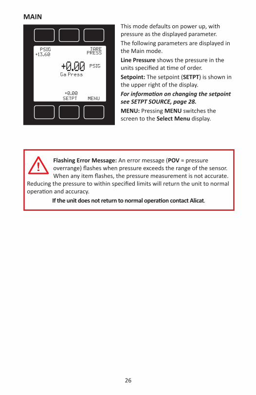
MAIN This mode defaults on power up, with pressure as the displayed parameter. The following parameters are displayed in the Main mode.Line Pressure shows the pressure in the units specified at time of order.Setpoint: The setpoint (SETPT) is shown in the upper right of the display. For information on changing the setpoint see SETPT SOURCE, page 28.MENU: Pressing MENU switches the screen to the Select Menu display.
MENU
TARE PRESS
PSIG
PSIG+13.60
+0.00SETPT
Flashing Error Message: An error message (POV = pressure overrange) flashes when pressure exceeds the range of the sensor. When any item flashes, the pressure measurement is not accurate.
Reducing the pressure to within specified limits will return the unit to normal operation and accuracy.
If the unit does not return to normal operation contact Alicat.
+0.00Ga Press

27
SELECT MENUFrom Select Menu you can change the selected gas, interact with your RS-232 / RS-485 settings, read manufacturer’s data and access the control setup screen.Press the button next to the desired operation to bring that function to the screen.
An explanation for each screen can be found on the following pages:Control: Please see page 28.About: Please see page 19.Tares: Please see page 32.Main: Please see page 26.Basic Config: Please see page 21. Adv Setup: Please see page 22.
TARES
ADV SETUP
MAIN
ABOUT
MENU
TARE PRESS
PSIG
PSIG+13.60
+0.00 SETPT
BASIC CONFIG
DEVICE STATE
BACK MAIN
MFG INFO
DEVICE INFO
COMMSETUP
BACK MAIN
SENSOR SETUP
DEVICEUNITS
BACK MAIN
BACK MAIN
TARE PRESS
DISP SETUP
ADVSETUP
TARESABOUT
MAIN
CONTROL
BASIC CONFIG
Select Menu
+ 13.60Ga Press
CONTROL
LOOPVAR
BACK PID MAIN
SETPTSOURCE
SETPT+0.00
28
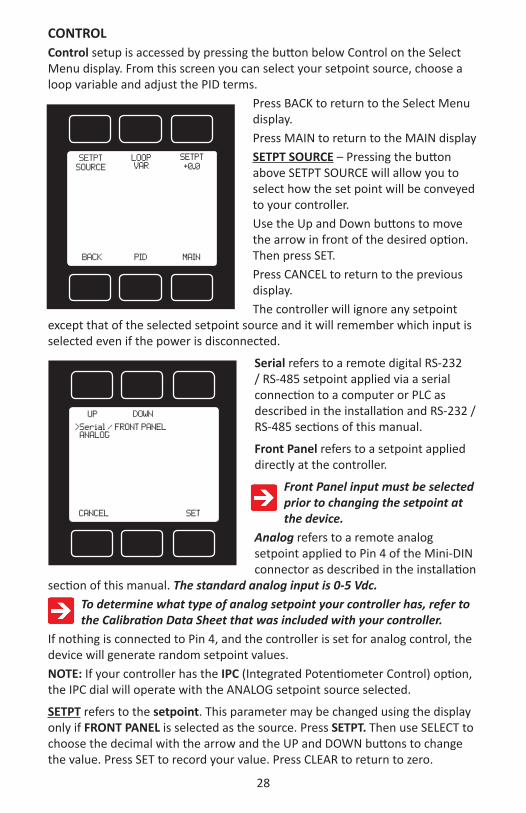
CONTROL Control setup is accessed by pressing the button below Control on the Select Menu display. From this screen you can select your setpoint source, choose a loop variable and adjust the PID terms.
Press BACK to return to the Select Menu display. Press MAIN to return to the MAIN displaySETPT SOURCE – Pressing the button above SETPT SOURCE will allow you to select how the set point will be conveyed to your controller. Use the Up and Down buttons to move the arrow in front of the desired option. Then press SET.Press CANCEL to return to the previous display. The controller will ignore any setpoint
except that of the selected setpoint source and it will remember which input is selected even if the power is disconnected.
Serial refers to a remote digital RS-232 / RS-485 setpoint applied via a serial connection to a computer or PLC as described in the installation and RS-232 / RS-485 sections of this manual.
Front Panel refers to a setpoint applied directly at the controller.
Front Panel input must be selected prior to changing the setpoint at the device.
Analog refers to a remote analog setpoint applied to Pin 4 of the Mini-DIN connector as described in the installation
section of this manual. The standard analog input is 0-5 Vdc. To determine what type of analog setpoint your controller has, refer to the Calibration Data Sheet that was included with your controller.
If nothing is connected to Pin 4, and the controller is set for analog control, the device will generate random setpoint values. NOTE: If your controller has the IPC (Integrated Potentiometer Control) option, the IPC dial will operate with the ANALOG setpoint source selected.
SETPT refers to the setpoint. This parameter may be changed using the display only if FRONT PANEL is selected as the source. Press SETPT. Then use SELECT to choose the decimal with the arrow and the UP and DOWN buttons to change the value. Press SET to record your value. Press CLEAR to return to zero.
DOWN
CANCEL SET
UP
>Serial / FRONT PANEL ANALOG
LOOPVAR
BACK PID MAIN
SETPTSOURCE
SETPT+0.0

29
CAUTION! Never leave a Controller with a non-zero setpoint if no pressure is available to make flow. The controller will apply full power to the valve in an attempt to reach the setpoint. When there is no flow, this can make the valve very HOT!
CONTROL (continued)LOOP VAR—Pressing the LOOP VAR button on the Control Setup screen will allow you to control on absolute pressure or gauge pressure if the device contains a barometer. Use the Up and Down buttons to move the arrow in front of the desired option.
DOWN
CANCEL SET
UP
>Abs Pressure Gauge Pressure
LOOPVAR
BACK PID MAIN
SETPTSOURCE
SETPT+0.0

30
PID TUNING
PID Values determine the performance and operation of your proportional control valve. These terms dictate control speed, control stability, overshoot and oscillation. All units leave the factory with a generic tuning designed to handle most applications. If you encounter issues with valve stability, oscillation or speed, fine tuning these parameters may resolve the problem.Alicat controllers allow you to adjust the Proportional, Integral and Differential terms of the PID control loop. To change the PID loop parameters, push the button below PID.Press LOOP TYPE. Then use the UP and DOWN buttons to select the appropriate PID control algorithm. Press SET.See the following page for descriptions of the PID Loop Types (PID Control Algorithms).
P refers to the Proportional term of the PID loop. I refers to the Integral term of the PID loop. D refers to the Differential term of the PID loop. Press P, I or D. Then use SELECT to choose the digit with the arrow and the UP and DOWN buttons to change the value. Press SET to record your value. Press CLEAR to return to zero.
Before changing the P, I or D parameter, please record the initial value so that it can be returned to
the factory setting if necessary.Valve tuning can be complex. If you would like assistance, please contact Alicat for technical support.
I00500
BACKLOOP TYPE MAIN
P00100
D05000
LOOPVAR
PID MAIN
SETPTSOURCE
SETPT+0.0
Overview of PID Adjustment on Alicat MFCs and Pressure Controllershttp://www.alicat.com/support/instructional-videos/
BACK
DOWN
CANCEL SET
UP
> PD /PDF CONTROL PD2I CONTROL

31
The PD algorithm is the PID algorithm used on most Alicat controllers.It is divided into two segments:The first compares the process value to the setpoint to generate a proportional error. The proportional error is multiplied by the ‘P’ gain, with the result added to the output valve drive. The second operates on the present process value minus the process value during the immediately previous evaluation cycle. This ‘velocity’ term in multiplied by the ‘D’ gain, with the result subtracted from the output valve drive. The above additions to and subtractions from the output drive register are carried over from process cycle to process cycle, thus performing the integration function automatically. Increasing the ‘P’ gain will promote the tendency of the system to overshoot, ring, or oscillate. Increasing the ‘D’ gain will reduce the tendency of the system to overshoot. The PD2I algorithm is a PID algorithm used primarily for high performance pressure and flow control applications. It exhibits two basic differences from the PD algorithm that most controllers utilize.
1. Instead of applying a damping function based upon the rate of change of the process value, it applies a damping function based upon the square of the rate of change of the process value.2. The damping function is applied directly to the proportional error term before that term is used in the proportional and integral functions of the algorithm. This provides a certain amount of ‘look ahead’ capability in the control loop.
Because of these differences, you will note the following:1. Increasing ‘P’ gain can be used to damp out overshoot and slow oscillations in pressure controllers. You will know that ‘P’ gain is too high, when the controller breaks into fast oscillations on step changes in setpoint. On flow controllers, too low a ‘P’ gain results in slower response times. Too high a ‘P’ gain results in overshoot and/or slow oscillation. A good starting value for ‘P’ gain is 200.2. If the unit was originally shipped with the PD2I algorithm selected, the ‘D’ gain value should be left at or near the factory setting because it relates primarily to the system phase lags. If you are changing from the default algorithm to the PD2I algorithm, you should start with a ‘D’ gain value of 20.3. The ‘I’ gain is used to control the rate at which the process converges to the setpoint, after the initial step change. Too low a value for ‘I’ gain shows up as a process value that jumps to near the setpoint and then takes awhile to converge the rest of the way. Too high a value for ‘I’ gain results in oscillation. A good starting value for the ‘I’ gain is 200.
32
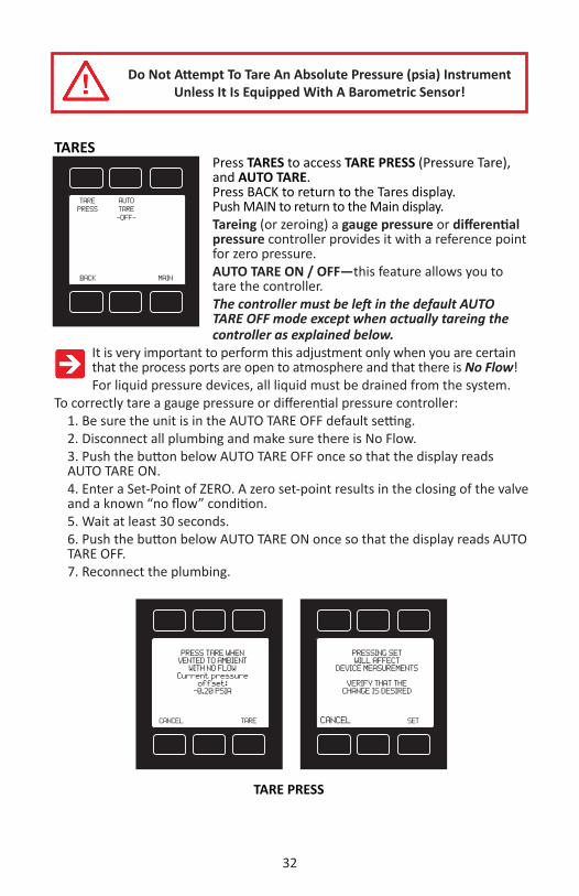
Do Not Attempt To Tare An Absolute Pressure (psia) Instrument Unless It Is Equipped With A Barometric Sensor!
TARESPress TARES to access TARE PRESS (Pressure Tare), and AUTO TARE.Press BACK to return to the Tares display.Push MAIN to return to the Main display.Tareing (or zeroing) a gauge pressure or differential pressure controller provides it with a reference point for zero pressure. AUTO TARE ON / OFF—this feature allows you to tare the controller.The controller must be left in the default AUTO TARE OFF mode except when actually tareing the controller as explained below.
It is very important to perform this adjustment only when you are certain that the process ports are open to atmosphere and that there is No Flow! For liquid pressure devices, all liquid must be drained from the system.
To correctly tare a gauge pressure or differential pressure controller:1. Be sure the unit is in the AUTO TARE OFF default setting.2. Disconnect all plumbing and make sure there is No Flow.3. Push the button below AUTO TARE OFF once so that the display reads AUTO TARE ON.4. Enter a Set-Point of ZERO. A zero set-point results in the closing of the valve and a known “no flow” condition.5. Wait at least 30 seconds.6. Push the button below AUTO TARE ON once so that the display reads AUTO TARE OFF.7. Reconnect the plumbing.
AUTO TARE-OFF-
BACK MAIN
TAREPRESS
CANCEL SET
PRESSING SET WILL AFFECT
DEVICE MEASUREMENTS
VERIFY THAT THE CHANGE IS DESIRED
CANCEL TARE
PRESS TARE WHENVENTED TO AMBIENT
WITH NO FLOWCurrent pressure
offset:-0.20 PSIA
TARE PRESS

33
FLOW
Alicat Precision Pressure Controller
Pressure Control Application, Upstream Valve
Back Pressure Control Application, Downstream Valve (DS)Specify DS in part number adder code
Mechanical Pressure Regulator
Mechanical Pressure Regulator
Vent Flow
FLOW
Alicat Precision Pressure Controller
Process
ProcessFlow ExitingBleed Port
Upstream and Downstream Valve Diagram
Changing Valve Position On Alicat Small Valve Mass Flow And Pressure Controllershttp://www.alicat.com/support/instructional-videos/
34
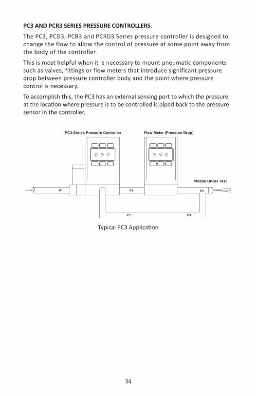
PC3 AND PCR3 SERIES PRESSURE CONTROLLERS:
The PC3, PCD3, PCR3 and PCRD3 Series pressure controller is designed to change the flow to allow the control of pressure at some point away from the body of the controller.
This is most helpful when it is necessary to mount pneumatic components such as valves, fittings or flow meters that introduce significant pressure drop between pressure controller body and the point where pressure control is necessary.
To accomplish this, the PC3 has an external sensing port to which the pressure at the location where pressure is to be controlled is piped back to the pressure sensor in the controller.
P1
P3
P3 P3 P3
P3
P3P2
Nozzle Under Test
Flow Meter (Pressure Drop)PC3 Series Pressure ControllerPC3-Series Pressure Controller Flow Meter (Pressure Drop)
Nozzle Under Test
P1 P2
P3 P3
P3
Typical PC3 Application

35
DIFFERENTIAL PRESSURE GAUGES:
The differential pressure gauge is designed to measure a pressure difference between two points in the line. There are a variety of applications for this device.
One of the most common is to measure the difference in pressure across some sort of element that changes resistance to flow over time, such as a filter, or one that changes area with time as would happen with orifice testing.
The gauge has two sensing ports which are piped to the upstream and downstream sides of the pressure drop of interest in the system.
These two ports run either to two separate pressure sensors or for low differential pressures – they may be run to the two legs of a single differential pressure sensor. The higher (upstream) pressure is applied to the left port and the lower (downstream) pressure is applied to the right port.
P1
P2
Differential Pressure Gauge Application

36
DIFFERENTIAL PRESSURE CONTROLLERS:
The differential pressure controller is designed to change the flow to allow the control of a pressure difference between two points in the line. There are a variety of applications for this device.
One of the most common is to control the difference in pressure across some sort of element that changes resistance to flow over time, such as a filter or one that changes area with time as would happen with orifice testing. To accomplish differential pressure control, the controller has two sensing ports which are piped to the upstream and downstream sides of the pressure drop in the system.
These two ports run either to two separate pressure sensors or for low differential pressures – they may be run to the two legs of a single differential pressure sensor. The controller itself changes the flow to the two sensing ports until the difference between the two pressures matches the set-point.
P2P1
P2P1 P2P1
Differential Pressure Controller Application

37
PCD-SERIES DUAL VALVE PRESSURE CONTROLLER OPERATIONAlicat Scientific PCD-Series Closed Volume Pressure Controllers incorporate a digital pressure gauge with dual control valves and circuitry. The integrated PID loop measures the pressure, compares it with the setpoint, and adjusts either the Inlet or Exhaust valve accordingly at one thousand times per second. It is most common to have a .050 inch diameter orifice in the inlet valve, and a .050 inch diameter exhaust valve. The response time of the system will depend on the size of the volume being controlled and the feed pressure. The controllers are intended for use with clean, non-corrosive gases only. They are designed with a feed port, a process port, and an exhaust port. This allows the controllers to raise and lower the pressure of a closed system within the operating range of the controller without wasting gas under constant pressure conditions.PlumbingConnect your PCD into your process via the 1/8” NPT port on the front of the unit. This is the “Process” port. Connect a supply pressure greater than the full scale pressure control range of the device to the inlet 1/8” NPT port on the left side device. This is the “Inlet” port. The 1/8” NPT “Exhaust” port, located on the right side of the device can vent to atmosphere if the application is suitable, or to a collection network if necessary. The pressure at the exhaust port should be at atmospheric pressure or below to allow the controller to be used over its full scale range. If desired, there are two 8-32 mounting holes located on the bottom of the unit as shown in the dimensional drawing on page 61. Connect your PCD to power and output lines as detailed on pages 9 - 12.
Supply Pressure
Closed Volume
Decrease Pressure
Exhaust
Increase Pressure
Typical PCD Plumbing Diagram

38
RS-232 / RS-485 Output and InputAlicat flow and pressure units come standard with Alicat’s integrated multi-drop RS-232 connectivity; although, RS-485 can be substituted.
Alicat’s Flow Vision SoftwareFlow Vision is an affordable software program that interfaces with RS-232 or RS-485 and is compatible with most Alicat flow and pressure instruments. The graphical user interface (GUI) provides automatic configuration, session saving for easy configuration and experiment setup reloads, data capturing and logging (including a graphing tool), simple script building for automating meter and control command sequences, software alarms, and support for multiple devices.Flow Vision SC™ is for general use with up to 26 different Alicat devices, while Flow Vision MX™ is specifically designed for gas mixing applications.
Alicat’s Free Serial Terminal ApplicationSerial Terminal was written by Alicat as a preconfigured program for RS-232 or RS-485 communication with Alicat devices and can be downloaded from www.alicat.com/support/software-drivers. Serial Terminal requires a Microsoft®.Net Framework to run properly which is usually preinstalled on the PC. Once downloaded, simply run SerialTerminal.exe and enter the COM port number and baud rate of your Alicat device as prompted. The COM port number may be determined using the Device Manager on the computer, and the default baud rate of an Alicat device is 19200.
Additional Programs that are compatible with Alicat productsAlicat products are compatible with many serial communication type software packages including PuTTy and LabVIEW. A brief set of instructions for each of these programs is available at www.alicat.com/support/software-drivers.Many other programs are also compatible with Alicat devices. To set up serial communication it is important to note which COM port the Alicat is connected to and the communication settings required. The default communication settings are as follows: baud rate = 19200, data bits = 8, stop bits = 1, parity = none, and flow control = none. Not all programs have these options and care should be taken to determine the proper communication setup with the desired program.Alicat has written drivers specifically for LabVIEW which are available for download at www.alicat.com/support/software-drivers.
Sending a CommandIn this section, a command will be denoted with a different font. For example, command<CR>. <CR> will be used to symbolize a carriage return. How a carriage return is entered is dependent on the serial communication program being used. With Serial Terminal, this can commonly be accomplished by pressing “Enter” or “Return”. Parenthesis denote a value that must be filled in by the user. For example,(unit ID)<CR> should be changed to A<CR> when using a
39
device with Unit ID “A”. It may also be useful to note that commands are case insensitive. For example, A<CR> is equivalent to a<CR>.
Polling ModeAll Alicat devices are sent in Polling Mode with Unit ID A unless otherwise requested. Polling a device will return a data frame of the current measurements in the device in units shown on the display. See Data Format, later in this section, for more information. Each unit may be polled individually using the command (unit ID)<CR>. A device’s Unit ID may be changed using the command (current unit ID)@=(desired unit ID)<CR>. The Unit ID can also be changed via the front panel using the RS-232 / RS-485 communication select menu. Care should be taken not to assign the same unit ID to more than one device on a single COM port. Up to 26 units may be connected simultaneously as Unit IDs between A and Z are allowed.
Streaming Mode (RS-485 units do not have streaming mode)
In Streaming Mode, a device will automatically output the data stream at a pre-determined rate. The default rate is set to 50 ms and can be changed via register values for units with software version 4v30 or newer. Only one unit on a given COM port may be in streaming mode at a time.To change a unit from Polling Mode to Streaming Mode, type (unit ID)@=@<CR>. This is equivalent to changing the unit ID to “@”. If data does not appear, check all the connections and COM port settings.
When sending a command to a unit in streaming mode, the flow of information will not stop while the user is typing; and the typed text may not be readable depending on the terminal settings. If the unit does not receive a valid command, it will ignore it. If in doubt, simply perform another carriage return and start again.To change a unit from Streaming Mode to Polling Mode, type @@=(unit ID)<CR>. If entered correctly, the data stream will stop and the device will now be in polling mode.
Data Format
The data frame on the screen represents the current measurements in the device in the units shown on the display. By default, pressure gauges are configured to output two columns of data, and pressure controllers output three.
All data is displayed in the “device units” selected on the unit. Devices come standard with units of PSIA, PSIG or PSID, depending on the type of the device. Note that the “button units” available on portable units will not affect the serial output. The first column is the unit ID. This column will be excluded if the device is in streaming mode. The next column is pressure, and on controllers, a third column of setpoint will be displayed.
40
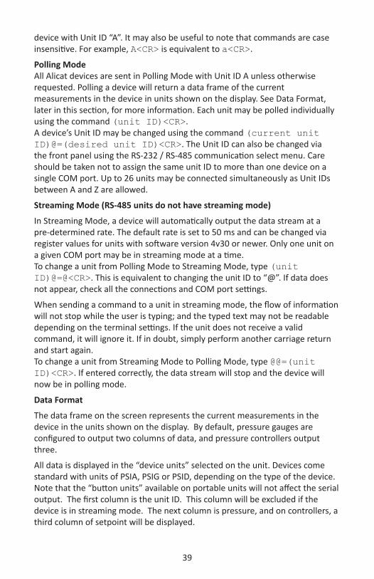
For example, suppose a gauge with unit ID A was ordered with units of inHgG or the “device units” are currently selected as inHgG. The data frame may read:
A +50.42Unit ID Pressure
P-Series Pressure Gauge Data Format
Similarly, a controller with unit ID A in the same conditions, with a setpoint value set to 50.42 inHgG will have a data frame that may read:
A +50.42 50.42Unit ID Pressure Setpoint
PC-Series Pressure Gauge Data FormatAdditional columns, including status codes, may be present to the right of the last column.
Sending a Setpoint via RS-232 / RS-485 (Controllers Only)To send a setpoint via RS-232 / RS-485, serial communication must be selected under the “Setpt Source” list in the control set up menu.
Method 1: Setpoint may be set as a floating point number in serial communication using the setpoint command (unit ID)S(floating point number)<CR>. For example, AS4.54<CR> changes the setpoint for unit “A” to 4.54 in the current device units.
Method 2: The setpoint can also be set in reference to a portion of the full scale. Type (unit ID)(integer)<CR>. Values between 0 and 64000 are acceptable, which correspond linearly to 0 and 100% full scale pressure respectively.
Once a setpoint is accepted, the data frame will be returned with the setpoint column changed accordingly. If no change is observed, make sure that “Analog” is not the selected “Setpt Source” in the Control Setup menu.
The formula for performing linear interpolation is as follows:
Value = (desired setpoint) X 64000 / (full Scale)
For example, when changing the setpoint on a 100 PSIG full scale controller to 35 PSIG, the following value should be entered:
22400 = (35 PSIG) X 64000 / (100 PSIG)
Additional Serial CommandsFor more advanced serial communication commands, please contact Alicat or view the User’s Guide to Advanced Serial Programming at Alicat.com/knowledge/documents-resources
41
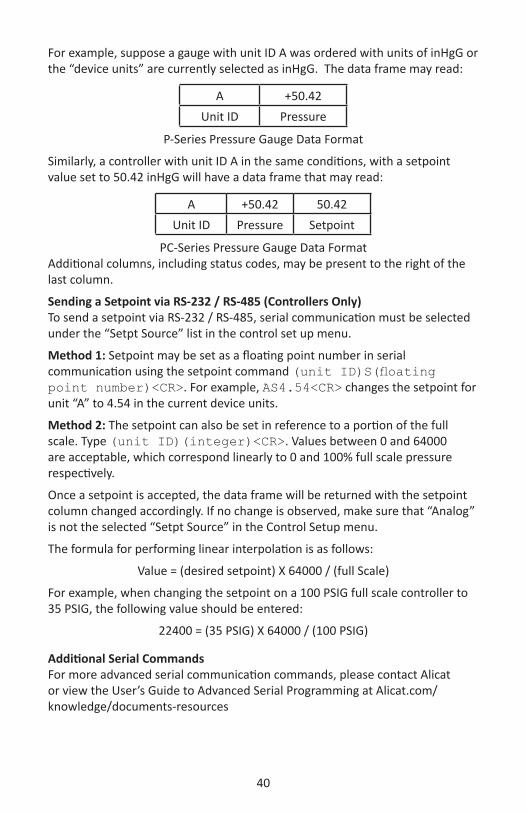
Supported Units: This device supports many different units. You may select the desired units (see page 21). Note that only units appropriate to this device are available for selection.
Pressure UnitsAbsolute Gauge Differential Notes
PaA PaG PaD pascalhPaA hPaG hPaD hectopascalkPaA kPaG kPaD kilopascalMPaA MPaG MPaD megapascalmbarA mbarG mbarD millibarbarA barG barD bar
g/cm2A g/cm2G g/cm2D gram force per square centimeterkg/cmA kg/cmG kg/cmD kilogram force per square centimeter
PSIA PSIG PSID pound force per square inchPSFA PSFG PSFD pound force per square foot
mTorrA mTorrG mTorrD millitorrtorrA torrG torrD torr
mmHgA mmHgG mmHgD millimeter of mercury at 0 CinHgA inHgG inHgD inch of mercury at 0 C
mmH2OA mmH2OG mmH2OD millimeter of water at 4 C (NIST conventional)mmH2OA mmH2OG mmH2OD millimeter of water at 60 CcmH2OA cmH2OG cmH2OD centimeter of water at 4 C (NIST conventional)cmH2OA cmH2OG cmH2OD centimeter of water at 60 CinH2OA inH2OG inH2OD inch of water at 4 C (NIST conventional)inH2OA inH2OG inH2OD inch of water at 60 C
atm atmospherem asl meter above sea level (only in /ALT builds)ft asl foot above sea level (only in /ALT builds)
V volt; no conversions are performed to or from other unitscount count count setpoint count, 0 – 64000
% % % percent of full scale
Valve Drive UnitsLabel Notescount +/- 65536 at full drive
% Percent of full scale drive

42
TROUBLESHOOTINGDisplay does not come on or is weak.Check power and ground connections and supply voltage. Please reference the technical specifications (pages 51-68) to assure you have the proper power for your model.Pressure reading is approximately fixed either near zero or near full scale regardless of actual line pressure.Differential pressure sensor may be damaged. A common cause of this problem is instantaneous application of high-pressure gas as from a snap acting solenoid valve upstream of the meter. If you suspect that your pressure sensor is damaged please discontinue use of the controller and contact Alicat.Displayed pressure is flashing and message POV is displayed:Our pressure gauges and controllers display an error message (POV = pressure overrange) when a the pressure exceeds the range of the sensors in the device. When any item flashes on the display, the pressure measurement is not accurate. Reducing the pressure to within specified limits will return the unit to normal operation and accuracy. If the unit does not return to normal contact Alicat.My controller does not respond to the setpoint.Check that your setpoint signal is present and supplied to the correct pin and that the correct set-point source is selected under the SETPT SOURCE list in the control set up display (page 28). Also check that the unit is properly grounded. After installation, there is no pressure.Alicat Scientific PC-Series Controllers incorporate normally closed valves and require a setpoint to operate. Check that your setpoint signal is present and supplied to the correct pin and that the correct input is selected under the SETPT SOURCE list in the control set up display (page 28). Also check that the unit is properly grounded.The pressure lags below the set-point.Be sure there is enough pressure available. If either the set-point signal line and/or the output signal line is relatively long, it may be necessary to provide heavier wires (especially ground wiring) to negate voltage drops due to line wire length. An inappropriate PID tuning can also cause this symptom if the D term is too large relative to the P term. See pages 30 and 31 for more information on PID tuning.Controller is slow to react to a set-point change or imparts an oscillation to the flow.An inappropriate PID tuning can cause these symptoms. Use at conditions considerably different than those at which the device was originally set up can necessitate a re-tuning of the PID loop. See pages 30 and 31 for more information on PID tuning. Note: The larger the volume pressured, the longer it takes to change the pressure in that volume.The output signal is lower than the reading at the display.This can occur if the output signal is measured some distance from the gauge/controller as voltage drops in the wires increase with distance. Using heavier gauge wires, especially in the ground wire, can reduce this effect.My controller oscillates wildly and/or exhibits very different reactions to the set-point than I expect.Conditions considerably different than those at which the device was originally set up can necessitate a re-tuning of the PID loop. See pages 30 and 31 for more information on PID tuning.

43
RS-232 / RS-485 Serial Communications is not responding.Check that your gauge is powered and connected properly. Be sure that the port on the computer to which the gauge is connected is active. Confirm that the port settings are correct per the RS-232 / RS-485 instructions in this manual (Check the RS-232 / RS-485 communications select screen for current gauge readings). Close HyperTerminal® and reopen it. Reboot your PC. See pages 11, 12 and 38 for more information on RS-232 / RS-485 signals and communications.Slower response than specified.P-Series Gauges and PC-Series Controllers feature an RS-232 / RS-485 programmable Geometric Running Average (GRA). Depending on the full scale range of the gauge, it may have the GRA set to enhance the stability/readability of the display, which would result in slower perceived response time. Please see “Pressure Averaging” on page 22.Jumps to zero at low pressure.P-Series Gauges and PC-Series Controllers feature an RS-232 / RS-485 programmable zero deadband. The factory setting is usually 0.5% of full scale. This can be adjusted between NONE and 6.3% of full scale. See page 22.
MAINTENANCE AND RECALIBRATIONGeneral: P, PC, PCR and PCD-Series Pressure Gauges and Controllers require minimal maintenance. They have no moving parts. The single most important thing that affects the life and accuracy of these devices is the quality of the gas being measured. The instruments are designed to measure CLEAN, DRY, NON-CORROSIVE gases. If your application requires an aggressive or corrosive gas, please consider Alicat’s PS, PCS, PCRS and PCDS Series instruments (see page 64).Recalibration: The recommended period for recalibration is once every year. A label located on the back of the controller lists the most recent calibration date. The controller should be returned to the factory for recalibration within one year from the listed date. Before calling to schedule a recalibration, please note the serial number on the back of the meter. The Serial Number, Model Number, and Date of Manufacture are also available on the Model Info display (page 19).Cleaning: P, PC, PCR and PCD-Series Pressure Gauges and Controllers require no periodic cleaning. If necessary, the outside of the controller can be cleaned with a soft dry cloth. Avoid excess moisture or solvents.For repair, recalibration or recycling of this product, contact:
Alicat Scientific, Inc.7641 N Business Park Drive
Tucson, Arizona 85743USA
Ph. 520-290-6060Fax 520-290-0109
email: [email protected] site: www.alicat.com

44
Alicat Portable Meters and GaugesAlicat Rechargeable Flow Meters and Pressure Gauges use a Li-Ion 3.7V cell located in the top section of the device. The Li-Ion cell must not be removed.Normal battery life of a fully-charged cell is 18 hours with a monochrome display or 5 hours with a TFT color display, when the backlight is set to 10. Dimming the backlight will increase battery life.The battery can be charged through either the micro-USB port or the mini-DIN connector. When the device is connected to external power it will function normally while the battery is charging. Note: If the battery has no charge, a charge time of one minute will be required before the unit can be turned on. Charge rates will be fastest through the micro-USB port using the included power supply or equivalent. The device will charge fastest when it is turned off. Recharge Time: 3.5 hours with 2A USB supply. The micro-USB port is for charging purposes only.The green/red indicator LED on top of the device will light up green to indicate that the unit is charging. The green LED will turn off when the battery is charged and the power switch is turned to “I” for ON. A small lightning bolt symbol will display next to the battery symbol while the device is charging. it will no longer appear when the device is fully charged.The indicator LED flashes red when the device has about 1 hour of battery life remaining. The LED will flash red at a faster rate when the device has about 15 minutes of battery life remaining. It is highly recommended that the device be charged immediately. When the battery charge runs out, the display contrast will turn to 0 and device performance is no longer guaranteed.
Output signals from the meter are passed through the mini-DIN connector on top of the device. Rechargeable battery units do not support 0-10V analog output. Receiver resistance must be below 250Ω.
Turn the power switch on top of the device to “O” for OFF when it is not in use.Warning: If the device is left ON until the battery can no longer power it, the charge indicator will fall out of sync with the actual charge. The device can be re-synced by fully charging the battery once.
A Battery Charge Indicator appears below Tare on the display.
CAUTION! Do not operate or store the device outside of the -10° to +50°C temperature range. If internal sensors detect that the temperature is outside of this range, the display contrast will turn to 0 and the meter’s performance is no longer guaranteed.
The safe charging temperature range is 0° to +45°C. If internal sensors detect temperatures outside of this range, the battery will not charge.
#C+21.50
+0.000CCM MENU
TARE VPSIA+13.60
+0.000SCCM
95 – 100%
80 – 95%
50 – 80%
20 – 50%
5 – 20%
0 – 5%
TOP VIEW OF DEVICE
Green = ChargingFlashing Red = Low Battery
+5 VdcCharge Only
1 2
3 4 56 7 8 I
O
On / Off I / O

45
Pressure Menu for Portable Meters Alicat portable gauges are programmed with additional pressure read options. Pressing the pressure button once (upper left) will move the pressure reading to the main display. Pressing the button a second time will open a menu of pressure read options. Scroll UP or Down and press Select to make a change.
When the pressure button is already using the device engineering units, the bottom menu option displays as “Set device eng units”.When the pressure button is using something different than device engineering units (e.g., bar instead of PSI), the bottom menu option displays as “Show device units”.The serial data line changes only when device engineering units are changed, and the instrument will prompt you to accept these changes to the serial line.
Tare PRESS: The stream absolute pressure sensor can be tared to the barometric pressure sensor. In this case, the absolute pressure is offset by the differential between the two readings. Tare PRESS can be accessed from the TARES display.
MENUL
TAREPRESS
PSIA+13.60
+13.60Abs Press
DOWN
BACK SELECT
>Show abs pressure Show gauge pressure Show baro pressure Set button eng units Set device eng units
UP
PSIA
VENT TO ATMOSPHEREWITH NO FLOW BEFORE
PRESSING SET.Current absolute
sensor offset:+0.000 barG
CANCEL TARE
46
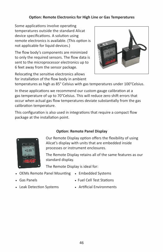
Option: Remote Electronics for High Line or Gas Temperatures
Some applications involve operating temperatures outside the standard Alicat device specifications. A solution using remote electronics is available. (This option is not applicable for liquid devices.)
The flow body’s components are minimized to only the required sensors. The flow data is sent to the microprocessor electronics up to 6 feet away from the sensor package.
Relocating the sensitive electronics allows for installation of the flow body in ambient temperatures as high as 85° Celsius with gas temperatures under 100°Celsius.
In these applications we recommend our custom gauge calibration at a gas temperature of up to 70°Celsius. This will reduce zero shift errors that occur when actual gas flow temperatures deviate substantially from the gas calibration temperature.
This configuration is also used in integrations that require a compact flow package at the installation point.
Option: Remote Panel Display
Our Remote Display option offers the flexibility of using Alicat’s display with units that are embedded inside processes or instrument enclosures.
The Remote Display retains all of the same features as our standard display.
The Remote Display is ideal for:
OEMs Remote Panel Mounting Embedded Systems
Gas Panels Fuel Cell Test Stations
Leak Detection Systems Artificial Environments

47
Accessory: BB9 Multi-Drop Box
The BB9 Multi-Drop Box makes it convenient to wire multiple flow and/or pressure devices to a single RS-232 or RS-485 port. Now with an RS-232 to USB interface!
The Multi-Drop Box has nine 8 pin Mini-DIN ports available. The ports are to be used with a standard double ended 8 pin Mini-DIN (DC-62) style cable going from the box to each flow or pressure device. (The BB9 can also be ordered with locking industrial connectors.)
A single DB9 D-SUB type connector (COM PORT) connects, using the included cable, to the serial connector on a PC or laptop.
All of the flow and/or pressure devices are powered via a terminal block on the front of the box.
If more than nine devices will be required, additional Multi-Drop Boxes can be daisy chained together with a double ended 8 pin Mini-DIN cable plugged into any receptacle on both boxes.
BB9 Power Supply for Large Valve Controllers: The PS24VHC (Power Supply 24Vdc High Current) is a 6.5Amp 24Vdc power supply designed for running multiple large controllers on a BB9.
The 6.5Amp power supply can run as many as 8 large valve controllers, which makes it ideal for the BB9 and multiple large valve (or small valve / large valve combination) controllers on a BB9.
BB-9 Multi-Drop BoxØ .156 Thru 4 Places
1.75
Ø .340 Thru 2 PL
3.46
6.75 1.55
5.06
BB9 Multi-Drop Box
Ø .156 Thru 4 Places
1.75
Ø .340 Thru 2 PL
Ø .175 Thru 2 PL
3.46
6.75 1.55
5.06
6.75
7.56

48
Accessory: Flow Vision™ SC SoftwareFlow Vision™ SC is an intuitive software interface to help your test cycles run smoother and shorten your engineering time!
Flow Vision™ SC lets you connect to and communicate with multiple Alicat units simultaneously. Now you can view virtual displays, control tabs, charts and data lines from every connected Alicat device on the same screen.
Flow Vision™ SC supports all RS-232 and RS-485 Serial communication functions, including: gas selection, tareing, set-point control, valve tuning and flow averaging.Session Saving: Save and reload your configuration data with confidence. Script Building: Create scripts to adjust a controller’s set-point value at variable specified time intervals.Charting: Chart as many parameters as you want off as many devices as you want, with color coding, zooming, and printing functionality.Alarms: Create software alarms that will notify you of given parameter conditions.Data Capture & Logging: Capture and log data to either a .csv file or a .txt file. Improved Data Logging and Data Log File Splitting for easy to manage data.
Accessory: Flow Vision™ MX SoftwareAlicat’s New Flow Vision™ MX software gives you an easy way to do GAS BLENDING using Alicat Mass Flow Controllers and your own PC.
Flow Vision™ MX software is a simple way to connect up to six Alicat mass flow controllers and create your own gas mix concentrations.
Using our inexpensive BB9-232 and a single USB connection you can:
• Create your own gas blends • Adjust flow rates • Save your specific blend formulas.
All the controllers can be powered through the BB9-232 with a single power supply.
Just connect your unique gases to each controller, select the gas type either locally on the controller or through Flow Vision™ MX, manifold the flow outputs and create your gas mix.
49
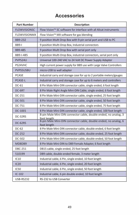
AccessoriesPart Number Description
FLOWVISIONSC Flow Vision™ SC software for interface with all Alicat instruments
FLOWVISIONMX Flow Vision™ MX software for gas blending
BB9-232 9 position Multi Drop Box with 9-pin serial port and USB to PC
BB9-I 9 position Multi-Drop Box, Industrial connectors
BB9-485 9 position Multi Drop Box with serial port only
BB9-I-485 9 position Multi-Drop Box, industrial connectors, serial port only
PVPS24U Universal 100-240 VAC to 24 Volt DC Power Supply Adapter
PS24VHC High current power supply for BB9 use with Large Valve Controllers
PVPS5USBU micro-USB to wall adapter
PCASE Industrial carry and storage case for up to 2 portable meters/gauges
PCASE-L Industrial carry and storage case for up to 6 meters and controllers
DC-61 8 Pin Male Mini-DIN connector cable, single ended, 6 foot length
DC-6RT 8 Pin Male Right Angle Mini-DIN Cable, single ended, 6 foot length
DC-251 8 Pin Male Mini-DIN connector cable, single ended, 25 foot length
DC-501 8 Pin Male Mini-DIN connector cable, single ended, 50 foot length
DC-751 8 Pin Male Mini-DIN connector cable, single ended, 75 foot length
DC-1001 8 Pin Male Mini-DIN connector cable, single ended, 100 foot length
DC-32RS 8-pin Male Mini-DIN connector cable, double ended, no analog, 3 foot length
DC-62RS 8-pin Male Mini-DIN connector cable, double ended, no analog, 6 foot length
DC-62 8 Pin Male Mini-DIN connector cable, double ended, 6 foot lengthDC-252 8 Pin Male Mini-DIN connector cable, double ended, 25 foot lengthDC-502 8 Pin Male Mini-DIN connector cable, double ended, 50 foot length
MD8DB9 8 Pin Male Mini-DIN to DB9 Female Adapter, 6 foot length
DBC-251 DB15 cable, single ended, 25 foot length
510199 DB9 cable, double-ended female, 3 meter length
IC10 Industrial cable, 6 Pin, single ended, 10 foot length
IC20 Industrial cable, 6 Pin, single ended, 20 foot length
IC50 Industrial cable, 6 Pin, single ended, 50 foot length
IC-102 Industrial cable, 6 pin double ended, 10 foot length
USB-RS232 RS-232 to USB Converter
50
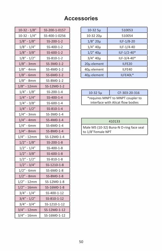
10-32 - 1/8” SS-200-1-015710-32 - 1/4” SS-400-1-02561/8” - 1/8” SS-200-1-21/8” - 1/4” SS-400-1-21/8” - 3/8” SS-600-1-21/8” - 1/2” SS-810-1-21/8” - 3mm SS-3M0-1-21/8” - 4mm SS-4M0-1-21/8” - 6mm SS-6M0-1-21/8” - 8mm SS-8M0-1-2
1/8” - 12mm SS-12M0-1-21/4” - 1/8” SS-200-1-41/4” - 1/4” SS-400-1-41/4” - 3/8” SS-600-1-41/4” - 1/2” SS-810-1-41/4” - 3mm SS-3M0-1-41/4” - 4mm SS-4M0-1-41/4” - 6mm SS-6M0-1-41/4” - 8mm SS-8M0-1-4
1/4” - 12mm SS-12M0-1-41/2” - 1/8” SS-200-1-81/2” - 1/4” SS-400-1-81/2” - 3/8” SS-600-1-81/2” - 1/2” SS-810-1-81/2” - 3/4” SS-1210-1-81/2” - 6mm SS-6M0-1-81/2” - 8mm SS-8M0-1-8
1/2” - 12mm SS-12M0-1-81/2” - 16mm SS-16M0-1-83/4” - 1/4” SS-400-1-123/4” - 1/2” SS-810-1-123/4” - 3/4” SS-1210-1-12
3/4” - 12mm SS-12M0-1-123/4” - 16mm SS-16M0-1-12
10-32 5μ 51005310-32 20μ 5100541/8” 20μ ILF-1/8-201/4” 40μ ILF-1/4-401/2” 40μ ILF-1/2-40*3/4” 40μ ILF-3/4-40*
20μ element ILFE2040μ element ILFE4040μ element ILFE40L*
10-32 5μ CF-303-20-316*requires MNPT to MNPT coupler to
interface with Alicat flow bodies
410133
Male M5 (10-32) Buna-N O-ring face seal to 1/8”Female NPT
Accessories

51
Technical Data for P-Series Pressure GaugesStandard Specifications (Contact Alicat for available options.)
Full scale pressure < 2” H2O Accuracy Consult FactoryFull scale pressure ≥ 2” H2O
Standard Accuracy ± 0.25%
Full scale pressure ≥ 2” H2O High Accuracy Option ± 0.125%
Repeatability ± 0.08% Full ScaleZero Shift and Span Shift 0.02% Full Scale / ºCelsius
Operating Range / Turndown Ratio 0.5% to 100% Full Scale / 200:1 TurndownExcess Pressure 128% FS Measurable
Burst Pressure 3 X Full ScaleTypical Response Time1 5 ms (Adjustable)
Warm-up Time < 1 Second1. Volumes, feed pressures, exhaust pressures and line sizing will determine the limits of response times.
Gas Compatibility Compatible with all non-corrosive gases1
Operating Temperature -10 to +60 ºCelsiusCommon Mode Pressure
(Differential Pressure Units Only) 200 psig
Mounting Attitude Sensitivity NoneIngress Protection IP40
Wetted Materials 302 & 303 Stainless Steel, Viton®. Silicone RTV, Silicon, Glass. If your application demands a different material, please contact Alicat.
1. For aggressive gases, please see our PS-Series pressure Gauges. For use with water or other liquids please contact Alicat
Monochrome LCD or Color TFT Display with integrated touchpad Displays Pressure
Digital Output Signal1 Options RS-232 Serial / RS-485 Serial / Modbus / EtherNet IP / DeviceNet / PROFIBUS
Analog Output Signal2 Options 0-5 Vdc / 1-5 Vdc / 0-10 Vdc / 4-20 mA
Optional Secondary Analog Output Signal2 0-5 Vdc / 1-5 Vdc / 0-10 Vdc / 4-20 mA Electrical Connection Options 8 Pin Mini-DIN / 9-pin D-sub (DB9) / 15-pin D-sub (DB15) / 6 pin locking
Supply Voltage 7-30 Vdc (15-30 Vdc for 4-20 mA outputs)Supply Current 0.040 Amp
1. The Digital Output Signal communicates Pressure 2. The Analog Output Signal and Optional Secondary Analog Output Signal communicate Pressure
Mechanical SpecificationsPressure Product Mechanical Dimensions Process Connections1
P-Series Gauges 4.1”H x 2.4”W x 1.1”D 1/8” NPT Female1. Compatible with Swagelok® tube, Parker®, face seal, push connect and compression adapter fittings. VCR and SAE connections upon request.
Select One Unit of Measure when OrderingPSIA inHG Atm
PSIG inH2O Torr
mmHG mBar kPa
Standard Available RangesP-Series Gauges-15 psig to 0 psig
2 inH2OD 2 inH2OG1 psid 1 psig5 psid 5 psig
15 psid 15 psig 15 psia30 psid 30 psig 30 psia
100 psid 100 psig 100 psia500 psig 500 psia
Other ranges available. Please contact Alicat.

52
P-Series:All standard ranges
P-Series:Differential PressureAll standard ranges
60.33mm2.375in
103.30mm4.067in
1P-10PSIG-D
1/6/2016DATE
REV.
26.67mm1.050in
Both Sides1/8 NPT
8.89mm.350in
13.34mm.525in
2.225in56.52mm
8.89mm2X 8-32 UNC .350in
.150in3.81mm
.925in23.50mm
3.18mm.125in
8.89mm.350in
13.34mm.525in
P Series approximate shipping weight: 1.0lb
23.50mm.925in
.150in3.81mm2.225in
56.52mm
.125in3.18mm
2X 8-32 UNC .350in 8.89mm
13.34mm.525in
8.89mm.350in
1/8 NPTBoth Sides
8.89mm.350in
13.34mm.525in
60.33mm2.375in
103.30mm4.067in
26.67mm1.050in
DATE
12/12/2015
P-1PSID-D-MSPEC 1REV.
P Series approximate shipping weight: 1.0lb

53
Technical Data for PC, PC3, PCR, and PCR3 Single Valve Pressure ControllersStandard Specifications (Contact Alicat for available options.)
Full scale pressure < 2” H2O Accuracy Consult FactoryFull scale pressure ≥ 2” H2O Standard Accuracy ± 0.25%
Full scale pressure ≥ 2” H2O High Accuracy Option ± 0.125%
Repeatability ± 0.08% Full ScaleZero Shift and Span Shift 0.02% Full Scale / ºCelsius
Operating Range / Turndown Ratio 0.5% to 100% Full Scale / 200:1 TurndownExcess Pressure 102.4% FS Controllable
Burst Pressure 3 X Full ScaleTypical Response Time1 100 ms (Adjustable)
Warm-up Time < 1 Second1. Volumes, feed pressures, exhaust pressures and line sizing will determine the limits of response times.
Gas Compatibility Compatible with all non-corrosive gases1
Operating Temperature -10 to +60 ºCelsiusCommon Mode Pressure
(Differential Pressure Units Only)
150 psig
Mounting Attitude Sensitivity NoneValve Type Normally Closed
Ingress Protection IP40
Wetted Materials400 Stainless Steel, 302 & 303 Stainless Steel, Viton®. Silicone RTV, Silicon, Glass.PC & PC3 Only Add: BrassIf your application demands a different material, please contact Alicat.
1. For aggressive gases, please see our PCS and PCRS-Series pressure controllers. For use with water or other liquids please contact Alicat
Monochrome LCD or Color TFT Display with integrated touchpad Displays Pressure
Digital Output Signal1 Options RS-232 Serial / RS-485 Serial / Modbus / EtherNet IP / DeviceNet / PROFIBUSAnalog Output Signal2 Options 0-5 Vdc / 1-5 Vdc / 0-10 Vdc / 4-20 mA
Optional Secondary Analog Output Signal2 0-5 Vdc / 1-5 Vdc / 0-10 Vdc / 4-20 mA Electrical Connection Options 8 Pin Mini-DIN / 9-pin D-sub (DB9) / 15-pin D-sub (DB15) / 6 pin locking
Supply Voltage 12-30 Vdc (15-30 Vdc for 4-20 mA outputs) 24-30 VdcSupply Current 0.250 Amp 0.750 Amp
1. The Digital Output Signal communicates Pressure 2. The Analog Output Signal and Optional Secondary Analog Output Signal communicate Pressure
Mechanical SpecificationsPressure Product Mechanical Dimensions Process Connections1
PC & PC3 Controllers 4.1”H x 3.6”W x 1.1”D 1/8” NPT FemalePCR & PCR3 Controllers 5.5”H x 2.9”W x 5.5”D 3/4” NPT Female
1. Compatible with Swagelok® tube, Parker®, face seal, push connect and compression adapter fittings. VCR and SAE connections upon request.
Select One Unit of Measure when OrderingPSIA inHG Atm
PSIG inH2O Torr
mmHG mBar kPa
Standard Available RangesPC, PC3, PCR & PCR3 Controllers
-15 psig to 0 psig2 inH2OD 2 inH2OG
1 psid 1 psig5 psid 5 psig
15 psid 15 psig 15 psia30 psid 30 psig 30 psia
100 psid 100 psig 100 psia500 psig 500 psia
Other ranges available. Please contact Alicat.

54
2.225in56.515mm
3.175mm
23.495mm.925in
2 PLX 8-32 X .360 2
.125in.150in3.810mm
8.890mm.350in
.525in13.335mm
1/8 NPTBoth Sides
1.050in26.670mm
.350in8.890mm
3.588in91.123mm
4.067in103.302mm
1REV.
DATE
12/12/2015
PC-100PSIG-D-MSPEC
26.670mm1.050in
PC-Series:All standard ranges
PC-Series:Differential PressureAll standard ranges
100 sccm to 20 slpm approximate weight: 1.2lb
100 sccm to 20 slpm approximate weight: 1.2lb
23.50mm.925in
2.225in56.52mm
.150in3.81mm .125in
3.18mm
2X 8-32 UNC - 2B .350in 8.89mm
13.34mm.525in
8.89mm.350in
8.89mm.350in
13.34mm.525in
1/8 NPTBoth Sides
22.02mm.867in
4.067in103.30mm
.350in8.89mm
38.30mm1.508in
2X 1/8 NPT
DATE
PC-1PSID-D-MSPECREV.
1
1/6/2016
26.67mm1.050in
91.12mm3.588in

55
1PCR3-15PSIG-D-MSPEC
12/12/2015DATE
REV.
1.875in
73.66mm2.900in
47.63mm
.375in
.750in19.05mm
.150in3.81mm
44.45mm
9.53mm
NPT1/8
67.31mm .328in[8.33mm]4X 8-32 UNC
2.650in
1.750in
133.15mm5.242in
28.45mm1.120in
1.125in28.58mm
3/4 NPTBoth Sdes
1.120in28.45mm
1.125in28.58mm
5.495in139.56mm
13.34mm.525in
.350in8.89mm
1/8 NPT Process Port13.34mm.525in
.350in8.89mm
1/8 NPT Feed Port
3.81mm.150in 3.18mm
.125in
2.225in56.52mm
23.50mm.925in
2X 8-32 UNC .350in 8.89mm
2.013in51.12mm
103.30mm
91.12mm3.588in
4.067in
.350in8.89mm
1/8 NPT Sense Port
1.050in26.67mm
12/12/2015
PC3-1PSIG-D-MSPECREV.
DATE
1
PC3-Series:All standard ranges
PCR3-Series:All standard ranges
100 sccm to 20 slpm approximate weight: 1.2lb
PCR3 approximate weight: 9.0 lb.

56
1PCR-15PSIG-D-MSPEC
DATE
12/12/2015REV.
5.495in139.56mm
1.120in28.45mm
1.125in28.58mm
28.45mm1.120in
3/4" NPTBoth
1.125in28.58mm
2.700in68.58mm
4X 8-32 UNC .328in[8.33mm]
2.900in73.66mm
47.63mm1.875in
9.53mm
5.08mm.200in
.375in
5.617in142.67mm
PCR-Series:Most standard ranges
PCR-Series:Differential Pressure 5 inH2O
PCR approximate weight: 9.0 lb.
PCR approximate weight: 9.0 lb.
3.300in83.82mm
68.58mm2.700in 9.53mm
2.900in73.66mm
5.08mm.200in
.375in
1.875in47.63mm
4X 8-32 UNC .328in[8.33mm]
28.45mm1.120in
1.125in28.58mm
1.125in28.58mm
1.120in28.45mm
Both Sides3/4 NPT
12/12/2015
PCR-5inH2O-D-MSPECREV.1
DATE
38.30mm1.508in
1/8 NPT
22.02mm.867in
18.42mm.725in
5.495in139.56mm

57
Technical Data for PCD, PCD3, PCRD & PCRD3 Dual Valve Pressure Controllers
Mechanical Specifications
Standard Specifications (Contact Alicat for available options.)Full scale pressure < 2” H2O Accuracy Consult Factory
Full scale pressure ≥ 2” H2O Standard Accuracy ± 0.25%Full scale pressure ≥ 2” H2O
High Accuracy Option ± 0.125%
Repeatability ± 0.08% Full ScaleZero Shift and Span Shift 0.02% Full Scale / ºCelsius
Operating Range / Turndown Ratio 0.5% to 100% Full Scale / 200:1 TurndownExcess Pressure 102.4% FS Controllable
Burst Pressure 3 X Full ScaleTypical Response Time1 100 ms (Adjustable)
Warm-up Time < 1 Second1. Volumes, feed pressures, exhaust pressures and line sizing will determine the limits of response times.
Gas Compatibility Compatible with all non-corrosive gases1
Operating Temperature -10 to +60 ºCelsiusCommon Mode Pressure
(Differential Pressure Units Only) 150 psig
Mounting Attitude Sensitivity None Mount with valve cylinder vertical & uprightValve Type Normally Closed
Ingress Protection IP40
Wetted Materials 302 & 303 Stainless Steel, Viton®, Silicone RTV, Brass, 400 Series Stainless Steel, Silicon, Glass. If your application demands a different material, please contact Alicat.
1. For aggressive gases, please see our PCS and PCRS-Series pressure controllers. For use with water or other liquids please contact Alicat
Monochrome LCD or Color TFT Display with integrated touchpad Displays Pressure
Digital Output Signal1 Options RS-232 Serial / RS-485 Serial / Modbus / EtherNet IP / DeviceNet / PROFIBUSAnalog Output Signal2 Options 0-5 Vdc / 1-5 Vdc / 0-10 Vdc / 4-20 mA
Optional Secondary Analog Output Signal2 0-5 Vdc / 1-5 Vdc / 0-10 Vdc / 4-20 mA Electrical Connection Options 8 Pin Mini-DIN / 9-pin D-sub (DB9) / 15-pin D-sub (DB15) / 6 pin locking
Supply Voltage 12-30 Vdc (15-30 Vdc for 4-20 mA outputs) 24-30 VdcSupply Current 0.250 Amp 0.750 Amp
1. The Digital Output Signal communicates Pressure 2. The Analog Output Signal and Optional Secondary Analog Output Signal communicate Pressure
Dual Valve Pressure Controllers Mechanical Dimensions Process Connections1
PCD & PCD3 All Standard Ranges 4.1”H x 4.8”W x 1.1”D 1/8” NPT Female
PCRD & PCRD3 All Standard Ranges 5.5”H x 10.6”W x 2.3”D 3/4” NPT Female
1. Compatible with Swagelok® tube, Parker®, face seal, push connect and compression adapter fittings. VCR and SAE connections upon request.
Select One Unit of Measure when OrderingPSIA inHG Atm
PSIG inH2O Torr
mmHG mBar kPa
Standard Available RangesPCD, PCD3, PCRD, and PCRD3 Controllers
-15 psig to 0 psig2 inH2OD 2 inH2OG
1 psid 1 psig5 psid 5 psig
15 psid 15 psig 15 psia30 psid 30 psig 30 psia
100 psid 100 psig 100 psia500 psig 500 psia
Other ranges available. Please contact Alicat.

58
13.34mm.525in
8.89mm.350in
26.67mm1.050in
121.92mm4.800in
8.89mm.350in
2.769in70.32mm
103.30mm4.067in
1/8 NPT
1/6/2016
PCD-15PSIG-D-MSPEC
REV.
DATE
1
23.50mm.925in
3.438in87.31mm
1.363in34.61mm
.125in3.18mm
2X 8-32 UNC .350in 8.89mm
13.335mm.525in
.350in8.890mm
Both Sides1/8 NPT
PCD-Series:All standard ranges
PCD-Series:Differential PressureAll standard ranges
103.30mm4.067in
52.82mm2.080in .350in
8.89mm
69.10mm2.721in
2X 1/8 NPT
DATE
PCD-1PSID-D-MSPECREV.
1
1/6/2016
8.89mm.350in
13.34mm.525in
1/8 NPTBoth Sides
26.67mm1.050in
121.92mm4.800in
8.89mm.350in
13.34mm.525in
3.18mm.125in1.363in
34.61mm3.438in87.31mm
23.50mm.925in
1/8 NPT
8.89mm.350in
52.82mm2.080in

59
PCRD-Series:All standard ranges
PCD3100PSIG
28.58mm1.125in
28.45mm1.120in
3/4 NPT Both Sides
28.45mm1.120in
10.550in267.97mm
5.495in139.56mm
133.99mm5.275in
3/4 NPT 28.58mm1.125in
28.45mm1.120in
47.63mm1.875in
.200in5.08mm2.700in
68.58mm 7.850in199.39mm
10.350in262.89mm
.375in9.53mm
8X 8-32 UNC .328in 8.33mmDATE
PCRD-100PSIG-D-MSPEC 1
1/6/2016
REV.
57.15mm2.250in
12/12/2015
PCD3-100PSIG-D-MSPEC 1REV.
DATE
8.89mm.350in
1/8 NPTBoth Sides
69.10mm2.721in
87.31mm3.438in
23.50mm.925in
34.61mm1.363in
.125in3.18mm
2X 8-32 UNC .328in 8.33mm
26.67mm1.050in
13.34mm.525in
.350in8.89mm
Both Sides1/8 NPT
103.30mm4.067in
121.92mm4.800in
69.10mm2.721in
8.89mm.350in .525in
13.34mm
.350in8.89mm

60
5.495
3/4 NPT
1/8 NPT
2.150
1.750
10.5505.275
1.125 1.125
1.120
3/4 NPT1.120
1.125
3/4 NPT
.2002.700 .375
1.875
4X 8-32 UNC .328
5.495
2.420 2.250
PCRD3-15PSIG-D-MSPEC 0
3/12/15DATE
REV.
4.800
4.067
.350
2.013
1.050
.525
.350
.525
.350
Both Sides1/8 NPT
3.4381.363 .125
.925
2X 8-32 UNC .350
2.013
.350
1/8 NPTBoth Sides
PCD3-500PSIA-D-MSPEC 0REV.
3/12/15DATE
PCD3500PSIA
PCRD315PSIG

61
Technical Data for Alicat PS Series Pressure and Vacuum GaugesAlicat PS instruments are built for use with aggressive gases. For the most part these instruments maintain the specifications of equivalently ranged P-Series devices. In addition to all non-corrosive gases, PS Gauges are configured to operate with the following aggressive gases. PS Gauge Aggressive Gas Compatibility List :
NO Nitric Oxide to 100%NF3 Nitrogen Triflouride to 100%NH3 Ammonia to 100%NO2 Nitrogen Dioxide to 100%Cl2 Chlorine to 100%H2S Hydrogen Sulfide to 100%SO2 Sulfur Dioxide to 100%Propylene to 100%
In addition the following gases are available upon request:Refrigerant gases to 100% (refrigerant gases my require custom seals, consult Alicat)
If your application requires another gas or gas mixture, please contact Alicat. We will do our best to accommodate your request.
Technical Data for PCS, PCRS, PCDS and PCRDS Pressure and Vacuum ControllersAlicat PCS, PCRS, PCDS and PCRDS instruments are built for use with aggressive gases. For the most part these instruments maintain the specifications of equivalently ranged PC, PCR , PCD and PCRD Series devices. In addition to all non-corrosive gases, PCS, PCRS, PCDS and PCRDS controllers are configured to operate with the following aggressive gases. PCS, PCRS, PCDS and PCRDS Controller Aggressive Gas Compatibility List :
NO Nitric Oxide to 100%NF3 Nitrogen Triflouride to 100%NH3 Ammonia to 100%NO2 Nitrogen Dioxide to 100%H2S Hydrogen Sulfide to 100% (22°C and under)Propylene to 100%
In addition, the following gases are available upon request:Refrigerant gases to 100% (refrigerant gases my require custom seals, consult Alicat)Other gases to 1000 ppm in an inert carrierSO2 and Cl2: must be ordered with a specialized valve.
If your application requires another gas or gas mixture, please contact Alicat. We will do our best to accommodate your request.
USING PS, PCS, and PCRS INSTRUMENTS with FLUIDSPS, PCS and PCRS devices may be used with chemically compatible liquids. Please contact Alicat for technical assistance if your application involves fluids.

62
Technical Data for PS-Series Pressure GaugesStandard Specifications (Contact Alicat for available options.)
Full scale pressure Standard Accuracy ± 0.25%Full scale pressure High Accuracy Option ± 0.125%
Repeatability ± 0.08% Full ScaleZero Shift and Span Shift 0.02% Full Scale / ºCelsius
Operating Range / Turndown Ratio 0.5% to 100% Full Scale / 200:1 TurndownExcess Pressure 128% FS Measurable
Burst Pressure 3 X Full ScaleTypical Response Time1 5 ms (Adjustable)
Warm-up Time < 1 Second1. Volumes, feed pressures, exhaust pressures and line sizing will determine the limits of response times.
Gas Compatibility Compatible with all non-corrosive gases and select aggressive gases1
Operating Temperature -10 to +60 ºCelsiusCommon Mode Pressure
(Differential Pressure Units Only) 200 psig
Mounting Attitude Sensitivity NoneIngress Protection IP40
Wetted Materials316LSS, FFKM (Kalrez) standard; Viton, EPDM, Buna, Neoprene as needed for some gases. If your application demands a different material, please contact Alicat.
1. In addition to all non-corrosive gases, PS Gauges are configured to operate with the following aggressive gases: Ammonia, Chlorine, Hydrogen Sulfide, Nitric Oxide, Nitrogen Dioxide, Nitrogen Triflouride, Propylene, Sulfur Dioxide. The following gases are available upon request: Refrigerant gases to 100% (Refrigerant gases my require custom seals, consult Alicat.) If your application requires another gas or gas mixture, please contact Alicat. For use with water or other liquids please contact Alicat.
Monochrome LCD or Color TFT Display with integrated touchpad Displays Pressure
Digital Output Signal1 Options RS-232 Serial / RS-485 Serial / Modbus / EtherNet IP / DeviceNet / PROFIBUS
Analog Output Signal2 Options 0-5 Vdc / 1-5 Vdc / 0-10 Vdc / 4-20 mA
Optional Secondary Analog Output Signal2 0-5 Vdc / 1-5 Vdc / 0-10 Vdc / 4-20 mA Electrical Connection Options 8 Pin Mini-DIN / 9-pin D-sub (DB9) / 15-pin D-sub (DB15) / 6 pin locking
Supply Voltage 7-30 Vdc (15-30 Vdc for 4-20 mA outputs)Supply Current 0.040 Amp
1. The Digital Output Signal communicates Pressure 2. The Analog Output Signal and Optional Secondary Analog Output Signal communicate Pressure
Mechanical SpecificationsPressure Product Mechanical Dimensions Process Connections1
PS Gauges 4.1”H x 2.4”W x 1.1”D 1/8” NPT Female1. Compatible with Swagelok® tube, Parker®, face seal, push connect and compression adapter fittings. VCR and SAE connections upon request.
Select One Unit of Measure when OrderingPSIA inHG Atm
PSIG inH2O Torr
mmHG mBar kPa
Standard Available RangesPS-Series Gauges-15 psig to 0 psig
1 psid 1 psig5 psid 5 psig
15 psid 15 psig 15 psia30 psid 30 psig 30 psia
100 psid 100 psig 100 psia500 psig 500 psia
Other ranges available. Please contact Alicat.

63
PS-Series:All standard ranges to 500 psig
.525in13.34mm
.350in8.89mm
1.050in26.67mm
13.34mm.525in
.350in8.89mm
Both Sides1/8 NPT
2.375in60.33mm
4.067in103.30mm
3.81mm.150in
2.225in56.52mm
3.18mm.125in
.925in23.50mm
2X 8-32 UNC .350in[8.89mm] DATE
PS-100PSIG-D-MSPECREV.
1
1/6/2016
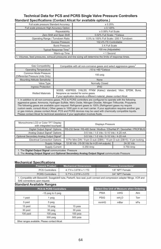
64
Technical Data for PCS and PCRS Single Valve Pressure ControllersStandard Specifications (Contact Alicat for available options.)
Full scale pressure Standard Accuracy ± 0.25%Full scale pressure High Accuracy Option ± 0.125%
Repeatability ± 0.08% Full ScaleZero Shift and Span Shift 0.02% Full Scale / ºCelsius
Operating Range / Turndown Ratio 0.5% to 100% Full Scale / 200:1 TurndownExcess Pressure 102.4% FS Controllable
Burst Pressure 3 X Full ScaleTypical Response Time1 100 ms (Adjustable)
Warm-up Time < 1 Second1. Volumes, feed pressures, exhaust pressures and line sizing will determine the limits of response times.
Gas Compatibility Compatible with all non-corrosive gases and select aggressive gases1
Operating Temperature -10 to +60 ºCelsiusCommon Mode Pressure
(Differential Pressure Units Only) 150 psig
Mounting Attitude Sensitivity NoneValve Type Normally Closed
Ingress Protection IP40
Wetted Materials303SS, 430FRSS, 316LSS, FFKM (Kalrez) standard; Viton, EPDM, Buna, Neoprene as needed for some gases.If your application demands a different material, please contact Alicat.
1. In addition to all non-corrosive gases, PCS & PCRS controllers are configured to operate with the following aggressive gases: Ammonia, Hydrogen Sulfide, Nitric Oxide, Nitrogen Dioxide, Nitrogen Triflouride, Propylene. The following gases are available upon request: Refrigerant gases to 100% (Refrigerant gases my require custom seals, consult Alicat.) Other gases to 1000 ppm in an inert carrier. If your application requires another gas or gas mixture, please contact Alicat. PCS and PCRS devices may be used with chemically compatible liquids. Please contact Alicat for technical assistance if your application involves fluids.
Monochrome LCD or Color TFT Display with integrated touchpad Displays Pressure
Digital Output Signal1 Options RS-232 Serial / RS-485 Serial / Modbus / EtherNet IP / DeviceNet / PROFIBUSAnalog Output Signal2 Options 0-5 Vdc / 1-5 Vdc / 0-10 Vdc / 4-20 mA
Optional Secondary Analog Output Signal2 0-5 Vdc / 1-5 Vdc / 0-10 Vdc / 4-20 mA Electrical Connection Options 8 Pin Mini-DIN / 9-pin D-sub (DB9) / 15-pin D-sub (DB15) / 6 pin locking
Supply Voltage 12-30 Vdc (15-30 Vdc for 4-20 mA outputs) 24-30 VdcSupply Current 0.250 Amp 0.750 Amp
1. The Digital Output Signal communicates Pressure 2. The Analog Output Signal and Optional Secondary Analog Output Signal communicate Pressure
Mechanical SpecificationsPressure Product Mechanical Dimensions Process Connections1
PCS Controllers 4.1”H x 3.6”W x 1.1”D 1/8” NPT FemalePCRS Controllers 5.7”H x 2.9”W x 5.5”D 3/4” NPT Female
1. Compatible with Beswick®, Swagelok® tube, Parker®, face seal, push connect and compression adapter fittings. VCR and SAE connections upon request.
Select One Unit of Measure when OrderingPSIA inHG Atm
PSIG inH2O Torr
mmHG mBar kPa
Standard Available RangesPCS & PCRS Controllers
-15 psig to 0 psig
1 psid 1 psig
5 psid 5 psig15 psid 15 psig 15 psia30 psid 30 psig 30 psia
100 psid 100 psig 100 psia500 psig 500 psia
0ther ranges available. Please contact Alicat.

65
5.617in
.375in
.200in47.63mm
142.67mm
9.53mm
5.08mm1.875in
2.700in68.58mm
28.58mm1.125in
1.120in28.45mm
Both Sides3/4 NPT
28.45mm1.120in
1.125in28.58mm
139.56mm5.495in
2.900in73.66mm
DATE
PCRS-100PSIG-D-MSPEC 1
12/12/2015
REV.
PCRS-Series:Most standard ranges
PCS-Series:All standard ranges to 500 psig
3.588in91.12mm
4.067in103.30mm
.525in13.34mm
.350in8.89mm
56.52mm2.225in
.150in3.81mm
3.18mm.125in
.925in23.50mm
2X 8-32 UNC .350in[8.89mm]
12/12/2015
PCS-100PSIG-D-MSPECREV.
DATE
1
8.89mm.350in
.525in13.34mm
Both Sides1/8 NPT
1.050in26.67mm

66
Technical Data for PCDS & PCDRS Dual Valve Pressure Controllers
Mechanical Specifications
Standard Specifications (Contact Alicat for available options.)Full scale pressure Standard Accuracy ± 0.25%
Full scale pressure High Accuracy Option ± 0.125%Repeatability ± 0.08% Full Scale
Zero Shift and Span Shift 0.02% Full Scale / ºCelsiusOperating Range / Turndown Ratio 0.5% to 100% Full Scale / 200:1 Turndown
Excess Pressure 102.4% FS ControllableBurst Pressure 3 X Full Scale
Typical Response Time1 100 ms (Adjustable)Warm-up Time < 1 Second
1. Volumes, feed pressures, exhaust pressures and line sizing will determine the limits of response times.
Gas Compatibility Compatible with all non-corrosive gases1
Operating Temperature -10 to +60 ºCelsiusCommon Mode Pressure
(Differential Pressure Units Only) 150 psig
Mounting Attitude Sensitivity None Mount with valve cylinder vertical & uprightValve Type Normally Closed
Ingress Protection IP40
Wetted Materials316LSS, 303SS, 430FRSS, FFKM (Kalrez) standard; Viton, EPDM, Buna, Neoprene as needed for some gases. If your application demands a different material, please contact Alicat.
1. In addition to all non-corrosive gases, PCDS & PCDRS controllers are configured to operate with the following aggressive gases: Ammonia, Hydrogen Sulfide, Nitric Oxide, Nitrogen Dioxide, Nitrogen Triflouride, Propylene. The following gases are available upon request: Refrigerant gases to 100% (Refrigerant gases my require custom seals, consult Alicat.) Other gases to 1000 ppm in an inert carrier. If your application requires another gas or gas mixture, please contact Alicat. PCS and PCRS devices may be used with chemically compatible liquids. Please contact Alicat for technical assistance if your application involves fluids.
Monochrome LCD or Color TFT Display with integrated touchpad Displays Pressure
Digital Output Signal1 Options RS-232 Serial / RS-485 Serial / Modbus / EtherNet IP / DeviceNet / PROFIBUSAnalog Output Signal2 Options 0-5 Vdc / 1-5 Vdc / 0-10 Vdc / 4-20 mA
Optional Secondary Analog Output Signal2 0-5 Vdc / 1-5 Vdc / 0-10 Vdc / 4-20 mA Electrical Connection Options 8 Pin Mini-DIN / 9-pin D-sub (DB9) / 15-pin D-sub (DB15) / 6 pin locking
Supply Voltage 12-30 Vdc (15-30 Vdc for 4-20 mA outputs) 24-30 VdcSupply Current 0.250 Amp 0.750 Amp
1. The Digital Output Signal communicates Pressure 2. The Analog Output Signal and Optional Secondary Analog Output Signal communicate Pressure
Dual Valve Pressure Controllers Mechanical Dimensions Process Connections1
PCDS All Standard Ranges 4.1”H x 4.8”W x 1.1”D 1/8” NPT Female
PCRD All Standard Ranges 5.5”H x 10.6”W x 2.3”D 3/4” NPT Female
1. Compatible with Swagelok® tube, Parker®, face seal, push connect and compression adapter fittings. VCR and SAE connections upon request.
Select One Unit of Measure when OrderingPSIA inHG Atm
PSIG inH2O Torr
mmHG mBar kPa
Standard Available RangesPCDS and PCRDS Controllers
-15 psig to 0 psig1 psid 1 psig5 psid 5 psig
15 psid 15 psig 15 psia30 psid 30 psig 30 psia
100 psid 100 psig 100 psia500 psig 500 psia
Other ranges available. Please contact Alicat.

67
PCDS-Series:Most standard ranges
PCDS-Series:Differential PressureMost standard ranges
4.800in121.92mm
26.67mm1.050in
DATE
PCDS-5PSIG-D-MSPECREV.1
12/12/2015
50.48mm1.988in 1/8 NPT
103.30mm4.067in
13.335mm.525in
8.89mm.350in
13.335mm.525in
.350in8.890mm
1/8 NPTBoth Sides
87.31mm3.438in
1.363in34.61mm
23.50mm.925in
.125in3.18mm
2X 8-32 UNC .350in 8.89mm
1/6/2016DATE
PCDS-1PSID-D-MSPEC 1REV.
116mm
2.721in69.10mm
52.82mm2.080in
4.567in
8.89mm.350in
2X 1/8 NPT
8.89mm.350in
13.34mm.525in
8.89mm.350in
52.82mm2.080in1/8 NPT
8.89mm.350in
13.34mm.525in 1/8 NPT
Both Sides
.125in3.18mm3.438in
87.31mm
.925in23.50mm
34.61mm1.363in
2X 8-32 UNC .300in 7.62mm
26.67mm1.050in
121.92mm4.800in

68
PCDRS-Series:Most standard ranges
68.58mm2.700in
8.33mm8X 8-32 UNC .328in
.200in5.08mm
9.53mm.375in
7.850in199.39mm 10.350in
262.89mm
47.63mm1.875in
57.15mm2.250in
3/4 NPT133.99mm5.275in
5.495in139.56mm
5.662in143.81mm
1.120in28.45mm
267.97mm10.550in
28.45mm1.120in
28.58mm1.125in
1/6/2016DATE
PCRDS-100PSIG-D-MSPEC 1REV.
28.45mm1.120in
3/4 NPTBoth Sides28.58mm
1.125in

69
Specification Meter or Gauge
Small ValveController
Large ValveController Description
Input /Output Signal Digital PROFIBUS DP
Electrical Connections DB9Supply Voltage: 7 to 30 Vdc 12 to 30 Vdc 24 to 30 Vdc
Supply Current 80mA @ 12Vdc65mA @ 24Vdc
295mA @ 12Vdc280mA @ 24Vdc 780mA @ 24Vdc
Technical Data for PROFIBUS Meters, Gauges and Controllers
NOTICE: The following specifications are applicable to Alicat PROFIBUS enabled meters, gauges and controllers only. All other operating specifications are shown in the Technical Data page for standard Alicat instruments.All standard device features and functions are available and operate in accordance with the standard Alicat Scientific device operating manual provided with the device.
Power and Signal Connections:Connect to the device using two DB9 connectors.The female top connection is PROFIBUS. The male connection on the side is power and RS-232 or RS-485.Pin out diagrams for all PROFIBUS enabled Alicat devices are shown:
PROFIBUS MC1SLPM shown to provide PROFIBUS connector dimensions only. Flow body and valve dimensions will vary with range. Please see Alicat’s device specifications for complete dimensions.
PROFIBUS units do not have a display screen.
2 x 8-32 UNC v .350
.525
.35
4.264.08
3.76
3.59
1/8 NPTBoth Sides
1.05
.525
.35
2.225.150 .125
.925
MC-1SLPM-PROFIBUS
5 19 6
TOP16
59
SIDE
1. Not Connected2. RS-232 RX3. RS-232 TX4. Not Connected5. Ground6. No Connected7. 7 to 30VDC8. Ground9. Not Connected
1. Not Connected2. PoP Ground (Power over Profibus option)3. Rx/Tx Data-P4. Request To Send5. Data Ground6. Voltage Plus7. PoP 7 to 30VDC8. Rx/Tx Data-N9. Not ConnectedTOP: Pins 3, 5 & 8 are required. All other pin connections are optional.

70
Eight Pin Mini-DIN Connector Pin-OutsIf your Alicat Instrument was ordered with the standard Eight Pin Mini-DIN
connection, please be sure to reference the following pin-out diagram.
Standard 8 Pin Mini-DIN Pin-Out
1 2
3 4 5
6 7 8
Pin Function Mini-DIN cable color
1 Inactive (or optional 4-20mA Primary Output Signal) Black
2 Static 5.12 Vdc [or optional Secondary Analog Output (4-20mA, 5Vdc, 10Vdc) or Basic Alarm] Brown
3 Serial RS-232RX / RS-485(–) Input Signal (receive) Red
4 Meters/Gauges = Remote Tare (Ground to Tare)Controllers = Analog Set-Point Input Orange
5 Serial RS-232TX / RS-485(+) Output Signal (send) Yellow6 0-5 Vdc (or optional 0-10 Vdc) Output Signal Green7 Power In (as described above) Blue
8 Ground (common for power, digital communications, analog signals and alarms) Purple
Note: The above pin-out is applicable to all pressure gauges and controllers with the Mini-DIN connector. The availability of different output signals depends on the options ordered. Optional configurations are noted on the unit’s calibration sheet.

71
520-290-6060 Ph. 520-290-0109 Fax
7641 N Business Park Dr. Tucson, AZ 85743
Rev. No. Description Date
1
6
5
4
3
2
520-290-6060 Ph. 520-290-0109 Fax
7641 N Business Park Dr. Tucson, AZ 85743
Rev. No. Description Date
1
6
5
4
3
2
The above pin-out is applicable to all pressure gauges and controllers ordered with the industrial connector. The availability of different output signals depends on the flow meter options ordered.
Locking Industrial Connector Pin-OutsIf your Alicat Instrument was ordered with a Six Pin Locking Industrial connection, please be sure to reference the following pin-out diagram.
Pin Function1 Power In ( + )2 RS-232TX / RS-485(+)3 RS-232RX / RS-485(-)4 Meters/Gauges = Remote Tare (Ground to Tare)
Controllers = Analog Set-Point Input5 Ground (common for power, communications and signals)6 Signal Out (Voltage or Current as ordered)
Male Connector: Cable Female Connector: Device
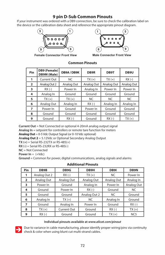
72
9 pin D-Sub Common PinoutsIf your instrument was ordered with a DB9 connection, be sure to check the calibration label on the device or the calibration data sheet and reference the appropriate pinout diagram.
Common Pinouts
Pin DB9 (Female)DB9M (Male) DB9A / DB9K DB9R DB9T DB9U
1 Current Out NC TX (+) TX (+) RX (-)2 Analog Out 2 Analog Out Analog Out Analog Out Analog Out3 RX (-) Power In Analog In Power In Power In4 Analog In Ground Ground Ground Ground5 TX (+) TX (+) NC NC NC6 Analog Out Analog In RX (-) Analog In Analog In7 Power In Ground Power In Ground Ground8 Ground Ground Ground Ground Ground9 Ground RX (-) Ground RX (-) TX (+)
Current Out = Not Connected or optional 4-20mA analog output signalAnalog In = setpoint for controllers or remote tare function for metersAnalog Out = 0-5 Vdc Output Signal (or 0-10 Vdc optional) Analog Out 2 = 5.12Vdc or Optional Secondary Analog OutputTX (+) = Serial RS-232TX or RS-485(+)RX (-) = Serial RS-232RX or RS-485(-)NC = Not ConnectedPower In = (+Vdc) Ground = Common for power, digital communications, analog signals and alarms
Additional PinoutsPin DB9B DB9G DB9H DB9I DB9N
1 Analog Out 2 RX (-) TX (+) NC Power In2 Analog Out Analog Out Analog Out Analog Out Analog In3 Power In Ground Analog In Power In Analog Out4 Ground Power In RX (-) Ground NC5 Ground Ground Analog Out 2 NC Ground6 Analog In TX (+) NC Analog In Ground7 Ground Analog In Power In Ground RX (-)8 TX (+) Current Out Ground RX (-) TX (+)9 RX (-) Ground Ground TX (+) NC5
Individual pinouts available at www.alicat.com/pinout
Due to variance in cable manufacturing, please identify proper wiring/pins via continuity check & color when using blunt cut multi-strand cables.
Male Connector Front View
7641 N Business Park Dr. Tucson, AZ 85743
520-290-6060 Ph. 520-290-0109 Fax
96
1 5
Female Connector Front View
7641 N Business Park Dr. Tucson, AZ 85743
520-290-6060 Ph. 520-290-0109 Fax
9 6
15

73
15 pin D-Sub Common Pinouts If your instrument was ordered with a DB15 connection, be sure to check the calibration label on the device or the calibration data sheet and reference the appropriate pinout diagram.
Pin DB15 DB15A DB15B DB15H DB15K DB15O DB15S
1 Ground Ground Ground NC NC Ground Ground
2 Analog Out Analog Out Analog Out RX (-) Analog Out NC Analog Out
3 Ground Analog In NC NC NC NC NC
4 NC Ground NC NC NC Analog Out NC
5 Power In Ground Power In Ground Ground Power In Ground
6 NC Ground NC Analog Out NC NC NC
7 NC Power In NC Ground Power In Analog In NC
8 Analog In TX (+) Analog In NC Analog In NC5 Analog In
9 Ground Ground Ground NC Analog Out 2 Ground Ground
10 Ground NC Ground Analog Out 2 NC Ground Ground
11 Analog Out 2 NC Analog Out 2 Power In Ground Analog Out 2 Analog Out 2
12 NC Analog Out 2 NC Ground Ground NC RX (-)
13 RX (-) NC NC NC RX (-) NC Power In
14 Ground NC RX (-) Analog In TX (+) RX (-) TX (+)
15 TX (+) RX (-) TX (+) TX (+) Ground TX (+) Ground
Analog In = setpoint for controllers or remote tare function for metersAnalog Out = 0-5 Vdc Output Signal (or 0-10 Vdc optional) Analog Out 2 = 5.12Vdc or Optional Secondary Analog OutputTX (+) = Serial RS-232TX or RS-485(+)RX (-) = Serial RS-232RX or RS-485(-)NC = Not ConnectedPower In = (+Vdc) Ground = Common for power, digital communications, analog signals and alarms
Individual pinouts available at www.alicat.com/pinout
Due to variance in cable manufacturing, please identify proper wiring/pins via continuity check & color when using blunt cut multi-strand cables.
Female Connector Front View
8
15 13 11 9
25
Male Connector Front View
8
1513119
2 5
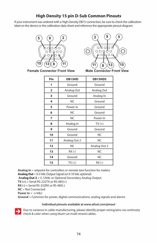
74
High Density 15 pin D-Sub Common PinoutsIf your instrument was ordered with a High Density DB15 connection, be sure to check the calibration label on the device or the calibration data sheet and reference the appropriate pinout diagram.
Pin DB15HD DB15HDS
1 Ground Ground
2 Analog Out Analog Out
3 Ground Analog In
4 NC Ground
5 Power In Ground
6 NC Ground
7 NC Power In
8 Analog In TX (+)
9 Ground Ground
10 Ground NC
11 Analog Out 2 NC
12 NC Analog Out 2
13 RX (-) NC
14 Ground NC
15 TX (+) RX (-)
Analog In = setpoint for controllers or remote tare function for metersAnalog Out = 0-5 Vdc Output Signal (or 0-10 Vdc optional) Analog Out 2 = 5.12Vdc or Optional Secondary Analog OutputTX (+) = Serial RS-232TX or RS-485(+)RX (-) = Serial RS-232RX or RS-485(-)NC = Not ConnectedPower In = (+Vdc) Ground = Common for power, digital communications, analog signals and alarms
Individual pinouts available at www.alicat.com/pinout
Due to variance in cable manufacturing, please identify proper wiring/pins via continuity check & color when using blunt cut multi-strand cables.
\\Alicat-server2\Public\Drawings\SolidWorks Drawings\Work\Numbered Parts\410495(15pin Dsub Pannel Female IP67(AE10114-ND))\
D
C
B
AA
B
C
D
12345678
8 7 6 5 4 3 2 1
SIZE PART NO./DESCRIPTION
AREV.
MATERIAL
FINISH316L Stainless
--
DIMENSIONS ARE IN INCHESTOLERANCES:ANGULAR: 0 30'TWO PLACE DECIMAL .015THREE PLACE DECIMAL .005
THE INFORMATION CONTAINED IN THISDRAWING IS THE SOLE PROPERTY OFALICAT SCIENTIFIC, INC. ANY REPRODUCTION IN PART OR AS A WHOLEWITHOUT THE WRITTEN PERMISSION OFALICAT SCIENTIFIC, INC. IS PROHIBITED.
PROPRIETARY AND CONFIDENTIAL
15pin HD Dsub Pannel Female (manual)
DATE12/18/08
0
7641 N Business Park Dr. Tucson, AZ 85743520-290-6060 Ph. 520-290-0109 Fax
Checked by
--Blank #
Notes:1. Break all sharp edges .005/.015 x 45 Deg. Radius optional.2. Transport as to prevent damage3. No nicks or dings allowed on machined surfaces.4. Remove all burrs5. Do not Scale Drawing 6. Use listed material when blank is unavailable
815 13 11
9 25
151311
2 5
\\Alicat-server2\Public\Drawings\SolidWorks Drawings\Work\Numbered Parts\410495(15pin Dsub Pannel Female IP67(AE10114-ND))\
D
C
B
AA
B
C
D
12345678
8 7 6 5 4 3 2 1
SIZE PART NO./DESCRIPTION
AREV.
MATERIAL
FINISH316L Stainless
--
DIMENSIONS ARE IN INCHESTOLERANCES:ANGULAR: 0 30'TWO PLACE DECIMAL .015THREE PLACE DECIMAL .005
THE INFORMATION CONTAINED IN THISDRAWING IS THE SOLE PROPERTY OFALICAT SCIENTIFIC, INC. ANY REPRODUCTION IN PART OR AS A WHOLEWITHOUT THE WRITTEN PERMISSION OFALICAT SCIENTIFIC, INC. IS PROHIBITED.
PROPRIETARY AND CONFIDENTIAL
15pin HD Dsub Pannel Female (manual)
DATE12/18/08
0
7641 N Business Park Dr. Tucson, AZ 85743520-290-6060 Ph. 520-290-0109 Fax
Checked by
--Blank #
Notes:1. Break all sharp edges .005/.015 x 45 Deg. Radius optional.2. Transport as to prevent damage3. No nicks or dings allowed on machined surfaces.4. Remove all burrs5. Do not Scale Drawing 6. Use listed material when blank is unavailable
\\Alicat-server2\Public\Drawings\SolidWorks Drawings\Work\Numbered Parts\410495(15pin Dsub Pannel Female IP67(AE10114-ND))\
D
C
B
A A
B
C
D
1 2 3 4 5 6 7 8
87654321
SIZEPART NO./DESCRIPTION
AREV.
MATERIAL
FINISH316L Stainless
--
DIMENSIONS ARE IN INCHESTOLERANCES:ANGULAR: 0 30'TWO PLACE DECIMAL .015THREE PLACE DECIMAL .005
THE INFORMATION CONTAINED IN THISDRAWING IS THE SOLE PROPERTY OFALICAT SCIENTIFIC, INC. ANY REPRODUCTION IN PART OR AS A WHOLEWITHOUT THE WRITTEN PERMISSION OFALICAT SCIENTIFIC, INC. IS PROHIBITED.
PROPRIETARY AND CONFIDENTIAL
15pin HD Dsub Pannel Female (manual)
DATE12/18/08
0
7641 N Business Park Dr. Tucson, AZ 85743520-290-6060 Ph. 520-290-0109 Fax
Checked by
--Blank #
Notes:1. Break all sharp edges .005/.015 x 45 Deg. Radius optional.2. Transport as to prevent damage3. No nicks or dings allowed on machined surfaces.4. Remove all burrs5. Do not Scale Drawing 6. Use listed material when blank is unavailable
8
9
Male Connector Front ViewFemale Connector Front View

75
NOTES FOR USING PC-EXTSEN DEVICESPC-EXTSEN units connect a Pressure Controller (with no internal pressure sensor) to an end-user supplied external pressure sensor. Designed mainly for the vacuum coating industry, the PC-EXTSEN marries the sensing ability of an existing capacitance manometer or ion gauge with a Alicat’s 16 Series electronics package and internal PID algorithm. This enables fast and precise control of extreme vacuum conditions in the coating chamber.
The PC-EXTSEN receives a linear analog signal from the external sensor. This analog signal corresponds to a full scale range that is specified by the user at the time of order (and corresponds to the scale of the external sensor). The PC-EXTSEN interprets this analog signal as its sensed pressure.
The PC-EXTSEN then utilizes its proportional control valve to control the flow of gas into the chamber, allowing for closed loop vacuum control based on the interpreted signal. Set-point control and PID tuning all happen through the instrument’s interface, via the buttons on the display, or a user selected analog interface (0-5V, 0-10V, or 4-20mA), or through a multidrop RS-232 interface.
There are two base models of PC-EXTSEN controllers, the PC-EXTSEN-D, and the PC-EXTSEN-D-ISC.
The PC-EXTSEN-D has an 8 pin Mini-DIN female electrical connector as its electrical connection to power, ground, signal input from the external sensor, RS-232 transmit and receive, as well as analog transmit and receive. The PC-EXTSEN-D also has a barrel plug electrical connection if you choose to power the device through a wall mounted AC adaptor, rather then wiring power to the 8 pin minidin connection.
The PC-EXTSEN-D-ISC is identical to the PC-EXTSEN-D except it has an additional locking 6 pin industrial electrical connector which is intended for use as a dedicated connection to your external sensor, leaving the 8 pin Mini-DIN connection available to be used as a dedicated RS-232 or analog interface connection.
Please refer to the appropriate sections of this operating manual for complete information regarding use and tuning of your PC-EXTSEN controller.
When using a PC-EXTSEN-D-ISC device, it is recommended that power and communications to the PC-EXTSEN-D-ISC device be wired through the 8 pin Mini-DIN connector and that the industrial connector is maintained as a dedicated connection to the external sensor.
WHEN USING THE INDUSTRIAL CONNECTOR AS A DEDICATED CONNECTION TO THE SENSOR, DO NOT WIRE ANY SIGNAL INPUT INTO PIN 2 ON THE Mini-DIN CONNECTOR.

76
PC-EXTSEN-D Pin-OutsThe following pin-out diagram is applicable to all standard PC-EXTSEN-D devices. If your device was ordered with custom pin-out requirements, please contact Alicat for assistance.
PC-EXTSEN-D Standard 8 Pin Mini-DIN Pin-Out
1 Inactive or 4-20mA Primary Output Signal Black2 External Sensor Signal Input* Brown3 RS-232 Input Signal Red4 Analog Input Signal Orange5 RS-232 Output Signal Yellow6 0-5 Vdc (or 0-10 Vdc) Output Signal Green7 Power In Blue8 Ground (common for power, communications and signals) Purple
*If you are using the PC-EXTSEN-D-ISC’s 6 pin locking connection to receive the external sensor input signal do not wire any signal into pin 2 of the Mini-DIN.
Pin 7 which is normally utilized to provide power into the Alicat device can be used to provide power to your external sensor. Please make sure that the power you are providing to the device is compatible with the power your sensor can accept before choosing to wire power in this manner.
CAUTION! Do not connect power to pins 1 through 6 as permanent damage can occur!
POWER AND SIGNAL CONNECTIONSPower can be supplied to your controller through either the power jack or the 8 pin Mini-DIN connector. An AC to DC adapter which converts line AC power to DC voltage and current as specified below is required to use the power jack. A 2.1mm, positive center, 12-30 Vdc AC/DC adapter rated for at least 250 mA is required to use the adapter jack in a PC-Series controller. A 2.1mm, positive center, 24-30 Vdc AC/DC adapter rated for at least 500 mA is required to use the adapter jack in a PCR-Series controller.NOTE: 4-20mA analog output requires at least 15 Vdc.

77
PC-EXTSEN-D-ISC Pin-OutsThe PC-EXTSEN-D-ISC is equipped with an additional Four Pin Locking connection, for use as a dedicated connection to your external sensor.
This leaves the 8 pin Mini-DIN connection available to be used as a dedicated RS-232 or analog interface connection.
Please be sure to reference the following pin-out diagram. The following pin-out diagram is applicable to all standard PC-EXTSEN-D-ISC devices. If your device was ordered with custom pin-out requirements, please contact Alicat for assistance.
Pin Function Cable Color1 Sensor Power In ( +12 Vdc to +24 Vdc ) Red2 In-Active Blue3 External Sensor Signal Input Green4 Ground (common for power,
communications and signals)Black
PC-EXTSEN-D-ISC Standard 4 Pin Locking Connection Pin-Out
Pin 1 which is normally utilized to provide power into the Alicat device can be used to provide power to your external sensor. Please make sure that the power you are providing to the device is compatible with the power your sensor can accept before choosing to wire power in this manner.
When using a PC-EXTSEN-D-ISC device, it is recommended that power and communications to the PC-EXTSEN-D-ISC device be wired through the 8 pin connector and that the industrial connector is maintained as a dedicated connection to the external sensor.
WHEN USING THE INDUSTRIAL CONNECTOR AS A DEDICATED CONNECTION TO THE SENSOR, DO NOT WIRE ANY SIGNAL INPUT INTO PIN 2 ON THE Mini-DIN CONNECTOR.
The 4 pin locking connection on the –ISC unit has only three active pins, power, ground and signal input from the external sensor.
PC-EXTSEN-D-ISC
4 Pin Locking Connection
8 Pin Mini-DIN Connection End-user Supplied External Sensor
520-290-6060 Ph. 520-290-0109 Fax
7641 N Business Park Dr. Tucson, AZ 85743
Rev. No. Description Date
1 4
32
Female Connector: Device

78
Additional Information for Alicat CSA and ATEX Approved Devices
EEx nA IIC T4 Class I, Div. 2 Group A, B, C and D T4
24 Vdc, 0.800A maxClass I, Zone 2 AEx nA IIC T4
WARNINGS: EXPLOSION HAZARD – DO NOT DISCONNECT WHILE CIRCUIT IS LIVE UNLESS AREA IS KNOWN TO BE NON-HAZARDOUS.EXPLOSION HAZARD – SUBSTITUTION OF COMPONENTS MAY IMPAIR SUITABILITY FOR CLASS I, DIVISION 2.
II 3 G
Alicat CSA / ATEX approved devices are equipped with either a locking six pin industrial connector (IC), locking D-sub 15 pin connector (DB15) or locking D-sub 9 pin connector (DB9). Please see pages 71 - 74 for the correct power and signal connections for each type of connector.
See the following page for special conditions regarding the use of these units!

79
USE of Alicat instruments (L, LC, LCR, M, MW, MS, MC, MCW, MCS, MCR, MCRW, MCRS, MCD, P, PS, PC, PCD, PCS, PCR and PCRS product families) in Class 1 Division 2 applications.
CSA certifies the use of this product for general use as well as use in hazardous locations as defined by Class 1 Division 2 Group A, B, C and D T4. CSA certification is indicated by the product label as shown below and not by the statements in this, or any accompanying documentation.
Special Conditions:To comply with CSA certification the following information is included in the product literature:
• When equipment is properly labeled, it is suitable in Class I, Division 2, Group A, B, C and D, T4
o Tamb. -40°C to +50°C • Electrical Rating 24Vdc, 0.800A max• Instruments shall be powered by a CSA certified, UL listed, Class II external power
supply suitable for the application• Instruments shall be housed in an enclosure with a minimum IP54 rating or location
providing equivalent protection• Instrument’s final approval shall be provided by the local authority having jurisdiction
EEx nA IIC T4 Class I, Div. 2 Group A, B, C and D T4
24 Vdc, 0.800A maxClass I, Zone 2 AEx nA IIC T4
X – See manual for special conditionsWARNINGS:
EXPLOSION HAZARD – DO NOT DISCONNECT WHILE CIRCUIT IS LIVE UNLESS AREA IS KNOWN TO BE NON-HAZARDOUS.EXPLOSION HAZARD – SUBSTITUTION OF COMPONENTS MAY IMPAIR SUITABILITY FOR CLASS I, DIVISION 2.
www.AlicatScientific.com
Alicat Scientific, Inc.Tucson, AZ USATel: 520-290-6060
II 3 G
USE of Alicat instruments (L, LC, LCR, M, MW, MS, MC, MCD, MCW, MCS, MCR, MCRW, MCRS, P, PS, PC, PCD, PCS, PCR and PCRS product families) in applications requiring ATEX Class 1 Zone 2 Certification.
Properly labeled Alicat instruments comply to the following ATEX standard:
II 3 G EEx nA IIC T4 (-40°C ≤ Ta ≤ +50°C)The examination certificate was issued by the CSA in accordance with accepted practices and procedures. This confirms compliance with the
European ATEX Directive or Group II Category 3G equipment.ATEX certification is indicated by the product label as shown above and not by the statements in this, or any accompanying documentation.Special Conditions:
• Properly labeled equipment is only certified for use in ambient temperatures in the range of -40°C to +50°C only
• Electrical Rating 24Vdc, 0.800A max• Instruments shall be powered by a CSA certified, UL listed, Class II external power
supply suitable for the application• Instruments shall be housed in an enclosure with a minimum IP54 rating or location
providing equivalent protection• Instrument’s final approval shall be provided by the local authority having jurisdiction

80

Serial Number: ______________________Model Number: _________________________Notice: Alicat Scientific, Inc. reserves the right to make any changes and improvements to the products described in this manual at any time and without notice. This manual is copyrighted. This document may not, in whole or in part, be copied, reproduced, translated, or converted to any electronic medium or machine readable form, for commercial purposes, without prior written consent from the copyright holder.Note: Although we provide assistance on Alicat Scientific products both personally and through our literature, it is the complete responsibility of the user to determine the suitability of any product to their application.
Limited Lifetime WarrantyAlicat Scientific, Inc. warrants to the original purchaser (hereinafter referred to as “Buyer”) that instruments manufactured by Alicat Scientific (hereinafter referred to as “Product”) shall be free from defects in materials and workmanship for the life of the Products.Under this warranty, the Products will be repaired or replaced at manufacturer’s option, without charge for parts or labor when the Product is carried or shipped prepaid to the factory together with proof of purchase.The foregoing shall constitute the exclusive and sole remedy in lieu of other remedies of the Buyer for any breach by Alicat Scientific of this warranty to the maximum extent permitted by law.This warranty does not apply to any Product which has not been installed or used in accordance with the Product operation and installation specifications provided to Buyer verbally or in writing by Alicat Scientific for the proper and normal use of the Product.Buyer agrees hereunder that Alicat reserves the right to void any warranty, written or implied, if upon Alicat’s examination of Product shall disclose to Alicat’s satisfaction that the Product failure was due solely, or in part, to accident, misuse, neglect, abuse, alteration, improper installation, unauthorized repair or improper testing by Buyer or agent of Buyer.Alicat Scientific shall not be liable under any circumstances for indirect, special, consequential, or incidental damages in connection with, or arising out of, the sale, performance, or use of the Products covered by this warranty.Alicat Scientific does not recommend, warrant or assume responsibility for the use of the Products in life support applications or systems.Alicat’s warranties as herein above set forth shall not be enlarged, diminished or affected by, and no obligation or liability shall arise or grow out of Alicat’s rendering of technical advice in connection with Buyer’s order of the Products furnished hereunder.If Product becomes obsolete, Alicat Scientific, at its own discretion, reserves the right to repair the Product with available replacement parts or upgrade the Product to a current, commercially available version of the original Product. Should upgrading the Product be deemed necessary by Alicat, Buyer hereby agrees to pay an upgrade fee equal to seventy percent of the retail value of the replacement Product. Alicat Scientific hereunder makes no claim that replacement Products will look, function or operate in the same or similar manner as the original product.When a Product is returned to Alicat Scientific for recalibration this service is considered normal preventative maintenance. Recalibration of Product shall not be treated as a warranty service unless recalibration of Product is required as the result of repairs to Product pursuant to this Warranty. Failure of Buyer to send Product to Alicat Scientific for recalibration on a yearly basis after a period of 36 months from date of manufacture will remove any and all obligations regarding repair or replacement of Product as outlined by this Warranty to Buyer from Alicat Scientific.This Warranty is in lieu of all other relevant warranties, expressed or implied, including the implied warranty of merchantability and the implied warranty of fitness for a particular purpose, and any warranty against infringement of any patent.Continued use or possession of Products after expiration of the applicable warranty period stated above shall be conclusive evidence that the warranty is fulfilled to the full satisfaction of Buyer. Alicat makes no warranty as to experimental, non-standard or developmental Products.Accessories purchased from Alicat are not covered by this warranty.
Conformity / Supplemental Information:The product complies with the requirements of the Low Voltage Directive 2014/35/EU, the EMC Directive 2014/30/EU and the RoHS Directive 2011/65/EU and carries the CE Marking accordingly. Contact the manufacturer for more information.

SCFM
1.00=
28.3160SLPM
SLPM100.00
=3.5316
SCFM
SCFH
1.00=
0.4719SLPM
SLPM100.00
=211.9093
SCFH
SCIM
100.00=
1.6390SLPM
SLPM1.00
=61.0128
SCIM
SCIH
1000.00=
0.2732SLPM
SLPM1.00
=3660.7688
SCIH
Flow C
onversions:
alicat.com
The Fastest Flow C
ontroller Com
pany in the World!
7641 N B
usiness Park Drive
Tucson AZ 85743 U
SAPhone: 888-290-6060
Fax: 520-290-0109
#G
asA
bsoluteViscosity*
25°C
Density **25°C
14.696 psia
Com
pressibility 25°C
14.696 psia0
Air
Air
184.89891.1840
0.99971
Argon
Ar
226.23991.6339
0.99942
Methane
CH
4110.7595
0.65690.9982
3C
arbon Monoxide
CO
176.49331.1453
0.99964
Carbon D
ioxide C
O2
149.31841.8080
0.99505
Ethane C
2H6
93.54121.2385
0.99246
Hydrogen
H2
89.15350.08235
1.00067
Helium
H
e198.4561
0.163531.0005
8N
itrogen N
2178.0474
1.14530.9998
9N
itrous Oxide
N2O
148.41241.8089
0.994510
Neon
Ne
311.12640.8244
1.000511
Oxygen
O2
205.50211.3088
0.999412
Propane C
3H8
81.46311.8320
0.983813
normal-B
utane n-C
4H10
74.05362.4493
0.969914
Acetylene
C2H
2104.4480
1.07200.9928
15Ethylene
C2H
4103.1839
1.15330.9943
16iso-B
utane i-C
4H10
74.78462.4403
0.973517
Krypton
Kr
251.32493.4323
0.997918
Xenon Xe
229.84835.3950
0.994719
Sulfur Hexafluoride
SF6153.5320
6.03830.9887
#G
asA
bsoluteViscosity*
25°C
Density **25°C
14.696 psia
Com
pressibility 25°C
14.696 psia20
75%A
r / 25% C
O2
C-25
206.97631.6766
0.998721
90% A
r / 10% C
O2
C-10
218.60261.6509
0.999122
92% A
r / 8% C
O2
C-8
220.13521.6475
0.999223
98% A
r / 2% C
O2
C-2
224.71481.6373
0.999324
75% C
O2 / 25%
Ar
C-75
168.22501.7634
0.996625
75% A
r / 25% H
eH
E-75231.6056
1.26600.9997
2675%
He / 25%
Ar
HE-25
234.68600.5308
1.0002
2790%
He / 7.5%
Ar /
2.5% C
O2
Helistar®
A1025
A1025
214.97600.3146
1.0003
2890%
Ar / 8%
CO
2 / 2%
O2
Stargon® C
SStar29
219.79341.6410
0.9992
2995%
Ar / 5%
CH
4P-5
223.91061.5850
0.9993*in m
icropoise (1 Poise = gram / (cm
) (sec)) **Gram
s/Liter R
eference: NIST R
EFPRO
P 9 Database
Gas V
iscosity, Density and C
ompressibility:


![Honeywell Pressure SwitchesHoneywell Pressure Switches High Pressure: HP Series, HE Series Factory set 150 psi to 4500 psi [10,34 bar to 310,26 bar] Low Pressure: LP Series, LE Series](https://img.pdfslide.us/doc/110x75/60ad806272620b5c0e1b1975/honeywell-pressure-switches-honeywell-pressure-switches-high-pressure-hp-series.jpg)